Embed Size (px)
Citation preview
REMOTE INSPECTION OF THE IFSF SPENT FUEL STORAGE RACK
EVERT D. ULDRICH LOCKKEED MARTIN IDAHO TECHNOLOGIES
P. 0. BOX 1625 IDAHO FALLS, IDAHO 83415-3760
INTRODUCTION
The Irradiated Fuel Storage Facility (IFSF) is a dry storage facility for spent nuclear fuels located at the Idaho Chemical Processing Plant at the Idaho National Engineering Laboratory, a U.S. Department ofEnergy (DOE) research facility located near Idaho Falls, Idaho. It was designed and constructed in the early 1970's specifically for the Fort Saint Vrain spent reactor fuels. Currently, it is being used for various spent fuels.
The design seismic criteria was an equivalent static horizontal acceleration of 0.33 g with a 1.30 ground amplification. That analysis method neglects the effects of natural frequency and amplifications due to resonance. It was not known if the facility would meet the current DOE seismic criteria, so a phased re-analysis of the facility was started, with the fuel storage rack being analyzed first.
In the process, it was discovered that the fabrication drawings of the fuel storage rack could not be found. The design drawings of the rack showed only a few weld symbols and was confusing on the number of diagonal braces and the number of concrete anchors. Therefore, this inspection was conducted to determine the as-built condition of the rack. More specifically, to measure the sizes of the unspecified welds, to count the number of diagonal braces, and to determine the number of concrete anchors.
Since the rack is about 50% occupied with spent reactor fuel which resulted in radiation readings up to 221 Radshour, a remote, closed circuit television inspection of the rack was required. This fuel storage rack contains 636 fuel storage locations, also called ports. Each port is about 19-in. in diameter by about 1 1 -ft tall. Only ports with no spent fuel were inspected. This remote inspection is described and evaluated herein.
INSPECTION EQUIPMENT
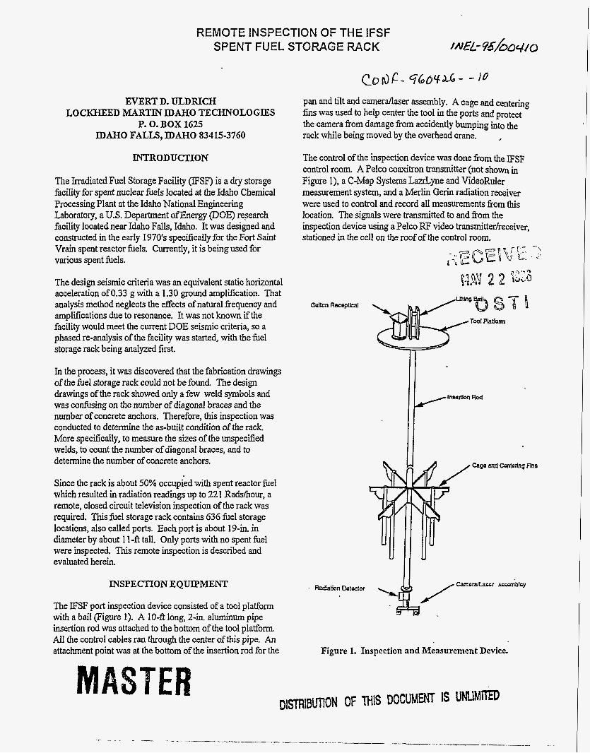
The IFSF port inspection device consisted of a tool platform with a bail (Figure 1). A IO-ft long, 2-in. aluminum pipe insertion rod was attached to the bottom of the tool platform. All the control cabibles ran through the center of this pipe. An attachment point was at the bottom of the insertion rod for the
pan and tilt and camerdaser assembly. A cage and centering fins was used to help center the tool in the ports and protect the camera from damage from accidently bumping into the rack while being moved by the overhead crane. ,
The control of the inspection device was done from the ESF control room. A Pelco coaxitron transmitter (not shown in Figure I), a C-Map Systems LazrLyne and VideoRuler measurement system, and a Merlin Gerin radiation receiver were used to control and record all measurements from this location. The signals were transmitted to and fkom the inspection device using a Pelco RF video transmitterlreceiver, stationed in the cell on the roof of the control room.
Gultan Recepllcal
Cage and Contodng Flns
/-o-r-b'sy
Figure 1. Inspection and Measurement Device.
DlSTRlBUffON OF THIS DOCUMENT 1s UNllMcFEo
--
The following items were located on the tool platform of the inspection device (Figure 1). A Pelco coaxitron multiplex receiver (not shown) was used to control the pan, tilt, and lights. An Elmo camera control unit was used to supply the camera with power and a video signal return. A 250w light (not shown) was located on the top plate to illuminate the port. A Gulton receptacle was used to supply I lOvAC to the coaxitron multiplex receiver and the DC power supply. The Gulton plug was connected via a retractable cable to the overhead crane. All of the electronics were protected by a plexi-glass shield (not shown).
Located on the bottom of the inspection device (Figure 1) was a Brooks Pandora pan and tilt (not shown) and a radiation detector. On the pan and tilt was mounted an Elmo camera, a Carley I2vDC light (not shown), and a Power Technology laser diode. The camera and laser were aligned to each other and calibrated to provide the measurements.
The LazrLyne provides precise, instant image scaling for measurements with the VideoRuler micrometer. The LazrLyne system uses a solid state laser to optically project a bright red vertical stripe into the video image. The operator freezes the video, clicks the stripe (which scales the image), and then uses the VideoRuler to measure distances anywhere in the image.
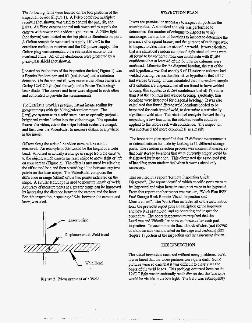
Offsets along the a..s of the video camera lens can be measured. An example of this would be the height of a weld bead, An offset is actually a change in range from the camera to the object, which causes the laser stripe to move right or left on your screen (Figure 2). The offset is measured by clicking the offset tool icon and then stretching a line between any two points on the laser stripe. The VideoRuler computes the difference in range (offset) of the two points indicated on the stripe, A similar technique is used to measure length of welds. Accuracy of measurements at a greater range can be improved by increasing the distance between the camera and the laser. For this inspection, a spacing of 6-in. between the camera and laser, was used.
Displacement at Weld Bead
\- Weld Bead
Figure 2. Measurement of a Weld.
INSPECTION PLAN
It was not practical or necessary to inspect all ports for the missing data. A statistical analysis was performed to determine: the number of columns to inspect to veriQ anchorage, the number of locations to inspect to determine the presence of diagonal braces, and the number of each type weld to inspect to determine the size of that weld. It was calculated that if a statistical random sample of eight steel columns were all found to be anchored, then one could state with 81,.6% confidence that at least 46 of the 56 interior columns were anchored. Likewise for the diagonal bracing, the test of the null hypothesis was that exactly 9 of 17 exterior columns had welded bracing, versus the alternative hypothesis that all 17 had welded bracing. It was calculated that S a random sample Of 3 columns are inspected and all are found to have welded bracing, this equates to 87.6% confidence that all 17, rather than 9 of the columns had welded bracing. (Actually, four locations were inspected for diagonal bracing.) It was also calculated that four different weld locations needed to be inspected for each type of weld, to determine a statistically signifcant weld size. This statistical analysis showed that by inspecting a few locations, the obtained results could be applied to the whole rack with confidence. The inspection was shortened and more economical as a result.
The inspection plan specified that 17 different measurements or determinations be made by looking in 11 different storage ports. The random selection process was somewhat biased, so that only storage locations that were currently empty would be designated for inspection. This eliminated the associated risk of handling spent nuclear fuel when it wasn't absolutely necessary.
This resulted in a report "Remote Inspection Guide Diagrams". The report identified which specific ports were to be inspected and what items in each port were to be inspected. From that report another report was written, "Work Plan IFSF Fuel Storage Rack Remote Visual Inspection and Measurement". The Work Plan included all of the information from the previous report plus a description of the hardware and how it is assembled, and an operating and inspection procedure. The operating procedure required that the LazrLyne and VideoRuler be re-calibrated after each port inspection. To accommodate this, a block of steel (not shown) of a known size was mounted on the cage and centering pins (Figure 1) portion of the inspection and measurement device.
THE, ICNSPECTION
The actual inspection occurred without manyproblems. First, it was found that the video pictures were quite dark. Some pictures were so dark that it was difficult to clearly see the edges of the weld beads. This problem occurred because the 12vDC light was intentionally made dim so that the LazrLyne would be visible in the low light. The bulb was subsequently
replaced with one with greater candle power. Secondly, it was discovered that if the inspection was narrated, the viewing of the video tapes would be much more meaningiil. Thirdly, it was found to be valuable to have a hand-written report in addition to the computer generated report of the measurements and observations.
Very few surprises were found during the inspection. An interior columns was found to have a 0.25-in. thick shim plate between it and the anchor. It was suspected that the shim plate was used to make-up for some irregularity in the concrete floor surface. The design drawings show the horizontal beams intersecting the vertical columns. In one case it was observed where a beam passed on the side of the column rather than intersecting it. However, it was still adequately welded to the column. This also was treated as a rare situation. Some members at the base of the rack, which were supposed to be resting on the concrete floor, were found to be as much as 0.25 in. above the floor. It was believed that this also was due to unevenness in the concrete surface and that these steel members will deflect and bear upon the concrete when loaded canisters are inserted in the rack. Also, a few steel fabrication braces and some construction debris were observed.
The key structural welds were measured for width and length and the number of diagonal braces and floor anchors were counted. Some of the identified welds could not be measured because the camera could not be positioned to see the weld at a proper angle for measuring or in some cases the welds were on the far side of the member. Due to the urgency of the project, no more welds than that required by the procedure were measured.
Since this rack is over 20 years old, fabricated of carbon steel, and unpainted, it was important to try to determine the extent of corrosion. An experienced metallurgist observed some of the inspections and reviewed several of the video tapes. He concluded that the amount of corrosion varied from nil to about 0.002 in. Since this is less than the mill tolerance on rolling carbon steel sections, the effect of corrosion was not considered in the structural analysis.
OBSERVATIONS
The counting of anchored columns and the number of diagonal braces was obvious. Likewise, it was obvious to conclude that all 55 columns were anchored and that there were 17 diagonal braces on two sides of the rack.
Evaluating the weld sizes was more difficult. This rack was built to DOE Quality Level 3 standards, which meant that it received an occasional random visual inspection. This meant that most welds were never inspected. In addition, the
welding was done using stick electrodes. As a result, the welds on this rack varied greatly in size. Many welds were measured to be one size at one end and 0.125 or 0.25 in. larger at the other end. On stitch welds, the length and spacing varied greatly. As a result, it was not readily obvious what sizes these welds were supposed to be.
The typical laser weld measurement was taken of the face width of the weld. This then had to be multiplied by (I707 to obtain the actual fillet weld size designation. The all around fillet weld generally did not vary much in sue around the piece but did vary in size fiom piece to piece. The column-to- anchor plate weld was shown on the drawing, but was also measured to verify the inspection process. The range of measurements were from 0.375 to 0.69 in. The drawing indicates a 0.375-in. fillet weld. This showed, that in most cases, the minimum measured size was probably the drawing specified size.
In several other cases, it was apparent that the all around fillet weld was sized so that its throat thickness was about the same as the thickness of the structural tubing being joined. In one or two cases the drawing showed a weld in a detail of the joint, but failed to designate the leg size of the weld. This indicates the length of the weld and whether it is one- or two-sided. In another situation, the measured fillet size varied from 0.24 to 0.33 in. This was then assumed to be a 0.25-in. fillet weld.
Stitch welds varied substantially. However, one stitch weld was designated on the drawing and the other one was not. The measured thickness varied from 0.13 to 0.32 in. The lengths varied from 0.5 to 0.88 in. and the spacings varied fiom 4.5 to 6.6 in. Since, the drawing specified stitch weld, for a different location, was a 0.25-in. fillet by 0.5-in. long on 6-in. centers, it was concluded that the unspecified weld was that size also.
It was concluded, that when a visual inspection shows widely varying weld sizes, the engineer has to use all resources available (other weld designations on drawings, code minimum sizes, member thicknesses, etc) to determine the specified weld sizes. The engineer cannot depend on the measured sizes alone.
c oNcLusIoNs
A statistical evaluation was important to minimize the number of inspection measurements and determinations. A laser measurement device for remotely measuring sizes is a very valuable tool. For this project LazrLyne and VideoRuler were used. It is far superior to using a tape measure attached in front of the camera. Secondly, the engineer must use all available resources, in addition to the visual measurements, to determine the most probable specified weId sizes.


![sf]ifsf] s'n ;|f]t kl/rfng @ vj{ %% cj{web.epfnepal.com.np/ck/filemanager/userfiles/newsletter/eNY5I22.pdf · sf]ifsf] s'n ;|f]t kl/rfng @ vj{ %% cj{ ... mdi campus % ^](https://img.pdfslide.us/doc/110x75/5b1475fb7f8b9a257c8d492b/sfifsf-sn-ft-klrfng-vj-cjweb-sfifsf-sn-ft-klrfng-vj.jpg)


![ul/aL lgjf/0f sf]ifsf ;fem]bf/ ;+:yf l;Gw'kfNrf]ssf] k|sfzg … annual...ul/aL lgjf/0f sf]ifsf ;fem]bf/ ;+:yfx? l;Gw'kfNrf]ssf] k|sfzg ;fd'bflos bk{0f @)&$ ! @ # $ %](https://img.pdfslide.us/doc/110x75/5b4693b47f8b9af5078b8ae5/ulal-lgjf0f-sfifsf-fembf-yf-lgwkfnrfssf-ksfzg-annualulal-lgjf0f.jpg)