Embed Size (px)
Citation preview
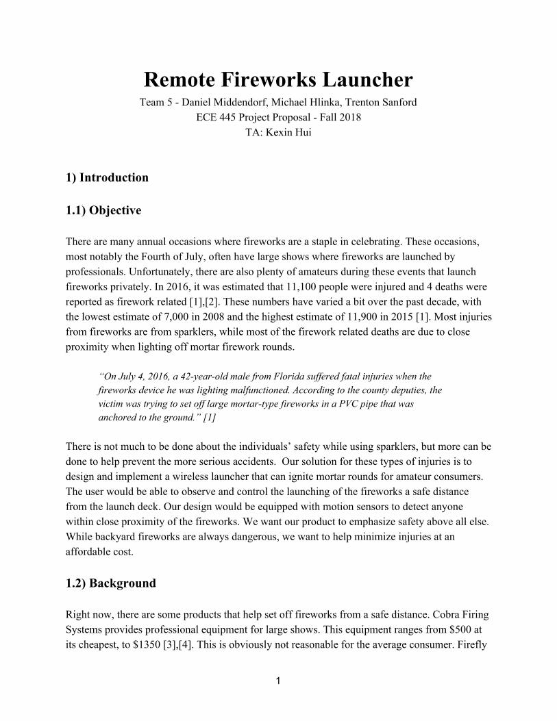
Remote Fireworks Launcher Team 5 - Daniel Middendorf, Michael Hlinka, Trenton Sanford
ECE 445 Project Proposal - Fall 2018 TA: Kexin Hui
1) Introduction 1.1) Objective There are many annual occasions where fireworks are a staple in celebrating. These occasions, most notably the Fourth of July, often have large shows where fireworks are launched by professionals. Unfortunately, there are also plenty of amateurs during these events that launch fireworks privately. In 2016, it was estimated that 11,100 people were injured and 4 deaths were reported as firework related [1],[2]. These numbers have varied a bit over the past decade, with the lowest estimate of 7,000 in 2008 and the highest estimate of 11,900 in 2015 [1]. Most injuries from fireworks are from sparklers, while most of the firework related deaths are due to close proximity when lighting off mortar firework rounds.
“On July 4, 2016, a 42-year-old male from Florida suffered fatal injuries when the fireworks device he was lighting malfunctioned. According to the county deputies, the victim was trying to set off large mortar-type fireworks in a PVC pipe that was anchored to the ground.” [1]
There is not much to be done about the individuals’ safety while using sparklers, but more can be done to help prevent the more serious accidents. Our solution for these types of injuries is to design and implement a wireless launcher that can ignite mortar rounds for amateur consumers. The user would be able to observe and control the launching of the fireworks a safe distance from the launch deck. Our design would be equipped with motion sensors to detect anyone within close proximity of the fireworks. We want our product to emphasize safety above all else. While backyard fireworks are always dangerous, we want to help minimize injuries at an affordable cost. 1.2) Background Right now, there are some products that help set off fireworks from a safe distance. Cobra Firing Systems provides professional equipment for large shows. This equipment ranges from $500 at its cheapest, to $1350 [3],[4]. This is obviously not reasonable for the average consumer. Firefly
1
Firing System offers a cheaper alternative for firework enthusiasts, at $200 [5]. While this is cheaper than the professional firing systems, there are no safety measures in place to indicate when someone may be in danger around the fireworks, or a misfire occurs. Our proposed solution would be cheaper and, more importantly, safer than what is currently available on the market. 1.3) High-level Requirements
● System must succeed in igniting fuses consistently. ● Entire launcher system must be as affordable as possible , ideally under $100. ● Reliably detect people within an 8 foot radius from the firework launch deck. ● Controller and receiver must be able to reliably communicate from at least 150 feet away.
2) Design To make this fireworks launcher complete, we designed three different parts: the user’s controller, the main receiver, and two identical sensor pods (referred to simply as pods). The controller is what the user will interact with to launch the fireworks. The receiver is where the data from the controller and pods are processed and interpreted. This is also where the fuses for the igniters will be attached. The pods are detachable units whose job is to provide different angles for the safety sensors. Each unit will have a power system that will consist of batteries and will provide the other modules with the power they need. Each unit will also require a WiFi module so that all units are able to communicate with each other. The receiver and pod units will contain sensors that detect if people are within the area and whether a successful launch happened or not. Lastly, the receiver and controller will have a control unit responsible for: displaying information, interpreting data, and deciding when to ignite a fuse.
2
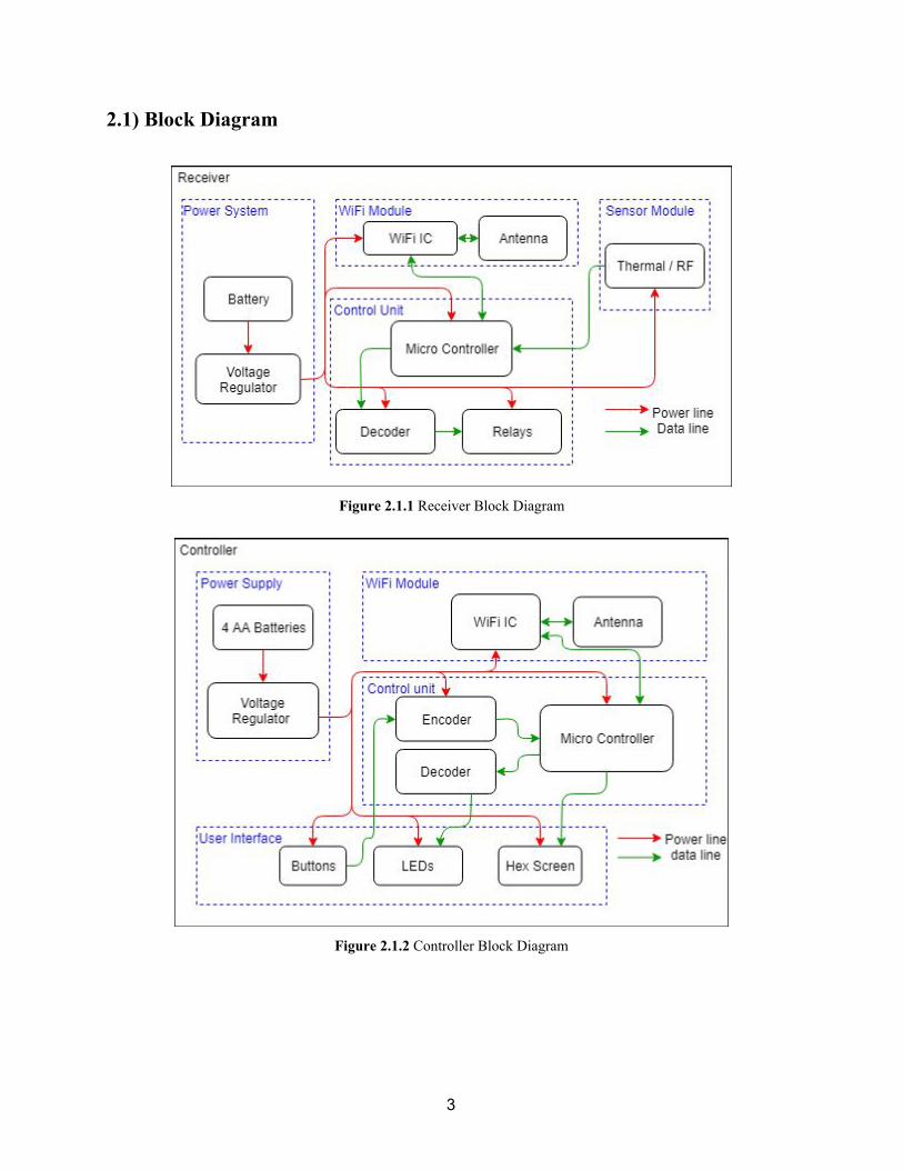
2.1) Block Diagram
Figure 2.1.1 Receiver Block Diagram
Figure 2.1.2 Controller Block Diagram
3
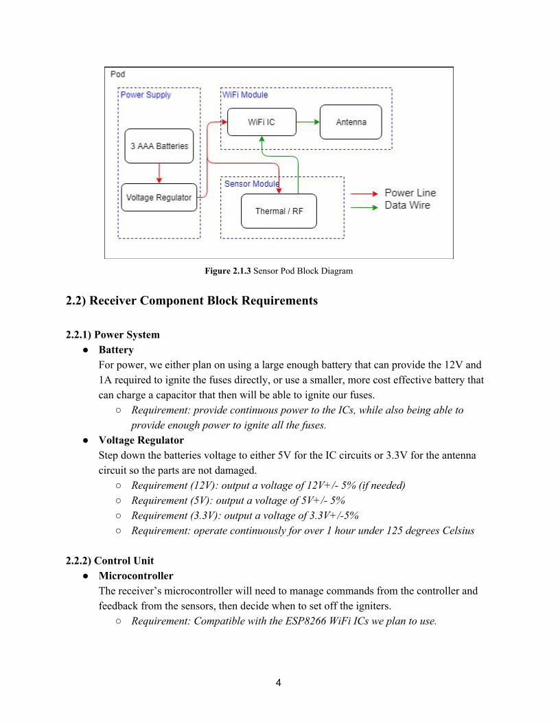
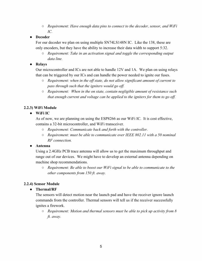
Figure 2.1.3 Sensor Pod Block Diagram
2.2) Receiver Component Block Requirements 2.2.1) Power System
● Battery For power, we either plan on using a large enough battery that can provide the 12V and 1A required to ignite the fuses directly, or use a smaller, more cost effective battery that can charge a capacitor that then will be able to ignite our fuses.
○ Requirement: provide continuous power to the ICs, while also being able to provide enough power to ignite all the fuses.
● Voltage Regulator Step down the batteries voltage to either 5V for the IC circuits or 3.3V for the antenna circuit so the parts are not damaged.
○ Requirement (12V): output a voltage of 12V+/- 5% (if needed) ○ Requirement (5V): output a voltage of 5V+/- 5% ○ Requirement (3.3V): output a voltage of 3.3V+/-5% ○ Requirement: operate continuously for over 1 hour under 125 degrees Celsius
2.2.2) Control Unit
● Microcontroller The receiver’s microcontroller will need to manage commands from the controller and feedback from the sensors, then decide when to set off the igniters.
○ Requirement: Compatible with the ESP8266 WiFi ICs we plan to use.
4
○ Requirement: Have enough data pins to connect to the decoder, sensor, and WiFi IC.
● Decoder For our decoder we plan on using multiple SN74LS148N IC. Like the 138, these are only encoders, but they have the ability to increase their data width to support 5:32.
○ Requirement: Take in an activation signal and toggle the corresponding output data line.
● Relays Our microcontroller and ICs are not able to handle 12V and 1A. We plan on using relays that can be triggered by our ICs and can handle the power needed to ignite our fuses.
○ Requirement: when in the off state, do not allow significant amount of current to pass through such that the igniters would go off.
○ Requirement: When in the on state, contain negligible amount of resistance such that enough current and voltage can be applied to the igniters for them to go off.
2.2.3) WiFi Module
● WiFi IC As of now, we are planning on using the ESP8266 as our WiFi IC. It is cost effective, contains a 32-bit microcontroller, and WiFi transceiver.
○ Requirement: Communicate back and forth with the controller. ○ Requirement: must be able to communicate over IEEE 802.11 with a 50 nominal
RF connection. ● Antenna
Using a 2.4GHz PCB trace antenna will allow us to get the maximum throughput and range out of our devices. We might have to develop an external antenna depending on machine shop recommendations.
○ Requirement: Be able to boost our WiFi signal to be able to communicate to the other components from 150 ft. away.
2.2.4) Sensor Module
● Thermal/RF The sensors will detect motion near the launch pad and have the receiver ignore launch commands from the controller. Thermal sensors will tell us if the receiver successfully ignites a firework.
○ Requirement: Motion and thermal sensors must be able to pick up activity from 8 ft. away.
5

2.3) Controller Component Block Requirements 2.3.1) Power Supply
● Batteries These batteries must be able to provide the current and voltage necessary for the other modules within the controller for one entire session of launching fireworks.
○ Requirement: Battery must be able to provide >5V for an entire launching session ● Voltage Regulator
Step down the batteries voltage to either 5V for the IC circuits or 3.3V for the antenna circuit so the parts are not damaged.
○ Requirement (5V): reduce >5V voltage to 5V+/- 5% ○ Requirement (3.3V): reduce >5V voltage to 3.3V+/-5% ○ Requirement: operate continuously for over 1 hour under 125 degrees Celsius
2.3.2) Control Unit
● Encoder For our encoder we plan on using multiple SN74F138N IC. These are only 8:3, but they have a chaining ability to increase our data width to incorporate 32 input and 5 output.
○ Requirement: when one of the 32 buttons are pressed, output that line number in binary representation along with a trigger signal.
● Microcontroller The controller’s microcontroller will manage input information from the buttons and feedback from the receiver.
○ Requirement: Compatible with the ESP8266 WiFi ICs we plan to use. ○ Requirement: Have enough data pins to connect to the encoder, decoder, and
work with the WiFi ICs. ● Decoder
For our decoder we plan on using multiple SN74LS148N IC. Like the 138, these are only encoders, but they have the ability to increase their data width to support 5:32.
○ Requirement: Take in an activation signal and toggle the corresponding output data line.
2.3.3) User Interface
● Buttons What the user will mainly be interacting with. Will start the signal when the user wishes to launch a firework.
○ Requirement: When not pushed, allow neglable current to pass through (displaying a logic level of “1”).
6
○ Requirement: When pushed, allow significant amount of current to pass through (displaying a logic level of “0”).
● LEDs
For the user to know which buttons have been pressed, these LEDs along with D-flip flops, will store and display which buttons have currently been pressed.
○ Requirement: Store and display correctly if the button has been pressed after reset and ready signals have been sent.
● Hex Screen Currently we believe that we will only need a 4-digit 7-segment display to convey the different types of error codes the user will ever encounter. Keeping it simple allows us to keep the cost down and we will only need a limited amount of unique errors.
○ Requirement: Correctly display different sets of error codes depending on the type of error encountered.
2.3.4) WiFi Module
● WiFi IC As of now, we are planning on using the ESP8266 as our WIFI IC. It is cost effective, contains a 32-bit microcontroller and WIFI transceiver.
○ Requirement: Communicate back and forth with the receiver. ○ Requirement: must be able to communicate over IEEE 802.11 with a 50 nominal
RF connection. ● Antenna
Using a 2.4GHz PCB trace antenna will allow us to get the maximum throughput and range out of our devices. We might have to develop an external antenna depending on machine shop recommendations.
○ Requirement: Be able to boost our WiFi signal to be able to communicate to the other components from 150 ft. away.
2.4) Sensor Pod Component Block Requirements 2.4.1) Power Supply
● Batteries For the pods we decided on using 3 AAA batteries. These batteries are small enough to fit inside our pods while still giving us room for everything else and they will be able to provide a large enough voltage to power our WiFi IC.
○ Requirement: Provide >3.3V and enough current to power the WiFi IC and sensors.
7

● Voltage Regulator The WiFi IC requires a 3.3V source to power it, so the voltage regulator must be able to provide that within a tolerable range.
○ Requirement: Make the input voltage for the WiFi IC 3.3V +/-5%. 2.4.2) WiFi Module
● WiFi IC As of now, we are planning on using the ESP8266 as our WiFi IC. It is cost effective, contains a 32-bit microcontroller and WiFi transceiver.
○ Requirement: Communicate back and forth with the receiver. ○ Requirement: must be able to communicate over IEEE 802.11 with a 50 nominal
RF connection. ● Antenna
Using a 2.4GHz PCB trace antenna will allow us to get the maximum throughput and range out of our devices. We might have to develop an external antenna depending on machine shop recommendations.
○ Requirement: Be able to boost our WiFi signal to be able to communicate to the other components from 150 ft. away.
2.4.3) Sensor Module
● Thermal/RF The sensors will detect motion near the launch pad and have the receiver ignore launch commands from the controller. Thermal sensors will tell us if the receiver successfully ignited a firework.
○ Requirement: Motion and thermal sensors must be able to pick up activity from 8 ft. away.
2.5) Physical Design Since we are making a product that is not reliant on other hardware (other than disposable fuses), physical designs were necessary. Since we needed to develop three different systems to house our different components, we needed to create three different physical devices. We knew that the biggest electronic component in our project is going to be the receiver PCB. After discussing the design for a while, we came up with the design in figure 2.5.1 because it allowed us enough room to comfortably fit all the components within the receiver block without having to try and squeeze parts together. We are not completely set on exactly how our devices will end up looking, but we were able to develop the basic shapes and how most of the parts will be
8
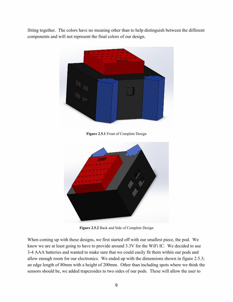
fitting together. The colors have no meaning other than to help distinguish between the different components and will not represent the final colors of our design.
Figure 2.5.1 Front of Complete Design
Figure 2.5.2 Back and Side of Complete Design
When coming up with these designs, we first started off with our smallest piece, the pod. We knew we are at least going to have to provide around 3.3V for the WiFi IC. We decided to use 3-4 AAA batteries and wanted to make sure that we could easily fit them within our pods and allow enough room for our electronics. We ended up with the dimensions shown in figure 2.5.3; an edge length of 80mm with a height of 200mm. Other than including spots where we think the sensors should be, we added trapezoides to two sides of our pods. These will allow the user to
9
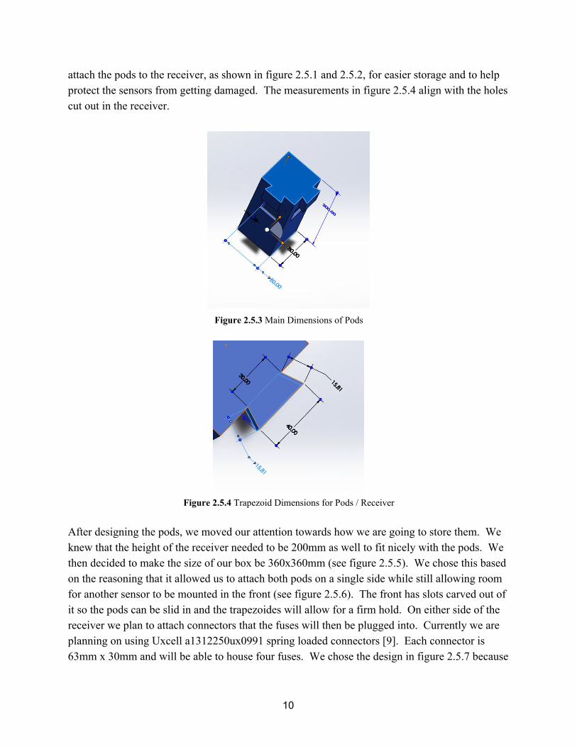
attach the pods to the receiver, as shown in figure 2.5.1 and 2.5.2, for easier storage and to help protect the sensors from getting damaged. The measurements in figure 2.5.4 align with the holes cut out in the receiver.
Figure 2.5.3 Main Dimensions of Pods
Figure 2.5.4 Trapezoid Dimensions for Pods / Receiver
After designing the pods, we moved our attention towards how we are going to store them. We knew that the height of the receiver needed to be 200mm as well to fit nicely with the pods. We then decided to make the size of our box be 360x360mm (see figure 2.5.5). We chose this based on the reasoning that it allowed us to attach both pods on a single side while still allowing room for another sensor to be mounted in the front (see figure 2.5.6). The front has slots carved out of it so the pods can be slid in and the trapezoides will allow for a firm hold. On either side of the receiver we plan to attach connectors that the fuses will then be plugged into. Currently we are planning on using Uxcell a1312250ux0991 spring loaded connectors [9]. Each connector is 63mm x 30mm and will be able to house four fuses. We chose the design in figure 2.5.7 because
10
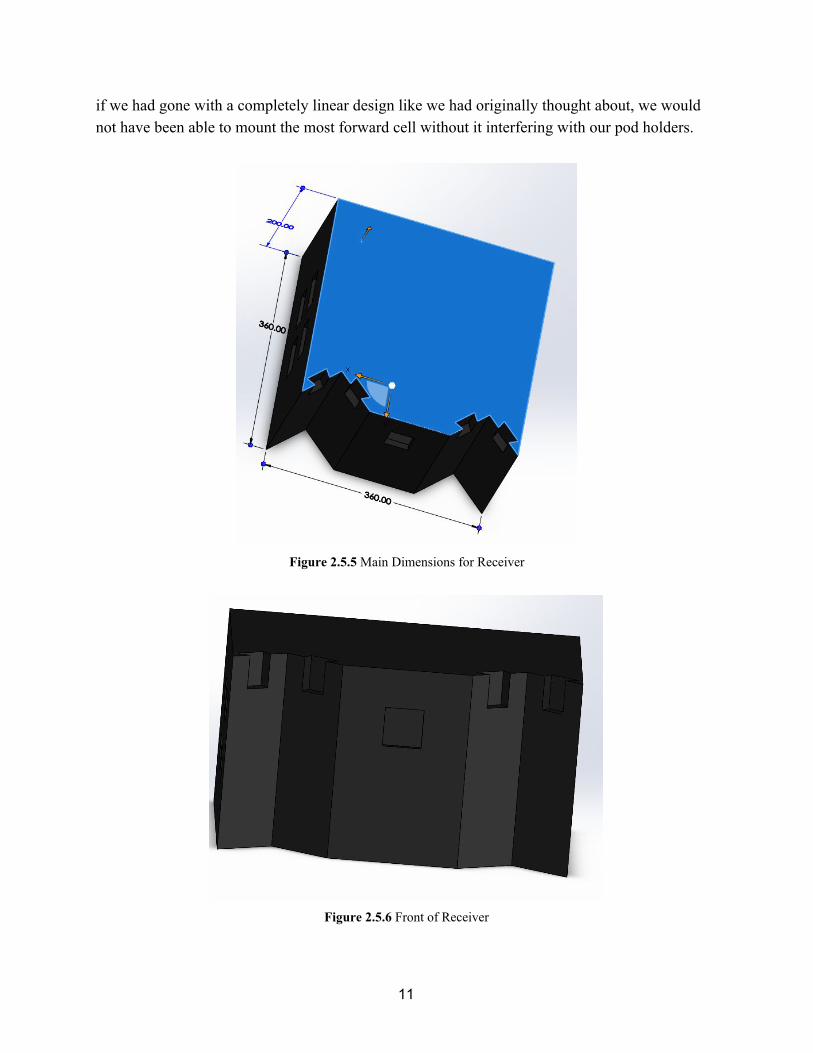
if we had gone with a completely linear design like we had originally thought about, we would not have been able to mount the most forward cell without it interfering with our pod holders.
Figure 2.5.5 Main Dimensions for Receiver
Figure 2.5.6 Front of Receiver
11
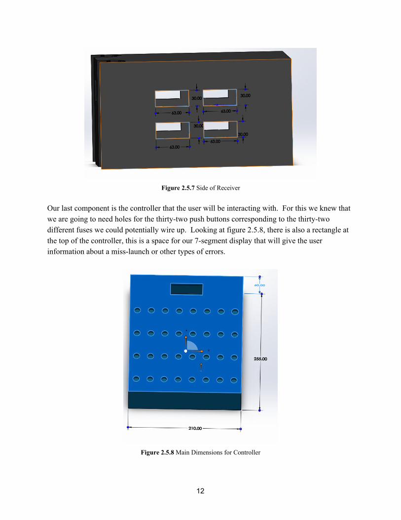
Figure 2.5.7 Side of Receiver
Our last component is the controller that the user will be interacting with. For this we knew that we are going to need holes for the thirty-two push buttons corresponding to the thirty-two different fuses we could potentially wire up. Looking at figure 2.5.8, there is also a rectangle at the top of the controller, this is a space for our 7-segment display that will give the user information about a miss-launch or other types of errors.
Figure 2.5.8 Main Dimensions for Controller
12
2.6) Risk Analysis The wireless component of our design is a critical part of our project and we believe this is the component would be most prone to failure. Our project is built around all of its components being able to quickly and reliably communicate with each other. The inability to remotely send launch signals and get reliable data from our sensors would make all of our added safety features useless. Our inexperience with wireless protocols and having to manage information from 4 different WiFi ICs is what has us most worried about this project. 3) Ethics and Safety 3.1) Ethics Due to the nature of our project there are some ethical, and legal concerns to take into account. The primary use of this project is to safely ignite pyrotechnic products, specifically mortar fireworks. When using these products, federal and local laws/policies should be strictly followed. The use of fireworks is regulated federally and are illegal in the state of Illinois, including the city of Urbana, without a proper permit. However, smaller pyrotechnic devices such as sparklers, smoke devices, or trick noise makers can be legally used in Illinois without any kind of permit. More details about these laws can be found in Illinois’ Pyrotechnic Use Act [7] and the city of Urbana’s firework policies [8]. For the purposes of testing and demonstration, we only intend to use our project to ignite fuses that would normally be attached to fireworks. These fuses will not be attached to any combustible or explosive device. Even when used legally, the pyrotechnic devices can still be dangerous. The primary purpose of our project is to promote safety and attempt to minimize such risk (aligning with the first clause of the IEEE Code of Ethics [6]), however our built in safety measures aren’t foolproof; external forces and improper usage can result in the harm to the user, property, and others. For example, strong winds could knock a firework tube over while being ignited such that the user, or project itself, is in the line of fire. The device could also be used maliciously to harm someone or their property. This could be in violation of the ninth clause of the IEEE Code of Ethics [6]. We intend to circumvent this by providing a specific procedure on how the project should be used to ignite pyrotechnic products and that it shouldn’t be used in adverse weather conditions.
13

3.2) Safety Considering our wireless design for interfacing between the controller and receiver, it is possible for our receiver to pick up unintended launch commands. This would obviously result in a safety issue, so we’re planning on implementing a protocol such that the receiver can only be wirelessly paired with one controller at a time and that it is the only device that can send valid launch commands. Electrocution during circuit construction and testing while developing this project is also a concern. Since we are going to be dealing with a significant amount of current and voltage, creating a short could seriously damage lab equipment, other students, and us. There is also the potential to harm ourselves and others while using the soldering irons in the lab. Properly following campus lab safety procedures and taking soldering training will help reduce these risks.
14

4) References [1] U.S. Consumer Product Safety Commission, ‘2016 Fireworks Annual Report’, 2017.
[Online]. Available: https://www.cpsc.gov/s3fs-public/Fireworks_Report_2016.pdf?t.YHKjE9bFiabmirA.4NJJST.5SUWIQJ [Accessed: 19- Sept- 2018]
[2] Andrew G. Simpson, ‘Facts About Fireworks: 11,000 Injuries, 4 Deaths in 2016’, Insurance Journal, 2017. [Online]. Available: https://www.insurancejournal.com/news/national/2017/06/30/456213.htm [Accessed: 19- Sept- 2018]
[3] Cobra Firing Systems, ‘Handheld Remotes’, [Online]. Available: http://www.cobrafiringsystems.com/remote.html [Accessed: 19- Sept- 2018]
[4] Cobra Firing Systems, ‘Modules’, [Online]. Available: http://www.cobrafiringsystems.com/modules.html [Accessed: 19- Sept- 2018]
[5] Firefly, ‘Product Details’, 2018. [Online]. Available: https://shootfirefly.com/pages/product-details [Accessed: 19- Sept- 2018]
[6] IEEE.org, ‘IEEE Code of Ethics’, 2018. [Online]. Available: https://www.ieee.org/about/corporate/governance/p7-8.html [Accessed: 15- Sept- 2018]
[7] Illinois General Assembly, ‘(425 ILCS 35/) Pyrotechnic Use Act’, 2009. [Online]. Available: http://www.ilga.gov/legislation/ilcs/ilcs3.asp?ActID=1635&ChapterID=38 [Accessed: 15- Sept- 2018]
[8] City of Urbana, ‘Fireworks’, 2009. [Online]. Available: https://www.urbanaillinois.us/residents/fire-safety/fireworks [Accessed: 15- Sept- 2018]
[9] Amazon, ‘Uxcell a13122500ux0991 8 Pin Spring Loaded Speaker Terminals Board Connector 63mm x 30mm (Pack of 5)’, 2018. [Online]. Available: https://www.amazon.com/Uxcell-a13122500ux0991-Speaker-Terminals-Connector/dp/B00K800X2M/ref=pd_sbs_23_15?_encoding=UTF8&pd_rd_i=B00K800X2M&pd_rd_r=e0843270-b9d6-11e8-87eb-1be919d0e38f&pd_rd_w=c10wC&pd_rd_wg=kjFbh&pf_rd_i=desktop-dp-sims&pf_rd_m=ATVPDKIKX0DER&pf_rd_p=53dead45-2b3d-4b73-bafb-fe26a7f14aac&pf_rd_r=BQCWFD9AD99JFFXKR3G3&pf_rd_s=desktop-dp-sims&pf_rd_t=40701&psc=1&refRID=BQCWFD9AD99JFFXKR3G3
15