Embed Size (px)
Citation preview

Thank you for purchasing this JVC product.
Before beginning to operate this unit�please read
the instructions
carefully to ensure the best possible performance.
For Customer Use�
Enter below the Serial No. which is located on the
body.
Retain this information for future reference.
Model No.
Serial No.
REMOTE CONTROL PANEL
RM-LP25U INSTRUCTIONS
LST0594-001A
-3dB
-6dB
ALC
LOLUX
VARIABLELEVEL
LEVEL
LEVEL
GAMMA
DETAILKNEE POINT
AUTOKNEE
BLACKCOMPRESSSTRETCH
WHITE BALANCE MODE
WHITE PAINT
R
RBLACK PAINT
B
B
PAINT
PAINT
AUTO WHITE
AUTO BLACK
AUTO
OVER
OPEN
UNDER
CLOSE
MASTERBLACK
TALLYCALL
PREVIEW
1
OPERATE
BARS
LOCKPART
OFFFULL
SCENE FILE
2
3
5
4
SPEED
PART
SHUTTER
NORMAL 1/1001/120
1/250
1/500
1/10001/2000GAIN
18dB
0dB
3dB
6dB
9dB
12dB
15dB
MANUALPRESET
FAW
AW A
AW B
PART
PRESETLEVEL
IRIS MODEFULLPRESET
FULL
VARIABLE

2
Getting Started
1. Read all of these instructions.
2. Save these instructions for later use.
PORTABLE CART WARNING(symbol provided by RETAC)
S3125A
IMPORTANT SAFEGUARDS
4. Unplug this appliance system from the wall outlet before cleaning. Do not use liquid cleaners or aerosol
cleaners. Use a damp cloth for cleaning.
5. Do not use attachments not recommended by the appliance manufacturer as they may cause hazards.
6. Do not use this appliance near water - for example, near a bathtub, washbowl,kitchen sink, or laundry tub, in a wet
basement, or near a swimming pool, etc.
7. Do not place this appliance on an unstable cart, stand, or table. The appliance may fall,
causing serious injury to a child or adult, and serious damage to the appliance.
Use only with a cart or stand recommended by the manufacturer, or sold with the appliance.
Wall or shelf mounting should follow the manufacturer�s instructions, and should use a
mounting kit approved by the manufacturer. An appliance and cart combination should be
moved with care.
Quick stops, excessive force, and uneven surfaces may cause the appliance and cart
combination to overturn.
8. Slots and openings in the cabinet and the back or bottom are provided for ventilation, and to insure reliable operation of
the appliance and to protect it from overheating, these openings must not be blocked or covered. The openings should
never be blocked by placing the appliance on a bed, sofa, rug, or other similar surface.
This appliance should never be placed near or over a radiator or heat register.
This appliance should not be placed in a built-in installation such as a bookcase unless proper ventilation is provided.
9. This appliance should be operated only from the type of power source indicated on the marking label. If you are not sure
of the type of power supplied to your home, consult your dealer or local power company. For appliance designed to
operate from battery power, refer to the operating instructions.
10. For added protection for this product during a lightning storm, or when it is left unattended and unused for long periods
of time, unplug it form the wall outlet and disconnect the antenna or cable system. This will prevent damage to the
product due to lightning and power-line surges.
These are general IMPORTANT SAFEGUARDS and certain items may not apply to all appliances.
3. All warnings on the product and in the operating instructions should be adhered to.
FOR USA
14. Never push objects of any kind into this appliance through cabinet slots as they may touch dangerous voltage points or
short out parts that could result in a fire or electric shock. Never spill liquid of any kind on the appliance.
15. Do not attempt to service this appliance yourself as opening or removing covers may expose you to dangerous voltage
or other hazards. Refer all servicing to qualified service personnel.
16. Unplug this appliance from the wall outlet and refer servicing to qualified service personnel under the following conditions:
a.When the power cord or plug is damaged or frayed.b. If liquid has been spilled into the appliance.
c. If the appliance has been exposed to rain or water.
d.
e. If the appliance has been dropped or the cabinet has been damaged.
f.
If the appliance does not operate normally by following the operating instructions. Adjust only those controls that
are covered by the operating instructions as improper adjustment of other controls may result in damage and will
often require extensive work by a qualified technician to restore the appliance to normal operation.
When the appliance exhibits a distinct change in performance - this indicates a need for service.
17. When replacement parts are required, be sure the service technician has used replacement parts specified by the
manufacturer that have the same characteristics as the original part. Unauthorized substitutions may result in fire,
electric shock, or other hazards.
18. Upon completion of any service or repairs to this appliance, ask the service technician to perform routine safety checks
to determine that the appliance is in safe operating condition.
13. Do not overload wall outlets and extension cords as this can result in fire or electric shock.
12. Follow all warnings and instructions marked on the appliance.
11. Do not allow anything to rest on the power cord. Do not locate this appliance where the cord will be abused by persons
walking on it.
3
Safety Precautions
CAUTION:
RISK OF ELECTRIC SHOCKDO NOT OPEN
CAUTION
FOR USA AND CANADA
TO REDUCE THE RISK OF ELECTRICSHOCK. DO NOT REMOVE COVER (ORBACK).NO USER-SERVICEABLE PARTSINSIDE.REFER SERVICING TO QUALIFIEDSERVICE PERSONNEL.
The lightning flash wish arrowhead symbol,
within an equilateral triangle is intended to
alert the user to the presence of uninsulated
�dangerous voltage� within the product's
enclosure that may be of sufficient magnitude
to con-stitute a risk of electric shock to
persons.
The exclamation point within an equilateral
triangle is intended to alert the user to the
presence of important operating and
maintenance (servicing) instructions in the
literature accompanying the appliance.
Information for USA
INFORMATION�This equipment has been tested and found to comply withthe limits for a Class A digital device, pursuant to Part 15 ofthe FCC Rules.These limits are designed to provide reasonable protectionagainst harmful interference when the equipment isoperated in a commercial environment.This equipment generates, uses, and can radiate radiofrequency energy and, if not installed and used inaccordance with the instruction manual, may cause harmfulinterference to radio communications.Operation of this equipment in a residential area is likely tocause harmful interference in which case the user will berequired to correct the interference at his own expense.
CAUTION�CHANGES OR MODIFICATIONS NOT APPROVED BY JVCCOULD VOID USER fS AUTHORITY TO OPERATE THEEQUIPMENT.
NOTE�
The rating plate (serial number plate) is on this unit.
WARNING�TO REDUCE THE RISK OF FIRE OR ELECTRIC SHOCK,DO NOT EXPOSE THIS APPLIANCE TO RAIN ORMOISTURE.
THIS DEVICE COMPLIES WITH PART 15 OF THE FCCRULES.OPERATION IS SUBJECT TO THE FOLLOWING TWOCONDITIONS: (1) THIS DEVICE MAY NOT CAUSEHARMFUL INTERFERENCE, AND (2) THIS DEVICE MUSTACCEPT ANY INTERFERENCE RECEIVED, INCLUDINGINTERFERENCE THAT MAY CAUSE UNDESIREDOPERATION.
This unit should be used with 9 V DC only.
Cet appareil num rique de la Classe A est conforme á la norme
NMB-003 du Canada.
INFORMATION (FOR CANADA)
RENSEIGNEMENT (POUR CANADA)
This Class A digital apparatus complies with Canadian ICES-003.
Due to design modifications, data given in this instruction book
are subject to possible change without prior notice.
AVERTISSEMENT:POUR EVITER LES RISQUESD�INCENDIE OU D�ELECTROCUTION, NE PASEXPOSER L�APPAREIL A L�HUMIDITE OU A LAPLUIE.
WARNING:TO REDUCE THE RISK OF FIRE OR ELECTRICSHOCK, DO NOT EXPOSE THIS APPLIANCE TO
RAIN OR MOISTURE.
This unit should be used with 9V DC only.
CAUTION:To prevent electric shocks and fire hazards, do NOT use any
other power source.
NOTE:The rating plate �serial number plate) is on the side of the unit.
REMARQUE:La plaque signalétique �plaque du numéro de série) se trouve
sur la paroi latérale de l’appareil.
CAUTION:To prevent electric shock, do not open the cabinet. No userserviceable parts inside. Refer servicing to qualified servicepersonnel.
The apparatus shall not be exposed to dripping or splashing and
that no objects filled with liquids, such as vases, shall be placed
close to the apparatus.
Ce magnétoscope ne doit être utilisé que sur du courant
direct en 9V.
ATTENTION:
Afin d’eviter tout resque d’incendie ou d’electrocution, ne
pas utillser d’autres sources d’alimentation électrique.

4
Getting Started
Safety Precautions (continued)
CableMaximum Cable
Length
REMOTE CABLE Shielded Cable 5 m
PREVIEW Shielded Cable 3 m
TALLY(PVM) Shielded Cable 3 m
TALLY(PGM) Shielded Cable 3 m
GND Shielded Cable 3 m
FOR EUROPE
This equipment is in conformity with the provisions and protectionrequirements of the corresponding European Directives. Thisequipment is designed for professional video appliances and canbe used in the following environments:
In order to keep the best performance and furthermore forelectromagnetic compatibility we recommend to use cables notexceeding the following lengths:
� Controlled EMC environment �for example, purpose-builtbroadcasting or recording studio), and rural outdoorsenvironments.
Caution�
Where there are strong electromagnetic waves or magnetism� forexample near a radio or TV transmitter� transformer� motor� etc.�the picture and the sound may be disturbed. In such case� pleasekeep the apparatus away from the sources of the disturbance.
Dear Customer�This apparatus is in conformance with the valid European directives and
standards regarding electromagnetic compatibility and electrical safety.
European representative of Victor Company of Japan Limited.is:
JVC Technology Centre Europe GmbH
P.O.Box 10 05 52
61145 Friedberg
Germany
Information for Users on Disposal of Old Equipment
[European Union]
Attention:
This symbol indicates that the electrical and electronic
equipment should not be disposed as general household
waste at its end-of-life. Instead� the product should be handed
over to the applicable collection point for the recycling of
electrical and electronic equipment for proper treatment�
recovery and recycling in accordance with your national
legislation.
By disposing of this product correctly� you will help to conserve
natural resources and will help prevent potential negative
effects on the environment and human health which could
otherwise be caused by inappropriate waste handling of this
product. For more information about collection point and
recycling of this product� please contact your local municipal
office� your household waste disposal service or the shop
where you purchased the product. Penalties may be applicable
for incorrect disposal of this waste� in accordance with national
legislation.
�Business users)If you wish to dispose of this product� please visit our web
page www.jvceurope.com to obtain information about the
take-back of the product.
[Other Countries outside the European Union]
If you wish to dispose of this product� please do so in
accordance with applicable national legislation or other rules
in your country for the treatment of old electrical and
electronic equipment.
This symbol isonly valid in the European
Union.
��
��

5
This product is a remote control panel for controlling HD
CAMERA RECORDER(GY-HD250/GY-HD251/GY-HD200/
GY-HD201).
Scene File Feature
You can assign different settings to each of the five Scene
File buttons and save them accordingly.
This is useful at job sites where speed is required, as you
can recall the settings according to the shooting conditions
by pressing the relevant button.
Self-illuminating Indicator
Buttons that are enabled are indicated in green, allowing you
to identify the usable features easily.
A button that is selected lights up in orange, allowing you to
identify the current camera settings easily.
In addition, the buttons and switches are also appropriately
arranged according to their frequency of use.
Iris F-value Display
The iris F-value of the camera is indicated on the remote
control.
This enables you to perform accurate adjustment by grasping
the iris condition at real-time.
Location of Storage and Use
� Do not place this product at the following locations.
Doing so may cause the product to malfunction or break down.
� Hot or cold places beyond the allowable operating
temperature range of -5 �C to +40 �C.
� Humid places beyond the allowable humidity range of
30 % RH to 80 % RH (non-condensing).
� Places in the vicinity of a strong magnetic field, such as
near transformers or motors.
� Near equipment that emit radio waves, such as
transceivers or mobile phones.
� Places that are subject to dust or sand.
� Places that are subject to strong vibrations.
� Places that are susceptible to condensation, such as
near windows.
� Places that are subject to vapor or oil, such as kitchens.
� Places that emit radioactive rays or X-rays, and corrosive gases.
� Noise may occur in the images or their colors may change
when this product and the cable that is used to connect it are
used at a place that is subject to strong radio or magnetic
waves (e.g., near radios, TVs, transformers, or monitors).
Handling Precautions
� Insufficient ventilation may result in malfunction of this
product. Make sure that objects placed around this
product do not obstruct its ventilation.
� Do not place containers with water (e.g. vases, flower pots, cups,
toiletry products, or chemicals) on top of this product. Moisture
that enters this product may cause fire or electric shock.
Moving the Product
� Remove connection cables before moving this product
When moving this product, do so after turning off the
power of the connected camera, and make sure that you
unplug the cable from the camera. Failure to do so may
damage the cable or cause fire or electric shock.
Maintenance
� Turn off the power of the connected camera before
performing maintenance of this product.
� Use a soft cloth to wipe the product. Do not wipe using
thinner or benzene, as doing so may cause the surface to
melt or turn cloudy. When there is significant soiling, wipe
using a cloth by dipping it in a neutral detergent that is
diluted with water, followed by cleaning using a dry cloth.
Energy Conservation
� When this product is not to be used for a prolonged period
of time, turn of the power of the system for safety and
energy conservation purposes.
Features
How to read this manual
� Definition of Symbols
Note : Precautions that need to be taken during
operation.
Memo : Details for reference, such as features and
restrictions during use.
A : Page or item to refer to.
� Descriptions in this manual
� The copyright of this manual belongs to Victor Company
of Japan, Limited. Reproduction or duplication of a part
or the whole of this manual without permission is
prohibited.
� Product names of other companies contained in this
manual are the trademark or registered trademark of the
respective companies. Symbols such as �, �, and � are
omitted in this manual.
� Designs, specifications, and other details contained in
this manual may be modified for improvement without
prior notice.
Precautions During Use

6
Getting Started
Getting Started
Safety Precautions ............................................................. 3
Features ............................................................................. 5
Precautions During Use ..................................................... 5
Table of Contents ............................................................... 6
Names and Functions of Parts ........................................... 7
Control Panel .................................................................. 7
Rear/Side of Remote Control Panel .............................. 13
Operation
Exemplary System ........................................................... 14
Setup ................................................................................ 14
Shutter Settings ................................................................ 15
Gain Settings .................................................................... 16
White Balance Adjustment ............................................... 17
Automatic Adjustment ................................................... 17
Manual Adjustment ....................................................... 17
Black Balance Adjustment ................................................ 18
Automatic Adjustment ................................................... 18
Manual Adjustment ....................................................... 18
Scene File ........................................................................ 19
Storing a New Scene File ............................................. 19
Loading a Scene File .................................................... 20
Clearing a Scene File ................................................... 20
List of Supported Features in Scene Files .................... 21
Adjustment of Indicator's Brightness ................................ 22
Input/Output of Rear Ports ............................................... 22
Tally Input Terminal ....................................................... 23
PREVIEW Output Terminal ........................................... 23
Setting Selection DIP Switch ............................................ 24
Operable Features ........................................................... 25
Operation of Connected Camera ..................................... 26
Remote Connector Specifications .................................... 26
Others
Troubleshooting ................................................................ 27
Specifications ................................................................... 27
Table of Contents

7
Control Panel
A [LOCK]Operation Lock Switch
An operation may be locked to maintain the settings. There
are three different lock modes as indicated below.
Note:
� When in the [PART] or [FULL] mode, ON/OFF operation
using the Operate button B is also disabled.
Names and Functions of Parts
-3
LEVEL LEVELGAMMA DETAIL KNEE POINT AUTOKNEE
BLACK
COMPRESS STRETCH
R
R
PAINT
PAINT
AUTO WHITE
AUTO BLACK
AUTO
OVER OPEN
UN CLOSE
STERACK
TALLY
CALL PREVIEW
1
OPERATE BARSLOCKPART
OFF FULL
SCENE FILE
2 3 54
SPEED
PARTR
NOR 1/1000 1/20
0
W A AW B
PART
SET
FULL
B
E
G
C
H
O
R
S
�
P
Q
F
RPA NT AUTO BLACK
-3
0
SPEED
R
NOR 1/1000 1/20
PART
RPA NT AUTO WH TE
W A AW B
AUTO
OVER OPEN
UN CLOOSSSE
STERACK
PART
SET
E
PART
N
D
I
J
L
M
K
Indicator light:
For features that make use of self-illuminating buttons,
features available on the connected camera are checked
and displayed during communication to verify connection
with the camera (initial communication).
T However, this excludes the [OPERATE], [SCENE FILE 1
to 5], and [PREVIEW] buttons.
Orange light on : Currently selected.
Green light on : Not selected but available for selection.
Light off : Feature is not available on the camera
and cannot be selected.
Memo: � The light is turned off if a feature is available on the
camera but disabled due to the settings of this product.
Memory function:
This unit has a memory function that will memorize the
value of switch and knob, which have been set once.
(excluding [IRIS MODE] switch K and [IRIS/AUTO IRIS
LEVEL] setting lever M)
As such, when setting [OPERATE] button to ON, it will
operate with previous settings even if the position of the
knobs is different from the previous use. However, rotating
the knobs when knob operation is enabled will cancel the
memory and settings will be changed to the actual position
of the knobs.
[OFF] Lock is turned off, and all features are
enabled.
[PART] Only those features in the bold frame
indicated as �PARTB and �FULLB on the
control panel are enabled. Other features are
locked with the current settings on the remote
control remaining valid.
The following features are enabled.
D[SHUTTER] control unit
E[GAIN] control unit
K[IRIS] control unit
M[IRIS/AUTO IRIS LEVEL] setting lever
N[MASTER BLACK] knob
P[CALL] Button
Q[PREVIEW] Button
[FULL] Only buttons in the bold frame indicated as
�FULLB are enabled. Other features are
locked with the current settings on the remote
control remaining valid. The following features
are enabled.
P[CALL] Button
Q[PREVIEW] Button

8
Getting Started
Control Panel (continued)
B [OPERATE]Operate Button and Indicator Light
C [SCENE FILE 1 to 5]Scene File Button and Indicator
Light(A 19 page)
For storing the scene file data and loading/clearing the
preset scene file data.
D [SHUTTER]Shutter Speed Control Unit(A 15 page)
For specifying the shutter settings.
E [GAIN]Gain Control Unit(A 16 page)
For specifying the gain settings.
F [DETAIL]/[LEVEL] Detail Control Unit
[DETAIL] Detail button and indicator light:
For turning ON/OFF the detail (contour) enhancement level
control.
[LEVEL] level adjustment knob:
For adjusting the detail level.
Note:
� The feature is not available on the camera if the light of
the corresponding button is not lit. Control using this unit
is disabled in this case.
G [GAMMA]/[LEVEL] Gamma Control Unit
[GAMMA] Gamma button and indicator light:
For turning ON/OFF the gamma level control.
Names and Functions of Parts (continued)
-3
LEVEL LEVELGAMMA DETAIL KNEE POINT AUTOKNEE
BLACK
COMPRESS STRETCH
R
R
PAINT
PAINT
AUTO WHITE
AUTO BLACK
AUTO
OVER OPEN
UN CLOSE
STERACK
TALLY
CALL PREVIEW
1
OPERATE BARSLOCKPART
OFF FULL
SCENE FILE
2 3 54
SPEED
PARTR
NOR 1/1000 1/20
0
W A AW B
PART
SET
FULL
B
E
G
C
H
O
R
S
�
P
Q
F
RPA NT AUTO BLACK
-3
0
SPEED
R
NOR 1/1000 1/20
PART
RPA NT AUTO WH TE
W A AW B
AUTO
OVER OPEN
UN CLOOSSSE
STERACK
PART
SET
E
PART
N
D
I
J
L
M
K
ON
(Orange light on)
Control of the camera using this
unit is enabled.
OFF (Light off) Control of the camera using this
unit is disabled.
ON
(Orange light on)
Control of the detail level using
this unit is enabled.
Adjust by turning the [LEVEL]
knob.
OFF
(Green light on)
Control of the detail level using
this unit is disabled.
The detail level is set to the
camera's standard value.
ON
(Orange light on)
Control of the gamma level using
this unit is enabled.
Adjust by turning the [LEVEL]
knob.
OFF
(Green light on)
Control of the gamma level using
this unit is disabled.
The gamma level is set to the
camera's standard value.
LEVEL DETAIL
Softens the outline. Sharpens the outline.

9
[LEVEL] level adjustment knob:
For adjusting the gamma level.
Note:
� The feature is not available on the camera if the light of
the corresponding button is not lit. Control using this unit
is disabled in this case.
H [BLACK] Black Control Unit
For switching the gain value of dark areas. Switch using the
video signals to be shot.
[STRETCH] Stretch button:
Enhances the contrast of dark areas in an image by
stretching only the signals of the dark areas.
[COMPRESS] Compress button:
Compresses the gain value of dark areas to enhance the
contrast when the image shot is bright and has little contrast.
Memo: � When both buttons light up in green, or when one button
lights up in green and the other is not lit, the setting
becomes �NORMALB (no correction).
Note:
� The feature is not available on the camera if the light of
the corresponding button is not lit. Control using this unit
is disabled in this case.
I White Balance Control Unit (A 17 page)
For specifying the white balance settings.
� [WHITE BALANCE MODE] White Balance Mode
selection button
For setting the white balance mode.
The indicator of the selected mode lights up in orange.
� [AUTO WHITE] Auto White button
Pressing this button when [WHITE BALANCE MODE] is set
to �AW AB or �AW BB lights up the button in orange and
starts up the auto white feature.
After the adjustment is complete, the result is indicated by
the indicator.
Note:
� When [WHITE BALANCE MODE] is set to �MANUALB,
�PRESETB, or �FAWB, this button is not lit, and auto white
does not start up.
� Setting the [BARS] button S to �ONB outputs a color bar
image. In this case, this button is not lit, and auto white
does not start up.
� [PAINT] Paint button and indicator light:
When [WHITE BALANCE MODE] is set to �AW AB or �AW
BB, you can specify whether fine-tuning on the value stored
at the camera is to be performed.
In addition, when [WHITE BALANCE MODE] is set to
�MANUALB, the orange light turns on, and adjustment of the
R/B channel's gain value using the [WHITE PAINT R/B] knob
is enabled.
Note:
� After the auto white operation is complete, this button is
indicated as �OFFB (green light on).
� When [WHITE BALANCE MODE] is set to�PRESETB or
�FAWB, this button is not lit, and the [WHITE PAINT R/B]
knob control is disabled.
� [WHITE PAINT R/B]White Paint R/B adjustment knob:
The functions available differs according to the white balance
mode button selected.
Memo: � You can select the corresponding white balance mode
button to store settings for �MANUALB, �AW AB, and �AW
BB respectively.
Setting Value Function
MANUAL White balance value that is set using the
White Paint R/B adjustment knob is used.
PRESET The preset white balance value (3200K) is
used.
FAW Switches to the FAW (Full-time Auto White
Balance) mode, and white balance is
automatically adjusted to an appropriate
value.
AW A The value stored in the camera's auto
white balance memory A or B is used. AW B
LEVEL G�MM�
Decreases the
reproducibility of dark
areas.
Enhances the
reproducibility of dark
areas.
Lights up in green Auto white is successfully
completed.
Blinks in orange B Lights up in green
Auto white is abnormally
terminated.
ON
(Orange light on)
Fine-tuning enabled.
Adjust by turning the [WHITE
PAINT R/B] knob.
OFF
(Green light on)
Fine-tuning disabled.
The [WHITE PAINT R/B] knob is
disabled.
Setting of
White Balance
Mode
Selection
Button
Feature of White Paint
Knob
Status of
Paint
Indicator
Light
MANUAL Knob for adjusting the R/B
channel's gain value.
Lit
PRESET/FAW Disabled. Not lit
AW A Knob for fine-tuning the
white balance value
obtained during auto
white balance adjustment.
Lit
AW B
1�
Getting Started
Control Panel (continued)
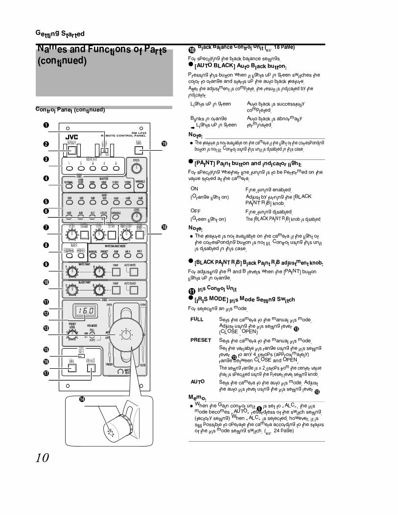
J Black Balance Control Unit (A 18 page)
For specifying the black balance settings.
� [AUTO BLACK] Auto Black button:
Pressing this button when it lights up in green switches the
color to orange and starts up the auto black feature.
After the adjustment is complete, the result is indicated by the
indicator.
Note:
� The feature is not available on the camera if the light of the corresponding
button is not lit. Control using this unit is disabled in this case.
� [PAINT] Paint button and indicator light:
For specifying whether fine-tuning is to be performed on the
value stored at the camera.
Note:
� The feature is not available on the camera if the light of
the corresponding button is not lit. Control using this unit
is disabled in this case.
� [BLACK PAINT R/B] Black Paint R/B adjustment knob:
For adjusting the R and B levels when the [PAINT] button
lights up in orange.
K Iris Control Unit
� [IRIS MODE] Iris Mode Setting Switch
For selecting an iris mode.
Memo: � When the Gain control unit E is set to �ALCB, the iris
mode becomes �AUTOB regardless of the switch setting.
(factory setting) When �ALCB is selected, however, it is
still possible to operate the camera according to the status
of the iris mode setting switch. (A 24 page)
Names and Functions of Parts (continued)
-3
LEVEL LEVELGAMMA DETAIL KNEE POINT AUTOKNEE
BLACK
COMPRESS STRETCH
R
R
PAINT
PAINT
AUTO WHITE
AUTO BLACK
AUTO
OVER OPEN
UN CLOSE
STERACK
TALLY
CALL PREVIEW
1
OPERATE BARSLOCKPART
OFF FULL
SCENE FILE
2 3 54
SPEED
PARTR
NOR 1/1000 1/20
0
W A AW B
PART
SET
FULL
B
E
G
C
H
O
R
S
�
P
Q
F
RPA NT AUTO BLACK
-3
0
SPEED
R
NOR 1/1000 1/20
PART
RPA NT AUTO WH TE
W A AW B
AUTO
OVER OPEN
UN CLOOSSSE
STERACK
PART
SET
E
PART
N
D
I
J
L
M
K
Lights up in green Auto black is successfully
completed.
Blinks in orange B Lights up in green
Auto black is abnormally
terminated.
ON
(Orange light on)
Fine-tuning enabled.
Adjust by turning the [BLACK
PAINT R/B] knob.
OFF
(Green light on)
Fine-tuning disabled.
The [BLACK PAINT R/B] knob is disabled.
FULL Sets the camera to the manual iris mode.
Adjust using the iris setting lever M.
(CLOSE-OPEN)
PRESET Sets the camera to the manual iris mode.
Set the variable iris range using the iris setting
lever M to any 4-f/stops (approximately)
range between CLOSE and OPEN.
The setting range is ± 2-f/stops from the center value
that is specified using the preset level setting knob.
AUTO Sets the camera to the auto iris mode. Adjust
the auto iris level using the iris setting lever M.

11
� [PRESET LEVEL] Preset Level setting knob
For setting the center value of the 4-f/stops (approximately)
range when the [IRIS MODE] switch is set to �PRESETB.
� Example
L Iris F Value Display
Displays the camera's iris F value.
The iris F display on this unit shows the iris F value that is
obtained from the camera.
� The display is updated at regular intervals.
� This is displayed as �- - -B if the camera does not support
this function, or if the information at the camera's end is
not defined or undetected.
� Display Example
M [IRIS/AUTO IRIS LEVEL] Iris/Auto Iris Setting Lever
The function varies according to the setting of [IRIS MODE].
Memo: � When the [IRIS MODE] is set to �AUTOB, you can choose
not to adjust the auto iris level (standard fixed auto iris
level). (A 24 page)
Note:
� The lever may become tighter when this unit is used at
cold regions.
� When in OPERATE ON mode, iris value is reflected to the
camera on the IRIS lever position.
N [MASTER BLACK] Master Black Setting Knob
For adjusting the pedestal level (master black) as the
reference black.
Note:
� The knob may become tighter when this unit is used at
cold regions.
O [TALLY] Tally Indicator
When there is input of tally signals into the tally terminal V at
the rear of this unit, the indicator lights up.
The light of the indicator varies according to the type of tally
signal input.
Note:
� When there is input of both TALLY PGM and TALLY PVW
signals, priority is given to TALLY PGM, and the red light is
lit.
C 16 11 8 5.6 4 2.8 1.4(Close) (Open)
Center Value
4-f/stops
Variable RangeClose End Open End
CLOSE
F16
F11
F8
F5.6
F4
F2.8
F2
OPEN
Not
supported
Setting of [IRIS
MODE]Function
FULL For adjusting the iris level.
(CLOSE-OPEN)
PRESET For adjusting the iris level of any 4-
f/stops (approximately) range.
(CLOSE-OPEN)
AUTO For adjusting the auto iris level.
(OVER-UNDER)
TALLY PGM input : Red light
TALLY PVW input : Green light
OVER OPEN
UNDER CLOSE
MASTERBLACK
Raises the pedestal
level. Lowers the
pedestal level.

12
Getting Started
Control Panel (continued)
P [CALL] Send Call Button and Indicator Light
Press this button to call the camera operator. (Calling can be
performed without making use of sounds, such as through
intercoms.)
It also shows the calling status at the camera's end.
Memo: � When call signals are generated from both the [CALL]
button and the camera at the same time, priority is given
to the call signal from the camera (blinking orange).
Note:
� The feature is not available on the camera if the light of
the corresponding button is not lit. Control using this unit
is disabled in this case.
Q [PREVIEW] Preview Button and Indicator Light
Pressing this button sends make output to the preview
terminal.U.
R [KNEE POINT/AUTO KNEE] Knee Control Unit
[AUTO KNEE] Auto Knee button and indicator light:
For specifying whether the knee operation, which
compresses video signals beyond a specific level in order to
represent the gray level of a highlighted area, is to be
performed automatically or manually.
To check the brighter areas, set to �OFFB and adjust the
knee point manually.
Names and Functions of Parts (continued)
-3
LEVEL LEVELGAMMA DETAIL KNEE POINT AUTOKNEE
BLACK
COMPRESS STRETCH
R
R
PAINT
PAINT
AUTO WHITE
AUTO BLACK
AUTO
OVER OPEN
UN CLOSE
STERACK
TALLY
CALL PREVIEW
1
OPERATE BARSLOCKPART
OFF FULL
SCENE FILE
2 3 54
SPEED
PARTR
NOR 1/1000 1/20
0
W A AW B
PART
SET
FULL
B
E
G
C
H
O
R
S
�
P
Q
F
RPA NT AUTO BLACK
-3
0
SPEED
R
NOR 1/1000 1/20
PART
RPA NT AUTO WH TE
W A AW B
AUTO
OVER OPEN
UN CLOOSSSE
STERACK
PART
SET
E
PART
N
D
I
J
L
M
K
ON
(Orange light
on)
: When you press and hold this button,
the indicator lights up in orange, and the
tally lamp at the camera's end appears
blinking.
OFF
(Green light
on)
: When you release the button, the
indicator light turns off, and the tally
lamp at the camera's end stops blinking.
Blinking
orange light
: Upon receiving a call (CALL ON signal)
from the camera, the indicator starts to
blink in orange. Upon receiving a
command to cancel a call (CALL OFF
signal) from the camera, the indicator
light switches to solid green.
ON
(Orange light on)
: When you press and hold this
button, the indicator lights up in
orange, and output is sent to the
make contact.
OFF
(Light off)
: When you release the button, the
indicator light turns off and output
to the make contact is canceled.
ON
(Orange light on)
Turns �ONB auto knee control,
and the knee point is set
automatically.
OFF
(Green light on)
Turns �OFFB auto knee control.
Turn the [KNEE POINT] knob and
adjust the knee point manually.

13
� [KNEE POINT] Knee Point setting knob:
For adjusting the knee point setting manually when the auto
knee button is turned �OFFB.
Note:
� The feature is not available on the camera if the light of
the corresponding button is not lit. Control using this unit
is disabled in this case.
S [BARS] Video Output Control Button and
Indicator Light
Note:
� The feature is not available on the camera if the light of
the corresponding button is not lit. Control using this unit
is disabled in this case.
Rear/Side of Remote Control Panel
T Cable
Cable for connecting to the camera. (Cable length: 5 m)
U [PREVIEW]Preview Terminal (Output)(A 22 page)
This is the terminal for sending output to the make contact
when you press and hold the [PREVIEW] button Q.
V [TALLY]Tally Terminal (Input)(A 22 page)
This is the terminal for inputting tally signals, such as those
from the image switch that the controlled camera is connected
to.
[PGM]:
Connects the tally signal when the controlled camera is
selected as the program. When input signals are received,
the tally indicator O lights up in red.
[PVW]:
Connects the tally signal when the controlled camera is
selected as the preview. The tally indicator O lights up in
green.
Note:
� When there is input of both [PGM] and [PVW] signals at
the same time, priority is given to [PGM] , and the tally
indicator O lights up in red.
W DIP Switch (A 24 page)
A part of the features can be specified according to the
usage of individual users.
ON
(Orange light on)
Outputs the color bar signals.
OFF
(Green light on)
Outputs the camera's video signals.
KNEE POINT
Decreases the knee
point.
Increases the knee
point
-3dB -6dB ALC LOLUX VARIABLE
LEVEL
LEVEL LEVELGAMMA DETAIL KNEE POINT AUTOKNEE
BLACK
COMPRESS STRETCH
WHITE BALANCE MODE
WHITE PAINTR
RBLACK PAINT
B
B
PAINT
PAINT
AUTO WHITE
AUTO BLACK
AUTO
OVER OPEN
UNDER CLOSE
MASTERBLACK
TALLY
CALL PREVIEW
1
OPERATE BARSLOCKPART
OFF FULL
SCENE FILE
2 3 54
SPEED
VARIABLE
PARTSHUTTER
NORMAL1/1001/120 1/250 1/500 1/1000 1/2000
GAIN18dB0dB 3dB 6dB 9dB 12dB 15dB
MANUAL PRESET FAW AW A AW B
PART
PRESET
LEVELIRIS MODE
FULL
PRE
SET
FULL
U V�
W

14
Operation
Note:
� Turn the power off when connecting.
1 Set up by connecting this product to GY-HD250
or GY-HD200.
� Connect according to the instruction manual of the
devices in use, and set accordingly.
2 Set this product as follows:
� Set the [LOCK] switch to �OFFB.
� Set the [OPERATE] button to �OFFB (light off).
Note:
� To enable iris control using this product, set the lens iris
mode of the camera to �AUTOB or �AB.
3 Press the [OPERATE] button.
� The [OPERATE] button starts to blink in orange, and initial
communication with the connected camera starts.
� After initial communication is complete, the [OPERATE]
button switches to solid orange. Control of the camera
using this product is now enabled.
Memo: � The time required for initial communication may be
extremely short for some cameras, such that the button
only appears blinking for an instant, after which it lights up
in solid orange.
Exemplary System
Connection:
Connect the remote control unit cable to the REMOTE
terminal.
To reduce the emission of unwanted radio waves, be sure
to attach the provided clamp filter as shown in the figure
below.
� Attach the clamp filter as close to this device as
possible, as shown in the figure.
M�
CR
O
USER 3USER 2USER 1
STATUS
MENU
2
1
ND FILTER
REC
OFFON
POWER
WHT.BALAUTO
AUDIO
LEVEL
AUTO
CH1 CH2
VF BRIGHT
GY-HD200/GY-HD250
HD CAMERA RECORDER
RM-LP25UREMOTE CONTROL PANEL
TALLY�PGM)
TALLY�PVW)
-3dB -6dB ALC LOLUX VARIABLELEVEL
LEVEL LEVELGAMMA DETAIL KNEE POINT AUTOKNEE
BLACK
COMPRESS STRETCH
WHITE BALANCE MODE
WHITE PAINTR
RBLACK PAINT
B
B
PAINT
PAINT
AUTO WHITE
AUTO BLACK
AUTO
OVER OPEN
UNDER CLOSE
MASTERBLACK
TALLY
CALL PREVIEW
1
OPERATE BARSLOCKPART
OFF FULL
SCENE FILE
2 3 54
SPEED
VARIABLE
PARTSHUTTER
NORMAL1/1001/120 1/250 1/500 1/1000 1/2000
GAIN18dB0dB 3dB 6dB 9dB 12dB 15dB
MANUAL PRESET FAW AW A AW B
PART
PRESET
LEVELIRIS MODE
FULL
PRE
SET
FULL
�lamp filter
Wind once
Mini Din 6-Pin
Cable
Switcher
To REMOTE Terminal
Setup
1
OPERATE BARSLOCK
SCENE FILE
2 3 54
SPEED
VARIABLE
PARTSHUTTER
NORMAL1/1001/120 1/250 1/500 1/1000 1/2000
PART
OFF FULL
�OFFB
(Light off)
�OFFB
1
OPERATE BARSLOCK
SCENE FILE
2 3 54
SPEED
PART
OFF FULL
�ONB
(Light on)

15
]
For specifying the shutter settings.
1 Press any of the shutter speed buttons.
� The selected shutter speed button lights up in orange, and
the speed button that was previously selected turns
green.
Memo: � The shutter speed that can be selected varies according
to the connected camera. Shutter speed buttons that are
available at the connected camera's end light up in green
and are available for selection, while those shutter speed
buttons that are not found at the camera's end are not lit
and are disabled.
Note:
� When �ALCB is selected at the GAIN control unit E, and
functions as �ALC+EEIB, the shutter becomes �EEIB, and
all button lights turn off and their selection is disabled.
� Shutter Speed Selection Buttons
� [SPEED] Variable Scan Speed setting knob
This is the knob for setting the shutter speed when the
[VARIABLE] shutter speed button is selected.
The setting range varies according to the connected camera.
Shutter Settings
Setting Value Function
NORMAL Sets the shutter to the default value.
Frame rate 60/30 setting F1/60
Frame rate 50/25 setting F1/50
Frame rate 24 setting F1/48
1/100�1/120 Sets the shutter to the displayed value.
Frame rate 60/30 or 24
setting F1/100
Frame rate 50/25 setting F1/120
1/250 Sets the shutter to the displayed value.
1/500
1/1000
1/2000
VARIABLE Sets shutter to the variable scan mode. In
this case, set the shutter speed using the
[SPEED] knob.
When shooting PC monitors, selecting this
mode helps to remove black bands or
flickering during vertical synchronization.
1
SCENE FILE
2 3 54
SPEED
VARIABLE
PARTSHUTTER
NORMAL1/1001/120 1/250 1/500 1/1000 1/2000
GAIN
PARTSHUTTER
Lit

16
Operation
For specifying the gain settings.
1 Press any of the gain value buttons.
� The selected gain value button lights up in orange, and
the gain value button that was previously selected turns
green.
� [GAIN] Gain Selection Button
� [LEVEL] Variable Gain Selection Button
This is the knob for setting the gain value when the
[VARIABLE] gain button is selected.
The setting range varies according to the connected camera.
Memo: � The gain values that can be selected vary according to
the connected camera. For gain values that are not
available at the connected camera, the light of the
corresponding buttons are turned off and disabled.
� �ALCB runs either in the mode when the gain value is
automatically set (ALC), or when the gain value and
shutter are automatically set (ALC+EEI), depending on
the type of camera connected. When a connected camera
allows running in both modes, you can select the mode to
run using the DIP switch settings on this product. (A 24
page)
Memo: � When �ALCB is selected, the [IRIS MODE] becomes
�AUTOB (factory setting) regardless of the switch settings
of this product. However, it is possible to assign priority to
the [IRIS MODE] switch settings of this product using the
DIP switch settings. (A 24 page)
Gain Settings
Setting Value Function
-6dB Sets gain to the displayed value.
-3dB
0dB
3dB
6dB
9dB
12dB
15dB
18dB
ALC Sets the gain value automatically.
LOLUX Sets to the high sensitivity mode.
VARIABLE Sets to the variable gain mode. In this
case, set the gain value using the [LEVEL]
knob.
-3dB -6dB ALC LOLUX VARIABL
LEVEL
LEVEL LEVELGAMMA DETAIL KNEE POINT AUTOKNEE
GAIN
18dB0dB 3dB 6dB 9dB 12dB 15dB
GAIN
Lit
Gain Action Shutter Operation
ALC Enables free selection.
ALC+EEI Shutter switches to the automatic
adjustment mode (EEI), and all
shutter button lights turn off and
their selection is disabled.

17
For specifying the white balance settings.
Automatic Adjustment
1 Set [WHITE BALANCE MODE] to �AW AB or �AW
BB.
2 Press [AUTO WHITE] (push once).
� The [AUTO WHITE] indicator lights up in orange.
� Auto white balance adjustment is performed and the value
stored in the camera.
� After the value is successfully stored, the [AUTO WHITE]
indicator turns green.
Note:
� When error occurs during the automatic adjustment, the
[AUTO WHITE] indicator lights up in green after blinking in
orange for about 5 seconds. Identify the cause of the error
(lighting, filter settings, or object) and adjust again.
� The error cause is displayed on the viewfinder of the
camera. For details on the display, refer to
[INSTRUCTIONS] of the connected camera.
3 Fine-tune the R- and B-gain values whenever
necessary.
� Press [WHITE PAINT], and use the [WHITE PAINT R/B]
knob to fine-tune the R- and B-gain values.
Memo: � You can store different R- and B-gain values after
adjustment separately in �AW AB and �AW BB.
Note:
� The adjustable range of the �RB and �BB knobs may vary
according to the color temperature difference of the
object.
Manual Adjustment
1 Select �MANUALB under [WHITE BALANCE
MODE].
2 Adjust the white balance value manually using
the [WHITE PAINT R/B] knob.
White Balance Adjustment
Setup:
� Set the [BARS] button to �OFFB.
� Place a white object near the center of the screen under
the same lighting conditions as the target subject and
zoom in to fill the screen with white.
� Set the optical filter of the camera according to the color
temperature.
BLACK
COMPRESS STRETCH
WHITE BALANCE MODE
WHITE PAINTR
R
BLACK PAINT
B
B
PAINT
PAINT
AUTO WHITE
AUTO BLACK
MANUAL PRESET FAW AW A AW B
Select
Lit
BLACK
COMPRESS STRETCH
WHITE BALANCE MODE
WHITE PAINTR
RBLACK PAINT
B
B
PAINT
PAINT
AUTO WHITE
AUTO BLACK
MANUAL PRESET FAW AW A AW B
WHITE PAINT Lit
BLACK
COMPRESS STRETCH
WHITE BALANCE MODE
WHITE PAINTR
R
BLACK PAINT
B
B
PAINT
PAINT
AUTO WHITE
AUTO BLACK
MANUAL PRESET FAW AW A AW B
WHITE PAINT
Select
Adjust
manually

18
Operation
For specifying the black balance settings.
Automatic Adjustment
1 Press [AUTO BLACK] (push once).
� The [AUTO BLACK] indicator lights up in orange.
� Auto black balance adjustment is performed and the value
stored in the camera.
� After automatic adjustment is complete, the [AUTO
BLACK] indicator lights up in green.
Note:
� When error occurs during the automatic adjustment, the
[AUTO BLACK] indicator lights up in green after blinking in
orange for about 5 seconds. Identify the cause of the error
(lens iris cannot be closed, etc.) and adjust again.
� The error is displayed on the viewfinder of the camera. For
details on the display, refer to [INSTRUCTIONS] of the
connected camera.
� The feature is not available on the camera if the [AUTO
BLACK] button is not lit. In this case, auto black does not
start up even if you press the [AUTO BLACK] button.
� When the [BLACK PAINT] is set to �ONB, it changes to
�OFFB after automatic adjustment is complete.
Manual Adjustment
� Black Balance
1 Press [BLACK PAINT].
� The [BLACK PAINT] indicator lights up in orange.
2 Adjust the black balance value manually using
the [BLACK PAINT R/B] knob.
Note:
� The feature is not available on the camera if the [BLACK
PAINT] button is not lit. Black balance cannot be adjusted
in this case.
Black Balance Adjustment
Setup:
� Set the [BARS] button to �OFFB.
WHITE PAINTR
RBLACK PAINT
B
B
PAINT
PAINT
AUTO WHITE
AUTO BLACK
PART
Lit
WHITE PAINTR
R
BLACK PAINT
B
B
PAINT
PAINT
AUTO WHITE
AUTO BLACK
PART
BLACK PAINT
Lit
Adjust
manually

19
You can save various settings of this product according to the
different shooting conditions as scene files. You can save up
to five different scene files, and recall them simply by
pressing the button.
You can also identify the status of the scene files based on
the indicator light of the button.
You can use the buttons to store new scene files, or load/
clear preset scene files.
Storing a New Scene File
To save the current settings in the [SCENE FILE] button:
1 Check to ensure that the indicator light of the
[SCENE FILE] button to register the settings is
�OFFB or �lit in greenB.
Memo: � A scene file is currently being called if the [SCENE FILE]
button lights up in orange. In this case, the following
operation is disabled.
2 Press and hold the [SCENE FILE] button where
the settings are to be stored for at least two
seconds.
� The [SCENE FILE] button and the [OPERATE] button
blink in orange, and storing starts.
3 Storing is complete.
� The [OPERATE] button indicator switches back to a solid
orange light, and the [SCENE FILE] button where the
settings are stored also lights up in orange.
Memo: � If another [SCENE FILE] button is already lit in orange
when you are storing a new scene file, this button
switches to a solid green light.
Scene File
Not lit No scene file has been stored.
Lights up in green Scene files have already been stored.
Lights up in orange Scene files are being called.
-3dB -6dB ALC LOLUX VARIABLE
LEVEL
LEVEL LEVELGAMMA DETAIL KNEE POINT AUTOKNEE
BLACK
COMPRESS STRETCH
WHITE BALANCE MODE
WHITE PAINTR
RBLACK PAINT
B
B
PAINT
PAINT
AUTO WHITE
AUTO BLACK
AUTO
OVER OPEN
UNDER CLOSE
MASTERBLACK
TALLY
CALL PREVIEW
OPERATE BARSLOCKPART
OFF FULL
SCENE FILE SPEED
VARIABLE
PARTSHUTTER
NORMAL1/1001/120 1/250 1/500 1/1000 1/2000
GAIN18dB0dB 3dB 6dB 9dB 12dB 15dB
MANUAL PRESET FAW AW A AW B
PART
PRESET
LEVELIRIS MODE
FULL
PRE
SET
FULL
[OPERATE]
Button
[SCENE FILE 1 to 5]
Button
1
OPERATE BARSLOCK
SCENE FILE
2 3 54
SPEED
VARIABLE
PARTSHUTTER
NORMAL1/1001/120 1/250 1/500 1/1000 1/2000
PART
OFF FULL
SC N F
Not lit or lit
in green
1
OPERATE BARSLOCK
SCENE FILE
2 3 54
SPEED
PART
OFF FULL
Blinking
Press and hold
1
OPERATE BARSLOCK
SCENE FILE
2 3 54
SPEED
PART
OFF FULL
Lit
2�
Operation
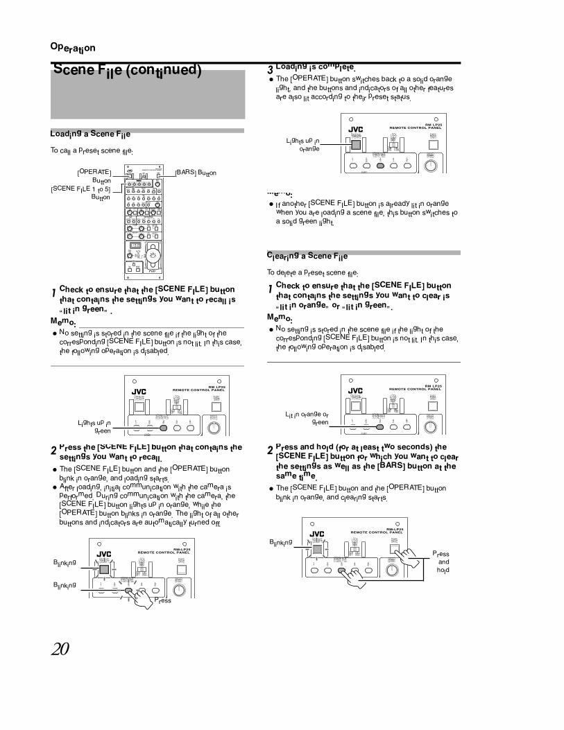
Loading a Scene File
To call a preset scene file:
1 Check to ensure that the [SCENE FILE] button
that contains the settings you want to recall is
�lit in greenB .
Memo: � No setting is stored in the scene file if the light of the
corresponding [SCENE FILE] button is not lit. In this case,
the following operation is disabled.
2 Press the [SCENE FILE] button that contains the
settings you want to recall.
� The [SCENE FILE] button and the [OPERATE] button
blink in orange, and loading starts.
� After loading, initial communication with the camera is
performed. During communication with the camera, the
[SCENE FILE] button lights up in orange, while the
[OPERATE] button blinks in orange. The light of all other
buttons and indicators are automatically turned off.
3 Loading is complete.
� The [OPERATE] button switches back to a solid orange
light, and the buttons and indicators of all other features
are also lit according to their preset status.
Memo: � If another [SCENE FILE] button is already lit in orange
when you are loading a scene file, this button switches to
a solid green light.
Clearing a Scene File
To delete a preset scene file:
1 Check to ensure that the [SCENE FILE] button
that contains the settings you want to clear is
�lit in orangeB or �lit in greenB.
Memo: � No setting is stored in the scene file if the light of the
corresponding [SCENE FILE] button is not lit. In this case,
the following operation is disabled.
2 Press and hold (for at least two seconds) the
[SCENE FILE] button for which you want to clear
the settings as well as the [BARS] button at the
same time.
� The [SCENE FILE] button and the [OPERATE] button
blink in orange, and clearing starts.
Scene File (continued)
-3dB -6dB ALC LOLUX VARIABLE
LEVEL
LEVEL LEVELGAMMA DETAIL KNEE POINT AUTOKNEE
BLACK
COMPRESS STRETCH
WHITE BALANCE MODE
WHITE PAINTR
RBLACK PAINT
B
B
PAINT
PAINT
AUTO WHITE
AUTO BLACK
AUTO
OVER OPEN
UNDER CLOSE
MASTERBLACK
TALLY
CALL PREVIEW
OPERATE BARSLOCKPART
OFF FULL
SCENE FILE SPEED
VARIABLE
PARTSHUTTER
NORMAL1/1001/120 1/250 1/500 1/1000 1/2000
GAIN18dB0dB 3dB 6dB 9dB 12dB 15dB
MANUAL PRESET FAW AW A AW B
PART
PRESET
LEVELIRIS MODE
FULL
PRE
SET
FULL
[OPERATE]
Button
[SCENE FILE 1 to 5]
Button
[BARS] Button
1
OPERATE BARSLOCK
SCENE FILE
2 3 54
SPEED
PART
PART
OFF FULL
Lights up in
green
1
OPERATE BARSLOCK
SCENE FILE
2 3 54
SPEED
PART
OFF FULL
Press
Blinking
Blinking
1
OPERATE BARSLOCK
SCENE FILE
2 3 54
SPEED
PART
PART
OFF FULL
Lights up in
orange
1
OPERATE BARSLOCK
SCENE FILE
2 3 54
SPEED
PART
PART
OFF FULL
Lit in orange or
green
1
OPERATE BARSLOCK
SCENE FILE
2 3 54
SPEED
PART
OFF FULL
Press
and
hold
Blinking
21
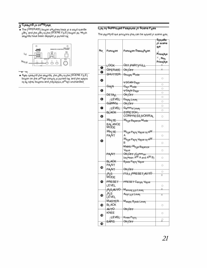
3 Clearing is complete.
� The [OPERATE] button switches back to a solid orange
light, and the light of the [SCENE FILE] button for which
settings have been deleted is turned off.
Memo: � After clearing the settings, the light of the [SCENE FILE]
button on the remote control is turned off, and the status
of all other buttons and indicators remain unchanged.
List of Supported Features in Scene Files
The following are functions that can be stored in scene files.
1
OPERATE BARSLOCK
SCENE FILE
2 3 54
SPEED
PART
PART
OFF FULL
Lit
Not lit
No. Function Function Description
Storage
in scene
file
X:
Possible
�: Not
possible
A LOCK OFF/PART/FULL �
B OPERATE ON/OFF �
D
SHUTTER Shutter ModeX
V.SCAN Data X
EGAIN Gain Mode X
V.GAIN Data X
FDETAIL ON/OFF X
LEVEL Detail Level X
GGAMMA ON/OFF X
LEVEL Gamma Level X
HBLACK STRETCH/
COMPRESS/NORMALX
I
WHITE
BALANCE MODE
White Balance Mode
X
WHITE
PAINT
White Paint Value of AW
AX
White Paint Value of AW
BX
MANU White Balance
ValueX
PAINT ON/OFF (Common
between AW A and AW B)X
J
BLACK
PAINT
Black Paint ValueX
PAINT ON/OFF X
K
IRIS
MODE
FULL/PRESET/AUTO�
PRESET
LEVEL
PRESET Center ValueX
M
IRIS/AUTO
IRIS LEVEL
Manual Iris Level �
Auto Iris Level�
NMASTER
BLACK
Master Black LevelX
R
AUTO
KNEE
ON/OFFX
LEVEL Knee Point X
S BARS ON/OFF �

22
Operation
The brightness of the indicator light on the control panel can
be adjusted in five levels.
1 Set the [LOCK] switch to �OFFB.
2 Press and hold the [BARS] button, and operate
the [IRIS/AUTO IRIS LEVEL] lever at the same
time.
� Doing so switches to the brightness adjustment mode,
and the brightness of the indicator light changes.
Note:
� Normal operation is disabled when in the brightness
adjustment mode. However, the [OPERATE] button
remains enabled.
3 Determine the brightness level.
� Releasing the [BARS] button upon selecting a
random brightness level restores the normal mode,
and the corresponding brightness level is stored.
The tally circuit comes with two input systems, namely
contact input and open collector input.
This is set to contact input in the factory settings. You can
change this to open collector input via settings of the DIP
switch at the side of the main unit.
Remove the cover at the side of this product, and set the tally
circuit supply system using DIP switch no. 6. (A 24 page)
Adjustment of Indicator's Brightness
Indicators for which brightness cannot be adjusted:
� [CALL] button
� [PREVIEW] button
� [TALLY] indicator
1
OPERATE BARSLOCK
SCENE FILE
2 3 54
SPEED
VARIABLE
PARTSHUTTER
NORMAL1/1001/120 1/250 1/500 1/1000 1/2000
PART
OFF FULL
�OFFB
-3dB -6dB ALC LOLUXLEVEL
LEVEL LEVELGAMMA DETAIL KNEE POINT AUTOKNEE
BLACK
COMPRESS STRETCH
WHITE BALANCE MODE
WHITE PAINTR
RBLACK PAINT
B
B
PAINT
PAINT
AUTO WHITE
AUTO BLACK
AUTO
OVER OPEN
UNDER CLOSE
MASTERBLACK
TALLY
CALL PREVIEW
1
OPERATE BARSLOCK
SCENE FILE
2 3 54
SPEED
VARIABLE
PARTSHUTTER
NORMAL1/1001/120 1/250 1/500 1/1000 1/2000
GAIN18dB0dB 3dB 6dB 9dB 12dB 15dB
MANUAL PRESET FAW AW A AW B
PART
PRESET
LEVELIRIS MODE
FULL
PRE
SET
FULL
VARIABLE
PART
OFF FULL Press and
hold
Lever
Operation
Self-illuminating
button that
enables
brightness
adjustment
Input/Output of Rear Ports

23
Tally Input Terminal
� Input Conditions
� No-voltage relay contact a input, or open collector input
(contact a: �OpenB at normal times, and �ClosedB during
Tally)
� 10 kK for internal, connected to 5 V power
� Input signals can be set using the DIP switch ( A 24 page �DIP Switch 6B)
PREVIEW Output Terminal
� Output Conditions
� Equivalent to open collector output
� External connection capacity DC 5 V, 10 mA
� Polarity: “HIGH” when normal and “LOW” during
PREVIEW
VCC
GNDGND
R
DC 5 V
5 V
OUT
TALLY IN
�PGM,PVM)
GND
OUT
Tally Input Terminal
RM-LP25U Switcher
Example (1)
Switcher
Example (2)
Relay, Switch, etc.
Tally Input Equivalent
Circuit
OUT
GND
OUT
INR
DC 5 V
GNDGND
R
DC 5 V
PREVIEW Output
Terminal
Switcher Example (1)
Switcher Example (2)
Buzzer, Lamp,
Indicator, etc.

24
Operation
You can partially switch the settings of features (factory settings).
All switches are set to �OFFB in the factory settings.
Note:
� Be sure to change the DIP switch settings under Operate
OFF mode.
� DIP Switch 1
For setting the [GAIN] selection button's �ALCB feature.
Note:
� For GY-HD200 and GY-HD250, this setting is invalid as
the gain value and shutter are standard settings when
automatically set (ALC+EEI). To use GY-HD200 and GY-
HD250 when only the gain value is automatically set
(ALC), please consult your nearest JVC's authorized
dealers.
� DIP Switch 2
For setting the [AUTO IRIS LEVEL] feature.
� DIP Switch 3
For setting the [IRIS MODE] when �ALCB is selected for the
[GAIN] button.
� DIP Switch 4
Reserved switch. Make sure that this is set to �OFFB during
use.
� DIP Switch 5
Reserved switch. Make sure that this is set to �OFFB during
use.
� DIP Switch 6
For setting input signals of the [TALLY] terminal.
Setting Selection DIP Switch
Fun-
ction
For selecting the feature to use when �ALCB is
selected, if the connected camera comes with both
the (ALC) mode, which automatically adjusts the
gain value only, as well as the (ALC+EEI) mode,
which adjusts both the gain and shutter values
automatically.
Set-
ting
OFF Use as �ALCB.
ON Use as �ALC+EEIB.
Fun-
ction
For specifying whether the �IRISB lever is to be
used as the [AUTO IRIS LEVEL] adjustment lever
when the iris mode is set to �AUTOB.
Set-
ting
OFF Use as adjustment lever for
�AUTO IRIS LEVELB.
ON Use as adjustment lever for
�AUTO IRIS LEVELB disabled.
(Operation is disabled, and the
AUTO IRIS LEVEL is fixed to the
standard value.) )
Fun-
ction
For setting whether the iris mode is to be forcibly
switched to �AUTOB when �ALCB is selected for the
[GAIN] button.
Set-
ting
OFF Forcibly set to �AUTOB.
ON Not forcibly set to �AUTOB. (Iris
mode complies with the switch
status.) )
Fun-
ction
For setting the input signals of the [TALLY] terminal.
Set-
ting
OFF Use as �contact input systemB.
ON Use as �open collector input
systemB.
HIGH: ON, LOW: OFF

25
Features that can be controlled using this product vary
according to the camera connected.
Features that are enabled/disabled when GY-HD250/GY-
HD251/GY-HD200/GY-HD201 are connected are shown
below.
T The above feature may not function depending on the
version of the camera's software. For details, please
consult JVC's authorized dealers.
Operable Features
No. Function
GY-HD250
GY-HD251
GY-HD200
GY-HD201
X: Enabled, �: Disabled
D
SHUTTER NORMAL X X
1/100�1/120
X X
1/250 X X
1/500 X X
1/1000 X X
1/2000 X X
VARIABLE� �
SPEED
E
GAIN -6dB � �
-3dB � �
0dB X X
3dB X X
6dB X X
9dB X X
12dB X X
15dB X X
LEVEL LEVELGAMMA DETAIL KNEE POINT AUTOKNEE
BLACK
COMPRESS STRETCH
WHR
AUTO
UNDER
TALLY
CALL PREVIEW
1
OPERATE BARSLOCKPART
OFF FULL
SCENE FILE
2 3 54
FULL
B
E
G
C
H
O
R
S
�
P
Q
F
WHR
AUTO
UNDER
N
D
I
J
L
M
K
U VT
No. Function
GY-HD250
GY-HD251
GY-HD200
GY-HD201
X: Enabled, �: Disabled
E
GAIN 18dB X X
ALC X X
LOLUX � �
VARIABLE� �
LEVEL
FDETAIL X X
LEVEL X X
GGAMMA XT XT
LEVEL XT XT
H
BLACK NORMAL X X
STRETCH X X
COMPRESS X X
I
WHITE
BALANCE MODE
MANUAL X X
PRESET X X
FAW X X
AW A X X
AW B X X
WHITE PAINT X X
AUTO WHITE X X
JAUTO BLACK � �
BLACK PAINT XT XT
KIRIS Iris Control
Unit
X X
LIris F Value
Display
XT XT
M LEVEL X X
N MASTER BLACK X X
O TALLY XT �
P CALL XT �
Q PREVIEW X X
RAUTO KNEE X X
KNEE POINT X X
S BARS X X
VTALLY(PGM) X X
TALLY(PVW) X X

26
Operation
When RM-LP25U is connected to a camera, all features that
are available on RM-LP25U can only be controlled via RM-
LP25U, and control of these features using the camera is
disabled.
Switches on the camera that are disabled, as well as
disabled menu items are as follows.
� Switches that are disabled
� GAIN
� SHUTTERT� WHT.BAL
� FULL AUTOT� User 1, 2 and 3 with the following features assigned
BARS B.STRETCH1-5 B.COMPRESS1-5 AE LEVEL+ AE LEVEL-
Memo: � SHUTTER will also be disabled if the setting is
�VARIABLEB or below �1/30B.
� FULL AUTO is forcibly set to �OFFB regardless of the
switch status.
� Menu items that are disabled
Memo: � CINEMA is forcibly set to �OFFB. To adjust MATRIX, make
use of the menu on the camera.
� GAMMA is fixed to the menu setting value of camera
before connecting remote control. However, it is forced to �STANDARDB if the menu setting
value of camera before connecting remote control is
�OFFB.
� Remote Cable
Manufactured by Hosiden Corporation (Length: 5 m)
Operation of Connected Camera
Menu Display
Menu Page FunctionGY-HD250
GY-HD251
GY-HD200
GY-HD201
CAMERA
OPERATION
AE LEVEL REMOTE REMOTE
BARS REMOTE REMOTE
CAMERA
PROCESS[1/2]
MASTER
BLACKREMOTE REMOTE
DETAIL REMOTE REMOTE
CAMERA
PROCESS[2/2]
BLACK REMOTE REMOTE
KNEE REMOTE REMOTE
LEVEL REMOTE REMOTE
ADVANCED
PROCESS
CINEMA [OFF]T [OFF]T
GAMMA [STANDARD]T [STANDARD]T
[CINEMA]T [CINEMA]T
[FILMOUT]T [FILMOUT]T
LEVEL REMOTE REMOTE
WHITE
BALANCE
WHITE
PAINT RREMOTE REMOTE
WHITE
PAINT BREMOTE REMOTE
Remote Connector Specifications
Pin
No.Signal Description Level IN/OUT
1 GND GND ^ ^
2 RM/CTL Operate Control +5V OUT
3 GND GND ^ ^
4 SID2 Received Data +5V IN
5 SID1 Transmitted Data +5V OUT
6 +9V Vcc +9V IN
5 6
3 4
2�

27
Others
i
� Cameras that can be connected
: GY-HD250 Series
: GY-HD200 Series
� Power Supply
: +9 V ± 0.5 V
� Power Consumption:
: Approx. 2 W and below
� Ambient Temperature
: -5I to 40I
� Allowable Operating Humidity
: 30% RH to 80% RH
� Mass
: 2.4 kg
� Cable Length
: 5 m
� Installation Angle
: Within ±45�
� Attachments
Instruction Manual................................. 1
Warranty................................................ 1
Clamp Filter (A 14 page) ..................... 1
� Dimensional Outline Drawing (Unit: mm)
T The specifications and appearance of this product and
other related products may be modified for improvement
without prior notice.
Troubleshooting
Troubleshooting Check Point Reference Page
Power does not turn ON/OFF
upon pressing the Operate
button.
� Is the Operation Lock switch set to �PARTB or �FULLB? Set
to �OFFB.
A 7 page
� Are the cables properly connected? A 14 page
� Is the power of the connected camera functioning normally?
Unable to select �-3dBB or �-
6dBB of the gain selection
button when they are pressed.
� Is the �-3dBB or �-6dBB button lit in green? Features
(Options) that are not available at the camera's end are not
lit and are disabled.
A 16 page
Function cannot be turned ON
(orange light on) after pressing
the white paint button.
� Is the white balance selection set to �PRESETB or �FAWB?
Select �AW AB or �AW BB.
A 9 page
Function cannot be turned
OFF (green light on) after
pressing the white paint
button.
� Is the white balance selection set to �MANUALB? When
�MANUALB is selected, the WHITE PAINT R/B knob is
enabled at all times, and therefore the white paint button
remains ON (orange light on).
A 9 page
Lamp light is dull. � The lamp brightness of this product can be adjusted. A 22 page
The lens iris of the camera
does not move even when the
iris lever is moved.
� Is the lens iris mode set to “MANUAL”? Set it to “AUTO” or
“A”.
A 14 page
Specifications
10 85
105
7862�510
3dB 6dB ALC LOLUX VARIABLE
LEVEL
LEVEL LEVELGAMMA DETAIL KNEE POINT AUTOKNEE
BLACK
COMPRESS STRETCH
WHITE BALANCE MODE
WHITE PAINTR
R
BLACK PAINT
B
B
PAINT
PAINT
AUTO WHITE
AUTO BLACK
AUTO
OVER OPEN
UNDER CLOSE
MASTERBLACK
TALLY
CALL PREVIEW
VARIABLE
1
OPERATE BARSLOCK
SCENE FILE
2 3 54
SPEED
PARTSHUTTER
NORMAL1/1001/120 1/250 1/500 1/1000 1/2000
GAIN
18dB0dB 3dB 6dB 9dB 12dB 15dB
MANUAL PRESET FAW AW A AW B
PART
PRESET
LEVELIRIS MODE
FULL
PRE
SET
FULL
PART
OFF FULL

© 2007 Victor Company of Japan, LimitedLST0594-001A
RM-LP25U
REMOTE CONTROL PANEL
![Flat Panel Indoor Antenna - Winpluswinplus.com.au/links/UR39677 Bauhn Universal Remote Manual.pdf · Flat Panel Indoor Antenna Universal Remote Control ... [CODE SETUP]. Then release](https://img.pdfslide.us/doc/110x75/5aff134f7f8b9a864d8fe22a/flat-panel-indoor-antenna-bauhn-universal-remote-manualpdfflat-panel-indoor-antenna.jpg)


![Live-View Remote RM-LVR3 · Live-View Remote RM-LVR3 Read This First Identifying the parts [1] Screen display during single connection [2] Screen display during multi connection [3]](https://img.pdfslide.us/doc/110x75/5eadff3784c9a55408434b68/live-view-remote-rm-lvr3-live-view-remote-rm-lvr3-read-this-first-identifying-the.jpg)