Embed Size (px)
Citation preview

REMOTE CONTROL LED DIMMER USING
NRF24L01+ RADIO AND MICROCONTROLLERS
A Design Project Report
Presented to the School of Electrical and Computer
Engineering of Cornell University
in Partial Fulfillment of the Requirements for the Degree of
Master of Engineering, Electrical and Computer Engineering
Submitted by
Xiaobin Li
MEng Field Advisor: Bruce Land
Degree Date: May 2017

Abstract
Master of Engineering Program
School of Electrical and Computer Engineering
Cornell University
Design Project Report
Project Title: Remote Control Led Dimmer Using NRF24L01
radio and PIC32 Microcontroller
Author: Xiaobin Li
Abstract:
The object of this project is to implement a remote control led dimmer using
nrf24L01 radios and microcontrollers. There are four button as inputs: on, off,
brighter and dimmer which make the led behave accordingly. The design involves
button detection, RF remote communication and led circuit design. There are two
radios communicating with each other through 2.5GHz frequency signal with
data, address and pipe. The microcontroller are used for detecting incoming
button press and generating PWM signal to control the light intensity of the led.
The remote control dimmer will not only be a convenient product for people’s
daily life but also an energy-efficient product that could save energy for users.
Keyword: microcontroller, remote control, led

Executive Summary
Lamps are necessary products for everyone’s home. Billions of lamps consumes
mass of energy every day. Sometimes, the lamp is kind of far away from where
we are and it is not convenient to walk towards the lamp and then come back.
Therefore, it is useful to have a remote control led dimmer which can help save
energy and make human’s daily life more convenient as well.
Based on the requirements above, a remote control led dimmer is built in this
project using nrf24L01+ radio modules and microcontrollers. The control panel
includes four buttons for people to choose to turn on, off the led or make it
brighter or dimmer. There are two parts for the design: transmitter part and
receiver part. Transmitter part includes button detection and message
transmitting. Receiver part includes message receiving, pulse width modulation
and led circuit. Button signal will go through the whole chain from transmitter
part to receiver part to finally control five led light intensities.
Various tests are designed to test the function and performance of the project.
There are five light intensities to clearly tell the difference when pressing the
buttons. The range of radio communication is over 20 meters after testing it on
two sides of the lab. The remote control can also work on different channels such
as 2.4GHz and 2.5GHz.

Executive Summary ............................................................................................... 3
1. Introduction ...................................................................................................... 5
1.1 Motivation ................................................................................................. 5
1.2 Background ................................................................................................ 5
2. Circuit Design .................................................................................................... 6
2.1 Main issues ................................................................................................ 6
2.2 Button Detection ....................................................................................... 7
2.3 NRF24L01 Radio Module ............................................................................ 8
2.3.1 Hardware Connection ....................................................................... 8
2.3.2 Software Setup ................................................................................. 9
2.3.3 Frequency ......................................................................................... 9
2.3.4 Addresses and Pipes ......................................................................... 9
2.3.5 Transmitting and Receiving ............................................................. 10
2.4 LED Control .............................................................................................. 11
2.4.1 Pulse Width Modulation ................................................................. 11
2.4.2 LED circuit ....................................................................................... 11
3. Result ............................................................................................................... 12
4. Conclusion and Future Work ........................................................................... 13
5. Acknowledgement .......................................................................................... 13
6. Reference ........................................................................................................ 14
7. Appendix ......................................................................................................... 15
7.1 Code......................................................................................................... 15
7.2 Schematic ................................................................................................ 23

1. Introduction
1.1 Motivation
Remote control is handy and convenience. With the development of embedded
system and remote control, lots of electronic equipment becomes wireless and
remote control. Imaging you sitting in the sofa, remote-controller in your hand,
you can easily switch TV channel or volume from a certain distance. Also think
about mouse for personal computer or laptop, more and more people are using
wireless mouse without the bother of mouse cable. Now think about a lamp, if we
have a remote controller to control a lamp, we can turn it on easily from a
distance. A scenario could be coming back home late at night and we turn the
lamp on before we entered the house. Also, we can easily turn it off when we
want to sleep without getting up to the lamp.
Energy saving is also an important part to mention nowadays. The appearance of
mass of electronic devices consumes more and more energy. I am thinking that it
would be better if we can dim the light of the remote-control lamp to save
energy. With a remote-control dimmer, we can change the light of the bulb
according to different conditions.
1.2 Background
There are many ways to do wireless and remote control, such as infrared
radiation (IR), radio frequency (RF). Infrared radiation is invisible light with a
wavelength between 700nm to 1mm. Remote control for television sets are
mainly realized by infrared radiation. However, infrared radiation cannot go
through walls or other obstacles. Therefore it is not suitable for our projects since
there might be some obstacle between our controller and the lamp. Radio
frequency is electromagnetic waves with a frequency range from 3 kHz to 300
GHz. RF is widely used for wireless communication in our daily life, such as WIFI,
wireless mouse and wireless keyboard. The waves can go through walls to travel a
certain distance with low power which is good enough for our home application.

There are many choices of the light bulb also. Incandescent bulb is classic choice
and can be used with a dimmer switch. However, it cost too much energy and all
standard incandescent bulbs are out of the market and will no longer be
produced. Compact fluorescent (CFL) bulbs is a better option with lower energy
cost and reliable quality. CFL bulbs is lighted up by the contact of UV light
generated by each end of the tube and phosphor coating on the inside of the
bulb. However, it is kind of difficult to make it work with a dimmer. Light emitting
diode (LED) are energy-efficient and commonly used in our daily life nowadays.
LED bulbs are illuminated by an electrical current pass through semiconductor
material. There are 3W or 5W LED which are good enough for our project. The
only problem might be the heat. Led will produce mass of heat when it is on,
which requires a heat sink to absorb heat and keep the bulb away from damage.
In 2017, new US regulation makes it difficult for CFLs to qualify for an ENERGY
STAR® rating and many companies decide to drop CFLs and only produce LED
bulbs. The bulb for this project should be bright enough to see different level of
light and energy-efficient, therefore, a 5W LED bulb will be our final choice.
2. Circuit Design
2.1 Main issues
Based on the discussion above and the requirements, the following figure 1 shows
the overview diagram for this project. There are two parts: transmitter part and
receiver part. For transmitter part, four buttons are original input source
triggered by users. Input signal is received by PIC32 pins and then PIC32 sends
message to the transmitter. For receiver part, the radio receives the message and
sends it to PIC32. PIC32 will send out corresponding control signal to led circuit.
There are three main issues to be solved: button detection, radio communication
and LED control circuit.

Figure1 Overview Design Diagram
2.2 Button Detection
The button detection scheme is shown in Appendix. A0 and A3 are digital output
pins from PIC32 while B7 and B13 are digital in pins from PIC32. There are two
kinds of resistors: 300 ohms and 10k ohms. 300 ohms resistors are to avoid short
circuit when two buttons are pushed together. 10k ohms resistors are to avoid
open circuit input when no button pushed.
Figure2 Snippet of Button Detection
Figure2 is a snippet of button detection that explains how the button detection
works: first, set an array called keytable to store all possible button-press cases.
Then constant pattern scan each row and detect if there is an input to each

column. If the answer is yes, concatenate keypad with pattern which should be a
keycode in the keytable.
2.3 NRF24L01 Radio Module
2.3.1 Hardware Connection
The radio module for this project is nrf24L01+. It is a single chip 2.4GHz
transceiver to work with microcontroller. There are 8 pins on it which is shown in
figure and table below.
Figure3 Nrf24L01 Radio Pinout
Credit: Nrf24L01 Radio Library by Douglas and Fred
Table1 One Possible Pin Connection for Radio and MCU
Credit: Nrf24L01 Radio Library by Douglas and Fred

The radio requires an SPI connection, an interrupt pin, and a connection to Vdd
and ground. A list of pins and their connection is shown in table above. Pin 1 and
2 connects to GND and Vcc correspondingly to PIC32. Pin3 is chip enable and pin4
is chip select which are both control signals. They are connected to I/O pins of
PIC32. The radio communicate with PIC32 through SPI and we are using SPI2 and
SCK2 of PIC32. Pin8 is interrupt request port which is connected to external
interrupt1 of PIC32.
2.3.2 Software Setup
nrf_setup function initializes SPI for communicating with the radio, setup the
radio interrupt setup I/O pins, and reset all register values on the radio. It must be
called before calling any other radio functions.
2.3.3 Frequency
The nrf24l01+ radio can work with 126 channels, ranging from 2.4 GHz to 2.525
GHz. According to nrf library, the frequency can be set with nrf_set_rf_ch
function. There is an equation to calculate the frequency, frequency = 2400 + ch
(MHz), where ch is the input to the nrf_set_rf_ch function. Note that the
frequency of the transmitter and receiver must be the same to communicate well.
The following line of code show an example to set the frequency to 2.5 GHz,
which is the frequency we are using for this project.
nrf_set_rf_ch(0x64); // freq = 2400 + 6*16+4 MHz = 2.5GHz
2.3.4 Addresses and Pipes
The nrf24l01+ uses addresses on the receiver and transmitter to identify where
should each packet go. In order to communicate well, the address on transmitter
side and receiver side should be set to the same address. On receiver side, there
are six pipes numbered 0-5 for data to be caught. Each of these pipes has a 3-5
byte address field that determines which packets are received on that pipe. The

length of the address can be set to be 3-5 bytes using the nrf_set_address_width
function. Each pipe can have a different address, allowing them each to receive
data from a different module. The address of a pipe can be set using the
nrf_set_rx_addr. On transmitter side, there is also an address called TX address.
This sets the address which this radio transmits with. In order to send to a pipe on
a receiver that has its address set to 0xFFF, the TX address of the transmitter must
be set to 0xFFF as well. The address of the transmitter be set using the
nrf_set_tx_addr function according to nrf library.
2.3.5 Transmitting and Receiving
The nrf24l01+ can send up to 32 bytes of data in a packet. To send a packet, the
desired number of bytes to send must be specified in the nrf_send_payload
function. This function will automatically handle transmitting. After calling this
function the radio will no longer be in receive mode, so it must be set back to
receive mode using the nrf_state_rx_mode function in order to receive more
packets. Once in this mode the radio will wait to receive packets. If a packet is
received, then nrf_payload_available function will return 1. If no packet is
available, nrf_payload_available will return a 0.
When a payload is available, the nrf_get_pipe function will return what pipe the
data came in on and the nrf_get_payload_width function will return the length of
the received payload. The payload can be read into a buffer using the
nrf_get_payload function.
It is necessary to check nrf_payload_available before calling the nrf_get_payload
function because we do not want trash data. Also after a payload is received, that
payload must be read using nrf_get_payload prior to the next payload being
received. If a new payload arrives without the first payload being read, the first
payload will be lost.
2.4 LED Control
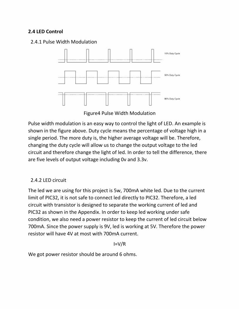
2.4.1 Pulse Width Modulation
Figure4 Pulse Width Modulation
Pulse width modulation is an easy way to control the light of LED. An example is
shown in the figure above. Duty cycle means the percentage of voltage high in a
single period. The more duty is, the higher average voltage will be. Therefore,
changing the duty cycle will allow us to change the output voltage to the led
circuit and therefore change the light of led. In order to tell the difference, there
are five levels of output voltage including 0v and 3.3v.
2.4.2 LED circuit
The led we are using for this project is 5w, 700mA white led. Due to the current
limit of PIC32, it is not safe to connect led directly to PIC32. Therefore, a led
circuit with transistor is designed to separate the working current of led and
PIC32 as shown in the Appendix. In order to keep led working under safe
condition, we also need a power resistor to keep the current of led circuit below
700mA. Since the power supply is 9V, led is working at 5V. Therefore the power
resistor will have 4V at most with 700mA current.
I=V/R
We got power resistor should be around 6 ohms.

3. Result
First, I tested the whole design by pressing the button to see if it got
corresponding response. There are five light intensities set in PWM. Some of the
results are shown in the figure below. The first one on the left top shows the
darkest level, the second one on the right top shows a medium level while the
third one on the bottom shows the brightest level. Pressing button dimmer, the
light intensity will become darker and darker until the darkest level while pressing
the brighter button, the light intensity will become brighter and brighter until the
brightest level. Pressing off button will turn off the light and on button will turn
on the light. Note that the button dimmer and brighter is not available when the
light is off.
Dark Medium
Bright

Then I test the design with different channels and pipes and it works similar to
how it worked before. An interesting result is that when I change the frequency to
around 2.4GHz, it got garbage messages more easily. That because 2.4GHz
frequency overlap with WIFI or other wireless communication like wireless mouse
or keyboard.
At last I tested the range of radio communication to see how far it can work. The
receiver part was placed at one of the end of the lab while the transmitter part
was placed at the other end. The distance should be around 15 meters and the
remote control works out fine even with some obstacles such as electronic
equipment and desks between transmitter and receiver.
Overall, the design functions well in an environment like home with a
communication range more than 15 meters.
4. Conclusion and Future Work
The basic function of remote control LED dimmer has completed and functioned
well. To make it more handy and convenient, we may want to add voice control
instead of pressing buttons. In that case, we can just say easy commands such as
on, off, up, down and do not bother to press buttons to control the light.
5. Acknowledgement
I would like to express my greatest appreciation to Dr. Bruce Land for accepting
me as one of his M.Eng project students and his guidance all through the
semester. He is always there in the lab, willing to help. His patience and
experience helped me solve problems quickly and efficiently. He also provided
various devices for testing and what I need for this project. I also want to thank
Fred for his valuable advice on setting up the radio.

6. Reference
[1] nrf24l01 Library for PIC32MX250F128B, Douglas Katz and Fred Kummer, May
2016, ece4999 Independent Study, Cornell University
[2] nRF24L01+ Single Chip 2.4GHz Transceiver Product Specification v1.0, Nordic
Semiconductor, September 2008

7. Appendix
7.1 Code
Transmitter side
// graphics libraries
#include "config.h"
// serial stuff
#include <stdio.h>
#include <stdlib.h>
// threading library
#define SYS_FREQ 40000000 // 40 MHz change the frequency of the clock
// radio library
#include "nrf24l01.h"
#include "pt_cornell_TFT.h"
/*
* This code is for transmitter side. PIC32 detected button press and send signal to the radio.
* After radio receive the siganl, it will then send corresponding message to the receiver side.
*/
// set up the radio
void radioSetup() {
nrf_setup(); // initializing function
nrf_set_rf_ch(0x64); // freq = 2.5 GHz 2400+ch(MHz)
nrf_set_arc(0x07); // 7 restransmits (0-15 times)
nrf_set_ard(0x00); // 250 us between retransmission 250+x*250 us
nrf_en_aa(0); // enable autoack on pipe0
nrf_set_pw(1,0); // set the payload width to be 1 byte (1-32 bytes, 0-5 pipe)

nrf_set_address_width(3); // set the address width 5 bytes(3-5)
// tx address and the pipe 0 rx address must be the same for autoack mode
nrf_set_rx_addr(0, 0xAABBCC, 3); // set pipe 0, receiver address to be 3 bytes
nrf_set_tx_addr(0xAABBCC); // set tx address
}
void main(void) {
INTEnableSystemMultiVectoredInt();
radioSetup(); // setup the radio for this program
mINT1ClearIntFlag();
// === Keypad Thread =============================================
// connections:
// A0 -- row 1 -- thru 300 ohm resistor -- avoid short when two buttons pushed
// A3 -- row 2 -- thru 300 ohm resistor
// B7 -- col 1 -- 10k pulldown resistor -- avoid open circuit input when no button pushed
// B13 -- col 2 -- 10k pulldown resistor
// 0x01 for row 1 ; 0x08 for row 2;
// 0x80 for col 1 ; 0x2000 for col 2
// left-top row1col1 0x81; right-top row2col1 0x88;
// left-bottom row1col2 0x2001; right-bottom row2col2 0x2008;
int keypad, i, pattern;
int keytable[4]={0x81, 0x88, 0x2008, 0x2001};
// init the keypad pins A0,A3 and B7,B13
// PortA ports as digital outputs
mPORTASetPinsDigitalOut(BIT_0 | BIT_3); //Set port as output
// PortB as inputs

mPORTBSetPinsDigitalIn(BIT_7 | BIT_13);
char message[4] = {0,1,2,3}; // Byte to be transmitted
while(1)
{
// read each row sequentially
mPORTAClearBits(BIT_0 | BIT_3);
pattern = 1;
mPORTASetBits(pattern);
for (i=0; i<4; i++) {
keypad = mPORTBReadBits(BIT_7 | BIT_13);
if(keypad!=0) {keypad |= pattern ; break;}
mPORTAClearBits(pattern);
pattern <<= 1;
mPORTASetBits(pattern);
}
// search for keycode
if (keypad > 0){ // then button is pushed
if (keypad == 0x81) { // 0
while(!nrf_send_payload(&message[0],1));
}
else if( keypad == 0x88 ){ // 1
while(!nrf_send_payload(&message[1],1));
}

else if( keypad == 0x2008 ){ // 2
while(!nrf_send_payload(&message[2],1));
}
else if( keypad == 0x2001 ){ // 3
while(!nrf_send_payload(&message[3],1));
}
}
else i = -1; // no button pushed
nrf_delay_ms(300); // button debounce time buffer
}
} // main
Receiver side
#include "config.h"
#include "tft_gfx.h"
#include "tft_master.h"
#include <stdio.h>
#define SYS_FREQ 40000000
#include "nrf24l01.h"
// These two defines are for the tft
#define spi_channel 1
#define spi_divider 10

/* This code control the receiver and led circuit.
* The radio catch the message from transmitter and send it to PIC32.
* PIC32 analyzes the data and generates PWM control siganl for led circuit.
*/
// set up the radio
void radioSetup() {
nrf_setup(); // initializing function
nrf_set_rf_ch(0x64); // freq = 2.410 GHz 2400+ch(MHz)
nrf_en_aa(0); // enable autoack on pipe0
nrf_set_pw(1,0); // set the payload width to be 1 byte (1-32 bytes, 0-5 pipe)
nrf_set_address_width(3); // set the address width 5 bytes(3-5)
// tx address and the pipe 0 rx address must be the same for autoack mode
nrf_set_rx_addr(0, 0xAABBCC, 3); // set pipe 0, receiver address to be 5 bytes
}
void main(void) {
INTEnableSystemMultiVectoredInt();
radioSetup(); // setup the radio for this program
OpenTimer3(T3_ON | T3_PS_1_1, 40000);
mINT1ClearIntFlag();
// light level: 0-off(ct=0); 2-dim(ct=1500); 3-mid(ct=3000); 4-on(ct=40001))
// OpenOC1(OC_ON | OC_TIMER3_SRC | OC_PWM_FAULT_PIN_DISABLE , light_level, 20000 ); //
// OC1 is PPS group 4, map to RPA0 (pin 2)
PPSOutput(1, RPA0, OC1);

tft_init_hw(); // setup for tft
tft_begin(); // setup for tft
tft_fillScreen(ILI9340_BLACK);
//240x320 vertical display
tft_setRotation(0); // Use tft_setRotation(1) for 320x240
char buffer[120]; // a buffer for writing to the tft
// arrays to read payloads into
char rx_message;
int width=1; // the width of the received payload
tft_setTextColor(ILI9340_GREEN);
tft_setTextSize(2);
tft_setCursor(0, 0);
sprintf(buffer, "%s", "Waiting for data...");
tft_writeString(buffer);
int led_level=0;
int i=0; // # of the received messages for TFT
while (1) {
// enter receive mode to search for packets
nrf_state_rx_mode();
if(nrf_payload_available()){ // wait for a payload to be received
//nrf_delay_ms(10);
nrf_get_payload(&rx_message, 1); // read the payload into the array
if(rx_message == 0){
OpenOC1(OC_ON | OC_TIMER3_SRC | OC_PWM_FAULT_PIN_DISABLE , 0, 20000 );
led_level = 0;
}
else if(rx_message == 3){
OpenOC1(OC_ON | OC_TIMER3_SRC | OC_PWM_FAULT_PIN_DISABLE , 40001, 20000 );
led_level = 40001;
}
if( (led_level>0) & (led_level<=40001) ){
if(rx_message == 1){
led_level = led_level + 8000;
if(led_level>40001)
{
led_level = 40000;
}
OpenOC1(OC_ON | OC_TIMER3_SRC | OC_PWM_FAULT_PIN_DISABLE , led_level, 20000 );
}
else if(rx_message == 2){
led_level = led_level - 8000;
if(led_level<8000)
{
led_level = 8000;
}

OpenOC1(OC_ON | OC_TIMER3_SRC | OC_PWM_FAULT_PIN_DISABLE , led_level, 20000 );
}
}
// display the received data on the tft
tft_setTextColor(ILI9340_BLUE);
tft_setTextSize(2);
tft_setCursor(0, 20);
sprintf(buffer, "%s", "Received data:");
tft_writeString(buffer);
tft_setCursor(40, 60);
tft_setTextColor(ILI9340_RED);
sprintf(buffer, "%s", "Width:");
tft_writeString(buffer);
tft_setCursor(110, 60);
sprintf(buffer, "%d", width);
tft_writeString(buffer);
tft_setTextColor(ILI9340_BLUE);
tft_setCursor(0, 40+20*i);
sprintf(buffer,"%d", rx_message);
tft_writeString(buffer);
i=i+1;
nrf_delay_ms(500);
}
}
} // main

7.2 Schematic
Schematic for Transmitter Part

Schematic for Receiver Part