Embed Size (px)
Citation preview
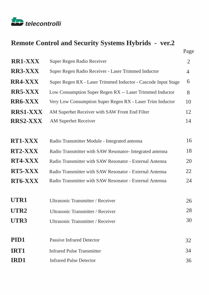
telecontrolli
RR1-XXX
Remote Control and Security Systems Hybrids - ver.2
RR3-XXX
RR4-XXX
RR5-XXX
RR6-XXX
Page
2
4
6
8
10
Super Regen Radio Receiver - Laser Trimmed Inductor
Super Regen Radio Receiver
Super Regen RX - Laser Trimmed Inductor - Cascode Input Stage
Low Consumption Super Regen RX -- Laser Trimmed Inductor
Very Low Consumption Super Regen RX - Laser Trim Inductor
RRS1-XXX AM Superhet Receiver with SAW Front End Filter
AM Superhet Receiver
12
14RRS2-XXX
Radio Transmitter Module - Integrated antennaRT1-XXX
Radio Transmitter with SAW Resonator- Integrated antennaRT2-XXX
Radio Transmitter with SAW Resonator - External AntennaRT4-XXX
Radio Transmitter with SAW Resonator - External AntennaRT5-XXX
Ultrasonic Transmitter / ReceiverUTR1
Ultrasonic Transmitter / ReceiverUTR2
Ultrasonic Transmitter / ReceiverUTR3
Passive Infrared DetectorPID1
16
18
20
22
24
26
28
30
RT6-XXX Radio Transmitter with SAW Resonator - External Antenna
IRT1
IRD1
Infrared Pulse Transmitter
Infrared Pulse Detector
32
34
36
Fixed Frequency Super Regenerative RadioReceiver
telecontrolli RR1-XXX
The RR1-XXX is a super regenerative data receiver.
Sensitivity typically exceedes -100dBm (2.2uVrms)when matched to 50 ohm.
The tuning frequency can be custom-specified in therange 200 to 450 MHz.
It shows stable electrical characteristics thanks to"Thick film hybrid" technology.
General description
Applications
In
BLOCK DIAGRAM
XXX: custom-specified working frequency(200 ÷ 450 MHz)
Standard European and U.S. frequencies (315MHz,418MHz, 433.92MHz) are readly available fromstock.
••••
Home security systemsCar Alarm systemsRemote gate controlsSensor reporting
Radio Receiver
LPFilter
QuenchOscillator
ComparatorOUT
GNDRF AF
PointAF
VRF VAF
GNDTest
GND
Pre-Amp OscillatorRF RF AM
Ampli

1 2 7 10 15
telecontrolli
CHARACTERISTICS MIN TYP MAX UNIT
Electrical Characteristics
VRF
VAF
Vol
Voh
IS
TYPICAL APPLICATION
Mechanical DimensionsPin Description
1 RF +V 9 NC2 RF GND 10 AF +V3 IN 11 AF GND4 NC 12 AF +V5 NC 13 Test Point6 NC 14 OUT7 RF GND 15 AF +V8 NC
CC
CC
CC
CC
HEAD OFFICE & PLANT SALE OFFICE
RF Supply Voltage
AF Supply Voltage
Supply Current
FW
BW
TOP
Working Frequency
Tuning Tolerance
-3dB Bandwidth
RF Sensitivity (100% AM)
Level of Emitted Spectrum
Low-Level Output Voltage
High-Level Output Voltage
Max Data Rate
Operating Temperature Range
4.5
4.5
200 450
3.6
0.6
-65 -60
5.5
5.5
5
5
3.5
VDC
VDC
V
V
2.5
±0.5
±2 ±3
2
-100 -105
mA
dBm
dBm
MHz
MHz
MHz
KHz
-25 +80 °C
DECODERIN OUT
+5V
AERIAL
38.1mm
12.7mm
2.54mm
1 2 7 10 15
Components Side
1mm
RR1-XXX
Ta = 25°C unless otherwise specified
Via Naz. delle Puglie, 17780026 CASORIA (NA), ItalyTel: +39 81 7599033Fax: +39 81 7596494
Via Ludovico Mancini, 120129 MILANO, ItalyTel: +39 2 5516417Fax: +39 2 55180212
Super Regenerative Radio Receiver With LaserTrimmed Inductor
telecontrolli RR3-XXX
The RR3-XXX is a super regenerative data receiver.
Sensitivity typically exceedes -100dBm (2.2uVrms)when matched to 50 ohm.
It shows high frequency stability also in presence ofmechanical vibrations, manual handling and in a widerange of temperature.
The frequency accuracy is very high thanks to lasertrimming process. PATENTED.
General description
Applications
In
BLOCK DIAGRAM
XXX: custom-specified working frequency(200 ÷ 450 MHz)
Standard European and U.S. frequencies (315MHz,418MHz, 433.92MHz) are readly available fromstock.
••••
Home security systemsCar Alarm systemsRemote gate controlsSensor reporting
Radio Receiver
LPFilter
QuenchOscillator
ComparatorOUT
GNDRF AF
PointAF
VRF VAF
GNDTest
GND
Pre-Amp OscillatorRF RF AM
Ampli
I-ETS 300-220 Compliance (RR3-418, RR3-433.92)FCC 15/C Compliance (RR3-315)
1 2 7 10 15
telecontrolli
CHARACTERISTICS MIN TYP MAX UNIT
Electrical Characteristics
VRF
VAF
Vol
Voh
IS
TYPICAL APPLICATION
Mechanical DimensionsPin Description
1 RF +V 9 NC2 RF GND 10 AF +V3 IN 11 AF GND4 NC 12 AF +V5 NC 13 Test Point6 NC 14 OUT7 RF GND 15 AF +V8 NC
CC
CC
CC
CC
HEAD OFFICE & PLANT SALE OFFICE
RF Supply Voltage
AF Supply Voltage
Supply Current
FW
BW
TOP
Working Frequency
Tuning Tolerance
-3dB Bandwidth
RF Sensitivity (100% AM)
Level of Emitted Spectrum
Low-Level Output Voltage
High-Level Output Voltage
Max Data Rate
Operating Temperature Range
4.5
4.5
200 450
3.6
0.6
-65 -60
5.5
5.5
5
5
3
VDC
VDC
V
V
2.5
±0.2 ±0.5
±2 ±3
2
-100 -105
mA
dBm
dBm
MHz
MHz
MHz
KHz
-25 +80 °C
DECODERIN OUT
+5V
AERIAL
38.1mm
12.7mm
2.54mm
1 2 7 10 15
Components Side
1mm
RR3-XXX
Ta = 25°C unless otherwise specified
Via Naz. delle Puglie, 17780026 CASORIA (NA), ItalyTel: +39 81 7599033Fax: +39 81 7596494
Via Ludovico Mancini, 120129 MILANO, ItalyTel: +39 2 5516417Fax: +39 2 55180212
Super Regenerative Radio Receiver With LaserTrimmed Inductor and Cascode Input Stage
telecontrolli RR4-XXX
The RR4-XXX is a super regenerative data receiver.
Sensitivity typically exceedes -100dBm (2.2uVrms)when matched to 50 ohm.
Emission level: -70 dBm typ (Cascode Input)
-3dB Bandwith: +/-1.5 MHz typ
It shows high frequency stability also in presence ofmechanical vibrations, manual handling and in a widerange of temperature.
The frequency accuracy is very high thanks to lasertrimming process. PATENTED.
General description
Applications
In
BLOCK DIAGRAM
XXX: custom-specified working frequency(200 ÷ 450 MHz)
Standard European and U.S. frequencies (315MHz,418MHz, 433.92MHz) are readly available fromstock.
••••
Home security systemsCar Alarm systemsRemote gate controlsSensor reporting
Radio Receiver
LPFilter
QuenchOscillator
ComparatorOUT
GNDRF AF
PointAF
VRF VAF
GNDTest
GND
Pre-Amp OscillatorCascode RF AM
Ampli
I-ETS 300 220 Compliance (RR4-433.92)

1 2 7 11 15
telecontrolli
CHARACTERISTICS MIN TYP MAX UNIT
Electrical Characteristics
VRF
VAF
Vol
Voh
IS
TYPICAL APPLICATION
Mechanical DimensionsPin Description
1 RF +V 9 NC2 RF GND 10 NC3 IN 11 AF GND4 NC 12 AF +V5 NC 13 Test Point6 NC 14 OUT7 RF GND 15 AF +V8 NC
CC
CC
CC
HEAD OFFICE & PLANT SALE OFFICE
RF Supply Voltage
AF Supply Voltage
Supply Current
FW
BW
TOP
Working Frequency
Tuning Tolerance
-3dB Bandwidth
RF Sensitivity (100% AM)
Level of Emitted Spectrum
Low-Level Output Voltage
High-Level Output Voltage
Max Data Rate
Operating Temperature Range
4.5
4.5
200 450
3.6
0.6
-70 -65
5.5
5.5
5
5
3
VDC
VDC
V
V
2.5
±0.2 ±0.5
±1.5 ±2
2
-100 -105
mA
dBm
dBm
MHz
MHz
MHz
KHz
-25 +80 °C
DECODERIN OUT
+5V
AERIAL
38.1mm
12.7mm
2.54mm
1 2 7 11 15
Components Side
1mm
RR4-XXX
Ta = 25°C unless otherwise specified
Via Naz. delle Puglie, 17780026 CASORIA (NA), ItalyTel: +39 81 7599033Fax: +39 81 7596494
Via Ludovico Mancini, 120129 MILANO, ItalyTel: +39 2 5516417Fax: +39 2 55180212
Low Consumption Super Regenerative RadioReceiver - Laser Trimmed Inductor
telecontrolli RR5-XXX-LC/VLC
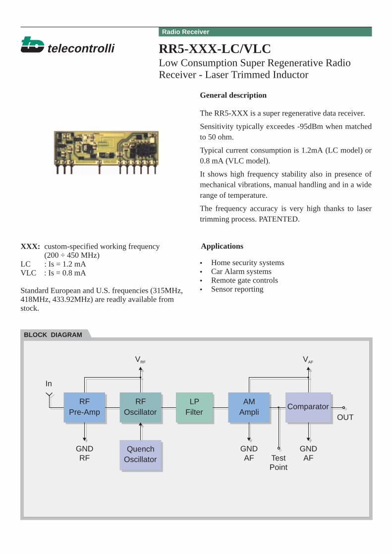
The RR5-XXX is a super regenerative data receiver.
Sensitivity typically exceedes -95dBm when matchedto 50 ohm.
Typical current consumption is 1.2mA (LC model) or0.8 mA (VLC model).
It shows high frequency stability also in presence ofmechanical vibrations, manual handling and in a widerange of temperature.
The frequency accuracy is very high thanks to lasertrimming process. PATENTED.
General description
Applications
In
BLOCK DIAGRAM
XXX: custom-specified working frequency(200 ÷ 450 MHz)
LC : Is = 1.2 mAVLC : Is = 0.8 mA
Standard European and U.S. frequencies (315MHz,418MHz, 433.92MHz) are readly available fromstock.
••••
Home security systemsCar Alarm systemsRemote gate controlsSensor reporting
Radio Receiver
LPFilter
QuenchOscillator
ComparatorOUT
GNDRF AF
PointAF
VRF VAF
GNDTest
GND
Pre-Amp OscillatorRF RF AM
Ampli
1 2 7 10 15
telecontrolli
CHARACTERISTICS MIN TYP MAX UNIT
Electrical Characteristics
VRF
VAF
Vol
Voh
IS
TYPICAL APPLICATION
Mechanical DimensionsPin Description
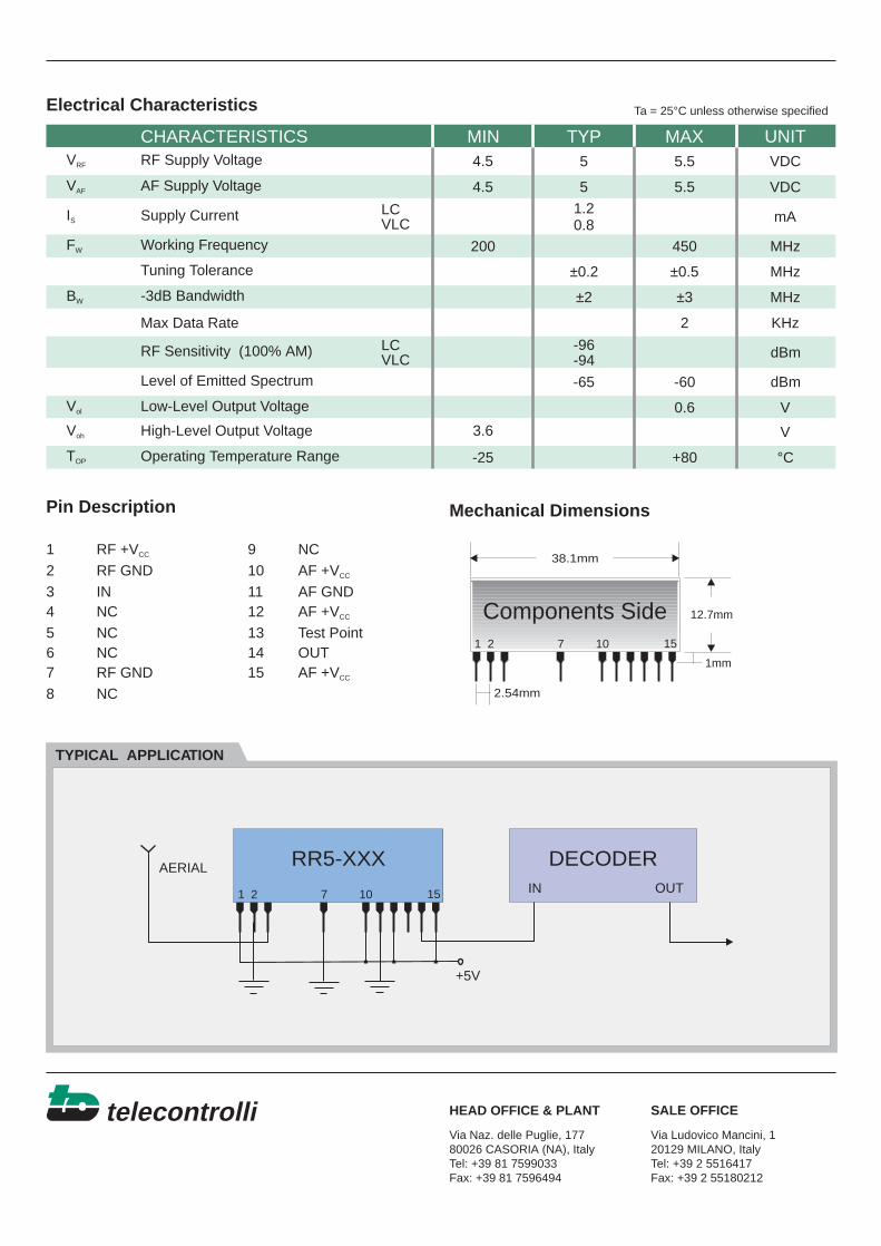
1 RF +V 9 NC2 RF GND 10 AF +V3 IN 11 AF GND4 NC 12 AF +V5 NC 13 Test Point6 NC 14 OUT7 RF GND 15 AF +V8 NC
CC
CC
CC
CC
HEAD OFFICE & PLANT SALE OFFICE
RF Supply Voltage
AF Supply Voltage
Supply Current LCVLC
LCVLC
FW
BW
TOP
Working Frequency
Tuning Tolerance
-3dB Bandwidth
RF Sensitivity (100% AM)
Level of Emitted Spectrum
Low-Level Output Voltage
High-Level Output Voltage
Max Data Rate
Operating Temperature Range
4.5
4.5
200 450
3.6
0.6
-65 -60
5.5
5.5
5
5
VDC
VDC
V
V
1.20.8
±0.2 ±0.5
±2 ±3
2
-96-94
mA
dBm
dBm
MHz
MHz
MHz
KHz
-25 +80 °C
DECODERIN OUT
+5V
AERIAL
38.1mm
12.7mm
2.54mm
1 2 7 10 15
Components Side
1mm
RR5-XXX
Ta = 25°C unless otherwise specified
Via Naz. delle Puglie, 17780026 CASORIA (NA), ItalyTel: +39 81 7599033Fax: +39 81 7596494
Via Ludovico Mancini, 120129 MILANO, ItalyTel: +39 2 5516417Fax: +39 2 55180212
Very Low Consumption Super RegenerativeRadio Receiver - Fast Turn-On Time
telecontrolli RR6-XXX
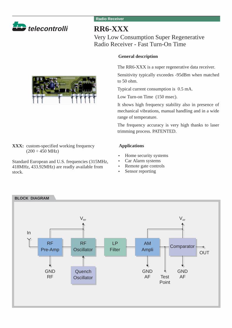
The RR6-XXX is a super regenerative data receiver.
Sensitivity typically exceedes -95dBm when matchedto 50 ohm.
Typical current consumption is 0.5 mA.
Low Turn-on Time (150 msec).
It shows high frequency stability also in presence ofmechanical vibrations, manual handling and in a widerange of temperature.
The frequency accuracy is very high thanks to lasertrimming process. PATENTED.
General description
Applications
In
BLOCK DIAGRAM
XXX: custom-specified working frequency(200 ÷ 450 MHz)
Standard European and U.S. frequencies (315MHz,418MHz, 433.92MHz) are readly available fromstock.
••••
Home security systemsCar Alarm systemsRemote gate controlsSensor reporting
Radio Receiver
LPFilter
QuenchOscillator
ComparatorOUT
GNDRF AF
PointAF
VRF VAF
GNDTest
GND
Pre-Amp OscillatorRF RF AM
Ampli
1 2 7 10 15
telecontrolli
CHARACTERISTICS MIN TYP MAX UNIT
Electrical Characteristics
VRF ,VAF
Vol
Voh
IS
TYPICAL APPLICATION
Mechanical DimensionsPin Description
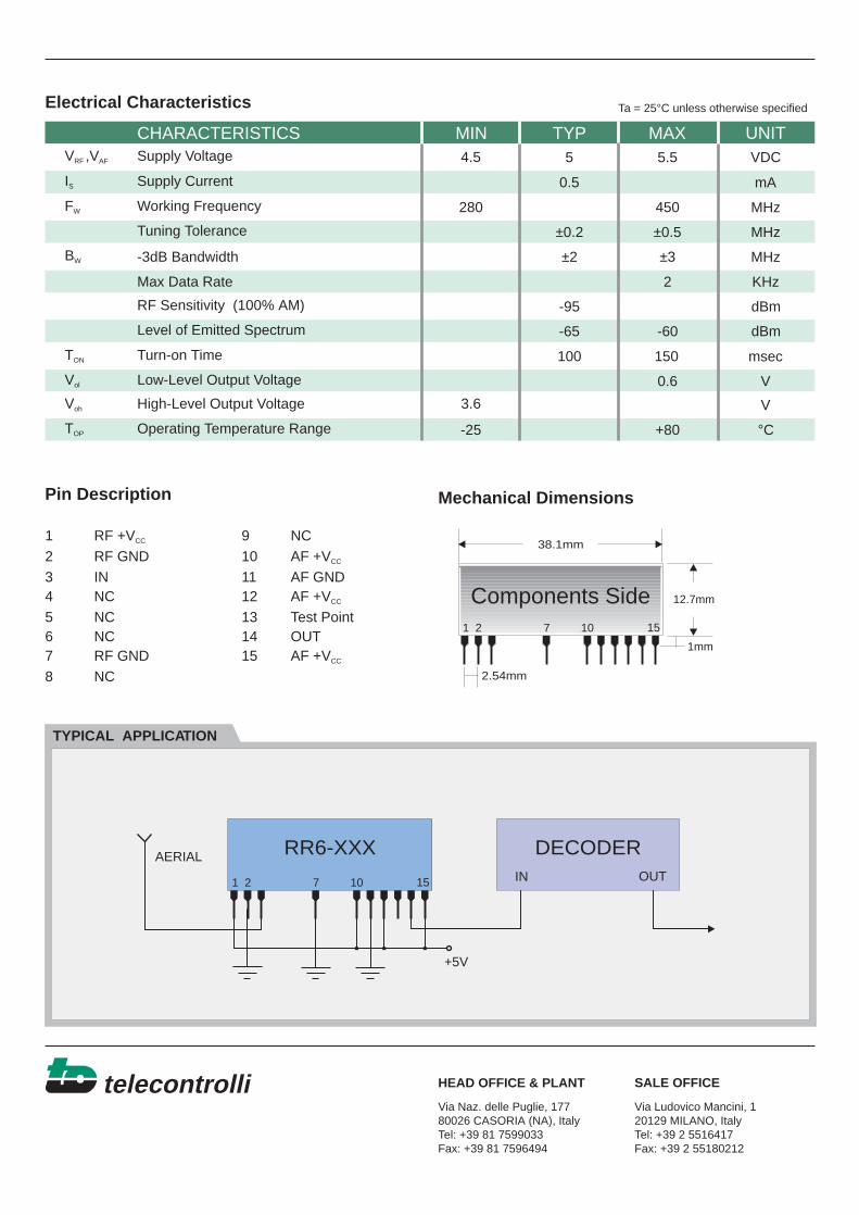
1 RF +V 9 NC2 RF GND 10 AF +V3 IN 11 AF GND4 NC 12 AF +V5 NC 13 Test Point6 NC 14 OUT7 RF GND 15 AF +V8 NC
CC
CC
CC
CC
HEAD OFFICE & PLANT SALE OFFICE
Supply Voltage
Supply Current
FW
BW
TOP
TON
Working Frequency
Tuning Tolerance
-3dB Bandwidth
RF Sensitivity (100% AM)
Level of Emitted Spectrum
Turn-on Time
Low-Level Output Voltage
High-Level Output Voltage
Max Data Rate
Operating Temperature Range
4.5
280 450
3.6
0.6
-65
100
-60
5.55 VDC
V
V
0.5
±0.2 ±0.5
±2 ±3
2
-95
mA
msec
dBm
dBm
MHz
MHz
MHz
KHz
-25 +80 °C
DECODERIN OUT
+5V
AERIAL
38.1mm
12.7mm
2.54mm
1 2 7 10 15
Components Side
1mm
RR6-XXX
Ta = 25°C unless otherwise specified
Via Naz. delle Puglie, 17780026 CASORIA (NA), ItalyTel: +39 81 7599033Fax: +39 81 7596494
Via Ludovico Mancini, 120129 MILANO, ItalyTel: +39 2 5516417Fax: +39 2 55180212
150
AM Superhet Receiver With SAW Front EndFilter
telecontrolli RRS1-XXX
The RRS1-XXX is an AM superhet data receiver withSAW front end filter.
IF Frequency: 500KHz
Typical sensitivity: -100dBm (2.2uVrms)
Supply current: 3.7 mA (typ)
General description
Applications
In
BLOCK DIAGRAM
XXX: custom-specified working frequency(315, 418, 433.92 MHz)
••••
Wireless security systemsCar Alarm systemsRemote gate controlsSensor reporting
Superheterodyne Receiver
MIXERIF
Filter
LocalOscillator
ComparatorOUT
GND
VCC VCC
GND GND
FilterSAW AM
Demodulator
I-ETS 300 220 Compliance
telecontrolli
CHARACTERISTICS MIN TYP MAX UNIT
Electrical Characteristics
VCC
Vol
Voh
IS
TYPICAL APPLICATION
Mechanical DimensionsPin Description
1 V 9 NC2 GND 10 NC3 IN 11 GND4 NC 12 V5 NC 13 NC6 NC 14 OUT7 GND 15 V8 NC
CC
CC
CC
HEAD OFFICE & PLANT SALE OFFICE
Supply Voltage
Supply Current
FR
FIF
TOP
Receiver Frequency
RF Sensitivity (100% AM)*
Level of Emitted Spectrum
Low-Level Output Voltage (I=-10uA)
High-Level Output Voltage (I=200uA)
IF Frequency
Max Data Rate
Operating Temperature Range
4.5
V - 0.5CC
0.6
-65 -60
5.55
5
VDC
V
V
3.7
3
-100
mA
dBm
dBm
315/418/433.92 MHz
500 KHz
KHz
-25 +80 °C
45.72mm
19.05mm
2.54mm
1 2 7 11 15
Components Side
1 2 7 11 15
RRS1-XXX DECODER
IN OUT
+5V
AERIAL
1mm
Ta = 25°C unless otherwise specified
Via Naz. delle Puglie, 17780026 CASORIA (NA), ItalyTel: +39 81 7599033Fax: +39 81 7596494
Via Ludovico Mancini, 120129 MILANO, ItalyTel: +39 2 5516417Fax: +39 2 55180212
* Best Performances are obtained utilizing a transmitted coding with a DC average value indipendent of the data content (BiPhase Manchester coding)
AM Superhet Receiver
telecontrolli RRS2-XXX
The RRS2-XXX is an AM superhet data receiver withLC Front End Filter.
IF Frequency: 500KHz
Typical sensitivity: -102dBm (1.8uVrms)
Supply current: 3.7 mA (typ)
General description
Applications
XXX: custom-specified working frequency(315, 418, 433.92 MHz)
••••
Wireless security systemsCar Alarm systemsRemote gate controlsSensor reporting
Superheterodyne Receiver
In
BLOCK DIAGRAM
MIXERIF
Filter
LocalOscillator
ComparatorOUT
GND
VCC VCC
GND GND
FilterLC AM
Demodulator
telecontrolli
CHARACTERISTICS MIN TYP MAX UNIT
Electrical Characteristics
VCC
Vol
Voh
IS
TYPICAL APPLICATION
Mechanical DimensionsPin Description
1 IN
5 GND
9 GND
10 VCC
12 OUT
HEAD OFFICE & PLANT SALE OFFICE
Supply Voltage
Supply Current
FR
FIF
TOP
Receiver Frequency
RF Sensitivity (100% AM)*
Level of Emitted Spectrum
Low-Level Output Voltage (I=-10uA)
High-Level Output Voltage (I=200uA)
IF Frequency
Max Data Rate
Operating Temperature Range
4.5
V - 0.5CC
0.6
-50
5.55
5
VDC
V
V
3.7
3
-102
mA
dBm
dBm
MHz
500 KHz
KHz
-25 +80 °C
30.48mm
20.32mm
1 95 10 12
Components Side
951 10 12
RRS2-XXX DECODER
IN OUT
+5V
AERIAL
1mm
Ta = 25°C unless otherwise specified
315/418/433.92
Via Naz. delle Puglie, 17780026 CASORIA (NA), ItalyTel: +39 81 7599033Fax: +39 81 7596494
Via Ludovico Mancini, 120129 MILANO, ItalyTel: +39 2 5516417Fax: +39 2 55180212
2.54mm
* Best Performances are obtained utilizing a transmitted coding with a DC average value indipendent of the data content (BiPhase Manchester coding)
Radio Transmitter Module (Integrated Antenna)
telecontrolli RT1-XXX
The RT1-XXX is an hybrid circuit that allows torealize a complete radio transmitter adding a codingcircuit.The Frequency accuracy is very high thanks to lasertrimming process. PATENTED
It shows stable electric characteristics thanks to the"Thick film hybrid" technology.
XXX : working frequency (418, 433.92 MHz)
General description
Features Applications
VCC
In
CIRCUIT SCHEMATIC
•••
Integrated AntennaHigh ReliabilityLaser Trimming Process
••••
Wireless security systemsCar Alarm systemsRemote gate controlsSensor reporting
Radio Transmitter
telecontrolli
CHARACTERISTICS MIN TYP MAX UNIT
Electrical Characteristics
VCC
IS
TYPICAL APPLICATION
Mechanical DimensionsPin Description
19.0 mm
17.78 mm
12
3 4
1 GND Ground
2 IN Modulation Input
3 NC Not Connected
4 V Supply VoltageCC
Via Naz. delle Puglie, 17780026 CASORIA (NA), ItalyTel: +39 81 7599033Fax: +39 81 7596494
Via Ludovico Mancini, 120129 MILANO, ItalyTel: +39 2 5516417Fax: +39 2 55180212
HEAD OFFICE & PLANT SALE OFFICE
Supply Voltage
Supply Current
FW
TOP
Working Frequency
Tuning Tolerance
Max Data Rate
Operating Temperature Range
9 14 VDC
3 mA
418/433.92 MHz
MHz
4 KHz
-25 +80 °C
1
2
3
4
5
6
7
8 9
10
11
12
13
14
15
16MC145026
RT1In
Vcc
GND
Led
12V
+
Ta = 25°C unless otherwise specified
±0.2 ±0.5
5.08 mm 7.6 mm
TOP VIEW
Radio Transmitter Module with SAW Resonator(Integrated Antenna)
telecontrolli RT2-XXX
The RT2-XXX is an hybrid circuit that allows torealize a complete radio transmitter adding a codingcircuit.It shows stable electric characteristics thanks to the"Thick film hybrid" technology.
XXX : working frequency (418, 433.92 MHz)
General description
Features Applications
VCC
In
CIRCUIT SCHEMATIC
•••
Integrated AntennaHigh ReliabilityDIL Package
••••
Wireless security systemsCar Alarm systemsRemote gate controlsSensor reporting
Radio Transmitter
I-ETS 300 220 Compliance (RT2-433.92)
telecontrolli
CHARACTERISTICS MIN TYP MAX UNIT
Electrical Characteristics
VCC
IS
TYPICAL APPLICATION
Mechanical DimensionsPin Description
17.78 mm
10.16 mm1
2 3
4
1 V Supply Voltage
2 GND Ground
3 IN Modulation Input
4 NC Not Connected
CC
HEAD OFFICE & PLANT SALE OFFICE
Supply Voltage
Supply Current
FW
TOP
Working Frequency
Max Data Rate
Operating Temperature Range
4 14 VDC
3 mA
418/433.92 MHz
4 KHz
-40 +80 °C
1
2
3
4
5
6
7
8 9
10
11
12
13
14
15
16MC145026
RT2In
Vcc
GND
Led
12V
+
Ta = 25°C unless otherwise specified
Via Naz. delle Puglie, 17780026 CASORIA (NA), ItalyTel: +39 81 7599033Fax: +39 81 7596494
Via Ludovico Mancini, 120129 MILANO, ItalyTel: +39 2 5516417Fax: +39 2 55180212
5.08 mm
TOP VIEW
Radio Transmitter Module with SAW Resonatorand External Antenna
telecontrolli RT4-XXX
The RT4-XXX is an hybrid circuit that allows torealize a complete radio transmitter adding a codingcircuit.
It shows stable electric characteristics thanks to the"Thick film hybrid" technology.
XXX : working frequency (315, 418, 433.92 MHz)
General description
Features Applications
VCC
In
EA
CIRCUIT SCHEMATIC
••
High ReliabilityDIL Package
••••
Wireless security systemsCar Alarm systemsRemote gate controlsSensor reporting
Radio Transmitter
I-ETS 300 220 Compliance (RT4-433.92-IETS)
telecontrolli
CHARACTERISTICS MIN TYP MAX UNIT
Electrical Characteristics
VCC
VCC
IS
FW
TYPICAL APPLICATION
Mechanical DimensionsPin Description
17.78 mm
10.16 mm1
2 3
4
1 V Supply Voltage
2 GND Ground
3 IN Modulation Input
4 EA External Antenna
CC
HEAD OFFICE & PLANT SALE OFFICE
Supply Voltage
Working Frequency
Supply Current (Vcc=5V IN=1KHz Square Wawe)
TOP
PO
VIH
Max Data Rate
Harmonic Spurious Emission
Input High Voltage
TOP VIEW
Operating Temperature Range
RF Output Power into 50Ω (Vi=5V, Vcc=12V)
2
2
14
433.92
VDC
V
4
303.8
7
mA
dBm
dBc-30
4 KHz
MHz
-25 +80 °C
1
2
3
4
5
6
7
8 9
10
11
12
13
14
15
16MC145026
RT4In
Vcc
GND
EA
Led
12V
+
Ta = 25°C unless otherwise specified
Via Naz. delle Puglie, 17780026 CASORIA (NA), ItalyTel: +39 81 7599033Fax: +39 81 7596494
Via Ludovico Mancini, 120129 MILANO, ItalyTel: +39 2 5516417Fax: +39 2 55180212
Tipically, equipment utilizing this device requires emissions testing and government approval, wich is the responsibility of the equipment manufacturer .
5.08 mm
10
Radio Transmitter Module with SAW Resonatorand External Antenna
telecontrolli RT5-XXX
The RT5-XXX is an hybrid circuit that allows torealize a complete radio transmitter adding a codingcircuit.
It shows stable electric characteristics thanks to the"Thick film hybrid" technology.
XXX : working frequency (315, 418, 433.92 MHz)
General description
Features Applications
VCC
In
EA
CIRCUIT SCHEMATIC
••
High ReliabilitySIL Package
••••
Wireless security systemsCar Alarm systemsRemote gate controlsSensor reporting
Radio Transmitter
telecontrolli
CHARACTERISTICS MIN TYP MAX UNIT
Electrical Characteristics
VCC
VCC
IS
FW
TYPICAL APPLICATION
Mechanical DimensionsPin Description
1 EA External Antenna
2 IN Modulation Input
6 GND Ground
7 VCC Supply Voltage
HEAD OFFICE & PLANT SALE OFFICE
Supply Voltage
Working Frequency
Supply Current (Vcc=5V IN=1KHz Square Wawe)
TOP
PO
VIH
Max Data Rate
Harmonic Spurious Emission
Input High Voltage
Operating Temperature Range
RF Output Power into 50Ω (Vi=5V, Vcc=12V)
2
2
14
433.92
VDC
V
3
303.8
7
mA
dBm
dBc-35
4 KHz
MHz
-25 +80 °C
1
2
3
4
5
6
7
8 9
10
11
12
13
14
15
16MC145026
RT5In
Vcc
GND
EA
Led
12V
+
Ta = 25°C unless otherwise specified
Via Naz. delle Puglie, 17780026 CASORIA (NA), ItalyTel: +39 81 7599033Fax: +39 81 7596494
Via Ludovico Mancini, 120129 MILANO, ItalyTel: +39 2 5516417Fax: +39 2 55180212
Tipically, equipment utilizing this device requires emissions testing and government approval, wich is the responsibility of the equipment manufacturer .
11.43mm
1 62 7
Components Side
1mm
17.78mm
2.54mm
10
Radio Transmitter Module with SAW Resonatorand External Antenna
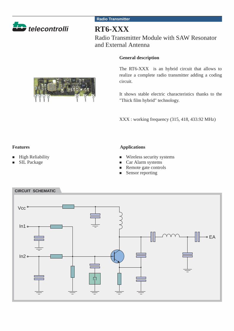
telecontrolli RT6-XXX
The RT6-XXX is an hybrid circuit that allows torealize a complete radio transmitter adding a codingcircuit.
It shows stable electric characteristics thanks to the"Thick film hybrid" technology.
XXX : working frequency (315, 418, 433.92 MHz)
General description
Features Applications
Vcc
In2
In1
EA
CIRCUIT SCHEMATIC
+
+
High ReliabilitySIL Package
+
+
+
+
Wireless security systemsCar Alarm systemsRemote gate controlsSensor reporting
Radio Transmitter
telecontrolli
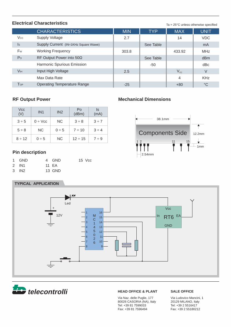
CHARACTERISTICS MIN TYP MAX UNIT
Electrical Characteristics
VCC
VCC
IS
FW
TYPICAL APPLICATION
Mechanical DimensionsRF Output Power
Pin description
HEAD OFFICE & PLANT SALE OFFICE
Supply Voltage
Working Frequency
Supply Current (IN=1KHz Square Wawe)
TOP
PO
VIH
Max Data Rate
Harmonic Spurious Emission
Input High Voltage
Operating Temperature Range
RF Output Power into 50Ω
2.7
2.5
14
433.92
VDC
V
See Table
See Table
303.8
mA
dBm
dBc-50
4 KHz
MHz
-25 +80 °C
1
2
3
4
5
6
7
8 9
10
11
12
13
14
15
16MC145026
RT6In
Vcc
GND
EA
Led
12V
+
Ta = 25°C unless otherwise specified
Via Naz. delle Puglie, 17780026 CASORIA (NA), ItalyTel: +39 81 7599033Fax: +39 81 7596494
Via Ludovico Mancini, 120129 MILANO, ItalyTel: +39 2 5516417Fax: +39 2 55180212
38.1mm
12.2mm
2.54mm
1 2 11 15
Components Side
1mm
1 GND 4 GND 15 Vcc2 IN1 11 EA3 IN2 13 GND
Vcc(V) IN1 IN2
Po(dBm)
Is(mA)
3 ÷ 5
5 ÷ 8
8 ÷ 12
0 ÷ Vcc
NC
0 ÷ 5
0 ÷ 5
NC
NC
3 ÷ 8 3 ÷ 7
3 ÷ 4
7 ÷ 9
7 ÷ 10
12 ÷ 15
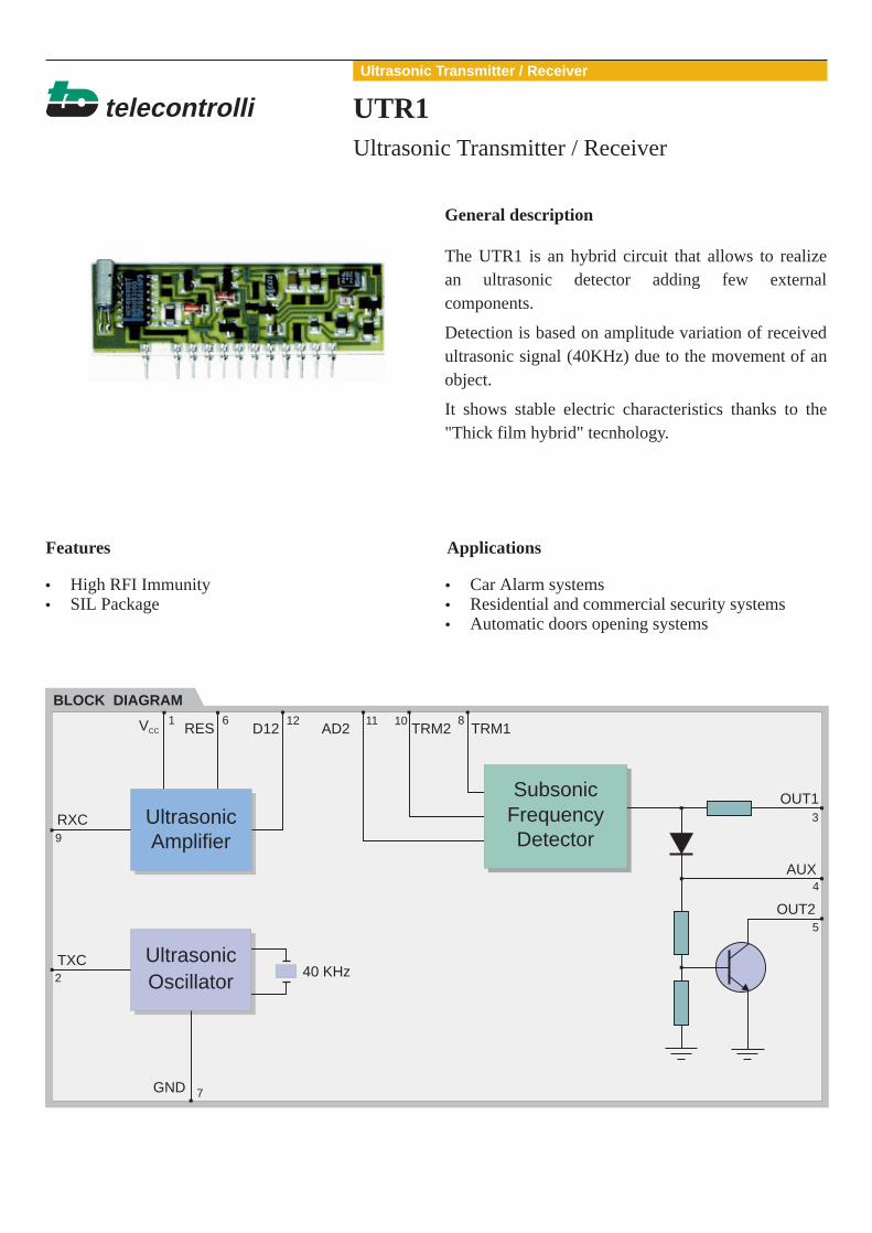
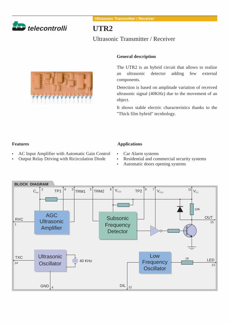
Ultrasonic Transmitter / Receiver
telecontrolli UTR1
The UTR1 is an hybrid circuit that allows to realizean ultrasonic detector adding few externalcomponents.
Detection is based on amplitude variation of receivedultrasonic signal (40KHz) due to the movement of anobject.
It shows stable electric characteristics thanks to the"Thick film hybrid" tecnhology.
General description
ApplicationsFeatures
BLOCK DIAGRAM
••
High RFI ImmunitySIL Package
•••
Car Alarm systemsResidential and commercial security systemsAutomatic doors opening systems
Ultrasonic Transmitter / Receiver
OUT1
TRM1TRM2AD2D121
9
2
7
3
4
5
6 12 11 10 8RES
RXC
OUT2
AUX
GND
40 KHzTXC
VCC
SubsonicFrequencyDetector
UltrasonicAmplifier
UltrasonicOscillator
telecontrolli
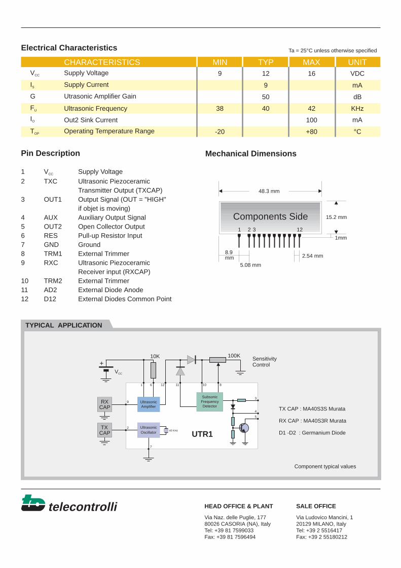
CHARACTERISTICS MIN TYP MAX UNIT
Electrical Characteristics
VCC
IS
TYPICAL APPLICATION
Mechanical DimensionsPin Description
1 V Supply Voltage2 TXC Ultrasonic Piezoceramic
Transmitter Output (TXCAP)3 OUT1 Output Signal (OUT = "HIGH"
if objet is moving)4 AUX Auxiliary Output Signal5 OUT2 Open Collector Output6 RES Pull-up Resistor Input7 GND Ground8 TRM1 External Trimmer9 RXC Ultrasonic Piezoceramic
Receiver input (RXCAP)10 TRM2 External Trimmer11 AD2 External Diode Anode12 D12 External Diodes Common Point
CC
HEAD OFFICE & PLANT SALE OFFICE
Supply Voltage
Supply Current
G
FU
IO
TOP
Utrasonic Amplifier Gain
Operating Temperature Range
Ultrasonic Frequency
Out2 Sink Current
9 1612 VDC
9
100
-20 +80
mA
°C
50 dB
40 4238 KHz
mA
1 2 3 12
Components Side
Ta = 25°C unless otherwise specified
15.2 mm
48.3 mm
8.9mm
5.08 mm
2.54 mm
1mm
100K10K SensitivityControl
TX CAP : MA40S3S Murata
RX CAP : MA40S3R Murata
D1 -D2 : Germanium Diode
Component typical values
1
9
2
7
3
4
5
6 12 11 10 8
40 KHz
SubsonicFrequencyDetector
UltrasonicAmplifier
UltrasonicOscillator UTR1
RXCAP
TXCAP
VCC
+
Via Naz. delle Puglie, 17780026 CASORIA (NA), ItalyTel: +39 81 7599033Fax: +39 81 7596494
Via Ludovico Mancini, 120129 MILANO, ItalyTel: +39 2 5516417Fax: +39 2 55180212
Ultrasonic Transmitter / Receiver
telecontrolli UTR2
The UTR2 is an hybrid circuit that allows to realizean ultrasonic detector adding few externalcomponents.
Detection is based on amplitude variation of receivedultrasonic signal (40KHz) due to the movement of anobject.
It shows stable electric characteristics thanks to the"Thick film hybrid" tecnhology.
General description
ApplicationsFeatures
BLOCK DIAGRAM
••
AC Input Amplifier with Automatic Gain ControlOutput Relay Driving with Ricirculation Diode
•••
Car Alarm systemsResidential and commercial security systemsAutomatic doors opening systems
Ultrasonic Transmitter / Receiver
OUT
TRM1 TRM22
1
14
4 12
15
13
6 3 5 8 9 7 11TP1 TP2
RXC
LED
GND DIL
40 KHz1K
10K
TXC
CextVCC2 VCC3 VCC
UltrasonicAmplifier
AGC
UltrasonicOscillator
LowFrequencyOscillator
SubsonicFrequencyDetector
telecontrolli
CHARACTERISTICS MIN TYP MAX UNIT
Electrical Characteristics
VCC
IS
TYPICAL APPLICATION
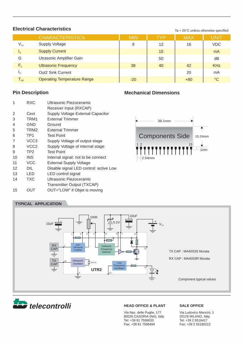
Mechanical DimensionsPin Description
1 RXC Ultrasonic PiezoceramicReceiver Input (RXCAP)
2 Cext Supply Voltage External Capacitor3 TRM1 External Trimmer4 GND Ground5 TRM2 External Trimmer6 TP1 Test Point7 VCC3 Supply Voltage of output stage8 VCC2 Supply Voltage of internal stage9 TP2 Test Point10 INS Internal signal: not to be connect11 VCC External Supply Voltage12 DIL Disable signal LED control: active Low13 LED LED control signal14 TXC Ultrasonic Piezoceramic
Transmitter Output (TXCAP)15 OUT OUT="LOW" if Objet is moving
HEAD OFFICE & PLANT SALE OFFICE
Supply Voltage
Supply Current
G
FU
IO
TOP
Utrasonic Amplifier Gain
Operating Temperature Range
Ultrasonic Frequency
Out2 Sink Current
9 1612 VDC
15
20
-20 +80
mA
°C
50 dB
40 4238 KHz
mA
Ta = 25°C unless otherwise specified
100K 10uF
10uF 5.1V
TX CAP : MA40S3S Murata
RX CAP : MA40S3R Murata
Component typical values
RXCAP
TXCAP
VCC
2
1
14
4 12
15
13
6 3 5 8 9 7 11
40 KHz
UltrasonicAmplifier
AGC
UltrasonicOscillator Low
FrequencyOscillator
SubsonicFrequencyDetector
+
+ +
38.1mm
15.24mm
2.54mm
1 2 15
Components Side
1mm
UTR2
Via Naz. delle Puglie, 17780026 CASORIA (NA), ItalyTel: +39 81 7599033Fax: +39 81 7596494
Via Ludovico Mancini, 120129 MILANO, ItalyTel: +39 2 5516417Fax: +39 2 55180212
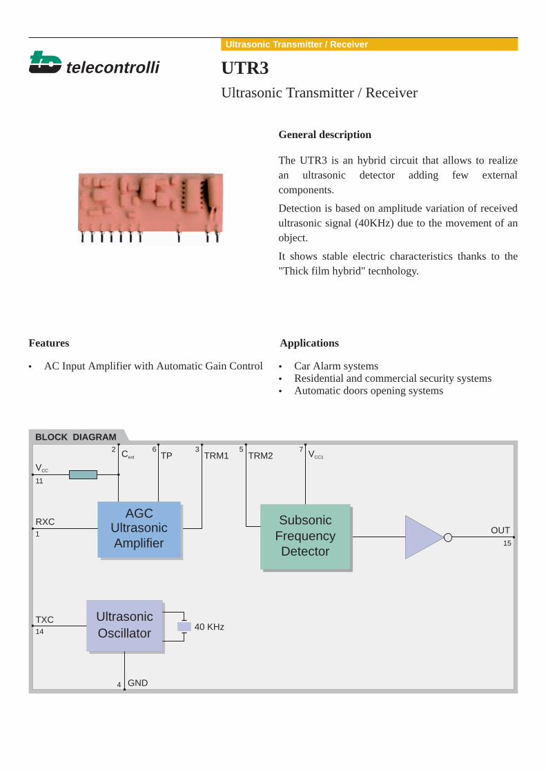
Ultrasonic Transmitter / Receiver
telecontrolli UTR3
The UTR3 is an hybrid circuit that allows to realizean ultrasonic detector adding few externalcomponents.
Detection is based on amplitude variation of receivedultrasonic signal (40KHz) due to the movement of anobject.
It shows stable electric characteristics thanks to the"Thick film hybrid" tecnhology.
General description
ApplicationsFeatures
BLOCK DIAGRAM
• AC Input Amplifier with Automatic Gain Control •••
Car Alarm systemsResidential and commercial security systemsAutomatic doors opening systems
Ultrasonic Transmitter / Receiver
OUT
TRM1 TRM22
1
14
4
15
6 3 5 7
11
TP
RXC
GND
40 KHzTXC
Cext VCC1
VCC
UltrasonicAmplifier
AGC
UltrasonicOscillator
SubsonicFrequencyDetector
telecontrolli
CHARACTERISTICS MIN TYP MAX UNIT
Electrical Characteristics
VCC
VCC1
IS
TYPICAL APPLICATION
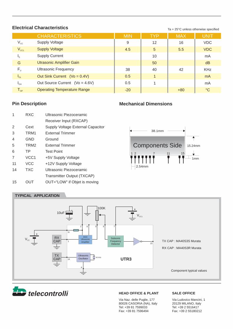
Mechanical DimensionsPin Description
1 RXC Ultrasonic Piezoceramic
Receiver Input (RXCAP)
2 Cext Supply Voltage External Capacitor
3 TRM1 External Trimmer
4 GND Ground
5 TRM2 External Trimmer
6 TP Test Point
7 VCC1 +5V Supply Voltage
11 VCC +12V Supply Voltage
14 TXC Ultrasonic Piezoceramic
Transmitter Output (TXCAP)
15 OUT OUT="LOW" if Objet is moving
HEAD OFFICE & PLANT SALE OFFICE
Supply Voltage
Supply Voltage
Supply Current
G
FU
IOL
IOH
TOP
Utrasonic Amplifier Gain
Operating Temperature Range
Ultrasonic Frequency
Out Sink Current (Vo = 0.4V)
Out Source Current (Vo = 4.6V)
9
4.5 5 5.5
1612 VDC
VDC
10
1
1
-20 +80
mA
°C
50 dB
40 4238
0.5
0.5
KHz
mA
mA
Ta = 25°C unless otherwise specified
100K10uF
TX CAP : MA40S3S Murata
RX CAP : MA40S3R Murata
Component typical values
RXCAP
TXCAP
VCC1
VCC
+ +
+
38.1mm
15.24mm
2.54mm
1 2 7 11 15
Components Side
1mm
Via Naz. delle Puglie, 17780026 CASORIA (NA), ItalyTel: +39 81 7599033Fax: +39 81 7596494
Via Ludovico Mancini, 120129 MILANO, ItalyTel: +39 2 5516417Fax: +39 2 55180212
2
1
14
4
15
6 3 5 7
11
40 KHz
UltrasonicAmplifier
AGC
UltrasonicOscillator
SubsonicFrequencyDetector
UTR3

Passive Infrared Detector
telecontrolli PID1
The PID1 is an hybrid circuit that allows to realize apassive infrared detector adding few externalcomponents.
Detection is based on infrared radiations emitted byhuman body.
It shows stable electric characteristics thanks to the"Thick film hybrid" tecnhology.
General description
ApplicationsFeatures
BLOCK DIAGRAM
••
High RFI ImmunitySIL Package
••
Residential and commercial security systemsAutomatic doors opening systems
Infrared Devices
OUT1
TRM1 TRM2CAP+4
14
2
3
1 5-9-1316 15
12
11
10
6 7 8CAP-
IRD
IN
Cext
OUT
LED
GND
to internalcircuit
+5V 1K
VCC VCC2 VCC1
SubsonicAmplifier
LinearRegulator
Detector Driver
telecontrolli
CHARACTERISTICS MIN TYP MAX UNIT
Electrical Characteristics
VCC
IS
TYPICAL APPLICATION
Mechanical DimensionsPin Description
1 GND Ground2 IN Infrared Sensor Input3 Cext External Capacitor4 CAP- External Capacitor (-)5-9-13 Vcc1 Supply Voltage of Internal Stage6 CAP+ External Capacitor (+)7 TRM1 External Trimmer8 TRM2 External Trimmer10 Out1 Output Signal (active low)11 LED Led Control Signal12 Out Output Signal (active high)14 IRD Infrared Sensor Drain15 Vcc2 +12V Output Voltage16 Vcc Input Supply Voltage
HEAD OFFICE & PLANT SALE OFFICE
Supply Voltage
Supply Current
G
BW
IO
TOP
Amplifier Gain
Operating Temperature Range
Amplifier Bandwidth
Out2 Sink Current
9 1612 VDC
5
20
-10 +70
mA
°C
70 dB
101 KHz
mA
1 16
Components Side
Ta = 25°C unless otherwise specified
15.24 mm
40.64 mm
2.54 mm
1mm
100K
Relè
LED47uF
47uF
47uF
47uF
SensitivityControl
Pyroelectric IR sensor : Heimann LHi954
IRSensor
VCC2
VCC2
+
+
+
+
+
4
14
2
3
1 5-9-1316 15
12
11
10
6 7 8
+5V1K
SubsonicAmplifier
LinearRegulator
Detector Driver
PID1
Via Naz. delle Puglie, 17780026 CASORIA (NA), ItalyTel: +39 81 7599033Fax: +39 81 7596494
Via Ludovico Mancini, 120129 MILANO, ItalyTel: +39 2 5516417Fax: +39 2 55180212
Component typical values
Infrared Pulse Transmitter
telecontrolli IRT1
The IRT1 is an hybrid circuit that allows to realize aninfrared barrier when utilized with an infrared pulsedetector (IRD1).
It shows stable electric characteristics thanks to the"Thick film hybrid" tecnhology.
General description
ApplicationsFeatures
BLOCK DIAGRAM
••
High RFI ImmunitySIL Package
••
Residential and commercial security systemsAutomatic doors opening systems
Infrared Devices
VCC
GNDIRED
4
1
5
telecontrolli
CHARACTERISTICS MIN TYP MAX UNIT
Electrical Characteristics
VCC
IS
TYPICAL APPLICATION
Mechanical DimensionsPin Description
1 GND Ground
4 Vcc Supply Voltage
5 IRED Infrared Emitting Diode
HEAD OFFICE & PLANT SALE OFFICE
Supply Voltage
Supply Current
Tp
FIR
TOP Operating Temperature Range
Pulse Width
Infrared Pulse Frequency
9 108 VDC
35
400300
40
-20 +80
mA
µsec
Hz
°C
Ta = 25°C unless otherwise specified
Relè
LED100uF12V
Photodiode
IRD1 = Infrared Pulse Detector(see Data Sheet)
Component typical values
VCC
VCC
+ +
Via Naz. delle Puglie, 17780026 CASORIA (NA), ItalyTel: +39 81 7599033Fax: +39 81 7596494
Via Ludovico Mancini, 120129 MILANO, ItalyTel: +39 2 5516417Fax: +39 2 55180212
1 54
ComponentsSide 16.9 mm
2.54 mm
1mm
12.7 mm
IRT1IRD1
1
4 5
InfraredEmittingDiode
IRED: TSHA 5200 - 5203 TemicPhotodiode: BPW 43 - BP104 Temic
Infrared Pulse Detector
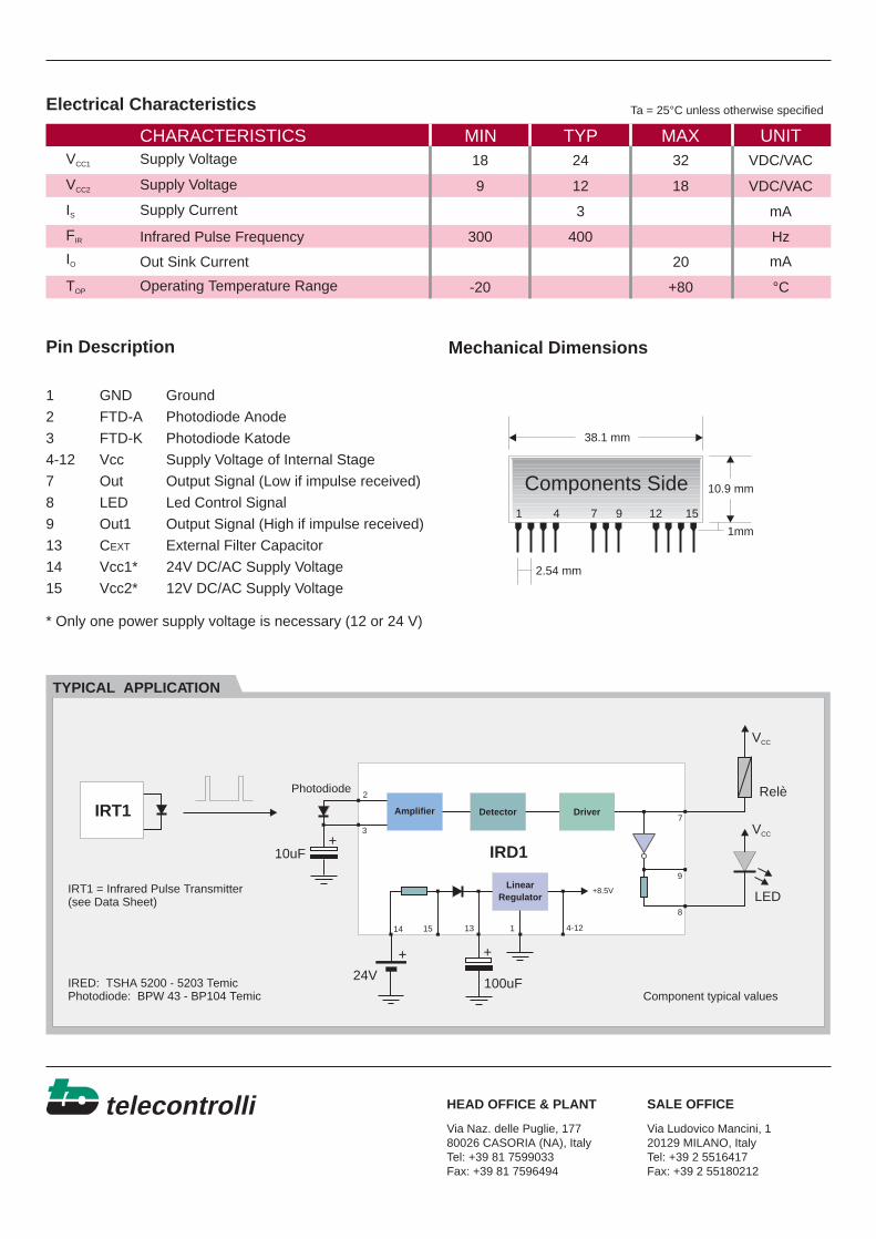
telecontrolli IRD1
The IRD1 is an hybrid circuit that allows to realize aninfrared barrier when utilized with an infrared pulsetransmitter (IRT1).
IRD1 detect IR pulses and activate the output signalwhen the barrier is interrupted by an object.
It shows stable electric characteristics thanks to the"Thick film hybrid" tecnhology.
General description
ApplicationsFeatures
BLOCK DIAGRAM
••
High RFI ImmunitySIL Package
••
Residential and commercial security systemsAutomatic doors opening systems
Infrared Devices
OUT1
3
2
1 4-121514 13
7
8
9
FTD-K
FTD-A
OUT
LED
GND
to internalcircuit
+8.5V2.2K
VCC1 VCC2 CEXT VCC
Amplifier
LinearRegulator
Detector Driver
telecontrolli
CHARACTERISTICS MIN TYP MAX UNIT
Electrical Characteristics
VCC1
VCC2
IS
TYPICAL APPLICATION
Mechanical DimensionsPin Description
1 GND Ground
2 FTD-A Photodiode Anode
3 FTD-K Photodiode Katode
4-12 Vcc Supply Voltage of Internal Stage
7 Out Output Signal (Low if impulse received)
8 LED Led Control Signal
9 Out1 Output Signal (High if impulse received)
13 C External Filter Capacitor
14 Vcc1* 24V DC/AC Supply Voltage
15 Vcc2* 12V DC/AC Supply Voltage
* Only one power supply voltage is necessary (12 or 24 V)
EXT
HEAD OFFICE & PLANT SALE OFFICE
Supply Voltage
Supply Voltage
Supply Current
IO
FIR
TOP Operating Temperature Range
Out Sink Current
Infrared Pulse Frequency
2418 32 VDC/VAC
VDC/VAC129 18
3
400300
20
-20 +80
mA
Hz
°C
mA
Ta = 25°C unless otherwise specified
Relè
LED
100uF24V
10uF
Photodiode
IRT1 = Infrared Pulse Transmitter(see Data Sheet)
Component typical values
VCC
VCC
+ +
3
2
1 4-121514 13
7
8
9
+8.5V
Amplifier
LinearRegulator
Detector Driver
IRD1
Via Naz. delle Puglie, 17780026 CASORIA (NA), ItalyTel: +39 81 7599033Fax: +39 81 7596494
Via Ludovico Mancini, 120129 MILANO, ItalyTel: +39 2 5516417Fax: +39 2 55180212
1 7 9 124 15
Components Side 10.9 mm
2.54 mm
1mm
38.1 mm
+
IRT1
IRED: TSHA 5200 - 5203 TemicPhotodiode: BPW 43 - BP104 Temic