Embed Size (px)
Citation preview

The Sea Fish Industry AuthoritySeafish Technology
Remote Closure of Sea Inlets
Seafish Report No. SR547 A. DeanISBN 0903941 06 6 November 2002
© The Sea Fish Industry Authority
Sea Fish Industry AuthoritySeafish Technology
Remote Closure of Sea Inlets
Seafish Report No. SR547 A. DeanNovember 2002
Summary
Over half of fishing vessel losses are attributed to flooding, mainly due to the failureof pipes and fittings in the engineroom. Often, when flooding is discovered the crewfind it impossible to reach and close the sea inlet valves to stop the flow of waterand the vessel is lost. John Buchan, a retired engineer from Peterhead, had aninnovative idea to enable the remote closure of sea inlet valves and this reportdescribes the development of his ‘Hydraclose’ concept and a demonstrationinstallation on a 25.6m vessel.
Companies in Peterhead and Fraserburgh have developed this system and theScottish Executive has given major support by the provision of a FIFG grant towardsthe vessel demonstration costs.
Contents:
Summary
1. Introduction ....................................................................................................... 12. Background ....................................................................................................... 23. Basic Concept ................................................................................................... 34. Development...................................................................................................... 5
4.1 Planning Meeting .................................................................................................................. 74.2 Actuator................................................................................................................................. 7
4.2.1 Sizes.......................................................................................................................... 84.2.2 Mounting.................................................................................................................... 84.2.3 Indicator..................................................................................................................... 84.2.4 Manual Activation ...................................................................................................... 8
4.3 The Pump ............................................................................................................................. 84.4 Allocation of Responsibilities ................................................................................................ 9
5. Prototype Development .................................................................................. 105.1 Actuator design ................................................................................................................... 105.2 Testing ................................................................................................................................ 11
6. Demonstration ................................................................................................. 126.1 Background......................................................................................................................... 126.2 FIFG Grant.......................................................................................................................... 126.3 Shore Tests ........................................................................................................................ 136.4 Installation........................................................................................................................... 136.5 Monitoring ........................................................................................................................... 15
7. Discussion ....................................................................................................... 177.1 Cooling Water ..................................................................................................................... 177.2 Spring Failure...................................................................................................................... 177.3 Closure of Sea Inlets........................................................................................................... 177.4 Manual Operation ............................................................................................................... 177.5 Indicator Light Failure ......................................................................................................... 177.6 Actuator/Valve Stuck in the closed position........................................................................ 18
8. The Future........................................................................................................ 198.1 Commercialisation .............................................................................................................. 198.2 Industry Requirements........................................................................................................ 198.3 Insurers ............................................................................................................................... 20
9. Conclusions..................................................................................................... 2110. Acknowledgements......................................................................................... 22
Figures:Figure 1 - Emergency Sea Inlet Closure System.................................................................. 3Figure 2 – Remote Operation of Seacocks........................................................................... 5Figure 3 – Actuator Design..................................................................................................10Figure 4 – mfv ‘TREASURE’ ...............................................................................................12Figure 5 – Shore Tests........................................................................................................13Figure 6 – Control Position ..................................................................................................14Figure 7 – 100mm Valve .....................................................................................................14Figure 8 – 50mm Valve .......................................................................................................14Figure 9 – Operating Instructions for the ‘Hydraclose’ System ............................................15

Remote Closure of Sea Inlets
Page 1 SR547©Sea Fish Industry Authority
1. IntroductionMarine Accident Investigation Branch (MAIB) statistics from recent years show that54% of all fishing vessel losses occurred through flooding. ‘Downflooding’ in badweather, through doors, hatches or scuttles is the cause in some instances but avery common cause is the failure of pipes and fittings, allowing seawater to flood theengineroom. Unfortunately, all too often, the crew are not aware that flooding isoccurring until the lights fail or the engine stops and upon investigating, they find thatthe engineroom is deep in water and they cannot reach the sea inlet valves to stopthe flow. Two things are essential: an effective alarm system to make the crewaware of flooding and the ability to stop the flow of water.
Bilge level alarms are required by regulation on vessels over 15m and this isobviously a very sensible measure. However, the reliability of many installations onvessels has been poor due to lack of maintenance and the quality of components.Bad siting of float switches can result in repeated false alarms in rough seaconditions making it likely that systems will be switched off. Recently, Banff andBuchan College carried out a valuable study and development work into vesselflooding and the development of a reliable bilge level monitoring system that willaddress the concerns about bilge alarm systems. Given that an effective alarmsystem makes the crew aware of a flooding situation, they then have to be able todo something about it.
When a pipe or a fitting fails, the sea inlet valve feeding the pipe or fitting has to beclosed to stop the water flow. This report describes the innovation of John Buchan, aretired engineer in Peterhead, to achieve a practical, effective system for remoteclosure of sea inlet valves.

Remote Closure of Sea Inlets
Page 2 SR547©Sea Fish Industry Authority
2. BackgroundThe sea inlet valves or ‘seacocks’ installed on vessels used to be ‘quarter turn’ brasstaper cocks that were notorious for sticking. Located low down in the hull they weregenerally difficult to reach and hence, were rarely operated. Thus, because ofinfrequent use, when they did need to be closed it was often with some difficulty asthe cock would be found to have seized. Newer vessels and bigger vessels have‘screw down’ valves fitted on the sea inlets and may well have a ‘ring main’ systemwith branch pipes taking seawater to several locations on the vessel. However,difficult access to the sea inlet valves results in them rarely being operated.
In theory, the sea inlets are to be closed to safeguard the vessel each time it is inport and unattended. In practice, the sea inlets on most vessels are never routinelyclosed and will only be operated when necessary for maintenance. In an emergencysituation, the crew may be faced with the lifting of engineroom floor plates to locatethe valves and when the water is above the plates it is sometimes impossible to beable to reach and close the valves.
Each year there are several incidents in which vessels are taking in water and thecrew cannot control the situation. Tragically, in some instances lives are lost and if itwere not for the ability and dedication of the rescue services, ‘air lifting’ emergencypumps to vessels in trouble, many more vessels would be lost. It was the manyreports that appeared in the fishing and local media about fishing vessels sinkingafter a pipe failed in the engineroom that prompted John Buchan to try to devise apractical, cost effective solution.

Remote Closure of Sea Inlets
Page 3 SR547©Sea Fish Industry Authority
3. Basic ConceptThe remote operation of valves is not new and indeed, valve manufacturers canprovide actuators powered by pneumatics, hydraulics or an electrical motor. Mostsuch systems will be computer controlled and are extensively used in the petro-chemical industries. For fishing vessels, these products are too sophisticated andexpensive and as they invariably require a power input, they could not be reliedupon to work in a ‘dead ship’ situation. With the possible loss of all power, includingelectrical, a manual means of closing the sea inlets is desired, ideally from the top ofthe engineroom. Extension spindles are fitted on some vessels to give goodaccessibility to valves but generally just to floor plate level. Spring loaded closure ispossible, as per fuel shut off valves but these would be expensive in the size ofvalve needed and also, such mechanisms have to be manually reset at the valveeach time it is operated.
Figure 1 – Emergency Sea Inlet Closure System

Remote Closure of Sea Inlets
Page 4 SR547©Sea Fish Industry Authority
One system that offers effective operation with reliability, ease of installation andflexibility is a simple manually powered hydraulic system, very similar to a carbraking system and this concept has been adapted by John Buchan to achieve the‘Hydraclose’ system.
As shown in figure 1, the system comprises a hand operated hydraulic pump thatwill typically be located at the top of the engineroom. The pump feeds a manifoldwith selector valves for each of the sea inlet valves and small bore pipelines connectto hydraulic actuators mounted on each valve. To close any or all valves, simplyopen the respective selector valve, close the pump bypass and operate the pump.
Several strokes of the handle will close all the valves in a few seconds. The selectorvalves are then closed to isolate each valve from the pump. To open any valve,open the appropriate selector and release the pump bypass valve. The actuator will‘spring return’ opening the sea inlet. As a safeguard, in the event of hydraulic failure,a manual means of operation is provided via a socket and ‘T’ bar to screw down ajacking screw in the end of the actuator and close the valve. An alternative to thesocket and ‘T’ bar is to fit a hand wheel to the jacking screw, as has been carried outon the trial installation.

Remote Closure of Sea Inlets
Page 5 SR547©Sea Fish Industry Authority
4. DevelopmentWhen the concept was first conceived it was with the ‘quarter turn’ seacocks inmind. Small double acting hydraulic cylinders were envisaged to rotate the spindlevia a crank. The selector valves were to be two-way to enable the cylinder to bepowered in both directions to ‘open’ and ‘close’ the seacock. See fig 2.
Figure 2 – Remote Operation of Seacocks

Remote Closure of Sea Inlets
Page 6 SR547©Sea Fish Industry Authority
Working on his own, John Buchan built a basic model to demonstrate the systemand then set about approaching people involved with fishing vessels and their safetyto ‘take up’ this safety innovation. Many people were impressed with the conceptand wished him to take it forward but no person or organisation agreed to pursue thedevelopment.
Seafish became involved when the North East Fishermen’s Training Associationforwarded a letter from Mr Buchan as they thought this was a project that Seafishmay be able to help with. Indeed, as vessel flooding had been identified as theforemost cause of vessel losses, Seafish were very keen to consider the concept. Avisit was made to Peterhead to see the working model and to discuss ideas and howto progress. It was appreciated that on the bigger vessels ‘screw down’ valves areinstalled and hence thought must be given to address such valves.
Seafish Report SR 536 ‘Vessel Floodings – A Discussion Document’ was producedand widely circulated around the industry to promote interest and reaction. HSLMarine and Industrial Hydraulic Engineers were contracted to make a display modelin order to demonstrate the system and this model included hydraulic operation of a‘screw down’ sea inlet valve. As suggested by John Buchan, the threaded spindle ofthe valve was simply replaced with a double acting cylinder to lift and lower the valvedisc. The model was shown to many in the fishing industry; skippers, insurers,officials etc., but, although all were impressed with the concept, it was provingdifficult to find commercial interest to take the idea forward and make it commerciallyavailable.
The lack of commercial interest was very disheartening as John Buchan had spentover a year drawing sketches, making models, writing letters and talking to everyonepossible to try to turn a sensible idea into a reality. Fortunately two key people tookan interest.
Bill Taylor, Superintendent Engineer for Grampian Sea Fishing, liked the idea andcould see the benefit of having a means of operating the sea inlets from the top ofthe engineroom. Aside from the emergency situation, the convenience of being ableto quickly close the valves whenever a vessel is left in port would eliminate theincidents in which vessels sink or serious flooding damage occurs when the vesselis unattended. Bill Taylor offered one of the Grampian vessels as a trials vessel todemonstrate and prove the system.
Bill Mackie, of Bill Mackie Engineering Limited in Peterhead also saw the potential ofthe idea. Having worked on many vessels and seen all the possible problems thatcan and do occur of pipes and fittings failing, obstructions on valve seats, backsiphoning etc., a system to enable the sea inlets to be readily closed had to beworthwhile. He agreed to work with John Buchan, Bill Taylor and Seafish to try tomake the ‘Hydraclose’ concept a reality.

Remote Closure of Sea Inlets
Page 7 SR547©Sea Fish Industry Authority
4.1 Planning MeetingA meeting was organised with all persons present and including Brian Wilson, theSeafish Marine Surveyor for Scotland, to discuss the concept and how it should bedeveloped. The display model was considered carefully to find ways of improving orsimplifying the system. The model was of a double acting cylinder, being powered inboth directions to open and close the sea inlet valve. This requires a two-pipesystem with two-way change over valves and an obvious thought was could this besimplified by using a single acting system?
A concern with hydraulics is; what happens if they fail, could a leak or a broken piperesult in the sea inlet being inoperable? Obviously, a broken pipe would preventhydraulic operation of the valve and hence there must be a manual means ofoperation as a back up. Also, because this would be a ‘passive’ hydraulic systemwithout pressure continually being generated to hold the cylinder in place, was itlikely that the sea inlet valve could, over time, slowly close? This was considered tobe a possibility and one that had to be addressed.
Bill Mackie pointed out that the essential requirement for the vessel was that coolingwater was maintained to the engines and therefore any failing of the system mustresult in the sea inlet remaining open. He suggested that a single acting cylindershould be used with a spring to hold the valve open and hydraulic pressure used toclose it. A jacking screw in the end of the cylinder would facilitate manual closureand also serve to lock the valve closed when desired.
This design concept resolved all the concerns that had been expressed and it wasagreed to proceed on that basis. To prove the system it would be necessary todemonstrate it on a vessel and the MFV TREASURE, a 25.6m trawler operated byGrampian Sea Fishing was chosen. This vessel has a ‘ring main’ sea water systemwith 100mm valves at port and starboard. In addition it has two 50mm sea inlets forauxiliary engines. Substitute valves were ordered to enable actuators to be mountedand tests undertaken without major disruption to the vessel.
4.2 ActuatorFrom the discussions it was appreciated that the design and manufacture of theactuator was the key to the whole system and that it would be preferable to havethem made by a specialist company with the appropriate technology. Small hydrauliccylinders had been used on the display model and John Buchan experimented witha similar cylinder fitted with a return spring. ‘Stiction’ of the seals was a problem, asthe drag of the piston seals and rod gland was high in relation to the available forcefrom a spring. Obviously, such seals are designed to work at high pressure and forthe actuator application, high pressure is not needed. Indeed, the pressure must belimited to ensure that the valve disc is not damaged by the force that hydraulics cangenerate. In view of the potential ‘stiction’ problem it was decided to approach apneumatic company to gain benefit from their experience and knowledge ofequipment operating at low pressures.

Remote Closure of Sea Inlets
Page 8 SR547©Sea Fish Industry Authority
Darg Engineering Limited of Fraserburgh is conveniently located near Peterheadand has a reputation for quality engineering as a specialist manufacturer ofpneumatic equipment. Dennis Duthie, Engineering Director was extremelyinterested in the idea and a meeting was arranged with all parties to discuss thetechnicalities of the actuator, its mounting on the sea inlet valve and how to take theconcept forward.
4.2.1 SizesTwo sizes of actuator were envisaged, 40mm bore to suit 100mm valves and 30mmbore for 50mm valves. Gunmetal bronze was the most suitable material for theactuator cylinder to be compatible with sea inlet valves in bronze or cast iron.Stainless steel would be used for the piston, the piston rod, the jacking screw andthe return spring.
4.2.2 MountingThe intention with the system is to be able to adapt the existing valves on the vesselto receive the hydraulic actuators. Mounting to the valve would be achieved bytaking the top section (the top hat) off the existing valve, removing the spindle andthe pillars that carry the spindle bridge and machining the top section to receive theactuator in place of the spindle. This was viewed as being a practical possibility formost existing valves but, in a few instances, it may be necessary to make a new topsection for some valves. The cost of a 100mm bronze sea inlet valve is over £800and therefore it is economic to modify the existing valves rather than replacing them.
4.2.3 IndicatorTo indicate the position of the valve, i.e. ‘open’ or ‘closed’, a slot in the actuator topsection will accommodate a pin located in the actuator spindle, thus the position ofthe pin will indicate the position of the valve. An essential extension of this is tomount micro-switches on the actuator to be contacted by the pin, to operateindicator lights mounted at the control position at the top of the engineroom. Thus,lights at the control will indicate the position of each valve and a visual check of thevalve itself will also show the position.
4.2.4 Manual ActivationThis is required as a safeguard and is simply achieved by using a screw (jackingscrew) to push down on the actuator spindle to close the valve. Opening of the valvewill be via the spring as the screw is retracted. The existing valve hand wheel andspindle has been used to make the jacking screw but an alternative is to use astandard hexagon head screw, with a ‘T’ bar and socket to reach down through ahole in the floor plates to manually operate the valve.
4.3 The PumpVarious hydraulic hand pumps are readily available but a compact unit, suitable formounting on a vertical face is desired. An essential requirement is a relief valve setat a low pressure to ensure that excessive load is not applied to the valve discs.

Remote Closure of Sea Inlets
Page 9 SR547©Sea Fish Industry Authority
John Buchan had spent a lot of time researching the available pump units andeventually found a compact pump that had been designed for the operation of tiltcabs on lorries. This unit, with its integral reservoir was ideal for the application andwill be used with a separate relief valve installed in the system.
4.4 Allocation of ResponsibilitiesThe obvious next step was to consider the detail design of the actuator and toproduce a prototype for evaluation. Given that the prototype was successful, furtherunits would then be built to enable a demonstration of the system on the MFVTREASURE. The project was viewed as a co-operation between all parties involvedand it was agreed that:
−−−− Seafish would provide funding for the development of the concept and try tosource finance for the demonstration of it on a vessel.
−−−− Darg Engineering, in conjunction with John Buchan, would carryout the designand development of the actuator.
−−−− Bill Mackie Engineering would carryout the installation work on the vessel.

Remote Closure of Sea Inlets
Page 10 SR547©Sea Fish Industry Authority
5. Prototype Development5.1 Actuator designWorking with one of the substitute sea inlet valves that had been purchased, DargEngineering developed the design for the actuators. The actuator piston rod is tosubstitute for the valve spindle and hence, is sized to match the spindle and has amachined groove for the valve disc collets. The space available for the return springwas a critical factor as the spring has to have sufficient force to overcome theresistance of the seals and the hydraulic fluid over the full travel of the actuator. Thisresults in a spring with a thick wire diameter and the solid length of the springbecomes significant. The piston rod has to extend through the end of the cylindersection to facilitate the jacking screw to act on it for manual operation and thisextended section carries the indicator pin. The design arrived at, is shown in fig 3.
Figure 3 – Actuator Design

Remote Closure of Sea Inlets
Page 11 SR547©Sea Fish Industry Authority
The actuator body is machined out of gunmetal bronze with an end flange to bolt theactuator to the valve top section. Steps in the bore locate the nose gland and thetop cylinder gland which is retained in position by a threaded end cap that holdsdown an internal sleeve. A slot is machined in both the sleeve and the actuatorbody to facilitate the indicator pin that is threaded into the piston rod extension. Thejacking screw operates in the end cap and a spigot pin locates it in line with thepiston rod. ‘O’ rings are used for the gland seals and for the piston seals with wiperseals at the top and bottom of the cylinder section. Machined brackets, carrying themicro-switches, fit around the outside diameter of the actuator and are locked inplace with grub screws. The cylinder section, underneath the piston and containingthe return spring is vented by a small hole drilled in the actuator body. This vent isnecessary to allow air to be drawn in or expelled out as the piston moves up anddown.
5.2 TestingHaving made the first prototype actuator, it was then tested by both repeatedoperation and long term ‘hold’ tests. The operation to close the sea inlet valve tookonly a matter of a few seconds, dependant on how quickly the hand pump is worked.Two to three strokes of the pump were sufficient to fully close the valve. Releasingthe hydraulic pressure allowed the spring to push the piston up and thus open thevalve in around five seconds, the oil in the system being pushed back to tank. Longterm tests over several days proved that the actuator would hold the valve in theclosed position for a prolonged period. In view of the satisfactory performance it wasdecided to manufacture three more actuators for the demonstration on the vessel.

Remote Closure of Sea Inlets
Page 12 SR547©Sea Fish Industry Authority
6. Demonstration6.1 BackgroundAlthough the system had been proven, it was considered essential to be able todemonstrate its practicality and convenience to vessel operators, insurers and theregulatory body, the Maritime and Coastguard Agency (MCA) by having a fullinstallation on a vessel. As mentioned previously, Grampian Sea Fishing had offeredthe MFV TREASURE and Seafish had undertaken to try to provide the finance forthe installation.
Figure 4 – mfv ‘TREASURE’
6.2 FIFG GrantThe Financial Instrument for Fisheries Guidance (FIFG) is intended to promoteprojects and activities that would not otherwise be taken forward, resulting inbenefits to the fisheries sector and the wider communities. As this was a Scottishinnovative project, involving Scottish companies and the need was to demonstrate itto make the industry aware of the potential benefits, an application was made to theScottish Executive for the Environment and Rural Affairs Department (SEERAD). A50% grant was awarded for the costs of the demonstration on the vessel andreporting. Seafish, on behalf of the industry, contributed the outstanding 50%.

Remote Closure of Sea Inlets
Page 13 SR547©Sea Fish Industry Authority
6.3 Shore TestsOnce all the actuators had been manufactured and mounted on the substitute seainlet valves, these and the associated equipment; pump, manifold, selector valvesetc were assembled in Bill Mackie’s workshop for testing. A control panel was madewith the pump unit, manifold and selector valves all mounted on it. A box with fourgreen and four red indicator lights also formed part of the panel.
The indicator lights were wired to the micro-switches on each actuator to indicate by,red for ‘closed’ or, green for ‘open’, the position of each sea inlet valve.
The shore tests were very satisfactory and several people were invited to see thesystem in operation.
Figure 5 – Shore Tests
6.4 InstallationThe installation worked commenced in early August 2002 with the vessel being liftedout of the water on the Peterhead ‘ship lift’ in order to be able to remove the existingsea inlet valves. A problem was quickly found when the substitute valves completewith the actuators were offered up and did not fit the pipework. Although the pipeflanges matched (indeed the valves had been a special order as they were non-standard) the dimensions from each flange to centreline of the right angle valveswas slightly less than the original valves. This problem was resolved by making uppacking plates to take up the space but this delayed the installation and the vesselhad to sail with the sea inlet valves only manually operated. The installation workwas completed when the vessel landed ten days later.

Remote Closure of Sea Inlets
Page 14 SR547©Sea Fish Industry Authority
As can be seen in theaccompanying photographs,the installation of the system isvery neat and fits in well. Theengineroom is entered via ahatchway, just inside theaccommodation casing andthe pump with the controlpanel has been mounted onthe bulkhead above the hatch.Thus, anyone entering theengineroom can directly seethe indicator lights and isaware of the position of thesea inlet valves.
Stainless steel 6mm outside diameter pipe has been used to connect each actuatorto the pump via a selector valve on the manifold. The pipes run across the deckheadand down stanchions to be out of the way and secure from damage. Great care hasbeen taken to ensure that the electrical connections to the waterproof micro-switches on each actuator are soldered and totally sealed thus ensuring reliability.(Many bilge alarm failures are a result of poor electrical connections in the harshbilge environment).
Figure 6 – Control Position
Figure 7 – 100mm Valve Figure 8 – 50mm Valve
Remote Closure of Sea Inlets
Page 15 SR547©Sea Fish Industry Authority
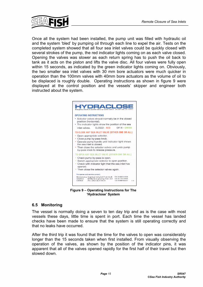
Once all the system had been installed, the pump unit was filled with hydraulic oiland the system ‘bled’ by pumping oil through each line to expel the air. Tests on thecompleted system showed that all four sea inlet valves could be quickly closed withseveral strokes of the pump, the red indicator lights coming on as each valve closed.Opening the valves was slower as each return spring has to push the oil back totank as it acts on the piston and lifts the valve disc. All four valves were fully openwithin 15 seconds, as indicated by the green indicator lights coming on. Obviously,the two smaller sea inlet valves with 30 mm bore actuators were much quicker inoperation than the 100mm valves with 40mm bore actuators as the volume of oil tobe displaced is roughly double. Operating instructions as shown in figure 9 weredisplayed at the control position and the vessels’ skipper and engineer bothinstructed about the system.
6.5 MonitoringThe vessel is normally doing a seven to ten day trip and as is the case with mostvessels these days, little time is spent in port. Each time the vessel has landedchecks have been made to ensure that the system is still operating correctly andthat no leaks have occurred.
After the third trip it was found that the time for the valves to open was considerablylonger than the 15 seconds taken when first installed. From visually observing theoperation of the valves, as shown by the position of the indicator pins, it wasapparent that all of the valves opened rapidly for the first half of their travel but thenslowed down.
Figure 9 – Operating Instructions for The‘Hydraclose’ System

Remote Closure of Sea Inlets
Page 16 SR547©Sea Fish Industry Authority
The two small valves were still opening fully within 15-20 seconds but the two largevalves were just ‘creeping’ the last few mm of travel and it was taking over a minuteto activate the indicator light.
Checks were made and after operating the valves several times the response timedid improve slightly. Considering the situation it was concluded that, as the actuatorseals, both at the piston and the top and bottom glands, settle down there is a slightincrease in drag. Stronger springs seemed the obvious solution to rectify thesituation but fitting such springs would not be possible without lifting the vessel outof the water. Although it was disappointing that the indicator lights were taking a longtime to show green it was not a serious situation because the valves were rapidlyopening for most of their travel and the last few mm would make virtually nodifference to the water flow. The vessel’s engineer was made aware of the situationand the vessel sailed on further trips.
An interim measure, to improve the situation, was to use thinner viscosity oil in thesystem. This returned the response time of 20 seconds but when the opportunityarose to slip the vessel in September, stronger springs were fitted to the 100mmvalve actuators and the system was re-filled with normal hydraulic oil.

Remote Closure of Sea Inlets
Page 17 SR547©Sea Fish Industry Authority
7. DiscussionThe installation of the system on the vessel has resulted in a neat and effectivesystem for emergency closure of the sea inlet valves. The intention of the system isprimarily for the emergency situation but it does offer great convenience in enablingthe routine closure of sea inlets whenever the vessel is unattended. Because anyfailure of the sea inlets could directly affect vessel safety consideration needs to begiven to all possible eventualities.
7.1 Cooling WaterThe most important requirement is that cooling water is always maintained to themain engine and that a failure of the system does not result in the cooling to theengine being lost. This was a key consideration in the design. The adoption of aspring system to hold the inlet valve open, has provided a ‘fail safe’ feature, should aleak occur or a hydraulic pipe become damaged.
7.2 Spring FailureThis is viewed as being very unlikely but not inconceivable. A spring breaking ormore likely weakening would result in the valve not fully opening and the indicatorlight not functioning. Failure of the indicator light should prompt the engineer toinvestigate at the valve and check by the position of the indicator pin if the valve isopen or not. Even if the spring were to break it is still envisaged that the valve wouldbe held open sufficiently to maintain a good water flow.
7.3 Closure of Sea InletsIn an emergency or otherwise, closure can be easily achieved by the hydraulicsystem. Remote operation from the top of the engineroom is the major benefit of thesystem and the power available in the hydraulics will ensure that any ‘stiction’ in thevalve and actuator is overcome.
7.4 Manual OperationThe facility to screw down the valve using the jacking screw makes the manualoperation of the valve the same as that of normal sea inlet valves. Opening the valveis the same action, but it is important to check by observing the indicator pin that thespring has lifted open the valve.
7.5 Indicator Light FailureA positive advantage of the system is the panel of lights to indicate the position ofeach sea inlet valve. Green lights or, red lights, showing, giving confidence and aconstant reminder that the sea inlets are either fully open or closed. Failure of a lightto come on when the system is being operated or the loss of a light at any time willprompt the engineer to go and check at the valve. The neon lights used areextremely reliable and great care has been taken with the micro-switches and wiringto give reliability.

Remote Closure of Sea Inlets
Page 18 SR547©Sea Fish Industry Authority
7.6 Actuator/Valve Stuck in the closed positionShould the actuator piston stick in the bore, creating drag that is greater than theforce of the return spring, then the sea inlet valve could be stuck in the closedposition. Such a situation should not occur if the system is regularly operated but ifunused for a long period ‘stiction’ may occur. Failure of the green indicator light tocome on would make the engineer aware of a possible problem and cause him tocheck at the valve where the position of the indictor pin will show if the valve isclosed or not quite fully open. Manually pulling up on the indicator pin will lift openthe valve.

Remote Closure of Sea Inlets
Page 19 SR547©Sea Fish Industry Authority
8. The Future8.1 CommercialisationThe system will continue to be regularly monitored on the MFV TREASURE. As wasto be expected, lessons have been learnt from the installation, for example, theneed for stronger springs in the larger actuators. However, confidence has nowbeen gained that the system is practical and can be made commercially available.The ‘Hydraclose System’ has been patented by John Buchan and Bill MackieEngineering in Peterhead will install the system on vessels, using actuators suppliedby Darg Engineering. The costs will obviously vary according to the particular vesselbut an indication can be gained from the work carried out on the MFV TREASURE.Installation costs including components such as the pump, manifold etc and theelectrical work was around £3000.
8.2 Industry RequirementsAs was stressed in the introduction, most vessel losses are as a result of flooding,many incidents being caused by failed pipes/fittings in enginerooms. Repeatedly,year after year, crews are faced with a desperate situation of a flooded engineroomand cannot stop the flow of water and yet, in the industry in general, little is done toprevent such occurrences. Sea inlet valves are rarely routinely closed when thevessel is left in port and as a consequence, when they do need to be closeddifficulties can be experienced. The location of sea inlet valves makes theminconvenient to operate and thus, they are forgotten about.
The modern fishing vessel has much technology installed but operates with aminimum of crew. In the past the vessel’s engineer would have made regular visitsto the engineroom to make checks and engage pumps etc. However, virtuallyeverything is now controlled from the wheelhouse resulting in the engineroom beingunchecked for several hours at a time. The sea inlet installations on vessels havebeen improved with the adoption of ‘ring mains’ and screw down valves but theirlocation still results in them being inaccessible. Modern advances, evident in mostother aspects on today’s vessels, now need to be applied to the essentialrequirement of controlling the water entering the vessel.
The Maritime and Coastguard Agency has introduced new regulations as per theCode of Safe Working Practice for the Construction and Use of 15 metre lengthoverall to less than 24 metre registered length Fishing Vessels. This code is to beeffective from 23 November 2002 and will require:
For new vessels:• Each sea inlet valve should be fitted with a positive means of closure from an
accessible position.
• In machinery spaces, controls for main and auxiliary sea inlets essential for theoperation of machinery may be controlled locally. The controls should be readilyaccessible, above the floor plates and be provided with indicators showingwhether the valves are open or closed.

Remote Closure of Sea Inlets
Page 20 SR547©Sea Fish Industry Authority
For existing vessels:• If valves are not fitted above floor plates, rapid and practical means should be
provided to allow for the valve to be operated above floor plate level.
Hence, by regulation, vessel owners will have to ensure that the sea inlet valves ontheir vessels are readily operable. The ‘Hydraclose system’ would seem an excellentmeans to comply with the regulation but more so, it provides convenience, makingthe routine operation of sea inlets so very easy.
8.3 InsurersThe vessel insurers initially meet the high cost of vessel losses but subsequently,the cost is borne by the vessel owners in increased insurance premiums. Anymeasures to combat the risk of vessel losses will benefit the whole industry but mostmeasures require individual vessel owners to invest in improvements on their vessel.To encourage the wide spread adoption of improvements needed to reduce the rateof vessel losses, it is perhaps in the insurers interests to promote measures that willbe effective.

Remote Closure of Sea Inlets
Page 21 SR547©Sea Fish Industry Authority
9. Conclusions• The concept of using hand-powered hydraulics to remotely operate sea inlet
valves has been demonstrated to be quite practical by the installation on theMFV TREASURE. Long term monitoring of the system has yet to be achievedbut confidence has been gained that the system is effective and will close theinlets in an emergency.
• Sea inlet valves should be closed whenever the vessel is to be left unattendedbut the inaccessibility of the sea inlets makes it time consuming and difficult toroutinely carry this out. The convenience offered by a single control position atthe top of the engineroom should encourage the routine operation of thevalves, thereby, ensuring that they do not become seized and can be easilyand quickly closed in an emergency.

Remote Closure of Sea Inlets
Page 22 SR547©Sea Fish Industry Authority
10. AcknowledgementsJohn Buchan’s engineering knowledge and experience plus his determination to seea good idea through has resulted in a very practical and sensible means ofmodernising sea inlet valves to give remote operation. The ‘Hydraclose’ system willbe of benefit to existing vessels and as original equipment on new vessels. Theability to readily operate the sea inlets should result in a significant reduction in thenumbers of vessels that are lost.
Support and encouragement has been particularly given by Bill Taylor of GrampianSea Fishing and Chris Owen, the Skipper of the TREASURE.
Bill Mackie of Bill Mackie Engineering gave the project commercial backing and hasdevoted much time to discussing and developing ideas. Specialist expertise came tothe project when Dennis Duthie of Darg Engineering was brought in to design andmanufacture the actuators.
The Scottish Executive have given essential support to enable the demonstrationinstallation on the TREASURE and interest has been shown by many involved withfishing vessels who have taken the time to come and see the system at the variousstages along its development.
The project is an example of what can be achieved when a good idea is putforward and sensible, practical people work together to make it happen.