Embed Size (px)
Citation preview
Catalog KM-KDS-0119AReplaces document KM-KDS-1017A
QUANTUM AIR
REMOTE AIR COOLED CONDENSERS
GOLD AWARD WINNER
2017 Best New Refrigeration
Product
Quantum Air2
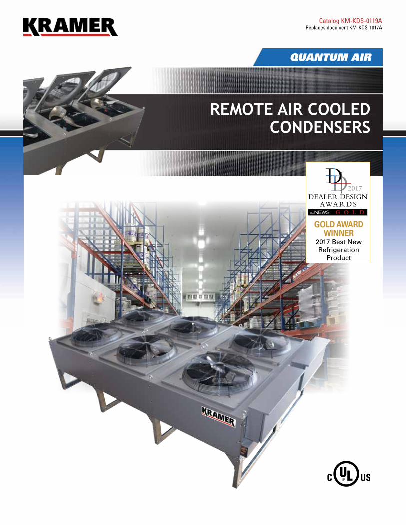
Kramer’s Remote Air Cooled Condensers’ innovative design provides a wide array of solutions focusing on performance, energy efficiency, reduced sound output and other attributes to meet the needs of the grocery, supermarket, industrial cooling and commercial warehousing industries.
Options• Fan cycling head pressure control • Flooded head pressure control• Subcooling circuit• Horizontal air flow• Multi-circuited coils• Wide selection of fin coatings and materials• Individual motor fusing• Individual or paired motor contactors• EMS control options• Variable frequency drives• Multiple control panel locations• Multiple refrigerant options• Thru-the-door fused disconnect• Main circuit breaker disconnect• Leg height up to 46” (18” standard)• Fixed box style legs (25”)
Standard Features• Inverter Duty rail mounted motors• Vertical air flow• Motors with inherent thermal overload protection• 3/8”refrigerant saving copper tube, aluminum fin
coils*• 650 PSIG working pressure• Vinyl coated heavy gauge steel fan guards • Swept wing fan/Venturi improves airflow and sound• Hinged Venturi panels for easy servicing• Hinged leg design for simple installation • Proprietary floating coil• Thru-the-door non-fused disconnect switch• Heavy gauge painted galvanized steel construction • Heavy duty lifting eyes for equipment rigging• UL and cUL listed for outdoor use• LED control panel lighting• California Title 24 compliant - see pages 12-15 and
18-19 for applicable models and details
Efficient and Reliable
* Models with 1 to 4 fans in length have 3/8”copper tubing, which results in using less refrigerant. Models with 5 to 7 fans in length use 1/2” copper tubing.** Capacity at 10 FPI per 1°F TD
Table of Contents Page(s)Features and Options Chart ............................................................................................. 3Highlighted Features Diagrams ........................................................................................ 4Condenser Selection Procedure ....................................................................................... 5-7Performance and Specifications
1140 RPM Models with 1.5 HP Motors ...................................................................... 8-9850 RPM Models with 1.5 HP Motors ....................................................................... 10-11850 RPM Models with 1 HP Motors .......................................................................... 12-13550 RPM Models with 1/3 HP Motors ....................................................................... 14-151200 RPM Models with VSEC Motors ..................................................................... 16-17900 RPM Models with VSEC Motors ......................................................................... 18-19
Head Pressure Control Calculations and Settings ........................................................... 20-21Fan Cycling Control and Fan Speed Control Options ..................................................... 21-22Physical Dimensions and Drawings ................................................................................. 23-24
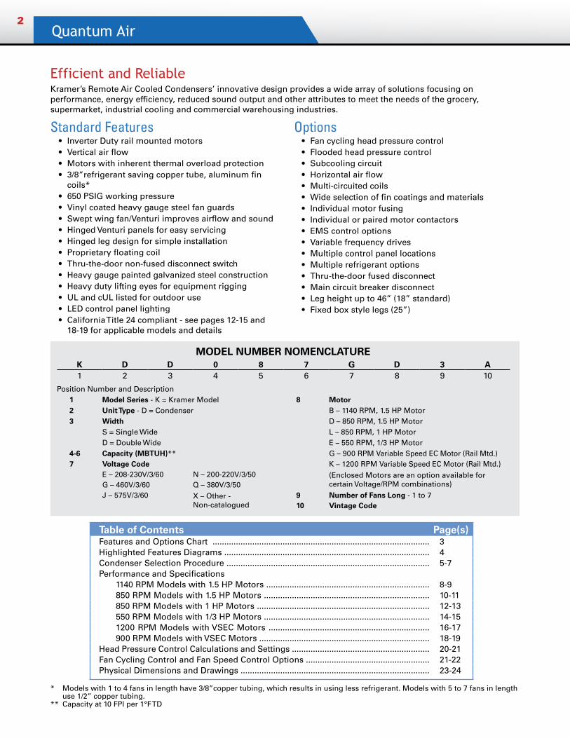
MODEL NUMBER NOMENCLATUREK D D 0 8 7 G D 3 A1 2 3 4 5 6 7 8 9 10
Position Number and Description1 Model Series - K = Kramer Model 8 Motor2 Unit Type - D = Condenser B – 1140 RPM, 1.5 HP Motor3 Width D – 850 RPM, 1.5 HP Motor
S = Single Wide L – 850 RPM, 1 HP MotorD = Double Wide E – 550 RPM, 1/3 HP Motor
4-6 Capacity (MBTUH)** G – 900 RPM Variable Speed EC Motor (Rail Mtd.)7 Voltage Code K – 1200 RPM Variable Speed EC Motor (Rail Mtd.)
E – 208-230V/3/60 N – 200-220V/3/50 (Enclosed Motors are an option available for certain Voltage/RPM combinations)G – 460V/3/60 Q – 380V/3/50
J – 575V/3/60 X – Other - Non-catalogued
9 Number of Fans Long - 1 to 710 Vintage Code
Remote Air Cooled Condensers3
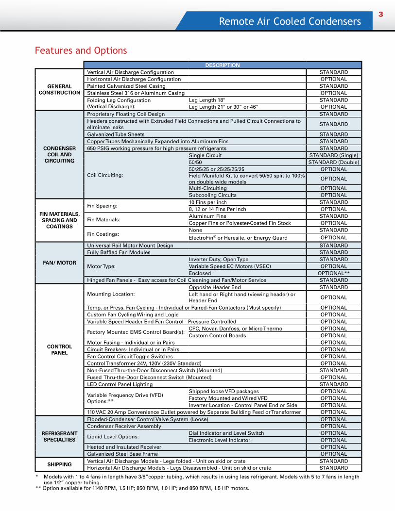
Features and OptionsDESCRIPTION
GENERAL CONSTRUCTION
Vertical Air Discharge Configuration STANDARDHorizontal Air Discharge Configuration OPTIONALPainted Galvanized Steel Casing STANDARDStainless Steel 316 or Aluminum Casing OPTIONALFolding Leg Configuration (Vertical Discharge):
Leg Length 18" STANDARDLeg Length 21" or 30” or 46” OPTIONAL
CONDENSER COIL AND
CIRCUITING
Proprietary Floating Coil Design STANDARD Headers constructed with Extruded Field Connections and Pulled Circuit Connections to eliminate leaks
STANDARD
Galvanized Tube Sheets STANDARDCopper Tubes Mechanically Expanded into Aluminum Fins STANDARD650 PSIG working pressure for high pressure refrigerants STANDARD
Coil Circuiting:
Single Circuit STANDARD (Single)50/50 STANDARD (Double)50/25/25 or 25/25/25/25 OPTIONALField Manifold Kit to convert 50/50 split to 100% on double wide models
OPTIONAL
Multi-Circuiting OPTIONALSubcooling Circuits OPTIONAL
FIN MATERIALS, SPACING AND
COATINGS
Fin Spacing:10 Fins per inch STANDARD8, 12 or 14 Fins Per Inch OPTIONAL
Fin Materials:Aluminum Fins STANDARDCopper Fins or Polyester-Coated Fin Stock OPTIONAL
Fin Coatings:None STANDARD
ElectroFin® or Heresite, or Energy Guard OPTIONAL
FAN/ MOTOR
Universal Rail Motor Mount Design STANDARDFully Baffled Fan Modules STANDARD
Motor Type:Inverter Duty, Open Type STANDARDVariable Speed EC Motors (VSEC) OPTIONALEnclosed OPTIONAL**
Hinged Fan Panels - Easy access for Coil Cleaning and Fan/Motor Service STANDARD
CONTROL PANEL
Mounting Location: Opposite Header End STANDARDLeft hand or Right hand (viewing header) or Header End
OPTIONAL
Temp. or Press. Fan Cycling - Individual or Paired-Fan Contactors (Must specify) OPTIONALCustom Fan Cycling Wiring and Logic OPTIONALVariable Speed Header End Fan Control - Pressure Controlled OPTIONAL
Factory Mounted EMS Control Board(s):CPC, Novar, Danfoss, or Micro Thermo OPTIONALCustom Control Boards OPTIONAL
Motor Fusing - Individual or in Pairs OPTIONALCircuit Breakers- Individual or in Pairs OPTIONALFan Control Circuit Toggle Switches OPTIONALControl Transformer 24V, 120V (230V Standard) OPTIONALNon-Fused Thru-the-Door Disconnect Switch (Mounted) STANDARDFused Thru-the-Door Disconnect Switch (Mounted) OPTIONALLED Control Panel Lighting STANDARD
Variable Frequency Drive (VFD) Options:**
Shipped loose VFD packages OPTIONALFactory Mounted and Wired VFD OPTIONALInverter Location - Control Panel End or Side OPTIONAL
110 VAC 20 Amp Convenience Outlet powered by Separate Building Feed or Transformer OPTIONAL
REFRIGERANT SPECIALTIES
Flooded-Condenser Control Valve System (Loose) OPTIONALCondenser Receiver Assembly OPTIONAL
Liquid Level Options:Dial Indicator and Level Switch OPTIONALElectronic Level Indicator OPTIONAL
Heated and Insulated Receiver OPTIONALGalvanized Steel Base Frame OPTIONAL
SHIPPINGVertical Air Discharge Models - Legs folded - Unit on skid or crate STANDARDHorizontal Air Discharge Models - Legs Disassembled - Unit on skid or crate STANDARD
* Models with 1 to 4 fans in length have 3/8”copper tubing, which results in using less refrigerant. Models with 5 to 7 fans in length use 1/2” copper tubing.** Option available for 1140 RPM, 1.5 HP; 850 RPM, 1.0 HP; and 850 RPM, 1.5 HP motors.
Quantum Air4
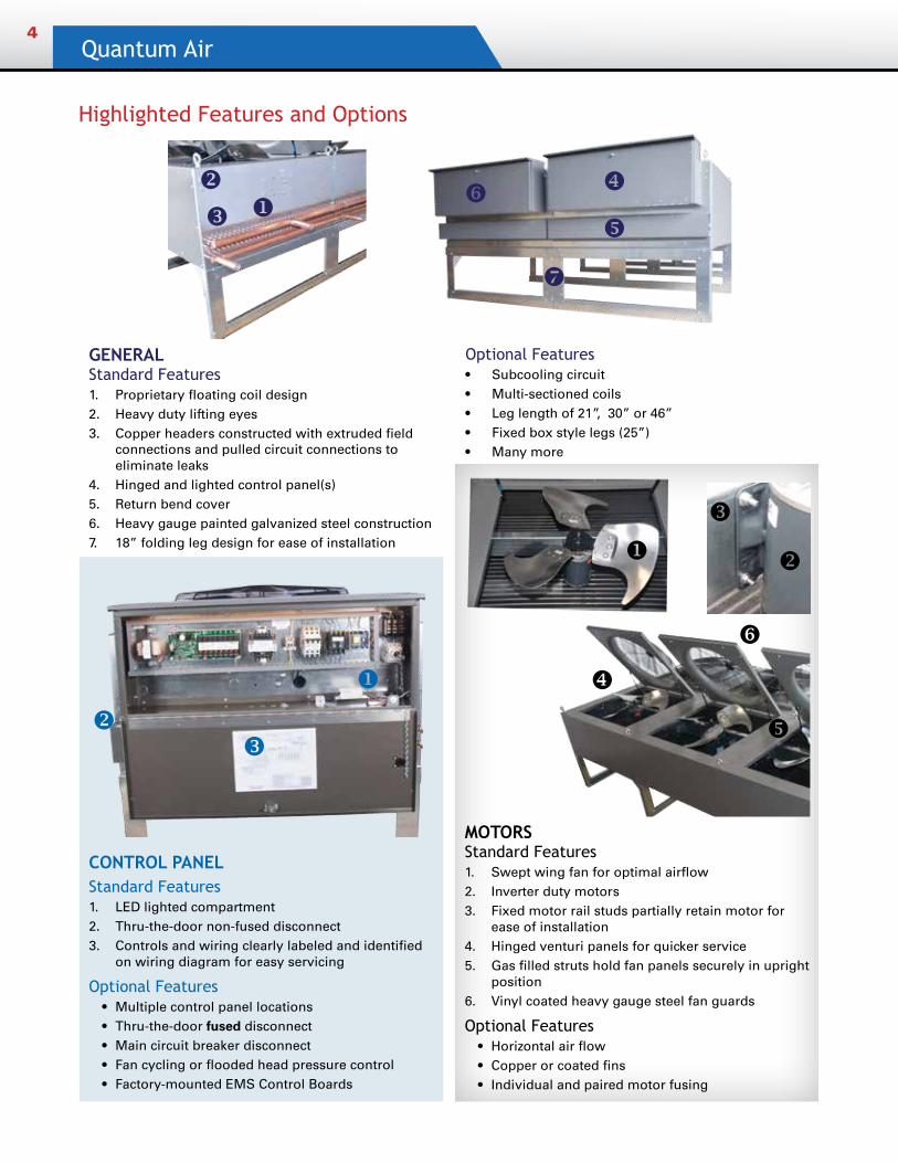
Highlighted Features and Options
GENERAL Standard Features1. Proprietary floating coil design2. Heavy duty lifting eyes3. Copper headers constructed with extruded field
connections and pulled circuit connections to eliminate leaks
4. Hinged and lighted control panel(s)5. Return bend cover6. Heavy gauge painted galvanized steel construction7. 18” folding leg design for ease of installation
CONTROL PANELStandard Features 1. LED lighted compartment2. Thru-the-door non-fused disconnect3. Controls and wiring clearly labeled and identified
on wiring diagram for easy servicing
Optional Features • Multiple control panel locations• Thru-the-door fused disconnect• Main circuit breaker disconnect• Fan cycling or flooded head pressure control• Factory-mounted EMS Control Boards
Optional Features• Subcooling circuit• Multi-sectioned coils• Leg length of 21”, 30” or 46”• Fixed box style legs (25”)• Many more
MOTORS Standard Features1. Swept wing fan for optimal airflow 2. Inverter duty motors3. Fixed motor rail studs partially retain motor for
ease of installation4. Hinged venturi panels for quicker service5. Gas filled struts hold fan panels securely in upright
position6. Vinyl coated heavy gauge steel fan guards
Optional Features• Horizontal air flow• Copper or coated fins• Individual and paired motor fusing
u v
w
x
y
u
vw
uv
w
x
y
z
z
Remote Air Cooled Condensers5
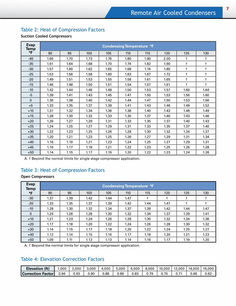
Condenser SelectionAir-cooled condenser capacity ratings are based on the total heat rejection of the refrigeration system. Total heat of rejection is the sum of the compressor capacity and heat of compression added to the refrigerant in the compressor.
The heat of compression varies with the compressor design, so the compressor manufacturer’s information should be used whenever possible. If the compressor manufacturer’s heat of compression information is not available, Tables 2 and 3 (page 7) may be used to determine the heat of compression.
The following formulas may be used to calculate the total heat rejection (THR) for systems that fall outside the normal limits of single stage compressor applications, such as compound or cascade systems.
Suction cooled hermetic compressors: THR = Compressor Capacity (BTUH) + (3413 x KW)
Open Compressors: THR = Compressor Capacity (BTUH) + (2545 x BHP)
ELEVATION CORRECTIONElevation above sea level has an effect on the performance of air cooled condensers. Divide the required capacity by the Elevation Correction Factor in the table on page 7 to correct the requirement to Sea Level Conditions. The proper condenser can then be selected from the appropriate table on Pages 8, 10, 12, 14, 16 or 18.
SINGLE CIRCUIT CONDENSERSAll units are available for single circuit applications. All double fan width units are furnished with dual circuit coils and can be converted in the field for single circuit installations.
SELECTION EXAMPLEGiven:
Ambient Air Temperature = 100° F Design DT = 15° FMidpoint Condensing Temperature* = 115° F Refrigerant = R407AEvaporating Temperature = +20° F Compressor Capacity = 140,000 Compressor Type = Suction Cooled Semi-Hermetic *Refer to Midpoint Selection Graph for explanation
Solution:Multiply the compressor capacity by the heat of compression factor to calculate the required total heat of rejection (THR). Table 1 shows that for 115°F condensing temperature and 20° F evaporator temperature, the heat of compression factor is 1.35. The required total heat rejection (THR) is: 140,000 x 1.35 = 189,000 BTUH THR
Divide the system THR by the condenser delta T (Midpoint Temperature-Ambient Air) = 189,000 ÷ 15 = 12,600 BTUH per 1°F TD
Convert BTUH to MBH = 12,600 BTUH ÷ 1,000 = 12.6 MBH per 1°F TD
The correct selection of a single fan width unit with 850 RPM 1 HP fans and 10 FPI is a model KDS015^L2 with a capacity of 15.1 MBH.
Since the unit selection will almost never have the exact required capacity, the actual TD will vary slightly from the design TD. The actual TD can be calculated using the following formula:
Actual TD = x Design TD
For this example the actual TD would be:Actual TD = x 15 = 12.5°F TD
Design THRActual Condenser THR
12.615.1
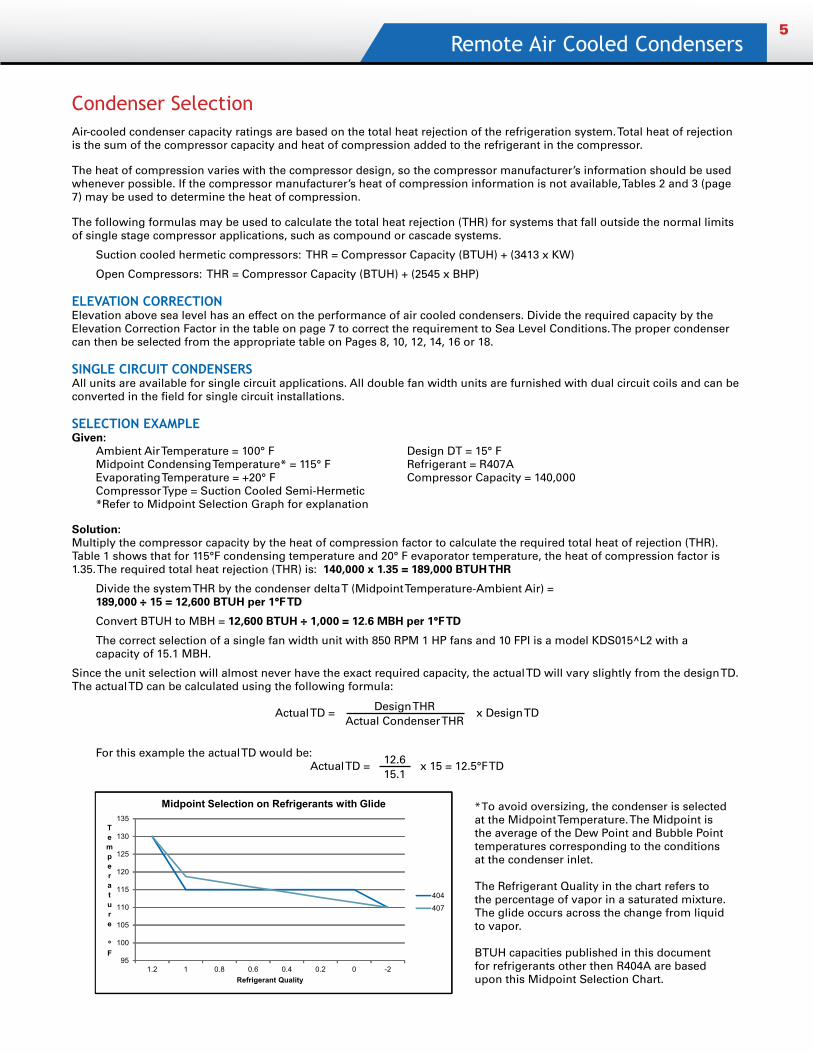
* To avoid oversizing, the condenser is selected at the Midpoint Temperature. The Midpoint is the average of the Dew Point and Bubble Point temperatures corresponding to the conditions at the condenser inlet.
The Refrigerant Quality in the chart refers to the percentage of vapor in a saturated mixture. The glide occurs across the change from liquid to vapor.
BTUH capacities published in this document for refrigerants other then R404A are based upon this Midpoint Selection Chart.
95
100
105
110
115
120
125
130
135
1.2 1 0.8 0.6 0.4 0.2 0 -2
Temperature
ºF
Refrigerant Quality
Midpoint Selection on Refrigerants with Glide
404
407
Quantum Air6
Air-cooled condensers are available for applications where multiple refrigeration systems are connected to the same condenser. Multi-Circuiting is covered in this section.
The condenser coil is divided into the proper number of circuits and each circuit is supplied with an inlet and outlet connection. Each circuit is tagged at the factory for identification. When ordering, the circuits must be placed on the purchase order in numerical sequence. The circuits will be arranged in sequence with the number one section being on the left end when facing the header end of the unit.
EXAMPLE: MULTI-CIRCUITED CONDENSER SELECTION
Given:Refer to Table 1, the Multi-Circuit Calculation Form below. Four suction cooled semi-hermetic compressors are shown with their operating conditions. Design ambient temperature is 95° F.
Procedure:1. Complete the customer data in columns 1 through 6 in Table 1.
2. Fill in the heat of compression factors in column 7. If the compressor manufacturer’s data is not available, use values from tables 2 and 3.
3. Multiply the values in column 6 by the values in column 7 and tabulate the results in column 8.
4. Next, divide the heat rejection values in column 8 by the design TD values in column 3 and enter the results in column 9.
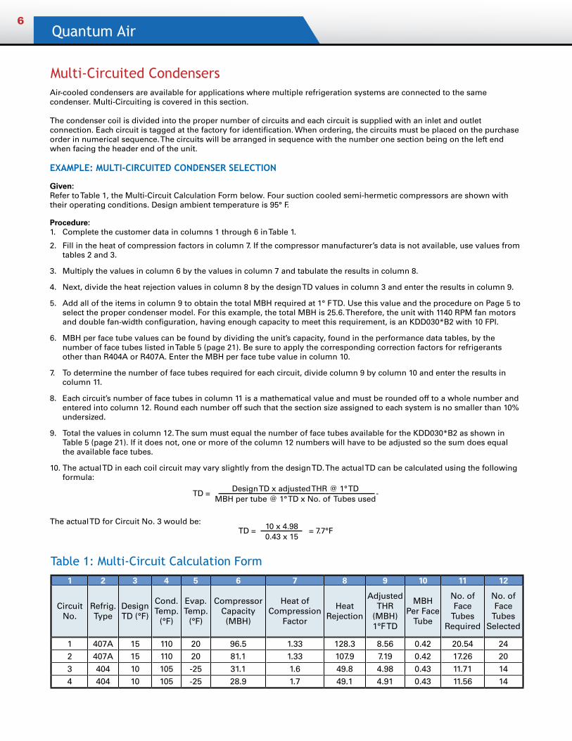
5. Add all of the items in column 9 to obtain the total MBH required at 1° F TD. Use this value and the procedure on Page 5 to select the proper condenser model. For this example, the total MBH is 25.6. Therefore, the unit with 1140 RPM fan motors and double fan-width configuration, having enough capacity to meet this requirement, is an KDD030*B2 with 10 FPI.
6. MBH per face tube values can be found by dividing the unit’s capacity, found in the performance data tables, by the number of face tubes listed in Table 5 (page 21). Be sure to apply the corresponding correction factors for refrigerants other than R404A or R407A. Enter the MBH per face tube value in column 10.
7. To determine the number of face tubes required for each circuit, divide column 9 by column 10 and enter the results in column 11.
8. Each circuit’s number of face tubes in column 11 is a mathematical value and must be rounded off to a whole number and entered into column 12. Round each number off such that the section size assigned to each system is no smaller than 10% undersized.
9. Total the values in column 12. The sum must equal the number of face tubes available for the KDD030*B2 as shown in Table 5 (page 21). If it does not, one or more of the column 12 numbers will have to be adjusted so the sum does equal the available face tubes.
10. The actual TD in each coil circuit may vary slightly from the design TD. The actual TD can be calculated using the following formula:
TD = -
The actual TD for Circuit No. 3 would be:TD = = 7.7°F
Multi-Circuited Condensers
Table 1: Multi-Circuit Calculation Form
Design TD x adjusted THR @ 1° TDMBH per tube @ 1° TD x No. of Tubes used
10 x 4.980.43 x 15
1 2 3 4 5 6 7 8 9 10 11 12
Circuit No.
Refrig. Type
Design TD (°F)
Cond. Temp.
(°F)
Evap. Temp.
(°F)
Compressor Capacity (MBH)
Heat of Compression
Factor
Heat Rejection
Adjusted THR
(MBH) 1°F TD
MBH Per Face
Tube
No. of Face
Tubes Required
No. of Face
Tubes Selected
1 407A 15 110 20 96.5 1.33 128.3 8.56 0.42 20.54 242 407A 15 110 20 81.1 1.33 107.9 7.19 0.42 17.26 20
3 404 10 105 -25 31.1 1.6 49.8 4.98 0.43 11.71 144 404 10 105 -25 28.9 1.7 49.1 4.91 0.43 11.56 14
Remote Air Cooled Condensers7
EvapTemp
°F
Condensing Temperature °F
90 95 100 105 110 115 120 125 130
-40 1.66 1.70 1.73 1.76 1.80 1.90 2.00 † †-35 1.61 1.64 1.68 1.70 1.74 1.82 1.90 † †
-30 1.57 1.60 1.62 1.65 1.68 1.74 1.80 † †
-25 1.53 1.56 1.58 1.60 1.63 1.67 1.72 † †
-20 1.49 1.51 1.53 1.55 1.58 1.61 1.65 † †
-15 1.46 1.48 1.50 1.51 1.54 1.57 1.61 † †
-10 1.42 1.44 1.46 1.48 1.50 1.53 1.57 1.60 1.64
-5 1.39 1.41 1.43 1.45 1.47 1.50 1.53 1.56 1.60
0 1.36 1.38 1.40 1.42 1.44 1.47 1.50 1.53 1.56
+5 1.33 1.35 1.37 1.39 1.41 1.43 1.46 1.49 1.52
+10 1.31 1.32 1.34 1.36 1.38 1.40 1.43 1.46 1.49
+15 1.28 1.30 1.32 1.33 1.35 1.37 1.40 1.43 1.46
+20 1.26 1.27 1.29 1.31 1.33 1.35 1.37 1.40 1.43
+25 1.24 1.25 1.27 1.29 1.31 1.33 1.35 1.37 1.40
+30 1.22 1.23 1.25 1.26 1.28 1.30 1.32 1.34 1.37
+35 1.20 1.21 1.23 1.25 1.26 1.27 1.29 1.31 1.34
+40 1.18 1.19 1.21 1.23 1.24 1.25 1.27 1.29 1.31
+45 1.16 1.17 1.19 1.21 1.22 1.23 1.25 1.26 1.28+50 1.14 1.15 1.17 1.19 1.20 1.22 1.23 1.24 1.26
Table 2: Heat of Compression FactorsSuction Cooled Compressors
A. † Beyond the normal limits for single stage compressor application.
Table 3: Heat of Compression FactorsOpen Compressors
Evap Temp
°F
Condensing Temperature °F
90 95 100 105 110 115 120 125 130
-30 1.37 1.39 1.42 1.44 1.47 † † † †-20 1.33 1.35 1.37 1.39 1.42 1.44 1.47 † †
-10 1.28 1.30 1.32 1.34 1.37 1.39 1.42 1.44 1.470 1.24 1.26 1.28 1.30 1.32 1.34 1.37 1.39 1.41
+10 1.21 1.23 1.24 1.26 1.28 1.30 1.32 1.34 1.36
+20 1.17 1.18 1.20 1.22 1.24 1.26 1.28 1.30 1.32
+30 1.14 1.15 1.17 1.18 1.20 1.22 1.24 1.25 1.27
+40 1.12 1.14 1.15 1.16 1.17 1.18 1.20 1.21 1.23+50 1.09 1.11 1.12 1.13 1.14 1.16 1.17 1.19 1.20
A. † Beyond the normal limits for single stage compressor application.
Table 4: Elevation Correction Factors
Elevation (ft) 1,000 2,000 3,000 4,000 5,000 6,000 8,000 10,000 12,000 14,000 16,000
Correction Factor 0.94 0.93 0.90 0.88 0.86 0.83 0.79 0.75 0.71 0.66 0.62
Quantum Air8
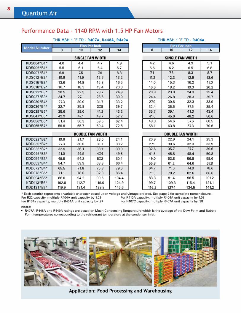
Performance Data - 1140 RPM with 1.5 HP Fan Motors
* Each asterisk represents a variable character based upon voltage and vintage ordered. See page 2 for complete nomenclature.For R22 capacity, multiply R404A unit capacity by 1.02 For R410A capacity, multiply R404A unit capacity by 1.08 For R134a capacity, multiply R404A unit capacity by .97 For R407C capacity, multiply R407A unit capacity by .98
Notes: • R407A, R448A and R449A ratings are based on Mean Condensing Temperature which is the average of the Dew Point and Bubble
Point temperatures corresponding to the refrigerant temperature at the condenser inlet.
THR MBH 1°F TD - R407A, R448A, R449A THR MBH 1°F TD - R404A
Model Number Fins Per Inch Fins Per Inch8 10 12 14 8 10 12 14
SINGLE FAN WIDTH SINGLE FAN WIDTHKDS004*B1* 4.0 4.4 4.7 4.9 4.2 4.6 4.9 5.1KDS006*B1* 5.5 6.1 6.4 6.7 5.6 6.2 6.5 6.8KDS007*B1* 6.9 7.5 7.9 8.3 7.1 7.8 8.3 8.7KDS012*B2* 10.9 11.9 12.6 13.2 11.2 12.3 12.9 13.6KDS015*B2* 13.6 14.9 15.8 16.5 14.0 15.3 16.2 17.0KDS018*B2* 16.7 18.3 19.4 20.3 16.6 18.2 19.3 20.2KDS022*B3* 20.5 22.5 23.7 24.9 20.9 23.0 24.3 25.4KDS027*B3* 24.7 27.1 28.6 30.0 24.4 26.8 28.3 29.7KDS030*B4* 27.3 30.0 31.7 33.2 27.9 30.6 32.3 33.9KDS036*B4* 32.7 35.8 37.9 39.7 32.4 35.5 37.5 39.4KDS039*B5* 35.6 39.0 41.2 43.3 35.7 39.1 41.3 43.4KDS047*B5* 42.9 47.1 49.7 52.2 41.6 45.6 48.2 50.6KDS056*B6* 51.4 56.3 59.5 62.4 49.8 54.6 57.6 60.5KDS065*B7* 59.9 65.7 69.4 72.8 58.1 63.8 67.3 70.6
DOUBLE FAN WIDTH DOUBLE FAN WIDTHKDD022*B2* 19.8 21.7 23.0 24.1 20.9 22.9 24.1 25.3KDD030*B2* 27.3 30.0 31.7 33.2 27.9 30.6 32.3 33.9KDD036*B2* 32.9 36.1 38.1 39.9 32.6 35.7 37.7 39.6KDD045*B3* 41.0 44.9 47.4 49.8 41.8 45.8 48.4 50.8KDD054*B3* 49.5 54.3 57.3 60.1 49.0 53.8 56.8 59.6KDD059*B4* 54.7 59.9 63.3 66.4 55.8 61.2 64.6 67.8KDD072*B4* 65.5 71.8 75.8 79.5 64.7 71.0 74.9 78.6KDD078*B5* 71.1 78.0 82.3 86.4 71.3 78.2 82.6 86.6KDD094*B5* 86.0 94.2 99.5 104.4 83.3 91.4 96.5 101.2KDD113*B6* 102.8 112.7 119.0 124.9 99.7 109.3 115.4 121.1KDD131*B7* 119.9 131.4 138.8 145.6 116.2 127.4 134.5 141.2
Application: Food Processing and Warehousing
Remote Air Cooled Condensers9
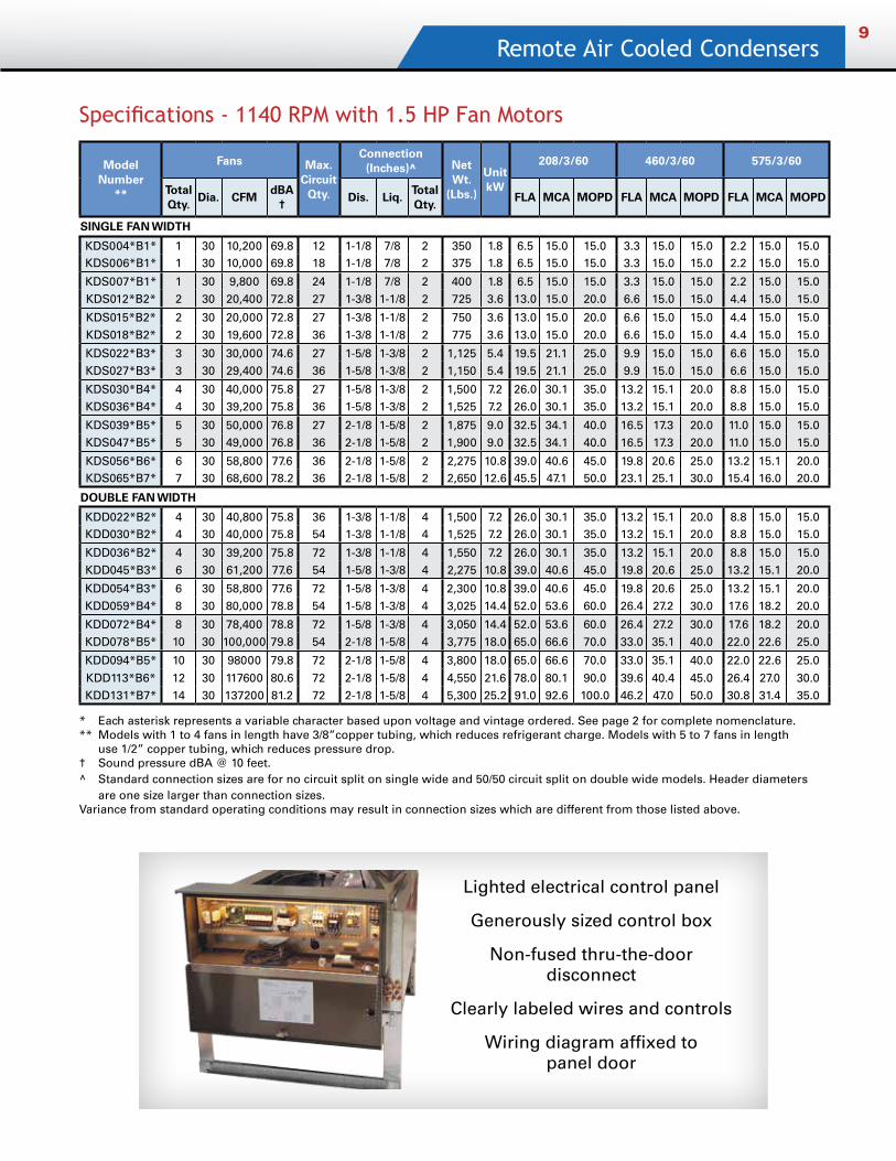
Specifications - 1140 RPM with 1.5 HP Fan Motors
* Each asterisk represents a variable character based upon voltage and vintage ordered. See page 2 for complete nomenclature.** Models with 1 to 4 fans in length have 3/8”copper tubing, which reduces refrigerant charge. Models with 5 to 7 fans in length use 1/2” copper tubing, which reduces pressure drop.† Sound pressure dBA @ 10 feet.^ Standard connection sizes are for no circuit split on single wide and 50/50 circuit split on double wide models. Header diameters are one size larger than connection sizes.Variance from standard operating conditions may result in connection sizes which are different from those listed above.
Lighted electrical control panel
Generously sized control box
Non-fused thru-the-door disconnect
Clearly labeled wires and controls
Wiring diagram affixed to panel door
Model Number
**
Fans Max. Circuit
Qty.
Connection (Inches)^ Net
Wt. (Lbs.)
Unit kW
208/3/60 460/3/60 575/3/60
Total Qty.
Dia. CFMdBA
† Dis. Liq.
Total Qty.
FLA MCA MOPD FLA MCA MOPD FLA MCA MOPD
SINGLE FAN WIDTH
KDS004*B1* 1 30 10,200 69.8 12 1-1/8 7/8 2 350 1.8 6.5 15.0 15.0 3.3 15.0 15.0 2.2 15.0 15.0KDS006*B1* 1 30 10,000 69.8 18 1-1/8 7/8 2 375 1.8 6.5 15.0 15.0 3.3 15.0 15.0 2.2 15.0 15.0
KDS007*B1* 1 30 9,800 69.8 24 1-1/8 7/8 2 400 1.8 6.5 15.0 15.0 3.3 15.0 15.0 2.2 15.0 15.0KDS012*B2* 2 30 20,400 72.8 27 1-3/8 1-1/8 2 725 3.6 13.0 15.0 20.0 6.6 15.0 15.0 4.4 15.0 15.0
KDS015*B2* 2 30 20,000 72.8 27 1-3/8 1-1/8 2 750 3.6 13.0 15.0 20.0 6.6 15.0 15.0 4.4 15.0 15.0KDS018*B2* 2 30 19,600 72.8 36 1-3/8 1-1/8 2 775 3.6 13.0 15.0 20.0 6.6 15.0 15.0 4.4 15.0 15.0
KDS022*B3* 3 30 30,000 74.6 27 1-5/8 1-3/8 2 1,125 5.4 19.5 21.1 25.0 9.9 15.0 15.0 6.6 15.0 15.0KDS027*B3* 3 30 29,400 74.6 36 1-5/8 1-3/8 2 1,150 5.4 19.5 21.1 25.0 9.9 15.0 15.0 6.6 15.0 15.0
KDS030*B4* 4 30 40,000 75.8 27 1-5/8 1-3/8 2 1,500 7.2 26.0 30.1 35.0 13.2 15.1 20.0 8.8 15.0 15.0KDS036*B4* 4 30 39,200 75.8 36 1-5/8 1-3/8 2 1,525 7.2 26.0 30.1 35.0 13.2 15.1 20.0 8.8 15.0 15.0
KDS039*B5* 5 30 50,000 76.8 27 2-1/8 1-5/8 2 1,875 9.0 32.5 34.1 40.0 16.5 17.3 20.0 11.0 15.0 15.0KDS047*B5* 5 30 49,000 76.8 36 2-1/8 1-5/8 2 1,900 9.0 32.5 34.1 40.0 16.5 17.3 20.0 11.0 15.0 15.0
KDS056*B6* 6 30 58,800 77.6 36 2-1/8 1-5/8 2 2,275 10.8 39.0 40.6 45.0 19.8 20.6 25.0 13.2 15.1 20.0KDS065*B7* 7 30 68,600 78.2 36 2-1/8 1-5/8 2 2,650 12.6 45.5 47.1 50.0 23.1 25.1 30.0 15.4 16.0 20.0
DOUBLE FAN WIDTH
KDD022*B2* 4 30 40,800 75.8 36 1-3/8 1-1/8 4 1,500 7.2 26.0 30.1 35.0 13.2 15.1 20.0 8.8 15.0 15.0KDD030*B2* 4 30 40,000 75.8 54 1-3/8 1-1/8 4 1,525 7.2 26.0 30.1 35.0 13.2 15.1 20.0 8.8 15.0 15.0
KDD036*B2* 4 30 39,200 75.8 72 1-3/8 1-1/8 4 1,550 7.2 26.0 30.1 35.0 13.2 15.1 20.0 8.8 15.0 15.0KDD045*B3* 6 30 61,200 77.6 54 1-5/8 1-3/8 4 2,275 10.8 39.0 40.6 45.0 19.8 20.6 25.0 13.2 15.1 20.0
KDD054*B3* 6 30 58,800 77.6 72 1-5/8 1-3/8 4 2,300 10.8 39.0 40.6 45.0 19.8 20.6 25.0 13.2 15.1 20.0KDD059*B4* 8 30 80,000 78.8 54 1-5/8 1-3/8 4 3,025 14.4 52.0 53.6 60.0 26.4 27.2 30.0 17.6 18.2 20.0
KDD072*B4* 8 30 78,400 78.8 72 1-5/8 1-3/8 4 3,050 14.4 52.0 53.6 60.0 26.4 27.2 30.0 17.6 18.2 20.0KDD078*B5* 10 30 100,000 79.8 54 2-1/8 1-5/8 4 3,775 18.0 65.0 66.6 70.0 33.0 35.1 40.0 22.0 22.6 25.0
KDD094*B5* 10 30 98000 79.8 72 2-1/8 1-5/8 4 3,800 18.0 65.0 66.6 70.0 33.0 35.1 40.0 22.0 22.6 25.0
KDD113*B6* 12 30 117600 80.6 72 2-1/8 1-5/8 4 4,550 21.6 78.0 80.1 90.0 39.6 40.4 45.0 26.4 27.0 30.0KDD131*B7* 14 30 137200 81.2 72 2-1/8 1-5/8 4 5,300 25.2 91.0 92.6 100.0 46.2 47.0 50.0 30.8 31.4 35.0

Quantum Air10
Performance Data - 850 RPM with 1.5 HP Fan MotorsTHR MBH 1°F TD - R407A, R448A, R449A THR MBH 1°F TD - R404A
Model NumberFins Per Inch Fins Per Inch
8 10 12 14 8 10 12 14
SINGLE FAN WIDTH SINGLE FAN WIDTHKDS004*D1* 3.3 3.6 3.8 4.0 3.7 4.0 4.3 4.7KDS005*D1* 4.7 5.2 5.4 5.7 5.1 5.6 5.9 6.5KDS007*D1* 5.9 6.5 6.8 7.1 6.3 6.9 7.3 8.0KDS010*D2* 9.0 9.9 10.5 10.9 9.5 10.4 11.0 12.1KDS014*D2* 12.6 13.8 14.6 15.2 12.8 14.0 14.8 16.3KDS015*D2* 13.9 15.3 16.1 16.8 14.3 15.7 16.5 18.2KDS021*D3* 19.1 20.9 22.1 23.0 19.3 21.2 22.4 24.6KDS024*D3* 22.3 24.4 25.8 26.9 21.9 24.0 25.4 27.9KDS028*D4* 25.2 27.7 29.2 30.4 25.7 28.2 29.8 32.7KDS032*D4* 29.4 32.2 34.0 35.4 28.9 31.7 33.5 36.8KDS035*D5* 31.5 34.5 36.5 38.0 31.4 34.4 36.4 40.0KDS043*D5* 39.3 43.1 45.5 47.4 37.9 41.5 43.8 48.2KDS052*D6* 47.2 51.7 54.6 56.9 45.4 49.8 52.6 57.8KDS060*D7* 55.0 60.3 63.7 66.3 53.1 58.2 61.4 67.6
DOUBLE FAN WIDTH DOUBLE FAN WIDTHKDD019*D2* 17.5 19.2 20.3 21.1 18.4 20.2 21.3 23.5KDD028*D2* 25.2 27.7 29.2 30.4 25.6 28.1 29.7 32.6KDD031*D2* 28.6 31.3 33.1 34.4 28.1 30.8 32.5 35.8KDD041*D3* 37.5 41.1 43.4 45.2 38.0 41.7 44.0 48.5KDD048*D3* 44.1 48.4 51.1 53.2 43.4 47.6 50.2 55.3KDD055*D4* 50.6 55.4 58.6 61.0 51.4 56.4 59.5 65.5KDD065*D4* 58.9 64.5 68.2 71.0 57.8 63.4 67.0 73.7KDD069*D5* 63.0 69.1 73.0 76.0 62.9 69.0 72.8 80.1KDD086*D5* 78.6 86.2 91.0 94.8 75.8 83.1 87.8 96.6KDD103*D6* 94.2 103.3 109.1 113.7 90.9 99.7 105.3 115.8KDD121*D7* 110.0 120.6 127.3 132.7 106.0 116.3 122.8 135.0
* Each asterisk represents a variable character based upon voltage and vintage ordered. See page 2 for complete nomenclature.For R22 capacity, multiply R404A unit capacity by 1.02 For R410A capacity, multiply R404A unit capacity by 1.08 For R134a capacity, multiply R404A unit capacity by .97 For R407C capacity, multiply R407A unit capacity by .98
Notes: • R407A, R448A and R449A ratings are based on Mean Condensing Temperature which is the average of the Dew Point and Bubble
Point temperatures corresponding to the refrigerant temperature at the condenser inlet.
Remote Air Cooled Condensers11
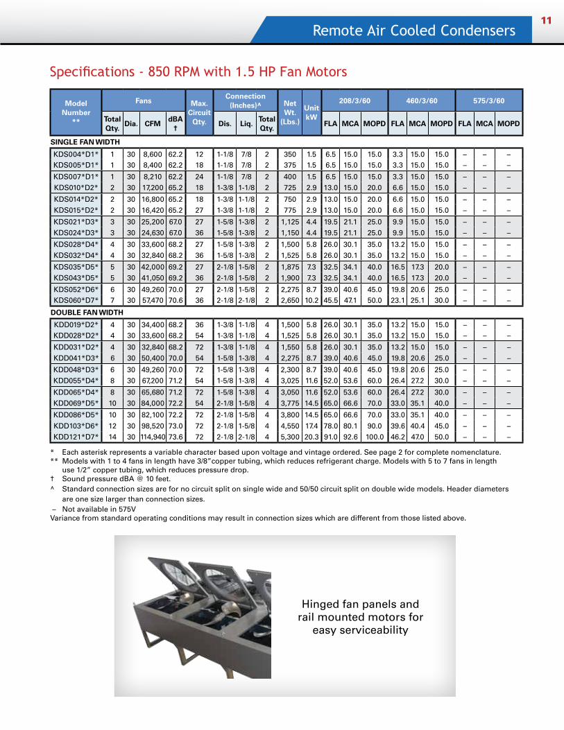
Specifications - 850 RPM with 1.5 HP Fan Motors
* Each asterisk represents a variable character based upon voltage and vintage ordered. See page 2 for complete nomenclature.** Models with 1 to 4 fans in length have 3/8”copper tubing, which reduces refrigerant charge. Models with 5 to 7 fans in length use 1/2” copper tubing, which reduces pressure drop.† Sound pressure dBA @ 10 feet.^ Standard connection sizes are for no circuit split on single wide and 50/50 circuit split on double wide models. Header diameters are one size larger than connection sizes. – Not available in 575VVariance from standard operating conditions may result in connection sizes which are different from those listed above.
Model Number
**
Fans Max. Circuit
Qty.
Connection (Inches)^ Net
Wt. (Lbs.)
Unit kW
208/3/60 460/3/60 575/3/60
Total Qty.
Dia. CFMdBA
†Dis. Liq.
Total Qty.
FLA MCA MOPD FLA MCA MOPD FLA MCA MOPD
SINGLE FAN WIDTH
KDS004*D1* 1 30 8,600 62.2 12 1-1/8 7/8 2 350 1.5 6.5 15.0 15.0 3.3 15.0 15.0 – – –KDS005*D1* 1 30 8,400 62.2 18 1-1/8 7/8 2 375 1.5 6.5 15.0 15.0 3.3 15.0 15.0 – – –
KDS007*D1* 1 30 8,210 62.2 24 1-1/8 7/8 2 400 1.5 6.5 15.0 15.0 3.3 15.0 15.0 – – –KDS010*D2* 2 30 17,200 65.2 18 1-3/8 1-1/8 2 725 2.9 13.0 15.0 20.0 6.6 15.0 15.0 – – –
KDS014*D2* 2 30 16,800 65.2 18 1-3/8 1-1/8 2 750 2.9 13.0 15.0 20.0 6.6 15.0 15.0 – – –KDS015*D2* 2 30 16,420 65.2 27 1-3/8 1-1/8 2 775 2.9 13.0 15.0 20.0 6.6 15.0 15.0 – – –
KDS021*D3* 3 30 25,200 67.0 27 1-5/8 1-3/8 2 1,125 4.4 19.5 21.1 25.0 9.9 15.0 15.0 – – –KDS024*D3* 3 30 24,630 67.0 36 1-5/8 1-3/8 2 1,150 4.4 19.5 21.1 25.0 9.9 15.0 15.0 – – –
KDS028*D4* 4 30 33,600 68.2 27 1-5/8 1-3/8 2 1,500 5.8 26.0 30.1 35.0 13.2 15.0 15.0 – – –KDS032*D4* 4 30 32,840 68.2 36 1-5/8 1-3/8 2 1,525 5.8 26.0 30.1 35.0 13.2 15.0 15.0 – – –
KDS035*D5* 5 30 42,000 69.2 27 2-1/8 1-5/8 2 1,875 7.3 32.5 34.1 40.0 16.5 17.3 20.0 – – –KDS043*D5* 5 30 41,050 69.2 36 2-1/8 1-5/8 2 1,900 7.3 32.5 34.1 40.0 16.5 17.3 20.0 – – –
KDS052*D6* 6 30 49,260 70.0 27 2-1/8 1-5/8 2 2,275 8.7 39.0 40.6 45.0 19.8 20.6 25.0 – – –KDS060*D7* 7 30 57,470 70.6 36 2-1/8 2-1/8 2 2,650 10.2 45.5 47.1 50.0 23.1 25.1 30.0 – – –
DOUBLE FAN WIDTH
KDD019*D2* 4 30 34,400 68.2 36 1-3/8 1-1/8 4 1,500 5.8 26.0 30.1 35.0 13.2 15.0 15.0 – – –KDD028*D2* 4 30 33,600 68.2 54 1-3/8 1-1/8 4 1,525 5.8 26.0 30.1 35.0 13.2 15.0 15.0 – – –
KDD031*D2* 4 30 32,840 68.2 72 1-3/8 1-1/8 4 1,550 5.8 26.0 30.1 35.0 13.2 15.0 15.0 – – –KDD041*D3* 6 30 50,400 70.0 54 1-5/8 1-3/8 4 2,275 8.7 39.0 40.6 45.0 19.8 20.6 25.0 – – –
KDD048*D3* 6 30 49,260 70.0 72 1-5/8 1-3/8 4 2,300 8.7 39.0 40.6 45.0 19.8 20.6 25.0 – – –KDD055*D4* 8 30 67,200 71.2 54 1-5/8 1-3/8 4 3,025 11.6 52.0 53.6 60.0 26.4 27.2 30.0 – – –
KDD065*D4* 8 30 65,680 71.2 72 1-5/8 1-3/8 4 3,050 11.6 52.0 53.6 60.0 26.4 27.2 30.0 – – –KDD069*D5* 10 30 84,000 72.2 54 2-1/8 1-5/8 4 3,775 14.5 65.0 66.6 70.0 33.0 35.1 40.0 – – –
KDD086*D5* 10 30 82,100 72.2 72 2-1/8 1-5/8 4 3,800 14.5 65.0 66.6 70.0 33.0 35.1 40.0 – – –
KDD103*D6* 12 30 98,520 73.0 72 2-1/8 1-5/8 4 4,550 17.4 78.0 80.1 90.0 39.6 40.4 45.0 – – –KDD121*D7* 14 30 114,940 73.6 72 2-1/8 2-1/8 4 5,300 20.3 91.0 92.6 100.0 46.2 47.0 50.0 – – –
Hinged fan panels and rail mounted motors for
easy serviceability
Quantum Air12
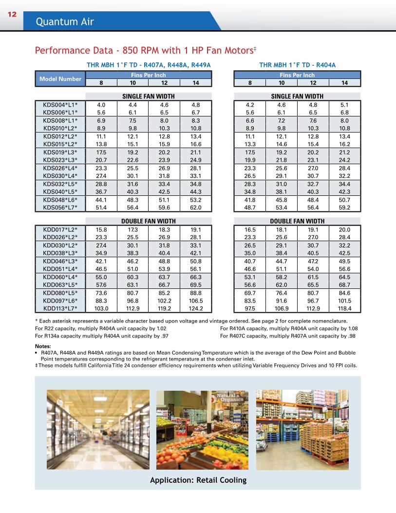
Performance Data - 850 RPM with 1 HP Fan Motors‡
THR MBH 1°F TD - R407A, R448A, R449A THR MBH 1°F TD - R404A
Model NumberFins Per Inch Fins Per Inch
8 10 12 14 8 10 12 14
SINGLE FAN WIDTH SINGLE FAN WIDTHKDS004*L1* 4.0 4.4 4.6 4.8 4.2 4.6 4.8 5.1KDS006*L1* 5.6 6.1 6.5 6.7 5.6 6.1 6.5 6.8KDS008*L1* 6.9 7.5 8.0 8.3 6.6 7.2 7.6 8.0KDS010*L2* 8.9 9.8 10.3 10.8 8.9 9.8 10.3 10.8KDS012*L2* 11.1 12.1 12.8 13.4 11.1 12.1 12.8 13.4KDS015*L2* 13.8 15.1 15.9 16.6 13.3 14.6 15.4 16.2KDS019*L3* 17.5 19.2 20.2 21.1 17.5 19.2 20.2 21.2KDS023*L3* 20.7 22.6 23.9 24.9 19.9 21.8 23.1 24.2KDS026*L4* 23.3 25.5 26.9 28.1 23.3 25.6 27.0 28.4KDS030*L4* 27.4 30.1 31.8 33.1 26.5 29.1 30.7 32.2KDS032*L5* 28.8 31.6 33.4 34.8 28.3 31.0 32.7 34.4KDS040*L5* 36.7 40.3 42.5 44.3 34.8 38.1 40.3 42.3KDS048*L6* 44.1 48.3 51.1 53.2 41.8 45.8 48.4 50.7KDS056*L7* 51.4 56.4 59.6 62.0 48.7 53.4 56.4 59.2
DOUBLE FAN WIDTH DOUBLE FAN WIDTHKDD017*L2* 15.8 17.3 18.3 19.1 16.5 18.1 19.1 20.0KDD026*L2* 23.3 25.5 26.9 28.1 23.3 25.6 27.0 28.4KDD030*L2* 27.4 30.1 31.8 33.1 26.5 29.1 30.7 32.2KDD038*L3* 34.9 38.3 40.4 42.1 35.0 38.4 40.5 42.5KDD046*L3* 42.1 46.2 48.8 50.8 40.7 44.7 47.2 49.5KDD051*L4* 46.5 51.0 53.9 56.1 46.6 51.1 54.0 56.6KDD060*L4* 55.0 60.3 63.7 66.3 53.1 58.2 61.5 64.5KDD063*L5* 57.6 63.1 66.7 69.5 56.6 62.0 65.5 68.7KDD080*L5* 73.6 80.7 85.2 88.8 69.7 76.4 80.7 84.6KDD097*L6* 88.3 96.8 102.2 106.5 83.5 91.6 96.7 101.5KDD113*L7* 103.0 112.9 119.2 124.2 97.5 106.9 112.9 118.4
Application: Retail Cooling
* Each asterisk represents a variable character based upon voltage and vintage ordered. See page 2 for complete nomenclature.For R22 capacity, multiply R404A unit capacity by 1.02 For R410A capacity, multiply R404A unit capacity by 1.08 For R134a capacity multiply R404A unit capacity by .97 For R407C capacity, multiply R407A unit capacity by .98
Notes:• R407A, R448A and R449A ratings are based on Mean Condensing Temperature which is the average of the Dew Point and Bubble
Point temperatures corresponding to the refrigerant temperature at the condenser inlet. ‡ These models fulfill California Title 24 condenser efficiency requirements when utilizing Variable Frequency Drives and 10 FPI coils.
Remote Air Cooled Condensers13
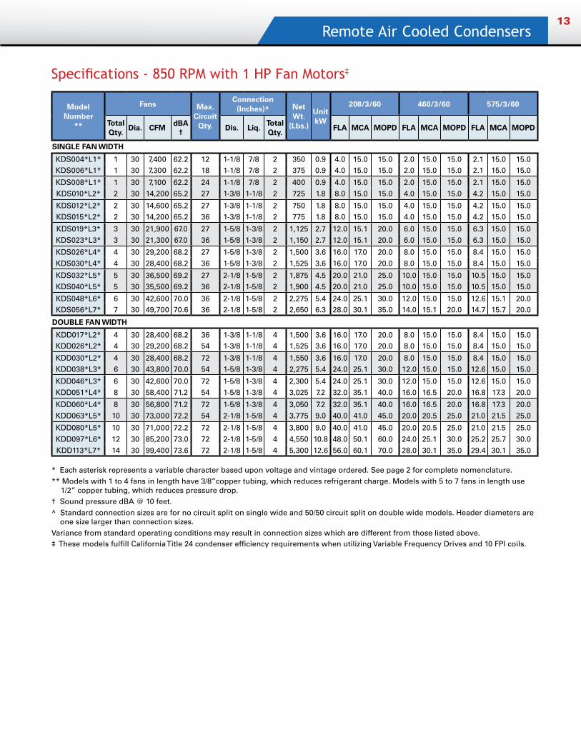
Specifications - 850 RPM with 1 HP Fan Motors‡
Model Number
**
Fans Max. Circuit
Qty.
Connection (Inches)^ Net
Wt. (Lbs.)
Unit kW
208/3/60 460/3/60 575/3/60
Total Qty.
Dia. CFMdBA
†Dis. Liq.
Total Qty.
FLA MCA MOPD FLA MCA MOPD FLA MCA MOPD
SINGLE FAN WIDTH
KDS004*L1* 1 30 7,400 62.2 12 1-1/8 7/8 2 350 0.9 4.0 15.0 15.0 2.0 15.0 15.0 2.1 15.0 15.0KDS006*L1* 1 30 7,300 62.2 18 1-1/8 7/8 2 375 0.9 4.0 15.0 15.0 2.0 15.0 15.0 2.1 15.0 15.0
KDS008*L1* 1 30 7,100 62.2 24 1-1/8 7/8 2 400 0.9 4.0 15.0 15.0 2.0 15.0 15.0 2.1 15.0 15.0KDS010*L2* 2 30 14,200 65.2 27 1-3/8 1-1/8 2 725 1.8 8.0 15.0 15.0 4.0 15.0 15.0 4.2 15.0 15.0
KDS012*L2* 2 30 14,600 65.2 27 1-3/8 1-1/8 2 750 1.8 8.0 15.0 15.0 4.0 15.0 15.0 4.2 15.0 15.0KDS015*L2* 2 30 14,200 65.2 36 1-3/8 1-1/8 2 775 1.8 8.0 15.0 15.0 4.0 15.0 15.0 4.2 15.0 15.0
KDS019*L3* 3 30 21,900 67.0 27 1-5/8 1-3/8 2 1,125 2.7 12.0 15.1 20.0 6.0 15.0 15.0 6.3 15.0 15.0KDS023*L3* 3 30 21,300 67.0 36 1-5/8 1-3/8 2 1,150 2.7 12.0 15.1 20.0 6.0 15.0 15.0 6.3 15.0 15.0
KDS026*L4* 4 30 29,200 68.2 27 1-5/8 1-3/8 2 1,500 3.6 16.0 17.0 20.0 8.0 15.0 15.0 8.4 15.0 15.0KDS030*L4* 4 30 28,400 68.2 36 1-5/8 1-3/8 2 1,525 3.6 16.0 17.0 20.0 8.0 15.0 15.0 8.4 15.0 15.0
KDS032*L5* 5 30 36,500 69.2 27 2-1/8 1-5/8 2 1,875 4.5 20.0 21.0 25.0 10.0 15.0 15.0 10.5 15.0 15.0KDS040*L5* 5 30 35,500 69.2 36 2-1/8 1-5/8 2 1,900 4.5 20.0 21.0 25.0 10.0 15.0 15.0 10.5 15.0 15.0
KDS048*L6* 6 30 42,600 70.0 36 2-1/8 1-5/8 2 2,275 5.4 24.0 25.1 30.0 12.0 15.0 15.0 12.6 15.1 20.0KDS056*L7* 7 30 49,700 70.6 36 2-1/8 1-5/8 2 2,650 6.3 28.0 30.1 35.0 14.0 15.1 20.0 14.7 15.7 20.0
DOUBLE FAN WIDTH
KDD017*L2* 4 30 28,400 68.2 36 1-3/8 1-1/8 4 1,500 3.6 16.0 17.0 20.0 8.0 15.0 15.0 8.4 15.0 15.0KDD026*L2* 4 30 29,200 68.2 54 1-3/8 1-1/8 4 1,525 3.6 16.0 17.0 20.0 8.0 15.0 15.0 8.4 15.0 15.0
KDD030*L2* 4 30 28,400 68.2 72 1-3/8 1-1/8 4 1,550 3.6 16.0 17.0 20.0 8.0 15.0 15.0 8.4 15.0 15.0KDD038*L3* 6 30 43,800 70.0 54 1-5/8 1-3/8 4 2,275 5.4 24.0 25.1 30.0 12.0 15.0 15.0 12.6 15.0 15.0
KDD046*L3* 6 30 42,600 70.0 72 1-5/8 1-3/8 4 2,300 5.4 24.0 25.1 30.0 12.0 15.0 15.0 12.6 15.0 15.0KDD051*L4* 8 30 58,400 71.2 54 1-5/8 1-3/8 4 3,025 7.2 32.0 35.1 40.0 16.0 16.5 20.0 16.8 17.3 20.0
KDD060*L4* 8 30 56,800 71.2 72 1-5/8 1-3/8 4 3,050 7.2 32.0 35.1 40.0 16.0 16.5 20.0 16.8 17.3 20.0KDD063*L5* 10 30 73,000 72.2 54 2-1/8 1-5/8 4 3,775 9.0 40.0 41.0 45.0 20.0 20.5 25.0 21.0 21.5 25.0
KDD080*L5* 10 30 71,000 72.2 72 2-1/8 1-5/8 4 3,800 9.0 40.0 41.0 45.0 20.0 20.5 25.0 21.0 21.5 25.0
KDD097*L6* 12 30 85,200 73.0 72 2-1/8 1-5/8 4 4,550 10.8 48.0 50.1 60.0 24.0 25.1 30.0 25.2 25.7 30.0KDD113*L7* 14 30 99,400 73.6 72 2-1/8 1-5/8 4 5,300 12.6 56.0 60.1 70.0 28.0 30.1 35.0 29.4 30.1 35.0
* Each asterisk represents a variable character based upon voltage and vintage ordered. See page 2 for complete nomenclature.** Models with 1 to 4 fans in length have 3/8”copper tubing, which reduces refrigerant charge. Models with 5 to 7 fans in length use
1/2” copper tubing, which reduces pressure drop. † Sound pressure dBA @ 10 feet.^ Standard connection sizes are for no circuit split on single wide and 50/50 circuit split on double wide models. Header diameters are
one size larger than connection sizes. Variance from standard operating conditions may result in connection sizes which are different from those listed above.‡ These models fulfill California Title 24 condenser efficiency requirements when utilizing Variable Frequency Drives and 10 FPI coils.
Quantum Air14
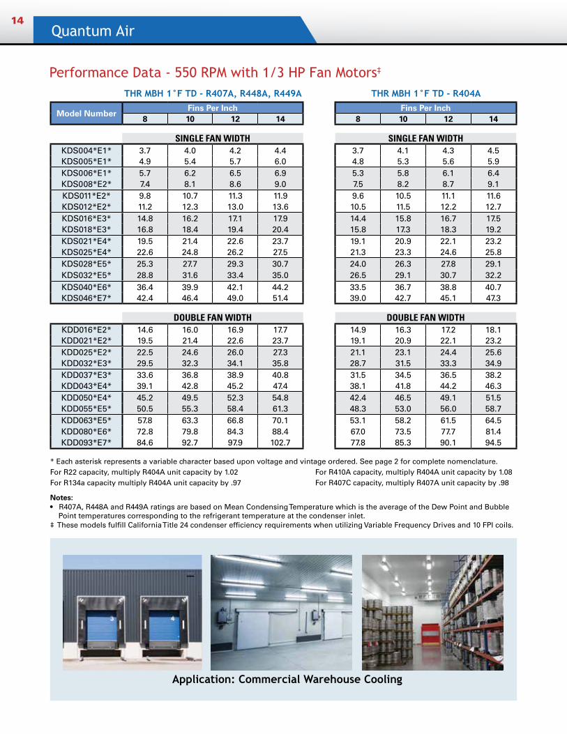
Performance Data - 550 RPM with 1/3 HP Fan Motors‡
THR MBH 1°F TD - R407A, R448A, R449A THR MBH 1°F TD - R404A
Model NumberFins Per Inch Fins Per Inch
8 10 12 14 8 10 12 14
SINGLE FAN WIDTH SINGLE FAN WIDTHKDS004*E1* 3.7 4.0 4.2 4.4 3.7 4.1 4.3 4.5KDS005*E1* 4.9 5.4 5.7 6.0 4.8 5.3 5.6 5.9KDS006*E1* 5.7 6.2 6.5 6.9 5.3 5.8 6.1 6.4KDS008*E2* 7.4 8.1 8.6 9.0 7.5 8.2 8.7 9.1KDS011*E2* 9.8 10.7 11.3 11.9 9.6 10.5 11.1 11.6KDS012*E2* 11.2 12.3 13.0 13.6 10.5 11.5 12.2 12.7KDS016*E3* 14.8 16.2 17.1 17.9 14.4 15.8 16.7 17.5KDS018*E3* 16.8 18.4 19.4 20.4 15.8 17.3 18.3 19.2KDS021*E4* 19.5 21.4 22.6 23.7 19.1 20.9 22.1 23.2KDS025*E4* 22.6 24.8 26.2 27.5 21.3 23.3 24.6 25.8KDS028*E5* 25.3 27.7 29.3 30.7 24.0 26.3 27.8 29.1KDS032*E5* 28.8 31.6 33.4 35.0 26.5 29.1 30.7 32.2KDS040*E6* 36.4 39.9 42.1 44.2 33.5 36.7 38.8 40.7KDS046*E7* 42.4 46.4 49.0 51.4 39.0 42.7 45.1 47.3
DOUBLE FAN WIDTH DOUBLE FAN WIDTHKDD016*E2* 14.6 16.0 16.9 17.7 14.9 16.3 17.2 18.1KDD021*E2* 19.5 21.4 22.6 23.7 19.1 20.9 22.1 23.2KDD025*E2* 22.5 24.6 26.0 27.3 21.1 23.1 24.4 25.6KDD032*E3* 29.5 32.3 34.1 35.8 28.7 31.5 33.3 34.9KDD037*E3* 33.6 36.8 38.9 40.8 31.5 34.5 36.5 38.2KDD043*E4* 39.1 42.8 45.2 47.4 38.1 41.8 44.2 46.3KDD050*E4* 45.2 49.5 52.3 54.8 42.4 46.5 49.1 51.5KDD055*E5* 50.5 55.3 58.4 61.3 48.3 53.0 56.0 58.7KDD063*E5* 57.8 63.3 66.8 70.1 53.1 58.2 61.5 64.5KDD080*E6* 72.8 79.8 84.3 88.4 67.0 73.5 77.7 81.4KDD093*E7* 84.6 92.7 97.9 102.7 77.8 85.3 90.1 94.5
Application: Commercial Warehouse Cooling
* Each asterisk represents a variable character based upon voltage and vintage ordered. See page 2 for complete nomenclature.For R22 capacity, multiply R404A unit capacity by 1.02 For R410A capacity, multiply R404A unit capacity by 1.08 For R134a capacity multiply R404A unit capacity by .97 For R407C capacity, multiply R407A unit capacity by .98
Notes:• R407A, R448A and R449A ratings are based on Mean Condensing Temperature which is the average of the Dew Point and Bubble
Point temperatures corresponding to the refrigerant temperature at the condenser inlet. ‡ These models fulfill California Title 24 condenser efficiency requirements when utilizing Variable Frequency Drives and 10 FPI coils.
Remote Air Cooled Condensers15
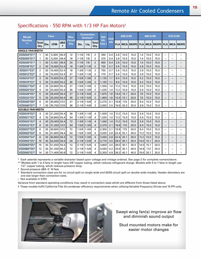
Specifications - 550 RPM with 1/3 HP Fan Motors‡
Model Number
**
Fans Max. Circuit
Qty.
Connection (Inches)^ Net
Wt. (Lbs.)
Unit kW
208/3/60 460/3/60 575/3/60
Total Qty.
Dia. CFMdBA
†Dis. Liq.
Total Qty.
FLA MCA MOPD FLA MCA MOPD FLA MCA MOPD
SINGLE FAN WIDTH
KDS004*E1* 1 30 5,300 49.4 12 1-1/8 7/8 2 350 0.4 2.8 15.0 15.0 1.4 15.0 15.0 – – –KDS005*E1* 1 30 5,200 49.4 18 1-1/8 7/8 2 375 0.4 2.8 15.0 15.0 1.4 15.0 15.0 – – –
KDS006*E1* 1 30 5,100 49.4 24 1-1/8 7/8 2 400 0.4 2.8 15.0 15.0 1.4 15.0 15.0 – – –KDS008*E2* 2 30 10,600 52.4 18 1-3/8 1-1/8 2 725 0.7 5.6 15.0 15.0 2.8 15.0 15.0 – – –
KDS011*E2* 2 30 10,400 52.4 18 1-3/8 1-1/8 2 750 0.7 5.6 15.0 15.0 2.8 15.0 15.0 – – –KDS012*E2* 2 30 10,200 52.4 27 1-3/8 1-1/8 2 775 0.7 5.6 15.0 15.0 2.8 15.0 15.0 – – –
KDS016*E3* 3 30 15,600 54.2 27 1-5/8 1-3/8 2 1,125 1.1 8.4 15.0 15.0 4.2 15.0 15.0 – – –KDS018*E3* 3 30 15,300 54.2 36 1-5/8 1-3/8 2 1,150 1.1 8.4 15.0 15.0 4.2 15.0 15.0 – – –
KDS021*E4* 4 30 20,800 55.4 27 1-5/8 1-3/8 2 1,500 1.4 11.2 15.0 15.0 5.6 15.0 15.0 – – –KDS025*E4* 4 30 20,400 55.4 36 1-5/8 1-3/8 2 1,525 1.4 11.2 15.0 15.0 5.6 15.0 15.0 – – –
KDS028*E5* 5 30 26,000 56.4 27 2-1/8 1-5/8 2 1,875 1.8 14.0 15.1 20.0 7.0 15.0 15.0 – – –KDS032*E5* 5 30 25,500 56.4 36 2-1/8 1-5/8 2 1,900 1.8 14.0 15.1 20.0 7.0 15.0 15.0 – – –
KDS040*E6* 6 30 30,600 57.2 27 2-1/8 1-5/8 2 2,275 2.1 16.8 17.5 20.0 8.4 15.0 15.0 – – –KDS046*E7* 7 30 35,700 57.8 36 2-1/8 1-5/8 2 2,650 2.5 19.6 20.3 25.0 9.8 15.0 15.0 – – –
DOUBLE FAN WIDTH
KDD016*E2* 4 30 21,200 55.4 36 1-3/8 1-1/8 4 1,500 1.4 11.2 15.0 15.0 5.6 15.0 15.0 – – –KDD021*E2* 4 30 20,800 55.4 54 1-3/8 1-1/8 4 1,525 1.4 11.2 15.0 15.0 5.6 15.0 15.0 – – –
KDD025*E2* 4 30 20,400 55.4 72 1-3/8 1-1/8 4 1,550 1.4 11.2 15.0 15.0 5.6 15.0 15.0 – – –KDD032*E3* 6 30 31,200 57.2 54 1-5/8 1-3/8 4 2,275 2.1 16.8 17.5 20.0 8.4 15.0 15.0 – – –
KDD037*E3* 6 30 30,600 57.2 72 1-5/8 1-3/8 4 2,300 2.1 16.8 17.5 20.0 8.4 15.0 15.0 – – –KDD043*E4* 8 30 41,600 58.4 54 1-5/8 1-3/8 4 3,025 2.8 22.4 25.1 30.0 11.2 15.0 15.0 – – –
KDD050*E4* 8 30 40,800 58.4 72 1-5/8 1-3/8 4 3,050 2.8 22.4 25.1 30.0 11.2 15.0 15.0 – – –KDD055*E5* 10 30 52,000 59.4 54 2-1/8 1-5/8 4 3,775 3.5 28.0 30.1 35.0 14.0 15.1 20.0 – – –
KDD063*E5* 10 30 51,000 59.4 72 2-1/8 1-5/8 4 3,800 3.5 28.0 30.1 35.0 14.0 15.1 20.0 – – –KDD080*E6* 12 30 61,200 60.2 72 2-1/8 1-5/8 4 4,550 4.2 33.6 35.1 40.0 16.8 17.2 20.0 – – –KDD093*E7* 14 30 71,400 60.8 72 2-1/8 1-5/8 4 5,300 4.9 39.2 40.1 45.0 19.6 20.1 25.0 – – –
Swept wing fan(s) improve air flow and diminish sound output
Stud mounted motors make for easier motor changes
* Each asterisk represents a variable character based upon voltage and vintage ordered. See page 2 for complete nomenclature.** Models with 1 to 4 fans in length have 3/8”copper tubing, which reduces refrigerant charge. Models with 5 to 7 fans in length use
1/2” copper tubing, which reduces pressure drop. † Sound pressure dBA @ 10 feet.^ Standard connection sizes are for no circuit split on single wide and 50/50 circuit split on double wide models. Header diameters are
one size larger than connection sizes. – Not available in 575V.Variance from standard operating conditions may result in connection sizes which are different from those listed above.‡ These models fulfill California Title 24 condenser efficiency requirements when utilizing Variable Frequency Drives and 10 FPI coils.
Quantum Air16
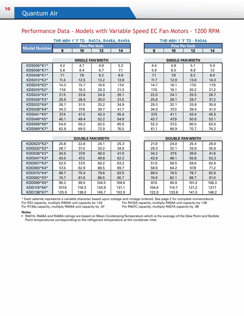
Performance Data - Models with Variable Speed EC Fan Motors - 1200 RPM
THR MBH 1°F TD - R407A, R448A, R449A THR MBH 1°F TD - R404A
Model Number Fins Per Inch Fins Per Inch8 10 12 14 8 10 12 14
SINGLE FAN WIDTH SINGLE FAN WIDTHKDS005*K1* 4.2 4.7 4.9 5.2 4.4 4.9 5.1 5.4KDS006*K1* 5.8 6.4 6.7 7.1 5.9 6.5 6.9 7.2KDS008*K1* 7.1 7.8 8.2 8.6 7.1 7.8 8.2 8.6KDS013*K2* 11.4 12.5 13.2 13.9 11.7 12.9 13.6 14.3KDS016*K2* 14.3 15.7 16.6 17.4 14.7 16.1 17.0 17.9KDS019*K2* 17.6 19.3 20.3 21.3 17.5 19.1 20.2 21.2KDS024*K3* 21.5 23.6 24.9 26.1 22.0 24.1 25.5 26.7KDS028*K3* 25.9 28.4 30.0 31.5 25.6 28.1 29.7 31.2KDS032*K4* 28.7 31.5 33.2 34.9 29.3 32.1 33.9 35.6KDS038*K4* 34.3 37.6 39.7 41.7 34.0 37.3 39.4 41.3KDS041*K5* 37.4 41.0 43.3 45.4 37.5 41.1 43.4 45.5KDS049*K5* 45.1 49.4 52.2 54.8 43.7 47.9 50.6 53.1KDS059*K6* 54.0 59.2 62.5 65.5 52.3 57.3 60.5 63.5KDS069*K7* 62.9 69.0 72.9 76.5 61.1 66.9 70.7 74.2
DOUBLE FAN WIDTH DOUBLE FAN WIDTHKDD023*K2* 20.8 22.8 24.1 25.3 21.9 24.0 25.4 26.6KDD032*K2* 28.7 31.5 33.2 34.9 29.3 32.1 33.9 35.6KDD038*K2* 34.5 37.9 40.0 41.9 34.2 37.5 39.6 41.6KDD047*K3* 43.0 47.2 49.8 52.2 43.9 48.1 50.8 53.3KDD057*K3* 52.0 57.0 60.2 63.2 51.5 56.5 59.6 62.6KDD063*K4* 57.4 62.9 66.5 69.7 58.6 64.2 67.8 71.2KDD075*K4* 68.7 75.4 79.6 83.5 68.0 74.5 78.7 82.6KDD082*K5* 74.7 81.9 86.5 90.7 74.9 82.1 86.7 91.0KDD099*K5* 90.2 99.0 104.5 109.6 87.5 95.9 101.3 106.3KDD118*K6* 107.9 118.3 124.9 131.1 104.6 114.7 121.2 127.1KDD138*K7* 125.9 138.0 145.7 152.9 122.0 133.8 141.3 148.2
* Each asterisk represents a variable character based upon voltage and vintage ordered. See page 2 for complete nomenclature.For R22 capacity, multiply R404A unit capacity by 1.02 For R410A capacity, multiply R404A unit capacity by 1.08 For R134a capacity, multiply R404A unit capacity by .97 For R407C capacity, multiply R407A capacity by .98
Notes: • R407A, R448A and R449A ratings are based on Mean Condensing Temperature which is the average of the Dew Point and Bubble
Point temperatures corresponding to the refrigerant temperature at the condenser inlet.
Remote Air Cooled Condensers17
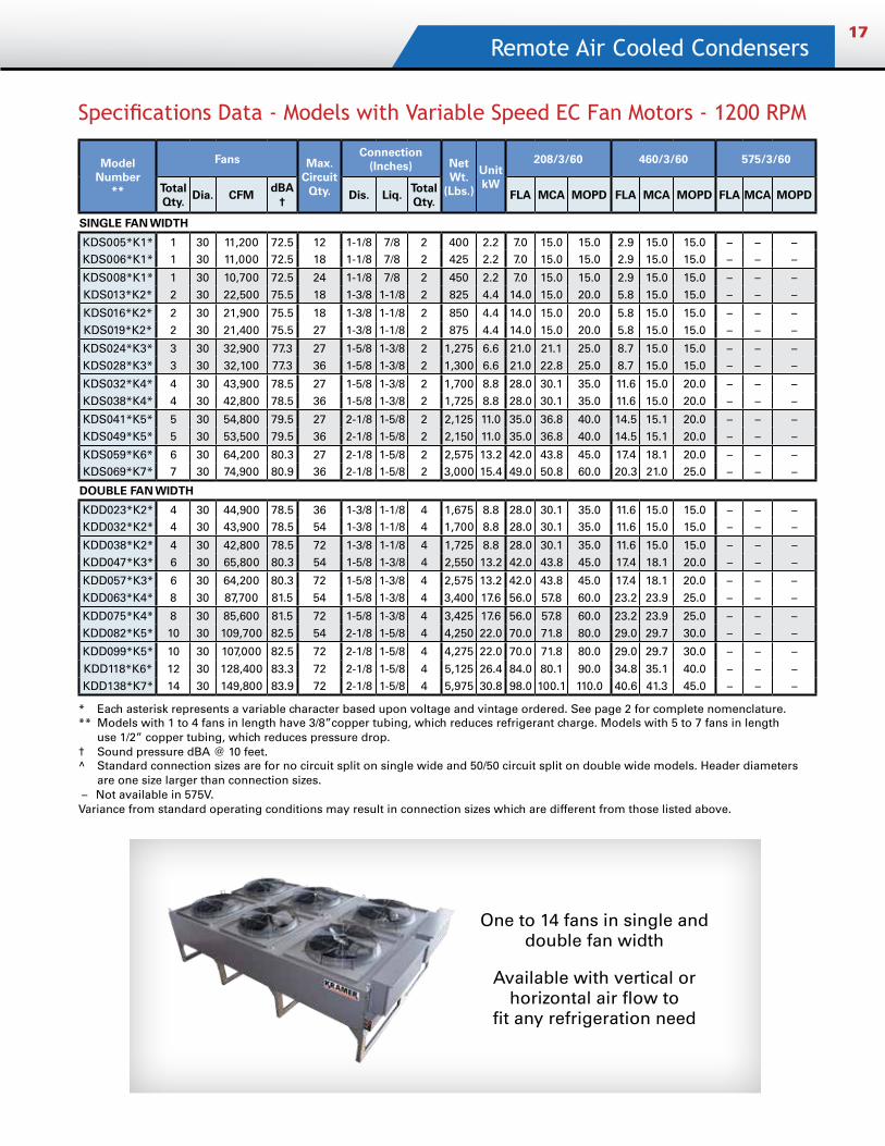
Specifications Data - Models with Variable Speed EC Fan Motors - 1200 RPM
Model Number
**
Fans Max. Circuit
Qty.
Connection (Inches) Net
Wt. (Lbs.)
Unit kW
208/3/60 460/3/60 575/3/60
Total Qty.
Dia. CFMdBA
†Dis. Liq.
Total Qty.
FLA MCA MOPD FLA MCA MOPD FLA MCA MOPD
SINGLE FAN WIDTH
KDS005*K1* 1 30 11,200 72.5 12 1-1/8 7/8 2 400 2.2 7.0 15.0 15.0 2.9 15.0 15.0 – – –KDS006*K1* 1 30 11,000 72.5 18 1-1/8 7/8 2 425 2.2 7.0 15.0 15.0 2.9 15.0 15.0 – – –
KDS008*K1* 1 30 10,700 72.5 24 1-1/8 7/8 2 450 2.2 7.0 15.0 15.0 2.9 15.0 15.0 – – –KDS013*K2* 2 30 22,500 75.5 18 1-3/8 1-1/8 2 825 4.4 14.0 15.0 20.0 5.8 15.0 15.0 – – –
KDS016*K2* 2 30 21,900 75.5 18 1-3/8 1-1/8 2 850 4.4 14.0 15.0 20.0 5.8 15.0 15.0 – – –KDS019*K2* 2 30 21,400 75.5 27 1-3/8 1-1/8 2 875 4.4 14.0 15.0 20.0 5.8 15.0 15.0 – – –
KDS024*K3* 3 30 32,900 77.3 27 1-5/8 1-3/8 2 1,275 6.6 21.0 21.1 25.0 8.7 15.0 15.0 – – –KDS028*K3* 3 30 32,100 77.3 36 1-5/8 1-3/8 2 1,300 6.6 21.0 22.8 25.0 8.7 15.0 15.0 – – –
KDS032*K4* 4 30 43,900 78.5 27 1-5/8 1-3/8 2 1,700 8.8 28.0 30.1 35.0 11.6 15.0 20.0 – – –KDS038*K4* 4 30 42,800 78.5 36 1-5/8 1-3/8 2 1,725 8.8 28.0 30.1 35.0 11.6 15.0 20.0 – – –
KDS041*K5* 5 30 54,800 79.5 27 2-1/8 1-5/8 2 2,125 11.0 35.0 36.8 40.0 14.5 15.1 20.0 – – –KDS049*K5* 5 30 53,500 79.5 36 2-1/8 1-5/8 2 2,150 11.0 35.0 36.8 40.0 14.5 15.1 20.0 – – –
KDS059*K6* 6 30 64,200 80.3 27 2-1/8 1-5/8 2 2,575 13.2 42.0 43.8 45.0 17.4 18.1 20.0 – – –KDS069*K7* 7 30 74,900 80.9 36 2-1/8 1-5/8 2 3,000 15.4 49.0 50.8 60.0 20.3 21.0 25.0 – – –
DOUBLE FAN WIDTH
KDD023*K2* 4 30 44,900 78.5 36 1-3/8 1-1/8 4 1,675 8.8 28.0 30.1 35.0 11.6 15.0 15.0 – – –KDD032*K2* 4 30 43,900 78.5 54 1-3/8 1-1/8 4 1,700 8.8 28.0 30.1 35.0 11.6 15.0 15.0 – – –
KDD038*K2* 4 30 42,800 78.5 72 1-3/8 1-1/8 4 1,725 8.8 28.0 30.1 35.0 11.6 15.0 15.0 – – –KDD047*K3* 6 30 65,800 80.3 54 1-5/8 1-3/8 4 2,550 13.2 42.0 43.8 45.0 17.4 18.1 20.0 – – –
KDD057*K3* 6 30 64,200 80.3 72 1-5/8 1-3/8 4 2,575 13.2 42.0 43.8 45.0 17.4 18.1 20.0 – – –KDD063*K4* 8 30 87,700 81.5 54 1-5/8 1-3/8 4 3,400 17.6 56.0 57.8 60.0 23.2 23.9 25.0 – – –
KDD075*K4* 8 30 85,600 81.5 72 1-5/8 1-3/8 4 3,425 17.6 56.0 57.8 60.0 23.2 23.9 25.0 – – –KDD082*K5* 10 30 109,700 82.5 54 2-1/8 1-5/8 4 4,250 22.0 70.0 71.8 80.0 29.0 29.7 30.0 – – –
KDD099*K5* 10 30 107,000 82.5 72 2-1/8 1-5/8 4 4,275 22.0 70.0 71.8 80.0 29.0 29.7 30.0 – – –
KDD118*K6* 12 30 128,400 83.3 72 2-1/8 1-5/8 4 5,125 26.4 84.0 80.1 90.0 34.8 35.1 40.0 – – –KDD138*K7* 14 30 149,800 83.9 72 2-1/8 1-5/8 4 5,975 30.8 98.0 100.1 110.0 40.6 41.3 45.0 – – –
* Each asterisk represents a variable character based upon voltage and vintage ordered. See page 2 for complete nomenclature.** Models with 1 to 4 fans in length have 3/8”copper tubing, which reduces refrigerant charge. Models with 5 to 7 fans in length use 1/2” copper tubing, which reduces pressure drop.† Sound pressure dBA @ 10 feet.^ Standard connection sizes are for no circuit split on single wide and 50/50 circuit split on double wide models. Header diameters are one size larger than connection sizes. – Not available in 575V.Variance from standard operating conditions may result in connection sizes which are different from those listed above.
One to 14 fans in single and double fan width
Available with vertical or horizontal air flow to
fit any refrigeration need
Quantum Air18
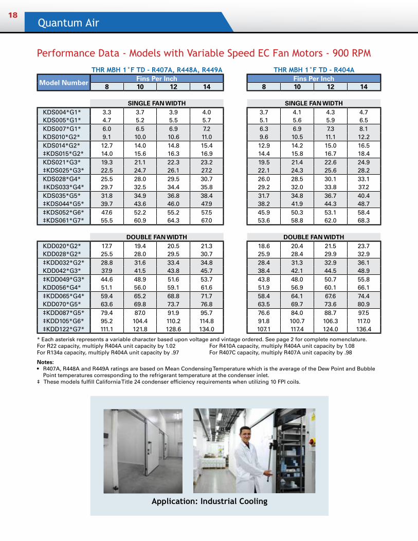
Performance Data - Models with Variable Speed EC Fan Motors - 900 RPM
THR MBH 1°F TD - R407A, R448A, R449A THR MBH 1°F TD - R404A
Model Number Fins Per Inch Fins Per Inch8 10 12 14 8 10 12 14
SINGLE FAN WIDTH SINGLE FAN WIDTHKDS004*G1* 3.3 3.7 3.9 4.0 3.7 4.1 4.3 4.7KDS005*G1* 4.7 5.2 5.5 5.7 5.1 5.6 5.9 6.5KDS007*G1* 6.0 6.5 6.9 7.2 6.3 6.9 7.3 8.1KDS010*G2* 9.1 10.0 10.6 11.0 9.6 10.5 11.1 12.2KDS014*G2* 12.7 14.0 14.8 15.4 12.9 14.2 15.0 16.5‡KDS015*G2* 14.0 15.6 16.3 16.9 14.4 15.8 16.7 18.4KDS021*G3* 19.3 21.1 22.3 23.2 19.5 21.4 22.6 24.9‡KDS025*G3* 22.5 24.7 26.1 27.2 22.1 24.3 25.6 28.2KDS028*G4* 25.5 28.0 29.5 30.7 26.0 28.5 30.1 33.1‡KDS033*G4* 29.7 32.5 34.4 35.8 29.2 32.0 33.8 37.2KDS035*G5* 31.8 34.9 36.8 38.4 31.7 34.8 36.7 40.4‡KDS044*G5* 39.7 43.6 46.0 47.9 38.2 41.9 44.3 48.7‡KDS052*G6* 47.6 52.2 55.2 57.5 45.9 50.3 53.1 58.4‡KDS061*G7* 55.5 60.9 64.3 67.0 53.6 58.8 62.0 68.3
DOUBLE FAN WIDTH DOUBLE FAN WIDTHKDD020*G2* 17.7 19.4 20.5 21.3 18.6 20.4 21.5 23.7KDD028*G2* 25.5 28.0 29.5 30.7 25.9 28.4 29.9 32.9‡KDD032*G2* 28.8 31.6 33.4 34.8 28.4 31.3 32.9 36.1KDD042*G3* 37.9 41.5 43.8 45.7 38.4 42.1 44.5 48.9‡KDD049*G3* 44.6 48.9 51.6 53.7 43.8 48.0 50.7 55.8KDD056*G4* 51.1 56.0 59.1 61.6 51.9 56.9 60.1 66.1‡KDD065*G4* 59.4 65.2 68.8 71.7 58.4 64.1 67.6 74.4KDD070*G5* 63.6 69.8 73.7 76.8 63.5 69.7 73.6 80.9‡KDD087*G5* 79.4 87.0 91.9 95.7 76.6 84.0 88.7 97.5‡KDD105*G6* 95.2 104.4 110.2 114.8 91.8 100.7 106.3 117.0‡KDD122*G7* 111.1 121.8 128.6 134.0 107.1 117.4 124.0 136.4
* Each asterisk represents a variable character based upon voltage and vintage ordered. See page 2 for complete nomenclature.For R22 capacity, multiply R404A unit capacity by 1.02 For R410A capacity, multiply R404A unit capacity by 1.08 For R134a capacity, multiply R404A unit capacity by .97 For R407C capacity, multiply R407A unit capacity by .98
Notes: • R407A, R448A and R449A ratings are based on Mean Condensing Temperature which is the average of the Dew Point and Bubble
Point temperatures corresponding to the refrigerant temperature at the condenser inlet. ‡ These models fulfill California Title 24 condenser efficiency requirements when utilizing 10 FPI coils.
Application: Industrial Cooling
Remote Air Cooled Condensers19
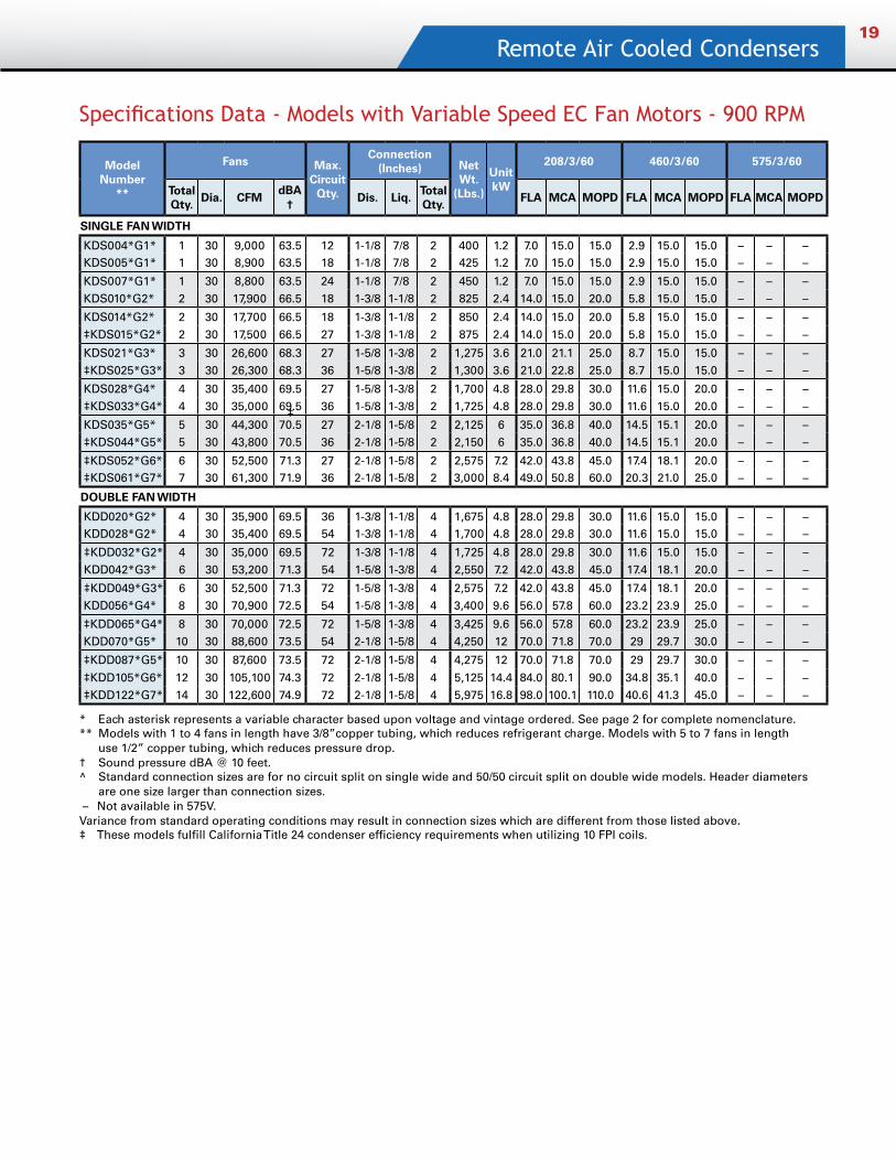
Specifications Data - Models with Variable Speed EC Fan Motors - 900 RPM
Model Number
**
Fans Max. Circuit
Qty.
Connection (Inches) Net
Wt. (Lbs.)
Unit kW
208/3/60 460/3/60 575/3/60
Total Qty.
Dia. CFMdBA
†Dis. Liq.
Total Qty.
FLA MCA MOPD FLA MCA MOPD FLA MCA MOPD
SINGLE FAN WIDTH
KDS004*G1* 1 30 9,000 63.5 12 1-1/8 7/8 2 400 1.2 7.0 15.0 15.0 2.9 15.0 15.0 – – –KDS005*G1* 1 30 8,900 63.5 18 1-1/8 7/8 2 425 1.2 7.0 15.0 15.0 2.9 15.0 15.0 – – –
KDS007*G1* 1 30 8,800 63.5 24 1-1/8 7/8 2 450 1.2 7.0 15.0 15.0 2.9 15.0 15.0 – – –KDS010*G2* 2 30 17,900 66.5 18 1-3/8 1-1/8 2 825 2.4 14.0 15.0 20.0 5.8 15.0 15.0 – – –
KDS014*G2* 2 30 17,700 66.5 18 1-3/8 1-1/8 2 850 2.4 14.0 15.0 20.0 5.8 15.0 15.0 – – –‡KDS015*G2* 2 30 17,500 66.5 27 1-3/8 1-1/8 2 875 2.4 14.0 15.0 20.0 5.8 15.0 15.0 – – –
KDS021*G3* 3 30 26,600 68.3 27 1-5/8 1-3/8 2 1,275 3.6 21.0 21.1 25.0 8.7 15.0 15.0 – – –‡KDS025*G3* 3 30 26,300 68.3 36 1-5/8 1-3/8 2 1,300 3.6 21.0 22.8 25.0 8.7 15.0 15.0 – – –
KDS028*G4* 4 30 35,400 69.5 27 1-5/8 1-3/8 2 1,700 4.8 28.0 29.8 30.0 11.6 15.0 20.0 – – –‡KDS033*G4* 4 30 35,000 69.5 36 1-5/8 1-3/8 2 1,725 4.8 28.0 29.8 30.0 11.6 15.0 20.0 – – –
KDS035*G5* 5 30 44,300 70.5 27 2-1/8 1-5/8 2 2,125 6 35.0 36.8 40.0 14.5 15.1 20.0 – – –‡KDS044*G5* 5 30 43,800 70.5 36 2-1/8 1-5/8 2 2,150 6 35.0 36.8 40.0 14.5 15.1 20.0 – – –
‡KDS052*G6* 6 30 52,500 71.3 27 2-1/8 1-5/8 2 2,575 7.2 42.0 43.8 45.0 17.4 18.1 20.0 – – –‡KDS061*G7* 7 30 61,300 71.9 36 2-1/8 1-5/8 2 3,000 8.4 49.0 50.8 60.0 20.3 21.0 25.0 – – –
DOUBLE FAN WIDTH
KDD020*G2* 4 30 35,900 69.5 36 1-3/8 1-1/8 4 1,675 4.8 28.0 29.8 30.0 11.6 15.0 15.0 – – –KDD028*G2* 4 30 35,400 69.5 54 1-3/8 1-1/8 4 1,700 4.8 28.0 29.8 30.0 11.6 15.0 15.0 – – –
‡KDD032*G2* 4 30 35,000 69.5 72 1-3/8 1-1/8 4 1,725 4.8 28.0 29.8 30.0 11.6 15.0 15.0 – – –KDD042*G3* 6 30 53,200 71.3 54 1-5/8 1-3/8 4 2,550 7.2 42.0 43.8 45.0 17.4 18.1 20.0 – – –
‡KDD049*G3* 6 30 52,500 71.3 72 1-5/8 1-3/8 4 2,575 7.2 42.0 43.8 45.0 17.4 18.1 20.0 – – –KDD056*G4* 8 30 70,900 72.5 54 1-5/8 1-3/8 4 3,400 9.6 56.0 57.8 60.0 23.2 23.9 25.0 – – –
‡KDD065*G4* 8 30 70,000 72.5 72 1-5/8 1-3/8 4 3,425 9.6 56.0 57.8 60.0 23.2 23.9 25.0 – – –KDD070*G5* 10 30 88,600 73.5 54 2-1/8 1-5/8 4 4,250 12 70.0 71.8 70.0 29 29.7 30.0 – – –
‡KDD087*G5* 10 30 87,600 73.5 72 2-1/8 1-5/8 4 4,275 12 70.0 71.8 70.0 29 29.7 30.0 – – –
‡KDD105*G6* 12 30 105,100 74.3 72 2-1/8 1-5/8 4 5,125 14.4 84.0 80.1 90.0 34.8 35.1 40.0 – – –‡KDD122*G7* 14 30 122,600 74.9 72 2-1/8 1-5/8 4 5,975 16.8 98.0 100.1 110.0 40.6 41.3 45.0 – – –
* Each asterisk represents a variable character based upon voltage and vintage ordered. See page 2 for complete nomenclature.** Models with 1 to 4 fans in length have 3/8”copper tubing, which reduces refrigerant charge. Models with 5 to 7 fans in length use 1/2” copper tubing, which reduces pressure drop.† Sound pressure dBA @ 10 feet.^ Standard connection sizes are for no circuit split on single wide and 50/50 circuit split on double wide models. Header diameters are one size larger than connection sizes. – Not available in 575V.Variance from standard operating conditions may result in connection sizes which are different from those listed above.‡ These models fulfill California Title 24 condenser efficiency requirements when utilizing 10 FPI coils.
‡
Quantum Air20
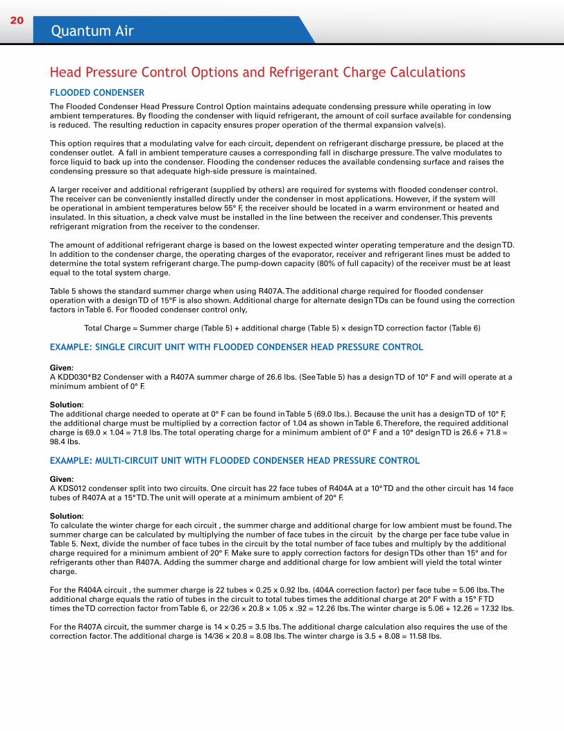
Head Pressure Control Options and Refrigerant Charge CalculationsFLOODED CONDENSERThe Flooded Condenser Head Pressure Control Option maintains adequate condensing pressure while operating in low ambient temperatures. By flooding the condenser with liquid refrigerant, the amount of coil surface available for condensing is reduced. The resulting reduction in capacity ensures proper operation of the thermal expansion valve(s).
This option requires that a modulating valve for each circuit, dependent on refrigerant discharge pressure, be placed at the condenser outlet. A fall in ambient temperature causes a corresponding fall in discharge pressure. The valve modulates to force liquid to back up into the condenser. Flooding the condenser reduces the available condensing surface and raises the condensing pressure so that adequate high-side pressure is maintained.
A larger receiver and additional refrigerant (supplied by others) are required for systems with flooded condenser control. The receiver can be conveniently installed directly under the condenser in most applications. However, if the system will be operational in ambient temperatures below 55° F, the receiver should be located in a warm environment or heated and insulated. In this situation, a check valve must be installed in the line between the receiver and condenser. This prevents refrigerant migration from the receiver to the condenser.
The amount of additional refrigerant charge is based on the lowest expected winter operating temperature and the design TD. In addition to the condenser charge, the operating charges of the evaporator, receiver and refrigerant lines must be added to determine the total system refrigerant charge. The pump-down capacity (80% of full capacity) of the receiver must be at least equal to the total system charge.
Table 5 shows the standard summer charge when using R407A. The additional charge required for flooded condenser operation with a design TD of 15°F is also shown. Additional charge for alternate design TDs can be found using the correction factors in Table 6. For flooded condenser control only,
Total Charge = Summer charge (Table 5) + additional charge (Table 5) × design TD correction factor (Table 6)
EXAMPLE: SINGLE CIRCUIT UNIT WITH FLOODED CONDENSER HEAD PRESSURE CONTROL
Given:A KDD030*B2 Condenser with a R407A summer charge of 26.6 lbs. (See Table 5) has a design TD of 10° F and will operate at a minimum ambient of 0° F.
Solution:The additional charge needed to operate at 0° F can be found in Table 5 (69.0 lbs.). Because the unit has a design TD of 10° F, the additional charge must be multiplied by a correction factor of 1.04 as shown in Table 6. Therefore, the required additional charge is 69.0 × 1.04 = 71.8 lbs. The total operating charge for a minimum ambient of 0° F and a 10° design TD is 26.6 + 71.8 = 98.4 lbs.
EXAMPLE: MULTI-CIRCUIT UNIT WITH FLOODED CONDENSER HEAD PRESSURE CONTROL
Given:A KDS012 condenser split into two circuits. One circuit has 22 face tubes of R404A at a 10° TD and the other circuit has 14 face tubes of R407A at a 15° TD. The unit will operate at a minimum ambient of 20° F.
Solution:To calculate the winter charge for each circuit , the summer charge and additional charge for low ambient must be found. The summer charge can be calculated by multiplying the number of face tubes in the circuit by the charge per face tube value in Table 5. Next, divide the number of face tubes in the circuit by the total number of face tubes and multiply by the additional charge required for a minimum ambient of 20° F. Make sure to apply correction factors for design TDs other than 15° and for refrigerants other than R407A. Adding the summer charge and additional charge for low ambient will yield the total winter charge.
For the R404A circuit , the summer charge is 22 tubes × 0.25 x 0.92 lbs. (404A correction factor) per face tube = 5.06 lbs. The additional charge equals the ratio of tubes in the circuit to total tubes times the additional charge at 20° F with a 15° F TD times the TD correction factor from Table 6, or 22/36 × 20.8 × 1.05 x .92 = 12.26 lbs. The winter charge is 5.06 + 12.26 = 17.32 lbs.
For the R407A circuit, the summer charge is 14 × 0.25 = 3.5 lbs. The additional charge calculation also requires the use of the correction factor. The additional charge is 14/36 × 20.8 = 8.08 lbs. The winter charge is 3.5 + 8.08 = 11.58 lbs.
Remote Air Cooled Condensers21
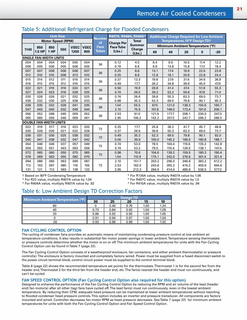
Table 5: Additional Refrigerant Charge for Flooded Condensers
FAN CYCLING CONTROL OPTIONThe cycling of condenser fans provides an automatic means of maintaining condensing pressure control at low ambient air temperature conditions. It also results in substantial fan motor power savings in lower ambient. Temperature sensing thermostats or pressure controls determine whether the motor is on or off. The minimum ambient temperatures for units with the Fan Cycling Control Option can be found in Table 7 (page 22).
The Fan Cycling Control Option consists of a weatherproof enclosure, fan contactors, and either ambient thermostat(s) or pressure control(s). The enclosure is factory mounted and completely factory wired. Power must be supplied from a fused disconnect switch to the power circuit terminal block; control circuit power must be supplied to the control terminal block.
Table 8 (page 22) shows the recommended temperature set points for the thermostats. Thermostat 1 is for the second fan from the header end, Thermostat 2 for the third fan from the header end, etc. The fan(s) nearest the header end must run continuously, and can’t be cycled.
FAN SPEED CONTROL OPTION (Fan Cycling Control Option also required for this option)Designed to enhance the performance of the Fan Cycling Control Option by reducing the RPM and air volume of the lead (header end) fan motor(s) after all other (lag) fans have cycled off. The lead fan(s) must run continuously, even in the lowest ambient temperature. By reducing their CFM, adequate head pressure can be maintained at lower ambient temperatures without resorting to flooded condenser head pressure controls. This option includes an inverter and pressure transducer. All components are factory mounted and wired. Controller decreases fan motor RPM as head pressure decreases. See Table 7 (page 22) for minimum ambient temperatures for units with both the Fan Cycling Control Option and Fan Speed Control Option.
Table 6: Low Ambient Design TD Correction Factors
Minimum Ambient Temperature (°F) Design TD30 25 20 15 10
60 0 0.40 0.76 1.00 1.2440 0.73 0.84 0.92 1.00 1.0920 0.86 0.92 0.95 1.00 1.050 0.91 0.94 0.97 1.00 1.04
-20 0.93 0.96 0.98 1.00 1.02
Unit SizeNumber
of Face
Tubes
R407A, R448A, R449A* Additional Charge Required for Low Ambient Temperatures,15°F Design TD† Motor Speed (RPM) Charge Per
Face Tube (Lbs.)
Total Summer Charge (Lbs.)
1140850
1.5 HP8501 HP
550VSEC 1200
VSEC900
Minimum Ambient Temperature (°F)
60 40 20 0 -20
SINGLE FAN-WIDTH UNITS004 004 004 004 005 004
360.12 4.5 6.4 9.0 10.5 11.4 12.2
006 005 006 005 006 005 0.19 6.6 9.9 13.8 15.8 17.2 18.4007 007 008 006 008 007
360.25 8.8 13.1 17.4 19.9 22.6 23.8
012 010 010 008 013 010 0.25 8.8 12.9 18.1 20.8 22.8 24.4015 014 012 011 016 014
360.37 13.3 19.8 27.6 31.6 34.6 36.8
018 015 015 012 019 015 0.49 17.7 26.2 34.8 39.9 45.0 47.6022 021 019 016 024 021
360.56 19.9 29.8 41.4 47.4 51.8 55.3
027 024 023 018 028 025 0.74 26.5 39.2 52.2 59.8 67.6 71.4030 028 026 021 032 025
360.74 26.6 39.8 55.3 63.3 69.0 73.7
036 032 030 025 038 033 0.98 35.3 52.3 69.5 79.8 90.1 95.3039 035 032 028 041 035
361.54 55.5 87.5 121.0 138.3 150.6 160.7
047 043 040 032 049 044 2.10 75.9 101.6 148.0 173.4 191.6 206.1056 052 048 040 059 052
362.53 91.0 121.9 177.7 208.1 230.0 247.3
065 060 056 046 069 061 2.95 106.2 142.2 207.2 242.7 268.2 288.5DOUBLE FAN-WIDTH UNITS
022 019 017 016 023 02072
0.25 17.7 25.8 36.2 41.7 45.7 48.8030 028 026 021 032 028 0.37 26.6 39.8 55.3 63.3 69.0 73.7036 031 030 025 038 032
720.49 35.3 52.3 69.5 79.8 90.1 92.0
045 041 038 032 047 042 0.56 39.9 105.0 145.2 166.0 180.8 188.1054 048 046 037 057 049
720.74 53.0 78.5 104.4 119.6 135.2 142.8
059 055 051 043 063 056 0.74 53.2 79.5 110.4 126.5 138.1 147.4072 065 060 050 075 065
720.98 70.6 104.6 139.2 159.5 180.3 190.4
078 069 063 055 082 070 1.54 110.9 175.1 242.0 276.6 301.4 321.4094 086 080 063 099 087
722.10 151.7 203.2 296.0 346.8 383.2 412.2
113 103 097 080 118 105 2.53 182.0 243.8 355.2 416.2 459.9 494.6131 121 113 093 138 122 2.95 212.3 284.5 414.4 485.6 536.5 577.2
† Based on 90°F Condensing Temperature * For R134A value, multiply R407A value by 1.06 * For R22 value, multiply R407A value by 1.04 * For R407C value, multiply R407A value by 1.0* For R404A value, multiply R407A value by .92 * For R410A value, multiply R407A value by .94
Quantum Air22
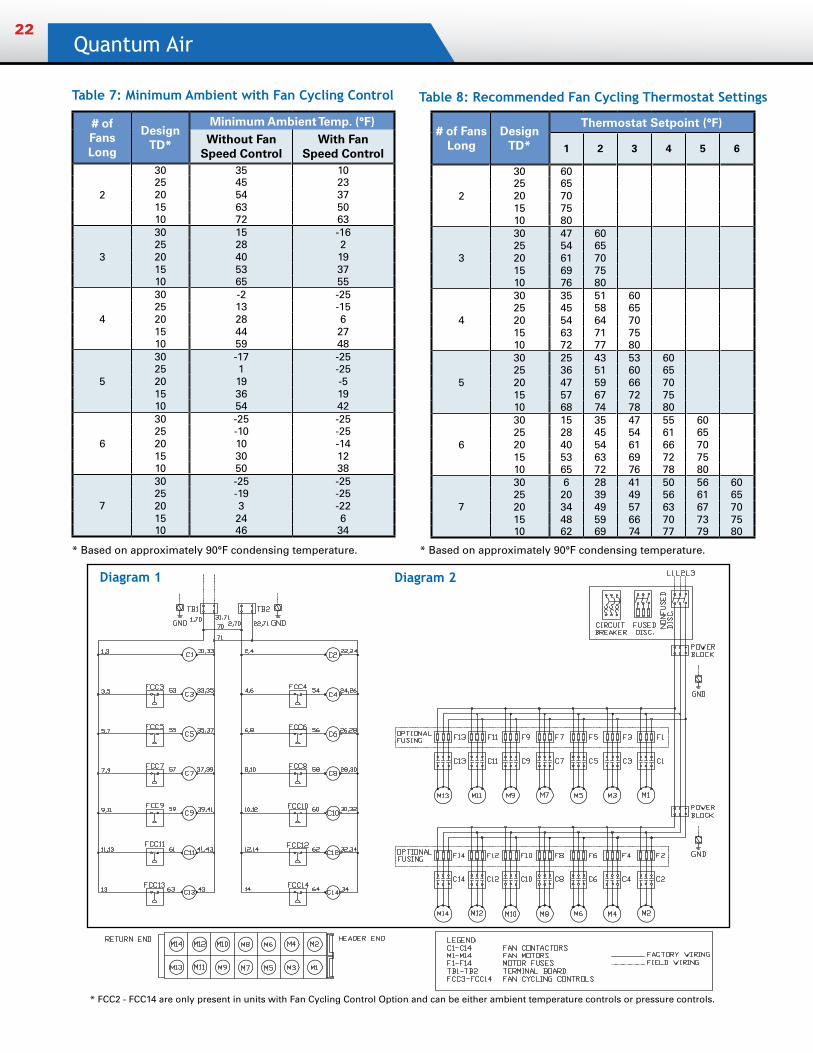
Table 7: Minimum Ambient with Fan Cycling Control Table 8: Recommended Fan Cycling Thermostat Settings
* Based on approximately 90°F condensing temperature.
* FCC2 - FCC14 are only present in units with Fan Cycling Control Option and can be either ambient temperature controls or pressure controls.
Diagram 1
# of Fans Long
Design TD*
Minimum Ambient Temp. (°F)Without Fan
Speed ControlWith Fan
Speed Control
2
30 35 1025 45 2320 54 3715 63 5010 72 63
3
30 15 -1625 28 220 40 1915 53 3710 65 55
4
30 -2 -2525 13 -1520 28 615 44 2710 59 48
5
30 -17 -2525 1 -2520 19 -515 36 1910 54 42
6
30 -25 -2525 -10 -2520 10 -1415 30 1210 50 38
7
30 -25 -2525 -19 -2520 3 -2215 24 610 46 34
* FCC3 - FCC14 are only present in units with Fan Cycling Control Option and can be either ambient temperature controls or pressure controls.
# of Fans Long
Design TD*
Thermostat Setpoint (°F)
1 2 3 4 5 6
2
30 6025 6520 7015 7510 80
3
30 47 6025 54 6520 61 7015 69 7510 76 80
4
30 35 51 6025 45 58 6520 54 64 7015 63 71 7510 72 77 80
5
30 25 43 53 6025 36 51 60 6520 47 59 66 7015 57 67 72 7510 68 74 78 80
6
30 15 35 47 55 6025 28 45 54 61 6520 40 54 61 66 7015 53 63 69 72 7510 65 72 76 78 80
7
30 6 28 41 50 56 6025 20 39 49 56 61 6520 34 49 57 63 67 7015 48 59 66 70 73 7510 62 69 74 77 79 80
* Based on approximately 90°F condensing temperature.
Diagram 2
Remote Air Cooled Condensers23
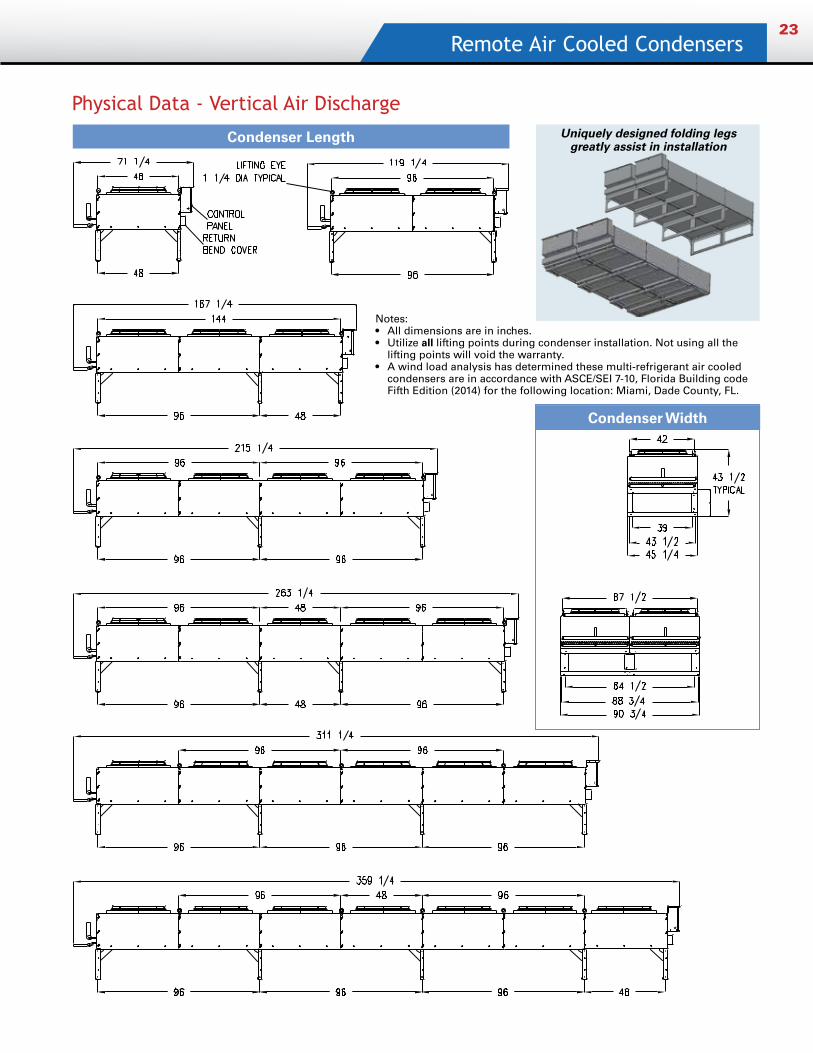
Physical Data - Vertical Air Discharge
Condenser Length Uniquely designed folding legs greatly assist in installation
Notes: • All dimensions are in inches.• Utilize all lifting points during condenser installation. Not using all the
lifting points will void the warranty.• A wind load analysis has determined these multi-refrigerant air cooled
condensers are in accordance with ASCE/SEI 7-10, Florida Building code Fifth Edition (2014) for the following location: Miami, Dade County, FL.
Condenser Width
Quantum Series
3885 Crestwood Pkwy., Ste. 500 • Duluth, Georgia 30096 • PHONE (678) 323-4904 • FAX (678) 323-4920 • kramer.htpg.com E-mail or call us for help: [email protected] or (800) 288-9488
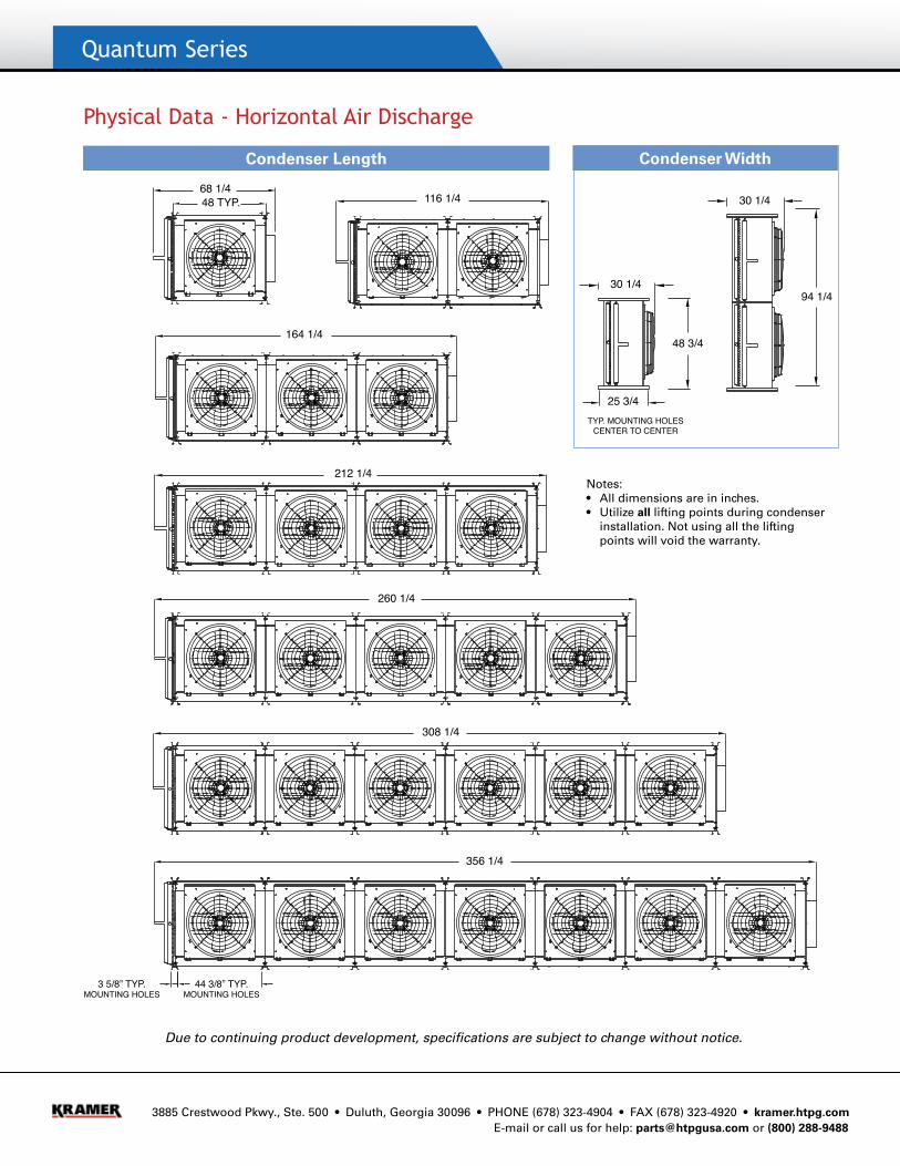
Physical Data - Horizontal Air Discharge
Due to continuing product development, specifications are subject to change without notice.
Notes: • All dimensions are in inches.• Utilize all lifting points during condenser
installation. Not using all the lifting points will void the warranty.
Condenser WidthCondenser Length
308 1/4
260 1/4
212 1/4
164 1/4
116 1/468 1/448 TYP.
356 1/4
30 1/4
30 1/4
94 1/4
48 3/4
25 3/4TYP. MOUNTING HOLES
CENTER TO CENTER
3 5/8” TYP.MOUNTING HOLES
CENTER TO CENTER
44 3/8” TYP.MOUNTING HOLES
CENTER TO CENTER