Embed Size (px)
Citation preview
Sumber : http://auto.howstuffworks.com Page 1 of 13 xtia/9/20/2007
PENGUNGKIT dan APLIKASINYA
How Tackle Works If you have ever looked at the end of a crane, or if you have ever used an engine hoist or a
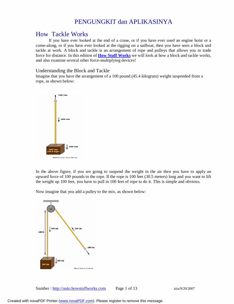
come-along, or if you have ever looked at the rigging on a sailboat, then you have seen a block and tackle at work. A block and tackle is an arrangement of rope and pulleys that allows you to trade force for distance. In this edition of How Stuff Works we will look at how a block and tackle works, and also examine several other force-multiplying devices! Understanding the Block and Tackle Imagine that you have the arrangement of a 100 pound (45.4 kilogram) weight suspended from a rope, as shown below:
In the above figure, if you are going to suspend the weight in the air then you have to apply an upward force of 100 pounds to the rope. If the rope is 100 feet (30.5 meters) long and you want to lift the weight up 100 feet, you have to pull in 100 feet of rope to do it. This is simple and obvious.
Now imagine that you add a pulley to the mix, as shown below:
Created with novaPDF Printer (www.novaPDF.com). Please register to remove this message.
Sumber : http://auto.howstuffworks.com Page 2 of 13 xtia/9/20/2007
Does this change anything? Not really. The only thing that changes is the direction of the force you have to apply to lift the weight. You still have to apply 100 pounds of force to keep the weight suspended, and you still have to reel in 100 feet of rope in order to lift the weight 100 feet.
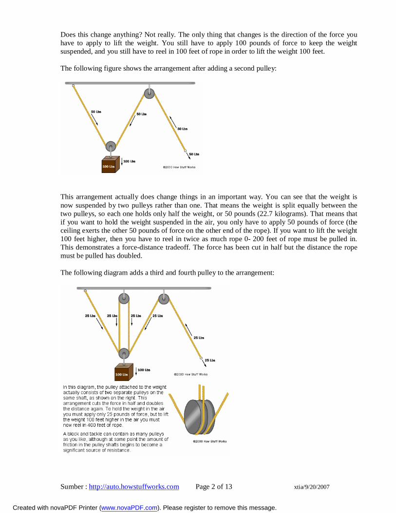
The following figure shows the arrangement after adding a second pulley:
This arrangement actually does change things in an important way. You can see that the weight is now suspended by two pulleys rather than one. That means the weight is split equally between the two pulleys, so each one holds only half the weight, or 50 pounds (22.7 kilograms). That means that if you want to hold the weight suspended in the air, you only have to apply 50 pounds of force (the ceiling exerts the other 50 pounds of force on the other end of the rope). If you want to lift the weight 100 feet higher, then you have to reel in twice as much rope 0- 200 feet of rope must be pulled in. This demonstrates a force-distance tradeoff. The force has been cut in half but the distance the rope must be pulled has doubled.
The following diagram adds a third and fourth pulley to the arrangement:
Created with novaPDF Printer (www.novaPDF.com). Please register to remove this message.
Sumber : http://auto.howstuffworks.com Page 3 of 13 xtia/9/20/2007
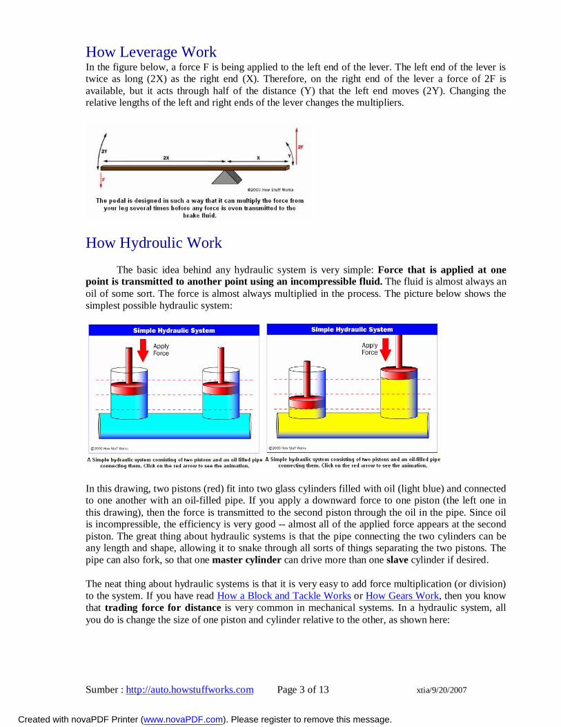
How Leverage Work In the figure below, a force F is being applied to the left end of the lever. The left end of the lever is twice as long (2X) as the right end (X). Therefore, on the right end of the lever a force of 2F is available, but it acts through half of the distance (Y) that the left end moves (2Y). Changing the relative lengths of the left and right ends of the lever changes the multipliers.
How Hydroulic Work
The basic idea behind any hydraulic system is very simple: Force that is applied at one point is transmitted to another point using an incompressible fluid. The fluid is almost always an oil of some sort. The force is almost always multiplied in the process. The picture below shows the simplest possible hydraulic system:
In this drawing, two pistons (red) fit into two glass cylinders filled with oil (light blue) and connected to one another with an oil-filled pipe. If you apply a downward force to one piston (the left one in this drawing), then the force is transmitted to the second piston through the oil in the pipe. Since oil is incompressible, the efficiency is very good -- almost all of the applied force appears at the second piston. The great thing about hydraulic systems is that the pipe connecting the two cylinders can be any length and shape, allowing it to snake through all sorts of things separating the two pistons. The pipe can also fork, so that one master cylinder can drive more than one slave cylinder if desired.
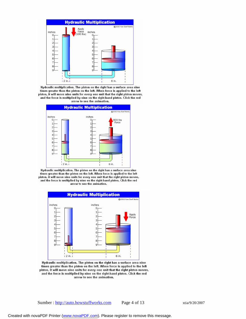
The neat thing about hydraulic systems is that it is very easy to add force multiplication (or division) to the system. If you have read How a Block and Tackle Works or How Gears Work, then you know that trading force for distance is very common in mechanical systems. In a hydraulic system, all you do is change the size of one piston and cylinder relative to the other, as shown here:
Created with novaPDF Printer (www.novaPDF.com). Please register to remove this message.
Sumber : http://auto.howstuffworks.com Page 4 of 13 xtia/9/20/2007
Created with novaPDF Printer (www.novaPDF.com). Please register to remove this message.
Sumber : http://auto.howstuffworks.com Page 5 of 13 xtia/9/20/2007
To determine the multiplication factor, start by looking at the size of the pistons. Assume that the piston on the left is 2 inches in diameter (1-inch radius), while the piston on the right is 6 inches in diameter (3-inch radius). The area of the two pistons is Pi * r2. The area of the left piston is therefore 3.14, while the area of the piston on the right is 28.26. The piston on the right is 9 times larger than the piston on the left. What that means is that any force applied to the left-hand piston will appear 9 times greater on the right-hand piston. So if you apply a 100-pound downward force to the left piston, a 900-pound upward force will appear on the right. The only catch is that you will have to depress the left piston 9 inches to raise the right piston 1 inch.
The brakes in your car are a good example of a basic piston-driven hydraulic system. When you depress the brake pedal in your car, it is pushing on the piston in the brake's master cylinder. Four slave pistons, one at each wheel, actuate to press the brake pads against the brake rotor to stop the car. (Actually, in almost all cars on the road today two master cylinders are driving two slave cylinders each. That way if one of the master cylinders has a problem or springs a leak, you can still stop the car.)
In most other hydraulic systems, hydraulic cylinders and pistons are connected through valves to a pump supplying high-pressure oil.
APLIKASINYA Simple Brake
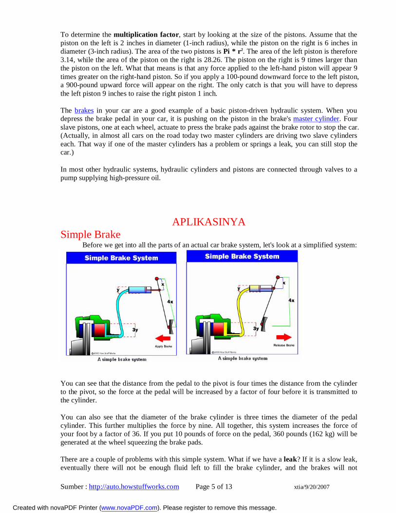
Before we get into all the parts of an actual car brake system, let's look at a simplified system:
You can see that the distance from the pedal to the pivot is four times the distance from the cylinder to the pivot, so the force at the pedal will be increased by a factor of four before it is transmitted to the cylinder.
You can also see that the diameter of the brake cylinder is three times the diameter of the pedal cylinder. This further multiplies the force by nine. All together, this system increases the force of your foot by a factor of 36. If you put 10 pounds of force on the pedal, 360 pounds (162 kg) will be generated at the wheel squeezing the brake pads.
There are a couple of problems with this simple system. What if we have a leak? If it is a slow leak, eventually there will not be enough fluid left to fill the brake cylinder, and the brakes will not
Created with novaPDF Printer (www.novaPDF.com). Please register to remove this message.
Sumber : http://auto.howstuffworks.com Page 6 of 13 xtia/9/20/2007
function. If it is a major leak, then the first time you apply the brakes all of the fluid will squirt out the leak and you will have complete brake failure.
The master cylinder on modern cars is designed to deal with these potential failures.
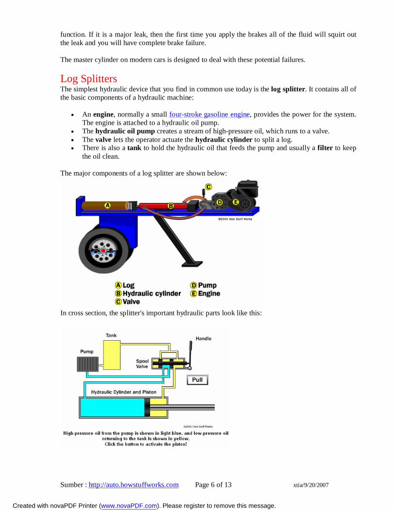
Log Splitters The simplest hydraulic device that you find in common use today is the log splitter. It contains all of the basic components of a hydraulic machine:
An engine, normally a small four-stroke gasoline engine, provides the power for the system. The engine is attached to a hydraulic oil pump.
The hydraulic oil pump creates a stream of high-pressure oil, which runs to a valve. The valve lets the operator actuate the hydraulic cylinder to split a log. There is also a tank to hold the hydraulic oil that feeds the pump and usually a filter to keep
the oil clean.
The major components of a log splitter are shown below:
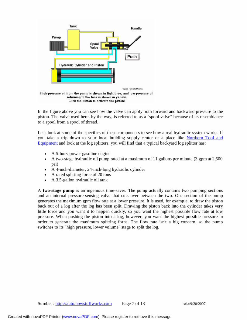
In cross section, the splitter's important hydraulic parts look like this:
Created with novaPDF Printer (www.novaPDF.com). Please register to remove this message.
Sumber : http://auto.howstuffworks.com Page 7 of 13 xtia/9/20/2007
In the figure above you can see how the valve can apply both forward and backward pressure to the piston. The valve used here, by the way, is referred to as a "spool valve" because of its resemblance to a spool from a spool of thread.
Let's look at some of the specifics of these components to see how a real hydraulic system works. If you take a trip down to your local building supply center or a place like Northern Tool and Equipment and look at the log splitters, you will find that a typical backyard log splitter has:
A 5-horsepower gasoline engine A two-stage hydraulic oil pump rated at a maximum of 11 gallons per minute (3 gpm at 2,500
psi) A 4-inch-diameter, 24-inch-long hydraulic cylinder A rated splitting force of 20 tons A 3.5-gallon hydraulic oil tank
A two-stage pump is an ingenious time-saver. The pump actually contains two pumping sections and an internal pressure-sensing valve that cuts over between the two. One section of the pump generates the maximum gpm flow rate at a lower pressure. It is used, for example, to draw the piston back out of a log after the log has been split. Drawing the piston back into the cylinder takes very little force and you want it to happen quickly, so you want the highest possible flow rate at low pressure. When pushing the piston into a log, however, you want the highest possible pressure in order to generate the maximum splitting force. The flow rate isn't a big concern, so the pump switches to its "high pressure, lower volume" stage to split the log.
Created with novaPDF Printer (www.novaPDF.com). Please register to remove this message.
Sumber : http://auto.howstuffworks.com Page 8 of 13 xtia/9/20/2007
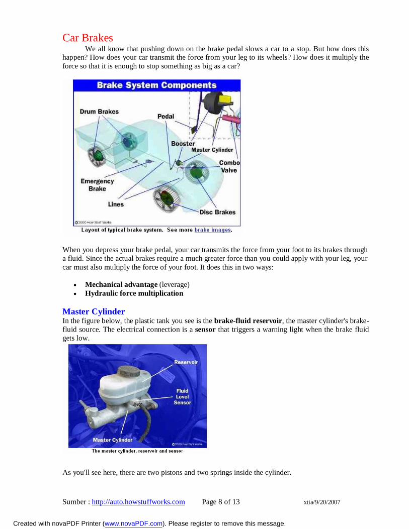
Car Brakes We all know that pushing down on the brake pedal slows a car to a stop. But how does this
happen? How does your car transmit the force from your leg to its wheels? How does it multiply the force so that it is enough to stop something as big as a car?
When you depress your brake pedal, your car transmits the force from your foot to its brakes through a fluid. Since the actual brakes require a much greater force than you could apply with your leg, your car must also multiply the force of your foot. It does this in two ways:
Mechanical advantage (leverage) Hydraulic force multiplication
Master Cylinder In the figure below, the plastic tank you see is the brake-fluid reservoir, the master cylinder's brake-fluid source. The electrical connection is a sensor that triggers a warning light when the brake fluid gets low.
As you'll see here, there are two pistons and two springs inside the cylinder.
Created with novaPDF Printer (www.novaPDF.com). Please register to remove this message.
Sumber : http://auto.howstuffworks.com Page 9 of 13 xtia/9/20/2007
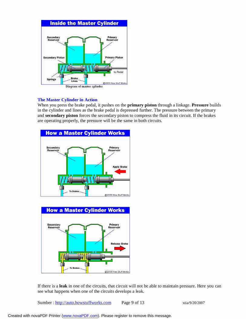
The Master Cylinder in Action When you press the brake pedal, it pushes on the primary piston through a linkage. Pressure builds in the cylinder and lines as the brake pedal is depressed further. The pressure between the primary and secondary piston forces the secondary piston to compress the fluid in its circuit. If the brakes are operating properly, the pressure will be the same in both circuits.
If there is a leak in one of the circuits, that circuit will not be able to maintain pressure. Here you can see what happens when one of the circuits develops a leak.
Created with novaPDF Printer (www.novaPDF.com). Please register to remove this message.
Sumber : http://auto.howstuffworks.com Page 10 of 13 xtia/9/20/2007
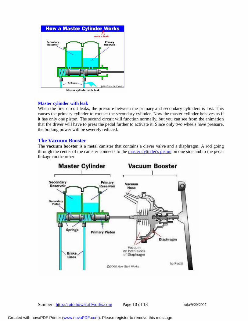
Master cylinder with leak When the first circuit leaks, the pressure between the primary and secondary cylinders is lost. This causes the primary cylinder to contact the secondary cylinder. Now the master cylinder behaves as if it has only one piston. The second circuit will function normally, but you can see from the animation that the driver will have to press the pedal further to activate it. Since only two wheels have pressure, the braking power will be severely reduced. The Vacuum Booster The vacuum booster is a metal canister that contains a clever valve and a diaphragm. A rod going through the center of the canister connects to the master cylinder's piston on one side and to the pedal linkage on the other.
Created with novaPDF Printer (www.novaPDF.com). Please register to remove this message.
Sumber : http://auto.howstuffworks.com Page 11 of 13 xtia/9/20/2007
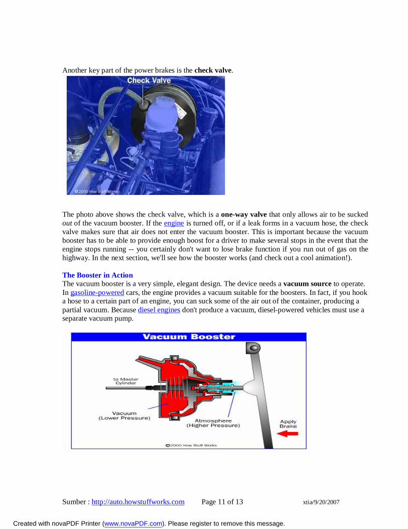
Another key part of the power brakes is the check valve.
The photo above shows the check valve, which is a one-way valve that only allows air to be sucked out of the vacuum booster. If the engine is turned off, or if a leak forms in a vacuum hose, the check valve makes sure that air does not enter the vacuum booster. This is important because the vacuum booster has to be able to provide enough boost for a driver to make several stops in the event that the engine stops running -- you certainly don't want to lose brake function if you run out of gas on the highway. In the next section, we'll see how the booster works (and check out a cool animation!). The Booster in Action The vacuum booster is a very simple, elegant design. The device needs a vacuum source to operate. In gasoline-powered cars, the engine provides a vacuum suitable for the boosters. In fact, if you hook a hose to a certain part of an engine, you can suck some of the air out of the container, producing a partial vacuum. Because diesel engines don't produce a vacuum, diesel-powered vehicles must use a separate vacuum pump.
Created with novaPDF Printer (www.novaPDF.com). Please register to remove this message.
Sumber : http://auto.howstuffworks.com Page 12 of 13 xtia/9/20/2007
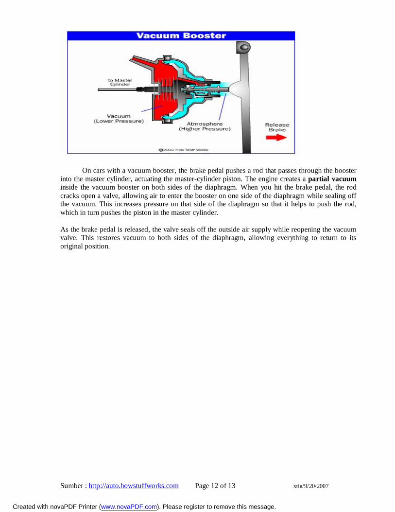
On cars with a vacuum booster, the brake pedal pushes a rod that passes through the booster
into the master cylinder, actuating the master-cylinder piston. The engine creates a partial vacuum inside the vacuum booster on both sides of the diaphragm. When you hit the brake pedal, the rod cracks open a valve, allowing air to enter the booster on one side of the diaphragm while sealing off the vacuum. This increases pressure on that side of the diaphragm so that it helps to push the rod, which in turn pushes the piston in the master cylinder.
As the brake pedal is released, the valve seals off the outside air supply while reopening the vacuum valve. This restores vacuum to both sides of the diaphragm, allowing everything to return to its original position.
Created with novaPDF Printer (www.novaPDF.com). Please register to remove this message.
Sumber : http://auto.howstuffworks.com Page 13 of 13 xtia/9/20/2007
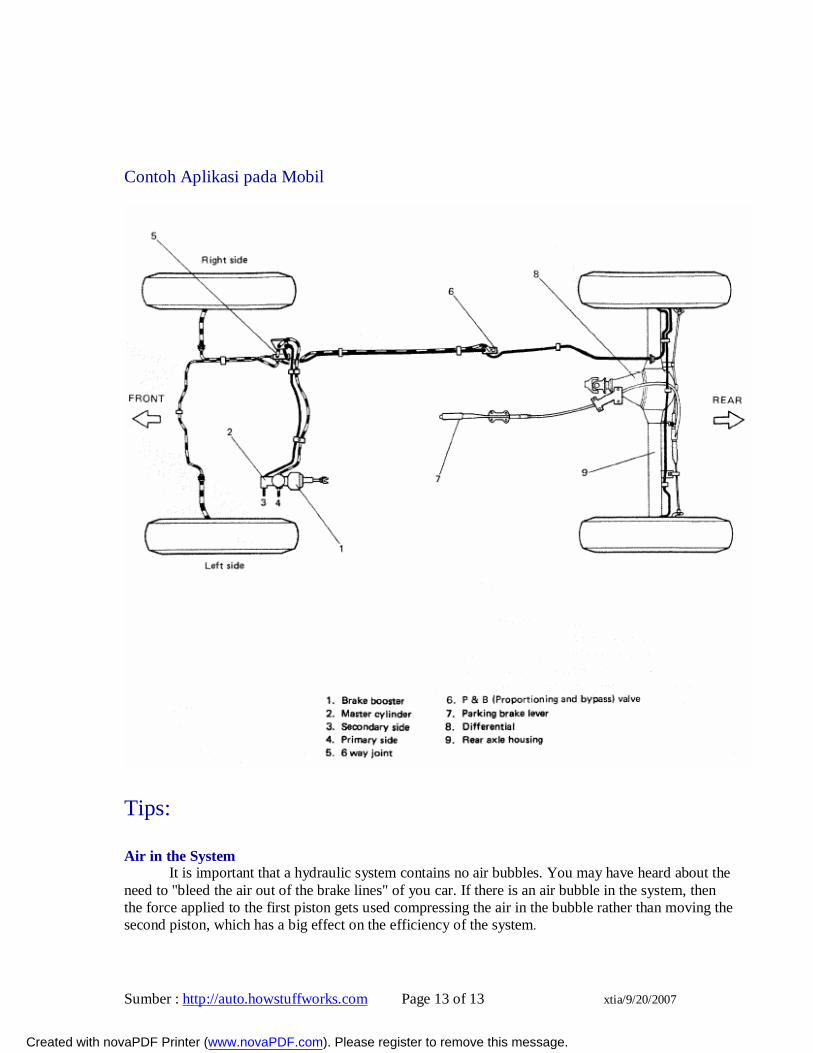
Contoh Aplikasi pada Mobil
Tips: Air in the System
It is important that a hydraulic system contains no air bubbles. You may have heard about the need to "bleed the air out of the brake lines" of you car. If there is an air bubble in the system, then the force applied to the first piston gets used compressing the air in the bubble rather than moving the second piston, which has a big effect on the efficiency of the system.
Created with novaPDF Printer (www.novaPDF.com). Please register to remove this message.