Embed Size (px)
Citation preview

— RELION® 670 SERIES
Phasor measurement unit RES670 Version 2.1 IEC Commissioning manual


Document ID: 1MRK 511 366-UENIssued: March 2019
Revision: AProduct version: 2.1
© Copyright 2016 ABB. All rights reserved

Copyright
This document and parts thereof must not be reproduced or copied without writtenpermission from ABB, and the contents thereof must not be imparted to a third party, norused for any unauthorized purpose.
The software and hardware described in this document is furnished under a license and maybe used or disclosed only in accordance with the terms of such license.
This product includes software developed by the OpenSSL Project for use in the OpenSSLToolkit. (http://www.openssl.org/) This product includes cryptographic software written/developed by: Eric Young ([email protected]) and Tim Hudson ([email protected]).
Trademarks
ABB and Relion are registered trademarks of the ABB Group. All other brand or product namesmentioned in this document may be trademarks or registered trademarks of their respectiveholders.
Warranty
Please inquire about the terms of warranty from your nearest ABB representative.

Disclaimer
The data, examples and diagrams in this manual are included solely for the concept or productdescription and are not to be deemed as a statement of guaranteed properties. All personsresponsible for applying the equipment addressed in this manual must satisfy themselves thateach intended application is suitable and acceptable, including that any applicable safety orother operational requirements are complied with. In particular, any risks in applications wherea system failure and/or product failure would create a risk for harm to property or persons(including but not limited to personal injuries or death) shall be the sole responsibility of theperson or entity applying the equipment, and those so responsible are hereby requested toensure that all measures are taken to exclude or mitigate such risks.
This document has been carefully checked by ABB but deviations cannot be completely ruledout. In case any errors are detected, the reader is kindly requested to notify the manufacturer.Other than under explicit contractual commitments, in no event shall ABB be responsible orliable for any loss or damage resulting from the use of this manual or the application of theequipment.

Conformity
This product complies with the directive of the Council of the European Communities on theapproximation of the laws of the Member States relating to electromagnetic compatibility(EMC Directive 2004/108/EC) and concerning electrical equipment for use within specifiedvoltage limits (Low-voltage directive 2006/95/EC). This conformity is the result of testsconducted by ABB in accordance with the product standard EN 60255-26 for the EMC directive,and with the product standards EN 60255-1 and EN 60255-27 for the low voltage directive. Theproduct is designed in accordance with the international standards of the IEC 60255 series.
Table of contents
Section 1 Introduction.........................................................................................................71.1 This manual......................................................................................................................................... 71.2 Intended audience..............................................................................................................................71.3 Product documentation................................................................................................................... 81.3.1 Product documentation set........................................................................................................ 81.3.2 Document revision history...........................................................................................................91.3.3 Related documents....................................................................................................................... 91.4 Document symbols and conventions...........................................................................................101.4.1 Symbols......................................................................................................................................... 101.4.2 Document conventions............................................................................................................... 111.5 IEC61850 edition 1 / edition 2 mapping.......................................................................................11
Section 2 Safety information........................................................................................... 192.1 Symbols on the product..................................................................................................................192.2 Warnings............................................................................................................................................ 192.3 Caution signs....................................................................................................................................202.4 Note signs..........................................................................................................................................21
Section 3 Available functions........................................................................................... 233.1 Wide area measurement functions.............................................................................................. 233.2 Back-up protection functions........................................................................................................233.3 Control and monitoring functions................................................................................................253.4 Communication................................................................................................................................293.5 Basic IED functions.......................................................................................................................... 31
Section 4 Starting up.........................................................................................................334.1 Factory and site acceptance testing............................................................................................334.2 Commissioning checklist............................................................................................................... 334.3 Checking the power supply............................................................................................................344.4 Energizing the IED........................................................................................................................... 344.4.1 Checking the IED operation.......................................................................................................344.4.2 IED start-up sequence................................................................................................................ 344.5 Setting up communication between PCM600 and the IED.....................................................354.6 Writing an application configuration to the IED....................................................................... 404.7 Checking CT circuits....................................................................................................................... 404.8 Checking VT circuits........................................................................................................................ 414.9 Using the RTXP test switch............................................................................................................414.10 Checking the binary I/O circuits................................................................................................... 424.10.1 Binary input circuits.................................................................................................................... 424.10.2 Binary output circuits................................................................................................................. 424.11 Checking optical connections....................................................................................................... 42
Table of contents
1Commissioning manual

Section 5 Configuring the IED and changing settings..................................................435.1 Overview............................................................................................................................................ 435.2 Configuring analog CT inputs....................................................................................................... 435.3 Reconfiguring the IED.....................................................................................................................44
Section 6 Establishing connection and verifying the SPA/IEC communication....... 456.1 Entering settings............................................................................................................................. 456.1.1 Entering SPA settings.................................................................................................................456.1.2 Entering IEC settings..................................................................................................................456.2 Verifying the communication........................................................................................................466.2.1 Verifying SPA communication.................................................................................................. 466.2.2 Verifying IEC communication................................................................................................... 466.3 fiber optic loop.................................................................................................................................466.4 Optical budget calculation for serial communication with SPA/IEC ....................................47
Section 7 Establishing connection and verifying the LON communication...............497.1 Communication via the rear ports .............................................................................................. 497.1.1 LON communication...................................................................................................................497.1.2 The LON Protocol........................................................................................................................ 507.1.3 Hardware and software modules............................................................................................ 507.2 Optical budget calculation for serial communication with LON ........................................... 51
Section 8 Establishing connection and verifying the IEC 61850 communication..... 538.1 Overview............................................................................................................................................ 538.2 Setting the station communication.............................................................................................538.3 Verifying the communication........................................................................................................54
Section 9 Establishing connection and verifying the IEEE C37.118/1344communication................................................................................................. 55
9.1 Overview............................................................................................................................................ 559.2 Setting the PMU station communication (PMU Report)..........................................................559.3 Setting the PMU station communication (PMU configuration)............................................. 559.4 Setting the TCP/UDP client communication............................................................................. 569.5 Verifying the communication........................................................................................................599.5.1 Verifying the IEEE C37.118/1344 TCP communication.........................................................599.5.2 Verifying the IEEE C37.118/1344 UDP communication........................................................ 659.6 Optical budget calculation for RES670 - PDC communication...............................................66
Section 10 Testing IED operation...................................................................................... 6710.1 Preparing for test.............................................................................................................................6710.1.1 Requirements............................................................................................................................... 6710.1.2 Preparing the IED to verify settings........................................................................................ 6810.2 Activating the test mode............................................................................................................... 6910.3 Preparing the connection to the test equipment..................................................................... 6910.4 Connecting the test equipment to the IED................................................................................ 7010.5 Releasing the function to be tested............................................................................................. 7110.6 Verifying analog primary and secondary measurement.......................................................... 72
Table of contents
2Commissioning manual

10.7 Testing the protection functionality............................................................................................7310.8 Forcing of binary I/O signals for testing.....................................................................................7310.8.1 Forcing concept........................................................................................................................... 7310.8.2 How to enable forcing................................................................................................................ 7410.8.2.1 Enable forcing by using LHMI................................................................................................ 7410.8.2.2 Enable forcing using TESTMODE function block...............................................................7410.8.3 How to change binary input/output signals using forcing................................................ 7410.8.3.1 Forcing by using LHMI.............................................................................................................7410.8.3.2 Forcing by using PCM600.......................................................................................................7610.8.4 How to undo forcing changes and return the IED to normal operation...........................7710.8.4.1 Undo forcing by using TestMode component....................................................................7810.8.4.2 Undo forcing by using LHMI...................................................................................................7810.8.4.3 Undo forcing by using PCM600.............................................................................................78
Section 11 Testing functionality by secondary injection............................................... 7911.1 Testing disturbance report............................................................................................................7911.1.1 Introduction..................................................................................................................................7911.1.2 Disturbance report settings......................................................................................................7911.1.3 Disturbance recorder (DR).........................................................................................................7911.1.4 Event recorder (ER) and Event list (EL)...................................................................................8011.2 Identifying the function to test in the technical reference manual ......................................8011.3 Impedance protection.................................................................................................................... 8011.3.1 Power swing detection ZMRPSB ............................................................................................. 8011.3.1.1 Verifying the settings.............................................................................................................. 8111.3.1.2 Testing the power swing detection function ZMRPSB ....................................................8211.3.1.3 Testing the tR1 timer...............................................................................................................8211.3.1.4 Testing the block input, interaction between FDPSPDIS or FRPSPDIS
and ZMRPSB ............................................................................................................................. 8311.3.1.5 Completing the test.................................................................................................................8311.3.2 Out-of-step protection OOSPPAM...........................................................................................8311.3.2.1 Verifying the settings..............................................................................................................8311.3.2.2 Test of point RE (RFwdR, XFwdX).............................................................................................. 87
11.3.2.3 Test of the boundary between zone 1 and zone 2, which is defined by theparameter ReachZ1.................................................................................................................. 91
11.3.2.4 Test of the point SE (RRvsR, XRvsX)......................................................................................... 94
11.4 Current protection...........................................................................................................................9911.4.1 Four step phase overcurrent protection 3-phase output OC4PTOC................................9911.4.1.1 Verifying the settings..............................................................................................................9911.4.1.2 Completing the test.............................................................................................................. 10011.4.2 Four step residual overcurrent protection, (Zero sequence or negative sequence
directionality) EF4PTOC ..........................................................................................................10011.4.2.1 Four step directional earth fault protection.................................................................... 10011.4.2.2 Four step non-directional earth fault protection.............................................................10111.4.2.3 Completing the test............................................................................................................... 10111.4.3 Four step negative sequence overcurrent protection NS4PTOC ....................................10111.4.3.1 Completing the test...............................................................................................................10211.4.4 Sensitive directional residual overcurrent and power protection SDEPSDE ................102
Table of contents
3Commissioning manual
11.4.4.1 Measuring the operate and time limit for set values......................................................10211.4.4.2 Completing the test.............................................................................................................. 10611.4.5 Thermal overload protection, one time constant, Celsius/Fahrenheit
LCPTTR/LFPTTR........................................................................................................................ 10611.4.5.1 Measuring the operate and time limit of set values....................................................... 10611.4.5.2 Completing the test...............................................................................................................10711.4.6 Directional underpower protection GUPPDUP ................................................................... 10711.4.6.1 Verifying the settings............................................................................................................ 10711.4.6.2 Completing the test.............................................................................................................. 10811.4.7 Directional overpower protection GOPPDOP ..................................................................... 10811.4.7.1 Verifying the settings............................................................................................................10811.4.7.2 Completing the test.............................................................................................................. 10911.5 Voltage protection........................................................................................................................ 10911.5.1 Two step undervoltage protection UV2PTUV .....................................................................10911.5.1.1 Verifying the settings............................................................................................................10911.5.1.2 Completing the test............................................................................................................... 11011.5.2 Two step overvoltage protection OV2PTOV ....................................................................... 11011.5.2.1 Verifying the settings............................................................................................................ 11011.5.2.2 Extended testing.....................................................................................................................11111.5.2.3 Completing the test................................................................................................................11111.6 Frequency protection.....................................................................................................................11111.6.1 Underfrequency protection SAPTUF ..................................................................................... 11111.6.1.1 Verifying the settings.............................................................................................................11111.6.1.2 Completing the test............................................................................................................... 11211.6.2 Overfrequency protection SAPTOF ....................................................................................... 11211.6.2.1 Verifying the settings.............................................................................................................11211.6.2.2 Completing the test............................................................................................................... 11311.6.3 Rate-of-change frequency protection SAPFRC ................................................................... 11311.6.3.1 Verifying the settings.............................................................................................................11311.6.3.2 Completing the test............................................................................................................... 11411.6.4 Frequency time accumulation protection function FTAQFVR.......................................... 11411.6.4.1 Verifying the settings............................................................................................................ 11411.6.4.2 Completing the test............................................................................................................... 11511.7 Multipurpose protection...............................................................................................................11511.7.1 General current and voltage protection CVGAPC................................................................11511.7.1.1 Built-in overcurrent feature (non-directional).................................................................. 11611.7.1.2 Overcurrent feature with current restraint....................................................................... 11611.7.1.3 Overcurrent feature with voltage restraint....................................................................... 11611.7.1.4 Overcurrent feature with directionality............................................................................. 11711.7.1.5 Over/Undervoltage feature.................................................................................................. 11711.7.1.6 Completing the test............................................................................................................... 11811.8 Secondary system supervision.................................................................................................... 11811.8.1 Current circuit supervision CCSSPVC.................................................................................... 11811.8.1.1 Verifying the settings............................................................................................................ 11811.8.1.2 Completing the test............................................................................................................... 11811.8.2 Fuse failure supervision FUFSPVC..........................................................................................118
Table of contents
4Commissioning manual

11.8.2.1 Checking that the binary inputs and outputs operate as expected ........................... 11811.8.2.2 Measuring the operate value for the negative sequence function ..............................11911.8.2.3 Measuring the operate value for the zero-sequence function .....................................12011.8.2.4 Measuring the operate value for the dead line detection function............................. 12011.8.2.5 Checking the operation of the du/dt and di/dt based function ................................. 12111.8.2.6 Completing the test............................................................................................................... 12111.9 Control..............................................................................................................................................12211.9.1 Single command, 16 signals SINGLECMD............................................................................. 12211.10 Logic..................................................................................................................................................12211.10.1 Tripping logic, common 3-phase output SMPPTRC ...........................................................12211.10.1.1 Three-phase operating mode.............................................................................................. 12211.10.1.2 1ph/3ph operating mode......................................................................................................12211.10.1.3 1ph/2ph/3ph operating mode.............................................................................................12311.10.1.4 Circuit breaker lockout..........................................................................................................12411.10.1.5 Completing the test...............................................................................................................12411.11 Monitoring....................................................................................................................................... 12511.11.1 Gas medium supervision SSIMG............................................................................................. 12511.11.1.1 Testing the liquid medium supervision for alarm and lock out conditions................12511.11.1.2 Completing the test...............................................................................................................12511.11.2 Liquid medium supervision SSIML......................................................................................... 12511.11.2.1 Testing the liquid medium supervision for alarm and lock out conditions................12511.11.2.2 Completing the test...............................................................................................................12611.11.3 Breaker monitoring SSCBR...................................................................................................... 12611.11.3.1 Verifying the settings............................................................................................................ 12611.11.3.2 Completing the test............................................................................................................... 12711.11.4 Event function EVENT............................................................................................................... 12711.11.5 Limit counter L4UFCNT............................................................................................................ 12811.11.5.1 Completing the test...............................................................................................................12811.12 Metering...........................................................................................................................................12811.12.1 Pulse-counter logic PCFCNT....................................................................................................12811.12.2 Function for energy calculation and demand handling ETPMMTR..................................12811.12.2.1 Verifying the settings............................................................................................................ 12811.12.2.2 Completing the test...............................................................................................................12911.13 Station communication................................................................................................................ 13011.13.1 Multiple command and transmit MULTICMDRCV / MULTICMDSND.............................. 13011.14 Remote communication............................................................................................................... 13011.14.1 Binary signal transfer BinSignReceive, BinSignTransm.....................................................13011.15 Basic IED functions.........................................................................................................................13111.15.1 Parameter setting group handling SETGRPS....................................................................... 13111.15.1.1 Verifying the settings.............................................................................................................13111.15.1.2 Completing the test............................................................................................................... 13111.16 Exit test mode.................................................................................................................................132
Section 12 Commissioning and maintenance of the fault clearing system............... 13312.1 Commissioning tests.................................................................................................................... 13312.2 Periodic maintenance tests......................................................................................................... 133
Table of contents
5Commissioning manual

12.2.1 Visual inspection........................................................................................................................13412.2.2 Maintenance tests..................................................................................................................... 13412.2.2.1 Preparation..............................................................................................................................13412.2.2.2 Recording.................................................................................................................................13412.2.2.3 Secondary injection............................................................................................................... 13412.2.2.4 Alarm test.................................................................................................................................13512.2.2.5 Self supervision check........................................................................................................... 13512.2.2.6 Trip circuit check.................................................................................................................... 13512.2.2.7 Measurement of service currents....................................................................................... 13512.2.2.8 Restoring..................................................................................................................................136
Section 13 Troubleshooting..............................................................................................13713.1 Checking the self supervision signals........................................................................................ 13713.1.1 Checking the self supervision function................................................................................. 13713.1.1.1 Determine the cause of an internal failure........................................................................ 13713.1.2 Self supervision HMI data.........................................................................................................13713.1.2.1 General IED status.................................................................................................................. 13713.1.2.2 Communication Diagnostics............................................................................................... 13813.2 Fault tracing.................................................................................................................................... 14313.2.1 Internal fault indications.......................................................................................................... 14313.2.2 Using front-connected PC....................................................................................................... 14413.2.3 Diagnosing the IED status via the LHMI hint menu............................................................14513.2.4 Hardware re-configuration...................................................................................................... 14713.3 Repair instruction.......................................................................................................................... 14813.4 Repair support................................................................................................................................14913.5 Maintenance....................................................................................................................................149
Section 14 Glossary............................................................................................................151
Table of contents
6Commissioning manual

Section 1 Introduction
1.1 This manualGUID-AB423A30-13C2-46AF-B7FE-A73BB425EB5F v19
The commissioning manual contains instructions on how to commission the IED. The manualcan also be used by system engineers and maintenance personnel for assistance during thetesting phase. The manual provides procedures for the checking of external circuitry andenergizing the IED, parameter setting and configuration as well as verifying settings bysecondary injection. The manual describes the process of testing an IED in a substation whichis not in service. The chapters are organized in the chronological order in which the IED shouldbe commissioned. The relevant procedures may be followed also during the service andmaintenance activities.
1.2 Intended audienceGUID-C9B8127F-5748-4BEA-9E4F-CC762FE28A3A v10
This manual addresses the personnel responsible for commissioning, maintenance and takingthe IED in and out of normal service.
The commissioning personnel must have a basic knowledge of handling electronic equipment.The commissioning and maintenance personnel must be well experienced in using protectionequipment, test equipment, protection functions and the configured functional logics in theIED.
1MRK 511 366-UEN A Section 1Introduction
7Commissioning manual
1.3 Product documentation
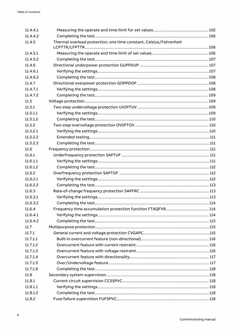
1.3.1 Product documentation setGUID-3AA69EA6-F1D8-47C6-A8E6-562F29C67172 v15
IEC07000220-4-en.vsd
Plan
ning
& p
urch
ase
Engi
neer
ing
Inst
allin
g
Com
mis
sion
ing
Ope
ratio
n
Mai
nten
ance
Dec
omm
issi
onin
gD
eins
tallin
g &
disp
osal
Application manual
Operation manual
Installation manual
Engineering manual
Communication protocol manual
Cyber security deployment guideline
Technical manual
Commissioning manual
IEC07000220 V4 EN-US
Figure 1: The intended use of manuals throughout the product lifecycle
The engineering manual contains instructions on how to engineer the IEDs using the varioustools available within the PCM600 software. The manual provides instructions on how to setup a PCM600 project and insert IEDs to the project structure. The manual also recommends asequence for the engineering of protection and control functions, LHMI functions as well ascommunication engineering for IEC 60870-5-103, IEC 61850, DNP3, LON and SPA.
The installation manual contains instructions on how to install the IED. The manual providesprocedures for mechanical and electrical installation. The chapters are organized in thechronological order in which the IED should be installed.
The commissioning manual contains instructions on how to commission the IED. The manualcan also be used by system engineers and maintenance personnel for assistance during thetesting phase. The manual provides procedures for the checking of external circuitry andenergizing the IED, parameter setting and configuration as well as verifying settings bysecondary injection. The manual describes the process of testing an IED in a substation whichis not in service. The chapters are organized in the chronological order in which the IED shouldbe commissioned. The relevant procedures may be followed also during the service andmaintenance activities.
The operation manual contains instructions on how to operate the IED once it has beencommissioned. The manual provides instructions for the monitoring, controlling and setting ofthe IED. The manual also describes how to identify disturbances and how to view calculatedand measured power grid data to determine the cause of a fault.
Section 1 1MRK 511 366-UEN AIntroduction
8Commissioning manual
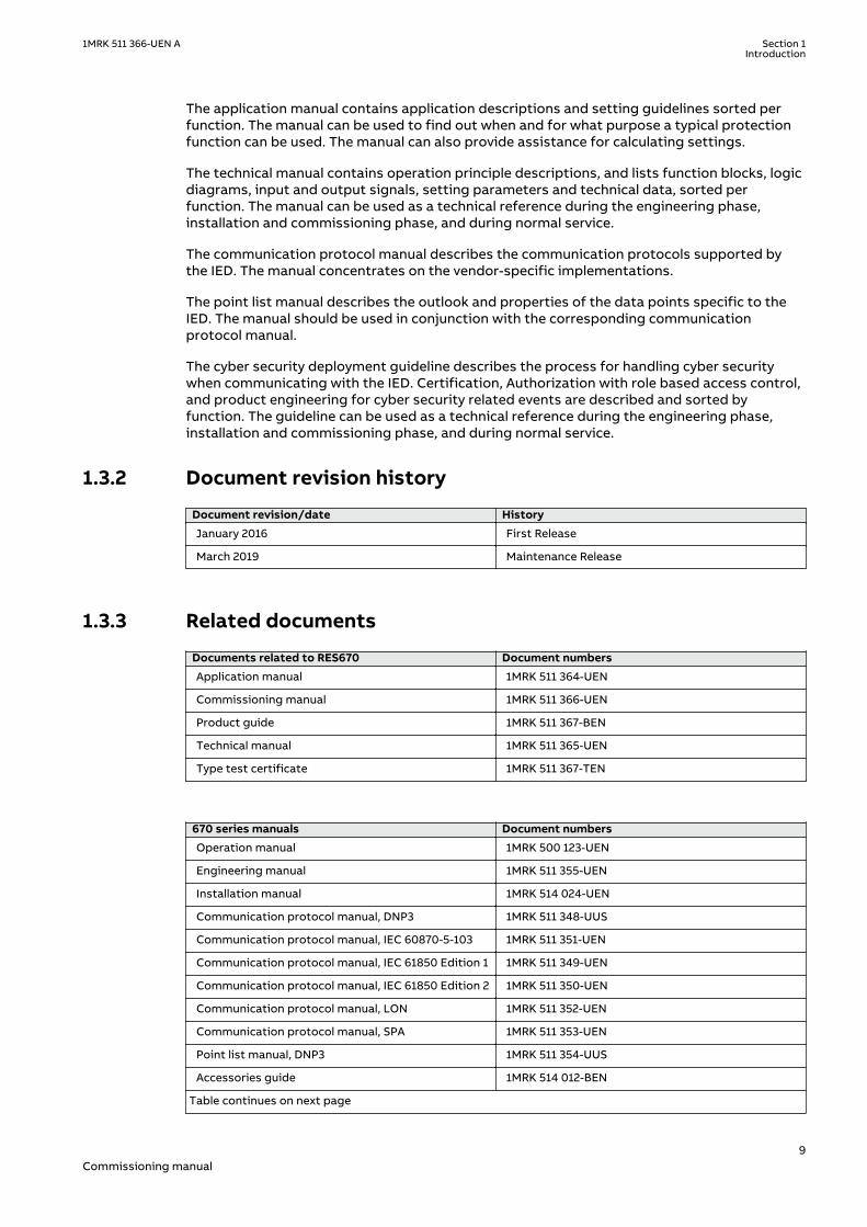
The application manual contains application descriptions and setting guidelines sorted perfunction. The manual can be used to find out when and for what purpose a typical protectionfunction can be used. The manual can also provide assistance for calculating settings.
The technical manual contains operation principle descriptions, and lists function blocks, logicdiagrams, input and output signals, setting parameters and technical data, sorted perfunction. The manual can be used as a technical reference during the engineering phase,installation and commissioning phase, and during normal service.
The communication protocol manual describes the communication protocols supported bythe IED. The manual concentrates on the vendor-specific implementations.
The point list manual describes the outlook and properties of the data points specific to theIED. The manual should be used in conjunction with the corresponding communicationprotocol manual.
The cyber security deployment guideline describes the process for handling cyber securitywhen communicating with the IED. Certification, Authorization with role based access control,and product engineering for cyber security related events are described and sorted byfunction. The guideline can be used as a technical reference during the engineering phase,installation and commissioning phase, and during normal service.
1.3.2 Document revision historyGUID-C8027F8A-D3CB-41C1-B078-F9E59BB73A6C v2.1.1
Document revision/date History
January 2016 First Release
March 2019 Maintenance Release
1.3.3 Related documentsGUID-94E8A5CA-BE1B-45AF-81E7-5A41D34EE112 v4
Documents related to RES670 Document numbers
Application manual 1MRK 511 364-UEN
Commissioning manual 1MRK 511 366-UEN
Product guide 1MRK 511 367-BEN
Technical manual 1MRK 511 365-UEN
Type test certificate 1MRK 511 367-TEN
670 series manuals Document numbers
Operation manual 1MRK 500 123-UEN
Engineering manual 1MRK 511 355-UEN
Installation manual 1MRK 514 024-UEN
Communication protocol manual, DNP3 1MRK 511 348-UUS
Communication protocol manual, IEC 60870-5-103 1MRK 511 351-UEN
Communication protocol manual, IEC 61850 Edition 1 1MRK 511 349-UEN
Communication protocol manual, IEC 61850 Edition 2 1MRK 511 350-UEN
Communication protocol manual, LON 1MRK 511 352-UEN
Communication protocol manual, SPA 1MRK 511 353-UEN
Point list manual, DNP3 1MRK 511 354-UUS
Accessories guide 1MRK 514 012-BEN
Table continues on next page
1MRK 511 366-UEN A Section 1Introduction
9Commissioning manual

670 series manuals Document numbers
Cyber security deployment guideline 1MRK 511 356-UEN
Connection and Installation components 1MRK 513 003-BEN
Test system, COMBITEST 1MRK 512 001-BEN
1.4 Document symbols and conventions
1.4.1 SymbolsGUID-2945B229-DAB0-4F15-8A0E-B9CF0C2C7B15 v12
The electrical warning icon indicates the presence of a hazard which couldresult in electrical shock.
The warning icon indicates the presence of a hazard which could result inpersonal injury.
The caution hot surface icon indicates important information or warning aboutthe temperature of product surfaces.
Class 1 Laser product. Take adequate measures to protect the eyes and do notview directly with optical instruments.
The caution icon indicates important information or warning related to theconcept discussed in the text. It might indicate the presence of a hazard whichcould result in corruption of software or damage to equipment or property.
The information icon alerts the reader of important facts and conditions.
The tip icon indicates advice on, for example, how to design your project orhow to use a certain function.
Although warning hazards are related to personal injury, it is necessary to understand thatunder certain operational conditions, operation of damaged equipment may result indegraded process performance leading to personal injury or death. It is important that theuser fully complies with all warning and cautionary notices.
Section 1 1MRK 511 366-UEN AIntroduction
10Commissioning manual
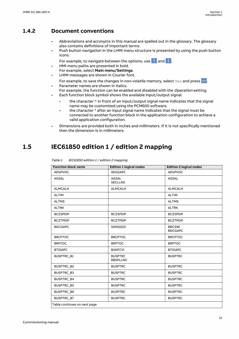
1.4.2 Document conventionsGUID-96DFAB1A-98FE-4B26-8E90-F7CEB14B1AB6 v8
• Abbreviations and acronyms in this manual are spelled out in the glossary. The glossaryalso contains definitions of important terms.
• Push button navigation in the LHMI menu structure is presented by using the push buttonicons.
For example, to navigate between the options, use and .• HMI menu paths are presented in bold.
For example, select Main menu/Settings.• LHMI messages are shown in Courier font.
For example, to save the changes in non-volatile memory, select Yes and press .• Parameter names are shown in italics.
For example, the function can be enabled and disabled with the Operation setting.• Each function block symbol shows the available input/output signal.
• the character ^ in front of an input/output signal name indicates that the signalname may be customized using the PCM600 software.
• the character * after an input signal name indicates that the signal must beconnected to another function block in the application configuration to achieve avalid application configuration.
• Dimensions are provided both in inches and millimeters. If it is not specifically mentionedthen the dimension is in millimeters.
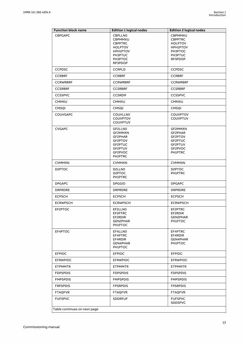
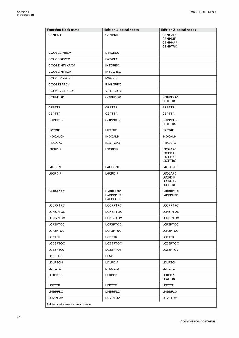
1.5 IEC61850 edition 1 / edition 2 mappingGUID-C5133366-7260-4C47-A975-7DBAB3A33A96 v2
Table 1: IEC61850 edition 1 / edition 2 mapping
Function block name Edition 1 logical nodes Edition 2 logical nodes
AEGPVOC AEGGAPC AEGPVOC
AGSAL AGSALSECLLN0
AGSAL
ALMCALH ALMCALH ALMCALH
ALTIM ALTIM
ALTMS ALTMS
ALTRK ALTRK
BCZSPDIF BCZSPDIF BCZSPDIF
BCZTPDIF BCZTPDIF BCZTPDIF
BDCGAPC SWSGGIO BBCSWIBDCGAPC
BRCPTOC BRCPTOC BRCPTOC
BRPTOC BRPTOC BRPTOC
BTIGAPC B16IFCVI BTIGAPC
BUSPTRC_B1 BUSPTRCBBSPLLN0
BUSPTRC
BUSPTRC_B2 BUSPTRC BUSPTRC
BUSPTRC_B3 BUSPTRC BUSPTRC
BUSPTRC_B4 BUSPTRC BUSPTRC
BUSPTRC_B5 BUSPTRC BUSPTRC
BUSPTRC_B6 BUSPTRC BUSPTRC
BUSPTRC_B7 BUSPTRC BUSPTRC
Table continues on next page
1MRK 511 366-UEN A Section 1Introduction
11Commissioning manual

Function block name Edition 1 logical nodes Edition 2 logical nodes
BUSPTRC_B8 BUSPTRC BUSPTRC
BUSPTRC_B9 BUSPTRC BUSPTRC
BUSPTRC_B10 BUSPTRC BUSPTRC
BUSPTRC_B11 BUSPTRC BUSPTRC
BUSPTRC_B12 BUSPTRC BUSPTRC
BUSPTRC_B13 BUSPTRC BUSPTRC
BUSPTRC_B14 BUSPTRC BUSPTRC
BUSPTRC_B15 BUSPTRC BUSPTRC
BUSPTRC_B16 BUSPTRC BUSPTRC
BUSPTRC_B17 BUSPTRC BUSPTRC
BUSPTRC_B18 BUSPTRC BUSPTRC
BUSPTRC_B19 BUSPTRC BUSPTRC
BUSPTRC_B20 BUSPTRC BUSPTRC
BUSPTRC_B21 BUSPTRC BUSPTRC
BUSPTRC_B22 BUSPTRC BUSPTRC
BUSPTRC_B23 BUSPTRC BUSPTRC
BUSPTRC_B24 BUSPTRC BUSPTRC
BUTPTRC_B1 BUTPTRCBBTPLLN0
BUTPTRC
BUTPTRC_B2 BUTPTRC BUTPTRC
BUTPTRC_B3 BUTPTRC BUTPTRC
BUTPTRC_B4 BUTPTRC BUTPTRC
BUTPTRC_B5 BUTPTRC BUTPTRC
BUTPTRC_B6 BUTPTRC BUTPTRC
BUTPTRC_B7 BUTPTRC BUTPTRC
BUTPTRC_B8 BUTPTRC BUTPTRC
BZISGGIO BZISGGIO BZISGAPC
BZITGGIO BZITGGIO BZITGAPC
BZNSPDIF_A BZNSPDIF BZASGAPCBZASPDIFBZNSGAPCBZNSPDIF
BZNSPDIF_B BZNSPDIF BZBSGAPCBZBSPDIFBZNSGAPCBZNSPDIF
BZNTPDIF_A BZNTPDIF BZATGAPCBZATPDIFBZNTGAPCBZNTPDIF
BZNTPDIF_B BZNTPDIF BZBTGAPCBZBTPDIFBZNTGAPCBZNTPDIF
Table continues on next page
Section 1 1MRK 511 366-UEN AIntroduction
12Commissioning manual
Function block name Edition 1 logical nodes Edition 2 logical nodes
CBPGAPC CBPLLN0CBPMMXUCBPPTRCHOLPTOVHPH1PTOVPH3PTUCPH3PTOCRP3PDOP
CBPMMXUCBPPTRCHOLPTOVHPH1PTOVPH3PTOCPH3PTUCRP3PDOP
CCPDSC CCRPLD CCPDSC
CCRBRF CCRBRF CCRBRF
CCRWRBRF CCRWRBRF CCRWRBRF
CCSRBRF CCSRBRF CCSRBRF
CCSSPVC CCSRDIF CCSSPVC
CMMXU CMMXU CMMXU
CMSQI CMSQI CMSQI
COUVGAPC COUVLLN0COUVPTOVCOUVPTUV
COUVPTOVCOUVPTUV
CVGAPC GF2LLN0GF2MMXNGF2PHARGF2PTOVGF2PTUCGF2PTUVGF2PVOCPH1PTRC
GF2MMXNGF2PHARGF2PTOVGF2PTUCGF2PTUVGF2PVOCPH1PTRC
CVMMXN CVMMXN CVMMXN
D2PTOC D2LLN0D2PTOCPH1PTRC
D2PTOCPH1PTRC
DPGAPC DPGGIO DPGAPC
DRPRDRE DRPRDRE DRPRDRE
ECPSCH ECPSCH ECPSCH
ECRWPSCH ECRWPSCH ECRWPSCH
EF2PTOC EF2LLN0EF2PTRCEF2RDIRGEN2PHARPH1PTOC
EF2PTRCEF2RDIRGEN2PHARPH1PTOC
EF4PTOC EF4LLN0EF4PTRCEF4RDIRGEN4PHARPH1PTOC
EF4PTRCEF4RDIRGEN4PHARPH1PTOC
EFPIOC EFPIOC EFPIOC
EFRWPIOC EFRWPIOC EFRWPIOC
ETPMMTR ETPMMTR ETPMMTR
FDPSPDIS FDPSPDIS FDPSPDIS
FMPSPDIS FMPSPDIS FMPSPDIS
FRPSPDIS FPSRPDIS FPSRPDIS
FTAQFVR FTAQFVR FTAQFVR
FUFSPVC SDDRFUF FUFSPVCSDDSPVC
Table continues on next page
1MRK 511 366-UEN A Section 1Introduction
13Commissioning manual
Function block name Edition 1 logical nodes Edition 2 logical nodes
GENPDIF GENPDIF GENGAPCGENPDIFGENPHARGENPTRC
GOOSEBINRCV BINGREC
GOOSEDPRCV DPGREC
GOOSEINTLKRCV INTGREC
GOOSEINTRCV INTSGREC
GOOSEMVRCV MVGREC
GOOSESPRCV BINSGREC
GOOSEVCTRRCV VCTRGREC
GOPPDOP GOPPDOP GOPPDOPPH1PTRC
GRPTTR GRPTTR GRPTTR
GSPTTR GSPTTR GSPTTR
GUPPDUP GUPPDUP GUPPDUPPH1PTRC
HZPDIF HZPDIF HZPDIF
INDCALCH INDCALH INDCALH
ITBGAPC IB16FCVB ITBGAPC
L3CPDIF L3CPDIF L3CGAPCL3CPDIFL3CPHARL3CPTRC
L4UFCNT L4UFCNT L4UFCNT
L6CPDIF L6CPDIF L6CGAPCL6CPDIFL6CPHARL6CPTRC
LAPPGAPC LAPPLLN0LAPPPDUPLAPPPUPF
LAPPPDUPLAPPPUPF
LCCRPTRC LCCRPTRC LCCRPTRC
LCNSPTOC LCNSPTOC LCNSPTOC
LCNSPTOV LCNSPTOV LCNSPTOV
LCP3PTOC LCP3PTOC LCP3PTOC
LCP3PTUC LCP3PTUC LCP3PTUC
LCPTTR LCPTTR LCPTTR
LCZSPTOC LCZSPTOC LCZSPTOC
LCZSPTOV LCZSPTOV LCZSPTOV
LD0LLN0 LLN0
LDLPSCH LDLPDIF LDLPSCH
LDRGFC STSGGIO LDRGFC
LEXPDIS LEXPDIS LEXPDISLEXPTRC
LFPTTR LFPTTR LFPTTR
LMBRFLO LMBRFLO LMBRFLO
LOVPTUV LOVPTUV LOVPTUV
Table continues on next page
Section 1 1MRK 511 366-UEN AIntroduction
14Commissioning manual

Function block name Edition 1 logical nodes Edition 2 logical nodes
LPHD LPHD
LPTTR LPTTR LPTTR
LT3CPDIF LT3CPDIF LT3CGAPCLT3CPDIFLT3CPHARLT3CPTRC
LT6CPDIF LT6CPDIF LT6CGAPCLT6CPDIFLT6CPHARLT6CPTRC
MVGAPC MVGGIO MVGAPC
NS2PTOC NS2LLN0NS2PTOCNS2PTRC
NS2PTOCNS2PTRC
NS4PTOC EF4LLN0EF4PTRCEF4RDIRGEN4PHARPH1PTOC
EF4PTRCEF4RDIRPH1PTOC
O2RWPTOV GEN2LLN0O2RWPTOVPH1PTRC
O2RWPTOVPH1PTRC
OC4PTOC OC4LLN0GEN4PHARPH3PTOCPH3PTRC
GEN4PHARPH3PTOCPH3PTRC
OEXPVPH OEXPVPH OEXPVPH
OOSPPAM OOSPPAM OOSPPAMOOSPTRC
OV2PTOV GEN2LLN0OV2PTOVPH1PTRC
OV2PTOVPH1PTRC
PAPGAPC PAPGAPC PAPGAPC
PCFCNT PCGGIO PCFCNT
PH4SPTOC GEN4PHAROCNDLLN0PH1BPTOCPH1PTRC
GEN4PHARPH1BPTOCPH1PTRC
PHPIOC PHPIOC PHPIOC
PRPSTATUS RCHLCCH RCHLCCHSCHLCCH
PSLPSCH ZMRPSL PSLPSCH
PSPPPAM PSPPPAM PSPPPAMPSPPTRC
QCBAY QCBAY
QCRSV QCRSV QCRSV
REFPDIF REFPDIF REFPDIF
ROTIPHIZ ROTIPHIZ ROTIPHIZROTIPTRC
ROV2PTOV GEN2LLN0PH1PTRCROV2PTOV
PH1PTRCROV2PTOV
SAPFRC SAPFRC SAPFRC
Table continues on next page
1MRK 511 366-UEN A Section 1Introduction
15Commissioning manual

Function block name Edition 1 logical nodes Edition 2 logical nodes
SAPTOF SAPTOF SAPTOF
SAPTUF SAPTUF SAPTUF
SCCVPTOC SCCVPTOC SCCVPTOC
SCILO SCILO SCILO
SCSWI SCSWI SCSWI
SDEPSDE SDEPSDE SDEPSDESDEPTOCSDEPTOVSDEPTRC
SESRSYN RSY1LLN0AUT1RSYNMAN1RSYNSYNRSYN
AUT1RSYNMAN1RSYNSYNRSYN
SINGLELCCH SCHLCCH
SLGAPC SLGGIO SLGAPC
SMBRREC SMBRREC SMBRREC
SMPPTRC SMPPTRC SMPPTRC
SP16GAPC SP16GGIO SP16GAPC
SPC8GAPC SPC8GGIO SPC8GAPC
SPGAPC SPGGIO SPGAPC
SSCBR SSCBR SSCBR
SSIMG SSIMG SSIMG
SSIML SSIML SSIML
STBPTOC STBPTOC BBPMSSSTBPTOC
STEFPHIZ STEFPHIZ STEFPHIZ
STTIPHIZ STTIPHIZ STTIPHIZ
SXCBR SXCBR SXCBR
SXSWI SXSWI SXSWI
T2WPDIF T2WPDIF T2WGAPCT2WPDIFT2WPHART2WPTRC
T3WPDIF T3WPDIF T3WGAPCT3WPDIFT3WPHART3WPTRC
TCLYLTC TCLYLTC TCLYLTCTCSLTC
TCMYLTC TCMYLTC TCMYLTC
TEIGAPC TEIGGIO TEIGAPCTEIGGIO
TEILGAPC TEILGGIO TEILGAPC
TMAGAPC TMAGGIO TMAGAPC
TPPIOC TPPIOC TPPIOC
TR1ATCC TR1ATCC TR1ATCC
TR8ATCC TR8ATCC TR8ATCC
TRPTTR TRPTTR TRPTTR
Table continues on next page
Section 1 1MRK 511 366-UEN AIntroduction
16Commissioning manual

Function block name Edition 1 logical nodes Edition 2 logical nodes
U2RWPTUV GEN2LLN0PH1PTRCU2RWPTUV
PH1PTRCU2RWPTUV
UV2PTUV GEN2LLN0PH1PTRCUV2PTUV
PH1PTRCUV2PTUV
VDCPTOV VDCPTOV VDCPTOV
VDSPVC VDRFUF VDSPVC
VMMXU VMMXU VMMXU
VMSQI VMSQI VMSQI
VNMMXU VNMMXU VNMMXU
VRPVOC VRLLN0PH1PTRCPH1PTUVVRPVOC
PH1PTRCPH1PTUVVRPVOC
VSGAPC VSGGIO VSGAPC
WRNCALH WRNCALH WRNCALH
ZC1PPSCH ZPCPSCH ZPCPSCH
ZC1WPSCH ZPCWPSCH ZPCWPSCH
ZCLCPSCH ZCLCPLAL ZCLCPSCH
ZCPSCH ZCPSCH ZCPSCH
ZCRWPSCH ZCRWPSCH ZCRWPSCH
ZCVPSOF ZCVPSOF ZCVPSOF
ZGVPDIS ZGVLLN0PH1PTRCZGVPDISZGVPTUV
PH1PTRCZGVPDISZGVPTUV
ZMCAPDIS ZMCAPDIS ZMCAPDIS
ZMCPDIS ZMCPDIS ZMCPDIS
ZMFCPDIS ZMFCLLN0PSFPDISZMFPDISZMFPTRCZMMMXU
PSFPDISZMFPDISZMFPTRCZMMMXU
ZMFPDIS ZMFLLN0PSFPDISZMFPDISZMFPTRCZMMMXU
PSFPDISPSFPDISZMFPDISZMFPTRCZMMMXU
ZMHPDIS ZMHPDIS ZMHPDIS
ZMMAPDIS ZMMAPDIS ZMMAPDIS
ZMMPDIS ZMMPDIS ZMMPDIS
ZMQAPDIS ZMQAPDIS ZMQAPDIS
ZMQPDIS ZMQPDIS ZMQPDIS
ZMRAPDIS ZMRAPDIS ZMRAPDIS
ZMRPDIS ZMRPDIS ZMRPDIS
ZMRPSB ZMRPSB ZMRPSB
ZSMGAPC ZSMGAPC ZSMGAPC
1MRK 511 366-UEN A Section 1Introduction
17Commissioning manual

18

Section 2 Safety information
2.1 Symbols on the productGUID-E48F2EC3-6AB8-4ECF-A77E-F16CE45CA5FD v2
All warnings must be observed.
Read the entire manual before doing installation or any maintenance work onthe product. All warnings must be observed.
Class 1 Laser product. Take adequate measures to protect your eyes and do notview directly with optical instruments.
Do not touch the unit in operation. The installation shall take into account theworst case temperature.
2.2 WarningsIP1504-1 v2
Observe the warnings during all types of work related to the product.GUID-C9B6638A-57E7-4E05-9A33-A60E359C54AF v1
Only electrically skilled persons with the proper authorization and knowledge ofany safety hazards are allowed to carry out the electrical installation.
M2366-2 v2
National and local electrical safety regulations must always be followed.Working in a high voltage environment requires serious approach to avoidhuman injuries and damage to equipment.
M2362-2 v1
Do not touch circuitry during operation. Potentially lethal voltages and currentsare present.
M2364-2 v1
Always use suitable isolated test pins when measuring signals in open circuitry.Potentially lethal voltages and currents are present.
1MRK 511 366-UEN A Section 2Safety information
19Commissioning manual

M2370-2 v1
Never connect or disconnect a wire and/or a connector to or from a IED duringnormal operation. Hazardous voltages and currents are present that may belethal. Operation may be disrupted and IED and measuring circuitry may bedamaged.
GUID-BEDD698E-356C-4CF9-9DAE-64DB3CEADEAD v1
Dangerous voltages can occur on the connectors, even though the auxiliaryvoltage has been disconnected.
M2369-2 v3
Always connect the IED to protective earth, regardless of the operatingconditions. This also applies to special occasions such as bench testing,demonstrations and off-site configuration. This is class 1 equipment that shallbe earthed.
M2367-2 v1
Never disconnect the secondary connection of current transformer circuitwithout short-circuiting the transformer’s secondary winding. Operating acurrent transformer with the secondary winding open will cause a massivepotential build-up that may damage the transformer and may cause injuries tohumans.
M2372-2 v1
Never remove any screw from a powered IED or from a IED connected topowered circuitry. Potentially lethal voltages and currents are present.
SEMOD168311-3 v1
Take adequate measures to protect the eyes. Never look into the laser beam.
GUID-11CCF92B-E9E7-409C-84D0-DFDEA1DCBE85 v1
The IED with accessories should be mounted in a cubicle in a restricted accessarea within a power station, substation or industrial or retail environment.
2.3 Caution signsIP1503-1 v1
GUID-5D1412B8-8F9D-4D39-B6D1-60FB35797FD0 v1
Whenever changes are made in the IED, measures should be taken to avoidinadvertent tripping.
GUID-F2A7BD77-80FB-48F0-AAE5-BE73DE520CC2 v1
The IED contains components which are sensitive to electrostatic discharge.ESD precautions shall always be observed prior to touching components.
Section 2 1MRK 511 366-UEN ASafety information
20Commissioning manual

M2695-2 v2
Always transport PCBs (modules) using certified conductive bags.
M2696-2 v1
Do not connect live wires to the IED. Internal circuitry may be damaged
M2697-2 v2
Always use a conductive wrist strap connected to protective earth whenreplacing modules. Electrostatic discharge (ESD) may damage the module andIED circuitry.
M2698-2 v2
Take care to avoid electrical shock during installation and commissioning.
M2693-2 v1
Changing the active setting group will inevitably change the IEDs operation. Becareful and check regulations before making the change.
2.4 Note signsIP1497-1 v1
M19-2 v3
Observe the maximum allowed continuous current for the different currenttransformer inputs of the IED. See technical data.
1MRK 511 366-UEN A Section 2Safety information
21Commissioning manual

22

Section 3 Available functions
3.1 Wide area measurement functionsGUID-8A114D7E-8D1A-46ED-A928-B819ED163A52 v3
IEC 61850 ANSI Function description PhasorMeasurement Unit
Phasormeasurement unit
RES670(Customized)
RES6
70 (A
20)
RES6
70 (B
20)
PMUCONF Configuration parameters for IEEE1344 andC37.118 protocol
1 1 1
PMUREPORT Protocol reporting via IEEE1344 and C37.118 1–2 2 2
PHASORREPORT1 Protocol reporting of phasor data via IEEE 1344and C37.118, phasors 1-8
1-2 2 2
PHASORREPORT2 Protocol reporting of phasor data via IEEE 1344and C37.118, phasors 9-16
0-2 2 2
PHASORREPORT3 Protocol reporting of phasor data via IEEE 1344and C37.118, phasors 17-24
0-2 1B,1-P11
PHASORREPORT4 Protocol reporting of phasor data via IEEE 1344and C37.118, phasors 25-32
0-2 1B,1-P11
ANALOGREPORT1 Protocol reporting of analog data via IEEE 1344and C37.118, analogs 1-8
0-2 2 2
ANALOGREPORT2 Protocol reporting of analog data via IEEE 1344and C37.118, analogs 9-16
0-2 1-P12/2-P13
2
ANALOGREPORT3 Protocol reporting of analog data via IEEE 1344and C37.118, analogs 17-24
0-2 1-P12/2-P13
1-P14/2-P15
BINARYREPORT1 Protocol reporting of binary data via IEEE 1344and C37.118, binary 1-8
0-2 2 2
BINARYREPORT2 Protocol reporting of binary data via IEEE 1344and C37.118, binary 9-16
0-2 1-P16/2-P17
2
BINARYREPORT3 Protocol reporting of binary data via IEEE 1344and C37.118, binary 17-24
0-2 1-P16/2-P17
1-P18/2-P19
PMUSTATUS Diagnostics for C37.118 2011 and IEEE1344protocol
1 1 1
3.2 Back-up protection functionsGUID-A8D0852F-807F-4442-8730-E44808E194F0 v10
IEC 61850 ANSI Function description Phasor measurement unit
RES670(Customized)
RES6
70 (A
20)
RES6
70 (B
20)
Impedance protection
ZMRPSB 68 Power swing detection 0-1 1-B23 1-B23
OOSPPAM 78 Out-of-step protection 0-2 2-B23 2-B23
Table continues on next page
1MRK 511 366-UEN A Section 3Available functions
23Commissioning manual

IEC 61850 ANSI Function description Phasor measurement unit
RES670(Customized)
RES6
70 (A
20)
RES6
70 (B
20)
Current protection
OC4PTOC 51_671) Four step phase overcurrentprotection
0-6 3-C26 6-C27
EF4PTOC 51N67N2)
Four step residual overcurrentprotection
0-6 3–C26 6–C27
NS4PTOC 46I2 Four step directional negativephase sequence overcurrentprotection
0-6 3-C26 6-C27
SDEPSDE 67N Sensitive directional residualovercurrent and power protection
0-6 3-C26 6-C27
LCPTTR 26 Thermal overload protection, onetime constant, Celsius
0–6
LFPTTR 26 Thermal overload protection, onetime constant, Fahrenheit
0–6
GUPPDUP 37 Directional underpower protection 0-4 3C-18 4C-25
GOPPDOP 32 Directional overpower protection 0-4 3C-18 4C-25
Voltage protection
UV2PTUV 27 Two step undervoltage protection 0-4 1 2
OV2PTOV 59 Two step overvoltage protection 0-4 1 2
Frequency protection
SAPTUF 81 Underfrequency protection 0-6 1 2
SAPTOF 81 Overfrequency protection 0-6 1 2
SAPFRC 81 Rate-of-change frequencyprotection
0-6 1 2
FTAQFVR 81A Frequency time accumulationprotection
0-4
Multipurpose protection
CVGAPC General current and voltageprotection
0-8 4–F01 6–F02
SMAIHPAC Multipurpose filter 0-6
1) 67 requires voltage2) 67N requires voltage
Section 3 1MRK 511 366-UEN AAvailable functions
24Commissioning manual
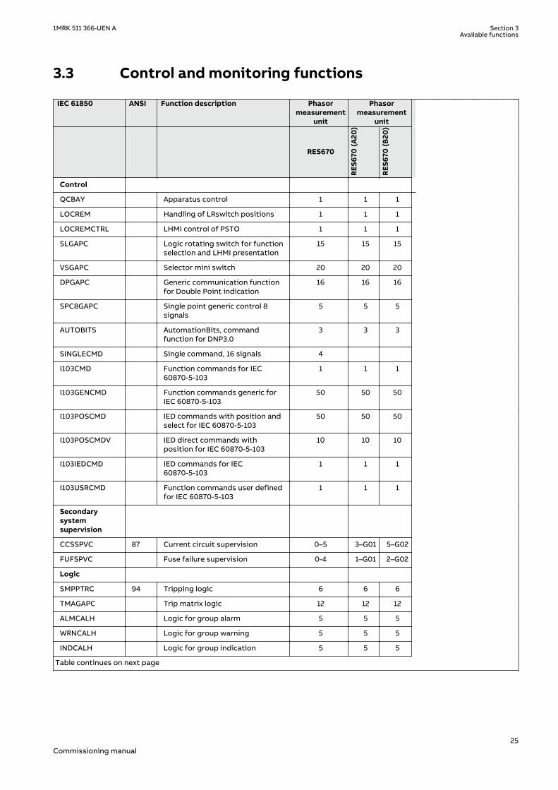
3.3 Control and monitoring functionsGUID-E3777F16-0B76-4157-A3BF-0B6B978863DE v12
IEC 61850 ANSI Function description Phasormeasurement
unit
Phasormeasurement
unit
RES670
RES6
70 (A
20)
RES6
70 (B
20)
Control
QCBAY Apparatus control 1 1 1
LOCREM Handling of LRswitch positions 1 1 1
LOCREMCTRL LHMI control of PSTO 1 1 1
SLGAPC Logic rotating switch for functionselection and LHMI presentation
15 15 15
VSGAPC Selector mini switch 20 20 20
DPGAPC Generic communication functionfor Double Point indication
16 16 16
SPC8GAPC Single point generic control 8signals
5 5 5
AUTOBITS AutomationBits, commandfunction for DNP3.0
3 3 3
SINGLECMD Single command, 16 signals 4
I103CMD Function commands for IEC60870-5-103
1 1 1
I103GENCMD Function commands generic forIEC 60870-5-103
50 50 50
I103POSCMD IED commands with position andselect for IEC 60870-5-103
50 50 50
I103POSCMDV IED direct commands withposition for IEC 60870-5-103
10 10 10
I103IEDCMD IED commands for IEC60870-5-103
1 1 1
I103USRCMD Function commands user definedfor IEC 60870-5-103
1 1 1
Secondarysystemsupervision
CCSSPVC 87 Current circuit supervision 0–5 3–G01 5–G02
FUFSPVC Fuse failure supervision 0-4 1–G01 2–G02
Logic
SMPPTRC 94 Tripping logic 6 6 6
TMAGAPC Trip matrix logic 12 12 12
ALMCALH Logic for group alarm 5 5 5
WRNCALH Logic for group warning 5 5 5
INDCALH Logic for group indication 5 5 5
Table continues on next page
1MRK 511 366-UEN A Section 3Available functions
25Commissioning manual

IEC 61850 ANSI Function description Phasormeasurement
unit
Phasormeasurement
unit
RES670
RES6
70 (A
20)
RES6
70 (B
20)
AND, GATE, INV,LLD, OR,PULSETIMER,RSMEMORY,SRMEMORY,TIMERSET, XOR
Basic configurable logic blocks(see Table 2)
40-280 40–280
40–280
ANDQT,INDCOMBSPQT,INDEXTSPQT,INVALIDQT,INVERTERQT,ORQT,PULSETIMERQT,RSMEMORYQT,SRMEMORYQT,TIMERSETQT,XORQT
Configurable logic blocks Q/T (seeTable 3)
0–1
AND, GATE, INV,LLD, OR,PULSETIMER,SLGAPC,SRMEMORY,TIMERSET,VSGAPC, XOR
Extension logic package (seeTable 4)
0–1
FXDSIGN Fixed signal function block 1 1 1
B16I Boolean 16 to Integer conversion 18 18 18
BTIGAPC Boolean 16 to Integer conversionwith Logic Node representation
16 16 16
IB16 Integer to Boolean 16 conversion 18 18 18
ITBGAPC Integer to Boolean 16 conversionwith Logic Node representation
16 16 16
TEIGAPC Elapsed time integrator with limittransgression and overflowsupervision
12 12 12
INTCOMP Comparator for integer inputs 12 12 12
REALCOMP Comparator for real inputs 12 12 12
Monitoring
CVMMXN,VMMXU, CMSQI,VMSQI, VNMMXU
Measurements 6 6 6
CMMXU Measurements 10 10 10
AISVBAS Function block for service valuepresentation of secondary analoginputs
1 1 1
EVENT Event function 20 20 20
DRPRDRE,A1RADR-A4RADR,B1RBDR-B8RBDR
Disturbance report 1 1 1
SPGAPC Generic communication functionfor Single Point indication
64 64 64
Table continues on next page
Section 3 1MRK 511 366-UEN AAvailable functions
26Commissioning manual

IEC 61850 ANSI Function description Phasormeasurement
unit
Phasormeasurement
unit
RES670
RES6
70 (A
20)
RES6
70 (B
20)
SP16GAPC Generic communication functionfor Single Point indication 16inputs
16 16 16
MVGAPC Generic communication functionfor Measured Value
24 24 24
BINSTATREP Logical signal status report 3 3 3
RANGE_XP Measured value expander block 66 66 66
SSIMG 63 Gas medium supervision 21 21 21
SSIML 71 Liquid medium supervision 3 3 3
SSCBR Circuit breaker monitoring 0-18 9-M17 18-M16
I103MEAS Measurands for IEC 60870-5-103 1 1 1
I103MEASUSR Measurands user defined signalsfor IEC 60870-5-103
3 3 3
I103AR Function status auto-recloser forIEC 60870-5-103
1 1 1
I103EF Function status earth-fault for IEC60870-5-103
1 1 1
I103FLTPROT Function status fault protectionfor IEC 60870-5-103
1 1 1
I103IED IED status for IEC 60870-5-103 1 1 1
I103SUPERV Supervison status for IEC60870-5-103
1 1 1
I103USRDEF Status for user defined signals forIEC 60870-5-103
20 20 20
L4UFCNT Event counter with limitsupervision
30 30
TEILGAPC Running hour-meter 9 9 9
Metering
PCFCNT Pulse-counter logic 16 16 16
ETPMMTR Function for energy calculationand demand handling
6 6 6
Table 2: Total number of instances for basic configurable logic blocks
Basic configurable logic block Total number of instances
AND 280
GATE 40
INV 420
LLD 40
OR 280
PULSETIMER 40
RSMEMORY 40
Table continues on next page
1MRK 511 366-UEN A Section 3Available functions
27Commissioning manual

Basic configurable logic block Total number of instances
SRMEMORY 40
TIMERSET 60
XOR 40
Table 3: Total number of instances for configurable logic blocks Q/T
Configurable logic blocks Q/T Total number of instances
ANDQT 120
INDCOMBSPQT 20
INDEXTSPQT 20
INVALIDQT 22
INVERTERQT 120
ORQT 120
PULSETIMERQT 40
RSMEMORYQT 40
SRMEMORYQT 40
TIMERSETQT 40
XORQT 40
Table 4: Total number of instances for extended logic package
Extended configurable logic block Total number of instances
AND 180
GATE 49
INV 180
LLD 49
OR 180
PULSETIMER 59
SLGAPC 74
SRMEMORY 110
TIMERSET 49
VSGAPC 130
XOR 49
Section 3 1MRK 511 366-UEN AAvailable functions
28Commissioning manual
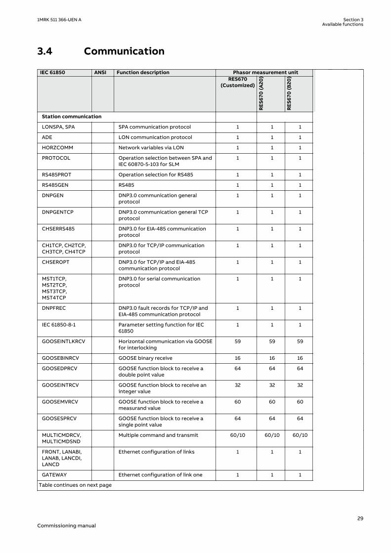
3.4 CommunicationGUID-5F144B53-B9A7-4173-80CF-CD4C84579CB5 v12
IEC 61850 ANSI Function description Phasor measurement unit RES670
(Customized)
RES6
70 (A
20)
RES6
70 (B
20)
Station communication
LONSPA, SPA SPA communication protocol 1 1 1
ADE LON communication protocol 1 1 1
HORZCOMM Network variables via LON 1 1 1
PROTOCOL Operation selection between SPA andIEC 60870-5-103 for SLM
1 1 1
RS485PROT Operation selection for RS485 1 1 1
RS485GEN RS485 1 1 1
DNPGEN DNP3.0 communication generalprotocol
1 1 1
DNPGENTCP DNP3.0 communication general TCPprotocol
1 1 1
CHSERRS485 DNP3.0 for EIA-485 communicationprotocol
1 1 1
CH1TCP, CH2TCP,CH3TCP, CH4TCP
DNP3.0 for TCP/IP communicationprotocol
1 1 1
CHSEROPT DNP3.0 for TCP/IP and EIA-485communication protocol
1 1 1
MST1TCP,MST2TCP,MST3TCP,MST4TCP
DNP3.0 for serial communicationprotocol
1 1 1
DNPFREC DNP3.0 fault records for TCP/IP andEIA-485 communication protocol
1 1 1
IEC 61850-8-1 Parameter setting function for IEC61850
1 1 1
GOOSEINTLKRCV Horizontal communication via GOOSEfor interlocking
59 59 59
GOOSEBINRCV GOOSE binary receive 16 16 16
GOOSEDPRCV GOOSE function block to receive adouble point value
64 64 64
GOOSEINTRCV GOOSE function block to receive aninteger value
32 32 32
GOOSEMVRCV GOOSE function block to receive ameasurand value
60 60 60
GOOSESPRCV GOOSE function block to receive asingle point value
64 64 64
MULTICMDRCV,MULTICMDSND
Multiple command and transmit 60/10 60/10 60/10
FRONT, LANABI,LANAB, LANCDI,LANCD
Ethernet configuration of links 1 1 1
GATEWAY Ethernet configuration of link one 1 1 1
Table continues on next page
1MRK 511 366-UEN A Section 3Available functions
29Commissioning manual

IEC 61850 ANSI Function description Phasor measurement unit RES670
(Customized)
RES6
70 (A
20)
RES6
70 (B
20)
OPTICAL103 IEC 60870-5-103 Optical serialcommunication
1 1 1
RS485103 IEC 60870-5-103 serial communicationfor RS485
1 1 1
AGSAL Generic security applicationcomponent
1 1 1
LD0LLN0 IEC 61850 LD0 LLN0 1 1 1
SYSLLN0 IEC 61850 SYS LLN0 1 1 1
LPHD Physical device information 1 1 1
PCMACCS IED Configuration Protocol 1 1 1
SECALARM Component for mapping securityevents on protocols such as DNP3 andIEC103
1 1 1
FSTACCSFSTACCSNA
Field service tool access via SPAprotocol over ethernetcommunication
1 1 1
ACTIVLOG Activity logging parameters 1 1 1
ALTRK Service Tracking 1 1 1
SINGLELCCH Single ethernet port link status 1 1 1
PRPSTATUS Dual ethernet port link status 1 1 1
Process bus communication IEC61850-9-2 1)
PRP IEC 62439-3 parallel redundancyprotocol
0-1 1-P03 1-P03
Remote communication
Binary signal transfer receive/transmit
6/36 6/36 6/36
Transmission of analog data fromLDCM
1 1 1
Receive binary status from remoteLDCM
6/3/3 6/3/3 6/3/3
1) Only included for 9-2LE products
Section 3 1MRK 511 366-UEN AAvailable functions
30Commissioning manual

3.5 Basic IED functionsGUID-C8F0E5D2-E305-4184-9627-F6B5864216CA v9
Table 5: Basic IED functions
IEC 61850 or functionname
Description
INTERRSIGSELFSUPEVLST Self supervision with internal event list
TIMESYNCHGEN Time synchronization module
SYNCHCAN,SYNCHCMPPS,SYNCHPPS, SNTP,SYNCHCMPPS
Time synchronization
TIMEZONE Time synchronization
DSTBEGIN,DSTENABLE, DSTEND
GPS time synchronization module
IRIG-B Time synchronization
SETGRPS Number of setting groups
ACTVGRP Parameter setting groups
TESTMODE Test mode functionality
CHNGLCK Change lock function
SMBI Signal matrix for binary inputs
SMBO Signal matrix for binary outputs
SMMI Signal matrix for mA inputs
SMAI1 - SMAI12 Signal matrix for analog inputs
3PHSUM Summation block 3 phase
ATHSTAT Authority status
ATHCHCK Authority check
AUTHMAN Authority management
FTPACCS FTP access with password
SPACOMMMAP SPA communication mapping
SPATD Date and time via SPA protocol
DOSFRNT Denial of service, frame rate control for front port
DOSLANAB Denial of service, frame rate control for OEM port AB
DOSLANCD Denial of service, frame rate control for OEM port CD
DOSSCKT Denial of service, socket flow control
GBASVAL Global base values for settings
PRIMVAL Primary system values
ALTMS Time master supervision
ALTIM Time management
MSTSER DNP3.0 for serial communication protocol
PRODINF Product information
RUNTIME IED Runtime Comp
CAMCONFIG Central account management configuration
Table continues on next page
1MRK 511 366-UEN A Section 3Available functions
31Commissioning manual

IEC 61850 or functionname
Description
CAMSTATUS Central account management status
TOOLINF Tools Information component
SAFEFILECOPY Safe file copy function
Table 6: Local HMI functions
IEC 61850 or functionname
ANSI Description
LHMICTRL Local HMI signals
LANGUAGE Local human machine language
SCREEN Local HMI Local human machine screen behavior
FNKEYTY1–FNKEYTY5FNKEYMD1–FNKEYMD5
Parameter setting function for HMI in PCM600
LEDGEN General LED indication part for LHMI
OPENCLOSE_LED LHMI LEDs for open and close keys
GRP1_LED1–GRP1_LED15GRP2_LED1–GRP2_LED15GRP3_LED1–GRP3_LED15
Basic part for CP HW LED indication module
Section 3 1MRK 511 366-UEN AAvailable functions
32Commissioning manual

Section 4 Starting up
4.1 Factory and site acceptance testingGUID-38C2B5FA-9210-4D85-BA21-39CE98A1A84A v2
Testing the proper IED operation is carried out at different occasions, for example:
• Acceptance testing• Commissioning testing• Maintenance testing
This manual describes the workflow and the steps to carry out the commissioning testing.
Factory acceptance testing (FAT) is typically done to verify that the IED and its correspondingconfiguration meet the requirements of the utility or industry. This test is the most complexand in depth, as it is done to familiarize the user with a new product or to verify a newconfiguration. The complexity of this testing depends on several factors, such as:
• New IED type• New configuration• Modified configuration
Site acceptance testing (SAT or commissioning testing) is typically done to verify that theinstalled IED is correctly set and connected to the power system. SAT requires that theacceptance testing has been performed and that the application configuration is verified.
Maintenance testing is a periodic verification that the IED is healthy and has correct settings,depending on changes in the power system. There are also other types of maintenancetesting.
4.2 Commissioning checklistGUID-93D14E4E-5DDE-4D37-84A6-2DF0656AB73D v3
Before starting up commissioning at site, check that the following items are available.
• Single line diagram• Protection block diagram• Circuit diagram• Setting list and configuration• RJ-45 Ethernet cable (CAT 5)• Three-phase test kit or other test equipment depending on the complexity of the
configuration and functions to be tested.• PC with PCM600 installed along with the connectivity packages corresponding to the IEDs
to be tested.• Administration rights on the PC, to set up IP addresses• Product documentation (engineering manual, installation manual, commissioning manual,
operation manual, technical manual and communication protocol manual)
1MRK 511 366-UEN A Section 4Starting up
33Commissioning manual

4.3 Checking the power supplyM11725-2 v6
Do not insert anything else to the female connector but the correspondingmale connector. Inserting anything else (such as a measurement probe) maydamage the female connector and prevent a proper electrical contact betweenthe printed circuit board and the external wiring connected to the screwterminal block.
Check that the auxiliary supply voltage remains within the permissible input voltage rangeunder all operating conditions. Check that the polarity is correct before energizing the IED.
4.4 Energizing the IED
4.4.1 Checking the IED operationM11726-2 v7
Check all connections to external circuitry to ensure correct installation, before energizing theIED and carrying out the commissioning procedures.
Energize the power supply of the IED to start it up. Keep the DC power supply on until the Rootmenu or the selected default screen is shown on the HMI before interrupting the DC powersupply again. The energization could be done in a number of ways, from energizing a wholecubicle with many IEDs to energizing each single IED one by one.
If HW (i.e. I/O and/or communication boards etc.) have been changed (i.e. removed, replaced,or added), the user should re-configure the IED by navigating in the local HMI menu to: Mainmenu/Configuration/Reconfigure HW modules to activate the changed hardware modules inorder to enable the self-supervision function to detect possible hardware errors.
Check also the self-supervision function in Main menu/Diagnostics/IED status/General menuin local HMI to verify that the IED operates properly.
Set the IED time if no time synchronization source is configured.
To ensure that the IED is according to the delivery and ordering specifications documentsdelivered together with each IED, the user should also after start-up use the built in HMI tocheck the IED's:
• Software version, Main menu/Diagnostics/IED status/Product identifiers.• Serial number, Main menu/Diagnostics/IED status/Product identifiers.• Installed modules and their ordering number, Main menu/Diagnostics/IED status/
Installed HW.
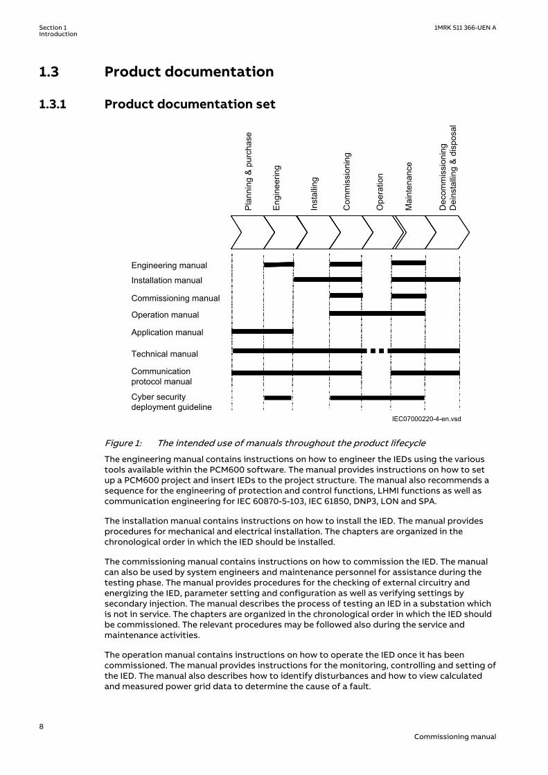
4.4.2 IED start-up sequenceM11727-3 v11
When the IED is energized, the green LED starts flashing instantly. After approximately 55seconds the window lights up and the window displays ‘IED Startup’. The main menu isdisplayed and the upper row should indicate ‘Ready’ after about 90 seconds. A steady greenlight indicates a successful startup.
Section 4 1MRK 511 366-UEN AStarting up
34Commissioning manual

xx04000310-1-en.vsd
t (s)0 t1 t2
1 32
IEC04000310 V2 EN-US
Figure 2: Typical IED start-up sequence
1 IED energized. Green LED instantly starts flashing
2 LCD lights up and "IED startup" is displayed
3 The main menu is displayed. A steady green light indicates a successful startup.
If the upper row in the window indicates ‘Fail’ instead of ‘Ready’ and the green LED flashes, aninternal failure in the IED has been detected. See section"Checking the self supervisionfunction" to investigate the fault.
4.5 Setting up communication between PCM600 and theIED
SEMOD58570-5 v12
The communication between the IED and PCM600 is independent of the communicationprotocol used within the substation or to the NCC.
The communication media is always Ethernet and the used protocol is TCP/IP.
Each IED has an RJ-45 Ethernet interface connector on the front. The front Ethernet connectorshall be used for communication with PCM600.
When an Ethernet-based station protocol is used, PCM600 communication can use the sameEthernet port and IP address.
To connect PCM600 to the IED, two basic variants must be considered.
• Direct point-to-point link between PCM600 and the IED front port. The front port can beseen as a service port.
• Indirect link via a station LAN or from remote via a network.
The physical connection and the IP address must be configured in both cases to enablecommunication.
The communication procedures are the same in both cases.
1. If needed, set the IP address for the IEDs.2. Set up the PC or workstation for a direct link (point-to-point), or3. Connect the PC or workstation to the LAN/WAN network.4. Configure the IED IP addresses in the PCM600 project for each IED to match the IP
addresses of the physical IEDs.
Setting up IP addresses
The IP address and the corresponding communication subnetwork mask must be set via theLHMI for each available Ethernet interface in the IED. Each Ethernet interface has a defaultfactory IP address when the IED is delivered. The IP adress and the subnetwork mask mighthave to be reset when an additional Ethernet interface is installed or an interface is replaced.
1MRK 511 366-UEN A Section 4Starting up
35Commissioning manual

• The default IP address for the IED front port is 10.1.150.3 and the correspondingsubnetwork mask is 255.255.255.0, which can be set via the local HMI path Main menu/Configuration/Communication/Ethernet configuration/FRONT:1.
Setting up the PC or workstation for point-to-point access to IEDs frontport
An ethernet cable (max 2 m length) with RJ-45 connectors is needed to connect two physicalEthernet interfaces together without a hub, router, bridge or switch in between.
IEC09000096-2-en.vsd
Tx Tx
Rx Rx
RJ-45IED PCM600
IEC09000096 V2 EN-US
Figure 3: Point-to-point link between IED and PCM600
The following description is an example valid for standard PCs using Microsoft Windowsoperating system. The example is taken from a Laptop with one Ethernet interface.
Administrator rights are required to change the PC communication setup. It isautomatically detected that Tx signals from the IED are received on the Tx pinon the PC. Thus, a straight (standard) Ethernet cable can be used.
1. Select Search programs and files in the Start menu in Windows.
Section 4 1MRK 511 366-UEN AStarting up
36Commissioning manual
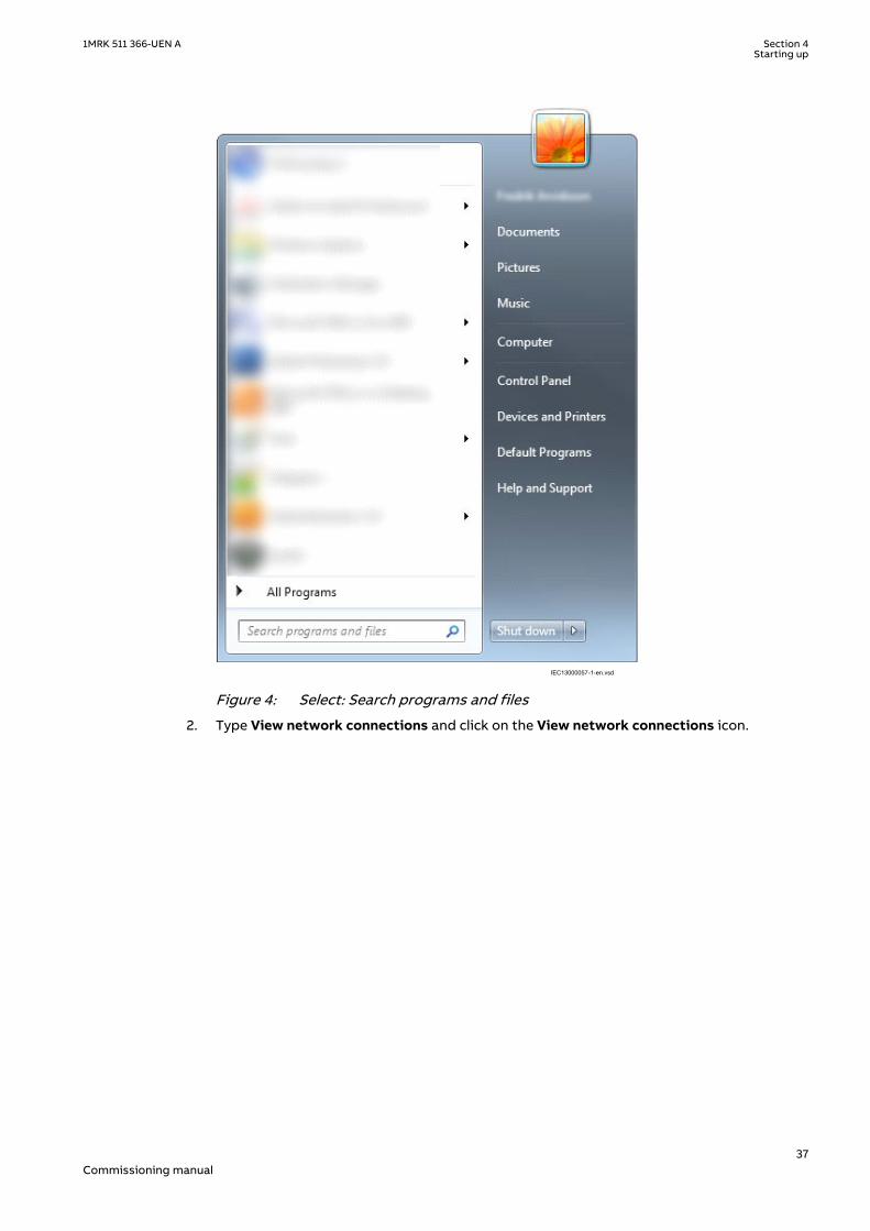
IEC13000057-1-en.vsdIEC13000057 V1 EN-US
Figure 4: Select: Search programs and files
2. Type View network connections and click on the View network connections icon.
1MRK 511 366-UEN A Section 4Starting up
37Commissioning manual

IEC13000058-1-en.vsdIEC13000058 V1 EN-US
Figure 5: Click View network connections
3. Right-click and select Properties.
IEC13000059-1-en.vsd
IEC13000059 V1 EN-US
Figure 6: Right-click Local Area Connection and select Properties
4. Select the TCP/IPv4 protocol from the list of configured components using thisconnection and click Properties.
Section 4 1MRK 511 366-UEN AStarting up
38Commissioning manual

IEC13000060-1-en.vsdIEC13000060 V1 EN-US
Figure 7: Select the TCP/IPv4 protocol and open Properties
5. Select Use the following IP address and define IP address and Subnet mask if the frontport is used and if the IP address is not set to be obtained automatically by the IED, seeFigure 8. The IP address must be different from the IP address chosen for the IED.
IEC13000062-1-en.vsdIEC13000062 V1 EN-US
Figure 8: Select: Use the following IP address
6. Use the ping command to verify connectivity with the IED.7. Close all open windows and start PCM600.
1MRK 511 366-UEN A Section 4Starting up
39Commissioning manual

The PC and IED must belong to the same subnetwork for this set-up to work.
Setting up the PC to access the IED via a network
The same method is used as for connecting to the front port.
The PC and IED must belong to the same subnetwork for this set-up to work.
4.6 Writing an application configuration to the IEDM11734-2 v6
When writing a configuration to the IED with PCM600, the IED is automatically set inconfiguration mode. When the IED is set in configuration mode, all functions are blocked. Thered LED on the IED flashes, and the green LED is lit while the IED is in the configuration mode.
When the configuration is written and completed, the IED is automatically set into normalmode. For further instructions please refer to the users manuals for PCM600.
4.7 Checking CT circuitsM12182-2 v15
Check that the wiring is in strict accordance with the supplied connectiondiagram.
The CTs must be connected in accordance with the circuit diagram provided with the IED, bothwith regards to phases and polarity. The following tests shall be performed on every primaryCT connected to the IED:
• Primary injection test to verify the current ratio of the CT, the correct wiring up to theprotection IED and correct phase sequence connection (that is L1, L2, L3.)
• Polarity check to prove that the predicted direction of secondary current flow is correctfor a given direction of primary current flow. This is an essential test for the properoperation of the differential function and directional protection functions.
• CT secondary loop resistance measurement to confirm that the current transformersecondary loop DC resistance is within the specification for the connected protectionfunctions. When the measured loop resistance is near the calculated value for maximumDC resistance, perform a complete burden test.
• CT excitation test in order to confirm that the current transformer is of the correctaccuracy rating and that there are no shorted turns in the current transformer windings.Manufacturer's design curves must be available for the current transformer to comparethe actual results.
• Earthing check of the individual CT secondary circuits to verify that each three-phase setof main CTs is properly connected to the station earth and only at one electrical point.
• Insulation resistance check.
While the CT primary is energized, the secondary circuit shall never be opencircuited because extremely dangerous high voltages may arise.
Section 4 1MRK 511 366-UEN AStarting up
40Commissioning manual

Both the primary and the secondary sides must be disconnected from the lineand the IED when plotting the excitation characteristics.
If the CT secondary circuit earth connection is removed without the currenttransformer primary being de-energized, dangerous voltages may result in thesecondary CT circuits.
4.8 Checking VT circuitsM11724-2 v10
Check that the wiring is in strict accordance with the supplied connection diagram.
Correct possible errors before continuing to test the circuitry.
Test the circuitry.
• Polarity check when applicable; this test is often omitted for CVTs• VT circuit voltage measurement (primary injection test)• Earthing check• Phase relationship• Insulation resistance check
The primary injection test verifies the VT ratio and the wiring all the way from the primarysystem to the IED. Injection must be performed for each phase-to-neutral circuit.
While testing VT secondary circuit and associated secondary equipment, careshall be exercised to isolate the VT from the circuit being tested to avoidbackcharging the VT from the secondary side.
4.9 Using the RTXP test switchGUID-F1E29C06-7FE8-44D8-AD5A-EE8990A2AA41 v5
The RTXP test switch is designed to provide the means of safe testing of the IED. This isachieved by the electromechanical design of the test switch and test plug handle. When thetest plug handle is inserted, it first blocks the trip and alarm circuits then it short circuits theCT secondary circuit and opens the VT secondary circuits making the IED available forsecondary injection.
When pulled out, the test handle is mechanically stopped in half withdrawn position. In thisposition, the current and voltage enter the protection, but the alarm and trip circuits are stillisolated and the IED is in test mode. Before removing the test handle, check the measuredvalues in the IED.
Not until the test handle is completely removed, the trip and alarm circuits are restored foroperation.
1MRK 511 366-UEN A Section 4Starting up
41Commissioning manual

Verify that the contact sockets have been crimped correctly and that they arefully inserted by tugging on the wires. Never do this with current circuits inservice.
Current circuit
1. Verify that the contacts are of current circuit type.2. Verify that the short circuit jumpers are located in the correct slots.
Voltage circuit
1. Verify that the contacts are of voltage circuit type.2. Check that no short circuit jumpers are located in the slots dedicated for voltage.
Trip and alarm circuits
1. Check that the correct types of contacts are used.
4.10 Checking the binary I/O circuitsM11722-2 v3
Do not insert anything else to the female connector but the correspondingmale connector. Inserting anything else (such as a measurement probe) maydamage the female connector and prevent a proper electrical contact betweenthe printed circuit board and the external wiring connected to the screwterminal block.
4.10.1 Binary input circuitsM11722-4 v3
Preferably, disconnect the binary input connector from the binary input cards. Check allconnected signals so that both input level and polarity are in accordance with the IEDspecifications.
4.10.2 Binary output circuitsM11722-8 v3
Preferably, disconnect the binary output connector from the binary output cards. Check allconnected signals so that both load and polarity are in accordance with IED specifications.
4.11 Checking optical connectionsM16022-2 v7
Check that the Tx and Rx optical connections are correct.
An IED equipped with optical connections has an minimum space requirementof 180 mm for plastic fiber cables and 275 mm for glass fiber cables. Check theallowed minimum bending radius from the optical cable manufacturer.
Section 4 1MRK 511 366-UEN AStarting up
42Commissioning manual
Section 5 Configuring the IED and changingsettings
5.1 OverviewM11730-2 v6
The customer specific values for each setting parameter and a configuration file have to beavailable before the IED can be set and configured, if the IED is not delivered with aconfiguration.
Use the configuration tools in PCM600 to verify that the IED has the expected configuration.
Each function included in the IED has several setting parameters, which have to be set in orderto make the IED behave as intended. A factory default value is provided for eachparameter.The Parameter Setting Tool in PCM600 is used when changing setting parameters.
All settings can be
• Entered manually through the local HMI.• Written from a PC, either locally or remotely using PCM600. Front or rear port
communication has to be established before the settings can be written to the IED.
Make sure that the DC supply is not turned off when the IED saves the writtenconfiguration.
The IED uses a FLASH disk for storing configuration data and process data like counters,object states, Local/Remote switch position etc. Since FLASH memory is used, measures havebeen taken in software to make sure that the FLASH disk is not worn out by too intensivestoring of data.
This means, that to be absolutely sure that all data have been saved to FLASH, it is necessaryto leave the IED with auxiliary power connected after all the commissioning is done (includingsetting the Local/Remote switch to the desired position) for at least one hour after the lastcommissioning action performed on the IED.
After that time has elapsed, it will be safe to turn the IED off, no data will be lost.
5.2 Configuring analog CT inputsM12312-6 v8
The analog input channels must be configured to get correct measurement results as well ascorrect protection functionality. Because all protection algorithms in the IED utilize theprimary system quantities, it is extremely important to make sure that connected currenttransformer settings are done properly. These data are calculated by the system engineer andnormally set by the commissioner from the local HMI or from PCM600.
The analog inputs on the transformer input module are dimensioned for either 1A or 5A. Eachtransformer input module has a unique combination of current and voltage inputs. Make surethe input current rating is correct and that it matches the order documentation.
The primary CT data are entered via the HMI menu under Main menu/Configurations/Analogmodules
1MRK 511 366-UEN A Section 5Configuring the IED and changing settings
43Commissioning manual

The following parameter shall be set for every current transformer connected to the IED:
Table 7: CT configuration
Parameter description Parameter name Range Default
Rated CT primary current in A CTPRIMnn = channel number
from 0 to 99999 3000
This parameter defines the primary rated current of the CT. For two set of CTs with ratio1000/1 and 1000/5 this parameter is set to the same value of 1000 for both CT inputs. Theparameter CTStarPoint can be used in order to reverse the direction of the CT. This might benecessary if two sets of CTs have different star point locations in relation to the protectedbusbar.
For main CTs with 2A rated secondary current, it is recommended to connect the secondarywiring to the 1A input.
Take the rated permissive overload values for the current inputs intoconsideration.
5.3 Reconfiguring the IEDM11728-2 v2
I/O modules configured with PCM600 (BIM, BOM or IOM) are supervised.
I/O modules that are not configured are not supervised.
Each logical I/O module has an error flag that indicates signal or module failure. The error flagis also set when the physical I/O module of the correct type is not detected in the connectedslot.
Section 5 1MRK 511 366-UEN AConfiguring the IED and changing settings
44Commissioning manual
Section 6 Establishing connection andverifying the SPA/IECcommunication
6.1 Entering settingsM11735-2 v1
If the IED is connected to a monitoring or control system via the rear SPA/IEC port, theSPA/IEC port has to be set either for SPA or IEC use.
6.1.1 Entering SPA settingsM11735-7 v4
The SPA/IEC port is located on the rear side of the IED. Two types of interfaces can be used:
• for plastic fibers with connector type HFBR• for glass fibers with connectors type ST
When using the SPA protocol, the rear SPA/IEC port must be set for SPA use.
Procedure
1. Set the operation of the rear optical SPA/IEC port to “SPA”.The operation of the rear SPA port can be found on the local HMI under Main menu/Configuration/Communication/Station communication/Port configuration/SLMoptical serial port/PROTOCOL:1When the setting is entered the IED restarts automatically. After the restart the SPA/IECport operates as a SPA port.
2. Set the slave number and baud rate for the rear SPA portThe slave number and baud rate can be found on the local HMI under Main menu/Configuration/Communication/Station communication/SPA/SPA:1Set the same slave number and baud rate as set in the SMS system for the IED.
6.1.2 Entering IEC settingsM11735-32 v4
When using the IEC protocol, the rear SPA/IEC port must be set for IEC use.
Two types of interfaces can be used:
• for plastic fibers with connector type HFBR• for glass fibers with connectors type ST
Procedure
1. Set the operation of the rear SPA/IEC port to “IEC”.The operation of the rear SPA/IEC port can be found on the local HMI under Main menu/Configuration/Communication/SLM configuration/Rear optical SPA-IEC-DNP port/PROTOCOL:1
1MRK 511 366-UEN A Section 6Establishing connection and verifying the SPA/IEC communication
45Commissioning manual

When the setting is entered the IED restarts automatically. After the restart the selectedIEC port operates as an IEC port.
2. Set the slave number and baud rate for the rear IEC port.The slave number and baud rate can be found on the local HMI under Main menu/Configuration/Communication/SLM configuration/Rear optical SPA-IEC-DNP port/IEC60870–5–103Set the same slave number and baud rate as set in the IEC master system for the IED.
6.2 Verifying the communicationM11735-77 v1
To verify that the rear communication with the SMS/SCS system is working, there are somedifferent methods. Choose one of the following.
6.2.1 Verifying SPA communicationM11735-81 v4
Procedure
1. Use a SPA-emulator and send “RF” to the IED. The answer from the IED should be the typeand version of it, for example, “REL670 2.1...”.
2. Generate one binary event by activating a function, which is configured to an event blockwhere the used input is set to generate events on SPA. The configuration must be madewith the PCM600 software. Verify that the event is presented in the SMS/SCS system.
During the following tests of the different functions in the IED, verify that the events andindications in the SMS/SCS system are as expected.
6.2.2 Verifying IEC communicationM11735-91 v2
To verify that the IEC communication with the IEC master system is working, there are somedifferent methods. Choose one of the following.
Procedure
1. Check that the master system time-out for response from the IED, for example after asetting change, is > 40 seconds.
2. Use a protocol analyzer and record the communication between the IED and the IECmaster. Check in the protocol analyzer’s log that the IED answers the master messages.
3. Generate one binary event by activating a function that is configured to an event blockwhere the used input is set to generate events on IEC. The configuration must be madewith the PCM600 software. Verify that the event is presented in the IEC master system.
During the following tests of the different functions in the IED, verify that the events andindications in the IEC master system are as expected.
6.3 fiber optic loopM11905-3 v5
The SPA communication is mainly used for SMS. It can include different numerical IEDs withremote communication possibilities. The fiber optic loop can contain < 20-30 IEDs dependingon requirements on response time. Connection to a personal computer (PC) can be madedirectly (if the PC is located in the substation) or by telephone modem through a telephonenetwork with ITU (CCITT) characteristics.
Section 6 1MRK 511 366-UEN AEstablishing connection and verifying the SPA/IEC communication
46Commissioning manual

Table 8: Max distances between IEDs/nodes
glass < 1000 m according to optical budget
plastic < 25 m (inside cubicle) according to optical budget
6.4 Optical budget calculation for serial communicationwith SPA/IEC
M11736-4 v2
Table 9: Example
Distance 1 kmGlass
Distance 25 mPlastic
Maximum attenuation - 11 dB - 7 dB
4 dB/km multi mode: 820 nm - 62.5/125 um 4 dB -
0.16 dB/m plastic: 620 nm - 1mm - 4 dB
Margins for installation, aging, and so on 5 dB 1 dB
Losses in connection box, two contacts (0.5 dB/contact)
1 dB -
Losses in connection box, two contacts (1 dB/contact)
- 2 dB
Margin for 2 repair splices (0.5 dB/splice) 1 dB -
Maximum total attenuation 11 dB 7 dB
1MRK 511 366-UEN A Section 6Establishing connection and verifying the SPA/IEC communication
47Commissioning manual

48
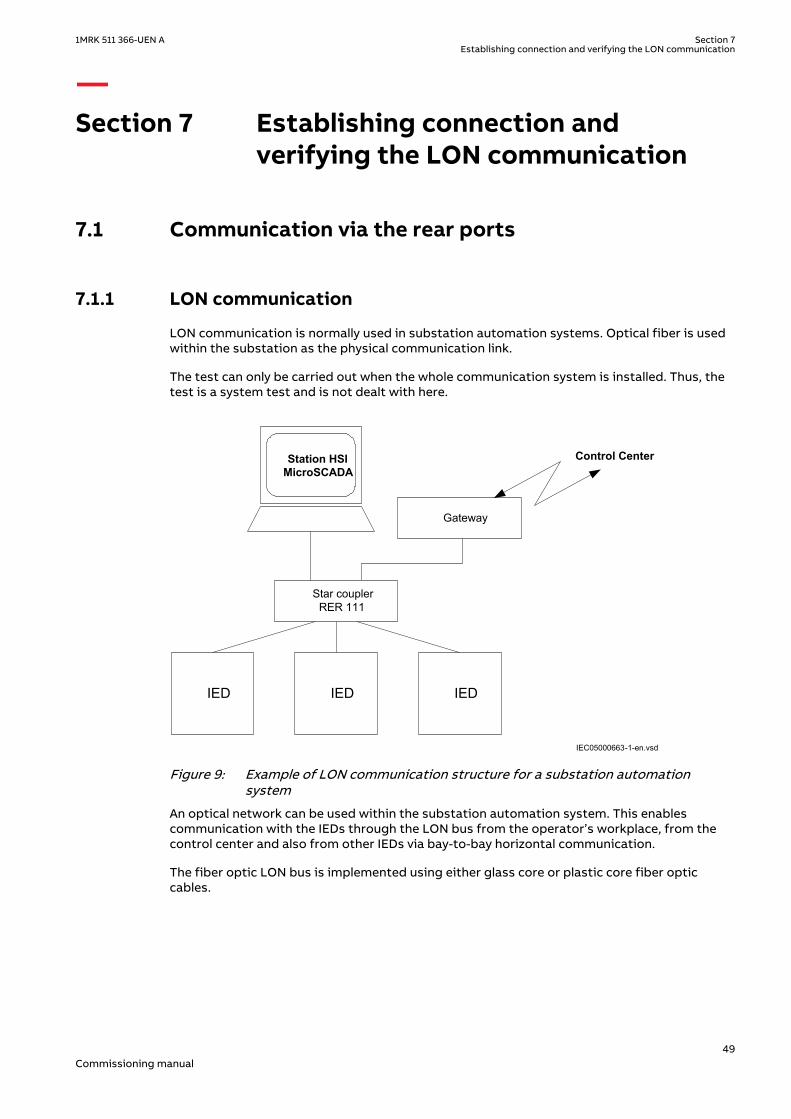
Section 7 Establishing connection andverifying the LON communication
7.1 Communication via the rear portsM12196-2 v1
7.1.1 LON communicationM12196-4 v4
LON communication is normally used in substation automation systems. Optical fiber is usedwithin the substation as the physical communication link.
The test can only be carried out when the whole communication system is installed. Thus, thetest is a system test and is not dealt with here.
M14804-3 v3
Control Center
IED IEDIED
Gateway
Star couplerRER 111
Station HSIMicroSCADA
IEC05000663-1-en.vsdIEC05000663 V2 EN-US
Figure 9: Example of LON communication structure for a substation automationsystem
An optical network can be used within the substation automation system. This enablescommunication with the IEDs through the LON bus from the operator’s workplace, from thecontrol center and also from other IEDs via bay-to-bay horizontal communication.
The fiber optic LON bus is implemented using either glass core or plastic core fiber opticcables.
1MRK 511 366-UEN A Section 7Establishing connection and verifying the LON communication
49Commissioning manual
Table 10: Specification of the fiber optic connectors
Glass fiber Plastic fiber
Cable connector ST-connector snap-in connector
Cable diameter 62.5/125 m 1 mm
Max. cable length 1000 m 10 m
Wavelength 820-900 nm 660 nm
Transmitted power -13 dBm (HFBR-1414) -13 dBm (HFBR-1521)
Receiver sensitivity -24 dBm (HFBR-2412) -20 dBm (HFBR-2521)
7.1.2 The LON ProtocolM14804-32 v2
The LON protocol is specified in the LonTalkProtocol Specification Version 3 from EchelonCorporation. This protocol is designed for communication in control networks and is a peer-to-peer protocol where all the devices connected to the network can communicate with eachother directly. For more information of the bay-to-bay communication, refer to the sectionMultiple command function.
7.1.3 Hardware and software modulesM14804-35 v4
The hardware needed for applying LON communication depends on the application, but onevery central unit needed is the LON Star Coupler and optical fibers connecting the star couplerto the IEDs. To interface the IEDs from the MicroSCADA with Classic Monitor, applicationlibrary LIB520 is required.
The HV Control 670 software module is included in the LIB520 high-voltage process package,which is a part of the Application Software Library in MicroSCADA applications.
The HV Control 670 software module is used for control functions in the IEDs. The modulecontains a process picture, dialogues and a tool to generate a process database for thecontrol application in MicroSCADA.
When using MicroSCADA Monitor Pro instead of the Classic Monitor, SA LIB is used togetherwith 670 series Object Type files.
The HV Control 670 software module and 670 series Object Type files are usedwith both 650 and 670 series IEDs.
Use the LON Network Tool (LNT) to set the LON communication. This is a software toolapplied as one node on the LON bus. To communicate via LON, the IEDs need to know
• The node addresses of the other connected IEDs.• The network variable selectors to be used.
This is organized by LNT.
The node address is transferred to LNT via the local HMI by setting the parameterServicePinMsg = Yes. The node address is sent to LNT via the LON bus, or LNT can scan thenetwork for new nodes.
The communication speed of the LON bus is set to the default of 1.25 Mbit/s. This can bechanged by LNT.
Section 7 1MRK 511 366-UEN AEstablishing connection and verifying the LON communication
50Commissioning manual

7.2 Optical budget calculation for serial communicationwith LON
M11737-4 v2
Table 11: Example
Distance 1 kmGlass
Distance10 mPlastic
Maximum attenuation -11 dB - 7 dB
4 dB/km multi mode: 820 nm - 62.5/125 um 4 dB -
0.3 dB/m plastic: 620 nm - 1mm - 3 dB
Margins for installation, aging, and so on 5 dB 2 dB
Losses in connection box, two contacts (0.75 dB/contact) 1.5 dB -
Losses in connection box, two contacts (1dB/contact) - 2 dB
Margin for repair splices (0.5 dB/splice) 0.5 dB -
Maximum total attenuation 11 dB 7 dB
1MRK 511 366-UEN A Section 7Establishing connection and verifying the LON communication
51Commissioning manual

52

Section 8 Establishing connection andverifying the IEC 61850communication
8.1 OverviewSEMOD172103-4 v6
The rear OEM ports are used for:
• process bus (IEC 61850-9-2LE) communication• IEEE C37.118/1344 communication• substation bus (IEC 61850-8-1) communication.
For IEC 61850-8-1 redundant communication, both rear OEM ports are utilized. In this case IEC61850-9-2LE communication can not be used.
IEC 61850-9-2LE process bus communication is not supported in the IED.
8.2 Setting the station communicationSEMOD172108-3 v10
To enable IEC 61850 communication the corresponding OEM ports must be activated. The rearOEM port AB and CD is used for IEC 61850-8-1 communication. The rear OEM port CD is usedfor IEC 61850-9-2LE communication. For IEC 61850-8-1 redundant communication, both OEMport AB and CD are used exclusively.
IEC 61850-9-2LE communication can only be used on OEM rear port X311:C, D.
To enable IEC 61850 station communication:
1. Enable IEC 61850-8-1 (substation bus) communication for port AB.
1.1. Set values for the rear ports AB.Navigate to: Main menu/Configuration/Communication/Ethernet configuration/LANAB:1Set values for Mode, IPAddress and IPMask. Mode must be set to Normal.Check that the correct IP address is assigned to the port.
1.2. Enable IEC 61850-8-1 communication.Navigate to: Main menu/Configuration/Communication/Station communication/IEC61850-8-1/IEC61850–8–1:1Set Operation to On , PortSelGOOSE and PortSelMMS to the port used (for exampleLANAB).
2. Enable redundant IEC 61850-8-1 communication for port AB and CD
2.1. Enable redundant communication.
1MRK 511 366-UEN A Section 8Establishing connection and verifying the IEC 61850 communication
53Commissioning manual
Navigate to: Main menu/Configuration/Communication/Ethernet configuration/PRP:1Set values for Operation, IPAddress and IPMask. Operation must be set to On.The IED will restart after confirmation. Menu items LANAB:1 and LANCD:1 arehidden in local HMI after restart but are visible in PST where the values forparameter Mode is set to Duo.
3. Enable IEC 61850-9-2LE (process bus) communication for port CD.
3.1. Set values for the rear port CD.Navigate to: Main menu/Configuration/Communication/Ethernet configuration/LANCD:1Set values for Mode, IPAddress and IPMask. Mode must be set to IEC9-2.
There are no settings needed for the IEC 61850-9-2LE communication in the local HMI branchStation communication. Make sure that the optical fibers are connected correctly.Communication is enabled whenever the merging unit starts sending data.
8.3 Verifying the communicationSEMOD172108-24 v8
To verify that the communication is working a test/analyzing tool, for example ITT600, can be used.
Verifying redundant IEC 61850-8-1 communication
Ensure that the IED receives IEC 61850-8-1 data on both port AB and CD. Browse in the localHMI to Main menu/Diagnostics/Communication/Redundant PRP and check that both signalsLAN-A-STATUS and LAN-B-STATUS are shown as Ok. Remove the optical connection to one ofthe ports AB or CD. Verify that either signal LAN-A-STATUS or LAN-B-STATUS (depending onwhich connection that was removed) are shown as Error and the that other signal is shown asOk. Be sure to re-connect the removed connection after completed verification.
Section 8 1MRK 511 366-UEN AEstablishing connection and verifying the IEC 61850 communication
54Commissioning manual

Section 9 Establishing connection andverifying the IEEE C37.118/1344communication
9.1 OverviewGUID-EFD77C28-6F7C-4277-8C7E-30E78CC8EFAD v2
The IED can support synchrophasor data communication via IEEE C37.118 and/or IEEE1344with maximum 8 TCP clients and 6 UDP client groups, simultaneously.
The rear OEM ports are used for IEEE C37.118/1344 communication. The same ports can alsobe used for substation bus (IEC 61850-8-1) communication and process bus (IEC 61850-9-2LE)communication where applicable.
In order to establish a connection between PMU and a TCP/UDP client (PDC client), anEthernet communication link (e.g. optical fiber) shall be available and the required parameterson both PMU and the TCP/UDP client shall be set. For the purpose of this section, an OpenPDC tool (PMU Connection Tester) installed on a PC is used as the TCP/UDP client.
9.2 Setting the PMU station communication (PMU Report)GUID-B8DCD7BA-AEBA-4977-89D4-2F18ECE34A2F v1
1. Check the settings for the PMU Report parameters by navigating to: Main menu/Configuration/Communication/Station communication/phasor measurement/PMUReport/PMUREPORT:1
1.1. Make sure that the operation of at least one PMU instance (e.g. PMU1) is On.1.2. Enable sending the frequency data by setting the parameter SendFreqInfo to On.
2. Check the operation of the required phasor channels (PHASORREPORT) by navigating to:Main menu/Configuration/Communication/Station communication/phasormeasurement/PMU Report/PHASORREPORT:x.
9.3 Setting the PMU station communication (PMUconfiguration)
GUID-B4BA9F74-5E28-42FC-8F33-0BC98D5AE6B0 v1
To enable IEEE C37.118/1344 communication, the corresponding OEM ports must be activated.The galvanic Ethernet front port and both rear OEM port AB and CD can be used for IEEEC37.118/1344 communication.
To enable IEEE C37.118/1344 synchrophasor communication on OEM port AB:
1. Enable communication for port AB by navigating to: Main menu/Configuration/Communication/Ethernet configuration/LANAB:1.
1MRK 511 366-UEN A Section 9Establishing connection and verifying the IEEE C37.118/1344 communication
55Commissioning manual

1.1. Set values for Mode, IPAddress and IPMask. Mode must be set to Normal.1.2. Check that the correct IP address is assigned to the port. In this section, the default
IP address for port AB (192.168.1.10) is used.
2. Set the TCP communication parameters by navigating to: Main menu/Configuration/Communication/Station communication/phasor measurement/PMU Configuration/PMUCONF. The first three parameters are related to TCP communication. The defaultTCP parameters setting can be used. More information regarding TCP communication isavailable in RES670 Application Manual under section Short guidance for use of TCP.
3. Set the UDP communication parameters by navigating to: Main menu/Configuration/Communication/Station communication/phasor measurement/PMU Configuration/PMUCONF. The first three parameters are related to TCP communication and the rest ofparameters are related to setting of six independent UDP client groups. Each UDP grouphas eight parameters. More information regarding UDP communication is available inRES670 Application Manual under section Short guidance for use of UDP. The followingsteps describes setting parameters for the first UDP group:
3.1. Enable the first UDP group by setting the parameter SendDataUDP1 to On.3.2. Set the UDP client IP address by setting the parameter UDPDestAddres1 to
192.168.1.99. For the purpose of the communication set-up in this section the LANIP address of the PC is used, where the PDC client tool is installed.
3.3. The default parameter settings can be used for the rest of parameters for the firstUDP group.
9.4 Setting the TCP/UDP client communicationGUID-6CEE3261-D211-4051-8CA8-5840C27C560E v1
As an example of a TCP/UDP client, the openPDC tool (PMU Connection Tester Ver. 4.2.12)from Grid Protection Alliance is used in this section. Install PMU Connection Tester tool on a PCwith Ethernet network adaptor available. The same PC used for PCM600 can be used to installthe PMU Connection Tester tool.
IEC140000133-1-en.vsd
IEC140000133 V1 EN-US
Figure 10: PMU Connection Tester tool
The following steps explain how to set the PMU Connection Tester parameters in order toestablish an IEEE C37.118 connection with the PMU:
Section 9 1MRK 511 366-UEN AEstablishing connection and verifying the IEEE C37.118/1344 communication
56Commissioning manual
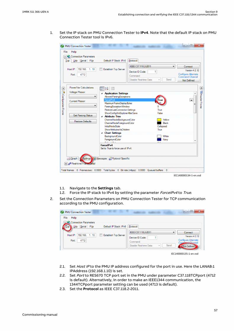
1. Set the IP stack on PMU Connection Tester to IPv4. Note that the default IP stack on PMUConnection Tester tool is IPv6.
IEC140000134-1-en.vsd
IEC140000134 V1 EN-US
1.1. Navigate to the Settings tab.1.2. Force the IP stack to IPv4 by setting the parameter ForceIPv4 to True.
2. Set the Connection Parameters on PMU Connection Tester for TCP communicationaccording to the PMU configuration.
IEC140000135-1-en.vsd
IEC140000135 V1 EN-US
2.1. Set Host IP to the PMU IP address configured for the port in use. Here the LANAB:1IPAddress (192.168.1.10) is set.
2.2. Set Port to RES670 TCP port set in the PMU under parameter C37.118TCPport (4712is default). Alternatively, in order to make an IEEE1344 communication, the1344TCPport parameter setting can be used (4713 is default).
2.3. Set the Protocol as IEEE C37.118.2-2011.
1MRK 511 366-UEN A Section 9Establishing connection and verifying the IEEE C37.118/1344 communication
57Commissioning manual
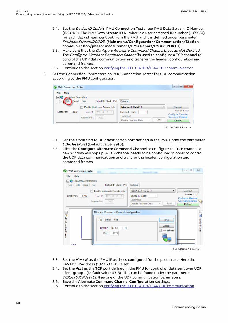
2.4. Set the Device ID Code in PMU Connection Tester per PMU Data Stream ID Number(IDCODE). The PMU Data Stream ID Number is a user assigned ID number (1-65534)for each data stream sent out from the PMU and it is defined under parameterPMUdataStreamIDCODE. (Main menu/Configuration/Communication/Stationcommunication/phasor measurement/PMU Report/PMUREPORT:1)
2.5. Make sure that the Configure Alternate Command Channel is set as Not Defined.The Configure Alternate Command Channel is used to configure a TCP channel tocontrol the UDP data communication and transfer the header, configuration andcommand frames.
2.6. Continue to the section Verifying the IEEE C37.118/1344 TCP communication.
3. Set the Connection Parameters on PMU Connection Tester for UDP communicationaccording to the PMU configuration.
IEC140000136-1-en.vsd
IEC140000136 V1 EN-US
3.1. Set the Local Port to UDP destination port defined in the PMU under the parameterUDPDestPort1 (Default value: 8910).
3.2. Click the Configure Alternate Command Channel to configure the TCP channel. Anew window will pop up. A TCP channel needs to be configured in order to controlthe UDP data communicatiuon and transfer the header, configuration andcommand frames.
IEC140000137-1-en.vsd
IEC140000137 V1 EN-US
3.3. Set the Host IP as the PMU IP address configured for the port in use. Here theLANAB:1 IPAddress (192.168.1.10) is set.
3.4. Set the Port as the TCP port defined in the PMU for control of data sent over UDPclient group 1 (Default value: 4713). This can be found under the parameterTCPportUDPdataCtrl1 as one of the UDP communication parameters.
3.5. Save the Alternate Command Channel Configuration settings.3.6. Continue to the section Verifying the IEEE C37.118/1344 UDP communication
Section 9 1MRK 511 366-UEN AEstablishing connection and verifying the IEEE C37.118/1344 communication
58Commissioning manual
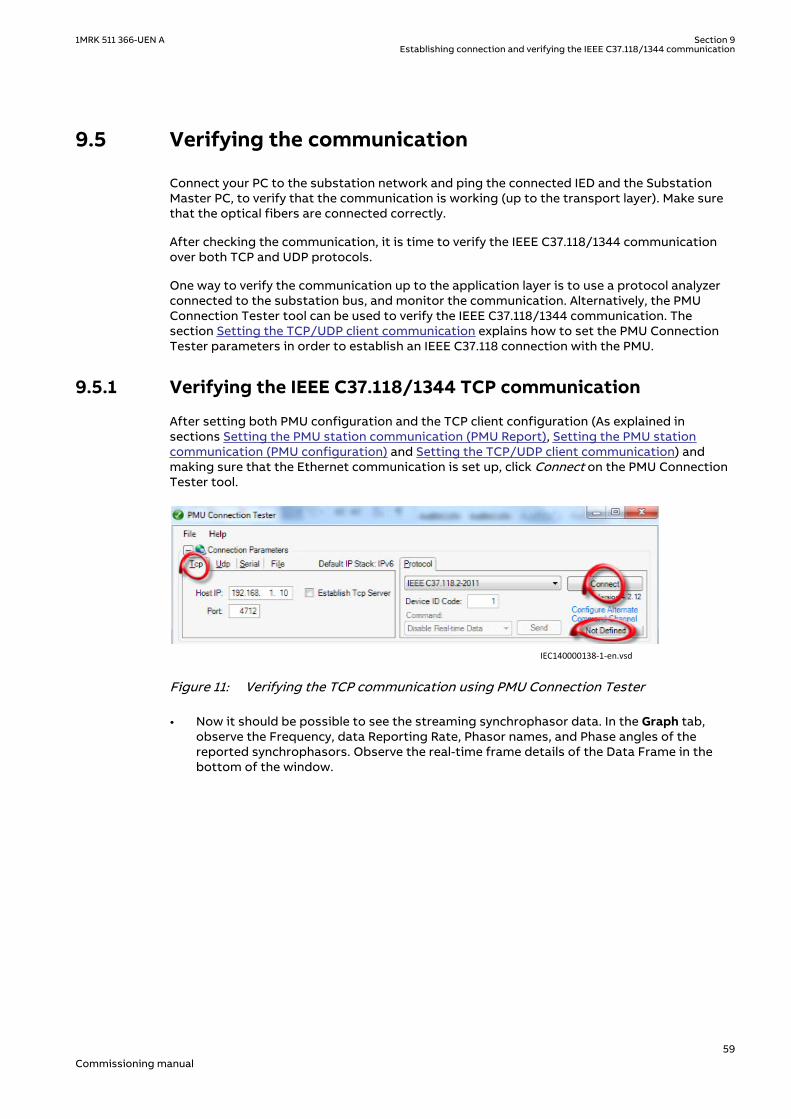
9.5 Verifying the communicationGUID-D10769FC-6C70-48A3-A1D8-FAFCCA82A3BE v2
Connect your PC to the substation network and ping the connected IED and the SubstationMaster PC, to verify that the communication is working (up to the transport layer). Make surethat the optical fibers are connected correctly.
After checking the communication, it is time to verify the IEEE C37.118/1344 communicationover both TCP and UDP protocols.
One way to verify the communication up to the application layer is to use a protocol analyzerconnected to the substation bus, and monitor the communication. Alternatively, the PMUConnection Tester tool can be used to verify the IEEE C37.118/1344 communication. Thesection Setting the TCP/UDP client communication explains how to set the PMU ConnectionTester parameters in order to establish an IEEE C37.118 connection with the PMU.
9.5.1 Verifying the IEEE C37.118/1344 TCP communicationGUID-289E2E92-431E-45FE-B586-A723588B98A1 v1
After setting both PMU configuration and the TCP client configuration (As explained insections Setting the PMU station communication (PMU Report), Setting the PMU stationcommunication (PMU configuration) and Setting the TCP/UDP client communication) andmaking sure that the Ethernet communication is set up, click Connect on the PMU ConnectionTester tool.
IEC140000138-1-en.vsdIEC140000138 V1 EN-US
Figure 11: Verifying the TCP communication using PMU Connection Tester
• Now it should be possible to see the streaming synchrophasor data. In the Graph tab,observe the Frequency, data Reporting Rate, Phasor names, and Phase angles of thereported synchrophasors. Observe the real-time frame details of the Data Frame in thebottom of the window.
1MRK 511 366-UEN A Section 9Establishing connection and verifying the IEEE C37.118/1344 communication
59Commissioning manual

IEC140000139-1-en.vsdIEC140000139 V1 EN-US
Figure 12: Graphic view over streaming synchrophasor data
• Open the drop-down menu in the Command field. There is a list of commands that can besent from the client (PMU Connection Tester) to the PMU. Try different commands andmake sure that the PMU is receiving and responding to them.
Section 9 1MRK 511 366-UEN AEstablishing connection and verifying the IEEE C37.118/1344 communication
60Commissioning manual

IEC140000140-1-en.vsdIEC140000140 V1 EN-US
Figure 13: Drop-down menu with commands for testing the PMU
• Switch to the Protocol Specific tab. Here, all the IEEE C37.118 message types can be seen.If the HeaderFrame is not included, ask the PMU to send the header frame via the SendHeader Frame command (Previous stage). Open each message type and observe thecontent of each message.
1MRK 511 366-UEN A Section 9Establishing connection and verifying the IEEE C37.118/1344 communication
61Commissioning manual

IEC140000141-1-en.vsdIEC140000141 V1 EN-US
Figure 14: All the IEEE C37.118 message types
• It is also possible to capture the IEEE C37.118 synchrophasor data in an Excel file. This isdone by navigating to File/Capture/Start Stream Debug Capture... The tool will ask toSet Stream Debug Capture File Name and path to save the capture file.
Section 9 1MRK 511 366-UEN AEstablishing connection and verifying the IEEE C37.118/1344 communication
62Commissioning manual

IEC140000142-1-en.vsdIEC140000142 V1 EN-US
Figure 15: Start capturing the IEEE C37.118 synchrophasor data
• The synchrophasor data capturing process can be stopped at any point of time bynavigating to File/Capture/Stop Stream Debug Capture...
1MRK 511 366-UEN A Section 9Establishing connection and verifying the IEEE C37.118/1344 communication
63Commissioning manual

IEC140000143-1-en.vsdIEC140000143 V1 EN-US
Figure 16: Stop capturing the IEEE C37.118 synchrophasor data
• Open the capture file and observe the captured synchrophasor data. In order to get thePhasor names on top of each column (See figure 17), the capture process should startbefore connecting the PMU Connection Tester to the PMU, i.e. first start the capturing andthen click Connect.
Section 9 1MRK 511 366-UEN AEstablishing connection and verifying the IEEE C37.118/1344 communication
64Commissioning manual

IEC140000144 V1 EN-US
Figure 17: Captured synchrophasor data
9.5.2 Verifying the IEEE C37.118/1344 UDP communicationGUID-F0D1117D-3D0F-498F-A00C-242763F8A4E6 v1
After setting both PMU configuration and the UDP client configuration (As explained insections Setting the PMU station communication (PMU Report), Setting the PMU stationcommunication (PMU configuration) and Setting the TCP/UDP client communication) andmaking sure that the Ethernet communication is set up, click Connect on the PMU ConnectionTester tool.
IEC140000145-1-en.vsdIEC140000145 V1 EN-US
Figure 18: Verifying the UDP communication using PMU Connection Tester
• Now it should be possible to see the streaming synchrophasor data.• Verify the communication by following the same steps as in section Verifying the IEEE
C37.118/1344 TCP communication.
1MRK 511 366-UEN A Section 9Establishing connection and verifying the IEEE C37.118/1344 communication
65Commissioning manual

9.6 Optical budget calculation for RES670 - PDCcommunication
GUID-F5DEACB1-4B83-4C68-B59A-694CAC78AF3D v2
Most of the times, the RES670 IEDs are located in the substations. A local PDC might belocated in the substation. For communications within the substation or between the RES670and the WAN/LAN access point, it is important to know what is the optical budget available.The graph in Figure 19 shows the dynamic range available for a PMU – PDC configuration usingtypical OEMs.
14
12
10
8
6
4
2
00 0.5 1.0 1.5 2.0 2.5 3.0 3.5 4.0
62.5/125 µm
50/125 µm
OPB
– O
PTIC
AL
POW
ER B
UD
GET
- dB
FIBER OPTIC CABLE LENGTH - km
IEC11000409_1_en.vsdIEC11000409 V1 EN-US
Figure 19: Optical power budget for fiber optic cable lengths
As shown in the graph, if one uses a 62.5/125 µm fiber, the value under the 62.5/125 µm curverepresents the remaining optical budget at any link length, which is available for overcomingnon-fiber cable related losses.
Losses in the connectors and splices are typically 0.3dB/connection. The user must reserve3dB spare for the uncertainty of the measurements.
Section 9 1MRK 511 366-UEN AEstablishing connection and verifying the IEEE C37.118/1344 communication
66Commissioning manual

Section 10 Testing IED operation
10.1 Preparing for testIP336-1 v1
10.1.1 RequirementsM11740-2 v8
IED test requirements:
• Calculated settings• Application configuration diagram• Signal matrix (SMT) configuration• Terminal connection diagram• Technical manual• Three-phase test equipment• Process bus, IEC61850-9-2LE, MU test simulator, if IEC 61850-9-2LE process bus
communication is used.• PCM600
The setting and configuration of the IED must be completed before the testing can start.
The terminal diagram, available in the technical reference manual, is a general diagram of theIED.
Note that the same diagram is not always applicable to each specific delivery(especially for the configuration of all the binary inputs and outputs).
Therefore, before testing, check that the available terminal diagram corresponds to the IED.
The technical manual contains application and functionality summaries, function blocks, logicdiagrams, input and output signals, setting parameters and technical data sorted perfunction.
The test equipment should be able to provide a three-phase supply of voltages and currents.The magnitude of voltage and current as well as the phase angle between voltage and currentmust be variable. The voltages and currents from the test equipment must be obtained fromthe same source and they must have minimal harmonic content. If the test equipment cannotindicate the phase angle, a separate phase-angle measuring instrument is necessary.
Prepare the IED for test before testing a particular function. Consider the logic diagram of thetested protection function when performing the test. All included functions in the IED aretested according to the corresponding test instructions in this chapter. The functions can betested in any order according to user preferences. Only the functions that are used (Operationis set to On) should be tested.
The response from a test can be viewed in different ways:
• Binary outputs signals• Service values on the local HMI (logical signals or phasors)• A PC with PCM600 application configuration software in work online mode
All setting groups that are used should be tested.
1MRK 511 366-UEN A Section 10Testing IED operation
67Commissioning manual

This IED is designed for a maximum continuous current of four times the ratedcurrent.
All references to CT and VT must be interpreted as analog values received frommerging units (MU) via IEC 61850-9-2LE communication protocol, analog valuesreceived from the transformer input module, or analog values received fromthe LDCM.
When using a MU test simulator, make sure it is set to the correct SVID and thatthe system frequency is set to the same as in the IED.
Please observe the measuring accuracy of the IED, the test equipment and theangular accuracy for both of them.
Please consider the configured logic from the function block to the outputcontacts when measuring the operate time.
After intense testing, it is important that the IED is not immediately restarted,which might cause a faulty trip due to flash memory restrictions. Some timemust pass before the IED is restarted. For more information about the flashmemory, refer to section “Configuring the IED and changing settings”.
10.1.2 Preparing the IED to verify settingsM11741-2 v11
If a test switch is included, start preparation by making the necessary connections to the testswitch. This means connecting the test equipment according to a specific and designated IEDterminal diagram.
Put the IED into the test mode to facilitate the test of individual functions and preventunwanted operation caused by other functions. The busbar differential protection is notincluded in the test mode and is not prevented to operate during the test operations. The testswitch should then be connected to the IED.
Verify that analog input signals from the analog input module are measured and recordedcorrectly by injecting currents and voltages required by the specific IED.
To make testing even more effective, use PCM600. PCM600 includes the Signal monitoringtool, which is useful in reading the individual currents and voltages, their amplitudes andphase angles. In addition, PCM600 contains the Disturbance handling tool. The content ofreports generated by the Disturbance handling tool can be configured which makes the workmore efficient. For example, the tool may be configured to only show time tagged events andto exclude analog information and so on.
Check the disturbance report settings to ensure that the indications are correct.
For information about the functions to test, for example signal or parameter names, see thetechnical manual. The correct initiation of the disturbance recorder is made on start and/or
Section 10 1MRK 511 366-UEN ATesting IED operation
68Commissioning manual
release or trip from a function. Also check that the wanted recordings of analog (real andcalculated) and binary signals are achieved.
Parameters can be entered into different setting groups. Make sure to testfunctions for the same parameter setting group. If needed, repeat the tests forall different setting groups used. The difference between testing the firstparameter setting group and the remaining is that there is no need for testingthe connections.
During testing, observe that the right testing method, that corresponds to the actualparameters set in the activated parameter setting group, is used.
Set and configure the function(s) before testing. Most functions are highly flexible and permita choice of functional and tripping modes. The various modes are checked at the factory aspart of the design verification. In certain cases, only modes with a high probability of cominginto operation need to be checked when commissioned to verify the configuration andsettings.
10.2 Activating the test modeM11412-2 v12
Put the IED into the test mode before testing. The test mode blocks all protection functionsand some of the control functions in the IED, and the individual functions to be tested can beunblocked to prevent unwanted operation caused by other functions. In this way, it is possibleto test slower back-up measuring functions without the interference from faster measuringfunctions. The test switch should then be connected to the IED.Test mode is indicated whenthe yellow StartLED flashes.
It is important that the IED function to be tested is put into test mode, even if the MU issending data marked as "test". The IED will interpret these data as valid if it is not in testmode.
1. Browse to the TestMode menu and press E.The TestMode menu is found on the local HMI under Main menu/Test/IED test mode/TestMode
2. Use the up and down arrows to choose On and press E.3. Press the left arrow to exit the menu.
The dialog box Save changes appears.4. Choose Yes, press E and exit the menu.
The yellow startLED above the LCD will start flashing when the IED is in test mode.
10.3 Preparing the connection to the test equipmentM11743-2 v8
The IED can be equipped with a test switch of type RTXP8, RTXP18 or RTXP24. The test switchand its associated test plug handle (RTXH8, RTXH18 or RTXH24) are a part of the COMBITESTsystem, which provides secure and convenient testing of the IED.
When using the COMBITEST, preparations for testing are automatically carried out in theproper sequence, that is, for example, blocking of tripping circuits, short circuiting of CTs,opening of voltage circuits, making IED terminals available for secondary injection. Terminals 1and 8, 1 and 18 as well as 1 and 12 of the test switches RTXP8, RTXP18 and RTXP24 respectivelyare not disconnected as they supply DC power to the protection IED.
The RTXH test-plug handle leads may be connected to any type of test equipment orinstrument. When a number of protection IEDs of the same type are tested, the test-plug
1MRK 511 366-UEN A Section 10Testing IED operation
69Commissioning manual
handle only needs to be moved from the test switch of one protection IED to the test switch ofthe other, without altering the previous connections.
Use COMBITEST test system to prevent unwanted tripping when the handle is withdrawn,since latches on the handle secure it in the half withdrawn position. In this position, allvoltages and currents are restored and any re-energizing transients are given a chance todecay before the trip circuits are restored. When the latches are released, the handle can becompletely withdrawn from the test switch, restoring the trip circuits to the protection IED.
If a test switch is not used, perform measurement according to the provided circuit diagrams.
Never disconnect the secondary connection of a current transformer circuitwithout first short-circuiting the transformer's secondary winding. Operating acurrent transformer with the secondary winding open will cause a massivepotential build up that may damage the transformer and cause personal injury.
10.4 Connecting the test equipment to the IEDM11744-2 v7
Connect the test equipment according to the IED specific connection diagram and the neededinput and output signals for the function under test. An example of a connection is shown infigure 20.
Connect the current and voltage terminals. Pay attention to the current polarity. Make surethat the connection of input and output current terminals and the connection of the residualcurrent conductor is correct. Check that the input and output logical signals in the logicdiagram for the function under test are connected to the corresponding binary inputs andoutputs of the IED under test.
The MU test equipment must be connected to the CD port on the OEM modulewhen process bus IEC61850-9-2LE communication is used.
To ensure correct results, make sure that the IED as well as the test equipmentare properly earthed before testing.
Section 10 1MRK 511 366-UEN ATesting IED operation
70Commissioning manual

IL1IL2IL3IN
UL1UL2UL3UN
IL1IL2IL3
UL1
IN (I4,I5)
TRIP L1TRIP L2TRIP L3
Test
equ
ipm
ent
IED
IEC09000652-1-en.vsd
UL2UL3UNUN (U4,U5)
IEC 61850
IEC09000652 V1 EN-US
Figure 20: Connection example of the test equipment to the IED when test equipment isconnected to the transformer input module
10.5 Releasing the function to be testedM11413-2 v6
Release or unblock the function to be tested. This is done to ensure that only the function orthe chain of functions to be tested are in operation and that other functions are preventedfrom operating. Release the tested function(s) by setting the corresponding Blockedparameter under Function test modes to No in the local HMI.
When testing a function in this blocking feature, remember that not only the actual functionmust be activated, but the whole sequence of interconnected functions (from measuringinputs to binary output contacts), including logic must be activated. Before starting a new testmode session, scroll through every function to ensure that only the function to be tested (andthe interconnected ones) have the parameters Blocked and eventually EvDisable set to No andYes respectively. Remember that a function is also blocked if the BLOCK input signal on thecorresponding function block is active, which depends on the configuration. Ensure that thelogical status of the BLOCK input signal is equal to 0 for the function to be tested. Eventfunction blocks can also be individually blocked to ensure that no events are reported to aremote station during the test. This is done by setting the parameter EvDisable to Yes.
Any function is blocked if the corresponding setting in the local HMI under Mainmenu/Test/Function test modes menu remains On, that is, the parameterBlocked is set to Yes and the parameter TestMode under Main menu/Test/IEDtest mode remains active. All functions that were blocked or released in aprevious test mode session, that is, the parameter Test mode is set to On, arereset when a new test mode session is started.
Procedure
1. Click the Function test modes menu.The Function test modes menu is located in the local HMI under Main menu/Test/Function test modes.
2. Browse to the function instance that needs to be released.3. Set parameter Blocked for the selected function to No.
1MRK 511 366-UEN A Section 10Testing IED operation
71Commissioning manual

10.6 Verifying analog primary and secondary measurementM11745-2 v13
Verify that the connections are correct and that measuring and scaling is done correctly. Thisis done by injecting current and voltage to the IED.
Besides verifying analog input values from the merging unit via the IEC/UCA 61850-9-2LEprocess bus, analog values from the transformer input module can be verified as follows.
Apply input signals as needed according to the actual hardware and theapplication configuration.
1. Inject a symmetrical three-phase voltage and current at rated value.2. Compare the injected value with the measured values.
The voltage and current phasor menu in the local HMI is located under Main menu/Measurements/Analog primary values and Main menu/Measurements/Analogsecondary values.
3. Compare the frequency reading with the set frequency and the direction of the power.The frequency and active power are located under Main menu/Measurements/Monitoring/ServiceValues(MMXN)/CVMMXN:x. Then navigate to the bottom of the listto find the frequency.
4. Inject an unsymmetrical three-phase voltage and current, to verify that phases arecorrectly connected.
If some setting deviates, check the analog input settings under
Main menu/Configuration/Analog modules
If the IEC/UCA 61850-9-2LE communication is interrupted during currentinjection, the report tool in PCM600 will display the current that was injectedbefore the interruption.
Section 10 1MRK 511 366-UEN ATesting IED operation
72Commissioning manual

IEC10000032-1-en.vsdIEC10000032 V1 EN-US
Figure 21: PCM600 report tool display after communication interruption
10.7 Testing the protection functionalityGUID-125B6F28-D3E5-4535-9CD6-6C056B79F496 v2
Each protection function must be tested individually by secondary injection.
• Verify operating levels (trip) and timers.• Verify alarm and blocking signals.• Use the disturbance handling tool in PCM600 to evaluate that the protection function has
received the correct data and responded correctly (signaling and timing).• Use the event viewer tool in PCM600 to check that only expected events have occurred.
10.8 Forcing of binary I/O signals for testing
10.8.1 Forcing conceptGUID-3FD8C676-10E5-432A-8CD5-4643299AD794 v1
Forcing of binary inputs and outputs is a convenient way to test wiring in substations as wellas testing configuration logic in the IEDs. Basically it means that all binary inputs and outputson the IED I/O modules (BOM, BIM, IOM & SOM) can be set to a value (i.e active or not-active),selected by the user, while the IED is in test mode. For inputs, this is true regardless of theactual signal voltage present on the input. For outputs, any output relay can be forced to beactive or not, regardless of the current requested state of the output in the IED logicconfiguration.
Be observant that forcing of binary inputs and outputs on an IED, withinappropriate setup, can result in potential danger.
1MRK 511 366-UEN A Section 10Testing IED operation
73Commissioning manual

10.8.2 How to enable forcingGUID-50280F59-A98C-4E48-AB6D-2B4C138943DD v1
To enable forcing, the IED must first be put into IED test mode. While the IED is not in testmode, the LHMI/PCM600 menus that relate to forcing will not have any effect on the input/output status due to safety reasons.
10.8.2.1 Enable forcing by using LHMIGUID-41F7C636-75BC-42EF-A955-4BD9E347619E v1
1. Enable IED Testmode by setting IEDTestMode to On under Main menu/Test/IED testmode TESTMODE:1.
IEC15000029 V1 EN-US
2. Exit back to the root menu.3. Select Yes in the save dialogue box.
Once the IED is in test mode the yellow Start LED starts to blink.
10.8.2.2 Enable forcing using TESTMODE function blockGUID-DD17B7D6-516F-4561-9D30-906B968EAFE0 v1
• Use the TESTMODE function block, appropriately configured in PCM600/ACT.
It may be convenient to control the input on mentioned component from, for example, an LHMIfunction key or similar during commissioning to quickly and easily enter IED test mode.
10.8.3 How to change binary input/output signals using forcingGUID-7DF9FAF1-68B1-49AF-9DE4-2A8D6F6FAEFE v1
Once the IED is in IED test mode, the LHMI/PCM600 menus can be used to control input/output signals freely.
10.8.3.1 Forcing by using LHMIGUID-D885671F-79E5-4B75-8777-B59E44F6FCFC v1
Editing a signal value directlyGUID-E0C115BE-3AD1-48C7-BA2D-29857CD3D3ED v1
• Edit the input/output value directly to select the desired logical level, by doing following:
1. Select the value line of the desired signal, see figure 22.2. Press the Enter key to edit the value.
Section 10 1MRK 511 366-UEN ATesting IED operation
74Commissioning manual
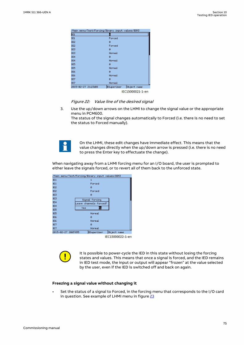
IEC15000021 V1 EN-US
Figure 22: Value line of the desired signal
3. Use the up/down arrows on the LHMI to change the signal value or the appropriatemenu in PCM600.The status of the signal changes automatically to Forced (i.e. there is no need to setthe status to Forced manually).
On the LHMI, these edit changes have immediate effect. This means that thevalue changes directly when the up/down arrow is pressed (i.e. there is no needto press the Enter key to effectuate the change).
When navigating away from a LHMI forcing menu for an I/O board, the user is prompted toeither leave the signals forced, or to revert all of them back to the unforced state.
IEC15000022 V1 EN-US
It is possible to power-cycle the IED in this state without losing the forcingstates and values. This means that once a signal is forced, and the IED remainsin IED test mode, the input or output will appear “frozen” at the value selectedby the user, even if the IED is switched off and back on again.
Freezing a signal value without changing itGUID-FD76AAC1-7098-47D3-A3A1-6ACDF509ED91 v1
• Set the status of a signal to Forced, in the forcing menu that corresponds to the I/O cardin question. See example of LHMI menu in figure 23
1MRK 511 366-UEN A Section 10Testing IED operation
75Commissioning manual

IEC15000020 V1 EN-US
Figure 23: Example of LHMI menu using BIM3
The signal “freezes” and will not change value even if, for example, a binary input signal voltagechanges level, or if a binary output is activated as the result of a protection function blockactivating.
10.8.3.2 Forcing by using PCM600GUID-E9D0DAE6-7A86-4FF9-943E-42039015D05B v1
In PCM600 the concept is a bit different compared to LHMI. The forcing is accomplished byentering a forcing session. Within such a session, multiple signals on multiple I/O boards maybe edited and changed at the same time and has no effect on the IED. Once the user issatisfied with the forcing setup, then all the changes can be effectuated simultaneouslytowards the IED, potentially changing inputs and outputs on multiple I/O boards at the sametime. It is also possible to abort this operation (described in step 6 below) and to undo allforcing.
1. Right click on the IED in the plant structure and select Signal Monitoring.2. Click on the List View tab.3. Click Forcing Session in the menu IED/Start Forcing.
IEC15000023 V1 EN-US
4. Click Start editing signal value for forcing on the tool bar.
IEC15000024 V1 EN-US
The Signal Monitoring menu changes and indicates the forcing values that can be edited.
Section 10 1MRK 511 366-UEN ATesting IED operation
76Commissioning manual

IEC15000025 V1 EN-US
5. Select and edit the values.6. Click Acknowledge and send.
IEC15000026 V1 EN-US
This commits the values to the IED and exits the editing session.7. Click Cancel to abort the changes and revert back to actual IED values.
IEC15000032 V1 EN-US
Regardless if the forcing changes are commited or canceled, the forcing is stillactive.
To force more signals, click the button Start editing signal value for forcing again.
10.8.4 How to undo forcing changes and return the IED to normaloperation
GUID-00E2BAD8-A29E-4B9D-80E6-E12F59E019BD v1
Regardless of which input/output signals have been forced, all forced signals will return totheir normal states immediately when the IED is taken out of test mode.
When the forcing is removed by exiting from IED test mode, both input andoutput signals may change values. This means that logic input signals mayactivate functions in the IED and that output relays may change state, whichcan be potentially dangerous.
1MRK 511 366-UEN A Section 10Testing IED operation
77Commissioning manual

10.8.4.1 Undo forcing by using TestMode componentGUID-CA5CCA57-DFFF-4362-AC1D-08738D2BA45F v1
• If the IED test mode was entered through the test mode function block:
1. Deactivate the control input on that block.
This immediately undoes all forcing, regardless of how it was accomplished and disabledall the way to force signals.
10.8.4.2 Undo forcing by using LHMIGUID-55199606-E70D-49B1-885D-251700FB562B v1
• If the IED test mode was enabled to using the LHMI:
1. Set IEDTestMode to Off in the LHMI menu.2. Exit from the menu and click Yes in the Save dialogue box.
This immediately undoes all forcing, regardless of how it was accomplished and disabled.
10.8.4.3 Undo forcing by using PCM600GUID-CE7FD186-99FC-41C8-910F-894A57037777 v1
1. Uncheck Forcing Session under the menu IED.
IEC15000031 V1 EN-US
2. Click Yes in the confirmation dialogue box.PCM600 will revert all forced signals back to unforced and the real signal values willimmediately take effect again.
This may change both binary input values and output relay states and will undoany forcing done by using the LHMI.If the IED is left in test mode, then it is still possible to perform new forcingoperations, both from LHMI and from PCM600
Section 10 1MRK 511 366-UEN ATesting IED operation
78Commissioning manual

Section 11 Testing functionality by secondaryinjection
11.1 Testing disturbance report
11.1.1 IntroductionM17101-2 v6
The following sub-functions are included in the disturbance report function:
• Disturbance recorder• Event list• Event recorder• Trip value recorder• Indications
If the disturbance report is set on, then its sub-functions are also set up and so it is notpossible to only switch these sub-functions off. The disturbance report function is switchedoff (parameter Operation = Off) in PCM600 or the local HMI under Main menu/Settings/IEDSettings/Monitoring/Disturbance report/DRPRDRE:1.
11.1.2 Disturbance report settingsM11746-2 v6
When the IED is in test mode, the disturbance report can be made active or inactive. If thedisturbance recorder is turned on during test mode, recordings will be made. When test modeis switched off all recordings made during the test session are cleared.
Setting OpModeTest for the control of the disturbance recorder during test mode are locatedon the local HMI under Main menu/Settings/IED Settings/Monitoring/Disturbance report/DRPRDRE:1.
11.1.3 Disturbance recorder (DR)M11750-2 v6
A Manual Trig can be started at any time. This results in a recording of the actual values fromall recorded channels.
The Manual Trig can be started in two ways:
1. From the local HMI under Main menu/Disturbance records.
1.1. Enter on the row at the bottom of the HMI called Manual trig.A new recording begins. The view is updated if you leave the menu and return.
1.2. Navigate to General information or to Trip values to obtain more detailedinformation.
2. Open the Disturbance handling tool for the IED in the plant structure in PCM600.
2.1. Right-click and select Execute manual Trig in the window Available recordings in IED.2.2. Read the required recordings from the IED.2.3. Refresh the window Recordings and select a recording.2.4. Right-click and select Create Report or Open With to export the recordings to any
disturbance analyzing tool that can handle Comtrade formatted files.
1MRK 511 366-UEN A Section 11Testing functionality by secondary injection
79Commissioning manual

Evaluation of the results from the disturbance recording function requires access to a PCeither permanently connected to the IED or temporarily connected to the Ethernet port (RJ-45)on the front. The PCM600 software package must be installed in the PC.
Disturbance upload can be performed by the use of PCM600 or by any third party tool with IEC61850 protocol. Reports can automatically be generated from PCM600. Disturbance files canbe analyzed by any tool reading Comtrade formatted disturbance files.
It could be useful to have a printer for hard copies. The correct start criteria and behavior ofthe disturbance recording function can be checked when IED protective functions are tested.
When the IED is brought into normal service it is recommended to delete all recordings, madeduring commissioning to avoid confusion in future fault analysis.
All recordings in the IED can be deleted in two ways:
1. in the local HMI under Main menu/Clear/Reset disturbances, or2. in the Disturbance handling tool in PCM600 by selecting Delete all recordings in the IED...
in the window Available Recordings in IED.
11.1.4 Event recorder (ER) and Event list (EL)M12645-2 v6
The result from the event recorder and event list can be viewed on the local HMI or, afterupload, in PCM600 as follows:
1. on the local HMI under Main menu/Events, or in more details via2. the Event Viewer in PCM600.
The internal FIFO register of all events will appear when the event viewer is launched.
When the IED is brought into normal service it is recommended to delete all events resultingfrom commissioning tests to avoid confusion in future fault analysis. All events in the IED canbe cleared in the local HMI under Main Menu//Clear/Clear internal event list or Main menu/Clear/Clear process event list. It is not possible to clear the event lists from PCM600.
When testing binary inputs, the event list (EL) might be used instead. No uploading oranalyzing of registrations is then needed since the event list keeps running, independent ofstart of disturbance registration.
11.2 Identifying the function to test in the technicalreference manual
M11748-2 v4
Use the technical manual to identify function blocks, logic diagrams, input and output signals,setting parameters and technical data.
11.3 SEMOD53525-1 v2
11.3.1 M13888-2 v9
Impedance protection
Power swing detection ZMRPSB
The aim is to verify that the settings of the Power swing detection function ZMRPSB is according to the setting table and to verify that ZMRPSB operates as expected.
Prepare the IED for verification of settings outlined in section "Requirements" and section "Preparing for test" in this chapter.
Section 11 1MRK 511 366-UEN ATesting functionality by secondary injection
80Commissioning manual

Before starting this process, all impedance measuring zones shall be set and in operation. Testthe outer resistive boarder in forward and reverse direction, RLdOutFw and RLdOutRv and theinner reactive boarder in forward and reverse direction X1InFw and X1InRv. See figure 24.
The corresponding resistive border for the inner resistive boundary and outer resistiveboundary is calculated automatically from the setting of kLdRFw and kLdRRv.
The inner zone of ZMRPSB must cover all zones by at least 10% margin.
The test is mainly divided into two parts, one which aim is to verify that the settings are inaccordance to the selectivity plan and a second part to verify the operation of ZMRPSB. Theproposed test points for validation of the settings are numbered according to figure 24
Test of the interactions or combinations that are not configured are not considered in thisinstruction.
X1OutRv
ZL
j jR
XX1OutFwX1InFw
1RLdOutFw
RLdInFw
RLdOutRv
RLdInRv
2
3
4X1InRv
IEC09000226_1_en.vsdIEC09000226 V1 EN-US
Figure 24: Operating principle and characteristic of the power swing detection function(settings parameters in italic)
Where:
RLdInFw = RLdOutFw · kLdRFw
RLdInRv = RLdOutRv · kLdRRv
X1OutFw = X1InFw + (RLdOutFw - RLdInFw)
X1OutRv = X1InRv + (RLdOutFw - RLdInFw)
11.3.1.1 Verifying the settingsM13888-11 v6
Preconditions
1MRK 511 366-UEN A Section 11Testing functionality by secondary injection
81Commissioning manual

The following output signal shall be configured to binary output available: ZOUT, measuredimpedance within outer impedance boundary.
1. Keep the measured current as close as possible to its rated value or lower. Keep itconstant during the test, but ensure that it is higher than the set minimum operatingcurrent.
2. Ensure that the maximum continuous current to the IED does not exceed four times itsrated value, if the measurement of the operating characteristics runs under constantvoltage conditions.
3. Make the necessary connections and settings of the test equipment for test of point 1according to figure 24.
4. Decrease the measured three-phase impedance slowly and observe the operation valuefor the signal ZOUT.
5. Compare the operation value with the set value.6. Do the necessary change of the setting of the test equipment and repeat step 4 and step
5 for point 2, 3 and 4 according to figure 24.
11.3.1.2 Testing the power swing detection function ZMRPSBM13888-27 v6
Preconditions
The following output signals shall be configured to binary outputs: ZOUT, measuredimpedance within outer impedance boundary, ZIN, measured impedance within innerimpedance boundary and START, power swing detection.
1. Slowly decrease the measured impedance in all three phases until the START signal getsactivated.
2. Increase the measured voltages to their rated values.3. Decrease instantaneously voltages in all three phases to the values, which are
approximately 20% lower than the voltage that gives the set value R1LIn at thepredefined test current.
4. The START signal must not appear.5. Increase the measured voltages to their rated values.
11.3.1.3 Testing the tR1 timerM13888-47 v8
Preconditions
• The input I0CHECK, residual current (3I0) detection used to inhibit the start output mustbe configured to the output signal STPE on the FDPSPDIS or FRPSPDIS function.
• The input BLKI02, block inhibit of the start output for subsequent residual currentdetection is connected to FALSE.
1. Program the test equipment for a single-phase to earth fault and energize FDPSPDIS orFRPSDIS and check that the input BLOCK on the power swing detection function ZMRPSBis activated.
2. Make a test sequence so that a single-phase to earth fault occurs after that the trajectoryof the impedance has passed the outer and inner boundary of ZMRPSB during powerswing. Use the result from test of ZMRPSB above to determine when the fault shall beapplied. The earth-fault must be activated before tR1 has elapsed.
3. Start the sequence and observe that the START signal will not be activated.
Section 11 1MRK 511 366-UEN ATesting functionality by secondary injection
82Commissioning manual

11.3.1.4 Testing the block input, interaction between FDPSPDIS or FRPSPDIS andZMRPSB
M13888-73 v7
Precondition
The BLOCK input is configured and connected to STPE output on the FDPSPDIS or FRPSPDISfunction.
1. Make a test sequence so that a single phase-to-earth-fault occurs after that thetrajectory of the impedance has passed the outer boundary but not the inner boundaryof the power swing detection function ZMRPSB. Use the result from test of ZMRPSBabove to instance when the fault shall be applied.
2. Start the test sequence by continuously reducing the voltage and observe that theoutput signal ZOUT may come, but not START.If the input I0CHECK is configured (connected to output signal STPE on FDPSPDIS orFRPSPDIS, the test of inhibit of ZMRPSB at earth-fault during power swing can be done inthe same way as for test of tR1. The inhibit of ZMRPSB shall be instantaneous if the inputTRSP is activated at the same time as the input I0CHECK during power swing.
11.3.1.5 Completing the testM13888-99 v5
Continue to test another function or end the test by changing the TestMode setting to Off.Restore connections and settings to their original values, if they were changed for testingpurposes.
11.3.2 Out-of-step protection OOSPPAMGUID-BF2F7D4C-F579-4EBD-9AFC-7C03296BD5D4 v7
The out-of-step protection OOSPPAM function in the IED can be used for both generatorprotection and as well for line protection applications.
The main purpose of the OOSPPAM function is to detect, evaluate, and take the requiredaction during pole slipping occurrences in the power system.
The OOSPPAM function detects pole slip conditions and trips the generator as fast aspossible, after the first pole-slip if the center of oscillation is found to be in zone 1, whichnormally includes the generator and its step-up power transformer. If the center of oscillationis found to be further out in the power system, in zone 2, more than one pole-slip is usuallyallowed before the generator-transformer unit is disconnected. A parameter setting isavailable to take into account the circuit breaker opening time. If there are several out-of-steprelays in the power system, then the one which finds the center of oscillation in its zone 1should operate first.
Two current channels I3P1 and I3P2 are available in OOSPPAM function to allow the directconnection of two groups of three-phase currents; that may be needed for very powerfulgenerators, with stator windings split into two groups per phase, when each group isequipped with current transformers. The protection function performs a simple summation ofthe currents of the two channels I3P1 and I3P2.
11.3.2.1 Verifying the settingsGUID-708C4033-3111-481F-9868-FF207C18C9F9 v1
The test of the out-of-step protection function is made to verify that the trip is issued if thefollowing events happen.
• the impedance, seen by the function, enters the lens characteristic from one side andleaves it from the opposite side
• the trip is issued according to the settings TripAngle and tBreaker
1MRK 511 366-UEN A Section 11Testing functionality by secondary injection
83Commissioning manual

The tripping zone needs to be detected and confirmed. The test may be performed by takinginto account the following key points that are shown in Figure 25:
• the point RE (RE = Receiving End)• the intersection between the line segment SE-RE and the X-line, which is defined through
the setting ReachZ1• the point SE (SE = Sending End)
I = I(50 Hz) + I(49.5 Hz)
IEC10000141 V2 EN-US
Figure 25: Trajectory of the impedance Z(R, X) for the injected current with twocomponents: a 50 Hz component and a 49.5 Hz current component
The test of the out-of-step protection function requires the injection of the analog quantitiesfor a quite long time. The rating of the analogue channels is considered in order to avoid anyhardware damage. The test current is lower than the continuous permissive overload currentIovrl of the protection current channels of the transformer module.
If the rated secondary current Irs of the analog channel is 1 A, then the maximum current test Itsis
I I I Ats ovrl rs
≤ = × =4 4
EQUATION14041 V1 EN-US (Equation 1)
If the CT of the generator has ratio 9000/1 A, then in primary values
I I II
IA
t ovrl p ovrl
rp
rs
≤ = × = × =,
49000
136000
EQUATION14042 V1 EN-US (Equation 2)
Reference is made to the numerical values of the example, explained in the “Setting guidelines”of the Application Manual. A test current equal to 2.5 time the base current of the generator ischosen; this choice is related to the selected test voltage that is applied while testing the pointSE and RE.
I I At Base= × = × =2 5 2 5 8367 20918. .
EQUATION14043 V1 EN-US (Equation 3)
The parameter ReachZ1 defines the boundary between zone 1 and zone 2; it is expressed inpercent of the parameter ForwardX. If the setting of ReachZ1 = 12%, then correspondingprimary value of the reactance is
Section 11 1MRK 511 366-UEN ATesting functionality by secondary injection
84Commissioning manual
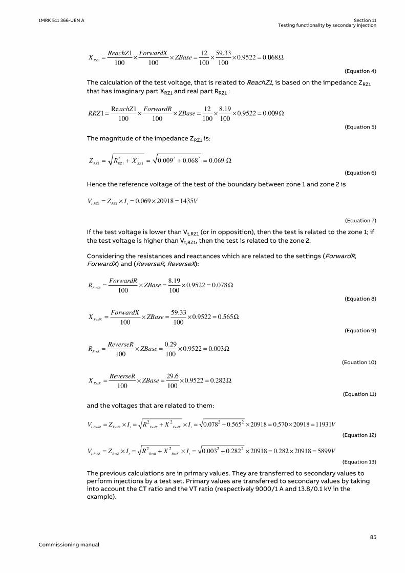
XReachZ ForwardX
ZBaseRZ1
1
100 100
12
100
59 33
1000 9522 0= × × = × × =
.. .0068Ω
EQUATION14044 V1 EN-US (Equation 4)
The calculation of the test voltage, that is related to ReachZ1, is based on the impedance ZRZ1that has imaginary part XRZ1 and real part RRZ1 :
RRZachZ ForwardR
ZBase11
100 100
12
100
8 19
1000 9522 0 0= × × = × × =
Re .. . 009Ω
EQUATION14045 V1 EN-US (Equation 5)
The magnitude of the impedance ZRZ1 is:
2 2 2 21 1 1 0.009 0.068 0.069 RZ RZ RZZ R X= + = + = W
EQUATION14046 V1 EN-US (Equation 6)
Hence the reference voltage of the test of the boundary between zone 1 and zone 2 is
V Z I Vt RZ RZ t,
.1 1
0 069 20918 1435= × = × =
EQUATION14047 V1 EN-US (Equation 7)
If the test voltage is lower than Vt,RZ1 (or in opposition), then the test is related to the zone 1; ifthe test voltage is higher than Vt,RZ1, then the test is related to the zone 2.
Considering the resistances and reactances which are related to the settings (ForwardR,ForwardX) and (ReverseR, ReverseX):
RForwardR
ZBaseFwdR
= × = × =
100
8 19
1000 9522 0 078
.. . Ω
EQUATION14048 V1 EN-US (Equation 8)
XForwardX
ZBaseFwdX
= × = × =
100
59 33
1000 9522 0 565
.. . Ω
EQUATION14049 V1 EN-US (Equation 9)
RReverseR
ZBaseRvsR
= × = × =
100
0 29
1000 9522 0 003
.. . Ω
EQUATION14050 V1 EN-US (Equation 10)
XReverseR
ZBaseRvsX
= × = × =
100
29 6
1000 9522 0 282
.. . Ω
EQUATION14051 V1 EN-US (Equation 11)
and the voltages that are related to them:
V Z I R X It FwdZ FwdZ t FwdR FwdX t,
. . .= × = + × = + × =2 2 2 2
0 078 0 565 20918 0 5700 20918 11931× = V
EQUATION14052 V1 EN-US (Equation 12)
V Z I R X It RvsZ RvsZ t RvsR RvsX t,
. . .= × = + × = + × =2 2 2 2
0 003 0 282 20918 0 2822 20918 5899× = V
EQUATION14053 V1 EN-US (Equation 13)
The previous calculations are in primary values. They are transferred to secondary values toperform injections by a test set. Primary values are transferred to secondary values by takinginto account the CT ratio and the VT ratio (respectively 9000/1 A and 13.8/0.1 kV in theexample).
1MRK 511 366-UEN A Section 11Testing functionality by secondary injection
85Commissioning manual

The magnitude of the secondary voltages, that are related to the points RE and SE of the R-Xplane, needs to be checked.
RE (RFwdR, XFwdX):
V VV
VV
t FwdZs t FwdZ
VT s
VT p
, ,
,
,
.
..= × = × =11931
0 1
13 886 45
EQUATION14054 V1 EN-US (Equation 14)
SE (RRvsR, XRvsX):
V VV
VV
t RvsZs t RvsZ
VT s
VT p
, ,
,
,
.
..= × = × =5899
0 1
13 842 75
EQUATION14055 V1 EN-US (Equation 15)
The tests, which are described in this section, may require voltages that have magnitude equalto 110% of the previous values. The continuous permissive overload voltage of the protectionvoltage channels of the TRM module is 420 V; so the previous voltages may be applied to theanalog channels of the IED continuously. Limitations may be related to the available test set;the current It was calculated by using a factor 2.5 (instead of the maximum value 4) in order toreduce the magnitude of the test voltage for the points RE and SE.
Test sets usually do not have a feature to simulate a real network during a power swing andapply the related analog quantities at the terminal of the generator. The scope of the presenttest is not a simulation of a real network. Voltages and currents are supplied in order tomeasure an impedance that changes in the time and traverses the plane R-X and, in particular,the area inside the lens characteristic. The test may be performed by applying:
• Symmetric three-phase voltage at 50 Hz. The magnitude depends on the point of thecharacteristic that needs to be verified. The following three main points of the linesegment SE-RE need to be checked:
• the point RE (RFwdR, XFwdX)• a point which is related to the parameter ReachZ1 (boundary between zone 1 and
zone 2)• the point SE (RRvsR, XRvsX)
The phase angle of the test voltages is equal to:
• arctan (ForwardX/ForwardR) for tests in the quadrant 1 and 2 of the R-X plane• arctan (ReverseX/ReverseR) -180° for tests in the quadrant 3 and 4 of the R-X plane
• Symmetric three-phase current, where the current is the summation of two currents thathave the same magnitude, but different frequencies.
I I Atf
tI
502
20918
2
10459= = = =
GUID-F02E8D18-FF87-45BE-8142-E8FA19F6966B V1 EN-US (Equation 16)
The first current I50 has frequency 50 Hz, magnitude 10459 A (that is, 1.162 A secondary)and phase angle 0º.The second current Itf has magnitude 10459 A (that is, 1.162 A secondary), phase angle180º (at the starting time of the test) and frequency:
• 49.5 Hz for the test as generator in the quadrant 1 and 2 of the R-X plane• 50.5 Hz for the test as generator in the quadrant 3 and 4 of the R-X plane
Section 11 1MRK 511 366-UEN ATesting functionality by secondary injection
86Commissioning manual

When the trajectory of the impedance, that is seen by the protection function,traverses the lens characteristic then a pole slipping is detected. The presentprocedure avoids tests of points of the line SE-RE that are too close to the R-axis because in that case the voltage is close to zero and, therefore, theimpedance may approach a not defined quantity 0/0.
The accuracy of the impedance reach is ±2% of the base impedance; that isconsidered while evaluating the test results.
For the test as motor the frequency current may have 50.5 Hz in the quadrant 1and 2 of the R-X plane and 49.5 Hz in the quadrant 3 and 4.
Verifying the settings by secondary injectionGUID-1752CE04-7C0F-4D37-9602-B22D8096DD2D v1
It is advised to connect the analog output channels of the function block OOSPPAM to theinternal disturbance recorder (and in particular to the function block A4RADR) in order toperform a better analysis of the tests.
If the device is in test mode, the recording of the disturbances are enabled by the setting inMain menu/Settings/IED Settings/Monitoring/Disturbance report/DisturbanceReport/DRPRDRE:1: set the parameter OpModeTest to On.
1. Check the Application Configuration: verify that hardware voltage and current channels ofthe IED are properly connected to SMAI function blocks, and that the proper analogoutputs of SMAI’s are connected to the analog inputs of the function block OOSPPAM.
2. Connect three-phase voltage channels of the test set to the appropriate IED terminals.3. Connect in parallel two groups of three-phase currents of the test set to the appropriate
IED terminals.4. Connect the appropriate trip output of the IED to the input channel of the test set that
monitors the trip.5. Go to Main menu/Settings/IED Settings/Impedance protection/OutOfStep(78,Ucos)/
OOSPPAM(78,Ucos):1, and make sure that the function is enabled, that is, Operation is setto On.
11.3.2.2 Test of point RE (RFwdR, XFwdX)GUID-911D370F-8767-4D6C-9621-8663DD26006C v1
The trajectory of the impedance does not enter the lens characteristic.GUID-5C5E9BEB-AA60-474E-ACEC-B972ACFE6FA2 v1
Preliminary steady state test at 50 HzGUID-8F95CCCC-3282-48E8-9F5E-3F3E77CCCAAE v1
• Go to Main menu/Test/Function status/Impedance protection/OutOfStep(78,Ucos)/OOSPPAM(78,Ucos):1/Outputs to check the available service values of the function blockOOSPPAM.
• Apply the following three-phase symmetrical quantities (the phase angle is related tophase L1):
V VV
VV
ts t FwdZ
VT s
VT p
= × × = × × =1 1 1 1 119310 1
13 895 1. .
.
..
,
,
,
EQUATION14057 V1 EN-US (Equation 17)
∠ =
=
=V
ForwardX
ForwardRts
arctan arctan.
.
59 33
8 1982..14°
EQUATION14058 V1 EN-US (Equation 18)
1MRK 511 366-UEN A Section 11Testing functionality by secondary injection
87Commissioning manual

frequency of Vts = 50 Hz
I II
IA
s
CTs
CTp
50 5010459
1
90001 162= × = × = .
EQUATION14059 V1 EN-US (Equation 19)
∠I50s=0°frequency of I50s = 50 Hz
It II
IA
fs
CTs
CTp
tf= × = × =104591
90001 162.
EQUATION14062 V1 EN-US (Equation 20)
∠Itfs=0°frequency of Itfs = 50 Hz
• Check that the service values (VOLTAGE, CURRENT, R(%), X(%)) are according to theinjected quantities and that ROTORANG is close to 0 rad.For this particular injection the service values are:
• VOLTAGE = 13.12 kV• CURRENT = 20918 A• R = 9.01%• X = 65.27%• ROTORANG = 0.04 rad
Note that these values identify a point outside the lens characteristic, even if it is close to thepoint RE. Neither START nor TRIP is issued.
Execution of the dynamic testGUID-0B73C849-107D-40DC-80BB-31CD441BF69A v1
The test may be performed by using two states of a sequence tool that is a basic feature oftest sets.
• State 1: pre-test condition.Steady voltage and current are applied in order to get a steady high impedance. This is apoint in the plane R-X that is far away from the lens characteristic. Define the followingthree-phase symmetrical quantities (the phase angle is related to phase L1):
V VV
VV
ts t FwdZ
VT s
VT p
= × × = × × =1 1 1 1 119310 1
13 895 1. .
.
..
,
,
,
EQUATION14057 V1 EN-US (Equation 21)
∠ =
=
=V
ForwardX
ForwardRts
arctan arctan.
.
59 33
8 1982..14°
EQUATION14058 V1 EN-US (Equation 22)
frequency of Vts = 50 HzI50s=0 AItfs=0 A
• State 2: main test step.Define the following three-phase symmetrical quantities (the phase angle is related tophase L1):
V VV
VV
ts t FwdZ
VT s
VT p
= × × = × × =1 1 1 1 119310 1
13 895 1. .
.
..
,
,
,
EQUATION14057 V1 EN-US (Equation 23)
Section 11 1MRK 511 366-UEN ATesting functionality by secondary injection
88Commissioning manual

∠ =
=
=V
ForwardX
ForwardRts
arctan arctan.
.
59 33
8 1982..14°
EQUATION14058 V1 EN-US (Equation 24)
frequency of Vts = 50 Hz
I II
IA
s
CTs
CTp
50 5010459
1
90001 162= × = × = .
EQUATION14059 V1 EN-US (Equation 25)
∠I50s = 0ºfrequency of I50s = 50 Hz
It II
IA
fs
CTs
CTp
tf= × = × =104591
90001 162.
EQUATION14062 V1 EN-US (Equation 26)
∠Itfs = 180ºfrequency of Itfs = 49.5 Hz Expected result: the protection function does not issue either start or trip.
The trajectory of the impedance traverses the lens characteristic in zone 2GUID-9F0FE404-6D83-4308-9FE4-13259CE7D07A v1
Preliminary steady state test at 50 HzGUID-700F4EA1-B7D9-4B77-829A-433BB67C8A01 v1
• Go to Main menu/Test/Function status/Impedance protection/OutOfStep(78,Ucos)/OOSPPAM(78,Ucos):1/Outputs to check the available service values of the function blockOOSPPAM.
• Apply the following three-phase symmetrical quantities (the phase angle is related tophase L1):
V VV
VV
ts t FwdZ
VT s
VT p
= × × = × × =0 9 0 9 119310 1
13 877 81. .
.
..
,
,
,
EQUATION14063 V1 EN-US (Equation 27)
∠ =
=
=V
ForwardX
ForwardRts
arctan arctan.
.
59 33
8 1982..14°
EQUATION14058 V1 EN-US (Equation 28)
frequency of Vts = 50 Hz
I II
IA
s
CTs
CTp
50 5010459
1
90001 162= × = × = .
EQUATION14059 V1 EN-US (Equation 29)
∠I50s = 0ºfrequency of I50s = 50 Hz
It II
IA
fs
CTs
CTp
tf= × = × =104591
90001 162.
EQUATION14062 V1 EN-US (Equation 30)
∠Itfs = 0ºfrequency of Itf = 50 Hz
1MRK 511 366-UEN A Section 11Testing functionality by secondary injection
89Commissioning manual

• Check that the service values (VOLTAGE, CURRENT, R(%), X(%) ) are according to theinjected quantities and that ROTORANG is close to 3.14 rad. For this particular injectionthe service values are:
• VOLTAGE = 10.74 kV• CURRENT = 20918 A• R = 7.37%• X = 53.40%• ROTORANG = -3.09 rad
Note that these values identify a point inside the lens characteristic, in the zone 2, that isclose to the point RE. The START is issued, but no TRIP is performed.
Execution of the dynamic testGUID-028D7D67-B61A-4A7F-9978-4A0A41231B04 v1
The test may be performed by using two states of a sequence tool that is a basic feature oftest sets.
• State 1: pre-test condition.Steady voltage and current are applied in order to get a steady high impedance, that is, apoint in the plane R-X which is far away from the lens characteristic. Define the followingthree-phase symmetrical quantities (the phase angle is related to phase L1):
V VV
VV
ts t FwdZ
VT s
VT p
= × × = × × =0 9 0 9 119310 1
13 877 81. .
.
..
,
,
,
EQUATION14063 V1 EN-US (Equation 31)
∠ =
=
=V
ForwardX
ForwardRts
arctan arctan.
.
59 33
8 1982..14°
EQUATION14058 V1 EN-US (Equation 32)
frequency of Vts = 50 HzI50s = 0 AItfs = 0 A
• State 2: main test step.Define the following three-phase symmetrical quantities (the phase angle is related tophase L1):
V VV
VV
ts t FwdZ
VT s
VT p
= × × = × × =0 9 0 9 119310 1
13 877 81. .
.
..
,
,
,
EQUATION14063 V1 EN-US (Equation 33)
∠ =
=
=V
ForwardX
ForwardRts
arctan arctan.
.
59 33
8 1982..14°
EQUATION14058 V1 EN-US (Equation 34)
frequency of Vts = 50 Hz
I II
IA
s
CTs
CTp
50 5010459
1
90001 162= × = × = .
EQUATION14059 V1 EN-US (Equation 35)
∠I50s = 0ºfrequency of I50s = 50 Hz
It II
IA
fs
CTs
CTp
tf= × = × =104591
90001 162.
EQUATION14062 V1 EN-US (Equation 36)
Section 11 1MRK 511 366-UEN ATesting functionality by secondary injection
90Commissioning manual
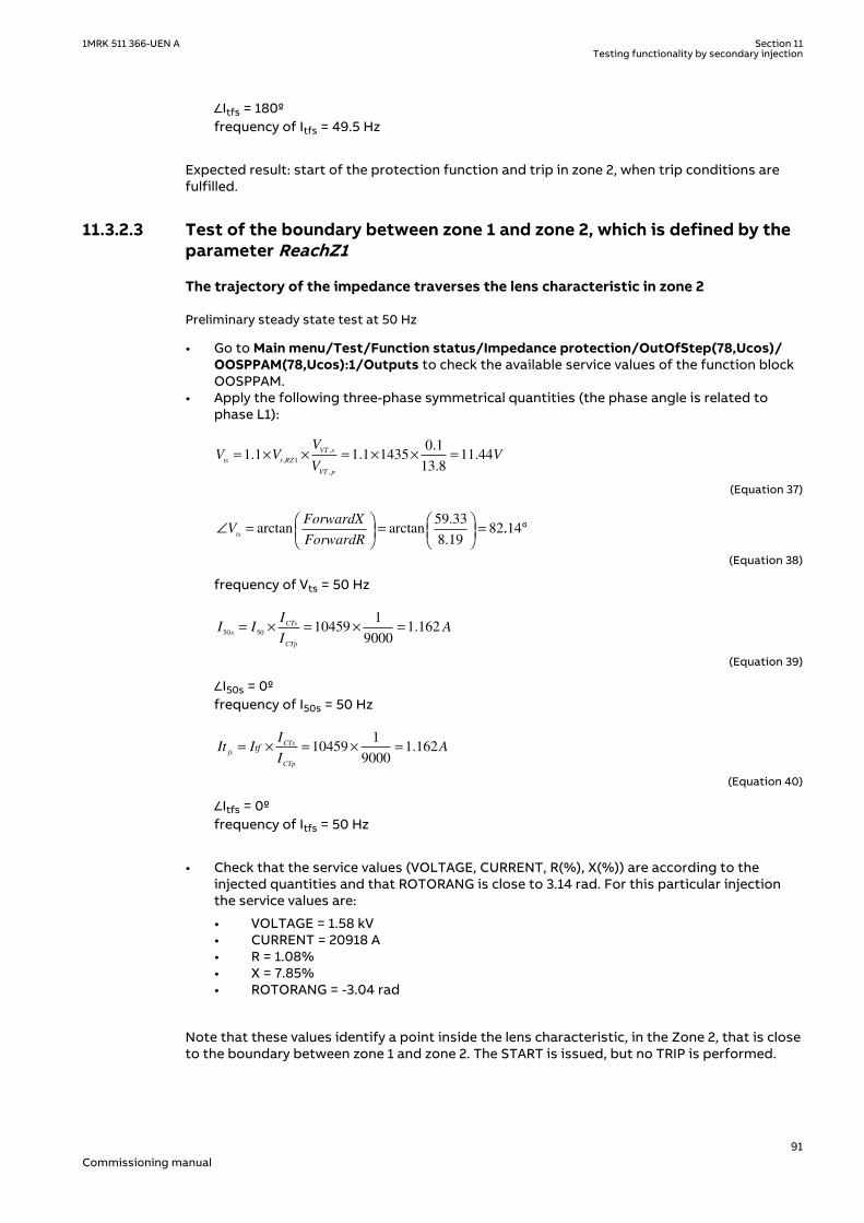
∠Itfs = 180ºfrequency of Itfs = 49.5 Hz
Expected result: start of the protection function and trip in zone 2, when trip conditions arefulfilled.
11.3.2.3 Test of the boundary between zone 1 and zone 2, which is defined by theparameter ReachZ1
GUID-BE180E07-7D4B-4842-81FB-244DE8897430 v1
The trajectory of the impedance traverses the lens characteristic in zone 2GUID-17F6AC8D-1F57-4245-A61D-776D469DD153 v1
Preliminary steady state test at 50 HzGUID-3D42E43D-873E-4271-9AAF-3B2789FF3B17 v1
• Go to Main menu/Test/Function status/Impedance protection/OutOfStep(78,Ucos)/OOSPPAM(78,Ucos):1/Outputs to check the available service values of the function blockOOSPPAM.
• Apply the following three-phase symmetrical quantities (the phase angle is related tophase L1):
V VV
VV
ts t RZ
VT s
VT p
= × × = × × =1 1 1 1 14350 1
13 811 44
1. .
.
..
,
,
,
EQUATION14065 V1 EN-US (Equation 37)
∠ =
=
=V
ForwardX
ForwardRts
arctan arctan.
.
59 33
8 1982..14°
EQUATION14058 V1 EN-US (Equation 38)
frequency of Vts = 50 Hz
I II
IA
s
CTs
CTp
50 5010459
1
90001 162= × = × = .
EQUATION14059 V1 EN-US (Equation 39)
∠I50s = 0ºfrequency of I50s = 50 Hz
It II
IA
fs
CTs
CTp
tf= × = × =104591
90001 162.
EQUATION14062 V1 EN-US (Equation 40)
∠Itfs = 0ºfrequency of Itfs = 50 Hz
• Check that the service values (VOLTAGE, CURRENT, R(%), X(%)) are according to theinjected quantities and that ROTORANG is close to 3.14 rad. For this particular injectionthe service values are:
• VOLTAGE = 1.58 kV• CURRENT = 20918 A• R = 1.08%• X = 7.85%• ROTORANG = -3.04 rad
Note that these values identify a point inside the lens characteristic, in the Zone 2, that is closeto the boundary between zone 1 and zone 2. The START is issued, but no TRIP is performed.
1MRK 511 366-UEN A Section 11Testing functionality by secondary injection
91Commissioning manual

Execution of the dynamic testGUID-53964189-42E4-4C4B-BFCD-64888BA938EF v1
The test may be performed by using two states of a sequence tool that is a basic feature oftest sets.
• State 1: pre-test condition.Steady voltage and current are applied in order to get a steady high impedance, that is apoint in the plane R-X that is far away from the lens characteristic. Define the followingthree-phase symmetrical quantities (the phase angle is related to phase L1):
V VV
VV
ts t RZ
VT s
VT p
= × × = × × =1 1 1 1 14350 1
13 811 44
1. .
.
..
,
,
,
EQUATION14065 V1 EN-US (Equation 41)
∠ =
=
=V
ForwardX
ForwardRts
arctan arctan.
.
59 33
8 1982..14°
EQUATION14058 V1 EN-US (Equation 42)
frequency of Vt= 50 Hz.I50s = 0 AItfs = 0 A
• State 2: main test step.Define the following three-phase symmetrical quantities (the phase angle is related tophase L1):
V VV
VV
ts t RZ
VT s
VT p
= × × = × × =1 1 1 1 14350 1
13 811 44
1. .
.
..
,
,
,
EQUATION14065 V1 EN-US (Equation 43)
∠ =
=
=V
ForwardX
ForwardRts
arctan arctan.
.
59 33
8 1982..14°
EQUATION14058 V1 EN-US (Equation 44)
frequency of Vt = 50 Hz
I II
IA
s
CTs
CTp
50 5010459
1
90001 162= × = × = .
EQUATION14059 V1 EN-US (Equation 45)
∠I50s = 0ºfrequency of I50s = 50 Hz
It II
IA
fs
CTs
CTp
tf= × = × =104591
90001 162.
EQUATION14062 V1 EN-US (Equation 46)
∠Itfs = 180ºfrequency of Itfs = 49.5 Hz Expected result: start of the protection function and trip in zone 2 when trip conditionsare fulfilled.
Section 11 1MRK 511 366-UEN ATesting functionality by secondary injection
92Commissioning manual

The trajectory of the impedance traverses the lens characteristic in zone 1GUID-12F82DD8-A4CE-48C9-944B-0CF3B3F6C9F9 v1
Preliminary steady state test at 50 HzGUID-AA953F5F-2389-4F05-8BBD-D8DC9AF3B0E4 v1
• Go to Main menu/Test/Function status/Impedance protection/OutOfStep(78,Ucos)/OOSPPAM(78,Ucos):1/Outputs to check the available service values of the function blockOOSPPAM.
• Apply the following three-phase symmetrical quantities (the phase angle is related tophase L1):
V VV
VV
ts t RZ
VT s
VT p
= × × = × × =0 9 0 9 14350 1
13 89 36
1. .
.
..
,
,
,
EQUATION14066 V1 EN-US (Equation 47)
∠ =
=
=V
ForwardX
ForwardRts
arctan arctan.
.
59 33
8 1982..14°
EQUATION14058 V1 EN-US (Equation 48)
frequency of Vts = 50 Hz
I II
IA
s
CTs
CTp
50 5010459
1
90001 162= × = × = .
EQUATION14059 V1 EN-US (Equation 49)
∠I50s = 0ºfrequency of I50s = 50 Hz
It II
IA
fs
CTs
CTp
tf= × = × =104591
90001 162.
EQUATION14062 V1 EN-US (Equation 50)
∠Itfs = 0ºfrequency of Itf = 50 Hz
• Check that the service values (VOLTAGE, CURRENT, R(%), X(%)) are according to theinjected quantities and that ROTORANG is close to 3.14 rad. For this particular injectionthe service values are:
• VOLTAGE = 1.29 kV• CURRENT = 20918 A• R = 0.89%• X=6.42%• ROTORANG = -3.04 rad
Note that these values identify a point inside the lens characteristic in zone 1, that is closeto the boundary between zone 1 and zone 2. The START is issued, but no TRIP isperformed.
Execution of the dynamic testGUID-98707DB3-9A1A-4458-9704-25F8FCB94B79 v1
The test may be performed by using two states of a sequence tool that is a basic feature oftest sets.
• State 1: pre-test condition.Steady voltage and current are applied in order to get a steady high impedance, that is apoint in the plane R-X which is far away from the lens characteristic. Define the followingthree-phase symmetrical quantities (the phase angle is related to phase L1):
1MRK 511 366-UEN A Section 11Testing functionality by secondary injection
93Commissioning manual

V VV
VV
ts t RZ
VT s
VT p
= × × = × × =0 9 0 9 14350 1
13 89 36
1. .
.
..
,
,
,
EQUATION14066 V1 EN-US (Equation 51)
∠ =
=
=V
ForwardX
ForwardRts
arctan arctan.
.
59 33
8 1982..14°
EQUATION14058 V1 EN-US (Equation 52)
frequency of Vts = 50 HzI50s = 0 AItfs = 0 A
• State 2: main test step.Define the following three-phase symmetrical quantities (the phase angle is related tophase L1):
V VV
VV
ts t RZ
VT s
VT p
= × × = × × =0 9 0 9 14350 1
13 89 36
1. .
.
..
,
,
,
EQUATION14066 V1 EN-US (Equation 53)
∠ =
=
=V
ForwardX
ForwardRts
arctan arctan.
.
59 33
8 1982..14°
EQUATION14058 V1 EN-US (Equation 54)
frequency of Vts = 50 Hz
I II
IA
s
CTs
CTp
50 5010459
1
90001 162= × = × = .
EQUATION14059 V1 EN-US (Equation 55)
∠I50s = 0ºfrequency of I50s = 50 Hz
It II
IA
fs
CTs
CTp
tf= × = × =104591
90001 162.
EQUATION14062 V1 EN-US (Equation 56)
∠Itfs = 180ºfrequency of Itfs = 49.5 Hz Expected result: start of the protection function and trip in zone 1 when trip conditionsare fulfilled.
11.3.2.4 Test of the point SE (RRvsR, XRvsX)GUID-335F54E6-52DE-4BF1-A34B-0C2DB8059CC1 v1
The trajectory of the impedance traverses the lens characteristic in zone 1GUID-2DD20D2E-6188-4631-A584-5E68B212E011 v1
Preliminary steady state test at 50 HzGUID-7BCF3D7B-1B84-46D4-B9E3-066894A878E8 v1
• Go to Main menu/Test/Function status/Impedance protection/OutOfStep(78,Ucos)/OOSPPAM(78,Ucos):1/Outputs to check the available service values of the function blockOOSPPAM.
• Apply the following three-phase symmetrical quantities (the phase angle is related tophase L1):
Section 11 1MRK 511 366-UEN ATesting functionality by secondary injection
94Commissioning manual

V VV
VV
ts t RvsZ
VT s
VT p
= × × = × × =0 9 0 9 58990 1
13 838 47. .
.
..
,
,
,
EQUATION14067 V1 EN-US (Equation 57)
29.60arctan 180 arctan 180 90.56
0.29ts
ReverseXV
ReverseRÐ = - ° = - ° = - °æ ö æ ö
ç ÷ ç ÷è ø è ø
EQUATION14068 V1 EN-US (Equation 58)
frequency of Vts = 50 Hz
I II
IA
s
CTs
CTp
50 5010459
1
90001 162= × = × = .
EQUATION14059 V1 EN-US (Equation 59)
∠I50s = 0ºfrequency of I50s = 50 Hz
It II
IA
fs
CTs
CTp
tf= × = × =104591
90001 162.
EQUATION14062 V1 EN-US (Equation 60)
∠Itfs = 0ºfrequency of Itf = 50 Hz
• Check that the service values (VOLTAGE, CURRENT, R(%), X(%)) are according to theinjected quantities and that ROTORANG is close to 3.14 rad. For this particular injectionthe service values are:
• VOLTAGE = 5.31 kV• CURRENT = 20918 A• R = -0.26%• X = -26.65%• ROTORANG = -3.06 rad
Note that these values identify a point inside the lens characteristic in zone 1 that is closeto the point SE. The START is issued, but no TRIP is performed.
Execution of the dynamic testGUID-FF6DCD5B-96AA-4255-8740-B85C8C7148F5 v1
The test may be performed by using two states of a sequence tool that is a basic feature oftest sets.
• State 1: pre-test condition.Steady voltage and current are applied in order to get a steady high impedance, that is apoint in the plane R-X which is far away from the lens characteristic. Define the followingthree-phase symmetrical quantities (the phase angle is related to phase L1):
V VV
VV
ts t RvsZ
VT s
VT p
= × × = × × =0 9 0 9 58990 1
13 838 47. .
.
..
,
,
,
EQUATION14067 V1 EN-US (Equation 61)
29.60arctan 180 arctan 180 90.56
0.29ts
ReverseXV
ReverseRÐ = - ° = - ° = - °æ ö æ ö
ç ÷ ç ÷è ø è ø
EQUATION14068 V1 EN-US (Equation 62)
frequency of Vts = 50 HzI50s = 0 AItfs = 0 A
1MRK 511 366-UEN A Section 11Testing functionality by secondary injection
95Commissioning manual
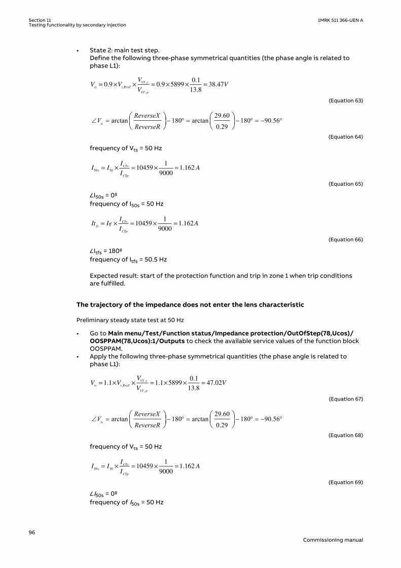
• State 2: main test step.Define the following three-phase symmetrical quantities (the phase angle is related tophase L1):
V VV
VV
ts t RvsZ
VT s
VT p
= × × = × × =0 9 0 9 58990 1
13 838 47. .
.
..
,
,
,
EQUATION14067 V1 EN-US (Equation 63)
29.60arctan 180 arctan 180 90.56
0.29ts
ReverseXV
ReverseRÐ = - ° = - ° = - °æ ö æ ö
ç ÷ ç ÷è ø è ø
EQUATION14068 V1 EN-US (Equation 64)
frequency of Vts = 50 Hz
I II
IA
s
CTs
CTp
50 5010459
1
90001 162= × = × = .
EQUATION14059 V1 EN-US (Equation 65)
∠I50s = 0ºfrequency of I50s = 50 Hz
It II
IA
fs
CTs
CTp
tf= × = × =104591
90001 162.
EQUATION14062 V1 EN-US (Equation 66)
∠Itfs = 180ºfrequency of Itfs = 50.5 Hz Expected result: start of the protection function and trip in zone 1 when trip conditionsare fulfilled.
The trajectory of the impedance does not enter the lens characteristicGUID-189FECED-12A7-4A41-BCCF-D93C0FF9FA41 v1
Preliminary steady state test at 50 HzGUID-448D5357-6CC2-438E-83CA-25FD381B7DFF v1
• Go to Main menu/Test/Function status/Impedance protection/OutOfStep(78,Ucos)/OOSPPAM(78,Ucos):1/Outputs to check the available service values of the function blockOOSPPAM.
• Apply the following three-phase symmetrical quantities (the phase angle is related tophase L1):
V VV
VV
ts t RvsZ
VT s
VT p
= × × = × × =1 1 1 1 58990 1
13 847 02. .
.
..
,
,
,
EQUATION14069 V1 EN-US (Equation 67)
29.60arctan 180 arctan 180 90.56
0.29ts
ReverseXV
ReverseRÐ = - ° = - ° = - °æ ö æ ö
ç ÷ ç ÷è ø è ø
EQUATION14068 V1 EN-US (Equation 68)
frequency of Vts = 50 Hz
I II
IA
s
CTs
CTp
50 5010459
1
90001 162= × = × = .
EQUATION14059 V1 EN-US (Equation 69)
∠I50s = 0ºfrequency of I50s = 50 Hz
Section 11 1MRK 511 366-UEN ATesting functionality by secondary injection
96Commissioning manual

It II
IA
fs
CTs
CTp
tf= × = × =104591
90001 162.
EQUATION14062 V1 EN-US (Equation 70)
∠Itfs = 0ºfrequency of Itf = 50 Hz
• Check that the service values (VOLTAGE, CURRENT, R(%), X(%)) are according to theinjected quantities and that ROTORANG is close to 0 rad. For this particular injection theservice values are:
• VOLTAGE= 6.49 kV• CURRENT= 20918 A• R= –0.32%• X=–32.57%• ROTORANG= 0.08 rad
Note that these values identify a point outside the lens characteristic, even if it is close tothe point SE. Neither START nor TRIP is issued.
Execution of the dynamic testGUID-31EF4F76-8FC8-4952-896C-B3A8A5FD635A v1
The test may be performed by using two states of a sequence tool that is a basic feature oftest sets.
• State 1: pre-test condition.Steady voltage and current are applied in order to get a steady high impedance, that is, apoint in the plane R-X which is far away from the lens characteristic. Define the followingthree-phase symmetrical quantities (the phase angle is related to phase L1):
V VV
VV
ts t RvsZ
VT s
VT p
= × × = × × =1 1 1 1 58990 1
13 847 02. .
.
..
,
,
,
EQUATION14069 V1 EN-US (Equation 71)
29.60arctan 180 arctan 180 90.56
0.29ts
ReverseXV
ReverseRÐ = - ° = - ° = - °æ ö æ ö
ç ÷ ç ÷è ø è ø
EQUATION14068 V1 EN-US (Equation 72)
frequency of Vts = 50 HzI50s = 0 AItfs = 0 A
• State 2: main test step.Define the following three-phase symmetrical quantities (the phase angle is related tophase L1):
V VV
VV
ts t RvsZ
VT s
VT p
= × × = × × =1 1 1 1 58990 1
13 847 02. .
.
..
,
,
,
EQUATION14069 V1 EN-US (Equation 73)
29.60arctan 180 arctan 180 90.56
0.29ts
ReverseXV
ReverseRÐ = - ° = - ° = - °æ ö æ ö
ç ÷ ç ÷è ø è ø
EQUATION14068 V1 EN-US (Equation 74)
frequency of Vts = 50 Hz
1MRK 511 366-UEN A Section 11Testing functionality by secondary injection
97Commissioning manual

I II
IA
s
CTs
CTp
50 5010459
1
90001 162= × = × = .
EQUATION14059 V1 EN-US (Equation 75)
∠I50s = 0ºfrequency of I50s = 50 Hz
It II
IA
fs
CTs
CTp
tf= × = × =104591
90001 162.
EQUATION14062 V1 EN-US (Equation 76)
∠Itfs = 180ºfrequency of Itfs = 50.5 Hz Expected result: the protection function does not issue either start or trip.
GUID-7C9F1163-0186-41DA-9D5F-DDA589323B9F v1
After each test it is possible to download and study the related disturbance recording.
IEC10000142-1-en.vsd
012
COMMON TRIP COMMAND (trip)
-101
TRIPZ1 (tripZone1)
012
TRIPZ2 (tripZone2)
012
START (start)
012
GENMODE (generatorMode)
0 0.5 1 1.5 2 2.5 3 3.5 4 4.5 5-101
time in seconds →
MOTMODE (motorMode)
IEC10000142 V1 EN-US
Figure 26: Boolean output signals for the injected current with two components: a 50 Hzcurrent component and a 49.5 Hz current component
Section 11 1MRK 511 366-UEN ATesting functionality by secondary injection
98Commissioning manual

11.4 Current protectionSEMOD53531-1 v1
11.4.1 Four step phase overcurrent protection 3-phase outputOC4PTOC
SEMOD56287-67 v7
Prepare the IED for verification of settings as outlined in section "Requirements" andsection "Preparing for test" in this chapter.
11.4.1.1 Verifying the settingsSEMOD56287-72 v9
Verification of the non-directional phase overcurrent function is done asinstructed below, without applying any polarizing voltage.
1. Connect the test set for current injection to the appropriate IED phases.If there is any configuration logic that is used to enable or block any of the four availableovercurrent steps, make sure that the step under test is enabled (for example, end faultprotection).If 1 out of 3 currents for operation is chosen: Connect the injection current to phases L1and neutral.If 2 out of 3 currents for operation is chosen: Connect the injection current into phase L1and out from phase L2.If 3 out of 3 currents for operation is chosen: Connect the symmetrical three-phaseinjection current into phases L1, L2 and L3.
2. Connect the test set for the appropriate three-phase voltage injection to the IED phasesL1, L2 and L3. The protection shall be fed with a symmetrical three-phase voltage.
3. Block higher set stages when testing lower set stages by following the proceduredescribed below:
3.1. Set the injected polarizing voltage slightly larger than the set minimum polarizingvoltage (default is 5% of UBase) and set the injection current to lag the appropriatevoltage by an angle of about 80° if forward directional function is selected.If 1 out of 3 currents for operation is chosen: The voltage angle of phase L1 is thereference.If 2 out of 3 currents for operation is chosen: The voltage angle of phase L1 – thevoltage angle of L2 is the reference.If 3 out of 3 currents for operation is chosen: The voltage angle of phase L1 is thereference.If reverse directional function is selected, set the injection current to lag thepolarizing voltage by an angle equal to 260° (equal to 80° + 180°).
3.2. Increase the injected current, note the operate value of the tested step of thefunction and compare it to the set value.
3.3. Decrease the current slowly, note the reset value and compare it to the reset ratio95%.
4. If the test has been performed by injection of current in phase L1, repeat the test,injecting current into phases L2 and L3 with polarizing voltage connected to phases L2,respectively L3 (1 out of 3 currents for operation).
5. If the test has been performed by injection of current in phases L1 – L2, repeat the test,injecting current into phases L2 – L3 and L3 – L1 with the appropriate phase angle ofinjected currents.
6. Connect a trip output contact to a timer.7. Set the injected current to 200% of the operate level of the tested stage, switch on the
current and check the time delay.
1MRK 511 366-UEN A Section 11Testing functionality by secondary injection
99Commissioning manual

For inverse time curves, check the operate time at a current equal to 110% of the operatecurrent for txMin.
8. Check that all operate and start contacts operate according to the configuration (signalmatrixes).
9. Reverse the direction of the injected current and check that the protection does notoperate.
10. If 2 out of 3 or 3 out of 3 currents for operation is chosen: Check that the function will notoperate with current in one phase only.
11. Repeat the above described tests for the higher set stages.12. Check that start and trip information is stored in the event menu.
11.4.1.2 Completing the testSEMOD56287-118 v4
Continue to test another function or end the test by changing the TestMode setting to Off.Restore connections and settings to their original values, if they were changed for testingpurposes.
11.4.2 Four step residual overcurrent protection, (Zero sequence ornegative sequence directionality) EF4PTOC
SEMOD53296-3 v8
Prepare the IED for verification of settings as outlined in section "Requirements" andsection "Preparing for test" in this chapter.
11.4.2.1 Four step directional earth fault protectionSEMOD53296-208 v6
1. Connect the test set for single current injection to the appropriate IED terminals.Connect the injection current to terminals L1 and neutral.
2. Set the injected polarizing voltage slightly larger than the set minimum polarizing voltage(default 5% of Ur) and set the injection current to lag the voltage by an angle equal to theset reference characteristic angle (AngleRCA), if the forward directional function isselected.If reverse directional function is selected, set the injection current to lag the polarizingvoltage by an angle equal to RCA+ 180°.
3. Increase the injected current and note the value at which the studied step of the functionoperates.
4. Decrease the current slowly and note the reset value.5. If the test has been performed by injection of current in phase L1, repeat the test,
injecting current into terminals L2 and L3 with a polarizing voltage connected toterminals L2, respectively L3.
6. Block lower set steps when testing higher set steps according to the instructions thatfollow.
7. Connect a trip output contact to a timer.8. Set the injected current to 200% of the operate level of the tested step, switch on the
current and check the time delay.For inverse time curves, check the operate time at a current equal to 110% of the operatecurrent for txMin.
9. Check that all operate and start contacts operate according to the configuration (signalmatrixes)
10. Reverse the direction of the injected current and check that the step does not operate.11. Check that the protection does not operate when the polarizing voltage is zero.12. Repeat the above described tests for the higher set steps.13. Finally, check that start and trip information is stored in the event menu.
Section 11 1MRK 511 366-UEN ATesting functionality by secondary injection
100Commissioning manual

11.4.2.2 Four step non-directional earth fault protectionSEMOD53296-202 v4
1. Do as described in "Four step directional earth fault protection", but without applyingany polarizing voltage.
11.4.2.3 Completing the testSEMOD53296-122 v4
Continue to test another function or end the test by changing the TestMode setting to Off.Restore connections and settings to their original values, if they were changed for testingpurposes.
11.4.3 Four step negative sequence overcurrent protection NS4PTOCGUID-EB1A8DFD-5BAC-4024-ADA2-D9BE7A2B50A0 v1
Prepare the IED for verification of settings as outlined in section "Requirements" andsection "Preparing for test" in this chapter.
GUID-F7AA2194-4D1C-4475-8853-C7D064912614 v4
When inverse time overcurrent characteristic is selected, the operate time ofthe stage will be the sum of the inverse time delay and the set definite timedelay. Thus, if only the inverse time delay is required, it is important to set thedefinite time delay for that stage to zero.
GUID-F973601F-BC67-4E4F-A4CA-BE6253E2FB92 v3
Procedure
1. Connect the test set for injection of three-phase currents and voltages to theappropriate CT and VT inputs of the IED.
2. Inject pure negative sequence current, that is, phase currents with exactly samemagnitude, reversed sequence and exactly 120° phase displaced into the IED with aninitial value below negative sequence current pickup level. No output signals should beactivated. Check under NS4PTOC function Service Values that correct I2 magnitude ismeasured by the function.
3. Set the injected negative sequence polarizing voltage slightly larger than the setminimum polarizing voltage (default 5 % of Ub) and set the injection current to lag thevoltage by an angle equal to the set reference characteristic angle (180° - AngleRCA) if theforward directional function is selected.If reverse directional function is selected, set the injection current to lag the polarizingvoltage by an angle equal to RCA.
4. Increase the injected current and note the value at which the studied step of the functionoperates.
5. Decrease the current slowly and note the reset value.6. Block lower set steps when testing higher set steps according to the instructions that
follow.7. Connect a trip output contact to a timer.8. Set the injected current to 200% of the operate level of the tested step, switch on the
current and check the time delay.For inverse time curves, check the operate time at a current equal to 110% of the operatecurrent in order to test parameter txmin.
9. Check that all operate and start contacts operate according to the configuration (signalmatrixes)
10. Reverse the direction of the injected current and check that the step does not operate.11. Check that the protection does not operate when the polarizing voltage is zero.12. Repeat the above-described tests for the higher set steps.13. Finally, check that start and trip information is stored in the event menu.
1MRK 511 366-UEN A Section 11Testing functionality by secondary injection
101Commissioning manual

11.4.3.1 Completing the testSEMOD53296-122 v4
Continue to test another function or end the test by changing the TestMode setting to Off.Restore connections and settings to their original values, if they were changed for testingpurposes.
11.4.4 Sensitive directional residual overcurrent and powerprotection SDEPSDE
SEMOD175060-3 v7
Prepare the IED for verification of settings as outlined in section "Requirements" andsection "Preparing for test" in this chapter.
IEC09000021-2-en.vsd
IED test set
NI
IED
NI
L1UL2UL3U
NU
U1U2U3
NU
TRIP
IEC09000021 V2 EN-US
Figure 27: Principle connection of the test set
Values of the logical signals belonging to the sensitive directional residual overcurrent andpower protection are available on the local HMI under Main menu/Test/Function status/Current protection/SensDirResOvCurr(67N,IN>)/SDEPSDE(67N,IN>):x
11.4.4.1 Measuring the operate and time limit for set valuesSEMOD175060-12 v2
Operation mode 3I0 · cosφSEMOD175060-34 v9
Procedure
1. Set the polarizing voltage to 1.2 · UNRel> and set the phase angle between voltage andcurrent to the set characteristic angle (RCADir). Note that the the current lagging thevoltage.Take setting RCAComp into consideration if not equal to 0.
2. Inject current until the function picks up, and make sure that the operate current of theset directional element is equal to the INcosPhi> setting.
Section 11 1MRK 511 366-UEN ATesting functionality by secondary injection
102Commissioning manual

The I Dir (3I0 · cosφ) function activates the START and STDIRIN output.3. Assume that φ´ is the phase angle between injected voltage (3U0) and current (3I0) i.e. φ
´ = RCADir-φ. Change φ´ to for example 45 degrees. Increase the injected current untilthe function operates.
4. Compare the result with the set value and make sure that the new injected 3I0 · cos φ isequal to the setting INcosPhi>..Take the set characteristic into consideration, see Figure 28 and Figure 29.
5. Measure the operate time of the timer by injecting a current two times the set INcosPhi>value and the polarizing voltage 1.2 · UNRel>.
( )0 0 cos3 3test test
kSN SrefTinv
I U j
×=
× ×IECEQUATION2402 V2 EN-US (Equation 77)
6. Compare the result with the expected value.The expected value depends on whether definite or inverse time was selected.
7. Set the polarizing voltage to zero and increase until the boolean output signal UNREL isactivated, which is visible in the Application Configuration in PCM600 when the IED is inonline mode. Compare the voltage with the set value UNRel> .
8. Continue to test another function or complete the test by setting the test mode to Off.
Operate area
ROADir
IEC06000650_2_en.vsd
= o0RCADir
03I
j
03 × jI cos- =03 refU U
IEC06000650 V2 EN-US
Figure 28: Characteristic with ROADir restriction
1MRK 511 366-UEN A Section 11Testing functionality by secondary injection
103Commissioning manual

-3U0=U
ref
Operate area
Instrumenttransformerangle error
3I0
(prim)3I
0 (to prot)
Characteristic afterangle compensation
RCAcomp
IEC06000651-3-en.vsd
RCADir = 0º
IEC06000651 V3 EN-US
Figure 29: Explanation of RCAcomp
Operation mode 3I0 · 3U0 · cos φSEMOD175060-76 v8
1. Set the polarizing voltage to 1.2 · UNRel> and set the phase angle between voltage andcurrent to the set characteristic angle (RCADir). Note that the current lagging the voltage.
2. Inject current until the function picks up, and make sure that the operate power is equalto the SN> setting for the set directional element.Note that for operation, both the injected current and voltage must be greater than theset values INRel> and UNRel> respectively.The function activates the START and STDIRIN outputs.
3. Assume that φ´ is the phase angle between injected voltage (3U0) and current (3I0) i.e. φ´ = RCADir-φ. Change φ´ to for example 45 degrees. Increase the injected current untilthe function operates.
4. Compare the result with the set value and make sure that the new injected 3I0 · 3U0 · cosφ is equal to the setting SN>. Take the set characteristic into consideration, see figure 28and figure 29.
5. Measure the operate time of the timer by injecting 1.2 · UNRel> and a current to get twotimes the set SN> operate value.
( )0 0/ 3 3 costest testTinv kSN Sref I U j= × × ×
IECEQUATION2403 V1 EN-US (Equation 78)
6. Compare the result with the expected value.The expected value depends on whether definite or inverse time was selected.
7. Continue to test another function or complete the test by setting the test mode to Off.
Section 11 1MRK 511 366-UEN ATesting functionality by secondary injection
104Commissioning manual
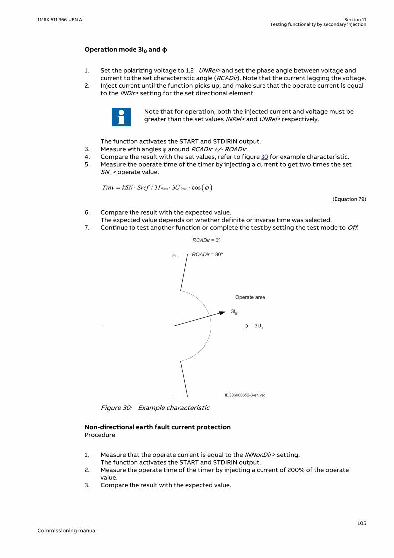
Operation mode 3I0 and φSEMOD175060-87 v8
1. Set the polarizing voltage to 1.2 · UNRel> and set the phase angle between voltage andcurrent to the set characteristic angle (RCADir). Note that the current lagging the voltage.
2. Inject current until the function picks up, and make sure that the operate current is equalto the INDir> setting for the set directional element.
Note that for operation, both the injected current and voltage must begreater than the set values INRel> and UNRel> respectively.
The function activates the START and STDIRIN output.3. Measure with angles j around RCADir +/- ROADir.4. Compare the result with the set values, refer to figure 30 for example characteristic.5. Measure the operate time of the timer by injecting a current to get two times the set
SN_> operate value.
( )0 0/ 3 3 costest testTinv kSN Sref I U j= × × ×
IECEQUATION2403 V1 EN-US (Equation 79)
6. Compare the result with the expected value.The expected value depends on whether definite or inverse time was selected.
7. Continue to test another function or complete the test by setting the test mode to Off.
-3U0
Operate area
3I0
RCADir = 0º
ROADir = 80º
IEC06000652-3-en.vsdIEC06000652 V3 EN-US
Figure 30: Example characteristic
Non-directional earth fault current protectionSEMOD175060-117 v10
Procedure
1. Measure that the operate current is equal to the INNonDir> setting.The function activates the START and STDIRIN output.
2. Measure the operate time of the timer by injecting a current of 200% of the operatevalue.
3. Compare the result with the expected value.
1MRK 511 366-UEN A Section 11Testing functionality by secondary injection
105Commissioning manual

The expected value depends on whether definite time tINNonDir or inverse time wasselected.
4. Continue to test another function or complete the test by setting the test mode to Off.
Residual overvoltage release and protectionSEMOD175060-131 v6
Procedure
1. Measure that the operate voltage is equal to the UN> setting.The function activates the START and STUN signals.
2. Measure the operate time by injecting a voltage 1.2 times set UN> operate value.3. Compare the result with the set tUN operate value.4. Inject a voltage 0.8 · UNRel> and a current high enough to operate the directional
function at the chosen angle.5. Increase the voltage until the directional function is released.6. Compare the measured value with the set UNRel> operate value.
11.4.4.2 Completing the testSEMOD175060-148 v4
Continue to test another function or end the test by changing the TestMode setting to Off.Restore connections and settings to their original values, if they were changed for testingpurposes.
11.4.5 Thermal overload protection, one time constant, Celsius/Fahrenheit LCPTTR/LFPTTR
M14950-2 v7
Prepare the IED for verification of settings as outlined in section "Requirements" andsection "Preparing for test" in this chapter.
Check that the input logical signal BLOCK is logical zero and that on the local HMI, the logicalsignal TRIP, START and ALARM are equal to logical zero.
11.4.5.1 Measuring the operate and time limit of set valuesM14950-8 v3
Testing the protection without external temperature compensation (NonComp)M14950-10 v10
1. Quickly set the measured current (fault current) in one phase to about 300% of IRef (tominimise the trip time), and switch the current off.
2. Reset the thermal memory on the local HMI under Main menu/Reset/Resettemperature/ThermalOverload1TimeConst(PTTR,26)/LFPTTR:x, Main menu/Reset/Reset temperature/ThermalOverload1TimeConst(PTTR,26)/LCPTTR:x,
3. Switch the fault current on and take note of the temperature, available on the local HMIunder Main menu/Test/Function status/Current protection/ThermOverLoad1TimeConst(PTTR,26)/LFPTTR:x/TEMP, Main menu/Test/Functionstatus/Current protection/ThermOverLoad1TimeConst(PTTR,26)/LCPTTR:x/TEMP,
4. Check the time until the actual temperature TEMP has reached the AlarmTemp levelduring injection.Monitor the signal ALARM until it appears on the corresponding binary output or on thelocal HMI.
5. Measure the LCPTTR/LFPTTRprotection trip time.Use the TRIP signal from the configured binary output to stop the timer.
6. Take the TEMP readings.Compare with the setting of TripTemp.
7. Activate the BLOCK binary input.The signals ALARM, START and TRIP should disappear.
8. Reset the BLOCK binary input.
Section 11 1MRK 511 366-UEN ATesting functionality by secondary injection
106Commissioning manual

9. Check the reset limit (TdReset).Monitor the signal START until it disappears on the corresponding binary output or onthe local HMI, take the TEMP readings and compare with the setting of ReclTemp.
10. Compare the measured trip time with the setting according to the formula.11. Reset the thermal memory.12. Continue to test another function or end the test by changing the test mode setting to
Off.
11.4.5.2 Completing the testM14950-48 v5
Continue to test another function or end the test by changing the TestMode setting to Off.Restore connections and settings to their original values, if they were changed for testingpurposes.
11.4.6 Directional underpower protection GUPPDUPSEMOD175027-3 v5
Prepare the IED for verification of settings as outlined in section "Requirements" andsection "Preparing for test" in this chapter.
11.4.6.1 Verifying the settingsSEMOD175027-7 v7
The underpower protection shall be set to values according to the real set values to be used.
The test is made by means of injection of voltage and current where the amplitude of bothcurrent and voltage and the phase angle between the voltage and current can be controlled.During the test, the analog outputs of active and reactive power shall be monitored.
1. Connect the test set for injection of voltage and current corresponding to the mode tobe used in the application. If a three-phase test set is available this could be used for allthe modes. If a single-phase current/voltage test set is available the test set should beconnected to a selected input for one-phase current and voltage.
Table 12: Calculation modes
Set value: Mode Formula used for complex power calculation
L1, L2, L3 * * *1 1 2 2 3 3L L L L L LS U I U I U I= × + × + ×
EQUATION1697 V1 EN-US (Equation 80)
Arone * *1 2 1 2 3 3L L L L L LS U I U I= × - ×
EQUATION1698 V1 EN-US (Equation 81)
PosSeq *3 PosSeq PosSeqS U I= × ×
EQUATION1699 V1 EN-US (Equation 82)
L1L2 * *1 2 1 2( )L L L LS U I I= × -
EQUATION1700 V1 EN-US (Equation 83)
L2L3 * *2 3 2 3( )L L L LS U I I= × -
EQUATION1701 V1 EN-US (Equation 84)
Table continues on next page
1MRK 511 366-UEN A Section 11Testing functionality by secondary injection
107Commissioning manual

Set value: Mode Formula used for complex power calculation
L3L1 * *3 1 3 1( )L L L LS U I I= × -
EQUATION1702 V1 EN-US (Equation 85)
L1 *1 13 L LS U I= × ×
EQUATION1703 V1 EN-US (Equation 86)
L2 *2 23 L LS U I= × ×
EQUATION1704 V1 EN-US (Equation 87)
L3 *3 33 L LS U I= × ×
EQUATION1705 V1 EN-US (Equation 88)
2. Adjust the injected current and voltage to the set values in % of IBase and UBase(converted to secondary current and voltage). The angle between the injected currentand voltage shall be set equal to the set direction Angle1, angle for stage 1 (equal to 0° forlow forward power protection and equal to 180° for reverse power protection). Checkthat the monitored active power is equal to 100% of rated power and that the reactivepower is equal to 0% of rated power.
3. Change the angle between the injected current and voltage to Angle1 + 90°. Check thatthe monitored active power is equal to 0% of rated power and that the reactive power isequal to 100% of rated power.
4. Change the angle between the injected current and voltage back to 0°. Decrease thecurrent slowly until the START1 signal, start of stage 1, is activated.
5. Increase the current to 100% of IBase.6. Switch the current off and measure the time for activation of TRIP1, trip of stage 1.7. If a second stage is used, repeat steps 2 to 6 for the second stage.
11.4.6.2 Completing the testSEMOD175027-15 v4
Continue to test another function or end the test by changing the TestMode setting to Off.Restore connections and settings to their original values, if they were changed for testingpurposes.
11.4.7 Directional overpower protection GOPPDOPSEMOD175058-3 v5
Prepare the IED for verification of settings as outlined in section "Requirements" andsection "Preparing for test" in this chapter.
11.4.7.1 Verifying the settingsSEMOD175058-7 v6
The overpower protection shall be set to values according to the real set values to be used. Thetest is made by means of injection of voltage and current where the amplitude of both currentand voltage and the phase angle between the voltage and current can be controlled. During thetest the analog outputs of active and reactive power shall be monitored.
1. Connect the test set for injection of voltage and current corresponding to the mode tobe used in the application. If a three phase test set is available this could be used for allthe modes. If a single phase current/voltage test set is available the test set should beconnected to a selected input for one phase current and voltage.
2. Adjust the injected current and voltage to the set rated values in % of IBase and UBase(converted to secondary current and voltage). The angle between the injected current
Section 11 1MRK 511 366-UEN ATesting functionality by secondary injection
108Commissioning manual

and voltage shall be set equal to the set direction Angle1, angle for stage 1 (equal to 0° forlow forward power protection and equal to 180° for reverse power protection). Checkthat the monitored active power is equal to 100% of rated power and that the reactivepower is equal to 0% of rated power.
3. Change the angle between the injected current and voltage to Angle1 + 90°. Check thatthe monitored active power is equal to 0% of rated power and that the reactive power isequal to 100% of rated power.
4. Change the angle between the injected current and voltage back to Angle1 value. Increasethe current slowly from 0 until the START1 signal, start of stage 1, is activated. Check theinjected power and compare it to the set value Power1, power setting for stage 1 in % ofSbase.
5. Increase the current to 100% of IBase and switch the current off.6. Switch the current on and measure the time for activation of TRIP1, trip of stage 1.7. If a second stage is used, repeat steps 2 to 6 for the second stage.
11.4.7.2 Completing the testSEMOD175058-66 v4
Continue to test another function or end the test by changing the TestMode setting to Off.Restore connections and settings to their original values, if they were changed for testingpurposes.
11.5 Voltage protectionSEMOD53540-1 v1
11.5.1 Two step undervoltage protection UV2PTUVM13796-2 v6
Prepare the IED for verification of settings as outlined in section "Requirements" andsection "Preparing for test" in this chapter.
11.5.1.1 Verifying the settingsM13796-9 v3
Verification of START value and time delay to operate for Step 1M13796-29 v9
1. Check that the IED settings are appropriate, especially the START value, the definite timedelay and the 1 out of 3 operation mode.
2. Supply the IED with three-phase voltages at their rated values.3. Slowly decrease the voltage in one of the phases, until the START signal appears.4. Note the operate value and compare it with the set value.
The operate value in secondary volts is calculated according to thefollowing equations:
For phase-to-earth measurement:
U UBase VT
VTprim
1
100 3
<× ×
sec
IECEQUATION2430 V1 EN-US (Equation 89)
For phase-to-phase measurement:
UUBase
VT
VTprim
1
100
<× ×
sec
IECEQUATION2431 V1 EN-US (Equation 90)5. Increase the measured voltage to rated load conditions.
1MRK 511 366-UEN A Section 11Testing functionality by secondary injection
109Commissioning manual

6. Check that the START signal resets.7. Instantaneously decrease the voltage in one phase to a value about 20% lower than the
measured operate value.8. Measure the time delay for the TRIP signal, and compare it with the set value.9. Check the inverse time delay by injecting a voltage corresponding to 0.8 × U1<.
For example, if the inverse time curve A is selected, the trip signals TR1and TRIP operate after a time corresponding to the equation:
t sk
U
U
( ) =
−
<
1
11
IECEQUATION2428 V1 EN-US (Equation 91)
where:
t(s) Operate time in seconds
k1 Settable time multiplier of the function for step 1
U Measured voltage
U1< Set start voltage for step 1
For example, if the measured voltage jumps from the rated value to 0.8 times the setstart voltage level and time multiplier k1 is set to 0.05 s (default value), then the TR1 andTRIP signals operate at a time equal to 0.250 s ± tolerance.
10. The test above can be repeated to check the inverse time characteristic at differentvoltage levels.
11. Repeat the above-described steps for Step 2 of the function.
Extended testingM13796-35 v8
The tests above can be repeated for 2 out of 3 and for 3 out of 3 operation mode.
11.5.1.2 Completing the testM13796-25 v5
Continue to test another function or end the test by changing the TestMode setting to Off.Restore connections and settings to their original values, if they were changed for testingpurposes.
11.5.2 Two step overvoltage protection OV2PTOVM13806-2 v6
Prepare the IED for verification of settings as outlined in section "Requirements" andsection "Preparing for test" in this chapter.
11.5.2.1 Verifying the settingsM13806-9 v2
Verification of single-phase voltage and time delay to operate for Step 1M13806-50 v8
1. Apply single-phase voltage below the set value U1>.2. Slowly increase the voltage until the ST1 signal appears.3. Note the operate value and compare it with the set value U1>.
Section 11 1MRK 511 366-UEN ATesting functionality by secondary injection
110Commissioning manual

The operate value in secondary volts is calculated according to thefollowing equations:
For phase-to-earth measurement:
U UBase VT
VTprim
1
100 3
>× ×
sec
IECEQUATION2426 V1 EN-US (Equation 92)
For phase-to-phase measurement:
UUBase
VT
VTprim
1
100
>× ×
sec
IECEQUATION2427 V1 EN-US (Equation 93)4. Decrease the voltage slowly and note the reset value.5. Set and apply about 20% higher voltage than the measured operate value for one phase.6. Measure the time delay for the TR1 signal and compare it with the set value.7. Check the inverse time delay by injecting a voltage corresponding to 1.2 × U1>.8. Repeat the test to check the inverse time characteristic at different over-voltage levels.9. Repeat the above-described steps for Step 2 of the function.
11.5.2.2 Extended testingGUID-BE4B4A36-CCEE-4020-B7DC-6A83A43D11F5 v2
1. The tests above can be repeated for 2 out of 3 and for 3 out of 3 operation mode.
11.5.2.3 Completing the testM13806-43 v6
Continue to test another function or end the test by changing the TestMode setting to Off.Restore connections and settings to their original values, if they were changed for testingpurposes.
11.6 Frequency protectionSEMOD53547-1 v1
11.6.1 Underfrequency protection SAPTUFM16289-2 v6
Prepare the IED for verification of settings as outlined in section "Requirements" andsection "Preparing for test" in this chapter.
11.6.1.1 Verifying the settingsM16289-15 v3
Verification of START value and time delay to operateM16289-17 v6
1. Check that the IED settings are appropriate, for example the START value and the timedelay.
2. Supply the IED with three-phase voltages at their rated values.3. Slowly decrease the frequency of the applied voltage, until the START signal appears.4. Note the operate value and compare it with the set value.5. Increase the frequency until rated operating levels are reached.
1MRK 511 366-UEN A Section 11Testing functionality by secondary injection
111Commissioning manual

6. Check that the START signal resets.7. Instantaneously decrease the frequency of the applied voltage to a value about 1% lower
than the operate value (a step change more than 2% will increase the time delay).8. Measure the time delay of the TRIP signal, and compare it with the set value. Note that
the measured time consists of the set value for time delay plus minimum operate time ofthe start function (80 - 90 ms).
Extended testingM16289-31 v5
1. The test above can be repeated to check the time to reset.2. The tests above can be repeated to test the frequency dependent inverse time
characteristic.
Verification of the low voltage magnitude blockingM16289-39 v7
1. Check that the IED settings are appropriate, for example the StartFrequency, UMin , andthe tDelay.
2. Supply the IED with three-phase voltages at rated values.3. Slowly decrease the magnitude of the applied voltage, until the BLKDMAGN signal
appears.4. Note the voltage magnitude value and compare it with the set value UMin.5. Slowly decrease the frequency of the applied voltage, to a value below StartFrequency.6. Check that the START signal does not appear.7. Wait for a time corresponding to tDelay, make sure that the TRIP signal does not appear.
11.6.1.2 Completing the testM16289-57 v5
Continue to test another function or end the test by changing the TestMode setting to Off.Restore connections and settings to their original values, if they were changed for testingpurposes.
11.6.2 Overfrequency protection SAPTOFM16290-2 v6
Prepare the IED for verification of settings as outlined in section "Requirements" andsection "Preparing for test" in this chapter.
11.6.2.1 Verifying the settingsM16290-12 v2
Verification of START value and time delay to operateM16290-14 v5
1. Check that the settings in the IED are appropriate, for example the START value and thetime delay.
2. Supply the IED with three-phase voltages at their rated values.3. Slowly increase the frequency of the applied voltage, until the START signal appears.4. Note the operate value and compare it with the set value.5. Decrease the frequency to rated operating conditions.6. Check that the START signal resets.7. Instantaneously increase the frequency of the applied voltage to a value about 1% lower
than the operate value (a step change more than 2% will increase the time delay).8. Measure the time delay for the TRIP signal, and compare it with the set value. Note that
the measured time consists of the set value for time delay plus minimum operate time ofthe start function (80 - 90 ms).
Extended testingM16290-28 v4
Section 11 1MRK 511 366-UEN ATesting functionality by secondary injection
112Commissioning manual

1. The test above can be repeated to check the time to reset.
Verification of the low voltage magnitude blockingM16290-34 v5
1. Check that the settings in the IED are appropriate, for example the StartFrequency, UMin,and the tDelay.
2. Supply the IED with three-phase voltages at their rated values.3. Slowly decrease the magnitude of the applied voltage, until the BLKDMAGN signal
appears.4. Note the voltage magnitude value and compare it with the set value, UMin.5. Slowly increase the frequency of the applied voltage, to a value above StartFrequency.6. Check that the START signal does not appear.7. Wait for a time corresponding to tDelay, make sure that the TRIP signal does not appear.
11.6.2.2 Completing the testM16290-52 v5
Continue to test another function or end the test by changing the TestMode setting to Off.Restore connections and settings to their original values, if they were changed for testingpurposes.
11.6.3 Rate-of-change frequency protection SAPFRCM16256-2 v6
Prepare the IED for verification of settings as outlined in section "Requirements" andsection "Preparing for test" in this chapter.
11.6.3.1 Verifying the settingsM16256-8 v1
Verification of START value and time delay to operateM16256-10 v5
1. Check that the settings in the IED are appropriate, especially the START value and thedefinite time delay. Set StartFreqGrad, to a rather small negative value.
2. Supply the IED with three-phase voltages at their rated values.3. Slowly decrease the frequency of the applied voltage, with an increasing rate-of-change
that finally exceeds the setting of StartFreqGrad, and check that the START signalappears.
4. Note the operate value and compare it with the set value.5. Increase the frequency to rated operating conditions, and zero rate-of-change.6. Check that the START signal resets.7. Instantaneously decrease the frequency of the applied voltage to a value about 20%
lower than the nominal value.8. Measure the time delay for the TRIP signal, and compare it with the set value.
Extended testingM16256-29 v4
1. The test above can be repeated to check a positive setting of StartFreqGrad.2. The tests above can be repeated to check the time to reset.3. The tests above can be repeated to test the RESTORE signal, when the frequency
recovers from a low value.
1MRK 511 366-UEN A Section 11Testing functionality by secondary injection
113Commissioning manual
11.6.3.2 Completing the testM16256-39 v4
Continue to test another function or end the test by changing the TestMode setting to Off.Restore connections and settings to their original values, if they were changed for testingpurposes.
11.6.4 Frequency time accumulation protection function FTAQFVRGUID-F7BD8E10-EF88-4698-87F4-0D4365004705 v2
Prepare the IED for verification of settings as outlined in section “Overview” and section“Preparing for test” in this chapter.
11.6.4.1 Verifying the settingsGUID-864636E0-6399-44E1-BD2C-C2113FB78C61 v3
Time measurement and the injection of current and voltage can be done using a common testequipment.
Verification of the START value and time delay to operation
1. Connect the test set for the injection of three-phase currents and three-phase voltages tothe appropriate current and voltage terminals of the IED.
2. Ensure that the settings in the IED are appropriate, especially the CurrStartLevel,FreqHighLimit, FreqLowLimit, UHighLimit and ULowLimit setting.
3. Supply the IED with three-phase currents and voltages at their rated value.4. Slowly decrease the frequency of the applied voltage until it crosses the frequency high
limit and the START signal appears.5. Check that the FREQOK signal appears.6. Compare the operate value to the set frequency high limit value.7. Decrease the frequency of the applied voltage until it crosses the frequency low limit and
the START signal disappears.8. Check that the FREQOK signal disappears.9. Compare the reset value to the set frequency low limit value.10. Readjust the frequency of the applied voltage (with steps of 0.001 Hz/s) to a value within
the set frequency band limit.11. Ensure that the START signal reappears.12. Wait for a time corresponding to tCont and ensure that the TRIP and TRIPCONT signals
are generated.13. Measure the time delay for the TRIP signal and compare it to the set value.
Verification of the ACCALARM value and time delay to operation
1. Connect the test set for the injection of three-phase currents and three-phase voltages tothe appropriate current and voltage terminals of the IED.
2. Ensure that the settings in the IED are appropriate for the default settings, especially theCurrStartLevel, FreqHighLimit, FreqLowLimit, UHighLimit and ULowLimit setting.
3. Supply the IED with three-phase currents and voltages at their rated value.4. Slowly decrease the frequency of the applied voltage until it crosses the frequency high
limit and the START signal appears.5. Continuously change the frequency of the applied voltage, so that for a certain time the
frequency is outside the set band limit and falls gradually within the band limit.6. Count only the time when the frequency lies within the set frequency band limit. Wait for a
time corresponding to tAccLimit and ensure that the ACCALARM signal appears.7. Measure the time delay for the ACCALARM signal and compare it to the set value.
Section 11 1MRK 511 366-UEN ATesting functionality by secondary injection
114Commissioning manual

Extended testing
1. To check the value of TRIPACC, repeat the above test case in such a way that thefrequency of the applied voltage is within the set frequency band when time approachesthe tAccLimit setting value.
Verification of generator start and stop logic
1. Ensure that the settings in the IED are appropriate to the default settings, especially theCurrStartLevel, FreqHighLimit, FreqLowLimit, UHighLimit and ULowLimit.
2. Ensure that the setting CBCheck is enabled.3. Supply the IED with three-phase currents and voltages at their rated values.4. Slowly decrease the frequency of the applied voltage until the START signal appears.5. Activate the CBOPEN input signal.6. Slowly decrease the injected current below the CurrStartLevel value until the START signal
disappears.7. Compare the current magnitude value to the set value.
Verification of voltage band limit check logic
1. Ensure that the settings in the IED are appropriate to the default settings, especially theCurrStartLevel, FreqHighLimit, FreqLowLimit, UHighLimit and ULowLimit settings.
2. Ensure that the EnaVoltCheck is enabled.3. Supply the IED with three-phase currents and voltages at their rated values.4. Check that the VOLTOK signal appears.5. Slowly decrease the frequency of the applied voltage until the START signal appears.6. Slowly decrease the positive-sequence voltage of the injected voltage below the
ULowLimit value until the START signal disappears.7. Check that the VOLTOK signal disappears.8. Compare the reset value to the set voltage low limit value.9. Readjust the positive-sequence voltage of the applied voltage to a value within the set
voltage band limits.10. Check that the START signal reappears.11. Slowly increase the positive-sequence voltage of the injected voltage above the
UHighLimit value until the START signal disappears.12. Compare the reset value to the set voltage high limit value.
11.6.4.2 Completing the testGUID-83C3F041-9553-4804-9A39-B3E46A5C9AE6 v2
• Continue to test another function or end the test by changing the Test mode setting tooff.
• Restore connections and settings to their original values if they were changed for testingpurposes.
11.7 Multipurpose protectionSEMOD53552-1 v1
11.7.1 General current and voltage protection CVGAPCSEMOD56488-3 v3
Prepare the IED for verification of settings as outlined in section "Requirements" andsection "Preparing for test" in this chapter.
One of the new facilities within the general current and voltage protection function CVGAPC isthat the value, which is processed and used for evaluation in the function, can be chosen inmany different ways by the setting parameters CurrentInput and VoltageInput.
1MRK 511 366-UEN A Section 11Testing functionality by secondary injection
115Commissioning manual

These setting parameters decide what kind of preprocessing the connected three-phase CTand VT inputs shall be subjected to. That is, for example, single-phase quantities, phase-to-phase quantities, positive sequence quantities, negative sequence quantities, maximumquantity from the three-phase group, minimum quantity from the three-phase group,difference between maximum and minimum quantities (unbalance) can be derived and thenused in the function.
Due to the versatile possibilities of CVGAPC itself, but also the possibilities of logiccombinations in the application configuration of outputs from more than one CVGAPCfunction block, it is hardly possible to define a fully covering general commissioning test.
11.7.1.1 Built-in overcurrent feature (non-directional)SEMOD56488-9 v5
Procedure
1. Go to Main menu/Test/Function test modes/Multipurpose protection/GeneralCurrentVoltage(GAPC)/CVGAPC:x and make sure that CVGAPC to be tested isunblocked and other functions that might disturb the evaluation of the test are blocked.
2. Connect the test set for injection of three-phase currents to the appropriate currentterminals of the IED.
3. Inject current(s) in a way that relevant measured current (according to setting parameterCurrentInput) is created from the test set. Increase the current(s) until the low set stageoperates and check against the set operate value.
4. Decrease the current slowly and check the reset value.5. Block high set stage if the injection current will activate the high set stage when testing
the low set stage according to below.6. Connect a TRIP output contact to the timer.7. Set the current to 200% of the operate value of low set stage, switch on the current and
check the time delay.For inverse time curves, check the operate time at a current equal to 110% of the operatecurrent at tMin.
8. Check that TRIP and START contacts operate according to the configuration logic.9. Release the blocking of the high set stage and check the operate and reset value and the
time delay for the high set stage in the same way as for the low set stage.10. Finally check that START and TRIP information is stored in the event menu.
Information on how to use the event menu is found in the operator'smanual.
11.7.1.2 Overcurrent feature with current restraintSEMOD56488-35 v3
The current restraining value has also to be measured or calculated and the influence on theoperation has to be calculated when the testing of the operate value is done.
Procedure
1. Operate value measurementThe current restraining value has also to be measured or calculated and the influence onthe operation has to be calculated when the testing of the operate value is done.
11.7.1.3 Overcurrent feature with voltage restraintSEMOD56488-44 v5
Procedure
Section 11 1MRK 511 366-UEN ATesting functionality by secondary injection
116Commissioning manual

1. Connect the test set for injection of three-phase currents and three-phase voltages tothe appropriate current and voltage terminals of the IED.
2. Inject current(s) and voltage(s) in a way that relevant measured (according to settingparameter CurrentInput and VoltageInput) currents and voltages are created from thetest set.Overall check in principal as above (non-directional overcurrent feature)
3. Operate value measurementThe relevant voltage restraining value (according to setting parameter VoltageInput) hasalso to be injected from the test set and the influence on the operate value has to becalculated when testing of the operate value is done.
4. Operate time measurementDefinite times may be tested as above (non-directional overcurrent feature). For inversetime characteristics the START value (to which the overcurrent ratio has to be calculated)is the actual pickup value as got with actual restraining from the voltage restrainingquantity.
11.7.1.4 Overcurrent feature with directionalitySEMOD56488-60 v5
Please note that the directional characteristic can be set in two different ways either justdependent on the angle between current and polarizing voltage (setting parameterDirPrinc_OC1 or DirPrinc_OC2 set to or in a way that the operate value also is dependent on theangle between current and polarizing voltage according to the I · cos(F) law (settingparameter DirPrinc_OC1 or DirPrinc_OC2 set to I · cos(F). This has to be known if a moredetailed measurement of the directional characteristic is made, than the one described below.
Procedure
1. Connect the test set for injection of three-phase currents and three-phase voltages tothe appropriate current and voltage terminals of the IED.
2. Inject current(s) and voltage(s) in a way that relevant measured (according to settingparameter CurrentInput and VoltageInput) currents and voltages are created from thetest set.
3. Set the relevant measuring quantity current to lag or lead (lag for negative RCA angle andlead for positive RCA angle) the relevant polarizing quantity voltage by an angle equal tothe set IED characteristic angle (rca-dir) when forward directional feature is selected andthe CTstarpoint configuration parameter is set to ToObject.If reverse directional feature is selected or CTstarpoint configuration parameter is set toFromObject, the angle between current and polarizing voltage shall be set equal to rca-dir+180°.
4. Overall check in principal as above (non-directional overcurrent feature)5. Reverse the direction of the injection current and check that the protection does not
operate.6. Check with low polarization voltage that the feature becomes non-directional, blocked or
with memory according to the setting.
11.7.1.5 Over/Undervoltage featureSEMOD56488-83 v2
Procedure
1. Connect the test set for injection three-phase voltages to the appropriate voltageterminals of the IED.
2. Inject voltage(s) in a way that relevant measured (according to setting parameterVoltageInput) voltages are created from the test set.
3. Overall check in principal as above (non-directional overcurrent feature) andcorrespondingly for the undervoltage feature.
1MRK 511 366-UEN A Section 11Testing functionality by secondary injection
117Commissioning manual

11.7.1.6 Completing the testSEMOD56488-99 v2
Continue to test another function or end the test by changing the TestMode setting to Off.Restore connections and settings to their original values, if they were changed for testingpurposes.
11.8 Secondary system supervisionSEMOD53556-1 v1
11.8.1 Current circuit supervision CCSSPVCM12917-25 v7
Prepare the IED for verification of settings as outlined in section "Requirements" andsection "Preparing for test" in this chapter.
The Current circuit supervision function CCSSPVC is conveniently tested with the same three-phase test set as used when testing the measuring functions in the IED.
The condition for this procedure is that the setting of IMinOp is lower than the setting ofIp>Block.
11.8.1.1 Verifying the settingsM12917-31 v7
1. Check the input circuits and the operate value of the IMinOp current level detector byinjecting current, one phase at a time.
2. Check the phase current blocking function for all three phases by injecting current, onephase at a time. The output signals shall reset with a delay of 1 second when the currentexceeds 1.5 · IBase.
3. Inject a current 0.1 · IBase to the reference current input I5.4. Increase slowly the current in one of the phases current input and check that FAIL output
is obtained when the current is about 0.9 · IBase.
11.8.1.2 Completing the testM12917-43 v4
Continue to test another function or end the test by changing the TestMode setting to Off.Restore connections and settings to their original values, if they were changed for testingpurposes.
11.8.2 Fuse failure supervision FUFSPVCM1405-2 v8
Prepare the IED for verification of settings as outlined in section "Requirements" andsection "Preparing for test" in this chapter.
The verification is divided in two main parts. The first part is common to all fuse failuresupervision options, and checks that binary inputs and outputs operate as expected accordingto actual configuration. In the second part the relevant set operate values are measured.
11.8.2.1 Checking that the binary inputs and outputs operate as expectedM1405-9 v8
1. Simulate normal operating conditions with the three-phase currents in phase with theircorresponding phase voltages and with all of them equal to their rated values.
2. Connect the nominal dc voltage to the DISCPOS binary input.
Section 11 1MRK 511 366-UEN ATesting functionality by secondary injection
118Commissioning manual
• The signal BLKU should appear with almost no time delay.• The signals BLKZ and 3PH should not appear on the IED.• Only the distance protection function can operate.• Undervoltage-dependent functions must not operate.
3. Disconnect the dc voltage from the DISCPOS binary input terminal.4. Connect the nominal dc voltage to the MCBOP binary input.
• The BLKUand BLKZ signals should appear without any time delay.• All undervoltage-dependent functions must be blocked.
5. Disconnect the dc voltage from the MCBOP binary input terminal.6. Disconnect one of the phase voltages and observe the logical output signals on the
binary outputs of the IED.BLKU and BLKZ signals should appear simultaneously wether the BLKU and BLKZ resetdepends on the setting SealIn “on” or “off”. If “on” no reset, if “off” reset.
7. After more than 5 seconds disconnect the remaining two-phase voltages and all threecurrents.
• There should be no change in the high status of the output signals BLKU and BLKZ.• The signal 3PH will appear.
8. Establish normal voltage and current operating conditions simultaneously and observethe corresponding output signals.They should change to logical 0 as follows:
• Signal 3PH after about 25ms• Signal BLKU after about 50ms• Signal BLKZ after about 200ms
11.8.2.2 Measuring the operate value for the negative sequence functionM1405-46 v11
Measure the operate value for the negative sequence function, if included in the IED.
1. Simulate normal operating conditions with the three-phase currents in phase with theircorresponding phase voltages and with all of them equal to their rated values.
2. Slowly decrease the measured voltage in one phase until the BLKU signal appears.3. Record the measured voltage and calculate the corresponding negative-sequence voltage
according to the equation (observe that the voltages in the equation are phasors):
3 2 12⋅ + ⋅ + ⋅U U U UL L2 L3= a a
EQUATION707 V2 EN-US (Equation 94)
Where:
UL1 , UL2 and UL3IEC00000275 V1 EN-US
are the measured phase voltages
2
33
1 0, 52
j
a e jp×
= × = - +.IECEQUATION00022 V2 EN-US
4. Compare the result with the set value of the negative-sequence operating voltage(consider that the set value 3U2> is in percentage of the base voltage UBase).
5. Repeat steps 1 and 2. Then slowly increase the measured current in one phase until theBLKU signal disappears.
6. Record the measured current and calculate the corresponding negative-sequence currentaccording to the equation (observe that the currents in the equation are phasors):
1MRK 511 366-UEN A Section 11Testing functionality by secondary injection
119Commissioning manual
2
1 2 323 L L LI I a I a I× = + × + ×
IECEQUATION00021 V1 EN-US (Equation 97)
Where:
1 2 3L L LI I and I , IECEQUATION00020 V1 EN-US
are the measured phase currents
2
33
1 0, 52
j
a e jp×
= × = - +.IECEQUATION00022 V2 EN-US
7. Compare the result with the set value of the negative-sequence operating current.Consider that the set value 3I2< is in percentage of the base current IBase.
11.8.2.3 Measuring the operate value for the zero-sequence functionM1405-72 v10
Measure the operate value for the zero-sequence function, if included in the IED.
1. Simulate normal operating conditions with the three-phase currents in phase with theircorresponding phase voltages and with all of them equal to their rated values.
2. Slowly decrease the measured voltage in one phase until the BLKU signal appears.3. Record the measured voltage and calculate the corresponding zero-sequence voltage
according to the equation (observe that the voltages in the equation are phasors):
3 U0× UL1 UL2 UL3+ +=
IEC00000276 V1 EN-US (Equation 100)
Where:
UL1 , UL2 and UL3IEC00000275 V1 EN-US
are the measured phase voltages
4. Compare the result with the set value of the zero-sequence operating voltage (considerthat the set value 3U0> is in percentage of the base voltage.)
5. Repeat steps 1 and 2. Then slowly increase the measured current in one phase until theBLKU signal disappears.
6. Record the measured current and calculate the corresponding zero-sequence currentaccording to the equation (observe that the currents in the equation are phasors):
0 L1 L2 L33 =I I I I× + +IECEQUATION00019 V1 EN-US (Equation 102)
Where:
1 2 3L L LI I and I , IECEQUATION00020 V1 EN-US
are the measured phase currents
7. Compare the result with the set value of the zero-sequence operate current. Considerthat the set value 3I0< is in percentage of the base current IBase.
11.8.2.4 Measuring the operate value for the dead line detection functionGUID-4ABF1FD4-F6D3-4109-AFE5-552875E558A0 v4
Section 11 1MRK 511 366-UEN ATesting functionality by secondary injection
120Commissioning manual

1. Apply three-phase voltages with their rated value and zero currents.2. Decrease the measured voltage in one phase until the DLD1PH signal appears.3. This is the point at which the dead line condition is detected. Check the value of the
decreased voltage with the set value UDLD< (UDLD< is in percentage of the base voltageUBase).
4. Apply three-phase currents with their rated value and zero voltages.5. Decrease the measured current in one phase until the DLD1PH signal appears.6. This is the point at which the dead line condition is detected. Check the value of the
decreased current with the set value IDLD< (IDLD< is in percentage of the base currentIBase).
11.8.2.5 Checking the operation of the du/dt and di/dt based functionM1405-96 v11
Check the operation of the du/dt and di/dt based function if included in the IED.
1. Simulate normal operating conditions with the three-phase currents in phase with theircorresponding phase voltages and with all of them equal to their rated values.
2. Change the voltages and currents in all three phases simultaneously.The voltage change must be higher than the set value DU> and the current change mustbe lower than the set value DI<.
• The BLKU and BLKZ signals appear without any time delay. The BLKZ signal will beactivated only if the internal deadline detection is not activated at the same time.
• 3PH should appear after 5 seconds, if the remaining voltage levels are lower thanthe set UDLD< of the dead line detection function.
3. Apply normal conditions as in step 1.The BLKU, BLKZ and 3PH signals should reset, if activated, see step 1 and 2.
4. Change the voltages and currents in all three phases simultaneously.The voltage change must be higher than the set value DU> and the current change mustbe higher than the set value DI<.The BLKU, BLKZ and 3PH signals should not appear.
5. Repeat step 2.6. Connect the nominal voltages in all three phases and feed a current below the operate
level in all three phases.7. Keep the current constant. Disconnect the voltage in all three phases simultaneously.
The BLKU, BLKZ and 3PH signals should not appear.8. Change the magnitude of the voltage and current for phase 1 to a value higher than the
set value DU> and DI<.9. Check that the start output signals STDUL1 and STDIL1 and the general start signals
STDU or STDI are activated.10. Check that the start output signals for the current and voltage phases 2 and 3 are
activated by changing the magnitude of the voltage and current for phases 2 and 3.
11.8.2.6 Completing the testM1405-130 v5
Continue to test another function or end the test by changing the TestMode setting to Off.Restore connections and settings to their original values, if they were changed for testingpurposes.
1MRK 511 366-UEN A Section 11Testing functionality by secondary injection
121Commissioning manual

11.9 ControlSEMOD53560-1 v1
11.9.1 Single command, 16 signals SINGLECMDSEMOD172444-5 v3
For the single command function block, it is necessary to configure the output signal tocorresponding binary output of the IED. The operation of the single command function(SINGLECMD) is then checked from the local HMI by applying the commands with Mode = Off,Steady or Pulse, and by observing the logic statuses of the corresponding binary output.Command control functions included in the operation of different built-in functions must betested at the same time as their corresponding functions.
11.10 LogicSEMOD53577-1 v1
11.10.1 Tripping logic, common 3-phase output SMPPTRCSEMOD54375-102 v8
Prepare the IED for verification of settings as outlined in section "Requirements" andsection "Preparing for test" in this chapter.
This function is functionality tested together with other protection functions (line differentialprotection,earth-fault overcurrent protection, and so on) within the IED. It is recommendedthat the function is tested together with the autorecloser function, when built into the IED orwhen a separate external unit is used for reclosing purposes. The instances of SMPPTRC areidentical except for the name of the function block SMPPTRC. The testing is preferably done inconjunction with the protection system and autoreclosing function.
11.10.1.1 Three-phase operating modeSEMOD54375-106 v8
1. Check that AutoLock and TripLockout are both set to Off.2. Initiate a three-phase fault.
An adequate time interval between the faults should be considered, to overcome areclaim time caused by the possible activation of the Autorecloser function SMBRREC.The function must issue a three-phase trip in all cases, when trip is initiated by anyprotection or some other built-in or external function. The following functional outputsignals must always appear simultaneously: TRIP, TRL1, TRL2, TRL3 and TR3P.
11.10.1.2 1ph/3ph operating modeSEMOD54375-116 v4
In addition to various other tests, the following tests should be performed. They depend onthe complete configuration of an IED:
Procedure
1. Make sure that TripLockout and AutoLock are both set to Off.2. Initiate different single-phase-to-earth faults one at a time.
Single-phase tripping will only be allowed when an autoreclose attempt will follow. Theautorecloser function SMBRREC has the functionality such as the long trip time, CB readyand so on, which can prevent a proper single-phase tripping and autoreclose. To by-passthis problem the fault initiation should be with a test set and with the autoreclose in fullservice with a test set connected to the distance protection function. Consider using anadequate time interval between faults, to overcome a reclaim time of which is activatedby SMBRREC. Only a single-phase trip should occur for each separate fault and only one
Section 11 1MRK 511 366-UEN ATesting functionality by secondary injection
122Commissioning manual

of the trip outputs (TRLn) should be activated at a time. Functional outputs TRIP andTR1P should be active during each fault. No other outputs should be active.
3. Initiate different phase-to-phase and three-phase faults.Consider using an adequate time interval between faults, to overcome a reclaim time,which is activated by SMBRREC. A three-phase trip should occur for each separate faultand all of the trips. Functional outputs TRIP, all TRLn and TR3P should be active at eachfault.
No other outputs should be active.
4. Initiate a single phase-to-earth fault and switch it off immediately when the trip signal isissued for the corresponding phase. Initiate the same fault once again within the reclaimtime of the used SMBRREC.A single-phase fault shall be given at the first fault. A three-phase trip must be initiatedfor the second fault. Check that the corresponding trip signals appear after both faults.Functional outputs TRIP, TRLn and TR1P should be active during first fault. No otheroutputs should be active. Functional outputs TRIP, all TRLn and TR3P should be activeduring second fault.
5. Initiate a single phase-to-earth fault and switch it off immediately when the trip signal isissued for the corresponding phase. Initiate the second single phase-to-earth fault in oneof the remaining phases within the time interval, shorter than tEvolvingFault (defaultsetting 2.0s) and shorter than the dead-time of SMBRREC, when included in theprotection scheme.Check that the second trip is a three-phase trip and that a three-phase autoreclosingattempt is given after the three-phase dead time. Functional outputs TRIP, TRLn andTR1P should be active during the first fault. No other outputs should be active. Functionaloutputs TRIP, all TRLn and TR3P should be active during second fault.
11.10.1.3 1ph/2ph/3ph operating modeSEMOD54375-143 v4
In addition to other tests, the following tests, which depend on the complete configuration ofan IED, should be carried out.
Procedure
1. Make sure that AutoLock and TripLockout are both set to Off.2. Initiate different single-phase-to-earth faults one at a time.
Take an adequate time interval between faults into consideration, to overcome a reclaimtime, which is activated by the autorecloser function SMBRREC. Only a single-phase tripshould occur for each separate fault and only one of the trip outputs (TRLn) should beactivated at a time. Functional outputs TRIP and TR1P should be active at each fault. Noother outputs should be active.
3. Initiate different phase-to-phase faults one at a time.Take an adequate time interval between faults into consideration, to overcome a reclaimtime which is activated by SMBRREC. Only a two-phase trip should occur for eachseparate fault and only corresponding two trip outputs (TRLn) should be activated at atime. Functional outputs TRIP and TR2P should be active at each fault. No other outputsshould be active.
4. Initiate a three-phase fault.Take an adequate time interval between faults into consideration, to overcome a reclaimtime, which may be activated by SMBRREC. Only a three-phase trip should occur for thefault and all trip outputs (TRLn) should be activated at the same time. Functional outputsTRIP and TR3P should be active at each fault. No other outputs should be active.
5. Initiate a single phase-to-earth fault and switch it off immediately when the trip signal isissued for the corresponding phase. Initiate the same fault once again within the reclaimtime of the used SMBRREC.
1MRK 511 366-UEN A Section 11Testing functionality by secondary injection
123Commissioning manual

A single-phase fault shall be given at the first fault. A three-phase trip must be initiatedfor the second fault. Check that the corresponding trip signals appear after both faults.Functional outputs TRIP, TRLn and TR1P should be active during first fault. No otheroutputs should be active. Functional outputs TRIP, all TRLn and TR3P should be activeduring second fault.
6. Initiate a single phase-to-earth fault and switch it off immediately when the trip signal isgenerated for the corresponding phase. Initiate the second single-phase-to-earth fault inone of the remaining phases within the time interval, shorter than tEvolvingFault (defaultsetting 2.0s) and shorter than the dead-time of SMBRREC, when included in theprotection scheme.Check that the second trip is a three-phase trip and that a three-phase autoreclosingattempt is given after the three-phase dead time. Functional outputs TRIP, TRLn andTR1P should be active during first fault. No other outputs should be active. Functionaloutputs TRIP, all TRLn and TR3P should be active during second fault.
7. Initiate a phase-to-phase fault and switch it off immediately when the trip signal isissued for the corresponding two phases. Initiate a second phase-to-phase fault betweentwo other phases within the time interval, shorter thantEvolvingFault (default setting2.0s).Check, that the output signals, issued for the first fault, correspond to a two- trip forincluded phases. The output signals generated by the second fault must correspond tothe three-phase tripping action.
11.10.1.4 Circuit breaker lockoutSEMOD54375-170 v10
The following tests should be carried out when the built-in lockout function is used in additionto possible other tests, which depends on the complete configuration of an IED.
1. Check that AutoLock and TripLockout are both set to Off.2. Activate shortly the set lockout (SETLKOUT) signal in the IED.3. Check that the circuit breaker lockout (CLLKOUT) signal is set.4. Activate shortly thereafter, the reset lockout (RSTLKOUT) signal in the IED.5. Check that the circuit breaker lockout (CLLKOUT) signal is reset.6. Initiate a three-phase fault.
A three-phase trip should occur and all trip outputs TRL1, TRL2, TRL3 should be activated.Functional outputs TRIP and TR3P should be active at each fault. The output CLLKOUTshould not be set.
7. Activate the automatic lockout function, set AutoLock = On and repeat.Besides the TRIP outputs, CLLKOUT should be set.
8. Reset the lockout signal by activating the reset lockout (RSTLKOUT) signal.9. Activate the trip signal lockout function, set TripLockout = On and repeat.
All trip outputs (TRL1, TRL2, TRL3) and functional outputs TRIP and TR3P must be activeand stay active after each fault, CLLKOUT should be set.
10. Reset the lockout.All functional outputs should reset.
11. Deactivate the TRIP signal lockout function, set TripLockout = Off and the automaticlockout function, set AutoLock = Off.
11.10.1.5 Completing the testSEMOD54375-203 v6
Continue to test another function or end the test by changing the TestMode setting to Off.Restore connections and settings to their original values, if they were changed for testingpurposes.
Section 11 1MRK 511 366-UEN ATesting functionality by secondary injection
124Commissioning manual

11.11 MonitoringSEMOD53581-1 v1
11.11.1 Gas medium supervision SSIMGGUID-0A83B4D5-51FF-43CB-8DC7-AFCEA2BC7B69 v1
Prepare the IED for verification of settings as outlined in section "Testing the liquid mediumsupervision for alarm and lock out conditions" and section "Completing the test" in thischapter.
Check that the input logical signal BLOCK is logical zero and that on the local HMI, the logicalsignals PRES_ALM, PRES_LO, TEMP_ALM and TEMP_LO are equal to logical zero.
11.11.1.1 Testing the liquid medium supervision for alarm and lock out conditionsGUID-768DAAC8-F89D-4401-B86D-9B26FD7224F6 v1
1. Connect binary inputs to consider gas pressure and gas density to initiate the alarms.2. Consider the analogue pressure input PRESSURE to initiate the alarms.3. Gas pressure lock out input can be used to set PRES_LO signal, check the signal status in
local HMI under Main menu/Test/Function status/Monitoring/Gas medium supervisionSSIMG/PRES_LO
4. Reduce the pressure level input below PresAlmLimit, check for PRES_ALM signal status inlocal HMI under Main menu/Test/Function status/Monitoring/Gas medium supervisionSSIMG/PRES_ALM
5. Activate BLOCK binary input, the signals PRES_ALM, PRES_LO should disappear.6. Reset the BLOCK binary input.7. Check for reset lock out input RESET_LO to reset PRES_LO lock out signal.8. Conduct these steps for temperature input as well to detect and reset TEMP_ALM and
TEMP_LO signals.9. Continue to test another function or end the test by changing the TestMode setting to
off.
11.11.1.2 Completing the testGUID-DD08C598-A35C-4300-9555-A0877F7DC511 v1
Continue to test another function or end the test by changing the TestMode setting to Off.Restore connections and settings to their original values, if they were changed for testingpurposes.
11.11.2 Liquid medium supervision SSIMLGUID-6426FDDA-B949-4FE7-BF42-B52014A9344B v1
Prepare the IED for verification of settings as outlined in section "Liquid medium supervisionSSIML" and section "Completing the test" in this chapter.
Check that the input logical signal BLOCK is logical zero and that on the local HMI, the logicalsignals LVL_ALM, LVL_LO, TEMP_ALM and TEMP_LO are equal to logical zero.
11.11.2.1 Testing the liquid medium supervision for alarm and lock out conditionsGUID-C1F1E6CA-9512-4358-A4E7-84CC3698D156 v1
1. Connect the binary inputs to consider liquid level to initiate the alarms.2. Consider the analogue level input LEVEL to initiate the alarms.3. Liquid level lock out input can be used to set LVL_LO signal, check the signal status in
local HMI under Main menu/Test/Function status/Monitoring/Liquid mediumsupervision SSIML/LVL_LO
4. Reduce the liquid level input below LevelAlmLimit, check for LVL_ALM signal status inlocal HMI under Main menu/Test/Function status/Monitoring/Liquid mediumsupervision SSIML/LVL_ALM
1MRK 511 366-UEN A Section 11Testing functionality by secondary injection
125Commissioning manual

5. Activate BLOCK binary input, the signals LVL_ALM, LVL_LO should disappear.6. Reset the BLOCK binary input.7. Check for reset lock out input RESET_LO to reset the LVL_LO lock out signal.8. Conduct these steps for temperature input as well to detect and reset TEMP_ALM and
TEMP_LO signals.9. Continue to test another function or end the test by changing the TestMode setting to
Off.
11.11.2.2 Completing the testGUID-1A0D8AF0-4C48-45E8-B31D-96734ED1A4D2 v1
Continue to test another function or end the test by changing the TestMode setting to Off.Restore connections and settings to their original values, if they were changed for testingpurposes.
11.11.3 Breaker monitoring SSCBRGUID-10D26C82-79FF-4EAD-AE4A-2F2DBE965087 v2
Prepare the IED for verification of settings outlined in section “Testing the IED operation”.
The Signal Monitoring tool in PCM600 shows the service values that are available on the LocalHMI as well.
Values of the logical signals belong to the breaker monitoring are available on the local HMIunder: Main menu/Test/Function status/Monitoring/BreakerMonitoring/SSCBR:x
11.11.3.1 Verifying the settingsGUID-962A344D-5F8D-49A6-B3AC-29C7FEED0A3D v4
1. Connect the test set for the injection of a three-phase current to the appropriate currentterminals of the IED.
2. If current need to be injected for a particular test, it should be done in the phase selectedby the PhSel parameter.
3. Follow the sequence for positioning the auxiliary contacts before testing:
POSCLOSE 0 1 0
POSOPEN 0 0 1
4. Test of CB contact travel time
4.1. Test the set timing defined by OpenTimeCorr, CloseTimeCorr, tTrOpenAlm andtTrCloseAlm.
4.2. Change the status of the auxiliary contacts such that travel time to open TTRVOPand travel time to close TTRVCL exceed the respective set values (tTrOpenAlm andtTrCloseAlm). The measured travel time for opening and closing is shown on TTRVOPand TTRVCL respectively.
4.3. Check that TRVTOPAL and TRVTCLAL are activated.
5. Test of CB status
5.1. Test the set current level defined by AccStopCurr.5.2. Check the CLOSEPOS output by changing the POSOPEN to 0 and POSCLOSE to 1.5.3. Check the OPENPOS output by changing the POSOPEN to 1 and POSCLOSE to 0 and
also inject the current in the selected phase slightly lower and higher thanAccStopCurr set value. Only for a current lower than set AccStopCurr should activatethe output POSOPEN.
5.4. Check the circuit breaker is in INVDPOS if auxiliary contacts read same value or CB isopen and inject the current in selected phase more than AccStopCurr set value.
6. Test of remaining life of CB
Section 11 1MRK 511 366-UEN ATesting functionality by secondary injection
126Commissioning manual

6.1. Test the set timing defined byRatedOperCurr, RatedFltCurr, OperNoRated,OperNoFault, DirCoef, CBLifeAlmLevel.
6.2. Vary the phase current in the selected phase from below rated operated current,RatedOperCurr to above rated fault current, RatedFltCurr of a breaker.
6.3. The remaining life of CB output CBLIFEPH is estimated when the CB is changed fromclosed to open position. Check that the output CBLIFEPH is decreased with a valuethat corresponds to the injected current.
6.4. CBLIFEAL is activated as soon as CBLIFEPH is below the set CBLifeAlmLevel value.
7. Test of accumulated energy
7.1. Test the actual set values defined by AccSelCal to Aux Contact, ContTrCorr andAlmAccCurrPwr.
7.2. Inject phase current in the selected phase such that its value is greater than setAccStopCurr value.
7.3. When the breaker goes to open position, accumulated energy IPOWPH is calculated.The calculated value can be seen on the output IPOWPH.
7.4. Alarm signal IPOWALPH appears when IPOWPH is greater than set AlmAccCurrPwrvalue.
7.5. Lockout signal IPOWLOPH appears if IPOWPH exceeds further to the threshold valueLOAccCurrPwr.
7.6. Calculation of accumulated energy IPOWPH is stopped when injected current is lowerthan set AccStopCurr value.
8. Test of CB operation cycles
8.1. Test the actual set values defined by OperAlmLevel and OperLOLevel.8.2. The operation counter, NOOPER is updated for every close-open sequence of the
breaker by changing the position of auxiliary contacts POSCLOSE and POSOPEN.8.3. OPERALM is activated when NOOPER value exceeds the set OperAlmLevel value. The
actual value can be read on the output NOOPER.8.4. OPERLO is activated when NOOPER value exceeds the set OperLOLevel value.
9. Test of CB spring charge monitoring
9.1. Test the actual set value defined by SpChAlmTime.9.2. Enable SPRCHRST input. Also activate SPRCHRD after a time greater than set time
SpChAlmTime.9.3. At this condition, SPCHALM is activated.
10. Test of CB gas pressure indication
10.1. Test the actual set value defined bytDGasPresAlm and tDGasPresLO.10.2. The output GPRESALM is activated after a time greater than set time of
tDGasPresAlm value if the input PRESALM is enabled.10.3. The output GPRESLO is activated after a set time of tDGasPresLO value if the input
PRESLO is enabled.
11.11.3.2 Completing the testGUID-0A16206F-690E-46EF-86F4-5A89E0BF640B v3
1. Continue to test another function or end the test by changing the Test mode setting toOff.
2. Restore connections and settings to their original values if they were changed for testingpurposes.
11.11.4 Event function EVENTM11751-2 v4
Prepare the IED for verification of settings as outlined in section "Requirements" and section"Preparing for test" in this chapter.
1MRK 511 366-UEN A Section 11Testing functionality by secondary injection
127Commissioning manual

During testing, the IED can be set when in test mode from PST. The functionality of the eventreporting during test mode is set in the Parameter Setting tool in PCM600.
• Use event masks• Report no events• Report all events
In test mode, individual event blocks can be blocked from PCM600.
11.11.5 Limit counter L4UFCNTGUID-7EBDC372-3407-4577-8B9A-6AB1758A1F34 v1
The Limit counter function L4UFCNT can be tested by connecting a binary input to the counterand applying pulses to the counter. The speed of the pulses must not exceed the cycle time ofthe function. Normally the counter will be tested when testing the function that the counter isconnected to, such as the trip function. When the function is configured, test it together withthe function that operates it. Trig the function and check that the counter result correspondsto the number of operations.
11.11.5.1 Completing the testGUID-325F040B-BADC-4281-B965-9B7D6BFA3E15 v1
Continue to test another function or end the test by changing the Test mode setting to Off.Restore connections and settings to their original values, if they were changed for testingpurposes.
11.12 MeteringSEMOD53588-1 v1
11.12.1 Pulse-counter logic PCFCNTM13405-2 v7
The test of the Pulse-counter logic function PCFCNT requires the Parameter Setting tool inPCM600 or an appropriate connection to the local HMI with the necessary functionality. Aknown number of pulses with different frequencies are connected to the pulse counter input.The test should be performed with settings Operation = On or Operation = Off and thefunction blocked or unblocked. The pulse counter value is then checked in PCM600 or on thelocal HMI.
11.12.2 Function for energy calculation and demand handlingETPMMTR
GUID-4FC03017-93BD-4B30-A874-487BF89971D5 v1
Prepare the IED for verification of settings as outlined in section ”Overview “ andsection ”Preparing for test“ in this chapter.
11.12.2.1 Verifying the settingsGUID-F8F0D384-BC70-48CA-817E-EB9BFBD68A54 v2
Common test equipment can be used to determine the injection of current and voltage andtime measurement.
Verification of EAFACC & ERFACC output
1. Connect the test set for injection of three-phase currents and three phase voltage to theappropriate current and voltage terminals of the IED.
2. Ensure the instantaneous values of active and reactive power from CVMMXN functionblock are connected to ETPMMTR function block active and reactive power inputs.
3. Enable the EnaAcc setting and set tEnergy as 1 minute.
Section 11 1MRK 511 366-UEN ATesting functionality by secondary injection
128Commissioning manual

4. Activate the STARTACC input and supply the IED with three phase currents and voltages attheir rated value.
5. Check that the ACCINPRG signal appears continuously.6. Note the EAFACC and ERFACCvalue after 1 minute and compare it with calculated energy
value.7. Similarly check after each 1 minute whether the calculated integrated energy value and
EAFACC and ERFACC outputs are matching.8. After some time (multiple of minute) remove the current and voltage input from CVMMXN
function block.9. Check the EAFACC and ERFACC output in the next 1 minute cycle for the retaining the same
value.10. Activate STOPACC input after some time and supply the IED with same current and
voltage.11. Check that the ACCINPRG signal disappears immediately and EAFACC and ERFACC outputs
also stop updating.12. Similarly the testing can be done for EAFACC and ERFACC outputs by changing the power
inputs directions through direction settings.
Verification of MAXPAFD & MAXPRFD outputs
1. Repeat the above test steps 1 to 2.2. Set tEnergy setting as 1 minute and supply the IED with three phase currents and voltages
at their rated value till 1 minute.3. Check the MAXPAFD and MAXPRFD outputs after 1 minute and compare it with last 1 minute
average power values.4. Increase either three phase current or voltage above the last 1 minute value.5. After 1 minute check the MAXPAFD and MAXPRFD whether it is showing the last 1 minute
average power value as maximum.6. Next 1 minute cycle reduce the current or voltage below previous value.7. Check after 1 minute whether the MAXPAFD and MAXPRFD outputs are retaining the old
maximum value.8. Similarly the testing can be done for MAXPAFD and MAXPRFD outputs by changing the
power inputs directions through direction settings.
Verification of EAFALM & ERFALM outputs
1. Repeat the above test steps 1 to 2.2. Set tEnergy setting as 1 minute and supply the IED with three phase currents and voltages
at their rated value till 1 minute.3. Ensure that the active and reactive energy values are less than the EALim and ERLim
setting default values respectively.4. Check that EAFALM and ERFALM are low.5. Increase the supply currents or voltage in next 1 minute cycle such that the active or
reactive energy values are greater than the EALim and ERLim setting default valuesrespectively.
6. Check that EAFALM and ERFALM are high after 1 minute.7. Similarly the testing can be done for EARALM and ERRALM outputs by changing the power
inputs directions through direction settings.
11.12.2.2 Completing the testM13906-301 v5
Continue to test another function or end the test by changing the TestMode setting to Off.Restore connections and settings to their original values, if they were changed for testingpurposes.
1MRK 511 366-UEN A Section 11Testing functionality by secondary injection
129Commissioning manual

11.13 Station communicationSEMOD53595-1 v1
11.13.1 Multiple command and transmit MULTICMDRCV /MULTICMDSND
SEMOD172432-5 v3
The multiple command and transmit function (MULTICMDRCV / MULTICMDSND) is onlyapplicable for horizontal communication.
Test of the multiple command function block and multiple transmit is recommended to beperformed in a system, that is, either in a complete delivery system as an acceptance test(FAT/SAT) or as parts of that system, because the command function blocks are connected ina delivery-specific way between bays and the station level and transmit.
Command and transmit function blocks included in the operation of different built-infunctions must be tested at the same time as their corresponding functions.
11.14 Remote communicationSEMOD53601-1 v1
11.14.1 Binary signal transfer BinSignReceive, BinSignTransmM14951-2 v5
Prepare the IED for verification of settings as outlined in section "Preparing the IED to verifysettings".
To perform a test of Binary signal transfer function (BinSignReceive/BinSignTransm), thehardware (LDCM) and binary input and output signals to transfer must be configured asrequired by the application.
There are two types of internal self supervision of BinSignReceive/BinSignTransm
• The I/O-circuit board is supervised as an I/O module. For example it generates FAIL if theboard is not inserted. I/O-modules not configured are not supervised.
• The communication is supervised and the signal COMFAIL is generated if acommunication error is detected.
Status for inputs and outputs as well as self-supervision status are available from the localHMI under
• Self-supervision status: Main menu/Diagnostics/Internal events• Status for inputs and outputs: Main menu/Test/Function status, browse to the function
group of interest.• Remote communication related signals: Main menu/Test/Function status/
Communication/Remote communication
Test the correct functionality by simulating different kind of faults. Also check that sent andreceived data is correctly transmitted and read.
A test connection is shown in figure 31. A binary input signal (BI) at End1 is configured to betransferred through the communication link to End2. At End2 the received signal is configuredto control a binary output (BO). Check at End2 that the BI signal is received and the BOoperates.
Repeat the test for all the signals configured to be transmitted over the communication link.
Section 11 1MRK 511 366-UEN ATesting functionality by secondary injection
130Commissioning manual

IEC07000188 V1 EN-US
Figure 31: Test of RTC with I/O
11.15 Basic IED functionsSEMOD52026-1 v1
11.15.1 Parameter setting group handling SETGRPSM11369-2 v3
Prepare the IED for verification of settings as outlined in section "Requirements" and section"Preparing for test" in this chapter.
11.15.1.1 Verifying the settingsM11369-4 v4
1. Check the configuration of binary inputs that control the selection of the active settinggroup.
2. Browse to the ActiveGroup menu to achieve information about the active setting group.The ActiveGroup menu is located on the local HMI underMain menu/Test/Functionstatus/Setting groups/ActiveGroup
3. Connect the appropriate dc voltage to the corresponding binary input of the IED andobserve the information presented on the local HMI.The displayed information must always correspond to the activated input.
4. Check that the corresponding output indicates the active group.Operating procedures for the PC aided methods of changing the active setting groupsare described in the corresponding PCM600 documents and instructions for theoperators within the SCS are included in the SCS documentation.
11.15.1.2 Completing the testM11369-39 v4
Continue to test another function or end the test by changing the TestMode setting to Off.Restore connections and settings to their original values, if they were changed for testingpurposes.
1MRK 511 366-UEN A Section 11Testing functionality by secondary injection
131Commissioning manual

11.16 Exit test modeSEMOD53244-3 v4
The following procedure is used to return to normal operation.
After exiting the IED test mode, make sure that the MU is returned to normalmode.
1. Navigate to the test mode folder.2. Change the On setting to Off. Press the 'E' key and the left arrow key.3. Answer YES, press the 'E' key and exit the menus.
Section 11 1MRK 511 366-UEN ATesting functionality by secondary injection
132Commissioning manual

Section 12 Commissioning and maintenance ofthe fault clearing system
12.1 Commissioning testsSEMOD56513-5 v4
During commissioning all protection functions shall be verified with the setting values used ateach plant. The commissioning tests must include verification of all circuits by green-lining thecircuit diagrams and the configuration diagrams for the used functions.
Further, the settings for protection functions are tested and recorded carefully as outlined forthe future periodic maintenance tests.
The final testing includes primary verification of all directional functions where load currents ischecked on the local HMI and in PCM600. The amplitudes and angles of all currents andvoltages should be checked and the symmetry verified.
Directional functions have information about the measured direction and, for example,measured impedance. These values must be checked and verified as correct with the export orimport of power available.
Finally, final trip tests must be performed. This involves activation of protection functions ortripping outputs with the circuit breaker closed and the tripping of the breaker verified. Whenseveral breakers are involved, each breaker must be checked individually and it must beverified that the other involved breakers are not tripped at the same time.
12.2 Periodic maintenance testsSEMOD56517-1 v1
SEMOD56520-5 v4
The periodicity of all tests depends on several factors, for example the importance of theinstallation, environmental conditions, simple or complex equipment, static orelectromechanical IEDs, and so on.
The normal maintenance praxis of the user should be followed. However, ABB'srecommendation is as follows:
Every second to third year
• Visual inspection of all equipment.• Removal of dust on ventilation louvres and IEDs if necessary.• Periodic maintenance test for protection IEDs of object where no redundant protections
are provided.
Every four to six years
• Periodic maintenance test for protection IEDs of objects with redundant protectionsystem.
First maintenance test should always be carried out after the first half year ofservice.
1MRK 511 366-UEN A Section 12Commissioning and maintenance of the fault clearing system
133Commissioning manual

When protection IEDs are combined with built-in control, the test interval canbe increased drastically, up to for instance 15 years, because the IEDcontinuously reads service values, operates the breakers, and so on.
12.2.1 Visual inspectionSEMOD56525-5 v3
Prior to testing, the protection IEDs should be inspected to detect any visible damage thatmay have occurred (for example, dirt or moisture deposits, overheating).
Make sure that all IEDs are equipped with covers.
12.2.2 Maintenance testsSEMOD56534-1 v1
SEMOD56528-5 v5
To be made after the first half year of service, then with the cycle as proposed above and afterany suspected maloperation or change of the IED setting.
Testing of protection IEDs shall preferably be made with the primary circuit de-energized. TheIED cannot protect the circuit during testing. Trained personnel may test one IED at a time onlive circuits where redundant protection is installed and de-energization of the primary circuitis not allowed.
ABB protection IEDs are preferably tested by aid of components from the COMBITEST testingsystem described in information B03-9510 E. Main components are RTXP 8/18/24 test switchusually located to the left in each protection IED and RTXH 8/18/24 test handle, which isinserted in test switch at secondary testing. All necessary operations such as opening of tripcircuits, short-circuiting of current circuits and opening of voltage circuits are automaticallyperformed in the right order to allow for simple and safe secondary testing even with theobject in service.
12.2.2.1 PreparationSEMOD56528-10 v2
Before starting maintenance testing, the test engineers should scrutinize applicable circuitdiagrams and have the following documentation available:
• Test instructions for protection IEDs to be tested• Test records from previous commissioning and maintenance tests• List of valid settings• Blank test records to fill in measured values
12.2.2.2 RecordingSEMOD56528-14 v2
It is of utmost importance to carefully record the test results. Special test sheets covering thefrequency of test, date of test and achieved test values should be used. IED setting list andprotocols from previous tests should be available and all results should be compared fordifferences. At component failures, spare equipment is used and set to the requested value. Anote of the exchange is made and the new measured values are recorded. Test records forseveral years of testing should be stored in a common file for a station, or a part of a station,to give a simple overview of the period of testing and achieved test values. These test recordsare valuable when analysis of service disturbances shall be done.
12.2.2.3 Secondary injectionSEMOD56528-17 v2
The periodic maintenance test is done by secondary injection from a portable test set. Eachprotection shall be tested according to the secondary injection test information for the
Section 12 1MRK 511 366-UEN ACommissioning and maintenance of the fault clearing system
134Commissioning manual
specific protection IED. Only the setting values adopted shall be checked for each protectionfunction. If the discrepancy between obtained value and requested set value is too big thesetting should be adjusted, the new value recorded and a note should be made in the testrecord.
12.2.2.4 Alarm testSEMOD56528-20 v4
When inserting the test handle the alarm and event signalling is normally blocked. This is donein the IED by setting the event reporting to Off during the test. This can be done when the testhandle is inserted or the IED is set to test mode from the local HMI. At the end of thesecondary injection test it should be checked that the event and alarm signalling is correct byactivating the events and performing some selected tests.
12.2.2.5 Self supervision checkSEMOD56528-23 v4
Once secondary testing has been completed, it should be checked that no self-supervisionsignals are activated continuously or sporadically. Especially check the time synchronizationsystem, GPS or other, and communication signals, both station communication and remotecommunication.
12.2.2.6 Trip circuit checkSEMOD56528-26 v5
When the protection IED undergoes an operational check, a tripping pulse is normally obtainedon one or more of the output contacts and preferably on the test switch. The healthy circuit isof utmost importance for the protection operation. If the circuit is not provided with acontinuous trip-circuit supervision, it is possible to check that circuit is really closed when thetest-plug handle has been removed by using a high-ohmic voltmeter and measuring betweenthe plus and the trip output on the panel. The measurement is then done through the trip coilof the circuit breaker and therefore the complete trip circuit is checked.
Note that the breaker must be closed.
Please observe that the test system does not provide built-in security duringthis test. If the instrument should be set on Amp instead of Volts, the circuitbreaker naturally is tripped, therefore, great care is necessary.
Trip circuit from trip IEDs to circuit breaker is often supervised by trip-circuit supervision. Itcan then be checked that a circuit is healthy by opening tripping output terminals in thecubicle. When the terminal is opened, an alarm shall be achieved on the signal system after adelay of some seconds.
Remember to close the circuit directly after the test and tighten the terminalcarefully.
12.2.2.7 Measurement of service currentsSEMOD56528-30 v4
After a maintenance test it is recommended to measure the service currents and servicevoltages recorded by the protection IED. The service values are checked on the local HMI or inPCM600. Ensure that the correct values and angles between voltages and currents are
1MRK 511 366-UEN A Section 12Commissioning and maintenance of the fault clearing system
135Commissioning manual

recorded. Also check the direction of directional functions such as Distance and directionalovercurrent functions.
For transformer differential protection, the achieved differential current value is dependent onthe tap changer position and can vary between less than 1% up to perhaps 10% of ratedcurrent. For line differential functions, the capacitive charging currents can normally berecorded as a differential current.
The zero-sequence current to earth-fault protection IEDs should be measured. The currentamounts normally very small but normally it is possible to see if the current circuit is "alive".
The neutral-point voltage to an earth-fault protection IED is checked. The voltage is normally0.1 to 1V secondary. However, voltage can be considerably higher due to harmonics. Normally aCVT secondary can have around 2.5 - 3% third-harmonic voltage.
12.2.2.8 RestoringSEMOD56528-36 v2
Maintenance is very important to improve the availability of the protection system bydetecting failures before the protection is required to operate. There is however little point intesting healthy equipment and then putting it back into service with an open terminal, with aremoved fuse or open miniature circuit breaker with an open connection, wrong setting, andso on.
Thus a list should be prepared of all items disturbed during test so that all can be put back intoservice quickly and without overlooking something. It should be put back into service item byitem and signed by the responsible engineer.
Section 12 1MRK 511 366-UEN ACommissioning and maintenance of the fault clearing system
136Commissioning manual

Section 13 Troubleshooting
13.1 Checking the self supervision signalsIP1474-1 v1
13.1.1 Checking the self supervision functionIP1473-1 v1
13.1.1.1 Determine the cause of an internal failureM11657-2 v1
This procedure describes how to navigate the menus in order to find the cause of an internalfailure when indicated by the flashing green LED on the HMI module.
Procedure
1. Display the general diagnostics menu.Navigate the menus to:Diagnostics/IED status/General
2. Scroll the supervision values to identify the reason for the failure.Use the arrow buttons to scroll between values.
13.1.2 Self supervision HMI dataIP1472-1 v1
13.1.2.1 General IED statusGUID-A84F3903-8A70-47D6-8613-AD7FF8BA3AEC v1
The following table shows the general IED status signals.M11656-1 v2
Table 13: Signals from the General menu in the diagnostics tree.
Indicated result Possible reason Proposed action
Internal fail Off No problem detected. None.
Internal fail On A failure has occurred. Check the rest of the indicated results to find the fault.
Internal warning Off No problem detected. None.
Internal warning On A warning has beenissued.
Check the rest of the indicated results to find the fault.
Time synch Ready No problem detected. None.
Time synch Fail No timesynchronization.
Check the synchronization source for problems.If the problem persists, contact your ABB representativefor service.
Real time clock Ready No problem detected. None.
Real time clock Fail The real time clock hasbeen reset.
Set the clock.
ADC-module OK No problem detected. None.
ADC-module Fail The AD conversionmodule has failed.
Contact your ABB representative for service.
(Protocol name) Ready No problem detected. None.
Table continues on next page
1MRK 511 366-UEN A Section 13Troubleshooting
137Commissioning manual

Indicated result Possible reason Proposed action
(Protocol name) Fail Protocol has failed.
(I/O module name)Ready
No problem detected. None.
(I/O module name)Fail
I/O modules has failed. Check that the I/O module has been configured andconnected to the IOP1- block.If the problem persists, contact your ABB representativefor service.
13.1.2.2 Communication DiagnosticsGUID-48F15E30-D40D-451B-854F-09CFA77C7082 v1
All the communications in the IED (Front port and rear LAN AB/CD ports) can be supervised viathe local HMI under Main menu/Diagnostics/Communication.
IEC140000115-2-en.vsdIEC140000115 V1 EN-US
Figure 32: The PMU communication diagnostic menu
Denial of Service on Communication PortsGUID-863D9132-C2E5-41F5-970E-3B232E4F231E v1
The denial of service functions (DOSFRNT, DOSOEMAB and DOSOEMCD) are designed to limitthe CPU load that can be produced by Ethernet network traffic on the IED. The communicationfacilities must not be allowed to compromise the primary functionality of the device. Allinbound network traffic will be quota controlled so that too heavy network loads can becontrolled. Heavy network load might for instance be the result of malfunctioning equipmentconnected to the network.
DOSFRNT, DOSOEMAB and DOSOEMCD measures the IED load from communication and, ifnecessary, limit it for not jeopardizing the IEDs control and protection functionality due tohigh CPU load. The following outputs are available in ACT via PCM600 for each DOS functionblock:
• LINKUP indicates the Ethernet link status• WARNING indicates that communication (frame rate) is higher than normal• ALARM indicates the IED limits communication
Section 13 1MRK 511 366-UEN ATroubleshooting
138Commissioning manual

In addition, it is possible to monitor the status of the communication ports via the Local HMIunder Main menu/Diagnostics/Communication.
As an example, IED front communication port can be monitored via LHMI under Main menu/Diagnostics/Communication/Front port/DOSFRNT:1.
IEC140000116-2-en.vsdIEC140000116 V1 EN-US
Figure 33: The PMU communication front port diagnostic
PMU DiagnosticsGUID-B10CBC34-1E39-4ED4-9C67-5E811F384253 v1
The PMU diagnostics presents the status of the PMU client connections for the user and alsoany errors that are encountered by a client during the connection. The status of thiscomponent is only shown on the Local HMI under Main menu/Diagnostics/Communication/PMU diagnostics/PMUSTATUS:1.
All these outputs are reset to defaults after the IED reboots or if the user clears thediagnostics from the LHMI clear menu. Following table shows the PMUSTATUS output signalsand their possible output states.
Table 14: PMUSTATUS output signals available only via Local HMI
Name Status Values Description
PMUInst1
OffReadyData InvalidConfig Error
PMU instance 1 status
PMUInst2
OffReadyData InvalidConfig Error
PMU instance 2 status
TCPConnStatus1 OffActive TCP connection 1 status
TCPConnStatus2 OffActive TCP connection 2 status
Table continues on next page
1MRK 511 366-UEN A Section 13Troubleshooting
139Commissioning manual

TCPConnStatus3 OffActive TCP connection 3 status
TCPConnStatus4 OffActive TCP connection 4 status
TCPConnStatus5 OffActive TCP connection 5 status
TCPConnStatus6 OffActive TCP connection 6 status
TCPConnStatus7 OffActive TCP connection 7 status
TCPConnStatus8 OffActive TCP connection 8 status
TCPCtrlDataErrCnt 0 to 4294967295Number of times IED has failed to respondfor a command requested on C37.118 orIEEE1344 on TCP
TCPCtrlCfgErrCnt 0 to 4294967295Number of errors that have occurred due toincorrect configuration request by the clienton TCP
UDPStreamStat1
OffActiveConfig ErrorOff by clientClient unreachable
UDP data stream status for UDP Group1
UDPCtrlConnCnt1 0 to 4 Number of UDP control client connected onGroup1
UDPStreamStat2
OffActiveConfig ErrorOff by clientClient unreachable
UDP data stream status for UDP Group2
UDPCtrlConnCnt2 UDPCtrlConnCnt2 0 to 4 Number of UDP control client connected onUDP Group2
UDPStreamStat3
OffActiveConfig ErrorOff by clientClient unreachable
UDP data stream status for UDP Group3
UDPCtrlConnCnt3 0 to 4 Number of UDP control client connected onUDP Group3
UDPStreamStat4
OffActiveConfig ErrorOff by clientClient unreachable
UDP data stream status for UDP Group4
UDPCtrlConnCnt4 0 to 4 Number of UDP control client connected onUDP Group4
UDPStreamStat5
OffActiveConfig ErrorOff by clientClient unreachable
UDP data stream status for UDP Group5
UDPCtrlConnCnt5 0 to 4 Number of UDP control client connected onUDP Group5
UDPStreamStat6
OffActiveConfig ErrorOff by clientClient unreachable
UDP data stream status for UDP Group6
Table continues on next page
Section 13 1MRK 511 366-UEN ATroubleshooting
140Commissioning manual

UDPCtrlConnCnt6 0 to 4 Number of UDP control client connected onUDP Group6
UDPCtrlDataErrCnt 0 to 4294967295Number of times IED has failed to respondfor a command requested on C37.118 orIEEE1344 over TCP control for UDP
UDPCtrlCfgErrCnt 0 to 4294967295Number of errors that have occurred due toincorrect configuration request by the clientover TCP control for UDP
The following describes the various output states:
• PMUInst1, PMUInst2 – The outputs on these channels show the status of the two availablePMUREPORT instances.Each status output has the following states:
• Off – When the component is not in operation.• Ready – when it is sending data based on the configuration.• ConfigError – if same PMU Id is used for both the instances.• Data Invalid – when the PMU is producing an invalid data stream and the data from it
cannot be trusted.
• TCPConnStatus1-8 – The 8 TCP connection status outputs show if there is an active TCPconnection or not. Each status output has the following states:
• Off - No active connection.• Active - A client is connected and receiving data.
• TCPCtrlDataErrCnt - The output shows the number of times the PMU has failed to sendthe configuration frame, header frames or data frame on C37.118 or IEEE1344.
• TCPCtrlCfgErrCnt - The outputs show the number of errors that have occurred due toincorrect configuration request by the client. These errors can be due to client trying tosend a wrong PMUId on this link than the one that is configured, or trying to request anIEEE1344 configuration on C37.118 channel.
• UDPStreamStat1-6 - The six UDP stream status outputs have the following states:
• Off - UDP data stream is turned off.• Active – UDP data stream is on.• ConfigError – When the stream is set to send a stream from PMU instance not
instantiated in ACT.• Off by client – UDP data stream is turned off by an external client.• Client Unreachable – Unable to send data to configured client, or host unreachable.
• UDPCtrlConnStatus1-6 – The 6 UDP stream control connection status output, shows thenumber of concurrent clients connected to control the UDP data stream. A maximum of 4clients can be connected concurrently.
• UDPCtrlDataErrCnt - The output shows the number of times IED has failed to respond fora command requested on C37.118 or IEEE1344.
• UDPCtrlCfgErrCnt - The output shows the number of errors that have occurred due toincorrect configuration request by the client. These errors can be due to client trying tosend a wrong PMUId on this link than the one configured, or trying to request an IEEE1344configuration on C37.118 channel.
The PMUSTATUS output signals can also be mapped on DNP3.0 protocol. Table 15 shows thedifferent numbers corresponding to different output statuses.
1MRK 511 366-UEN A Section 13Troubleshooting
141Commissioning manual

Table 15: The PMUSTATUS output signals mapped on DNP3.0 protocol
PMU Diagnostic Output Status DNP3.0 Mapping
PMUInst1
OffReadyConfig ErrorData Invalid
0123
PMUInst2
OffReadyConfig ErrorData Invalid
0123
TCPConnStatus1 OffActive
01
TCPConnStatus2 OffActive
01
TCPConnStatus3 OffActive
01
TCPConnStatus4 OffActive
01
TCPConnStatus5 OffActive
01
TCPConnStatus6 OffActive
01
TCPConnStatus7 OffActive
01
TCPConnStatus8 OffActive
01
UDPStreamStat1
OffActiveConfig ErrorOff by clientClient unreachable
01234
UDPStreamStat2
OffActiveConfig ErrorOff by clientClient unreachable
01234
UDPStreamStat3
OffActiveConfig ErrorOff by clientClient unreachable
01234
UDPStreamStat4
OffActiveConfig ErrorOff by clientClient unreachable
01234
UDPStreamStat5
OffActiveConfig ErrorOff by clientClient unreachable
01234
UDPStreamStat6
OffActiveConfig ErrorOff by clientClient unreachable
01234
Section 13 1MRK 511 366-UEN ATroubleshooting
142Commissioning manual
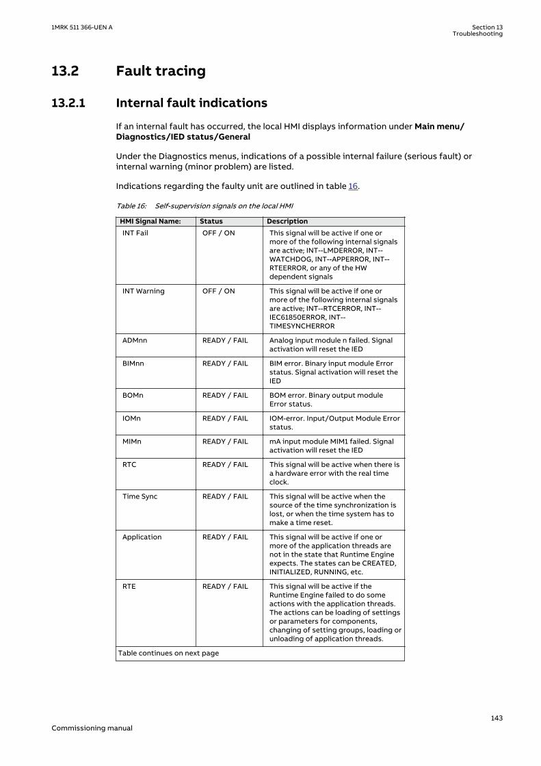
13.2 Fault tracingIP8765-1 v1
13.2.1 Internal fault indicationsM11763-2 v7
If an internal fault has occurred, the local HMI displays information under Main menu/Diagnostics/IED status/General
Under the Diagnostics menus, indications of a possible internal failure (serious fault) orinternal warning (minor problem) are listed.
Indications regarding the faulty unit are outlined in table 16.
Table 16: Self-supervision signals on the local HMI
HMI Signal Name: Status Description
INT Fail OFF / ON This signal will be active if one ormore of the following internal signalsare active; INT--LMDERROR, INT--WATCHDOG, INT--APPERROR, INT--RTEERROR, or any of the HWdependent signals
INT Warning OFF / ON This signal will be active if one ormore of the following internal signalsare active; INT--RTCERROR, INT--IEC61850ERROR, INT--TIMESYNCHERROR
ADMnn READY / FAIL Analog input module n failed. Signalactivation will reset the IED
BIMnn READY / FAIL BIM error. Binary input module Errorstatus. Signal activation will reset theIED
BOMn READY / FAIL BOM error. Binary output moduleError status.
IOMn READY / FAIL IOM-error. Input/Output Module Errorstatus.
MIMn READY / FAIL mA input module MIM1 failed. Signalactivation will reset the IED
RTC READY / FAIL This signal will be active when there isa hardware error with the real timeclock.
Time Sync READY / FAIL This signal will be active when thesource of the time synchronization islost, or when the time system has tomake a time reset.
Application READY / FAIL This signal will be active if one ormore of the application threads arenot in the state that Runtime Engineexpects. The states can be CREATED,INITIALIZED, RUNNING, etc.
RTE READY / FAIL This signal will be active if theRuntime Engine failed to do someactions with the application threads.The actions can be loading of settingsor parameters for components,changing of setting groups, loading orunloading of application threads.
Table continues on next page
1MRK 511 366-UEN A Section 13Troubleshooting
143Commissioning manual

HMI Signal Name: Status Description
IEC61850 READY / FAIL This signal will be active if the IEC61850 stack did not succeed in someactions like reading IEC 61850configuration, startup etc.
LMD READY / FAIL LON network interface, MIP/DPS, is inan unrecoverable error state.
LDCMxxx READY / FAIL Line Differential Communication Errorstatus
OEM READY / FAIL Optical Ethernet Module error status
Also the internal signals, such as INT--FAIL and INT--WARNING can be connected to binaryoutput contacts for signalling to a control room.
In the IED Status - Information, the present information from the self-supervision function canbe viewed. Indications of failure or warnings for each hardware module are provided, as well asinformation about the external time synchronization and the internal clock. All according totable 16. Loss of time synchronization can be considered as a warning only. The IED has fullfunctionality without time synchronization.
When settings are changed in the IED, the protection and control applications restart in orderto take effect of the changes. During restart, internal events get generated and Runtime Apperror will be displayed. These events are only indications and will be for short duration duringthe restart.
IED will not be operational during applications restart.
13.2.2 Using front-connected PCM11763-203 v4
When an internal fault has occurred, extensive information about the fault can be retrievedfrom the list of internal events available in the SMS part:
TRM-STAT TermStatus - Internal Events
The list of internal events provides valuable information, which can be used duringcommissioning and fault tracing.
The internal events are time tagged with a resolution of 1ms and stored in a list. The list canstore up to 40 events. The list is based on the FIFO principle, when it is full, the oldest event isoverwritten. The list cannot be cleared and its content cannot be erased.
The internal events in this list not only refer to faults in the IED, but also to other activities,such as change of settings, clearing of disturbance reports, and loss of external timesynchronization.
The information can only be retrieved from the Parameter Setting software package. The PCcan be connected either to the port at the front or at the rear of the IED.
These events are logged as internal events.
Section 13 1MRK 511 366-UEN ATroubleshooting
144Commissioning manual

Table 17: Events available for the internal event list in the IED
Event message: Description Generating signal:
INT--FAIL Off Internal fail status INT--FAIL (reset event)
INT--FAIL INT--FAIL (set event)
INT--WARNING Off Internal warning status lNT--WARNING (reset event)
INT--WARNING lNT--WARNING (set event)
IOn--Error Off In/Out module No. n status IOn--Error (reset event)
IOn--Error IOn--Error (set event)
ADMn-Error Off Analog/Digital module No. nstatus
ADMn-Error (reset event)
ADMn-Error ADMn-Error (set event)
MIM1-Error Off mA-input module status MIM1-Error (reset event)
MIM1-Error MIM1-Error (set event)
INT--RTC Off Real Time Clock (RTC) status INT--RTC (reset event)
INT--RTC INT--RTC (set event)
INT--TSYNC Off External time synchronizationstatus
INT--TSYNC (reset event)
INT--TSYNC INT--TSYNC (set event)
INT--SETCHGD Any settings in IED changed
DRPC-CLEARED All disturbances inDisturbance report cleared
The events in the internal event list are time tagged with a resolution of 1ms.
This means that, when using the PC for fault tracing, it provides information on the:
• Module that should be changed.• Sequence of faults, if more than one unit is faulty.• Exact time when the fault occurred.
13.2.3 Diagnosing the IED status via the LHMI hint menuGUID-7E8503E9-441B-487A-9CD7-B43463D1CAE5 v3
In order to help the user, there is an LHMI page labeled ‘Hints’. This page is located under Mainmenu/Diagnostics/IED status/Hints. For each activated hint there is a headline. From theheadline view, an explanation page can be entered, giving the user more information and hintsabout the particular topic.
For example, if there is a configuration to use IEC 61850 9–2 analog data, but no data arriveson the access point, then the IED will use substituted data and most protection functions willbe blocked. This condition will be indicated with a sub-menu under Hints, where details aboutthis condition are shown. The Hint menu is a way to assist the user in troubleshooting.
The Hint menu is currently only available in English. All the entries are in English,regardless of which language is selected.
The supported list of hints are as follows:
1MRK 511 366-UEN A Section 13Troubleshooting
145Commissioning manual

Table 18: Hint menu
Headline Explanation
Incorrect setting of SyncLostMode There are two explanations possible: SyncLostMode is set to Block, no time source isconfigured to achieve the required accuracy. Unless ahigh accuracy time source is selected, the functiondependent on high time accuracy will be blocked.
SyncLostMode is set to BlockOnLostUTC, but there isno UTC capable synch source (GPS, IRIG-B) used.Unless a UTC capable time source is selected, thefunction dependent on high time accuracy will beblocked.
Sampled value substituted <Access Point><Hardware Module Identifier><svID>Where the Hardware Module Identifier is the same asgiven in PCM600, e.g. AP1: MU1_9201 svID:<ABB_MU0101>
Time diff: IED vs Sampled value <Access Point><Hardware Module Identifier><svID>Where the Hardware Module Identifier is the same asgiven in PCM600, e.g. AP1: MU1_9201 svID:<ABB_MU0101>
Frequency diff: IED vs Sampled value <Access Point><Hardware Module Identifier><svID>Where the Hardware Module Identifier is the same asgiven in PCM600, e.g. AP1: MU1_9201 svID:<ABB_MU0101>
Wrong cycle time for PMU report Wrong cycle time on SMAI or 3PHSUM blockconnected to Phasor Report block. The SMAI or3PHSUM block should have the same cycle time asthat of Phasor Report.
PMU not connected to 3ph output The PMU phasor report input(s) must be connectedto the 3ph output of SMAI or 3PHSU.
Invalid value set for PMU Parameters There are two explanations possible: Check if the following parameters are set correctly onPMUREPORT: ReportRate or SvcClass or parameterPRIMVAL:1.FrequencySel is not set as 50Hz / 60Hz.
Check if the following parameters are set correctly onPMUREPORT: ReportRate or SvcClass or RptTimetagor parameter PRIMVAL:1.FrequencySel is not set as50Hz / 60Hz.
Invalid phase angle reference The selected PhaseAngleRef corresponds to ananalog channel that is not configured. Pleaseconfigure a valid reference channel.
GOOSE is configured on a disabled port At least one of the access points configured forGOOSE is disabled. The port can be disabled eitherthrough changing the access point operation to offor by unchecking the GOOSE protocol from theaccess point in the Ethernet configuration in PCM600or LHMI.Please enable GOOSE on access points: AP_FRONT,AP_1
LDCM not running the application image <slot number> is running the factory image insteadof the application image. The factory image is olderand does not contain the latest updates and fixes.Please reboot the IED. If the problem persists updatethe LDCM firmware or replace the board.
LDCM version is not accepted <device name> firmware version <version string> isnot accepted. The minimum accepted version is<version string>.Please update the LDCM firmware or replace theboard.
Table continues on next page
Section 13 1MRK 511 366-UEN ATroubleshooting
146Commissioning manual
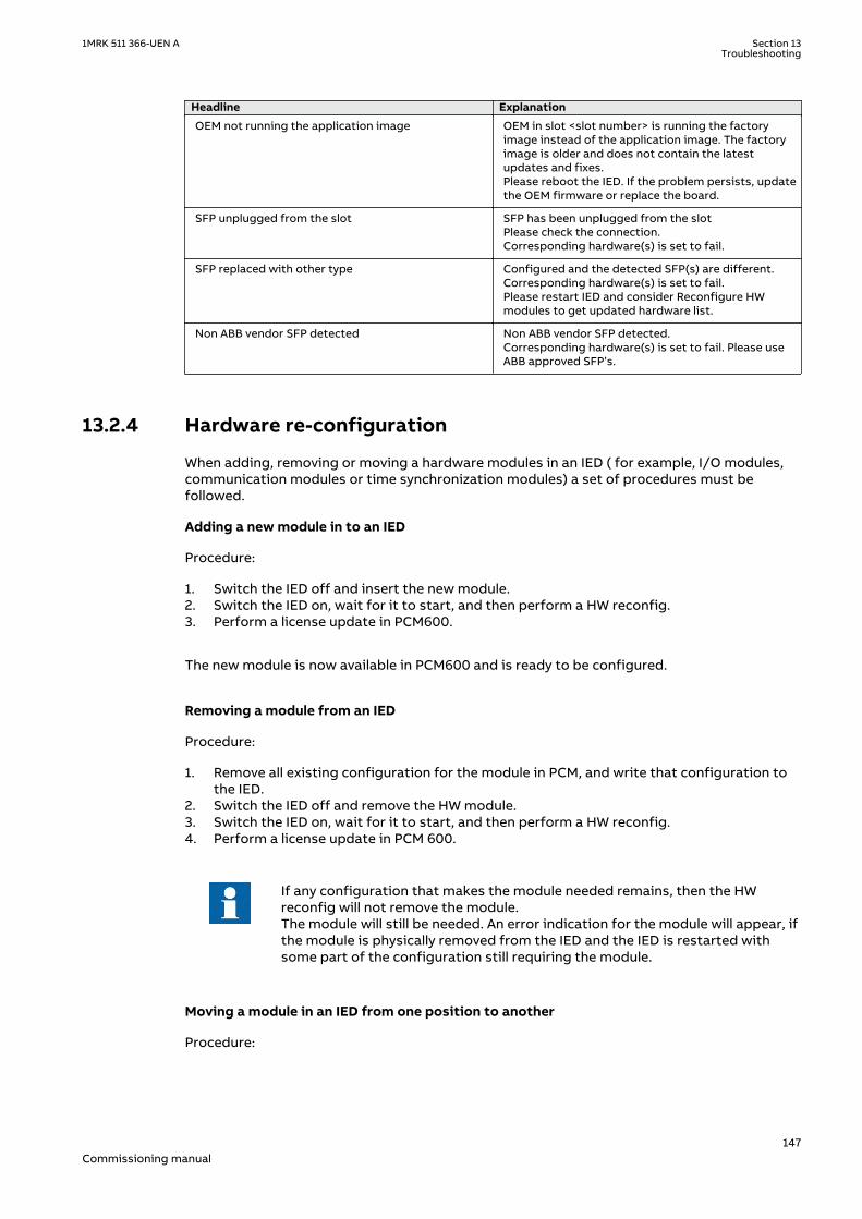
Headline Explanation
OEM not running the application image OEM in slot <slot number> is running the factoryimage instead of the application image. The factoryimage is older and does not contain the latestupdates and fixes.Please reboot the IED. If the problem persists, updatethe OEM firmware or replace the board.
SFP unplugged from the slot SFP has been unplugged from the slotPlease check the connection.Corresponding hardware(s) is set to fail.
SFP replaced with other type Configured and the detected SFP(s) are different.Corresponding hardware(s) is set to fail.Please restart IED and consider Reconfigure HWmodules to get updated hardware list.
Non ABB vendor SFP detected Non ABB vendor SFP detected.Corresponding hardware(s) is set to fail. Please useABB approved SFP’s.
13.2.4 Hardware re-configurationGUID-334C5D8B-F383-4CDE-9850-659ED6B405DC v1
When adding, removing or moving a hardware modules in an IED ( for example, I/O modules,communication modules or time synchronization modules) a set of procedures must befollowed.
Adding a new module in to an IED
Procedure:
1. Switch the IED off and insert the new module.2. Switch the IED on, wait for it to start, and then perform a HW reconfig.3. Perform a license update in PCM600.
The new module is now available in PCM600 and is ready to be configured.
Removing a module from an IED
Procedure:
1. Remove all existing configuration for the module in PCM, and write that configuration tothe IED.
2. Switch the IED off and remove the HW module.3. Switch the IED on, wait for it to start, and then perform a HW reconfig.4. Perform a license update in PCM 600.
If any configuration that makes the module needed remains, then the HWreconfig will not remove the module.The module will still be needed. An error indication for the module will appear, ifthe module is physically removed from the IED and the IED is restarted withsome part of the configuration still requiring the module.
Moving a module in an IED from one position to another
Procedure:
1MRK 511 366-UEN A Section 13Troubleshooting
147Commissioning manual

1. Remove all existing configuration for the module in PCM, and write that configuration tothe IED.
2. Switch the IED off and move the HW module.3. Switch the IED on, wait for it to start, and then perform a HW reconfig.4. Perform a license update in PCM600.
The new module is now available in PCM600 at the new position and is ready to be configured.
13.3 Repair instructionIP8767-1 v1
M11764-2 v2
Never disconnect the secondary connection of a current transformer circuitwithout short-circuiting the transformer’s secondary winding. Operating acurrent transformer with the secondary winding open will cause a massivepotential build up that may damage the transformer and may cause injuries tohumans.
Never connect or disconnect a wire and/or a connector to or from a IED duringnormal service. Hazardous voltages and currents are present that may belethal. Operation may be disrupted and IED and measuring circuitry may bedamaged.
M11764-10 v1
An alternative is to open the IED and send only the faulty circuit board to ABB for repair. Whena printed circuit board is sent to ABB, it must always be placed in a metallic, ESD-proof,protection bag. The user can also purchase separate replacement modules.
Strictly follow the company and country safety regulations.
M11766-4 v2
Most electronic components are sensitive to electrostatic discharge and latent damage mayoccur. Please observe usual procedures for handling electronics and also use an ESD wriststrap. A semi-conducting layer must be placed on the workbench and connected to earth.
Disassemble and reassemble the IED accordingly:
1. Switch off the dc supply.2. Short-circuit the current transformers and disconnect all current and voltage connections
from the IED.3. Disconnect all signal wires by removing the female connectors.4. Disconnect the optical fibers.5. Unscrew the main back plate of the IED.6. If the transformer module is to be changed:
• Remove the IED from the panel if necessary.• Remove the rear plate of the IED.• Remove the front plate.• Remove the screws of the transformer input module, both front and rear.
7. Pull out the faulty module.8. Check that the new module has a correct identity number.9. Check that the springs on the card rail are connected to the corresponding metallic area
on the circuit board when the new module is inserted.10. Reassemble the IED.
Section 13 1MRK 511 366-UEN ATroubleshooting
148Commissioning manual

If the IED has been calibrated with the system inputs, the calibration procedure must beperformed again to maintain the total system accuracy.
13.4 Repair supportM11768-3 v3
If an IED needs to be repaired, the whole IED must be removed and sent to an ABB LogisticCenter. Before returning the material, an inquiry must be sent to the ABB Logistic Center.
e-mail: [email protected]
13.5 MaintenanceM11769-3 v2
The IED is self-supervised. No special maintenance is required.
Instructions from the power network company and other maintenance directives valid formaintenance of the power system must be followed.
1MRK 511 366-UEN A Section 13Troubleshooting
149Commissioning manual

150

Section 14 GlossaryM14893-1 v18
AC Alternating current
ACC Actual channel
ACT Application configuration tool within PCM600
A/D converter Analog-to-digital converter
ADBS Amplitude deadband supervision
ADM Analog digital conversion module, with time synchronization
AI Analog input
ANSI American National Standards Institute
AR Autoreclosing
ASCT Auxiliary summation current transformer
ASD Adaptive signal detection
ASDU Application service data unit
AWG American Wire Gauge standard
BBP Busbar protection
BFOC/2,5 Bayonet fiber optic connector
BFP Breaker failure protection
BI Binary input
BIM Binary input module
BOM Binary output module
BOS Binary outputs status
BR External bistable relay
BS British Standards
BSR Binary signal transfer function, receiver blocks
BST Binary signal transfer function, transmit blocks
C37.94 IEEE/ANSI protocol used when sending binary signals between IEDs
CAN Controller Area Network. ISO standard (ISO 11898) for serialcommunication
CB Circuit breaker
CBM Combined backplane module
CCITT Consultative Committee for International Telegraph and Telephony. AUnited Nations-sponsored standards body within the InternationalTelecommunications Union.
CCM CAN carrier module
CCVT Capacitive Coupled Voltage Transformer
Class C Protection Current Transformer class as per IEEE/ ANSI
CMPPS Combined megapulses per second
CMT Communication Management tool in PCM600
1MRK 511 366-UEN A Section 14Glossary
151Commissioning manual

CO cycle Close-open cycle
Codirectional Way of transmitting G.703 over a balanced line. Involves two twistedpairs making it possible to transmit information in both directions
COM Command
COMTRADE Standard Common Format for Transient Data Exchange format forDisturbance recorder according to IEEE/ANSI C37.111, 1999 / IEC60255-24
Contra-directional Way of transmitting G.703 over a balanced line. Involves four twistedpairs, two of which are used for transmitting data in both directionsand two for transmitting clock signals
COT Cause of transmission
CPU Central processing unit
CR Carrier receive
CRC Cyclic redundancy check
CROB Control relay output block
CS Carrier send
CT Current transformer
CU Communication unit
CVT or CCVT Capacitive voltage transformer
DAR Delayed autoreclosing
DARPA Defense Advanced Research Projects Agency (The US developer of theTCP/IP protocol etc.)
DBDL Dead bus dead line
DBLL Dead bus live line
DC Direct current
DFC Data flow control
DFT Discrete Fourier transform
DHCP Dynamic Host Configuration Protocol
DIP-switch Small switch mounted on a printed circuit board
DI Digital input
DLLB Dead line live bus
DNP Distributed Network Protocol as per IEEE Std 1815-2012
DR Disturbance recorder
DRAM Dynamic random access memory
DRH Disturbance report handler
DSP Digital signal processor
DTT Direct transfer trip scheme
ECT Ethernet configuration tool
EHV network Extra high voltage network
EIA Electronic Industries Association
EMC Electromagnetic compatibility
EMF Electromotive force
Section 14 1MRK 511 366-UEN AGlossary
152Commissioning manual
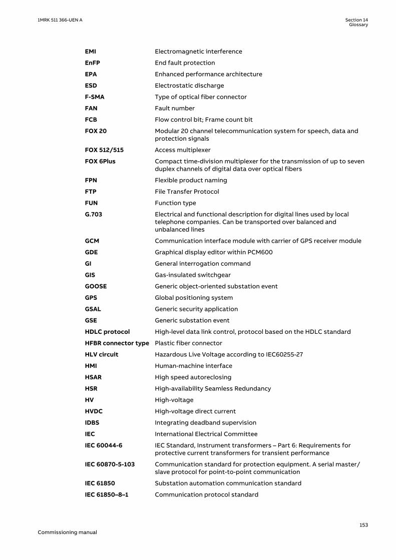
EMI Electromagnetic interference
EnFP End fault protection
EPA Enhanced performance architecture
ESD Electrostatic discharge
F-SMA Type of optical fiber connector
FAN Fault number
FCB Flow control bit; Frame count bit
FOX 20 Modular 20 channel telecommunication system for speech, data andprotection signals
FOX 512/515 Access multiplexer
FOX 6Plus Compact time-division multiplexer for the transmission of up to sevenduplex channels of digital data over optical fibers
FPN Flexible product naming
FTP File Transfer Protocol
FUN Function type
G.703 Electrical and functional description for digital lines used by localtelephone companies. Can be transported over balanced andunbalanced lines
GCM Communication interface module with carrier of GPS receiver module
GDE Graphical display editor within PCM600
GI General interrogation command
GIS Gas-insulated switchgear
GOOSE Generic object-oriented substation event
GPS Global positioning system
GSAL Generic security application
GSE Generic substation event
HDLC protocol High-level data link control, protocol based on the HDLC standard
HFBR connector type Plastic fiber connector
HLV circuit Hazardous Live Voltage according to IEC60255-27
HMI Human-machine interface
HSAR High speed autoreclosing
HSR High-availability Seamless Redundancy
HV High-voltage
HVDC High-voltage direct current
IDBS Integrating deadband supervision
IEC International Electrical Committee
IEC 60044-6 IEC Standard, Instrument transformers – Part 6: Requirements forprotective current transformers for transient performance
IEC 60870-5-103 Communication standard for protection equipment. A serial master/slave protocol for point-to-point communication
IEC 61850 Substation automation communication standard
IEC 61850–8–1 Communication protocol standard
1MRK 511 366-UEN A Section 14Glossary
153Commissioning manual
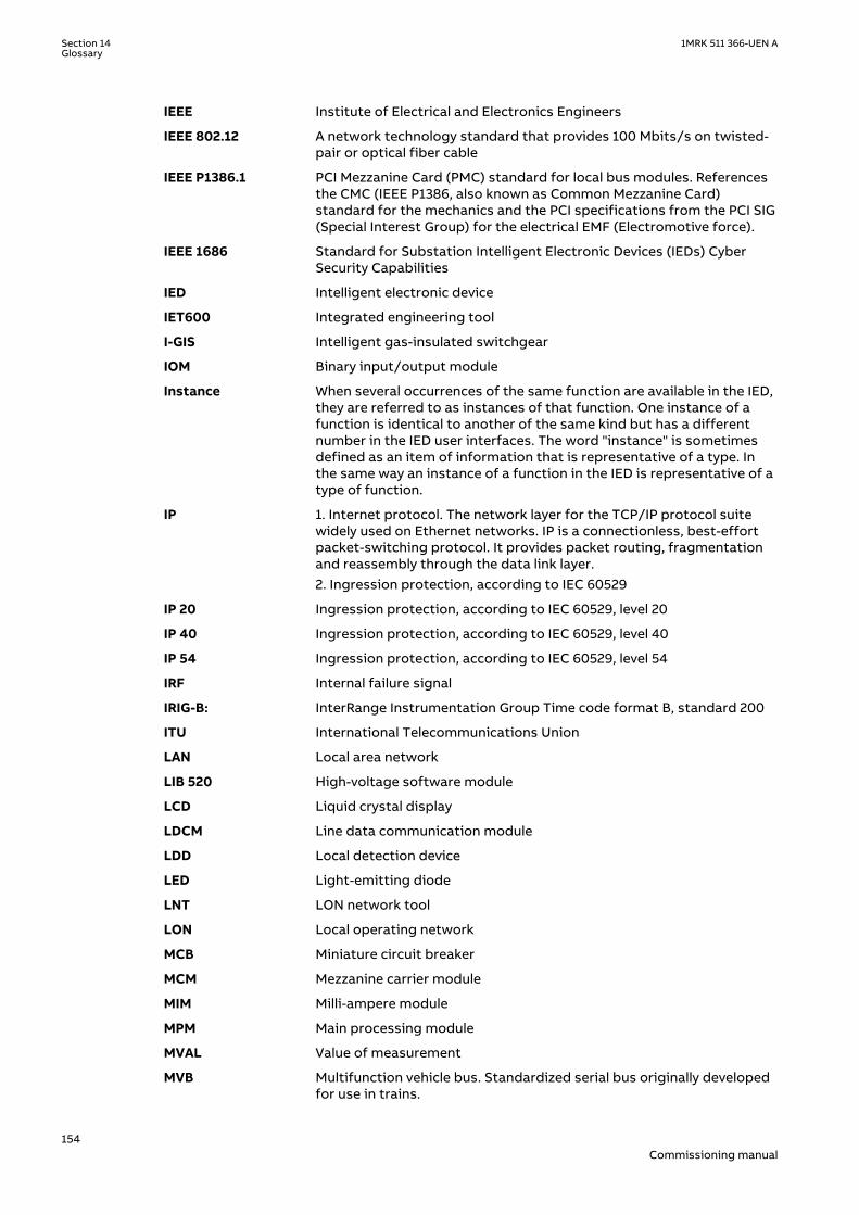
IEEE Institute of Electrical and Electronics Engineers
IEEE 802.12 A network technology standard that provides 100 Mbits/s on twisted-pair or optical fiber cable
IEEE P1386.1 PCI Mezzanine Card (PMC) standard for local bus modules. Referencesthe CMC (IEEE P1386, also known as Common Mezzanine Card)standard for the mechanics and the PCI specifications from the PCI SIG(Special Interest Group) for the electrical EMF (Electromotive force).
IEEE 1686 Standard for Substation Intelligent Electronic Devices (IEDs) CyberSecurity Capabilities
IED Intelligent electronic device
IET600 Integrated engineering tool
I-GIS Intelligent gas-insulated switchgear
IOM Binary input/output module
Instance When several occurrences of the same function are available in the IED,they are referred to as instances of that function. One instance of afunction is identical to another of the same kind but has a differentnumber in the IED user interfaces. The word "instance" is sometimesdefined as an item of information that is representative of a type. Inthe same way an instance of a function in the IED is representative of atype of function.
IP 1. Internet protocol. The network layer for the TCP/IP protocol suitewidely used on Ethernet networks. IP is a connectionless, best-effortpacket-switching protocol. It provides packet routing, fragmentationand reassembly through the data link layer.2. Ingression protection, according to IEC 60529
IP 20 Ingression protection, according to IEC 60529, level 20
IP 40 Ingression protection, according to IEC 60529, level 40
IP 54 Ingression protection, according to IEC 60529, level 54
IRF Internal failure signal
IRIG-B: InterRange Instrumentation Group Time code format B, standard 200
ITU International Telecommunications Union
LAN Local area network
LIB 520 High-voltage software module
LCD Liquid crystal display
LDCM Line data communication module
LDD Local detection device
LED Light-emitting diode
LNT LON network tool
LON Local operating network
MCB Miniature circuit breaker
MCM Mezzanine carrier module
MIM Milli-ampere module
MPM Main processing module
MVAL Value of measurement
MVB Multifunction vehicle bus. Standardized serial bus originally developedfor use in trains.
Section 14 1MRK 511 366-UEN AGlossary
154Commissioning manual
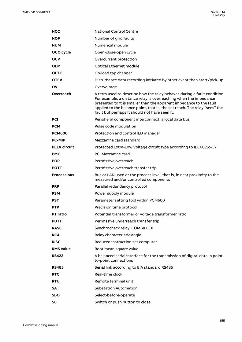
NCC National Control Centre
NOF Number of grid faults
NUM Numerical module
OCO cycle Open-close-open cycle
OCP Overcurrent protection
OEM Optical Ethernet module
OLTC On-load tap changer
OTEV Disturbance data recording initiated by other event than start/pick-up
OV Overvoltage
Overreach A term used to describe how the relay behaves during a fault condition.For example, a distance relay is overreaching when the impedancepresented to it is smaller than the apparent impedance to the faultapplied to the balance point, that is, the set reach. The relay “sees” thefault but perhaps it should not have seen it.
PCI Peripheral component interconnect, a local data bus
PCM Pulse code modulation
PCM600 Protection and control IED manager
PC-MIP Mezzanine card standard
PELV circuit Protected Extra-Low Voltage circuit type according to IEC60255-27
PMC PCI Mezzanine card
POR Permissive overreach
POTT Permissive overreach transfer trip
Process bus Bus or LAN used at the process level, that is, in near proximity to themeasured and/or controlled components
PRP Parallel redundancy protocol
PSM Power supply module
PST Parameter setting tool within PCM600
PTP Precision time protocol
PT ratio Potential transformer or voltage transformer ratio
PUTT Permissive underreach transfer trip
RASC Synchrocheck relay, COMBIFLEX
RCA Relay characteristic angle
RISC Reduced instruction set computer
RMS value Root mean square value
RS422 A balanced serial interface for the transmission of digital data in point-to-point connections
RS485 Serial link according to EIA standard RS485
RTC Real-time clock
RTU Remote terminal unit
SA Substation Automation
SBO Select-before-operate
SC Switch or push button to close
1MRK 511 366-UEN A Section 14Glossary
155Commissioning manual
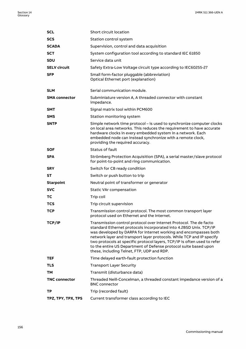
SCL Short circuit location
SCS Station control system
SCADA Supervision, control and data acquisition
SCT System configuration tool according to standard IEC 61850
SDU Service data unit
SELV circuit Safety Extra-Low Voltage circuit type according to IEC60255-27
SFP Small form-factor pluggable (abbreviation)Optical Ethernet port (explanation)
SLM Serial communication module.
SMA connector Subminiature version A, A threaded connector with constantimpedance.
SMT Signal matrix tool within PCM600
SMS Station monitoring system
SNTP Simple network time protocol – is used to synchronize computer clockson local area networks. This reduces the requirement to have accuratehardware clocks in every embedded system in a network. Eachembedded node can instead synchronize with a remote clock,providing the required accuracy.
SOF Status of fault
SPA Strömberg Protection Acquisition (SPA), a serial master/slave protocolfor point-to-point and ring communication.
SRY Switch for CB ready condition
ST Switch or push button to trip
Starpoint Neutral point of transformer or generator
SVC Static VAr compensation
TC Trip coil
TCS Trip circuit supervision
TCP Transmission control protocol. The most common transport layerprotocol used on Ethernet and the Internet.
TCP/IP Transmission control protocol over Internet Protocol. The de factostandard Ethernet protocols incorporated into 4.2BSD Unix. TCP/IPwas developed by DARPA for Internet working and encompasses bothnetwork layer and transport layer protocols. While TCP and IP specifytwo protocols at specific protocol layers, TCP/IP is often used to referto the entire US Department of Defense protocol suite based uponthese, including Telnet, FTP, UDP and RDP.
TEF Time delayed earth-fault protection function
TLS Transport Layer Security
TM Transmit (disturbance data)
TNC connector Threaded Neill-Concelman, a threaded constant impedance version of aBNC connector
TP Trip (recorded fault)
TPZ, TPY, TPX, TPS Current transformer class according to IEC
Section 14 1MRK 511 366-UEN AGlossary
156Commissioning manual

TRM Transformer Module. This module transforms currents and voltagestaken from the process into levels suitable for further signalprocessing.
TYP Type identification
UMT User management tool
Underreach A term used to describe how the relay behaves during a fault condition.For example, a distance relay is underreaching when the impedancepresented to it is greater than the apparent impedance to the faultapplied to the balance point, that is, the set reach. The relay does not“see” the fault but perhaps it should have seen it. See also Overreach.
UTC Coordinated Universal Time. A coordinated time scale, maintained bythe Bureau International des Poids et Mesures (BIPM), which forms thebasis of a coordinated dissemination of standard frequencies and timesignals. UTC is derived from International Atomic Time (TAI) by theaddition of a whole number of "leap seconds" to synchronize it withUniversal Time 1 (UT1), thus allowing for the eccentricity of the Earth'sorbit, the rotational axis tilt (23.5 degrees), but still showing the Earth'sirregular rotation, on which UT1 is based. The Coordinated UniversalTime is expressed using a 24-hour clock, and uses the Gregoriancalendar. It is used for aeroplane and ship navigation, where it is alsosometimes known by the military name, "Zulu time." "Zulu" in thephonetic alphabet stands for "Z", which stands for longitude zero.
UV Undervoltage
WEI Weak end infeed logic
VT Voltage transformer
X.21 A digital signalling interface primarily used for telecom equipment
3IO Three times zero-sequence current.Often referred to as the residual orthe earth-fault current
3UO Three times the zero sequence voltage. Often referred to as theresidual voltage or the neutral point voltage
1MRK 511 366-UEN A Section 14Glossary
157Commissioning manual

158

159

ABB ABSubstation Automation ProductsSE-721 59 Västerås, SwedenPhone +46 (0) 21 32 50 00
www.abb.com/substationautomation
© Copyright 2016 ABB.All rights reserved.
Scan this QR code to visit our website
1MR
K 5
11 3
66-U
EN


![Presentation ABB Phasor [Recovered]](https://img.pdfslide.us/doc/110x75/55cf8527550346484b8b5387/presentation-abb-phasor-recovered.jpg)