Embed Size (px)
Citation preview
Reliance Standard & Custom Components
RelianceInstrumentation Gears
GE1ANov 03
from
Schlenker Enterprises, Ltd
Schlenker Ent. Ltd. Sales : Phone:708.449.5700 Fax: 708.449.5703www.schlenkent.com [email protected]
Associated ProductsStandard Gear Range
C2
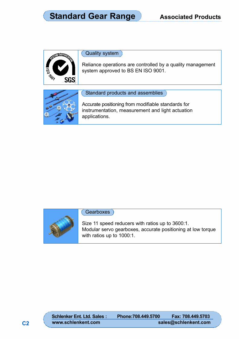
Reliance operations are controlled by a quality managementsystem approved to BS EN ISO 9001.
Accurate positioning from modifiable standards forinstrumentation, measurement and light actuationapplications.
Size 11 speed reducers with ratios up to 3600:1.Modular servo gearboxes, accurate positioning at low torquewith ratios up to 1000:1.
Quality system
Standard products and assemblies
Gearboxes
Index Standard Gear Range
1
Basic part numbering .................................................... 2
Gear pairs...................................................................... 3
Anti-backlash Reli-a-Grip™ clamp hub pinions..............4
Anti-backlash Reli-a-Grip™ clamp hub gears .............. 6
Anti-backlash clamp hub pinions - Miniature .............. 10Anti-backlash clamp hub pinions ................................ 12
Anti-backlash clamp hub gears .................................. 14
Anti-backlash pin hub pinions .................................... 18
Anti-backlash pin hub gears........................................ 20
Reli-a-Grip™ clamp hub spur gears .......................... 24
Clamp hub spur gears..................................................28
Pin hub spur gears ...................................................... 32
Hubless spur gears .................................................... 36
Anti-backlash synchro gears ...................................... 38
Bevel gears ................................................................ 40
Worms and wheels .................................................... 43
Worm gear formulae.................................................... 45
Pinion shafts .............................................................. 46
Hardened pin hub spur gears .................................... 48
Gears to special order ................................................ 50
Gear clamps ................................................................52
Standard belts and pulleys ..........................................54
Technical information .................................................. 55
Page title Page
Schlenker Ent. Ltd. Sales : Phone:708.449.5700 Fax: 708.449.5703www.schlenkent.com [email protected]
Basic Part NumberingGear Range
2
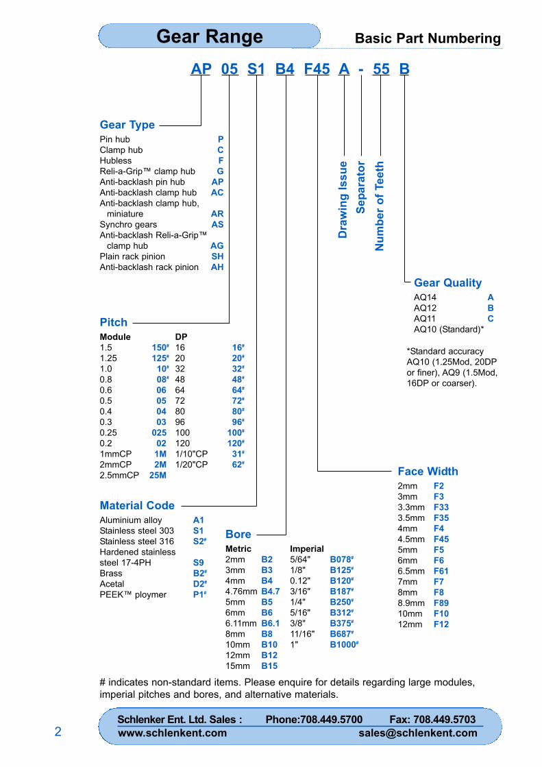
AP 05 S1 B4 F45 A - 55 B
Pin hubClamp hubHublessReli-a-Grip™ clamp hubAnti-backlash pin hubAnti-backlash clamp hubAnti-backlash clamp hub,
miniatureSynchro gearsAnti-backlash Reli-a-Grip™
clamp hubPlain rack pinionAnti-backlash rack pinion
PCFG
APAC
ARAS
AGSHAH
Gear Type
PitchModule1.51.251.00.80.60.50.40.30.250.21mmCP2mmCP2.5mmCP
150#
125#
10#
08#
06 050403
025021M2M
25M
Material CodeAluminium alloyStainless steel 303Stainless steel 316Hardened stainlesssteel 17-4PHBrassAcetalPEEK™ ploymer
A1S1S2#
S9B2#
D2#
P1#
BoreMetric2mm3mm4mm4.76mm5mm6mm6.11mm8mm10mm12mm15mm
B2B3B4B4.7B5B6B6.1B8B10B12B15
Imperial5/64"1/8"0.12"3/16"1/4"5/16"3/8"11/16"1"
B078#
B125#
B120#
B187#
B250#
B312#
B375#
B687#
B1000#
Face Width2mm3mm3.3mm3.5mm4mm4.5mm5mm6mm6.5mm7mm8mm8.9mm10mm12mm
F2F3F33F35F4F45F5F6F61F7F8F89F10F12
Dra
win
g Is
sue
Sepa
rato
rN
umbe
r of T
eeth
Gear QualityAQ14AQ12AQ11AQ10 (Standard)*
ABC
*Standard accuracyAQ10 (1.25Mod, 20DPor finer), AQ9 (1.5Mod,16DP or coarser).
DP16203248647280961001201/10"CP1/20"CP
16#
20#
32#
48#
64#
72#
80#
96#
100#
120#
31#
62#
# indicates non-standard items. Please enquire for details regarding large modules,imperial pitches and bores, and alternative materials.
Schlenker Ent. Ltd. Sales : Phone:708.449.5700 Fax: 708.449.5703www.schlenkent.com [email protected]
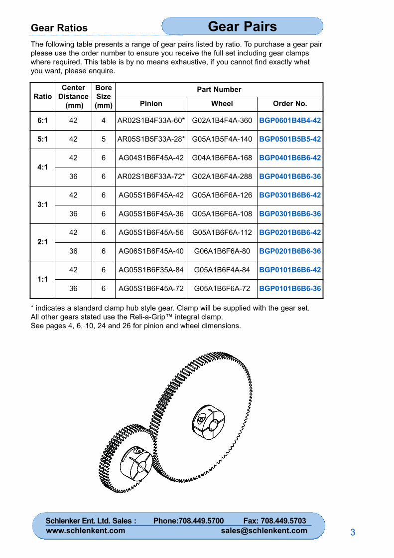
Gear Ratios Gear Pairs
3
The following table presents a range of gear pairs listed by ratio. To purchase a gear pairplease use the order number to ensure you receive the full set including gear clampswhere required. This table is by no means exhaustive, if you cannot find exactly whatyou want, please enquire.
RatioCenter
Distance(mm)
BoreSize(mm)
Part Number
Pinion Wheel Order No.
6:1 42 4 AR02S1B4F33A-60* G02A1B4F4A-360 BGP0601B4B4-42
5:1 42 5 AR05S1B5F33A-28* G05A1B5F4A-140 BGP0501B5B5-42
4:142 6 AG04S1B6F45A-42 G04A1B6F6A-168 BGP0401B6B6-42
36 6 AR02S1B6F33A-72* G02A1B6F4A-288 BGP0401B6B6-36
3:142 6 AG05S1B6F45A-42 G05A1B6F6A-126 BGP0301B6B6-42
36 6 AG05S1B6F45A-36 G05A1B6F6A-108 BGP0301B6B6-36
2:142 6 AG05S1B6F45A-56 G05A1B6F6A-112 BGP0201B6B6-42
36 6 AG06S1B6F45A-40 G06A1B6F6A-80 BGP0201B6B6-36
1:142 6 AG05S1B6F35A-84 G05A1B6F4A-84 BGP0101B6B6-42
36 6 AG05S1B6F45A-72 G05A1B6F6A-72 BGP0101B6B6-36
* indicates a standard clamp hub style gear. Clamp will be supplied with the gear set.All other gears stated use the Reli-a-Grip™ integral clamp.See pages 4, 6, 10, 24 and 26 for pinion and wheel dimensions.
Schlenker Ent. Ltd. Sales : Phone:708.449.5700 Fax: 708.449.5703www.schlenkent.com [email protected]
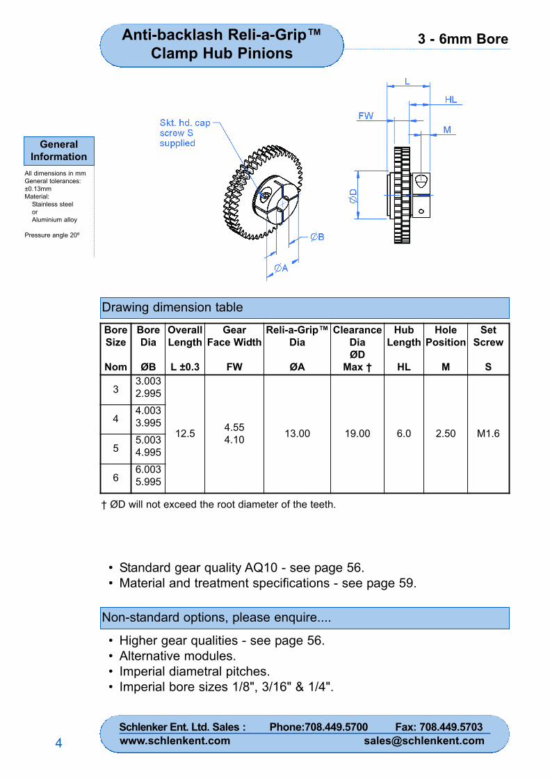
3 - 6mm BoreAnti-backlash Reli-a-Grip™Clamp Hub Pinions
GeneralInformation
All dimensions in mmGeneral tolerances:±0.13mmMaterial:
Stainless steelorAluminium alloy
Pressure angle 20º
4
Drawing dimension table
Non-standard options, please enquire....
• Standard gear quality AQ10 - see page 56.• Material and treatment specifications - see page 59.
• Higher gear qualities - see page 56.• Alternative modules.• Imperial diametral pitches.• Imperial bore sizes 1/8", 3/16" & 1/4".
BoreSize
Nom
BoreDia
ØB
OverallLength
L ±0.3
GearFace Width
FW
Reli-a-Grip™Dia
ØA
ClearanceDiaØD
Max †
HubLength
HL
HolePosition
M
SetScrew
S
33.0032.995
12.5 4.554.10 13.00 19.00 6.0 2.50 M1.6
44.0033.995
55.0034.995
66.0035.995
† ØD will not exceed the root diameter of the teeth.
Schlenker Ent. Ltd. Sales : Phone:708.449.5700 Fax: 708.449.5703www.schlenkent.com [email protected]

3 - 6mm bore Anti-backlash Reli-a-Grip™Clamp Hub Pinions
GeneralInformation
All dimensions in mmGeneral tolerances:±0.13mmMaterial:
Stainless steelorAluminium alloy
Pressure angle 20º
5
Part number selection table
Example Part No:- AG06S1B5F45A- 45
BoreSizeNom
StandardModules
Basic Part NumberStandard Materials
Number of Teeth
Min* MaxStainlessSteel
AluminiumAlloy
3
0.60.50.40.3
0.250.2
AG06S1B3F45AAG05S1B3F45AAG04S1B3F45AAG03S1B3F45A
AG025S1B3F45AAG02S1B3F45A
AG06A1B3F45AAG05A1B3F45AAG04A1B3F45AAG03A1B3F45A
AG025A1B3F45AAG02A1B3F45A
293442556580
597290
121146183
4
0.60.50.40.3
0.250.2
AG06S1B4F45AAG05S1B4F45AAG04S1B4F45AAG03S1B4F45A
AG025S1B4F45AAG02S1B4F45A
AG06A1B4F45AAG05A1B4F45AAG04A1B4F45AAG03A1B4F45A
AG025A1B4F45AAG02A1B4F45A
293442556580
597290
121146183
5
0.60.50.40.3
0.250.2
AG06S1B5F45AAG05S1B5F45AAG04S1B5F45AAG03S1B5F45A
AG025S1B5F45AAG02S1B5F45A
AG06A1B5F45AAG05A1B5F45AAG04A1B5F45AAG03A1B5F45A
AG025A1B5F45AAG02A1B5F45A
293442556580
597290
121146183
6
0.60.50.40.3
0.250.2
AG06S1B6F45AAG05S1B6F45AAG04S1B6F45AAG03S1B6F45A
AG025S1B6F45AAG02S1B6F45A
AG06A1B6F45AAG05A1B6F45AAG04A1B6F45AAG03A1B6F45A
AG025A1B6F45AAG02A1B6F45A
293442556580
597290
121146183
*For smaller numbers of teeth, see miniature anti-backlash pinions on pages 10 and 11.
Schlenker Ent. Ltd. Sales : Phone:708.449.5700 Fax: 708.449.5703www.schlenkent.com [email protected]
3 - 6mm Bore
GeneralInformation
All dimensions in mmGeneral tolerances:±0.13mmMaterial:
Stainless steelorAluminium alloy
Pressure angle 20º
6
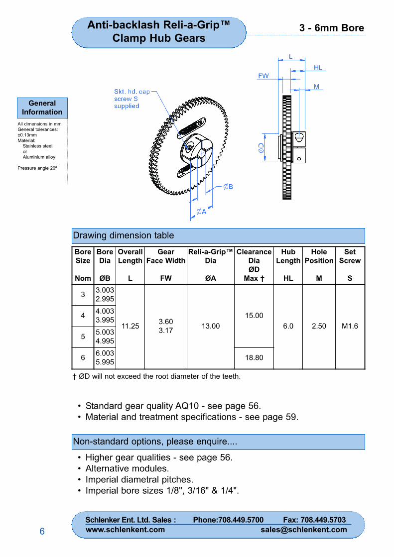
Drawing dimension table
Non-standard options, please enquire....
• Standard gear quality AQ10 - see page 56.• Material and treatment specifications - see page 59.
• Higher gear qualities - see page 56.• Alternative modules.• Imperial diametral pitches.• Imperial bore sizes 1/8", 3/16" & 1/4".
BoreSize
Nom
BoreDia
ØB
OverallLength
L
GearFace Width
FW
Reli-a-Grip™Dia
ØA
ClearanceDiaØD
Max †
HubLength
HL
HolePosition
M
SetScrew
S
3 3.0032.995
11.25 3.603.17 13.00
15.006.0 2.50 M1.6
4 4.0033.995
5 5.0034.995
6 6.0035.995 18.80
Anti-backlash Reli-a-Grip™Clamp Hub Gears
† ØD will not exceed the root diameter of the teeth.
Schlenker Ent. Ltd. Sales : Phone:708.449.5700 Fax: 708.449.5703www.schlenkent.com [email protected]
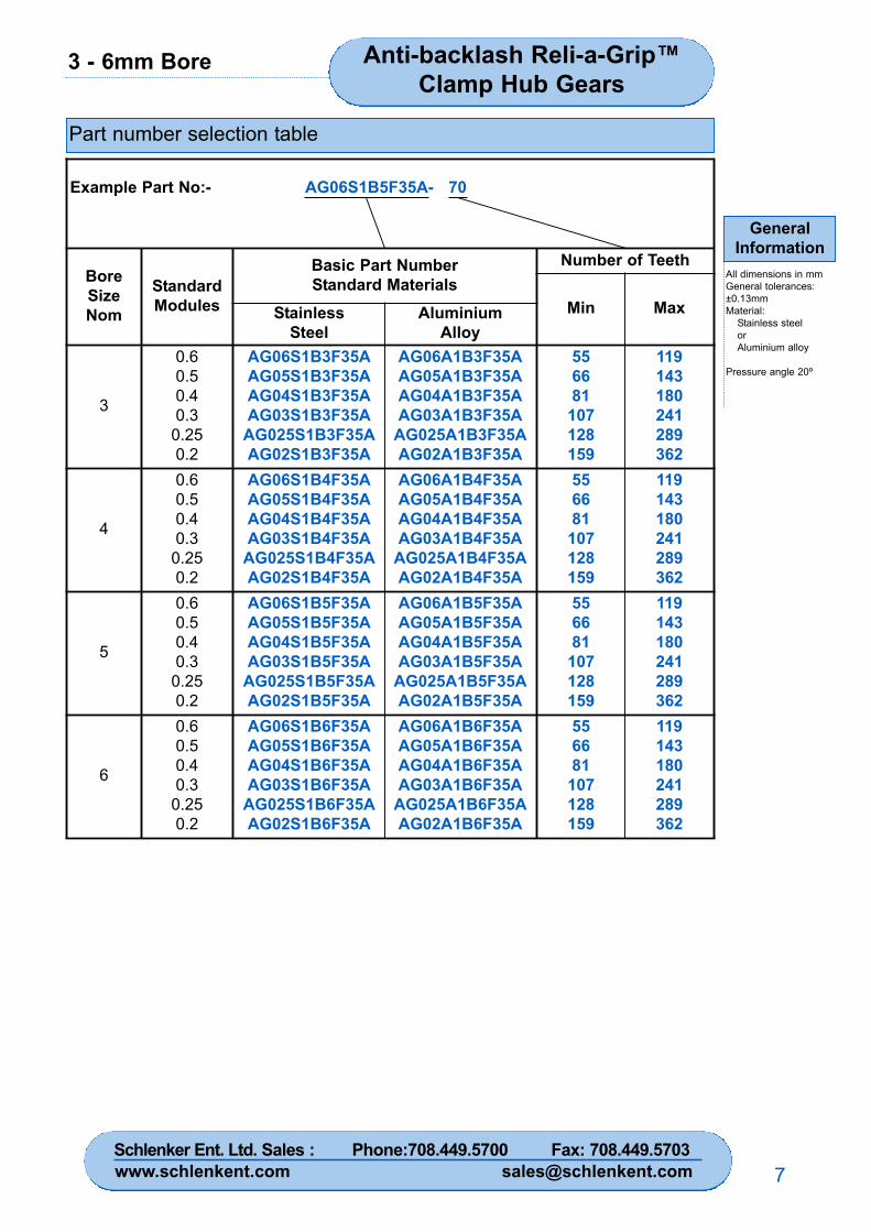
3 - 6mm Bore Anti-backlash Reli-a-Grip™Clamp Hub Gears
GeneralInformation
All dimensions in mmGeneral tolerances:±0.13mmMaterial:
Stainless steelorAluminium alloy
Pressure angle 20º
7
Part number selection table
Example Part No:- AG06S1B5F35A- 70
BoreSizeNom
StandardModules
Basic Part NumberStandard Materials
Number of Teeth
Min MaxStainlessSteel
AluminiumAlloy
3
0.60.50.40.3
0.250.2
AG06S1B3F35AAG05S1B3F35AAG04S1B3F35AAG03S1B3F35A
AG025S1B3F35AAG02S1B3F35A
AG06A1B3F35AAG05A1B3F35AAG04A1B3F35AAG03A1B3F35A
AG025A1B3F35AAG02A1B3F35A
556681
107128159
119143180241289362
4
0.60.50.40.3
0.250.2
AG06S1B4F35AAG05S1B4F35AAG04S1B4F35AAG03S1B4F35A
AG025S1B4F35AAG02S1B4F35A
AG06A1B4F35AAG05A1B4F35AAG04A1B4F35AAG03A1B4F35A
AG025A1B4F35AAG02A1B4F35A
556681
107128159
119143180241289362
5
0.60.50.40.3
0.250.2
AG06S1B5F35AAG05S1B5F35AAG04S1B5F35AAG03S1B5F35A
AG025S1B5F35AAG02S1B5F35A
AG06A1B5F35AAG05A1B5F35AAG04A1B5F35AAG03A1B5F35A
AG025A1B5F35AAG02A1B5F35A
556681
107128159
119143180241289362
6
0.60.50.40.3
0.250.2
AG06S1B6F35AAG05S1B6F35AAG04S1B6F35AAG03S1B6F35A
AG025S1B6F35AAG02S1B6F35A
AG06A1B6F35AAG05A1B6F35AAG04A1B6F35AAG03A1B6F35A
AG025A1B6F35AAG02A1B6F35A
556681
107128159
119143180241289362
Schlenker Ent. Ltd. Sales : Phone:708.449.5700 Fax: 708.449.5703www.schlenkent.com [email protected]
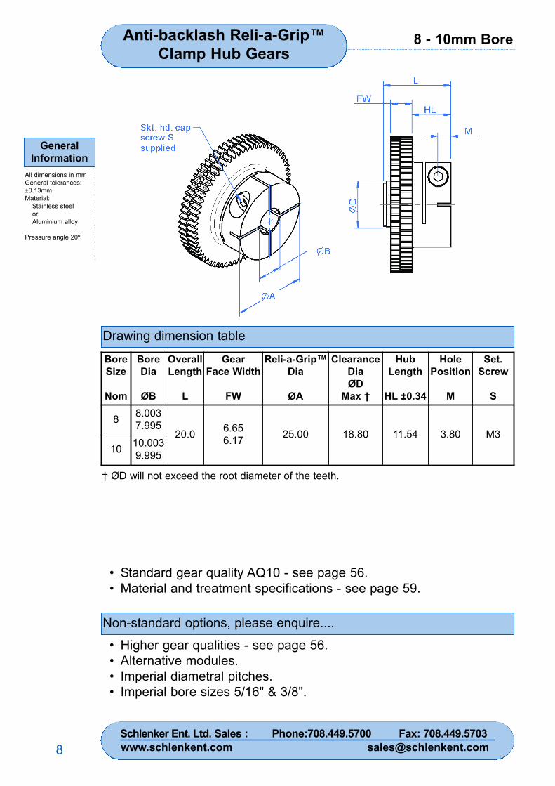
8 - 10mm Bore
GeneralInformation
All dimensions in mmGeneral tolerances:±0.13mmMaterial:
Stainless steelorAluminium alloy
Pressure angle 20º
8
Anti-backlash Reli-a-Grip™Clamp Hub Gears
Drawing dimension table
Non-standard options, please enquire....
• Standard gear quality AQ10 - see page 56.• Material and treatment specifications - see page 59.
• Higher gear qualities - see page 56.• Alternative modules.• Imperial diametral pitches.• Imperial bore sizes 5/16" & 3/8".
BoreSize
Nom
BoreDia
ØB
OverallLength
L
GearFace Width
FW
Reli-a-Grip™Dia
ØA
ClearanceDiaØD
Max †
HubLength
HL ±0.34
HolePosition
M
Set.Screw
S
8 8.0037.995
20.0 6.656.17 25.00 18.80 11.54 3.80 M3
10 10.0039.995
† ØD will not exceed the root diameter of the teeth.
Schlenker Ent. Ltd. Sales : Phone:708.449.5700 Fax: 708.449.5703www.schlenkent.com [email protected]
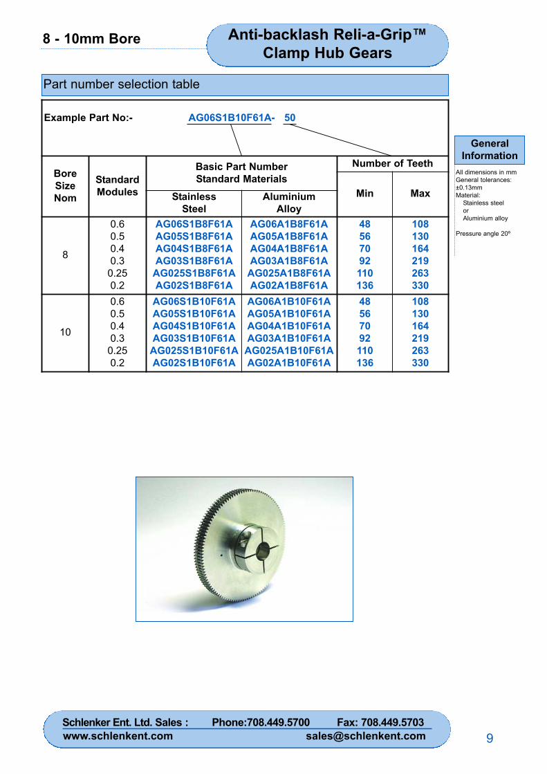
8 - 10mm Bore
GeneralInformation
All dimensions in mmGeneral tolerances:±0.13mmMaterial:
Stainless steelorAluminium alloy
Pressure angle 20º
9
Anti-backlash Reli-a-Grip™Clamp Hub Gears
Part number selection table
Example Part No:- AG06S1B10F61A- 50
BoreSizeNom
StandardModules
Basic Part NumberStandard Materials
Number of Teeth
Min MaxStainlessSteel
AluminiumAlloy
8
0.60.50.40.3
0.250.2
AG06S1B8F61AAG05S1B8F61AAG04S1B8F61AAG03S1B8F61A
AG025S1B8F61AAG02S1B8F61A
AG06A1B8F61AAG05A1B8F61AAG04A1B8F61AAG03A1B8F61A
AG025A1B8F61AAG02A1B8F61A
48567092110136
108130164219263330
10
0.60.50.40.3
0.250.2
AG06S1B10F61AAG05S1B10F61AAG04S1B10F61AAG03S1B10F61A
AG025S1B10F61AAG02S1B10F61A
AG06A1B10F61AAG05A1B10F61AAG04A1B10F61AAG03A1B10F61A
AG025A1B10F61AAG02A1B10F61A
48567092110136
108130164219263330
Schlenker Ent. Ltd. Sales : Phone:708.449.5700 Fax: 708.449.5703www.schlenkent.com [email protected]
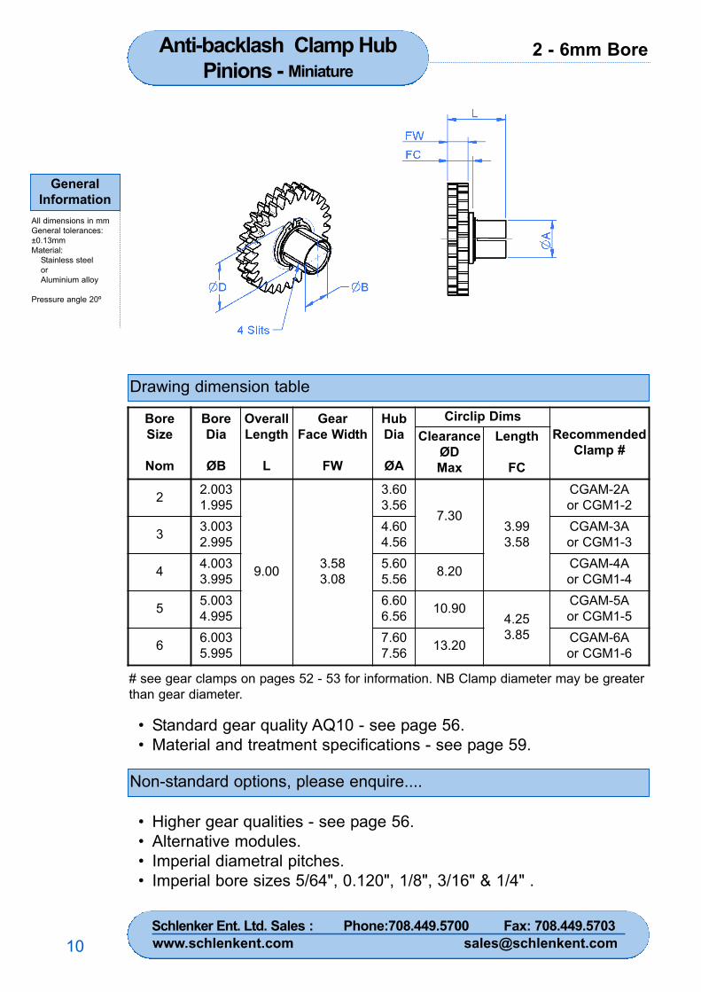
2 - 6mm BoreAnti-backlash Clamp HubPinions - Miniature
GeneralInformation
All dimensions in mmGeneral tolerances:±0.13mmMaterial:
Stainless steelorAluminium alloy
Pressure angle 20º
10
Drawing dimension table
• Standard gear quality AQ10 - see page 56.• Material and treatment specifications - see page 59.
Non-standard options, please enquire....
• Higher gear qualities - see page 56.• Alternative modules.• Imperial diametral pitches.• Imperial bore sizes 5/64", 0.120", 1/8", 3/16" & 1/4" .
BoreSize
Nom
BoreDia
ØB
OverallLength
L
GearFace Width
FW
HubDia
ØA
Circlip DimsRecommended
Clamp #Clearance
ØDMax
Length
FC
2 2.0031.995
9.00 3.583.08
3.603.56
7.303.993.58
CGAM-2Aor CGM1-2
3 3.0032.995
4.604.56
CGAM-3Aor CGM1-3
4 4.0033.995
5.605.56 8.20 CGAM-4A
or CGM1-4
5 5.0034.995
6.606.56 10.90
4.253.85
CGAM-5Aor CGM1-5
6 6.0035.995
7.607.56 13.20 CGAM-6A
or CGM1-6
# see gear clamps on pages 52 - 53 for information. NB Clamp diameter may be greaterthan gear diameter.
Schlenker Ent. Ltd. Sales : Phone:708.449.5700 Fax: 708.449.5703www.schlenkent.com [email protected]
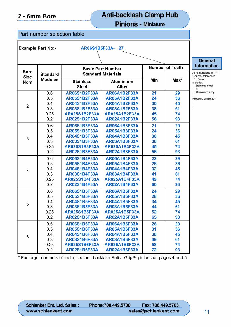
2 - 6mm Bore Anti-backlash Clamp HubPinions - Miniature
GeneralInformation
All dimensions in mmGeneral tolerances:±0.13mmMaterial:
Stainless steelorAluminium alloy
Pressure angle 20º
11
Part number selection table
Example Part No:- AR06S1B5F33A- 27
BoreSizeNom
StandardModules
Basic Part NumberStandard Materials
Number of Teeth
Min Max*StainlessSteel
AluminiumAlloy
2
0.60.50.40.3
0.250.2
AR06S1B2F33AAR05S1B2F33AAR04S1B2F33AAR03S1B2F33A
AR025S1B2F33AAR02S1B2F33A
AR06A1B2F33AAR05A1B2F33AAR04A1B2F33AAR03A1B2F33A
AR025A1B2F33AAR02A1B2F33A
212430384556
293645617493
3
0.60.50.40.3
0.250.2
AR06S1B3F33AAR05S1B3F33AAR04S1B3F33AAR03S1B3F33A
AR025S1B3F33AAR02S1B3F33A
AR06A1B3F33AAR05A1B3F33AAR04A1B3F33AAR03A1B3F33A
AR025A1B3F33AAR02A1B3F33A
212430384556
293645617493
4
0.60.50.40.3
0.250.2
AR06S1B4F33AAR05S1B4F33AAR04S1B4F33AAR03S1B4F33A
AR025S1B4F33AAR02S1B4F33A
AR06A1B4F33AAR05A1B4F33AAR04A1B4F33AAR03A1B4F33A
AR025A1B4F33AAR02A1B4F33A
222632414960
293645617493
5
0.60.50.40.3
0.250.2
AR06S1B5F33AAR05S1B5F33AAR04S1B5F33AAR03S1B5F33A
AR025S1B5F33AAR02S1B5F33A
AR06A1B5F33AAR05A1B5F33AAR04A1B5F33AAR03A1B5F33A
AR025A1B5F33AAR02A1B5F33A
242834445265
293645617493
6
0.60.50.40.3
0.250.2
AR06S1B6F33AAR05S1B6F33AAR04S1B6F33AAR03S1B6F33A
AR025S1B6F33AAR02S1B6F33A
AR06A1B6F33AAR05A1B6F33AAR04A1B6F33AAR03A1B6F33A
AR025A1B6F33AAR02A1B6F33A
263138495872
293645617493
* For larger numbers of teeth, see anti-backlash Reli-a-Grip™ pinions on pages 4 and 5.
Schlenker Ent. Ltd. Sales : Phone:708.449.5700 Fax: 708.449.5703www.schlenkent.com [email protected]
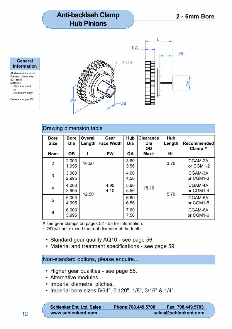
2 - 6mm BoreAnti-backlash Clamp Hub Pinions
GeneralInformation
All dimensions in mmGeneral tolerances:±0.13mmMaterial:
Stainless steelorAluminium alloy
Pressure angle 20º
12
Drawing dimension table
Non-standard options, please enquire....
• Standard gear quality AQ10 - see page 56.• Material and treatment specifications - see page 59.
• Higher gear qualities - see page 56.• Alternative modules.• Imperial diametral pitches.• Imperial bore sizes 5/64", 0.120", 1/8", 3/16" & 1/4".
BoreSize
Nom
BoreDia
ØB
OverallLength
L
GearFace Width
FW
HubDia
ØA
ClearanceDiaØD
Max†
HubLength
HL
RecommendedClamp #
2 2.0031.995 10.50
4.904.10
3.603.56
18.10
3.70 CGAM-2Aor CGM1-2
3 3.0032.995
12.50
4.604.56
5.70
CGAM-3Aor CGM1-3
4 4.0033.995
5.605.56
CGAM-4Aor CGM1-4
5 5.0034.995
6.606.56
CGAM-5Aor CGM1-5
6 6.0035.995
7.607.56
CGAM-6Aor CGM1-6
# see gear clamps on pages 52 - 53 for information.† ØD will not exceed the root diameter of the teeth.
Schlenker Ent. Ltd. Sales : Phone:708.449.5700 Fax: 708.449.5703www.schlenkent.com [email protected]
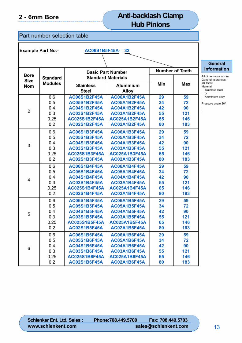
2 - 6mm Bore Anti-backlash Clamp Hub Pinions
GeneralInformation
All dimensions in mmGeneral tolerances:±0.13mmMaterial:
Stainless steelorAluminium alloy
Pressure angle 20º
13
Part number selection table
Example Part No:- AC06S1B5F45A- 32
BoreSizeNom
StandardModules
Basic Part NumberStandard Materials
Number of Teeth
Min MaxStainlessSteel
AluminiumAlloy
2
0.60.50.40.3
0.250.2
AC06S1B2F45AAC05S1B2F45AAC04S1B2F45AAC03S1B2F45A
AC025S1B2F45AAC02S1B2F45A
AC06A1B2F45AAC05A1B2F45AAC04A1B2F45AAC03A1B2F45A
AC025A1B2F45AAC02A1B2F45A
293442556580
597290
121146183
3
0.60.50.40.3
0.250.2
AC06S1B3F45AAC05S1B3F45AAC04S1B3F45AAC03S1B3F45A
AC025S1B3F45AAC02S1B3F45A
AC06A1B3F45AAC05A1B3F45AAC04A1B3F45AAC03A1B3F45A
AC025A1B3F45AAC02A1B3F45A
293442556580
597290
121146183
4
0.60.50.40.3
0.250.2
AC06S1B4F45AAC05S1B4F45AAC04S1B4F45AAC03S1B4F45A
AC025S1B4F45AAC02S1B4F45A
AC06A1B4F45AAC05A1B4F45AAC04A1B4F45AAC03A1B4F45A
AC025A1B4F45AAC02A1B4F45A
293442556580
597290
121146183
5
0.60.50.40.3
0.250.2
AC06S1B5F45AAC05S1B5F45AAC04S1B5F45AAC03S1B5F45A
AC025S1B5F45AAC02S1B5F45A
AC06A1B5F45AAC05A1B5F45AAC04A1B5F45AAC03A1B5F45A
AC025A1B5F45AAC02A1B5F45A
293442556580
597290
121146183
6
0.60.50.40.3
0.250.2
AC06S1B6F45AAC05S1B6F45AAC04S1B6F45AAC03S1B6F45A
AC025S1B6F45AAC02S1B6F45A
AC06A1B6F45AAC05A1B6F45AAC04A1B6F45AAC03A1B6F45A
AC025A1B6F45AAC02A1B6F45A
293442556580
597290
121146183
Schlenker Ent. Ltd. Sales : Phone:708.449.5700 Fax: 708.449.5703www.schlenkent.com [email protected]
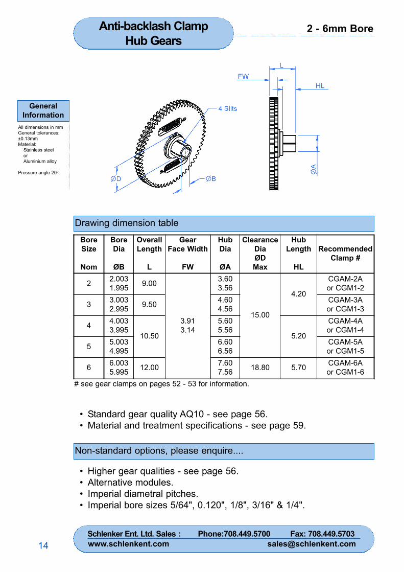
2 - 6mm BoreAnti-backlash ClampHub Gears
GeneralInformation
All dimensions in mmGeneral tolerances:±0.13mmMaterial:
Stainless steelorAluminium alloy
Pressure angle 20º
14
Drawing dimension table
Non-standard options, please enquire....
• Standard gear quality AQ10 - see page 56.• Material and treatment specifications - see page 59.
• Higher gear qualities - see page 56.• Alternative modules.• Imperial diametral pitches.• Imperial bore sizes 5/64", 0.120", 1/8", 3/16" & 1/4".
BoreSize
Nom
BoreDia
ØB
OverallLength
L
GearFace Width
FW
HubDia
ØA
ClearanceDiaØDMax
HubLength
HL
RecommendedClamp #
2 2.0031.995 9.00
3.913.14
3.603.56
15.00
4.20
CGAM-2Aor CGM1-2
3 3.0032.995 9.50 4.60
4.56CGAM-3Aor CGM1-3
4 4.0033.995
10.50
5.605.56
5.20
CGAM-4Aor CGM1-4
5 5.0034.995
6.606.56
CGAM-5Aor CGM1-5
6 6.0035.995 12.00 7.60
7.56 18.80 5.70 CGAM-6Aor CGM1-6
# see gear clamps on pages 52 - 53 for information.
Schlenker Ent. Ltd. Sales : Phone:708.449.5700 Fax: 708.449.5703www.schlenkent.com [email protected]
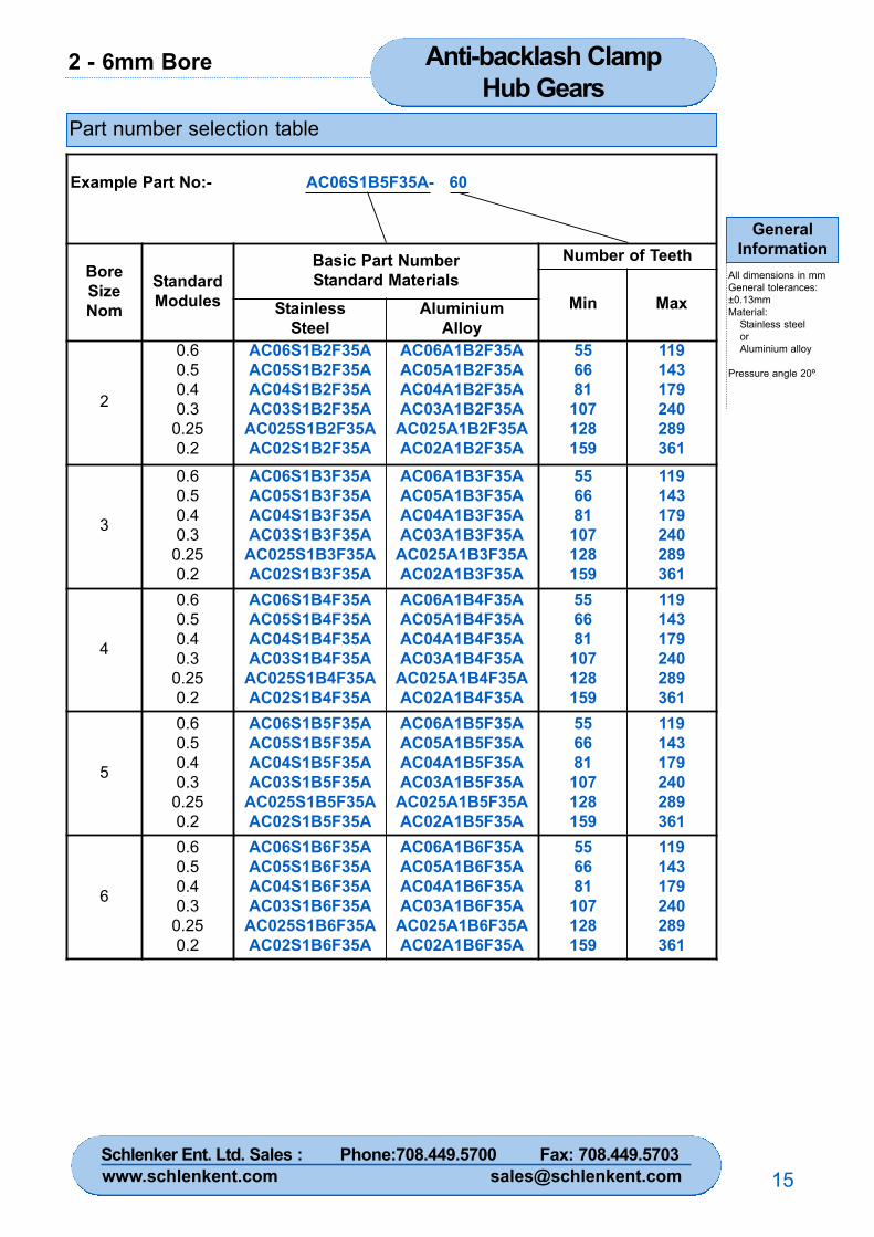
2 - 6mm Bore Anti-backlash ClampHub Gears
GeneralInformation
All dimensions in mmGeneral tolerances:±0.13mmMaterial:
Stainless steelorAluminium alloy
Pressure angle 20º
15
Part number selection table
Example Part No:- AC06S1B5F35A- 60
BoreSizeNom
StandardModules
Basic Part NumberStandard Materials
Number of Teeth
Min MaxStainlessSteel
AluminiumAlloy
2
0.60.50.40.3
0.250.2
AC06S1B2F35AAC05S1B2F35AAC04S1B2F35AAC03S1B2F35A
AC025S1B2F35AAC02S1B2F35A
AC06A1B2F35AAC05A1B2F35AAC04A1B2F35AAC03A1B2F35A
AC025A1B2F35AAC02A1B2F35A
556681
107128159
119143179240289361
3
0.60.50.40.3
0.250.2
AC06S1B3F35AAC05S1B3F35AAC04S1B3F35AAC03S1B3F35A
AC025S1B3F35AAC02S1B3F35A
AC06A1B3F35AAC05A1B3F35AAC04A1B3F35AAC03A1B3F35A
AC025A1B3F35AAC02A1B3F35A
556681
107128159
119143179240289361
4
0.60.50.40.3
0.250.2
AC06S1B4F35AAC05S1B4F35AAC04S1B4F35AAC03S1B4F35A
AC025S1B4F35AAC02S1B4F35A
AC06A1B4F35AAC05A1B4F35AAC04A1B4F35AAC03A1B4F35A
AC025A1B4F35AAC02A1B4F35A
556681
107128159
119143179240289361
5
0.60.50.40.3
0.250.2
AC06S1B5F35AAC05S1B5F35AAC04S1B5F35AAC03S1B5F35A
AC025S1B5F35AAC02S1B5F35A
AC06A1B5F35AAC05A1B5F35AAC04A1B5F35AAC03A1B5F35A
AC025A1B5F35AAC02A1B5F35A
556681
107128159
119143179240289361
6
0.60.50.40.3
0.250.2
AC06S1B6F35AAC05S1B6F35AAC04S1B6F35AAC03S1B6F35A
AC025S1B6F35AAC02S1B6F35A
AC06A1B6F35AAC05A1B6F35AAC04A1B6F35AAC03A1B6F35A
AC025A1B6F35AAC02A1B6F35A
556681
107128159
119143179240289361
Schlenker Ent. Ltd. Sales : Phone:708.449.5700 Fax: 708.449.5703www.schlenkent.com [email protected]
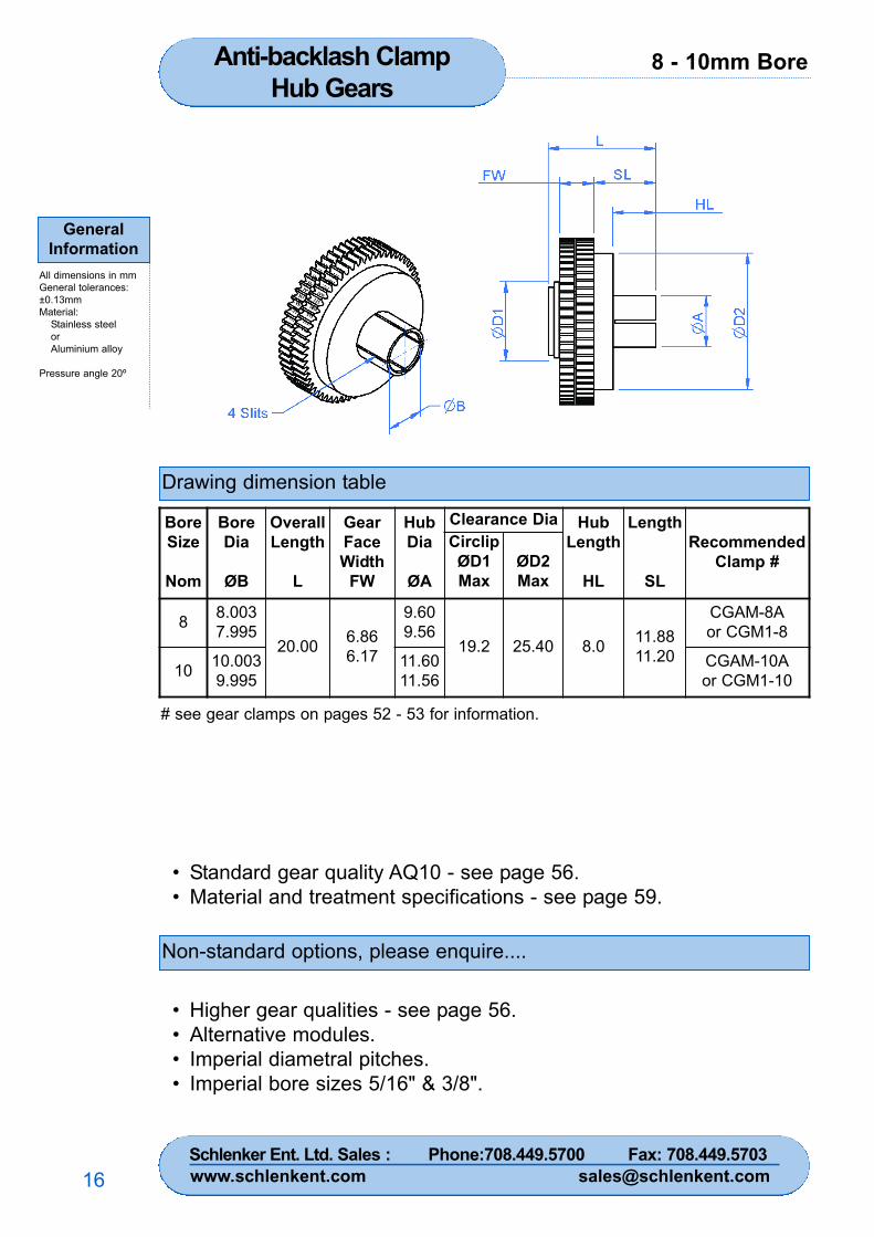
8 - 10mm BoreAnti-backlash ClampHub Gears
GeneralInformation
All dimensions in mmGeneral tolerances:±0.13mmMaterial:
Stainless steelorAluminium alloy
Pressure angle 20º
16
Drawing dimension table
Non-standard options, please enquire....
• Standard gear quality AQ10 - see page 56.• Material and treatment specifications - see page 59.
• Higher gear qualities - see page 56.• Alternative modules.• Imperial diametral pitches.• Imperial bore sizes 5/16" & 3/8".
# see gear clamps on pages 52 - 53 for information.
BoreSize
Nom
BoreDia
ØB
OverallLength
L
GearFaceWidth
FW
HubDia
ØA
Clearance Dia HubLength
HL
Length
SL
RecommendedClamp #
CirclipØD1Max
ØD2Max
8 8.0037.995
20.00 6.866.17
9.609.56
19.2 25.40 8.0 11.8811.20
CGAM-8Aor CGM1-8
10 10.0039.995
11.6011.56
CGAM-10Aor CGM1-10
Schlenker Ent. Ltd. Sales : Phone:708.449.5700 Fax: 708.449.5703www.schlenkent.com [email protected]
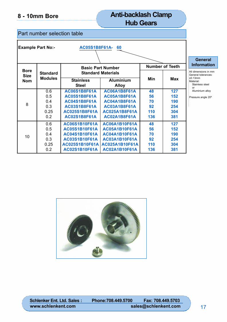
8 - 10mm Bore Anti-backlash ClampHub Gears
GeneralInformation
All dimensions in mmGeneral tolerances:±0.13mmMaterial:
Stainless steelorAluminium alloy
Pressure angle 20º
17
Part number selection table
Example Part No:- AC05S1B8F61A- 60
BoreSizeNom
StandardModules
Basic Part NumberStandard Materials
Number of Teeth
Min MaxStainlessSteel
AluminiumAlloy
8
0.60.50.40.3
0.250.2
AC06S1B8F61AAC05S1B8F61AAC04S1B8F61AAC03S1B8F61A
AC025S1B8F61AAC02S1B8F61A
AC06A1B8F61AAC05A1B8F61AAC04A1B8F61AAC03A1B8F61A
AC025A1B8F61AAC02A1B8F61A
48567092110136
127152190254304381
10
0.60.50.40.3
0.250.2
AC06S1B10F61AAC05S1B10F61AAC04S1B10F61AAC03S1B10F61A
AC025S1B10F61AAC02S1B10F61A
AC06A1B10F61AAC05A1B10F61AAC04A1B10F61AAC03A1B10F61A
AC025A1B10F61AAC02A1B10F61A
48567092110136
127152190254304381
Schlenker Ent. Ltd. Sales : Phone:708.449.5700 Fax: 708.449.5703www.schlenkent.com [email protected]
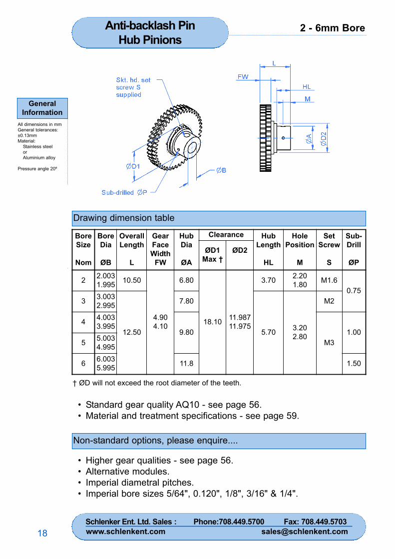
2 - 6mm BoreAnti-backlash PinHub Pinions
GeneralInformation
All dimensions in mmGeneral tolerances:±0.13mmMaterial:
Stainless steelorAluminium alloy
Pressure angle 20º
18
Drawing dimension table
Non-standard options, please enquire....
• Standard gear quality AQ10 - see page 56.• Material and treatment specifications - see page 59.
• Higher gear qualities - see page 56.• Alternative modules.• Imperial diametral pitches.• Imperial bore sizes 5/64", 0.120", 1/8", 3/16" & 1/4".
† ØD will not exceed the root diameter of the teeth.
BoreSize
Nom
BoreDia
ØB
OverallLength
L
GearFaceWidth
FW
HubDia
ØA
Clearance HubLength
HL
HolePosition
M
SetScrew
S
Sub-Drill
ØPØD1
Max †ØD2
2 2.0031.995 10.50
4.904.10
6.80
18.10 11.98711.975
3.70 2.201.80 M1.6
0.753 3.003
2.995
12.50
7.80
5.70 3.202.80
M2
4 4.0033.995
9.80M3
1.005 5.003
4.995
6 6.0035.995 11.8 1.50
Schlenker Ent. Ltd. Sales : Phone:708.449.5700 Fax: 708.449.5703www.schlenkent.com [email protected]

2 - 6mm Bore Anti-backlash PinHub Pinions
GeneralInformation
All dimensions in mmGeneral tolerances:±0.13mmMaterial:
Stainless steelorAluminium alloy
Pressure angle 20º
19
Part number selection table
Example Part No:- AP06S1B5F45A- 44
BoreSizeNom
StandardModules
Basic Part NumberStandard Materials
Number of Teeth
Min MaxStainlessSteel
AluminiumAlloy
2
0.60.50.40.3
0.250.2
AP06S1B2F45AAP05S1B2F45AAP04S1B2F45AAP03S1B2F45A
AP025S1B2F45AAP02S1B2F45A
AP06A1B2F45AAP05A1B2F45AAP04A1B2F45AAP03A1B2F45A
AP025A1B2F45AAP02A1B2F45A
293442556580
597290
121146183
3
0.60.50.40.3
0.250.2
AP06S1B3F45AAP05S1B3F45AAP04S1B3F45AAP03S1B3F45A
AP025S1B3F45AAP02S1B3F45A
AP06A1B3F45AAP05A1B3F45AAP04A1B3F45AAP03A1B3F45A
AP025A1B3F45AAP02A1B3F45A
293442556580
597290
121146183
4
0.60.50.40.3
0.250.2
AP06S1B4F45AAP05S1B4F45AAP04S1B4F45AAP03S1B4F45A
AP025S1B4F45AAP02S1B4F45A
AP06A1B4F45AAP05A1B4F45AAP04A1B4F45AAP03A1B4F45A
AP025A1B4F45AAP02A1B4F45A
293442556580
597290
121146183
5
0.60.50.40.3
0.250.2
AP06S1B5F45AAP05S1B5F45AAP04S1B5F45AAP03S1B5F45A
AP025S1B5F45AAP02S1B5F45A
AP06A1B5F45AAP05A1B5F45AAP04A1B5F45AAP03A1B5F45A
AP025A1B5F45AAP02A1B5F45A
293442556580
597290
121146183
6
0.60.50.40.3
0.250.2
AP06S1B6F45AAP05S1B6F45AAP04S1B6F45AAP03S1B6F45A
AP025S1B6F45AAP02S1B6F45A
AP06A1B6F45AAP05A1B6F45AAP04A1B6F45AAP03A1B6F45A
AP025A1B6F45AAP02A1B6F45A
293442556580
597290
121146183
Schlenker Ent. Ltd. Sales : Phone:708.449.5700 Fax: 708.449.5703www.schlenkent.com [email protected]
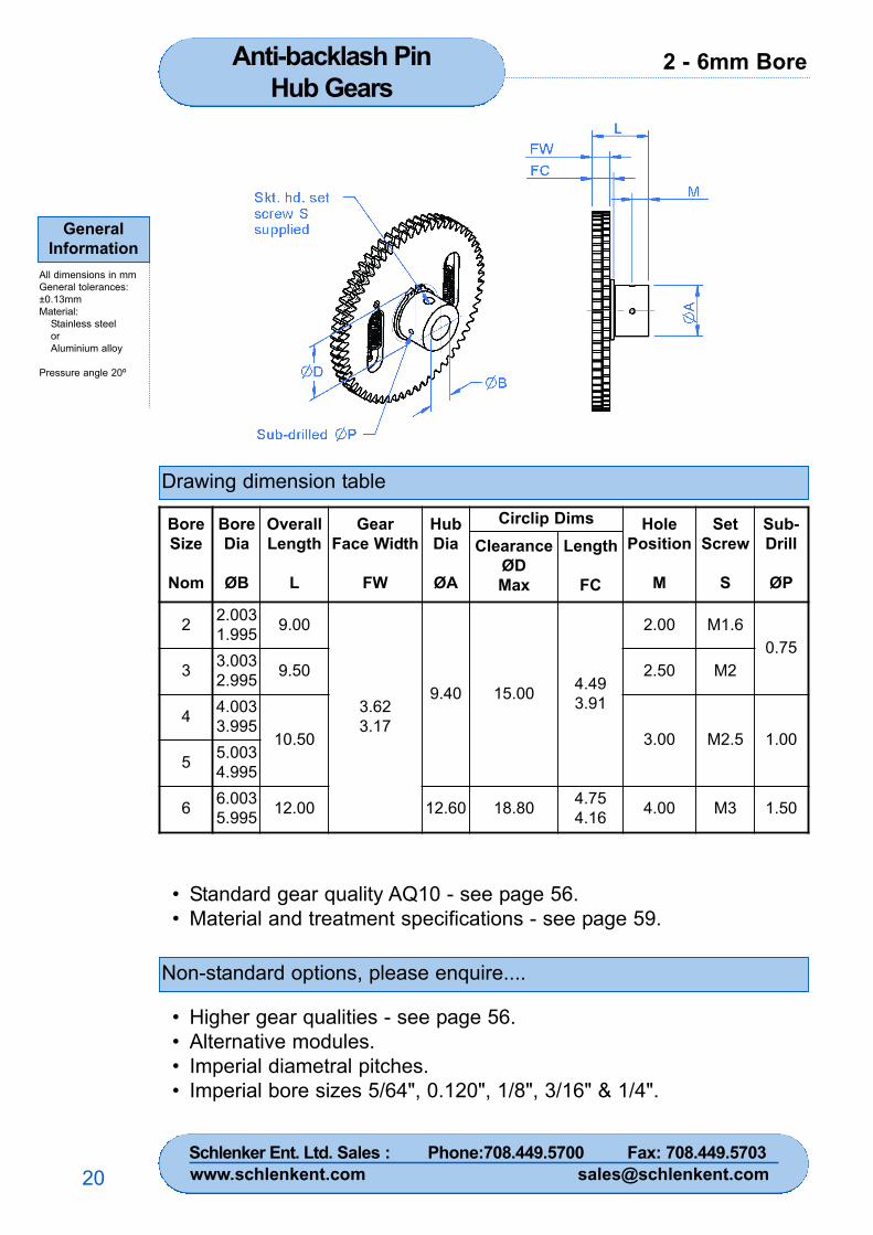
2 - 6mm BoreAnti-backlash PinHub Gears
GeneralInformation
All dimensions in mmGeneral tolerances:±0.13mmMaterial:
Stainless steelorAluminium alloy
Pressure angle 20º
20
Drawing dimension table
Non-standard options, please enquire....
• Standard gear quality AQ10 - see page 56.• Material and treatment specifications - see page 59.
• Higher gear qualities - see page 56.• Alternative modules.• Imperial diametral pitches.• Imperial bore sizes 5/64", 0.120", 1/8", 3/16" & 1/4".
BoreSize
Nom
BoreDia
ØB
OverallLength
L
GearFace Width
FW
HubDia
ØA
Circlip Dims HolePosition
M
SetScrew
S
Sub-Drill
ØP
ClearanceØDMax
Length
FC
2 2.0031.995 9.00
3.623.17
9.40 15.00 4.493.91
2.00 M1.60.75
3 3.0032.995 9.50 2.50 M2
4 4.0033.995
10.50 3.00 M2.5 1.005 5.003
4.995
6 6.0035.995 12.00 12.60 18.80 4.75
4.16 4.00 M3 1.50
Schlenker Ent. Ltd. Sales : Phone:708.449.5700 Fax: 708.449.5703www.schlenkent.com [email protected]
2 - 6mm Bore Anti-backlash PinHub Gears
GeneralInformation
All dimensions in mmGeneral tolerances:±0.13mmMaterial:
Stainless steelorAluminium alloy
Pressure angle 20º
21
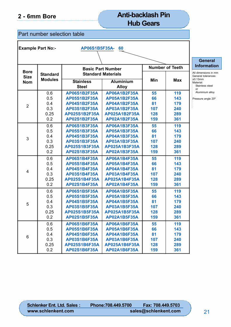
Part number selection table
Example Part No:- AP06S1B5F35A- 60
BoreSizeNom
StandardModules
Basic Part NumberStandard Materials
Number of Teeth
Min MaxStainlessSteel
AluminiumAlloy
2
0.60.50.40.3
0.250.2
AP06S1B2F35AAP05S1B2F35AAP04S1B2F35AAP03S1B2F35A
AP025S1B2F35AAP02S1B2F35A
AP06A1B2F35AAP05A1B2F35AAP04A1B2F35AAP03A1B2F35A
AP025A1B2F35AAP02A1B2F35A
556681
107128159
119143179240289361
3
0.60.50.40.3
0.250.2
AP06S1B3F35AAP05S1B3F35AAP04S1B3F35AAP03S1B3F35A
AP025S1B3F35AAP02S1B3F35A
AP06A1B3F35AAP05A1B3F35AAP04A1B3F35AAP03A1B3F35A
AP025A1B3F35AAP02A1B3F35A
556681
107128159
119143179240289361
4
0.60.50.40.3
0.250.2
AP06S1B4F35AAP05S1B4F35AAP04S1B4F35AAP03S1B4F35A
AP025S1B4F35AAP02S1B4F35A
AP06A1B4F35AAP05A1B4F35AAP04A1B4F35AAP03A1B4F35A
AP025A1B4F35AAP02A1B4F35A
556681
107128159
119143179240289361
5
0.60.50.40.3
0.250.2
AP06S1B5F35AAP05S1B5F35AAP04S1B5F35AAP03S1B5F35A
AP025S1B5F35AAP02S1B5F35A
AP06A1B5F35AAP05A1B5F35AAP04A1B5F35AAP03A1B5F35A
AP025A1B5F35AAP02A1B5F35A
556681
107128159
119143179240289361
6
0.60.50.40.3
0.250.2
AP06S1B6F35AAP05S1B6F35AAP04S1B6F35AAP03S1B6F35A
AP025S1B6F35AAP02S1B6F35A
AP06A1B6F35AAP05A1B6F35AAP04A1B6F35AAP03A1B6F35A
AP025A1B6F35AAP02A1B6F35A
556681
107128159
119143179240289361
Schlenker Ent. Ltd. Sales : Phone:708.449.5700 Fax: 708.449.5703www.schlenkent.com [email protected]
8 - 10mm BoreAnti-backlash Pin Hub Gears
GeneralInformation
All dimensions in mmGeneral tolerances:±0.13mmMaterial:
Stainless steelorAluminium alloy
Pressure angle 20º
22
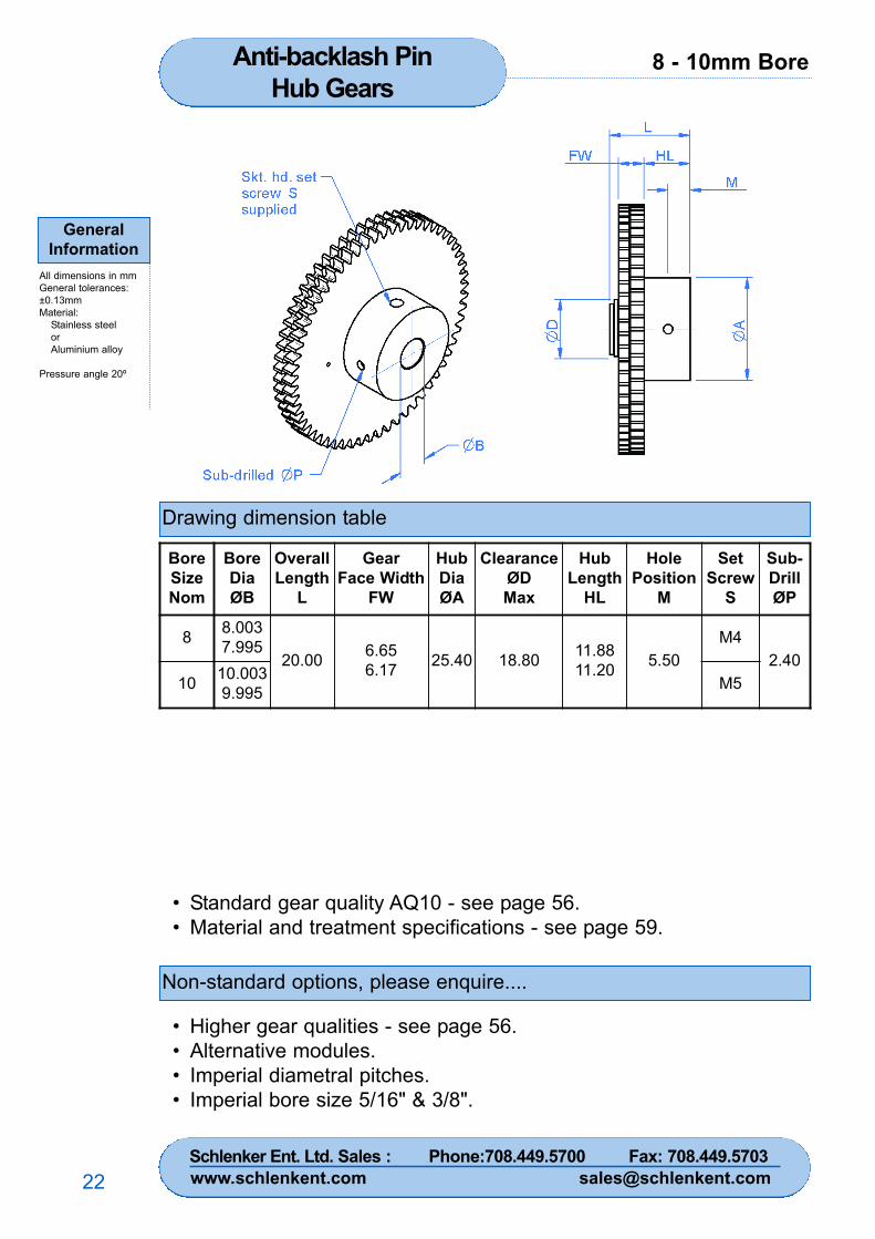
Drawing dimension table
Non-standard options, please enquire....
• Standard gear quality AQ10 - see page 56.• Material and treatment specifications - see page 59.
• Higher gear qualities - see page 56.• Alternative modules.• Imperial diametral pitches.• Imperial bore size 5/16" & 3/8".
BoreSizeNom
BoreDiaØB
OverallLength
L
GearFace Width
FW
HubDiaØA
ClearanceØDMax
HubLength
HL
HolePosition
M
SetScrew
S
Sub-DrillØP
8 8.0037.995
20.00 6.656.17 25.40 18.80 11.88
11.20 5.50M4
2.4010 10.003
9.995 M5
Schlenker Ent. Ltd. Sales : Phone:708.449.5700 Fax: 708.449.5703www.schlenkent.com [email protected]
8 - 10mm Bore Anti-backlash PinHub Gears
GeneralInformation
All dimensions in mmGeneral tolerances:±0.13mmMaterial:
Stainless steelorAluminium alloy
Pressure angle 20º
23
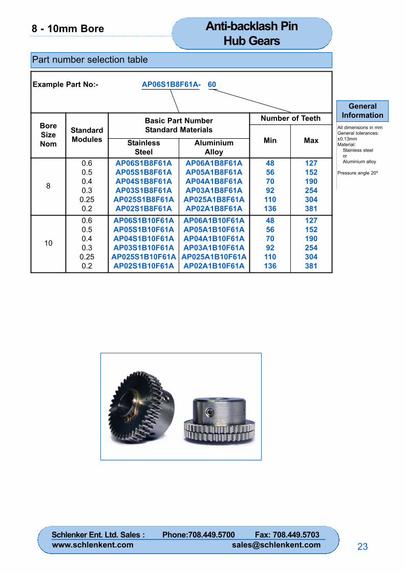
Part number selection table
Example Part No:- AP06S1B8F61A- 60
BoreSizeNom
StandardModules
Basic Part NumberStandard Materials
Number of Teeth
Min MaxStainlessSteel
AluminiumAlloy
8
0.60.50.40.3
0.250.2
AP06S1B8F61AAP05S1B8F61AAP04S1B8F61AAP03S1B8F61A
AP025S1B8F61AAP02S1B8F61A
AP06A1B8F61AAP05A1B8F61AAP04A1B8F61AAP03A1B8F61A
AP025A1B8F61AAP02A1B8F61A
48567092110136
127152190254304381
10
0.60.50.40.3
0.250.2
AP06S1B10F61AAP05S1B10F61AAP04S1B10F61AAP03S1B10F61A
AP025S1B10F61AAP02S1B10F61A
AP06A1B10F61AAP05A1B10F61AAP04A1B10F61AAP03A1B10F61A
AP025A1B10F61AAP02A1B10F61A
48567092110136
127152190254304381
Schlenker Ent. Ltd. Sales : Phone:708.449.5700 Fax: 708.449.5703www.schlenkent.com [email protected]

3 - 5mm BoreReli-a-Grip™Clamp Hub Gears
GeneralInformation
All dimensions in mmGeneral tolerances:±0.13mmMaterial:
Stainless steelorAluminium alloy
Pressure angle 20º
24
Drawing dimension table
Non-standard options, please enquire....
• Standard gear quality AQ10 - see page 56.• Material and treatment specifications - see page 59.
• Higher gear qualities - see page 56.• Alternative modules.• Imperial diametral pitches.• Imperial bore sizes 1/8", 3/16" & 1/4".
BoreSizeNom
BoreDiaØB
OverallLength
L
GearFace Width
FW
Reli-a-Grip™DiaØA
HolePosition
M
ScrewSupplied
S
3 3.0032.995
8 2
13.00 2.50 M1.6
10 4
4 4.0033.995
8 210 4
5 5.0034.995
8 210 4
Schlenker Ent. Ltd. Sales : Phone:708.449.5700 Fax: 708.449.5703www.schlenkent.com [email protected]
3 - 5mm Bore Reli-a-Grip™Clamp Hub Gears
GeneralInformation
All dimensions in mmGeneral tolerances:±0.13mmMaterial:
Stainless steelorAluminium alloy
Pressure angle 20º
25
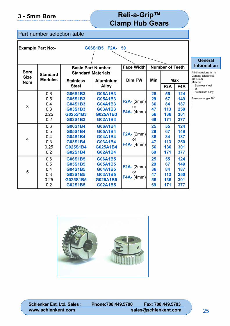
Part number selection table
Example Part No:- G06S1B5 F2A- 50
BoreSizeNom
StandardModules
Basic Part NumberStandard Materials
Face Width Number of Teeth
Dim FW Min MaxStainlessSteel
AluminiumAlloy F2A F4A
3
0.60.50.40.3
0.250.2
G06S1B3G05S1B3G04S1B3G03S1B3
G025S1B3G02S1B3
G06A1B3G05A1B3G04A1B3G03A1B3
G025A1B3G02A1B3
F2A- (2mm)or
F4A- (4mm)
252936475669
556784113136171
124149187250301377
4
0.60.50.40.3
0.250.2
G06S1B4G05S1B4G04S1B4G03S1B4
G025S1B4G02S1B4
G06A1B4G05A1B4G04A1B4G03A1B4
G025A1B4G02A1B4
F2A- (2mm)or
F4A- (4mm)
252936475669
556784113136171
124149187250301377
5
0.60.50.40.3
0.250.2
G06S1B5G05S1B5G04S1B5G03S1B5
G025S1B5G02S1B5
G06A1B5G05A1B5G04A1B5G03A1B5
G025A1B5G02A1B5
F2A- (2mm)or
F4A- (4mm)
252936475669
556784113136171
124149187250301377
Schlenker Ent. Ltd. Sales : Phone:708.449.5700 Fax: 708.449.5703www.schlenkent.com [email protected]
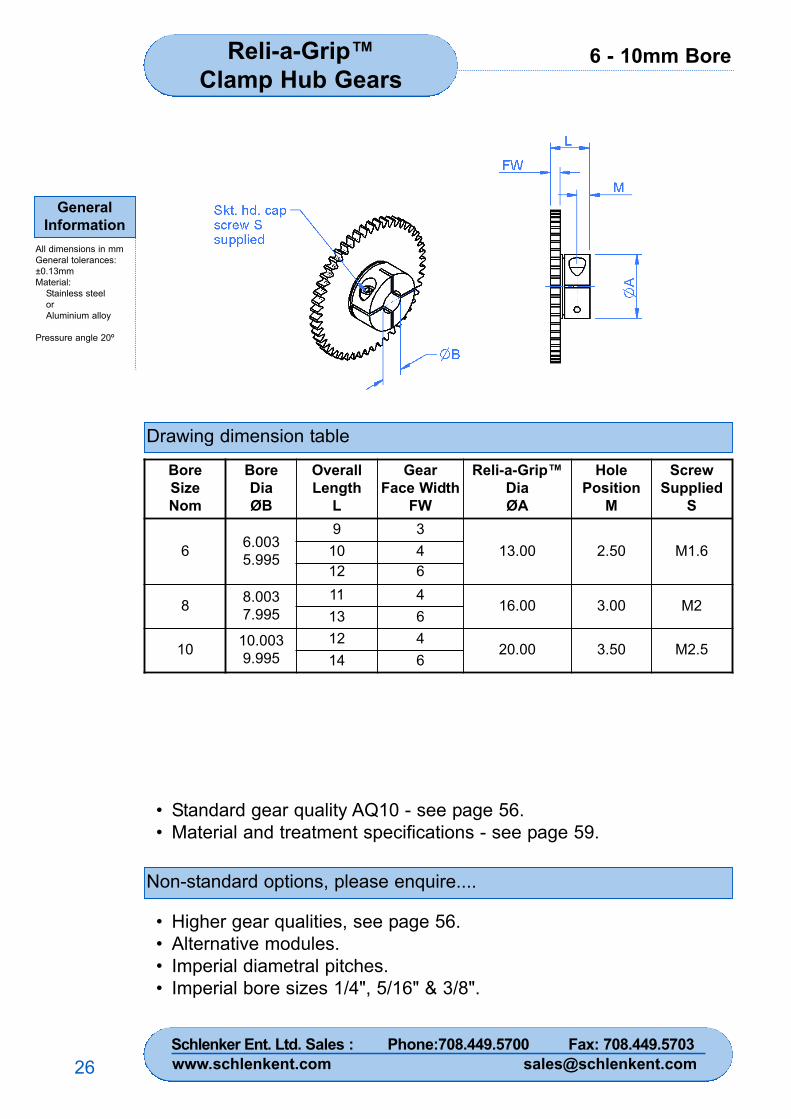
6 - 10mm BoreReli-a-Grip™Clamp Hub Gears
GeneralInformation
All dimensions in mmGeneral tolerances:±0.13mmMaterial:
Stainless steelorAluminium alloy
Pressure angle 20º
26
Drawing dimension table
Non-standard options, please enquire....
• Standard gear quality AQ10 - see page 56.• Material and treatment specifications - see page 59.
• Higher gear qualities, see page 56.• Alternative modules.• Imperial diametral pitches.• Imperial bore sizes 1/4", 5/16" & 3/8".
BoreSizeNom
BoreDiaØB
OverallLength
L
GearFace Width
FW
Reli-a-Grip™DiaØA
HolePosition
M
ScrewSupplied
S
6 6.0035.995
9 313.00 2.50 M1.610 4
12 6
8 8.0037.995
11 416.00 3.00 M2
13 6
10 10.0039.995
12 420.00 3.50 M2.5
14 6
Schlenker Ent. Ltd. Sales : Phone:708.449.5700 Fax: 708.449.5703www.schlenkent.com [email protected]
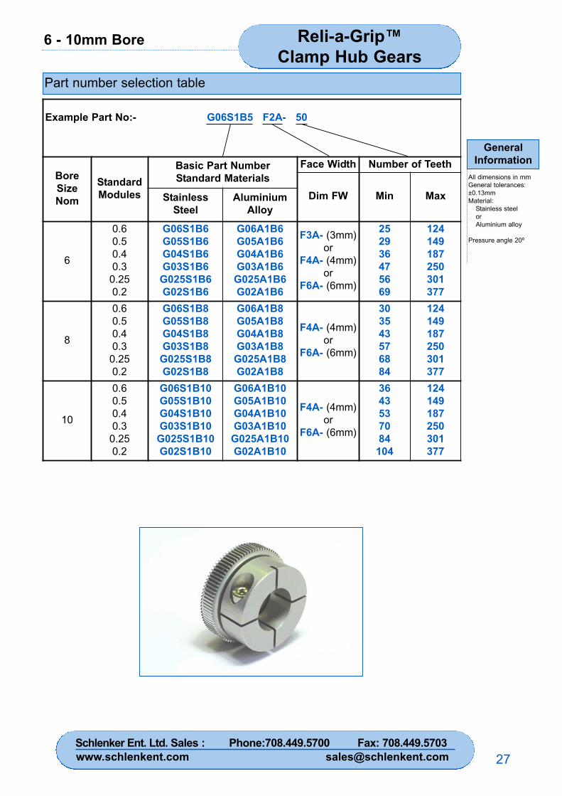
6 - 10mm Bore Reli-a-Grip™Clamp Hub Gears
GeneralInformation
All dimensions in mmGeneral tolerances:±0.13mmMaterial:
Stainless steelorAluminium alloy
Pressure angle 20º
27
Part number selection table
Example Part No:- G06S1B5 F2A- 50
BoreSizeNom
StandardModules
Basic Part NumberStandard Materials
Face Width Number of Teeth
Dim FW Min MaxStainlessSteel
AluminiumAlloy
6
0.60.50.40.3
0.250.2
G06S1B6G05S1B6G04S1B6G03S1B6
G025S1B6G02S1B6
G06A1B6G05A1B6G04A1B6G03A1B6
G025A1B6G02A1B6
F3A- (3mm)or
F4A- (4mm)or
F6A- (6mm)
252936475669
124149187250301377
8
0.60.50.40.3
0.250.2
G06S1B8G05S1B8G04S1B8G03S1B8
G025S1B8G02S1B8
G06A1B8G05A1B8G04A1B8G03A1B8
G025A1B8G02A1B8
F4A- (4mm)or
F6A- (6mm)
303543576884
124149187250301377
10
0.60.50.40.3
0.250.2
G06S1B10G05S1B10G04S1B10G03S1B10
G025S1B10G02S1B10
G06A1B10G05A1B10G04A1B10G03A1B10
G025A1B10G02A1B10
F4A- (4mm)or
F6A- (6mm)
3643537084
104
124149187250301377
Schlenker Ent. Ltd. Sales : Phone:708.449.5700 Fax: 708.449.5703www.schlenkent.com [email protected]
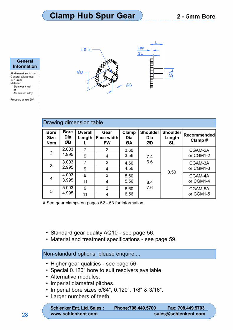
2 - 5mm BoreClamp Hub Spur Gear
GeneralInformation
All dimensions in mmGeneral tolerances:±0.13mmMaterial:
Stainless steelorAluminium alloy
Pressure angle 20º
28
Drawing dimension table
Non-standard options, please enquire....
• Standard gear quality AQ10 - see page 56.• Material and treatment specifications - see page 59.
• Higher gear qualities - see page 56.• Special 0.120" bore to suit resolvers available.• Alternative modules.• Imperial diametral pitches.• Imperial bore sizes 5/64", 0.120", 1/8" & 3/16".• Larger numbers of teeth.
BoreSizeNom
BoreDiaØB
OverallLength
L
GearFace width
FW
ClampDiaØA
ShoulderDiaØD
ShoulderLength
SL
RecommendedClamp #
22.0031.995
7 2 3.603.56 7.4
6.6
0.50
CGAM-2Aor CGM1-29 4
33.0032.995
7 2 4.604.56
CGAM-3Aor CGM1-39 4
44.0033.995
9 2 5.605.56 8.4
7.6
CGAM-4Aor CGM1-411 4
55.0034.995
9 2 6.606.56
CGAM-5Aor CGM1-511 4
# See gear clamps on pages 52 - 53 for information.
Schlenker Ent. Ltd. Sales : Phone:708.449.5700 Fax: 708.449.5703www.schlenkent.com [email protected]
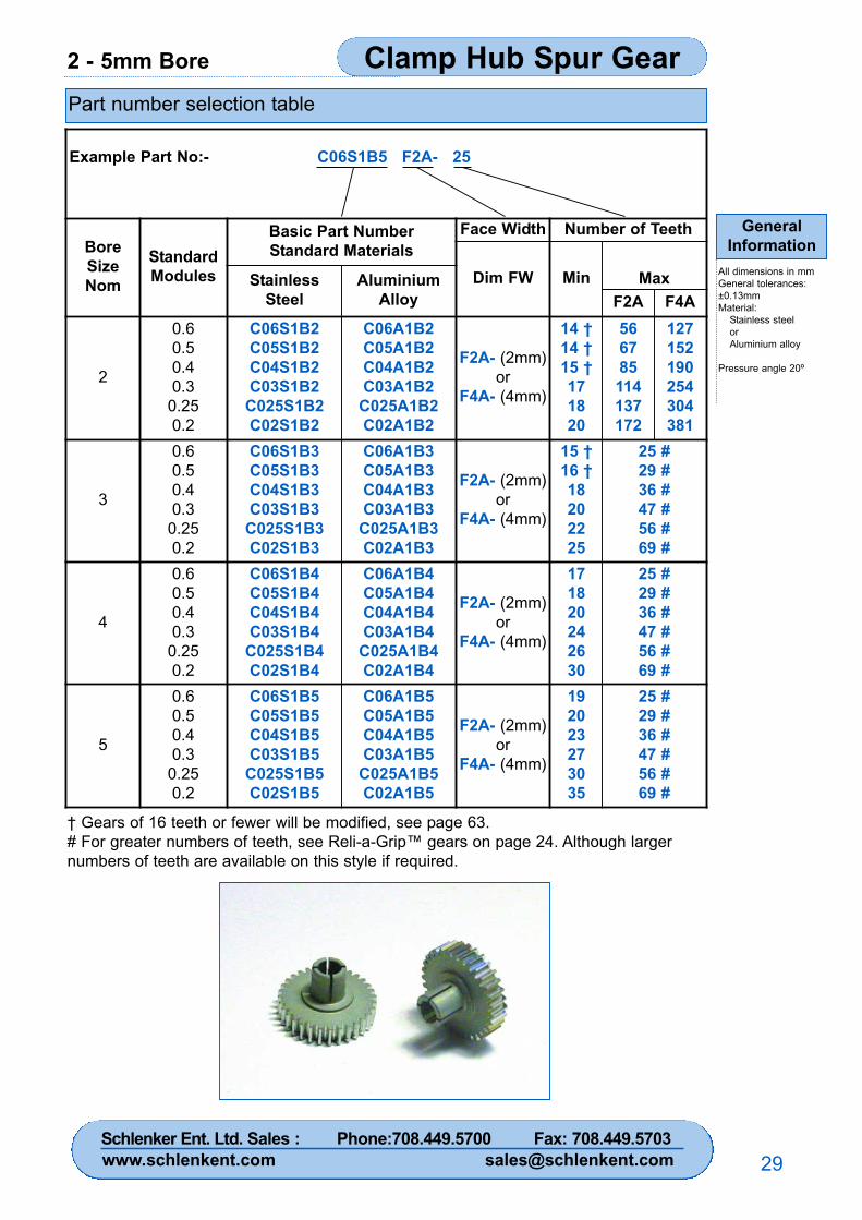
2 - 5mm Bore Clamp Hub Spur Gear
GeneralInformation
All dimensions in mmGeneral tolerances:±0.13mmMaterial:
Stainless steelorAluminium alloy
Pressure angle 20º
29
Part number selection table
† Gears of 16 teeth or fewer will be modified, see page 63.# For greater numbers of teeth, see Reli-a-Grip™ gears on page 24. Although largernumbers of teeth are available on this style if required.
Example Part No:- C06S1B5 F2A- 25
BoreSizeNom
StandardModules
Basic Part NumberStandard Materials
Face Width Number of Teeth
Dim FW Min MaxStainlessSteel
AluminiumAlloy F2A F4A
2
0.60.50.40.3
0.250.2
C06S1B2C05S1B2C04S1B2C03S1B2
C025S1B2C02S1B2
C06A1B2C05A1B2C04A1B2C03A1B2
C025A1B2C02A1B2
F2A- (2mm)or
F4A- (4mm)
14 †14 †15 †171820
566785114137172
127152190254304381
3
0.60.50.40.3
0.250.2
C06S1B3C05S1B3C04S1B3C03S1B3
C025S1B3C02S1B3
C06A1B3C05A1B3C04A1B3C03A1B3
C025A1B3C02A1B3
F2A- (2mm)or
F4A- (4mm)
15 †16 †18202225
25 #29 #36 #47 #56 #69 #
4
0.60.50.40.3
0.250.2
C06S1B4C05S1B4C04S1B4C03S1B4
C025S1B4C02S1B4
C06A1B4C05A1B4C04A1B4C03A1B4
C025A1B4C02A1B4
F2A- (2mm)or
F4A- (4mm)
171820242630
25 #29 #36 #47 #56 #69 #
5
0.60.50.40.3
0.250.2
C06S1B5C05S1B5C04S1B5C03S1B5
C025S1B5C02S1B5
C06A1B5C05A1B5C04A1B5C03A1B5
C025A1B5C02A1B5
F2A- (2mm)or
F4A- (4mm)
192023273035
25 #29 #36 #47 #56 #69 #
Schlenker Ent. Ltd. Sales : Phone:708.449.5700 Fax: 708.449.5703www.schlenkent.com [email protected]
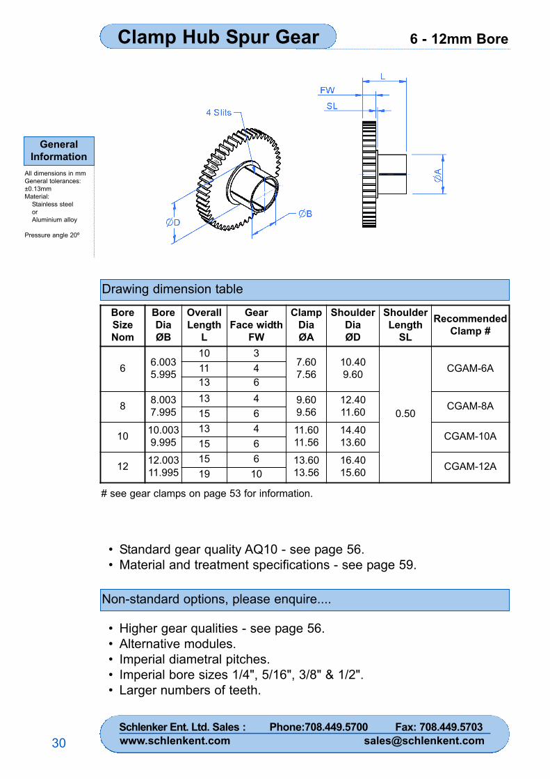
6 - 12mm BoreClamp Hub Spur Gear
GeneralInformation
All dimensions in mmGeneral tolerances:±0.13mmMaterial:
Stainless steelorAluminium alloy
Pressure angle 20º
30
Drawing dimension table
Non-standard options, please enquire....
• Standard gear quality AQ10 - see page 56.• Material and treatment specifications - see page 59.
• Higher gear qualities - see page 56.• Alternative modules.• Imperial diametral pitches.• Imperial bore sizes 1/4", 5/16", 3/8" & 1/2".• Larger numbers of teeth.
BoreSizeNom
BoreDiaØB
OverallLength
L
GearFace width
FW
ClampDiaØA
ShoulderDiaØD
ShoulderLength
SL
RecommendedClamp #
6 6.0035.995
10 37.607.56
10.409.60
0.50
CGAM-6A11 413 6
8 8.0037.995
13 4 9.609.56
12.4011.60 CGAM-8A
15 6
10 10.0039.995
13 4 11.6011.56
14.4013.60 CGAM-10A
15 6
12 12.00311.995
15 6 13.6013.56
16.4015.60 CGAM-12A
19 10
# see gear clamps on page 53 for information.
Schlenker Ent. Ltd. Sales : Phone:708.449.5700 Fax: 708.449.5703www.schlenkent.com [email protected]
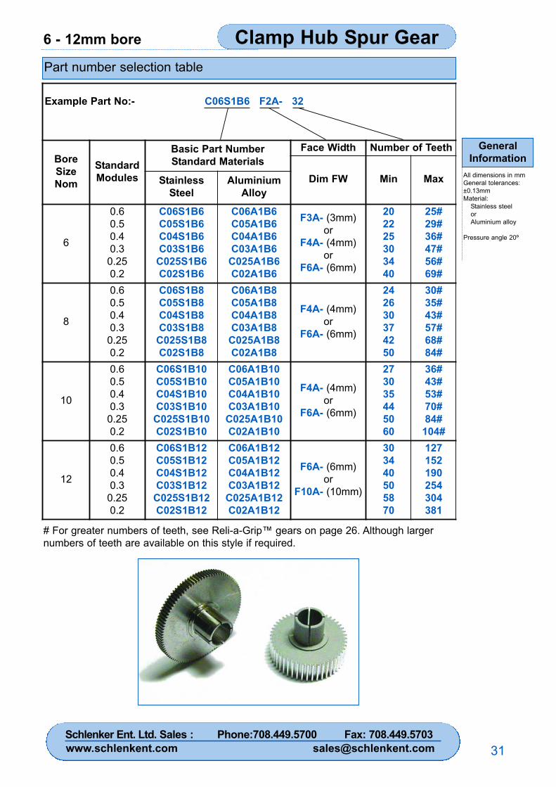
6 - 12mm bore Clamp Hub Spur Gear
GeneralInformation
All dimensions in mmGeneral tolerances:±0.13mmMaterial:
Stainless steelorAluminium alloy
Pressure angle 20º
31
Part number selection table
Example Part No:- C06S1B6 F2A- 32
BoreSizeNom
StandardModules
Basic Part NumberStandard Materials
Face Width Number of Teeth
Dim FW Min MaxStainlessSteel
AluminiumAlloy
6
0.60.50.40.3
0.250.2
C06S1B6C05S1B6C04S1B6C03S1B6
C025S1B6C02S1B6
C06A1B6C05A1B6C04A1B6C03A1B6
C025A1B6C02A1B6
F3A- (3mm)or
F4A- (4mm)or
F6A- (6mm)
202225303440
25#29#36#47#56#69#
8
0.60.50.40.3
0.250.2
C06S1B8C05S1B8C04S1B8C03S1B8
C025S1B8C02S1B8
C06A1B8C05A1B8C04A1B8C03A1B8
C025A1B8C02A1B8
F4A- (4mm)or
F6A- (6mm)
242630374250
30#35#43#57#68#84#
10
0.60.50.40.3
0.250.2
C06S1B10C05S1B10C04S1B10C03S1B10
C025S1B10C02S1B10
C06A1B10C05A1B10C04A1B10C03A1B10
C025A1B10C02A1B10
F4A- (4mm)or
F6A- (6mm)
273035445060
36#43#53#70#84#
104#
12
0.60.50.40.3
0.250.2
C06S1B12C05S1B12C04S1B12C03S1B12
C025S1B12C02S1B12
C06A1B12C05A1B12C04A1B12C03A1B12
C025A1B12C02A1B12
F6A- (6mm)or
F10A- (10mm)
303440505870
127152190254304381
# For greater numbers of teeth, see Reli-a-Grip™ gears on page 26. Although largernumbers of teeth are available on this style if required.
Schlenker Ent. Ltd. Sales : Phone:708.449.5700 Fax: 708.449.5703www.schlenkent.com [email protected]
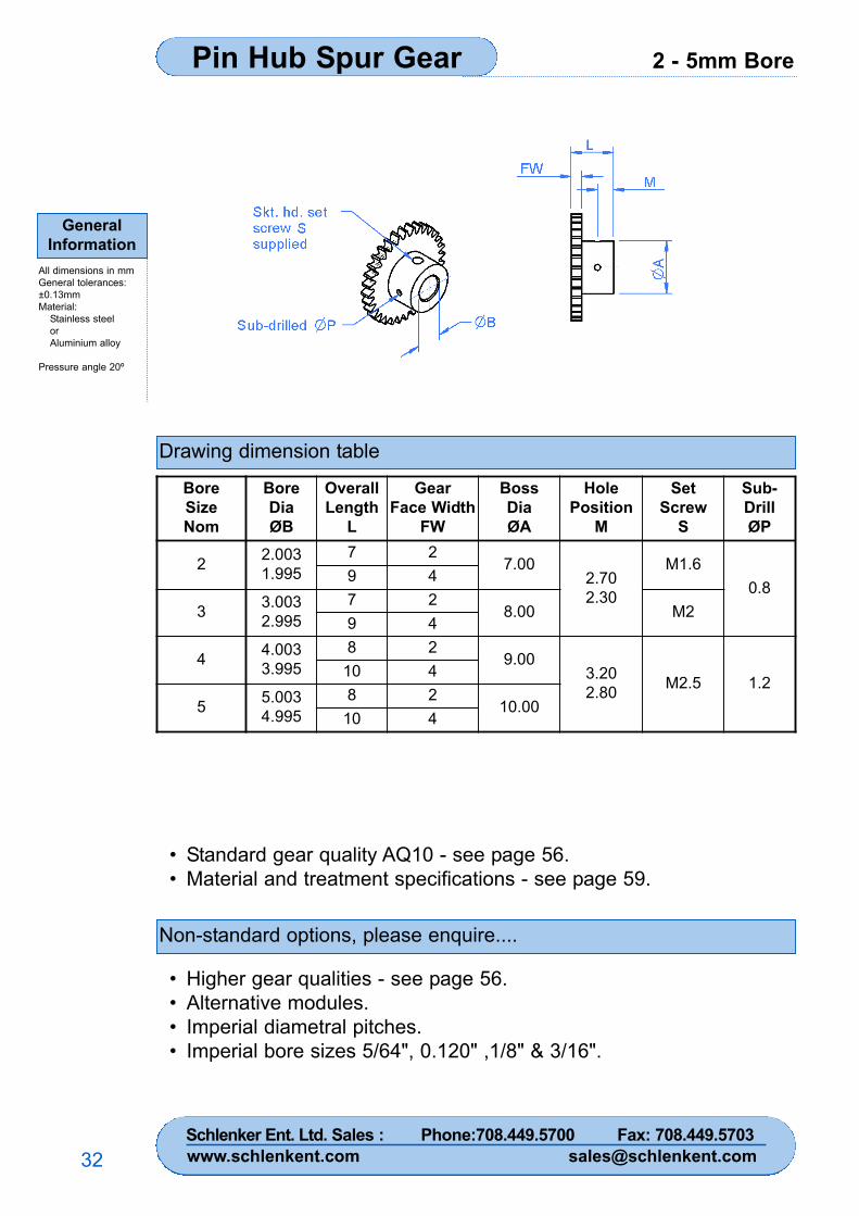
2 - 5mm BorePin Hub Spur Gear
GeneralInformation
All dimensions in mmGeneral tolerances:±0.13mmMaterial:
Stainless steelorAluminium alloy
Pressure angle 20º
32
Drawing dimension table
Non-standard options, please enquire....
• Standard gear quality AQ10 - see page 56.• Material and treatment specifications - see page 59.
• Higher gear qualities - see page 56.• Alternative modules.• Imperial diametral pitches.• Imperial bore sizes 5/64", 0.120" ,1/8" & 3/16".
BoreSizeNom
BoreDiaØB
OverallLength
L
GearFace Width
FW
BossDiaØA
HolePosition
M
SetScrew
S
Sub-DrillØP
2 2.0031.995
7 27.00
2.702.30
M1.60.8
9 4
3 3.0032.995
7 28.00 M2
9 4
4 4.0033.995
8 29.00
3.202.80 M2.5 1.2
10 4
5 5.0034.995
8 210.00
10 4
Schlenker Ent. Ltd. Sales : Phone:708.449.5700 Fax: 708.449.5703www.schlenkent.com [email protected]
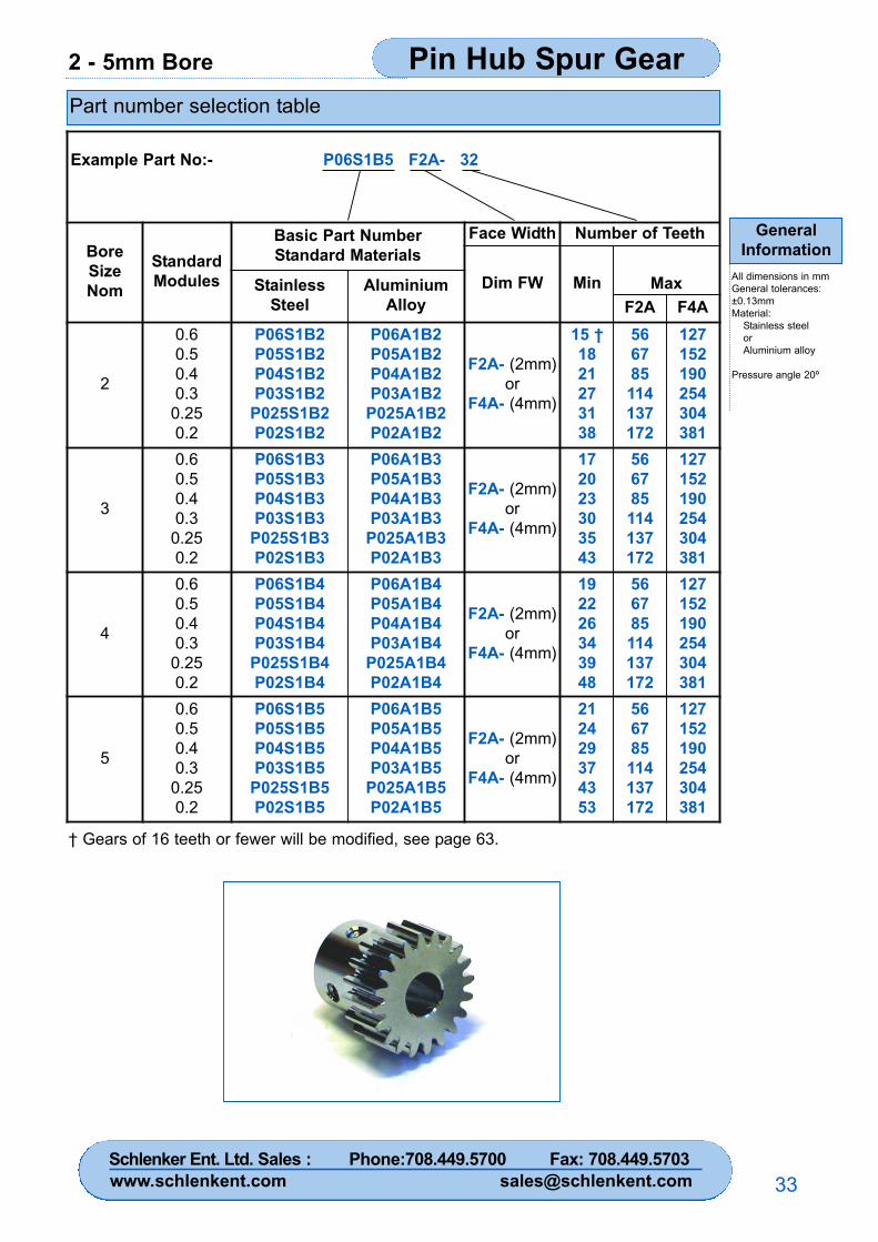
2 - 5mm Bore Pin Hub Spur Gear
GeneralInformation
All dimensions in mmGeneral tolerances:±0.13mmMaterial:
Stainless steelorAluminium alloy
Pressure angle 20º
33
Part number selection table
† Gears of 16 teeth or fewer will be modified, see page 63.
Example Part No:- P06S1B5 F2A- 32
BoreSizeNom
StandardModules
Basic Part NumberStandard Materials
Face Width Number of Teeth
Dim FW Min MaxStainlessSteel
AluminiumAlloy F2A F4A
2
0.60.50.40.3
0.250.2
P06S1B2P05S1B2P04S1B2P03S1B2
P025S1B2P02S1B2
P06A1B2P05A1B2P04A1B2P03A1B2
P025A1B2P02A1B2
F2A- (2mm)or
F4A- (4mm)
15 †1821273138
566785114137172
127152190254304381
3
0.60.50.40.3
0.250.2
P06S1B3P05S1B3P04S1B3P03S1B3
P025S1B3P02S1B3
P06A1B3P05A1B3P04A1B3P03A1B3
P025A1B3P02A1B3
F2A- (2mm)or
F4A- (4mm)
172023303543
566785114137172
127152190254304381
4
0.60.50.40.3
0.250.2
P06S1B4P05S1B4P04S1B4P03S1B4
P025S1B4P02S1B4
P06A1B4P05A1B4P04A1B4P03A1B4
P025A1B4P02A1B4
F2A- (2mm)or
F4A- (4mm)
192226343948
566785114137172
127152190254304381
5
0.60.50.40.3
0.250.2
P06S1B5P05S1B5P04S1B5P03S1B5
P025S1B5P02S1B5
P06A1B5P05A1B5P04A1B5P03A1B5
P025A1B5P02A1B5
F2A- (2mm)or
F4A- (4mm)
212429374353
566785114137172
127152190254304381
Schlenker Ent. Ltd. Sales : Phone:708.449.5700 Fax: 708.449.5703www.schlenkent.com [email protected]
6 - 12mm BorePin Hub Spur Gear
GeneralInformation
All dimensions in mmGeneral tolerances:±0.13mmMaterial:
Stainless steelorAluminium alloy
Pressure angle 20º
34
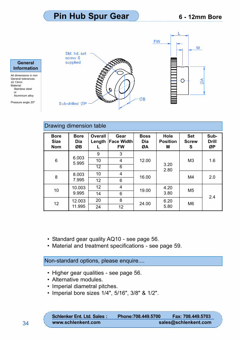
Drawing dimension table
Non-standard options, please enquire....
• Standard gear quality AQ10 - see page 56.• Material and treatment specifications - see page 59.
• Higher gear qualities - see page 56.• Alternative modules.• Imperial diametral pitches.• Imperial bore sizes 1/4", 5/16", 3/8" & 1/2".
BoreSizeNom
BoreDiaØB
OverallLength
L
GearFace Width
FW
BossDiaØA
HolePosition
M
SetScrew
S
Sub-DrillØP
6 6.0035.995
9 312.00
3.202.80
M3 1.610 412 6
8 8.0037.995
10 416.00 M4 2.0
12 6
10 10.0039.995
12 419.00 4.20
3.80 M52.4
14 6
12 12.00311.995
20 824.00 6.20
5.80 M624 12
Schlenker Ent. Ltd. Sales : Phone:708.449.5700 Fax: 708.449.5703www.schlenkent.com [email protected]
6 - 12mm Bore Pin Hub Spur Gear
GeneralInformation
All dimensions in mmGeneral tolerances:±0.13mmMaterial:
Stainless steelorAluminium alloy
Pressure angle 20º
35
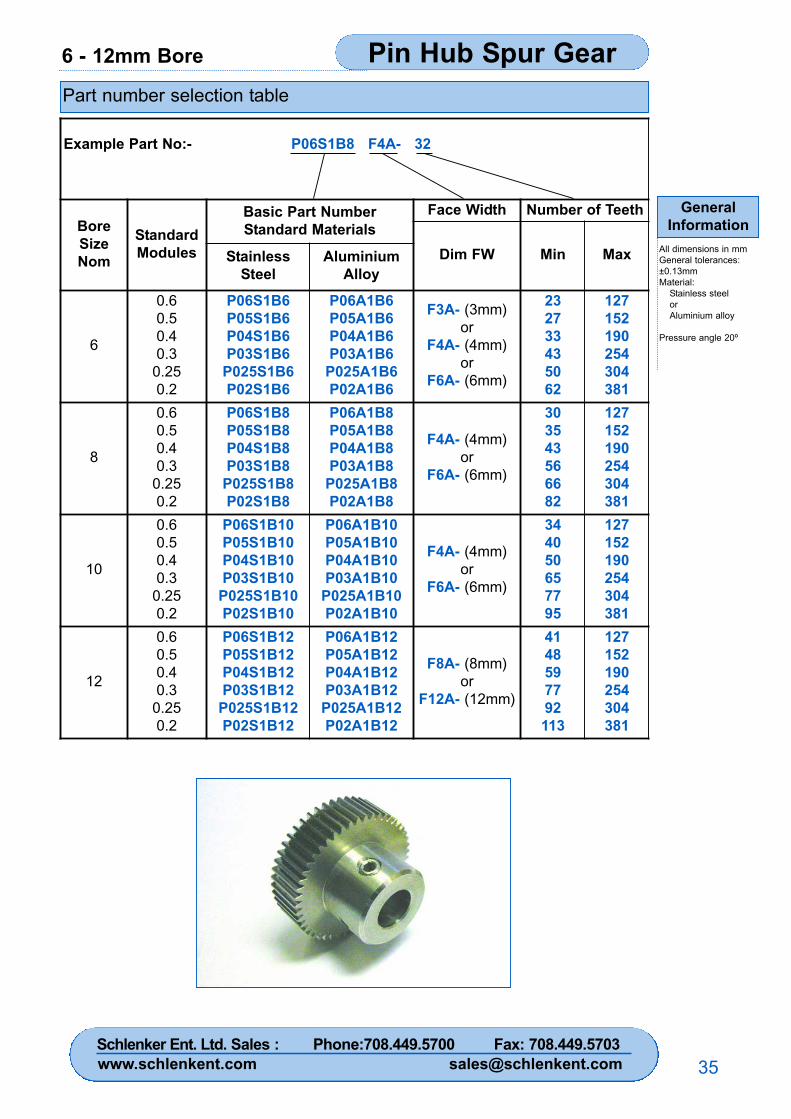
Part number selection table
Example Part No:- P06S1B8 F4A- 32
BoreSizeNom
StandardModules
Basic Part NumberStandard Materials
Face Width Number of Teeth
Dim FW Min MaxStainlessSteel
AluminiumAlloy
6
0.60.50.40.3
0.250.2
P06S1B6P05S1B6P04S1B6P03S1B6
P025S1B6P02S1B6
P06A1B6P05A1B6P04A1B6P03A1B6
P025A1B6P02A1B6
F3A- (3mm)or
F4A- (4mm)or
F6A- (6mm)
232733435062
127152190254304381
8
0.60.50.40.3
0.250.2
P06S1B8P05S1B8P04S1B8P03S1B8
P025S1B8P02S1B8
P06A1B8P05A1B8P04A1B8P03A1B8
P025A1B8P02A1B8
F4A- (4mm)or
F6A- (6mm)
303543566682
127152190254304381
10
0.60.50.40.3
0.250.2
P06S1B10P05S1B10P04S1B10P03S1B10
P025S1B10P02S1B10
P06A1B10P05A1B10P04A1B10P03A1B10
P025A1B10P02A1B10
F4A- (4mm)or
F6A- (6mm)
344050657795
127152190254304381
12
0.60.50.40.3
0.250.2
P06S1B12P05S1B12P04S1B12P03S1B12
P025S1B12P02S1B12
P06A1B12P05A1B12P04A1B12P03A1B12
P025A1B12P02A1B12
F8A- (8mm)or
F12A- (12mm)
4148597792113
127152190254304381
Schlenker Ent. Ltd. Sales : Phone:708.449.5700 Fax: 708.449.5703www.schlenkent.com [email protected]
5 - 25mm BoreHubless Spur Gear
GeneralInformation
All dimensions in mmGeneral tolerances:±0.13mmMaterial:
Stainless steelorAluminium alloy
Pressure angle 20º
36
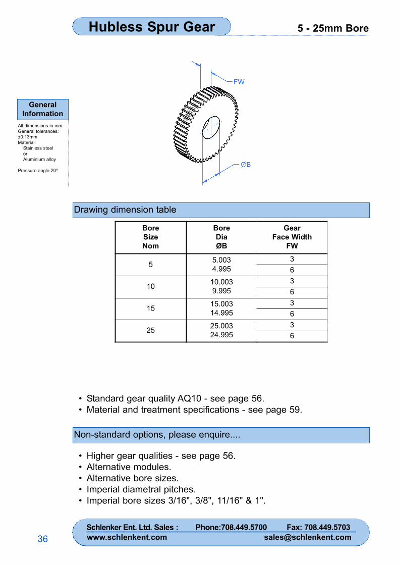
Drawing dimension table
Non-standard options, please enquire....
• Standard gear quality AQ10 - see page 56.• Material and treatment specifications - see page 59.
• Higher gear qualities - see page 56.• Alternative modules.• Alternative bore sizes.• Imperial diametral pitches.• Imperial bore sizes 3/16", 3/8", 11/16" & 1".
BoreSizeNom
BoreDiaØB
GearFace Width
FW
5 5.0034.995
36
10 10.0039.995
36
15 15.00314.995
36
25 25.00324.995
36
Schlenker Ent. Ltd. Sales : Phone:708.449.5700 Fax: 708.449.5703www.schlenkent.com [email protected]
5 - 25mm Bore Hubless Spur Gear
GeneralInformation
All dimensions in mmGeneral tolerances:±0.13mmMaterial:
Stainless steelorAluminium alloy
Pressure angle 20º
37
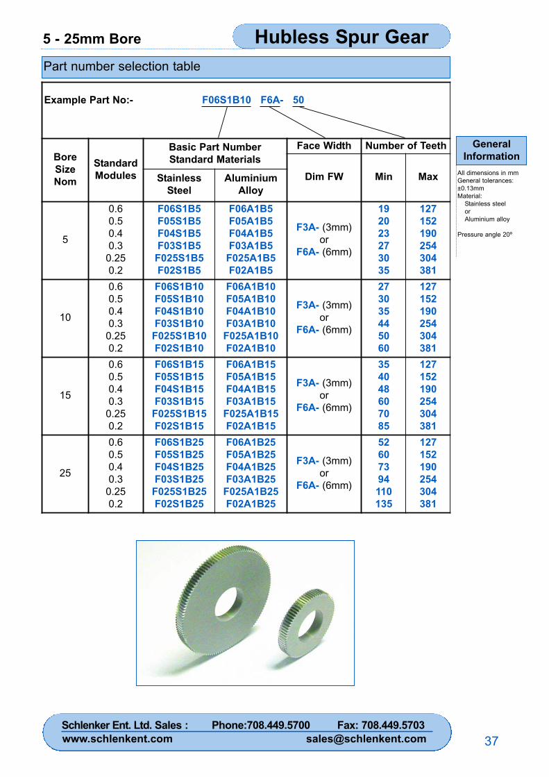
Part number selection table
Example Part No:- F06S1B10 F6A- 50
BoreSizeNom
StandardModules
Basic Part NumberStandard Materials
Face Width Number of Teeth
Dim FW Min MaxStainlessSteel
AluminiumAlloy
5
0.60.50.40.3
0.250.2
F06S1B5F05S1B5F04S1B5F03S1B5
F025S1B5F02S1B5
F06A1B5F05A1B5F04A1B5F03A1B5
F025A1B5F02A1B5
F3A- (3mm)or
F6A- (6mm)
192023273035
127152190254304381
10
0.60.50.40.3
0.250.2
F06S1B10F05S1B10F04S1B10F03S1B10
F025S1B10F02S1B10
F06A1B10F05A1B10F04A1B10F03A1B10
F025A1B10F02A1B10
F3A- (3mm)or
F6A- (6mm)
273035445060
127152190254304381
15
0.60.50.40.3
0.250.2
F06S1B15F05S1B15F04S1B15F03S1B15
F025S1B15F02S1B15
F06A1B15F05A1B15F04A1B15F03A1B15
F025A1B15F02A1B15
F3A- (3mm)or
F6A- (6mm)
354048607085
127152190254304381
25
0.60.50.40.3
0.250.2
F06S1B25F05S1B25F04S1B25F03S1B25
F025S1B25F02S1B25
F06A1B25F05A1B25F04A1B25F03A1B25
F025A1B25F02A1B25
F3A- (3mm)or
F6A- (6mm)
52607394110135
127152190254304381
Schlenker Ent. Ltd. Sales : Phone:708.449.5700 Fax: 708.449.5703www.schlenkent.com [email protected]
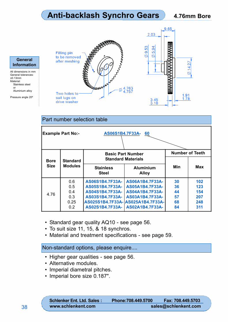
4.76mm BoreAnti-backlash Synchro Gears
GeneralInformation
All dimensions in mmGeneral tolerances:±0.13mmMaterial:
Stainless steelorAluminium alloy
Pressure angle 20º
38
Part number selection table
Non-standard options, please enquire....
• Standard gear quality AQ10 - see page 56.• To suit size 11, 15, & 18 synchros.• Material and treatment specifications - see page 59.
• Higher gear qualities - see page 56.• Alternative modules.• Imperial diametral pitches.• Imperial bore size 0.187".
Example Part No:- AS06S1B4.7F33A- 60
BoreSize
StandardModules
Basic Part NumberStandard Materials
Number of Teeth
Min MaxStainlessSteel
AluminiumAlloy
4.76
0.60.50.40.3
0.250.2
AS06S1B4.7F33A-AS05S1B4.7F33A-AS04S1B4.7F33A-AS03S1B4.7F33A-
AS025S1B4.7F33A-AS02S1B4.7F33A-
AS06A1B4.7F33A-AS05A1B4.7F33A-AS04A1B4.7F33A-AS03A1B4.7F33A-
AS025A1B4.7F33A-AS02A1B4.7F33A-
303644576884
102123154207248311
Schlenker Ent. Ltd. Sales : Phone:708.449.5700 Fax: 708.449.5703www.schlenkent.com [email protected]
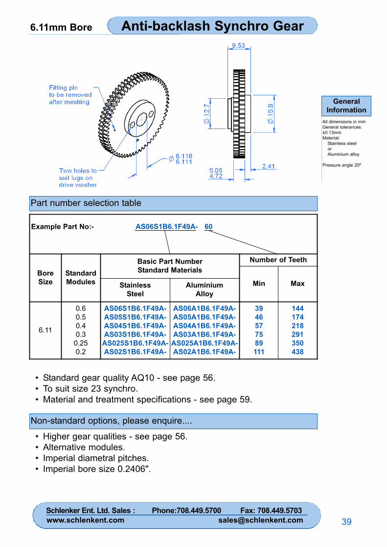
6.11mm Bore Anti-backlash Synchro Gear
GeneralInformation
All dimensions in mmGeneral tolerances:±0.13mmMaterial:
Stainless steelorAluminium alloy
Pressure angle 20º
39
Part number selection table
Non-standard options, please enquire....
• Standard gear quality AQ10 - see page 56.• To suit size 23 synchro.• Material and treatment specifications - see page 59.
• Higher gear qualities - see page 56.• Alternative modules.• Imperial diametral pitches.• Imperial bore size 0.2406".
Example Part No:- AS06S1B6.1F49A- 60
BoreSize
StandardModules
Basic Part NumberStandard Materials
Number of Teeth
Min MaxStainlessSteel
AluminiumAlloy
6.11
0.60.50.40.3
0.250.2
AS06S1B6.1F49A-AS05S1B6.1F49A-AS04S1B6.1F49A-AS03S1B6.1F49A-
AS025S1B6.1F49A-AS02S1B6.1F49A-
AS06A1B6.1F49A-AS05A1B6.1F49A-AS04A1B6.1F49A-AS03A1B6.1F49A-
AS025A1B6.1F49A-AS02A1B6.1F49A-
3946577589111
144174218291350438
Schlenker Ent. Ltd. Sales : Phone:708.449.5700 Fax: 708.449.5703www.schlenkent.com [email protected]
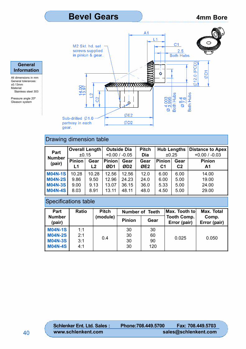
4mm BoreBevel Gears
GeneralInformation
All dimensions in mmGeneral tolerances:±0.13mmMaterial:
Stainless steel 303
Pressure angle 20ºGleason system
40
Drawing dimension table
Specifications table
PartNumber
(pair)
Overall Length±0.15
Outside Dia+0.00 / -0.05
PitchDia
Hub Lengths±0.25
Distance to Apex+0.00 / -0.03
PinionL1
GearL2
PinionØD1
GearØD2
GearØE2
PinionC1
GearC2
PinionA1
M04N-1SM04N-2SM04N-3SM04N-4S
10.289.869.008.03
10.289.509.138.91
12.5612.9613.0713.11
12.5624.2336.1548.11
12.024.036.048.0
6.006.005.334.50
6.005.005.005.00
14.0019.0024.0029.00
PartNumber
(pair)
Ratio Pitch(module)
Number of Teeth Max. Tooth toTooth Comp.Error (pair)
Max. TotalComp.
Error (pair)Pinion Gear
M04N-1SM04N-2SM04N-3SM04N-4S
1:12:13:14:1
0.4
30303030
306090
120
0.025 0.050
Schlenker Ent. Ltd. Sales : Phone:708.449.5700 Fax: 708.449.5703www.schlenkent.com [email protected]
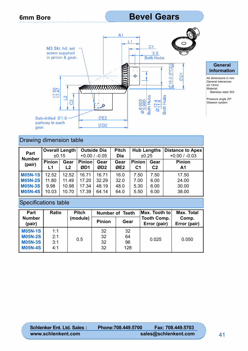
6mm Bore Bevel Gears
GeneralInformation
All dimensions in mmGeneral tolerances:±0.13mmMaterial:
Stainless steel 303
Pressure angle 20ºGleason system
41
Drawing dimension table
Specifications table
PartNumber
(pair)
Overall Length±0.15
Outside Dia+0.00 / -0.05
PitchDia
Hub Lengths±0.25
Distance to Apex+0.00 / -0.03
PinionL1
GearL2
PinionØD1
GearØD2
GearØE2
PinionC1
GearC2
PinionA1
M05N-1SM05N-2SM05N-3SM05N-4S
12.5211.809.98
10.03
12.5211.4910.9810.70
16.7117.2017.3417.39
16.7132.2948.1964.14
16.032.048.064.0
7.507.005.305.50
7.506.006.006.00
17.5024.0030.0038.00
PartNumber
(pair)
Ratio Pitch(module)
Number of Teeth Max. Tooth toTooth Comp.Error (pair)
Max. TotalComp.
Error (pair)Pinion Gear
M05N-1SM05N-2SM05N-3SM05N-4S
1:12:13:14:1
0.5
32323232
326496
128
0.025 0.050
Schlenker Ent. Ltd. Sales : Phone:708.449.5700 Fax: 708.449.5703www.schlenkent.com [email protected]
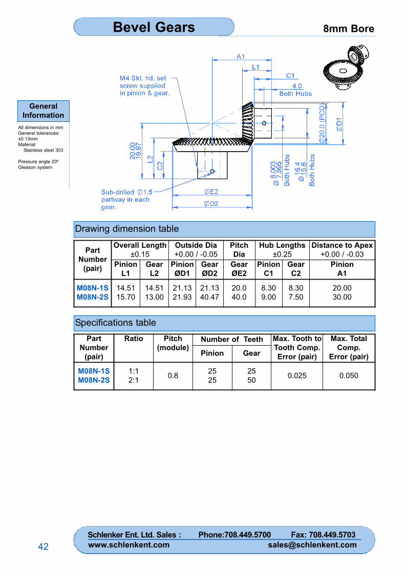
8mm BoreBevel Gears
GeneralInformation
All dimensions in mmGeneral tolerances:±0.13mmMaterial:
Stainless steel 303
Pressure angle 20ºGleason system
42
Drawing dimension table
Specifications table
PartNumber
(pair)
Overall Length±0.15
Outside Dia+0.00 / -0.05
PitchDia
Hub Lengths±0.25
Distance to Apex+0.00 / -0.03
PinionL1
GearL2
PinionØD1
GearØD2
GearØE2
PinionC1
GearC2
PinionA1
M08N-1SM08N-2S
14.5115.70
14.5113.00
21.1321.93
21.1340.47
20.040.0
8.309.00
8.307.50
20.0030.00
PartNumber
(pair)
Ratio Pitch(module)
Number of Teeth Max. Tooth toTooth Comp.Error (pair)
Max. TotalComp.
Error (pair)Pinion Gear
M08N-1SM08N-2S
1:12:1 0.8 25
252550 0.025 0.050
Schlenker Ent. Ltd. Sales : Phone:708.449.5700 Fax: 708.449.5703www.schlenkent.com [email protected]
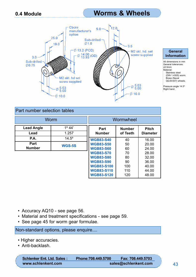
0.4 Module Worms & Wheels
GeneralInformation
All dimensions in mmGeneral tolerances:±0.5mmMaterial:
Stainless steel(DIN 1.4305) worm.Brass (NavalQQ-B-637) wheels.
Pressure angle 14.5ºRight hand.
43
Part number selection tables
Non-standard options, please enquire....
• Higher accuracies.• Anti-backlash.
• Accuracy AQ10 - see page 56.• Material and treatment specifications - see page 59.• See page 45 for worm gear formulae.
Lead Angle 1º 44’Lead 1.257P.A. 14.5ºPart
Number WGS-5S
PartNumber
Numberof Teeth
PitchDiameter
WGB83-S40WGB83-S50WGB83-S60WGB83-S70WGB83-S80WGB83-S90WGB83-S100WGB83-S110WGB83-S120
405060708090
100110120
16.0020.0024.0028.0032.0036.0040.0044.0048.00
Worm Wormwheel
Schlenker Ent. Ltd. Sales : Phone:708.449.5700 Fax: 708.449.5703www.schlenkent.com [email protected]
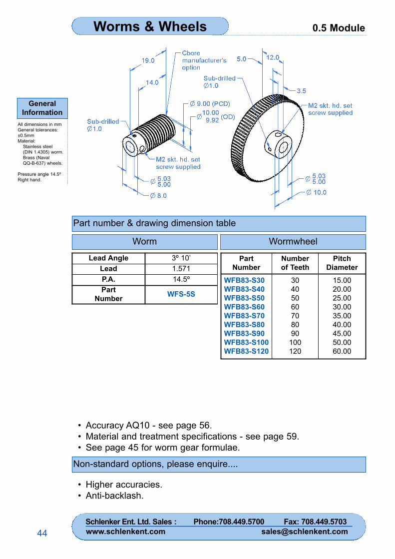
0.5 ModuleWorms & Wheels
GeneralInformation
All dimensions in mmGeneral tolerances:±0.5mmMaterial:
Stainless steel(DIN 1.4305) worm.Brass (NavalQQ-B-637) wheels.
Pressure angle 14.5ºRight hand.
44
Part number & drawing dimension table
Worm
Non-standard options, please enquire....
• Higher accuracies.• Anti-backlash.
• Accuracy AQ10 - see page 56.• Material and treatment specifications - see page 59.• See page 45 for worm gear formulae.
Lead Angle 3º 10’Lead 1.571P.A. 14.5ºPart
Number WFS-5S
PartNumber
Numberof Teeth
PitchDiameter
WFB83-S30WFB83-S40WFB83-S50WFB83-S60WFB83-S70WFB83-S80WFB83-S90WFB83-S100WFB83-S120
30405060708090
100120
15.0020.0025.0030.0035.0040.0045.0050.0060.00
Wormwheel
Schlenker Ent. Ltd. Sales : Phone:708.449.5700 Fax: 708.449.5703www.schlenkent.com [email protected]
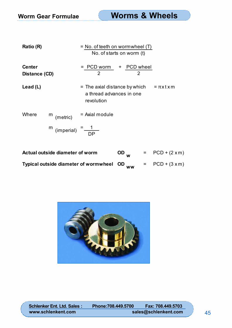
Worm Gear Formulae Worms & Wheels
45
Ratio (R) =
Center = +
Lead (L) = = π x t x m
Where m =
m = 1DP
OD =
OD =
PCD wheel2
Axial module
w
(metric)
PCD + (2 x m)
PCD + (3 x m)ww
Actual outside diameter of worm
Typical outside diameter of wormwheel
(imperial)
No. of teeth on wormwheel (T)No. of starts on worm (t)
PCD worm2
The axial distance by whicha thread advances in onerevolution
Distance (CD)
Schlenker Ent. Ltd. Sales : Phone:708.449.5700 Fax: 708.449.5703www.schlenkent.com [email protected]
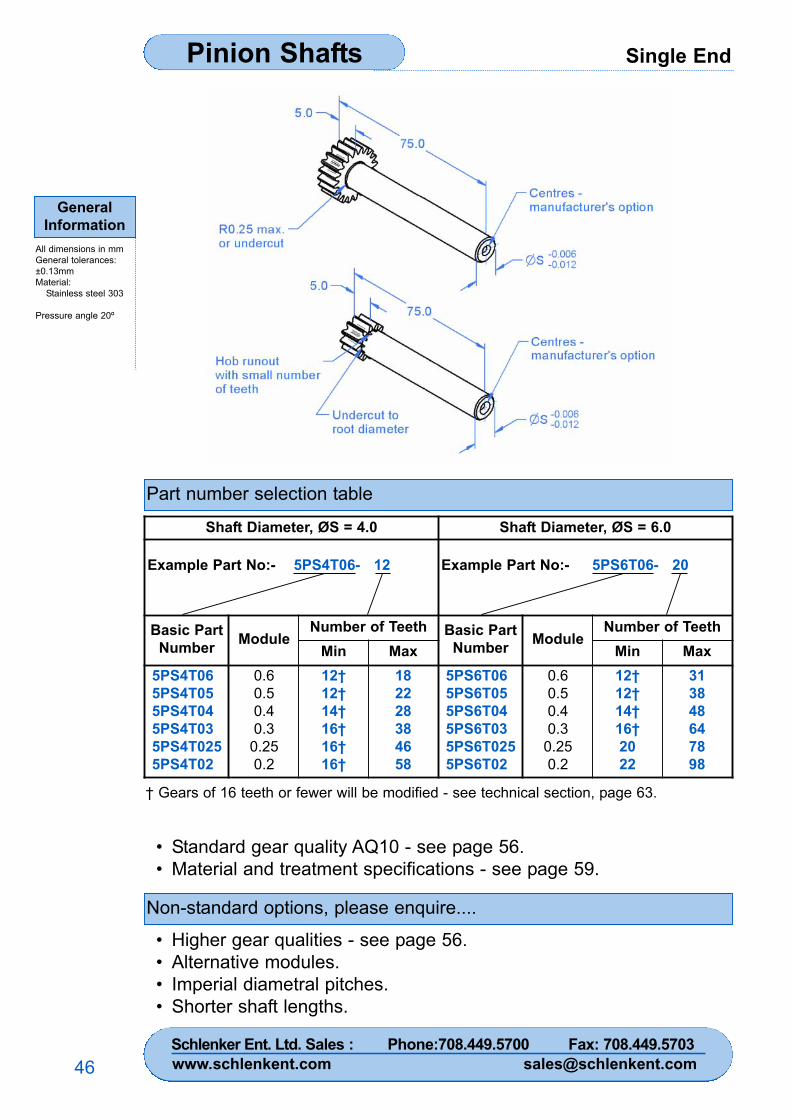
Single EndPinion Shafts
GeneralInformation
All dimensions in mmGeneral tolerances:±0.13mmMaterial:
Stainless steel 303
Pressure angle 20º
46
Part number selection table
Non-standard options, please enquire....
• Standard gear quality AQ10 - see page 56.• Material and treatment specifications - see page 59.
• Higher gear qualities - see page 56.• Alternative modules.• Imperial diametral pitches.• Shorter shaft lengths.
† Gears of 16 teeth or fewer will be modified - see technical section, page 63.
Shaft Diameter, ØS = 4.0 Shaft Diameter, ØS = 6.0
Example Part No:- 5PS4T06- 12 Example Part No:- 5PS6T06- 20
Basic PartNumber Module
Number of Teeth Basic PartNumber Module
Number of TeethMin Max Min Max
5PS4T065PS4T055PS4T045PS4T035PS4T0255PS4T02
0.60.50.40.3
0.250.2
12†12†14†16†16†16†
182228384658
5PS6T065PS6T055PS6T045PS6T035PS6T0255PS6T02
0.60.50.40.3
0.250.2
12†12†14†16†2022
313848647898
Schlenker Ent. Ltd. Sales : Phone:708.449.5700 Fax: 708.449.5703www.schlenkent.com [email protected]
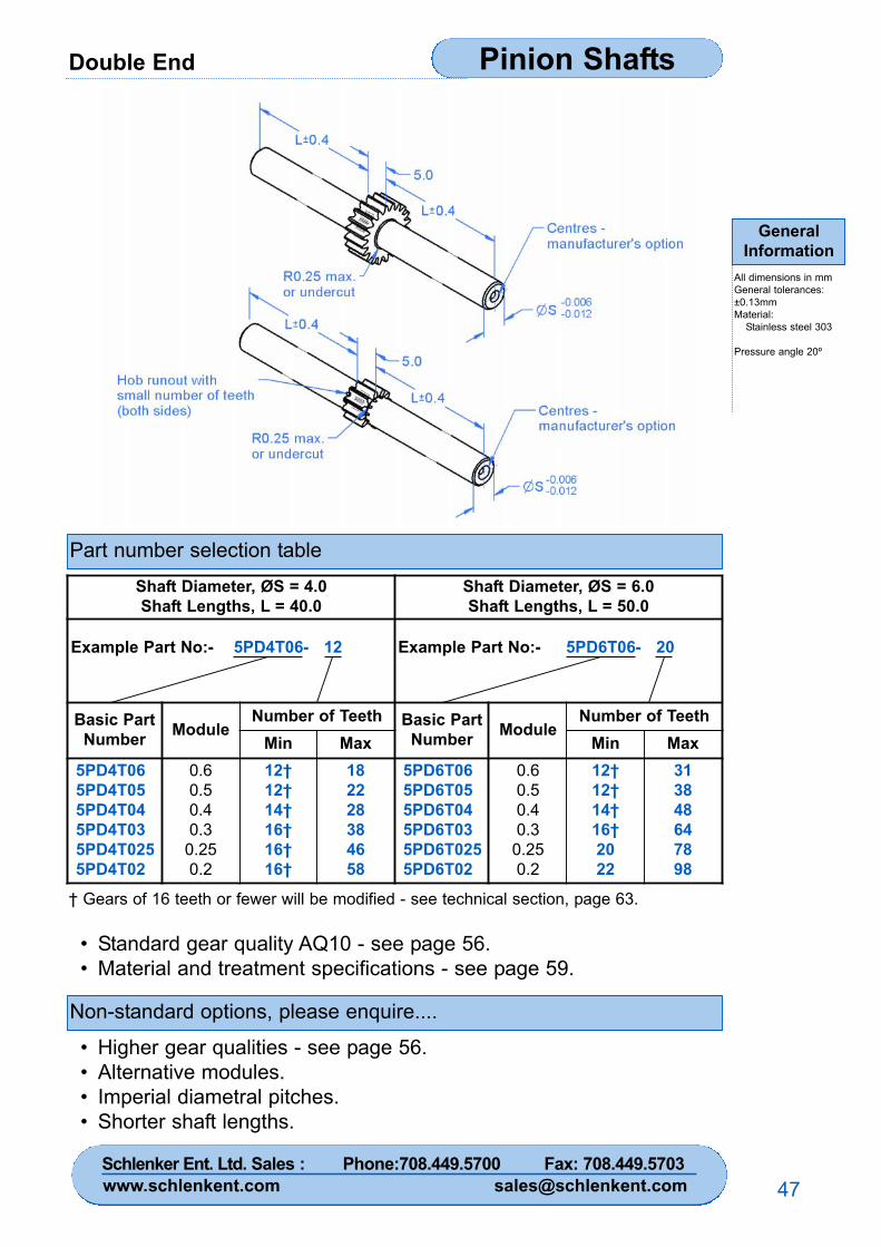
Double End Pinion Shafts
GeneralInformation
All dimensions in mmGeneral tolerances:±0.13mmMaterial:
Stainless steel 303
Pressure angle 20º
47
Part number selection table
Non-standard options, please enquire....
• Standard gear quality AQ10 - see page 56.• Material and treatment specifications - see page 59.
• Higher gear qualities - see page 56.• Alternative modules.• Imperial diametral pitches.• Shorter shaft lengths.
† Gears of 16 teeth or fewer will be modified - see technical section, page 63.
Shaft Diameter, ØS = 4.0Shaft Lengths, L = 40.0
Shaft Diameter, ØS = 6.0Shaft Lengths, L = 50.0
Example Part No:- 5PD4T06- 12 Example Part No:- 5PD6T06- 20
Basic PartNumber Module
Number of Teeth Basic PartNumber Module
Number of TeethMin Max Min Max
5PD4T065PD4T055PD4T045PD4T035PD4T0255PD4T02
0.60.50.40.3
0.250.2
12†12†14†16†16†16†
182228384658
5PD6T065PD6T055PD6T045PD6T035PD6T0255PD6T02
0.60.50.40.3
0.250.2
12†12†14†16†2022
313848647898
Schlenker Ent. Ltd. Sales : Phone:708.449.5700 Fax: 708.449.5703www.schlenkent.com [email protected]
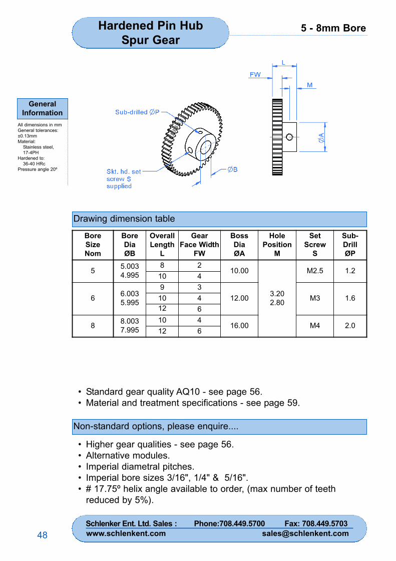
5 - 8mm BoreHardened Pin HubSpur Gear
GeneralInformation
All dimensions in mmGeneral tolerances:±0.13mmMaterial:
Stainless steel,17-4PH
Hardened to:36-40 HRc
Pressure angle 20º
48
Drawing dimension table
Non-standard options, please enquire....
• Standard gear quality AQ10 - see page 56.• Material and treatment specifications - see page 59.
• Higher gear qualities - see page 56.• Alternative modules.• Imperial diametral pitches.• Imperial bore sizes 3/16", 1/4" & 5/16".• # 17.75º helix angle available to order, (max number of teeth
reduced by 5%).
BoreSizeNom
BoreDiaØB
OverallLength
L
GearFace Width
FW
BossDiaØA
HolePosition
M
SetScrew
S
Sub-DrillØP
5 5.0034.995
8 210.00
3.202.80
M2.5 1.210 4
6 6.0035.995
9 312.00 M3 1.610 4
12 6
8 8.0037.995
10 416.00 M4 2.0
12 6
Schlenker Ent. Ltd. Sales : Phone:708.449.5700 Fax: 708.449.5703www.schlenkent.com [email protected]
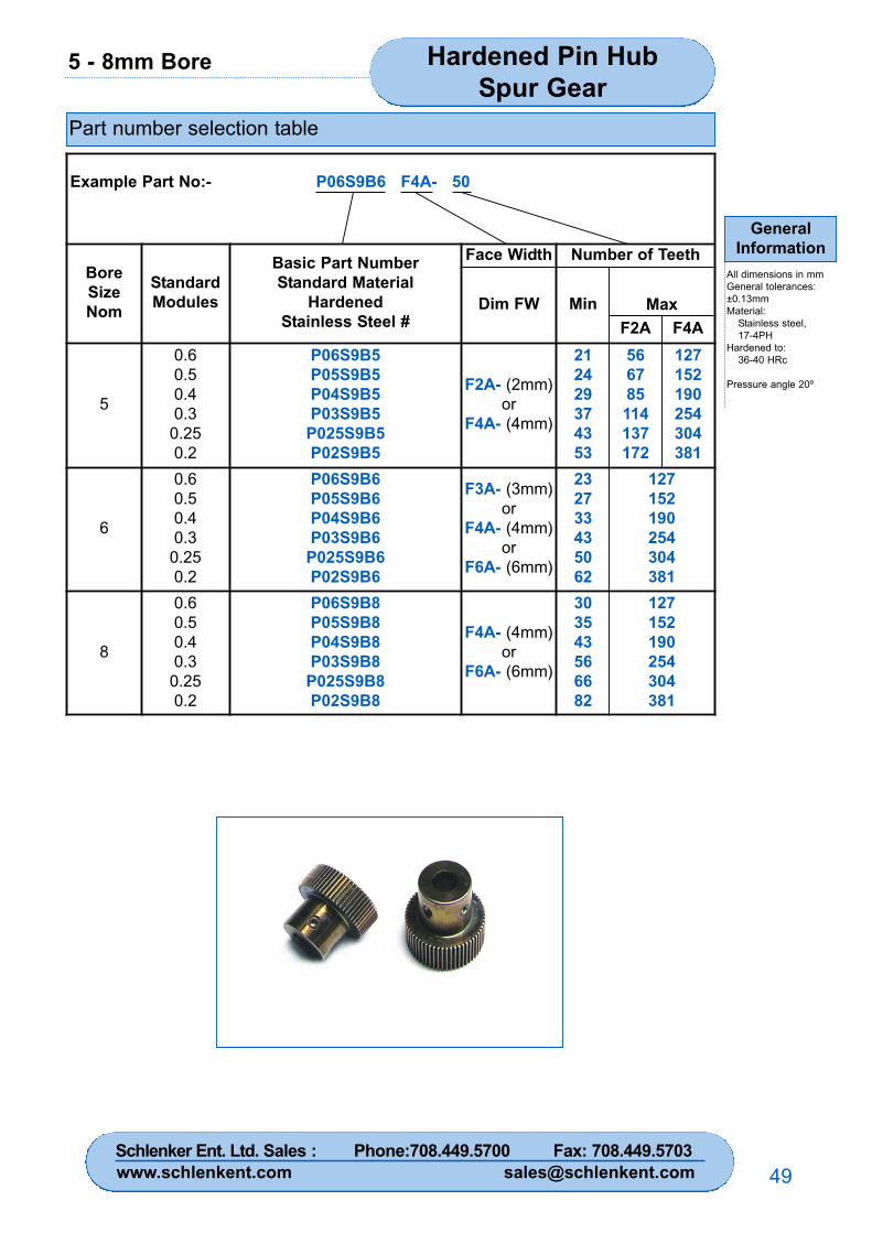
5 - 8mm Bore Hardened Pin HubSpur Gear
GeneralInformation
All dimensions in mmGeneral tolerances:±0.13mmMaterial:
Stainless steel,17-4PH
Hardened to:36-40 HRc
Pressure angle 20º
49
Part number selection table
Example Part No:- P06S9B6 F4A- 50
BoreSizeNom
StandardModules
Basic Part NumberStandard Material
HardenedStainless Steel #
Face Width Number of Teeth
Dim FW Min MaxF2A F4A
5
0.60.50.40.3
0.250.2
P06S9B5P05S9B5P04S9B5P03S9B5
P025S9B5P02S9B5
F2A- (2mm)or
F4A- (4mm)
212429374353
566785114137172
127152190254304381
6
0.60.50.40.3
0.250.2
P06S9B6P05S9B6P04S9B6P03S9B6
P025S9B6P02S9B6
F3A- (3mm)or
F4A- (4mm)or
F6A- (6mm)
232733435062
127152190254304381
8
0.60.50.40.3
0.250.2
P06S9B8P05S9B8P04S9B8P03S9B8
P025S9B8P02S9B8
F4A- (4mm)or
F6A- (6mm)
303543566682
127152190254304381
Schlenker Ent. Ltd. Sales : Phone:708.449.5700 Fax: 708.449.5703www.schlenkent.com [email protected]
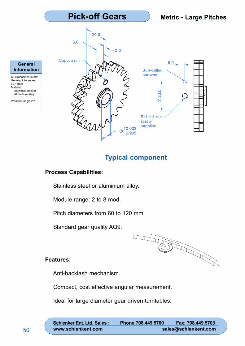
Metric - Large PitchesPick-off Gears
GeneralInformation
All dimensions in mmGeneral tolerances:±0.13mmMaterial:
Stainless steel orAluminium alloy
Pressure angle 20º
50
Typical component
Process Capabilities:
Stainless steel or aluminium alloy.
Module range: 2 to 8 mod.
Pitch diameters from 60 to 120 mm.
Standard gear quality AQ9.
Features:
Anti-backlash mechanism.
Compact, cost effective angular measurement.
Ideal for large diameter gear driven turntables.
Schlenker Ent. Ltd. Sales : Phone:708.449.5700 Fax: 708.449.5703www.schlenkent.com [email protected]
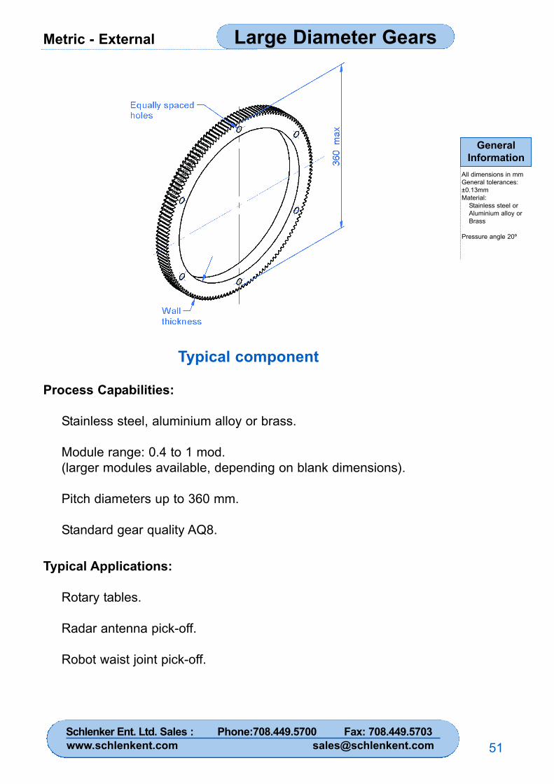
Metric - External Large Diameter Gears
GeneralInformation
All dimensions in mmGeneral tolerances:±0.13mmMaterial:
Stainless steel orAluminium alloy orBrass
Pressure angle 20º
51
Typical component
Process Capabilities:
Stainless steel, aluminium alloy or brass.
Module range: 0.4 to 1 mod.(larger modules available, depending on blank dimensions).
Pitch diameters up to 360 mm.
Standard gear quality AQ8.
Typical Applications:
Rotary tables.
Radar antenna pick-off.
Robot waist joint pick-off.
Schlenker Ent. Ltd. Sales : Phone:708.449.5700 Fax: 708.449.5703www.schlenkent.com [email protected]
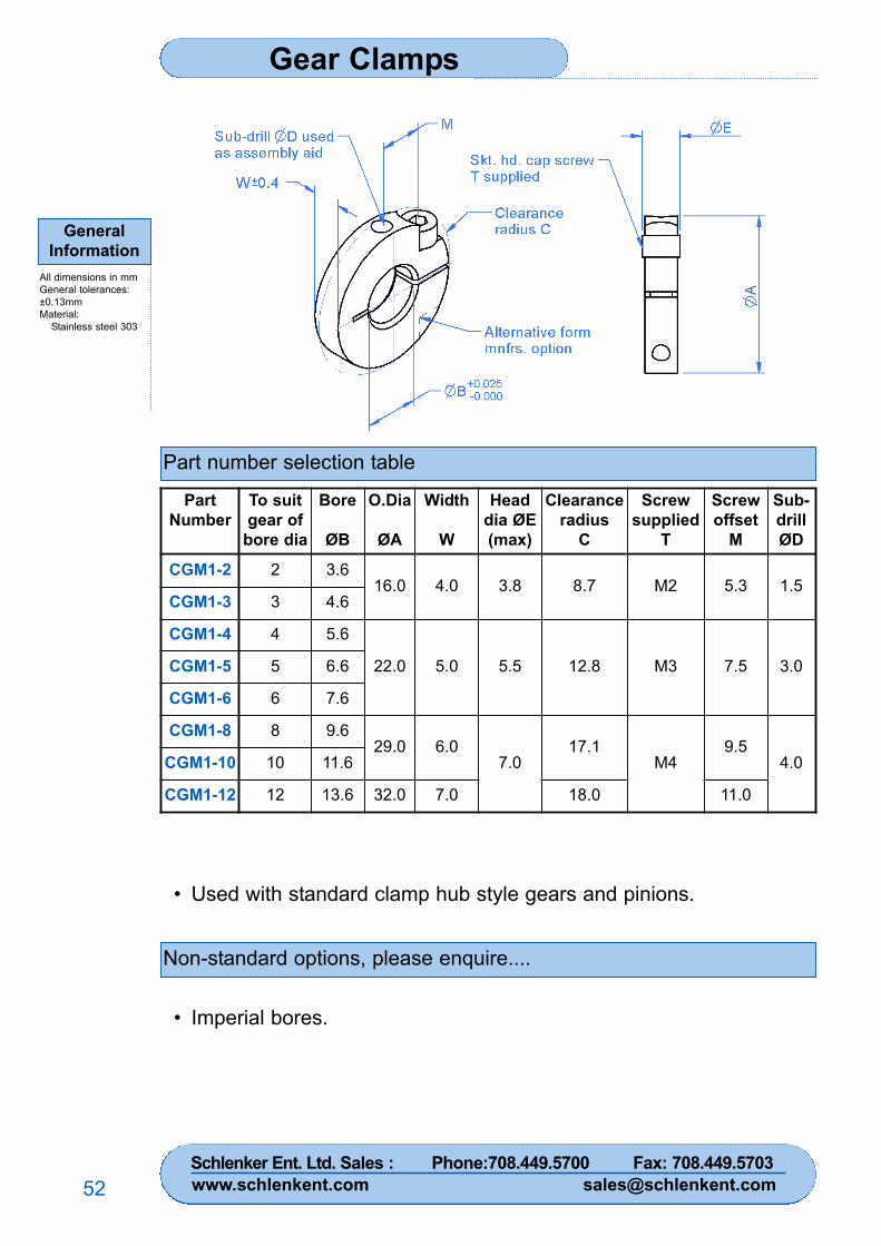
Gear Clamps
GeneralInformation
All dimensions in mmGeneral tolerances:±0.13mmMaterial:
Stainless steel 303
52
Part number selection table
Non-standard options, please enquire....
• Used with standard clamp hub style gears and pinions.
• Imperial bores.
PartNumber
To suitgear ofbore dia
Bore
ØB
O.Dia
ØA
Width
W
Headdia ØE(max)
Clearanceradius
C
Screwsupplied
T
Screwoffset
M
Sub-drillØD
CGM1-2 2 3.616.0 4.0 3.8 8.7 M2 5.3 1.5
CGM1-3 3 4.6
CGM1-4 4 5.6
22.0 5.0 5.5 12.8 M3 7.5 3.0CGM1-5 5 6.6
CGM1-6 6 7.6
CGM1-8 8 9.629.0 6.0
7.017.1
M49.5
4.0CGM1-10 10 11.6
CGM1-12 12 13.6 32.0 7.0 18.0 11.0
Schlenker Ent. Ltd. Sales : Phone:708.449.5700 Fax: 708.449.5703www.schlenkent.com [email protected]
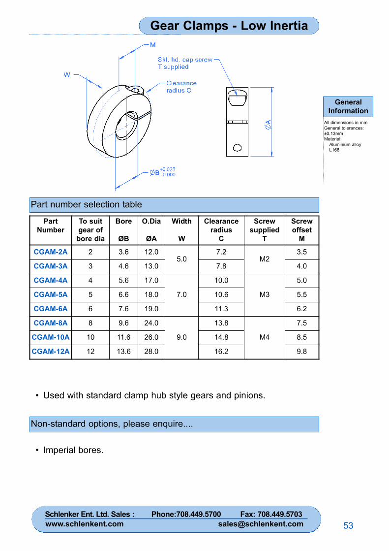
Gear Clamps - Low Inertia
GeneralInformation
All dimensions in mmGeneral tolerances:±0.13mmMaterial:
Aluminium alloy L168
53
Part number selection table
Non-standard options, please enquire....
• Used with standard clamp hub style gears and pinions.
• Imperial bores.
PartNumber
To suitgear ofbore dia
Bore
ØB
O.Dia
ØA
Width
W
Clearanceradius
C
Screwsupplied
T
Screwoffset
M
CGAM-2A 2 3.6 12.05.0
7.2M2
3.5
CGAM-3A 3 4.6 13.0 7.8 4.0
CGAM-4A 4 5.6 17.0
7.0
10.0
M3
5.0
CGAM-5A 5 6.6 18.0 10.6 5.5
CGAM-6A 6 7.6 19.0 11.3 6.2
CGAM-8A 8 9.6 24.0
9.0
13.8
M4
7.5
CGAM-10A 10 11.6 26.0 14.8 8.5
CGAM-12A 12 13.6 28.0 16.2 9.8
Schlenker Ent. Ltd. Sales : Phone:708.449.5700 Fax: 708.449.5703www.schlenkent.com [email protected]
Basic RangeStandard Belts & Pulleys
54
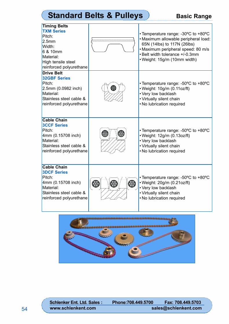
Timing BeltsTXM SeriesPitch:2.5mmWidth:6 & 10mmMaterial:High tensile steelreinforced polyurethane
• Temperature range: -30ºC to +80ºC• Maximum allowable peripheral load:65N (14lbs) to 117N (26lbs)
• Maximum peripheral speed: 80 m/s• Belt width tolerance +/-0.3mm• Weight: 15g/m (10mm width)
Drive Belt32GBF SeriesPitch:2.5mm (0.0982 inch)Material:Stainless steel cable &reinforced polyurethane
• Temperature range: -50ºC to +80ºC• Weight: 10g/m (0.11oz/ft)• Very low backlash• Virtually silent chain• No lubrication required
Cable Chain3CCF SeriesPitch:4mm (0.15708 inch)Material:Stainless steel cable &reinforced polyurethane
• Temperature range: -50ºC to +80ºC• Weight: 12g/m (0.13oz/ft)• Very low backlash• Virtually silent chain• No lubrication required
Cable Chain3DCF SeriesPitch:4mm (0.15708 inch)Material:Stainless steel cable &reinforced polyurethane
• Temperature range: -50ºC to +80ºC• Weight: 20g/m (0.21oz/ft)• Very low backlash• Virtually silent chain• No lubrication required
Schlenker Ent. Ltd. Sales : Phone:708.449.5700 Fax: 708.449.5703www.schlenkent.com [email protected]
Technical Information Standard Gear Range
55
Gear tolerances ...................................................... 56
Standards for fine pitch gears.................................. 57
Metric modules and circular pitches........................ 58
Materials and specifications .................................... 59
Spur gear geometry ..................................................60
Spur gear terminology ............................................ 61
Gears with small numbers of teeth.......................... 63
Engineering data .................................................... 64
Technical section index Page
Schlenker Ent. Ltd. Sales : Phone:708.449.5700 Fax: 708.449.5703www.schlenkent.com [email protected]
Technical InformationStandard Gear Range
56
Reliance precision instrumentation gears are manufactured using high accuracygearcutting equipment. Standard gears are produced in stainless steel, hardenedstainless steel, aluminium alloy and brass (wormwheels only). Alternative materials suchas PEEK™ plolymer or Delrin are available on request.
GEAR TOLERANCES
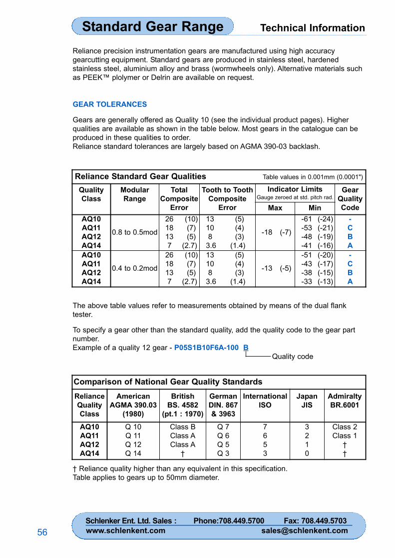
Gears are generally offered as Quality 10 (see the individual product pages). Higherqualities are available as shown in the table below. Most gears in the catalogue can beproduced in these qualities to order.Reliance standard tolerances are largely based on AGMA 390-03 backlash.
The above table values refer to measurements obtained by means of the dual flanktester.
To specify a gear other than the standard quality, add the quality code to the gear partnumber.Example of a quality 12 gear - P05S1B10F6A-100 B
Quality code
Reliance Standard Gear Qualities Table values in 0.001mm (0.0001")
QualityClass
ModularRange
TotalComposite
Error
Tooth to ToothComposite
Error
Indicator LimitsGauge zeroed at std. pitch rad.
GearQualityCodeMax Min
AQ10AQ11AQ12AQ14
0.8 to 0.5mod
26 (10)18 (7)13 (5)7 (2.7)
13 (5)10 (4)8 (3)
3.6 (1.4)
-18 (-7)
-61 (-24)-53 (-21)-48 (-19)-41 (-16)
-CBA
AQ10AQ11AQ12AQ14
0.4 to 0.2mod
26 (10)18 (7)13 (5)7 (2.7)
13 (5)10 (4)8 (3)
3.6 (1.4)
-13 (-5)
-51 (-20)-43 (-17)-38 (-15)-33 (-13)
-CBA
Comparison of National Gear Quality StandardsRelianceQualityClass
AmericanAGMA 390.03
(1980)
BritishBS. 4582
(pt.1 : 1970)
GermanDIN. 867& 3963
InternationalISO
JapanJIS
AdmiraltyBR.6001
AQ10AQ11AQ12AQ14
Q 10Q 11Q 12Q 14
Class BClass AClass A
†
Q 7Q 6Q 5Q 3
7653
3210
Class 2Class 1
††
† Reliance quality higher than any equivalent in this specification.Table applies to gears up to 50mm diameter.
Schlenker Ent. Ltd. Sales : Phone:708.449.5700 Fax: 708.449.5703www.schlenkent.com [email protected]

Technical Information Standard Gear Range
57
RELIANCE GEAR STANDARDS FOR FINE PITCH GEARS
The table below is a comparison between Reliance (AGMA) and equivalent UKspecifications.
14 12 10 14 12 10 1 2 3 1 2 3 A B C D
- -
7 13 26 7 13 26 18 31 48 18 31 48 15 25 40 1002.7 5 10 2.7 5 10 7 12 19 7 12 19 6 10 16 40
3.6 8 10 3.6 8 10 8 13 23 8 13 23 5 13 23 581.4 3 4 1.4 3 4 3 5 9 3 5 9 2 5 9 23
6
864
*Total Composite Error(0.001mm)
(0.0001")
†
*Tooth to Tooth Composite Error
80 32
(0.0001")
(0.001mm)
Tota
l in
dica
tor r
ange
(0.0
001"
)
2220
65
18
30282624
12
20
1210
15105
302520
14
51015
2
810
024
1614
Standard Pitch Circle Radius
Tota
l ind
icat
or ra
nge
(0.0
01m
m)
354045505560
7075
Method 'A' Method 'B'
2530
0
0.8 to 0.5mod 0.4 to 0.2mod
35
Quality Number ClassBacklash Designation "C"
1964
++
Class
BS 4582 Pt1(BS 978 Pt1)BR 6001(1)
StandardAdmiralty390.02AGMA
*AGMA values quoted are for over 20T up to 50mm (2") diameter Admiralty & B.S.Tooth to tooth errors are for over 30T.† Minimum indicator level 0.006" or 0.15mm.
For numbers of teeth outside the range consult the relevant specification.
Schlenker Ent. Ltd. Sales : Phone:708.449.5700 Fax: 708.449.5703www.schlenkent.com [email protected]
Technical InformationStandard Gear Range
58
STANDARD MODULES AND CIRCULAR PITCHES - METRIC
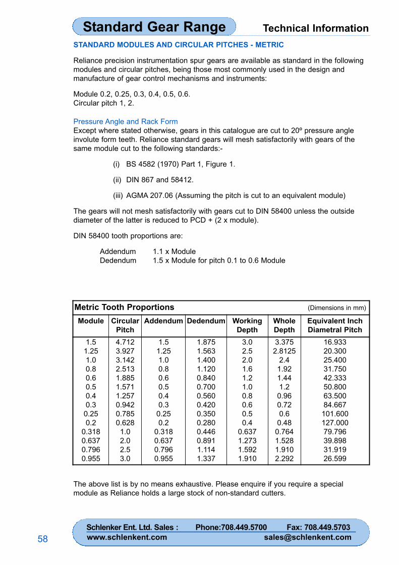
Reliance precision instrumentation spur gears are available as standard in the followingmodules and circular pitches, being those most commonly used in the design andmanufacture of gear control mechanisms and instruments:
Module 0.2, 0.25, 0.3, 0.4, 0.5, 0.6.Circular pitch 1, 2.
Pressure Angle and Rack FormExcept where stated otherwise, gears in this catalogue are cut to 20º pressure angleinvolute form teeth. Reliance standard gears will mesh satisfactorily with gears of thesame module cut to the following standards:-
(i) BS 4582 (1970) Part 1, Figure 1.
(ii) DIN 867 and 58412.
(iii) AGMA 207.06 (Assuming the pitch is cut to an equivalent module)
The gears will not mesh satisfactorily with gears cut to DIN 58400 unless the outsidediameter of the latter is reduced to PCD + (2 x module).
DIN 58400 tooth proportions are:
Addendum 1.1 x ModuleDedendum 1.5 x Module for pitch 0.1 to 0.6 Module
The above list is by no means exhaustive. Please enquire if you require a specialmodule as Reliance holds a large stock of non-standard cutters.
Metric Tooth Proportions (Dimensions in mm)
Module CircularPitch
Addendum Dedendum WorkingDepth
WholeDepth
Equivalent InchDiametral Pitch
1.51.251.00.80.60.50.40.3
0.250.2
0.3180.6370.7960.955
4.7123.9273.1422.5131.8851.5711.2570.9420.7850.628
1.02.02.53.0
1.51.251.00.80.60.50.40.3
0.250.2
0.3180.6370.7960.955
1.8751.5631.4001.1200.8400.7000.5600.4200.3500.2800.4460.8911.1141.337
3.02.52.01.61.21.00.80.60.50.4
0.6371.2731.5921.910
3.3752.8125
2.41.921.441.2
0.960.720.6
0.480.7641.5281.9102.292
16.93320.30025.40031.75042.33350.80063.50084.667
101.600127.00079.79639.89831.91926.599
Schlenker Ent. Ltd. Sales : Phone:708.449.5700 Fax: 708.449.5703www.schlenkent.com [email protected]
Technical Information Standard Gear Range
59
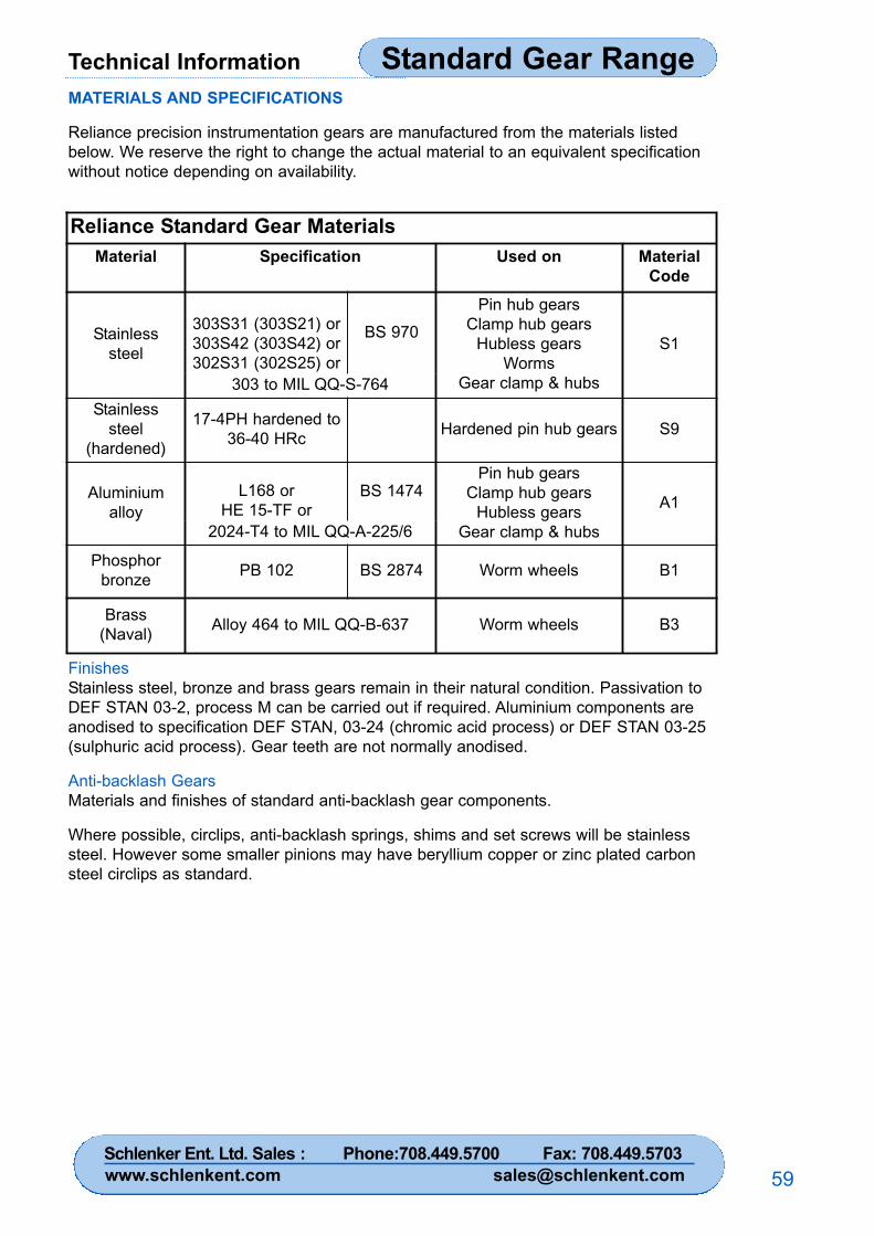
MATERIALS AND SPECIFICATIONS
Reliance precision instrumentation gears are manufactured from the materials listedbelow. We reserve the right to change the actual material to an equivalent specificationwithout notice depending on availability.
FinishesStainless steel, bronze and brass gears remain in their natural condition. Passivation toDEF STAN 03-2, process M can be carried out if required. Aluminium components areanodised to specification DEF STAN, 03-24 (chromic acid process) or DEF STAN 03-25(sulphuric acid process). Gear teeth are not normally anodised.
Anti-backlash GearsMaterials and finishes of standard anti-backlash gear components.
Where possible, circlips, anti-backlash springs, shims and set screws will be stainlesssteel. However some smaller pinions may have beryllium copper or zinc plated carbonsteel circlips as standard.
Reliance Standard Gear MaterialsMaterial Specification Used on Material
Code
Stainlesssteel
303S31 (303S21) or303S42 (303S42) or302S31 (302S25) or
BS 970Pin hub gears
Clamp hub gearsHubless gears
WormsGear clamp & hubs
S1
303 to MIL QQ-S-764Stainless
steel(hardened)
17-4PH hardened to36-40 HRc Hardened pin hub gears S9
Aluminiumalloy
L168 orHE 15-TF or
BS 1474Pin hub gears
Clamp hub gearsHubless gears
Gear clamp & hubs
A1
2024-T4 to MIL QQ-A-225/6
Phosphorbronze PB 102 BS 2874 Worm wheels B1
Brass(Naval) Alloy 464 to MIL QQ-B-637 Worm wheels B3
Schlenker Ent. Ltd. Sales : Phone:708.449.5700 Fax: 708.449.5703www.schlenkent.com [email protected]
Technical InformationStandard Gear Range
60
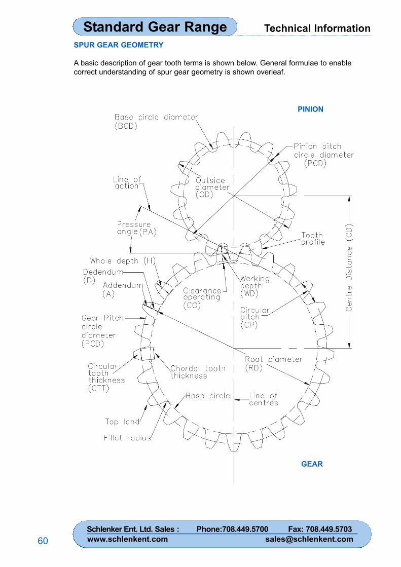
SPUR GEAR GEOMETRY
A basic description of gear tooth terms is shown below. General formulae to enablecorrect understanding of spur gear geometry is shown overleaf.
PINION
GEAR
Schlenker Ent. Ltd. Sales : Phone:708.449.5700 Fax: 708.449.5703www.schlenkent.com [email protected]
Technical Information Standard Gear Range
61
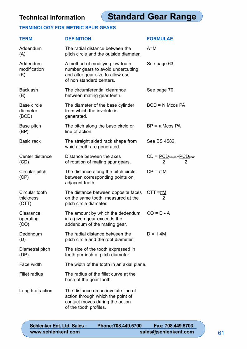
TERMINOLOGY FOR METRIC SPUR GEARS
TERM DEFINITION FORMULAE
Addendum The radial distance between the A=M(A) pitch circle and the outside diameter.
Addendum A method of modifying low tooth See page 63modification number gears to avoid undercutting(K) and alter gear size to allow use
of non standard centers.
Backlash The circumferential clearance See page 70(B) between mating gear teeth.
Base circle The diameter of the base cylinder BCD = N·Mcos PAdiameter from which the involute is(BCD) generated.
Base pitch The pitch along the base circle or BP = π Mcos PA(BP) line of action.
Basic rack The straight sided rack shape from See BS 4582.which teeth are generated.
Center distance Distance between the axes CD = PCDpinion+PCDgear
(CD) of rotation of mating spur gears. 2 2
Circular pitch The distance along the pitch circle CP = π M(CP) between corresponding points on
adjacent teeth.
Circular tooth The distance between opposite faces CTT =πMthickness on the same tooth, measured at the 2(CTT) pitch circle diameter.
Clearance The amount by which the dedendum CO = D - Aoperating in a given gear exceeds the(CO) addendum of the mating gear.
Dedendum The radial distance between the D = 1.4M(D) pitch circle and the root diameter.
Diametral pitch The size of the tooth expressed in(DP) teeth per inch of pitch diameter.
Face width The width of the tooth in an axial plane.
Fillet radius The radius of the fillet curve at thebase of the gear tooth.
Length of action The distance on an involute line ofaction through which the point ofcontact moves during the actionof the tooth profiles.
Schlenker Ent. Ltd. Sales : Phone:708.449.5700 Fax: 708.449.5703www.schlenkent.com [email protected]
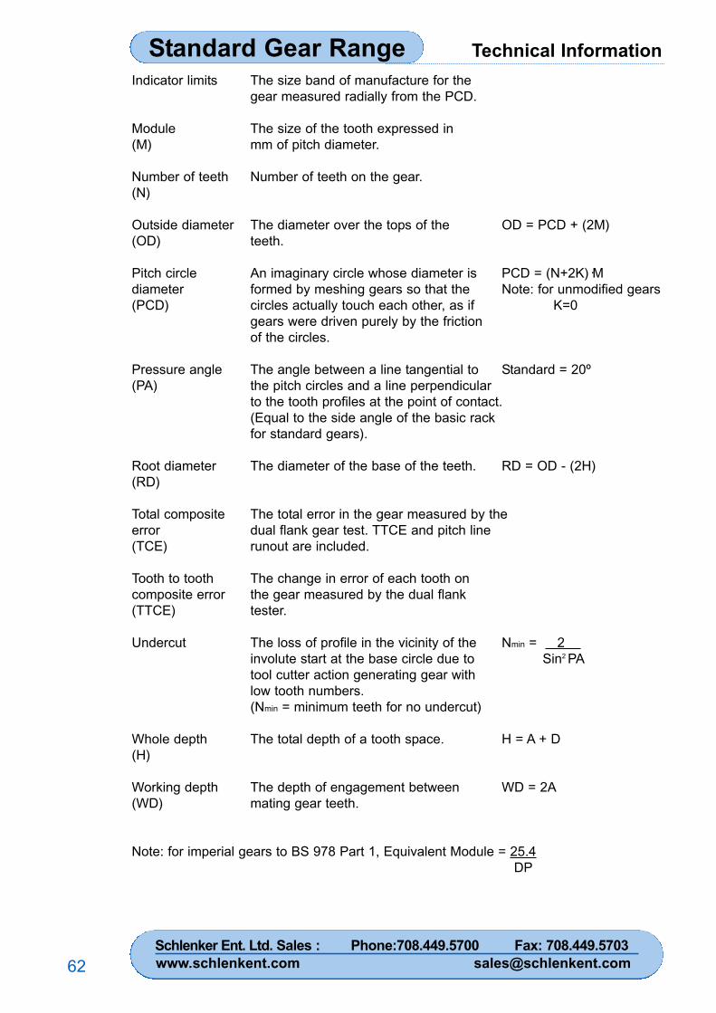
Technical InformationStandard Gear Range
62
Indicator limits The size band of manufacture for thegear measured radially from the PCD.
Module The size of the tooth expressed in(M) mm of pitch diameter.
Number of teeth Number of teeth on the gear.(N)
Outside diameter The diameter over the tops of the OD = PCD + (2M)(OD) teeth.
Pitch circle An imaginary circle whose diameter is PCD = (N+2K)·Mdiameter formed by meshing gears so that the Note: for unmodified gears(PCD) circles actually touch each other, as if K=0
gears were driven purely by the frictionof the circles.
Pressure angle The angle between a line tangential to Standard = 20º(PA) the pitch circles and a line perpendicular
to the tooth profiles at the point of contact.(Equal to the side angle of the basic rackfor standard gears).
Root diameter The diameter of the base of the teeth. RD = OD - (2H)(RD)
Total composite The total error in the gear measured by theerror dual flank gear test. TTCE and pitch line(TCE) runout are included.
Tooth to tooth The change in error of each tooth oncomposite error the gear measured by the dual flank(TTCE) tester.
Undercut The loss of profile in the vicinity of the Nmin = 2 involute start at the base circle due to Sin2 PAtool cutter action generating gear withlow tooth numbers.(Nmin = minimum teeth for no undercut)
Whole depth The total depth of a tooth space. H = A + D(H)
Working depth The depth of engagement between WD = 2A(WD) mating gear teeth.
Note: for imperial gears to BS 978 Part 1, Equivalent Module = 25.4DP
Schlenker Ent. Ltd. Sales : Phone:708.449.5700 Fax: 708.449.5703www.schlenkent.com [email protected]
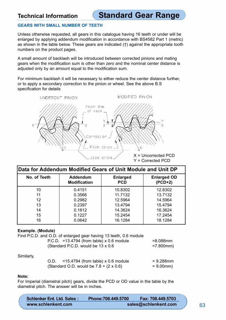
Technical Information Standard Gear Range
63
GEARS WITH SMALL NUMBER OF TEETH
Unless otherwise requested, all gears in this catalogue having 16 teeth or under will beenlarged by applying addendum modification in accordance with BS4582 Part 1 (metric)as shown in the table below. These gears are indicated (†) against the appropriate toothnumbers on the product pages.
A small amount of backlash will be introduced between corrected pinions and matinggears when the modification sum is other than zero and the nominal center distance isadjusted only by an amount equal to the modification sum.
For minimum backlash it will be necessary to either reduce the center distance further,or to apply a secondary correction to the pinion or wheel. See the above B.Sspecification for details
Example. (Module)Find P.C.D. and O.D. of enlarged gear having 13 teeth, 0.6 module
P.C.D. =13.4794 (from table) x 0.6 module =8.088mm(Standard P.C.D. would be 13 x 0.6 =7.800mm)
Similarly,O.D. =15.4794 (from table) x 0.6 module = 9.288mm(Standard O.D. would be 7.8 + (2 x 0.6) = 9.00mm)
Note:For Imperial (diametral pitch) gears, divide the PCD or OD value in the table by thediametral pitch. The answer will be in inches.
X = Uncorrected PCDY = Corrected PCD
Data for Addendum Modified Gears of Unit Module and Unit DPNo. of Teeth Addendum
ModificationEnlarged
PCDEnlarged OD
(PCD+2)10111213141516
0.41510.35660.29820.23970.18120.12270.0642
10.830211.713212.596413.479414.362415.245416.1284
12.830213.713214.596415.479416.362417.245418.1284
Schlenker Ent. Ltd. Sales : Phone:708.449.5700 Fax: 708.449.5703www.schlenkent.com [email protected]
Technical InformationStandard Gear Range
64
ENGINEERING DATA
For instrumentation Reliance normally recommend stainless steel pinions mating withaluminium alloy gears. Generally the pinion is subjected to most wear since itexperiences a higher number of stress cycles than the wheel. This combination ofmaterials tends to balance the wear between the pinion and the gear.
1. Gear materialsStainless steelThe 300 series stainless steels are used for gears when maximum corrosion resistanceis required. They are ‘true’ stainless steels containing 18% chromium and 8% nickel.Gears made from 303 stainless steel are essentially nonmagnetic and cannot behardened by heat treatment. They are recommended for low torque applications as theirmechanical properties and resistance are low.
Aluminium alloyGears made from aluminium alloy are widely used in measuring applications. Its lightweight offers reduced inertia. The inertia of an aluminium alloy gear is approximately35% that of a steel gear. In particular, aluminium alloy L168 offers excellent corrosionresistance when anodised, moderately good mechanical properties and good stability.
Hardened stainless steel17-4PH is a precipitation hardening stainless steel that offers a remarkable combinationof high strength and hardness. Its high chromium content, (15-17.5%), makes it anexcellent material for arduous environments.
Phosphor bronzeAs a gear material phosphor bronze has a fine grain and good resistance to tooth slidingwear hence its use as a worm wheel material.
2. InstallationGears in this catalogue are designed to be a slide fit on the shafts. The gears areavailable with four fixing methods: standard clamp, Reli-a-Grip™ clamp, pins and setscrews.
Traditional clamp hub style gears have a gear hub with a relatively thin wall partially split.The clamp is a close fit on the hub and is compressed when the clamp screw istightened. Clamping gears on to the shaft offers extremely easy assembly with the bestassembled accuracy. However, as the fastening depends upon friction it can only beused in low torque applications.
Reli-a-Grip™ clamps are designed as an integral clamp alternative to the standardseparate gear clamp, reducing component count and improving ease of assembly yetmaintaining a high level of assembled accuracy. When the clamp screw is tightened theclamp deflects in such a manner providing an even pressure over the contact area. Aswith the standard clamp, this fastening depends on friction and should only be used inlower torque applications.
Pin type gears are supplied as standard with a set screw and a sub-drilled hole. The setscrew should be used to position the gear on the shaft during the drilling and pinningoperation and can be removed once the gear is secure.
The sub-drilled hole provides a lead in for the drilling operation. It is recommended thatdrilling and pinning is completed outside the gear box and the gear is thoroughly cleanedafterwards.
Schlenker Ent. Ltd. Sales : Phone:708.449.5700 Fax: 708.449.5703www.schlenkent.com [email protected]
Technical Information Standard Gear Range
65
In less critical applications the set screw may be used to retain the gear on the shaft. Toavoid damaging the shaft and to make removal of the gear easier the set screw shouldseat on a small flat, or dimple on the shaft.
3. LubricationAll gears should be lubricated, but there are variations in degree.
Highly loaded precision gears should be in enclosed assembles with completelubrication to obtain the best possible hydrodynamic film. The system can be splash,spray or force fed, depending on the application. Moderately loaded precision gears,such as fractional horsepower systems, should be enclosed with oil or grease lubricationwhich can be spread by splash or dip lubrication.
Lightly loaded gears in instrumentation systems need only have a marginal boundarylubrication as provided by periodically wiped on oils or grease. In many instances a lightcoat of Rocol MT-LM or similar molybdenum disulphide grease will suffice for the life ofthe system. Anti-backlash gears should not be directly lubricated except via a very lightapplication on the mating pinion.
Negligibly loaded fine instrument gears need only a brushed on film of light oil as asimple means of reducing friction.
4. SpeedThe maximum pitch line velocity for stainless steel meshing with aluminium alloy withboundary lubrication is approximately 5,300 mm/sec, (for a pair of meshing actuationgears correctly lubricated, this rises to approximately 8,000 mm/sec). This represents5,000 rpm on measurement gears of 20mm diameter, (and 7,500 rpm on actuation gearsof 20mm diameter).
For speeds in excess of this and other material combinations please consult Reliancetechnical sales.
5. Gear LoadingThe gears in this catalogue can be used for both feedback and actuation systems. Theloads and material selection will depend on the application. In general a feedbacksystem is designed to maintain accuracy and an actuation system is designed totransmit power.
Actuation GearsThe following analysis is intended to give a guide to the load capacity of a pair of spurgears. To simplify the calculations, a number of assumptions have been made. It mustbe noted that in many applications this will give a conservative estimate of the gearcapacity, therefore, in critical applications an exact analysis must be completed.Please consult the relevant gear standards or Reliance technical sales.
The analysis is based on AGMA 2001-B88 and assumes the following:
1. The gears are simply supported in rolling element bearings.2. Pinion revolutions >107.
3. Gears are grease lubricated.4. Reliability of 1 failure in 100 is acceptable.5. Gear material is 17-4PH hardened.
Schlenker Ent. Ltd. Sales : Phone:708.449.5700 Fax: 708.449.5703www.schlenkent.com [email protected]
Technical InformationStandard Gear Range
66
The basic load capacity (Fb) of a pair of spur gears is defined as the maximumtangential force at which they can operate indefinitely.
Fb has two values: one calculated from tooth root strength, (Fbs) and one for tooth flankpitting (Fbw). The useful or transmitted load capacity, Ft, is usually less than Fb due totransient or dynamic loads generated within the mechanism.
For tooth root strength Fts = Fbs/Ka Ka & Ca = Application factorsFor tooth flank pitting (wear) Ftw = Fbw/Ca
Both calculation should be made and the lower value used.
The application factors Ka and Ca make allowance for any externally applied loads inexcess of the nominal tangential force Fb and they are most accurately determined bydirect measurement. In determining application factors, consideration should be given tothe fact that many prime movers develop momentary peak torques appreciably greaterthan those determined by the nominal ratings of either the prime mover or the drivenequipment. There are many possible sources of overload which should be considered,including system vibrations, acceleration torques, overspeeds, variations in systemoperation and changes in process load. Impact loads due to reversing across backlashcan be significant in servo systems.
As a general guide application factors for a motor gear system range from 1.0 foruniform loads up to 1.75 where heavy shock loads are anticipated.
Fb = Basic load capacity (Fbs & Fbw)For strength Fbs = 177.7 x J x F x M x K [N] N = Number of teeth
J = Geometry factor, strengthI = Geometry factor, wear
For wear Fbw = 14.64 x N x I x F x M x Kv [N] F = Face width of smallest gearM = ModuleKv = Dynamic factor
(i) Number or teeth - this is the number of teeth in the gear being analysed.
(ii) Geometry factors, I and JThese factors take account of the effect of tooth proportions on stress. The bendingstrength geometry factor, (J) takes account of the shape of the tooth. The wearresistance geometry factor, (I) takes account of the radii of curvature of the contactingtooth profiles. Please see the graphs on page 67 and 68.
(iii) Face width, FThis is the face width of the smallest gear in mm.
(iv) Module, MThis is the gear module expressed as shown on the respective gear pages.
(v) Dynamic factor, KvThis accounts for internally generated gear tooth loads which are induced by the non-conjugate meshing action of the gear teeth.
Schlenker Ent. Ltd. Sales : Phone:708.449.5700 Fax: 708.449.5703www.schlenkent.com [email protected]
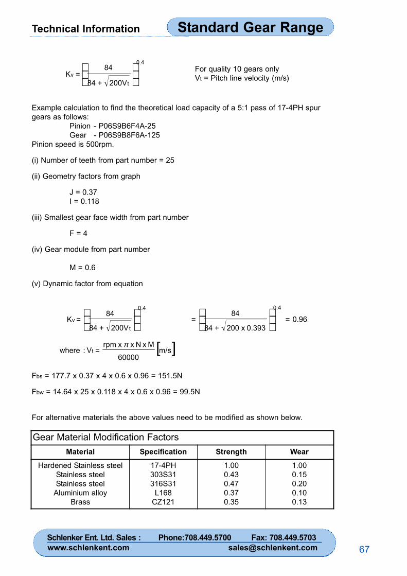
Technical Information Standard Gear Range
67
Example calculation to find the theoretical load capacity of a 5:1 pass of 17-4PH spurgears as follows:
Pinion - P06S9B6F4A-25Gear - P06S9B8F6A-125
Pinion speed is 500rpm.
(i) Number of teeth from part number = 25
(ii) Geometry factors from graph
J = 0.37I = 0.118
(iii) Smallest gear face width from part number
F = 4
(iv) Gear module from part number
M = 0.6
(v) Dynamic factor from equation
0.4
t v
200V 84
84K
+=
[ ]m/s60000
M x N x x rpm V:where t
π=
0.4
tv
200V 84
84 K
+=
For quality 10 gears onlyVt = Pitch line velocity (m/s)
0.960.393 x 200 84
840.4
=+
=
Fbs = 177.7 x 0.37 x 4 x 0.6 x 0.96 = 151.5N
Fbw = 14.64 x 25 x 0.118 x 4 x 0.6 x 0.96 = 99.5N
For alternative materials the above values need to be modified as shown below.
Gear Material Modification FactorsMaterial Specification Strength Wear
Hardened Stainless steelStainless steelStainless steel
Aluminium alloyBrass
17-4PH303S31316S31
L168CZ121
1.000.430.470.370.35
1.000.150.200.100.13
Schlenker Ent. Ltd. Sales : Phone:708.449.5700 Fax: 708.449.5703www.schlenkent.com [email protected]
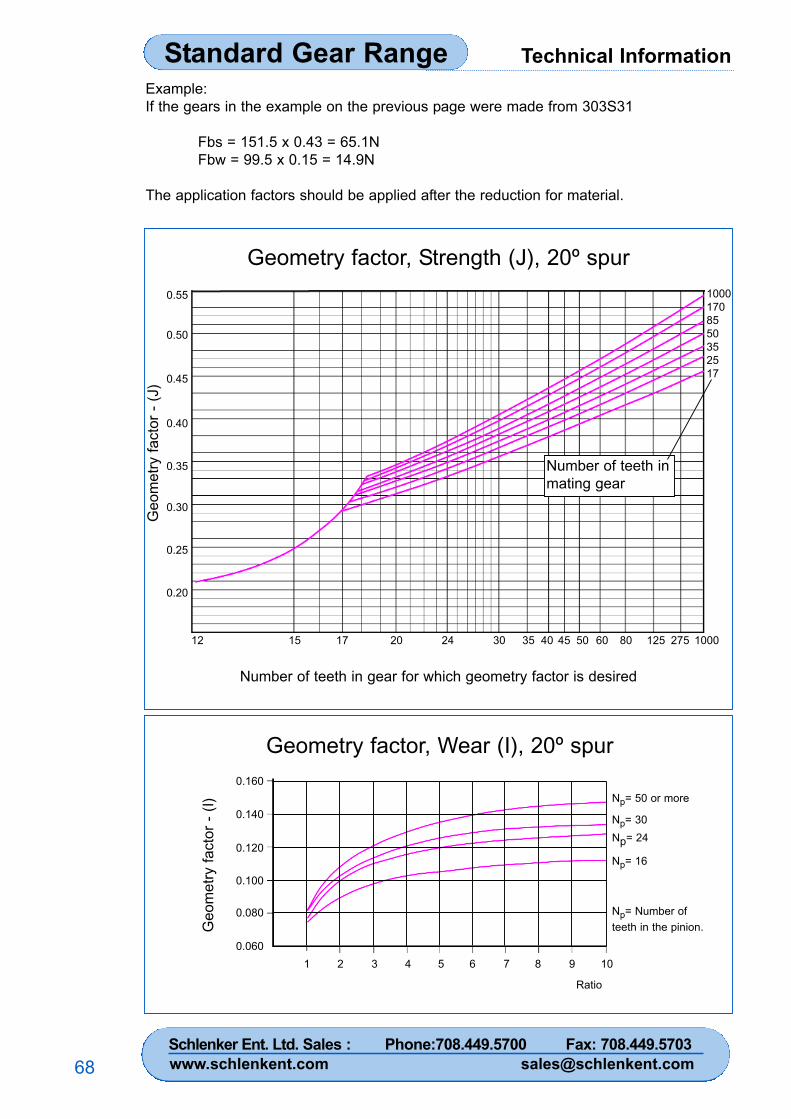
Technical InformationStandard Gear Range
68
Example:If the gears in the example on the previous page were made from 303S31
Fbs = 151.5 x 0.43 = 65.1NFbw = 99.5 x 0.15 = 14.9N
The application factors should be applied after the reduction for material.
Geometry factor, Strength (J), 20º spur
Number of teeth in gear for which geometry factor is desired
0.55
0.50
0.45
0.40
0.35
0.30
0.25
0.20
12 15 17 20 24 30 35 40 45 50 60 80 125 275 1000
Geo
met
ry fa
ctor
- (J
)
10001708550352517
Number of teeth inmating gear
Geometry factor, Wear (I), 20º spur
Geo
met
ry fa
ctor
- (I)
0.160
0.140
0.120
0.100
0.080
0.0601 32 4 5 6 7 8 9 10
Ratio
Np= 50 or more
Np= 30Np= 24
Np= 16
Np= Number ofteeth in the pinion.
Schlenker Ent. Ltd. Sales : Phone:708.449.5700 Fax: 708.449.5703www.schlenkent.com [email protected]
Technical Information Standard Gear Range
69
Instrumentation and Feedback SystemsGears and components designed for the precise transmission of angular positiongenerally work at the low torque levels normally associated with servo components suchas synchros, resolvers, optical encoders etc. Tooth loads of 1.2N per mm face widthshould result in an adequate accurate life. Higher loads will tend to increase deflectionsof gear teeth, shafts, bearings etc, resulting in significant values of lost motion and adecrease in life.
eg. To find the maximum advisable torque on a gear 40mm diameter x 3mm face width.
Torque = force x radius = 1.2 x 3 x 0.04/2 = 0.072Nm (10oz.in.)
Anti-backlash Gear Spring TensionIn order for anti-backlash gears to function as anti-backlash devices, it is necessary toensure that the spring tension will provide sufficient torque to overcome the friction andacceleration torque in the system, ie the spring torque must be capable ofdriving/accelerating the gear train and any associated components.
The spring tension capability of anti-backlash gears listed in this catalogue willadequately cope with the low torques normally encountered.
As a general guide, torque settings on anti-backlash gears of 108 to 180 gmcm (1.5 to2.5 oz.in.) will suffice in most applications. Ideally the spring torque should be set to theminimum at which the anti-backlash gear performs satisfactory, thus avoidingunnecessary high preload on the gear teeth and premature wear.
6. Lost Motion and Backlash ControlThe following section deals with lost motion, which we know to be one of the basicproblems in designing fine pitch gear trains. The accepted definition of lost motion is theamount by which the output shaft may be turned without turning the input shaft.
It may be thought that lost motion is a function of the gear cutting operation alone, but, infact the teeth of the gears may contribute very little to the overall lost motion value. Acomplete understanding of all the elements which induce lost motion is essential in orderto achieve a well designed gear train. The following factors must be individuallyconsidered for their own contribution to overall lost motion in the gear train.
(a) Nominal center distance.
(b) Center distance tolerance.
(c) Size and tolerance of mating gears.
(d) Total composite error of gears.
(e) Fits between bores, shafts and bearings.
(f) Bearing accuracy (class).
(g) Radial play of bearings.
(h) Shaft straightness and alignment.
(i) Fits between electrical and/or mechanical component spigot diameters,and housing bores.
Schlenker Ent. Ltd. Sales : Phone:708.449.5700 Fax: 708.449.5703www.schlenkent.com [email protected]
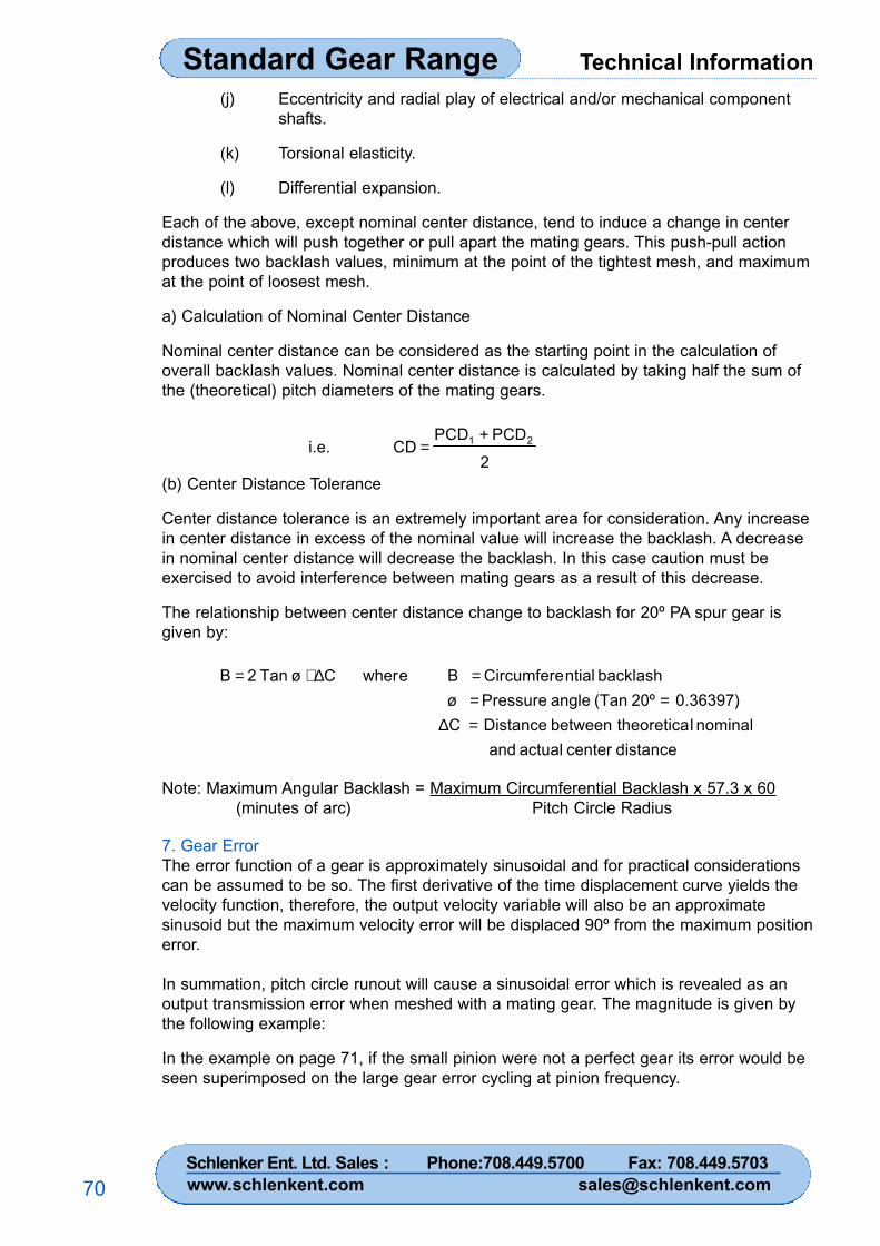
Technical InformationStandard Gear Range
70
(j) Eccentricity and radial play of electrical and/or mechanical componentshafts.
(k) Torsional elasticity.
(l) Differential expansion.
Each of the above, except nominal center distance, tend to induce a change in centerdistance which will push together or pull apart the mating gears. This push-pull actionproduces two backlash values, minimum at the point of the tightest mesh, and maximumat the point of loosest mesh.
a) Calculation of Nominal Center Distance
Nominal center distance can be considered as the starting point in the calculation ofoverall backlash values. Nominal center distance is calculated by taking half the sum ofthe (theoretical) pitch diameters of the mating gears.
2PCDPCD
CD i.e. 21 +=
(b) Center Distance Tolerance
Center distance tolerance is an extremely important area for consideration. Any increasein center distance in excess of the nominal value will increase the backlash. A decreasein nominal center distance will decrease the backlash. In this case caution must beexercised to avoid interference between mating gears as a result of this decrease.
The relationship between center distance change to backlash for 20º PA spur gear isgiven by:
distance center actual and nominal ltheoretica between Distance C
0.36397)20º (Tan angle Pressure ø backlash ntialCircumfere B e wherCø Tan 2 B
=∆==
=∆⋅=
Note: Maximum Angular Backlash = Maximum Circumferential Backlash x 57.3 x 60(minutes of arc) Pitch Circle Radius
7. Gear ErrorThe error function of a gear is approximately sinusoidal and for practical considerationscan be assumed to be so. The first derivative of the time displacement curve yields thevelocity function, therefore, the output velocity variable will also be an approximatesinusoid but the maximum velocity error will be displaced 90º from the maximum positionerror.
In summation, pitch circle runout will cause a sinusoidal error which is revealed as anoutput transmission error when meshed with a mating gear. The magnitude is given bythe following example:
In the example on page 71, if the small pinion were not a perfect gear its error would beseen superimposed on the large gear error cycling at pinion frequency.
Schlenker Ent. Ltd. Sales : Phone:708.449.5700 Fax: 708.449.5703www.schlenkent.com [email protected]
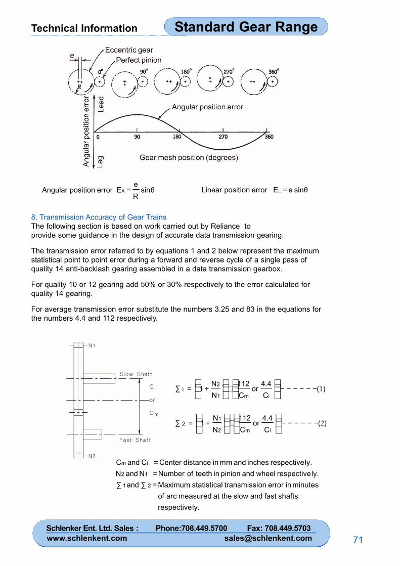
Technical Information Standard Gear Range
71
θ= sinRe
E error position Angular A θ= sin e E error position Linear L
8. Transmission Accuracy of Gear TrainsThe following section is based on work carried out by Reliance toprovide some guidance in the design of accurate data transmission gearing.
The transmission error referred to by equations 1 and 2 below represent the maximumstatistical point to point error during a forward and reverse cycle of a single pass ofquality 14 anti-backlash gearing assembled in a data transmission gearbox.
For quality 10 or 12 gearing add 50% or 30% respectively to the error calculated forquality 14 gearing.
For average transmission error substitute the numbers 3.25 and 83 in the equations forthe numbers 4.4 and 112 respectively.
ly.respective shafts fast andslow the at measuredarc of
minutes in error ontransmissi lstatistica Maximum and ly.respective wheeland pinion in teeth of Number N and N
ly.respective inches and mm in distance Center C and C
21
12
im
=∑∑==
)(C4.4or
C112
NN1
)(C4.4
orC112
NN
1
im2
12
im1
2
2
11
−−−−−−⋅+=∑
−−−−−−⋅+=∑
Schlenker Ent. Ltd. Sales : Phone:708.449.5700 Fax: 708.449.5703www.schlenkent.com [email protected]
NotesProduct Title
72
Standard Gear Range
Note - As a result of continuous product development, Reliance reserves the rightwithout prior notice to change dimensions where this does not affect the function of theitem.
Schlenker Ent. Ltd. Sales : Phone:708.449.5700 Fax: 708.449.5703www.schlenkent.com [email protected]
Contacts Product Title
73
Standard Gear Range
For full range of our products please visit us at:
www.schlenkent.com
Schlenker Ent. Ltd. Sales : Phone:708.449.5700 Fax: 708.449.5703www.schlenkent.com [email protected]
Schlenker Enterprises, Ltd.P.O. Box 9277, Lombard, IL 60148-9277, U.S.A.
Phone: (USA) 708.449.5700Fax: (USA) 708.449.5703
www.schlenkent.come-mail: [email protected]
ISO 9001Quality assured to BS/EN/ISO 9001, Reliance specializes in gears, gearboxes,assemblies and associated components which are used in instrumentation,measurement, diagnostic equipment and light actuation systems. Reliance aims toprovide its customers with a single source for the design, production, assembly andtesting of high quality mechanical components and electro-mechanical assemblies.
Standard ProductsFor over thirty years, Reliance has provided a standard range of precision mechanicalcomponents from stock or on short delivery. This service allows design engineers toorder in small quantities at stock prices in order to develop prototypes effectively.Dedicated manufacturing facilities enable larger quantities to be supplied for fullproduction requirements.
Dust Free AssemblyReliance also has over 350 square metres of clean room space for the assembly,wiring and testing of precision gearboxes, optical equipment and scientificinstruments to customers' specifications. Particle counts in the clean rooms meet ISO14644-1 Class ISO 7, but are readily adaptable to more stringent standards ifrequired.
For engineering assistance and to place an order please contact us at:
(USA) 708.449.5700