Embed Size (px)
Citation preview

Reliable Internet Routing
Martin Suchara
A Dissertation
Presented to the Faculty
of Princeton University
in Candidacy for the Degree
of Doctor of Philosophy
Recommended for Acceptance
By the Department of
Computer Science
Adviser: Professor Jennifer Rexford
September 2011

c© Copyright by Martin Suchara, 2011. All rights reserved.

Abstract
Network routing algorithms responsible for selecting paths to destinations have a profound
impact on network reliability experienced by the network users. Unfortunately, performance of
state-of-the-art routing algorithms often falls short of users’ expectations.
(i) The flexibility with which operators of independently administered networks can choose
their routing policies allows them to make selections that are “conflicting” and may lead to route
oscillations. Oscillating routes have a negative impact on performance experienced by the user, and
also cause overloading of the routers with control messages. (ii) Interdomain routing in the Internet
is based on trust. As a result, false route announcements can be made by a malicious network
operator. Such false announcements can be made even without knowledge of the network operator,
e.g., due to accidentally misconfigurations or router hijacking. False route announcements may lead
to denial of service, or worse yet, traffic can be intercepted without detection of both the sender
and recipient. (iii) Even if network routes are stable and secure, unexpected equipment failures
may cause performance degradation. It is difficult to pre-configure current routing protocols with
all possible failures in mind, and not enough flexibility is offered to balance load in the network
evenly.
This thesis addresses these three challenging problems. (i) We provide a new theoretical model
of interdomain routing and derive the necessary and sufficient conditions that determine which pol-
icy combinations lead to route oscillations. Moreover, we also provide a practical polynomial-time
algorithm that allows network operators to verify the existence of such conflicts. (ii) To secure rout-
ing against malicious attacks, we offer a new secure routing protocol that, unlike earlier attempts,
is incrementally deployable. Our solution can protect both participants and non-participants if
as few as 5–10 independently administered domains deploy our solution. (iii) To handle traffic
engineering in the presence of failures, we propose a new architecture that optimizes load bal-
ancing for a wide range of failure scenarios. Our architecture supports flexible splitting of traffic
over multiple precomputed paths, with efficient path-level failure detection and automatic load
balancing over the remaining paths.
Collectively, the contributions of the dissertation provide tools that improve routing reliability
and as a result network performance perceived by the user.
iii

Acknowledgments
I would like to thank my advisor Jennifer Rexford for her support not only during the ups but
also the downs of my graduate career at Princeton. Words cannot express Jennifer’s passion for
teaching and mentoring. She worked with me selflessly and was happy to discuss new ideas, give
feedback about my writing style, presentations, and career advice. I admire her sharp intellect,
professionalism with which she deals with all tasks, and ability to prioritize. I would also like to
thank Jennifer for her support and encouragement to present my results at conferences and as a
speaker at several universities.
I would like to thank Mung Chiang for being my co-advisor and mentor in my early years
at Princeton. I highly value Mung’s expertise in optimization theory. His mentoring helped
me to understand and tackle the complex optimization problems I faced when I worked on this
dissertation. I would also like to thank all my thesis committee members, Mung Chiang, Gordon
Wilfong, Ed Felten, and Mike Freedman for their feedback on my thesis.
I am grateful for the help I received from all the co-authors of the papers that I published. I
am especially indebted to Alex Fabrikant, Ioannis Avramopoulos, and Jiayue He. Alex taught me
how to think like a theorist, provided help during my job search, and was a great friend. I thank
Ioannis and Jiayue for their creative ideas and co-authoring several major publications with me.
I am very lucky to have worked with a number of excellent researchers at AT&T Labs Research
where I spent two summers. In particular, I am grateful to my mentors Robert Doverspike, and
Dahai Xu for their mentoring and encouragement to work on practical problems with real-world
impact. I also appreciate the numerous interactions I had with David Johnson. In addition, I
owe thanks to Quynh Nguyen, Kostas Oikonomou, Rakesh Sinha, Kobus van der Merwe, and
Jennifer Yates for help and advice with understanding the operation of the AT&T’s backbone,
measurement, data collection, and data processing that I needed to finish this dissertation.
I thank Barbara Terhal and Sergey Bravyi at IBM research where I spent one summer working
on quantum error correcting codes. I especially thank you for your time explaining me the concepts
of a new research area I wasn’t familiar with.
I thank my fellow Cabernet group members: Minlan Yu, Yaping Zhu, Eric Keller, Wenjie (Joe)
Jiang, Rob Harrison, Michael Schapira, Sharon Goldberg, Haakon Ringberg, Elliott Karpilovsky,
Changhoon Kim, Yi Wang, Steven Ko, Nate Foster, Rui Zhang-Shen, Matthew Caesar, and others.
iv

You not only provided me with help when I needed it, but you were also great friends. I also thank
Melissa Lawson, the administrator in the Computer Science Department.
I was fortunate to work with and co-supervise two bright undergraduate students, Will Fisher
and Umar Javed. Thank you for your hard work, you were great students.
Writing this dissertation would not be possible without the support of research grants from
AFOSR, NSF and AT&T. In addition, my graduate study at Princeton was partly supported by
the Gordon Wu Fellowship, and my two summer internships at AT&T by the DARPA CORONET
Program.
I thank my parents for their love, support and encouragement. Without them this accomplish-
ment would have been impossible.
v

Contents
Abstract . . . . . . . . . . . . . . . . . . . . . . . . . . . . . . . . . . . . . . . . . . . . . iii
1 Introduction 4
1.1 Routing in the Internet . . . . . . . . . . . . . . . . . . . . . . . . . . . . . . . . . 5
1.1.1 Interdomain Routing . . . . . . . . . . . . . . . . . . . . . . . . . . . . . . . 5
1.1.2 Intradomain Routing . . . . . . . . . . . . . . . . . . . . . . . . . . . . . . . 6
1.2 Challenges with Network Reliability . . . . . . . . . . . . . . . . . . . . . . . . . . 8
1.2.1 Interdomain Routing Policies Leading to Oscillations . . . . . . . . . . . . . 8
1.2.2 Interdomain Routing is not Secure against Malicious Attacks . . . . . . . . 10
1.2.3 Traffic Engineering after a Failure . . . . . . . . . . . . . . . . . . . . . . . 12
2 Detecting Routing Protocol Oscillations 14
2.1 Introduction . . . . . . . . . . . . . . . . . . . . . . . . . . . . . . . . . . . . . . . . 14
2.1.1 Spurious Selection of Lower-Ranked Routes . . . . . . . . . . . . . . . . . . 15
2.1.2 DPVP Convergence . . . . . . . . . . . . . . . . . . . . . . . . . . . . . . . 16
2.2 The Stable Paths Problem (SPP) . . . . . . . . . . . . . . . . . . . . . . . . . . . . 18
2.3 DPVP: BGP Model with Spurious Updates . . . . . . . . . . . . . . . . . . . . . . 19
2.3.1 Modeling the Spurious Updates . . . . . . . . . . . . . . . . . . . . . . . . . 20
2.3.2 Dynamic Path Vector Protocol (DPVP) . . . . . . . . . . . . . . . . . . . . 20
2.3.3 A Shorthand Notation . . . . . . . . . . . . . . . . . . . . . . . . . . . . . . 22
2.4 Expressiveness of DPVP . . . . . . . . . . . . . . . . . . . . . . . . . . . . . . . . . 23
2.4.1 Route Flap Damping . . . . . . . . . . . . . . . . . . . . . . . . . . . . . . . 24
2.4.2 MRAI Timer . . . . . . . . . . . . . . . . . . . . . . . . . . . . . . . . . . . 25
vi

2.4.3 Lack of Route Visibility . . . . . . . . . . . . . . . . . . . . . . . . . . . . . 27
2.4.4 Router Queues . . . . . . . . . . . . . . . . . . . . . . . . . . . . . . . . . . 29
2.4.5 Experimental Architectures . . . . . . . . . . . . . . . . . . . . . . . . . . . 30
2.5 All Spurious Updates can be Realized . . . . . . . . . . . . . . . . . . . . . . . . . 30
2.6 Impact on Convergence . . . . . . . . . . . . . . . . . . . . . . . . . . . . . . . . . 33
2.6.1 Slower than Expected Convergence . . . . . . . . . . . . . . . . . . . . . . . 33
2.6.2 BGP Without a Reel Unsafe . . . . . . . . . . . . . . . . . . . . . . . . . . 35
2.7 BGP Safety with Spurious Updates . . . . . . . . . . . . . . . . . . . . . . . . . . . 36
2.7.1 No Dispute Wheel Implies Safety . . . . . . . . . . . . . . . . . . . . . . . . 36
2.7.2 Safety with Filtering . . . . . . . . . . . . . . . . . . . . . . . . . . . . . . . 38
2.8 The Necessary and Sufficient Conditions . . . . . . . . . . . . . . . . . . . . . . . . 42
2.9 Practical Algorithm for Safety Verification . . . . . . . . . . . . . . . . . . . . . . . 46
2.9.1 The “DeCoy” safety verification algorithm . . . . . . . . . . . . . . . . . . . 46
2.9.2 Verifying Safety in Practice . . . . . . . . . . . . . . . . . . . . . . . . . . . 49
2.10 Hardness of Some Safety Verification Formulations . . . . . . . . . . . . . . . . . . 53
2.11 Summary . . . . . . . . . . . . . . . . . . . . . . . . . . . . . . . . . . . . . . . . . 57
3 Preventing Address Prefix Hijacks 59
3.1 Introduction . . . . . . . . . . . . . . . . . . . . . . . . . . . . . . . . . . . . . . . . 59
3.2 Economic Case for Small Groups . . . . . . . . . . . . . . . . . . . . . . . . . . . . 63
3.2.1 Economics of Groups and Goods . . . . . . . . . . . . . . . . . . . . . . . . 63
3.2.2 Purism is not Economically Viable . . . . . . . . . . . . . . . . . . . . . . . 64
3.2.3 Pluralism is Incentive Compatible . . . . . . . . . . . . . . . . . . . . . . . 64
3.3 Prefix Hijacking . . . . . . . . . . . . . . . . . . . . . . . . . . . . . . . . . . . . . . 65
3.4 Deploying soBGP in Small Groups is Ineffective . . . . . . . . . . . . . . . . . . . . 67
3.4.1 Partial soBGP Deployment . . . . . . . . . . . . . . . . . . . . . . . . . . . 67
3.4.2 Evaluation Methodology . . . . . . . . . . . . . . . . . . . . . . . . . . . . . 68
3.4.3 Simulation Results . . . . . . . . . . . . . . . . . . . . . . . . . . . . . . . . 69
3.5 Perfect Filtering of Invalid Routes is Not Sufficient . . . . . . . . . . . . . . . . . . 72
3.5.1 Accurate Detection of Invalid Routes . . . . . . . . . . . . . . . . . . . . . . 72
vii

3.5.2 Simulation Results . . . . . . . . . . . . . . . . . . . . . . . . . . . . . . . . 73
3.6 Secure Overlay Routing . . . . . . . . . . . . . . . . . . . . . . . . . . . . . . . . . 75
3.6.1 Security Backbone (SBone) . . . . . . . . . . . . . . . . . . . . . . . . . . . 75
3.6.2 Random Deployment . . . . . . . . . . . . . . . . . . . . . . . . . . . . . . . 76
3.6.3 Reinforcement through Tier-1 ASes . . . . . . . . . . . . . . . . . . . . . . 76
3.6.4 Enhancing Confidentiality and Integrity . . . . . . . . . . . . . . . . . . . . 80
3.7 Shout . . . . . . . . . . . . . . . . . . . . . . . . . . . . . . . . . . . . . . . . . . . 81
3.7.1 Hijacking the Hijacker . . . . . . . . . . . . . . . . . . . . . . . . . . . . . . 81
3.7.2 Performance and Scalability . . . . . . . . . . . . . . . . . . . . . . . . . . . 83
3.7.3 Discussion . . . . . . . . . . . . . . . . . . . . . . . . . . . . . . . . . . . . . 86
3.8 Defending Against Sub-Prefix Hijacking . . . . . . . . . . . . . . . . . . . . . . . . 86
3.8.1 Defending the Participants . . . . . . . . . . . . . . . . . . . . . . . . . . . 86
3.8.2 Defending the Non-Participants . . . . . . . . . . . . . . . . . . . . . . . . . 87
3.9 Deployment Considerations . . . . . . . . . . . . . . . . . . . . . . . . . . . . . . . 89
3.10 Related Work . . . . . . . . . . . . . . . . . . . . . . . . . . . . . . . . . . . . . . . 90
3.11 Summary . . . . . . . . . . . . . . . . . . . . . . . . . . . . . . . . . . . . . . . . . 91
4 Load Balancing in the Presence of Failures 93
4.1 Introduction . . . . . . . . . . . . . . . . . . . . . . . . . . . . . . . . . . . . . . . . 93
4.2 Simple Network Architecture . . . . . . . . . . . . . . . . . . . . . . . . . . . . . . 95
4.2.1 Precomputed Multipath Routing . . . . . . . . . . . . . . . . . . . . . . . . 96
4.2.2 Path-Level Failure Detection . . . . . . . . . . . . . . . . . . . . . . . . . . 97
4.2.3 Local Adaptation to Path Failures . . . . . . . . . . . . . . . . . . . . . . . 98
4.3 Network-Wide Optimization . . . . . . . . . . . . . . . . . . . . . . . . . . . . . . . 99
4.3.1 Network-Wide Visibility and Control . . . . . . . . . . . . . . . . . . . . . . 100
4.3.2 Computing Multiple Diverse Paths . . . . . . . . . . . . . . . . . . . . . . . 102
4.3.3 Optimizing the Traffic-Splitting Ratios . . . . . . . . . . . . . . . . . . . . . 103
4.4 Experimental Evaluation . . . . . . . . . . . . . . . . . . . . . . . . . . . . . . . . . 105
4.4.1 Experimental Setup . . . . . . . . . . . . . . . . . . . . . . . . . . . . . . . 106
4.4.2 Performance with Static Traffic . . . . . . . . . . . . . . . . . . . . . . . . . 108
viii

4.4.3 Robust Optimization for Dynamic Traffic . . . . . . . . . . . . . . . . . . . 112
4.5 Deployment Scenarios . . . . . . . . . . . . . . . . . . . . . . . . . . . . . . . . . . 114
4.5.1 ISP Backbone Using MPLS . . . . . . . . . . . . . . . . . . . . . . . . . . . 114
4.5.2 Data Center Using Hosts and Switches . . . . . . . . . . . . . . . . . . . . . 116
4.6 Related Work . . . . . . . . . . . . . . . . . . . . . . . . . . . . . . . . . . . . . . . 117
4.7 Proofs . . . . . . . . . . . . . . . . . . . . . . . . . . . . . . . . . . . . . . . . . . . 118
4.8 Summary . . . . . . . . . . . . . . . . . . . . . . . . . . . . . . . . . . . . . . . . . 120
5 Conclusion 122
ix

List of Figures
1.1 Presence of a dispute wheel is necessary but not sufficient for oscillations. . . . . . 8
1.2 Example of a prefix hijacking in BGP. . . . . . . . . . . . . . . . . . . . . . . . . . 10
1.3 Local and global path protection. . . . . . . . . . . . . . . . . . . . . . . . . . . . . 12
2.1 Router v processes a message from router w in the DPVP model. . . . . . . . . . . 21
2.2 Example of an oscillation in DPVP due to a spurious update. . . . . . . . . . . . . 23
2.3 Route flap damping causes spurious updates and oscillations. . . . . . . . . . . . . 24
2.4 MRAI timers cause spurious updates and oscillations. . . . . . . . . . . . . . . . . 26
2.5 Internal architecture of routers or ASes causes spurious updates and oscillations. . 28
2.6 Router architecture where loss of the most preferred route causes spurious announce-
ments of low ranked routes. . . . . . . . . . . . . . . . . . . . . . . . . . . . . . . . 31
2.7 Router architecture where availability of a higher ranked route causes spurious
announcements of low ranked routes. . . . . . . . . . . . . . . . . . . . . . . . . . . 32
2.8 Example of exponential slowdown of convergence time. . . . . . . . . . . . . . . . . 34
2.9 Example of an oscillation in the absence of a reel. . . . . . . . . . . . . . . . . . . . 36
2.10 A dispute wheel of size k. . . . . . . . . . . . . . . . . . . . . . . . . . . . . . . . . 37
2.11 Special path assignments of a two-third reel. . . . . . . . . . . . . . . . . . . . . . . 41
2.12 Sequence of activations that results in permanent oscillations. . . . . . . . . . . . . 42
2.13 Reduction showing NP completeness of determining safety when router configura-
tions use regular expressions. . . . . . . . . . . . . . . . . . . . . . . . . . . . . . . 55
2.14 Reduction showing NP completeness of determining safety with policies allowing
arbitrary filtering. . . . . . . . . . . . . . . . . . . . . . . . . . . . . . . . . . . . . 57
1

3.1 Example of a prefix hijacking in BGP. . . . . . . . . . . . . . . . . . . . . . . . . . 66
3.2 Partial soBGP deployment with up to 30 participants is not effective. . . . . . . . 70
3.3 Security performance with partial soBGP deployment with 25 large ISPs participating. 71
3.4 Security performance with ideal malicious route filters and with 25 large ISPs par-
ticipating. . . . . . . . . . . . . . . . . . . . . . . . . . . . . . . . . . . . . . . . . . 74
3.5 Security performance when participants use overlay routing to select valid routes. . 77
3.6 Security performance with overlay routing provided by SBone and up to 5 tier-1
participants. 1 or 5 adversaries launch an attack. . . . . . . . . . . . . . . . . . . . 78
3.7 Comparison of the security performance of a secure routing protocol with ideal
filters and the SBone. . . . . . . . . . . . . . . . . . . . . . . . . . . . . . . . . . . 80
3.8 Security performance for the entire Internet, including non-participants, with Shout
and SBone. . . . . . . . . . . . . . . . . . . . . . . . . . . . . . . . . . . . . . . . . 83
3.9 Comparison of the security benefits of SBone and routing protocols with ideal filters. 84
3.10 Impact of Shout on the lengths of routes used. . . . . . . . . . . . . . . . . . . . . 85
3.11 Security performance when the adversary mounts a sub-prefix hijacking attack. . . 88
4.1 The network architecture consisting of a management system that precalculates
routes and ingress router configurations. . . . . . . . . . . . . . . . . . . . . . . . . 96
4.2 The traffic engineering objective as a function of increasing traffic load for a hier-
archical topology. . . . . . . . . . . . . . . . . . . . . . . . . . . . . . . . . . . . . . 108
4.3 The traffic engineering objective as a function of increasing traffic load for the tier-1
topology. . . . . . . . . . . . . . . . . . . . . . . . . . . . . . . . . . . . . . . . . . . 109
4.4 The number of paths used in various topologies. . . . . . . . . . . . . . . . . . . . . 110
4.5 Size of the compressed routing tables in the tier-1 topology with SRLGs. The largest
and average size are shown. . . . . . . . . . . . . . . . . . . . . . . . . . . . . . . . 111
4.6 The aggregate traffic volume in the tier-1 network and examples of three demand
flows that peak at different times of the day. . . . . . . . . . . . . . . . . . . . . . . 113
4.7 The traffic engineering objective with single static configuration used throughout
the day in the presence of variable traffic. . . . . . . . . . . . . . . . . . . . . . . . 114
2

List of Tables
4.1 Summary of the properties of the three candidate solutions. . . . . . . . . . . . . . 98
4.2 Summary of notation . . . . . . . . . . . . . . . . . . . . . . . . . . . . . . . . . . . 100
4.3 Synthetic and realistic network topologies. . . . . . . . . . . . . . . . . . . . . . . . 106
4.4 Round-trip propagation delay in the tier-1 backbone network for single edge failures
and SRLG failures. . . . . . . . . . . . . . . . . . . . . . . . . . . . . . . . . . . . . 112
4.5 Existing tools and protocols that can be used to deploy our architecture. . . . . . . 115
3

Chapter 1
Introduction
Since the first message was sent on the ARPANET network, the predecessor of the modern Internet,
the network has experienced a dramatic growth. Once reserved for academic use, the Internet
presently connects billions of users around the world who rely on the infrastructure in their daily
lives.
The Internet has become much more than just a network used to access information. In the
past two decades, new important applications have emerged, such as electronic commerce, voice
over IP, social networking, and many more. In addition, many applications such as online banking
or online trading are business critical and time sensitive. As a result, users and businesses who
rely on the Internet infrastructure require a high degree of reliability from the operators of the
network. Reliability encompasses the ability to offer the network users high-bandwidth and low-
latency service in the presence of accidental hardware failures or planned maintenance, and ability
to deliver data securely even in the presence of malicious attacks on the Internet infrastructure.
This thesis addresses these challenging problems.
Network routing, the selection of paths to destinations, is perhaps one of the most important
features of the Internet that determines the performance, security, and reliability of the network.
For example, selecting the “right” paths can reduce congestion and decrease queuing and prop-
agation delay, improving the performance for the users. Furthermore, dynamic rerouting is a
critical operation that ensures that connectivity is re-established after a failure of a link or router.
Rerouting is also important when traffic demands of the users change. Finally, security of network
4

routing protocols has implications on the reliability of the entire network – a malicious user may
for example manipulate the routing protocol so that network traffic is forwarded to him, or to
cause widespread connectivity disruptions.
In Section 1.1 we describe the basic operation of two main families of routing protocols –
intradomain and interdomain routing protocols. Then, in Section 1.2 we describe the shortcomings
of the current design and the impact on the safety, security and reliability of the network. We also
outline the proposed solutions to address these important issues.
1.1 Routing in the Internet
Interdomain routing concerns the problem of calculating the paths across domains that the traffic
needs to traverse to reach the destination. Intradomain routing determines the path inside a single
administrative domain that the traffic needs to take to reach the destination. The two problems are
very different. Intradomain routing is done in a single network and the owner of the network has
a full control and information about the network topology, load, configuration, etc. Interdomain
routing concerns exchanging traffic between separate networks whose owners, who are business
competitors, do not have full information about the other networks. For this reason, interdomain
and intradomain routing rely on different routing protocols and face different challenges.
1.1.1 Interdomain Routing
The Internet consists of tens of thousands of autonomous systems (ASes) that are independently
owned and operated. To achieve global connectivity, ASes exchange information about reachability.
This information exchange is facilitated by the Border Gateway Protocol (BGP) [92]. BGP is
a path vector protocol, that is, when an AS uses BGP to announce a route to its neighbor,
the announcement contains a list of all other ASes that the path traverses before reaching the
destination. The adjacent ASes exchange the BGP messages between their edge routers, which
are also sometimes referred to as BGP speakers.
ASes are typically Internet Service Providers who have business relationships with their neigh-
boring ASes. These business relationships determine any transit fees. While business relationships
are confidential, a model [19] that is believed to correspond to reality classifies business relation-
5

ships into two categories: customer-provider and peer-peer. In customer-provider relationship,
the customer has to pay the provider for all traffic that traverses the link between the ASes, no
matter what the direction of the traffic. In peer-peer relationships, the peers forward traffic for
each other free of charge.
The nature of business relationships determines which routes are preferred by ASes. For
example, given the choice between a customer, peer and provider route, the AS will prefer the
customer route which is the most profitable. Business relationships also play a role even after a
BGP speaker selects the single route to the destination that it prefers – a BGP speaker will not
announce a provider route to another provider as it would have to pay to both providers for the
transit traffic. For this reason ASes need the flexibility to choose among multiple paths, and the
option to announce the selected path to an arbitrary subset of their neighbors. BGP allows such
flexibility – if an AS learns about multiple routes from its neighbors, it can apply an arbitrary
policy to choose the preferred path, and decide which neighbors to announce the path to.
BGP is a protocol based on trust. When a route announcement is received, autonomous
systems cannot verify whether a path announced by a neighboring BGP speaker corresponds to
an existing physical path, and whether that path is available to the neighbor. For this reason,
BGP is extremely vulnerable to malicious attacks where an attacker compromises a router to make
false routing announcements, and to misconfigurations where a speaker mistakenly announces an
incorrect route.
1.1.2 Intradomain Routing
Network operators need intradomain routing protocols that ensure network connectivity even as
the network topology changes due to link additions, hardware failures, or during planned equipment
maintenance. In addition, network operators desire to balance the load in their networks to avoid
congestion. One protocol satisfying these goals is Open Shortest Path First (OSPF) [69]. OSPF
is a link state routing protocol, i.e., a protocol that collects information from routers about their
connectivity (the state of their links). Then, the routers construct a graph representing the
network, and traffic is sent on the shortest path according to link weights that were pre-assigned
to each link. If a router finds multiple shortest paths, traffic is split evenly on the outgoing links.
The link state information is maintained by each router and if it changes, it is flooded in the
6

network. The benefits of using OSPF include the ability to react to link failures – when a link
fails the information is immediately flooded in the network and all of the routers can compute
new shortest paths that avoid the failed link. Furthermore, proper link weight assignment allows
load balancing. However, OSPF only allows to split the traffic on paths of the same minimal cost.
This approach does not allow much flexibility, and if the same link weights are used before and
after a failure, the performance may be suboptimal. Moreover, finding appropriate link weights is
computationally hard.
Multiprotocol Label Switching (MPLS) [82] is a routing protocol that can be used to provide
control over which flows traverse which paths. MPLS attaches labels to data packets, and forward-
ing decisions are made based purely on the content of the label. When a packet is received by a
router, a label swap operation is performed. The old label is popped and another label is pushed
on top of the label stack, and the packet is forwarded to the appropriate neighbor. An advantage
of MPLS is that it can be applied to all data packets, such as ATM, SONET or Ethernet packets,
irrespective of the lower-layer details of the corresponding protocols and technologies. MPLS can
be used in conjunction with any standard IP routing algorithm to determine the routes that should
be used. MPLS is often used in conjunction with OSPF and RSVP [17]. OSPF is used to calculate
the desired set of routes, as described above, and the Resource Reservation Protocol (RSVP) is
then used to configure the routers on the end-to-end paths.
When a link fails, several mechanisms can be used to recover from the failure. Local path
protection mechanisms are used to redirect traffic from a failed link onto an alternate path that
connects the two link end points. Example of local path protection is MPLS Fast Reroute. The
router that manages the backup path is called the Point of Local Repair (PLR), and the router
where the backup path merges with the original path is called the Merge Point (MP). The pri-
mary benefit of Fast Reroute is its speed because the PLR can start forwarding packets on the
precalculated backup path immediately after the failure is detected. Unfortunately, Fast Reroute
often does not provide adequate performance because it can cause congestion in the neighborhood
of the failed link. A more flexible mechanism that allows some end-to-end path restructuring is
needed to balance the load more evenly. For this reason, network operators are often forced to
perform end-to-end route reoptimization after a failure event.
7

1.2 Challenges with Network Reliability
Here we discuss three significant challenges that network operators must address to provide reliable
service, and the respective solutions that we propose in this thesis. In Section 1.2.1 we explain
how a combination of “conflicting” route preferences may lead to BGP oscillations with severe
consequences on service availability and performance. In Section 1.2.2 we discuss how attacks
on the BGP system can lead to widespread service disruptions. Finally Section 1.2.3 describes
the challenges of path restoration after a component failure in the network of an Internet service
provider.
1.2.1 Interdomain Routing Policies Leading to Oscillations
Although Autonomous Systems are free to choose their route preferences and route export policies,
certain policy combinations can lead to permanent oscillations in the routing system. In these
oscillations, routers exchange control plane messages in a cyclical fashion indefinitely. An example
of such a policy choice is illustrated in in Figure 1.1(a). The two BGP speakers represented by
nodes 1 and 2 are configured as follows. To reach node 0, node 1 prefers the indirect route through
node 2 over the direct route. Similarly, node 2 prefers the indirect route through node 1. An
oscillation may occur as follows. Initially the nodes select the direct route 10 and 20, respectively,
and the nodes simultaneously update each other about the route they are using. Subsequently,
they both switch to the two indirect routes 210 and 120, creating a transient loop between nodes
12010
0
21
21020
(a) Permanent oscilla-tions may occur.
123012010
23021020
30
3
0
21
(b) The network will stabilize with ev-ery node picking its most preferredroute.
Figure 1.1: Presence of a dispute wheel is necessary but not sufficient for oscillations.
8

1 and 2 that the network traffic follows. The loop is removed as soon as the routers update each
other about their new route. However, if this update is once again performed simultaneously, the
routes 10 and 20 will be selected, and the entire process can repeat itself.
Avoiding BGP oscillations is imperative as oscillations can have negative effect on both the con-
trol plane (routing messages exchanged by the routers) and the data plane (data packets traversing
the network). In the control plane, oscillations increase the number of route updates, which may
overload the routers that are not able to process the messages at high enough speed. This prob-
lem is significant because routers must already process route updates for some 350, 000 address
prefixes in the Internet, causing a heavy load even without oscillations. Oscillations can also cause
unacceptable delays or packet drops in the data plane. As illustrated above, loops in the data
plane may arise and data packets may be dropped. Path changes during oscillations can also inter-
fere with TCP that monitors end-to-end delays and expects regular timing of acknowledgements;
oscillations may lead to severe performance degradation for the user.
The seminal work of Griffin, Shepherd, and Wilfong [44] developed the Simple Path Vector
Protocol (SPVP), a theoretical model of BGP that provides the framework to study BGP stability.
The most well-known result in that framework provides a sufficient condition for convergence –
absence of a structure called dispute wheel is sufficient to prevent oscillations. Unfortunately,
it is unlikely that the exact conditions of convergence in the SPVP model can be formulated –
the problem of deciding convergence in an SPVP-like model is PSPACE-hard [30]. Furthermore,
the model abstracts many implementation details of the BGP protocol, and it is possible to find
network configurations where the BGP protocol oscillates but the SPVP model does not.
Checking the lack of oscillations by verifying the absence of dispute wheels is also problematic.
First of all, a number of network configurations that have dispute wheels do not oscillate. Consider
for example the configuration in Figure 1.1(b) that has a dispute wheel, but converges to the
stable outcome where each node selects the most preferred route through node 3 to the origin
0. As dispute wheels can occur for legitimate reasons [37], a less strict condition that guarantees
the absence of oscillations is desired. Another problem is that verifying whether a configuration
contains a dispute wheel is an NP-hard problem.
Chapter 2 of this thesis develops a new theoretical model of routing that allows formulation
of the necessary and sufficient conditions of convergence. We provide a simple polynomial-time
9

algorithms that verifies these conditions. Furthermore, our new model of BGP includes features
that have been omitted in the earlier models, making the model more accurate while retaining its
simplicity.
1.2.2 Interdomain Routing is not Secure against Malicious Attacks
BGP is a protocol based on trust that does not authenticate route update messages. As a result,
it is possible to launch a malicious attack that leads to traffic interception or loss of connectivity,
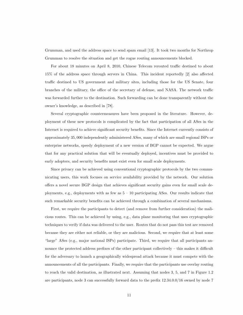
as illustrated in Figure 1.2. Here the address blocks 12.8.1.0/24 and 12.34.0.0/16 belong to nodes
5 and 7, respectively. Node 1 is malicious and announces the two address blocks that it does not
own. Some nodes will believe the malicious announcements and send traffic to the adversary. For
example, if node 3 sends traffic to an address in the address block 12.34.0.0/16, it will reach node
1 instead of the valid destination in node 7.
Incorrect prefixes can be announced with malicious intentions, as described above, or due to
misconfigurations. BGP attacks or misconfigurations have been occurring in the Internet with an
alarming frequency and spectacular consequences.
In February 2008 Pakistan Telecom brought down YouTube worldwide for several hours when
it tried to block local access to the service [50]. They mistakenly sent new routing information to
PCCW, an ISP in Hong Kong, that propagated the route further.
In May 2003, spammers hijacked an unused block of IP address space owned by Northrop
12.34.0.0/16
3 4
2
12.34.0.0/16
6
5
7
112.8.1.0 /24
12.8.1.0/24
Figure 1.2: Malicious node 1 announces address prefixes that it does not own. Some nodes willbelieve the malicious node and forward it the traffic addressed to the concerned prefixes.
10
Grumman, and used the address space to send spam email [13]. It took two months for Northrop
Grumman to resolve the situation and get the rogue routing announcements blocked.
For about 18 minutes on April 8, 2010, Chinese Telecom rerouted traffic destined to about
15% of the address space through servers in China. This incident reportedly [2] also affected
traffic destined to US government and military sites, including those for the US Senate, four
branches of the military, the office of the secretary of defense, and NASA. The network traffic
was forwarded further to the destination. Such forwarding can be done transparently without the
owner’s knowledge, as described in [78].
Several cryptographic countermeasures have been proposed in the literature. However, de-
ployment of these new protocols is complicated by the fact that participation of all ASes in the
Internet is required to achieve significant security benefits. Since the Internet currently consists of
approximately 35, 000 independently administered ASes, many of which are small regional ISPs or
enterprise networks, speedy deployment of a new version of BGP cannot be expected. We argue
that for any practical solution that will be eventually deployed, incentives must be provided to
early adopters, and security benefits must exist even for small scale deployments.
Since privacy can be achieved using conventional cryptographic protocols by the two commu-
nicating users, this work focuses on service availability provided by the network. Our solution
offers a novel secure BGP design that achieves significant security gains even for small scale de-
ployments, e.g., deployments with as few as 5 – 10 participating ASes. Our results indicate that
such remarkable security benefits can be achieved through a combination of several mechanisms.
First, we require the participants to detect (and remove from further consideration) the mali-
cious routes. This can be achieved by using, e.g., data plane monitoring that uses cryptographic
techniques to verify if data was delivered to the user. Routes that do not pass this test are removed
because they are either not reliable, or they are malicious. Second, we require that at least some
“large” ASes (e.g., major national ISPs) participate. Third, we require that all participants an-
nounce the protected address prefixes of the other participant collectively – this makes it difficult
for the adversary to launch a geographically widespread attack because it must compete with the
announcements of all the participants. Finally, we require that the participants use overlay routing
to reach the valid destination, as illustrated next. Assuming that nodes 3, 5, and 7 in Figure 1.2
are participants, node 3 can successfully forward data to the prefix 12.34.0.0/16 owned by node 7
11

by using the overlay to send the traffic first to node 5, which relays the traffic to node 7. Note that
node 3 can reach the intermediate node 5 by using any address in the address block 12.8.1.0/24.
In Chapter 3 we describe our solution in detail and evaluate its security benefits using simula-
tions. Our simulations rely on an accurate model of the Internet topology that was constructed by
inspecting routing tables of Internet routers. The simulations model the behavior of BGP routers
and simulate the impact of potential attacks.
1.2.3 Traffic Engineering after a Failure
Network operators need to carefully balance the load in the network in order to efficiently use
the existing link capacity. In addition, they need to handle planned equipment maintenance and
unplanned failures gracefully, without noticeable disruptions to the users. This challenging task
is further complicated by the fact that traffic patterns change significantly during the day, and
network operators need to satisfy strict service level agreements (SLAs) which specify, e.g., the
maximum average delay that the network traffic can experience.
Figure 1.3 illustrates the advantages and disadvantages of two possible techniques that can
be used to protect against failures – local path protection and global path protection. In local
path protection, the failure is repaired locally by sending the traffic on an alternate route between
the two endpoints of the failed link. The figure illustrates the disadvantage of this approach –
congestion in the neighborhood of the failure where the rerouted traffic shares a link with another
flow. Global path protection sends the traffic on an alternate end-to-end path, which allows to
s1
t1s2 t2
Figure 1.3: Two flows are shown by solid arrows. After a link failure, local path protection canbe used to reroute the affected traffic (top dashed arrow), or global path protection can be used(bottom dashed arrow).
12

spread the load in the network more evenly, but at the cost of re-optimizing the route selection to
minimize congestion. In practice, a combination of both techniques is used, local path protection
for its speed, and global path protection because it allows the network operator to re-optimize the
flow of traffic in the entire network according to the new conditions.
Our goal is to offer an alternative architecture to optimize load balancing under a wide range of
failure scenarios that does not require route re-optimization after a failure. In Chapter 4 we propose
to use an architecture that supports flexible splitting of traffic over multiple precomputed paths,
with efficient path-level failure detection and automatic load balancing over the remaining paths.
We systematically explore several possible load balancing algorithms that differ in their complexity
and the amount of state they need to store in the network routers. Since the more complex
solutions should allow better load balancing than their simpler counterparts, we explore this
tradeoff experimentally. To perform accurate simulations, we use traffic measurements, topology,
and failure data from a large ISP.
Our experiments allowed us to identify an architecture at the “sweet spot”, an architecture
that achieves near-optimal load balancing under a variety of failure scenarios with a relatively
small amount of state in the routers. Besides its simplicity and deployability of the solution using
current hardware, additional benefits include ability to use single configuration for traffic that
varies throughout the day, and ability to achieve network propagation delay similar to delays
experienced by routing algorithms that select paths to minimize this metric.
13

Chapter 2
Detecting Routing Protocol
Oscillations
2.1 Introduction
The Border Gateway Protocol (BGP) [92], the de facto interdomain routing protocol in the In-
ternet, offers autonomous systems (ASes) the flexibility to specify their custom routing policies.
Unfortunately, this flexibility may result in policy choices that cause persistent oscillations. Such
oscillations unnecessarily increase the number of BGP updates and negatively impact network
traffic. Over the past decade, researchers have developed a good understanding of which combi-
nations of routing policies lead to oscillations [23, 32, 37, 38, 43, 45, 86]. Most of these results were
based on an abstract model of the interdomain routing system — namely the Simple Path Vector
Protocol (SPVP) [44] — that captures how each node selects the highest-ranked path consistent
with its neighbors’ decisions.
This chapter shows that local engineering decisions, such as BGP timers and internal router
structures, can produce short-term artifacts that lead to protocol oscillations not well modeled by
SPVP. To capture how these local phenomena affect global convergence, we introduce an extension
of SPVP called the Dynamic Path Vector Protocol (DPVP). Although DPVP is seemingly more
complicated than SPVP, it actually yields to analysis more easily: we show that DPVP admits
14

a necessary and sufficient condition of convergence. Furthermore, we give an algorithm that for
most realistic settings efficiently determines whether a DPVP instance is safe, i.e., whether the
BGP system as modeled by DPVP converges.
2.1.1 Spurious Selection of Lower-Ranked Routes
Earlier studies of interdomain routing assume that routers select and announce the most-preferred
available route. However, routers in practice may temporarily announce other recently-available
routes, or even withdraw a route when the destination appears reachable. We call such unexpected
announcements and withdrawals spurious updates. These spurious updates can be caused by
several router-level mechanisms that delay the propagation of update messages (to reduce overhead
and improve stability) or limit visibility into the alternate routes (to improve scalability), including:
• Route flap damping [96]: Route flap damping temporarily suppresses a route if it appears
unstable. As a result, a router may temporarily select a less-preferred route.
• MRAI timers [81]: The Minimum Route Advertisement Interval (MRAI) timer paces
BGP update messages. Delaying message delivery can cause a router to temporarily select
a lower-ranked alternate route.
• Router queuing mechanisms: The BGP message queues between routers delay the deliv-
ery of updates. These queues, coupled with optimizations that stop generating new messages
when the queue grows large, can lead to delays in selecting the highest-ranked route.
• Cluster routers: Large routers are distributed,with BGP sessions terminating on different
processor blades. To improve scalability, these blades do not exchange full information with
each other, which may lead to a temporary selection of a less-preferred route.
• Proposed router extensions: Extensions to the BGP route-selection process were pro-
posed to improve router reliability [57] or to reduce convergence time [93]. This changes the
timing of routing decisions.
All spurious updates share two common properties: (i) a router can only send spurious updates
for a short time after receiving information changing its most preferred route, and (ii) spurious
updates are based on routes that have been recently available (including spurious withdrawals
15

because “no route” is always available). DPVP allows any spurious update with these properties.
We argue that such model is general enough to capture all spurious updates, but at the same time
we show that the model is not overly broad.
Just as local routing policies can affect global convergence [44], the local engineering decisions
that cause spurious updates can also trigger oscillations, and slow convergence exponentially.
Eliminating all sources of spurious updates would require major changes to router design and
the BGP protocol. Some of these mechanisms are important for reducing protocol overhead and
improving scalability, making it unappealing to eliminate them entirely. Protocol designers, router
designers, and network operators could strive to reduce the frequency and duration of spurious
updates. However, it is not clear that such a quest is warranted or plausible. Rather than
advocating for a world free of spurious updates, we argue for a better understanding of their
consequences.
2.1.2 DPVP Convergence
While allowing spurious updates shrinks the set of BGP configurations that are safe from oscilla-
tions, we establish that most of the well-studied situations deemed safe under SPVP remain safe
even under DPVP. In particular, we strengthen the SPVP-based results of [44] to show that even
DPVP is safe in a network without a “dispute wheel” structure. Thus, spurious updates do not
affect the large body of research on safety in dispute-wheel-free settings. In contrast, BGP safety in
more general settings, as well as convergence time, can be adversely affected by spurious updates,
as illustrated in Section 2.6.
Our main positive result on convergence that also demonstrates the power of DPVP is a
combinatorial necessary and sufficient characterization of safe DPVP instances, which is tractable
under most typical settings. We show that a DPVP instance is unsafe if and only if it admits a
certain combinatorial structure we call a “CoyOTE” (explained in Section 2.8). Although DPVP
adds the “complexity” of spurious updates over SPVP, this characterization is surprisingly nice in
several aspects that have been elusive for SPVP:
• Bijectivity: The absence of CoyOTEs is necessary and sufficient for safety. Prior work
has only yielded sufficient but not necessary [23, 37, 38, 43, 91], or necessary but not suf-
ficient [32, 86] conditions of convergence. Griffin et al.’s best-known result [44] shows the
16

absence of dispute wheels to be sufficient for safety. Also sufficient are the Gao-Rexford
conditions that constrain the network’s economic structure [38]. Cittadini et al. [23] derived
necessary and sufficient conditions for the stricter criterion of “safety under filtering” [32],
which requires convergence even if an arbitrary subset of routes are permanently filtered by
each router. However, those conditions are just sufficient but not necessary for safety under
a fixed filtering.
• Tractability in most common cases: Checking whether a network admits a CoyOTE
under general routing policies is NP-complete, just like the weaker question of checking
for the sufficient-only condition of No-Dispute-Wheel [44]. Luckily, we were able to find a
polynomial time algorithm that verifies safety of BGP configurations for virtually any policy
used by network operators in practice.
• Verifiability: Given a CoyOTE structure, one can easily verify its validity as a proof that a
network is unsafe. On a more theoretical note, this also places the formal problem of DPVP
safety in complexity class CoNP, relatively much easier than the PSPACE-complete problem
of checking safety in a comparable SPVP setting [30].
Roadmap: In Section 2.2 we review the Stable Path Problem (SPP), a general framework for
describing interdomain routing. In Section 2.3 we formally introduce our DPVP model of BGP
built on top of SPP that captures the effects of spurious updates on worst-case BGP convergence.
To demonstrate DPVP’s versatility and applicability, Section 2.4 describes a variety of real and
proposed router behaviors that could cause temporary announcements of lower-ranked routes, and
demonstrates global oscillations caused by these behaviors, yet not predicted by the classical SPVP
model of BGP. Section 2.5, conversely, establishes that DPVP is not over-broad: we show that any
sequence of events allowed by DPVP might indeed occur from combinations of the above causes.
Section 2.6 shows examples of theoretical results in the literature that, while correct under the
SPVP model, no longer hold in the presence of spurious updates. We show the No-Dispute-Wheel
DPVP safety condition in Section 2.7, and the necessary and sufficient condition for safety in
Section 2.8. Section 2.9 presents an algorithm for checking DPVP safety in polynomial time for
all “realistic” BGP policies. Finally, Section 2.10 shows that this “realistic policy” constraint is
necessary — allowing truly arbitrary policies makes it NP-complete to verify safety.
17

2.2 The Stable Paths Problem (SPP)
Here we review the Stable Paths Problem (SPP) due to Griffin et al. [45]. The reader familiar
with the SPP framework may proceed directly to Section 2.3.
The SPP [45] consists of a graph where each node represents a single BGP speaker, and a fixed
node which all other nodes try to reach. Each node has its own set of permitted paths to the origin,
and a ranking function that ranks the permitted paths in the order of preference. A solution of
the SPP is a global assignment of nodes to permitted paths such that each node is assigned the
highest ranked path that can be constructed based on the paths assigned at neighboring nodes.
The formal definition of SPP follows.
The simple undirected graph G = (V,E) with nodes V = {0, 1, 2, ..., n} represents the
network topology. Node 0 is the address origin and all other nodes try to establish a path to the
origin. Let neighbors(v) denote the neighbors of node v.
Paths are represented as a sequence of nodes (vk vk−1...v1v0) where for each k ≥ i > 0 we
have (vi, vi−1) ∈ E. An empty path is denoted ε. If two paths P and Q are not empty, and the
last node in P is the same as the first node in Q, the concatenation of the two paths is denoted
PQ. A subpath of the original path P = (vkvk−1...v1v0) from node vi to vj for some i > j is
P [vi, vj ], and P [vi] denotes a subpath from vi to the origin. We use v ∈ P to denote that node v
appears in path P .
The permitted paths to the origin are explicitly specified for each node. The set of permitted
paths for each v ∈ V is Pv. Any path P that appears in the set is permitted at the node v. P0
is well defined and contains the only valid path to the origin, i.e., the empty path ε. Let the
collection of all permitted paths be P = {Pv|v ∈ V }.
Route preference of each node v ∈ V is captured by its ranking function λv. If two paths
P1, P2 ∈ Pv and λv(P1) < λv(P2) then P2 is preferred to P1 by v. Let the collection of all ranking
functions be Λ = {λv|v ∈ V }.
Additional requirements pertain to the permitted paths and their ranking. For each λv
and Pv we require:
(i) Paths are simple: every non-empty path in Pv is a simple path from v to the origin.
(ii) Empty path permitted: Pv contains the empty path ε.
18

(iii) Empty path lowest ranked: λv(ε) < λv(P ) for all P ∈ Pv.
(iv) Strictness: if λv(P1) = λv(P2) then either P1 = P2 or the first edge of the two paths is the
same.
A path assignment is a function π that maps each node v to a path in Pv. π(v) = ε de-
notes that node v is not assigned a path to the origin. We write a path assignment as a vector
(P1, P2, ..., Pn) where π(v) = Pv, and the path of the origin to itself is omitted. Let choices(π, v)
be the set of all possible permitted paths at v that extend the paths assigned to their neighbors:
choices(π, v) =
{(v u)π(u)|(v, u) ∈ E} ∩ Pv v 6= 0
{ε} o.w.
Let W be a subset of permitted paths Pv such that each path has a distinct next hop. The best
path in W is:
best(W, v) =
P ∈W with maximal λv(P ) W 6= ∅
ε o.w.
The path assignment π is stable at node v if π(v) = best(choices(π, v), v).
The SPP specification is a triple S = (G,P,Λ) consisting of the graph, permitted paths,
and ranking functions. The specification S is solvable if there exists a stable path assignment π
for S, otherwise it is unsolvable.
2.3 DPVP: BGP Model with Spurious Updates
To study the dynamic properties of BGP, we introduce the Dynamic Path Vector Protocol (DPVP),
a formal model that allows transmission of stale information in spurious route updates. The
DPVP model specifies the dynamics of routing information exchange between routers in the SPP
framework. Section 2.3.1 informally explains how we model spurious updates. Then, Section 2.3.2
defines DPVP dynamics by specifying how a node exchanges routing information and selects a
preferred route. A convenient shorthand notation that provides a compact description of a dynamic
evolution of the DPVP model is introduced in Section 2.3.3.
19

2.3.1 Modeling the Spurious Updates
For a short period after receiving information that changes its best path, a router may temporarily
transmit stale information in the form of spurious route announcements or withdrawals. An upper
bound on the duration of the spurious behavior is required to prevent propagation of arbitrarily old
information. The DPVP model introduces a universal fixed constant τ1 that serves two purposes.
First, it limits the interval after a route change at node v during which stale information may
propagate from that node. Second, any stale information that propagates from node v at time t
must have been available at node v at some point in the time interval [t− τ, t].
Specifically, the constant τ serves as an upper bound on the communication delay caused by
queuing delays, the MRAI timer, the suppression period of route flap damping, and any other
source of spurious behaviors, current or future. Indeed, we deliberately do not model the specific
sources of spurious updates, so as to not limit our model to the sources thus far observed. Surely
other sources may be buried deep inside current router designs, or may arise in the future, and
we assert that modeling all of them with a generic finite cutoff is the right approach. That is,
we expect that any future design decision that violates this model (i.e., potentially sends spurious
updates indefinitely in an otherwise-stable system) would not be accepted by the network operator
community.
2.3.2 Dynamic Path Vector Protocol (DPVP)
The current time of a global clock is denoted by t.
The internal state maintained by each node v consists of the following. The assigned path
π(v) represents the most preferred route that is consistent with the information received by the
node at the present time. The structure rib-in(v ⇐ w) maintained by node v contains the most
recently processed information received from node w. The set recentRts(v) contains all routes that
node v has had recently available. This set includes any route that is available at the present time
t according to the information in the rib-in structure, as well as any route that was available in the
time interval [t− τ, t]. The state also includes variable stableTime(v) which determines stability of
the node as follows.
The stability of a node determines the properties of the information transfer from that
1Stability of an SPP instance in the DPVP model is independent of the actual numerical value of τ for 0 < τ <∞.
20

node. The node v is stable if t ≥ stableTime(v) and it is not stable otherwise. If a node v is stable,
any information transfer in the system concerning the assigned path π(v) must be accurate, i.e.,
the neighbors of node v learn the correct most recent route π(v). However, if a node is not stable,
then its neighbor may receive stale information consisting of any single path from recentRts(v).
The dynamic route information exchange is facilitated by edge activations. Simultaneous
edge activations are allowed. When the edge (w, v) activates, the process shown in Figure 2.1 is
executed. The “if” branch on lines 2–3 is executed if at the time of activation the node w is stable.
The rib-in(v ⇐ w) variable is updated with the most recent information from node w. If node w
is not stable, then lines 4–6 are executed, and node v learns information that is potentially stale.
Stale information either contains a route withdrawal, or announcement of some route recently
available at node w. The commands on lines 7–9 update the list of the recently available routes
recentRts(v). Newly available routes are added, and if a route becomes unavailable at time t, it
is scheduled for removal from recentRts(v) at time t + τ . Finally, the if statement on lines 10–12
determines whether the best route available to node v consistent with the information received
thus far changes. If the route changes then π(v) is updated accordingly and the node is marked
as unstable for a time period τ .
An edge activation sequence σ of sets (E0, E1, . . .) has Et containing the edges that are
activated at time t. An activation sequence is fair if each edge e ∈ E appears in the sequence
infinitely often, i.e., all node pairs continue exchanging routing information indefinitely.
activate(v ⇐ w)
1: old-rib-in := rib-in(v ⇐ w)2: if t ≥ stableTime(w) then3: rib-in(v ⇐ w) := (vw)π(w)4: else5: pick some P ∈ {recentRts(w) ∪ ε}6: rib-in(v ⇐ w) := (vw)P7: if rib-in(v ⇐ w) 6= old-rib-in then8: add rib-in(v ⇐ w) to recentRts(v)9: remove old-rib-in from recentRts(v) at time t+ τ
10: if π(v) 6= best(rib-in, v) then11: π(v) := best(rib-in, v)12: stableTime(v) := t+ τ
Figure 2.1: The DPVP model for router v responding to the activation of edge v ⇐ w, i.e. vprocessing information from w.
21

A vertex activation sequence ρ of sets (V0, V1, . . .) has Vt containing the vertices that
are activated at time t. When a vertex v activates, all its adjacent edges (w, v) ∈ E activate
simultaneously. We introduce vertex activations merely for convenience to allow more compact
notation.
DPVP is stable at time t if the path assignment π is stable and it has not changed in the
time interval [t − τ, t]. Note that if DPVP is stable, it is impossible for nodes to exchange stale
information, and the state cannot change at any later time.
DPVP is safe if any fair activation sequence, from any starting state, always converges to a
stable state. Note that safety in the DPVP model is independent of the numerical value of the
constant τ if 0 < τ < ∞ because the model does not limit the number of activations that can
occur during any time interval τ . We define safety under filtering in the same way as [23, 32] do.
DPVP is safe under filtering if it remains safe under removal of arbitrary subsets of paths from
an arbitrary subset of the Pvs (this generalizes the removal of arbitrary nodes and edges).
2.3.3 A Shorthand Notation
We introduce a shorthand state transition notation that concisely describes allowed oscillations
caused by spurious updates in the DPVP model. A systematic treatment of the causes and
consequences of spurious updates follows in Section 2.4.
An unsafe example of a network configuration is depicted in Figure 2.2. The network
contains three nodes which attempt to obtain a route to node 0. Each node is annotated with its
permitted paths, and these paths are listed in the order of decreasing preference. For example,
node 1 prefers the path 1230 over 10. To demonstrate that the configuration is unsafe, we must
find an oscillation, i.e, an initial path assignment, an activation sequence that activates every edge,
and possible spurious announcements that cause a cyclical change of the path assignment. As long
as the same activation sequence and spurious announcements are repeated, the oscillation persists.
The shorthand state transition notation that captures a possible oscillation in Figure 2.2
is as follows:
(10, 20, 30)2,3−−→ (10, 210, 30)
1;(1⇐2:230)−−−−−−−−→ (1230, 210, 30)2−→ (1230, 20, 30)
1−→ (10, 20, 30).
22

123010
21020230
30
230
2130
3
0
Figure 2.2: Example of an oscillation in DPVP. Node 2 exports a low ranked route 230.
The initial path assignment is (10, 20, 30), nodes 1, 2, and 3 have paths 10, 20, and 30 respectively.
The nodes or edges activated in each step are listed above the arrow. For example, the path
assignment (10, 210, 30) is reached from the initial state by activating nodes 2 and 3. If a spurious
announcement is made, this is also described above the arrow. For example,1;(1⇐2:230)−−−−−−−−→ represents
an activation of node 1 where node 1 learns about route 230 from its neighbor 2. The spurious
announcement of route 230 is allowed by the DPVP model because recentRts(2) contains route 230
and the path assignment of node 2 keeps changing during the outlined oscillation.
It is important to realize that not every shorthand notation that can be written down corre-
sponds to a valid evolution in the DPVP model. Consider for example the following:
(10, 210, 30)1,2,3;(1⇐2:230)−−−−−−−−−−→ (1230, 210, 30)
1−→ (10, 210, 30).
This notation is invalid because node 2, which is a stable node with a fixed path assignment 210,
cannot spuriously announce the low ranked route 230 in DPVP.
2.4 Expressiveness of DPVP
Having specified DPVP formally, we need to establish that it is a realistic model of BGP. We
discuss several key sources of spurious updates in BGP, and demonstrate how the DPVP model
captures them. These sources of spurious updates include (i) mechanisms that introduce
delays to improve stability and reduce overhead, e.g. route flap damping and MRAI timers, and
(ii) mechanisms that limit route visibility due to scalability requirements, e.g. specifics of
23

router implementations. While this list is necessarily non-exhaustive, DPVP is an abstract model,
and hence it is able to capture other sources of spurious updates as well.
We show specific examples of network configurations where the sources of spurious updates,
such as route flap damping or router architectures, cause persistent BGP oscillations. These
oscillations are correctly captured by the DPVP model, but the earlier established models of BGP
are usually not able to model them.
2.4.1 Route Flap Damping
The route flap damping mechanism is used to limit the propagation of unstable routes [96].
When it is enabled, a BGP router maintains a penalty associated with every prefix announced
by each BGP neighbor. Upon receiving a route update from a neighbor, the router increases
the penalty. If the penalty exceeds a given suppression threshold, the route is tagged when it is
inserted into the RIB. Tagged routes are not used in the route selection process, and a route with
a different next hop will be used. The penalties decay exponentially in time, and if a route doesn’t
change, its tag is eventually cleared and the route may be used. Next, we show how route flap
damping may cause spurious updates, which may in turn lead to permanent oscillations.
A spurious route announcement occurs when the route flap damping mechanism tem-
porarily suppresses a route that would otherwise be preferred. Consider Figure 2.3(a) where the
router R initially learns routes r2 and r3 from its neighbors A and B. The router announces
r1
Rr2r3 r3
BA C
r2→r1 r3
(a) After the update r2 → r1,the less preferred route r3 is tem-porarily selected.
13010
210202
0
1
3210
0
30321032030
3
(b) If node 3 suppresses routes from node 2,it must announce the route 30. This maycause oscillations.
Figure 2.3: The effects of route flap damping.
24

route r2 to router C. If the route r2 is updated to route r1, and the penalty associated with
BGP speaker A exceed the suppression threshold, router R temporarily suppresses route r1 and
selects and exports route r3. After the penalty decreases, route r1 is selected and exported. This
appears as a spurious announcement to router C. Route flap damping may also cause a spurious
withdrawal. For example, if router R was only connected to routers A and C, the same route
update would lead to a route withdrawal from router C. These spurious updates are allowed in
the DPVP model.
A permanent oscillation caused by route flap damping may occur in Figure 2.3(b). First,
we will convince ourselves that the configuration is safe in the absence of spurious updates: node
2 must choose either 210 or 20, and thus node 3 will choose either 3210 or 320. Therefore node 1
must choose 10 and the stable state is (10, 210, 3210). However, the following oscillation is possible
in DPVP:
(10, 20, 320)2−→ (10, 210, 320)
3−→ (10, 210, 3210)1;(1⇐3:30)−−−−−−−→
(130, 210, 3210)1,2−−→ (10, 20, 3210)
3−→ (10, 20, 320).
Indeed, this oscillation may occur due to route flap damping. Initially, node 2 activates and
changes its route from 20 to 210. When node 3 activates, it processes the route update from node
2, which triggers the route flap damping mechanism. Although node 3 enters the state 3210 in
DPVP, in the real BGP system the route 3210 is suppressed and the route 30 is used instead. This
explains why in the next activation the spurious announcement 30 is made, and the system enters
state (130, 210, 3210). Assuming that the damping penalty decreases, the subsequent activations
do not contain any spurious updates, and the system eventually enters the state it started in. This
example demonstrates that route flap damping may cause unexpected oscillations that are not
predicted by the earlier models of BGP.
2.4.2 MRAI Timer
The MRAI timer [80, 81] may also exhibit unexpected spurious updates. When a new route is
announced to a peer, subsequent route updates are postponed until the MRAI timer expires2. The
2The default value is 30 seconds in eBGP and 5 second in iBGP. However, the values used in practice rangebetween 0 and 30 seconds.
25

MRAI timer is applied to route announcements and, depending on the implementation, may [81]
or may not [80] be applied to withdrawals. Some previous models of routing do not capture the
asynchrony caused by MRAI timers. One such example is a variant of the Simple Path Vector
Protocol (SPVP) with vertex activations [44, 46]. We show that when MRAI timers are used, an
AS may unexpectedly lose connectivity or select a route which would not be selected in the SPVP
model of routing. This may in turn lead to unexpected oscillations.
An unexpected spurious announcement caused by the MRAI timer is illustrated in Fig-
ure 2.4(a). The simplified variant of the SPVP model with node activations does not allow node
2 to select the route 24130. This can be explained as follows. Node 2 can only learn route 24130
after node 1 learns route 130, but then node 2 should select route 2130. However, the behavior
of real BGP with MRAI timers differs. Let’s assume that node 1 learns route 10 and exports it
to node 2. Then it learns route 130, but cannot export it to node 2 because the corresponding
MRAI timer has not expired yet. Then node 2 may select the route 24130 learned from node 4,
but cannot select route 2130 until the timer in node 1 expires. The announcement of route 24130
by node 2 is possible in our DPVP model as a spurious announcement. The SPVP model with
edge activations also allows this announcement.
A permanent oscillation caused by MRAI timers may occur in Figure 2.4(b). This gadget
originally appeared in [22] as Figure 3. They show that this gadget is safe in the SPVP model with
0
3
13010
130
213024130
4130
4
224130210
2
(a) Node 2 temporarily selectsroute 24130.
1301230
2130210
230
2132 0
240
123010
210240230
421043
324030
421040
4
0
(b) MRAI timer in node 2 may cause perma-nent oscillations.
Figure 2.4: The effects of MRAI timers.
26

node activations, but it may oscillate in SPVP with edge activations. We show that the gadget
may also oscillate as a result of node 2 using the MRAI timer. Indeed, our DPVP model allows
the following oscillation:
(1230, 240, 30, 4210)2−→ (1230, 230, 30, 4210)
3;(3⇐2:240)−−−−−−−−→ (1230, 230, 3240, 4210)
1;(1⇐2:240)−−−−−−−−→ (10, 230, 3240, 4210)2−→ (10, 210, 3240, 4210)
1,3,4;({1,3,4}⇐2:230)−−−−−−−−−−−−−−→
(1230, 210, 30, 40)2,4−−→ (1230, 240, 30, 4210).
Initially, node 2 activates and changes its route from 240 to 230. This route change prevents the
node from immediately announcing the new route 230 to its neighbors due to the MRAI timer.
Therefore, when nodes 3 and 1 activate in the next two rounds, they receive the stale route 240.
The MRAI timer is also invoked during the second to last round of activations when nodes 1, 3,
and 4 receive the stale route 230. In conclusion, MRAI timers may be responsible for spurious
announcements that cause permanent oscillations.
2.4.3 Lack of Route Visibility
Oscillations can be also caused by spurious updates resulting from a temporary loss of route
visibility. We describe such losses of visibility due to the increasingly popular cluster-based router
architectures.
Distributed cluster-based routers parallelize functionality across multiple cores and across
multiple server blades within each router [4,27]. These architectures are becoming more common
due to the need to scale to larger port densities and traffic demands at a reasonable cost. A router
consists of multiple control processor blades, each handling a subset of the BGP sessions. Each
blade runs its own software and exchanges reachability information with other blades. While the
details of this information exchange differ from one implementation to another, scalability requires
each processor blade to usually only announce the currently used route (the best route) to the
other blades. Due to asynchrony, a blade may be temporarily unable to see a more preferred route
learned by some other blade. This may lead to spurious updates being sent.
A spurious route announcement due to loss of visibility may occur, for example, after the
most preferred route is withdrawn, and the second best route is not visible. Consider the example
27

in Figure 2.5(a) which consists of two communicating processor blades. The cluster-based router
prefers route r1 to r2 which is still more preferred than r3. When all three routes are available,
blade B selects route r1 and announces it to the other blade A. If route r1 is withdrawn, blade
B must temporarily select route r3 while it waits to learn about route r2 from the other blade.
Therefore, blade B spuriously announces route r3 to other external BGP speakers. A spurious
withdrawal can be caused if both routes r1 and r3 are withdrawn simultaneously. In such a case
blade B must withdraw the route r1 from its external BGP neighbor until it learns a valid route
from the other blade.
A permanent oscillation due to temporary lack of route visibility may occur in Figure 2.5(b).
First, we observe that if no router sends spurious updates, the configuration is safe. This is the
same configuration as in Figure 2.3(b) and hence the stable state must be (10, 210, 3210). However,
the following oscillation is allowed in DPVP:
(130, 210, 3210)2−→ (130, 20, 3210)
1,3;(3⇐2:ε)−−−−−−−→ (10, 20, 30)2−→ (10, 210, 30)
1,3−−→ (130, 210, 3210).
In the second round of activations, node 3 receives a spurious withdrawal from node 2. This is
explained as follows. Initially, node 2 was in state 210 and blade B used and exported the route
210. However, after node 1 switched to state 130, the route 210 was implicitly withdrawn, and
r1r2r3
A B
r2 r1 r3
(a) After route r1 is withdrawn,blade B temporarily announcesr3.
2102020 2
A1 B
13010
ε
A
0
32103203
30
(b) The temporary lack of visibility of route20 by processor blade B causes permanentoscillation.
Figure 2.5: The internal architecture of routers (or ASes) is a cause of spurious updates.
28
blade B was temporarily left without a route. Before blade B learned about route 20 from the
other blade, it sent a spurious withdrawal to node 3. Once again, this example demonstrates that
spurious updates may cause unexpected oscillations.
This chapter focuses on applying the DPVP model to model the router-level structure of the
Internet. However, DPVP may also be used to model entire ASes as nodes, if the policies of routers
inside an AS are consistent. This model is much coarser, and abstracts away many relevant intra-
AS details, but is often reasonable since, from an external viewpoint, there is often very limited
information about intra-AS router structure. In such a scenario, the internal structure of an
AS may cause spurious updates, as well. The situation is analogous to the one with cluster based
routers, individual routers correspond to processor blades and the communication of these routers
is facilitated by route reflectors [12]. A subset of routers is assigned to each route reflector, which
exchanges routing information with these routers and with other reflectors. Each router only
learns one best route from each of its route reflectors, hence causing similar loss of visibility as we
observed with cluster-based routers. This loss of visibility can be modeled by earlier BGP models,
such as SPVP, if the internal structure of each AS is known, and each router and route reflector
is represented as a separate node; on the other hand, DPVP allows us to consider questions of
safety while remaining agnostic about the ASes’ internal structures.
2.4.4 Router Queues
Unlike the classical SPVP model [45], DPVP does not explicitly model queues of BGP updates at
each edge endpoint. However, the DPVP model captures any behavior that a queue could produce.
If a node in the SPVP model processes a particular message from its queue that is older than the
most recent update from the same sender, it may be modeled in DPVP as a spurious update. If a
message is dropped from the queue, this may be modeled as a DPVP spurious withdrawal. On the
other hand, DPVP intentionally allows a more varied behavior than per-edge queues do. While
features like route flap damping may be modeled by particular patterns of dropped messages in
a queue, some patterns of spurious updates valid in DPVP will not correspond to any possible
queue behavior. It is worth noting that an edge in DPVP does not necessarily model a single BGP
session, but rather models all BGP messages that may be exchanged between two potentially large,
complex, distributed modern routers, which may share multiple physical links for redundancy, or
29

might even have several BGP sessions. Since much is unknown in the public domain about the
details of bleeding-edge intra-router architectures that vendors use today or may use in the near
future, we intentionally limit our assumptions about exactly how two DPVP nodes will interact.
We only assume the bare minimum restriction that we expect all routers to obey: the router acts
on some reasonable timescale consistently like a monolithic BGP speaker, independently of its
internal complexities.
Of course, if a DPVP instance is used to model AS-level behavior, there are many more possible
sources of spurious updates from inter-router interaction. Those spurious events would not be well
represented at all by any model involving a queue assigned to a node representing a whole AS.
2.4.5 Experimental Architectures
New router architecture proposals that aim to improve convergence or other properties of
the routing system by changing the route selection algorithm also introduce spurious updates. For
example, [57] builds a bug-tolerant router that runs multiple diverse copies of router software in
parallel and uses voting to select the correct route. They achieve diversity by varying the ordering
and timing of routing messages, and spurious inconsistencies in the decisions made by different
virtual routers may cause spurious updates. Another example is [93] which uses heuristics to
group BGP updates into priority classes to speed up convergence. Higher-priority updates are
processed and propagated sooner, while lower-priority ones are delayed. Using examples similar
as the ones in the previous subsections, it is easy to demonstrate that these mechanisms can also
cause permanent oscillations. These oscillations are again accurately modeled by DPVP.
2.5 All Spurious Updates can be Realized
We demonstrate that any spurious behavior that is allowed in the DPVP model can be realized
in the real interdomain routing system. Since we focus on the most general cases, our examples
necessarily rely on complex configurations. We note, however, that the examples in Section 2.4
show that many spurious updates in the DPVP model are caused by much simpler configurations.
In general, we need to show that when the most preferred path available to a router changes
from r1 to r2, the router may spuriously announce an arbitrary sequence of route updates r3, r4, r5, ...
30

r1 > {r3, r4, r5, …}r2 > {r3, r4, r5, …}
A B C D
r3
r3r4
r4r5
r5r3 r4 r5
Figure 2.6: If blade A damps route r2 after the update r1 → r2, blades B, C and D announceroutes r3, r4, and r5 after they learn about the loss of route r1.
to some neighbors before making the final announcement r2. For full generality, we need to sepa-
rately consider the two possible causes of the change of the most preferred route from r1 to r2. In
the first, an update with route r2 implicitly withdraws route r1. In the second, route r2 becomes
available in addition to route r1. We analyze the two cases separately.
The first case is illustrated in Figure 2.6 that depicts a cluster-based router consisting of four
processor blades. The blade A receives an update with route r2, which implicitly withdraws route
r1. Let us assume that this update triggers the route flap damping mechanism [96], and route
r2 is temporarily suppressed. Therefore, the router blade A announces to the other blades that
no route is available to it. This information first reaches blade B, which identifies route r3 as
the currently best route that is available to it, and announces it to its external BGP neighbors.
Similarly, blades C and D spuriously announce routes r4 and r5 after they hear from blade A.
Assuming that the route flap damping ceases, and the internal state of the cluster-based router
becomes consistent before further announcements are made, the final route r2 is announced next.
We conclude our analysis by noting that some of the routes r3, r4, r5, ... can be the empty routes
ε, and hence spurious withdrawals can be made.
Figure 2.7 illustrates the remaining case where a new route r2 becomes available in addition to
a less preferred route r1 which remains available as well. This example relies on the use of the Multi
Exit Discriminator (MED). If one or more routers in an AS learn multiple routes from the same
BGP speaker, these routes may be tagged with MED values. Routes tagged with smaller MED
values are strictly preferred over routes with higher MED values. In our example in Figure 2.7,
31

r2 > r1 > {r3, r4, r5, …}
A B C D
r3
r3r4
r4r5
r5r1 r3 r4 r5
Figure 2.7: Route r2 becomes available (numbers in parentheses are MEDs). If a small asynchronycauses damping in blades B, C, and D only, then these blades announce routes r3, r4, and r5respectively.
route r2 has its MED values shown in parentheses. Route r2 is announced to multiple blades on
multiple interfaces perhaps because multiple parallel links connect the cluster-based router to the
next hop on route r2. This is a common occurrence in practice because high speed connections
often consist of many parallel lower speed links. The link serviced by blade A has a higher MED
value than the other ones, perhaps because it is a backup link, or because the network operator
decided that the link needs to be taken down for maintenance in the near future, and traffic needs
to be diverted.
The following dynamics in the system in Figure 2.7 leads to the desired spurious behavior.
Initially, route r1 is announced to the outside by each blade. Because each blade is running its
own copy of the routing software, the blades must independently decide if an externally learned
route should be damped. The timing of message processing may cause a slight asynchrony where
one blade allows a route, whereas it is damped by another blade. Here we will assume that blades
B, C, and D damp the newly learned route r2 while blade A allows it. Therefore, blades B, C,
and D will learn that blade A would like to use route r2 (which should not be used due to its
MED), and therefore they will export the spurious routes r3, r4, and r5 similarly as in the previous
example. After the internal state of the cluster-based router becomes consistent, the final route
r2 is announced.
32

2.6 Impact on Convergence
After having established that spurious updates may cause permanent oscillations in configurations
that are otherwise stable, it is natural to ask if any existing results concerning convergence of BGP
change with the introduction of spurious updates. We show in Section 2.6.1 that an exponential
slowdown in convergence time may occur. Furthermore, in Section 2.6.2 we show an example of
safety conditions in the literature that ensure safety in the absence of spurious updates, but that
no longer hold in their presence.
2.6.1 Slower than Expected Convergence
Understanding and improving the convergence time [46, 73] has been a central question in the
BGP literature. It has been established that while the lower bound on convergence is in general
exponential [31], a more favorable bound can be obtained in a Gao-Rexford [38] model of routing.
In the Gao-Rexford model, every pair of neighboring ASes has a customer-provider relationship
or a peering relationship, and no AS can become an indirect provider of itself. Furthermore, every
AS prefers customer routes over peer or provider routes.
A recent paper of Sami et al. [86] shows that in the Gao-Rexford setting, the convergence time
of BGP is linear in the depth of the customer-provider hierarchy, or more precisely it is at most
2l+2 phases where l is the length of the longest directed customer-provider chain in the AS graph.
We define the term phase below. We show an example of a network that, when spurious messages
are allowed, the convergence takes (2k+ 1)l−2 phases where k is the number of spurious messages
that a node is allowed to announce after each route change. Our example, which is based on a
topology that appears in the original work of Sami et al. [86], shows that spurious updates may
cause an exponential slowdown of convergence even in the Gao-Rexford setting.
In their work a phase is defined as a period of time in which all nodes get at least one update
message from each neighboring node, and all nodes are activated at least once after receiving
updates from their neighbors. When a node activates, it processes the messages it previously
received from all of its neighbors. The example which we describe next demonstrates that because
the model of Sami et al. does not capture spurious route updates, it may lead to overly optimistic
conclusions.
33

Figure 2.8(a) depicts a network with l nodes. Node 1 prefers route 10, and every other node
i prefers route i(i− 1)0 over the direct route i0. These path preferences satisfy the Gao-Rexford
constraints if node 0 is a customer of every other node and node i− 1 is a customer of node i for
2 ≤ i ≤ l− 1. The length of the longest directed customer-provider chain 0, 1, 2, ..., l− 1 is l. The
arrows in the figure describe the initial routing choice of each node. Node 1 chooses the empty
route, the even numbered nodes route directly to the origin 0, and all odd numbered nodes except
node 1 route through the counter-clockwise neighbor. Except for node 1, the state is stable.
To show that the convergence in Figure 2.8(a) may take at least (2k+ 1)l−2 phases in a model
where each node is allowed to make at most k spurious updates after each route change, we first
analyze the convergence of the smaller topology in Figure 2.8(b). The smaller topology is a special
case of the larger one with l = 3, and we will show convergence in (2k+ 2) phases. In each phase,
each node must activate at least once. Spurious updates are only used when we explicitly mention
them. The initial state is (ε, 20). We assume that the two nodes activate simultaneously. After
the first phase the state is (10, 20), and after the second phase (10, 210). In the third phase node
1 spuriously withdraws the route from node 2. The system reaches state (10, 20) after the third
phase, and state (10, 210) after the fourth. This sequence is repeated, node 1 sends spurious
updates in every odd phase for a total of k spurious updates, and the state flips back and forth
between (10, 20) and (10, 210). The kth spurious update is made in phase 2k + 1 and the final
state is reached in phase 2k+ 2. Note that the route of node 1 changed once from ε to 10, but the
route of node 2 changed 2k + 1 times.
1021020
32030
43040
54050
0
21
3
5l‐1
4
(a)
10
1
0
21020
2
(b)
Figure 2.8: Slowly converging network configurations.
34

A slow convergence in Figure 2.8(a) is achieved with the following timing of spurious updates.
When the route of node i where 1 ≤ i ≤ l− 1 changes, this node makes a spurious announcement
of the previously chosen route after each of the nodes with a higher node number sent k spurious
updates and these nodes reached a stable state. Using the fact that in Figure 2.8(b) the state of
node 2 changes 2k + 1 times, we conclude that whenever the route chosen by node i changes, the
route chosen by node i + 1 changes 2k + 1 times. Therefore, the route chosen by node l − 1 will
change (2k + 1)l−2 times and the number of phases required for convergence is (2k + 1)l−2.
2.6.2 BGP Without a Reel Unsafe
Although BGP convergence without spurious updates has been studied extensively, prior work
either concerns sufficient or necessary conditions for safety. A classical result shows that the
absence of a structure called a dispute wheel3 is sufficient for safety [45]. Safety is also guaranteed
when routing policies satisfy the conditions of Gao and Rexford [38].
The strongest result concerning BGP safety prior to this work was by Cittadini et al. [23]. They
provide the necessary and sufficient conditions for safety with route filtering. Filtering allows each
node to remove an arbitrary subset of paths from the list of permitted paths. They prove that
instances that do not contain a dispute reel [23] are safe under any filtering, and if an instance
contains a dispute reel, then there exists a filtering that allows oscillations. Note that these
conditions become sufficient conditions for safety in the general setting without filtering. The
dispute reel result no longer holds if we allow spurious updates.
Consider the example in Figure 2.9. This is the same topology that appears as Figure 4 in the
original work of Cittadini [23] as an example of a safe topology without a reel (the dispute wheel
with pivot vertices 1, 2, and 3 is not a reel because each pivot vertex appears in three rim paths,
violating Definition 2.7.2). However, the following oscillation may occur:
(10, 20, 30)1,2,3;(2⇐1:130),(3⇐2:210),(1⇐3:320)−−−−−−−−−−−−−−−−−−−−−−−−→ (1320, 2130,
3210)1,2,3−−−→ (10, 20, 30).
This is a valid oscillation in the DPVP model where the spurious announcements may be
3Dispute wheel and dispute reel are formally specified in Definitions 2.7.1 and 2.7.2.
35

132010
3210320
3110130
30320
130
3
0
1
2130
210
2 213020210
2
Figure 2.9: The graph does not contain a reel. However, spurious updates may cause oscillations.
caused, e.g., by the details of cluster-based hardware implementation of routers 1, 2, and 3. To
make a spurious announcement, router 1 needs to have one router blade responsible for the BGP
session with router 0, and another blade responsible for the other two BGP sessions. Routers 2
and 3 could use similar hardware architecture.
2.7 BGP Safety with Spurious Updates
The unexpected oscillations due to spurious updates beg the question of whether previous results
on BGP safety continue to hold under the DPVP model. Fortunately, in Section 2.7.1 we are
able to extend the well-studied No-Dispute-Wheel condition [45], sufficient for BGP safety in the
SPVP model, to show that it is still sufficient for safety even with spurious updates. This result
implies that the class of systems that oscillate due to spurious updates is relatively small, and most
importantly, earlier results that use the absence of dispute wheel as a condition of safety hold even
in the presence of spurious updates. While Section 2.6.2 showed that the absence of dispute reels is
not sufficient for safety under filtering with spurious updates, Section 2.7.2 introduces a modified
structure, a two-third reel, which we show to be necessary and sufficient under filtering.
2.7.1 No Dispute Wheel Implies Safety
The classical result by Griffin et al. [45] shows that BGP is safe in the SPVP model in the absence
of dispute wheels, like the one in Figure 2.10, formally defined as follows:
36

Definition 2.7.1. [45] A dispute wheel W = (U,Q,R) of size k is a set of nodes U = {u0, u1, ..., uk−1}
and sets of paths Q = {Q0, Q1, ..., Qk−1} and R = {R0, R1, ..., Rk−1} such that the following con-
ditions hold. For each 0 ≤ i ≤ k − 1, when all subscripts are interpreted modulo k:
(i) Qi is a path from ui to the origin.
(ii) Ri is a path from ui to ui+1.
(iii) Qi ∈ Pui and RiQi+1 ∈ Pui .
(iv) λui(Qi) ≤ λui(RiQi+1).
Qk‐1
Q0
Q1
Qi+1 Qi
Rk‐1 R0
Ri
u1
0
u0
uiui+1
uk‐1
Figure 2.10: A dispute wheel of size k.
We strengthen Griffin et al.’s result to show that even with spurious updates, modeled by
DPVP, BGP is still safe if there is no dispute wheel. This automatically strengthens the appli-
cability of the large body of BGP literature that relies on the original No-Dispute-Wheel result
under SPVP. We show:
Theorem 2.7.1. DPVP instance with no dispute wheel is safe.
We note that although the absence of a dispute wheel is sufficient for safety, it is not necessary
in both DPVP and SPVP. That is, dispute wheels can occur in safe instances of the routing
problem.
Rather than prove Theorem 2.7.1 separately, we actually derive it as a corollary of the stronger
result in Section 2.7.2.
37

2.7.2 Safety with Filtering
Safety under filtering [32] studies convergence where an arbitrary subset of routes may be removed
from the set of permitted paths Pv. In [23] it was shown that the necessary and sufficient condition
for safety under filtering in the classical SPVP model is the absence of a particular type of dispute
wheel called a dispute reel :
Definition 2.7.2. [23] A dispute reel is a dispute wheel which satisfies the following conditions:
(i) Pivot vertices appear in exactly three paths: for each ui ∈ U , ui only appears in paths
Qi, Ri and Ri−1.
(ii) Spoke and rim paths do not intersect: for each u 6∈ U , if u ∈ Qi for some i, then no j
exists such that u ∈ Rj .
(iii) Spoke paths form a tree: for each distinct Qi, Qj ∈ Q, if v ∈ Qi∩Qj , then Qi[v] = Qj [v].
Section 2.6.2 showed that this result does not hold when we account for spurious updates. We
define a generalized version of the dispute reel structure, which we prove to be exactly what is
needed to identify the systems that are unsafe, but only due to spurious updates. That is, we
prove:
Theorem 2.7.2. BGP, as modeled by DPVP, is safe under filtering if and only if the network
has no “two-third reel”:
Definition 2.7.3. A two-third reel is a dispute wheel which satisfies the second and third condition
of dispute reel:
(i) Spoke and rim paths do not intersect: for each u 6∈ U , if u ∈ Qi for some i, then no j
exists such that u ∈ Rj .
(ii) Spoke paths form a tree: for each distinct Qi, Qj ∈ Q, if v ∈ Qi∩Qj , then Qi[v] = Qj [v].
The intuition for removing the first condition in the dispute reel definition is that spurious
behavior of DPVP effectively allows us to “mangle” the rim of the reel, with pivots appearing in
multiple rim paths. This would prevent divergence in SPVP, since a pivot would have to stick
to one of its options in between its activations, preventing its participation in other pivots’ rim
38

paths. However, with spurious announcements, the pivot may keep spuriously announcing some
of its other available routes in such a pattern as to keep the oscillation going.
Proof of Theorem 2.7.2: The theorem combines the two implication directions treated
separately by Lemma 2.7.1 and Lemma 2.7.2. �
Lemma 2.7.1. If a DPVP instance S is unsafe under filtering, it has a two-third reel.
Lemma 2.7.2. If a DPVP instance S contains a two-third reel, it is not safe under filtering.
We should first formalize the concept of a DPVP evaluation cycle, which, given that the
system is finite, will arise in any unsafe instance. An evaluation cycle C = (Π,M, σ) consists of
a path assignment cycle Π = π1σ1(M1)−−−−−→ π2
σ2(M2)−−−−−→ ...σk(Mk)−−−−−→ πk+1, with π1 = πk+1, with a
matching edge activation sequence σ and spurious message sequence M . A cycle is well-formed if
all the paths can evolve as specified given the message sequence, and the message sequence can
continue to be sent indefinitely. That is, no spurious announcements depend on any events that
predate the cycle; and every node sending messages changes its chosen path at least once in the
cycle, allowing it to keep sending spurious updates, as long as the cycle loops within τ time.
Let the set values(C, u) be the paths that node u adopts at some point in C. Let F be the set
of fixed nodes: those that have a fixed path assignment throughout C; and let G be the other,
oscillating, nodes. We will need this technical lemma:
Lemma 2.7.3. Suppose P ∈ Pv is adopted by node v ∈ G in the cycle C. Then we can write
P = QR where the first node on path R is in G and all other nodes further on in R are in F .
Proof. v ∈ G, and the destination 0 is in F . �
Proof of Lemma 2.7.1: We use proof techniques similar to the ones in the SPVP safety
proof [45] to show that an unsafe instance has a two-thirds reel.
Let C = (Π,M, σ) be a well-formed non-trivial cycle. Let U ⊆ G be the nodes that sometimes
adopt a path that consists of fixed nodes. U is nonempty, since there are oscillating nodes, and
applying Lemma 2.7.3 to one of them gives a node in U .
We now construct a dispute wheel. Let u0 be a node in U . Let Q0 = (u0, w0)Q′0 be the
path of u0 such that w0 ∈ F . Since any such w0 doesn’t send spurious updates in the cycle, one
can verify that there is only one such Q0, and it is the lowest ranked path in values(C, u0). Let
39

H0 ∈ values(C, u0) be the highest-rank path u0 ever adopts. We have λu0(H0) > λu0(Q0). Lemma
2.7.3 lets us decompose H0 = R0Q1, with Q1 = (u1, w1)Q′1, u1 ∈ U , and R0 being non-empty
since Q0 is unique at u0. We repeat this inductively to yield a sequence (ui), which loops back to
u0 since U is finite. The nodes ui, spokes Qi and rims Ri form the dispute wheel.
Finally, we prove that the dispute wheel also satisfies the two-third reel conditions of Defi-
nition 2.7.3. Suppose that condition (i) is not satisfied and there exists a node u ∈ Qi ∩ Rj .
Since u ∈ Qi, u and the rest of Qi[u] lie in F . Fixed nodes can’t send spurious updates, so any
repeating announcement of a path via u will end with Q[u] (by induction back from u to the
sender of the announcement). Thus, Rj [u] must be a prefix of Qi[u], requiring Rj [u] ⊆ F , but this
contradicts Rj [u] ending in uj+1 6∈ F . Suppose condition (ii) is violated, and there exist spoke
paths Qi, Qj ∈ Q and a node v ∈ Qi ∩ Qj such that Qi[v] 6= Qj [v]. Then v cannot be a stable
node, a contradiction.
Any instance that is unsafe under filtering will thus have a two thirds reel after some routes
are filtered. But if that subinstance has a two thirds reel, “unfiltering” those routes can’t remove
the reel, guaranteeing a two thirds reel in the original instance as well. �
Proof of Lemma 2.7.2: Given a two-thirds reel, we first find the right parts of the system
to filter out to cause the oscillation. We then define the path assignments that comprise the
oscillation, and finally we show the activation sequence that allows infinite transitions between
these path assignments.
Given an SPP instance S containing a dispute wheel W , the supporting instance S[W ] is the
minimal instance which contains the vertices, edges and paths of W . That is, the supporting
instance is obtained by filtering all paths except the spoke and rim paths in the dispute wheel,
and removing all edges and vertices outside of the dispute wheel.
The system oscillates by alternating between “all-spoke” and “one-rim” path assignments, like
those in Figure 2.11. Formally, an all-spoke path assignment is a path assignment π̄ such that
π̄(u) = Qi[u] if u ∈ Qi, and π̄(u) = ε otherwise. A one-rim path assignment is a path assignment
π̄i such that:
π̄i(u) =
Qj [u] if u ∈ Qj , u 6= ui
Ri[u]Qi+1 if u ∈ Ri
ε otherwise.
40

uRk‐1 R0u0
u1uk‐1
Q
Q0
0
Qk‐1 Q1
0
Qi+1 Qi
u
Ri
ui+1 ui
(a) All-spoke path assignment π̄.
uRk‐1 R0u0
u1uk‐1
Q
Q0
0
Qk‐1 Q1
0
Qi+1
Qi
u
Ri
ui+1 ui
(b) One-rim path assignment π̄i.
Figure 2.11: Special path assignments of a two-third reel.
Let S be the routing problem instance containing the two-third reel R = (U,Q,R) of size k.
We consider the supporting instance S[R] and construct a fair activation sequence with a sequence
of possibly spurious messages that cause oscillations. The main idea is to alternate between the
all-path assignment π̄, and one-rim path assignment π̄i. Once a one-rim path assignment π̄i is
reached, the all-paths assignment is reached next, followed by the one-path assignment π̄i+1. This
infinite sequence repeats itself, with the index i+ 1 calculated modulo k. The paths of the nodes
on the rim changes, and hence these nodes may send spurious updates.
The proof is illustrated in Figure 2.12. The black nodes are nodes that have a fixed path
throughout the evaluation cycle. The paths of the white nodes change and we assume that the
convergence time τ is long enough to allow these nodes to make spurious updates. Note that we
design the oscillation with the property that every rim node oscillates; the system may also have
other oscillations without this property.
We start with the empty state, π(v) = ε for all v. First, we activate the edges of each spoke
path Qi in outbound order from 0. Any non-pivot spoke node is not on the rim, and the pivots are
all on separate spokes, so the filtering causes the spokes to build up the all-spoke path assignment
π̄. In the remainder, we will assume that, unless stated otherwise, each node u ∈ Rj for each
j always sends a spurious withdrawal (ε) to every neighbor. All other nodes make non-spurious
announcements. Next we activate the edges on path R0 = (x0 = u0, x1, . . . , xl = u1) in reverse
order, i.e., starting from node u1. The node xi spuriously announces route R0[xi]Q1 to node xi−1.
41

u u02
R3
Q
R0
u3 u0
1. 1.2. 2.
3.Q0Q3
Q1Q2
1. 1.
2. 2.R
u1R2
3.3.u2
Figure 2.12: Sequence of activations that results in permanent oscillations.
Therefore, the path assignment π̄0 is reached. If all edges of each rim node are activated making the
spurious withdrawal as specified before, the all-spoke path assignment is reached again. Continuing
inductively, we reach assignment π̄1, and so on, yielding the infinite activation sequence. �
Proof of Theorem 2.7.1 is now a direct corollary of Theorem 2.7.2. If there is no dispute
wheel, there is no two-thirds reel, a special type of dispute wheel, and the resulting safety under
filtering implies safety. �
As should be evident from the ease with which we prove the sufficient conditions for safety
in the DPVP model, spurious updates give us extra flexibility when finding oscillations, which
makes proofs significantly easier. In the remainder of the chapter we solve the long-standing open
problem of finding the necessary and sufficient conditions for safety.
2.8 The Necessary and Sufficient Conditions
We now formulate a sufficient and necessary condition for safety in the DPVP model. We show that
a system is unsafe if and only if the configuration allows the existence of a particular combinatorial
structure in the network. Since such a structure can serve as an easy-to-check proof that the
system is unsafe in DPVP, the problem of deciding DPVP safety is in coNP, which contrasts the
intractability results that show SPVP safety checking is PSPACE-complete [30]. Most remarkably,
42

our results in Section 2.9 show that we can check a DPVP system for safety in polynomial time
in most practical settings.
Informally, the network will be unsafe if and only if it admits a mapping of each node to a
“selected path” and a partition of the nodes into two non-empty sets:
1. Stable nodes that in any infinite fair activation sequence eventually select a path consisting of
only stable nodes, and, combined with all stable nodes’ selected paths, comprise a consistent
routing tree to the destination.
2. Coy nodes that are “coy” about joining that stable tree: there exists an infinite fair activation
sequence in which they select a path that starts with another coy node as a next hop,
preferring it over any paths that go straight to the stable tree.
We will shortly formally define this complete structure — which we dub a CoyOTE (for
“Coy Optimum at Tree Edges”) — by a set of requirements on a node partitioning and a path
assignment that make one side of the partition “stable” and the other “coy”, as roughly sketched
above. We will show that, in a network that admits a CoyOTE structure, the stable nodes must
reach a stable state under any activation sequence, while the coy nodes are capable of triggering
DPVP oscillations.
Theorem 2.8.1. An instance of DPVP oscillates if and only if it has a CoyOTE.
To formally define the CoyOTE structure, we’ll need some intermediate technical definitions:
We use C ⊂ V to denote the set of coy nodes, and always define S = V \ C to denote the
complementary set of stable nodes. Given a path assignment Π and a coy set C, we define the
set stableChoices(v, C,Π) of all paths available to v that go directly to the stable set: all P ∈ Pv
such that P = (v, u)P ′ where u ∈ S and P ′ = πu. If the set stableChoices(v, C,Π) is nonempty, let
bestStable(v, C,Π) be the best such path: the unique P ∈ stableChoices(v, C,Π) for which λv(P ) is
maximal. Otherwise let bestStable(v, C,Π) be ε.
Definition 2.8.1. The pair (Π, C) of a path assignment Π and a coy set C ⊂ V (with the stable
set defined as S = V \ C) is a CoyOTE if the following conditions hold:
(i) Stable origin: The origin is stable, 0 ∈ S.
43

(ii) Coy existence: There are coy nodes, C 6= ∅.
(iii) Best stable path at stable node: A stable node is assigned its best stable path — for all
v ∈ S, πv = bestStable(v, C,Π).
(iv) Coy node prefers a coy path: a coy node is assigned a path learned from a coy node
— for all v ∈ C we have πv = (v, vnext, . . . , 0) with vnext ∈ C. The assigned route must be
higher ranked than v’s most preferred stable route, λv(πv) > λv(bestStable(v, C,Π)).
(v) Consistency with stable suffixes: Every node’s assigned path is “suffix-consistent” with
(S,Π), as defined below.
Definition 2.8.2. A path πv is suffix-consistent with (S,Π) if every suffix of πv that starts
with a node s ∈ S is consistent with πs: if πv = (v, . . . , s, Ps, 0) and s ∈ S (Ps is an arbitrary
subpath), then πs = (s, Ps, 0).
We will need the following easy corollary of the definition:
Lemma 2.8.1. In a CoyOTE:
(i) If v is stable (and πv 6= ε), then πv = (v, PSv , 0), where PSv is a possibly-ε subpath containing
only stable nodes.
(ii) If v is coy, then πv = (v, PCv , PSv , 0), where PCv is a non-empty subpath consisting of only
coy nodes, and PSv is a possibly-empty subpath consisting of only stable nodes.
Proof. By induction on the length of paths assigned by Π. Assuming a node chooses a path where
a coy node occurs after a stable node, by condition v there is a suffix (s, c, . . . , 0) with s ∈ S,
c ∈ C, but then πs violates condition iii. With condition iv, the rest follows inductively. �
We now tackle the two directions of Theorem 2.8.1 separately: Lemma 2.8.2 and Lemma 2.8.4
establish that a CoyOTE is sufficient and necessary, respectively, for oscillations in DPVP.
Lemma 2.8.2. If a DPVP instance has a CoyOTE, then the DPVP instance can oscillate.
Proof. Given a CoyOTE (C,Π), it suffices to find an infinite fair activation sequence in which the
state of the system continues changing.
44

Consider starting with an empty path assigned to each node (e.g., as if the destination just
went online). The activation sequence starts by every stable node v ∈ S with πv 6= ε activating
in the order of breadth-first search on the stable node tree, from the destination outward, so that
each such node gets its path in πv immediately, and never changes again.
After that, all the coy nodes v ∈ C activate in a loop so that each one chooses the path πv
at some point. Pick some order of coy nodes, c1...k. For each ci in order, we run 2 rounds of
activations. In round 1, activate all the coy nodes on the coy prefix of the path πci (nodes PCci in
Lemma 2.8.1), starting with the node at the edge of the stable tree and moving toward ci, and
have them announce, perhaps spuriously, their suffix of πci . By ci’s turn, πci will be available,
so it or another coy-next-hop path will get selected. Round 2 activates all the same nodes in the
same order, and has them send spurious withdrawals. With no coy-next-hop paths available after
that, ci will change its path selection. Repeat this sequence for all the cis in a loop. Each coy
node will keep changing its route, allowing it to keep sending spurious updates.
By condition iii, any stable node v with πv = ε cannot have any paths in Pv available from its
stable neighbors. Thus, it may only receive announcements of allowed paths from coy nodes. By
having these remaining stable nodes activate after the second round of each ci step above, they
will never have any allowed paths available to them. �
For the other direction, we need another technical lemma:
Lemma 2.8.3. Let an oscillating node c ∈ V in an instance of DPVP select path P at some point
during the oscillation. If the path P contains node s ∈ V and the node s does not oscillate, then
node s must permanently select path P [s, 0].
Proof. Oscillating nodes only announce recently available paths. Since s will not be announcing
spurious updates for longer than τ after it stops oscillating, any stale path containing node s and a
suffix other than P [s, 0] will not be announced anywhere for longer than iτ time after s converges
and enough fair activation phases pass. �
Lemma 2.8.4. If a DPVP instance oscillates, it has a CoyOTE.
Proof. Given the oscillating instance I and the corresponding activation sequence, we construct a
CoyOTE (C,Π).
45

Let SI be the non-oscillating nodes and CI the oscillating nodes in the instance I. Any non-
oscillating node v ∈ SI which permanently chooses path (v, u)P learned from an oscillating node
u ∈ CI can be made to oscillate by changing the activation sequence. Add an activation of the edge
(u, v) with a spurious withdrawal, and a second activation of the edge with a (possibly spurious)
announcement of path P . We keep adding nodes to CI until no more nodes can be made to
oscillate. We can set Π so that (CI ,Π) is a CoyOTE. For non-oscillating nodes v ∈ SI , we set πv
to be the path permanently chosen. For oscillating nodes v ∈ CI , we set πv be the highest ranked
of the path(s) that v chooses in the oscillation.
(CI ,Π) can be seen to be a CoyOTE: The origin is stable and CI is non-empty, yielding
conditions i and ii. After the above iteration, every node s remaining in SI has a path πs that
is either ε or was learned from another node in SI . Any path from s to a next hop also in SI
is continually available, so s chooses the stable path bestStable(s, C,Π) which must be available,
yielding condition iii. If, for v ∈ CI , the highest ranked path chosen infinitely often in the
oscillation has a stable next hop, then, after the next hop stabilizes and τ time passes, that path
must indeed become permanently available, which contradicts v continuing to oscillate, yielding
condition iv. Lastly, Lemma 2.8.3 covers condition v. �
2.9 Practical Algorithm for Safety Verification
We now consider the algorithmic question of checking safety under DPVP. We give an algorithm,
“DeCoy”, that greedily shrinks the candidate coy set, and reaches an empty coy set if and only if
there is no CoyOTE. This algorithm is always correct, but its runtime depends on the local policies
of the nodes. After analyzing the algorithm in general, we specify the large class of policies which
enable it to run efficiently, which turns out to cover most BGP policies used in practice.
2.9.1 The “DeCoy” safety verification algorithm
The DeCoy algorithm greedily builds up the candidate stable set, starting with just the destina-
tion4:
4And possibly some nodes that are permanently disconnected from the destination, which are stable and retainthe empty route.
46
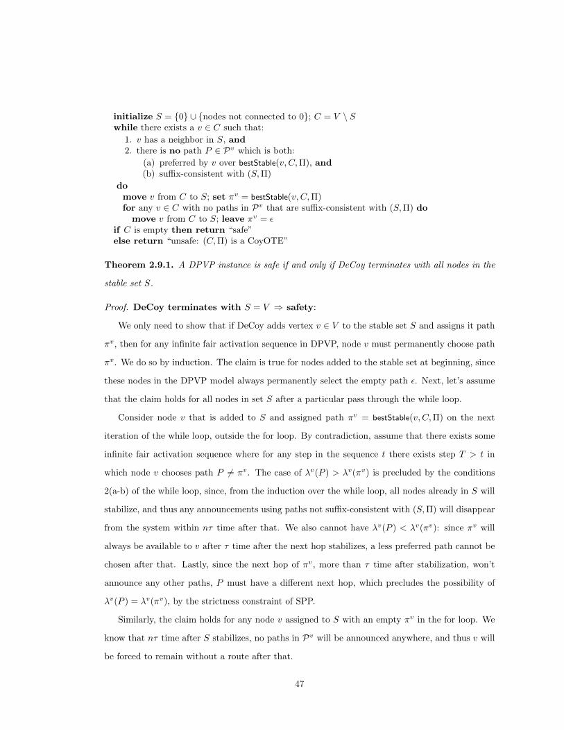
initialize S = {0} ∪ {nodes not connected to 0}; C = V \ Swhile there exists a v ∈ C such that:
1. v has a neighbor in S, and2. there is no path P ∈ Pv which is both:
(a) preferred by v over bestStable(v, C,Π), and(b) suffix-consistent with (S,Π)
domove v from C to S; set πv = bestStable(v, C,Π)for any v ∈ C with no paths in Pv that are suffix-consistent with (S,Π) do
move v from C to S; leave πv = εif C is empty then return “safe”else return “unsafe: (C,Π) is a CoyOTE”
Theorem 2.9.1. A DPVP instance is safe if and only if DeCoy terminates with all nodes in the
stable set S.
Proof. DeCoy terminates with S = V ⇒ safety:
We only need to show that if DeCoy adds vertex v ∈ V to the stable set S and assigns it path
πv, then for any infinite fair activation sequence in DPVP, node v must permanently choose path
πv. We do so by induction. The claim is true for nodes added to the stable set at beginning, since
these nodes in the DPVP model always permanently select the empty path ε. Next, let’s assume
that the claim holds for all nodes in set S after a particular pass through the while loop.
Consider node v that is added to S and assigned path πv = bestStable(v, C,Π) on the next
iteration of the while loop, outside the for loop. By contradiction, assume that there exists some
infinite fair activation sequence where for any step in the sequence t there exists step T > t in
which node v chooses path P 6= πv. The case of λv(P ) > λv(πv) is precluded by the conditions
2(a-b) of the while loop, since, from the induction over the while loop, all nodes already in S will
stabilize, and thus any announcements using paths not suffix-consistent with (S,Π) will disappear
from the system within nτ time after that. We also cannot have λv(P ) < λv(πv): since πv will
always be available to v after τ time after the next hop stabilizes, a less preferred path cannot be
chosen after that. Lastly, since the next hop of πv, more than τ time after stabilization, won’t
announce any other paths, P must have a different next hop, which precludes the possibility of
λv(P ) = λv(πv), by the strictness constraint of SPP.
Similarly, the claim holds for any node v assigned to S with an empty πv in the for loop. We
know that nτ time after S stabilizes, no paths in Pv will be announced anywhere, and thus v will
be forced to remain without a route after that.
47

DeCoy terminates with non-empty C ⇒ a CoyOTE exists:
Observe that after DeCoy finishes, the πv for every node v ∈ C is left unspecified. We complete
the specification of the path assignment Π by setting πv for every v ∈ C to the highest ranked path
in Pv that is suffix-consistent with (S,Π). This must be a non-empty path, ranked strictly higher
than bestStable(v, C,Π). Otherwise, if bestStable(v, C,Π) is non-empty and there is no such path,
v would satisfy the while loop’s condition and would be added to the stable set. Alternatively,
if the resulting πv is ε — or, equivalently, if bestStable(v, C,Π) is empty and there is no allowed
suffix-consistent path higher-ranked than ε — then there is no allowed suffix-consistent path at all.
In that case, v would have been stabilized inside the for loop after its last allowed path stopped
being suffix-consistent. This insures CoyOTE condition (iv).
CoyOTE conditions (i), (ii), (v) are immediate from the construction if C 6= ∅.
Note that throughout the algorithm, the set S grows, and path assignments are never changed
after being set for the first time. As more nodes are stabilized and the number of constraints
required for suffix-consistency increases, the set of candidate paths that are suffix-consistent with
(S,Π) monotonically shrinks.
For a stable node s with a non-empty path, consider the stable next hop s′ of the path
bestStable(s, C,Π), using the final values of C, S, and Π. Suppose s′ was added to the stable
set after s, so it would have been still in C when s was being added. Since πs′
was suffix-
consistent when it was assigned to s′, by monotonicity, it was suffix-consistent earlier, too. But,
since that path became bestStable(s, C,Π) by the end of the algorithm, it must have ranked higher
than whatever path s was assigned as its current bestStable(s, C,Π), using the running value of
C and Π when s was stabilized (when s′ wasn’t stable yet). Thus, s′’s path would have negated
condition (2) of the while loop, preventing s from being stabilized. Thus, s′ was stabilized before
s, and, by the time s was stabilized, we had bestStable(s, C,Π) = (s, πs′), confirming CoyOTE
condition (iii).
For a stable node s with an empty path, by the monotonic shrinking of the set of suffix-
consistent paths, if there were no allowed suffix-consistent paths when πs was assigned ε, none
would have appeared since, guaranteeing that bestStable(s, C,Π) would be ε at termination, too,
and confirming condition (iii) here, too. �
48

The efficiency of the DeCoy algorithm turns out to be intricately linked to the tractability of
optimizing over policies, including both router preferences (embodying, e.g., BGP local preference
settings), and allowed path sets (embodying, e.g., filtering rules). We first define the fully general
requirements on optimizable policies that allow DeCoy to run efficiently, and then, in Section 2.9.2,
discuss the wide range of realistic policies that fit into this framework.
Definition 2.9.1. We say that a node v implements optimizable policy if v’s permitted path
set Pv and ranking function λv allow this node to find, in polynomial time, the highest-ranked
path P ∈ Pv that is suffix-consistent with a given stable tree (S,Π) (which, being a tree, is itself
suffix-consistent).
Theorem 2.9.2. If all nodes implement optimizable policy, DeCoy runs in polynomial time.
Proof. We can search through the O(n) paths in stableChoices(v, C,Π) by brute force, to find the
bestStable path. The optimizable policy constraint then lets us check whether the most preferred
suffix-consistent allowed path is stable — which is needed to evaluate the second condition of the
while loop. The for loop condition is checked by seeing if the optimization returns the empty path
as the best suffix-consistent allowed path. The other steps are always efficient.
Nodes are stabilized at most once, so there are a total of at most |V | iterations involved in
both loops. Thus, even a brute-force implementation will finish in O(|V |f(n)2) time, where the
efficient policy evaluation runs in time f(n) as a function of the input. With most specific policies,
we expect the best runtime to be substantially faster. �
DeCoy is thus polynomial-time as long as a node’s policy lets it efficiently figure out “what
route do I most prefer, given what the rest of the world has permitted me?” We assert that
a policy which does not allow a tractable answer to this question is somewhat strange. In a
heuristic sense, that would entail the router “not knowing what is best for it”, even when shown
the full network structure and available paths, and instead awaiting whatever the notoriously
unpredictable network dynamics give it, with no easily-computable goal in mind.
2.9.2 Verifying Safety in Practice
We now present a broad range of realistic policies that turn out to be optimizable. The BGP
policies actually used by ASes are varied and complex, but fairly well understood [19]. Typically,
49

a router implements a decision process that first applies import policies to filter out some routes
received, then applies a local ranking to select the most preferred available route, and then applies
export policies to determine whom to announce it to.
For the purposes of DPVP analysis, we distinguish two types of policies: (1) preference
policies prefer some routes less than others, but don’t preclude spurious announcements of such
routes (modeled with the λ local ranking function); and (2) filtering policies which remove a
route at such an early point, or at such a low level of the router, precluding even spurious updates
involving that route (modeled with the permitted paths set Pv). BGP import/export constraints
will often be filtering policies. But BGP policies often thought of as filters, such as “avoidance
policies” (like “avoid paths through country X”) , are often actually just a depreferencing step in
the preference function, without any clear mechanism forbidding spurious announcements of such
a route.
Below, we present examples of common policies classified as either filters or preferences in a
particular way. But we prefer that the reader remains agnostic about what kinds of policies to file
under which of these two categories. This decision depends on the details of the mechanisms gener-
ating spurious updates or on the algorithm executor’s decision to seek a more conservative/robust
notion of safety: safety under a wider range of possible (mis)behaviors. Moving a policy from
“filtering” status to “preference” status can only allow more spurious update possibilities, yielding
a more robust notion of “safety”, which we think is natural to seek. Remarkably, in all the cases
we consider below, moving policies we consider as filtering policies to the preference stage would
keep all the policies efficient.
A filtering policy requires that a path not be used even in absence of any other options, so we
expect that each such black-and-white policy has a strong incentive behind it, typically produced
by economic or security constraints. In most typical scenarios, a non-stub AS is only likely to
filter based on some combination of the next and previous hop on the path in question (as needed,
e.g., for Gao-Rexford economic constraints [38]), and the destination of the packet (as needed for
blackholing, motivated by security or politics).
In particular, we admit as “typical filtering policies” any disjunction of polynomially many
filtering rules that filter paths that are:
(a) learned from neighbor u and announced to neighbor v, or
50

(b) learned from neighbor u, or
(c) announced to neighbor v, or
(d) violating Gao-Rexford constraints, or
(e) leading to a blacklisted destination.
Rule (a) is quite general and rules (b) through (d) can be implemented by applying rule (a)
polynomially many times.
This notably excludes filtering paths that go through another transit provider somewhere fur-
ther in the path, but not on the next hop. The latter type of filtering, for security or for censorship,
is unlikely to be effective, due to path diversity in the Internet.
Most preference policies observed in practice are covered by the following (in an arbitrary
order):
(i) split the space of paths into some polynomial number of “categories”, each of which disallows
the use of some subset of nodes and/or edges, and prefer “categories” in a particular order,
or penalize each category differently.
(ii) within each category, prefer routes based on a stratified shortest path metric with a logarith-
mic number of strata, and polynomially many preference levels within each stratum.
The inner category of stratified shortest path metrics, introduced by Griffin [42], allows a rich
space of preferences based on a general algebraic semi-ring structure that allows us to “lexicograph-
ically stack” several precedence levels of preference constraints that are algebraically isomorphic to
a shortest path problem. This allows many common policies beyond just basic shortest-hop-length.
For instance, such a policy can be as complicated as:
1. prefer customer routes; then
2. penalize paths passing through country X by px, and through countries Y and Z, by pyz;
then
3. pick a route using the shortest hop path;
4. of those routes, pick a route that that minimizes some linear combination of:
51
(a) number of “undesirable” nodes it passes (e.g. low-performing nodes)
(b) average data-plane packet loss rate over the path;
5. then pick the one w/the lexicographically 1st next hop.
The number of strata in this unusually complicated example is 4, and no more than a small
constant number of strata should ever be needed for realistic policies. Indeed, Griffin’s work on
such policies in [42] restricts the consideration to ≤ 3-stratum policies.
The outer splitting of policies into categories with disallowed nodes/edges allows a yet wider
range of policies that don’t fit neatly into the stratified shortest path framework. E.g., it allows
a fixed penalty for path visiting some set of nodes (rather than counting how many nodes are
visited), or it allows any route going through some next-hops (e.g. Gao-Rexford customers) to be
strictly preferred over other next-hops (Gao-Rexford providers). This in particular allows the full
implementation of any Gao-Rexford business policies, in addition to complex stratified shortest
path policies within each business relationship class. The only meaningful restriction that we know
of is that the number of categories be polynomial. If there is a list of more than a logarithmic
number of “bonuses”, each assigning an additive penalty to a path with a particular non-stratified-
shortest-path-based feature, that would generate a superpolynomial number of categories. While
such a policy could be implemented with using common router policy description languages, it is
not clear that operators would do so, since it creates an extremely fine-grained distinction between
superpolynomially many combinations of bonuses, which seems unnecessary in any context we
know of. Together, these two levels of preference policy correspond closely to the decision processes
described in [19].
Theorem 2.9.3. Any combination of “typical” filtering and preference policy classes above con-
stitutes optimizable policy.
Proof. We need to demonstrate a polynomial-time algorithm to find a node’s most preferred suffix-
consistent path that would not be filtered by the nodes on it.
We start by modifying the graph to ensure suffix-consistency and compliance with filtering
policies, and then run a modified version of the Bellman-Ford algorithm, applied separately to
each of the polynomially many categories of the preference policy.
52

To ensure suffix-consistency with stable set S, convert into one-way edges (1) all edges from
V \S to S, in that direction; and (2) the edges of the routing tree, formed by the (suffix-consistent)
path assignments of stable nodes with non-empty paths toward d. Then remove edges between
two stable nodes that are not used in the routing tree. Any permitted path that is consistent with
these changes is suffix-consistent, since once it hits a stable node, it can do nothing but follow the
stable tree to the destination.
Then remove any nodes that filter paths to the destination in question.
Then, separately for each category of the preference function, remove the disallowed edges or
nodes from the network graph.
We then set a function λv by transforming each stratum of the stratified-shortest-path pref-
erences into the isomorphic shortest path problem, and combining all the strata into a single
preference value that follows the lexicographic ordering. For example, a 2-stratum policy with top
stratum ranging from 1 to 9, and a second stratum ranging from 1 to 99 would be combined into
a λv ranging from 101 to 999, with the first digit corresponding to the first stratum, and the last
two digits corresponding to the second stratum. The combined λv still has a polynomial range,
due to the constraints on the strata.
We then run a Bellman-Ford variant to compute paths to destination minimizing λv. The only
additional constraint is that we must account for node filtering policies, which we do at each node
as the Bellman-Ford wavefront propagates. Specifically, we maintain not just the shortest path at
each node, but rather each node tracks for each next-hop-and-previous-hop pair (u, v) separately
the shortest path that can be imported from u and exported to v.
The correctness argument follows from Bellman-Ford. The runtime scales linearly with the
complexity of the preference policy evaluation, and increases only polynomially from maintaining
shortest path options for each (u, v). �
2.10 Hardness of Some Safety Verification Formulations
We will prove that in the most general settings it is NP complete to verify whether a DPVP instance
is safe. The intractability relies on route preferences that are typically not used in practice, such
as preference for longer routes over shorter ones, preference for routes of a particular fixed length,
or filtering policies applied to transit traffic.
53

BGP permits the use of regular expressions to specify routing policies. In order to show that
verifying the safety of BGP becomes NP complete when regular expressions are used to make the
problem inputs (which include routing policies) more compact, we define regular expressions that
are allowed to contain the ”.” metacharacter representing any one autonomous system. For the
purpose of our proof, any other definition of regular expressions that allows the ”.” metacharacter
is equivalent.
A regular expression is a sequence of metacharacters ”.” and node numbers. The metacharacter
”.” represents any node number. For example, the regular expression 3..0 matches both paths
3, 7, 4, 0 and 3, 1, 9, 0. When regular expressions are allowed, ranking functions Λ become compact
ranking functions: they provide a ranking of regular expressions rather than individual paths.
Path P1 is preferred to path P2 if the highest ranked regular expression that matches path P1 is
preferred to the highest ranked regular expression that matches path P2. If two paths match the
same regular expression then let the lexicographically smaller path be preferred. If a path does
not match any regular expression it is not permitted.
Theorem 2.10.1. The problem SAFE-REGEXP-DPVP of determining the safety of an instance
of DPVP with compact ranking functions is NP-complete.
Proof. The problem is in NP because if we are given a CoyOTE structure (Π, C), we can check
its validity by verifying that the conditions in Definition 2.8.1 are satisfied. The path ranking
function λv is polynomial-time computable and λv(P ) can be evaluated in polynomial time for
any v and P . Hence we can also evaluate bestStable(v, C,Π) in polynomial time, and check each
condition of Definition 2.8.1.
The rest of the proof uses a reduction from the Hamiltonian cycle problem, which is one
of Karp’s 21 NP-complete problems [55]. An instance of the Hamiltonian cycle problem is an
undirected graph G = (V,E). The problem asks if there exists a Hamiltonian cycle (a closed loop)
that visits each distinct node exactly once.
Suppose we are given an instance I of the Hamiltonian cycle problem. We now construct
an instance of the SAFE-REGEXP-DPVP problem D that is not safe if and only if I has a
Hamiltonian cycle.
We construct the graph and route rankings of the SAFE-REGEXP-DPVP problem as illus-
54

v5 v0 0v5 0
v4 v0 0v4 0v 05
v5 . 0v5 . . 0v5 . . . 0
0 v
v4 . 0v4 . . 0v4 . . . 0v4 . . . . 0v5 . . . . 0
v0 . . . . v1 0
v4v54
v1
v0v0 . . . . v4 0v0 . . . . v5 0
v0 0 v3v1
v2 . 0v2 . . 0
v2 v3 . 0v3 . . 0v3 . . . 0v3 . . . . 0
v1 v0 0v1 0v1 . 0v1 . . 0
0v2 . . . 0v2 . . . . 0
v3 . . . . 01v1 . . . 0v1 . . . . 0
Figure 2.13: Example of construction. Solid lines represent edges in the original graph.
trated in Figure 2.13. Let G = (V,E) be the graph in the original instance I, let n = |V |, and let
T = {vi : (v0, vi) ∈ E} denote the set of neighbors of node v0 ∈ V . We modify the graph G by
adding vertex 0 representing the origin. We also add edge (vi, 0) for each vi ∈ {T ∪ v0}. Finally,
we specify the compact ranking functions. Node v0 allows route v0...vi0 for each vi ∈ T where the
number of the dots is such that the length of the route is n. Node v0 also allows v00. Each node
vi ∈ T allows route viv00, and routes vi...0 where the number of dots is such that the length of
the route is between 1 and n− 1, and shorter routes are strictly preferred to longer ones. Finally,
each node vi ∈ V − {T ∪ 0} allows routes vi...0 where the number of dots is such that the length
of the route is between 2 and n− 1, and shorter routes are strictly preferred to longer ones.
We now show that if I contains a Hamiltonian cycle then D contains a CoyOTE. Let the
Hamiltonian cycle in I be (v0, v1, ..., vn−1, v0). We construct a CoyOTE (Π, C). Let C =
{v0, v1, v2, ..., vn−1}. Let πv0 = v0v1v2...vn−10, for each vi ∈ T let πvi = viv00, and for all
vj 6= 0, vj 6∈ T let πvj = vjvj+1...vn−10. It is easy to verify that the conditions of Definition 2.8.1
are satisfied and hence (Π, C) is a CoyOTE.
It remains to show that if D contains some CoyOTE (Π, C), then I contains a Hamiltonian
cycle. First we show by contradiction that v0 ∈ C. Assume v0 6∈ C. There are two cases, either
55

πv0 = v0...vi0 or πv0 = v00. If πv0 = v0...vi0 then by Lemma 2.8.1 each v ∈ πv0 is stable, and
hence each v ∈ V is stable. This contradicts the fact that (Π, C) is a CoyOTE because condition ii
of Definition 2.8.1 is not satisfied. If πv0 = v00 we reach a contradiction as follows. Nodes vi ∈ T
are stable because their highest ranked path viv00 is permanently available. It is easy to verify
that the remaining nodes vi ∈ V − {T ∪ 0} are also stable because they strictly prefer shorter
paths over longer ones, reaching the same contradiction as before.
Since v0 ∈ C we must have πv0 6= v00 because 0 6∈ C. Then πv0 = v0...vi0 and we know that
πv0 is a valid loop free path in the graph G = (V,E) of instance I. vi ∈ T and hence (vi, v0) ∈ E.
Therefore v0...viv0 is the sought Hamiltonian cycle in the original graph G. �
Next we show that if we allow each node v ∈ V to filter routes that contain a node belonging
to an arbitrary subset of nodes Av, safety verification becomes NP-complete. We extend the
route filtering and route preference rules of Section 2.9.2 to include this filtering step and show
NP-completeness.
Theorem 2.10.2. The problem SAFE-DECISION-DPVP of determining the safety of an instance
of DPVP where node v ∈ V filters routes containing any node a ∈ Av and otherwise implements
the filtering and preference rules of Section 2.9.2 is NP-complete.
Proof. The problem is in NP by similar observation as in the proof of Theorem 2.10.1. To show
NP completeness we reduce from 3-SAT [55].
We transform a 3-CNF formula of 3-SAT into an instance of SAFE-DECISION-DPVP that is
safe if and only if the formula is not satisfiable. This transformation is depicted in Figure 2.14. For
each clause the graph contains the following gadget. If the ith clause in the formula is (x∨ y ∨ z),
the graph contains nodes ci and c′i connected through three intermediate nodes labeled x, y and
z. The graph also contains nodes 0, 1 and 2. Node 2 is connected to c1, c′i is connected to ci+1,
and the last node c′i is connected to 0.
Node 1 prefers routes learned from node 2 and node 2 prefers routes learned from node 1.
Nodes labeled with a variable x avoid every other node labeled with its negation ¬x. Node c1 also
avoids node 2. The original formula can be satisfied if and only if node 2 can use a path to the
origin 0 passing through the nodes corresponding to the variables that satisfy each clause. If and
only if this path exists nodes 1 and 2 are in dispute and the DPVP instance is not safe. �
56

2112*10
2102*
x1 x2 Ÿx3 Ÿ x1 x3 Ÿx4
c1 c2
x1 x2 Ÿx3 Ÿ x1 x3 Ÿx4
c’2c’1
0
Figure 2.14: Example of construction for a 3-CNF formula (x1 ∨ x2 ∨ ¬x3) ∧ (¬x1 ∨ x3 ∨ ¬x4).Nodes labeled xi avoid nodes labeled ¬xi.
2.11 Summary
We have introduced DPVP, a new dynamic model of BGP, which captures spurious announce-
ments (those of recently seen, but not most preferred, routes) that can result from a number of
BGP implementation details. DPVP proved to be a powerful tool with favorable properties that
allowed us to prove a necessary and sufficient condition for DPVP convergence, a question that re-
mained elusive with earlier models of BGP. Furthermore, our DeCoy algorithm for verifying BGP
safety under DPVP runs in polynomial time for a rich group of policies that are representative
of the configurations used in practice. This resolves an important question, of possible practical
interest to both researchers and network operators who need to verify the correctness of their
configurations. Designing a distributed privacy-preserving version of the DeCoy algorithm that
doesn’t require ASes to reveal their routing policies is the subject of our ongoing investigation.
To model a variety of BGP implementation phenomena, DPVP admittedly allows a very broad
variety of spurious message patterns. Any one router implementation would likely not be capable
of emitting every spurious message pattern that DPVP would allow. So what does it mean to
require that a system be safe under DPVP? We believe that there are three valid, potentially
practical approaches to thinking about DPVP safety, depending on what we assume about the
Internet:
57

1. Throughout this chapter, we pursued the literal interpretation of DPVP: the mechanisms
in Sec. 2.1.1 can, under some circumstances, allow for any DPVP-modeled sequence of
spurious updates. Without visibility into the implementation details of every proprietary
router architecture in the world, safety under the full range of DPVP spurious updates gives
us a strong guarantee on convergence across a wide range of router behaviors, and, we believe,
is future-proof against the likely scope of future tweaks to BGP behavior.
2. Between SPVP and DPVP, there is a range of models allowing some spurious update pat-
terns and not others. By restricting the spurious patterns that you consider possible, more
systems can become safe, so DPVP becomes a “sufficient model” for safety. I.e., for any
intermediate model with restrictions on spurious updates, DPVP safety constitutes a broad
class of systems that are safe, and are, with optimizable policies, efficiently checkable by
DeCoy. This is useful even for the corner case of SPVP proper: A system with no dispute
wheels has no CoyOTE, but there are also systems with no CoyOTE that do have dispute
wheels. All these are DPVP-safe, and thus SPVP-safe. So, even with no spurious updates,
this work expands the range of systems we can efficiently label safe.
3. Like SPVP, DPVP can also be used as a coarse model of AS-level behavior. As long as we
assume that the whole AS has a consistent ranking of paths, we can treat the AS, instead of
the router, as one DPVP node. As with SPVP, this has the advantage of not requiring intra-
AS knowledge. Furthermore, DPVP’s spurious updates provide a much more reasonable
scope of AS-level behavior, as any DPVP update pattern can easily arise from, e.g., iBGP
behavior within the AS. Except for intra-AS differences in path ranking, DPVP otherwise
seems to also encompass a wide and possibly complete range of BGP behaviors of an AS
“node”, and thus gives us a useful tool for coarse AS-level modeling.
We believe that each of these three frameworks is worthy of further exploration in its own
right.
58

Chapter 3
Preventing Address Prefix Hijacks
3.1 Introduction
Today’s Internet routing system is extremely vulnerable to attacks where adversarial networks
announce routes for address blocks they do not own. In fact, “hijacking” another network’s IP
prefix is so easy that it often happens by accident [14–16,65]. The consequences of prefix hijacking,
and other forms of bogus routes announcements, are serious because the packets destined to
the victim prefix are instead delivered to the adversary, who may drop the traffic, impersonate
the destination, modify the payload, or snoop on the communication. For example, during the
infamous “AS 7007” incident, a significant fraction of all Internet traffic was mistakenly directed
to a small ISP for several hours [15].
The best way to defend against prefix hijacking is the subject of much debate. The role of
secure routing protocols, in particular, has received considerable attention. The debate has been
dominated by a “purist” philosophy that advocates the ubiquitous deployment of a secure version
of the Border Gateway Protocol (BGP). The purist approach seems natural, if not mandatory,
since BGP is the glue that holds the disparate parts of the Internet together. Purist solutions are
advocated in public forums, such as the RPSEC working group of the IETF [6] and the North
American Network Operators Group [7]. In fact, the debate focuses primarily on which secure
routing protocol should be adopted (e.g., S-BGP or soBGP) [8], rather than whether a single
solution should prevail. The Internet policy community has also discussed the possibility that the
59

U.S. government might mandate S-BGP deployment [5].
Although ensuring that routing-protocol messages are authorized is clearly useful, the purist
approach is problematic for both technical and economic reasons:
• Ubiquitous deployment of a secure routing protocol requires the cooperation of more than
35,000 autonomous systems (ASes). The large number of ASes prevents market forces from
driving deployment, and government intervention may be both hard to realize (due to the
global nature of the Internet) and undesirable (since it may stifle innovation).
• Smaller groups of like-minded ASes are much more likely to have aligned incentives that
enable a partial deployment of a security solution. In a small group, one large company may
have sufficient incentive to finance the participation of other members, or all of the ASes in
the group (say, of large backbone providers) may decide to share the cost for their mutual
gain.
• Groups benefit from deploying customized security solutions. No one interdomain security
solution satisfies all of the security objectives, and, therefore, different groups may want to
strike different trade-offs, based on their customer requirements and deployment costs.
In this chapter, we argue that small groups of cooperating ASes should be the starting point for
securing interdomain communication.
Interdomain communication needs to be protected against attacks on availability, confiden-
tiality, and integrity. Ultimately, ensuring confidentiality and integrity requires end-to-end mech-
anisms, such as end-host encryption and authentication. As such, in designing and evaluating
secure routing techniques, we focus primarily on improving end-to-end availability, though some
of our solutions also improve the confidentiality and integrity of communication. Rather than
guaranteeing availability—something that is inherently difficult to do, even for full deployments
of S-BGP—we focus on significantly raising the bar for the adversaries to disrupt the delivery of
traffic to the group members. For example, we would like to limit the number of places where an
adversary can launch a successful attack, or require several colluding adversaries before an attack
can succeed.
The problem is challenging because the non-participating ASes—who make no effort to detect
or avoid the routes announced by the adversaries—outnumber the group members by several
60

orders of magnitude. This imposes several serious constraints on the space of solutions. First,
the group members must use the conventional (insecure) version of BGP to exchange routing
information with the non-participants, meaning the participants cannot completely upgrade to a
new, secure protocol. Second, a non-participant may unwittingly propagate an adversary’s route
announcement to the group members, reducing the likelihood the participants learn any valid
routes. Third, the traffic exchanged between group members often traverses non-participating
ASes, who may unintentionally direct traffic toward the adversaries.
In this chapter, we argue that the proposed secure variants of BGP are not equipped to
overcome these obstacles. On the surface, secure origin BGP (soBGP) [101] is the most promising
starting point for a partial deployment, since it is backwards compatible with BGP. Rather than
authenticating the BGP messages themselves, soBGP has the routers verify the contents of BGP
announcements against a registry, populated with information about prefix ownership and the
AS topology. However, our evaluation under realistic AS-level topologies shows that small-scale
deployment of the registry does not offer significant security gains. The group members can
improve availability by applying more accurate techniques for detecting invalid routes, such as
control-plane anomaly detectors or data-plane probing techniques. However, our experiments
show that even a perfect detector would not make small groups effective at circumventing the
adversary, even if several large ISPs participate in the group.
Our experiments suggest that to be effective, the members of the group must take two additional
actions. First, they must cooperate to expose additional path diversity, to ensure that they have
valid routes to the destination. Second, they must be proactive in inducing non-participants to
select valid routes. In this chapter, we present the design and evaluation of two novel mechanisms
that the group can use to achieve these goals:
• Secure overlay routing: To circumvent the adversaries, the group members form a secure
overlay network we call an SBone. In contrast to conventional overlays, an SBone con-
nects networks rather than end hosts, collects path-quality measurements that are robust to
adversaries, and avoids mapping virtual links on to compromised paths through the Internet.
• Hijacking the hijacker: To prevent non-participants from directing traffic toward the
adversaries, all participating ASes originate BGP announcements for the prefixes the group
61

wants to protect, and then forward the traffic over the secure overlay to the legitimate
destination. “Shouting” the group’s prefixes substantially improves availability, in exchange
for a small increase in routing-table size and path lengths.
Our experiments show that these two techniques, combined with accurate detectors and the sup-
port of a few large ISPs, allow a small group (e.g., of 5 to 10 ASes) to achieve remarkable security
gains at reasonable cost.
To quantify the effectiveness of small groups, we perform extensive simulations on a snapshot
of the Internet’s AS-level topology, annotated with the inferred business relationships between
neighboring ASes. Simulation is necessary for an accurate evaluation because the composition
of the group, the location of the adversaries, the connectivity between ASes, and the routing
policies all have a profound influence on whether ASes learn and select legitimate routes. To
date, synthetic models that accurately capture both the Internet’s structure and BGP routing
policies remain elusive, leading us to simulate security solutions on the existing Internet topology,
rather than an abstract model. To understand the influence of group composition, we consider
several models of group formation, including random group memberships and participation by
ASes based on their node degree. In practice, we envision that groups of ASes will form based on
shared incentives or the desire of large ISPs to offer enhanced security as a value-added service.
The remainder of the chapter is organized as follows. The next section expands on our eco-
nomic argument that small groups should form the basis of secure interdomain communication [11].
Section 3.3 presents a brief overview of prefix-hijacking attacks. Section 3.4 shows that small-scale
deployments of soBGP are not very effective, and Section 3.5 shows that even perfect techniques
for detecting invalid routes are not sufficient. In Section 3.6, we show how to improve availabil-
ity for communication between the participating ASes through secure overlay routing. Then, in
Section 3.7, we show how to coax the non-participating ASes into directing traffic towards the
group members. Section 3.8 elaborates on how our solutions defend against sub-prefix hijacking
attacks. Section 3.9 discusses how a small group of like-minded ASes should deploy our solutions
in practice. Section 3.10 presents related work, and Section 3.11 concludes the chapter with a
discussion of future research directions.
62

3.2 Economic Case for Small Groups
Here we motivate our design decision to support the formation of multiple coexisting small groups
as a basis for providing secure interdomain communication. First, we argue that a purist solution
that requires the ubiquitous deployment of a secure routing protocol prevents market forces from
driving adoption. Then, we argue for a pluralist approach that supports customized security
solutions for groups of various sizes and is consistent with market forces.
3.2.1 Economics of Groups and Goods
Secure interdomain communication requires action in groups. Although there are techniques that
an AS acting alone can use to reduce the likelihood of attacks (such as applying protective filters
to routing protocol messages and data packets), these techniques cannot ensure confidentiality,
integrity, and availability for interdomain communication. Symmetric encryption instead, the
simplest technique to ensure confidentiality, requires bilateral cooperation to establish a security
association and encrypt/decrypt the data. The formation of groups of ASes is, therefore, essential
for interdomain communication security.
Because the ASes in the commercial Internet are independent, payoff-maximizing entities, it
is important to consider the economic incentives of individual ASes to join groups that provide
interdomain communication security services. From this perspective, interdomain communication
security is an economic good that the group provides to its members by deploying common security
mechanisms. Depending on the interaction among the group members goods are, in general,
classified as (1) purely public, (2) purely private, and (3) impurely public, with different economic
implications. Pure public goods are non-rival, i.e., consumption of the good by one member does
not diminish the availability of the good to other members, and non-excludable, i.e., the privilege
of consumption of the good is unrestricted. An example of a pure public good is public television
broadcasting. In contrast, pure private goods are rival and excludable, for example, recorded
music sold in music stores. Impure public goods are partially rival or partially excludable, such as
cable television broadcasting.
The appropriate classification of a good depends on the group’s incentive structure for produc-
tion and consumption. In fact, technological innovations can transform a good from one class to
63

another. For example, encryption changed television broadcasting from a pure public good to an
impure public good. As another example, peer-to-peer file-sharing applications are rapidly trans-
forming recorded music from a pure private good to a pure public good. The rest of this section
argues, first, that the purist view treats secure interdomain communication as a pure public good,
which prevents market forces from driving adoption, and, second, that a pluralist approach in
which smaller groups coexist better matches the economic incentives of those groups.
3.2.2 Purism is not Economically Viable
The ubiquitous deployment of a secure routing protocol that purism requires is unappealing be-
cause it implies non-excludability. Consider, for example, an exclusion mechanism based on fees.
The option of charging a fee to prospective customer networks for connecting them to your secure
routing protocol, implies the possibility of networks that decline to pay the fee, therefore, leading
to partial, non-ubiquitous deployment of the protocol. I.e., the option of receiving an economic
gain through the deployment of a secure routing protocol is inconsistent with the ubiquity require-
ment of purism. In the absence of other sources of revenue (e.g., advertising), non-excludability
leads to market failure, i.e., no supply of the good, or a level of provision that is grossly inefficient.
This is the situation today, where no secure interdomain routing protocol is deployed, despite a
pressing need for better security.
Avoiding market failure under non-excludability typically requires government intervention,
such as regulation [24]. However, resorting to regulatory action to mandate the ubiquitous de-
ployment of a secure routing protocol is unnecessary, and in fact may stifle the creation and
deployment of superior alternatives. Instead, we believe it is possible for market forces to drive
the deployment of security mechanisms, including the existing and novel secure routing protocols,
just not based on the purist view. In the rest of this section, we advocate pluralism, i.e., the
coexistence of multiple groups of various sizes, and discuss market-based incentive structures for
secure communication.
3.2.3 Pluralism is Incentive Compatible
As mentioned earlier, whether a group will form to counteract a threat will ultimately depend
on the economic incentives of individual ASes to join. The theory of collective action [74] argues
64

that small and medium-sized groups are more effective in providing public goods than large ones.
In a small group, one large member may have sufficient incentive to provide the good by himself,
essentially financing the participation of the other members. For example, a large corporation
may finance the deployment of encryption devices at smaller business partners for business-to-
business transactions. In a medium-sized group, a good can be provided by strategic interaction
and bargaining. For example, large backbone providers may form a coalition to deploy a secure
routing protocol to protect their customers.
Accommodating independent variable-sized groups, instead of mandating the formation of a
single large group that purism advocates, would enable market forces alone to drive the provision
of communication-security goods, in two main ways. First, as noted above, a small or medium-
sized group may provide a pure public good based solely on alignment of incentives or bargaining.
Second, exclusion mechanisms can be leveraged to provide goods as impurely public or purely
private. For example, a coalition of networks that had deployed a secure routing protocol may
charge non-member networks to use its routes.
In the rest of this paper, we focus our attention on techniques that small groups can employ
to secure interdomain communication. Before discussing these techniques we provide in the next
section background material on how an adversary can attack interdomain routing.
3.3 Prefix Hijacking
The nature of the BGP protocol makes it vulnerable to attacks. Each AS may legitimately
announce or originate in BGP one or more destination address blocks, which are called prefixes.
Each router is allowed to select and announce a single best path per prefix. A BGP-speaking router
trusts that the information its neighbors propagate has been generated in a legitimate fashion.
This assumption of trust can be exploited by adversaries, who may use BGP attacks to breach
the availability, confidentiality, and integrity of interdomain communication. In addition, as each
BGP speaker announces at most one path per prefix, incremental deployments of countermeasures
are difficult due to low path diversity.
Each prefix is usually announced by a single AS. However, this condition may be violated in
practice either for legitimate reasons [104], such as origination of anycast prefixes, or illegitimate
65

12.34.0.0/1612.34.0.0/16
3 4
5
6
2 7
1
Figure 3.1: Announcement of prefix 12.34.0.0/16 from two origins partitions the network into twosubsets.
ones, such as malicious attacks. In the latter case, the adversary gains control of the address
block, and may either act as a sink and discard the received traffic, or act as a man-in-the-middle
and forward packets to the legitimate destination. The term prefix hijacking usually refers to the
origination of a victim prefix by an adversary instead of the legitimate origin AS. We will refer
to this attack as a simple origination attack. An AS that selects a malicious route will propagate
it to its neighbors, who may select it as well. For example, in Figure 3.1 prefix 12.34.0.0/16 is
initially announced by AS 6, and all source ASes point their routing tables toward AS 6. If AS
1 also announces the same prefix, the network is partitioned in two subsets of ASes according to
the origin AS they have chosen for the prefix: ASes 2 and 3 point their routing tables toward AS
1, whereas ASes 4, 5, and 7 point their routing tables toward AS 6.
Another type of attack is the path-spoofing attack in which the adversary announces a forged
AS path to the victim prefix so that the adversarial AS appears upstream of the legitimate origin
AS. Path spoofing is an intelligent attack, motivated by the adversary’s desire to evade detection.
However, the attack increases the length of the AS path, which may make some ASes less likely
to select the malicious route.
In a third variant of prefix hijacking, the adversary breaks the victim’s prefix into multiple
sub-prefixes and originates those instead. In this way, although the network will maintain routes
to both the original prefix and the sub-prefixes, because of the longest prefix matching rule used
in the data plane, traffic will be directed to the adversary-controlled subprefixes. We refer to this
attack as sub-prefix hijacking.
66

There are other variants of prefix hijacking, such as wormhole [49] attacks. Wormhole attacks
are a countermeasure the adversary can employ against secure routing protocols. Wormhole attacks
are not discussed in this chapter because in our evaluation scenarios the adversary is able to employ
strictly more effective attacks.
3.4 Deploying soBGP in Small Groups is Ineffective
Secure routing protocols such as S-BGP and soBGP have been designed assuming ubiquitous
deployment. In this section, we consider a partially deployable variant of soBGP, a protocol that
has been widely discussed as an alternative to S-BGP [8]. Using simulations we demonstrate that
small-scale deployments of soBGP provide only limited benefits to the adopters. These results
motivate our exploration of the conditions that enable small groups to be effective.
3.4.1 Partial soBGP Deployment
The soBGP protocol is designed around a cryptographically-secured registry of routing informa-
tion. The registry contains information about the prefixes each AS is authorized to advertise in
BGP, as well as the pairs of ASes that are BGP neighbors. BGP advertisements are validated
against the registry to ensure, first, that the origin AS in the advertisement has been authorized to
advertise the corresponding prefix and, second, that all links in the AS-path of the advertisement
match links included in the registry.
We consider a cryptographically secured registry of routing information similar to the one
used by soBGP. However, our registry is partial in that it contains the routing information for
only a subset of the ASes in the Internet. We call the set of ASes that publish information in
the registry the participants, and all other ASes the non-participants. For each participant, the
registry contains a list of prefixes the AS is allowed to originate as well as a list of the AS’s
neighbors. Besides having their information published, participants use the registry to validate
BGP advertisements. A participating AS discards a BGP advertisement if it contains information
that contradicts the registry. For example, the AS will discard a route to a registered prefix
if the origin AS number is wrong. To evade detection, the adversary must spoof the origin of
the route and possibly additional hops in the AS-path (such as the second-to-last-hop), to avoid
67

contradicting the registry. Although the resulting advertisements do not contradict the registry,
the longer AS-path makes them less likely to be selected by other ASes.
3.4.2 Evaluation Methodology
Our experiments evaluate the effectiveness of the aforementioned partial deployment of soBGP.
The simulation techniques, and the data sets, that are introduced in this section are used through-
out the chapter. Our experiments simulate the propagation of BGP route announcements on the
AS-level Internet topology, as well as how the announcements affect the routing tables of each
AS. Route propagation is profoundly influenced by AS business relationships, such as customer-
provider, peer-peer or sibling-sibling. Since the goal of ISPs is to generate profit, and since cus-
tomers have to pay their providers, ASes prefer routes learned from customers over routes learned
from peers or providers; if multiple routes of the same class are available, the AS prefers shorter
AS paths over longer ones. The business relationships also determine whether an AS exports
the chosen route to its neighbors. An AS exports a route learned from its customer to all of its
neighbors, whereas a provider or a peer route is exported only to customers.
Our simulations use and extend BSIM [53], which provides a convenient environment to sim-
ulate policy-based route propagation on an arbitrary AS topology. BSIM accurately captures the
influence of business relationships on how ASes select and export routes. As input, we used an
AS topology (annotated with the inferred business relationships) from June 2007 available from
CAIDA [20]. This is considered to be one of the most accurate and most complete AS topologies
available. The topology is constructed from snapshots of the routing tables from RouteViews
servers [83], and it contains 25, 304 ASes. Routing table inspection at the end of each experiment
allows us to determine what fraction of ASes selected valid routes to the victim prefix.
To measure the impact of an attack, we compute the average number of ASes that accept a
route to the legitimate origin AS over a sequence of 100 experiments. In each experiment, the set
of participant ASes and the adversarial AS are selected at random, and the victim is a randomly
chosen member of the group. The variance of the quantities we measure can be high. This is
because the outcome of each experiment critically depends on the location of adversary and the
composition of the group. For example, if the adversary is the victim’s sole provider, all ASes
select the attacker’s route, but the opposite configuration offers perfect security. Using the mean
68

as the performance metric enables us to estimate how difficult it is for the adversary to mount a
successful attack against the defending group. As the mean increases or decreases the number of
places where the adversary can launch a successful attack increases or decreases correspondingly.
Fortunately, as we demonstrate later in the chapter, our proposed solutions not only increase the
mean but also decrease the variance.
There are two possible strategies the adversary can use to maximize the impact of an attack
against a victim prefix belonging to a participant. In the first, the adversary launches a simple
origination attack, listing its own AS number as the origin AS. This attack is intended to affect
the non-participants, as the participants can easily detect that the offending route contains con-
tradictory information. In the second, the adversary spoofs the shortest possible path that does
not contradict the registry (i.e., the shortest AS path from any non-participant to the true origin
AS). This attack is intended to evade detection by the participants. We assume that an AS has
accepted a route to the adversary if it is affected by at least one of these attacks. This approach is
justified by the fact that the adversary can combine the two attacks. For example, the adversary
can use one of the attacks and if a particular AS of interest does not accept the adversarial route,
the adversary can withdraw the first announcement and then use the other attack.
3.4.3 Simulation Results
In the first experiment, we consider a registry that has been formed by a random group of partic-
ipants. Random participation is an apt deployment model when the locations of the participants
are chosen based on criteria other than securing interdomain communication, for example, when
the multiple sites of a single organization decide to act jointly. The adversary attacks a randomly
chosen victim participating in the registry from a single randomly chosen AS. Figure 3.2 shows
the percentage of participant and non-participant ASes that have accepted a route leading to the
legitimate origin AS for the victim prefix.
The percentage of non-participant ASes that are able to reach the victim remains flat at
approximately 50% as participation grows up to 30 members. In the absence of any protection
mechanisms the victim would also be reachable on average by 50% of the ASes.1 Therefore, if
the participation is random, the partial registry is unable to help the victim, which remains as
1This observation is easy to verify using the symmetry between the victim and adversarial ASes.
69

0 5 10 15 20 25 300
10
20
30
40
50
60
70
80
90
100
Number of Participant ASes
Per
cent
age
of A
Ses
All ASesParticipant ASes
Figure 3.2: Up to 30 randomly selected member ASes participate in a routing registry. Figuredepicts the percentage of ASes able to reach the prefix of the victim.
vulnerable as if there were no participants to prevent the propagation of the adversarial routes.
This result can be explained by the following observation. Since most ASes in the Internet are
stubs, the random selection of participants implies that stubs are most likely to be selected.
However, stubs are terminal points that do not propagate any routes. Therefore, randomly selected
participants can at most help themselves avoid the adversarial routes. Furthermore, although the
percentage of participant ASes that are able to reach the victim prefix is higher, it does not exceed
60%. This result can be explained by the limited upstream connectivity of the stub participants
that have only a few alternate routes to choose from. In fact, inspection of the AS topology used
in the simulation reveals that approximately 35% of the stubs are connected to a single upstream
provider, having a single route per destination prefix, and that approximately 40% of the stubs are
connected to two upstream providers, therefore, having at most two routes per destination prefix.
It is also worth noting that, in addition to the poor average security gain that the partial
registry attains, the security gain has high variability. For example, in a group of 10 randomly
selected members, the legitimate origin of the victim prefix is reachable by every other member in
only 22% of the simulation instances, whereas in 5% of the simulation instances no member can
reach the legitimate origin.
70

0 5 10 15 20 250
10
20
30
40
50
60
70
80
90
100
Number of large ISPs
Per
cent
age
of A
Ses
All ASesParticipant ASes
Figure 3.3: Up to 25 large ISPs plus 30 randomly selected ASes participate in a routing registry.The figure depicts the percentage of ASes able to reach the prefix of the victim.
In the next experiment, we consider a different participation model. The random set of par-
ticipants is helped by enlisting in the group a set of deputies, which are large ASes having high
node degree. Because of their rich connectivity, deputy ASes have the highest potential to prevent
the propagation of adversarial routes by filtering these routes and propagating legitimate routes
instead. Figure 3.3 shows the percentage of participant and non-participant ASes that have ac-
cepted a route to the victim prefix leading to the legitimate origin AS. The origin has been selected
at random among a set of 30 participants. We decided to fix the number of participants to 30 as
this corresponds to a large group of participants providing an upper bound on the effectiveness
of any smaller group. The adversary attacks from a single randomly chosen AS. We consider a
group of deputy ASes ranging in size from 0 to 25. Although the benefits are significant in com-
parison to the results obtained by random deployment, performance is poor even if the number of
deputy ASes is large. For example, more than 25% of the ASes still cannot reach the legitimate
origin, even if the group includes the the 25 highest-degree nodes. The corresponding percentage
for non-participants is even larger. It is also worth noting that the formation of groups of 25 or
more large ISPs is not realistic because it requires significant coordination by networks that are
otherwise business competitors and have been notoriously reluctant to form sizable coalitions.
71

3.5 Perfect Filtering of Invalid Routes is Not Sufficient
In Section 3.4, the group members do not enjoy significant security benefits, in part because
they cannot accurately detect invalid routes. In this section, we explore whether more accurate
detection techniques are enough to make small groups effective. We first explain how participating
ASes can detect and filter invalid routes using existing proposals for detecting control-plane and
data-plane anomalies. Then we present simulation experiments that show that, while ideal filters
offer clear security benefits, the adversary is still able to inflict substantial damage.
3.5.1 Accurate Detection of Invalid Routes
Although protocols like S-BGP and soBGP rely on cooperation in creating and maintaining reg-
istries, several new solutions have been proposed so that individual ASes can detect (and po-
tentially filter) invalid routes. Some solutions detect invalid routes in the control plane (i.e., by
analyzing BGP announcements), whereas others operate in the data plane (i.e., by monitoring the
forwarding path).
Control-plane techniques: Anomaly-detection techniques running in the control plane can iden-
tify suspicious routes based on a history of past BGP announcements [54,61,79]. These techniques
essentially allow individual ASes to use historical data to construct a more complete de facto reg-
istry of prefix ownership and AS-level connectivity. Although early anomaly-detection techniques
only detected simple origination attacks [54, 61], recent solutions are able to detect more sophis-
ticated path-spoofing attacks launched by intelligent adversaries [79]. Although these techniques
provably detect spoofed paths, they are vulnerable to false alarms that mistakenly flag valid routes
as suspicious.
Data-plane techniques: An alternate approach to detecting suspicious routes is to detect anoma-
lies in the forwarding path to the (alleged) destination. For example, a significant change in the
number of hops in the path, or differences in the end-host properties, would suggest that a hi-
jack has occurred [48, 105]. However, these techniques are vulnerable to intelligent adversaries
who actively try to evade detection. More sophisticated data-plane techniques are possible when
the source and destination ASes cooperate to detect availability problems along the path. For
example, the communicating ASes could employ passive-monitoring techniques, like coordinated
72

sampling [28] and stealth probing [10], to monitor loss and delay of the data packets traversing
the forwarding path.
When data-plane measurements or control-plane anomalies suggest that the current path is
invalid, a participating AS can simply filter the offending route, and select an alternate path (if
one is available). The proposed detection techniques vary in how well they identify invalid routes,
withstand intelligent adversaries, and avoid false positives. In the rest of this section, we evaluate
the effectiveness of small groups that are armed with a perfect detector of invalid routes. As such,
our results provide an upper bound on how well the proposed detection techniques might work
in practice, when deployed in a small group of ASes. Since our results show that even a perfect
detector is not sufficient to make small groups effective, we do not evaluate the individual detection
techniques.
In conducting the evaluation, we must consider how an intelligent adversary would adapt the
attack strategy in the face of these detection techniques. In particular, the adversary no longer
has any incentive to spoof the AS path, since the participating ASes can easily detect and discard
the invalid route. Instead, the adversary’s best strategy is to launch a simple origination attack,
in the hope of enticing as many non-participants as possible to select an invalid route. The impact
of the attack is determined by the number of ASes that accept a route leading to the adversary,
or are left with no route at all.
3.5.2 Simulation Results
In this simulation, we evaluate the effectiveness of ideal filtering when the victim AS is selected at
random among a set of 30 randomly-chosen participants. As in the previous section, we decided
to fix the number of participating ASes at 30, as this corresponds to a relatively large group of
participants providing an upper bound on the effectiveness of any smaller group. The adversary
attacks from a single randomly chosen AS, and we consider the benefits of enlisting 0 to 25 large
ISPs as deputies.
Figure 3.4 shows the percentage of participant and non-participant ASes that select a legitimate
route to the victim prefix. When 25 deputy ASes augment the group of 30 participants, around
15% of the group members cannot reach the victim. This represents a significant improvement
over the partial soBGP deployment evaluated in the previous section, where more than 25% of the
73

0 5 10 15 20 250
10
20
30
40
50
60
70
80
90
100
Number of Large ISPs
Per
cent
age
of A
Ses
All ASesParticipant ASes
Figure 3.4: Ideal filters are employed at 30 member ASes and up to 25 additional large ISPs.Figure depicts the percentage of ASes able to reach the prefix of the victim.
participants could not reach the victim. Non-participants also benefit when the group members
and deputy ASes can accurately filter invalid routes. Compared to the previous section, the
percentage of non-participants able to reach the victim prefix increased from 65% to 75% assuming
10 deputy ASes participate. The non-participants benefit because the deputy ASes select valid
routes, essentially blocking the propagation of invalid routes. This decreases the likelihood that a
non-participant inadvertently selects an invalid route.
Despite the security gains attainable over partial soBGP deployment, we believe that too many
ASes must participate before significant benefits are achieved. Accurate detection of invalid routes
and the support of large ISPs are helpful, but not sufficient. Since the non-participants cannot
detect invalid routes, they propagate these routes to the participants in lieu of legitimate routes.
As such, some participants do not learn any valid route. Many of these ASes are stub networks
with just one or two upstream providers, which significantly limits the number of BGP routes
they learn. Although these ASes can detect that the routes they learn are invalid, they do not
have enough options to select a valid alternative. In the next section, we present a technique that
overcomes this limitation by providing the participating ASes with additional routes. This new
technique offers significantly better security gains, even for groups as small as 5–10 ASes.
74

3.6 Secure Overlay Routing
This section describes how a small group of ASes can effectively secure interdomain communica-
tion between its members. The group members form a secure overlay network that offers alternate
overlay paths a participating AS can use when no valid BGP route is available. First, we intro-
duce the Security Backbone (SBone), which protects intra-group traffic despite deployment gaps
separating the participants. Then, we present simulations that quantify the substantial security
gains for a realistic Internet topology. Although primarily designed to protect availability, the
SBone can also enhance the confidentiality and integrity, as discussed at the end of the section.
3.6.1 Security Backbone (SBone)
The participating ASes must effectively handle deployment gaps, i.e., non-member networks that
are uncooperative or even hostile. To enable participants to circumvent availability problems,
we connect the group members by a mesh of virtual links forming an overlay network. We call
this overlay network a Security Backbone (SBone). The SBone differs from traditional overlays
(e.g., RON [9]) in that it is an overlay of networks rather than individual end hosts or servers. In
traditional overlays, the participating hosts have little or no control over the routes their upstream
providers pick. In contrast, because the SBone is created by the administrators of the participating
ASes, it has visibility into (and control over) BGP routing. In fact, the SBone may run directly
on the routers in the participating ASes.
The virtual links are created by connecting members networks with IP tunnels that encapsulate
and decapsulate the data packets. For each pair of group members X and Y , we create two tunnels:
one from X to Y , and one from Y to X. The SBone improves availability in two main ways. First,
multiple interdomain paths may exist between the endpoints of each virtual link, and traffic can
be directed over any of these paths. That is, an SBone node could switch a virtual link from one
underlying interdomain path to another, after detecting an availability problem on the original
path. Second, if all of the underlying paths have availability problems, an SBone node can direct
traffic through an intermediate SBone node via the overlay network.
The SBone relies on a monitoring system to detect availability problems and to disseminate
the measurement results to other nodes. The SBone could apply any of the monitoring techniques
75

outlined earlier in Section 3.5.1, but techniques tailored to detecting availability attacks are es-
pecially appealing. For example, the SBone nodes could easily apply highly accurate availability-
monitoring techniques that require cooperation between the communicating end points [10, 28],
or active probes sent by separate probe machines. These data-plane monitoring techniques allow
the SBone to react to a broader range of attacks, including adversaries that propagate valid BGP
advertisements while maliciously dropping or delaying the data packets—a problem traditional
secure routing protocols like S-BGP cannot handle.2
3.6.2 Random Deployment
We evaluate how effective the SBone is in preventing routing attacks using simulation. As before,
our simulator is based on BSIM, and the AS topology is the same as in the previous experiments.
In the simulation, we assume that the participating nodes are equipped with ideal filters that are
able to distinguish the routes leading to the adversary. Figure 3.5 shows the percentage of group
members that are able to reach the legitimate origin AS through an overlay path. The origin AS,
the defending group, and the adversarial AS have been selected at random among the set of all
ASes. The size of the defending group reaches up to 30 members. We consider a case in which the
group members are not able to select the BGP path of a virtual link, a scenario akin to a setting
in which the group members are overlay hosts that do not have visibility into BGP, and a case
in which the group members have control over BGP. The latter case is shown to outperform the
former. Note, however, that participation of large groups is required to attain significant security
gains in either case. A refinement is required so that deployment of the SBone in small groups
attains significant security gains.
3.6.3 Reinforcement through Tier-1 ASes
In the previous experiment, the participant ASes were selected at random from the set of all ASes.
Since the majority of ASes are stubs of limited upstream connectivity, this resulted in limited path
diversity, and hence large groups were required to attain significant security benefits. Therefore, we
consider a participation model similar to the one used in Sections 3.4 and 3.5 in which the random
2In fact, secure availability monitoring techniques could protect against especially insidious adversaries that tryto bias the data-plane measurements to evade detection [10].
76

0 5 10 15 20 25 300
10
20
30
40
50
60
70
80
90
100
Group Size (ASes)
Per
cent
age
of M
embe
r A
Ses
no underlay reroutingunderlay rerouting
Figure 3.5: Percentage of up to 30 randomly selected ASes that are able to reach the legitimateorigin through an overlay. Case with underlay rerouting allows a participant to control the selectionof its BGP routes.
group of participants is reinforced by a few tier-1 ASes acting as deputies to assist the group.
Because of their rich connectivity, deputy ASes are able to expose rich path diversity that is able
to overcome the limitations the random group of participants faces. In the next experiment, we
demonstrate that enlisting one or more such deputy ASes in a randomly selected group can thwart
the adversary’s power even if the overall size of the defending group that includes the deputies
is small. Note that the participation of large ASes in the defending group could be arranged in
exchange for pay.
Figure 3.6(a) shows the percentage of group members that are able to reach the legitimate origin
of a randomly selected victim prefix. The deputy ASes are excluded from the set of possible origins
and the adversary has also been selected at random. We assume that the adversary attacks both
the participant’s prefix and the tunnel endpoints of the overlay formed by the defending group.
Both the participants and deputy ASes are equipped with filters that are able to distinguish the
routes leading to the adversary. We consider four cases such that the group of deputy ASes consists
of 0, 1, 3, and 5 members. We find that the percentage of participants able to reach the victim
prefix exceeds 95% provided that the group of deputy ASes consists of 3 or more members. This
77

0 5 10 15 20 25 300
10
20
30
40
50
60
70
80
90
100
Group Size (ASes)
Per
cent
age
of M
embe
r A
Ses
0 tier−1 ASes1 tier−1 AS3 tier−1 ASes5 tier−1 ASes
(a) 1 Adversarial AS
0 5 10 15 20 25 300
10
20
30
40
50
60
70
80
90
100
Group Size (ASes)
Per
cent
age
of M
embe
r A
Ses
0 tier−1 ASes1 tier−1 AS3 tier−1 ASes5 tier−1 ASes
(b) 5 Adversarial ASes
Figure 3.6: Up to 5 tier-1 ASes assist the group of participants. Figure depicts the percentage ofgroup members that have an overlay path to the prefix of the victim.
result holds irrespective of the size of the group of participants. We also find that if the size of
the group of participants is small, the security gains improve substantially as the size of the group
78

of deputy ASes increases from 0 to 5 members; larger groups of participants are able to achieve
significant security gains without the help of the deputies.
Five Adversaries
So far, we have assumed that the adversary attacks from a single AS, and we have shown that the
security benefits attainable by partially deployed secure routing protocols are poor even against
the smallest adversarial group. In this section, we show that the SBone is resilient not only
against a single adversary but also against larger adversarial groups. In particular, we consider an
adversarial group that consists of 5 members.
Figure 3.6(b) shows the percentage of group members able to reach a victim prefix belonging
to a randomly selected participant under the same assumptions as in the experiment shown in Fig-
ure 3.6(a). We observe that large adversarial groups have a significant impact on those defending
groups that do not enlist deputy ASes. Furthermore, the effect of large adversarial groups dimin-
ishes as the number of deputy ASes that are enlisted increases. For example, in a defending group
of 10 members that enlist 5 deputy ASes, 90% of the members are able to reach the legitimate
origin of the victim prefix.
Comparison with Secure Routing Protocols
We use the security benefit attainable by an ideal secure routing protocol as a baseline for compar-
ison of the benefit attainable by the SBone under large adversarial groups. Figure 3.7 shows the
percentage of member ASes able to reach a victim prefix belonging to a randomly selected mem-
ber AS that is attacked by 5 adversarial ASes. We consider two cases. In the first case, an ideal
secure routing protocol has been used to protect the victim and, in the second case, the victim is
protected by the SBone. We assume that the group of participants consists of 10 members. We
consider four cases such that the group of deputy ASes consists of 0, 1, 3, and 5 tier-1 ASes. We
find that the SBone is able to protect 20 − 30% more participants than the ideal secure routing
protocol.
It is also worth noting that the SBone has significantly lower variability in its performance
than the ideal secure routing protocol. For example, in the case of 5 deputy ASes, the standard
deviation corresponding to the SBone is 8%, whereas the standard deviation of the ideal secure
79

0 tier−1 ASes 1 tier−1 AS 3 tier−1 ASes 5 tier−1 ASes0
10
20
30
40
50
60
70
80
90
100
Per
cent
age
of A
Ses
Ideal Secure Routing ProtocolSBone
Figure 3.7: Comparison of the security performance of an ideal secure routing protocol and theSBone against 5 adversarial ASes. Up to 5 tier-1 ASes assist the group of 10 participants. Figuredepicts the percentage of the participants able to reach the victim prefix.
routing protocol is 15%. Therefore, the security benefit of the SBone is more predictable than the
benefit an ideal secure routing protocol would attain.
3.6.4 Enhancing Confidentiality and Integrity
The SBone also enables routing strategies that protect confidentiality and integrity by preventing
adversaries from receiving sensitive traffic. For example, the SBone allows the group to select
overlay paths that proactively avoid untrusted ASes owned by business competitors or known
not to implement best common practices. Furthermore, in a manner complementary to filtering
unwanted routes, group members can employ routing strategies that mitigate the risks of attacks.
For example, the group members can proactively spread traffic over multiple paths, reducing the
overall amount of traffic carried over any single path, and, therefore, substantially increasing the
amount of resources an adversary would have to invest to observe all the traffic.
80

3.7 Shout
In this section, we present Shout, a technique that the defending group can employ to secure traffic
originating from non-participating ASes that is destined to the participating ASes. Shout extends
the benefits of the SBone to non-participating ASes that are entirely agnostic of the protection
mechanisms that the participants apply. The ability to secure traffic originating from a potentially
large number of non-participating ASes is in the vested interest of the participants as in this way
the value they receive from their participation in the system increases. Noting that to receive
the full benefits of the SBone an AS must eventually become a participant, Shout is intended for
deployment during the transient period in which the SBone is incrementally building up to include
a target group of members.
3.7.1 Hijacking the Hijacker
Shout is a destination-driven technique that attracts traffic from sources that may not be partic-
ipating in the system and that may even be ignorant of the existence of the system. The ability
to offer the service despite non-participating traffic sources decreases the degree of participation
required for the system to be effective and facilitates the formation of small groups. Shout coaxes
non-participants into picking routes leading to nearby participants instead of routes leading to
adversarial ASes. Shout competes with the adversary to attract traffic from the non-participants
using the adversary’s own armory. Shout hijacks the hijacker by having the defending group of
ASes simultaneously originate in BGP a participant’s prefix. In this way, even if the adversary
attacks the prefix receiving the protection of the group, the non-participants will prefer the routes
leading to the group members over the adversary’s routes.
The simultaneous origination of the prefix from multiple ASes may cause the network to direct
traffic from different sources attempting to communicate with the same IP address to different
destination machines. Although there are cases where a behavior like this is a limitation, sometimes
this behavior is desirable. An example is anycast, a service in which multiple hosts share the same
IP address. Traffic destined to this address may be delivered to any of the corresponding hosts.
Anycast is well suited for applications that do not maintain state across multiple packets, such as
single request-response applications like DNS. In fact, anycast has been deployed to improve the
81

resilience of root DNS servers [47]. Anycast becomes problematic in connection-oriented multi-
packet transfers requiring state across different packets, like in TCP.3
For those applications that anycast is unsuited for, the traffic that enters the group must be
delivered from the AS that first receives the traffic to the participant AS hosting the prefix. This
delivery is carried out by the SBone. The effectiveness of the combined arrangement of, first,
using Shout to coax non-participants into picking routes leading to participants and, then, using
the SBone to deliver the traffic to its destination was evaluated using simulation. As before, our
simulator is based on BSIM, and we use the same AS topology as in the previous experiments.
Figure 3.8(a) shows the percentage of all ASes in the Internet that are able to reach a participant’s
prefix when the corresponding participant AS is selected at random and the adversarial AS is also
selected at random. We assume that the adversary attacks both the participant’s prefix and the
tunnel endpoints of the overlay formed by the defending group. We consider four cases in which 0,
1, 3, and 5 tier-1 ASes are enlisted in the defending group. If the group has 10 or more members
and 3 or more tier-1 deputies, more than 95% of the ASes in the Internet are able to reach the
victim despite the attack.
The case of an adversarial group that consists of 5 members is shown in Figure 3.8(b). As in
the case of the SBone, large adversarial groups have a significant impact in those defending groups
that do not enlist deputy ASes. Furthermore, the effect of large adversarial groups diminishes as
the number of deputy ASes that are enlisted increases. For example, in a defending group of 10
members that enlists 5 deputy ASes, 85% of the group members are able to reach the legitimate
origin.
Finally, the security benefits of the SBone are compared with the security benefits of ideal
secure routing protocols in Figure 3.9. If the group of the participants consists of 10 members
and the group of the adversary consists of 5 members, we find that the SBone is able to protect
20− 40% more participants than the ideal secure routing protocol.
3This is because routing changes in the middle of an ongoing connection can lead the packets to a different host,which may not have the appropriate state to continue the transfer.
82

0 5 10 15 20 25 300
10
20
30
40
50
60
70
80
90
100
Group Size (ASes)
Per
cent
age
of A
Ses
0 tier−1 ASes1 tier−1 AS3 tier−1 ASes5 tier−1 ASes
(a) 1 Adversarial AS
0 5 10 15 20 25 300
10
20
30
40
50
60
70
80
90
100
Group Size (ASes)
Per
cent
age
of A
Ses
0 tier−1 ASes1 tier−1 AS3 tier−1 ASes5 tier−1 ASes
(b) 5 Adversarial ASes
Figure 3.8: Up to 5 tier-1 ASes and up to 30 participants use Shout and SBone. Figure depictsthe percentage of ASes in the entire Internet that have a path to the prefix of the victim.
3.7.2 Performance and Scalability
We use simulation to measure the impact of Shout on the performance and scalability of interdo-
main routing. The impact on performance is measured by the extent to which end-to-end paths
83

0 tier−1 ASes 1 tier−1 AS 3 tier−1 ASes 5 tier−1 ASes0
10
20
30
40
50
60
70
80
90
100
Per
cent
age
of A
Ses
Ideal Secure Routing ProtocolShout
Figure 3.9: Comparison of ideal secure routing protocol and the SBone reinforced by Shout. Upto 5 tier-1 ASes assist the group of 10 participants. Figure depicts the percentage of all ASes ableto reach the victim.
are prolonged, whereas the impact on scalability is measured by the increase in routing table sizes.
We show that the increase in both quantities is small.
Shout forces the data traffic to take detours prolonging the end-to-end path, even when no
adversary is launching an attack. Within each randomly-created group, we select a random des-
tination AS, and enlist either 0, 1, 3, and 5 tier-1 ASes as deputies. We compute the length of
the path from each (source) AS to the destination without Shout enabled. Then, we simulate the
operation of Shout and determine the path the traffic would take to the destination AS, where part
of the path takes the traffic from the source to the group and the remainder traverses the virtual
link to the destination. Figure 3.10 shows the ratio of the path length after activating Shout over
the path length before activating Shout, averaged over all source ASes. As expected, the ratio
decreases as the number of deputy ASes increases. In a group where no tier-1 ASes participate,
the ratio is at most 1.35. In a group in which 5 tier-1 ASes participate, the ratio drops below 1.15.
Considering now the impact of Shout on the routing-table size, we note that by originating a
prefix from multiple ASes, Shout increases the number of alternate BGP routes for that prefix.
Although in BGP each router selects exactly one route for each prefix, the alternate routes are
84

0 5 10 15 20 25 300.95
1
1.05
1.1
1.15
1.2
1.25
1.3
1.35
Group Size (ASes)
Leng
th R
atio
0 tier−1 ASes1 tier−1 AS3 tier−1 ASes5 tier−1 ASes
Figure 3.10: Impact of Shout on the lengths of paths used to reach the overlay origin. Ratios ofthe original and resulting hop counts depicted.
stored in the RIB, increasing the size of the RIB at those routers. To evaluate the impact of
Shout on RIB size, we counted the number of routes each AS stores for the “shouted” prefix. The
average RIB size never increased by more than 5%, across all simulation instances for up to 30
group members and 0, 1, 3 or 5 deputy ASes.
Our experiments show that the increase in path length and routing-table size are modest. Still,
in some cases, the group members may not want to incur the small performance penalty or carry
the extra traffic. Fortunately, the Shout mechanism can be employed reactively upon detecting a
prefix-hijacking attack, using a control-plane anomaly detector like the ones described earlier in
Section 3.5.1. When one of the group members, or a separate anomaly-detection system, detects a
hijack, the group members can be instructed to activate Shout for the affected prefix. As long as
the detector has a low false-positive rate, and few if any false negatives, invoking Shout reactively
is both effective and efficient. Fortunately, several such control-plane anomaly detectors already
exist [79]. Ultimately, the decision of whether or not to run Shout reactively depends on what
trade-off the group wants to strike between efficiency/performance and delay in reacting to attacks.
85

3.7.3 Discussion
The goal of Shout is to increase the resources an adversary must expend to disrupt the com-
munication of a participant with the non-participating ASes. Shout protects the direction of
communication from the non-participating traffic sources to the participating destinations. Our
system does not protect the reverse direction of communication. Despite this limitation, the re-
sources the adversary must expend to attack a participant are substantial. The reason is since
traffic destined to the participant is secured, the adversary must be in a position to attack the
traffic originating from the participant. However, to attack this traffic the adversary must be able
to attack a potentially large number of traffic destinations. Therefore, Shout substantially raises
the bar for the adversary to perform a successful attack against a participant. It is worth noting
that our system does not attempt to level the degree of protection offered to the communication
between participants with the degree of protection offered to the communication between a partic-
ipant and a non-participating AS. We believe that this compromise is justifiable by the fact that
once a non-participant decides to participate, he can receive the full benefits of the system.
3.8 Defending Against Sub-Prefix Hijacking
Thus far our adversary attacked a prefix by announcing it in BGP. Here we examine a scenario
in which the adversary breaks or deaggregates the victim’s prefix into multiple sub-prefixes and
originates those instead. Although the network will maintain routes to both the original prefix
and the sub-prefixes, the longest prefix matching rule will ensure that traffic is directed to the
adversary’s subprefixes. We refer to this attack as sub-prefix hijacking. There is a limit to the
granularity that the adversary can deaggregate a prefix. This limit is imposed by filtering rules
employed by ISP networks that discard routes to prefixes more specific than a /24.
3.8.1 Defending the Participants
The tunnel endpoints of the SBone overlay can be easily protected against sub-prefix hijacking. To
protect a tunnel endpoint, the corresponding participant can announce the address of the endpoint
with a /24 prefix, preventing the adversary from announcing a more specific prefix covering the
endpoint. If a network participates in more than one overlay simultaneously, it is possible to use
86

the same tunnel endpoint address in each of the overlays. Therefore, each network needs to only
announce one /24 prefix irrespective of the number of the overlays it participates in.
Since the tunnel endpoints of the SBone overlay are resilient to sub-prefix hijacking, the delivery
of traffic among participants is also resilient to this attack. This is true because traffic sent by
participants is delivered via the secure overlay, with the packets encapsulated with the IP address of
the recipient’s tunnel end-point. Therefore, at full participation, to attack the intra-group traffic,
the adversary must resort to the prefix hijacking attacks we considered in the previous sections.
Next, we describe how one can protect the traffic sent by non-participants against sub-prefix
hijacking attacks.
3.8.2 Defending the Non-Participants
One way to protect non-participant traffic destined to the participants is to proactively deaggregate
the prefixes of the participants into sub-prefixes and use Shout to advertise the sub-prefixes instead
of the aggregate prefixes. However, such a proactive countermeasure would create extra routes
leading to a potentially significant increase of the BGP routing-table size. In the following, we
present a reactive technique that is able to relieve the routing system from the extra routes.
This technique is useful because it can obviate the need for the current practice in which ASes
deaggregate their prefixes proactively [90]. This is well aligned with the recent efforts to limit the
growth of the BGP routing tables.
Monitoring BGP Advertisements
To protect traffic sent by non-participants and destined to the participants against sub-prefix
hijacking, we use the participants to monitor BGP advertisements and detect the offending adver-
tisements. Assuming each participant knows the prefixes every other participant should advertise,
if a BGP advertisement announcing a subprefix of the known prefixes is detected by any partici-
pant, a sub-prefix hijacking must have occurred. If any participant detects this event, it notifies
the rest of the members, who respond to the attack by advertising the same sub-prefix. Based on
the results of the previous section regarding the impact of Shout on the routing-table size, this
countermeasure does not increase the routing table entries by more than 5% of the number of
sub-prefixes the adversary has already advertised.
87

Evading the Monitors is Ineffective
To prevent the countermeasures from taking effect, the adversary will attempt to conceal the at-
tack from the participants. However, the adversary has limited control over how the sub-prefix
advertisement propagates in the system. Control over the propagation of the advertisement can
be exercised using the following trick: BGP has a mechanism for avoiding loops in which a BGP
advertisement is discarded by an AS if that AS already appears in the AS-path. Relying on this
mechanism, the adversary can prevent the participants from receiving the offending announce-
ment by adding the union of the neighboring ASes of each participant to the AS-path of the
announcement. In this way, loop detection will be triggered at the neighboring ASes preventing
the announcement from reaching the participants.
In order to conceal the attack from the participants, the adversary must limit the impact of the
attack on the non-participants. To measure the damage that the adversary can induce, we used
simulation on the AS topology one more time. Figure 3.11 shows the percentage of ASes that are
able to reach a randomly selected victim prefix against which the adversary mounts a sub-prefix
hijacking attack. We assume that the adversary forges the offending BGP advertisement so that
0 5 10 15 20 25 300
10
20
30
40
50
60
70
80
90
100
Group Size (ASes)
Per
cent
age
of A
Ses
1 tier−1 AS3 tier−1 ASes5 tier−1 ASes
Figure 3.11: Percentage of ASes able to reach the legitimate origin of a victim prefix against whichthe adversary mounts a sub-prefix hijacking attack.
88

the attack is concealed from the set of ASes that are neighbors of the participants. We consider
three cases in which 1, 3, and 5 tier-1 ASes comprise the set. It is shown that to conceal the attack
from 5 tier-1 ASes, the adversary affects less than 5% of the ASes in the Internet.
Figure 3.11 shows that the impact of the adversary’s attack decreases rapidly as the number
of participating tier-1 ASes increases. This can be explained by the fact that tier-1 ASes have a
large number of neighbors, rapidly increasing the number of ASes that must discard the offending
advertisement to prevent detection. In fact, inspection of the topological map of the Internet
reveals that the number of ASes that discard the malicious advertisement through loop detection
is on order of several thousand. This observation gives rise to a simple countermeasure to thwart
the adversary’s ability to conceal a sub-prefix hijacking attack using the aforementioned trick.
In this countermeasure, filters prevent the propagation of BGP advertisements containing more
than a few hundred ASes in the AS-path. In practice, AS-paths of this length only appear due to
configuration errors (or attacks), and anecdotal evidence suggests that certain ISPs already filter
these long BGP advertisements. Moreover, such advertisements have been known to cause some
routers to crash.
3.9 Deployment Considerations
In this section we explore practical issues that concern deployment of our system. So far we have
been mostly considering the average level of security attainable when the members of a group
are selected at random. However, the security attainable by any given group depends on the
relative location of the group members. Although the desired security level may not be achievable
using the resources of the group itself, enlisting one or more large ISPs, similarly as we did in our
experiments, may be sufficient to achieve the target objective. We argue that it is important to
consider both the location of the members and the goals of the group when enlisting deputy ASes.
SBone: Let’s consider intra-group communication. We observe that the security of a path
between two participants improves as their relative distance decreases. This is intuitive since as
the number of AS hops in the path increases, the probability that an intermediate AS selects a
compromised route increases as well. Therefore, if the group members are located close to one
another, it may be possible to effectively secure intra-group communication without the help of
89

additional deputy ASes. In contrast, groups that contain remotely located members can ensure
secure intra-group communication by enlisting deputy ASes, effectively decreasing the relative
distance of the remote group members.
Shout: Let’s consider communication of non-participants and participants. We observe that,
in contrast to intra-group communication, diversity in the location of the members improves the
effectiveness of Shout. Therefore, enlisting deputy ASes can be helpful for groups of limited
geographic presence. The choice of which deputy ASes to enlist critically depends on the footprint
of their topology. For example, a group may prefer deputies with a strong presence in areas that
contain vulnerable non-participants that are of particular interest to the group members.
We envision that the group can enlist deputy ASes in exchange for a fee. Since our solution
allows creation of multiple co-existing groups, each group can enlist the nodes that are the most
beneficial for the particular configuration and desired level of protection. To that end, the groups
can employ the simulation techniques we introduced in this chapter to find the best deputies to
enlist.
3.10 Related Work
Our research relates to earlier attempts to secure the interdomain routing system. Previous so-
lutions have focused primarily on cryptographic techniques that ensure the validity of the route
announcements [49, 58, 75, 101], or on anomaly detectors that detect (and in some cases filter)
suspicious routes [48,54,61,79,105]. The cryptographic techniques are expensive and offer limited
(if any) gains in small-scale deployments. Filtering invalid routes based on anomaly-detection
techniques is effective, but only for larger group sizes (e.g., 50 or more ASes, including large ISPs).
Our solution leverages these anomaly detectors as one way to detect, and avoid, compromised
routes. Yet we show that, to be effective, small groups also need to increase path diversity and
proactively coax non-participants to pick valid routes.
Our research is part of a recent body of work exploring interdomain security solutions that are
successful in smaller-scale deployments. For example, the work in [100] argues that large ISPs can
offer increased path diversity as a service, to offer their customers higher availability. In our work,
we provide additional path diversity through secure overlay routing, and also propose Shout to
90

help the non-participants reach the group members. As another example, the work in [21] models
the conditions (in terms of costs and security benefits) that would lead all ISPs to adopt one of
the various secure routing protocols. In contrast, we quantify the effectiveness of the protocols in
small-scale deployments, and identify new mechanisms that enable small groups to be effective.
Finally, this chapter builds on earlier work [11] that proposed the secure overlay routing technique
in Section 3.6.1. However, the earlier paper did not present any simulation experiments or propose
techniques for coaxing the non-participants to select valid routes.
3.11 Summary
In this chapter, we argued that small groups of cooperating ASes should form the basis of solutions
for secure interdomain routing, with an emphasis on improving end-to-end availability. We eval-
uated and compared several techniques that small groups can employ, to identify four conditions
that enable them to be effective. In particular, the participating ASes should: (i) apply accurate
techniques for detecting and filtering compromised routes, (ii) cooperate to expose additional path
diversity, (iii) actively induce the non-participating ASes to select valid routes, and (iv) enlist a few
large ISPs to join the group. All four conditions are important—omitting any of them results in
a much less effective solution. We also proposed and evaluated a novel approach, based on secure
overlays and cooperative BGP announcements, that achieves these four goals, allowing groups as
small as 5–10 ASes to enjoy substantial security benefits.
As small groups become effective in securing interdomain routing, other ASes may want to
join the group. As more ASes join, both parts of our solution become more effective—the overlay
exposes even greater path diversity and the cooperative BGP announcements reach an even larger
fraction of the remaining non-participants. Interestingly, as the group grows even larger, the
“shout” mechanism becomes increasingly less necessary because most important communication
stays within the group. However, as the group grows in size, the assumption that all group members
trust one another becomes less reasonable. At that point, it becomes important to protect the
honest members of the group from malicious participants. For example, the members of the group
could agree to deploy a secure routing protocol within the overlay network, in addition to the
mechanisms we have already discussed for protecting against adversaries outside of the group.
91

In fact, the deployment of a secure routing protocol within the group, coupled with the group’s
growing size, could present a viable incremental deployment path for traditional cryptographic
solutions, like S-BGP.
92

Chapter 4
Load Balancing in the Presence of
Failures
4.1 Introduction
To ensure uninterrupted data delivery, communication networks must distribute traffic efficiently
even as links and routers fail and recover. By tuning routing to the offered traffic, traffic en-
gineering [76] improves performance and allows network operators to defer expensive outlays of
new capacity. Effective failure recovery [77,89]—adapting to failures by directing traffic over good
alternate paths—is also important to avoid performance disruptions. However, today’s networks
typically handle failure recovery and traffic engineering independently, leading to more complex
routers and less efficient paths after failures. In this chapter, we propose an integrated solution
with much simpler routers that balances load effectively under a range of failure scenarios.
We argue that traffic engineering and failure recovery can be achieved by the same underlying
approach—dynamically rebalancing traffic across diverse end-to-end paths in response to failures.
This reduces the complexity of the routers by moving most functionality to the management
system—an algorithm run by the network operator. Our architecture has three key features:
Precomputed multipath routing: Traffic between each pair of edge routers is split over
multiple paths that are configured in advance. The routers do not compute (or recompute) paths,
93

reducing router overhead and improving path stability. Instead, the management system computes
paths that offer sufficient diversity across a range of failure scenarios, including correlated failures
of multiple links.
Path-level failure detection: The ingress routers perform failure recovery based only on
which paths have failed. A minimalist control plane performs path-level failure detection and
notification, in contrast to the link-level probing and network-wide flooding common in today’s
intradomain routing protocols. This leads to simpler, cheaper routers.
Local adaptation to path failures: Upon detecting path failures, the ingress router re-
balances the traffic on the remaining paths, based only on which path(s) failed—not on load
information. This avoids having the routers distribute real-time updates about link load and pre-
vents instability. Instead, the management system precomputes the reactions to path failures and
configures the routers accordingly.
The first two features—multiple precomputed paths and path-level monitoring—are ideas that
have been surfacing (sometimes implicitly) in the networking literature over the past few years (e.g.,
[18,52,70,100], and many others). Our architecture combines these two ideas in a new way, through
(i) a specific proposal for the “division of labor” between the routers and the management system
and (ii) an integrated view of traffic engineering and failure recovery within a single administrative
domain. To support the simple network elements, the management system makes network-wide
decisions based on the expected traffic, the network topology, and the groups of links that can fail
together. The management system does not need to make these decisions in real time—quite the
contrary, offline algorithms can compute the paths and the adaptations to path failures.
Our architecture raises important questions about (i) what configuration state the routers
should have to drive their local reactions to path failures and (ii) how the management system
should compute this state, and the underlying paths, for good traffic engineering and failure
recovery. In addressing these questions, we make four main contributions:
Simple architecture for joint TE and failure recovery (Section 4.2): We propose
a joint solution for traffic engineering and failure recovery, in contrast to today’s networks that
handle these problems separately. Our minimalist control plane has routers balance load based
only on path-failure information, in contrast to recent designs that require routers to disseminate
link-load information and compute new path-splitting parameters in real time [62,68].
94

Network-wide optimization across failure scenarios (Section 4.3): We formulate and
solve network-wide optimization problems for configuring the routers. Our algorithms compute (i)
multiple paths that distribute traffic efficiently under a range of failure scenarios and (ii) the state
for each ingress router to adapt to path failures. We present algorithms for two router designs
that strike a different trade-off between router state and load-balancing performance.
Experiments with measurement data from a large ISP (Section 4.4): We evaluate our
algorithms on measurement data from a tier-1 ISP network. Our simulation achieves a high degree
of accuracy by utilizing the real topology, link capacities, link delays, hourly traffic matrices, and
Shared Risk Link Groups (SRLGs) [51]. Our experiments show that one of our candidate router
designs achieves near-optimal load balancing across a wide range of failure scenarios, even when
the traffic demands change dynamically.
Deployability in ISP and data-center networks (Section 4.5): While our architecture
enables simpler routers and switches, existing equipment can support our solutions. ISP backbones
can use RSVP to signal multiple MPLS [82] paths, with hash-based splitting of traffic over the
paths. In data centers, the fabric controller can configure multiple paths through the network,
and the server machines can encapsulate packets to split traffic in the desired proportions.
The chapter ends with related work in Section 4.6, supporting proofs in Section 4.7 and con-
clusion in Section 4.8.
4.2 Simple Network Architecture
Our architecture uses simple, cheap routers to balance load before, during, and after failures
by placing most functionality in a management system that performs offline optimization. The
network-management system computes multiple diverse paths between each pair of edge routers,
and tells each ingress router how to split traffic over these paths under a range of failure scenar-
ios. Each edge router simply detects path-level failures and uses this information to adjust the
splitting of traffic over the remaining paths, as shown in Figure 4.1. The main novel feature of
our architecture is the way routers split traffic over the working paths; we propose two approaches
that introduce a trade-off between router state and load-balancing performance.
95

• topology design• list of shared risks• traffic demands
t
slink cut
• fixed paths• splitting ratios
Figure 4.1: The management system calculates a fixed set of paths and splitting ratios, based onthe topology, traffic demands, and potential failures. The ingress router learns about path failuresand splits traffic over the remaining paths, based on pre-configured splitting ratios.
4.2.1 Precomputed Multipath Routing
Many routing protocols compute a single path between each router pair, and change that path
in response to topology changes. However, dynamic routing has many downsides, including the
overhead on the routers (to disseminate topology information and compute paths) and the tran-
sient disruptions during convergence. Techniques for making convergence faster tend to increase
the complexity of the routing software and the overhead on the routers, by disseminating more
information or updating it more quickly. Rather than reducing convergence time, or adding mech-
anisms to detect transient loops and blackholes, we avoid dynamic routing protocols entirely [18].
Our architecture uses multiple preconfigured paths between each pair of edge routers, allowing
ingress routers to adapt to failures by shifting traffic away from failed path(s). With multiple
paths through the network, the routers do not need to recompute paths dynamically—they simply
stop using the failed paths until they start working again. This substantially reduces router
software complexity and protocol overheads (e.g., bandwidth and CPU resources), while entirely
side-stepping the problem of convergence. Instead, the management system computes these paths,
based on both traffic-engineering and failure-recovery goals, and installs the paths in the underlying
routers. The management system can select diverse paths that ensure connectivity in the face of
failures, including multiple correlated failures.
96

Using multiple paths also leads to better load balancing, whether or not failures occur. Today’s
shortest-path routing protocols (like OSPF and IS-IS) use a single path, or (at best) only support
even splitting of traffic over multiple shortest paths. Our architecture (like other recent proposals
for multipath load balancing [29, 52, 60, 98]) allows flexible splitting of traffic over multiple paths.
However, we do not require dynamic adaptation of the traffic splitting. Instead, the ingress router
has a simple static configuration that determines the splitting of traffic over the available paths,
while intermediate routers merely forward packets over pre-established paths. The management
system optimizes this configuration in advance based on a network-wide view of the expected traffic
and likely failures. This avoids the protocol overhead and stability challenges of distributed, load-
sensitive routing protocols. Also, the management system can use knowledge about shared risks
and anticipated traffic demands—information the routers do not have.
4.2.2 Path-Level Failure Detection
Most routing protocols detect failures by exchanging “hello” messages between neighboring routers
and flooding the topology changes through the network. This approach requires small timers for
fast failure detection, imposing additional overhead on the routers. In addition, many failures
are triggered by planned maintenance [66], leading to two convergence events—one for the link
failure(s), and another for the recovery—that both cause transient disruptions. In addition, “hello”
messages do not detect all kinds of failures—some misconfigurations (e.g., having a maximum
packet size that is too small) and attacks (e.g., an adversary selectively dropping packets) do not
lead to lost “hello” messages.
Instead, our architecture relies on path-level failure detection. Each ingress-egress router pair
has a session to monitor each of its paths (e.g., as in BFD [56]). The probes can be piggybacked
on existing data traffic, obviating the need for separate “hello” messages when the path is carrying
regular data traffic. This enables fast failure detection without introducing extra probe traffic,
and the “implicit probes” provide a more realistic view of the reliability of a path [10,39], since the
packets vary in size, addresses, and so on. Another advantage is that the packets are handled by
the hardware interfaces and, as such, do not consume processing resources (or experience software
processing delays) at intermediate routers. (Still, the propagation delay along a path does impose
limits on detection time in large topologies, an issue we discuss in more detail in Section 4.5.)
97
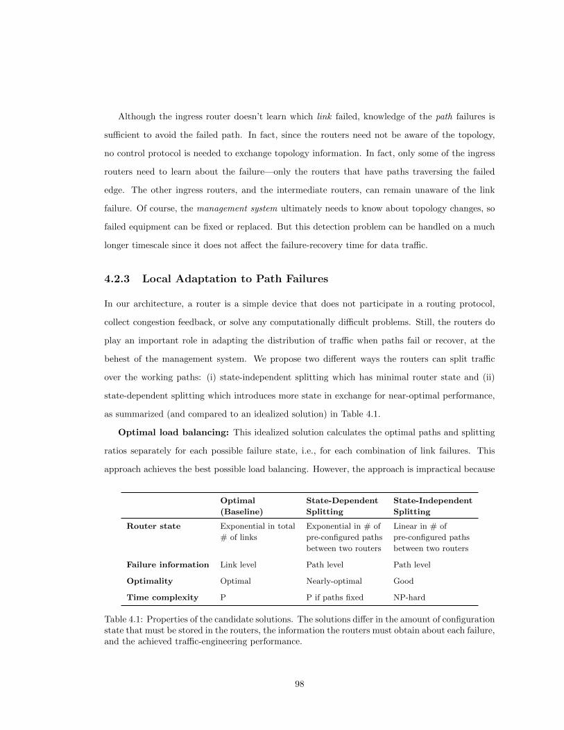
Although the ingress router doesn’t learn which link failed, knowledge of the path failures is
sufficient to avoid the failed path. In fact, since the routers need not be aware of the topology,
no control protocol is needed to exchange topology information. In fact, only some of the ingress
routers need to learn about the failure—only the routers that have paths traversing the failed
edge. The other ingress routers, and the intermediate routers, can remain unaware of the link
failure. Of course, the management system ultimately needs to know about topology changes, so
failed equipment can be fixed or replaced. But this detection problem can be handled on a much
longer timescale since it does not affect the failure-recovery time for data traffic.
4.2.3 Local Adaptation to Path Failures
In our architecture, a router is a simple device that does not participate in a routing protocol,
collect congestion feedback, or solve any computationally difficult problems. Still, the routers do
play an important role in adapting the distribution of traffic when paths fail or recover, at the
behest of the management system. We propose two different ways the routers can split traffic
over the working paths: (i) state-independent splitting which has minimal router state and (ii)
state-dependent splitting which introduces more state in exchange for near-optimal performance,
as summarized (and compared to an idealized solution) in Table 4.1.
Optimal load balancing: This idealized solution calculates the optimal paths and splitting
ratios separately for each possible failure state, i.e., for each combination of link failures. This
approach achieves the best possible load balancing. However, the approach is impractical because
Optimal State-Dependent State-Independent
(Baseline) Splitting Splitting
Router state Exponential in total Exponential in # of Linear in # of
# of links pre-configured paths pre-configured paths
between two routers between two routers
Failure information Link level Path level Path level
Optimality Optimal Nearly-optimal Good
Time complexity P P if paths fixed NP-hard
Table 4.1: Properties of the candidate solutions. The solutions differ in the amount of configurationstate that must be stored in the routers, the information the routers must obtain about each failure,and the achieved traffic-engineering performance.
98

the routers must (i) store far too much state and (ii) learn about all link failures—even on links the
router’s paths do not traverse. Therefore, this solution would violate our architecture. However,
the solution is still interesting as it provides a lower bound on the amount of congestion achievable
by the other two schemes.
State dependent splitting: In this solution, each ingress router has a separate configuration
entry with path-splitting weights for each combination of path failures to a particular egress router.
For example, suppose a router has three paths to an egress router. Then, the router configuration
contains seven entries—one for each of the 23−1 combinations of path failures. Each configuration
entry, computed ahead of time by the management system, consists of three weights—one per
path, with a 0 for any failed paths. Upon detecting path failures, the ingress router inspects a
pre-configured table to select the appropriate weights for splitting the traffic destined to the egress
router. Our experiments in Section 4.4 show that, even in a large ISP backbone, having three
or four paths is sufficient, leading to modest state requirements on the router in exchange for
near-optimal load balancing.
State independent splitting: This solution further simplifies the router configuration by
having a single set of weights across all failure scenarios. So, an ingress router with three paths
to an egress router would have only three weights, one for each path. If any paths fail, the
ingress router simply renormalizes the traffic on the remaining paths. As such, the management
system must perform a robust optimization of the limited configuration parameters to achieve good
load-balancing performance across a range of failure scenarios. Our experiments in Section 4.4
show that this simple approach can perform surprisingly well, but understandably not as well as
state-dependent splitting.
4.3 Network-Wide Optimization
In our architecture, the network-management system performs network-wide optimization to com-
pute paths and traffic-splitting ratios that balance load effectively across a range of failure sce-
narios. In this section, we first discuss the information the management system has about the
network topology, traffic demands, and shared risks. Then, we explain how the management sys-
tem computes the multiple diverse paths and the traffic-splitting ratios, for both state-dependent
99

and state-independent splitting. We solve all optimization problems either by formulating them as
convex optimizations solvable in polynomial time, or by providing heuristics for solving NP-hard
problems. Table 4.2 summarizes the notation.
4.3.1 Network-Wide Visibility and Control
The management system computes paths and splitting ratios based on a network-wide view:
Fixed topology: The management system makes decisions based on the designed topology
of the network—the routers and links that have been deployed. The topology is represented by
a graph G(V,E) with a set of vertices V and directed edges E. The capacity of edge e ∈ E is
denoted by ce, and the propagation delay on the edge is ye.
Shared risk link groups: The management system knows which links share a common
vulnerability, such as connecting to the same line card or router or traversing the same optical
Variable Description
G(V,E) network with vertices V and directed edges E
ce capacity of edge e ∈ Eye propagation delay on edge e ∈ E
S family of network failure states
s network failure state (set of failed links)
ws weight of network failure state s ∈ S
D set of demands
ud source of demand d ∈ Dvd destination of demand d ∈ Dhd flow requirement of demand d ∈ D
Pd paths available to demand d ∈ Dαp fraction of the demand assigned to path p
Od family of observable failure states for node udod(s) state observable by ud in failure state s ∈ SP od paths available to ud in failure state o ∈ Odfsp flow on path p in failure state s ∈ Sfop flow on path p in failure state o ∈ Odlse total flow on edge e in failure state s
lse,d flow of demand d on edge e in failure state s
Table 4.2: Summary of notation
100

fiber or amplifier [51]. The shared risks are denoted by the set S, where each s ∈ S consists of a
set of edges that may fail together. For example, a router failure is represented by the set of its
incident links, a fiber cut is represented by all links in the affected fiber bundle, and the failure-free
case is represented by the empty set ∅. Operators also have measurement data from past failures
to produce estimates for the likelihood of different failures (e.g., an optical amplifier may fail less
often than a line card). As such, each failure state s has a weight ws that represents its likelihood
or importance.
Expected traffic demands: The management system knows the anticipated traffic demands,
based on past measurements and predictions of traffic changes. Each traffic demand d ∈ D is
represented by a triple (ud, vd, hd), where ud ∈ V is the traffic source (ingress router), vd ∈ V is
the destination (egress router), and hd is the flow requirement (measured traffic). For simplicity,
we assume that all demands remain connected for each failure scenario; alternatively, a demand
can be omitted for each failure case that disconnects it. In practice, the management system may
have a time sequence of traffic demands (e.g., for different hours in the day), and optimize the
network configuration across all these demands, as we discuss in Section 4.4.3.
The management system’s output is set of paths Pd for each demand d and the splitting ratios
for each path. In each failure state s, the traffic splitting by ingress router ud depends only on
which paths have failed, not which failure scenario s has occurred; in fact, multiple failure scenarios
may affect the same subset of paths in Pd. To reason about the handling of a particular demand d,
we consider a set Od of “observable” failure states, where each observable state o ∈ Od corresponds
to a particular P od ⊂ Pd representing the available paths. For ease of expression, we let the function
od(s) map to the failure state observable by node ud when the network is in failure state s ∈ S.
The amount of flow assigned to path p in observable failure state o ∈ Od is fop . The total flow on
edge e in failure state s is lse, and the flow on edge e corresponding to demand d is lse,d.
The management system’s goal is to compute paths and splitting ratios that minimize con-
gestion over the range of possible failure states. A common traffic-engineering objective [35] is
to minimize∑e∈E Φ(lse/ce) where le is the load on edge e and ce is its capacity. Φ() could be a
convex function of link load [35], to penalize the most congested links while still accounting for
101
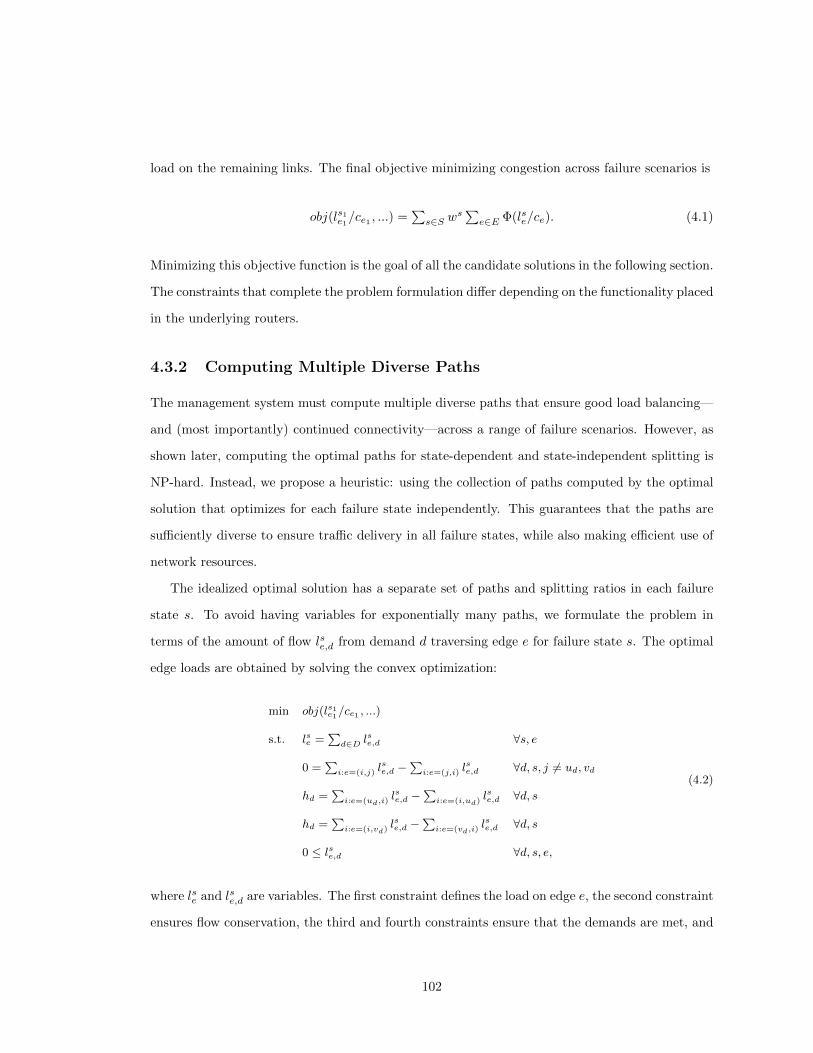
load on the remaining links. The final objective minimizing congestion across failure scenarios is
obj(ls1e1/ce1 , ...) =∑s∈S w
s∑e∈E Φ(lse/ce). (4.1)
Minimizing this objective function is the goal of all the candidate solutions in the following section.
The constraints that complete the problem formulation differ depending on the functionality placed
in the underlying routers.
4.3.2 Computing Multiple Diverse Paths
The management system must compute multiple diverse paths that ensure good load balancing—
and (most importantly) continued connectivity—across a range of failure scenarios. However, as
shown later, computing the optimal paths for state-dependent and state-independent splitting is
NP-hard. Instead, we propose a heuristic: using the collection of paths computed by the optimal
solution that optimizes for each failure state independently. This guarantees that the paths are
sufficiently diverse to ensure traffic delivery in all failure states, while also making efficient use of
network resources.
The idealized optimal solution has a separate set of paths and splitting ratios in each failure
state s. To avoid having variables for exponentially many paths, we formulate the problem in
terms of the amount of flow lse,d from demand d traversing edge e for failure state s. The optimal
edge loads are obtained by solving the convex optimization:
min obj(ls1e1/ce1 , ...)
s.t. lse =∑d∈D lse,d ∀s, e
0 =∑i:e=(i,j) l
se,d −
∑i:e=(j,i) l
se,d ∀d, s, j 6= ud, vd
hd =∑i:e=(ud,i)
lse,d −∑i:e=(i,ud)
lse,d ∀d, s
hd =∑i:e=(i,vd)
lse,d −∑i:e=(vd,i)
lse,d ∀d, s
0 ≤ lse,d ∀d, s, e,
(4.2)
where lse and lse,d are variables. The first constraint defines the load on edge e, the second constraint
ensures flow conservation, the third and fourth constraints ensure that the demands are met, and
102

the last constraint guarantees flow non-negativity. An optimal solution can be found in polynomial
time using conventional techniques for solving multi-commodity flow problems.
After obtaining the optimal flow on each edge for all the failure scenarios, we use a standard
decomposition algorithm to determine the corresponding paths Pd and the flow fsp on each of
them. The decomposition starts with a set Pd that is empty. New unique paths are added to the
set by performing the following decomposition for each failure state s. First, annotate each edge e
with the value lse,d. Remove all edges that have 0 value. Then, find a path connecting ud and vd.
Although we could choose any of the paths from ud to vd, our goal is to obtain paths that are as
short as possible. So, if multiple such paths exist, we use the path p with the smallest propagation
delay. Add this path p to the set Pd and assign to it flow fsp equal to the smallest value of the
edges on path p. Reduce the values of these edges accordingly. Continue in this fashion, removing
edges with zero value and finding new paths, until there are no remaining edges in the graph.
Note that we can show by induction that this process completely partitions the flow lse,d into
paths. The decomposition yields at most |E| paths for each network failure state s because the
value of at least one edge becomes 0 whenever a new path is found. Hence the total size of the set
Pd is at most |E||S|. It is difficult to obtain a solution that restricts the number of paths as we
prove in Section 4.7 that it is NP-hard to solve problem (4.2) when the number of allowed paths is
bounded by a constant J . In practice, the algorithm produces a relatively small number of paths
between each pair of edge routers, as shown later in Section 4.4.
4.3.3 Optimizing the Traffic-Splitting Ratios
Once the paths are computed, the network-management system can optimize the path-splitting
ratios for each ingress-egress router pair. The optimization problem and the resulting solution
depend on whether the routers perform state-dependent or state-independent splitting.
State-Dependent Splitting
In state-dependent splitting, each ingress router ud has a set of splitting ratios for each observable
failure state o ∈ Od. Since the path-splitting ratios depend on which paths in Pd have failed, the
ingress router must store splitting ratios for min(|S|, 2|Pd|) scenarios; fortunately, the number of
paths |Pd| is typically small in practice. When the network performs such state-dependent splitting,
103

the management system’s goal is to find a set of paths Pd for each demand and the flows fop on
these paths in all observable states o ∈ Od. If the paths Pd are known and fixed, the problem can
be formulated as a convex optimization:
min obj(ls1e1/ce1 , ...)
s.t. lse =∑d∈D
∑p∈Po
d,e∈p
fop ∀e, s, o = od(s)
hd =∑p∈Po
dfop ∀d, o ∈ Od
0 ≤ fop ∀d, o ∈ Od, p ∈ Pd,
(4.3)
where lse and fop are variables. The first constraint defines the load on edge e, the second constraint
guarantees that the demand d is satisfied in all observable failure states, and the last constraint en-
sures non-negativity of flows assigned to the paths. The solution of the optimization problem (4.3)
can be found in polynomial time.
Finding the optimal set of paths {Pd} in problem (4.3) is NP-hard. Section 4.7 shows that it is
NP-hard to construct a path (if one exists) that allows the ingress router to distinguish the failure
state s. This is required to decide how to best balance the load. All our formulations where the
routers cannot directly observe link failures are NP-hard. Therefore, we use the paths that are
found by the decomposition of the optimal solutions (4.2), as outlined in the previous subsection.
Since these paths allow optimal load balancing for the optimal solutions (4.2), they are also likely
to enable good load balancing for the optimization problem (4.3).
State-Independent Splitting
In state independent splitting, each ingress router has a single configuration entry containing the
splitting ratios that are used under any combination of path failures. Each path p is associated
with a splitting fraction αp. When one or more paths fail, the ingress router ud observes state o
and usesαp∑
q∈Podαq
as the splitting ratio for path p (and 0 for all the failed paths). If the network
elements implement such state-independent splitting, and the paths Pd are known and fixed, the
management system needs to solve the following non-convex optimization problem:
104

min obj(ls1e1/ce1 , ...)
s.t. fop = hdαp∑
q∈Podαq
∀d, o ∈ Od, p ∈ Pd
lse =∑d∈D
∑p∈Po
d,e∈p
fop ∀e, s, o = od(s)
0 ≤ fop ∀d, o ∈ Od, p ∈ Pd,
(4.4)
where lse, fop and αp are variables. The first constraint ensures that the flow assigned to every
available path p is proportional to αp. The other three constraints are the same as in (4.3).
Unfortunately, no standard optimization techniques allow us to compute an optimal solution
efficiently, even when the paths Pd are fixed. Therefore, we have to rely on heuristics to find both
the candidate paths Pd and the splitting ratios αp. To find the set of candidate paths Pd, we again
use the optimal paths obtained by decomposing (4.2). To find the splitting ratios we mimic the
behavior of the optimal solution as closely as possible. We find the splitting ratios for all paths
p by letting αp =∑s∈S
wsfsp
hdwhere fsp is the flow assigned by the optimal solution to path p
in network failure state s. Since∑ws = 1, the calculated ratio is the weighted average of the
splitting ratios used by the optimal solutions (4.2).
4.4 Experimental Evaluation
To evaluate the algorithms described in the previous section, we wrote a simulator in C++ that
calls the CPLEX linear program solver in AMPL and solves the optimization problems (4.2)
and (4.3). We compare our two heuristics to the optimal solution, a simple “equal splitting”
configuration, and OSPF with the link weights set using state-of-the-art optimization techniques.
We show that our two heuristics require few paths resulting in compact routing tables, and the
round-trip propagation delay does not increase. Finally, using real traffic traces obtained during a
24-hour measurement in the network of a tier-1 ISP we show that our solutions achieve excellent
results without the need to perform any reoptimizations even in the presence of a changing traffic
matrix.
Our experimental results show that the objective value of state-dependent splitting
very closely tracks the optimal objective. For this reason, this solution is our favorite.
105

Although state-independent splitting has somewhat worse performance especially as the network
load increases beyond current levels, it is also attractive due to its simplicity.
4.4.1 Experimental Setup
Our simulations use a variety of synthetic topologies, the Abilene topology, as well as the city-level
IP backbone topology of a tier-1 ISP with a set of failures provided by the network operator. The
parameters of the topologies we used are summarized in Table 4.3.
Synthetic topologies: The synthetic topologies include 2-level hierarchical graphs, purely ran-
dom graphs, and Waxman graphs. 2-level hierarchical graphs are produced using the generator
GT-ITM [102], for random graphs the probability of two edges being connected is constant, and
the probability of having an edge between two nodes in the Waxman graph decays exponentially
with the distance of the nodes. These topologies also appear in [34].
Abilene topology: The topology of the Abilene network and a measured traffic matrix are used.
We use the true edge capacities of 10 Gbps.
Tier-1 IP backbone: The city-level IP backbone of a tier-1 ISP is used. In our simulations, we
use the real link capacities, link round-trip propagation delays, and measured traffic demands.
The collection of network failures S for the synthetic topologies and Abilene contains single
edge failures and the no-failure case. Two experiments with different collections of failures are
performed on the tier-1 IP backbone. In the first experiment, single edge failures are used. In the
second experiment, the collection of failures also contains Shared Risk Link Groups (SRLGs), link
Name Topology Nodes Edges Demands
hier50a hierarchical 50 148 2,450
hier50b hierarchical 50 212 2,450
rand50 random 50 228 2,450
rand50a random 50 245 2,450
rand100 random 100 403 9,900
wax50 Waxman 50 169 2,450
wax50a Waxman 50 230 2,450
Abilene backbone 11 28 110
tier-1 backbone 50 180 625
Table 4.3: Synthetic and realistic network topologies.
106

failures that occur simultaneously. SRLGs were obtained from the network operator’s database
that contains 954 failures with the largest failure affecting 20 links simultaneously. For each
potential line card failure, a complete router failure, or a link cut there is a corresponding record
in the SRLG database. Therefore, failures that do not appear in the database are rare. The
weights ws in the optimization objective (4.1) were set to 0.5 for the no-failure case, and all other
failure weights are equal and sum to 0.5.
The set of demands D in the Abilene and tier-1 networks were obtained by sampling Netflow
data measured on Nov. 15th 2005 and May 22nd 2009, respectively. For the synthetic topologies,
we chose the same traffic demands as in [34].
To simulate the algorithms in environments with increasing congestion, we repeat all experi-
ments several times while uniformly increasing the traffic demands. For the synthetic topologies
we start with the original demands and scale them up to twice the original values. As the average
link utilization in Abilene and the tier-1 topology is lower than in the synthetic topologies, we
scale the demands in these realistic topologies up to three times the original value.
In our experiments we use the piecewise linear penalty function defined by Φ(0) = 0 and its
derivatives:
Φ′ (`) =
1 for 0 ≤ ` < 0.333
3 for 0.333 ≤ ` < 0.667
10 for 0.667 ≤ ` < 0.9
70 for 0.9 ≤ ` < 1
500 for 1 ≤ ` < 1.1
5000 for 1.1 ≤ ` <∞This penalty function was introduced in [35], and allows one to formulate the optimizations (4.2)
and (4.3) as linear programs by adding auxiliary variables. The function can be viewed as modeling
retransmission delays caused by packet losses. The cost is small for low utilization, and increases
steeply as the utilization exceeds 100%.
Our simulation calculates the objective value of the optimal solution, state-independent and
state-dependent splitting, and equal splitting. Equal splitting is a variant of state-independent
splitting that splits the flow evenly on the available paths. We also calculate the objective achieved
by the shortest path routing of OSPF with optimized link weights. These link weights were cal-
107

culated using the state-of-the-art optimizations of [34], and these optimizations take into consid-
eration the set of failure states S and the corresponding failure weights ws.
Our simulations were performed using CPLEX version 11.2 on a 1.5 GHz Intel Itanium 2
processor. Solving the linear program for (4.2) for a particular failure case in the tier-1 topology
takes 4 seconds, and solving the linear program (4.3) takes about 16 minutes. A tier-1 network
operator can perform calculations for its entire city-level topology in less than 2 hours.
4.4.2 Performance with Static Traffic
Avoiding congestion and packet losses during planned and unplanned failures is the central goal of
traffic engineering. Our traffic engineering objective measures congestion across all the considered
failure cases. The objective as a function of the scaled-up demands is depicted in Figure 4.2 and 4.3.
The results which were obtained on the hierarchical and tier-1 topologies are representative, we
made similar observations for all the other topologies. In Figure 4.2 and 4.3, the performance
of state-dependent splitting and the optimal solution is virtually indistinguishable in all cases.
State-independent splitting is less sophisticated and does not allow custom load balancing ratios
for distinct failures, and therefore its performance is worse compared to the optimum. It is not
surprising that the equal splitting algorithm achieves the worst performance.
0
200000
400000
600000
800000
1e+06
1.2e+06
1 1.2 1.4 1.6 1.8 2
obje
ctiv
e va
lue
network traffic
OSPFequal splitting
state indep. splittingstate dep. splitting
global optimum
Figure 4.2: The traffic engineering objective as a function of an increasing traffic load in the hier-archical topology hier50a. The performance of the optimal solution and state-dependent splittingis nearly identical.
108

2e+06
3e+06
4e+06
5e+06
6e+06
7e+06
8e+06
1 1.5 2 2.5 3
obje
ctiv
e va
lue
network traffic
OSPFequal splitting
state indep. splittingstate dep. splitting
global optimum
2e+06
4e+06
6e+06
8e+06
1e+07
1.2e+07
1 1.5 2 2.5 3
obje
ctiv
e va
lue
network traffic
OSPFequal splitting
state indep. splittingstate dep. splitting
global optimum
Figure 4.3: From top to bottom the traffic engineering objective as a function of an increasingtraffic load in the tier-1 topology with single edge failures, and the tier-1 topology with SRLGs,respectively. The performance of the optimal solution and state-dependent splitting is nearlyidentical.
We observe that OSPF achieves a somewhat worse performance than state-independent and
state-dependent splitting as the load increases. However, we should note that in OSPF, each
router is restricted to sending all its traffic on the single path with the smallest weight, or splitting
the traffic evenly if multiple smallest-weight paths exist. This approach does not allow the same
flexibility in choosing routes and splitting ratios as our solution, and, therefore, OSPF should not
be expected to achieve the same performance even for an optimal choice of OSPF link weights.
109

0
0.2
0.4
0.6
0.8
1
2 3 4 5 6 7 8 9 10
cdf
number of paths
abilenewax50
tier-1hier50a
tier-1 (SRLGs)
0
0.2
0.4
0.6
0.8
1
2 3 4 5 6 7 8 9 10
cdf
number of paths
traffic=1.0traffic=1.8traffic=2.6
Figure 4.4: The number of paths used in various topologies at the top, and in the tier-1 topologywith SRLGs at the bottom. The cumulative distribution function shows that the number of pathsis almost independent of the traffic load in the network, but is larger for bigger, more well-connectedtopologies.
Solutions with few paths are preferred as they decrease the number of tunnels that have to be
managed, and reduce the size of the router configuration. However, a sufficient number of paths
must be available to avoid failures and to reduce congestion. We observe that the number of paths
used by our algorithms is small. We record the number of paths used by each demand, and plot
the distribution in Figure 4.4. Not surprisingly, the number of paths is greater for larger and more
diverse topologies. 92% of the demands in the hierarchical topology use 7 or fewer paths, and
110

fewer than 10 paths are needed in the tier-1 backbone topology for almost all demands. Further,
Figure 4.4 shows that the number of paths only increases slightly as we scale up the amount of
traffic in the networks. This small increase is caused by shifting some traffic to longer paths as
the short paths become congested.
A practical solution uses few MPLS labels in order to reduce the size of routing tables in the
routers. Our experimental results reveal that when we use MPLS tunnels in the tier-1 topology, a
few thousand tunnels can pass through a single router. However, a simple routing table compres-
sion technique allows us to reduce the routing table size to a few hundred entries in each router.
Such compression is important because it reduces the memory requirements imposed on the simple
routers whose use we advocate, and it improves the route lookup time.
Routing tables can be compressed by using the same MPLS labels for routes with a common
path to the destination. Specifically, if two routes to destination t pass through router r, and these
routes share the same path between the router r and the destination t, the same outbound label
should be used in the routing table of router r. The resulting routing table sizes as a function of
the network load are depicted in Figure 4.5. The curve on the top shows the size of the largest
routing table, and the curve on the bottom shows the average routing table size among all the
backbone routers.
0
50
100
150
200
250
300
350
1 1.5 2 2.5 3
rout
ing
tabl
e si
ze
network traffic
max sizeavg size
Figure 4.5: Size of the compressed routing tables in the tier-1 topology with SRLGs. The largestand average routing table sizes (± one standard deviation) in the backbone routers are shown.
111

Minimizing the delay experienced by the users is another important goal of network operators.
We calculated the average round-trip propagation delays of all the evaluated algorithms. The
calculated delays include delays in all failure states weighted by the corresponding likelihood
of occurrence, but exclude congestion delay which is negligible. The delays are summarized in
Table 4.4. We observe that the round-trip delay of all algorithms except equal splitting is almost
identical at around 31 ms. These values would satisfy the 37 ms requirement specified in the SLAs
of the tier-1 network. Moreover, these values are not higher than these experienced by the network
users today. To demonstrate this, we repeated our simulation on the tier-1 topology using the
real OSPF weights which are used by the network operator. These values are chosen to provide
a tradeoff between traffic engineering and shortest delay routing. The results which appear in
Table 4.4 in the row titled OSPF (current) show that the current delays are 31.38 ms for each of
the two tier-1 failure sets.
Algorithm Single edge SRLGs
Optimal load balancing 31.75± 0.26 31.80± 0.25
State dep. splitting 31.51± 0.17 31.61± 0.16
State indep. splitting 31.76± 0.26 31.87± 0.25
Equal splitting 34.83± 0.33 40.85± 0.86
OSPF (optimized) 31.18± 0.40 31.23± 0.40
OSPF (current) 31.38± 0 31.38± 0
Table 4.4: Round-trip propagation delay in ms (average ± one standard deviation) in the tier-1backbone network for single edge failures and SRLG failures.
4.4.3 Robust Optimization for Dynamic Traffic
Solving the optimization problems repeatedly as the traffic matrix changes is undesirable due to
the need to update the router configurations with new paths and splitting ratios. We explore the
possibility of using a single router configuration that is robust to diurnal changes of the demands.
To perform this study we collected hourly Netflow traffic traces in the tier-1 network on Septem-
ber 29, 2009. We denote the resulting 24 hourly traffic matrices D0, D1, ..., D23. Figure 4.6 depicts
the aggregate traffic volume, as well as example of the traffic between three ingress-egress router
pairs. The aggregate traffic volume is the lowest at 9 a.m. GMT and peaks with 2.5 times as much
traffic at midnight and 8 p.m. GMT. Comparison to the three depicted ingress-egress router de-
112

0
20
40
60
80
100
5 10 15 20
rela
tive
traf
fic v
olum
e (%
)
time (GMT)
aggregate volumeflow 1flow 2flow 3
Figure 4.6: The aggregate traffic volume in the tier-1 network has peaks at midnight GMT and 8p.m. GMT. Examples of three demands show that their peaks occur at different times of the day.
mands reveals that the traffic during a day cannot be obtained by simple scaling as the individual
demands peak at different times. This makes the joint optimization challenging.
The first step in the joint optimization is to calculate a single set of paths that guarantee failure
resilience and load balancing for each of the 24 traffic matrices. There are several approaches we
can take. In the first approach, we solve the linear program for (2) for each traffic matrix Di
separately and use the union of the paths obtained for each matrix. The second approach is to
calculate the average traffic matrix D = 124
∑iD
i. The linear program for (2) is then solved for
the average traffic matrix. In the third approach we use the envelope of the 24 traffic matrices
instead of the average, i.e., we let Djk = maxiDijk.
In our simulations we chose the last method. Compared to the first method, it results in fewer
paths. Compared to the second method, it allows better load balancing because demands between
ingress-egress pairs with high traffic variability throughout the day are represented by the peak
traffic.
The second step is to calculate router configuration robust to traffic changes. We again use
the envelope Djk = maxiDijk as the input traffic matrix and repeat the optimizations from the
previous section. Then we test the solution by simulating the varying traffic demand during one
day period. The resulting objective value of state dependent splitting and state independent
113

1e+06
1.5e+06
2e+06
2.5e+06
3e+06
3.5e+06
4e+06
4.5e+06
5 10 15 20
obje
ctiv
e va
lue
time (GMT)
state dep. splittingglobal optimum
state indep. splitting
Figure 4.7: The traffic engineering objective in the tier-1 topology with SRLGs. The state de-pendent and state independent splitting algorithms use a single configuration throughout the day.The optimal solution uses a custom configuration for each hour.
splitting is depicted in Figure 4.7. The optimal objective in Figure 4.7 represents the performance
of the best possible solution that uses custom configuration updated hourly. We observe that state
dependent splitting with a single configuration is robust to diurnal traffic changes and the value
of its objective closely tracks the optimum. State independent splitting is also close to optimal
during low congestion periods, but becomes suboptimal during the peak hours.
4.5 Deployment Scenarios
Although our architecture enables the use of new simpler routers, we can readily deploy our
solutions using existing protocols and equipment, as summarized in Table 4.5. An ISP can deploy
our architecture using Multi-Protocol Label Switching (MPLS) [82]. Data centers could use the
same solution, or leverage existing Ethernet switches and move some functionality into the end-
host machines.
4.5.1 ISP Backbone Using MPLS
Installing MPLS paths with RSVP: MPLS is particularly suitable because ingress routers en-
capsulate packets with labels and direct them over pre-established Label-Switched Paths (LSPs).
114

ISP Backbone Data Center
Network element MPLS router Ethernet switch
Path installation RSVP VLAN trunking
Traffic splitting Ingress router End host
Failure detection BFD Host probing
Fast recovery Ingress router End host
Traffic demand MPLS MIB Host/VLAN counter
Table 4.5: Existing tools and protocols that can be used to deploy our architecture.
This enables flexible routing when multiple LSPs are established between each ingress-egress router
pair. Our solution, then, could be viewed as a particular application of MPLS, where the manage-
ment system computes the LSPs, instructs the ingress routers to establish the paths (say, using
RSVP), and disables any dynamic recalculation of alternate paths when primary paths fail.
Hash-based splitting at ingress routers: Multipath forwarding is supported by commercial
routers of both major vendors [3,76]. The routers can be configured to hash packets based on port
and address information in the headers into several groups and forward each group on a separate
path. This provides path splitting with relatively fine granularity (e.g., at the 1/16th level), while
preventing out-of-order packet delivery by ensuring that packets belonging to the same TCP or
UDP flow traverse the same path.
Path-level failure detection using BFD: Fast failure detection can be done using Bidi-
rectional Forwarding Detection (BFD) [56]. A BFD session can monitor each path between two
routers, by piggybacking on the existing data traffic. (Backbones covering a large geographic region
may also use existing link-level detection mechanisms for even faster recovery. For example, local
path protection [77] installs a short alternate path between two adjacent routers, for temporary
use after the direct link fails. However, local protection cannot fully exploit the available path di-
versity, leading to suboptimal load balancing; instead, local protection can be used in conjunction
with our design.)
Failure recovery at ingress router: The ingress router adapts to path failures by splitting
traffic over the remaining paths. In state-independent splitting, the ingress router has a single
set of traffic-splitting weights, and automatically renormalizes to direct traffic over the working
paths. State-dependent splitting requires modification to the router software to switch to alternate
traffic-splitting weights in the data plane; no hardware modifications are required.
115

Measuring traffic demands using SNMP: MPLS has SNMP counters (called Management
Information Bases) that measure the total traffic traversing each Label-Switched Path. The man-
agement system can poll these counters to measure the traffic demands. Alternative measurement
techniques, such as Netflow or tomography, may also be used.
4.5.2 Data Center Using Hosts and Switches
While a data center could easily use the same MPLS-based solution, control over the end host and
the availability of cheaper commodity switches enable another solution.
End-host support for monitoring and traffic splitting: The server machines in data
centers can perform many of the path-level operations in our architecture. As in the VL2 [40] and
SPAIN [70] architectures, the end host can encapsulate the packets (say, using a VLAN tag) to
direct them over a specific path. This enables much finer-grain traffic splitting. In addition, the
end host can perform path-level probing in the data plane, by piggybacking on existing data traffic
and sending additional active probes when needed. Upon detecting path failures, the end host can
change to new path-splitting percentages based on the precomputed configuration installed by the
controller. The end host could also measure the traffic demands by keeping counts of the traffic
destined to each egress switch. These functions can be implemented in the hypervisor, such as the
virtual switch that often runs on server machines in data centers.
Multiple VLANs or OpenFlow rules for forwarding: The remaining functions can
be performed by the underlying switches. For example, the management system can configure
multiple paths by merging these paths into a set of trees, where each tree corresponds to a different
VLAN [70]. Or, if the switches support the emerging OpenFlow standard [1,67], the management
system could install a forwarding-table rule for each hop in each path, where the rule matches on
the VLAN tag, and forwards the packet to the appropriate output port. Since OpenFlow switches
maintain traffic counters for each rule, the management system can measure the traffic demands
by polling the switches, in lieu of the end hosts collecting these measurements.
116

4.6 Related Work
Traffic engineering: Most of the related work treats failure recovery and traffic engineering
independently. Traffic engineering without failure recovery in the context of MPLS is studied
in [26, 29, 63, 87, 98]. The work in [26] utilizes traffic splitting to minimize end-to-end delay and
loss rates; however, an algorithm for optimal path selection is not provided. The works in [63]
and [87] minimize the maximum link utilization while satisfying the requested traffic demands.
Other papers [29, 52, 60, 98] prevent congestion by adaptively balancing the load among multiple
paths based on measurements of congestion, whereas our solution precomputes traffic-splitting
configurations based on both the offered traffic and the likely failures.
Failure recovery: Local and global path protection are popular failure recovery mechanisms
in MPLS. In local protection the backup path takes the shortest path that avoids the outage
location from a point of local repair to the merge point with the primary path. The IETF RFC
4090 [77] focuses on defining signaling extensions to establish the backup paths, but leaves the
issues of bandwidth reservation and optimal route selection open. In [95] the shortest path that
avoids the failure is used. While [85] and [97] attempt to find optimal backup paths with the
goal of reducing congestion, local path protection is less suitable for traffic engineering than global
path protection, which allows rerouting on end-to-end paths [89]. Other work describes how to
manage restoration bandwidth and select optimal paths [59, 64]. While our solution also uses
global protection to reroute around failures, the biggest difference is that most of the related work
distinguishes primary and backup paths and only uses a backup path when the primary path fails.
In contrast, our solution balances the load across multiple paths even before failures occur, and
simply adjusts the splitting ratios in response to failures.
Integrated failure recovery and TE: Some proposals only use alternate paths when primary
routes fail [84], or they require explicit congestion feedback and do not provide algorithms to find
the optimal paths [62,68]. YAMR [36] constructs a set of diverse paths in the interdomain routing
setting that are resilient against a specified set of failures, but without regard to load balancing.
In [103] they integrate failure recovery with load balancing, but their focus is different—they
guarantee delivery of a certain fraction of the traffic after a single edge failure, whereas our goal
is to deliver all traffic for a known set of multi-edge failures. In [99] they propose an architecture
117

that handles up to F link failures by using local rerouting, subject to link capacity constraints.
Unlike [99], our work uses end-to-end routing, and does not require link state flooding and dynamic
router reconfigurations. Proposals that optimize OSPF or IS-IS link weights with failures in mind,
such as [34] and [72], must rely on shortest path IGP routing and therefore cannot fully utilize the
path diversity in the network.
Failure recovery and TE with multiple spanning trees: Enterprise and data-center
networks often use Ethernet switches, which do not scale well because all traffic flows over a single
spanning tree, even if multiple paths exist. Several papers propose more scalable Ethernet designs
that use multiple paths. The work of Sharma et al. uses VLANs to exploit multiple spanning
trees to improve link utilization, and achieve improved fault recovery [88]. Most of the designs
such as VL2 [40], and PortLand [71] rely on equal splitting of traffic on paths with the same cost.
SPAIN [70] supports multipath routing through multiple spanning trees, with end hosts splitting
traffic over the multiple paths. However, the algorithm for computing the paths does not consider
the traffic demands, and the end hosts must play a stronger role in deciding which path to use for
each individual flow based on the observed performance.
NP-hardness: Hardness proofs of optimization problems related to failure recovery appear,
e.g., in [94] and [25].
4.7 Proofs
This section shows that two problems are NP-hard:
Failure State Distinguishing
instance: A directed graph G = (V,E), source and destination vertices u, v ∈ V , and a sets
s ⊆ E.
question: Is there a simple directed path P from u to v that is up if the edges in s do not fail
and down if they fail?
Bounded Path Load Balancing
instance: A directed graph G = (V,E) with a positive rational capacity ce for each edge e ∈ E,
a collection S of subsets s ⊆ E of failure states with a rational weight ws for each s ∈ S, a set of
triples (ud, vd, hd), 1 ≤ d ≤ k, corresponding to demands, where hd units of demand d need to be
118

sent from source vertex ud ∈ V to destination vertex vd ∈ V , an integer bound J on the number
of paths that can be used between any source-destination pair, a piecewise-linear increasing cost
function Φ(`) mapping edge loads ` to rationals, and an overall cost bound B.
question: Are there J (or fewer) paths between each source-destination pair such that the given
demands can be assigned to the paths so that the cost (sum of Φ(`) over all edges and weighted
failure states as described in the text) is B or less?
To prove that a problem X is NP-hard, we must show that for some known NP-hard problem
Y , any instance y of Y can be transformed into an instance x of X in polynomial time, with the
property that the answer for y is yes if and only if the answer for x is yes. Both our problems can
be proved NP-hard by transformations from the following problem, proved NP-hard by Fortune,
Hopcroft, and Wyllie [33].
Disjoint Directed Paths
instance: A directed graph G(V,E) and distinguished vertices u1, v1, u2, v2 ∈ V .
question: Are there directed paths P1 from u1 to v1 and P2 from u2 to v2 such that P1 and P2
are vertex-disjoint?
Theorem 1. The Failure State Distinguishing problem is NP-hard.
Proof. Suppose we are given an instance G = (V,E), u1, v1, u2, v2 of Disjoint Directed
Paths. Our constructed instance of Failure State Distinguishing consists of the graph G′ =
(V,E′), where E′ = E ∪ {(v1, u2)}, with u = u1, v = v2, and s = {(v1, u2)}.
Given this choice of s, a simple directed path from u to v that is up only if the edge (v1, u2) is
up must contain that edge. We claim that such a path exists if and only if there are vertex-disjoint
directed paths P1 from u1 to v1 and P2 from u2 to v2. Suppose a distinguishing path P exists.
Then it must consist of of three segments: a path P1 from u = u1 to v1, the edge (v1, u2), and
then a path P2 from u2 to v = v2. Since it is a simple path, P1 and P2 must be vertex-disjoint.
Conversely, if vertex-disjoint paths P1 from u1 to v1 and P2 from u2 to v2 exist, then the path P
that concatenates P1 followed by (v1, u2) followed by P2 is our desired distinguishing path. �
Theorem 2. The Bounded Path Load Balancing problem is NP-hard even if there are only
two commodities (k = 2), only one path is allowed for each (J = 1), and there is only one failure
state s.
119

Proof. For this result we use the variant of Disjoint Directed Paths in which we ask for
edge-disjoint rather than vertex-disjoint paths. The NP-hardness of this variant is easy to prove,
using a construction in which each vertex x of G is replaced by a pair of new vertices inx and outx
connected by the edge (inx, outx), and each edge (x, y) of G is replaced by the edge (outx, iny).
Suppose we are given an instance G = (V,E), u1, v1, u2, v2 of the edge-disjoint variant of
Disjoint Directed Paths. Our constructed instance of Bounded Path Load Balancing is
based on the same graph, with each edge e given capacity ce = 1, with the single failure state
s = φ (i.e., the state with no failures), with ws = 1, and with demands represented by (u1, v1, 1)
and (u2, v2, 1). The cost function Φ has derivative Φ′(`) = 1, 0 ≤ ` ≤ 1, and Φ′(`) = |E| + 1,
` > 1. Our target overall cost bound is B = |E|.
If the desired disjoint paths exist, we can use P1 to send the required unit of traffic from u1 to
v1, and P2 to send the traffic from u2 to v2. Since the paths are edge-disjoint, no edge will carry
more than one unit of traffic, so the cost per edge used is 1, and the total number of edges used is
at most |E|. Thus the specified cost bound B = |E| is met. On the other hand, if no such pair of
paths exist, then we must choose paths P1 and P2 that share at least one edge, which will carry
two units of flow, for a cost of at least |E|+ 1, just for that edge. Thus if there is a solution with
cost |E| or less, the desired disjoint paths must exist. �
Adding more paths, failure states, or commodities cannot make the problem easier. Note,
however, that this does not imply that the problem for the precise cost function Φ presented in
the text is NP-hard. It does, however, mean that, assuming P 6= NP, any efficient algorithm for
that Φ would have to exploit the particular features of that function.
4.8 Summary
In this chapter we propose a mechanism that combines path protection and traffic engineering
to enable reliable data delivery in the presence of link failures. We formalize the problem by
providing several optimization-theoretic formulations that differ in the capabilities they require of
the network routers. For each of the formulations, we present algorithms and heuristics that allow
the network operator to find a set of optimal end-to-end paths and load balancing rules.
Our extensive simulations on the IP backbone of a tier-1 ISP and on a range of synthetic
120

topologies demonstrate the attractive properties of our solutions. First, state-dependent splitting
achieves load balancing performance close to the theoretical optimum, while state-independent
splitting often offers comparable performance and a very simple setup. Second, using our solutions
does not significantly increase propagation delay compared to the shortest path routing of OSPF.
Finally, our solution is robust to diurnal traffic changes and a single configuration suffices to
provide good performance.
In addition to failure resilience and favorable traffic engineering properties, our architecture
has the potential to simplify router design and reduce operation costs for ISPs as well as operators
of data centers and enterprise networks.
121

Chapter 5
Conclusion
This dissertation suggests three methods to improve reliability of the Internet by
analyzing three major weaknesses of state-of-the-art network routing protocols.
First, we introduced a new model, the Dynamic Path Vector Protocol (DPVP), that provides
a convenient and accurate framework for understanding the dynamic properties of interdomain
routing. Using this model, we resolved a decade-long open question that asks for the necessary and
sufficient conditions under which routing policies are safe. This in turn allowed us to design the
DeCoy algorithm that verifies safety of routing policies used in practice in polynomial time. Policy
induced oscillations are responsible for temporary losses of connectivity, creation of transient loops
leading to packet losses, and frequent route changes have negative impact on TCP performance.
Therefore, deployment of the DeCoy algorithm in the Internet has the potential to significantly
improve user perceived performance.
Second, we studied the security of interdomain routing. We started with the observation that
current proposals of secure interdomain routing protocols cannot yield measurable security benefits
in small scale deployments, and network operators do noth have incentives for early adoption. We
identified a combination of mechanisms that provides significant and measurable security benefits
to participants and non-participants alike even if the proposed solution is only deployed by a
small group of participants. If deployed in the Internet, our solution can significantly reduce
the occurrence of route blackholing and data interception caused either by malicious attacks or
accidental misconfigurations.
122

Third, we introduced a new simple network architecture that allows load balancing in the
presence of equipment failures in the networks of ISPs. Our solution is attractive because a simple
static preconfiguration of the network routers is sufficient to provide them with enough information
to perform well under a wide set of failures. Static configuration is also sufficient even for varying
traffic loads. The ability of our solution to select optimal routes without the need to perform
time-consuming reoptimizations can be translated to lower network management complexity, and
improved performance during the transient periods after each failure.
Several questions remain open:
• Our analysis of BGP safety is restricted to cases where the route preference function follows
the rule of independent ranking. However, as Griffin and Wilfong observed [41], iBGP
configurations that use the Multi Exit Discriminator (MED) violate the rule of independent
ranking, i.e., a route’s ranking can vary depending on the presence or absence of other routes.
How can we extend the DPVP model to analyze such cases?
• The DeCoy algorithm is a convenient tool that uses AS policies on the input and provides
policy conflicts on the output. However, routing policies are kept secret and ASes are not
willing to share them. What should a privacy preserving version of the DeCoy algorithm
look like? While it is certainly possible to apply standard techniques to make the algorithm
privacy preserving, what is the communication overhead, and would ASes be willing to use
the algorithm if some information about their policies can be inferred from the output of the
algorithm itself?
• Another open question concerns the action that ASes should take once, through the use of
the DeCoy algorithm, they detect policy conflicts. If a policy conflict can be resolved if one
of several ASes selects a higher cost route, how can the ASes agree who should adopt the
change?
In conclusion, we believe that deployment of the algorithms and techniques proposed in this
dissertation would result in a significant improvement of the reliability of the Internet. Moreover,
most of our techniques are general enough to be used as building blocks, and we hope that they
will be used to make future routing protocols more safe, secure, and reliable.
123

Bibliography
[1] OpenFlow Switch Consortium. http://www.openflowswitch.org/.
[2] 2010 Report to Congress of the U.S.-China Economic and Security Review Commission,
2010. http://www.uscc.gov/annual_report/2010/annual_report_full_10.pdf.
[3] JUNOS: MPLS fast reroute solutions, network operations guide. http://juniper.power.
net.id/techpubs/nog/nog-mpls-frr/download/nog-mpls-frr.pdf, 2011.
[4] Router reliability research (R3), 2011. http://r3.cis.upenn.edu/.
[5] ARIN IX Public Policy Meeting, http: // www. arin. net/ meetings/ minutes/ ARIN_ IX/
ppm_ minutes. html , Apr. 2002.
[6] http://www.ietf.org/html.charters/rpsec-charter.html.
[7] http://www.nanog.org/.
[8] S-BGP/soBGP Panel: What Do We Really Need and How Do We Architect a Compromise
to Get It?, http: // www. nanog. org/ mtg-0306/ sbgp. html , June 2003.
[9] D. Andersen, H. Balakrishnan, F. Kaashoek, and R. Morris. Resilent overlay networks. In
Proc. of SOSP, pages 131–145, 2001.
[10] I. Avramopoulos and J. Rexford. Stealth probing: Securing IP routing through data-plane
security. In Proc. of USENIX Annual Technical Conference, pages 267–272, 2006.
[11] I. Avramopoulos and J. Rexford. A pluralist approach to interdomain communication secu-
rity. In Proc. of NetEcon Workshop, 2007.
124

[12] T. Bates, R. Chandra, and E. Chen. BGP route reflection - an alternative to full mesh
iBGP, 2000. IETF RFC 2796.
[13] L. Benkis. Practical bgp security: Architecture, techniques and tools. http://www.renesys.
com/tech/notes/WP_BGP_rev6.pdf.
[14] R. Blog. Con-Ed steals the ’net. http://www.renesys.com/blog/2006/01/
conedstealsthenet.shtml.
[15] V. J. Bono. 7007 explanation and apology, Apr. 1997. http://www.merit.edu/mail.
archives/nanog/1997-04/msg00444.html.
[16] P. Boothe, J. Hiebert, and R. Bush. How prevalent is prefix hijacking on the Internet?, Feb.
2006. http://www.nanog.org/mtg-0602/boothe.html.
[17] R. Braden, L. Zhang, S. Berson, S. Herzog, and S. Jamin. Resource reservation protocol
(RSVP), 1997. IETF RFC 2205.
[18] M. Caesar, M. Casado, T. Koponen, J. Rexford, and S. Shenker. Dynamic route recompu-
tation considered harmful. SIGCOMM Comput. Commun. Rev., 40:66–71, 2010.
[19] M. Caesar and J. Rexford. BGP routing policies in ISP networks. IEEE Network Magazine,
19(6):5–11, 2005.
[20] http://as-rank.caida.org/data/.
[21] H. Chan, D. Dash, A. Perrig, and H. Zhang. Modeling adoptability of secure BGP protocols.
In Proc. of ACM SIGCOMM, pages 279–290, 2006.
[22] L. Cittadini, G. D. Battista, and M. Rimondini. How stable is stable interdomain routing:
Efficiently detectable oscillation-free configurations. Technical Report DIA-132-2008, Dept.
of CS&Automation, Roma Tre Univ., July 2008.
[23] L. Cittadini, G. D. Battista, M. Rimondini, and S. Vissicchio. Wheel + ring = reel: The
impact of route filtering on the stability of policy routing. In Proc. of ICNP, pages 274–283,
2009.
125

[24] R. Cornes and T. Sandler. The Theory of Externalities, Public Goods and Club Goods.
Cambridge University Press, second edition, 1996.
[25] D. Coudert, P. Datta, S. Perennes, H. Rivano, and M.-E. Voge. Shared risk resource group:
Complexity and approximability issues. Parallel Processing Letters, 17(2):169–184, 2007.
[26] E. Dinan, D. Awduche, and B. Jabbari. Analytical framework for dynamic traffic parti-
tioning in MPLS networks. In Proc. of IEEE International Conference on Communications,
volume 3, pages 1604–1608, 2000.
[27] M. Dobrescu, N. Egi, K. Argyraki, B.-G. Chun, K. Fall, G. Iannaccone, A. Knies, M. Manesh,
and S. Ratnasamy. RouteBricks: Exploiting parallelism to scale software routers. In Proc.
of SOSP, pages 15–28, 2009.
[28] N. Duffield and M. Grossglauser. Trajectory sampling for direct traffic observation.
IEEE/ACM Trans. Netw., 9(3):280–292, 2001.
[29] A. Elwalid, C. Jin, S. Low, and I. Widjaja. MATE: MPLS adaptive traffic engineering. In
Proc. of INFOCOM, volume 3, pages 1300–1309, 2001.
[30] A. Fabrikant and C. H. Papadimitriou. The complexity of game dynamics: BGP oscillations,
sink equilibria, and beyond. In Proc. of SODA, pages 844–853, 2008.
[31] A. Fabrikant, U. Syed, and J. Rexford. There’s something about MRAI: Timing diversity
exponentially worsens BGP convergence. In Proc. of INFOCOM, 2011.
[32] N. Feamster, R. Johari, and H. Balakrishnan. Implications of autonomy for the expressive-
ness of policy routing. In Proc. of ACM SIGCOMM, pages 25–36, 2005.
[33] S. Fortune, J. Hopcroft, and J. Wyllie. The directed subgraph homeomorphism problem.
Theor. Comput. Sci., 10(2):111–121, 1980.
[34] B. Fortz and M. Thorup. Optimizing OSPF/IS-IS weights in a changing world. IEEE Journal
on Selected Areas in Communications, 20(4):756–767, 2002.
[35] B. Fortz and M. Thorup. Increasing Internet capacity using local search. Computational
Optimization and Applications, 29(1):13–48, 2004.
126

[36] I. Ganichev, B. Dai, B. Godfrey, and S. Shenker. YAMR: Yet another multipath routing
protocol. SIGCOMM Comput. Commun. Rev., 40(5):14–19, 2010.
[37] L. Gao, T. Griffin, and J. Rexford. Inherently safe backup routing with BGP. In Proc. of
INFOCOM, volume 1, pages 547–556, 2001.
[38] L. Gao and J. Rexford. Stable Internet routing without global coordination. IEEE/ACM
Trans. Netw., 9(6):681–692, 2001.
[39] S. Goldberg, D. Xiao, E. Tromer, B. Barak, and J. Rexford. Path-quality monitoring in the
presence of adversaries. In Proc. of ACM SIGMETRICS, volume 36, pages 193–204, 2008.
[40] A. Greenberg, J. R. Hamilton, N. Jain, S. Kandula, C. Kim, P. Lahiri, D. A. Maltz, P. Patel,
and S. Sengupta. VL2: A scalable and flexible data center network. In Proc. of ACM
SIGCOMM, pages 51–62, 2009.
[41] T. Griffin and G. T. Wilfong. Analysis of the MED oscillation problem in BGP. In Proc. of
ICNP, pages 90–99, 2002.
[42] T. G. Griffin. The stratified shortest-paths problem. In Proc. of COMSNETS, pages 1–10,
2010.
[43] T. G. Griffin, A. D. Jaggard, and V. Ramachandran. Design principles of policy languages
for path vector protocols. In Proc. of ACM SIGCOMM, pages 61–72, 2003.
[44] T. G. Griffin, F. B. Shepherd, and G. Wilfong. Policy disputes in path-vector protocols. In
Proc. of ICNP, pages 21–30, 1999.
[45] T. G. Griffin, F. B. Shepherd, and G. Wilfong. The stable paths problem and interdomain
routing. IEEE/ACM Trans. Netw., 10(2):232–243, 2002.
[46] T. G. Griffin and G. Wilfong. An analysis of BGP convergence properties. In Proc. of ACM
SIGCOMM, pages 277–288, 1999.
[47] T. Hardie. Distributing authoritative name servers via shared unicast addresses, 2002. IETF
RFC 3258.
127

[48] X. Hu and Z. M. Mao. Accurate real-time identification of IP prefix hijacking. In Proc. of
IEEE Symposium on Security and Privacy, pages 3–17, 2007.
[49] Y.-C. Hu, A. Perrig, and M. Sirbu. SPV: A secure path vector routing scheme for securing
BGP. In Proc. of ACM SIGCOMM, pages 179–192, 2004.
[50] P. Hunter. Pakistan YouTube block exposes fundamental internet security weakness: Con-
cern that pakistani action affected youtube access elsewhere in world. Computer Fraud and
Security, 2008(4):10 – 11, 2008.
[51] I. P. Kaminow and T. L. Koch. The Optical Fiber Telecommunications IIIA. Academic
Press, New York, 1997.
[52] S. Kandula, D. Katabi, B. Davie, and A. Charny. Walking the tightrope: Responsive yet
stable traffic engineering. In Proc. of ACM SIGCOMM, pages 253–264, 2005.
[53] J. Karlin, S. Forrest, and J. Rexford. PGBGP simulator. http://www.cs.unm.edu/
~karlinjf/pgbgp/.
[54] J. Karlin, S. Forrest, and J. Rexford. Autonomous security for autonomous systems. Comput.
Netw., 52:2908–2923, 2008.
[55] R. M. Karp. Reducibility among combinatorial problems. In R. E. Miller and J. W. Thatcher,
editors, Complexity of Computer Computations, pages 85–103. Plenum Press, 1972.
[56] D. Katz and D. Ward. Bidirectional forwarding detection (BFD), 2010. IETF RFC 5880.
[57] E. Keller, M. Yu, M. Caesar, and J. Rexford. Virtually eliminating router bugs. In Proc. of
CoNEXT, pages 13–24, 2009.
[58] S. Kent, C. Lynn, and K. Seo. Secure Border Gateway Protocol (Secure-BGP). IEEE
Journal on Selected Areas in Communications, 18(4):582–592, 2000.
[59] M. Kodialam and T. V. Lakshman. Dynamic routing of restorable bandwidth-guaranteed
tunnels using aggregated network resource usage information. IEEE/ACM Trans. Netw.,
11(3):399–410, 2003.
128
[60] A. Kvalbein, C. Dovrolis, and C. Muthu. Multipath load-adaptive routing: Putting the
emphasis on robustness and simplicity. In Proc. of ICNP, pages 203–212, 2009.
[61] M. Lad, D. Massey, D. Pei, Y. Wu, B. Zhang, and L. Zhang. PHAS: A prefix hijack alert
system. In Proc. of USENIX Security Symposium, volume 15, 2006.
[62] C. M. Lagoa, H. Che, and B. A. Movsichoff. Adaptive control algorithms for decentralized
optimal traffic engineering in the Internet. IEEE/ACM Trans. Netw., 12(3):415–428, 2004.
[63] Y. Lee, Y. Seok, Y. Choi, and C. Kim. A constrained multipath traffic engineering scheme for
MPLS networks. In Proc. of IEEE International Conference on Communications, volume 4,
pages 2431–2436, 2002.
[64] Y. Liu, D. Tipper, and P. Siripongwutikorn. Approximating optimal spare capacity alloca-
tion by successive survivable routing. IEEE/ACM Trans. Netw., 13(1):198–211, 2005.
[65] R. Mahajan, D. Wetherall, and T. Anderson. Understanding BGP misconfiguration. In
Proc. of ACM SIGCOMM, pages 3–16, 2002.
[66] A. Markopoulou, G. Iannaccone, S. Bhattacharyya, C.-N. Chuah, Y. Ganjali, and C. Diot.
Characterization of failures in an operational IP backbone network. IEEE/ACM Trans.
Netw., 16(4):749–762, 2008.
[67] N. McKeown, T. Anderson, H. Balakrishnan, G. Parulkar, L. Peterson, J. Rexford,
S. Shenker, and J. Turner. OpenFlow: Enabling innovation in campus networks. SIGCOMM
Comput. Commun. Rev., 38:69–74, 2008.
[68] B. A. Movsichoff, C. M. Lagoa, and H. Che. End-to-end optimal algorithms for integrated
QoS, traffic engineering, and failure recovery. IEEE/ACM Trans. Netw., 15(4):813–823,
2007.
[69] J. T. Moy. OSPF version 2, 1991. IETF RFC 1247.
[70] J. Mudigonda, P. Yalagandula, M. Al-Fares, and J. C. Mogul. SPAIN: COTS data-center
ethernet for multipathing over arbitrary topologies. In Proc. of NSDI, pages 265–280, 2010.
129

[71] R. Niranjan Mysore, A. Pamboris, N. Farrington, N. Huang, P. Miri, S. Radhakrishnan,
V. Subramanya, and A. Vahdat. Portland: A scalable fault-tolerant layer 2 data center
network fabric. In Proc. of ACM SIGCOMM, pages 39–50, 2009.
[72] A. Nucci, S. Bhattacharyya, N. Taft, and C. Diot. IGP link weight assignment for operational
tier-1 backbones. IEEE/ACM Trans. Netw., 15(4):789–802, 2007.
[73] D. Obradovic. Real-time model and convergence time of BGP. In Proc. of INFOCOM,
volume 2, pages 893–901, 2002.
[74] M. Olson. The Logic of Collective Action. Harvard University Press, 1971.
[75] P. v. Oorschot, T. Wan, and E. Kranakis. On interdomain routing security and pretty secure
BGP (psBGP). ACM Trans. Inf. Syst. Secur., 10, July 2007.
[76] E. Osborne and A. Simha. Traffic Engineering with MPLS. Cisco Press, Indianapolis, IN,
2002.
[77] P. Pan, G. Swallow, and A. Atlas. Fast reroute extensions to RSVP-TE for LSP tunnels,
2005. IETF RFC 4090.
[78] A. Pilosov and T. Kapela. Stealing the Internet: An Internet-scale man in the middle attack,
2008. DEFCON 16, Las Vegas, NV, USA.
[79] J. Qiu, L. Gao, S. Ranjan, and A. Nucci. Detecting bogus BGP route information: Going
beyond prefix hijacking. In Proc. of SecureComm, pages 381–390, 2007.
[80] Y. Rekhter and T. Li. A border gateway protocol 4 (BGP-4), 1995. IETF RFC 1771
(obsoleted by RFC 4271).
[81] Y. Rekhter, T. Li, and S. Hares. A border gateway protocol 4 (BGP-4), 2006. IETF RFC
4271.
[82] E. Rosen, A. Viswanathan, and R. Callon. Multiprotocol label switching architecture, 2001.
IETF RFC 3031.
[83] http://www.routeviews.org/.
130

[84] H. Saito, Y. Miyao, and M. Yoshida. Traffic engineering using multiple multipoint-to-point
LSPs. In Proc. of INFOCOM, volume 2, pages 894–901, 2000.
[85] H. Saito and M. Yoshida. An optimal recovery LSP assignment scheme for MPLS fast
reroute. In International Telecommunication Network Strategy and Planning Symposium
(Networks), pages 229–234, 2002.
[86] R. Sami, M. Schapira, and A. Zohar. Searching for stability in interdomain routing. In Proc.
of INFOCOM, pages 549–557, 2009.
[87] Y. Seok, Y. Lee, Y. Choi, and C. Kim. Dynamic constrained multipath routing for MPLS
networks. In Proc. of International Conference on Computer Communications and Networks,
pages 348–353, 2001.
[88] S. Sharma, K. Gopalan, S. Nanda, and T. Chiueh. Viking: A multi-spanning-tree ethernet
architecture for metropolitan area and cluster networks. In Proc. of INFOCOM, volume 4,
pages 2283–2294, 2004.
[89] V. Sharma and F. Hellstrand. Framework for multi-protocol label switching (MPLS)-based
recovery, 2003. IETF RFC 3469.
[90] P. Smith, R. Evans, and M. Hughes. RIPE routing working group recommendations on route
aggregation. Document ripe-399, RIPE, Dec. 2006.
[91] J. L. Sobrinho. An algebraic theory of dynamic network routing. IEEE/ACM Trans. Netw.,
13(5):1160–1173, 2005.
[92] J. W. Stewart, III. BGP4: Inter-Domain Routing in the Internet. Addison-Wesley Longman
Publishing Co., Inc., 1998.
[93] W. Sun, Z. Mao, and K. Shin. Differentiated BGP update processing for improved routing
convergence. In Proc. of ICNP, pages 280–289, 2006.
[94] A. Tomaszewski, M. Pioro, and M. Zotkiewicz. On the complexity of resilient network design.
Networks, 55(2), 2010.
131

[95] J.-P. Vasseur, M. Pickavet, and P. Demeester. Network Recovery: Protection and Restoration
of Optical, SONET-SDH, IP, and MPLS, pages 397–422. Morgan Kaufmann Publishers Inc.,
San Francisco, CA, 2004.
[96] C. Villamizar, R. Chandra, and R. Govindan. BGP route flap damping, 1998. IETF RFC
2349.
[97] D. Wang and G. Li. Efficient distributed bandwidth management for MPLS fast reroute.
IEEE/ACM Trans. Netw., 16(2):486–495, 2008.
[98] J. Wang, S. Patek, H. Wang, and J. Liebeherr. Traffic engineering with AIMD in MPLS
networks. In IEEE International Workshop on Protocols for High Speed Networks, pages
192–210, 2002.
[99] Y. Wang, H. Wang, A. Mahimkar, R. Alimi, Y. Zhang, L. Qiu, and Y. R. Yang. R3: Resilient
routing reconfiguration. In Proc. of ACM SIGCOMM, pages 291–302, 2010.
[100] D. Wendlandt, I. Avramopoulos, D. Andersen, and J. Rexford. Don’t secure routing proto-
cols, secure data delivery. In Proc. of ACM SIGCOMM HotNets Workshop, 2006.
[101] R. White. Securing BGP through secure origin BGP. The Internet Protocol Journal, 6(3):15–
22, 2003.
[102] E. W. Zegura. GT-ITM: Georgia Tech internetwork topology models (software), 1996.
[103] W. Zhang, J. Tang, C. Wang, and S. de Soysa. Reliable adaptive multipath provisioning
with bandwidth and differential delay constraints. In Proc. of INFOCOM, pages 2178–2186,
2010.
[104] X. Zhao, D. Pei, L. Wang, D. Massey, A. Mankin, S. F. Wu, and L. Zhang. An analy-
sis of BGP multiple origin AS (MOAS) conflicts. In Proc. of ACM SIGCOMM Internet
Measurement Workshop, pages 31–35, 2001.
[105] C. Zheng, L. Ji, D. Pei, J. Wang, and P. Francis. A light-weight distributed scheme for
detecting IP prefix hijacks in real-time. In Proc. of ACM SIGCOMM, pages 277–288, 2007.
132