Embed Size (px)
Citation preview
Reliability Centered Maintenance - use in
practice
VŠB-TU OstravaFaculty of electrical engineering
and informatics
Stanislav Rusek,Vladimír Král,Radomír Go o
and others
Špindler v Mlýn 2017

The objective of RCM is to create such amaintenance strategy as to minimize thetotal operating costs while maintaining thenecessary level of reliability, safety andenvironmental friendliness of the operatedfacilities.
RCMReliability Centered Maintenance

• simple, over dimensioned facilities• low level mechanization
corrective maintenance
Maintenance history
up to the 1950s
1950s - 1970s
• post-war period• industrial development, more complicated
facilitiespreventive maintenance

• development of metering and diagnostics methods
• subordination of maintenance to the real needs of the facilitiesmaintenance according to condition
Maintenance history
1980s
1990s
• effort to achieve the highestmaintenance efficiency
• consideration of the, so-called,importance of the facilityreliability focused maintenance

Types of maintenance
corrective maintenance
TS (%)
t1 t2 t3 t4time t
t1, t2, … const., TS1 = TS2 =…= 0
100 %
preventive maintenance
TS (%)
t1 t2 t3 t4time t
t1 = t2 = … onst., TS1, TS2,… const.
100 %

Types of maintenance
maintenance according to condition
reliability focused maintenance
TS (%)
t1 t2 t3 t4time t
t1, t2, … onst., TS1 = TS2 =…= const.
100 %
maintenance
TS (%)
t1 t2 t3 t4time t
t1, t2, … const., TS1, TS2 , … const.
100 %

• Criteria, which reflect the importance of the elements for the given power distribution company.
• The criteria in this category must express the “completeness” and adequate number of input data for establishment of the RCM system.
• The third group of criteria must consider the nature of recoverability, i.e. the fact that perhaps the existing maintenance system shall not be changed for some elements.
Criteria for selection of elements for RCM

• Determination of all devices that will be subject to maintenance and shall thus be applied in the actual RCM process.
• Definition of the functions of these devices.
• Determination of the resultant device aging model.
• Definition of the importance of the device.
• Identification of the device failures and their consequences.
• Construction of an equation of total operating costs for the device and identification of the best forms of maintenance.
RCM procedure

Importance of an element
Transformer 22/0.4 kV
household industrial plant
importance
Transformer 22/0.4 kV

Possible approaches to RCMDetermination of the optimal
maintenance intervalDetermination of the order of
elements for maintenanceThe number of elements of a given type is large.
The number of elements of a given type is not large.
The importance of the element is generally low. The importance of the element is high.
It is not possible to ascertain the costs relating to a specific element.
It is necessary to define the limit from which maintenance must commence.
When analyzing an incident (outage, failure), it is not possible to ascertain a specific element.
When analyzing an incident (outage, failure), it is possible to ascertain a specific element.Monitoring of the device is possible(on-line, off-line, diagnostics).We must be capable of determining the condition and importance of the device.

Block diagram
RCMProgram
Importance
TIS FIS
Regulations
RCMProgramCriteria
Importance
TIS FIS
Regulation
Coordinatesof the equipment
optimal maintenancecycle

Optimization of maintenance cycle
Cost curve
VOUC NNNN
U1UU NNMaintenance costs Repair costs
PKO1O NN
U
P
PPK e - 1
Corrected failure rate Outage costs
PNVPKV NPTN

NMMO number of retail households connected to the given DTS
NMOP number of retailers connected to the given DTS
NVO number of wholesalers connected to the given DTS
kMMO coefficient of retail households with value 1
kMOP coefficient of retailers with value 5
kVO coefficient of wholesalers with value 50
T DTS type - 2 for containerized and brick walled, 1 for the rest
P DTS load (kW)
kp weight coefficient of load
Division of the DTS according to credits
PVOVOMOPMOPMOOMOO )( kPTkNkNkNKredit

Application to the DTSCost dependence graph - 2002
(DTS with maintenance downtime)
0
500
1000
1500
2000
2500
3000
3500
4000
4500
5000
5500
6000
0 0,05 0,1 0,15 0,2 0,25Maintenance rate
Cos
ts [
CZK
]
Total. costs.Maintenance costs.Breaker costsMaintenance downtimecostsRepair costs.
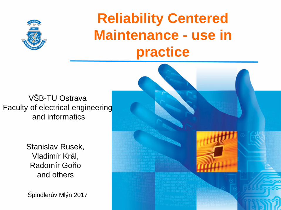
Categorization of DTS into groups
1989
4966
1333
0
765
184
3368
43257
71607
34278
349788
408507
0%
10%
20%
30%
40%
50%
60%
70%
80%
90%
100%
Number of DTS Total VO Total MOP Total MOO
A
B
C

Optimization of DTS maintenance cycle
Comparative graph of the maintenance cycls of individual DTS groups( Pro: kned = 500 ) s ú.p.
0
1000
2000
3000
4000
5000
6000
7000
8000
9000
10000
0 0,05 0,1 0,15 0,2 0,25 0,3 0,35 0,4
Optimal maintenance rate
Cos
ts (C
ZK)
C
B
A

Optimization of DTS maintenance cycle
• Total number of DTS - 8,613.
• Till 2004 standard maintenance in a cycle of 4 years.
• Division into 3 groups according to RCM:• A - 1,606 units, period of 4 years
• A - 4,940 units, period of 6 years
• A - 2,067 units, period of 8 years
• Reduction of dust nuisance by 31% per year.
• Given an average standard maintenance cost of CZK 3,022 for one DTS, this represents a total maintenance cost saving for all DTS in the DS, Moravia Region in the amount of CZK 2 millionper year.

22 kV linesDivision of the lines into sections

NMMO number of retail households connected to the given sectionNMOP number of retailers connected to the given sectionNVO number of wholesalers connected to the given sectionkMMO coefficient of retail households with value 1kMOP coefficient of retailers with value 5kVO coefficient of wholesalers with value 50kk weight coefficient of clientsI element load - current (A) kI weight coefficient of element load - currentV line section type - trunk V=5, main branch Vho=1, secondary branch Vpo=0.1Z possibility for output reserve for customers - without a reserve possibility Z = 1, remote controlled element Z=0.1, manually controlled element Z=0.5
Evaluation of the importance of the line
ZVkIkkNkNkNKredit I ))(( kVOVOMOPMOPMOOMOO

The importance of individual groups of line sections isdeterminant for enumeration of the costs upon unplannedoutage (failure to supply power) and has a direct impact onthe line section maintenance cycle.Using the mean values of the credit intervals of the individualline groups, determination of the importance multiples - VX isdone for the individual line section groups.
Credit intervals in groups
Group A max. > credits >= 50,000Group B 50,000 > credits >= 15,000Group C 15,000 > credits >= 2,000Group D 2,000 > credits >= 0

According to the limits given inthe previous table, the numberof sections in the individualgroups were determined.
Group A 289Group B 855Group C 224Group D 56
Due to the fact that the failure rateand financial flow data are related toa kilometer of the line, it isnecessary to determine the averagelength of the line per section andsubsequently the length of the line inthe individual groups.
Group A 1,637Group B 4,843Group C 1,269Group D 317
Determination of the number of sections

Cost function in the individual categories according to significance for faults, which can be impacted by
maintenance
0
1000
2000
3000
4000
5000
6000
7000
8000
9000
10000
11000
12000
0 0,05 0,1 0,15 0,2 0,25
Optimální intenzita údržby
Nákl
ady
(K)
D
C
BA
kned = 1

Cost function in the individual categories according to significance for faults, which can be impacted by
maintenance
kned = 24
0
2000
4000
6000
8000
10000
12000
14000
16000
18000
20000
22000
24000
26000
28000
30000
0 0,05 0,1 0,15 0,2 0,25 0,3 0,35 0,4
Optimální intenzita údržby
Nákl
ady
(K)
D
C
B
A
Optimální cyklus údržby: 4 roky
7 rok Skupina C a D mají optimální cyklus údržby do poruchy

Cost function in the individual categories according to importance for all faults
kned = 19
0
2000
4000
6000
8000
10000
12000
14000
16000
18000
20000
22000
24000
0 0,05 0,1 0,15 0,2 0,25 0,3 0,35 0,4
Optimální intenzita údržby
Nákl
ady
(K)
D
C
B
A
Optimální cyklus údržby: 4 roky
Skupina B, C a D mají optimální cyklus údržby do poruchy

Setting of the optimal sequence of elements for maintenance - 3 levels of maintenance
activity
Inspection and diagnostics
Inclusion in themaintenance plan for the following year
Immediateintervention
device 3
device 2
device 1
n 0tech
nica
l con
ditio
n
importance
n 0
d1
n 0
s
d2
n 0
s
d3
n 0

Setting of the optimal sequence of elements for maintenance - 4 levels of maintenance
activity
Inspection and diagnostics
Inclusion in maintenance planfor the following year
Immediateshut down
device 4
device 3
device 1
n 0
tech
nica
l con
ditio
n
importance
n 0
d1
n0
s
d3
n0
sd4
n0
Maintenanceasap
device 2
n 0
d2
n0
s
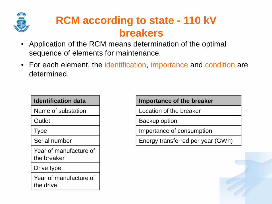
• Application of the RCM means determination of the optimal sequence of elements for maintenance.
• For each element, the identification, importance and condition are determined.
RCM according to state - 110 kV breakers
Identification dataName of substationOutletTypeSerial numberYear of manufacture of the breakerDrive typeYear of manufacture of the drive
Importance of the breakerLocation of the breakerBackup optionImportance of consumptionEnergy transferred per year (GWh)

RCM according to state - 110 kV breakers
Condition of the breakerDate of last intervention Number of drive motor hours (Mh)Date of last general maintenance of the contacts Tightness of extinction chamber
Number of CO after general maintenance of the contacts Tightness of drive system
Date of last general maintenance of the drive Evaluation of diagnostic tests
Number of CO after general maintenance of the drive
Condition of the metallic parts (corrosion, coating)
Date of assessment of technical condition Earthing condition
Climatic conditions Condition of the insulatorsNumber of CO
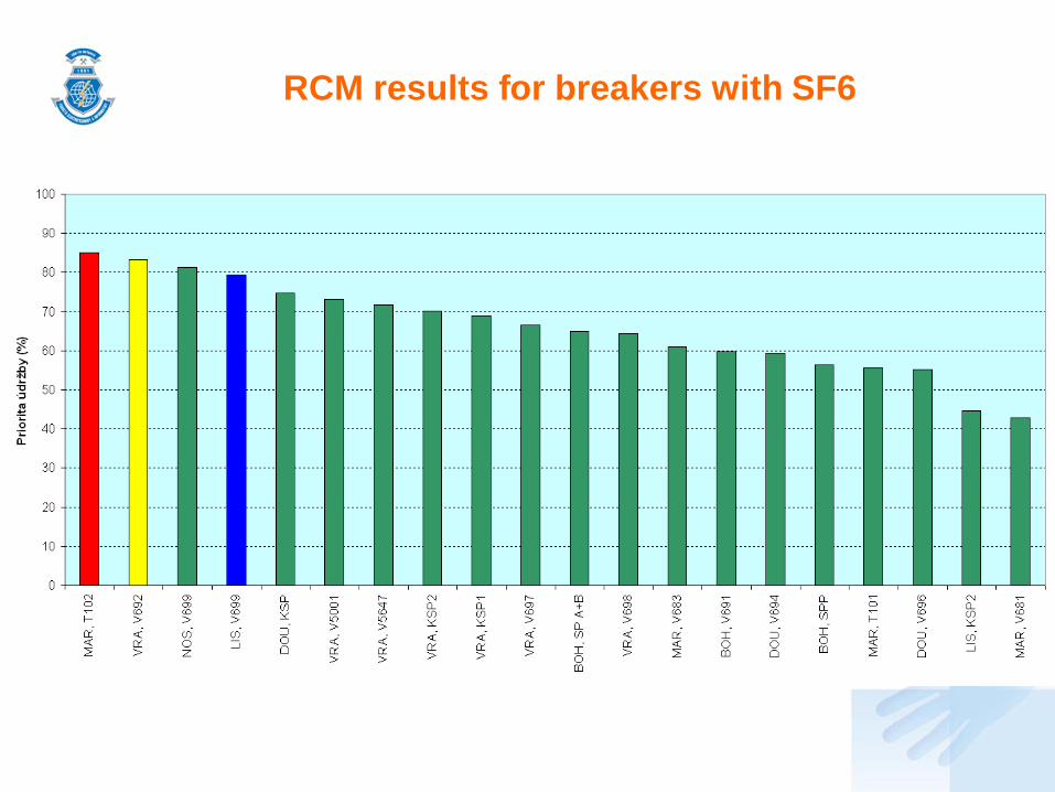
RCM results for breakers with SF6

RCM results for breakers with SF6

RCM according to state - 110 kV transformers
Identification dataREASAbbreviationTransformerYear of manufactureSerial numberSn (MVA)
Transformer conditionClimatic conditions Leaks
Date of standard maintenance or repair Condition of the control box and its equipment
Machine type CablesMachine age Number of switchoversAge of the branch switchgear Average hourly loadAge of the grommets Evaluation of diagnostic testsCondition of the vessel

RCM according to state - 110 kV transformers
Identification data
REAS Abbreviation
Transformer
Year of manufactu
reSerial number
East CR_HLIN T101 1998 154,408
East CR_HLIN T102 1999 154,409
East CR_TREM T101 1975 0941 026
Climatic conditions
Date of standard
maintenance or repair
Type of control
Year of manufacture of
the machine
Year of manufacture of the branch switchgear
Year of manufacture
of the grommets
Condition of the vessel
Leaks
1 7/25/2012 1 1998 1998 1998 1 1
1 7/20/2011 1 1999 1999 1999 1 1
1 5/10/2012 1 1975 1975 1975 1 2
1 3/22/2012 1 1996 1996 1996 1 1
1 4/17/2013 1 2008 2008 2008 1 1
1 3/26/2012 1 1999 1999 1999 1 1
1 5/10/2012 1 2007 2007 2007 1 1
Technical condition

RCM according to state - 110 kV transformers
Importance of the transformerTransferred energy (GWh)TR backup (%)HV backup (%)TR rise time (min)HV rise time (min)Credit
CreditNumber of connected retail householdsNumber of connected retailersNumber of connected wholesalersOperating hours

RCM according to state - 110 kV transformers
Importance
Transferred energy (GWh)
TR backup (%)
HV backup (%)
TR rise time (min)
HV rise time (min)
Credit
Number of connected
retail households
Number of connected retailers
Number of connected
wholesalers
Operating hours
75.02 100 90 5 120 30681 15991 2148 79 8704
111.29 100 90 5 120 30681 15991 2148 79 8717
59.00 100 100 5 120 22990 13005 1597 40 7337
52.89 100 100 5 120 31075 17065 2152 65 8547
97.21 100 100 5 120 31075 17065 2152 65 8665
69.05 100 100 5 120 31075 17065 2152 65 8705
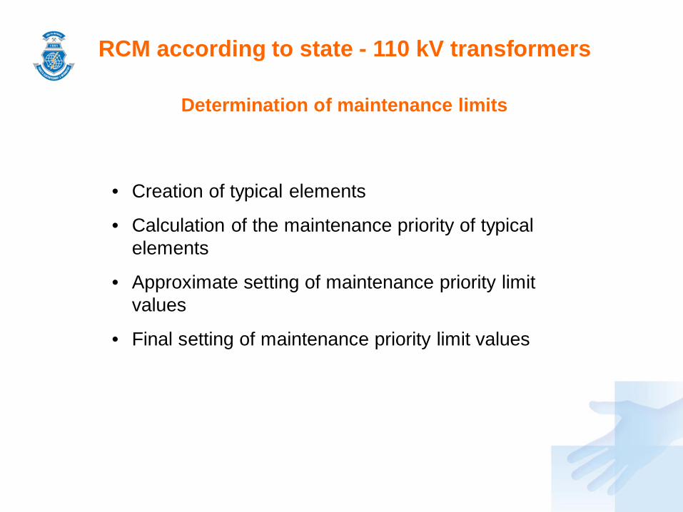
RCM according to state - 110 kV transformers
Determination of maintenance limits
• Creation of typical elements
• Calculation of the maintenance priority of typical elements
• Approximate setting of maintenance priority limit values
• Final setting of maintenance priority limit values

RCM according to state - 110 kV transformers
Example of typical elements creation
Number of elements Technical diagnostics Tightness of extinction
chamber
1. 100 100
2. 100 50
3. 100 25
4. 66 100
5. 66 50
6. 66 25
7. 33 100
8. 33 50
9. 33 25

RCM according to state - 110 kV transformers
72 typical transformers
Name of transformer Diagnostics Tightnes
s (leaks)
Time from last
standard maintenanc
e
Average load Age of transformer
T-Tr1 100 N/A 1 year 50-70% 10 years
T-Tr2 100 N/A 1 year 50-70% 30 years
T-Tr3 100 N/A 1 year above 90% 10 years
T-Tr4 100 N/A 1 year above 90% 30 years
T-Tr5 100 N/A 4 years 50-70% 10 years
T-Tr6 100 N/A 4 years 50-70% 30 years
T-Tr7 100 N/A 4 years above 90% 10 years
T-Tr8 100 N/A 4 years above 90% 30 years
··· ··· ··· ··· ··· ···
T-Tr65 33 large 1 year 50-70% 10 years
T-Tr66 33 large 1 year 50-70% 30 years
T-Tr67 33 large 1 year above 90% 10 years
T-Tr68 33 large 1 year above 90% 30 years
T-Tr69 33 large 4 years 50-70% 10 years
T-Tr70 33 large 4 years 50-70% 30 years
T-Tr71 33 large 4 years above 90% 10 years
T-Tr72 33 large 4 years above 90% 30 years

RCM according to state - 110 kV transformers
72 typical transformers – evaluation ranges
• Diagnostics 100% (1), 66% (0.66), 33% (0.33)• Tightness (leaks) no leaks (1), minor leaks (0.9),
big leaks (0.6). • Average load 50-70% (0.825), above 90% (0.5)• Age of transformer 10 years (0.95), 30 years (0.85)• Time from last standard maintenance 1 year (0.89), 4 years (0.57)

Maintenance priority for typical transformers of medium importance
Name of transformer Diagnostics Tightness (leaks)
Time from last
standard maintenanc
e
Average load
Age of transforme
r
Technical
condition
Importance Priority
T-Tr1 100 N/A 1 year 50-70% 10 years 69.6 40.00 33.3
T-Tr9 100 minor 1 year 50-70% 10 years 62.7 40.00 38.1
T-Tr2 100 N/A 1 year 50-70% 30 years 62.3 40.00 38.4
T-Tr10 100 minor 1 year 50-70% 30 years 56.1 40.00 42.8
T-Tr25 66 N/A 1 year 50-70% 10 years 46.0 40.00 49.8
T-Tr5 100 N/A 4 years 50-70% 10 years 44.2 40.00 51.0
T-Tr3 100 N/A 1 year above 90% 10 years 42.2 40.00 52.5
T-Tr17 100 bigger 1 year 50-70% 10 years 41.8 40.00 52.8
T-Tr33 66 minor 1 year 50-70% 10 years 41.4 40.00 53.0
T-Tr26 66 N/A 1 year 50-70% 30 years 41.1 40.00 53.2
T-Tr55 33 N/A 4 years above 90% 10 years 8.8 40.00 75.8
T-Tr69 33 bigger 4 years 50-70% 10 years 8.8 40.00 75.9
T-Tr67 33 bigger 1 year above 90% 10 years 8.4 40.00 76.2
T-Tr63 33 minor 4 years above 90% 10 years 8.0 40.00 76.4
T-Tr56 33 N/A 4 years above 90% 30 years 7.9 40.00 76.5
T-Tr70 33 bigger 4 years 50-70% 30 years 7.8 40.00 76.5
T-Tr68 33 bigger 1 year above 90% 30 years 7.5 40.00 76.8
T-Tr64 33 minor 4 years above 90% 30 years 7.1 40.00 77.0
T-Tr71 33 bigger 4 years above 90% 10 years 5.3 40.00 78.3
T-Tr72 33 bigger 4 years above 90% 30 years 4.7 40.00 78.7

RCM according to state - 110 kV transformers
Calculation of the maintenance priority of typical elements
000 10 -100-1 KK ii
iHVK
n
iiKTS
1
TSTS (%)1(%)100 KDKTSPr

RCM according to state - 110 kV transformers
Approximate maintenance priority values1st limit 2nd limit 3rd limit
Importance
min 58.6 - 60.1 68 - 69.3
medium 56.1 - 58.2 67.6 - 69.1 77 - 78.3
max 53 - 60.5 69.5 - 73.1 79.6 - 81.1
Resultant maintenance priority values
Level Maintenance priority Maintenance activity
1 Up to 57 do diagnostics and maintenance at set intervals
2 57 - 68.2 include in the maintenance plan for next year
3 68.2 - 77.8 plan maintenance as soon as possible; if the transformer has a 100% backup, shut it down immediately
4 Above 78.2 immediate shutdown

Calculation algorithm
Setting of input database parameters
Download
- technical state criteria- weights of the technical state criteria- significance criteria- weights of the significance criteria- auxiliary databases (DTS)- database of evaluation and limit values- maintenance priority limit values
Editing option
- weights of the technical state criteria- weights of the significance criteria- database of evaluation and limit values
Calculation
Visualization of results
Saving of results
Setting of calculation limit values

RCM according to state - 110 kV transformers
Number of transformers in the individual groups
REASTransformers Number in the maintenance
activity group
Total 1 2 3
East 71 67 4 0
West 56 48 8 0
North 76 69 7 0
Central 50 43 5 2
Moravia 89 78 9 2
Total 342 305 33 4

RCM according to state - 110 kV transformers
Sequence to maintenance for the East region
REAS Abbreviation
Transformer
Year of manufa
cture
Serial number
Sn [MVA]
Technical condition (%)
Diagnostics (%)
Significance (%)
Priority (%)
Sequence
Limit level
East PA_PASE T101 1990 0962 528 40 29.8 100 60.0 65.1 1 2
East PA_PASE T102 1993 0965 908 43 23.9 100 54.0 65.1 2 2
East TU_PORI T101 1972 938,023 25 29.7 100 54.0 62.1 3 2
East TU_PORI T103 1987 956415 40 43.2 100 60.0 58.4 4 2
East HK_HKJI T101 2009 968795 40 40.6 100 54.0 56.7 5 1
East RK_RYCH T103 1982 0944 589 40 48.7 100 60.0 55.6 6 1
East RK_RYCH T101 1998 929,802 25 39.3 100 48.0 54.4 7 1
East RK_RYCH T102 1967 929,801 40 48.4 100 54.0 52.8 8 1
East SY_SVIT T102 1994 921,229 40 39.8 66 39.8 50.0 9 1
East SM_SEMI T102 2005 968183 40 49.7 100 49.7 50.0 10 1
··· ··· ··· ··· ··· ··· ··· ··· ··· ··· ··· ···
East CR_TUNE T102 2008 462083 40 87.2 100 40.6 26.7 66 1
East UO_USTI T103 2000 932,922 25 70.6 100 21.1 25.3 67 1
East UO_JABL T102 1988 958404 25 73.4 100 20.4 23.5 68 1
East NA_POLI T102 1993 932,921 25 74.8 100 19.7 22.5 69 1
East NA_CEKO T102 1997 926,334 25 81.5 100 22.2 20.4 70 1
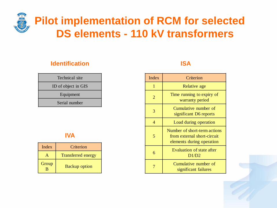
Pilot implementation of RCM for selected DS elements - 110 kV transformers
Identification
Technical site
ID of object in GIS
Equipment
Serial number
Index Criterion
1 Relative age
2 Time running to expiry of warranty period
3 Cumulative number of significant D6 reports
4 Load during operation
5Number of short-term actions
from external short-circuit elements during operation
6 Evaluation of state after D1/D2
7 Cumulative number of significant failures
ISA
Index Criterion
A Transferred energy
Group B Backup option
IVA

Pilot implementation of RCM for selected DS elements - 110 kV breakers
Identification ISA
IVA
Technical site
ID of object in GIS
Superior devices
Index Criterion
1 Fire extinguishing medium
2 Relative age
3 Time running to expiry of warranty period
4 Cumulative number of significant D6 reports
5 Evaluation of state after D1/D2
6 Number of operational switch-on instances
7 Index of short-circuit history
8 Cumulative number of significant failures
Index Criterion
A Significance in the network
Group B
Significant customers (A, B)
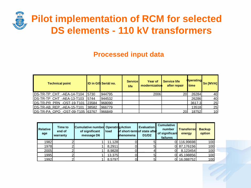
Pilot implementation of RCM for selected DS elements - 110 kV transformers
Processed input data
Relative age
Time toend of
warranty
Cumulative numberof significantmessage D6
Operatingload
Actionof short-term phenomena
Evaluationof state after
D1/D2
Cumulative number
of significantfailures
Transferred energy
Backupoption
1982 2 1 11,128 0 5 0 116,99698 1001978 2 1 8,2911 0 5 0 87,176156 1002005 2 1 8,9828 0 4 0 8,123454 1001995 2 1 13,375 0 5 0 45,198856 1001992 2 1 8,5797 0 5 0 16,088752 100
Technical point ID in GIS Seriál no. Servicelife
Year of modernization
Service lifeafter repair
Operatingtime Sn [MVA]
DS-TR-TP_CHT_-AEA-14-T104 5730 944795 2006 20 26284 40DS-TR-TP_CHT_-AEA-13-T103 5744 944532 26286 40DS-TR-PR_PRN_-OST-19-T101 23584 968090 3617,3 25DS-TR-AB_REP_-AEA-15-T101 38582 966779 13518 25DS-TR-PA_OPO_-OST-09-T105 63767 966849 20 18752 10
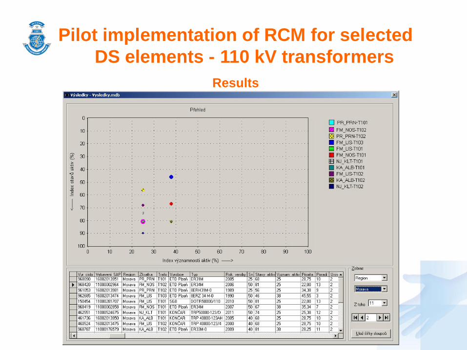
Pilot implementation of RCM for selected DS elements - 110 kV transformers
Results

Pilot implementation of RCM for selected DS elements - 110 kV transformers
Detailed results - asset conditions
Rel
ativ
e ag
e
Tim
e til
l lap
se o
f war
rant
y
Cum
ulat
ive
num
ber o
f sig
nific
ant
mes
sage
s D
6
Ope
ratin
g lo
ad
Act
ion
of s
hort-
ciru
it ph
enom
ena
Eva
luat
ion
of c
ondi
tion
afte
r D
1/D
2
Cum
ulat
ive
num
ber o
f sig
nific
ant
failu
res
Inde
x of
ass
et c
ondi
tions
(%)
75 100 90 100 100 82,5 100 55,687555 100 90 100 100 82,5 100 40,837575 100 90 100 100 100 100 67,5
62,5 100 90 100 100 82,5 100 46,4062562,5 100 90 100 100 82,5 100 46,40625
Relative age
Time till lapse
of warranty
Cumulative numberof signficantmessages D6
Operatingload
Action ofshort-circuit
phenomena
Evaluationof condition after D1/D2
Cumulative number ofsignificant
failures1982 2 1 11,128 0 5 01978 2 1 8,2911 0 5 02005 2 1 8,9828 0 4 01995 2 1 13,375 0 5 01992 2 1 8,5797 0 5 0

Pilot implementation of RCM for selected DS elements - 110 kV transformers
Detailed results - asset significance
Rok modernizace
Doba životnosti po oprav
Doba provozu Sn [MVA] enesená
energieMožnost
zálohování
2006 20 26284 40 116,99698 10026286 40 87,176156 100
3617,3 25 8,123454 10013518 25 45,198856 100
20 18752 10 16,088752 100
Rok
mod
erni
zace
Dob
a ži
votn
osti
po o
prav
Dob
a pr
ovoz
u
Sn
[MV
A]
Pen
esen
á en
ergi
e
Mož
nost
zál
ohov
ání
Inde
x vý
znam
nost
i akt
iv (%
)2006 20 26283,65 40 100 50 50
26286 40 75 50 37,53617,33 25 50 50 2513517,5 25 50 50 25
20 18752,17 10 50 50 25

Pilot implementation of RCM for selected DS elements - 110 kV transformers
Detailed results – resultant evaluation
Rok
mod
erni
zace
Dob
a ži
votn
osti
po o
prav
Dob
a pr
ovoz
u
Sn [M
VA]
Inde
x st
av a
ktiv
(%)
Inde
x vý
znam
nost
i akt
iv (%
)
Prio
rita
(%)
Poad
í
Úro
ve
2006 20 26283,65 40 55,6875 50 47,15625 5 226286 40 40,8375 37,5 48,33125 4 2
3617,33 25 67,5 25 28,75 10 213517,5 25 46,40625 25 39,296875 7 2
20 18752,17 10 46,40625 25 39,296875 7 2

RCM benefits
• reduction of workload
• optimal reliability and readiness of devices
• ensuring technical integrity of the devices
• reduction of maintenance costs and maintenance of the required readiness and reliability of the devices
• gradual creation of a reliability database
• centralization of device maintenance work flows
• definition of device maintenance strategy based on risk evaluation

• 2005 - periodical application of RCM in the planning of standard maintenance of the distribution transformer stations (DTS).
• 2005 - application of RCM according to the condition when planning general maintenance of selected 110 kV breakers.
• 2007 - application of RCM to 110 kV/HV transformers completed.
• 2014 - evaluation of transformers according to maintenance categories.
• 2016 - pilot implementation of RCM on the VHV and HV breakers, as well as the 110 kV/HV transformers.
Experience with RCM deploymentin the EZ Group

Thank you for your attention!
The paper was prepared with the support of the SGS grant (No. SP2017/54) and the TUCENET project (No.LO1404).