Embed Size (px)
DESCRIPTION
relaese notes for cfd-ace v 2013.2
Citation preview

7/18/2019 Release Notes V2013.2
http://slidepdf.com/reader/full/release-notes-v20132 1/42
ACE+ Suite V2013.2
Release Notes

7/18/2019 Release Notes V2013.2
http://slidepdf.com/reader/full/release-notes-v20132 2/42

7/18/2019 Release Notes V2013.2
http://slidepdf.com/reader/full/release-notes-v20132 3/42
ACE+ Suite V2013.2
Release Notes
7/18/2019 Release Notes V2013.2
http://slidepdf.com/reader/full/release-notes-v20132 4/42
©1997-2013 by ESI-Group
This ESI Group documentation is the confidential and proprietary product of ESI-Group, Inc. Anyunauthorized use, reproduction, or transfer of this manual is strictly prohibited. This documentation issubject to limited distribution and restricted disclosure.
CFD-ACE™, CFD-ACE+™, CFD-CADalyzer™, CFD-VIEW™, CFD-GEOM™, SimManager™, CFD-VisCART™, CFD-Micromesh™ and CFD-FASTRAN™ are registered trademarks of ESI-Group.
Portions of this product are owned by third-party software vendors.
Revision Information
The information in this guide applies to all current ESI CFD products until superseded by a newerversion of this guide.Published: September 2013UA/CFD_/12/24/00/D
Disclaimers
The documents and related know-how herein provided by ESI Group subject to contractual conditionsare to remain confidential. The CLIENT shall not disclose the documentation and/or related know-howin whole or in part to any third party without the prior written permission of ESI Group.
About ESI GROUPESI provides a world leading software editor for the numerical simulation of prototype andmanufacturing process engineering in applied mechanics. The key to ESI's success is the use ofrealistic material physics, providing "as good as real" virtual solutions, in order to replace the lengthytrial and error processes on real prototypes.
ESI has developed an extensive suite of coherent, industry-oriented applications to realisticallysimulate a product’s behavior during testing and real life use; to refine manufacturing processes fordesired product performance, and to evaluate the effect of the environment in which the product is
deployed.ESI’s products represent a unique collaborative and open environment for End-to-End VirtualPrototyping, thus eliminating the need for physical prototypes during product development. Thissolution allows a productivity gain, innovation acceleration and significantly reduced costs.For more information about ESI Group, visit www.esi-group.com.
About ESI CFDESI CFD is a technology leader in the field of advanced computational fluid dynamics simulationsoftware backed by more than 20 years of research-based knowledge throughout a wide range ofindustries. ESI CFD’s broad range of products and services provide all of the necessary tools foradvanced multiphysics analysis in a virtual prototype environment, significantly reducing time andexpense through comprehensive up-front modeling and simulation. Key focus areas includeaerospace, automotive, biomedical, fuel cells, MEMS, microfluidics, plasma and semiconductor.
Contact Information for ESI CFD
ESI CFD, Inc.6767 Old Madison Pike, Ste. 600Huntsville, AL 35806
Phone: (256) 713-4700 Fax: (256) 713-4799Software Support: [email protected] Sales: [email protected]

7/18/2019 Release Notes V2013.2
http://slidepdf.com/reader/full/release-notes-v20132 5/42
ACE+ Suite V2013.2 Release Notes v
Table of Contents
ACE+ Suite V2013.2 ............................................................................................................ 1
ACE+ Suite of Applications ............................................................................................. 1
Supported Platforms........................................................................................................ 1
Backward Compatibility ................................................................................................... 2 Running Older Versions .................................................................................................. 2
CFD-GEOM V2013.2 ............................................................................................................ 3
New Features and Improvements .................................................................................... 5 Corrected Problems ........................................................................................................ 9
Known Problems ............................................................................................................. 9
CFD-VisCART V2013.2 ...................................................................................................... 11
New Features and Improvements.................................................................................. 13
Corrected Problems ...................................................................................................... 16
Known Problems ........................................................................................................... 16
CFD-ACE+ V2013.2 ........................................................................................................... 17
New Features and Improvements.................................................................................. 19
Corrected Problems ...................................................................................................... 24
Known Problems ........................................................................................................... 25
ACE+ Suite V2013.1 .......................................................................................................... 27
V2013.1 – Corrected Problems ......................................................................................... 29
CFD-GEOM .................................................................................................................. 29
CFD-VisCART ............................................................................................................... 29
CFD-ACE+ .................................................................................................................... 29
CFD-VIEW .................................................................................................................... 30 SimManager .................................................................................................................. 30
ACE+ Suite V2013.0 .......................................................................................................... 31
V2013.0 – Corrected Problems ......................................................................................... 33
CFD-GEOM .................................................................................................................. 33 CFD-VisCART ............................................................................................................... 33
CFD-ACE+ .................................................................................................................... 34
CFD-CADalyzer ............................................................................................................ 34
CFD-VIEW .................................................................................................................... 34
SimManager .................................................................................................................. 34

7/18/2019 Release Notes V2013.2
http://slidepdf.com/reader/full/release-notes-v20132 6/42
Table of Contents
vi Release Notes ACE+ Suite V2013.2
7/18/2019 Release Notes V2013.2
http://slidepdf.com/reader/full/release-notes-v20132 7/42
ACE+ Suite V2013.2 Release Notes 1
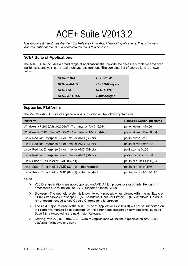
ACE+ Suite V2013.2This document introduces the V2013.2 Release of the ACE+ Suite of applications. It lists the new
features, enhancements and corrected issues in this Release.
ACE+ Suite of Applications
The ACE+ Suite includes a broad range of applications that provide the necessary tools for advancedmultiphysics analysis in a virtual prototype environment. The complete list of applications is shownbelow.
CFD-GEOM CFD-VIEW
CFD-VisCART CFD-CADalyzer
CFD-ACE+ CFD-TOPO
CFD-FASTRAN SimManager
Supported Platforms
The V2013.2 ACE+ Suite of applications is supported on the following platforms:
Platform Package Canonical Name
Windows XP/2003/Vista/2008/Win7 on Intel or AMD (32-bit) pc-windows-nt5-x86
Windows XP/2003/Vista/2008/Win7 on Intel or AMD (64-bit) pc-windows-nt5-x86_64
Linux RedHat Enterprise 6+ on Intel or AMD (32-bit) pc-linux-rhe6-x86
Linux RedHat Enterprise 6+ on Intel or AMD (64-bit) pc-linux-rhe6-x86_64
Linux RedHat Enterprise 5+ on Intel or AMD (32-bit) pc-linux-rhe5-x86
Linux RedHat Enterprise 5+ on Intel or AMD (64-bit) pc-linux-rhe5-x86_64
Linux Suse 11 on Intel or AMD (64-bit) pc-linux-suse11-x86_64
Linux Suse 10 on Intel or AMD (32-bit) - deprecated pc-linux-suse10-x86
Linux Suse 10 on Intel or AMD (64-bit) - deprecated pc-linux-suse10-x86_64
Notes
V2013.2 applications are not supported on AMD Athlon processors or on Intel Pentium IIIprocessors due to the lack of SSE2 support on these CPUs.
Browsers: The webhelp system is known to work properly when viewed with Internet Explorer6+ (MS-Windows), Netscape 6+ (MS-Windows, Linux) or Firefox 3+ (MS-Windows, Linux). Itis not recommended to use Google Chrome for this purpose.
The next major Release of the ACE+ Suite of Applications (V2014.0) will not be supported onthe platforms marked as deprecated. On the other hand, support on new platforms, such asSuse 12, is expected in the next major Release.
Starting with V2015.0, the ACE+ Suite of Applications will not be supported on any 32-bitplatforms (Windows or Linux).

7/18/2019 Release Notes V2013.2
http://slidepdf.com/reader/full/release-notes-v20132 8/42
ACE+ Suite V2013.2
2 Release Notes ACE+ Suite V2013.2
Like the previous versions, ACE+ Suite V2013.2 will be Intel®Cluster Ready!
Backward Compatibility
There are no known backward compatibility problems with the ACE+ Suite of Applications, except forthe issue related to CFD-GEOM V2006 (or earlier) scripts, as mentioned below.
Due to numerous changes to the core of CFD-GEOM in V2007.6 the “Python wrapped” functions alsochanged significantly. This made it impossible to retain backwards compatibility for Python scripts.This means that CFD-GEOM V2007.6 or later versions cannot process CFD-GEOM V2006 or earlierPython scripts. It is indeed an unfortunate side-effect and one that was not taken lightly but we feltthat it was necessary in order to build a better CFD-GEOM core. So if you plan to use CFD-GEOM
V2006 script files you have a couple of options:
1. Keep CFD-GEOM V2006 installed and run your V2006 scripts through that version. YourV2013.0 license will allow V2013.2 and all older versions (including V2006) to run. TheV2013.2 versions of CFD-ACE+ and CFD-FASTRAN will read and use V2006 CFD-GEOMgenerated DTF files with no problem.
2. Convert your CFD-GEOM V2006 script files to V2013.2 format. This is a manual process oftranslating the V2006 script file to make use of V2013.2 script language. In most cases it is
just a matter of replacing the function calls with equivalent V2013.2 syntax (and leaves allyour program control structure in place). ESI Group customer support staff can advise you onhow to do this.
Running Older Versions
The 2013.2 software can be installed with existing 2013.1, 2013.0, 2011.0, and earlier ESI softwaredirectories. You will continue to be able to use old and new versions of the software, which will allowas much time as needed for transition. If you install 2013.2 software with existing 2013.1, 2013.0,2011.0, or earlier software, you must remember to modify your PATH so that the newest UTILSdirectory, i.e. $ESI_HOME/2013.2/UTILS/bin, appears first in your PATH. Then you may run olderversions of the software using the –runver <version> option. For example, on Linux systems,assuming a Bourne-type shell:
% export PATH=$ESI_HOME/2013.2/UTILS/bin:$PATH (Bourne-type shell syntax)
% CFD-GEOM –runver 2011.0 (runs 2011.0 CFD-GEOM)
7/18/2019 Release Notes V2013.2
http://slidepdf.com/reader/full/release-notes-v20132 9/42
ACE+ Suite V2013.2 Release Notes 3
CFD-GEOM V2013.2
Release Notes

7/18/2019 Release Notes V2013.2
http://slidepdf.com/reader/full/release-notes-v20132 10/42
CFD-GEOM V2013.2
4 Release Notes ACE+ Suite V2013.2

7/18/2019 Release Notes V2013.2
http://slidepdf.com/reader/full/release-notes-v20132 11/42
CFD-GEOM V2013.2
ACE+ Suite V2013.2 Release Notes 5
New Features and Improvements
CFD-GEOM V2013.2 includes the following new features and improvements.
New Support for Analytic Surfaces
Previous versions of CFD-GEOM supported only those surfaces that were internally defined bysplines. During CAD import, any analytic surfaces encountered in the file were always converted tosplines. Starting with this Release, CFD-GEOM supports surfaces whose underlying representation isanalytic. Geometric and meshing algorithms involving analytic surfaces (e.g. planes, cylinders,spheres, etc.) are usually much faster and more robust because they can be computed analyticallyrather than iteratively. The following need special mention:
• When importing CAD models containing many analytic surfaces, a significant speedup isexpected (a 2-fold speedup has been observed in many cases)
• Significant speedup is expected during various geometric operations such as Booleanoperations
• Significant speedup is expected during surface meshing
Enhanced CAD import performance in V2013.2
Enhanced surface meshing performance in V2013.2
7/18/2019 Release Notes V2013.2
http://slidepdf.com/reader/full/release-notes-v20132 12/42
CFD-GEOM V2013.2
6 Release Notes ACE+ Suite V2013.2
Additionally, many of the geometric operations have been modified so that, when possible, analyticsurfaces will be generated instead of splines. The size of the GGD files may also be smaller whenthey contain analytic surface definitions instead of the traditional splines.
Enhanced Advanced Covering Tool
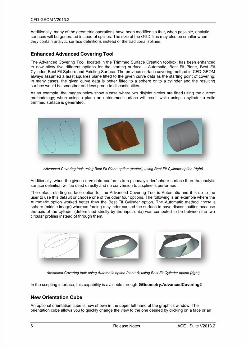
The Advanced Covering Tool, located in the Trimmed Surface Creation toolbox, has been enhancedto now allow five different options for the starting surface – Automatic, Best Fit Plane, Best FitCylinder, Best Fit Sphere and Existing Surface. The previous surface covering method in CFD-GEOMalways assumed a least squares plane fitted to the given curve data as the starting point of covering.In many cases, the given curve data is better fitted to a sphere or to a cylinder and the resultingsurface would be smoother and less prone to discontinuities.
As an example, the images below show a case where two disjoint circles are fitted using the currentmethodology; when using a plane an untrimmed surface will result while using a cylinder a validtrimmed surface is generated.
Advanced Covering tool: using Best Fit Plane option (center); using Best Fit Cylinder option (right)
Additionally, when the given curve data conforms to a plane/cylinder/sphere surface then the analyticsurface definition will be used directly and no conversion to a spline is performed.
The default starting surface option for the Advanced Covering Tool is Automatic and it is up to theuser to use this default or choose one of the other four options. The following is an example where the
Automatic option worked better than the Best Fit Cylinder option. The Automatic method chose asphere (middle image) whereas forcing a cylinder caused the surface to have discontinuities becausethe axis of the cylinder (determined strictly by the input data) was computed to be between the twocircular profiles instead of through them.
Advanced Covering tool: using Automatic option (center); using Best Fit Cylinder option (right)
In the scripting interface, this capability is available through GGeometry.AdvancedCovering2
New Orientation Cube
An optional orientation cube is now shown in the upper left hand of the graphics window. Theorientation cube allows you to quickly change the view to the one desired by clicking on a face or an

7/18/2019 Release Notes V2013.2
http://slidepdf.com/reader/full/release-notes-v20132 13/42
CFD-GEOM V2013.2
ACE+ Suite V2013.2 Release Notes 7
arrow. The arrows are only visible in a primary view such as front, top, bottom, etc. The images belowshow the orientation cube.
New Orientation Cube
Enhanced Solid Extrusion and Revolution Tool
The solid extrusion and revolution tools have been enhanced to now optionally generate solids, i.e.,
unstructured domains; users need to simply activate the “Create Solids” option in these tools. Theearlier versions of these tools only created surfaces.
‘Create Solids’ option in the Solid Extrusion tool
Enhanced Graphical Feedback during Sketching
When the construction plane is active along with the point creation option then many of the interactivegeometry creation tools such as lines, three point circles/arcs, two point circles, etc. will provide anenhanced feedback during the generation process. An origin of the plane will be indicated by showingtwo direction vectors corresponding to the U and V parametric directions on the plane, and when themouse is at a value such that it corresponds to a U or V value of zero then a blue indicator will be
displayed. Dashed lines will show when a subsequent point is at the same parametric value as aprevious point and when interactively sketching a two point or three point circle/arc.

7/18/2019 Release Notes V2013.2
http://slidepdf.com/reader/full/release-notes-v20132 14/42
CFD-GEOM V2013.2
8 Release Notes ACE+ Suite V2013.2
Enhanced Face Projection
The face projection methods (used in the Project Face Tool) have been optimized for speed,specifically in cases where a face is projected onto multiple surfaces. Consequently, compared to theprevious version, the Normal projection method may now be up to thirty times faster and the Closestpoint method up to four times faster.
Miscellaneous Improvements
The construction plane graphics has been modified such that in most views it will alwaysremain visible.
The Snap option has been moved next to the point creation option in the entity bar.
For very large models, graphics performance is expected to be better than in the previousversion.

7/18/2019 Release Notes V2013.2
http://slidepdf.com/reader/full/release-notes-v20132 15/42
CFD-GEOM V2013.2
ACE+ Suite V2013.2 Release Notes 9
Corrected Problems
The following are the corrected issues in this release.
When generating a hybrid mesh, if the triangle mesher was invoked on a structured faceentity bounding a semi-structured domain, it would cause the domain's mesh to be destroyedand not rebuilt. This would lead to errors during DTF output. This issue has been corrected.
Due to certain improvements, better cell quality can be expected for certain semi-structuredmeshes.
Known Problems
These are the known serious problems with the latest release. Some or all of these problems may becorrected in a future release.
Updating Existing DTF Files: Updating existing DTF files from models containing polyhedralzones (i.e. coarsened blocks) is not currently supported. Only “fresh” DTF files may be writtenfrom models containing such grid types.
Undo Operations in the Edge Editor : Undo is unavailable in the Edge editor. If the userquits the edge editing session at any point where the system is in an error state (faces withopposing edges without the same number or grid points) CFD-GEOM will reinstate the gridsystem to the last known “good” state.

7/18/2019 Release Notes V2013.2
http://slidepdf.com/reader/full/release-notes-v20132 16/42
CFD-GEOM V2013.2
10 Release Notes ACE+ Suite V2013.2
7/18/2019 Release Notes V2013.2
http://slidepdf.com/reader/full/release-notes-v20132 17/42
ACE+ Suite V2013.2 Release Notes 11
CFD-VisCART V2013.2
Release Notes

7/18/2019 Release Notes V2013.2
http://slidepdf.com/reader/full/release-notes-v20132 18/42
CFD-VisCART V2013.2
12 Release Notes ACE+ Suite V2013.2
7/18/2019 Release Notes V2013.2
http://slidepdf.com/reader/full/release-notes-v20132 19/42
CFD-VisCART V2013.2
ACE+ Suite V2013.2 Release Notes 13
New Features and Improvements
CFD-VisCART V2013.2 includes the following new features and improvements.
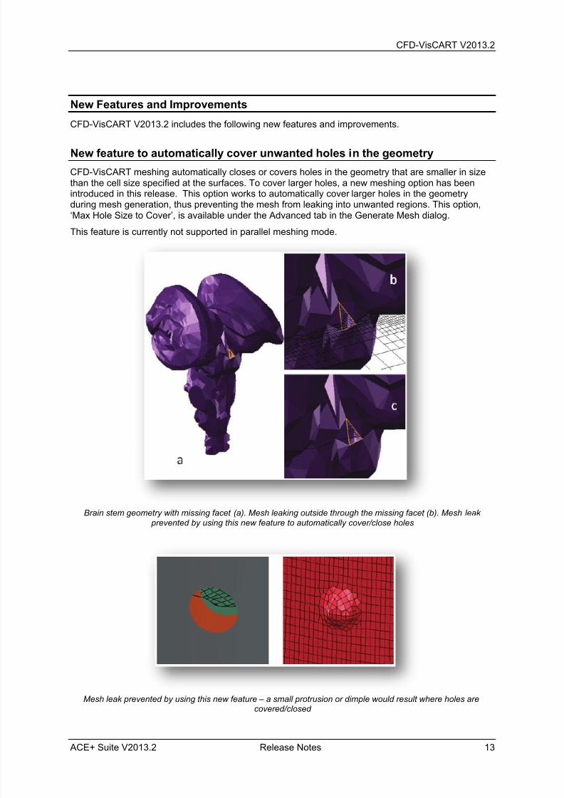
New feature to automatically cover unwanted holes in the geometry
CFD-VisCART meshing automatically closes or covers holes in the geometry that are smaller in sizethan the cell size specified at the surfaces. To cover larger holes, a new meshing option has beenintroduced in this release. This option works to automatically cover larger holes in the geometryduring mesh generation, thus preventing the mesh from leaking into unwanted regions. This option,‘Max Hole Size to Cover’, is available under the Advanced tab in the Generate Mesh dialog.
This feature is currently not supported in parallel meshing mode.
Brain stem geometry with missing facet (a). Mesh leaking outside through the missing facet (b). Mesh leak
prevented by using this new feature to automatically cover/close holes
Mesh leak prevented by using this new feature – a small protrusion or dimple would result where holes arecovered/closed

7/18/2019 Release Notes V2013.2
http://slidepdf.com/reader/full/release-notes-v20132 20/42
CFD-VisCART V2013.2
14 Release Notes ACE+ Suite V2013.2
New option to write out multiple cell groups with Single Domain mesher
When using the single domain mesher, a new option, ‘Write Separate Cell Group into DTF’, has beenintroduced for Box, Sphere and Cylinder mesh sources. When this option is selected for a source, allcells generated within the source are saved into a separate cell group (or Volume Condition) withinthe DTF. This option thus introduces a multiple volume mesh capability for the single domain mesher.
Typical applications for this capability would include writing out separate Volume Conditions forradiator and condenser volumes in a vehicle underhood mesh, modeling simpler geometries inelectronic components, among others.
As this capability is simply putting cells within a source into a separate cell group and there is noprojection or conformity to mesh source shape curvatures, the boundary surfaces of these cell groups(interfaces) can be jagged/stair-stepped in nature.
Radiator modeled using separate cell group option in CFD-VisCART and VC-based heat source in CFD-ACE+
A power supply box mock-up generated using separate cell group option for box, sphere and cylinder sources –no geometries. Simulation results from CFD-ACE+

7/18/2019 Release Notes V2013.2
http://slidepdf.com/reader/full/release-notes-v20132 21/42
CFD-VisCART V2013.2
ACE+ Suite V2013.2 Release Notes 15
New Shrink-wrapping option to generate cells of the exact specified size
In earlier versions, the shrink-wrap meshing algorithm would make sure that the cell generated at thesurfaces would be equal to or smaller in size than the specified ‘Maximum Mesh Size’. In most casesthough, the size of the cells would end up being smaller than the specified value. The reason behindthis is the fact that CFD-VisCART is a Cartesian based mesher where cells are generated by splitting
the bounding box (in X, Y and Z directions) successively into smaller and smaller cells, each timeexactly into half. In other words, if a bounding is 40 units long in a particular coordinate direction, cellsin the mesh can have sizes of 20, 10, 5, 2.5 and so on in that direction. Thus, if a user specifies avalue of 8 for ‘Maximum Mesh Size’, they would end up getting a size of 5.
Although this behavior stays the same in this release, a new option, ‘Adjust Bounding Box to Fit’ hasbeen introduced. When this option is selected, the specified size will be honored by automaticallychanging the size of the bounding box in all three coordinate directions – such that successivesplitting of the bounding box arrives at the specified value.
This option is available under the Mesh Refinement tab in the Generate Mesh dialog, when Shrink-Wrap meshing option is selected.
Shrink-Wrap surface mesh: Cells more uniform and as specified
New Cubic Bounding Box option
To make it easier to set up cubic bounding boxes (X span = Y span = Z span), a new ‘Cubic shape’bounding box option has been introduced in this release. This option is available in the Bounding BoxSetting dialog, when the Bounding Box Type is set to Box.
.
Effect of activating the ‘Cubic shape’ bounding box option

7/18/2019 Release Notes V2013.2
http://slidepdf.com/reader/full/release-notes-v20132 22/42
CFD-VisCART V2013.2
16 Release Notes ACE+ Suite V2013.2
Corrected Problems
There are no corrected problems in this release.
Known Problems
These are the known serious problems with the latest release. Some or all of these problems may becorrected in a future release.
Projected Single Domain mesher takes much longer to complete mesh generation if ‘FeaturePreservation’ is activated and the final mesh quality may not be as good as the one generatedwithout ‘Feature Preservation’.
The Multi Domain mesher may encounter problems in handling a domain interface if twosurfaces are present at that location but they don’t match exactly.

7/18/2019 Release Notes V2013.2
http://slidepdf.com/reader/full/release-notes-v20132 23/42
ACE+ Suite V2013.2 Release Notes 17
CFD-ACE+ V2013.2
Release Notes

7/18/2019 Release Notes V2013.2
http://slidepdf.com/reader/full/release-notes-v20132 24/42
CFD-ACE+ V2013.2
18 Release Notes ACE+ Suite V2013.2
7/18/2019 Release Notes V2013.2
http://slidepdf.com/reader/full/release-notes-v20132 25/42
CFD-ACE+ V2013.2
ACE+ Suite V2013.2 Release Notes 19
New Features and Improvements
CFD-ACE+ Solver
CFD-ACE+ Solver V2013.2 includes the following new features and improvements.
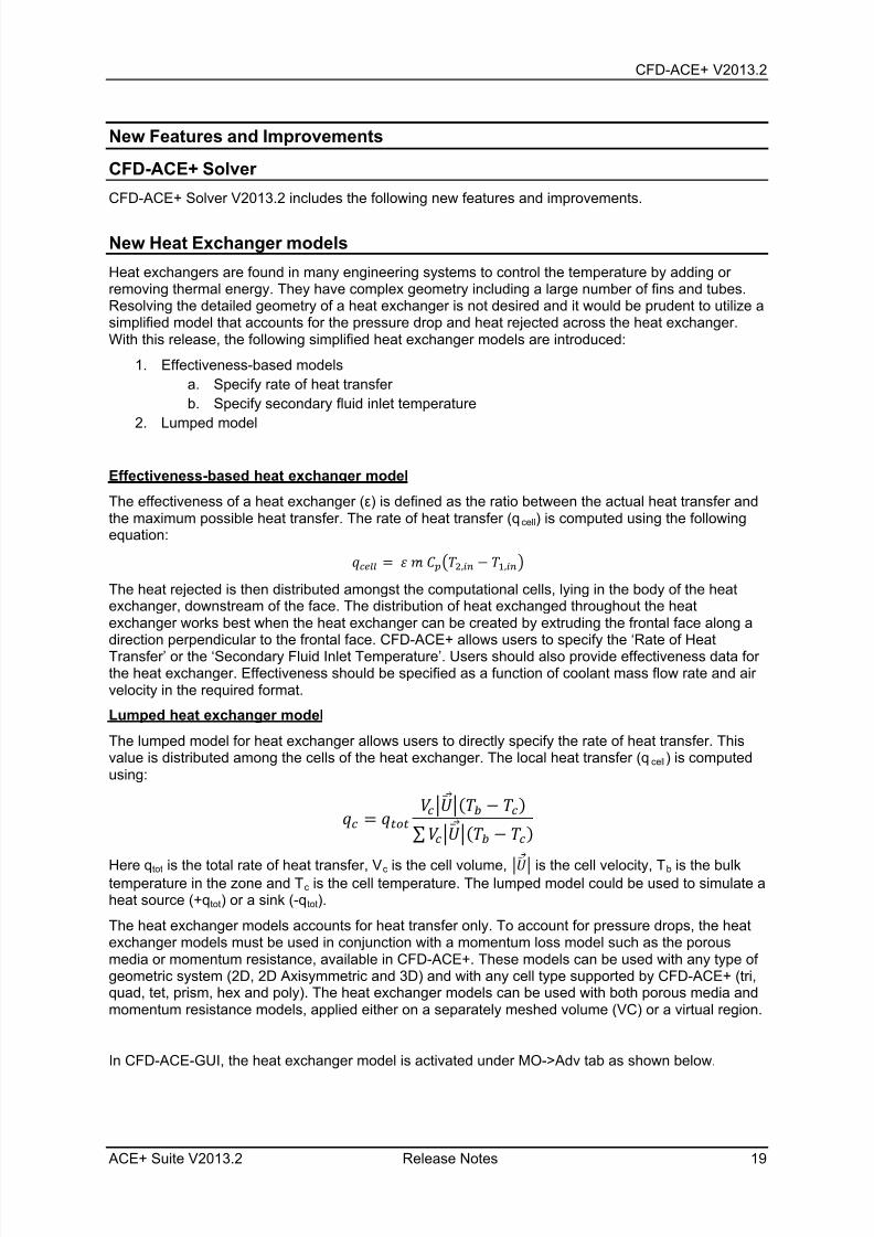
New Heat Exchanger models
Heat exchangers are found in many engineering systems to control the temperature by adding orremoving thermal energy. They have complex geometry including a large number of fins and tubes.Resolving the detailed geometry of a heat exchanger is not desired and it would be prudent to utilize asimplified model that accounts for the pressure drop and heat rejected across the heat exchanger.With this release, the following simplified heat exchanger models are introduced:
1. Effectiveness-based models
a. Specify rate of heat transfer
b. Specify secondary fluid inlet temperature
2. Lumped model
Effectiveness-based heat exchanger model
The effectiveness of a heat exchanger (ε) is defined as the ratio between the actual heat transfer andthe maximum possible heat transfer. The rate of heat transfer (qcell) is computed using the followingequation:
= ̇ �2, − 1,
The heat rejected is then distributed amongst the computational cells, lying in the body of the heatexchanger, downstream of the face. The distribution of heat exchanged throughout the heatexchanger works best when the heat exchanger can be created by extruding the frontal face along adirection perpendicular to the frontal face. CFD-ACE+ allows users to specify the ‘Rate of HeatTransfer’ or the ‘Secondary Fluid Inlet Temperature’. Users should also provide effectiveness data forthe heat exchanger. Effectiveness should be specified as a function of coolant mass flow rate and airvelocity in the required format.
Lumped heat exchanger model
The lumped model for heat exchanger allows users to directly specify the rate of heat transfer. Thisvalue is distributed among the cells of the heat exchanger. The local heat transfer (qcell) is computedusing:
= ( − )
∑ ( − )
Here qtot is the total rate of heat transfer, Vc is the cell volume, is the cell velocity, Tb is the bulktemperature in the zone and Tc is the cell temperature. The lumped model could be used to simulate aheat source (+qtot) or a sink (-qtot).
The heat exchanger models accounts for heat transfer only. To account for pressure drops, the heatexchanger models must be used in conjunction with a momentum loss model such as the porousmedia or momentum resistance, available in CFD-ACE+. These models can be used with any type ofgeometric system (2D, 2D Axisymmetric and 3D) and with any cell type supported by CFD-ACE+ (tri,quad, tet, prism, hex and poly). The heat exchanger models can be used with both porous media andmomentum resistance models, applied either on a separately meshed volume (VC) or a virtual region.
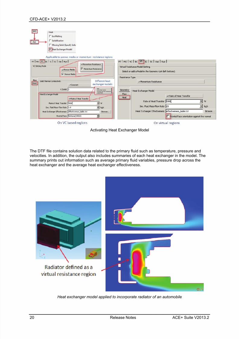
In CFD-ACE-GUI, the heat exchanger model is activated under MO->Adv tab as shown below.
7/18/2019 Release Notes V2013.2
http://slidepdf.com/reader/full/release-notes-v20132 26/42
CFD-ACE+ V2013.2
20 Release Notes ACE+ Suite V2013.2
Activating Heat Exchanger Model
The DTF file contains solution data related to the primary fluid such as temperature, pressure andvelocities. In addition, the output also includes summaries of each heat exchanger in the model. Thesummary prints out information such as average primary fluid variables, pressure drop across theheat exchanger and the average heat exchanger effectiveness.
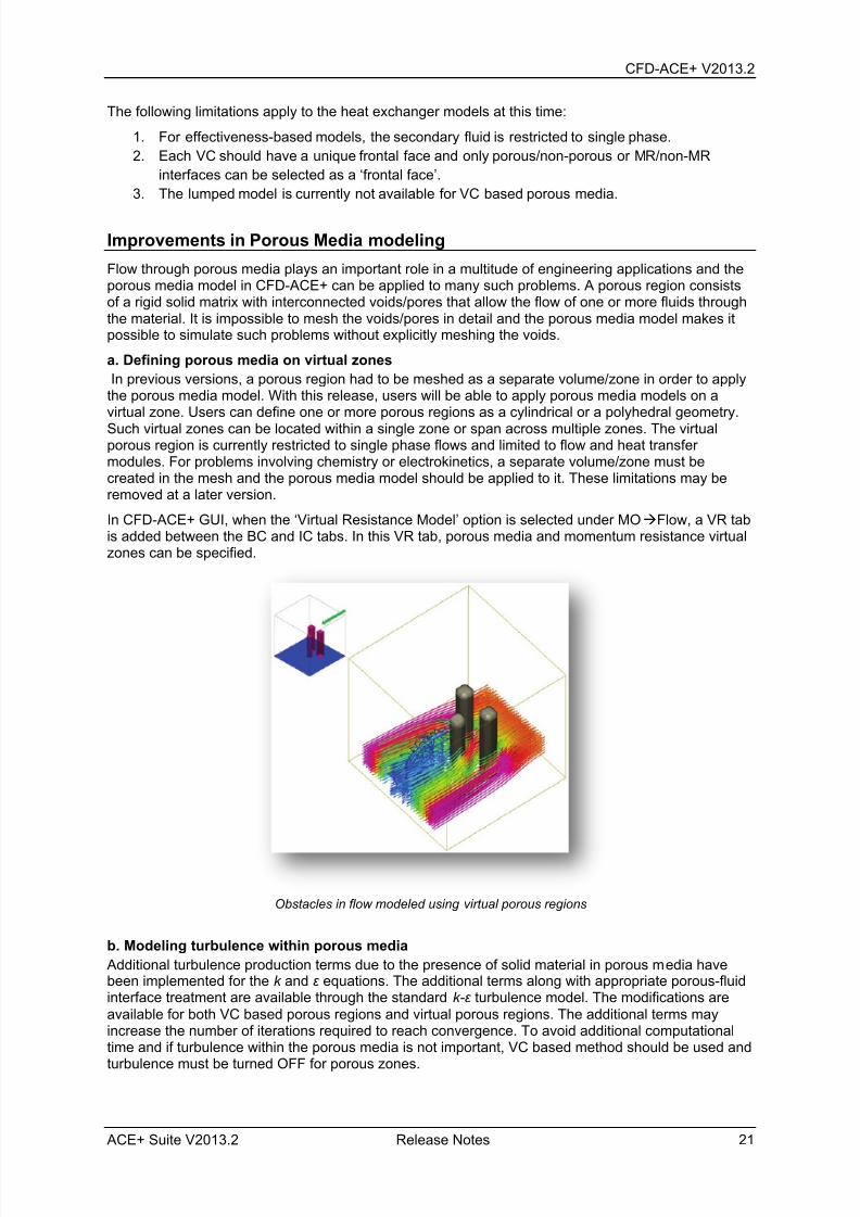
Heat exchanger model applied to incorporate radiator of an automobile
7/18/2019 Release Notes V2013.2
http://slidepdf.com/reader/full/release-notes-v20132 27/42
CFD-ACE+ V2013.2
ACE+ Suite V2013.2 Release Notes 21
The following limitations apply to the heat exchanger models at this time:
1. For effectiveness-based models, the secondary fluid is restricted to single phase.
2. Each VC should have a unique frontal face and only porous/non-porous or MR/non-MR
interfaces can be selected as a ‘frontal face’.
3. The lumped model is currently not available for VC based porous media.
Improvements in Porous Media modeling
Flow through porous media plays an important role in a multitude of engineering applications and theporous media model in CFD-ACE+ can be applied to many such problems. A porous region consistsof a rigid solid matrix with interconnected voids/pores that allow the flow of one or more fluids throughthe material. It is impossible to mesh the voids/pores in detail and the porous media model makes itpossible to simulate such problems without explicitly meshing the voids.
a. Defining porous media on virtual zones
In previous versions, a porous region had to be meshed as a separate volume/zone in order to applythe porous media model. With this release, users will be able to apply porous media models on avirtual zone. Users can define one or more porous regions as a cylindrical or a polyhedral geometry.
Such virtual zones can be located within a single zone or span across multiple zones. The virtualporous region is currently restricted to single phase flows and limited to flow and heat transfermodules. For problems involving chemistry or electrokinetics, a separate volume/zone must becreated in the mesh and the porous media model should be applied to it. These limitations may beremoved at a later version.
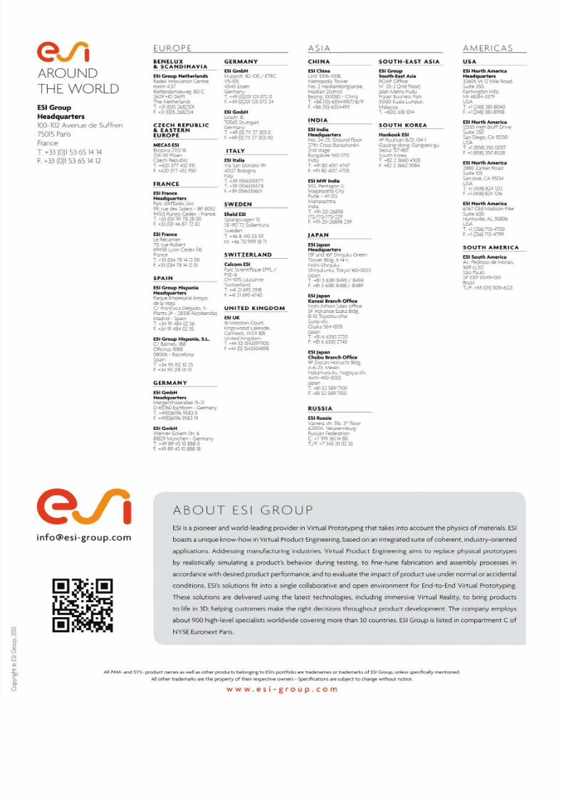
In CFD-ACE+ GUI, when the ‘Virtual Resistance Model’ option is selected under MOFlow, a VR tabis added between the BC and IC tabs. In this VR tab, porous media and momentum resistance virtualzones can be specified.
Obstacles in flow modeled using virtual porous regions
b. Modeling turbulence within porous media
Additional turbulence production terms due to the presence of solid material in porous media havebeen implemented for the k and ε equations. The additional terms along with appropriate porous-fluidinterface treatment are available through the standard k-ε turbulence model. The modifications areavailable for both VC based porous regions and virtual porous regions. The additional terms mayincrease the number of iterations required to reach convergence. To avoid additional computationaltime and if turbulence within the porous media is not important, VC based method should be used and
turbulence must be turned OFF for porous zones.

7/18/2019 Release Notes V2013.2
http://slidepdf.com/reader/full/release-notes-v20132 28/42
CFD-ACE+ V2013.2
22 Release Notes ACE+ Suite V2013.2
Velocity profile in a composite channel
Comparison of turbulent viscosity within porous regions
Comparison of turbulent thermal conductivity within porous regions

7/18/2019 Release Notes V2013.2
http://slidepdf.com/reader/full/release-notes-v20132 29/42
CFD-ACE+ V2013.2
ACE+ Suite V2013.2 Release Notes 23
New species concentration based electrolyte conductivity for Electroplating
In Electroplating processes, local species concentration affects the local electrical conductivity of theelectrolyte, which in turn affects the deposition or etching rates. In this release, an option to specifyelectrical conductivity as a function of species concentration has been introduced. The effect of usingthis option is demonstrated with an Electroplating simulation example below.
This new option is available in CFD-ACE+ GUI, under VCE/MElectrical Conductivity.
Electroplating simulation: Electric field in the electrolyte with constant conductivity (left); with conductivity as afunction of species concentration (right)
New User Defined Subroutine option for Momentum and Thermal Slip
In earlier versions, the Slip Walls feature would use the first-order (Maxwell) slip model. In this newrelease, an additional User-Defined Slip option has been introduced. Users can use this option tospecify their own velocity and thermal slip formulations through a user subroutine. As an example, thisoption could be used to specify higher order slip profiles.
This new option is available in CFD-ACE+ GUI, under MO AdvSlip Walls.
New Surface Pressure output files for coupling with VA One and other third-party software
This output option is available for both steady and transient flow simulations and writes out Pressuredata for the selected boundaries into CGNS format files. These output files can then be used as inputfiles for ESI’s Vibro-Acoustic simulation software, VA One, and for other (structural, noise, vibration,etc.) software.
Surface pressure load source in VA One after importing surface pressure output files from CFD-ACE+

7/18/2019 Release Notes V2013.2
http://slidepdf.com/reader/full/release-notes-v20132 30/42
CFD-ACE+ V2013.2
24 Release Notes ACE+ Suite V2013.2
Corrected Problems
The following are the corrected issues in this release.
GUI
o For Grid Deformation cases, when ‘Follow Leader Node’ option (under Constrained
Displacement) is selected, the BC selection list would not be properly sorted. Thisissue has been corrected and now the BCs are sorted by Name and Key number.
o For Stress cases, when using the ‘Setup Point Loads’ option, the nodes were listedlexicographically (1,10,2,20,…). The listing has now been made numerical(1,2,10,20,…) and thus more convenient.
o Certain parameters related to Kamal Correlation (under MOVOFCuring Reaction)have been renamed and reorganized for better clarity.
o The VCGeneral setting mode has been renamed to VCGrid Deformation and isshown only when the ‘User Sub(ugrid)’ option under MODeform is selected.
o The occasional GUI crash after scripting with spray injectors, macroparticles, fans,MRFs and momentum resistances has been fixed.
o Drawing of 2D and 3D polyhedral momentum resistance shapes has been correctedto accurately project the user-specified points onto the central line (2D) or centralplane (3D).
o The Solver Output window would occasionally get hidden if it was moved off-screenintentionally or if the user's desktop size was reduced. Also, if the "View Output"button was clicked multiple times, additional windows were opened for the same file.Now, when "View Output" is clicked and the Output window is not open, the OutputWindow is shown in its last position. However, if "View Output" is cl icked while theOutput window is open, the Output window position is reset to be centered on theapplication.
o The display of table data, such as Monitor Points, which could be incorrect
immediately after editing (when the model was scaled or used non-standard units),has been corrected.
o The VC based Turbulence activation option was not being read correctly from theDTF file. This issue has been corrected.
o For Spray and Magnetic cases, the section ‘Magnetic Tractive Force’ underMOSpray has been renamed ‘Magnetophoresis’. Also, the ‘Individual Particle’option (which would previously fail) has been corrected such that volumetricsusceptibility can be set on each injector.
o Certain Progress Bar display issues have been corrected.
o On certain Windows machines, saving DTF files to certain folders (for example,Desktop) would not be allowed. This issue has been corrected.
o Issues related to script warnings and errors not being displayed have been corrected.
o Display and dumping of script commands for spray injectors, macroparticles, fans,MRFs and momentum resistances are now disabled when the corresponding controls(modules or higher level controls) are turned OFF.
o GUI would crash when switching between two cases with mismatched number of tabs(one example of such a situation would be if one of the cases had the Spray moduleON leading to an additional ‘Inj’ tab). This issue has been corrected.
o When using the ‘Dump Script’ feature with “Exclude all defaults in the script file”option, certain lists (like the Follower Node list in Grid Deformation cases) were notbeing dumped correctly. This issue has been corrected.
o The GuiBC.Set script function has been corrected to allow “Shared/BC_Type”property to be set for a group of BCs that do not already have the same BC Type.

7/18/2019 Release Notes V2013.2
http://slidepdf.com/reader/full/release-notes-v20132 31/42
CFD-ACE+ V2013.2
ACE+ Suite V2013.2 Release Notes 25
Known Problems
The following are the known serious problems with this release. Some or all of these problems maybe corrected in a future release.
Solver
o DSMC simulations may not work properly except for very simple cases.
o The solver stops as soon as any macroparticle leaves the domain through an outlet.
o There are intermittent memory leak problems when the chimera module is used withthe flow and turbulence modules.
o In some situations, there may be a slight increase in the total pressure across anarbitrary interface.
o Robustness of parallel computation for Plasma simulations needs to be improved.
o When solving for heat transfer, the COND_IN and COND_OUT values reported in theHeat Transfer Summary for conjugate interfaces will not be accurate, if the cells nextto these conjugate interfaces are non-orthogonal.
o The Solver may fail to simulate certain electroplating cases that involve Cyclic BCs.
o If faces of a processor interface coincide with faces of a Fluid-Fluid interface on whicha Spray Boundary Injector is specified, then parcels will be injected twice from thesefaces.
o Heat Exchanger summary incorrect for parallel runs.
o Energy summary incorrect for parallel runs.
o Hotspots with heat exchanger models and high flow resistances.
GUI
o Importing a NASTRAN file may take longer on RedHat Enterprise 6 compared toother platforms.
o Drag-and-drop does not work on Windows 64-bit systems.

7/18/2019 Release Notes V2013.2
http://slidepdf.com/reader/full/release-notes-v20132 32/42
CFD-ACE+ V2013.2
26 Release Notes ACE+ Suite V2013.2

7/18/2019 Release Notes V2013.2
http://slidepdf.com/reader/full/release-notes-v20132 33/42
ACE+ Suite V2013.2 Release Notes 27
ACE+ Suite V2013.1
Release Notes

7/18/2019 Release Notes V2013.2
http://slidepdf.com/reader/full/release-notes-v20132 34/42
ACE+ V2013.1
28 Release Notes ACE+ Suite V2013.2

7/18/2019 Release Notes V2013.2
http://slidepdf.com/reader/full/release-notes-v20132 35/42
ACE+ Suite V2013.2 Release Notes 29
V2013.1 – Corrected Problems
The following applies to users upgrading to V2013.2 directly from V2013.1 release version.
CFD-GEOM
The V2013.1 Patch3 Release included corrections for the following software issues.
A very specific issue, related to projection of a face onto a sphere geometry made of twotrimmed surfaces, has been corrected. Earlier, only part of the face would get projected.
CFD-VisCART
The following are the corrected issues in this patch release.
In a very specific set of cases, if mesh generation would fail, it would combine all the patchesof the model into one patch in the active CFD-VisCART window. At this point, if the user
would save the VGD, it would overwrite the original VGD with this single patch VGD. A propererror message is now written out (explaining the reason why mesh generation failed) and arestore procedure has been implemented to prevent merging of patches.
In certain cases, boundary layer generation on bounding box patches would fail leading to an“internal error” message. This issue has been corrected.
In scripting, the ‘define_box_source_l’ command would not honor the user specified boxsource name. This issue has been corrected.
VGD files generated in parallel meshing mode would include some extra records which wouldcreate problems during later serial import. This issue has been corrected.
For cases using the Octree meshing approach, the mesh would be refined to a level greaterthan what was specified. This issue has been corrected.
In certain multi domain meshes, the expected mesh refinement due to local domain cell sizespecification was not observed. This issue has been corrected.
Certain Parasolid files could get imported with incorrect orientation. This issue has beencorrected.
On clicking the ‘Suppressed’ column header in the Domain Explorer, the list would not getsorted/ordered correctly. This issue has been corrected.
The CFD-GEOM, CFD-VIEW and CFD-ACE-GUI launch icons in the CFD-VisCART Toolbardid not work properly. This issue has been corrected.
In a very limited number of cases, writing the mesh in DTF format would result in a programcrash. This issue has been corrected.
CFD-ACE+
The V2013.1 Patch3 Release included corrections for the following software issues.
Solver
o ‘Override General Output Controls’ settings (under OutSummaries) were notworking correctly for Species Summary. This issue has been corrected.
o For cases with a large number of boundaries and being run in parallel mode, a bufferrelated issue would be encountered in some instances during Radiation Summary
output. This would result in the termination of the Solver processes. This issue hasbeen corrected.

7/18/2019 Release Notes V2013.2
http://slidepdf.com/reader/full/release-notes-v20132 36/42
ACE+ V2013.1
30 Release Notes ACE+ Suite V2013.2
o In very rare cases, where the Output file (filename.out) ends up being very large insize (several GBs), the CFD-SOLVER process could start consuming a large amountof memory when the solution terminates. This issue has been corrected.
o Restarting Electroplating simulations (that have Heat module activated) would resultin NaN being encountered for Enthalpy residuals. This issue has been corrected.
o Using the Monte Carlo Radiation model would produce "Input Error: Incorrect ncuts"warning messages (in the command line output) and the solution would likely beincorrect. This issue has been corrected.
o An error in the calculation of the Stream Function has been corrected
GUI
o A new setting called “Temperature Interpolation” is available under SC AdvHeatTransfer. This setting and its available options ensure proper interpolation of nodalTemperature data in the peripheral regions of zones.
CFD-VIEW
The V2013.1 Patch3 Release included corrections for the following software issues.
On MS-Windows, loading time for polyhedral meshes has been significantly improved whenusing the ‘VC Based’ and ‘Simplifying’ options.
The ‘Color’, ‘Vector’ and ‘Extra’ pulldown menus in the Display Settings Bar now dynamicallyresize according to the width of their contents.
SimManager
The V2013.1 Patch3 Release included corrections for the following software issues.
On running Parametric Studies involving MO, IC, SC or ML parameters, SimManager would
crash. This issue has been corrected. When running a transient simulation using SimManager, the timestep counter in the Residual
Plotter would display only the last two digits of the timestep number. This issue has beencorrected.

7/18/2019 Release Notes V2013.2
http://slidepdf.com/reader/full/release-notes-v20132 37/42
ACE+ Suite V2013.2 Release Notes 31
ACE+ Suite V2013.0
Release Notes

7/18/2019 Release Notes V2013.2
http://slidepdf.com/reader/full/release-notes-v20132 38/42
ACE+ V2013.0
32 Release Notes ACE+ Suite V2013.2

7/18/2019 Release Notes V2013.2
http://slidepdf.com/reader/full/release-notes-v20132 39/42
ACE+ Suite V2013.2 Release Notes 33
V2013.0 – Corrected ProblemsThe following applies to users upgrading to V2013.2 directly from V2013.0 release version.
CFD-GEOM
The V2013.0 Patch3 release included corrections for the following software issues.
Transforming (e.g. translating, mirroring) a surface, that includes (in its definition) an edgegenerated using multiple underlying curves, would result in a program crash. This issue hasbeen corrected.
In the Boundary Layer Meshing tool, clicking the ‘Status’ column header (to sort theboundaries based on enabled/disabled status) would result in a program crash. This issuehas been corrected.
The CFD-GEOM interface will not allow generation of a tetrahedral mesh when the model didnot contain an unstructured domain (‘Mesh’ button will be grayed out). This mesh generation
attempt would still get journaled though if the user hit the F2 key or used the middle mousebutton to apply/execute the operation. This would thus produce a journaled script that wouldfail upon later execution. A pop-up error message has now been added that informs the userthat no unstructured domains exist – this in turn also prevents journaling of the command.
CFD-VisCART
The V2013.0 Patch3 Release included corrections for the following software issues.
In a very limited number of cases, when generating high cell count meshes (several millionsof cells) in parallel mode, an error could be encountered during saving of the mesh in the DTFfile. This issue has been corrected.
In a very specific topological scenario, an invalid Thin-Wall would get generated (due toincorrect mesh processing) leading to failure of downstream processes. This issue has beencorrected.
If the range of cell sizes in a mesh is very large, it would result in the mesh improvementprocess not working properly. This was mainly due to an issue in the Jumping Cell detectionand improvement algorithm. This issue has been corrected.
Opening a VGD file that uses levels greater than ‘Maximum Division Level’ specified underEditPreferences Advanced, could result in a program crash during certain useroperations. Such a situation is now properly handled.
After saving the mesh in the VGD file with ‘Convert Cartesian Cells to Polyhedral Cells’ or‘Optimized for Disk Space Consumption’ options, in certain cases, reopening and using thisVGD file could result in a program crash during certain operations. This issue has beencorrected.
The ‘Auto Meshing Unmarked Domains’ option (under the Advanced tab in the GenerateMesh dialog) would not work correctly when a Cylinder Bounding Box was used. This issuehas been corrected.
In certain cases, imported Parasolid files would be incorrectly oriented. This issue has beencorrected.
An issue related to boundary layer growth at the junction of a bounding box patch (where BLis disabled) and an adjoining patch (where BL is enabled) has been corrected.
An issue related to the naming of automatically detected marker domains has been corrected.

7/18/2019 Release Notes V2013.2
http://slidepdf.com/reader/full/release-notes-v20132 40/42
ACE+ V2013.0
34 Release Notes ACE+ Suite V2013.2
CFD-ACE+
The V2013.0 Patch3 Release included corrections for the following software issues.
Solver
o For Heat and Radiation cases, improper account of heat fluxes resulted in an
incorrect (high) energy imbalance, while the solution was correct. This issue has beencorrected and the energy balance is properly calculated and reported.
o An error was corrected in the Least-Squares gradient evaluation procedure forelectro-statics computations. The error caused the gradient in cells that had a singleface neighbor (which are usually encountered only in the corners of 2-D domains withtriangular meshes) to become undefined.
o Using the Monte Carlo Radiation model would produce "Input Error: Incorrect ncuts"warning messages (in the command line output) and the solution would likely beincorrect. This issue has been corrected.
o For a limited number of transient cases, where a very specific sequence of stepswere followed during problem setup, transient DTF files would be output only at the
0
th
and final timesteps, regardless of the output frequency specified. This issue hasbeen corrected.
o For Spray boundary injector, the Normal Random Velocity option would give identicalvelocities for all parcels. This issue has been corrected and now velocity values arerandom.
o The Solver would crash for certain cases involving the Momentum Resistance model.This issue has been corrected.
GUI
o For Stress simulations, the CFD-ACE-GUI "Dump Script" option would not dump thepython scripting functions corresponding to the Critical Damping Parameters(MOStress). This issue has been corrected.
CFD-CADalyzer
The V2013.0 Patch3 Release included corrections for the following software issues.
When using CFD-CADalyzer on a system with an Intel integrated graphics driver, problemsselecting surfaces and volumes would be encountered. This issue has been corrected.
CFD-VIEW
The V2013.0 Patch3 Release included corrections for the following software issues.
On disabling hardware acceleration on MS-Windows systems, CFD-VIEW graphical displayperformance would be poor including flickering and flashing of the screen. This issue hasbeen corrected.
SimManager
The V2013.0 Patch3 Release included corrections for the following software issues.
SimManager would crash on running parametric or optimization studies with CFD-GEOMscripts on Linux machines. This issue has been corrected.

7/18/2019 Release Notes V2013.2
http://slidepdf.com/reader/full/release-notes-v20132 41/42
7/18/2019 Release Notes V2013.2
http://slidepdf.com/reader/full/release-notes-v20132 42/42