Embed Size (px)
Citation preview
MicroPython DocumentationRelease 1.8.3
Damien P. George and contributors
August 12, 2016


CONTENTS
1 Quick reference for the pyboard 11.1 General board control . . . . . . . . . . . . . . . . . . . . . . . . . . . . . . . . . . . . . . . . . . 11.2 LEDs . . . . . . . . . . . . . . . . . . . . . . . . . . . . . . . . . . . . . . . . . . . . . . . . . . . 11.3 Pins and GPIO . . . . . . . . . . . . . . . . . . . . . . . . . . . . . . . . . . . . . . . . . . . . . . 11.4 Servo control . . . . . . . . . . . . . . . . . . . . . . . . . . . . . . . . . . . . . . . . . . . . . . . 21.5 External interrupts . . . . . . . . . . . . . . . . . . . . . . . . . . . . . . . . . . . . . . . . . . . . 21.6 Timers . . . . . . . . . . . . . . . . . . . . . . . . . . . . . . . . . . . . . . . . . . . . . . . . . . 21.7 PWM (pulse width modulation) . . . . . . . . . . . . . . . . . . . . . . . . . . . . . . . . . . . . . 21.8 ADC (analog to digital conversion) . . . . . . . . . . . . . . . . . . . . . . . . . . . . . . . . . . . 21.9 DAC (digital to analog conversion) . . . . . . . . . . . . . . . . . . . . . . . . . . . . . . . . . . . 31.10 UART (serial bus) . . . . . . . . . . . . . . . . . . . . . . . . . . . . . . . . . . . . . . . . . . . . 31.11 SPI bus . . . . . . . . . . . . . . . . . . . . . . . . . . . . . . . . . . . . . . . . . . . . . . . . . . 31.12 I2C bus . . . . . . . . . . . . . . . . . . . . . . . . . . . . . . . . . . . . . . . . . . . . . . . . . . 3
2 General information about the pyboard 52.1 Local filesystem and SD card . . . . . . . . . . . . . . . . . . . . . . . . . . . . . . . . . . . . . . 52.2 Boot modes . . . . . . . . . . . . . . . . . . . . . . . . . . . . . . . . . . . . . . . . . . . . . . . . 52.3 Errors: flashing LEDs . . . . . . . . . . . . . . . . . . . . . . . . . . . . . . . . . . . . . . . . . . 6
3 MicroPython tutorial 73.1 Introduction to the pyboard . . . . . . . . . . . . . . . . . . . . . . . . . . . . . . . . . . . . . . . 73.2 Running your first script . . . . . . . . . . . . . . . . . . . . . . . . . . . . . . . . . . . . . . . . . 83.3 Getting a MicroPython REPL prompt . . . . . . . . . . . . . . . . . . . . . . . . . . . . . . . . . . 113.4 Turning on LEDs and basic Python concepts . . . . . . . . . . . . . . . . . . . . . . . . . . . . . . 123.5 The Switch, callbacks and interrupts . . . . . . . . . . . . . . . . . . . . . . . . . . . . . . . . . . . 143.6 The accelerometer . . . . . . . . . . . . . . . . . . . . . . . . . . . . . . . . . . . . . . . . . . . . 163.7 Safe mode and factory reset . . . . . . . . . . . . . . . . . . . . . . . . . . . . . . . . . . . . . . . 173.8 Making the pyboard act as a USB mouse . . . . . . . . . . . . . . . . . . . . . . . . . . . . . . . . 183.9 The Timers . . . . . . . . . . . . . . . . . . . . . . . . . . . . . . . . . . . . . . . . . . . . . . . . 203.10 Inline assembler . . . . . . . . . . . . . . . . . . . . . . . . . . . . . . . . . . . . . . . . . . . . . 223.11 Power control . . . . . . . . . . . . . . . . . . . . . . . . . . . . . . . . . . . . . . . . . . . . . . . 243.12 Tutorials requiring extra components . . . . . . . . . . . . . . . . . . . . . . . . . . . . . . . . . . 243.13 Tips, tricks and useful things to know . . . . . . . . . . . . . . . . . . . . . . . . . . . . . . . . . . 34
4 MicroPython libraries 374.1 Python standard libraries and micro-libraries . . . . . . . . . . . . . . . . . . . . . . . . . . . . . . 374.2 MicroPython-specific libraries . . . . . . . . . . . . . . . . . . . . . . . . . . . . . . . . . . . . . . 554.3 Libraries specific to the pyboard . . . . . . . . . . . . . . . . . . . . . . . . . . . . . . . . . . . . . 71
5 The pyboard hardware 105
i
6 Datasheets for the components on the pyboard 107
7 Datasheets for other components 109
8 MicroPython license information 111
9 MicroPython documentation contents 1139.1 The MicroPython language . . . . . . . . . . . . . . . . . . . . . . . . . . . . . . . . . . . . . . . 113
10 Indices and tables 139
Python Module Index 141
Index 143
ii
CHAPTER
ONE
QUICK REFERENCE FOR THE PYBOARD
1.1 General board control
See pyb.
import pyb
pyb.delay(50) # wait 50 millisecondspyb.millis() # number of milliseconds since bootuppyb.repl_uart(pyb.UART(1, 9600)) # duplicate REPL on UART(1)pyb.wfi() # pause CPU, waiting for interruptpyb.freq() # get CPU and bus frequenciespyb.freq(60000000) # set CPU freq to 60MHzpyb.stop() # stop CPU, waiting for external interrupt
1.2 LEDs
See pyb.LED.
from pyb import LED
led = LED(1) # red ledled.toggle()led.on()led.off()
1.3 Pins and GPIO
See pyb.Pin.
from pyb import Pin
p_out = Pin('X1', Pin.OUT_PP)p_out.high()p_out.low()
p_in = Pin('X2', Pin.IN, Pin.PULL_UP)p_in.value() # get value, 0 or 1
1
MicroPython Documentation, Release 1.8.3
1.4 Servo control
See pyb.Servo.
from pyb import Servo
s1 = Servo(1) # servo on position 1 (X1, VIN, GND)s1.angle(45) # move to 45 degreess1.angle(-60, 1500) # move to -60 degrees in 1500mss1.speed(50) # for continuous rotation servos
1.5 External interrupts
See pyb.ExtInt.
from pyb import Pin, ExtInt
callback = lambda e: print("intr")ext = ExtInt(Pin('Y1'), ExtInt.IRQ_RISING, Pin.PULL_NONE, callback)
1.6 Timers
See pyb.Timer.
from pyb import Timer
tim = Timer(1, freq=1000)tim.counter() # get counter valuetim.freq(0.5) # 0.5 Hztim.callback(lambda t: pyb.LED(1).toggle())
1.7 PWM (pulse width modulation)
See pyb.Pin and pyb.Timer.
from pyb import Pin, Timer
p = Pin('X1') # X1 has TIM2, CH1tim = Timer(2, freq=1000)ch = tim.channel(1, Timer.PWM, pin=p)ch.pulse_width_percent(50)
1.8 ADC (analog to digital conversion)
See pyb.Pin and pyb.ADC.
2 Chapter 1. Quick reference for the pyboard
MicroPython Documentation, Release 1.8.3
from pyb import Pin, ADC
adc = ADC(Pin('X19'))adc.read() # read value, 0-4095
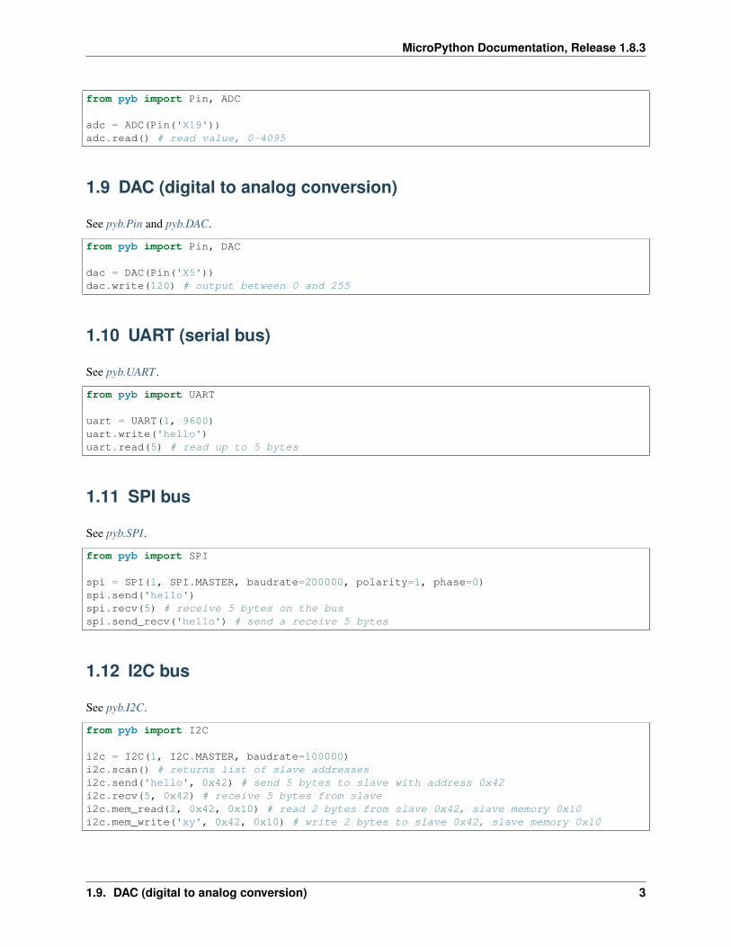
1.9 DAC (digital to analog conversion)
See pyb.Pin and pyb.DAC.
from pyb import Pin, DAC
dac = DAC(Pin('X5'))dac.write(120) # output between 0 and 255
1.10 UART (serial bus)
See pyb.UART .
from pyb import UART
uart = UART(1, 9600)uart.write('hello')uart.read(5) # read up to 5 bytes
1.11 SPI bus
See pyb.SPI.
from pyb import SPI
spi = SPI(1, SPI.MASTER, baudrate=200000, polarity=1, phase=0)spi.send('hello')spi.recv(5) # receive 5 bytes on the busspi.send_recv('hello') # send a receive 5 bytes
1.12 I2C bus
See pyb.I2C.
from pyb import I2C
i2c = I2C(1, I2C.MASTER, baudrate=100000)i2c.scan() # returns list of slave addressesi2c.send('hello', 0x42) # send 5 bytes to slave with address 0x42i2c.recv(5, 0x42) # receive 5 bytes from slavei2c.mem_read(2, 0x42, 0x10) # read 2 bytes from slave 0x42, slave memory 0x10i2c.mem_write('xy', 0x42, 0x10) # write 2 bytes to slave 0x42, slave memory 0x10
1.9. DAC (digital to analog conversion) 3
MicroPython Documentation, Release 1.8.3
4 Chapter 1. Quick reference for the pyboard
CHAPTER
TWO
GENERAL INFORMATION ABOUT THE PYBOARD
2.1 Local filesystem and SD card
There is a small internal filesystem (a drive) on the pyboard, called /flash, which is stored within the microcon-troller’s flash memory. If a micro SD card is inserted into the slot, it is available as /sd.
When the pyboard boots up, it needs to choose a filesystem to boot from. If there is no SD card, then it uses the internalfilesystem /flash as the boot filesystem, otherwise, it uses the SD card /sd.
(Note that on older versions of the board, /flash is called 0:/ and /sd is called 1:/).
The boot filesystem is used for 2 things: it is the filesystem from which the boot.py and main.py files are searchedfor, and it is the filesystem which is made available on your PC over the USB cable.
The filesystem will be available as a USB flash drive on your PC. You can save files to the drive, and edit boot.pyand main.py.
Remember to eject (on Linux, unmount) the USB drive before you reset your pyboard.
2.2 Boot modes
If you power up normally, or press the reset button, the pyboard will boot into standard mode: the boot.py file willbe executed first, then the USB will be configured, then main.py will run.
You can override this boot sequence by holding down the user switch as the board is booting up. Hold down userswitch and press reset, and then as you continue to hold the user switch, the LEDs will count in binary. When theLEDs have reached the mode you want, let go of the user switch, the LEDs for the selected mode will flash quickly,and the board will boot.
The modes are:
1. Green LED only, standard boot: run boot.py then main.py.
2. Orange LED only, safe boot: don’t run any scripts on boot-up.
3. Green and orange LED together, filesystem reset: resets the flash filesystem to its factory state, then boots insafe mode.
If your filesystem becomes corrupt, boot into mode 3 to fix it. If resetting the filesystem while plugged into yourcompute doesn’t work, you can try doing the same procedure while the board is plugged into a USB charger, or otherUSB power supply without data connection.
5
MicroPython Documentation, Release 1.8.3
2.3 Errors: flashing LEDs
There are currently 2 kinds of errors that you might see:
1. If the red and green LEDs flash alternatively, then a Python script (eg main.py) has an error. Use theREPL to debug it.
2. If all 4 LEDs cycle on and off slowly, then there was a hard fault. This cannot be recovered from and you needto do a hard reset.
6 Chapter 2. General information about the pyboard
CHAPTER
THREE
MICROPYTHON TUTORIAL
This tutorial is intended to get you started with your pyboard. All you need is a pyboard and a micro-USB cable toconnect it to your PC. If it is your first time, it is recommended to follow the tutorial through in the order below.
3.1 Introduction to the pyboard
To get the most out of your pyboard, there are a few basic things to understand about how it works.
3.1.1 Caring for your pyboard
Because the pyboard does not have a housing it needs a bit of care:
• Be gentle when plugging/unplugging the USB cable. Whilst the USB connector is soldered through the boardand is relatively strong, if it breaks off it can be very difficult to fix.
• Static electricity can shock the components on the pyboard and destroy them. If you experience a lot of staticelectricity in your area (eg dry and cold climates), take extra care not to shock the pyboard. If your pyboardcame in a black plastic box, then this box is the best way to store and carry the pyboard as it is an anti-static box(it is made of a conductive plastic, with conductive foam inside).
As long as you take care of the hardware, you should be okay. It’s almost impossible to break the software on thepyboard, so feel free to play around with writing code as much as you like. If the filesystem gets corrupt, see below onhow to reset it. In the worst case you might need to reflash the MicroPython software, but that can be done over USB.
3.1.2 Layout of the pyboard
The micro USB connector is on the top right, the micro SD card slot on the top left of the board. There are 4 LEDsbetween the SD slot and USB connector. The colours are: red on the bottom, then green, orange, and blue on the top.There are 2 switches: the right one is the reset switch, the left is the user switch.
3.1.3 Plugging in and powering on
The pyboard can be powered via USB. Connect it to your PC via a micro USB cable. There is only one way that thecable will fit. Once connected, the green LED on the board should flash quickly.
7

MicroPython Documentation, Release 1.8.3
3.1.4 Powering by an external power source
The pyboard can be powered by a battery or other external power source.
Be sure to connect the positive lead of the power supply to VIN, and ground to GND. There is no polarityprotection on the pyboard so you must be careful when connecting anything to VIN.
The input voltage must be between 3.6V and 10V.
3.2 Running your first script
Let’s jump right in and get a Python script running on the pyboard. After all, that’s what it’s all about!
3.2.1 Connecting your pyboard
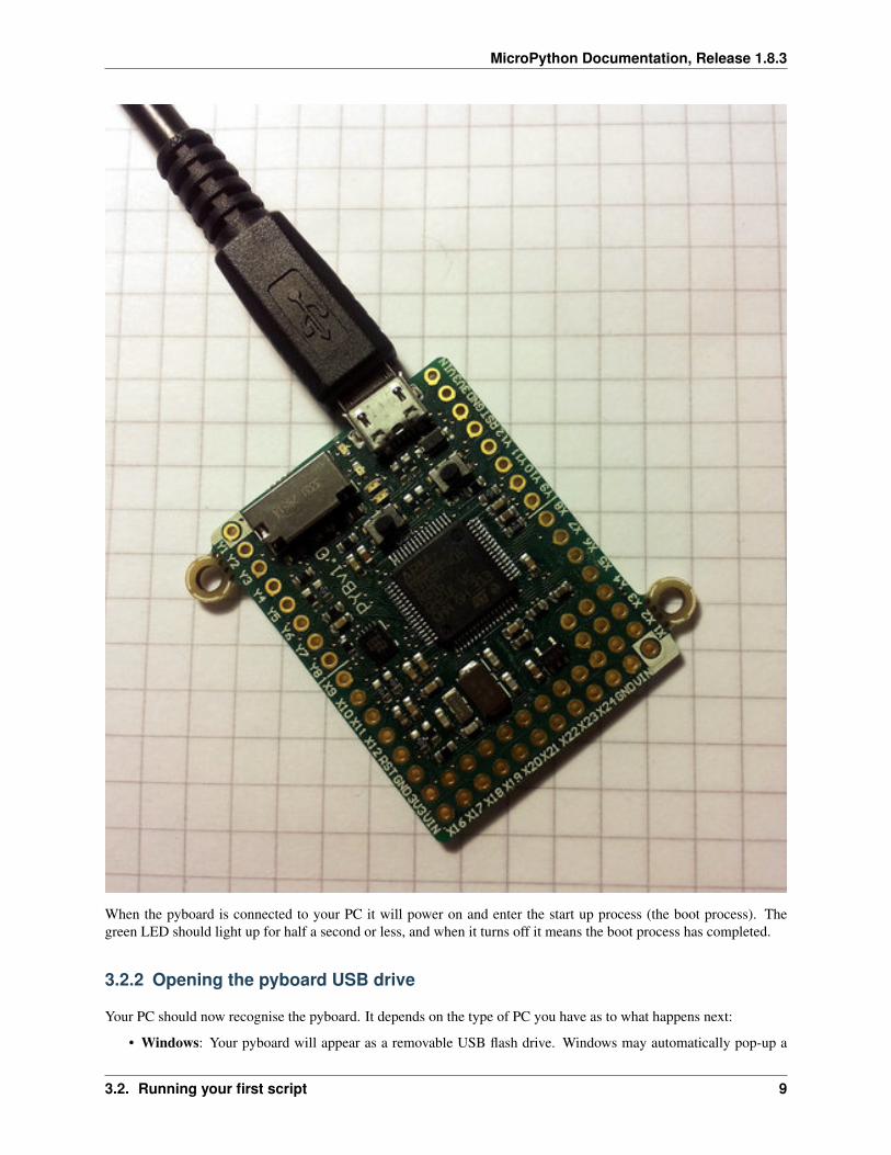
Connect your pyboard to your PC (Windows, Mac or Linux) with a micro USB cable. There is only one way that thecable will connect, so you can’t get it wrong.
8 Chapter 3. MicroPython tutorial
MicroPython Documentation, Release 1.8.3
When the pyboard is connected to your PC it will power on and enter the start up process (the boot process). Thegreen LED should light up for half a second or less, and when it turns off it means the boot process has completed.
3.2.2 Opening the pyboard USB drive
Your PC should now recognise the pyboard. It depends on the type of PC you have as to what happens next:
• Windows: Your pyboard will appear as a removable USB flash drive. Windows may automatically pop-up a
3.2. Running your first script 9
MicroPython Documentation, Release 1.8.3
window, or you may need to go there using Explorer.
Windows will also see that the pyboard has a serial device, and it will try to automatically configure this device.If it does, cancel the process. We will get the serial device working in the next tutorial.
• Mac: Your pyboard will appear on the desktop as a removable disc. It will probably be called “NONAME”.Click on it to open the pyboard folder.
• Linux: Your pyboard will appear as a removable medium. On Ubuntu it will mount automatically and pop-upa window with the pyboard folder. On other Linux distributions, the pyboard may be mounted automatically, oryou may need to do it manually. At a terminal command line, type lsblk to see a list of connected drives, andthen mount /dev/sdb1 (replace sdb1 with the appropriate device). You may need to be root to do this.
Okay, so you should now have the pyboard connected as a USB flash drive, and a window (or command line) shouldbe showing the files on the pyboard drive.
The drive you are looking at is known as /flash by the pyboard, and should contain the following 4 files:
• boot.py – this script is executed when the pyboard boots up. It sets up various configuration options for thepyboard.
• main.py – this is the main script that will contain your Python program. It is executed after boot.py.
• README.txt – this contains some very basic information about getting started with the pyboard.
• pybcdc.inf – this is a Windows driver file to configure the serial USB device. More about this in the nexttutorial.
3.2.3 Editing main.py
Now we are going to write our Python program, so open the main.py file in a text editor. On Windows you canuse notepad, or any other editor. On Mac and Linux, use your favourite text editor. With the file open you will see itcontains 1 line:
# main.py -- put your code here!
This line starts with a # character, which means that it is a comment. Such lines will not do anything, and are there foryou to write notes about your program.
Let’s add 2 lines to this main.py file, to make it look like this:
# main.py -- put your code here!import pybpyb.LED(4).on()
The first line we wrote says that we want to use the pyb module. This module contains all the functions and classesto control the features of the pyboard.
The second line that we wrote turns the blue LED on: it first gets the LED class from the pyb module, creates LEDnumber 4 (the blue LED), and then turns it on.
3.2.4 Resetting the pyboard
To run this little script, you need to first save and close the main.py file, and then eject (or unmount) the pyboardUSB drive. Do this like you would a normal USB flash drive.
When the drive is safely ejected/unmounted you can get to the fun part: press the RST switch on the pyboard to resetand run your script. The RST switch is the small black button just below the USB connector on the board, on the rightedge.
10 Chapter 3. MicroPython tutorial
MicroPython Documentation, Release 1.8.3
When you press RST the green LED will flash quickly, and then the blue LED should turn on and stay on.
Congratulations! You have written and run your very first MicroPython program!
3.3 Getting a MicroPython REPL prompt
REPL stands for Read Evaluate Print Loop, and is the name given to the interactive MicroPython prompt that you canaccess on the pyboard. Using the REPL is by far the easiest way to test out your code and run commands. You can usethe REPL in addition to writing scripts in main.py.
To use the REPL, you must connect to the serial USB device on the pyboard. How you do this depends on youroperating system.
3.3.1 Windows
You need to install the pyboard driver to use the serial USB device. The driver is on the pyboard’s USB flash drive,and is called pybcdc.inf.
To install this driver you need to go to Device Manager for your computer, find the pyboard in the list of devices (itshould have a warning sign next to it because it’s not working yet), right click on the pyboard device, select Properties,then Install Driver. You need to then select the option to find the driver manually (don’t use Windows auto update),navigate to the pyboard’s USB drive, and select that. It should then install. After installing, go back to the DeviceManager to find the installed pyboard, and see which COM port it is (eg COM4). More comprehensive instructions canbe found in the Guide for pyboard on Windows (PDF). Please consult this guide if you are having problems installingthe driver.
You now need to run your terminal program. You can use HyperTerminal if you have it installed, or download thefree program PuTTY: putty.exe. Using your serial program you must connect to the COM port that you found in theprevious step. With PuTTY, click on “Session” in the left-hand panel, then click the “Serial” radio button on the right,then enter you COM port (eg COM4) in the “Serial Line” box. Finally, click the “Open” button.
3.3.2 Mac OS X
Open a terminal and run:
screen /dev/tty.usbmodem*
When you are finished and want to exit screen, type CTRL-A CTRL-\.
3.3.3 Linux
Open a terminal and run:
screen /dev/ttyACM0
You can also try picocom or minicom instead of screen. You may have to use /dev/ttyACM1 or a higher numberfor ttyACM. And, you may need to give yourself the correct permissions to access this devices (eg group uucp ordialout, or use sudo).
3.3. Getting a MicroPython REPL prompt 11

MicroPython Documentation, Release 1.8.3
3.3.4 Using the REPL prompt
Now let’s try running some MicroPython code directly on the pyboard.
With your serial program open (PuTTY, screen, picocom, etc) you may see a blank screen with a flashing cursor. PressEnter and you should be presented with a MicroPython prompt, i.e. >>>. Let’s make sure it is working with theobligatory test:
>>> print("hello pyboard!")hello pyboard!
In the above, you should not type in the >>> characters. They are there to indicate that you should type the text afterit at the prompt. In the end, once you have entered the text print("hello pyboard!") and pressed Enter, theoutput on your screen should look like it does above.
If you already know some python you can now try some basic commands here.
If any of this is not working you can try either a hard reset or a soft reset; see below.
Go ahead and try typing in some other commands. For example:
>>> pyb.LED(1).on()>>> pyb.LED(2).on()>>> 1 + 23>>> 1 / 20.5>>> 20 * 'py''pypypypypypypypypypypypypypypypypypypypy'
3.3.5 Resetting the board
If something goes wrong, you can reset the board in two ways. The first is to press CTRL-D at the MicroPythonprompt, which performs a soft reset. You will see a message something like
>>>PYB: sync filesystemsPYB: soft rebootMicro Python v1.0 on 2014-05-03; PYBv1.0 with STM32F405RGType "help()" for more information.>>>
If that isn’t working you can perform a hard reset (turn-it-off-and-on-again) by pressing the RST switch (the smallblack button closest to the micro-USB socket on the board). This will end your session, disconnecting whateverprogram (PuTTY, screen, etc) that you used to connect to the pyboard.
If you are going to do a hard-reset, it’s recommended to first close your serial program and eject/unmount the pyboarddrive.
3.4 Turning on LEDs and basic Python concepts
The easiest thing to do on the pyboard is to turn on the LEDs attached to the board. Connect the board, and log in asdescribed in tutorial 1. We will start by turning and LED on in the interpreter, type the following
>>> myled = pyb.LED(1)>>> myled.on()>>> myled.off()
12 Chapter 3. MicroPython tutorial
MicroPython Documentation, Release 1.8.3
These commands turn the LED on and off.
This is all very well but we would like this process to be automated. Open the file MAIN.PY on the pyboard in yourfavourite text editor. Write or paste the following lines into the file. If you are new to python, then make sure you getthe indentation correct since this matters!
led = pyb.LED(2)while True:
led.toggle()pyb.delay(1000)
When you save, the red light on the pyboard should turn on for about a second. To run the script, do a soft reset(CTRL-D). The pyboard will then restart and you should see a green light continuously flashing on and off. Success,the first step on your path to building an army of evil robots! When you are bored of the annoying flashing light thenpress CTRL-C at your terminal to stop it running.
So what does this code do? First we need some terminology. Python is an object-oriented language, almost everythingin python is a class and when you create an instance of a class you get an object. Classes have methods associated tothem. A method (also called a member function) is used to interact with or control the object.
The first line of code creates an LED object which we have then called led. When we create the object, it takes a singleparameter which must be between 1 and 4, corresponding to the 4 LEDs on the board. The pyb.LED class has threeimportant member functions that we will use: on(), off() and toggle(). The other function that we use is pyb.delay()this simply waits for a given time in miliseconds. Once we have created the LED object, the statement while True:creates an infinite loop which toggles the led between on and off and waits for 1 second.
Exercise: Try changing the time between toggling the led and turning on a different LED.
Exercise: Connect to the pyboard directly, create a pyb.LED object and turn it on using the on() method.
3.4.1 A Disco on your pyboard
So far we have only used a single LED but the pyboard has 4 available. Let’s start by creating an object for each LEDso we can control each of them. We do that by creating a list of LEDS with a list comprehension.
leds = [pyb.LED(i) for i in range(1,5)]
If you call pyb.LED() with a number that isn’t 1,2,3,4 you will get an error message. Next we will set up an infiniteloop that cycles through each of the LEDs turning them on and off.
n = 0while True:
n = (n + 1) % 4leds[n].toggle()pyb.delay(50)
Here, n keeps track of the current LED and every time the loop is executed we cycle to the next n (the % sign is amodulus operator that keeps n between 0 and 3.) Then we access the nth LED and toggle it. If you run this you shouldsee each of the LEDs turning on then all turning off again in sequence.
One problem you might find is that if you stop the script and then start it again that the LEDs are stuck on fromthe previous run, ruining our carefully choreographed disco. We can fix this by turning all the LEDs off when weinitialise the script and then using a try/finally block. When you press CTRL-C, MicroPython generates a VCPInterruptexception. Exceptions normally mean something has gone wrong and you can use a try: command to “catch” anexception. In this case it is just the user interrupting the script, so we don’t need to catch the error but just tellMicroPython what to do when we exit. The finally block does this, and we use it to make sure all the LEDs are off.The full code is:
3.4. Turning on LEDs and basic Python concepts 13
MicroPython Documentation, Release 1.8.3
leds = [pyb.LED(i) for i in range(1,5)]for l in leds:
l.off()
n = 0try:
while True:n = (n + 1) % 4leds[n].toggle()pyb.delay(50)
finally:for l in leds:
l.off()
3.4.2 The Fourth Special LED
The blue LED is special. As well as turning it on and off, you can control the intensity using the intensity() method.This takes a number between 0 and 255 that determines how bright it is. The following script makes the blue LEDgradually brighter then turns it off again.
led = pyb.LED(4)intensity = 0while True:
intensity = (intensity + 1) % 255led.intensity(intensity)pyb.delay(20)
You can call intensity() on the other LEDs but they can only be off or on. 0 sets them off and any other number up to255 turns them on.
3.5 The Switch, callbacks and interrupts
The pyboard has 2 small switches, labelled USR and RST. The RST switch is a hard-reset switch, and if you press itthen it restarts the pyboard from scratch, equivalent to turning the power off then back on.
The USR switch is for general use, and is controlled via a Switch object. To make a switch object do:
>>> sw = pyb.Switch()
Remember that you may need to type import pyb if you get an error that the name pyb does not exist.
With the switch object you can get its status:
>>> sw()False
This will print False if the switch is not held, or True if it is held. Try holding the USR switch down while runningthe above command.
3.5.1 Switch callbacks
The switch is a very simple object, but it does have one advanced feature: the sw.callback() function. Thecallback function sets up something to run when the switch is pressed, and uses an interrupt. It’s probably best to startwith an example before understanding how interrupts work. Try running the following at the prompt:
14 Chapter 3. MicroPython tutorial
MicroPython Documentation, Release 1.8.3
>>> sw.callback(lambda:print('press!'))
This tells the switch to print press! each time the switch is pressed down. Go ahead and try it: press the USR switchand watch the output on your PC. Note that this print will interrupt anything you are typing, and is an example of aninterrupt routine running asynchronously.
As another example try:
>>> sw.callback(lambda:pyb.LED(1).toggle())
This will toggle the red LED each time the switch is pressed. And it will even work while other code is running.
To disable the switch callback, pass None to the callback function:
>>> sw.callback(None)
You can pass any function (that takes zero arguments) to the switch callback. Above we used the lambda feature ofPython to create an anonymous function on the fly. But we could equally do:
>>> def f():... pyb.LED(1).toggle()...>>> sw.callback(f)
This creates a function called f and assigns it to the switch callback. You can do things this way when your functionis more complicated than a lambda will allow.
Note that your callback functions must not allocate any memory (for example they cannot create a tuple or list).Callback functions should be relatively simple. If you need to make a list, make it beforehand and store it in a globalvariable (or make it local and close over it). If you need to do a long, complicated calculation, then use the callback toset a flag which some other code then responds to.
3.5.2 Technical details of interrupts
Let’s step through the details of what is happening with the switch callback. When you register a function withsw.callback(), the switch sets up an external interrupt trigger (falling edge) on the pin that the switch is connectedto. This means that the microcontroller will listen on the pin for any changes, and the following will occur:
1. When the switch is pressed a change occurs on the pin (the pin goes from low to high), and the microcontrollerregisters this change.
2. The microcontroller finishes executing the current machine instruction, stops execution, and saves its currentstate (pushes the registers on the stack). This has the effect of pausing any code, for example your runningPython script.
3. The microcontroller starts executing the special interrupt handler associated with the switch’s external trigger.This interrupt handler get the function that you registered with sw.callback() and executes it.
4. Your callback function is executed until it finishes, returning control to the switch interrupt handler.
5. The switch interrupt handler returns, and the microcontroller is notified that the interrupt has been dealt with.
6. The microcontroller restores the state that it saved in step 2.
7. Execution continues of the code that was running at the beginning. Apart from the pause, this code does notnotice that it was interrupted.
The above sequence of events gets a bit more complicated when multiple interrupts occur at the same time. In thatcase, the interrupt with the highest priority goes first, then the others in order of their priority. The switch interrupt isset at the lowest priority.
3.5. The Switch, callbacks and interrupts 15
MicroPython Documentation, Release 1.8.3
3.5.3 Further reading
For further information about using hardware interrupts see writing interrupt handlers.
3.6 The accelerometer
Here you will learn how to read the accelerometer and signal using LEDs states like tilt left and tilt right.
3.6.1 Using the accelerometer
The pyboard has an accelerometer (a tiny mass on a tiny spring) that can be used to detect the angle of the board andmotion. There is a different sensor for each of the x, y, z directions. To get the value of the accelerometer, create apyb.Accel() object and then call the x() method.
>>> accel = pyb.Accel()>>> accel.x()7
This returns a signed integer with a value between around -30 and 30. Note that the measurement is very noisy, thismeans that even if you keep the board perfectly still there will be some variation in the number that you measure.Because of this, you shouldn’t use the exact value of the x() method but see if it is in a certain range.
We will start by using the accelerometer to turn on a light if it is not flat.
accel = pyb.Accel()light = pyb.LED(3)SENSITIVITY = 3
while True:x = accel.x()if abs(x) > SENSITIVITY:
light.on()else:
light.off()
pyb.delay(100)
We create Accel and LED objects, then get the value of the x direction of the accelerometer. If the magnitude of xis bigger than a certain value SENSITIVITY, then the LED turns on, otherwise it turns off. The loop has a smallpyb.delay() otherwise the LED flashes annoyingly when the value of x is close to SENSITIVITY. Try runningthis on the pyboard and tilt the board left and right to make the LED turn on and off.
Exercise: Change the above script so that the blue LED gets brighter the more you tilt the pyboard. HINT: Youwill need to rescale the values, intensity goes from 0-255.
3.6.2 Making a spirit level
The example above is only sensitive to the angle in the x direction but if we use the y() value and more LEDs we canturn the pyboard into a spirit level.
xlights = (pyb.LED(2), pyb.LED(3))ylights = (pyb.LED(1), pyb.LED(4))
accel = pyb.Accel()
16 Chapter 3. MicroPython tutorial
MicroPython Documentation, Release 1.8.3
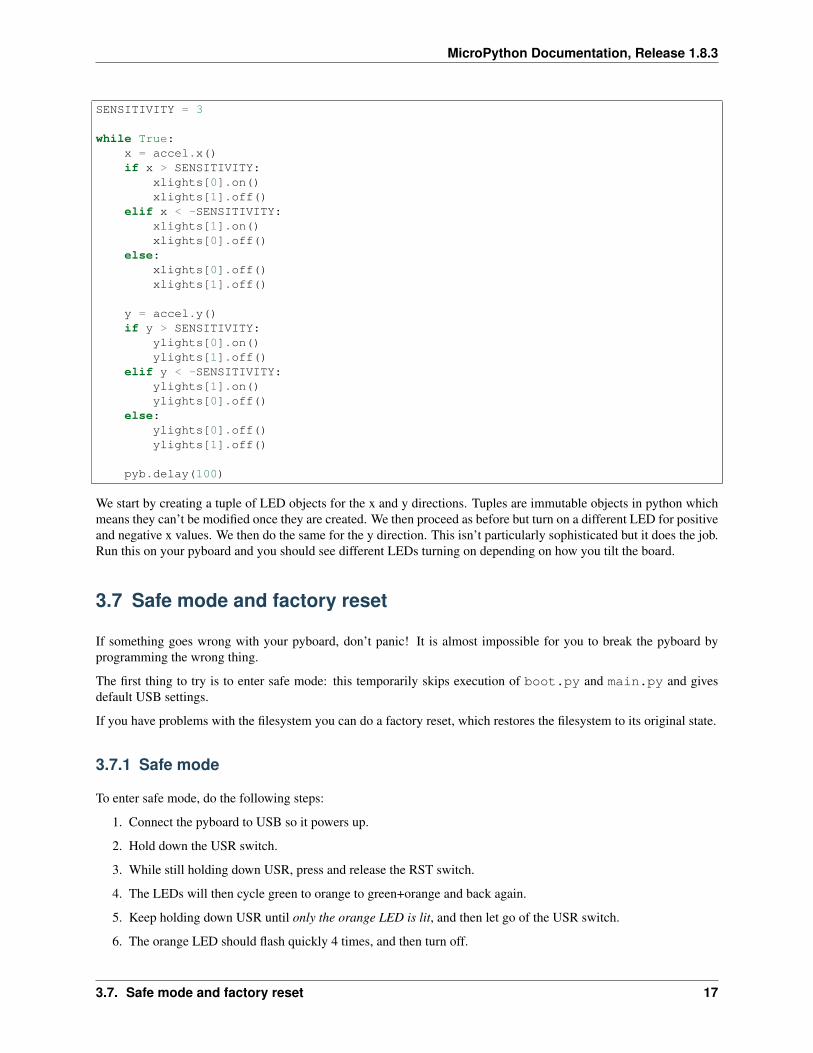
SENSITIVITY = 3
while True:x = accel.x()if x > SENSITIVITY:
xlights[0].on()xlights[1].off()
elif x < -SENSITIVITY:xlights[1].on()xlights[0].off()
else:xlights[0].off()xlights[1].off()
y = accel.y()if y > SENSITIVITY:
ylights[0].on()ylights[1].off()
elif y < -SENSITIVITY:ylights[1].on()ylights[0].off()
else:ylights[0].off()ylights[1].off()
pyb.delay(100)
We start by creating a tuple of LED objects for the x and y directions. Tuples are immutable objects in python whichmeans they can’t be modified once they are created. We then proceed as before but turn on a different LED for positiveand negative x values. We then do the same for the y direction. This isn’t particularly sophisticated but it does the job.Run this on your pyboard and you should see different LEDs turning on depending on how you tilt the board.
3.7 Safe mode and factory reset
If something goes wrong with your pyboard, don’t panic! It is almost impossible for you to break the pyboard byprogramming the wrong thing.
The first thing to try is to enter safe mode: this temporarily skips execution of boot.py and main.py and givesdefault USB settings.
If you have problems with the filesystem you can do a factory reset, which restores the filesystem to its original state.
3.7.1 Safe mode
To enter safe mode, do the following steps:
1. Connect the pyboard to USB so it powers up.
2. Hold down the USR switch.
3. While still holding down USR, press and release the RST switch.
4. The LEDs will then cycle green to orange to green+orange and back again.
5. Keep holding down USR until only the orange LED is lit, and then let go of the USR switch.
6. The orange LED should flash quickly 4 times, and then turn off.
3.7. Safe mode and factory reset 17
MicroPython Documentation, Release 1.8.3
7. You are now in safe mode.
In safe mode, the boot.py and main.py files are not executed, and so the pyboard boots up with default settings.This means you now have access to the filesystem (the USB drive should appear), and you can edit boot.py andmain.py to fix any problems.
Entering safe mode is temporary, and does not make any changes to the files on the pyboard.
3.7.2 Factory reset the filesystem
If you pyboard’s filesystem gets corrupted (for example, you forgot to eject/unmount it), or you have some code inboot.py or main.py which you can’t escape from, then you can reset the filesystem.
Resetting the filesystem deletes all files on the internal pyboard storage (not the SD card), and restores the filesboot.py, main.py, README.txt and pybcdc.inf back to their original state.
To do a factory reset of the filesystem you follow a similar procedure as you did to enter safe mode, but release USRon green+orange:
1. Connect the pyboard to USB so it powers up.
2. Hold down the USR switch.
3. While still holding down USR, press and release the RST switch.
4. The LEDs will then cycle green to orange to green+orange and back again.
5. Keep holding down USR until both the green and orange LEDs are lit, and then let go of the USR switch.
6. The green and orange LEDs should flash quickly 4 times.
7. The red LED will turn on (so red, green and orange are now on).
8. The pyboard is now resetting the filesystem (this takes a few seconds).
9. The LEDs all turn off.
10. You now have a reset filesystem, and are in safe mode.
11. Press and release the RST switch to boot normally.
3.8 Making the pyboard act as a USB mouse
The pyboard is a USB device, and can configured to act as a mouse instead of the default USB flash drive.
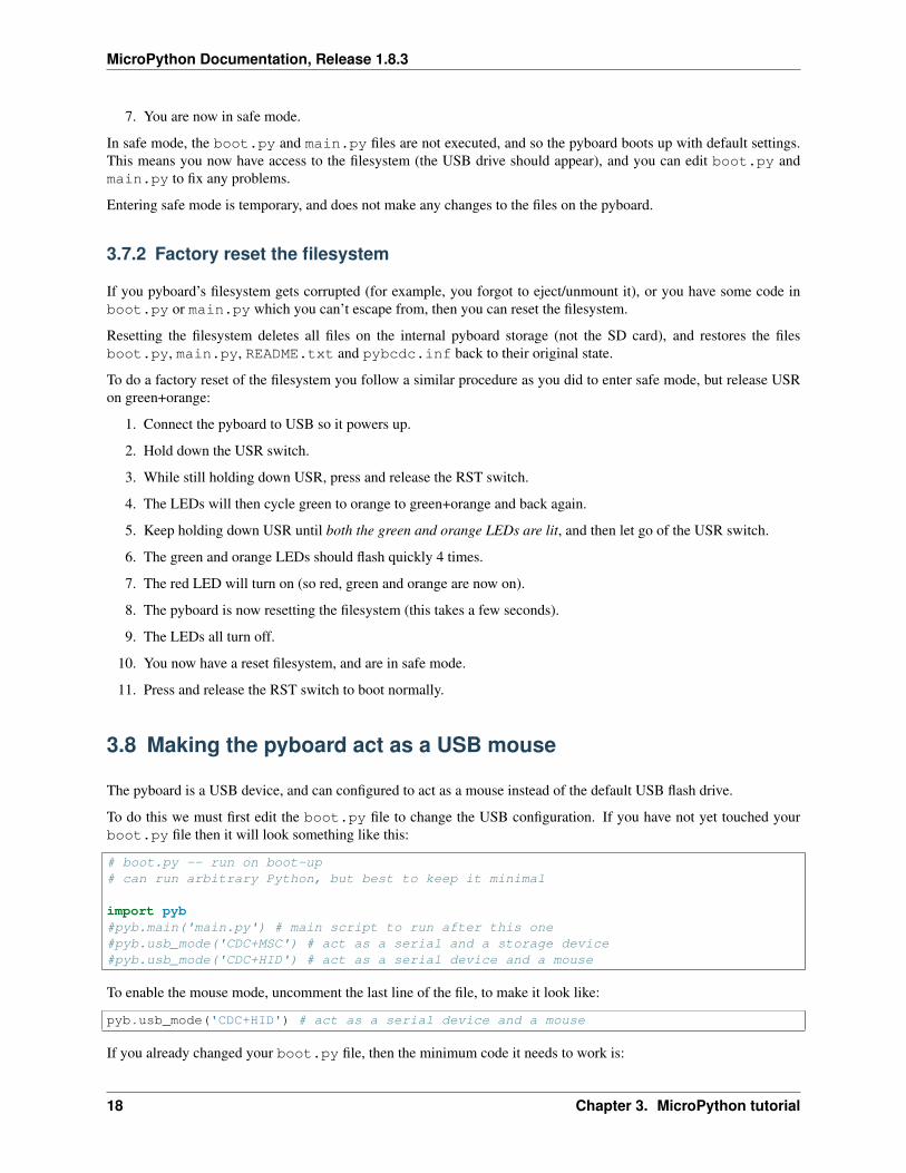
To do this we must first edit the boot.py file to change the USB configuration. If you have not yet touched yourboot.py file then it will look something like this:
# boot.py -- run on boot-up# can run arbitrary Python, but best to keep it minimal
import pyb#pyb.main('main.py') # main script to run after this one#pyb.usb_mode('CDC+MSC') # act as a serial and a storage device#pyb.usb_mode('CDC+HID') # act as a serial device and a mouse
To enable the mouse mode, uncomment the last line of the file, to make it look like:
pyb.usb_mode('CDC+HID') # act as a serial device and a mouse
If you already changed your boot.py file, then the minimum code it needs to work is:
18 Chapter 3. MicroPython tutorial
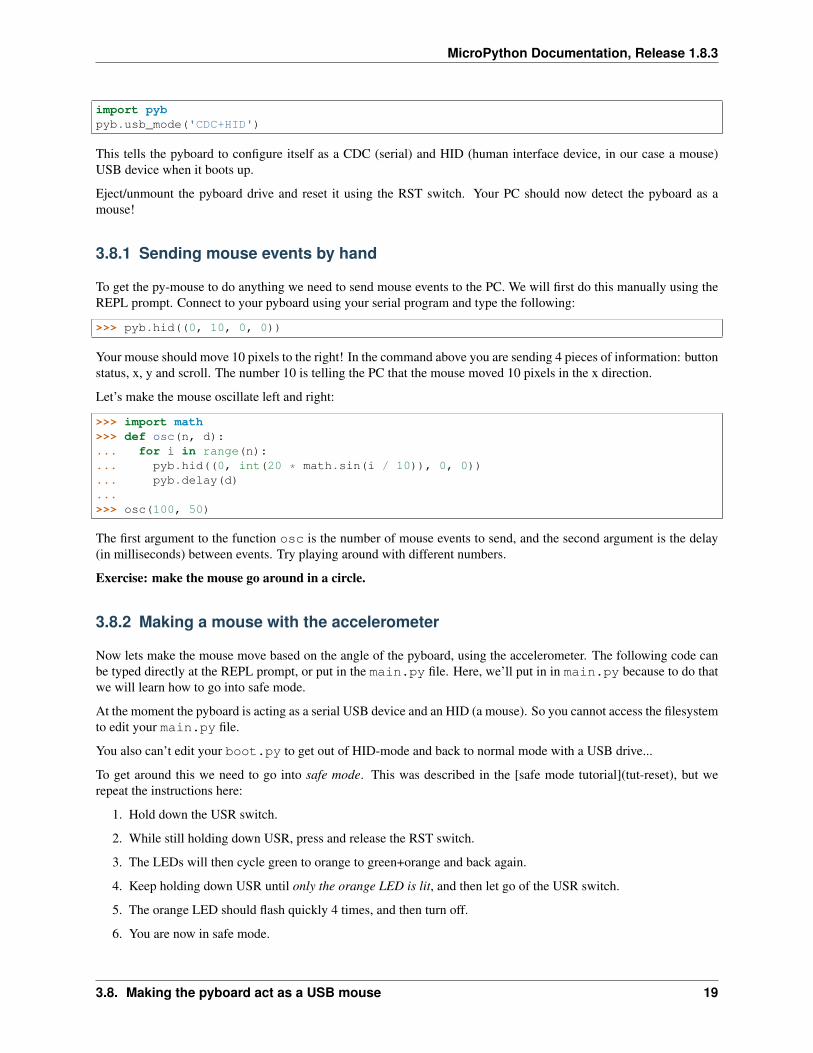
MicroPython Documentation, Release 1.8.3
import pybpyb.usb_mode('CDC+HID')
This tells the pyboard to configure itself as a CDC (serial) and HID (human interface device, in our case a mouse)USB device when it boots up.
Eject/unmount the pyboard drive and reset it using the RST switch. Your PC should now detect the pyboard as amouse!
3.8.1 Sending mouse events by hand
To get the py-mouse to do anything we need to send mouse events to the PC. We will first do this manually using theREPL prompt. Connect to your pyboard using your serial program and type the following:
>>> pyb.hid((0, 10, 0, 0))
Your mouse should move 10 pixels to the right! In the command above you are sending 4 pieces of information: buttonstatus, x, y and scroll. The number 10 is telling the PC that the mouse moved 10 pixels in the x direction.
Let’s make the mouse oscillate left and right:
>>> import math>>> def osc(n, d):... for i in range(n):... pyb.hid((0, int(20 * math.sin(i / 10)), 0, 0))... pyb.delay(d)...>>> osc(100, 50)
The first argument to the function osc is the number of mouse events to send, and the second argument is the delay(in milliseconds) between events. Try playing around with different numbers.
Exercise: make the mouse go around in a circle.
3.8.2 Making a mouse with the accelerometer
Now lets make the mouse move based on the angle of the pyboard, using the accelerometer. The following code canbe typed directly at the REPL prompt, or put in the main.py file. Here, we’ll put in in main.py because to do thatwe will learn how to go into safe mode.
At the moment the pyboard is acting as a serial USB device and an HID (a mouse). So you cannot access the filesystemto edit your main.py file.
You also can’t edit your boot.py to get out of HID-mode and back to normal mode with a USB drive...
To get around this we need to go into safe mode. This was described in the [safe mode tutorial](tut-reset), but werepeat the instructions here:
1. Hold down the USR switch.
2. While still holding down USR, press and release the RST switch.
3. The LEDs will then cycle green to orange to green+orange and back again.
4. Keep holding down USR until only the orange LED is lit, and then let go of the USR switch.
5. The orange LED should flash quickly 4 times, and then turn off.
6. You are now in safe mode.
3.8. Making the pyboard act as a USB mouse 19
MicroPython Documentation, Release 1.8.3
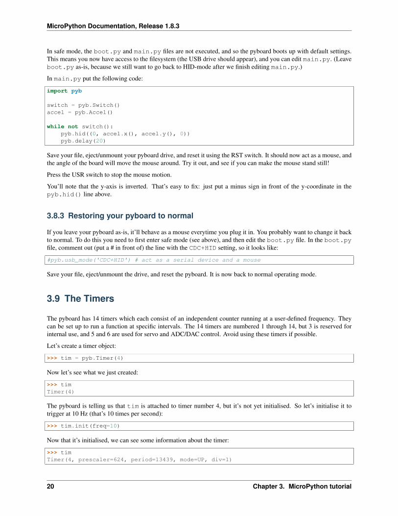
In safe mode, the boot.py and main.py files are not executed, and so the pyboard boots up with default settings.This means you now have access to the filesystem (the USB drive should appear), and you can edit main.py. (Leaveboot.py as-is, because we still want to go back to HID-mode after we finish editing main.py.)
In main.py put the following code:
import pyb
switch = pyb.Switch()accel = pyb.Accel()
while not switch():pyb.hid((0, accel.x(), accel.y(), 0))pyb.delay(20)
Save your file, eject/unmount your pyboard drive, and reset it using the RST switch. It should now act as a mouse, andthe angle of the board will move the mouse around. Try it out, and see if you can make the mouse stand still!
Press the USR switch to stop the mouse motion.
You’ll note that the y-axis is inverted. That’s easy to fix: just put a minus sign in front of the y-coordinate in thepyb.hid() line above.
3.8.3 Restoring your pyboard to normal
If you leave your pyboard as-is, it’ll behave as a mouse everytime you plug it in. You probably want to change it backto normal. To do this you need to first enter safe mode (see above), and then edit the boot.py file. In the boot.pyfile, comment out (put a # in front of) the line with the CDC+HID setting, so it looks like:
#pyb.usb_mode('CDC+HID') # act as a serial device and a mouse
Save your file, eject/unmount the drive, and reset the pyboard. It is now back to normal operating mode.
3.9 The Timers
The pyboard has 14 timers which each consist of an independent counter running at a user-defined frequency. Theycan be set up to run a function at specific intervals. The 14 timers are numbered 1 through 14, but 3 is reserved forinternal use, and 5 and 6 are used for servo and ADC/DAC control. Avoid using these timers if possible.
Let’s create a timer object:
>>> tim = pyb.Timer(4)
Now let’s see what we just created:
>>> timTimer(4)
The pyboard is telling us that tim is attached to timer number 4, but it’s not yet initialised. So let’s initialise it totrigger at 10 Hz (that’s 10 times per second):
>>> tim.init(freq=10)
Now that it’s initialised, we can see some information about the timer:
>>> timTimer(4, prescaler=624, period=13439, mode=UP, div=1)
20 Chapter 3. MicroPython tutorial
MicroPython Documentation, Release 1.8.3
The information means that this timer is set to run at the peripheral clock speed divided by 624+1, and it will countfrom 0 up to 13439, at which point it triggers an interrupt, and then starts counting again from 0. These num-bers are set to make the timer trigger at 10 Hz: the source frequency of the timer is 84MHz (found by runningtim.source_freq()) so we get 84MHz / 625 / 13440 = 10Hz.
3.9.1 Timer counter
So what can we do with our timer? The most basic thing is to get the current value of its counter:
>>> tim.counter()21504
This counter will continuously change, and counts up.
3.9.2 Timer callbacks
The next thing we can do is register a callback function for the timer to execute when it triggers (see the [switchtutorial](tut-switch) for an introduction to callback functions):
>>> tim.callback(lambda t:pyb.LED(1).toggle())
This should start the red LED flashing right away. It will be flashing at 5 Hz (2 toggle’s are needed for 1 flash, sotoggling at 10 Hz makes it flash at 5 Hz). You can change the frequency by re-initialising the timer:
>>> tim.init(freq=20)
You can disable the callback by passing it the value None:
>>> tim.callback(None)
The function that you pass to callback must take 1 argument, which is the timer object that triggered. This allows youto control the timer from within the callback function.
We can create 2 timers and run them independently:
>>> tim4 = pyb.Timer(4, freq=10)>>> tim7 = pyb.Timer(7, freq=20)>>> tim4.callback(lambda t: pyb.LED(1).toggle())>>> tim7.callback(lambda t: pyb.LED(2).toggle())
Because the callbacks are proper hardware interrupts, we can continue to use the pyboard for other things while thesetimers are running.
3.9.3 Making a microsecond counter
You can use a timer to create a microsecond counter, which might be useful when you are doing something whichrequires accurate timing. We will use timer 2 for this, since timer 2 has a 32-bit counter (so does timer 5, but if youuse timer 5 then you can’t use the Servo driver at the same time).
We set up timer 2 as follows:
>>> micros = pyb.Timer(2, prescaler=83, period=0x3fffffff)
The prescaler is set at 83, which makes this timer count at 1 MHz. This is because the CPU clock, running at 168MHz, is divided by 2 and then by prescaler+1, giving a frequency of 168 MHz/2/(83+1)=1 MHz for timer 2. Theperiod is set to a large number so that the timer can count up to a large number before wrapping back around to zero.In this case it will take about 17 minutes before it cycles back to zero.
3.9. The Timers 21
MicroPython Documentation, Release 1.8.3
To use this timer, it’s best to first reset it to 0:
>>> micros.counter(0)
and then perform your timing:
>>> start_micros = micros.counter()
... do some stuff ...
>>> end_micros = micros.counter()
3.10 Inline assembler
Here you will learn how to write inline assembler in MicroPython.
Note: this is an advanced tutorial, intended for those who already know a bit about microcontrollers and assemblylanguage.
MicroPython includes an inline assembler. It allows you to write assembly routines as a Python function, and you cancall them as you would a normal Python function.
3.10.1 Returning a value
Inline assembler functions are denoted by a special function decorator. Let’s start with the simplest example:
@micropython.asm_thumbdef fun():
movw(r0, 42)
You can enter this in a script or at the REPL. This function takes no arguments and returns the number 42. r0 isa register, and the value in this register when the function returns is the value that is returned. MicroPython alwaysinterprets the r0 as an integer, and converts it to an integer object for the caller.
If you run print(fun()) you will see it print out 42.
3.10.2 Accessing peripherals
For something a bit more complicated, let’s turn on an LED:
@micropython.asm_thumbdef led_on():
movwt(r0, stm.GPIOA)movw(r1, 1 << 13)strh(r1, [r0, stm.GPIO_BSRRL])
This code uses a few new concepts:
• stm is a module which provides a set of constants for easy access to the registers of the pyboard’s microcon-troller. Try running import stm and then help(stm) at the REPL. It will give you a list of all the availableconstants.
• stm.GPIOA is the address in memory of the GPIOA peripheral. On the pyboard, the red LED is on port A, pinPA13.
• movwt moves a 32-bit number into a register. It is a convenience function that turns into 2 thumb instructions:movw followed by movt. The movt also shifts the immediate value right by 16 bits.
22 Chapter 3. MicroPython tutorial
MicroPython Documentation, Release 1.8.3
• strh stores a half-word (16 bits). The instruction above stores the lower 16-bits of r1 into the memorylocation r0 + stm.GPIO_BSRRL. This has the effect of setting high all those pins on port A for which thecorresponding bit in r0 is set. In our example above, the 13th bit in r0 is set, so PA13 is pulled high. This turnson the red LED.
3.10.3 Accepting arguments
Inline assembler functions can accept up to 4 arguments. If they are used, they must be named r0, r1, r2 and r3 toreflect the registers and the calling conventions.
Here is a function that adds its arguments:
@micropython.asm_thumbdef asm_add(r0, r1):
add(r0, r0, r1)
This performs the computation r0 = r0 + r1. Since the result is put in r0, that is what is returned. Tryasm_add(1, 2), it should return 3.
3.10.4 Loops
We can assign labels with label(my_label), and branch to them using b(my_label), or a conditional branchlike bgt(my_label).
The following example flashes the green LED. It flashes it r0 times.
@micropython.asm_thumbdef flash_led(r0):
# get the GPIOA address in r1movwt(r1, stm.GPIOA)
# get the bit mask for PA14 (the pin LED #2 is on)movw(r2, 1 << 14)
b(loop_entry)
label(loop1)
# turn LED onstrh(r2, [r1, stm.GPIO_BSRRL])
# delay for a bitmovwt(r4, 5599900)label(delay_on)sub(r4, r4, 1)cmp(r4, 0)bgt(delay_on)
# turn LED offstrh(r2, [r1, stm.GPIO_BSRRH])
# delay for a bitmovwt(r4, 5599900)label(delay_off)sub(r4, r4, 1)cmp(r4, 0)bgt(delay_off)
3.10. Inline assembler 23
MicroPython Documentation, Release 1.8.3
# loop r0 timessub(r0, r0, 1)label(loop_entry)cmp(r0, 0)bgt(loop1)
3.10.5 Further reading
For further information about supported instructions of the inline assembler, see the reference documentation.
3.11 Power control
pyb.wfi() is used to reduce power consumption while waiting for an event such as an interrupt. You would use itin the following situation:
while True:do_some_processing()pyb.wfi()
Control the frequency using pyb.freq():
pyb.freq(30000000) # set CPU frequency to 30MHz
3.12 Tutorials requiring extra components
3.12.1 Controlling hobby servo motors
There are 4 dedicated connection points on the pyboard for connecting up hobby servo motors (see eg[Wikipedia](http://en.wikipedia.org/wiki/Servo_%28radio_control%29)). These motors have 3 wires: ground, powerand signal. On the pyboard you can connect them in the bottom right corner, with the signal pin on the far right. PinsX1, X2, X3 and X4 are the 4 dedicated servo signal pins.
24 Chapter 3. MicroPython tutorial

MicroPython Documentation, Release 1.8.3
In this picture there are male-male double adaptors to connect the servos to the header pins on the pyboard.
The ground wire on a servo is usually the darkest coloured one, either black or dark brown. The power wire will mostlikely be red.
The power pin for the servos (labelled VIN) is connected directly to the input power source of the pyboard. Whenpowered via USB, VIN is powered through a diode by the 5V USB power line. Connect to USB, the pyboard canpower at least 4 small to medium sized servo motors.
3.12. Tutorials requiring extra components 25
MicroPython Documentation, Release 1.8.3
If using a battery to power the pyboard and run servo motors, make sure it is not greater than 6V, since this is themaximum voltage most servo motors can take. (Some motors take only up to 4.8V, so check what type you are using.)
Creating a Servo object
Plug in a servo to position 1 (the one with pin X1) and create a servo object using:
>>> servo1 = pyb.Servo(1)
To change the angle of the servo use the angle method:
>>> servo1.angle(45)>>> servo1.angle(-60)
The angle here is measured in degrees, and ranges from about -90 to +90, depending on the motor. Calling anglewithout parameters will return the current angle:
>>> servo1.angle()-60
Note that for some angles, the returned angle is not exactly the same as the angle you set, due to rounding errors insetting the pulse width.
You can pass a second parameter to the angle method, which specifies how long to take (in milliseconds) to reachthe desired angle. For example, to take 1 second (1000 milliseconds) to go from the current position to 50 degrees, use
>>> servo1.angle(50, 1000)
This command will return straight away and the servo will continue to move to the desired angle, and stop when itgets there. You can use this feature as a speed control, or to synchronise 2 or more servo motors. If we have anotherservo motor (servo2 = pyb.Servo(2)) then we can do
>>> servo1.angle(-45, 2000); servo2.angle(60, 2000)
This will move the servos together, making them both take 2 seconds to reach their final angles.
Note: the semicolon between the 2 expressions above is used so that they are executed one after the other when youpress enter at the REPL prompt. In a script you don’t need to do this, you can just write them one line after the other.
Continuous rotation servos
So far we have been using standard servos that move to a specific angle and stay at that angle. These servo motorsare useful to create joints of a robot, or things like pan-tilt mechanisms. Internally, the motor has a variable resistor(potentiometer) which measures the current angle and applies power to the motor proportional to how far it is from thedesired angle. The desired angle is set by the width of a high-pulse on the servo signal wire. A pulse width of 1500microsecond corresponds to the centre position (0 degrees). The pulses are sent at 50 Hz, ie 50 pulses per second.
You can also get continuous rotation servo motors which turn continuously clockwise or counterclockwise. Thedirection and speed of rotation is set by the pulse width on the signal wire. A pulse width of 1500 microsecondscorresponds to a stopped motor. A pulse width smaller or larger than this means rotate one way or the other, at a givenspeed.
On the pyboard, the servo object for a continuous rotation motor is the same as before. In fact, using angle you canset the speed. But to make it easier to understand what is intended, there is another method called speed which setsthe speed:
>>> servo1.speed(30)
26 Chapter 3. MicroPython tutorial
MicroPython Documentation, Release 1.8.3
speed has the same functionality as angle: you can get the speed, set it, and set it with a time to reach the finalspeed.
>>> servo1.speed()30>>> servo1.speed(-20)>>> servo1.speed(0, 2000)
The final command above will set the motor to stop, but take 2 seconds to do it. This is essentially a control over theacceleration of the continuous servo.
A servo speed of 100 (or -100) is considered maximum speed, but actually you can go a bit faster than that, dependingon the particular motor.
The only difference between the angle and speed methods (apart from the name) is the way the input numbers(angle or speed) are converted to a pulse width.
Calibration
The conversion from angle or speed to pulse width is done by the servo object using its calibration values. To get thecurrent calibration, use
>>> servo1.calibration()(640, 2420, 1500, 2470, 2200)
There are 5 numbers here, which have meaning:
1. Minimum pulse width; the smallest pulse width that the servo accepts.
2. Maximum pulse width; the largest pulse width that the servo accepts.
3. Centre pulse width; the pulse width that puts the servo at 0 degrees or 0 speed.
4. The pulse width corresponding to 90 degrees. This sets the conversion in the method angle of angle to pulsewidth.
5. The pulse width corresponding to a speed of 100. This sets the conversion in the method speed of speed topulse width.
You can recalibrate the servo (change its default values) by using:
>>> servo1.calibration(700, 2400, 1510, 2500, 2000)
Of course, you would change the above values to suit your particular servo motor.
3.12.2 Fading LEDs
In addition to turning LEDs on and off, it is also possible to control the brightness of an LED using Pulse-WidthModulation (PWM), a common technique for obtaining variable output from a digital pin. This allows us to fade anLED:
Components
You will need:
• Standard 5 or 3 mm LED
• 100 Ohm resistor
3.12. Tutorials requiring extra components 27
MicroPython Documentation, Release 1.8.3
• Wires
• Breadboard (optional, but makes things easier)
Connecting Things Up
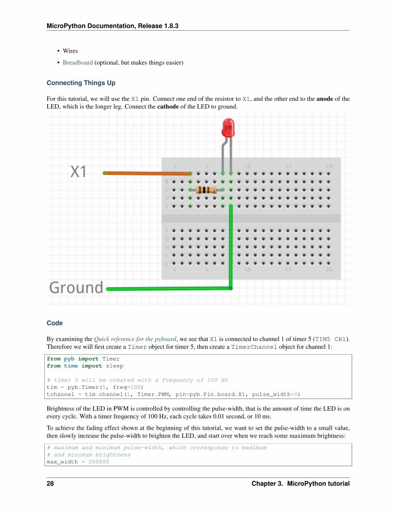
For this tutorial, we will use the X1 pin. Connect one end of the resistor to X1, and the other end to the anode of theLED, which is the longer leg. Connect the cathode of the LED to ground.
Code
By examining the Quick reference for the pyboard, we see that X1 is connected to channel 1 of timer 5 (TIM5 CH1).Therefore we will first create a Timer object for timer 5, then create a TimerChannel object for channel 1:
from pyb import Timerfrom time import sleep
# timer 5 will be created with a frequency of 100 Hztim = pyb.Timer(5, freq=100)tchannel = tim.channel(1, Timer.PWM, pin=pyb.Pin.board.X1, pulse_width=0)
Brightness of the LED in PWM is controlled by controlling the pulse-width, that is the amount of time the LED is onevery cycle. With a timer frequency of 100 Hz, each cycle takes 0.01 second, or 10 ms.
To achieve the fading effect shown at the beginning of this tutorial, we want to set the pulse-width to a small value,then slowly increase the pulse-width to brighten the LED, and start over when we reach some maximum brightness:
# maximum and minimum pulse-width, which corresponds to maximum# and minimum brightnessmax_width = 200000
28 Chapter 3. MicroPython tutorial
MicroPython Documentation, Release 1.8.3
min_width = 20000
# how much to change the pulse-width by each stepwstep = 1500cur_width = min_width
while True:tchannel.pulse_width(cur_width)
# this determines how often we change the pulse-width. It is# analogous to frames-per-secondsleep(0.01)
cur_width += wstep
if cur_width > max_width:cur_width = min_width
Breathing Effect
If we want to have a breathing effect, where the LED fades from dim to bright then bright to dim, then we simply needto reverse the sign of wstep when we reach maximum brightness, and reverse it again at minimum brightness. To dothis we modify the while loop to be:
while True:tchannel.pulse_width(cur_width)
sleep(0.01)
cur_width += wstep
if cur_width > max_width:cur_width = max_widthwstep *= -1
elif cur_width < min_width:cur_width = min_widthwstep *= -1
Advanced Exercise
You may have noticed that the LED brightness seems to fade slowly, but increases quickly. This is because our eyesinterprets brightness logarithmically (Weber’s Law ), while the LED’s brightness changes linearly, that is by the sameamount each time. How do you solve this problem? (Hint: what is the opposite of the logarithmic function?)
Addendum
We could have also used the digital-to-analog converter (DAC) to achieve the same effect. The PWM method has theadvantage that it drives the LED with the same current each time, but for different lengths of time. This allows bettercontrol over the brightness, because LEDs do not necessarily exhibit a linear relationship between the driving currentand brightness.
3.12. Tutorials requiring extra components 29
MicroPython Documentation, Release 1.8.3
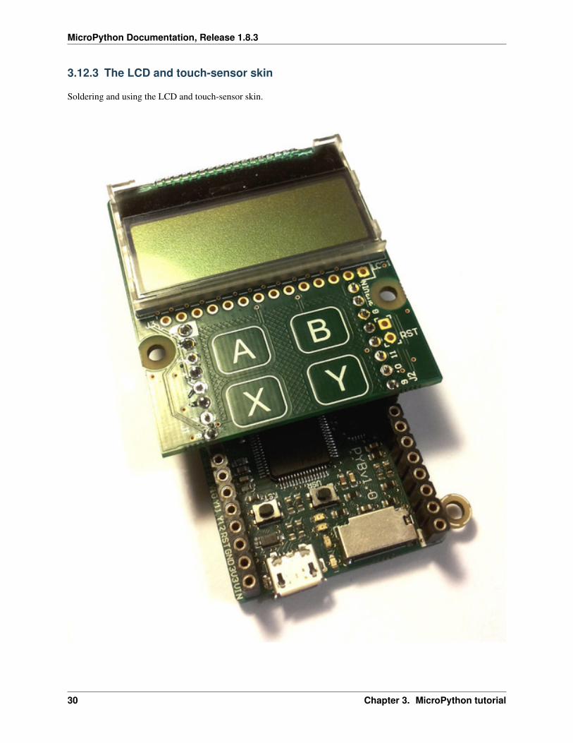
3.12.3 The LCD and touch-sensor skin
Soldering and using the LCD and touch-sensor skin.
30 Chapter 3. MicroPython tutorial
MicroPython Documentation, Release 1.8.3
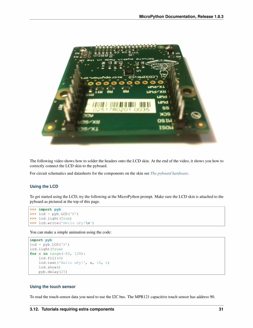
The following video shows how to solder the headers onto the LCD skin. At the end of the video, it shows you how tocorrectly connect the LCD skin to the pyboard.
For circuit schematics and datasheets for the components on the skin see The pyboard hardware.
Using the LCD
To get started using the LCD, try the following at the MicroPython prompt. Make sure the LCD skin is attached to thepyboard as pictured at the top of this page.
>>> import pyb>>> lcd = pyb.LCD('X')>>> lcd.light(True)>>> lcd.write('Hello uPy!\n')
You can make a simple animation using the code:
import pyblcd = pyb.LCD('X')lcd.light(True)for x in range(-80, 128):
lcd.fill(0)lcd.text('Hello uPy!', x, 10, 1)lcd.show()pyb.delay(25)
Using the touch sensor
To read the touch-sensor data you need to use the I2C bus. The MPR121 capacitive touch sensor has address 90.
3.12. Tutorials requiring extra components 31
MicroPython Documentation, Release 1.8.3
To get started, try:
>>> import pyb>>> i2c = pyb.I2C(1, pyb.I2C.MASTER)>>> i2c.mem_write(4, 90, 0x5e)>>> touch = i2c.mem_read(1, 90, 0)[0]
The first line above makes an I2C object, and the second line enables the 4 touch sensors. The third line reads thetouch status and the touch variable holds the state of the 4 touch buttons (A, B, X, Y).
There is a simple driver here which allows you to set the threshold and debounce parameters, and easily read the touchstatus and electrode voltage levels. Copy this script to your pyboard (either flash or SD card, in the top directory orlib/ directory) and then try:
>>> import pyb>>> import mpr121>>> m = mpr121.MPR121(pyb.I2C(1, pyb.I2C.MASTER))>>> for i in range(100):... print(m.touch_status())... pyb.delay(100)...
This will continuously print out the touch status of all electrodes. Try touching each one in turn.
Note that if you put the LCD skin in the Y-position, then you need to initialise the I2C bus using:
>>> m = mpr121.MPR121(pyb.I2C(2, pyb.I2C.MASTER))
There is also a demo which uses the LCD and the touch sensors together, and can be found here.
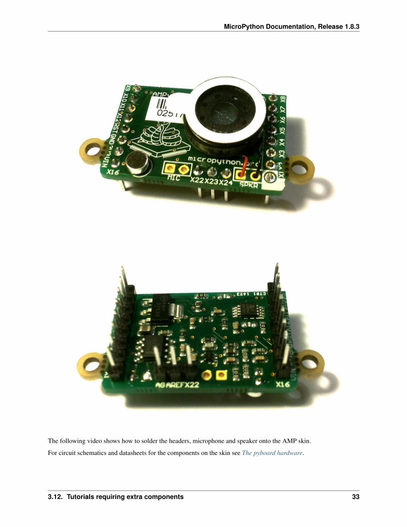
3.12.4 The AMP audio skin
Soldering and using the AMP audio skin.
32 Chapter 3. MicroPython tutorial
MicroPython Documentation, Release 1.8.3
The following video shows how to solder the headers, microphone and speaker onto the AMP skin.
For circuit schematics and datasheets for the components on the skin see The pyboard hardware.
3.12. Tutorials requiring extra components 33
MicroPython Documentation, Release 1.8.3
Example code
The AMP skin has a speaker which is connected to DAC(1) via a small power amplifier. The volume of the amplifieris controlled by a digital potentiometer, which is an I2C device with address 46 on the IC2(1) bus.
To set the volume, define the following function:
import pybdef volume(val):
pyb.I2C(1, pyb.I2C.MASTER).mem_write(val, 46, 0)
Then you can do:
>>> volume(0) # minimum volume>>> volume(127) # maximum volume
To play a sound, use the write_timed method of the DAC object. For example:
import mathfrom pyb import DAC
# create a buffer containing a sine-wavebuf = bytearray(100)for i in range(len(buf)):
buf[i] = 128 + int(127 * math.sin(2 * math.pi * i / len(buf)))
# output the sine-wave at 400Hzdac = DAC(1)dac.write_timed(buf, 400 * len(buf), mode=DAC.CIRCULAR)
You can also play WAV files using the Python wave module. You can get the wave module here and you will alsoneed the chunk module available here. Put these on your pyboard (either on the flash or the SD card in the top-leveldirectory). You will need an 8-bit WAV file to play, such as this one, or to convert any file you have with the command:
avconv -i original.wav -ar 22050 -codec pcm_u8 test.wav
Then you can do:
>>> import wave>>> from pyb import DAC>>> dac = DAC(1)>>> f = wave.open('test.wav')>>> dac.write_timed(f.readframes(f.getnframes()), f.getframerate())
This should play the WAV file.
3.13 Tips, tricks and useful things to know
3.13.1 Debouncing a pin input
A pin used as input from a switch or other mechanical device can have a lot of noise on it, rapidly changing fromlow to high when the switch is first pressed or released. This noise can be eliminated using a capacitor (a debouncingcircuit). It can also be eliminated using a simple function that makes sure the value on the pin is stable.
The following function does just this. It gets the current value of the given pin, and then waits for the value to change.The new pin value must be stable for a continuous 20ms for it to register the change. You can adjust this time (to say50ms) if you still have noise.
34 Chapter 3. MicroPython tutorial
MicroPython Documentation, Release 1.8.3
import pyb
def wait_pin_change(pin):# wait for pin to change value# it needs to be stable for a continuous 20mscur_value = pin.value()active = 0while active < 20:
if pin.value() != cur_value:active += 1
else:active = 0
pyb.delay(1)
Use it something like this:
import pyb
pin_x1 = pyb.Pin('X1', pyb.Pin.IN, pyb.Pin.PULL_DOWN)while True:
wait_pin_change(pin_x1)pyb.LED(4).toggle()
3.13.2 Making a UART - USB pass through
It’s as simple as:
import pybimport select
def pass_through(usb, uart):usb.setinterrupt(-1)while True:
select.select([usb, uart], [], [])if usb.any():
uart.write(usb.read(256))if uart.any():
usb.write(uart.read(256))
pass_through(pyb.USB_VCP(), pyb.UART(1, 9600))
3.13. Tips, tricks and useful things to know 35

MicroPython Documentation, Release 1.8.3
36 Chapter 3. MicroPython tutorial
CHAPTER
FOUR
MICROPYTHON LIBRARIES
This chapter describes modules (function and class libraries) which are built into MicroPython. There are a fewcategories of modules:
• Modules which implement a subset of standard Python functionality and are not intended to be extended by theuser.
• Modules which implement a subset of Python functionality, with a provision for extension by the user (viaPython code).
• Modules which implement MicroPython extensions to the Python standard libraries.
• Modules specific to a particular port and thus not portable.
Note about the availability of modules and their contents: This documentation in general aspires to describe all mod-ules and functions/classes which are implemented in MicroPython. However, MicroPython is highly configurable,and each port to a particular board/embedded system makes available only a subset of MicroPython libraries. Forofficially supported ports, there is an effort to either filter out non-applicable items, or mark individual descriptionswith “Availability:” clauses describing which ports provide a given feature. With that in mind, please still be warnedthat some functions/classes in a module (or even the entire module) described in this documentation may be unavail-able in a particular build of MicroPython on a particular board. The best place to find general information of theavailability/non-availability of a particular feature is the “General Information” section which contains informationpertaining to a specific port.
Beyond the built-in libraries described in this documentation, many more modules from the Python standard library,as well as further MicroPython extensions to it, can be found in the micropython-lib repository.
4.1 Python standard libraries and micro-libraries
The following standard Python libraries have been “micro-ified” to fit in with the philosophy of MicroPython. Theyprovide the core functionality of that module and are intended to be a drop-in replacement for the standard Pythonlibrary.
The modules are available by their u-name, and also by their non-u-name. The non-u-name can be overridden by afile of that name in your package path. For example, import json will first search for a file json.py or directoryjson and load that package if it is found. If nothing is found, it will fallback to loading the built-in ujson module.
4.1.1 array – arrays of numeric data
See Python array for more information.
Supported format codes: b, B, h, H, i, I, l, L, q, Q, f, d (the latter 2 depending on the floating-point support).
37
MicroPython Documentation, Release 1.8.3
Classes
class array.array(typecode[, iterable])Create array with elements of given type. Initial contents of the array are given by an iterable. If it is notprovided, an empty array is created.
append(val)Append new element to the end of array, growing it.
extend(iterable)Append new elements as contained in an iterable to the end of array, growing it.
4.1.2 Builtin Functions
All builtin functions are described here. They are also available via builtins module.
abs()
all()
any()
bin()
class bool
class bytearray
class bytes
callable()
chr()
classmethod()
compile()
class complex
class dict
dir()
divmod()
enumerate()
eval()
exec()
filter()
class float
class frozenset
getattr()
globals()
hasattr()
hash()
hex()
38 Chapter 4. MicroPython libraries

MicroPython Documentation, Release 1.8.3
id()
input()
class int
isinstance()
issubclass()
iter()
len()
class list
locals()
map()
max()
class memoryview
min()
next()
class object
oct()
open()
ord()
pow()
print()
property()
range()
repr()
reversed()
round()
class set
setattr()
sorted()
staticmethod()
class str
sum()
super()
class tuple
type()
zip()
4.1. Python standard libraries and micro-libraries 39
MicroPython Documentation, Release 1.8.3
4.1.3 cmath – mathematical functions for complex numbers
The cmath module provides some basic mathematical functions for working with complex numbers.
Availability: not available on WiPy and ESP8266. Floating point support required for this module.
Functions
cmath.cos(z)Return the cosine of z.
cmath.exp(z)Return the exponential of z.
cmath.log(z)Return the natural logarithm of z. The branch cut is along the negative real axis.
cmath.log10(z)Return the base-10 logarithm of z. The branch cut is along the negative real axis.
cmath.phase(z)Returns the phase of the number z, in the range (-pi, +pi].
cmath.polar(z)Returns, as a tuple, the polar form of z.
cmath.rect(r, phi)Returns the complex number with modulus r and phase phi.
cmath.sin(z)Return the sine of z.
cmath.sqrt(z)Return the square-root of z.
Constants
cmath.ebase of the natural logarithm
cmath.pithe ratio of a circle’s circumference to its diameter
4.1.4 gc – control the garbage collector
Functions
gc.enable()Enable automatic garbage collection.
gc.disable()Disable automatic garbage collection. Heap memory can still be allocated, and garbage collection can still beinitiated manually using gc.collect().
gc.collect()Run a garbage collection.
40 Chapter 4. MicroPython libraries
MicroPython Documentation, Release 1.8.3
gc.mem_alloc()Return the number of bytes of heap RAM that are allocated.
gc.mem_free()Return the number of bytes of available heap RAM.
4.1.5 math – mathematical functions
The math module provides some basic mathematical functions for working with floating-point numbers.
Note: On the pyboard, floating-point numbers have 32-bit precision.
Availability: not available on WiPy. Floating point support required for this module.
Functions
math.acos(x)Return the inverse cosine of x.
math.acosh(x)Return the inverse hyperbolic cosine of x.
math.asin(x)Return the inverse sine of x.
math.asinh(x)Return the inverse hyperbolic sine of x.
math.atan(x)Return the inverse tangent of x.
math.atan2(y, x)Return the principal value of the inverse tangent of y/x.
math.atanh(x)Return the inverse hyperbolic tangent of x.
math.ceil(x)Return an integer, being x rounded towards positive infinity.
math.copysign(x, y)Return x with the sign of y.
math.cos(x)Return the cosine of x.
math.cosh(x)Return the hyperbolic cosine of x.
math.degrees(x)Return radians x converted to degrees.
math.erf(x)Return the error function of x.
math.erfc(x)Return the complementary error function of x.
math.exp(x)Return the exponential of x.
4.1. Python standard libraries and micro-libraries 41
MicroPython Documentation, Release 1.8.3
math.expm1(x)Return exp(x) - 1.
math.fabs(x)Return the absolute value of x.
math.floor(x)Return an integer, being x rounded towards negative infinity.
math.fmod(x, y)Return the remainder of x/y.
math.frexp(x)Decomposes a floating-point number into its mantissa and exponent. The returned value is the tuple (m, e)such that x == m * 2**e exactly. If x == 0 then the function returns (0.0, 0), otherwise the relation0.5 <= abs(m) < 1 holds.
math.gamma(x)Return the gamma function of x.
math.isfinite(x)Return True if x is finite.
math.isinf(x)Return True if x is infinite.
math.isnan(x)Return True if x is not-a-number
math.ldexp(x, exp)Return x * (2**exp).
math.lgamma(x)Return the natural logarithm of the gamma function of x.
math.log(x)Return the natural logarithm of x.
math.log10(x)Return the base-10 logarithm of x.
math.log2(x)Return the base-2 logarithm of x.
math.modf(x)Return a tuple of two floats, being the fractional and integral parts of x. Both return values have the same signas x.
math.pow(x, y)Returns x to the power of y.
math.radians(x)Return degrees x converted to radians.
math.sin(x)Return the sine of x.
math.sinh(x)Return the hyperbolic sine of x.
math.sqrt(x)Return the square root of x.
42 Chapter 4. MicroPython libraries
MicroPython Documentation, Release 1.8.3
math.tan(x)Return the tangent of x.
math.tanh(x)Return the hyperbolic tangent of x.
math.trunc(x)Return an integer, being x rounded towards 0.
Constants
math.ebase of the natural logarithm
math.pithe ratio of a circle’s circumference to its diameter
4.1.6 select – wait for events on a set of streams
This module provides functions to wait for events on streams (select streams which are ready for operations).
Pyboard specifics
Polling is an efficient way of waiting for read/write activity on multiple objects. Current objects that support pollingare: pyb.UART, pyb.USB_VCP.
Functions
select.poll()Create an instance of the Poll class.
select.select(rlist, wlist, xlist[, timeout ])Wait for activity on a set of objects.
This function is provided for compatibility and is not efficient. Usage of Poll is recommended instead.
class Poll
Methods
poll.register(obj[, eventmask ])Register obj for polling. eventmask is logical OR of:
•select.POLLIN - data available for reading
•select.POLLOUT - more data can be written
•select.POLLERR - error occurred
•select.POLLHUP - end of stream/connection termination detected
eventmask defaults to select.POLLIN | select.POLLOUT.
poll.unregister(obj)Unregister obj from polling.
4.1. Python standard libraries and micro-libraries 43
MicroPython Documentation, Release 1.8.3
poll.modify(obj, eventmask)Modify the eventmask for obj.
poll.poll([timeout ])Wait for at least one of the registered objects to become ready. Returns list of (obj, event, ...) tuples,event element specifies which events happened with a stream and is a combination of select.POLL* constantsdescribed above. There may be other elements in tuple, depending on a platform and version, so don’t assumethat its size is 2. In case of timeout, an empty list is returned.
Timeout is in milliseconds.
4.1.7 sys – system specific functions
Functions
sys.exit(retval=0)Terminate current program with a given exit code. Underlyingly, this function raise as SystemExit exception.If an argument is given, its value given as an argument to SystemExit.
sys.print_exception(exc, file=sys.stdout)Print exception with a traceback to a file-like object file (or sys.stdout by default).
Difference to CPython
This is simplified version of a function which appears in the traceback module in CPython. Unliketraceback.print_exception(), this function takes just exception value instead of exception type, ex-ception value, and traceback object; file argument should be positional; further arguments are not supported.CPython-compatible traceback module can be found in micropython-lib.
Constants
sys.argvA mutable list of arguments the current program was started with.
sys.byteorderThe byte order of the system (“little” or “big”).
sys.implementationObject with information about the current Python implementation. For MicroPython, it has following attributes:
•name - string “micropython”
•version - tuple (major, minor, micro), e.g. (1, 7, 0)
This object is the recommended way to distinguish MicroPython from other Python implementations (note thatit still may not exist in the very minimal ports).
Difference to CPython
CPython mandates more attributes for this object, but the actual useful bare minimum is implemented in Mi-croPython.
sys.maxsizeMaximum value which a native integer type can hold on the current platform, or maximum value representable
44 Chapter 4. MicroPython libraries
MicroPython Documentation, Release 1.8.3
by MicroPython integer type, if it’s smaller than platform max value (that is the case for MicroPython portswithout long int support).
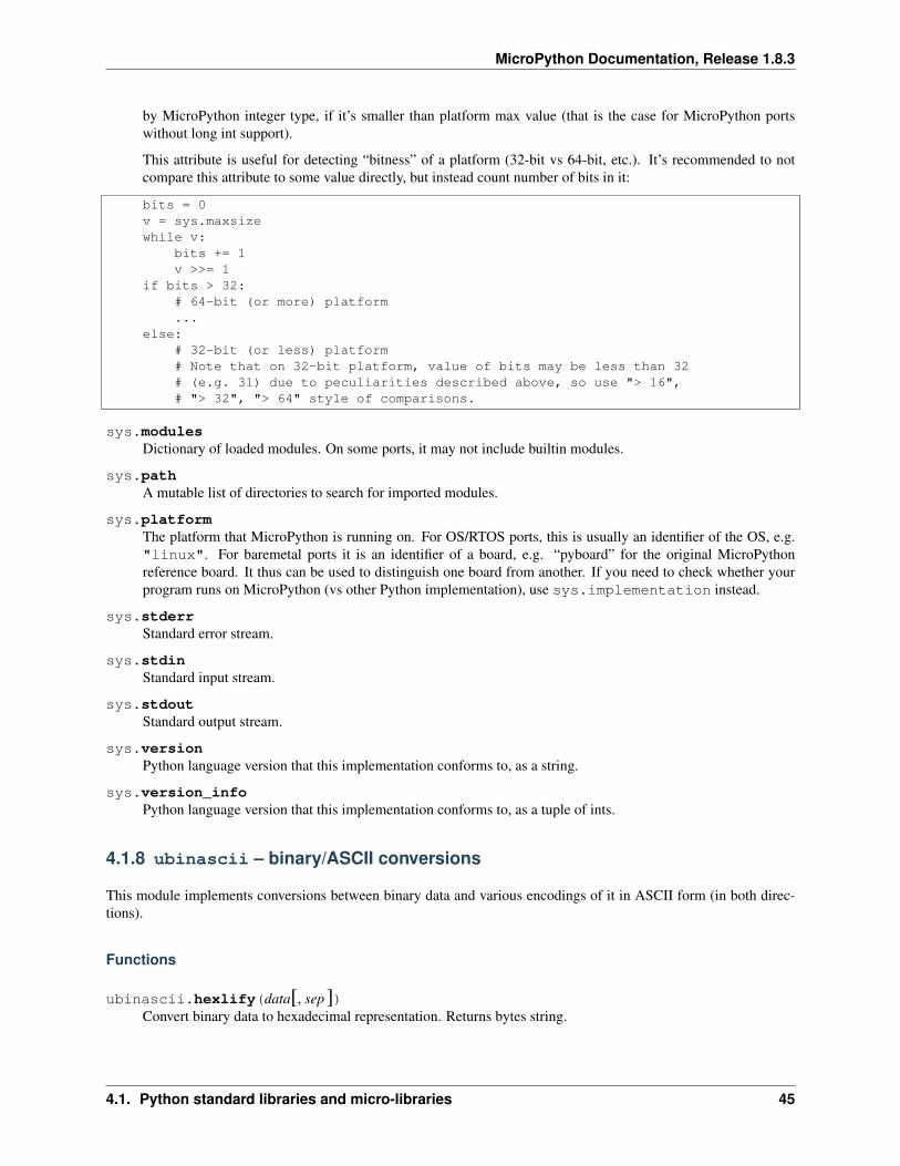
This attribute is useful for detecting “bitness” of a platform (32-bit vs 64-bit, etc.). It’s recommended to notcompare this attribute to some value directly, but instead count number of bits in it:
bits = 0v = sys.maxsizewhile v:
bits += 1v >>= 1
if bits > 32:# 64-bit (or more) platform...
else:# 32-bit (or less) platform# Note that on 32-bit platform, value of bits may be less than 32# (e.g. 31) due to peculiarities described above, so use "> 16",# "> 32", "> 64" style of comparisons.
sys.modulesDictionary of loaded modules. On some ports, it may not include builtin modules.
sys.pathA mutable list of directories to search for imported modules.
sys.platformThe platform that MicroPython is running on. For OS/RTOS ports, this is usually an identifier of the OS, e.g."linux". For baremetal ports it is an identifier of a board, e.g. “pyboard” for the original MicroPythonreference board. It thus can be used to distinguish one board from another. If you need to check whether yourprogram runs on MicroPython (vs other Python implementation), use sys.implementation instead.
sys.stderrStandard error stream.
sys.stdinStandard input stream.
sys.stdoutStandard output stream.
sys.versionPython language version that this implementation conforms to, as a string.
sys.version_infoPython language version that this implementation conforms to, as a tuple of ints.
4.1.8 ubinascii – binary/ASCII conversions
This module implements conversions between binary data and various encodings of it in ASCII form (in both direc-tions).
Functions
ubinascii.hexlify(data[, sep])Convert binary data to hexadecimal representation. Returns bytes string.
4.1. Python standard libraries and micro-libraries 45
MicroPython Documentation, Release 1.8.3
Difference to CPython
If additional argument, sep is supplied, it is used as a separator between hexadecimal values.
ubinascii.unhexlify(data)Convert hexadecimal data to binary representation. Returns bytes string. (i.e. inverse of hexlify)
ubinascii.a2b_base64(data)Convert Base64-encoded data to binary representation. Returns bytes string.
ubinascii.b2a_base64(data)Encode binary data in Base64 format. Returns string.
4.1.9 ucollections – collection and container types
This module implements advanced collection and container types to hold/accumulate various objects.
Classes
ucollections.namedtuple(name, fields)This is factory function to create a new namedtuple type with a specific name and set of fields. A namedtuple isa subclass of tuple which allows to access its fields not just by numeric index, but also with an attribute accesssyntax using symbolic field names. Fields is a sequence of strings specifying field names. For compatibilitywith CPython it can also be a a string with space-separated field named (but this is less efficient). Example ofuse:
from ucollections import namedtuple
MyTuple = namedtuple("MyTuple", ("id", "name"))t1 = MyTuple(1, "foo")t2 = MyTuple(2, "bar")print(t1.name)assert t2.name == t2[1]
ucollections.OrderedDict(...)dict type subclass which remembers and preserves the order of keys added. When ordered dict is iterated over,keys/items are returned in the order they were added:
from ucollections import OrderedDict
# To make benefit of ordered keys, OrderedDict should be initialized# from sequence of (key, value) pairs.d = OrderedDict([("z", 1), ("a", 2)])# More items can be added as usuald["w"] = 5d["b"] = 3for k, v in d.items():
print(k, v)
Output:
z 1a 2w 5b 3
46 Chapter 4. MicroPython libraries
MicroPython Documentation, Release 1.8.3
4.1.10 uhashlib – hashing algorithm
This module implements binary data hashing algorithms. Currently, it implements SHA256 algorithm. ChoosingSHA256 was a deliberate choice, as a modern, cryptographically secure algorithm. This means that a single algorithmcan cover both use cases of “any hash algorithm” and security-related usage, and thus save space omitting legacyalgorithms like MD5 or SHA1.
Constructors
class uhashlib.sha256([data])Create a hasher object and optionally feed data into it.
Methods
hash.update(data)Feed more binary data into hash.
hash.digest()Return hash for all data passed through hash, as a bytes object. After this method is called, more data cannot befed into hash any longer.
hash.hexdigest()This method is NOT implemented. Use ubinascii.hexlify(hash.digest()) to achieve a similareffect.
4.1.11 uheapq – heap queue algorithm
This module implements the heap queue algorithm.
A heap queue is simply a list that has its elements stored in a certain way.
Functions
uheapq.heappush(heap, item)Push the item onto the heap.
uheapq.heappop(heap)Pop the first item from the heap, and return it. Raises IndexError if heap is empty.
uheapq.heapify(x)Convert the list x into a heap. This is an in-place operation.
4.1.12 uio – input/output streams
This module contains additional types of stream (file-like) objects and helper functions.
Functions
uio.open(name, mode=’r’, **kwargs)Open a file. Builtin open() function is aliased to this function. All ports (which provide access to file system)are required to support mode parameter, but support for other arguments vary by port.
4.1. Python standard libraries and micro-libraries 47
MicroPython Documentation, Release 1.8.3
Classes
class uio.FileIO(...)This is type of a file open in binary mode, e.g. using open(name, "rb"). You should not instantiate thisclass directly.
class uio.TextIOWrapper(...)This is type of a file open in text mode, e.g. using open(name, "rt"). You should not instantiate this classdirectly.
class uio.StringIO([string])class uio.BytesIO([string])
In-memory file-like objects for input/output. StringIO is used for text-mode I/O (similar to a normal file openedwith “t” modifier). BytesIO is used for binary-mode I/O (similar to a normal file opened with “b” modifier).Initial contents of file-like objects can be specified with string parameter (should be normal string for StringIO orbytes object for BytesIO). All the usual file methods like read(), write(), seek(), flush(), close()are available on these objects, and additionally, a following method:
getvalue()Get the current contents of the underlying buffer which holds data.
4.1.13 ujson – JSON encoding and decoding
This modules allows to convert between Python objects and the JSON data format.
Functions
ujson.dumps(obj)Return obj represented as a JSON string.
ujson.loads(str)Parse the JSON str and return an object. Raises ValueError if the string is not correctly formed.
4.1.14 uos – basic “operating system” services
The os module contains functions for filesystem access and urandom function.
Port specifics
The filesystem has / as the root directory and the available physical drives are accessible from here. They are currently:
/flash – the internal flash filesystem
/sd – the SD card (if it exists)
On boot up, the current directory is /flash if no SD card is inserted, otherwise it is /sd.
Functions
uos.chdir(path)Change current directory.
uos.getcwd()Get the current directory.
48 Chapter 4. MicroPython libraries
MicroPython Documentation, Release 1.8.3
uos.listdir([dir ])With no argument, list the current directory. Otherwise list the given directory.
uos.mkdir(path)Create a new directory.
uos.remove(path)Remove a file.
uos.rmdir(path)Remove a directory.
uos.rename(old_path, new_path)Rename a file.
uos.stat(path)Get the status of a file or directory.
uos.sync()Sync all filesystems.
uos.urandom(n)Return a bytes object with n random bytes, generated by the hardware random number generator.
Constants
uos.sepseparation character used in paths
4.1.15 ure – regular expressions
This module implements regular expression operations. Regular expression syntax supported is a subset of CPythonre module (and actually is a subset of POSIX extended regular expressions).
Supported operators are:
’.’ Match any character.
’[]’ Match set of characters. Individual characters and ranges are supported.
’^’
’$’
’?’
’*’
’+’
’??’
’*?’
’+?’
Counted repetitions ({m,n}), more advanced assertions, named groups, etc. are not supported.
4.1. Python standard libraries and micro-libraries 49
MicroPython Documentation, Release 1.8.3
Functions
ure.compile(regex)Compile regular expression, return regex object.
ure.match(regex, string)Match regex against string. Match always happens from starting position in a string.
ure.search(regex, string)Search regex in a string. Unlike match, this will search string for first position which matches regex(which still may be 0 if regex is anchored).
ure.DEBUGFlag value, display debug information about compiled expression.
Regex objects
Compiled regular expression. Instances of this class are created using ure.compile().
regex.match(string)
regex.search(string)
regex.split(string, max_split=-1)
Match objects
Match objects as returned by match() and search() methods.
match.group([index ])Only numeric groups are supported.
4.1.16 usocket – socket module
This module provides access to the BSD socket interface.
See corresponding CPython module for comparison.
Socket address format(s)
Functions below which expect a network address, accept it in the format of (ipv4_address, port), where ipv4_addressis a string with dot-notation numeric IPv4 address, e.g. "8.8.8.8", and port is integer port number in therange 1-65535. Note the domain names are not accepted as ipv4_address, they should be resolved first usingsocket.getaddrinfo().
Functions
socket.socket(socket.AF_INET, socket.SOCK_STREAM, socket.IPPROTO_TCP)Create a new socket using the given address family, socket type and protocol number.
socket.getaddrinfo(host, port)Translate the host/port argument into a sequence of 5-tuples that contain all the necessary arguments for creatinga socket connected to that service. The list of 5-tuples has following structure:
50 Chapter 4. MicroPython libraries
MicroPython Documentation, Release 1.8.3
(family, type, proto, canonname, sockaddr)
The following example shows how to connect to a given url:
s = socket.socket()s.connect(socket.getaddrinfo('www.micropython.org', 80)[0][-1])
Constants
socket.AF_INETfamily types
socket.SOCK_STREAM
socket.SOCK_DGRAMsocket types
socket.IPPROTO_UDP
socket.IPPROTO_TCP
class socket
Methods
socket.close()Mark the socket closed. Once that happens, all future operations on the socket object will fail. Theremote end will receive no more data (after queued data is flushed).
Sockets are automatically closed when they are garbage-collected, but it is recommended to close()them explicitly, or to use a with statement around them.
socket.bind(address)Bind the socket to address. The socket must not already be bound.
socket.listen([backlog])Enable a server to accept connections. If backlog is specified, it must be at least 0 (if it’s lower,it will be set to 0); and specifies the number of unaccepted connections that the system will allowbefore refusing new connections. If not specified, a default reasonable value is chosen.
socket.accept()Accept a connection. The socket must be bound to an address and listening for connections. Thereturn value is a pair (conn, address) where conn is a new socket object usable to send and receivedata on the connection, and address is the address bound to the socket on the other end of theconnection.
socket.connect(address)Connect to a remote socket at address.
socket.send(bytes)Send data to the socket. The socket must be connected to a remote socket.
socket.sendall(bytes)Send data to the socket. The socket must be connected to a remote socket.
socket.recv(bufsize)Receive data from the socket. The return value is a bytes object representing the data received. Themaximum amount of data to be received at once is specified by bufsize.
4.1. Python standard libraries and micro-libraries 51
MicroPython Documentation, Release 1.8.3
socket.sendto(bytes, address)Send data to the socket. The socket should not be connected to a remote socket, since the destinationsocket is specified by address.
socket.recvfrom(bufsize)Receive data from the socket. The return value is a pair (bytes, address) where bytes is a bytes objectrepresenting the data received and address is the address of the socket sending the data.
socket.setsockopt(level, optname, value)Set the value of the given socket option. The needed symbolic constants are defined in the socketmodule (SO_* etc.). The value can be an integer or a bytes-like object representing a buffer.
socket.settimeout(value)Set a timeout on blocking socket operations. The value argument can be a nonnegative floating pointnumber expressing seconds, or None. If a non-zero value is given, subsequent socket operations willraise a timeout exception if the timeout period value has elapsed before the operation has completed.If zero is given, the socket is put in non-blocking mode. If None is given, the socket is put in blockingmode.
socket.setblocking(flag)Set blocking or non-blocking mode of the socket: if flag is false, the socket is set to non-blocking,else to blocking mode.
This method is a shorthand for certain settimeout() calls:
sock.setblocking(True) is equivalent to sock.settimeout(None)sock.setblocking(False) is equivalent to sock.settimeout(0.0)
socket.makefile(mode=’rb’)Return a file object associated with the socket. The exact returned type depends on the argumentsgiven to makefile(). The support is limited to binary modes only (‘rb’ and ‘wb’). CPython’s argu-ments: encoding, errors and newline are not supported.
The socket must be in blocking mode; it can have a timeout, but the file object’s internal buffer mayend up in a inconsistent state if a timeout occurs.
Difference to CPython
Closing the file object returned by makefile() WILL close the original socket as well.
socket.read(size)Read up to size bytes from the socket. Return a bytes object. If size is not given, it behaves justlike socket.readall(), see below.
socket.readall()Read all data available from the socket until EOF. This function will not return until the socket isclosed.
socket.readinto(buf [, nbytes])Read bytes into the buf. If nbytes is specified then read at most that many bytes. Otherwise, readat most len(buf) bytes.
Return value: number of bytes read and stored into buf.
socket.readline()Read a line, ending in a newline character.
Return value: the line read.
52 Chapter 4. MicroPython libraries
MicroPython Documentation, Release 1.8.3
socket.write(buf)Write the buffer of bytes to the socket.
Return value: number of bytes written.
4.1.17 ustruct – pack and unpack primitive data types
See Python struct for more information.
Supported size/byte order prefixes: @, <, >, !.
Supported format codes: b, B, h, H, i, I, l, L, q, Q, s, P, f, d (the latter 2 depending on the floating-point support).
Functions
ustruct.calcsize(fmt)Return the number of bytes needed to store the given fmt.
ustruct.pack(fmt, v1, v2, ...)Pack the values v1, v2, ... according to the format string fmt. The return value is a bytes object encoding thevalues.
ustruct.pack_into(fmt, buffer, offset, v1, v2, ...)Pack the values v1, v2, ... according to the format string fmt into a buffer starting at offset. offset may be negativeto count from the end of buffer.
ustruct.unpack(fmt, data)Unpack from the data according to the format string fmt. The return value is a tuple of the unpacked values.
ustruct.unpack_from(fmt, data, offset=0)Unpack from the data starting at offset according to the format string fmt. offset may be negative to count fromthe end of buffer. The return value is a tuple of the unpacked values.
4.1.18 utime – time related functions
The utime module provides functions for getting the current time and date, measuring time intervals, and for delays.
Time Epoch: Unix port uses standard for POSIX systems epoch of 1970-01-01 00:00:00 UTC. However, embeddedports use epoch of 2000-01-01 00:00:00 UTC.
Maintaining actual calendar date/time: This requires a Real Time Clock (RTC). On systems with underlyingOS (including some RTOS), an RTC may be implicit. Setting and maintaining actual calendar time is responsi-bility of OS/RTOS and is done outside of MicroPython, it just uses OS API to query date/time. On baremetalports however system time depends on machine.RTC() object. The current calendar time may be set usingmachine.RTC().datetime(tuple) function, and maintained by following means:
• By a backup battery (which may be an additional, optional component for a particular board).
• Using networked time protocol (requires setup by a port/user).
• Set manually by a user on each power-up (many boards then maintain RTC time across hard resets, though somemay require setting it again in such case).
If actual calendar time is not maintained with a system/MicroPython RTC, functions below which require reference tocurrent absolute time may behave not as expected.
4.1. Python standard libraries and micro-libraries 53
MicroPython Documentation, Release 1.8.3
Functions
utime.localtime([secs])Convert a time expressed in seconds since the Epoch (see above) into an 8-tuple which contains: (year, month,mday, hour, minute, second, weekday, yearday) If secs is not provided or None, then the current time from theRTC is used.
•year includes the century (for example 2014).
•month is 1-12
•mday is 1-31
•hour is 0-23
•minute is 0-59
•second is 0-59
•weekday is 0-6 for Mon-Sun
•yearday is 1-366
utime.mktime()This is inverse function of localtime. It’s argument is a full 8-tuple which expresses a time as per localtime. Itreturns an integer which is the number of seconds since Jan 1, 2000.
utime.sleep(seconds)Sleep for the given number of seconds. Seconds can be a floating-point number to sleep for a fractional numberof seconds. Note that other MicroPython ports may not accept floating-point argument, for compatibility withthem use sleep_ms() and sleep_us() functions.
utime.sleep_ms(ms)Delay for given number of milliseconds, should be positive or 0.
utime.sleep_us(us)Delay for given number of microseconds, should be positive or 0
utime.ticks_ms()Returns an increasing millisecond counter with arbitrary reference point, that wraps after some (unspecified)value. The value should be treated as opaque, suitable for use only with ticks_diff().
utime.ticks_us()Just like ticks_ms above, but in microseconds.
utime.ticks_cpu()Similar to ticks_ms and ticks_us, but with higher resolution (usually CPU clocks).
utime.ticks_diff(old, new)Measure period between consecutive calls to ticks_ms(), ticks_us(), or ticks_cpu(). The value returned by thesefunctions may wrap around at any time, so directly subtracting them is not supported. ticks_diff() should beused instead. “old” value should actually precede “new” value in time, or result is undefined. This functionshould not be used to measure arbitrarily long periods of time (because ticks_*() functions wrap around andusually would have short period). The expected usage pattern is implementing event polling with timeout:
# Wait for GPIO pin to be asserted, but at most 500usstart = time.ticks_us()while pin.value() == 0:
if time.ticks_diff(start, time.ticks_us()) > 500:raise TimeoutError
54 Chapter 4. MicroPython libraries
MicroPython Documentation, Release 1.8.3
utime.time()Returns the number of seconds, as an integer, since the Epoch, assuming that underlying RTC is set and main-tained as described above. If an RTC is not set, this function returns number of seconds since a port-specificreference point in time (for embedded boards without a battery-backed RTC, usually since power up or reset).If you want to develop portable MicroPython application, you should not rely on this function to provide higherthan second precision. If you need higher precision, use ticks_ms() and ticks_us() functions, if youneed calendar time, localtime() without an argument is a better choice.
Difference to CPython
In CPython, this function returns number of seconds since Unix epoch, 1970-01-01 00:00 UTC, as a floating-point, usually having microsecond precision. With MicroPython, only Unix port uses the same Epoch, and iffloating-point precision allows, returns sub-second precision. Embedded hardware usually doesn’t have floating-point precision to represent both long time ranges and subsecond precision, so they use integer value with secondprecision. Some embedded hardware also lacks battery-powered RTC, so returns number of seconds since lastpower-up or from other relative, hardware-specific point (e.g. reset).
4.1.19 uzlib – zlib decompression
This modules allows to decompress binary data compressed with DEFLATE algorithm (commonly used in zlib libraryand gzip archiver). Compression is not yet implemented.
Functions
uzlib.decompress(data)Return decompressed data as bytes.
4.2 MicroPython-specific libraries
Functionality specific to the MicroPython implementation is available in the following libraries.
4.2.1 machine — functions related to the board
The machine module contains specific functions related to the board.
Reset related functions
machine.reset()Resets the device in a manner similar to pushing the external RESET button.
machine.reset_cause()Get the reset cause. See constants for the possible return values.
Interrupt related functions
machine.disable_irq()Disable interrupt requests. Returns the previous IRQ state: False/True for disabled/enabled IRQs respec-tively. This return value can be passed to enable_irq to restore the IRQ to its original state.
4.2. MicroPython-specific libraries 55
MicroPython Documentation, Release 1.8.3
machine.enable_irq(state=True)Enable interrupt requests. If state is True (the default value) then IRQs are enabled. If state is Falsethen IRQs are disabled. The most common use of this function is to pass it the value returned by disable_irqto exit a critical section.
Power related functions
machine.freq()Returns CPU frequency in hertz.
machine.idle()Gates the clock to the CPU, useful to reduce power consumption at any time during short or long periods.Peripherals continue working and execution resumes as soon as any interrupt is triggered (on many ports thisincludes system timer interrupt occurring at regular intervals on the order of millisecond).
machine.sleep()Stops the CPU and disables all peripherals except for WLAN. Execution is resumed from the point where thesleep was requested. For wake up to actually happen, wake sources should be configured first.
machine.deepsleep()Stops the CPU and all peripherals (including networking interfaces, if any). Execution is resumed fromthe main script, just as with a reset. The reset cause can be checked to know that we are coming frommachine.DEEPSLEEP. For wake up to actually happen, wake sources should be configured first, like Pinchange or RTC timeout.
Miscellaneous functions
machine.unique_id()Returns a byte string with a unique identifier of a board/SoC. It will vary from a board/SoC instance to another,if underlying hardware allows. Length varies by hardware (so use substring of a full value if you expect a shortID). In some MicroPython ports, ID corresponds to the network MAC address.
machine.time_pulse_us(pin, pulse_level, timeout_us=1000000)Time a pulse on the given pin, and return the duration of the pulse in microseconds. The pulse_level argumentshould be 0 to time a low pulse or 1 to time a high pulse.
The function first waits while the pin input is different to the pulse_level parameter, then times the duration thatthe pin is equal to pulse_level. If the pin is already equal to pulse_level then timing starts straight away.
The function will raise an OSError with ETIMEDOUT if either of the waits is longer than the given timeoutvalue (which is in microseconds).
Constants
machine.IDLE
machine.SLEEP
machine.DEEPSLEEPirq wake values
machine.POWER_ON
machine.HARD_RESET
machine.WDT_RESET
machine.DEEPSLEEP_RESET
56 Chapter 4. MicroPython libraries
MicroPython Documentation, Release 1.8.3
machine.SOFT_RESETreset causes
machine.WLAN_WAKE
machine.PIN_WAKE
machine.RTC_WAKEwake reasons
Classes
class ADC – analog to digital conversion
Usage:
import machine
adc = machine.ADC() # create an ADC objectapin = adc.channel(pin='GP3') # create an analog pin on GP3val = apin() # read an analog value
Constructorsclass machine.ADC(id=0, *, bits=12)
Create an ADC object associated with the given pin. This allows you to then read analog values on that pin. Formore info check the pinout and alternate functions table.
Warning: ADC pin input range is 0-1.4V (being 1.8V the absolute maximum that it can withstand). WhenGP2, GP3, GP4 or GP5 are remapped to the ADC block, 1.8 V is the maximum. If these pins are used indigital mode, then the maximum allowed input is 3.6V.
MethodsADC.channel(id, *, pin)
Create an analog pin. If only channel ID is given, the correct pin will be selected. Alternatively, only the pincan be passed and the correct channel will be selected. Examples:
# all of these are equivalent and enable ADC channel 1 on GP3apin = adc.channel(1)apin = adc.channel(pin='GP3')apin = adc.channel(id=1, pin='GP3')
ADC.init()Enable the ADC block.
ADC.deinit()Disable the ADC block.
class ADCChannel — read analog values from internal or external sources
ADC channels can be connected to internal points of the MCU or to GPIO pins. ADC channels are created using theADC.channel method.
machine.adcchannel()Fast method to read the channel value.
4.2. MicroPython-specific libraries 57
MicroPython Documentation, Release 1.8.3
adcchannel.value()Read the channel value.
adcchannel.init()Re-init (and effectively enable) the ADC channel.
adcchannel.deinit()Disable the ADC channel.
class I2C – a two-wire serial protocol
I2C is a two-wire protocol for communicating between devices. At the physical level it consists of 2 wires: SCL andSDA, the clock and data lines respectively.
I2C objects are created attached to a specific bus. They can be initialised when created, or initialised later on.
Printing the i2c object gives you information about its configuration.
Constructors
General MethodsI2C.deinit()
Turn off the I2C bus.
Availability: WiPy.I2C.scan()
Scan all I2C addresses between 0x08 and 0x77 inclusive and return a list of those that respond. A deviceresponds if it pulls the SDA line low after its address (including a read bit) is sent on the bus.
Note: on WiPy the I2C object must be in master mode for this method to be valid.
Primitive I2C operations The following methods implement the primitive I2C master bus operations and can becombined to make any I2C transaction. They are provided if you need more control over the bus, otherwise thestandard methods (see below) can be used.
I2C.start()Send a start bit on the bus (SDA transitions to low while SCL is high).
Availability: ESP8266.
I2C.stop()Send a stop bit on the bus (SDA transitions to high while SCL is high).
Availability: ESP8266.
I2C.readinto(buf)Reads bytes from the bus and stores them into buf. The number of bytes read is the length of buf. An ACK willbe sent on the bus after receiving all but the last byte, and a NACK will be sent following the last byte.
Availability: ESP8266.
I2C.write(buf)Write all the bytes from buf to the bus. Checks that an ACK is received after each byte and raises an OSError ifnot.
Availability: ESP8266.
58 Chapter 4. MicroPython libraries
MicroPython Documentation, Release 1.8.3
Standard bus operations The following methods implement the standard I2C master read and write operations thattarget a given slave device.
I2C.readfrom(addr, nbytes)Read nbytes from the slave specified by addr. Returns a bytes object with the data read.
I2C.readfrom_into(addr, buf)Read into buf from the slave specified by addr. The number of bytes read will be the length of buf.
On WiPy the return value is the number of bytes read. Otherwise the return value is None.
I2C.writeto(addr, buf, *, stop=True)Write the bytes from buf to the slave specified by addr.
The stop argument (only available on WiPy) tells if a stop bit should be sent at the end of the transfer. If Falsethe transfer should be continued later on.
On WiPy the return value is the number of bytes written. Otherwise the return value is None.
Memory operations Some I2C devices act as a memory device (or set of registers) that can be read from and writtento. In this case there are two addresses associated with an I2C transaction: the slave address and the memory address.The following methods are convenience functions to communicate with such devices.
I2C.readfrom_mem(addr, memaddr, nbytes, *, addrsize=8)Read nbytes from the slave specified by addr starting from the memory address specified by memaddr. Theargument addrsize specifies the address size in bits (on ESP8266 this argument is not recognised and the addresssize is always 8 bits). Returns a bytes object with the data read.
I2C.readfrom_mem_into(addr, memaddr, buf, *, addrsize=8)Read into buf from the slave specified by addr starting from the memory address specified by memaddr. Thenumber of bytes read is the length of buf. The argument addrsize specifies the address size in bits (on ESP8266this argument is not recognised and the address size is always 8 bits).
On WiPy the return value is the number of bytes read. Otherwise the return value is None.
I2C.writeto_mem(addr, memaddr, buf, *, addrsize=8)Write buf to the slave specified by addr starting from the memory address specified by memaddr. The argumentaddrsize specifies the address size in bits (on ESP8266 this argument is not recognised and the address size isalways 8 bits).
On WiPy the return value is the number of bytes written. Otherwise the return value is None.
ConstantsI2C.MASTER
for initialising the bus to master mode
Availability: WiPy.
class Pin – control I/O pins
A pin is the basic object to control I/O pins (also known as GPIO - general-purpose input/output). It has methods toset the mode of the pin (input, output, etc) and methods to get and set the digital logic level. For analog control of apin, see the ADC class.
Usage Model:
4.2. MicroPython-specific libraries 59
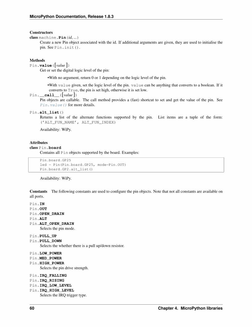
MicroPython Documentation, Release 1.8.3
Constructorsclass machine.Pin(id, ...)
Create a new Pin object associated with the id. If additional arguments are given, they are used to initialise thepin. See Pin.init().
MethodsPin.value([value])
Get or set the digital logic level of the pin:
•With no argument, return 0 or 1 depending on the logic level of the pin.
•With value given, set the logic level of the pin. value can be anything that converts to a boolean. If itconverts to True, the pin is set high, otherwise it is set low.
Pin.__call__([value])Pin objects are callable. The call method provides a (fast) shortcut to set and get the value of the pin. SeePin.value() for more details.
Pin.alt_list()Returns a list of the alternate functions supported by the pin. List items are a tuple of the form:(’ALT_FUN_NAME’, ALT_FUN_INDEX)
Availability: WiPy.
Attributesclass Pin.board
Contains all Pin objects supported by the board. Examples:
Pin.board.GP25led = Pin(Pin.board.GP25, mode=Pin.OUT)Pin.board.GP2.alt_list()
Availability: WiPy.
Constants The following constants are used to configure the pin objects. Note that not all constants are available onall ports.
Pin.INPin.OUTPin.OPEN_DRAINPin.ALTPin.ALT_OPEN_DRAIN
Selects the pin mode.
Pin.PULL_UPPin.PULL_DOWN
Selects the whether there is a pull up/down resistor.
Pin.LOW_POWERPin.MED_POWERPin.HIGH_POWER
Selects the pin drive strength.
Pin.IRQ_FALLINGPin.IRQ_RISINGPin.IRQ_LOW_LEVELPin.IRQ_HIGH_LEVEL
Selects the IRQ trigger type.
60 Chapter 4. MicroPython libraries
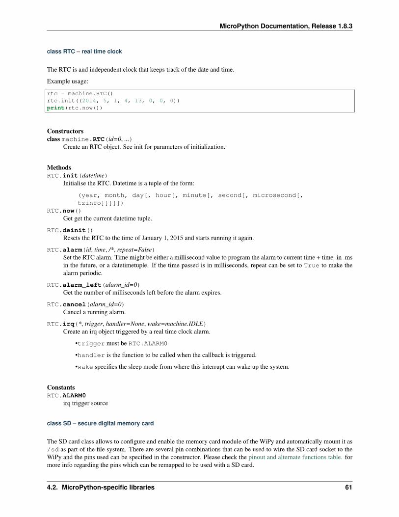
MicroPython Documentation, Release 1.8.3
class RTC – real time clock
The RTC is and independent clock that keeps track of the date and time.
Example usage:
rtc = machine.RTC()rtc.init((2014, 5, 1, 4, 13, 0, 0, 0))print(rtc.now())
Constructorsclass machine.RTC(id=0, ...)
Create an RTC object. See init for parameters of initialization.
MethodsRTC.init(datetime)
Initialise the RTC. Datetime is a tuple of the form:
(year, month, day[, hour[, minute[, second[, microsecond[,tzinfo]]]]])
RTC.now()Get get the current datetime tuple.
RTC.deinit()Resets the RTC to the time of January 1, 2015 and starts running it again.
RTC.alarm(id, time, /*, repeat=False)Set the RTC alarm. Time might be either a millisecond value to program the alarm to current time + time_in_msin the future, or a datetimetuple. If the time passed is in milliseconds, repeat can be set to True to make thealarm periodic.
RTC.alarm_left(alarm_id=0)Get the number of milliseconds left before the alarm expires.
RTC.cancel(alarm_id=0)Cancel a running alarm.
RTC.irq(*, trigger, handler=None, wake=machine.IDLE)Create an irq object triggered by a real time clock alarm.
•trigger must be RTC.ALARM0
•handler is the function to be called when the callback is triggered.
•wake specifies the sleep mode from where this interrupt can wake up the system.
ConstantsRTC.ALARM0
irq trigger source
class SD – secure digital memory card
The SD card class allows to configure and enable the memory card module of the WiPy and automatically mount it as/sd as part of the file system. There are several pin combinations that can be used to wire the SD card socket to theWiPy and the pins used can be specified in the constructor. Please check the pinout and alternate functions table. formore info regarding the pins which can be remapped to be used with a SD card.
4.2. MicroPython-specific libraries 61
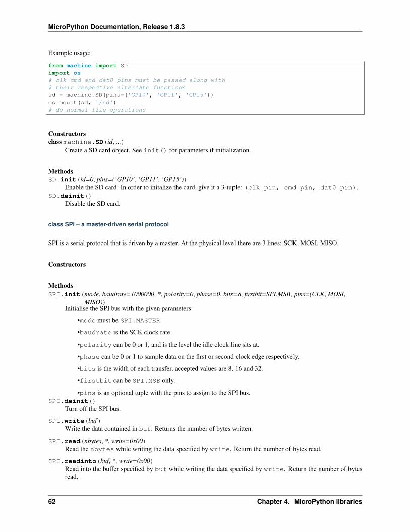
MicroPython Documentation, Release 1.8.3
Example usage:
from machine import SDimport os# clk cmd and dat0 pins must be passed along with# their respective alternate functionssd = machine.SD(pins=('GP10', 'GP11', 'GP15'))os.mount(sd, '/sd')# do normal file operations
Constructorsclass machine.SD(id, ...)
Create a SD card object. See init() for parameters if initialization.
MethodsSD.init(id=0, pins=(‘GP10’, ‘GP11’, ‘GP15’))
Enable the SD card. In order to initalize the card, give it a 3-tuple: (clk_pin, cmd_pin, dat0_pin).SD.deinit()
Disable the SD card.
class SPI – a master-driven serial protocol
SPI is a serial protocol that is driven by a master. At the physical level there are 3 lines: SCK, MOSI, MISO.
Constructors
MethodsSPI.init(mode, baudrate=1000000, *, polarity=0, phase=0, bits=8, firstbit=SPI.MSB, pins=(CLK, MOSI,
MISO))Initialise the SPI bus with the given parameters:
•mode must be SPI.MASTER.
•baudrate is the SCK clock rate.
•polarity can be 0 or 1, and is the level the idle clock line sits at.
•phase can be 0 or 1 to sample data on the first or second clock edge respectively.
•bits is the width of each transfer, accepted values are 8, 16 and 32.
•firstbit can be SPI.MSB only.
•pins is an optional tuple with the pins to assign to the SPI bus.SPI.deinit()
Turn off the SPI bus.
SPI.write(buf)Write the data contained in buf. Returns the number of bytes written.
SPI.read(nbytes, *, write=0x00)Read the nbytes while writing the data specified by write. Return the number of bytes read.
SPI.readinto(buf, *, write=0x00)Read into the buffer specified by buf while writing the data specified by write. Return the number of bytesread.
62 Chapter 4. MicroPython libraries
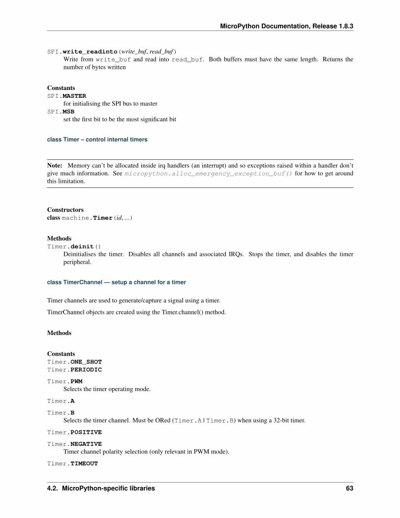
MicroPython Documentation, Release 1.8.3
SPI.write_readinto(write_buf, read_buf)Write from write_buf and read into read_buf. Both buffers must have the same length. Returns thenumber of bytes written
ConstantsSPI.MASTER
for initialising the SPI bus to masterSPI.MSB
set the first bit to be the most significant bit
class Timer – control internal timers
Note: Memory can’t be allocated inside irq handlers (an interrupt) and so exceptions raised within a handler don’tgive much information. See micropython.alloc_emergency_exception_buf() for how to get aroundthis limitation.
Constructorsclass machine.Timer(id, ...)
MethodsTimer.deinit()
Deinitialises the timer. Disables all channels and associated IRQs. Stops the timer, and disables the timerperipheral.
class TimerChannel — setup a channel for a timer
Timer channels are used to generate/capture a signal using a timer.
TimerChannel objects are created using the Timer.channel() method.
Methods
ConstantsTimer.ONE_SHOTTimer.PERIODIC
Timer.PWMSelects the timer operating mode.
Timer.A
Timer.BSelects the timer channel. Must be ORed (Timer.A | Timer.B) when using a 32-bit timer.
Timer.POSITIVE
Timer.NEGATIVETimer channel polarity selection (only relevant in PWM mode).
Timer.TIMEOUT
4.2. MicroPython-specific libraries 63
MicroPython Documentation, Release 1.8.3
Timer.MATCHTimer channel IRQ triggers.
class UART – duplex serial communication bus
UART implements the standard UART/USART duplex serial communications protocol. At the physical level it con-sists of 2 lines: RX and TX. The unit of communication is a character (not to be confused with a string character)which can be 8 or 9 bits wide.
UART objects can be created and initialised using:
from machine import UART
uart = UART(1, 9600) # init with given baudrateuart.init(9600, bits=8, parity=None, stop=1) # init with given parameters
A UART object acts like a stream object and reading and writing is done using the standard stream methods:
uart.read(10) # read 10 characters, returns a bytes objectuart.readall() # read all available charactersuart.readline() # read a lineuart.readinto(buf) # read and store into the given bufferuart.write('abc') # write the 3 characters
Individual characters can be read/written using:
uart.readchar() # read 1 character and returns it as an integeruart.writechar(42) # write 1 character
To check if there is anything to be read, use:
uart.any() # returns True if any characters waiting
Constructors
MethodsUART.deinit()
Turn off the UART bus.UART.any()
Return the number of characters available for reading.
UART.read([nbytes])Read characters. If nbytes is specified then read at most that many bytes.
Return value: a bytes object containing the bytes read in. Returns None on timeout.
UART.readall()Read as much data as possible.
Return value: a bytes object or None on timeout.
UART.readinto(buf [, nbytes])Read bytes into the buf. If nbytes is specified then read at most that many bytes. Otherwise, read at mostlen(buf) bytes.
Return value: number of bytes read and stored into buf or None on timeout.
64 Chapter 4. MicroPython libraries
MicroPython Documentation, Release 1.8.3
UART.readline()Read a line, ending in a newline character.
Return value: the line read or None on timeout.
UART.write(buf)Write the buffer of bytes to the bus.
Return value: number of bytes written or None on timeout.
UART.sendbreak()Send a break condition on the bus. This drives the bus low for a duration of 13 bits. Return value: None.
ConstantsUART.EVENUART.ODD
parity types (along with None)
UART.RX_ANYIRQ trigger sources
class WDT – watchdog timer
The WDT is used to restart the system when the application crashes and ends up into a non recoverable state. Oncestarted it cannot be stopped or reconfigured in any way. After enabling, the application must “feed” the watchdogperiodically to prevent it from expiring and resetting the system.
Example usage:
from machine import WDTwdt = WDT(timeout=2000) # enable it with a timeout of 2swdt.feed()
Constructorsclass machine.WDT(id=0, timeout=5000)
Create a WDT object and start it. The timeout must be given in seconds and the minimum value that is acceptedis 1 second. Once it is running the timeout cannot be changed and the WDT cannot be stopped either.
Methodswdt.feed()
Feed the WDT to prevent it from resetting the system. The application should place this call in a sensible placeensuring that the WDT is only fed after verifying that everything is functioning correctly.
4.2.2 micropython – access and control MicroPython internals
Functions
micropython.mem_info([verbose])Print information about currently used memory. If the verbose argument is given then extra information isprinted.
The information that is printed is implementation dependent, but currently includes the amount of stack andheap used. In verbose mode it prints out the entire heap indicating which blocks are used and which are free.
4.2. MicroPython-specific libraries 65
MicroPython Documentation, Release 1.8.3
micropython.qstr_info([verbose])Print information about currently interned strings. If the verbose argument is given then extra information isprinted.
The information that is printed is implementation dependent, but currently includes the number of internedstrings and the amount of RAM they use. In verbose mode it prints out the names of all RAM-interned strings.
micropython.alloc_emergency_exception_buf(size)Allocate size bytes of RAM for the emergency exception buffer (a good size is around 100 bytes). The bufferis used to create exceptions in cases when normal RAM allocation would fail (eg within an interrupt handler)and therefore give useful traceback information in these situations.
A good way to use this function is to put it at the start of your main script (eg boot.py or main.py) and then theemergency exception buffer will be active for all the code following it.
4.2.3 network — network configuration
This module provides network drivers and routing configuration. Network drivers for specific hardware are availablewithin this module and are used to configure a hardware network interface. Configured interfaces are then availablefor use via the socket module. To use this module the network build of firmware must be installed.
For example:
# configure a specific network interface# see below for examples of specific driversimport networknic = network.Driver(...)print(nic.ifconfig())
# now use socket as usualimport socketaddr = socket.getaddrinfo('micropython.org', 80)[0][-1]s = socket.socket()s.connect(addr)s.send(b'GET / HTTP/1.1\r\nHost: micropython.org\r\n\r\n')data = s.recv(1000)s.close()
class CC3K
This class provides a driver for CC3000 wifi modules. Example usage:
import networknic = network.CC3K(pyb.SPI(2), pyb.Pin.board.Y5, pyb.Pin.board.Y4, pyb.Pin.board.Y3)nic.connect('your-ssid', 'your-password')while not nic.isconnected():
pyb.delay(50)print(nic.ifconfig())
# now use socket as usual...
For this example to work the CC3000 module must have the following connections:
• MOSI connected to Y8
• MISO connected to Y7
66 Chapter 4. MicroPython libraries
MicroPython Documentation, Release 1.8.3
• CLK connected to Y6
• CS connected to Y5
• VBEN connected to Y4
• IRQ connected to Y3
It is possible to use other SPI busses and other pins for CS, VBEN and IRQ.
Constructors
class network.CC3K(spi, pin_cs, pin_en, pin_irq)Create a CC3K driver object, initialise the CC3000 module using the given SPI bus and pins, and return theCC3K object.
Arguments are:
•spi is an SPI object which is the SPI bus that the CC3000 is connected to (the MOSI, MISO and CLKpins).
•pin_cs is a Pin object which is connected to the CC3000 CS pin.
•pin_en is a Pin object which is connected to the CC3000 VBEN pin.
•pin_irq is a Pin object which is connected to the CC3000 IRQ pin.
All of these objects will be initialised by the driver, so there is no need to initialise them yourself. For example,you can use:
nic = network.CC3K(pyb.SPI(2), pyb.Pin.board.Y5, pyb.Pin.board.Y4, pyb.Pin.board.Y3)
Methods
cc3k.connect(ssid, key=None, *, security=WPA2, bssid=None)Connect to a wifi access point using the given SSID, and other security parameters.
cc3k.disconnect()Disconnect from the wifi access point.
cc3k.isconnected()Returns True if connected to a wifi access point and has a valid IP address, False otherwise.
cc3k.ifconfig()Returns a 7-tuple with (ip, subnet mask, gateway, DNS server, DHCP server, MAC address, SSID).
cc3k.patch_version()Return the version of the patch program (firmware) on the CC3000.
cc3k.patch_program(‘pgm’)Upload the current firmware to the CC3000. You must pass ‘pgm’ as the first argument in order for the uploadto proceed.
Constants
CC3K.WEP
CC3K.WPA
4.2. MicroPython-specific libraries 67
MicroPython Documentation, Release 1.8.3
CC3K.WPA2security type to use
class WIZNET5K
This class allows you to control WIZnet5x00 Ethernet adaptors based on the W5200 and W5500 chipsets (only W5200tested).
Example usage:
import networknic = network.WIZNET5K(pyb.SPI(1), pyb.Pin.board.X5, pyb.Pin.board.X4)print(nic.ifconfig())
# now use socket as usual...
For this example to work the WIZnet5x00 module must have the following connections:
• MOSI connected to X8
• MISO connected to X7
• SCLK connected to X6
• nSS connected to X5
• nRESET connected to X4
It is possible to use other SPI busses and other pins for nSS and nRESET.
Constructors
class network.WIZNET5K(spi, pin_cs, pin_rst)Create a WIZNET5K driver object, initialise the WIZnet5x00 module using the given SPI bus and pins, andreturn the WIZNET5K object.
Arguments are:
•spi is an SPI object which is the SPI bus that the WIZnet5x00 is connected to (the MOSI, MISO andSCLK pins).
•pin_cs is a Pin object which is connected to the WIZnet5x00 nSS pin.
•pin_rst is a Pin object which is connected to the WIZnet5x00 nRESET pin.
All of these objects will be initialised by the driver, so there is no need to initialise them yourself. For example,you can use:
nic = network.WIZNET5K(pyb.SPI(1), pyb.Pin.board.X5, pyb.Pin.board.X4)
Methods
wiznet5k.ifconfig([(ip, subnet, gateway, dns)])Get/set IP address, subnet mask, gateway and DNS.
When called with no arguments, this method returns a 4-tuple with the above information.
To set the above values, pass a 4-tuple with the required information. For example:
68 Chapter 4. MicroPython libraries
MicroPython Documentation, Release 1.8.3
nic.ifconfig(('192.168.0.4', '255.255.255.0', '192.168.0.1', '8.8.8.8'))
wiznet5k.regs()Dump the WIZnet5x00 registers. Useful for debugging.
4.2.4 uctypes – access binary data in a structured way
This module implements “foreign data interface” for MicroPython. The idea behind it is similar to CPython’s ctypesmodules, but the actual API is different, streamlined and optimized for small size. The basic idea of the module isto define data structure layout with about the same power as the C language allows, and the access it using familiardot-syntax to reference sub-fields.
See also:
Module ustruct Standard Python way to access binary data structures (doesn’t scale well to large and complexstructures).
Defining structure layout
Structure layout is defined by a “descriptor” - a Python dictionary which encodes field names as keys and otherproperties required to access them as associated values. Currently, uctypes requires explicit specification of offsets foreach field. Offset are given in bytes from a structure start.
Following are encoding examples for various field types:
• Scalar types:
"field_name": uctypes.UINT32 | 0
in other words, value is scalar type identifier ORed with field offset (in bytes) from the start of the structure.
• Recursive structures:
"sub": (2, {"b0": uctypes.UINT8 | 0,"b1": uctypes.UINT8 | 1,
})
i.e. value is a 2-tuple, first element of which is offset, and second is a structure descriptor dictionary (note:offsets in recursive descriptors are relative to a structure it defines).
• Arrays of primitive types:
"arr": (uctypes.ARRAY | 0, uctypes.UINT8 | 2),
i.e. value is a 2-tuple, first element of which is ARRAY flag ORed with offset, and second is scalar element typeORed number of elements in array.
• Arrays of aggregate types:
"arr2": (uctypes.ARRAY | 0, 2, {"b": uctypes.UINT8 | 0}),
i.e. value is a 3-tuple, first element of which is ARRAY flag ORed with offset, second is a number of elementsin array, and third is descriptor of element type.
• Pointer to a primitive type:
"ptr": (uctypes.PTR | 0, uctypes.UINT8),
4.2. MicroPython-specific libraries 69
MicroPython Documentation, Release 1.8.3
i.e. value is a 2-tuple, first element of which is PTR flag ORed with offset, and second is scalar element type.
• Pointer to an aggregate type:
"ptr2": (uctypes.PTR | 0, {"b": uctypes.UINT8 | 0}),
i.e. value is a 2-tuple, first element of which is PTR flag ORed with offset, second is descriptor of type pointedto.
• Bitfields:
"bitf0": uctypes.BFUINT16 | 0 | 0 << uctypes.BF_POS | 8 << uctypes.BF_LEN,
i.e. value is type of scalar value containing given bitfield (typenames are similar to scalar types, but prefixes with“BF”), ORed with offset for scalar value containing the bitfield, and further ORed with values for bit offset andbit length of the bitfield within scalar value, shifted by BF_POS and BF_LEN positions, respectively. Bitfieldposition is counted from the least significant bit, and is the number of right-most bit of a field (in other words,it’s a number of bits a scalar needs to be shifted right to extra the bitfield).
In the example above, first UINT16 value will be extracted at offset 0 (this detail may be important whenaccessing hardware registers, where particular access size and alignment are required), and then bitfield whoserightmost bit is least-significant bit of this UINT16, and length is 8 bits, will be extracted - effectively, this willaccess least-significant byte of UINT16.
Note that bitfield operations are independent of target byte endianness, in particular, example above will accessleast-significant byte of UINT16 in both little- and big-endian structures. But it depends on the least significantbit being numbered 0. Some targets may use different numbering in their native ABI, but uctypes always usesnormalized numbering described above.
Module contents
class uctypes.struct(addr, descriptor, layout_type=NATIVE)Instantiate a “foreign data structure” object based on structure address in memory, descriptor (encoded as adictionary), and layout type (see below).
uctypes.LITTLE_ENDIANLayout type for a little-endian packed structure. (Packed means that every field occupies exactly as many bytesas defined in the descriptor, i.e. the alignment is 1).
uctypes.BIG_ENDIANLayout type for a big-endian packed structure.
uctypes.NATIVELayout type for a native structure - with data endianness and alignment conforming to the ABI of the system onwhich MicroPython runs.
uctypes.sizeof(struct)Return size of data structure in bytes. Argument can be either structure class or specific instantiated structureobject (or its aggregate field).
uctypes.addressof(obj)Return address of an object. Argument should be bytes, bytearray or other object supporting buffer protocol(and address of this buffer is what actually returned).
uctypes.bytes_at(addr, size)Capture memory at the given address and size as bytes object. As bytes object is immutable, memory is actuallyduplicated and copied into bytes object, so if memory contents change later, created object retains original value.
uctypes.bytearray_at(addr, size)Capture memory at the given address and size as bytearray object. Unlike bytes_at() function above, memory
70 Chapter 4. MicroPython libraries
MicroPython Documentation, Release 1.8.3
is captured by reference, so it can be both written too, and you will access current value at the given memoryaddress.
Structure descriptors and instantiating structure objects
Given a structure descriptor dictionary and its layout type, you can instantiate a specific structure instance at a givenmemory address using uctypes.struct() constructor. Memory address usually comes from following sources:
• Predefined address, when accessing hardware registers on a baremetal system. Lookup these addresses indatasheet for a particular MCU/SoC.
• As a return value from a call to some FFI (Foreign Function Interface) function.
• From uctypes.addressof(), when you want to pass arguments to an FFI function, or alternatively, to access somedata for I/O (for example, data read from a file or network socket).
Structure objects
Structure objects allow accessing individual fields using standard dot notation:my_struct.substruct1.field1. If a field is of scalar type, getting it will produce a primitive value(Python integer or float) corresponding to the value contained in a field. A scalar field can also be assigned to.
If a field is an array, its individual elements can be accessed with the standard subscript operator [] - both read andassigned to.
If a field is a pointer, it can be dereferenced using [0] syntax (corresponding to C * operator, though [0] works in Ctoo). Subscripting a pointer with other integer values but 0 are supported too, with the same semantics as in C.
Summing up, accessing structure fields generally follows C syntax, except for pointer dereference, when you need touse [0] operator instead of *.
Limitations
Accessing non-scalar fields leads to allocation of intermediate objects to represent them. This means that special careshould be taken to layout a structure which needs to be accessed when memory allocation is disabled (e.g. from aninterrupt). The recommendations are:
• Avoid nested structures. For example, instead of mcu_registers.peripheral_a.register1, defineseparate layout descriptors for each peripheral, to be accessed as peripheral_a.register1.
• Avoid other non-scalar data, like array. For example, instead of peripheral_a.register[0] useperipheral_a.register0.
Note that these recommendations will lead to decreased readability and conciseness of layouts, so they should be usedonly if the need to access structure fields without allocation is anticipated (it’s even possible to define 2 parallel layouts- one for normal usage, and a restricted one to use when memory allocation is prohibited).
4.3 Libraries specific to the pyboard
The following libraries are specific to the pyboard.
4.3.1 pyb — functions related to the board
The pyb module contains specific functions related to the board.
4.3. Libraries specific to the pyboard 71
MicroPython Documentation, Release 1.8.3
Time related functions
pyb.delay(ms)Delay for the given number of milliseconds.
pyb.udelay(us)Delay for the given number of microseconds.
pyb.millis()Returns the number of milliseconds since the board was last reset.
The result is always a micropython smallint (31-bit signed number), so after 2^30 milliseconds (about 12.4 days)this will start to return negative numbers.
Note that if pyb.stop() is issued the hardware counter supporting this function will pause for the durationof the “sleeping” state. This will affect the outcome of pyb.elapsed_millis().
pyb.micros()Returns the number of microseconds since the board was last reset.
The result is always a micropython smallint (31-bit signed number), so after 2^30 microseconds (about 17.8minutes) this will start to return negative numbers.
Note that if pyb.stop() is issued the hardware counter supporting this function will pause for the durationof the “sleeping” state. This will affect the outcome of pyb.elapsed_micros().
pyb.elapsed_millis(start)Returns the number of milliseconds which have elapsed since start.
This function takes care of counter wrap, and always returns a positive number. This means it can be used tomeasure periods up to about 12.4 days.
Example:
start = pyb.millis()while pyb.elapsed_millis(start) < 1000:
# Perform some operation
pyb.elapsed_micros(start)Returns the number of microseconds which have elapsed since start.
This function takes care of counter wrap, and always returns a positive number. This means it can be used tomeasure periods up to about 17.8 minutes.
Example:
start = pyb.micros()while pyb.elapsed_micros(start) < 1000:
# Perform some operationpass
Reset related functions
pyb.hard_reset()Resets the pyboard in a manner similar to pushing the external RESET button.
pyb.bootloader()Activate the bootloader without BOOT* pins.
72 Chapter 4. MicroPython libraries
MicroPython Documentation, Release 1.8.3
Interrupt related functions
pyb.disable_irq()Disable interrupt requests. Returns the previous IRQ state: False/True for disabled/enabled IRQs respec-tively. This return value can be passed to enable_irq to restore the IRQ to its original state.
pyb.enable_irq(state=True)Enable interrupt requests. If state is True (the default value) then IRQs are enabled. If state is Falsethen IRQs are disabled. The most common use of this function is to pass it the value returned by disable_irqto exit a critical section.
Power related functions
pyb.freq([sysclk[, hclk[, pclk1[, pclk2]]]])If given no arguments, returns a tuple of clock frequencies: (sysclk, hclk, pclk1, pclk2). These correspond to:
•sysclk: frequency of the CPU
•hclk: frequency of the AHB bus, core memory and DMA
•pclk1: frequency of the APB1 bus
•pclk2: frequency of the APB2 bus
If given any arguments then the function sets the frequency of the CPU, and the busses if additional argumentsare given. Frequencies are given in Hz. Eg freq(120000000) sets sysclk (the CPU frequency) to 120MHz. Notethat not all values are supported and the largest supported frequency not greater than the given value will beselected.
Supported sysclk frequencies are (in MHz): 8, 16, 24, 30, 32, 36, 40, 42, 48, 54, 56, 60, 64, 72, 84, 96, 108,120, 144, 168.
The maximum frequency of hclk is 168MHz, of pclk1 is 42MHz, and of pclk2 is 84MHz. Be sure not to setfrequencies above these values.
The hclk, pclk1 and pclk2 frequencies are derived from the sysclk frequency using a prescaler (divider). Sup-ported prescalers for hclk are: 1, 2, 4, 8, 16, 64, 128, 256, 512. Supported prescalers for pclk1 and pclk2 are: 1,2, 4, 8. A prescaler will be chosen to best match the requested frequency.
A sysclk frequency of 8MHz uses the HSE (external crystal) directly and 16MHz uses the HSI (internal oscilla-tor) directly. The higher frequencies use the HSE to drive the PLL (phase locked loop), and then use the outputof the PLL.
Note that if you change the frequency while the USB is enabled then the USB may become unreliable. It isbest to change the frequency in boot.py, before the USB peripheral is started. Also note that sysclk frequenciesbelow 36MHz do not allow the USB to function correctly.
pyb.wfi()Wait for an internal or external interrupt.
This executes a wfi instruction which reduces power consumption of the MCU until any interrupt occurs (be itinternal or external), at which point execution continues. Note that the system-tick interrupt occurs once everymillisecond (1000Hz) so this function will block for at most 1ms.
pyb.stop()Put the pyboard in a “sleeping” state.
This reduces power consumption to less than 500 uA. To wake from this sleep state requires an external interruptor a real-time-clock event. Upon waking execution continues where it left off.
See rtc.wakeup() to configure a real-time-clock wakeup event.
4.3. Libraries specific to the pyboard 73
MicroPython Documentation, Release 1.8.3
pyb.standby()Put the pyboard into a “deep sleep” state.
This reduces power consumption to less than 50 uA. To wake from this sleep state requires a real-time-clockevent, or an external interrupt on X1 (PA0=WKUP) or X18 (PC13=TAMP1). Upon waking the system under-goes a hard reset.
See rtc.wakeup() to configure a real-time-clock wakeup event.
Miscellaneous functions
pyb.have_cdc()Return True if USB is connected as a serial device, False otherwise.
Note: This function is deprecated. Use pyb.USB_VCP().isconnected() instead.
pyb.hid((buttons, x, y, z))Takes a 4-tuple (or list) and sends it to the USB host (the PC) to signal a HID mouse-motion event.
Note: This function is deprecated. Use pyb.USB_HID().send(...) instead.
pyb.info([dump_alloc_table])Print out lots of information about the board.
pyb.main(filename)Set the filename of the main script to run after boot.py is finished. If this function is not called then the defaultfile main.py will be executed.
It only makes sense to call this function from within boot.py.
pyb.mount(device, mountpoint, *, readonly=False, mkfs=False)Mount a block device and make it available as part of the filesystem. device must be an object that providesthe block protocol:
•readblocks(self, blocknum, buf)
•writeblocks(self, blocknum, buf) (optional)
•count(self)
•sync(self) (optional)
readblocks and writeblocks should copy data between buf and the block device, starting from blocknumber blocknum on the device. buf will be a bytearray with length a multiple of 512. If writeblocks isnot defined then the device is mounted read-only. The return value of these two functions is ignored.
count should return the number of blocks available on the device. sync, if implemented, should sync the dataon the device.
The parameter mountpoint is the location in the root of the filesystem to mount the device. It must beginwith a forward-slash.
If readonly is True, then the device is mounted read-only, otherwise it is mounted read-write.
If mkfs is True, then a new filesystem is created if one does not already exist.
To unmount a device, pass None as the device and the mount location as mountpoint.
74 Chapter 4. MicroPython libraries
MicroPython Documentation, Release 1.8.3
pyb.repl_uart(uart)Get or set the UART object where the REPL is repeated on.
pyb.rng()Return a 30-bit hardware generated random number.
pyb.sync()Sync all file systems.
pyb.unique_id()Returns a string of 12 bytes (96 bits), which is the unique ID of the MCU.
Classes
class Accel – accelerometer control
Accel is an object that controls the accelerometer. Example usage:
accel = pyb.Accel()for i in range(10):
print(accel.x(), accel.y(), accel.z())
Raw values are between -32 and 31.
Constructorsclass pyb.Accel
Create and return an accelerometer object.
MethodsAccel.filtered_xyz()
Get a 3-tuple of filtered x, y and z values.
Implementation note: this method is currently implemented as taking the sum of 4 samples, sampled from the 3previous calls to this function along with the sample from the current call. Returned values are therefore 4 timesthe size of what they would be from the raw x(), y() and z() calls.
Accel.tilt()Get the tilt register.
Accel.x()Get the x-axis value.
Accel.y()Get the y-axis value.
Accel.z()Get the z-axis value.
class ADC – analog to digital conversion
Usage:
import pyb
adc = pyb.ADC(pin) # create an analog object from a pinval = adc.read() # read an analog value
4.3. Libraries specific to the pyboard 75
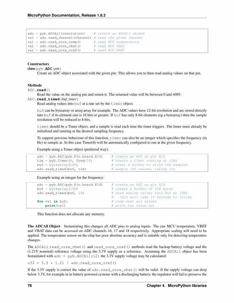
MicroPython Documentation, Release 1.8.3
adc = pyb.ADCAll(resolution) # create an ADCAll objectval = adc.read_channel(channel) # read the given channelval = adc.read_core_temp() # read MCU temperatureval = adc.read_core_vbat() # read MCU VBATval = adc.read_core_vref() # read MCU VREF
Constructorsclass pyb.ADC(pin)
Create an ADC object associated with the given pin. This allows you to then read analog values on that pin.
MethodsADC.read()
Read the value on the analog pin and return it. The returned value will be between 0 and 4095.ADC.read_timed(buf, timer)
Read analog values into buf at a rate set by the timer object.
buf can be bytearray or array.array for example. The ADC values have 12-bit resolution and are stored directlyinto buf if its element size is 16 bits or greater. If buf has only 8-bit elements (eg a bytearray) then the sampleresolution will be reduced to 8 bits.
timer should be a Timer object, and a sample is read each time the timer triggers. The timer must already beinitialised and running at the desired sampling frequency.
To support previous behaviour of this function, timer can also be an integer which specifies the frequency (inHz) to sample at. In this case Timer(6) will be automatically configured to run at the given frequency.
Example using a Timer object (preferred way):
adc = pyb.ADC(pyb.Pin.board.X19) # create an ADC on pin X19tim = pyb.Timer(6, freq=10) # create a timer running at 10Hzbuf = bytearray(100) # creat a buffer to store the samplesadc.read_timed(buf, tim) # sample 100 values, taking 10s
Example using an integer for the frequency:
adc = pyb.ADC(pyb.Pin.board.X19) # create an ADC on pin X19buf = bytearray(100) # create a buffer of 100 bytesadc.read_timed(buf, 10) # read analog values into buf at 10Hz
# this will take 10 seconds to finishfor val in buf: # loop over all values
print(val) # print the value out
This function does not allocate any memory.
The ADCAll Object Instantiating this changes all ADC pins to analog inputs. The raw MCU temperature, VREFand VBAT data can be accessed on ADC channels 16, 17 and 18 respectively. Appropriate scaling will need to beapplied. The temperature sensor on the chip has poor absolute accuracy and is suitable only for detecting temperaturechanges.
The ADCAll read_core_vbat() and read_core_vref() methods read the backup battery voltage and the(1.21V nominal) reference voltage using the 3.3V supply as a reference. Assuming the ADCAll object has beenInstantiated with adc = pyb.ADCAll(12) the 3.3V supply voltage may be calculated:
v33 = 3.3 * 1.21 / adc.read_core_vref()
If the 3.3V supply is correct the value of adc.read_core_vbat() will be valid. If the supply voltage can dropbelow 3.3V, for example in in battery powered systems with a discharging battery, the regulator will fail to preserve the
76 Chapter 4. MicroPython libraries
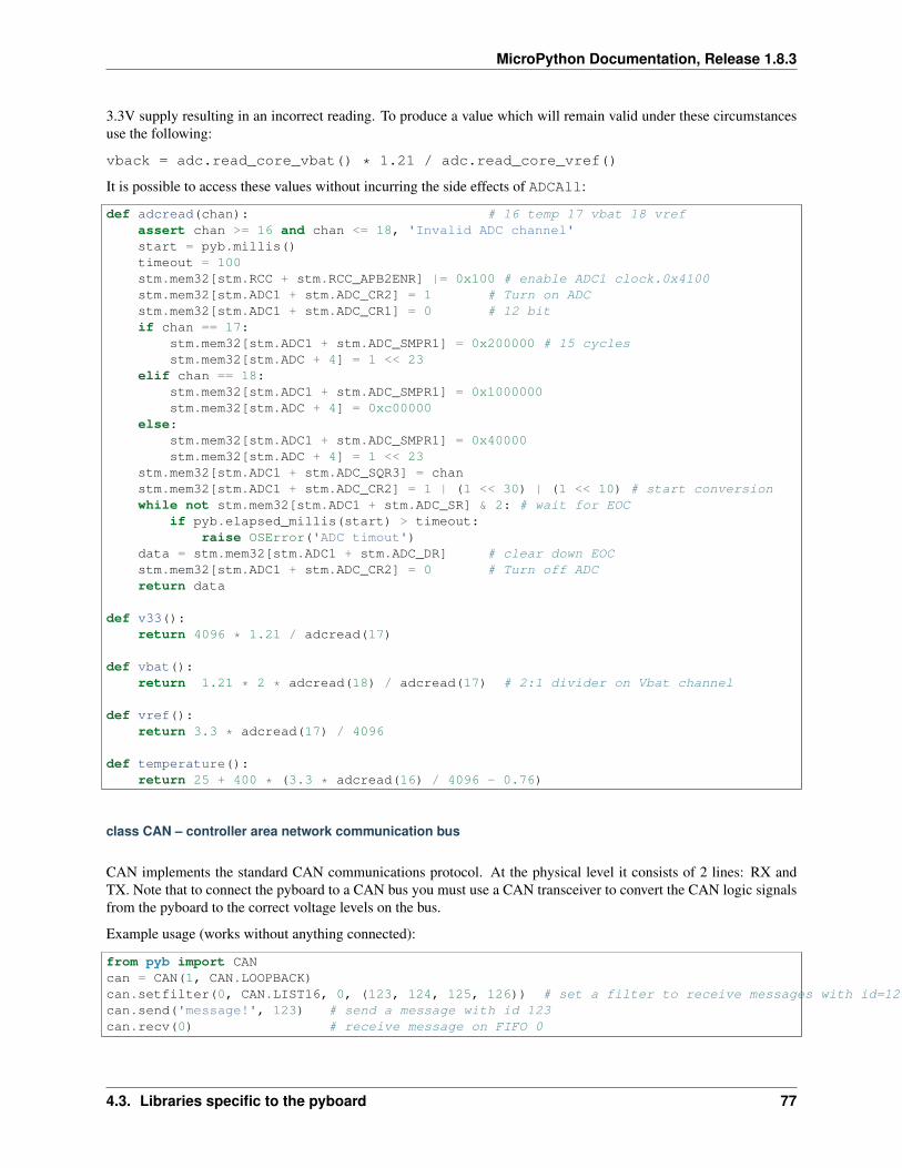
MicroPython Documentation, Release 1.8.3
3.3V supply resulting in an incorrect reading. To produce a value which will remain valid under these circumstancesuse the following:
vback = adc.read_core_vbat() * 1.21 / adc.read_core_vref()
It is possible to access these values without incurring the side effects of ADCAll:
def adcread(chan): # 16 temp 17 vbat 18 vrefassert chan >= 16 and chan <= 18, 'Invalid ADC channel'start = pyb.millis()timeout = 100stm.mem32[stm.RCC + stm.RCC_APB2ENR] |= 0x100 # enable ADC1 clock.0x4100stm.mem32[stm.ADC1 + stm.ADC_CR2] = 1 # Turn on ADCstm.mem32[stm.ADC1 + stm.ADC_CR1] = 0 # 12 bitif chan == 17:
stm.mem32[stm.ADC1 + stm.ADC_SMPR1] = 0x200000 # 15 cyclesstm.mem32[stm.ADC + 4] = 1 << 23
elif chan == 18:stm.mem32[stm.ADC1 + stm.ADC_SMPR1] = 0x1000000stm.mem32[stm.ADC + 4] = 0xc00000
else:stm.mem32[stm.ADC1 + stm.ADC_SMPR1] = 0x40000stm.mem32[stm.ADC + 4] = 1 << 23
stm.mem32[stm.ADC1 + stm.ADC_SQR3] = chanstm.mem32[stm.ADC1 + stm.ADC_CR2] = 1 | (1 << 30) | (1 << 10) # start conversionwhile not stm.mem32[stm.ADC1 + stm.ADC_SR] & 2: # wait for EOC
if pyb.elapsed_millis(start) > timeout:raise OSError('ADC timout')
data = stm.mem32[stm.ADC1 + stm.ADC_DR] # clear down EOCstm.mem32[stm.ADC1 + stm.ADC_CR2] = 0 # Turn off ADCreturn data
def v33():return 4096 * 1.21 / adcread(17)
def vbat():return 1.21 * 2 * adcread(18) / adcread(17) # 2:1 divider on Vbat channel
def vref():return 3.3 * adcread(17) / 4096
def temperature():return 25 + 400 * (3.3 * adcread(16) / 4096 - 0.76)
class CAN – controller area network communication bus
CAN implements the standard CAN communications protocol. At the physical level it consists of 2 lines: RX andTX. Note that to connect the pyboard to a CAN bus you must use a CAN transceiver to convert the CAN logic signalsfrom the pyboard to the correct voltage levels on the bus.
Example usage (works without anything connected):
from pyb import CANcan = CAN(1, CAN.LOOPBACK)can.setfilter(0, CAN.LIST16, 0, (123, 124, 125, 126)) # set a filter to receive messages with id=123, 124, 125 and 126can.send('message!', 123) # send a message with id 123can.recv(0) # receive message on FIFO 0
4.3. Libraries specific to the pyboard 77
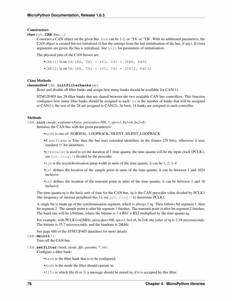
MicroPython Documentation, Release 1.8.3
Constructorsclass pyb.CAN(bus, ...)
Construct a CAN object on the given bus. bus can be 1-2, or ‘YA’ or ‘YB’. With no additional parameters, theCAN object is created but not initialised (it has the settings from the last initialisation of the bus, if any). If extraarguments are given, the bus is initialised. See init for parameters of initialisation.
The physical pins of the CAN busses are:
•CAN(1) is on YA: (RX, TX) = (Y3, Y4) = (PB8, PB9)
•CAN(2) is on YB: (RX, TX) = (Y5, Y6) = (PB12, PB13)
Class Methodsclassmethod CAN.initfilterbanks(nr)
Reset and disable all filter banks and assign how many banks should be available for CAN(1).
STM32F405 has 28 filter banks that are shared between the two available CAN bus controllers. This functionconfigures how many filter banks should be assigned to each. nr is the number of banks that will be assignedto CAN(1), the rest of the 28 are assigned to CAN(2). At boot, 14 banks are assigned to each controller.
MethodsCAN.init(mode, extframe=False, prescaler=100, *, sjw=1, bs1=6, bs2=8)
Initialise the CAN bus with the given parameters:
•mode is one of: NORMAL, LOOPBACK, SILENT, SILENT_LOOPBACK
•if extframe is True then the bus uses extended identifiers in the frames (29 bits); otherwise it usesstandard 11 bit identifiers
•prescaler is used to set the duration of 1 time quanta; the time quanta will be the input clock (PCLK1,see pyb.freq()) divided by the prescaler
•sjw is the resynchronisation jump width in units of the time quanta; it can be 1, 2, 3, 4
•bs1 defines the location of the sample point in units of the time quanta; it can be between 1 and 1024inclusive
•bs2 defines the location of the transmit point in units of the time quanta; it can be between 1 and 16inclusive
The time quanta tq is the basic unit of time for the CAN bus. tq is the CAN prescaler value divided by PCLK1(the frequency of internal peripheral bus 1); see pyb.freq() to determine PCLK1.
A single bit is made up of the synchronisation segment, which is always 1 tq. Then follows bit segment 1, thenbit segment 2. The sample point is after bit segment 1 finishes. The transmit point is after bit segment 2 finishes.The baud rate will be 1/bittime, where the bittime is 1 + BS1 + BS2 multiplied by the time quanta tq.
For example, with PCLK1=42MHz, prescaler=100, sjw=1, bs1=6, bs2=8, the value of tq is 2.38 microseconds.The bittime is 35.7 microseconds, and the baudrate is 28kHz.
See page 680 of the STM32F405 datasheet for more details.CAN.deinit()
Turn off the CAN bus.
CAN.setfilter(bank, mode, fifo, params, *, rtr)Configure a filter bank:
•bank is the filter bank that is to be configured.
•mode is the mode the filter should operate in.
•fifo is which fifo (0 or 1) a message should be stored in, if it is accepted by this filter.
78 Chapter 4. MicroPython libraries
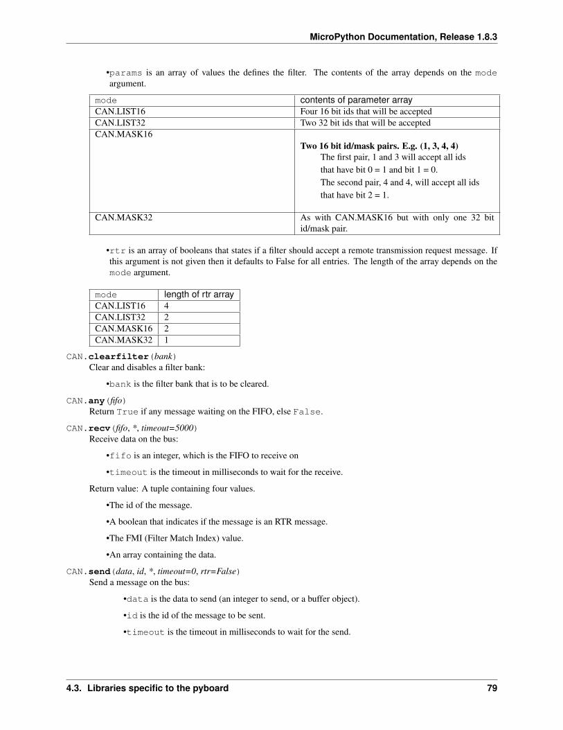
MicroPython Documentation, Release 1.8.3
•params is an array of values the defines the filter. The contents of the array depends on the modeargument.
mode contents of parameter arrayCAN.LIST16 Four 16 bit ids that will be acceptedCAN.LIST32 Two 32 bit ids that will be acceptedCAN.MASK16
Two 16 bit id/mask pairs. E.g. (1, 3, 4, 4)The first pair, 1 and 3 will accept all idsthat have bit 0 = 1 and bit 1 = 0.The second pair, 4 and 4, will accept all idsthat have bit 2 = 1.
CAN.MASK32 As with CAN.MASK16 but with only one 32 bitid/mask pair.
•rtr is an array of booleans that states if a filter should accept a remote transmission request message. Ifthis argument is not given then it defaults to False for all entries. The length of the array depends on themode argument.
mode length of rtr arrayCAN.LIST16 4CAN.LIST32 2CAN.MASK16 2CAN.MASK32 1
CAN.clearfilter(bank)Clear and disables a filter bank:
•bank is the filter bank that is to be cleared.
CAN.any(fifo)Return True if any message waiting on the FIFO, else False.
CAN.recv(fifo, *, timeout=5000)Receive data on the bus:
•fifo is an integer, which is the FIFO to receive on
•timeout is the timeout in milliseconds to wait for the receive.
Return value: A tuple containing four values.
•The id of the message.
•A boolean that indicates if the message is an RTR message.
•The FMI (Filter Match Index) value.
•An array containing the data.
CAN.send(data, id, *, timeout=0, rtr=False)Send a message on the bus:
•data is the data to send (an integer to send, or a buffer object).
•id is the id of the message to be sent.
•timeout is the timeout in milliseconds to wait for the send.
4.3. Libraries specific to the pyboard 79
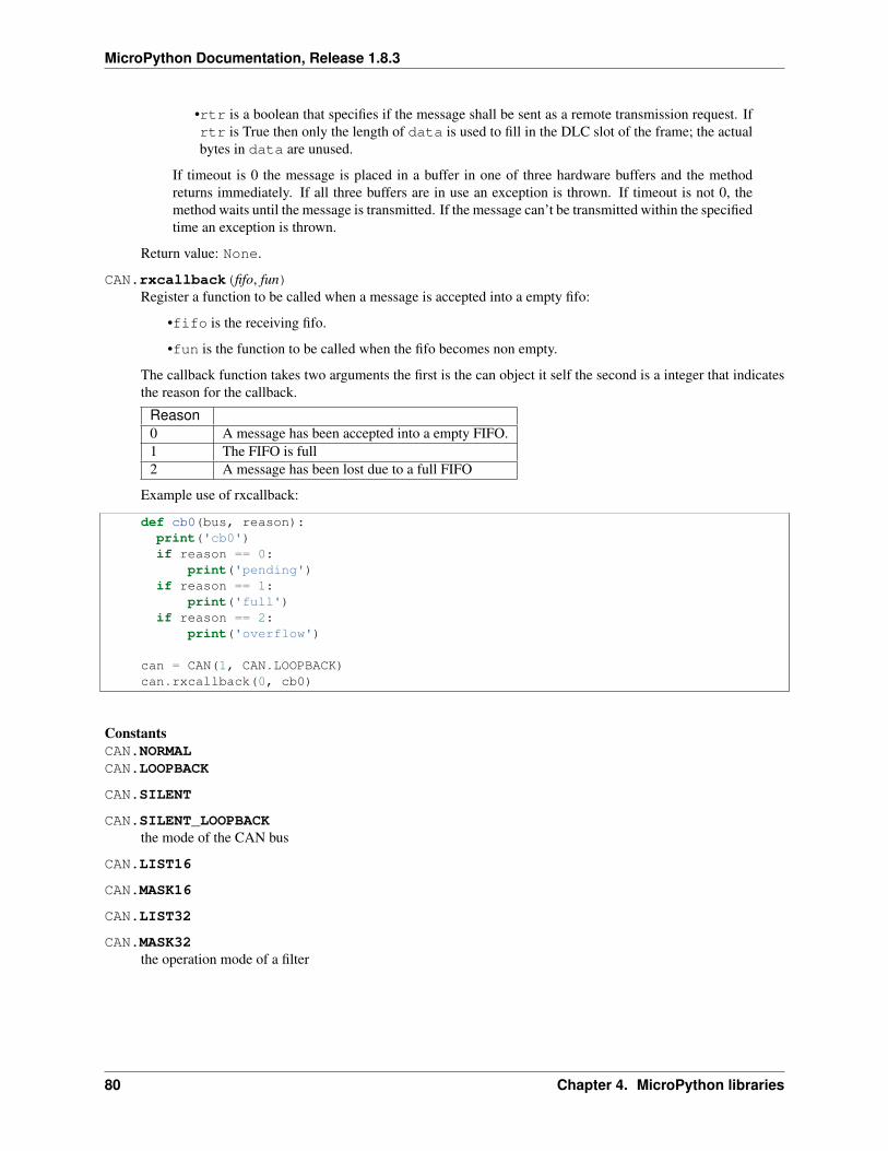
MicroPython Documentation, Release 1.8.3
•rtr is a boolean that specifies if the message shall be sent as a remote transmission request. Ifrtr is True then only the length of data is used to fill in the DLC slot of the frame; the actualbytes in data are unused.
If timeout is 0 the message is placed in a buffer in one of three hardware buffers and the methodreturns immediately. If all three buffers are in use an exception is thrown. If timeout is not 0, themethod waits until the message is transmitted. If the message can’t be transmitted within the specifiedtime an exception is thrown.
Return value: None.
CAN.rxcallback(fifo, fun)Register a function to be called when a message is accepted into a empty fifo:
•fifo is the receiving fifo.
•fun is the function to be called when the fifo becomes non empty.
The callback function takes two arguments the first is the can object it self the second is a integer that indicatesthe reason for the callback.
Reason0 A message has been accepted into a empty FIFO.1 The FIFO is full2 A message has been lost due to a full FIFO
Example use of rxcallback:
def cb0(bus, reason):print('cb0')if reason == 0:
print('pending')if reason == 1:
print('full')if reason == 2:
print('overflow')
can = CAN(1, CAN.LOOPBACK)can.rxcallback(0, cb0)
ConstantsCAN.NORMALCAN.LOOPBACK
CAN.SILENT
CAN.SILENT_LOOPBACKthe mode of the CAN bus
CAN.LIST16
CAN.MASK16
CAN.LIST32
CAN.MASK32the operation mode of a filter
80 Chapter 4. MicroPython libraries
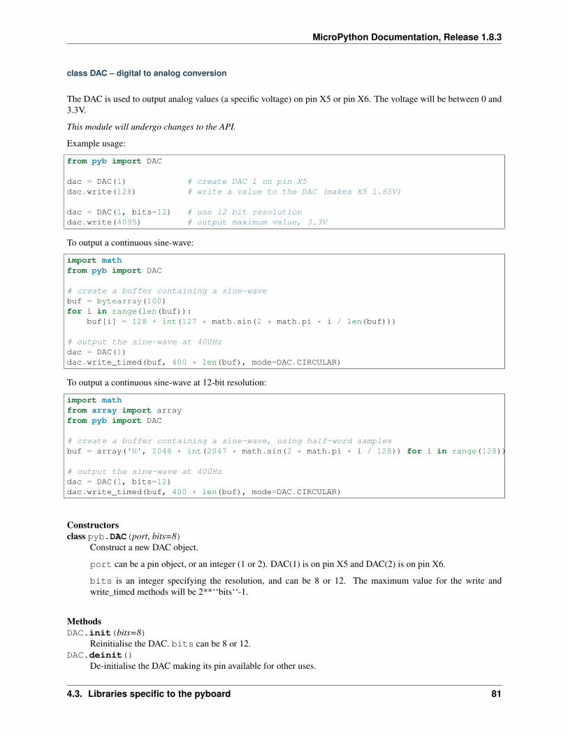
MicroPython Documentation, Release 1.8.3
class DAC – digital to analog conversion
The DAC is used to output analog values (a specific voltage) on pin X5 or pin X6. The voltage will be between 0 and3.3V.
This module will undergo changes to the API.
Example usage:
from pyb import DAC
dac = DAC(1) # create DAC 1 on pin X5dac.write(128) # write a value to the DAC (makes X5 1.65V)
dac = DAC(1, bits=12) # use 12 bit resolutiondac.write(4095) # output maximum value, 3.3V
To output a continuous sine-wave:
import mathfrom pyb import DAC
# create a buffer containing a sine-wavebuf = bytearray(100)for i in range(len(buf)):
buf[i] = 128 + int(127 * math.sin(2 * math.pi * i / len(buf)))
# output the sine-wave at 400Hzdac = DAC(1)dac.write_timed(buf, 400 * len(buf), mode=DAC.CIRCULAR)
To output a continuous sine-wave at 12-bit resolution:
import mathfrom array import arrayfrom pyb import DAC
# create a buffer containing a sine-wave, using half-word samplesbuf = array('H', 2048 + int(2047 * math.sin(2 * math.pi * i / 128)) for i in range(128))
# output the sine-wave at 400Hzdac = DAC(1, bits=12)dac.write_timed(buf, 400 * len(buf), mode=DAC.CIRCULAR)
Constructorsclass pyb.DAC(port, bits=8)
Construct a new DAC object.
port can be a pin object, or an integer (1 or 2). DAC(1) is on pin X5 and DAC(2) is on pin X6.
bits is an integer specifying the resolution, and can be 8 or 12. The maximum value for the write andwrite_timed methods will be 2**‘‘bits‘‘-1.
MethodsDAC.init(bits=8)
Reinitialise the DAC. bits can be 8 or 12.DAC.deinit()
De-initialise the DAC making its pin available for other uses.
4.3. Libraries specific to the pyboard 81
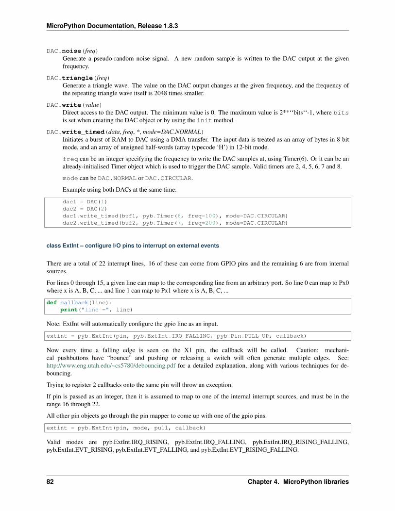
MicroPython Documentation, Release 1.8.3
DAC.noise(freq)Generate a pseudo-random noise signal. A new random sample is written to the DAC output at the givenfrequency.
DAC.triangle(freq)Generate a triangle wave. The value on the DAC output changes at the given frequency, and the frequency ofthe repeating triangle wave itself is 2048 times smaller.
DAC.write(value)Direct access to the DAC output. The minimum value is 0. The maximum value is 2**‘‘bits‘‘-1, where bitsis set when creating the DAC object or by using the init method.
DAC.write_timed(data, freq, *, mode=DAC.NORMAL)Initiates a burst of RAM to DAC using a DMA transfer. The input data is treated as an array of bytes in 8-bitmode, and an array of unsigned half-words (array typecode ‘H’) in 12-bit mode.
freq can be an integer specifying the frequency to write the DAC samples at, using Timer(6). Or it can be analready-initialised Timer object which is used to trigger the DAC sample. Valid timers are 2, 4, 5, 6, 7 and 8.
mode can be DAC.NORMAL or DAC.CIRCULAR.
Example using both DACs at the same time:
dac1 = DAC(1)dac2 = DAC(2)dac1.write_timed(buf1, pyb.Timer(6, freq=100), mode=DAC.CIRCULAR)dac2.write_timed(buf2, pyb.Timer(7, freq=200), mode=DAC.CIRCULAR)
class ExtInt – configure I/O pins to interrupt on external events
There are a total of 22 interrupt lines. 16 of these can come from GPIO pins and the remaining 6 are from internalsources.
For lines 0 through 15, a given line can map to the corresponding line from an arbitrary port. So line 0 can map to Px0where x is A, B, C, ... and line 1 can map to Px1 where x is A, B, C, ...
def callback(line):print("line =", line)
Note: ExtInt will automatically configure the gpio line as an input.
extint = pyb.ExtInt(pin, pyb.ExtInt.IRQ_FALLING, pyb.Pin.PULL_UP, callback)
Now every time a falling edge is seen on the X1 pin, the callback will be called. Caution: mechani-cal pushbuttons have “bounce” and pushing or releasing a switch will often generate multiple edges. See:http://www.eng.utah.edu/~cs5780/debouncing.pdf for a detailed explanation, along with various techniques for de-bouncing.
Trying to register 2 callbacks onto the same pin will throw an exception.
If pin is passed as an integer, then it is assumed to map to one of the internal interrupt sources, and must be in therange 16 through 22.
All other pin objects go through the pin mapper to come up with one of the gpio pins.
extint = pyb.ExtInt(pin, mode, pull, callback)
Valid modes are pyb.ExtInt.IRQ_RISING, pyb.ExtInt.IRQ_FALLING, pyb.ExtInt.IRQ_RISING_FALLING,pyb.ExtInt.EVT_RISING, pyb.ExtInt.EVT_FALLING, and pyb.ExtInt.EVT_RISING_FALLING.
82 Chapter 4. MicroPython libraries
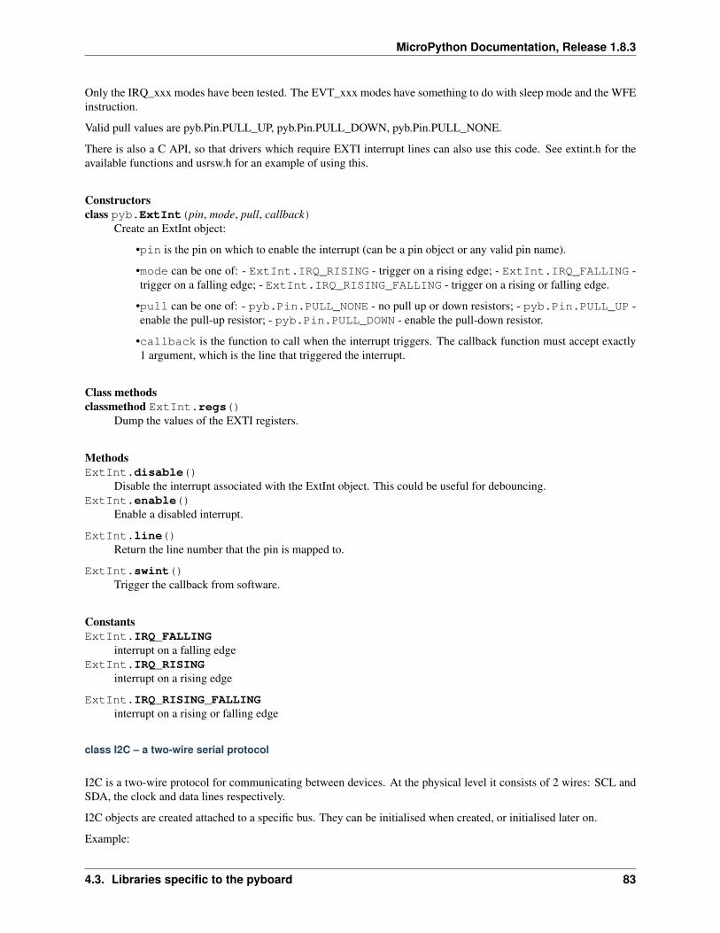
MicroPython Documentation, Release 1.8.3
Only the IRQ_xxx modes have been tested. The EVT_xxx modes have something to do with sleep mode and the WFEinstruction.
Valid pull values are pyb.Pin.PULL_UP, pyb.Pin.PULL_DOWN, pyb.Pin.PULL_NONE.
There is also a C API, so that drivers which require EXTI interrupt lines can also use this code. See extint.h for theavailable functions and usrsw.h for an example of using this.
Constructorsclass pyb.ExtInt(pin, mode, pull, callback)
Create an ExtInt object:
•pin is the pin on which to enable the interrupt (can be a pin object or any valid pin name).
•mode can be one of: - ExtInt.IRQ_RISING - trigger on a rising edge; - ExtInt.IRQ_FALLING -trigger on a falling edge; - ExtInt.IRQ_RISING_FALLING - trigger on a rising or falling edge.
•pull can be one of: - pyb.Pin.PULL_NONE - no pull up or down resistors; - pyb.Pin.PULL_UP -enable the pull-up resistor; - pyb.Pin.PULL_DOWN - enable the pull-down resistor.
•callback is the function to call when the interrupt triggers. The callback function must accept exactly1 argument, which is the line that triggered the interrupt.
Class methodsclassmethod ExtInt.regs()
Dump the values of the EXTI registers.
MethodsExtInt.disable()
Disable the interrupt associated with the ExtInt object. This could be useful for debouncing.ExtInt.enable()
Enable a disabled interrupt.
ExtInt.line()Return the line number that the pin is mapped to.
ExtInt.swint()Trigger the callback from software.
ConstantsExtInt.IRQ_FALLING
interrupt on a falling edgeExtInt.IRQ_RISING
interrupt on a rising edge
ExtInt.IRQ_RISING_FALLINGinterrupt on a rising or falling edge
class I2C – a two-wire serial protocol
I2C is a two-wire protocol for communicating between devices. At the physical level it consists of 2 wires: SCL andSDA, the clock and data lines respectively.
I2C objects are created attached to a specific bus. They can be initialised when created, or initialised later on.
Example:
4.3. Libraries specific to the pyboard 83
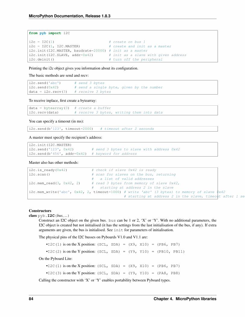
MicroPython Documentation, Release 1.8.3
from pyb import I2C
i2c = I2C(1) # create on bus 1i2c = I2C(1, I2C.MASTER) # create and init as a masteri2c.init(I2C.MASTER, baudrate=20000) # init as a masteri2c.init(I2C.SLAVE, addr=0x42) # init as a slave with given addressi2c.deinit() # turn off the peripheral
Printing the i2c object gives you information about its configuration.
The basic methods are send and recv:
i2c.send('abc') # send 3 bytesi2c.send(0x42) # send a single byte, given by the numberdata = i2c.recv(3) # receive 3 bytes
To receive inplace, first create a bytearray:
data = bytearray(3) # create a bufferi2c.recv(data) # receive 3 bytes, writing them into data
You can specify a timeout (in ms):
i2c.send(b'123', timeout=2000) # timeout after 2 seconds
A master must specify the recipient’s address:
i2c.init(I2C.MASTER)i2c.send('123', 0x42) # send 3 bytes to slave with address 0x42i2c.send(b'456', addr=0x42) # keyword for address
Master also has other methods:
i2c.is_ready(0x42) # check if slave 0x42 is readyi2c.scan() # scan for slaves on the bus, returning
# a list of valid addressesi2c.mem_read(3, 0x42, 2) # read 3 bytes from memory of slave 0x42,
# starting at address 2 in the slavei2c.mem_write('abc', 0x42, 2, timeout=1000) # write 'abc' (3 bytes) to memory of slave 0x42
# starting at address 2 in the slave, timeout after 1 second
Constructorsclass pyb.I2C(bus, ...)
Construct an I2C object on the given bus. bus can be 1 or 2, ‘X’ or ‘Y’. With no additional parameters, theI2C object is created but not initialised (it has the settings from the last initialisation of the bus, if any). If extraarguments are given, the bus is initialised. See init for parameters of initialisation.
The physical pins of the I2C busses on Pyboards V1.0 and V1.1 are:
•I2C(1) is on the X position: (SCL, SDA) = (X9, X10) = (PB6, PB7)
•I2C(2) is on the Y position: (SCL, SDA) = (Y9, Y10) = (PB10, PB11)
On the Pyboard Lite:
•I2C(1) is on the X position: (SCL, SDA) = (X9, X10) = (PB6, PB7)
•I2C(3) is on the Y position: (SCL, SDA) = (Y9, Y10) = (PA8, PB8)
Calling the constructor with ‘X’ or ‘Y’ enables portability between Pyboard types.
84 Chapter 4. MicroPython libraries
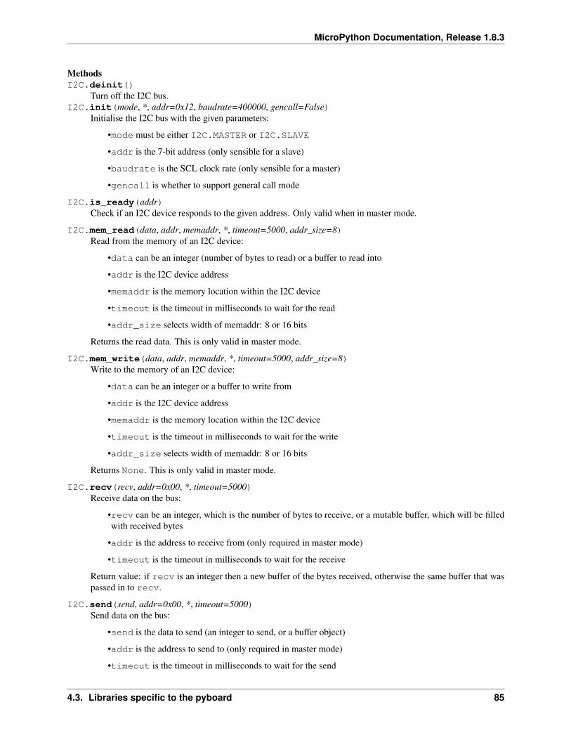
MicroPython Documentation, Release 1.8.3
MethodsI2C.deinit()
Turn off the I2C bus.I2C.init(mode, *, addr=0x12, baudrate=400000, gencall=False)
Initialise the I2C bus with the given parameters:
•mode must be either I2C.MASTER or I2C.SLAVE
•addr is the 7-bit address (only sensible for a slave)
•baudrate is the SCL clock rate (only sensible for a master)
•gencall is whether to support general call mode
I2C.is_ready(addr)Check if an I2C device responds to the given address. Only valid when in master mode.
I2C.mem_read(data, addr, memaddr, *, timeout=5000, addr_size=8)Read from the memory of an I2C device:
•data can be an integer (number of bytes to read) or a buffer to read into
•addr is the I2C device address
•memaddr is the memory location within the I2C device
•timeout is the timeout in milliseconds to wait for the read
•addr_size selects width of memaddr: 8 or 16 bits
Returns the read data. This is only valid in master mode.
I2C.mem_write(data, addr, memaddr, *, timeout=5000, addr_size=8)Write to the memory of an I2C device:
•data can be an integer or a buffer to write from
•addr is the I2C device address
•memaddr is the memory location within the I2C device
•timeout is the timeout in milliseconds to wait for the write
•addr_size selects width of memaddr: 8 or 16 bits
Returns None. This is only valid in master mode.
I2C.recv(recv, addr=0x00, *, timeout=5000)Receive data on the bus:
•recv can be an integer, which is the number of bytes to receive, or a mutable buffer, which will be filledwith received bytes
•addr is the address to receive from (only required in master mode)
•timeout is the timeout in milliseconds to wait for the receive
Return value: if recv is an integer then a new buffer of the bytes received, otherwise the same buffer that waspassed in to recv.
I2C.send(send, addr=0x00, *, timeout=5000)Send data on the bus:
•send is the data to send (an integer to send, or a buffer object)
•addr is the address to send to (only required in master mode)
•timeout is the timeout in milliseconds to wait for the send
4.3. Libraries specific to the pyboard 85
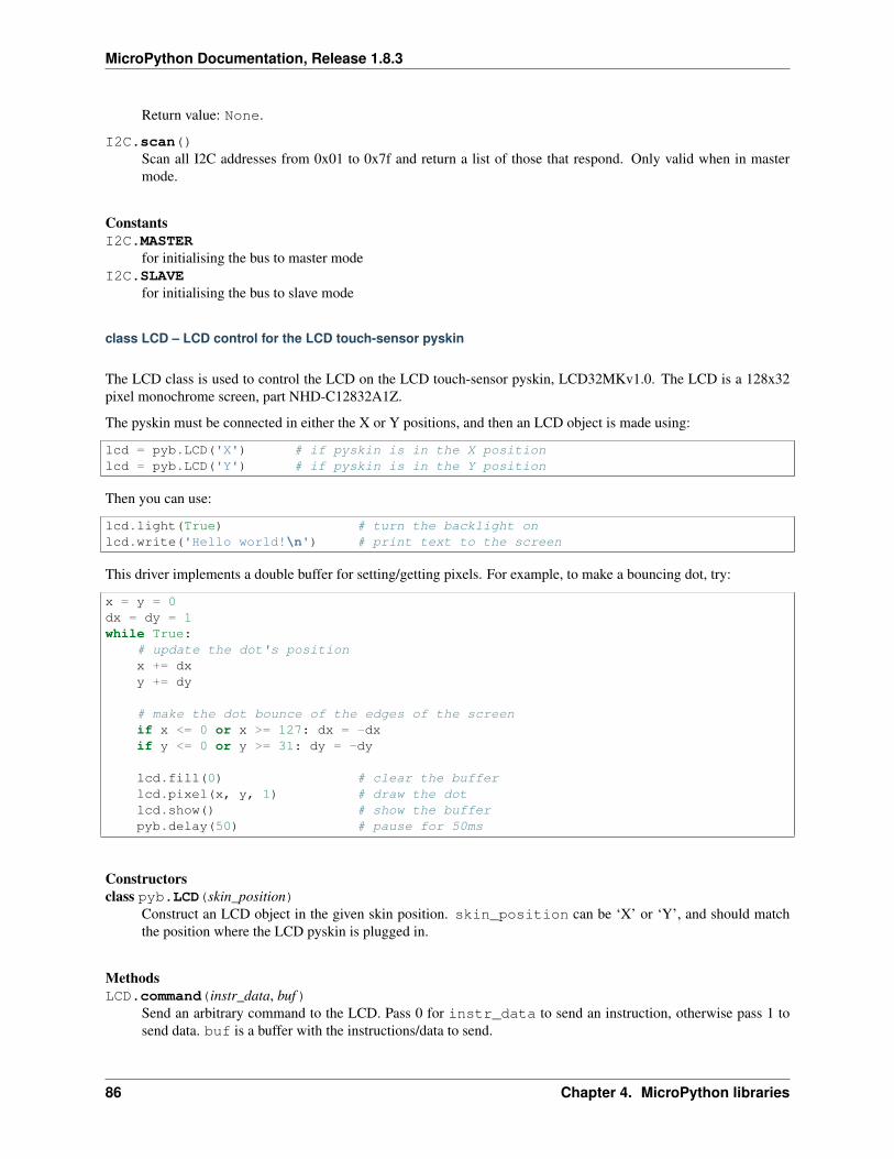
MicroPython Documentation, Release 1.8.3
Return value: None.
I2C.scan()Scan all I2C addresses from 0x01 to 0x7f and return a list of those that respond. Only valid when in mastermode.
ConstantsI2C.MASTER
for initialising the bus to master modeI2C.SLAVE
for initialising the bus to slave mode
class LCD – LCD control for the LCD touch-sensor pyskin
The LCD class is used to control the LCD on the LCD touch-sensor pyskin, LCD32MKv1.0. The LCD is a 128x32pixel monochrome screen, part NHD-C12832A1Z.
The pyskin must be connected in either the X or Y positions, and then an LCD object is made using:
lcd = pyb.LCD('X') # if pyskin is in the X positionlcd = pyb.LCD('Y') # if pyskin is in the Y position
Then you can use:
lcd.light(True) # turn the backlight onlcd.write('Hello world!\n') # print text to the screen
This driver implements a double buffer for setting/getting pixels. For example, to make a bouncing dot, try:
x = y = 0dx = dy = 1while True:
# update the dot's positionx += dxy += dy
# make the dot bounce of the edges of the screenif x <= 0 or x >= 127: dx = -dxif y <= 0 or y >= 31: dy = -dy
lcd.fill(0) # clear the bufferlcd.pixel(x, y, 1) # draw the dotlcd.show() # show the bufferpyb.delay(50) # pause for 50ms
Constructorsclass pyb.LCD(skin_position)
Construct an LCD object in the given skin position. skin_position can be ‘X’ or ‘Y’, and should matchthe position where the LCD pyskin is plugged in.
MethodsLCD.command(instr_data, buf)
Send an arbitrary command to the LCD. Pass 0 for instr_data to send an instruction, otherwise pass 1 tosend data. buf is a buffer with the instructions/data to send.
86 Chapter 4. MicroPython libraries
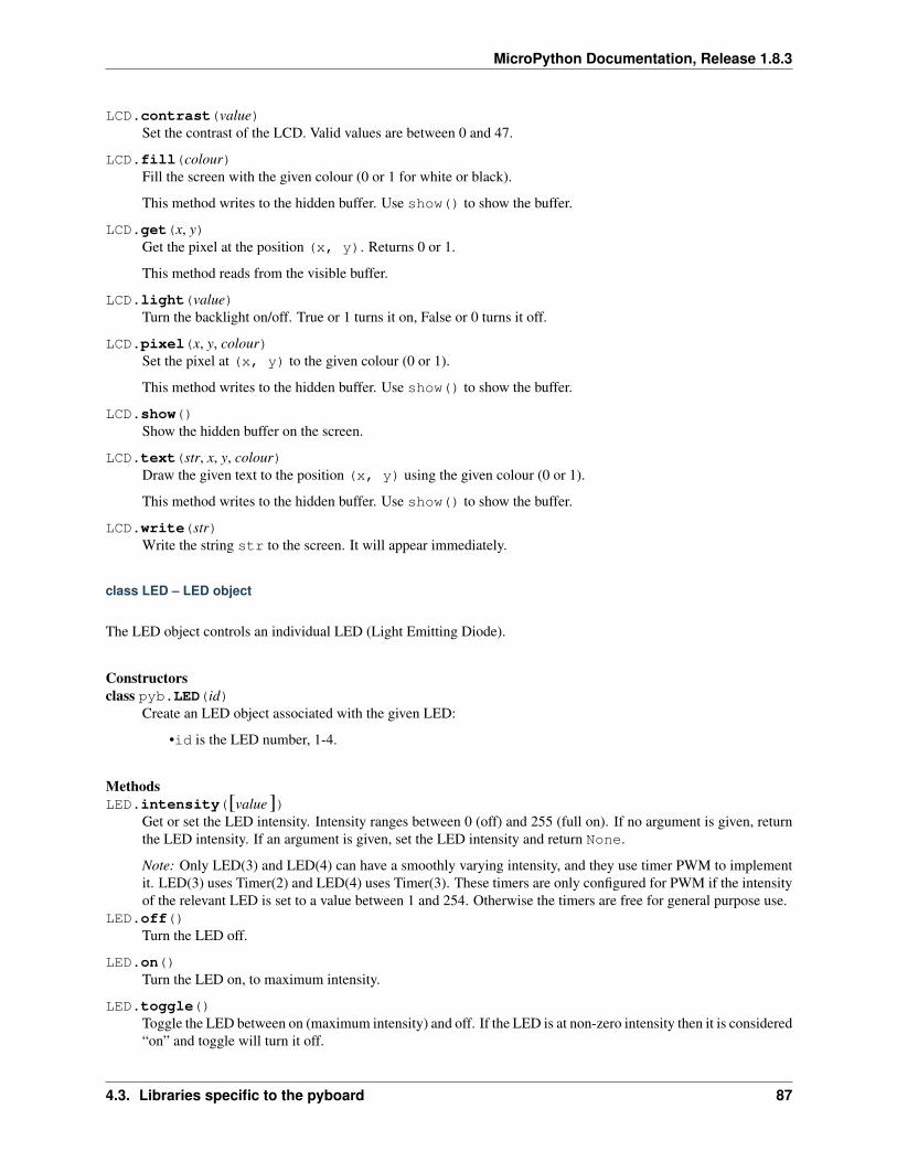
MicroPython Documentation, Release 1.8.3
LCD.contrast(value)Set the contrast of the LCD. Valid values are between 0 and 47.
LCD.fill(colour)Fill the screen with the given colour (0 or 1 for white or black).
This method writes to the hidden buffer. Use show() to show the buffer.
LCD.get(x, y)Get the pixel at the position (x, y). Returns 0 or 1.
This method reads from the visible buffer.
LCD.light(value)Turn the backlight on/off. True or 1 turns it on, False or 0 turns it off.
LCD.pixel(x, y, colour)Set the pixel at (x, y) to the given colour (0 or 1).
This method writes to the hidden buffer. Use show() to show the buffer.
LCD.show()Show the hidden buffer on the screen.
LCD.text(str, x, y, colour)Draw the given text to the position (x, y) using the given colour (0 or 1).
This method writes to the hidden buffer. Use show() to show the buffer.
LCD.write(str)Write the string str to the screen. It will appear immediately.
class LED – LED object
The LED object controls an individual LED (Light Emitting Diode).
Constructorsclass pyb.LED(id)
Create an LED object associated with the given LED:
•id is the LED number, 1-4.
MethodsLED.intensity([value])
Get or set the LED intensity. Intensity ranges between 0 (off) and 255 (full on). If no argument is given, returnthe LED intensity. If an argument is given, set the LED intensity and return None.
Note: Only LED(3) and LED(4) can have a smoothly varying intensity, and they use timer PWM to implementit. LED(3) uses Timer(2) and LED(4) uses Timer(3). These timers are only configured for PWM if the intensityof the relevant LED is set to a value between 1 and 254. Otherwise the timers are free for general purpose use.
LED.off()Turn the LED off.
LED.on()Turn the LED on, to maximum intensity.
LED.toggle()Toggle the LED between on (maximum intensity) and off. If the LED is at non-zero intensity then it is considered“on” and toggle will turn it off.
4.3. Libraries specific to the pyboard 87
MicroPython Documentation, Release 1.8.3
class Pin – control I/O pins
A pin is the basic object to control I/O pins. It has methods to set the mode of the pin (input, output, etc) and methodsto get and set the digital logic level. For analog control of a pin, see the ADC class.
Usage Model:
All Board Pins are predefined as pyb.Pin.board.Name:
x1_pin = pyb.Pin.board.X1
g = pyb.Pin(pyb.Pin.board.X1, pyb.Pin.IN)
CPU pins which correspond to the board pins are available as pyb.cpu.Name. For the CPU pins, the names are theport letter followed by the pin number. On the PYBv1.0, pyb.Pin.board.X1 and pyb.Pin.cpu.B6 are thesame pin.
You can also use strings:
g = pyb.Pin('X1', pyb.Pin.OUT_PP)
Users can add their own names:
MyMapperDict = { 'LeftMotorDir' : pyb.Pin.cpu.C12 }pyb.Pin.dict(MyMapperDict)g = pyb.Pin("LeftMotorDir", pyb.Pin.OUT_OD)
and can query mappings:
pin = pyb.Pin("LeftMotorDir")
Users can also add their own mapping function:
def MyMapper(pin_name):if pin_name == "LeftMotorDir":
return pyb.Pin.cpu.A0
pyb.Pin.mapper(MyMapper)
So, if you were to call: pyb.Pin("LeftMotorDir", pyb.Pin.OUT_PP) then "LeftMotorDir" is passeddirectly to the mapper function.
To summarise, the following order determines how things get mapped into an ordinal pin number:
1. Directly specify a pin object
2. User supplied mapping function
3. User supplied mapping (object must be usable as a dictionary key)
4. Supply a string which matches a board pin
5. Supply a string which matches a CPU port/pin
You can set pyb.Pin.debug(True) to get some debug information about how a particular object gets mapped toa pin.
When a pin has the Pin.PULL_UP or Pin.PULL_DOWN pull-mode enabled, that pin has an effective 40k Ohmresistor pulling it to 3V3 or GND respectively (except pin Y5 which has 11k Ohm resistors).
Now every time a falling edge is seen on the gpio pin, the callback will be executed. Caution: mechani-cal push buttons have “bounce” and pushing or releasing a switch will often generate multiple edges. See:
88 Chapter 4. MicroPython libraries
MicroPython Documentation, Release 1.8.3
http://www.eng.utah.edu/~cs5780/debouncing.pdf for a detailed explanation, along with various techniques for de-bouncing.
All pin objects go through the pin mapper to come up with one of the gpio pins.
Constructorsclass pyb.Pin(id, ...)
Create a new Pin object associated with the id. If additional arguments are given, they are used to initialise thepin. See pin.init().
Class methodsclassmethod Pin.debug([state])
Get or set the debugging state (True or False for on or off).classmethod Pin.dict([dict ])
Get or set the pin mapper dictionary.
classmethod Pin.mapper([fun])Get or set the pin mapper function.
MethodsPin.init(mode, pull=Pin.PULL_NONE, af=-1)
Initialise the pin:
•mode can be one of:
–Pin.IN - configure the pin for input;
–Pin.OUT_PP - configure the pin for output, with push-pull control;
–Pin.OUT_OD - configure the pin for output, with open-drain control;
–Pin.AF_PP - configure the pin for alternate function, pull-pull;
–Pin.AF_OD - configure the pin for alternate function, open-drain;
–Pin.ANALOG - configure the pin for analog.
•pull can be one of:
–Pin.PULL_NONE - no pull up or down resistors;
–Pin.PULL_UP - enable the pull-up resistor;
–Pin.PULL_DOWN - enable the pull-down resistor.
•when mode is Pin.AF_PP or Pin.AF_OD, then af can be the index or name of one of the alternatefunctions associated with a pin.
Returns: None.Pin.value([value])
Get or set the digital logic level of the pin:
•With no argument, return 0 or 1 depending on the logic level of the pin.
•With value given, set the logic level of the pin. value can be anything that converts to a boolean. If itconverts to True, the pin is set high, otherwise it is set low.
Pin.__str__()Return a string describing the pin object.
4.3. Libraries specific to the pyboard 89
MicroPython Documentation, Release 1.8.3
Pin.af()Returns the currently configured alternate-function of the pin. The integer returned will match one of the allowedconstants for the af argument to the init function.
Pin.af_list()Returns an array of alternate functions available for this pin.
Pin.gpio()Returns the base address of the GPIO block associated with this pin.
Pin.mode()Returns the currently configured mode of the pin. The integer returned will match one of the allowed constantsfor the mode argument to the init function.
Pin.name()Get the pin name.
Pin.names()Returns the cpu and board names for this pin.
Pin.pin()Get the pin number.
Pin.port()Get the pin port.
Pin.pull()Returns the currently configured pull of the pin. The integer returned will match one of the allowed constantsfor the pull argument to the init function.
ConstantsPin.AF_OD
initialise the pin to alternate-function mode with an open-drain drivePin.AF_PP
initialise the pin to alternate-function mode with a push-pull drive
Pin.ANALOGinitialise the pin to analog mode
Pin.INinitialise the pin to input mode
Pin.OUT_ODinitialise the pin to output mode with an open-drain drive
Pin.OUT_PPinitialise the pin to output mode with a push-pull drive
Pin.PULL_DOWNenable the pull-down resistor on the pin
Pin.PULL_NONEdon’t enable any pull up or down resistors on the pin
Pin.PULL_UPenable the pull-up resistor on the pin
90 Chapter 4. MicroPython libraries
MicroPython Documentation, Release 1.8.3
class PinAF – Pin Alternate Functions
A Pin represents a physical pin on the microprocessor. Each pin can have a variety of functions (GPIO, I2C SDA, etc).Each PinAF object represents a particular function for a pin.
Usage Model:
x3 = pyb.Pin.board.X3x3_af = x3.af_list()
x3_af will now contain an array of PinAF objects which are available on pin X3.
For the pyboard, x3_af would contain: [Pin.AF1_TIM2, Pin.AF2_TIM5, Pin.AF3_TIM9, Pin.AF7_USART2]
Normally, each peripheral would configure the af automatically, but sometimes the same function is available onmultiple pins, and having more control is desired.
To configure X3 to expose TIM2_CH3, you could use:
pin = pyb.Pin(pyb.Pin.board.X3, mode=pyb.Pin.AF_PP, af=pyb.Pin.AF1_TIM2)
or:
pin = pyb.Pin(pyb.Pin.board.X3, mode=pyb.Pin.AF_PP, af=1)
Methodspinaf.__str__()
Return a string describing the alternate function.pinaf.index()
Return the alternate function index.
pinaf.name()Return the name of the alternate function.
pinaf.reg()Return the base register associated with the peripheral assigned to this alternate function. For example, if thealternate function were TIM2_CH3 this would return stm.TIM2
class RTC – real time clock
The RTC is and independent clock that keeps track of the date and time.
Example usage:
rtc = pyb.RTC()rtc.datetime((2014, 5, 1, 4, 13, 0, 0, 0))print(rtc.datetime())
Constructorsclass pyb.RTC
Create an RTC object.
Methods
4.3. Libraries specific to the pyboard 91
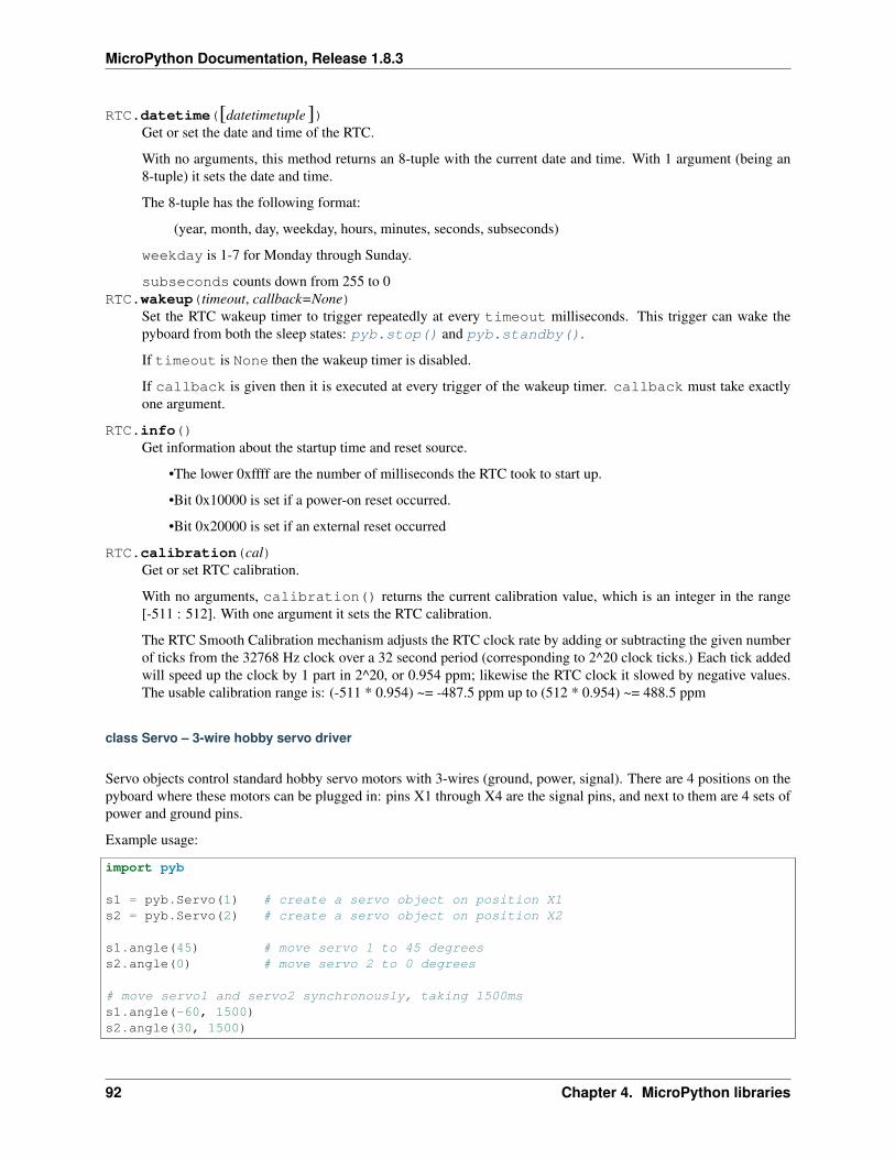
MicroPython Documentation, Release 1.8.3
RTC.datetime([datetimetuple])Get or set the date and time of the RTC.
With no arguments, this method returns an 8-tuple with the current date and time. With 1 argument (being an8-tuple) it sets the date and time.
The 8-tuple has the following format:
(year, month, day, weekday, hours, minutes, seconds, subseconds)
weekday is 1-7 for Monday through Sunday.
subseconds counts down from 255 to 0RTC.wakeup(timeout, callback=None)
Set the RTC wakeup timer to trigger repeatedly at every timeout milliseconds. This trigger can wake thepyboard from both the sleep states: pyb.stop() and pyb.standby().
If timeout is None then the wakeup timer is disabled.
If callback is given then it is executed at every trigger of the wakeup timer. callback must take exactlyone argument.
RTC.info()Get information about the startup time and reset source.
•The lower 0xffff are the number of milliseconds the RTC took to start up.
•Bit 0x10000 is set if a power-on reset occurred.
•Bit 0x20000 is set if an external reset occurred
RTC.calibration(cal)Get or set RTC calibration.
With no arguments, calibration() returns the current calibration value, which is an integer in the range[-511 : 512]. With one argument it sets the RTC calibration.
The RTC Smooth Calibration mechanism adjusts the RTC clock rate by adding or subtracting the given numberof ticks from the 32768 Hz clock over a 32 second period (corresponding to 2^20 clock ticks.) Each tick addedwill speed up the clock by 1 part in 2^20, or 0.954 ppm; likewise the RTC clock it slowed by negative values.The usable calibration range is: (-511 * 0.954) ~= -487.5 ppm up to (512 * 0.954) ~= 488.5 ppm
class Servo – 3-wire hobby servo driver
Servo objects control standard hobby servo motors with 3-wires (ground, power, signal). There are 4 positions on thepyboard where these motors can be plugged in: pins X1 through X4 are the signal pins, and next to them are 4 sets ofpower and ground pins.
Example usage:
import pyb
s1 = pyb.Servo(1) # create a servo object on position X1s2 = pyb.Servo(2) # create a servo object on position X2
s1.angle(45) # move servo 1 to 45 degreess2.angle(0) # move servo 2 to 0 degrees
# move servo1 and servo2 synchronously, taking 1500mss1.angle(-60, 1500)s2.angle(30, 1500)
92 Chapter 4. MicroPython libraries
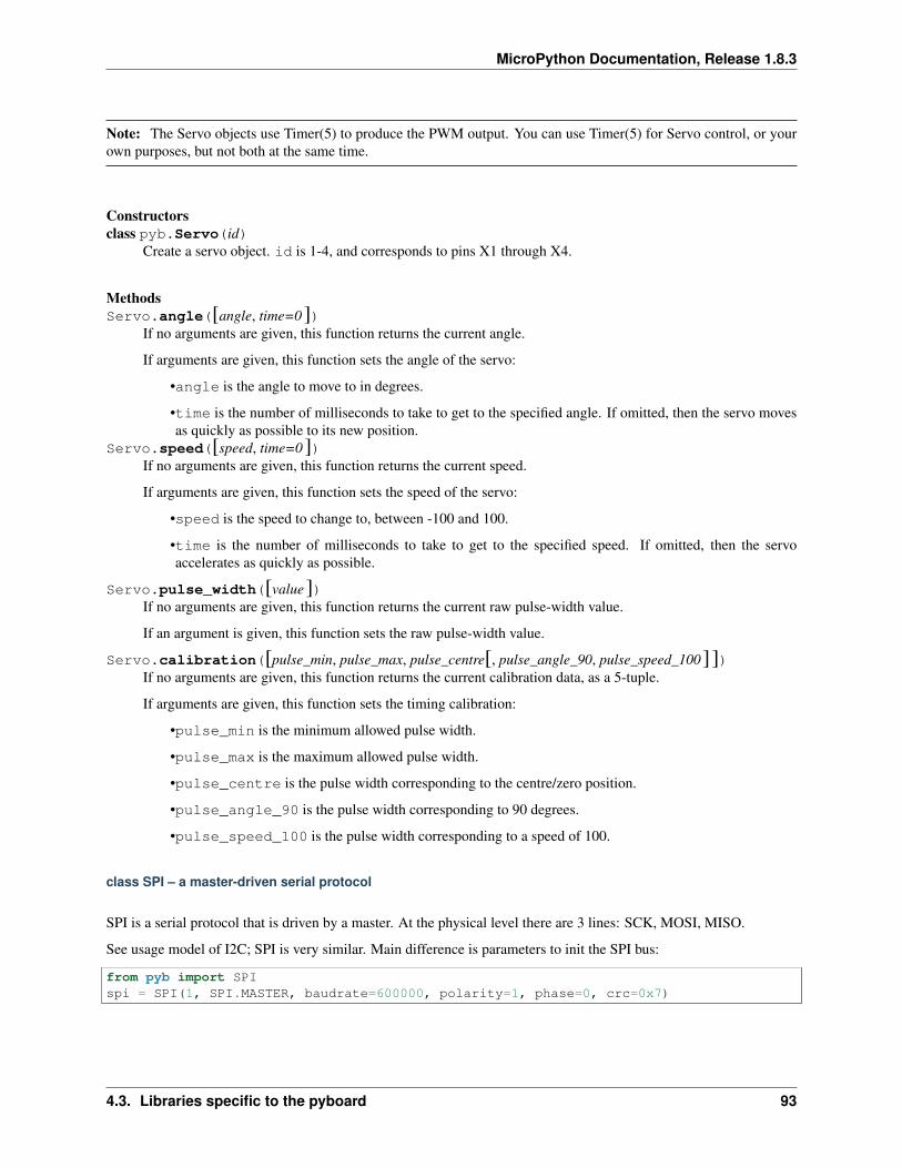
MicroPython Documentation, Release 1.8.3
Note: The Servo objects use Timer(5) to produce the PWM output. You can use Timer(5) for Servo control, or yourown purposes, but not both at the same time.
Constructorsclass pyb.Servo(id)
Create a servo object. id is 1-4, and corresponds to pins X1 through X4.
MethodsServo.angle([angle, time=0])
If no arguments are given, this function returns the current angle.
If arguments are given, this function sets the angle of the servo:
•angle is the angle to move to in degrees.
•time is the number of milliseconds to take to get to the specified angle. If omitted, then the servo movesas quickly as possible to its new position.
Servo.speed([speed, time=0])If no arguments are given, this function returns the current speed.
If arguments are given, this function sets the speed of the servo:
•speed is the speed to change to, between -100 and 100.
•time is the number of milliseconds to take to get to the specified speed. If omitted, then the servoaccelerates as quickly as possible.
Servo.pulse_width([value])If no arguments are given, this function returns the current raw pulse-width value.
If an argument is given, this function sets the raw pulse-width value.
Servo.calibration([pulse_min, pulse_max, pulse_centre[, pulse_angle_90, pulse_speed_100]])If no arguments are given, this function returns the current calibration data, as a 5-tuple.
If arguments are given, this function sets the timing calibration:
•pulse_min is the minimum allowed pulse width.
•pulse_max is the maximum allowed pulse width.
•pulse_centre is the pulse width corresponding to the centre/zero position.
•pulse_angle_90 is the pulse width corresponding to 90 degrees.
•pulse_speed_100 is the pulse width corresponding to a speed of 100.
class SPI – a master-driven serial protocol
SPI is a serial protocol that is driven by a master. At the physical level there are 3 lines: SCK, MOSI, MISO.
See usage model of I2C; SPI is very similar. Main difference is parameters to init the SPI bus:
from pyb import SPIspi = SPI(1, SPI.MASTER, baudrate=600000, polarity=1, phase=0, crc=0x7)
4.3. Libraries specific to the pyboard 93
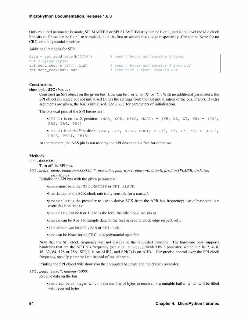
MicroPython Documentation, Release 1.8.3
Only required parameter is mode, SPI.MASTER or SPI.SLAVE. Polarity can be 0 or 1, and is the level the idle clockline sits at. Phase can be 0 or 1 to sample data on the first or second clock edge respectively. Crc can be None for noCRC, or a polynomial specifier.
Additional methods for SPI:
data = spi.send_recv(b'1234') # send 4 bytes and receive 4 bytesbuf = bytearray(4)spi.send_recv(b'1234', buf) # send 4 bytes and receive 4 into bufspi.send_recv(buf, buf) # send/recv 4 bytes from/to buf
Constructorsclass pyb.SPI(bus, ...)
Construct an SPI object on the given bus. bus can be 1 or 2, or ‘X’ or ‘Y’. With no additional parameters, theSPI object is created but not initialised (it has the settings from the last initialisation of the bus, if any). If extraarguments are given, the bus is initialised. See init for parameters of initialisation.
The physical pins of the SPI busses are:
•SPI(1) is on the X position: (NSS, SCK, MISO, MOSI) = (X5, X6, X7, X8) = (PA4,PA5, PA6, PA7)
•SPI(2) is on the Y position: (NSS, SCK, MISO, MOSI) = (Y5, Y6, Y7, Y8) = (PB12,PB13, PB14, PB15)
At the moment, the NSS pin is not used by the SPI driver and is free for other use.
MethodsSPI.deinit()
Turn off the SPI bus.SPI.init(mode, baudrate=328125, *, prescaler, polarity=1, phase=0, bits=8, firstbit=SPI.MSB, ti=False,
crc=None)Initialise the SPI bus with the given parameters:
•mode must be either SPI.MASTER or SPI.SLAVE.
•baudrate is the SCK clock rate (only sensible for a master).
•prescaler is the prescaler to use to derive SCK from the APB bus frequency; use of prescaleroverrides baudrate.
•polarity can be 0 or 1, and is the level the idle clock line sits at.
•phase can be 0 or 1 to sample data on the first or second clock edge respectively.
•firstbit can be SPI.MSB or SPI.LSB.
•crc can be None for no CRC, or a polynomial specifier.
Note that the SPI clock frequency will not always be the requested baudrate. The hardware only supportsbaudrates that are the APB bus frequency (see pyb.freq()) divided by a prescaler, which can be 2, 4, 8,16, 32, 64, 128 or 256. SPI(1) is on AHB2, and SPI(2) is on AHB1. For precise control over the SPI clockfrequency, specify prescaler instead of baudrate.
Printing the SPI object will show you the computed baudrate and the chosen prescaler.
SPI.recv(recv, *, timeout=5000)Receive data on the bus:
•recv can be an integer, which is the number of bytes to receive, or a mutable buffer, which will be filledwith received bytes.
94 Chapter 4. MicroPython libraries
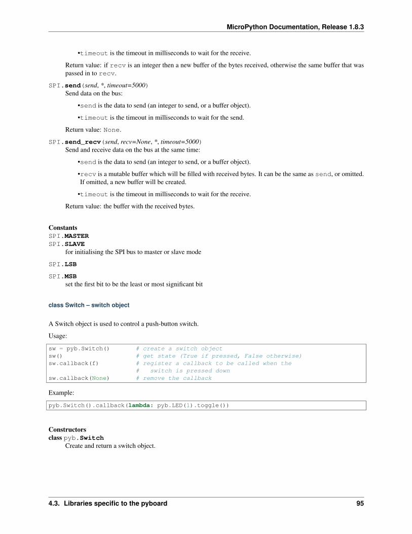
MicroPython Documentation, Release 1.8.3
•timeout is the timeout in milliseconds to wait for the receive.
Return value: if recv is an integer then a new buffer of the bytes received, otherwise the same buffer that waspassed in to recv.
SPI.send(send, *, timeout=5000)Send data on the bus:
•send is the data to send (an integer to send, or a buffer object).
•timeout is the timeout in milliseconds to wait for the send.
Return value: None.
SPI.send_recv(send, recv=None, *, timeout=5000)Send and receive data on the bus at the same time:
•send is the data to send (an integer to send, or a buffer object).
•recv is a mutable buffer which will be filled with received bytes. It can be the same as send, or omitted.If omitted, a new buffer will be created.
•timeout is the timeout in milliseconds to wait for the receive.
Return value: the buffer with the received bytes.
ConstantsSPI.MASTERSPI.SLAVE
for initialising the SPI bus to master or slave mode
SPI.LSB
SPI.MSBset the first bit to be the least or most significant bit
class Switch – switch object
A Switch object is used to control a push-button switch.
Usage:
sw = pyb.Switch() # create a switch objectsw() # get state (True if pressed, False otherwise)sw.callback(f) # register a callback to be called when the
# switch is pressed downsw.callback(None) # remove the callback
Example:
pyb.Switch().callback(lambda: pyb.LED(1).toggle())
Constructorsclass pyb.Switch
Create and return a switch object.
4.3. Libraries specific to the pyboard 95
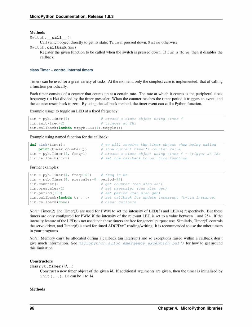
MicroPython Documentation, Release 1.8.3
MethodsSwitch.__call__()
Call switch object directly to get its state: True if pressed down, False otherwise.Switch.callback(fun)
Register the given function to be called when the switch is pressed down. If fun is None, then it disables thecallback.
class Timer – control internal timers
Timers can be used for a great variety of tasks. At the moment, only the simplest case is implemented: that of callinga function periodically.
Each timer consists of a counter that counts up at a certain rate. The rate at which it counts is the peripheral clockfrequency (in Hz) divided by the timer prescaler. When the counter reaches the timer period it triggers an event, andthe counter resets back to zero. By using the callback method, the timer event can call a Python function.
Example usage to toggle an LED at a fixed frequency:
tim = pyb.Timer(4) # create a timer object using timer 4tim.init(freq=2) # trigger at 2Hztim.callback(lambda t:pyb.LED(1).toggle())
Example using named function for the callback:
def tick(timer): # we will receive the timer object when being calledprint(timer.counter()) # show current timer's counter value
tim = pyb.Timer(4, freq=1) # create a timer object using timer 4 - trigger at 1Hztim.callback(tick) # set the callback to our tick function
Further examples:
tim = pyb.Timer(4, freq=100) # freq in Hztim = pyb.Timer(4, prescaler=0, period=99)tim.counter() # get counter (can also set)tim.prescaler(2) # set prescaler (can also get)tim.period(199) # set period (can also get)tim.callback(lambda t: ...) # set callback for update interrupt (t=tim instance)tim.callback(None) # clear callback
Note: Timer(2) and Timer(3) are used for PWM to set the intensity of LED(3) and LED(4) respectively. But thesetimers are only configured for PWM if the intensity of the relevant LED is set to a value between 1 and 254. If theintensity feature of the LEDs is not used then these timers are free for general purpose use. Similarly, Timer(5) controlsthe servo driver, and Timer(6) is used for timed ADC/DAC reading/writing. It is recommended to use the other timersin your programs.
Note: Memory can’t be allocated during a callback (an interrupt) and so exceptions raised within a callback don’tgive much information. See micropython.alloc_emergency_exception_buf() for how to get aroundthis limitation.
Constructorsclass pyb.Timer(id, ...)
Construct a new timer object of the given id. If additional arguments are given, then the timer is initialised byinit(...). id can be 1 to 14.
Methods
96 Chapter 4. MicroPython libraries
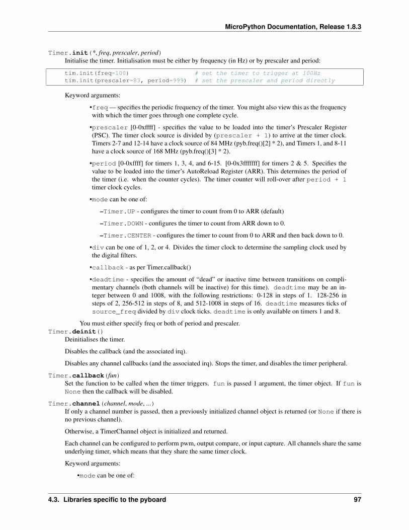
MicroPython Documentation, Release 1.8.3
Timer.init(*, freq, prescaler, period)Initialise the timer. Initialisation must be either by frequency (in Hz) or by prescaler and period:
tim.init(freq=100) # set the timer to trigger at 100Hztim.init(prescaler=83, period=999) # set the prescaler and period directly
Keyword arguments:
•freq — specifies the periodic frequency of the timer. You might also view this as the frequencywith which the timer goes through one complete cycle.
•prescaler [0-0xffff] - specifies the value to be loaded into the timer’s Prescaler Register(PSC). The timer clock source is divided by (prescaler + 1) to arrive at the timer clock.Timers 2-7 and 12-14 have a clock source of 84 MHz (pyb.freq()[2] * 2), and Timers 1, and 8-11have a clock source of 168 MHz (pyb.freq()[3] * 2).
•period [0-0xffff] for timers 1, 3, 4, and 6-15. [0-0x3fffffff] for timers 2 & 5. Specifies thevalue to be loaded into the timer’s AutoReload Register (ARR). This determines the period ofthe timer (i.e. when the counter cycles). The timer counter will roll-over after period + 1timer clock cycles.
•mode can be one of:
–Timer.UP - configures the timer to count from 0 to ARR (default)
–Timer.DOWN - configures the timer to count from ARR down to 0.
–Timer.CENTER - configures the timer to count from 0 to ARR and then back down to 0.
•div can be one of 1, 2, or 4. Divides the timer clock to determine the sampling clock used bythe digital filters.
•callback - as per Timer.callback()
•deadtime - specifies the amount of “dead” or inactive time between transitions on compli-mentary channels (both channels will be inactive) for this time). deadtime may be an in-teger between 0 and 1008, with the following restrictions: 0-128 in steps of 1. 128-256 insteps of 2, 256-512 in steps of 8, and 512-1008 in steps of 16. deadtime measures ticks ofsource_freq divided by div clock ticks. deadtime is only available on timers 1 and 8.
You must either specify freq or both of period and prescaler.Timer.deinit()
Deinitialises the timer.
Disables the callback (and the associated irq).
Disables any channel callbacks (and the associated irq). Stops the timer, and disables the timer peripheral.
Timer.callback(fun)Set the function to be called when the timer triggers. fun is passed 1 argument, the timer object. If fun isNone then the callback will be disabled.
Timer.channel(channel, mode, ...)If only a channel number is passed, then a previously initialized channel object is returned (or None if there isno previous channel).
Otherwise, a TimerChannel object is initialized and returned.
Each channel can be configured to perform pwm, output compare, or input capture. All channels share the sameunderlying timer, which means that they share the same timer clock.
Keyword arguments:
•mode can be one of:
4.3. Libraries specific to the pyboard 97
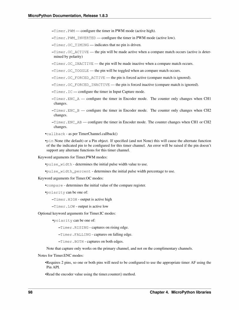
MicroPython Documentation, Release 1.8.3
–Timer.PWM — configure the timer in PWM mode (active high).
–Timer.PWM_INVERTED — configure the timer in PWM mode (active low).
–Timer.OC_TIMING — indicates that no pin is driven.
–Timer.OC_ACTIVE — the pin will be made active when a compare match occurs (active is deter-mined by polarity)
–Timer.OC_INACTIVE — the pin will be made inactive when a compare match occurs.
–Timer.OC_TOGGLE — the pin will be toggled when an compare match occurs.
–Timer.OC_FORCED_ACTIVE — the pin is forced active (compare match is ignored).
–Timer.OC_FORCED_INACTIVE — the pin is forced inactive (compare match is ignored).
–Timer.IC — configure the timer in Input Capture mode.
–Timer.ENC_A — configure the timer in Encoder mode. The counter only changes when CH1changes.
–Timer.ENC_B — configure the timer in Encoder mode. The counter only changes when CH2changes.
–Timer.ENC_AB — configure the timer in Encoder mode. The counter changes when CH1 or CH2changes.
•callback - as per TimerChannel.callback()
•pin None (the default) or a Pin object. If specified (and not None) this will cause the alternate functionof the the indicated pin to be configured for this timer channel. An error will be raised if the pin doesn’tsupport any alternate functions for this timer channel.
Keyword arguments for Timer.PWM modes:
•pulse_width - determines the initial pulse width value to use.
•pulse_width_percent - determines the initial pulse width percentage to use.
Keyword arguments for Timer.OC modes:
•compare - determines the initial value of the compare register.
•polarity can be one of:
–Timer.HIGH - output is active high
–Timer.LOW - output is active low
Optional keyword arguments for Timer.IC modes:
•polarity can be one of:
–Timer.RISING - captures on rising edge.
–Timer.FALLING - captures on falling edge.
–Timer.BOTH - captures on both edges.
Note that capture only works on the primary channel, and not on the complimentary channels.
Notes for Timer.ENC modes:
•Requires 2 pins, so one or both pins will need to be configured to use the appropriate timer AF using thePin API.
•Read the encoder value using the timer.counter() method.
98 Chapter 4. MicroPython libraries
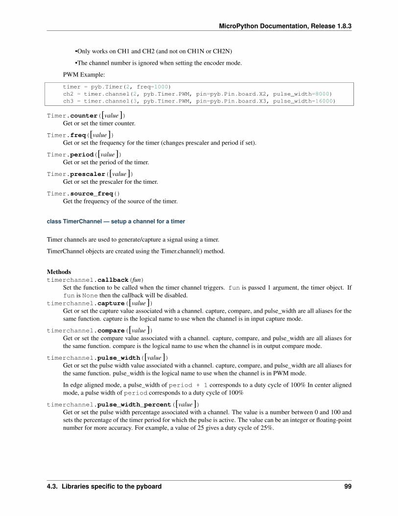
MicroPython Documentation, Release 1.8.3
•Only works on CH1 and CH2 (and not on CH1N or CH2N)
•The channel number is ignored when setting the encoder mode.
PWM Example:
timer = pyb.Timer(2, freq=1000)ch2 = timer.channel(2, pyb.Timer.PWM, pin=pyb.Pin.board.X2, pulse_width=8000)ch3 = timer.channel(3, pyb.Timer.PWM, pin=pyb.Pin.board.X3, pulse_width=16000)
Timer.counter([value])Get or set the timer counter.
Timer.freq([value])Get or set the frequency for the timer (changes prescaler and period if set).
Timer.period([value])Get or set the period of the timer.
Timer.prescaler([value])Get or set the prescaler for the timer.
Timer.source_freq()Get the frequency of the source of the timer.
class TimerChannel — setup a channel for a timer
Timer channels are used to generate/capture a signal using a timer.
TimerChannel objects are created using the Timer.channel() method.
Methodstimerchannel.callback(fun)
Set the function to be called when the timer channel triggers. fun is passed 1 argument, the timer object. Iffun is None then the callback will be disabled.
timerchannel.capture([value])Get or set the capture value associated with a channel. capture, compare, and pulse_width are all aliases for thesame function. capture is the logical name to use when the channel is in input capture mode.
timerchannel.compare([value])Get or set the compare value associated with a channel. capture, compare, and pulse_width are all aliases forthe same function. compare is the logical name to use when the channel is in output compare mode.
timerchannel.pulse_width([value])Get or set the pulse width value associated with a channel. capture, compare, and pulse_width are all aliases forthe same function. pulse_width is the logical name to use when the channel is in PWM mode.
In edge aligned mode, a pulse_width of period + 1 corresponds to a duty cycle of 100% In center alignedmode, a pulse width of period corresponds to a duty cycle of 100%
timerchannel.pulse_width_percent([value])Get or set the pulse width percentage associated with a channel. The value is a number between 0 and 100 andsets the percentage of the timer period for which the pulse is active. The value can be an integer or floating-pointnumber for more accuracy. For example, a value of 25 gives a duty cycle of 25%.
4.3. Libraries specific to the pyboard 99
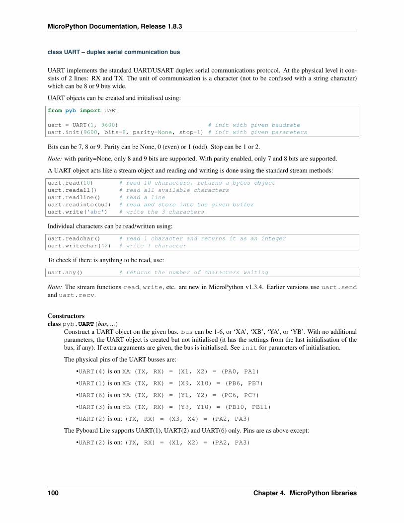
MicroPython Documentation, Release 1.8.3
class UART – duplex serial communication bus
UART implements the standard UART/USART duplex serial communications protocol. At the physical level it con-sists of 2 lines: RX and TX. The unit of communication is a character (not to be confused with a string character)which can be 8 or 9 bits wide.
UART objects can be created and initialised using:
from pyb import UART
uart = UART(1, 9600) # init with given baudrateuart.init(9600, bits=8, parity=None, stop=1) # init with given parameters
Bits can be 7, 8 or 9. Parity can be None, 0 (even) or 1 (odd). Stop can be 1 or 2.
Note: with parity=None, only 8 and 9 bits are supported. With parity enabled, only 7 and 8 bits are supported.
A UART object acts like a stream object and reading and writing is done using the standard stream methods:
uart.read(10) # read 10 characters, returns a bytes objectuart.readall() # read all available charactersuart.readline() # read a lineuart.readinto(buf) # read and store into the given bufferuart.write('abc') # write the 3 characters
Individual characters can be read/written using:
uart.readchar() # read 1 character and returns it as an integeruart.writechar(42) # write 1 character
To check if there is anything to be read, use:
uart.any() # returns the number of characters waiting
Note: The stream functions read, write, etc. are new in MicroPython v1.3.4. Earlier versions use uart.sendand uart.recv.
Constructorsclass pyb.UART(bus, ...)
Construct a UART object on the given bus. bus can be 1-6, or ‘XA’, ‘XB’, ‘YA’, or ‘YB’. With no additionalparameters, the UART object is created but not initialised (it has the settings from the last initialisation of thebus, if any). If extra arguments are given, the bus is initialised. See init for parameters of initialisation.
The physical pins of the UART busses are:
•UART(4) is on XA: (TX, RX) = (X1, X2) = (PA0, PA1)
•UART(1) is on XB: (TX, RX) = (X9, X10) = (PB6, PB7)
•UART(6) is on YA: (TX, RX) = (Y1, Y2) = (PC6, PC7)
•UART(3) is on YB: (TX, RX) = (Y9, Y10) = (PB10, PB11)
•UART(2) is on: (TX, RX) = (X3, X4) = (PA2, PA3)
The Pyboard Lite supports UART(1), UART(2) and UART(6) only. Pins are as above except:
•UART(2) is on: (TX, RX) = (X1, X2) = (PA2, PA3)
100 Chapter 4. MicroPython libraries
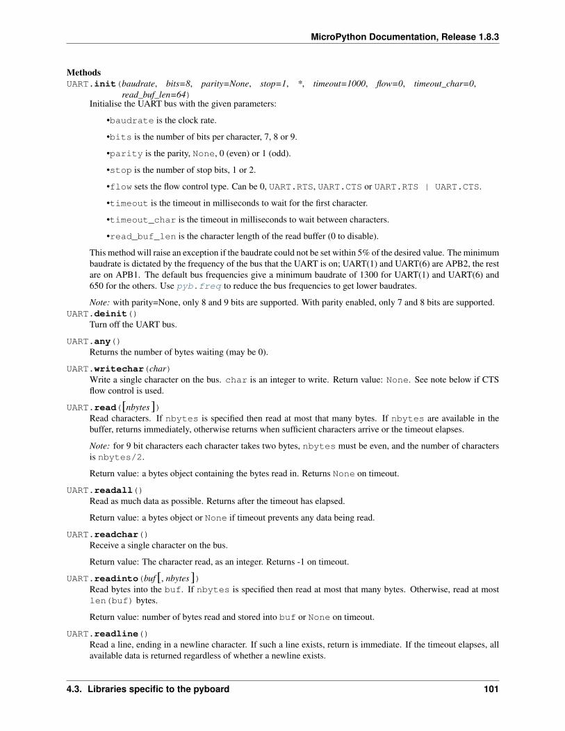
MicroPython Documentation, Release 1.8.3
MethodsUART.init(baudrate, bits=8, parity=None, stop=1, *, timeout=1000, flow=0, timeout_char=0,
read_buf_len=64)Initialise the UART bus with the given parameters:
•baudrate is the clock rate.
•bits is the number of bits per character, 7, 8 or 9.
•parity is the parity, None, 0 (even) or 1 (odd).
•stop is the number of stop bits, 1 or 2.
•flow sets the flow control type. Can be 0, UART.RTS, UART.CTS or UART.RTS | UART.CTS.
•timeout is the timeout in milliseconds to wait for the first character.
•timeout_char is the timeout in milliseconds to wait between characters.
•read_buf_len is the character length of the read buffer (0 to disable).
This method will raise an exception if the baudrate could not be set within 5% of the desired value. The minimumbaudrate is dictated by the frequency of the bus that the UART is on; UART(1) and UART(6) are APB2, the restare on APB1. The default bus frequencies give a minimum baudrate of 1300 for UART(1) and UART(6) and650 for the others. Use pyb.freq to reduce the bus frequencies to get lower baudrates.
Note: with parity=None, only 8 and 9 bits are supported. With parity enabled, only 7 and 8 bits are supported.UART.deinit()
Turn off the UART bus.
UART.any()Returns the number of bytes waiting (may be 0).
UART.writechar(char)Write a single character on the bus. char is an integer to write. Return value: None. See note below if CTSflow control is used.
UART.read([nbytes])Read characters. If nbytes is specified then read at most that many bytes. If nbytes are available in thebuffer, returns immediately, otherwise returns when sufficient characters arrive or the timeout elapses.
Note: for 9 bit characters each character takes two bytes, nbytes must be even, and the number of charactersis nbytes/2.
Return value: a bytes object containing the bytes read in. Returns None on timeout.
UART.readall()Read as much data as possible. Returns after the timeout has elapsed.
Return value: a bytes object or None if timeout prevents any data being read.
UART.readchar()Receive a single character on the bus.
Return value: The character read, as an integer. Returns -1 on timeout.
UART.readinto(buf [, nbytes])Read bytes into the buf. If nbytes is specified then read at most that many bytes. Otherwise, read at mostlen(buf) bytes.
Return value: number of bytes read and stored into buf or None on timeout.
UART.readline()Read a line, ending in a newline character. If such a line exists, return is immediate. If the timeout elapses, allavailable data is returned regardless of whether a newline exists.
4.3. Libraries specific to the pyboard 101
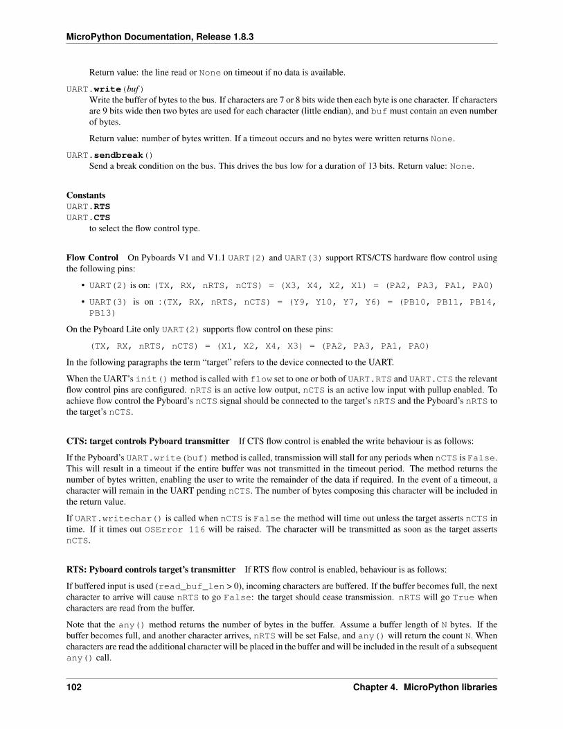
MicroPython Documentation, Release 1.8.3
Return value: the line read or None on timeout if no data is available.
UART.write(buf)Write the buffer of bytes to the bus. If characters are 7 or 8 bits wide then each byte is one character. If charactersare 9 bits wide then two bytes are used for each character (little endian), and buf must contain an even numberof bytes.
Return value: number of bytes written. If a timeout occurs and no bytes were written returns None.
UART.sendbreak()Send a break condition on the bus. This drives the bus low for a duration of 13 bits. Return value: None.
ConstantsUART.RTSUART.CTS
to select the flow control type.
Flow Control On Pyboards V1 and V1.1 UART(2) and UART(3) support RTS/CTS hardware flow control usingthe following pins:
• UART(2) is on: (TX, RX, nRTS, nCTS) = (X3, X4, X2, X1) = (PA2, PA3, PA1, PA0)
• UART(3) is on :(TX, RX, nRTS, nCTS) = (Y9, Y10, Y7, Y6) = (PB10, PB11, PB14,PB13)
On the Pyboard Lite only UART(2) supports flow control on these pins:
(TX, RX, nRTS, nCTS) = (X1, X2, X4, X3) = (PA2, PA3, PA1, PA0)
In the following paragraphs the term “target” refers to the device connected to the UART.
When the UART’s init()method is called with flow set to one or both of UART.RTS and UART.CTS the relevantflow control pins are configured. nRTS is an active low output, nCTS is an active low input with pullup enabled. Toachieve flow control the Pyboard’s nCTS signal should be connected to the target’s nRTS and the Pyboard’s nRTS tothe target’s nCTS.
CTS: target controls Pyboard transmitter If CTS flow control is enabled the write behaviour is as follows:
If the Pyboard’s UART.write(buf) method is called, transmission will stall for any periods when nCTS is False.This will result in a timeout if the entire buffer was not transmitted in the timeout period. The method returns thenumber of bytes written, enabling the user to write the remainder of the data if required. In the event of a timeout, acharacter will remain in the UART pending nCTS. The number of bytes composing this character will be included inthe return value.
If UART.writechar() is called when nCTS is False the method will time out unless the target asserts nCTS intime. If it times out OSError 116 will be raised. The character will be transmitted as soon as the target assertsnCTS.
RTS: Pyboard controls target’s transmitter If RTS flow control is enabled, behaviour is as follows:
If buffered input is used (read_buf_len > 0), incoming characters are buffered. If the buffer becomes full, the nextcharacter to arrive will cause nRTS to go False: the target should cease transmission. nRTS will go True whencharacters are read from the buffer.
Note that the any() method returns the number of bytes in the buffer. Assume a buffer length of N bytes. If thebuffer becomes full, and another character arrives, nRTS will be set False, and any() will return the count N. Whencharacters are read the additional character will be placed in the buffer and will be included in the result of a subsequentany() call.
102 Chapter 4. MicroPython libraries
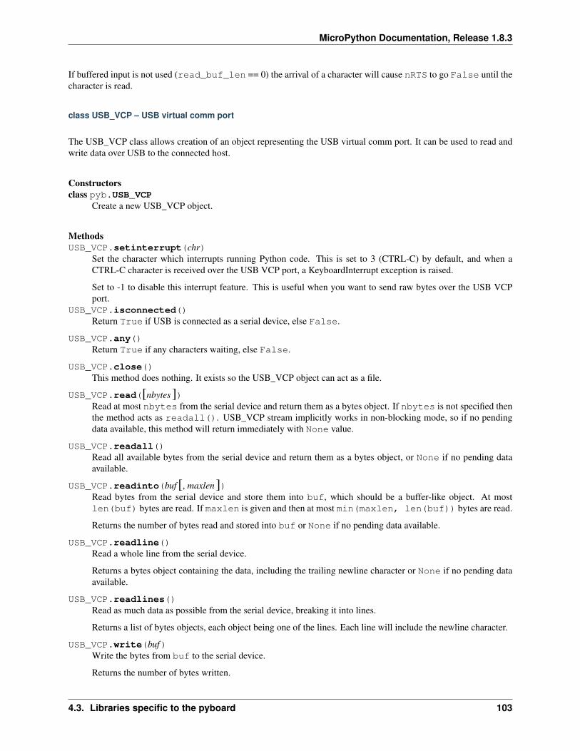
MicroPython Documentation, Release 1.8.3
If buffered input is not used (read_buf_len == 0) the arrival of a character will cause nRTS to go False until thecharacter is read.
class USB_VCP – USB virtual comm port
The USB_VCP class allows creation of an object representing the USB virtual comm port. It can be used to read andwrite data over USB to the connected host.
Constructorsclass pyb.USB_VCP
Create a new USB_VCP object.
MethodsUSB_VCP.setinterrupt(chr)
Set the character which interrupts running Python code. This is set to 3 (CTRL-C) by default, and when aCTRL-C character is received over the USB VCP port, a KeyboardInterrupt exception is raised.
Set to -1 to disable this interrupt feature. This is useful when you want to send raw bytes over the USB VCPport.
USB_VCP.isconnected()Return True if USB is connected as a serial device, else False.
USB_VCP.any()Return True if any characters waiting, else False.
USB_VCP.close()This method does nothing. It exists so the USB_VCP object can act as a file.
USB_VCP.read([nbytes])Read at most nbytes from the serial device and return them as a bytes object. If nbytes is not specified thenthe method acts as readall(). USB_VCP stream implicitly works in non-blocking mode, so if no pendingdata available, this method will return immediately with None value.
USB_VCP.readall()Read all available bytes from the serial device and return them as a bytes object, or None if no pending dataavailable.
USB_VCP.readinto(buf [, maxlen])Read bytes from the serial device and store them into buf, which should be a buffer-like object. At mostlen(buf) bytes are read. If maxlen is given and then at most min(maxlen, len(buf)) bytes are read.
Returns the number of bytes read and stored into buf or None if no pending data available.
USB_VCP.readline()Read a whole line from the serial device.
Returns a bytes object containing the data, including the trailing newline character or None if no pending dataavailable.
USB_VCP.readlines()Read as much data as possible from the serial device, breaking it into lines.
Returns a list of bytes objects, each object being one of the lines. Each line will include the newline character.
USB_VCP.write(buf)Write the bytes from buf to the serial device.
Returns the number of bytes written.
4.3. Libraries specific to the pyboard 103
MicroPython Documentation, Release 1.8.3
USB_VCP.recv(data, *, timeout=5000)Receive data on the bus:
•data can be an integer, which is the number of bytes to receive, or a mutable buffer, which will be filledwith received bytes.
•timeout is the timeout in milliseconds to wait for the receive.
Return value: if data is an integer then a new buffer of the bytes received, otherwise the number of bytes readinto data is returned.
USB_VCP.send(data, *, timeout=5000)Send data over the USB VCP:
•data is the data to send (an integer to send, or a buffer object).
•timeout is the timeout in milliseconds to wait for the send.
Return value: number of bytes sent.
104 Chapter 4. MicroPython libraries
CHAPTER
FIVE
THE PYBOARD HARDWARE
For the pyboard:
• PYBv1.0 schematics and layout (2.4MiB PDF)
• PYBv1.0 metric dimensions (360KiB PDF)
• PYBv1.0 imperial dimensions (360KiB PDF)
For the official skin modules:
• LCD32MKv1.0 schematics (194KiB PDF)
• AMPv1.0 schematics (209KiB PDF)
105

MicroPython Documentation, Release 1.8.3
106 Chapter 5. The pyboard hardware
CHAPTER
SIX
DATASHEETS FOR THE COMPONENTS ON THE PYBOARD
• The microcontroller: STM32F405RGT6 (link to manufacturer’s site)
• The accelerometer: Freescale MMA7660 (800kiB PDF)
• The LDO voltage regulator: Microchip MCP1802 (400kiB PDF)
107

MicroPython Documentation, Release 1.8.3
108 Chapter 6. Datasheets for the components on the pyboard
CHAPTER
SEVEN
DATASHEETS FOR OTHER COMPONENTS
• The LCD display on the LCD touch-sensor skin: Newhaven Display NHD-C12832A1Z-FSW-FBW-3V3(460KiB PDF)
• The touch sensor chip on the LCD touch-sensor skin: Freescale MPR121 (280KiB PDF)
• The digital potentiometer on the audio skin: Microchip MCP4541 (2.7MiB PDF)
109
MicroPython Documentation, Release 1.8.3
110 Chapter 7. Datasheets for other components
CHAPTER
EIGHT
MICROPYTHON LICENSE INFORMATION
The MIT License (MIT)
Copyright (c) 2013-2015 Damien P. George, and others
Permission is hereby granted, free of charge, to any person obtaining a copy of this software and associated documen-tation files (the “Software”), to deal in the Software without restriction, including without limitation the rights to use,copy, modify, merge, publish, distribute, sublicense, and/or sell copies of the Software, and to permit persons to whomthe Software is furnished to do so, subject to the following conditions:
The above copyright notice and this permission notice shall be included in all copies or substantial portions of theSoftware.
THE SOFTWARE IS PROVIDED “AS IS”, WITHOUT WARRANTY OF ANY KIND, EXPRESS OR IMPLIED,INCLUDING BUT NOT LIMITED TO THE WARRANTIES OF MERCHANTABILITY, FITNESS FOR A PAR-TICULAR PURPOSE AND NONINFRINGEMENT. IN NO EVENT SHALL THE AUTHORS OR COPYRIGHTHOLDERS BE LIABLE FOR ANY CLAIM, DAMAGES OR OTHER LIABILITY, WHETHER IN AN ACTIONOF CONTRACT, TORT OR OTHERWISE, ARISING FROM, OUT OF OR IN CONNECTION WITH THE SOFT-WARE OR THE USE OR OTHER DEALINGS IN THE SOFTWARE.
111

MicroPython Documentation, Release 1.8.3
112 Chapter 8. MicroPython license information
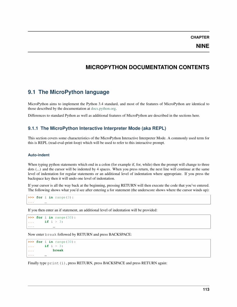
CHAPTER
NINE
MICROPYTHON DOCUMENTATION CONTENTS
9.1 The MicroPython language
MicroPython aims to implement the Python 3.4 standard, and most of the features of MicroPython are identical tothose described by the documentation at docs.python.org.
Differences to standard Python as well as additional features of MicroPython are described in the sections here.
9.1.1 The MicroPython Interactive Interpreter Mode (aka REPL)
This section covers some characteristics of the MicroPython Interactive Interpreter Mode. A commonly used term forthis is REPL (read-eval-print-loop) which will be used to refer to this interactive prompt.
Auto-indent
When typing python statements which end in a colon (for example if, for, while) then the prompt will change to threedots (...) and the cursor will be indented by 4 spaces. When you press return, the next line will continue at the samelevel of indentation for regular statements or an additional level of indentation where appropriate. If you press thebackspace key then it will undo one level of indentation.
If your cursor is all the way back at the beginning, pressing RETURN will then execute the code that you’ve entered.The following shows what you’d see after entering a for statement (the underscore shows where the cursor winds up):
>>> for i in range(3):... _
If you then enter an if statement, an additional level of indentation will be provided:
>>> for i in range(30):... if i > 3:... _
Now enter break followed by RETURN and press BACKSPACE:
>>> for i in range(30):... if i > 3:... break... _
Finally type print(i), press RETURN, press BACKSPACE and press RETURN again:
113
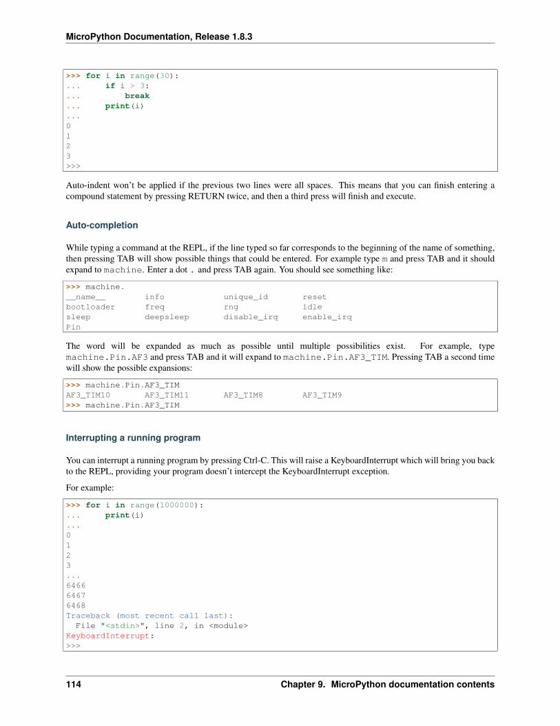
MicroPython Documentation, Release 1.8.3
>>> for i in range(30):... if i > 3:... break... print(i)...0123>>>
Auto-indent won’t be applied if the previous two lines were all spaces. This means that you can finish entering acompound statement by pressing RETURN twice, and then a third press will finish and execute.
Auto-completion
While typing a command at the REPL, if the line typed so far corresponds to the beginning of the name of something,then pressing TAB will show possible things that could be entered. For example type m and press TAB and it shouldexpand to machine. Enter a dot . and press TAB again. You should see something like:
>>> machine.__name__ info unique_id resetbootloader freq rng idlesleep deepsleep disable_irq enable_irqPin
The word will be expanded as much as possible until multiple possibilities exist. For example, typemachine.Pin.AF3 and press TAB and it will expand to machine.Pin.AF3_TIM. Pressing TAB a second timewill show the possible expansions:
>>> machine.Pin.AF3_TIMAF3_TIM10 AF3_TIM11 AF3_TIM8 AF3_TIM9>>> machine.Pin.AF3_TIM
Interrupting a running program
You can interrupt a running program by pressing Ctrl-C. This will raise a KeyboardInterrupt which will bring you backto the REPL, providing your program doesn’t intercept the KeyboardInterrupt exception.
For example:
>>> for i in range(1000000):... print(i)...0123...646664676468Traceback (most recent call last):
File "<stdin>", line 2, in <module>KeyboardInterrupt:>>>
114 Chapter 9. MicroPython documentation contents
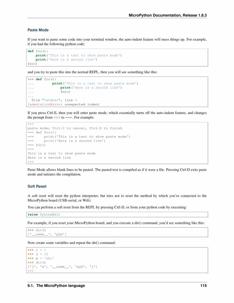
MicroPython Documentation, Release 1.8.3
Paste Mode
If you want to paste some code into your terminal window, the auto-indent feature will mess things up. For example,if you had the following python code:
def foo():print('This is a test to show paste mode')print('Here is a second line')
foo()
and you try to paste this into the normal REPL, then you will see something like this:
>>> def foo():... print('This is a test to show paste mode')... print('Here is a second line')... foo()...
File "<stdin>", line 3IndentationError: unexpected indent
If you press Ctrl-E, then you will enter paste mode, which essentially turns off the auto-indent feature, and changesthe prompt from >>> to ===. For example:
>>>paste mode; Ctrl-C to cancel, Ctrl-D to finish=== def foo():=== print('This is a test to show paste mode')=== print('Here is a second line')=== foo()===This is a test to show paste modeHere is a second line>>>
Paste Mode allows blank lines to be pasted. The pasted text is compiled as if it were a file. Pressing Ctrl-D exits pastemode and initiates the compilation.
Soft Reset
A soft reset will reset the python interpreter, but tries not to reset the method by which you’re connected to theMicroPython board (USB-serial, or Wifi).
You can perform a soft reset from the REPL by pressing Ctrl-D, or from your python code by executing:
raise SystemExit
For example, if you reset your MicroPython board, and you execute a dir() command, you’d see something like this:
>>> dir()['__name__', 'pyb']
Now create some variables and repeat the dir() command:
>>> i = 1>>> j = 23>>> x = 'abc'>>> dir()['j', 'x', '__name__', 'pyb', 'i']>>>
9.1. The MicroPython language 115
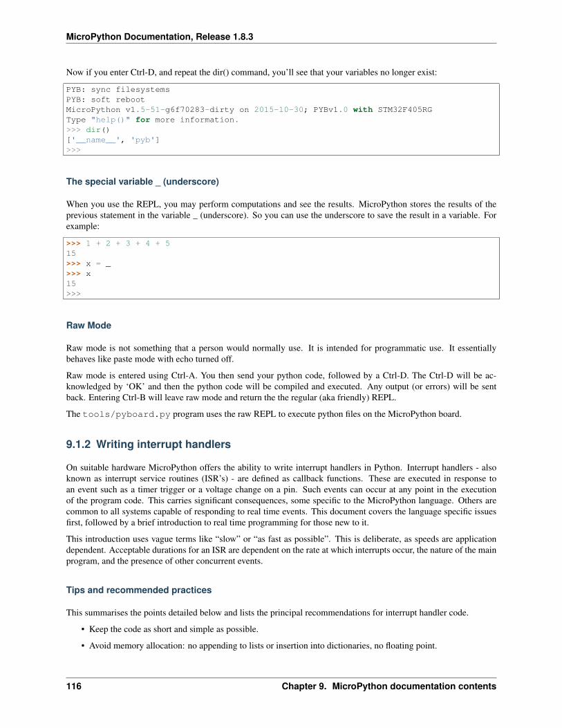
MicroPython Documentation, Release 1.8.3
Now if you enter Ctrl-D, and repeat the dir() command, you’ll see that your variables no longer exist:
PYB: sync filesystemsPYB: soft rebootMicroPython v1.5-51-g6f70283-dirty on 2015-10-30; PYBv1.0 with STM32F405RGType "help()" for more information.>>> dir()['__name__', 'pyb']>>>
The special variable _ (underscore)
When you use the REPL, you may perform computations and see the results. MicroPython stores the results of theprevious statement in the variable _ (underscore). So you can use the underscore to save the result in a variable. Forexample:
>>> 1 + 2 + 3 + 4 + 515>>> x = _>>> x15>>>
Raw Mode
Raw mode is not something that a person would normally use. It is intended for programmatic use. It essentiallybehaves like paste mode with echo turned off.
Raw mode is entered using Ctrl-A. You then send your python code, followed by a Ctrl-D. The Ctrl-D will be ac-knowledged by ‘OK’ and then the python code will be compiled and executed. Any output (or errors) will be sentback. Entering Ctrl-B will leave raw mode and return the the regular (aka friendly) REPL.
The tools/pyboard.py program uses the raw REPL to execute python files on the MicroPython board.
9.1.2 Writing interrupt handlers
On suitable hardware MicroPython offers the ability to write interrupt handlers in Python. Interrupt handlers - alsoknown as interrupt service routines (ISR’s) - are defined as callback functions. These are executed in response toan event such as a timer trigger or a voltage change on a pin. Such events can occur at any point in the executionof the program code. This carries significant consequences, some specific to the MicroPython language. Others arecommon to all systems capable of responding to real time events. This document covers the language specific issuesfirst, followed by a brief introduction to real time programming for those new to it.
This introduction uses vague terms like “slow” or “as fast as possible”. This is deliberate, as speeds are applicationdependent. Acceptable durations for an ISR are dependent on the rate at which interrupts occur, the nature of the mainprogram, and the presence of other concurrent events.
Tips and recommended practices
This summarises the points detailed below and lists the principal recommendations for interrupt handler code.
• Keep the code as short and simple as possible.
• Avoid memory allocation: no appending to lists or insertion into dictionaries, no floating point.
116 Chapter 9. MicroPython documentation contents
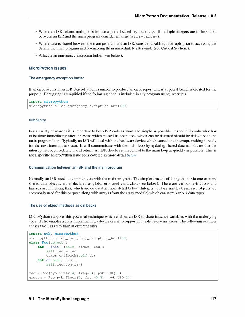
MicroPython Documentation, Release 1.8.3
• Where an ISR returns multiple bytes use a pre-allocated bytearray. If multiple integers are to be sharedbetween an ISR and the main program consider an array (array.array).
• Where data is shared between the main program and an ISR, consider disabling interrupts prior to accessing thedata in the main program and re-enabling them immediately afterwards (see Critical Sections).
• Allocate an emergency exception buffer (see below).
MicroPython Issues
The emergency exception buffer
If an error occurs in an ISR, MicroPython is unable to produce an error report unless a special buffer is created for thepurpose. Debugging is simplified if the following code is included in any program using interrupts.
import micropythonmicropython.alloc_emergency_exception_buf(100)
Simplicity
For a variety of reasons it is important to keep ISR code as short and simple as possible. It should do only what hasto be done immediately after the event which caused it: operations which can be deferred should be delegated to themain program loop. Typically an ISR will deal with the hardware device which caused the interrupt, making it readyfor the next interrupt to occur. It will communicate with the main loop by updating shared data to indicate that theinterrupt has occurred, and it will return. An ISR should return control to the main loop as quickly as possible. This isnot a specific MicroPython issue so is covered in more detail below.
Communication between an ISR and the main program
Normally an ISR needs to communicate with the main program. The simplest means of doing this is via one or moreshared data objects, either declared as global or shared via a class (see below). There are various restrictions andhazards around doing this, which are covered in more detail below. Integers, bytes and bytearray objects arecommonly used for this purpose along with arrays (from the array module) which can store various data types.
The use of object methods as callbacks
MicroPython supports this powerful technique which enables an ISR to share instance variables with the underlyingcode. It also enables a class implementing a device driver to support multiple device instances. The following examplecauses two LED’s to flash at different rates.
import pyb, micropythonmicropython.alloc_emergency_exception_buf(100)class Foo(object):
def __init__(self, timer, led):self.led = ledtimer.callback(self.cb)
def cb(self, tim):self.led.toggle()
red = Foo(pyb.Timer(4, freq=1), pyb.LED(1))greeen = Foo(pyb.Timer(2, freq=0.8), pyb.LED(2))
9.1. The MicroPython language 117
MicroPython Documentation, Release 1.8.3
In this example the red instance associates timer 4 with LED 1: when a timer 4 interrupt occurs red.cb() is calledcausing LED 1 to change state. The green instance operates similarly: a timer 2 interrupt results in the execution ofgreen.cb() and toggles LED 2. The use of instance methods confers two benefits. Firstly a single class enablescode to be shared between multiple hardware instances. Secondly, as a bound method the callback function’s firstargument is self. This enables the callback to access instance data and to save state between successive calls. Forexample, if the class above had a variable self.count set to zero in the constructor, cb() could increment thecounter. The red and green instances would then maintain independent counts of the number of times each LEDhad changed state.
Creation of Python objects
ISR’s cannot create instances of Python objects. This is because MicroPython needs to allocate memory for the objectfrom a store of free memory block called the heap. This is not permitted in an interrupt handler because heap allocationis not re-entrant. In other words the interrupt might occur when the main program is part way through performing anallocation - to maintain the integrity of the heap the interpreter disallows memory allocations in ISR code.
A consequence of this is that ISR’s can’t use floating point arithmetic; this is because floats are Python objects.Similarly an ISR can’t append an item to a list. In practice it can be hard to determine exactly which code constructswill attempt to perform memory allocation and provoke an error message: another reason for keeping ISR code shortand simple.
One way to avoid this issue is for the ISR to use pre-allocated buffers. For example a class constructor creates abytearray instance and a boolean flag. The ISR method assigns data to locations in the buffer and sets the flag.The memory allocation occurs in the main program code when the object is instantiated rather than in the ISR.
The MicroPython library I/O methods usually provide an option to use a pre-allocated buffer. For examplepyb.i2c.recv() can accept a mutable buffer as its first argument: this enables its use in an ISR.
Use of Python objects
A further restriction on objects arises because of the way Python works. When an import statement is executedthe Python code is compiled to bytecode, with one line of code typically mapping to multiple bytecodes. When thecode runs the interpreter reads each bytecode and executes it as a series of machine code instructions. Given thatan interrupt can occur at any time between machine code instructions, the original line of Python code may be onlypartially executed. Consequently a Python object such as a set, list or dictionary modified in the main loop may lackinternal consistency at the moment the interrupt occurs.
A typical outcome is as follows. On rare occasions the ISR will run at the precise moment in time when the objectis partially updated. When the ISR tries to read the object, a crash results. Because such problems typically occur onrare, random occasions they can be hard to diagnose. There are ways to circumvent this issue, described in CriticalSections below.
It is important to be clear about what constitutes the modification of an object. An alteration to a built-in type such asa dictionary is problematic. Altering the contents of an array or bytearray is not. This is because bytes or words arewritten as a single machine code instruction which is not interruptible: in the parlance of real time programming thewrite is atomic. A user defined object might instantiate an integer, array or bytearray. It is valid for both the main loopand the ISR to alter the contents of these.
MicroPython supports integers of arbitrary precision. Values between 2**30 -1 and -2**30 will be stored in a singlemachine word. Larger values are stored as Python objects. Consequently changes to long integers cannot be consideredatomic. The use of long integers in ISR’s is unsafe because memory allocation may be attempted as the variable’s valuechanges.
118 Chapter 9. MicroPython documentation contents
MicroPython Documentation, Release 1.8.3
Overcoming the float limitation
In general it is best to avoid using floats in ISR code: hardware devices normally handle integers and conversion tofloats is normally done in the main loop. However there are a few DSP algorithms which require floating point. Onplatforms with hardware floating point (such as the Pyboard) the inline ARM Thumb assembler can be used to workround this limitation. This is because the processor stores float values in a machine word; values can be shared betweenthe ISR and main program code via an array of floats.
Exceptions
If an ISR raises an exception it will not propagate to the main loop. The interrupt will be disabled unless the exceptionis handled by the ISR code.
General Issues
This is merely a brief introduction to the subject of real time programming. Beginners should note that design errorsin real time programs can lead to faults which are particularly hard to diagnose. This is because they can occur rarelyand at intervals which are essentially random. It is crucial to get the initial design right and to anticipate issues beforethey arise. Both interrupt handlers and the main program need to be designed with an appreciation of the followingissues.
Interrupt Handler Design
As mentioned above, ISR’s should be designed to be as simple as possible. They should always return in a short,predictable period of time. This is important because when the ISR is running, the main loop is not: inevitably themain loop experiences pauses in its execution at random points in the code. Such pauses can be a source of hard todiagnose bugs particularly if their duration is long or variable. In order to understand the implications of ISR run time,a basic grasp of interrupt priorities is required.
Interrupts are organised according to a priority scheme. ISR code may itself be interrupted by a higher priorityinterrupt. This has implications if the two interrupts share data (see Critical Sections below). If such an interruptoccurs it interposes a delay into the ISR code. If a lower priority interrupt occurs while the ISR is running, it will bedelayed until the ISR is complete: if the delay is too long, the lower priority interrupt may fail. A further issue withslow ISR’s is the case where a second interrupt of the same type occurs during its execution. The second interrupt willbe handled on termination of the first. However if the rate of incoming interrupts consistently exceeds the capacity ofthe ISR to service them the outcome will not be a happy one.
Consequently looping constructs should be avoided or minimised. I/O to devices other than to the interrupting deviceshould normally be avoided: I/O such as disk access, print statements and UART access is relatively slow, and itsduration may vary. A further issue here is that filesystem functions are not reentrant: using filesystem I/O in an ISRand the main program would be hazardous. Crucially ISR code should not wait on an event. I/O is acceptable if thecode can be guaranteed to return in a predictable period, for example toggling a pin or LED. Accessing the interruptingdevice via I2C or SPI may be necessary but the time taken for such accesses should be calculated or measured and itsimpact on the application assessed.
There is usually a need to share data between the ISR and the main loop. This may be done either through globalvariables or via class or instance variables. Variables are typically integer or boolean types, or integer or byte arrays(a pre-allocated integer array offers faster access than a list). Where multiple values are modified by the ISR it isnecessary to consider the case where the interrupt occurs at a time when the main program has accessed some, but notall, of the values. This can lead to inconsistencies.
Consider the following design. An ISR stores incoming data in a bytearray, then adds the number of bytes received toan integer representing total bytes ready for processing. The main program reads the number of bytes, processes the
9.1. The MicroPython language 119
MicroPython Documentation, Release 1.8.3
bytes, then clears down the number of bytes ready. This will work until an interrupt occurs just after the main programhas read the number of bytes. The ISR puts the added data into the buffer and updates the number received, but themain program has already read the number, so processes the data originally received. The newly arrived bytes are lost.
There are various ways of avoiding this hazard, the simplest being to use a circular buffer. If it is not possible to use astructure with inherent thread safety other ways are described below.
Reentrancy
A potential hazard may occur if a function or method is shared between the main program and one or more ISR’s orbetween multiple ISR’s. The issue here is that the function may itself be interrupted and a further instance of thatfunction run. If this is to occur, the function must be designed to be reentrant. How this is done is an advanced topicbeyond the scope of this tutorial.
Critical Sections
An example of a critical section of code is one which accesses more than one variable which can be affected by an ISR.If the interrupt happens to occur between accesses to the individual variables, their values will be inconsistent. Thisis an instance of a hazard known as a race condition: the ISR and the main program loop race to alter the variables.To avoid inconsistency a means must be employed to ensure that the ISR does not alter the values for the duration ofthe critical section. One way to achieve this is to issue pyb.disable_irq() before the start of the section, andpyb.enable_irq() at the end. Here is an example of this approach:
import pyb, micropython, arraymicropython.alloc_emergency_exception_buf(100)
class BoundsException(Exception):pass
ARRAYSIZE = const(20)index = 0data = array.array('i', 0 for x in range(ARRAYSIZE))
def callback1(t):global data, indexfor x in range(5):
data[index] = pyb.rng() # simulate inputindex += 1if index >= ARRAYSIZE:
raise BoundsException('Array bounds exceeded')
tim4 = pyb.Timer(4, freq=100, callback=callback1)
for loop in range(1000):if index > 0:
irq_state = pyb.disable_irq() # Start of critical sectionfor x in range(index):
print(data[x])index = 0pyb.enable_irq(irq_state) # End of critical sectionprint('loop {}'.format(loop))
pyb.delay(1)
tim4.callback(None)
A critical section can comprise a single line of code and a single variable. Consider the following code fragment.
120 Chapter 9. MicroPython documentation contents
MicroPython Documentation, Release 1.8.3
count = 0def cb(): # An interrupt callback
count +=1def main():
# Code to set up the interrupt callback omittedwhile True:
count += 1
This example illustrates a subtle source of bugs. The line count += 1 in the main loop carries a specific racecondition hazard known as a read-modify-write. This is a classic cause of bugs in real time systems. In the main loopMicroPython reads the value of t.counter, adds 1 to it, and writes it back. On rare occasions the interrupt occursafter the read and before the write. The interrupt modifies t.counter but its change is overwritten by the main loopwhen the ISR returns. In a real system this could lead to rare, unpredictable failures.
As mentioned above, care should be taken if an instance of a Python built in type is modified in the main code and thatinstance is accessed in an ISR. The code performing the modification should be regarded as a critical section to ensurethat the instance is in a valid state when the ISR runs.
Particular care needs to be taken if a dataset is shared between different ISR’s. The hazard here is that the higherpriority interrupt may occur when the lower priority one has partially updated the shared data. Dealing with thissituation is an advanced topic beyond the scope of this introduction other than to note that mutex objects describedbelow can sometimes be used.
Disabling interrupts for the duration of a critical section is the usual and simplest way to proceed, but it disables allinterrupts rather than merely the one with the potential to cause problems. It is generally undesirable to disable aninterrupt for long. In the case of timer interrupts it introduces variability to the time when a callback occurs. In thecase of device interrupts, it can lead to the device being serviced too late with possible loss of data or overrun errorsin the device hardware. Like ISR’s, a critical section in the main code should have a short, predictable duration.
An approach to dealing with critical sections which radically reduces the time for which interrupts are disabled is touse an object termed a mutex (name derived from the notion of mutual exclusion). The main program locks the mutexbefore running the critical section and unlocks it at the end. The ISR tests whether the mutex is locked. If it is, it avoidsthe critical section and returns. The design challenge is defining what the ISR should do in the event that access to thecritical variables is denied. A simple example of a mutex may be found here. Note that the mutex code does disableinterrupts, but only for the duration of eight machine instructions: the benefit of this approach is that other interruptsare virtually unaffected.
9.1.3 Maximising Python Speed
This tutorial describes ways of improving the performance of MicroPython code. Optimisations involving other lan-guages are covered elsewhere, namely the use of modules written in C and the MicroPython inline ARM Thumb-2assembler.
The process of developing high performance code comprises the following stages which should be performed in theorder listed.
• Design for speed.
• Code and debug.
Optimisation steps:
• Identify the slowest section of code.
• Improve the efficiency of the Python code.
• Use the native code emitter.
• Use the viper code emitter.
9.1. The MicroPython language 121
MicroPython Documentation, Release 1.8.3
Designing for speed
Performance issues should be considered at the outset. This involves taking a view on the sections of code which aremost performance critical and devoting particular attention to their design. The process of optimisation begins whenthe code has been tested: if the design is correct at the outset optimisation will be straightforward and may actually beunnecessary.
Algorithms
The most important aspect of designing any routine for performance is ensuring that the best algorithm is employed.This is a topic for textbooks rather than for a MicroPython guide but spectacular performance gains can sometimes beachieved by adopting algorithms known for their efficiency.
RAM Allocation
To design efficient MicroPython code it is necessary to have an understanding of the way the interpreter allocatesRAM. When an object is created or grows in size (for example where an item is appended to a list) the necessaryRAM is allocated from a block known as the heap. This takes a significant amount of time; further it will on occasiontrigger a process known as garbage collection which can take several milliseconds.
Consequently the performance of a function or method can be improved if an object is created once only and notpermitted to grow in size. This implies that the object persists for the duration of its use: typically it will be instantiatedin a class constructor and used in various methods.
This is covered in further detail Controlling garbage collection below.
Buffers
An example of the above is the common case where a buffer is required, such as one used for communication witha device. A typical driver will create the buffer in the constructor and use it in its I/O methods which will be calledrepeatedly.
The MicroPython libraries typically provide support for pre-allocated buffers. For example, objects which supportstream interface (e.g., file or UART) provide read() method which allocate new buffer for read data, but also areadinto() method to read data into an existing buffer.
Floating Point
Some MicroPython ports allocate floating point numbers on heap. Some other ports may lack dedicated floating-pointcoprocessor, and perform arithmetic operations on them in “software” at considerably lower speed than on integers.Where performance is important, use integer operations and restrict the use of floating point to sections of the codewhere performance is not paramount. For example, capture ADC readings as integers values to an array in one quickgo, and only then convert them to floating-point numbers for signal processing.
Arrays
Consider the use of the various types of array classes as an alternative to lists. The array module supports variouselement types with 8-bit elements supported by Python’s built in bytes and bytearray classes. These data struc-tures all store elements in contiguous memory locations. Once again to avoid memory allocation in critical code theseshould be pre-allocated and passed as arguments or as bound objects.
122 Chapter 9. MicroPython documentation contents
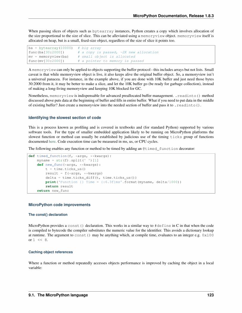
MicroPython Documentation, Release 1.8.3
When passing slices of objects such as bytearray instances, Python creates a copy which involves allocation ofthe size proportional to the size of slice. This can be alleviated using a memoryview object. memoryview itself isallocated on heap, but is a small, fixed-size object, regardless of the size of slice it points too.
ba = bytearray(10000) # big arrayfunc(ba[30:2000]) # a copy is passed, ~2K new allocationmv = memoryview(ba) # small object is allocatedfunc(mv[30:2000]) # a pointer to memory is passed
A memoryview can only be applied to objects supporting the buffer protocol - this includes arrays but not lists. Smallcaveat is that while memoryview object is live, it also keeps alive the original buffer object. So, a memoryview isn’ta universal panacea. For instance, in the example above, if you are done with 10K buffer and just need those bytes30:2000 from it, it may be better to make a slice, and let the 10K buffer go (be ready for garbage collection), insteadof making a long-living memoryview and keeping 10K blocked for GC.
Nonetheless, memoryview is indispensable for advanced preallocated buffer management. .readinto() methoddiscussed above puts data at the beginning of buffer and fills in entire buffer. What if you need to put data in the middleof existing buffer? Just create a memoryview into the needed section of buffer and pass it to .readinto().
Identifying the slowest section of code
This is a process known as profiling and is covered in textbooks and (for standard Python) supported by varioussoftware tools. For the type of smaller embedded application likely to be running on MicroPython platforms theslowest function or method can usually be established by judicious use of the timing ticks group of functionsdocumented here. Code execution time can be measured in ms, us, or CPU cycles.
The following enables any function or method to be timed by adding an @timed_function decorator:
def timed_function(f, *args, **kwargs):myname = str(f).split(' ')[1]def new_func(*args, **kwargs):
t = time.ticks_us()result = f(*args, **kwargs)delta = time.ticks_diff(t, time.ticks_us())print('Function {} Time = {:6.3f}ms'.format(myname, delta/1000))return result
return new_func
MicroPython code improvements
The const() declaration
MicroPython provides a const() declaration. This works in a similar way to #define in C in that when the codeis compiled to bytecode the compiler substitutes the numeric value for the identifier. This avoids a dictionary lookupat runtime. The argument to const() may be anything which, at compile time, evaluates to an integer e.g. 0x100or 1 << 8.
Caching object references
Where a function or method repeatedly accesses objects performance is improved by caching the object in a localvariable:
9.1. The MicroPython language 123

MicroPython Documentation, Release 1.8.3
class foo(object):def __init__(self):
ba = bytearray(100)def bar(self, obj_display):
ba_ref = self.bafb = obj_display.framebuffer# iterative code using these two objects
This avoids the need repeatedly to look up self.ba and obj_display.framebuffer in the body of the methodbar().
Controlling garbage collection
When memory allocation is required, MicroPython attempts to locate an adequately sized block on the heap. This mayfail, usually because the heap is cluttered with objects which are no longer referenced by code. If a failure occurs, theprocess known as garbage collection reclaims the memory used by these redundant objects and the allocation is thentried again - a process which can take several milliseconds.
There are benefits in pre-empting this by periodically issuing gc.collect(). Firstly doing a collection before it isactually required is quicker - typically on the order of 1ms if done frequently. Secondly you can determine the pointin code where this time is used rather than have a longer delay occur at random points, possibly in a speed criticalsection. Finally performing collections regularly can reduce fragmentation in the heap. Severe fragmentation can leadto non-recoverable allocation failures.
Accessing hardware directly
This comes into the category of more advanced programming and involves some knowledge of the target MCU.Consider the example of toggling an output pin on the Pyboard. The standard approach would be to write
mypin.value(mypin.value() ^ 1) # mypin was instantiated as an output pin
This involves the overhead of two calls to the Pin instance’s value() method. This overhead can be eliminated byperforming a read/write to the relevant bit of the chip’s GPIO port output data register (odr). To facilitate this the stmmodule provides a set of constants providing the addresses of the relevant registers. A fast toggle of pin P4 (CPU pinA14) - corresponding to the green LED - can be performed as follows:
BIT14 = const(1 << 14)stm.mem16[stm.GPIOA + stm.GPIO_ODR] ^= BIT14
The Native code emitter
This causes the MicroPython compiler to emit ARM native opcodes rather than bytecode. It covers the bulk of thePython language so most functions will require no adaptation (but see below). It is invoked by means of a functiondecorator:
@micropython.nativedef foo(self, arg):
buf = self.linebuf # Cached object# code
There are certain limitations in the current implementation of the native code emitter.
• Context managers are not supported (the with statement).
• Generators are not supported.
124 Chapter 9. MicroPython documentation contents
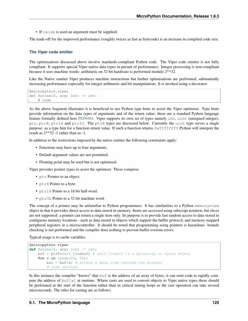
MicroPython Documentation, Release 1.8.3
• If raise is used an argument must be supplied.
The trade-off for the improved performance (roughly twices as fast as bytecode) is an increase in compiled code size.
The Viper code emitter
The optimisations discussed above involve standards-compliant Python code. The Viper code emitter is not fullycompliant. It supports special Viper native data types in pursuit of performance. Integer processing is non-compliantbecause it uses machine words: arithmetic on 32 bit hardware is performed modulo 2**32.
Like the Native emitter Viper produces machine instructions but further optimisations are performed, substantiallyincreasing performance especially for integer arithmetic and bit manipulations. It is invoked using a decorator:
@micropython.viperdef foo(self, arg: int) -> int:
# code
As the above fragment illustrates it is beneficial to use Python type hints to assist the Viper optimiser. Type hintsprovide information on the data types of arguments and of the return value; these are a standard Python languagefeature formally defined here PEP0484. Viper supports its own set of types namely int, uint (unsigned integer),ptr, ptr8, ptr16 and ptr32. The ptrX types are discussed below. Currently the uint type serves a singlepurpose: as a type hint for a function return value. If such a function returns 0xffffffff Python will interpret theresult as 2**32 -1 rather than as -1.
In addition to the restrictions imposed by the native emitter the following constraints apply:
• Functions may have up to four arguments.
• Default argument values are not permitted.
• Floating point may be used but is not optimised.
Viper provides pointer types to assist the optimiser. These comprise
• ptr Pointer to an object.
• ptr8 Points to a byte.
• ptr16 Points to a 16 bit half-word.
• ptr32 Points to a 32 bit machine word.
The concept of a pointer may be unfamiliar to Python programmers. It has similarities to a Python memoryviewobject in that it provides direct access to data stored in memory. Items are accessed using subscript notation, but slicesare not supported: a pointer can return a single item only. Its purpose is to provide fast random access to data stored incontiguous memory locations - such as data stored in objects which support the buffer protocol, and memory-mappedperipheral registers in a microcontroller. It should be noted that programming using pointers is hazardous: boundschecking is not performed and the compiler does nothing to prevent buffer overrun errors.
Typical usage is to cache variables:
@micropython.viperdef foo(self, arg: int) -> int:
buf = ptr8(self.linebuf) # self.linebuf is a bytearray or bytes objectfor x in range(20, 30):
bar = buf[x] # Access a data item through the pointer# code omitted
In this instance the compiler “knows” that buf is the address of an array of bytes; it can emit code to rapidly com-pute the address of buf[x] at runtime. Where casts are used to convert objects to Viper native types these shouldbe performed at the start of the function rather than in critical timing loops as the cast operation can take severalmicroseconds. The rules for casting are as follows:
9.1. The MicroPython language 125
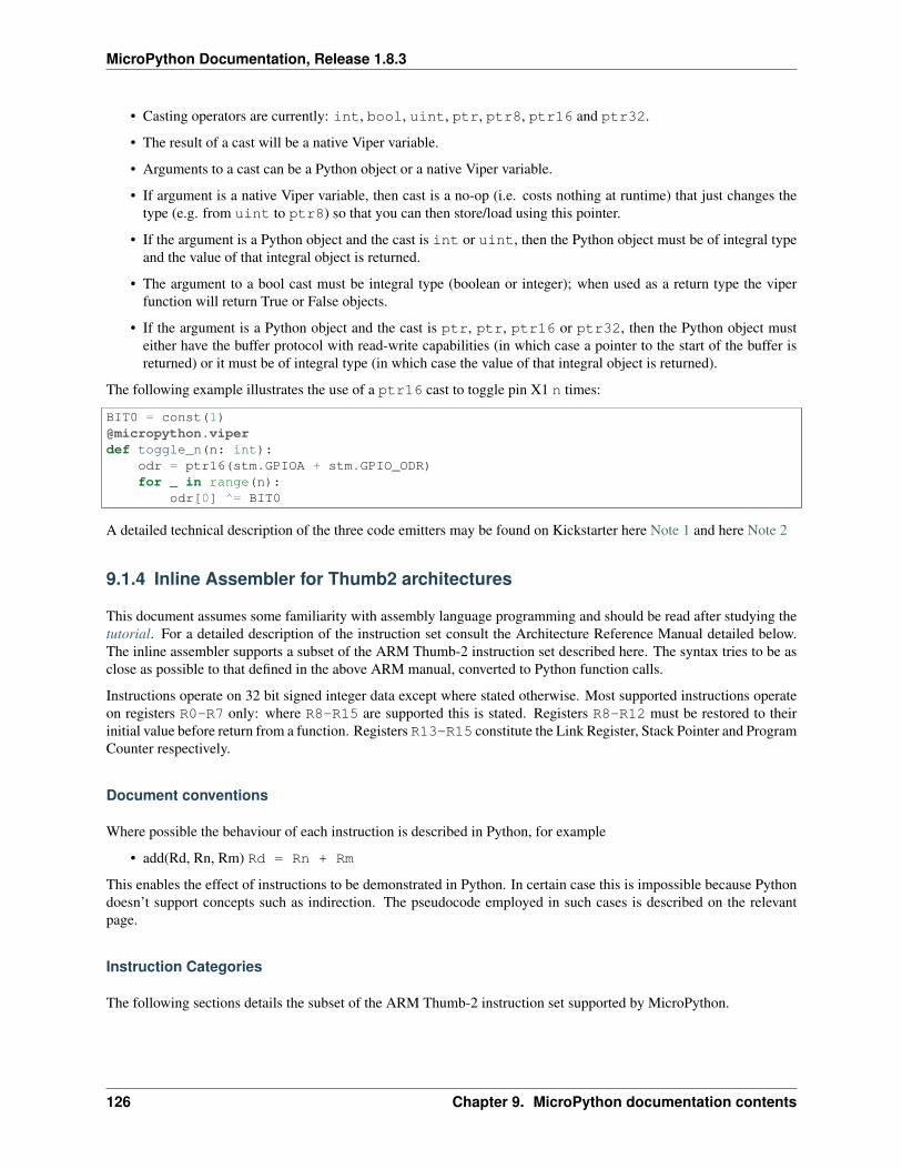
MicroPython Documentation, Release 1.8.3
• Casting operators are currently: int, bool, uint, ptr, ptr8, ptr16 and ptr32.
• The result of a cast will be a native Viper variable.
• Arguments to a cast can be a Python object or a native Viper variable.
• If argument is a native Viper variable, then cast is a no-op (i.e. costs nothing at runtime) that just changes thetype (e.g. from uint to ptr8) so that you can then store/load using this pointer.
• If the argument is a Python object and the cast is int or uint, then the Python object must be of integral typeand the value of that integral object is returned.
• The argument to a bool cast must be integral type (boolean or integer); when used as a return type the viperfunction will return True or False objects.
• If the argument is a Python object and the cast is ptr, ptr, ptr16 or ptr32, then the Python object musteither have the buffer protocol with read-write capabilities (in which case a pointer to the start of the buffer isreturned) or it must be of integral type (in which case the value of that integral object is returned).
The following example illustrates the use of a ptr16 cast to toggle pin X1 n times:
BIT0 = const(1)@micropython.viperdef toggle_n(n: int):
odr = ptr16(stm.GPIOA + stm.GPIO_ODR)for _ in range(n):
odr[0] ^= BIT0
A detailed technical description of the three code emitters may be found on Kickstarter here Note 1 and here Note 2
9.1.4 Inline Assembler for Thumb2 architectures
This document assumes some familiarity with assembly language programming and should be read after studying thetutorial. For a detailed description of the instruction set consult the Architecture Reference Manual detailed below.The inline assembler supports a subset of the ARM Thumb-2 instruction set described here. The syntax tries to be asclose as possible to that defined in the above ARM manual, converted to Python function calls.
Instructions operate on 32 bit signed integer data except where stated otherwise. Most supported instructions operateon registers R0-R7 only: where R8-R15 are supported this is stated. Registers R8-R12 must be restored to theirinitial value before return from a function. Registers R13-R15 constitute the Link Register, Stack Pointer and ProgramCounter respectively.
Document conventions
Where possible the behaviour of each instruction is described in Python, for example
• add(Rd, Rn, Rm) Rd = Rn + Rm
This enables the effect of instructions to be demonstrated in Python. In certain case this is impossible because Pythondoesn’t support concepts such as indirection. The pseudocode employed in such cases is described on the relevantpage.
Instruction Categories
The following sections details the subset of the ARM Thumb-2 instruction set supported by MicroPython.
126 Chapter 9. MicroPython documentation contents

MicroPython Documentation, Release 1.8.3
Register move instructions
Document conventions Notation: Rd, Rn denote ARM registers R0-R15. immN denotes an immediate valuehaving a width of N bits. These instructions affect the condition flags.
Register moves Where immediate values are used, these are zero-extended to 32 bits. Thus mov(R0, 0xff) willset R0 to 255.
• mov(Rd, imm8) Rd = imm8
• mov(Rd, Rn) Rd = Rn
• movw(Rd, imm16) Rd = imm16
• movt(Rd, imm16) Rd = (Rd & 0xffff) | (imm16 << 16)
movt writes an immediate value to the top halfword of the destination register. It does not affect the contents of thebottom halfword.
• movwt(Rd, imm32) Rd = imm32
movwt is a pseudo-instruction: the MicroPython assembler emits a movw followed by a movt to move a 32-bit valueinto Rd.
Load register from memory
Document conventions Notation: Rt, Rn denote ARM registers R0-R7 except where stated. immN representsan immediate value having a width of N bits hence imm5 is constrained to the range 0-31. [Rn + immN] is thecontents of the memory address obtained by adding Rn and the offset immN. Offsets are measured in bytes. Theseinstructions affect the condition flags.
Register Load
• ldr(Rt, [Rn, imm7]) Rt = [Rn + imm7] Load a 32 bit word
• ldrb(Rt, [Rn, imm5]) Rt = [Rn + imm5] Load a byte
• ldrh(Rt, [Rn, imm6]) Rt = [Rn + imm6] Load a 16 bit half word
Where a byte or half word is loaded, it is zero-extended to 32 bits.
The specified immediate offsets are measured in bytes. Hence in the case of ldr the 7 bit value enables 32 bit wordaligned values to be accessed with a maximum offset of 31 words. In the case of ldrh the 6 bit value enables 16 bithalf-word aligned values to be accessed with a maximum offset of 31 half-words.
Store register to memory
Document conventions Notation: Rt, Rn denote ARM registers R0-R7 except where stated. immN representsan immediate value having a width of N bits hence imm5 is constrained to the range 0-31. [Rn + imm5] is thecontents of the memory address obtained by adding Rn and the offset imm5. Offsets are measured in bytes. Theseinstructions do not affect the condition flags.
9.1. The MicroPython language 127
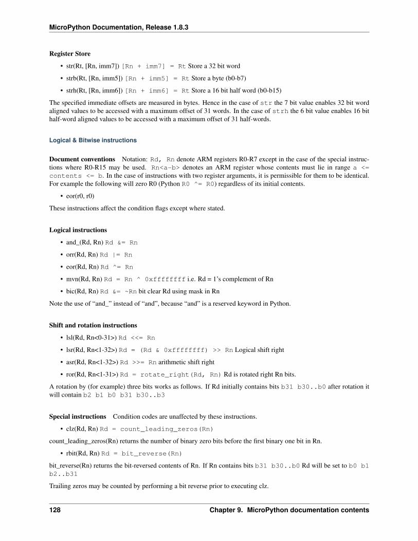
MicroPython Documentation, Release 1.8.3
Register Store
• str(Rt, [Rn, imm7]) [Rn + imm7] = Rt Store a 32 bit word
• strb(Rt, [Rn, imm5]) [Rn + imm5] = Rt Store a byte (b0-b7)
• strh(Rt, [Rn, imm6]) [Rn + imm6] = Rt Store a 16 bit half word (b0-b15)
The specified immediate offsets are measured in bytes. Hence in the case of str the 7 bit value enables 32 bit wordaligned values to be accessed with a maximum offset of 31 words. In the case of strh the 6 bit value enables 16 bithalf-word aligned values to be accessed with a maximum offset of 31 half-words.
Logical & Bitwise instructions
Document conventions Notation: Rd, Rn denote ARM registers R0-R7 except in the case of the special instruc-tions where R0-R15 may be used. Rn<a-b> denotes an ARM register whose contents must lie in range a <=contents <= b. In the case of instructions with two register arguments, it is permissible for them to be identical.For example the following will zero R0 (Python R0 ^= R0) regardless of its initial contents.
• eor(r0, r0)
These instructions affect the condition flags except where stated.
Logical instructions
• and_(Rd, Rn) Rd &= Rn
• orr(Rd, Rn) Rd |= Rn
• eor(Rd, Rn) Rd ^= Rn
• mvn(Rd, Rn) Rd = Rn ^ 0xffffffff i.e. Rd = 1’s complement of Rn
• bic(Rd, Rn) Rd &= ~Rn bit clear Rd using mask in Rn
Note the use of “and_” instead of “and”, because “and” is a reserved keyword in Python.
Shift and rotation instructions
• lsl(Rd, Rn<0-31>) Rd <<= Rn
• lsr(Rd, Rn<1-32>) Rd = (Rd & 0xffffffff) >> Rn Logical shift right
• asr(Rd, Rn<1-32>) Rd >>= Rn arithmetic shift right
• ror(Rd, Rn<1-31>) Rd = rotate_right(Rd, Rn) Rd is rotated right Rn bits.
A rotation by (for example) three bits works as follows. If Rd initially contains bits b31 b30..b0 after rotation itwill contain b2 b1 b0 b31 b30..b3
Special instructions Condition codes are unaffected by these instructions.
• clz(Rd, Rn) Rd = count_leading_zeros(Rn)
count_leading_zeros(Rn) returns the number of binary zero bits before the first binary one bit in Rn.
• rbit(Rd, Rn) Rd = bit_reverse(Rn)
bit_reverse(Rn) returns the bit-reversed contents of Rn. If Rn contains bits b31 b30..b0 Rd will be set to b0 b1b2..b31
Trailing zeros may be counted by performing a bit reverse prior to executing clz.
128 Chapter 9. MicroPython documentation contents
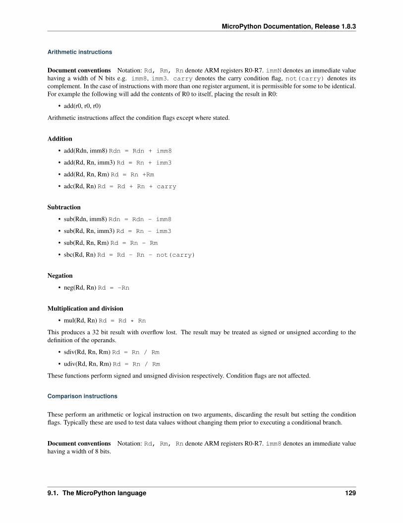
MicroPython Documentation, Release 1.8.3
Arithmetic instructions
Document conventions Notation: Rd, Rm, Rn denote ARM registers R0-R7. immN denotes an immediate valuehaving a width of N bits e.g. imm8, imm3. carry denotes the carry condition flag, not(carry) denotes itscomplement. In the case of instructions with more than one register argument, it is permissible for some to be identical.For example the following will add the contents of R0 to itself, placing the result in R0:
• add(r0, r0, r0)
Arithmetic instructions affect the condition flags except where stated.
Addition
• add(Rdn, imm8) Rdn = Rdn + imm8
• add(Rd, Rn, imm3) Rd = Rn + imm3
• add(Rd, Rn, Rm) Rd = Rn +Rm
• adc(Rd, Rn) Rd = Rd + Rn + carry
Subtraction
• sub(Rdn, imm8) Rdn = Rdn - imm8
• sub(Rd, Rn, imm3) Rd = Rn - imm3
• sub(Rd, Rn, Rm) Rd = Rn - Rm
• sbc(Rd, Rn) Rd = Rd - Rn - not(carry)
Negation
• neg(Rd, Rn) Rd = -Rn
Multiplication and division
• mul(Rd, Rn) Rd = Rd * Rn
This produces a 32 bit result with overflow lost. The result may be treated as signed or unsigned according to thedefinition of the operands.
• sdiv(Rd, Rn, Rm) Rd = Rn / Rm
• udiv(Rd, Rn, Rm) Rd = Rn / Rm
These functions perform signed and unsigned division respectively. Condition flags are not affected.
Comparison instructions
These perform an arithmetic or logical instruction on two arguments, discarding the result but setting the conditionflags. Typically these are used to test data values without changing them prior to executing a conditional branch.
Document conventions Notation: Rd, Rm, Rn denote ARM registers R0-R7. imm8 denotes an immediate valuehaving a width of 8 bits.
9.1. The MicroPython language 129

MicroPython Documentation, Release 1.8.3
The Application Program Status Register (APSR) This contains four bits which are tested by the conditionalbranch instructions. Typically a conditional branch will test multiple bits, for example bge(LABEL). The mean-ing of condition codes can depend on whether the operands of an arithmetic instruction are viewed as signed orunsigned integers. Thus bhi(LABEL) assumes unsigned numbers were processed while bgt(LABEL) assumessigned operands.
APSR Bits
• Z (zero)
This is set if the result of an operation is zero or the operands of a comparison are equal.
• N (negative)
Set if the result is negative.
• C (carry)
An addition sets the carry flag when the result overflows out of the MSB, for example adding 0x80000000 and0x80000000. By the nature of two’s complement arithmetic this behaviour is reversed on subtraction, with a bor-row indicated by the carry bit being clear. Thus 0x10 - 0x01 is executed as 0x10 + 0xffffffff which will set the carrybit.
• V (overflow)
The overflow flag is set if the result, viewed as a two’s compliment number, has the “wrong” sign in relation to theoperands. For example adding 1 to 0x7fffffff will set the overflow bit because the result (0x8000000), viewed as atwo’s complement integer, is negative. Note that in this instance the carry bit is not set.
Comparison instructions These set the APSR (Application Program Status Register) N (negative), Z (zero), C(carry) and V (overflow) flags.
• cmp(Rn, imm8) Rn - imm8
• cmp(Rn, Rm) Rn - Rm
• cmn(Rn, Rm) Rn + Rm
• tst(Rn, Rm) Rn & Rm
Conditional execution The it and ite instructions provide a means of conditionally executing from one to foursubsequent instructions without the need for a label.
• it(<condition>) If then
Execute the next instruction if <condition> is true:
cmp(r0, r1)it(eq)mov(r0, 100) # runs if r0 == r1# execution continues here
• ite(<condition>) If then else
If <condtion> is true, execute the next instruction, otherwise execute the subsequent one. Thus:
cmp(r0, r1)ite(eq)mov(r0, 100) # runs if r0 == r1mov(r0, 200) # runs if r0 != r1# execution continues here
130 Chapter 9. MicroPython documentation contents
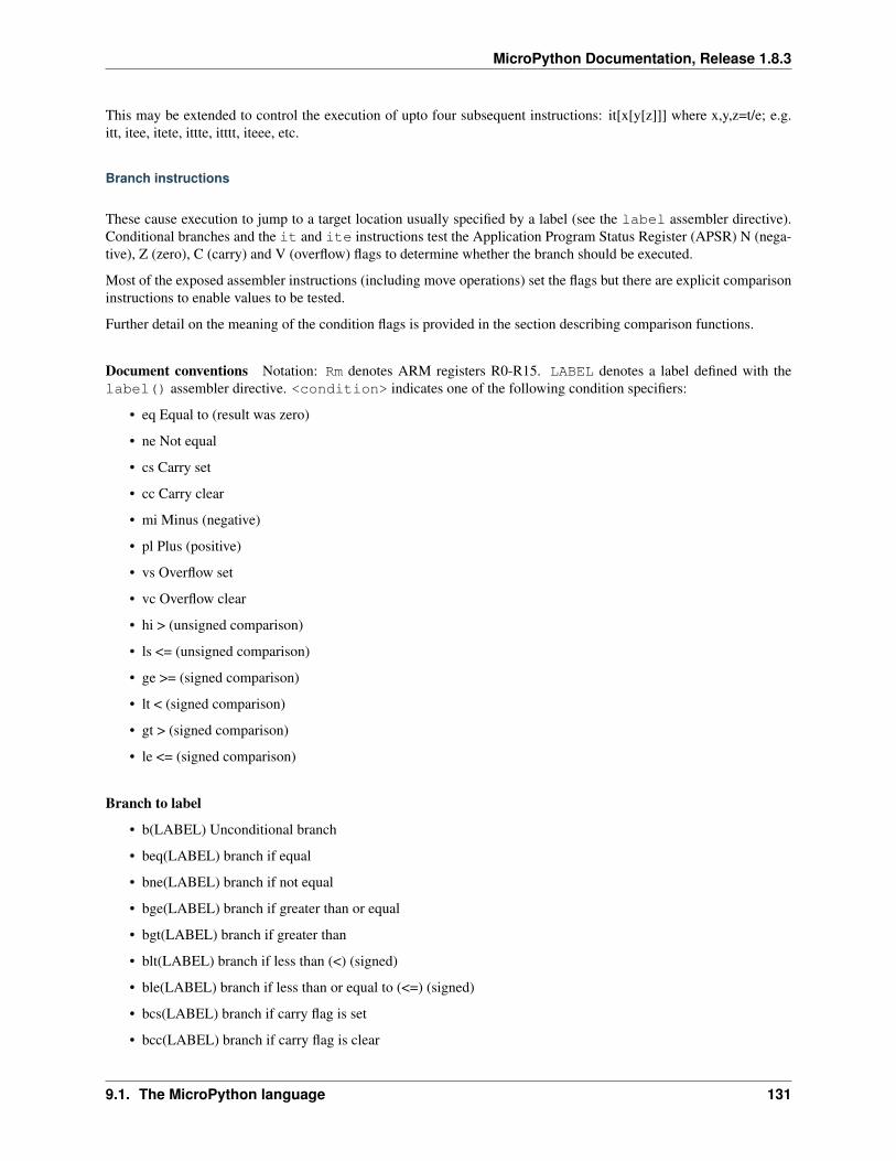
MicroPython Documentation, Release 1.8.3
This may be extended to control the execution of upto four subsequent instructions: it[x[y[z]]] where x,y,z=t/e; e.g.itt, itee, itete, ittte, itttt, iteee, etc.
Branch instructions
These cause execution to jump to a target location usually specified by a label (see the label assembler directive).Conditional branches and the it and ite instructions test the Application Program Status Register (APSR) N (nega-tive), Z (zero), C (carry) and V (overflow) flags to determine whether the branch should be executed.
Most of the exposed assembler instructions (including move operations) set the flags but there are explicit comparisoninstructions to enable values to be tested.
Further detail on the meaning of the condition flags is provided in the section describing comparison functions.
Document conventions Notation: Rm denotes ARM registers R0-R15. LABEL denotes a label defined with thelabel() assembler directive. <condition> indicates one of the following condition specifiers:
• eq Equal to (result was zero)
• ne Not equal
• cs Carry set
• cc Carry clear
• mi Minus (negative)
• pl Plus (positive)
• vs Overflow set
• vc Overflow clear
• hi > (unsigned comparison)
• ls <= (unsigned comparison)
• ge >= (signed comparison)
• lt < (signed comparison)
• gt > (signed comparison)
• le <= (signed comparison)
Branch to label
• b(LABEL) Unconditional branch
• beq(LABEL) branch if equal
• bne(LABEL) branch if not equal
• bge(LABEL) branch if greater than or equal
• bgt(LABEL) branch if greater than
• blt(LABEL) branch if less than (<) (signed)
• ble(LABEL) branch if less than or equal to (<=) (signed)
• bcs(LABEL) branch if carry flag is set
• bcc(LABEL) branch if carry flag is clear
9.1. The MicroPython language 131
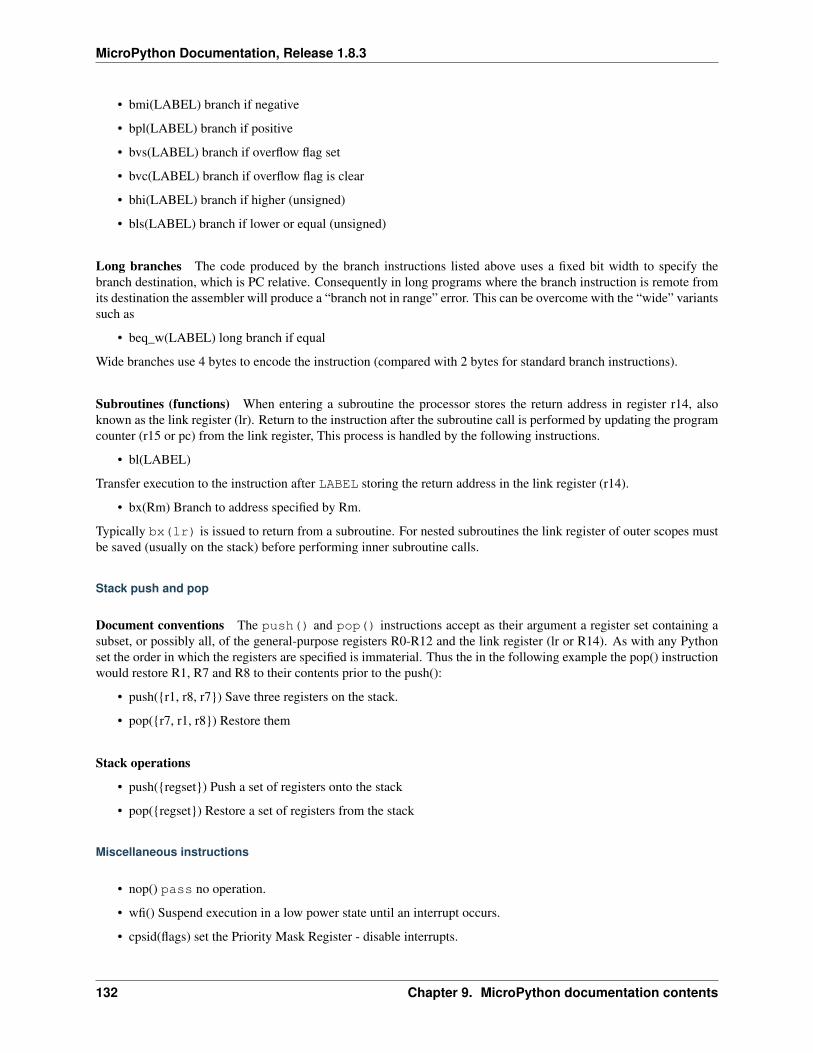
MicroPython Documentation, Release 1.8.3
• bmi(LABEL) branch if negative
• bpl(LABEL) branch if positive
• bvs(LABEL) branch if overflow flag set
• bvc(LABEL) branch if overflow flag is clear
• bhi(LABEL) branch if higher (unsigned)
• bls(LABEL) branch if lower or equal (unsigned)
Long branches The code produced by the branch instructions listed above uses a fixed bit width to specify thebranch destination, which is PC relative. Consequently in long programs where the branch instruction is remote fromits destination the assembler will produce a “branch not in range” error. This can be overcome with the “wide” variantssuch as
• beq_w(LABEL) long branch if equal
Wide branches use 4 bytes to encode the instruction (compared with 2 bytes for standard branch instructions).
Subroutines (functions) When entering a subroutine the processor stores the return address in register r14, alsoknown as the link register (lr). Return to the instruction after the subroutine call is performed by updating the programcounter (r15 or pc) from the link register, This process is handled by the following instructions.
• bl(LABEL)
Transfer execution to the instruction after LABEL storing the return address in the link register (r14).
• bx(Rm) Branch to address specified by Rm.
Typically bx(lr) is issued to return from a subroutine. For nested subroutines the link register of outer scopes mustbe saved (usually on the stack) before performing inner subroutine calls.
Stack push and pop
Document conventions The push() and pop() instructions accept as their argument a register set containing asubset, or possibly all, of the general-purpose registers R0-R12 and the link register (lr or R14). As with any Pythonset the order in which the registers are specified is immaterial. Thus the in the following example the pop() instructionwould restore R1, R7 and R8 to their contents prior to the push():
• push({r1, r8, r7}) Save three registers on the stack.
• pop({r7, r1, r8}) Restore them
Stack operations
• push({regset}) Push a set of registers onto the stack
• pop({regset}) Restore a set of registers from the stack
Miscellaneous instructions
• nop() pass no operation.
• wfi() Suspend execution in a low power state until an interrupt occurs.
• cpsid(flags) set the Priority Mask Register - disable interrupts.
132 Chapter 9. MicroPython documentation contents
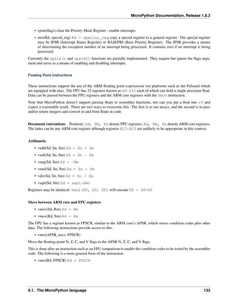
MicroPython Documentation, Release 1.8.3
• cpsie(flags) clear the Priority Mask Register - enable interrupts.
• mrs(Rd, special_reg) Rd = special_reg copy a special register to a general register. The special registermay be IPSR (Interrupt Status Register) or BASEPRI (Base Priority Register). The IPSR provides a meansof determining the exception number of an interrupt being processed. It contains zero if no interrupt is beingprocessed.
Currently the cpsie() and cpsid() functions are partially implemented. They require but ignore the flags argu-ment and serve as a means of enabling and disabling interrupts.
Floating Point instructions
These instructions support the use of the ARM floating point coprocessor (on platforms such as the Pyboard whichare equipped with one). The FPU has 32 registers known as s0-s31 each of which can hold a single precision float.Data can be passed between the FPU registers and the ARM core registers with the vmov instruction.
Note that MicroPython doesn’t support passing floats to assembler functions, nor can you put a float into r0 andexpect a reasonable result. There are two ways to overcome this. The first is to use arrays, and the second is to passand/or return integers and convert to and from floats in code.
Document conventions Notation: Sd, Sm, Sn denote FPU registers, Rd, Rm, Rn denote ARM core registers.The latter can be any ARM core register although registers R13-R15 are unlikely to be appropriate in this context.
Arithmetic
• vadd(Sd, Sn, Sm) Sd = Sn + Sm
• vsub(Sd, Sn, Sm) Sd = Sn - Sm
• vneg(Sd, Sm) Sd = -Sm
• vmul(Sd, Sn, Sm) Sd = Sn * Sm
• vdiv(Sd, Sn, Sm) Sd = Sn / Sm
• vsqrt(Sd, Sm) Sd = sqrt(Sm)
Registers may be identical: vmul(S0, S0, S0) will execute S0 = S0*S0
Move between ARM core and FPU registers
• vmov(Sd, Rm) Sd = Rm
• vmov(Rd, Sm) Rd = Sm
The FPU has a register known as FPSCR, similar to the ARM core’s APSR, which stores condition codes plus otherdata. The following instructions provide access to this.
• vmrs(APSR_nzcv, FPSCR)
Move the floating-point N, Z, C, and V flags to the APSR N, Z, C, and V flags.
This is done after an instruction such as an FPU comparison to enable the condition codes to be tested by the assemblercode. The following is a more general form of the instruction.
• vmrs(Rd, FPSCR) Rd = FPSCR
9.1. The MicroPython language 133
MicroPython Documentation, Release 1.8.3
Move between FPU register and memory
• vldr(Sd, [Rn, offset]) Sd = [Rn + offset]
• vstr(Sd, [Rn, offset]) [Rn + offset] = Sd
Where [Rn + offset] denotes the memory address obtained by adding Rn to the offset. This is specified in bytes.Since each float value occupies a 32 bit word, when accessing arrays of floats the offset must always be a multiple offour bytes.
Data Comparison
• vcmp(Sd, Sm)
Compare the values in Sd and Sm and set the FPU N, Z, C, and V flags. This would normally be followed byvmrs(APSR_nzcv, FPSCR) to enable the results to be tested.
Convert between integer and float
• vcvt_f32_s32(Sd, Sm) Sd = float(Sm)
• vcvt_s32_f32(Sd, Sm) Sd = int(Sm)
Assembler Directives
Labels
• label(INNER1)
This defines a label for use in a branch instruction. Thus elsewhere in the code a b(INNER1) will cause execution tocontinue with the instruction after the label directive.
Defining inline data The following assembler directives facilitate embedding data in an assembler code block.
• data(size, d0, d1 .. dn)
The data directive creates n array of data values in memory. The first argument specifies the size in bytes of thesubsequent arguments. Hence the first statement below will cause the assembler to put three bytes (with values 2, 3and 4) into consecutive memory locations while the second will cause it to emit two four byte words.
data(1, 2, 3, 4)data(4, 2, 100000)
Data values longer than a single byte are stored in memory in little-endian format.
• align(nBytes)
Align the following instruction to an nBytes value. ARM Thumb-2 instructions must be two byte aligned, hence it’sadvisable to issue align(2) after data directives and prior to any subsequent code. This ensures that the code willrun irrespective of the size of the data array.
Usage examples
These sections provide further code examples and hints on the use of the assembler.
134 Chapter 9. MicroPython documentation contents
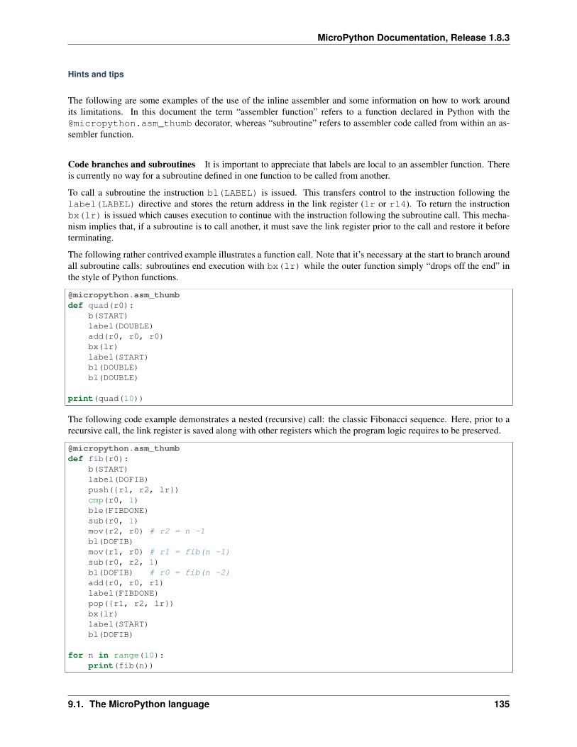
MicroPython Documentation, Release 1.8.3
Hints and tips
The following are some examples of the use of the inline assembler and some information on how to work aroundits limitations. In this document the term “assembler function” refers to a function declared in Python with [email protected]_thumb decorator, whereas “subroutine” refers to assembler code called from within an as-sembler function.
Code branches and subroutines It is important to appreciate that labels are local to an assembler function. Thereis currently no way for a subroutine defined in one function to be called from another.
To call a subroutine the instruction bl(LABEL) is issued. This transfers control to the instruction following thelabel(LABEL) directive and stores the return address in the link register (lr or r14). To return the instructionbx(lr) is issued which causes execution to continue with the instruction following the subroutine call. This mecha-nism implies that, if a subroutine is to call another, it must save the link register prior to the call and restore it beforeterminating.
The following rather contrived example illustrates a function call. Note that it’s necessary at the start to branch aroundall subroutine calls: subroutines end execution with bx(lr) while the outer function simply “drops off the end” inthe style of Python functions.
@micropython.asm_thumbdef quad(r0):
b(START)label(DOUBLE)add(r0, r0, r0)bx(lr)label(START)bl(DOUBLE)bl(DOUBLE)
print(quad(10))
The following code example demonstrates a nested (recursive) call: the classic Fibonacci sequence. Here, prior to arecursive call, the link register is saved along with other registers which the program logic requires to be preserved.
@micropython.asm_thumbdef fib(r0):
b(START)label(DOFIB)push({r1, r2, lr})cmp(r0, 1)ble(FIBDONE)sub(r0, 1)mov(r2, r0) # r2 = n -1bl(DOFIB)mov(r1, r0) # r1 = fib(n -1)sub(r0, r2, 1)bl(DOFIB) # r0 = fib(n -2)add(r0, r0, r1)label(FIBDONE)pop({r1, r2, lr})bx(lr)label(START)bl(DOFIB)
for n in range(10):print(fib(n))
9.1. The MicroPython language 135

MicroPython Documentation, Release 1.8.3
Argument passing and return The tutorial details the fact that assembler functions can support from zero to threearguments, which must (if used) be named r0, r1 and r2. When the code executes the registers will be initialised tothose values.
The data types which can be passed in this way are integers and memory addresses. With current firmware all possible32 bit values may be passed and returned. If the return value may have the most significant bit set a Python typehint should be employed to enable MicroPython to determine whether the value should be interpreted as a signed orunsigned integer: types are int or uint.
@micropython.asm_thumbdef uadd(r0, r1) -> uint:
add(r0, r0, r1)
hex(uadd(0x40000000,0x40000000)) will return 0x80000000, demonstrating the passing and return of in-tegers where bits 30 and 31 differ.
The limitations on the number of arguments and return values can be overcome by means of the array module whichenables any number of values of any type to be accessed.
Multiple arguments If a Python array of integers is passed as an argument to an assembler function, the functionwill receive the address of a contiguous set of integers. Thus multiple arguments can be passed as elements of a singlearray. Similarly a function can return multiple values by assigning them to array elements. Assembler functions haveno means of determining the length of an array: this will need to be passed to the function.
This use of arrays can be extended to enable more than three arrays to be used. This is done using indirection: theuctypes module supports addressof() which will return the address of an array passed as its argument. Thusyou can populate an integer array with the addresses of other arrays:
from uctypes import [email protected]_thumbdef getindirect(r0):
ldr(r0, [r0, 0]) # Address of array loaded from passed arrayldr(r0, [r0, 4]) # Return element 1 of indirect array (24)
def testindirect():a = array.array('i',[23, 24])b = array.array('i',[0,0])b[0] = addressof(a)print(getindirect(b))
Non-integer data types These may be handled by means of arrays of the appropriate data type. For example, singleprecision floating point data may be processed as follows. This code example takes an array of floats and replaces itscontents with their squares.
from array import array
@micropython.asm_thumbdef square(r0, r1):
label(LOOP)vldr(s0, [r0, 0])vmul(s0, s0, s0)vstr(s0, [r0, 0])add(r0, 4)sub(r1, 1)bgt(LOOP)
a = array('f', (x for x in range(10)))
136 Chapter 9. MicroPython documentation contents
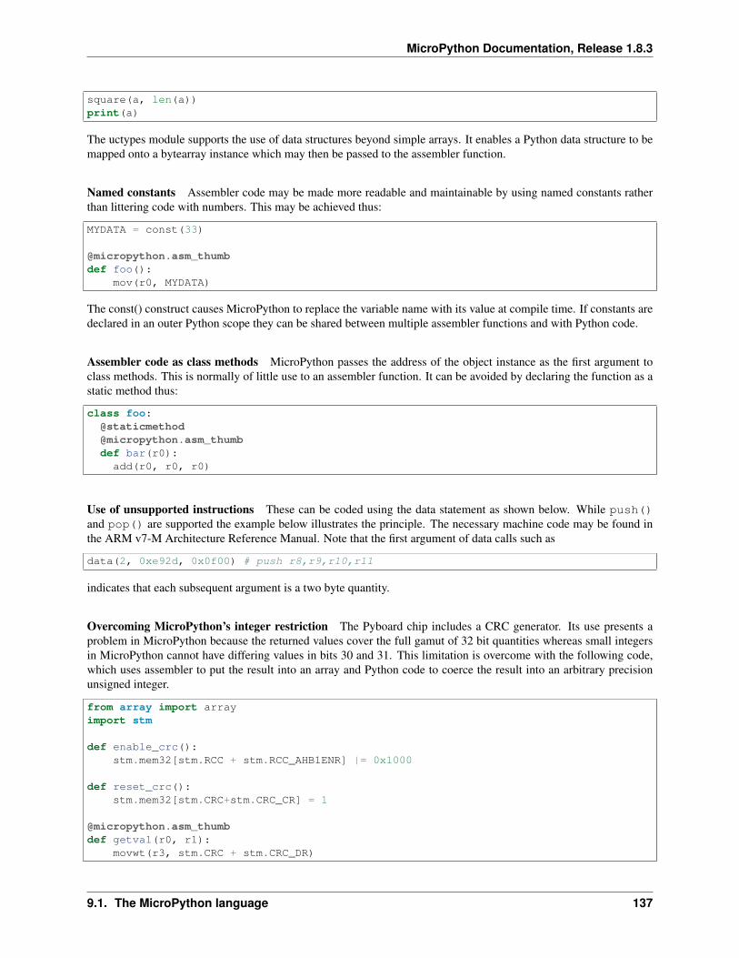
MicroPython Documentation, Release 1.8.3
square(a, len(a))print(a)
The uctypes module supports the use of data structures beyond simple arrays. It enables a Python data structure to bemapped onto a bytearray instance which may then be passed to the assembler function.
Named constants Assembler code may be made more readable and maintainable by using named constants ratherthan littering code with numbers. This may be achieved thus:
MYDATA = const(33)
@micropython.asm_thumbdef foo():
mov(r0, MYDATA)
The const() construct causes MicroPython to replace the variable name with its value at compile time. If constants aredeclared in an outer Python scope they can be shared between multiple assembler functions and with Python code.
Assembler code as class methods MicroPython passes the address of the object instance as the first argument toclass methods. This is normally of little use to an assembler function. It can be avoided by declaring the function as astatic method thus:
class foo:@[email protected]_thumbdef bar(r0):add(r0, r0, r0)
Use of unsupported instructions These can be coded using the data statement as shown below. While push()and pop() are supported the example below illustrates the principle. The necessary machine code may be found inthe ARM v7-M Architecture Reference Manual. Note that the first argument of data calls such as
data(2, 0xe92d, 0x0f00) # push r8,r9,r10,r11
indicates that each subsequent argument is a two byte quantity.
Overcoming MicroPython’s integer restriction The Pyboard chip includes a CRC generator. Its use presents aproblem in MicroPython because the returned values cover the full gamut of 32 bit quantities whereas small integersin MicroPython cannot have differing values in bits 30 and 31. This limitation is overcome with the following code,which uses assembler to put the result into an array and Python code to coerce the result into an arbitrary precisionunsigned integer.
from array import arrayimport stm
def enable_crc():stm.mem32[stm.RCC + stm.RCC_AHB1ENR] |= 0x1000
def reset_crc():stm.mem32[stm.CRC+stm.CRC_CR] = 1
@micropython.asm_thumbdef getval(r0, r1):
movwt(r3, stm.CRC + stm.CRC_DR)
9.1. The MicroPython language 137
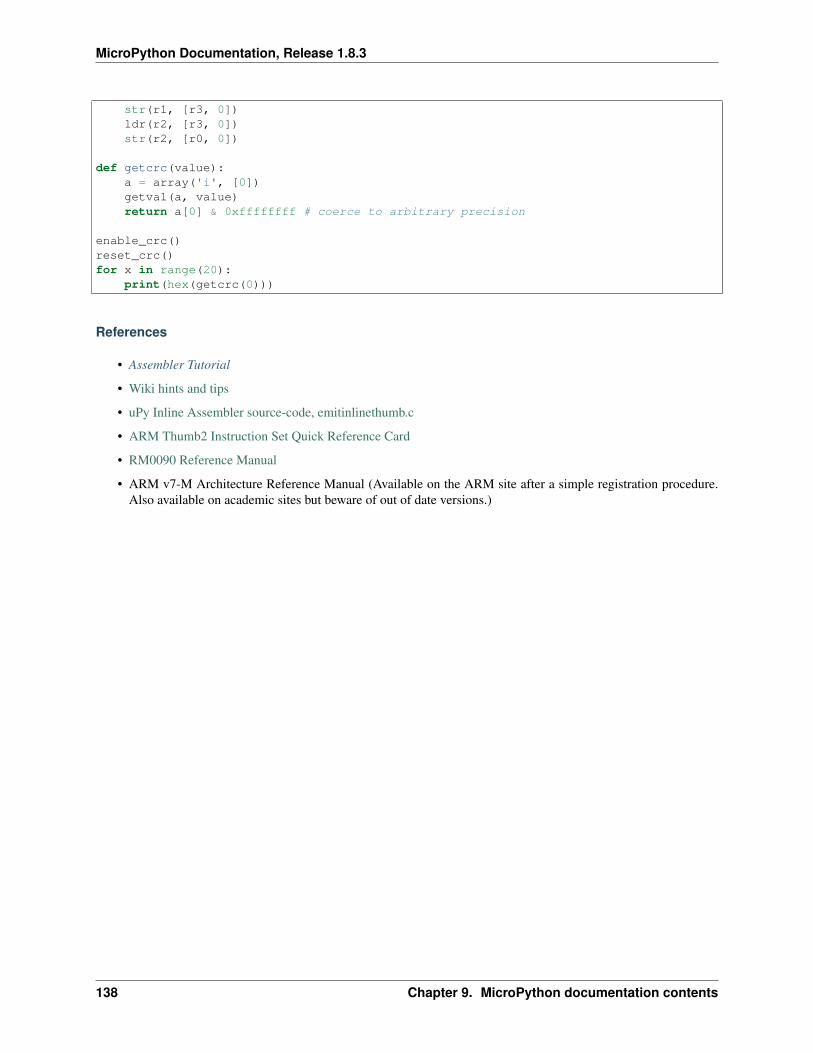
MicroPython Documentation, Release 1.8.3
str(r1, [r3, 0])ldr(r2, [r3, 0])str(r2, [r0, 0])
def getcrc(value):a = array('i', [0])getval(a, value)return a[0] & 0xffffffff # coerce to arbitrary precision
enable_crc()reset_crc()for x in range(20):
print(hex(getcrc(0)))
References
• Assembler Tutorial
• Wiki hints and tips
• uPy Inline Assembler source-code, emitinlinethumb.c
• ARM Thumb2 Instruction Set Quick Reference Card
• RM0090 Reference Manual
• ARM v7-M Architecture Reference Manual (Available on the ARM site after a simple registration procedure.Also available on academic sites but beware of out of date versions.)
138 Chapter 9. MicroPython documentation contents
CHAPTER
TEN
INDICES AND TABLES
• genindex
• modindex
• search
139

MicroPython Documentation, Release 1.8.3
140 Chapter 10. Indices and tables
PYTHON MODULE INDEX
aarray, 37
ccmath, 40
ggc, 40
mmachine, 55math, 41micropython, 65
nnetwork, 66
ppyb, 71
sselect, 43sys, 44
uubinascii, 45ucollections, 46uctypes, 69uhashlib, 47uheapq, 47uio, 47ujson, 48uos, 48ure, 49usocket, 50ustruct, 53utime, 53uzlib, 55
141

MicroPython Documentation, Release 1.8.3
142 Python Module Index
INDEX
Symbols__call__() (machine.Pin method), 60__call__() (pyb.Switch method), 96__str__() (pyb.Pin method), 89__str__() (pyb.pinaf method), 91
Aa2b_base64() (in module ubinascii), 46abs() (built-in function), 38accept() (usocket.socket method), 51acos() (in module math), 41acosh() (in module math), 41ADC (class in machine), 57adcchannel() (in module machine), 57addressof() (in module uctypes), 70af() (pyb.Pin method), 89af_list() (pyb.Pin method), 90alarm() (machine.RTC method), 61alarm_left() (machine.RTC method), 61all() (built-in function), 38alloc_emergency_exception_buf() (in module micropy-
thon), 66alt_list() (machine.Pin method), 60angle() (pyb.Servo method), 93any() (built-in function), 38any() (machine.UART method), 64any() (pyb.CAN method), 79any() (pyb.UART method), 101any() (pyb.USB_VCP method), 103append() (array.array.array method), 38argv (in module sys), 44array (module), 37array.array (class in array), 38asin() (in module math), 41asinh() (in module math), 41atan() (in module math), 41atan2() (in module math), 41atanh() (in module math), 41
Bb2a_base64() (in module ubinascii), 46BIG_ENDIAN (in module uctypes), 70
bin() (built-in function), 38bind() (usocket.socket method), 51bool (built-in class), 38bootloader() (in module pyb), 72bytearray (built-in class), 38bytearray_at() (in module uctypes), 70byteorder (in module sys), 44bytes (built-in class), 38bytes_at() (in module uctypes), 70BytesIO (class in uio), 48
Ccalcsize() (in module ustruct), 53calibration() (pyb.RTC method), 92calibration() (pyb.Servo method), 93callable() (built-in function), 38callback() (pyb.Switch method), 96callback() (pyb.Timer method), 97callback() (pyb.timerchannel method), 99CAN.LIST16 (in module pyb), 80CAN.LIST32 (in module pyb), 80CAN.LOOPBACK (in module pyb), 80CAN.MASK16 (in module pyb), 80CAN.MASK32 (in module pyb), 80CAN.NORMAL (in module pyb), 80CAN.SILENT (in module pyb), 80CAN.SILENT_LOOPBACK (in module pyb), 80cancel() (machine.RTC method), 61capture() (pyb.timerchannel method), 99CC3K (class in network), 67CC3K.WEP (in module network), 67CC3K.WPA (in module network), 67CC3K.WPA2 (in module network), 67ceil() (in module math), 41channel() (machine.ADC method), 57channel() (pyb.Timer method), 97chdir() (in module uos), 48chr() (built-in function), 38classmethod() (built-in function), 38clearfilter() (pyb.CAN method), 79close() (pyb.USB_VCP method), 103close() (usocket.socket method), 51
143
MicroPython Documentation, Release 1.8.3
cmath (module), 40collect() (in module gc), 40command() (pyb.LCD method), 86compare() (pyb.timerchannel method), 99compile() (built-in function), 38compile() (in module ure), 50complex (built-in class), 38connect() (network.cc3k method), 67connect() (usocket.socket method), 51contrast() (pyb.LCD method), 87copysign() (in module math), 41cos() (in module cmath), 40cos() (in module math), 41cosh() (in module math), 41counter() (pyb.Timer method), 99
Ddatetime() (pyb.RTC method), 91DEBUG (in module ure), 50debug() (pyb.Pin class method), 89decompress() (in module uzlib), 55deepsleep() (in module machine), 56degrees() (in module math), 41deinit() (machine.ADC method), 57deinit() (machine.adcchannel method), 58deinit() (machine.I2C method), 58deinit() (machine.RTC method), 61deinit() (machine.SD method), 62deinit() (machine.SPI method), 62deinit() (machine.Timer method), 63deinit() (machine.UART method), 64deinit() (pyb.CAN method), 78deinit() (pyb.DAC method), 81deinit() (pyb.I2C method), 85deinit() (pyb.SPI method), 94deinit() (pyb.Timer method), 97deinit() (pyb.UART method), 101delay() (in module pyb), 72dict (built-in class), 38dict() (pyb.Pin class method), 89digest() (uhashlib.hash method), 47dir() (built-in function), 38disable() (in module gc), 40disable() (pyb.ExtInt method), 83disable_irq() (in module machine), 55disable_irq() (in module pyb), 73disconnect() (network.cc3k method), 67divmod() (built-in function), 38dumps() (in module ujson), 48
Ee (in module cmath), 40e (in module math), 43elapsed_micros() (in module pyb), 72
elapsed_millis() (in module pyb), 72enable() (in module gc), 40enable() (pyb.ExtInt method), 83enable_irq() (in module machine), 55enable_irq() (in module pyb), 73enumerate() (built-in function), 38erf() (in module math), 41erfc() (in module math), 41eval() (built-in function), 38exec() (built-in function), 38exit() (in module sys), 44exp() (in module cmath), 40exp() (in module math), 41expm1() (in module math), 41extend() (array.array.array method), 38ExtInt.IRQ_FALLING (in module pyb), 83ExtInt.IRQ_RISING (in module pyb), 83ExtInt.IRQ_RISING_FALLING (in module pyb), 83
Ffabs() (in module math), 42feed() (machine.wdt method), 65FileIO (class in uio), 48fill() (pyb.LCD method), 87filter() (built-in function), 38filtered_xyz() (pyb.Accel method), 75float (built-in class), 38floor() (in module math), 42fmod() (in module math), 42freq() (in module machine), 56freq() (in module pyb), 73freq() (pyb.Timer method), 99frexp() (in module math), 42frozenset (built-in class), 38
Ggamma() (in module math), 42gc (module), 40get() (pyb.LCD method), 87getattr() (built-in function), 38getcwd() (in module uos), 48getvalue() (uio.BytesIO method), 48globals() (built-in function), 38gpio() (pyb.Pin method), 90group() (ure.match method), 50
Hhard_reset() (in module pyb), 72hasattr() (built-in function), 38hash() (built-in function), 38have_cdc() (in module pyb), 74heapify() (in module uheapq), 47heappop() (in module uheapq), 47heappush() (in module uheapq), 47
144 Index
MicroPython Documentation, Release 1.8.3
hex() (built-in function), 38hexdigest() (uhashlib.hash method), 47hexlify() (in module ubinascii), 45hid() (in module pyb), 74
II2C.MASTER (in module machine), 59I2C.MASTER (in module pyb), 86I2C.SLAVE (in module pyb), 86id() (built-in function), 38idle() (in module machine), 56ifconfig() (network.cc3k method), 67ifconfig() (network.wiznet5k method), 68implementation (in module sys), 44index() (pyb.pinaf method), 91info() (in module pyb), 74info() (pyb.RTC method), 92init() (machine.ADC method), 57init() (machine.adcchannel method), 58init() (machine.RTC method), 61init() (machine.SD method), 62init() (machine.SPI method), 62init() (pyb.CAN method), 78init() (pyb.DAC method), 81init() (pyb.I2C method), 85init() (pyb.Pin method), 89init() (pyb.SPI method), 94init() (pyb.Timer method), 96init() (pyb.UART method), 101initfilterbanks() (pyb.CAN class method), 78input() (built-in function), 39int (built-in class), 39intensity() (pyb.LED method), 87irq() (machine.RTC method), 61is_ready() (pyb.I2C method), 85isconnected() (network.cc3k method), 67isconnected() (pyb.USB_VCP method), 103isfinite() (in module math), 42isinf() (in module math), 42isinstance() (built-in function), 39isnan() (in module math), 42issubclass() (built-in function), 39iter() (built-in function), 39
Lldexp() (in module math), 42len() (built-in function), 39lgamma() (in module math), 42light() (pyb.LCD method), 87line() (pyb.ExtInt method), 83list (built-in class), 39listdir() (in module uos), 49listen() (usocket.socket method), 51LITTLE_ENDIAN (in module uctypes), 70
loads() (in module ujson), 48locals() (built-in function), 39localtime() (in module utime), 54log() (in module cmath), 40log() (in module math), 42log10() (in module cmath), 40log10() (in module math), 42log2() (in module math), 42
Mmachine (module), 55machine.DEEPSLEEP (in module machine), 56machine.DEEPSLEEP_RESET (in module machine), 56machine.HARD_RESET (in module machine), 56machine.IDLE (in module machine), 56machine.PIN_WAKE (in module machine), 57machine.POWER_ON (in module machine), 56machine.RTC_WAKE (in module machine), 57machine.SLEEP (in module machine), 56machine.SOFT_RESET (in module machine), 56machine.WDT_RESET (in module machine), 56machine.WLAN_WAKE (in module machine), 57main() (in module pyb), 74makefile() (usocket.socket method), 52map() (built-in function), 39mapper() (pyb.Pin class method), 89match() (in module ure), 50match() (ure.regex method), 50math (module), 41max() (built-in function), 39maxsize (in module sys), 44mem_alloc() (in module gc), 40mem_free() (in module gc), 41mem_info() (in module micropython), 65mem_read() (pyb.I2C method), 85mem_write() (pyb.I2C method), 85memoryview (built-in class), 39micropython (module), 65micros() (in module pyb), 72millis() (in module pyb), 72min() (built-in function), 39mkdir() (in module uos), 49mktime() (in module utime), 54mode() (pyb.Pin method), 90modf() (in module math), 42modify() (select.poll method), 43modules (in module sys), 45mount() (in module pyb), 74
Nname() (pyb.Pin method), 90name() (pyb.pinaf method), 91namedtuple() (in module ucollections), 46names() (pyb.Pin method), 90
Index 145
MicroPython Documentation, Release 1.8.3
NATIVE (in module uctypes), 70network (module), 66next() (built-in function), 39noise() (pyb.DAC method), 82now() (machine.RTC method), 61
Oobject (built-in class), 39oct() (built-in function), 39off() (pyb.LED method), 87on() (pyb.LED method), 87open() (built-in function), 39open() (in module uio), 47ord() (built-in function), 39OrderedDict() (in module ucollections), 46
Ppack() (in module ustruct), 53pack_into() (in module ustruct), 53patch_program() (network.cc3k method), 67patch_version() (network.cc3k method), 67path (in module sys), 45period() (pyb.Timer method), 99phase() (in module cmath), 40pi (in module cmath), 40pi (in module math), 43Pin (class in machine), 60pin() (pyb.Pin method), 90Pin.AF_OD (in module pyb), 90Pin.AF_PP (in module pyb), 90Pin.ALT (in module machine), 60Pin.ALT_OPEN_DRAIN (in module machine), 60Pin.ANALOG (in module pyb), 90Pin.board (class in machine), 60Pin.HIGH_POWER (in module machine), 60Pin.IN (in module machine), 60Pin.IN (in module pyb), 90Pin.IRQ_FALLING (in module machine), 60Pin.IRQ_HIGH_LEVEL (in module machine), 60Pin.IRQ_LOW_LEVEL (in module machine), 60Pin.IRQ_RISING (in module machine), 60Pin.LOW_POWER (in module machine), 60Pin.MED_POWER (in module machine), 60Pin.OPEN_DRAIN (in module machine), 60Pin.OUT (in module machine), 60Pin.OUT_OD (in module pyb), 90Pin.OUT_PP (in module pyb), 90Pin.PULL_DOWN (in module machine), 60Pin.PULL_DOWN (in module pyb), 90Pin.PULL_NONE (in module pyb), 90Pin.PULL_UP (in module machine), 60Pin.PULL_UP (in module pyb), 90pixel() (pyb.LCD method), 87platform (in module sys), 45
polar() (in module cmath), 40poll() (in module select), 43poll() (select.poll method), 44port() (pyb.Pin method), 90pow() (built-in function), 39pow() (in module math), 42prescaler() (pyb.Timer method), 99print() (built-in function), 39print_exception() (in module sys), 44property() (built-in function), 39pull() (pyb.Pin method), 90pulse_width() (pyb.Servo method), 93pulse_width() (pyb.timerchannel method), 99pulse_width_percent() (pyb.timerchannel method), 99pyb (module), 71pyb.Accel (class in pyb), 75pyb.ADC (class in pyb), 76pyb.CAN (class in pyb), 78pyb.DAC (class in pyb), 81pyb.ExtInt (class in pyb), 83pyb.I2C (class in pyb), 84pyb.LCD (class in pyb), 86pyb.LED (class in pyb), 87pyb.Pin (class in pyb), 89pyb.RTC (class in pyb), 91pyb.Servo (class in pyb), 93pyb.SPI (class in pyb), 94pyb.Switch (class in pyb), 95pyb.Timer (class in pyb), 96pyb.UART (class in pyb), 100pyb.USB_VCP (class in pyb), 103
Qqstr_info() (in module micropython), 65
Rradians() (in module math), 42range() (built-in function), 39read() (machine.SPI method), 62read() (machine.UART method), 64read() (pyb.ADC method), 76read() (pyb.UART method), 101read() (pyb.USB_VCP method), 103read() (usocket.socket method), 52read_timed() (pyb.ADC method), 76readall() (machine.UART method), 64readall() (pyb.UART method), 101readall() (pyb.USB_VCP method), 103readall() (usocket.socket method), 52readchar() (pyb.UART method), 101readfrom() (machine.I2C method), 59readfrom_into() (machine.I2C method), 59readfrom_mem() (machine.I2C method), 59readfrom_mem_into() (machine.I2C method), 59
146 Index
MicroPython Documentation, Release 1.8.3
readinto() (machine.I2C method), 58readinto() (machine.SPI method), 62readinto() (machine.UART method), 64readinto() (pyb.UART method), 101readinto() (pyb.USB_VCP method), 103readinto() (usocket.socket method), 52readline() (machine.UART method), 64readline() (pyb.UART method), 101readline() (pyb.USB_VCP method), 103readline() (usocket.socket method), 52readlines() (pyb.USB_VCP method), 103rect() (in module cmath), 40recv() (pyb.CAN method), 79recv() (pyb.I2C method), 85recv() (pyb.SPI method), 94recv() (pyb.USB_VCP method), 103recv() (usocket.socket method), 51recvfrom() (usocket.socket method), 52reg() (pyb.pinaf method), 91register() (select.poll method), 43regs() (network.wiznet5k method), 69regs() (pyb.ExtInt class method), 83remove() (in module uos), 49rename() (in module uos), 49repl_uart() (in module pyb), 74repr() (built-in function), 39reset() (in module machine), 55reset_cause() (in module machine), 55reversed() (built-in function), 39rmdir() (in module uos), 49rng() (in module pyb), 75round() (built-in function), 39RTC (class in machine), 61RTC.ALARM0 (in module machine), 61rxcallback() (pyb.CAN method), 80
Sscan() (machine.I2C method), 58scan() (pyb.I2C method), 86SD (class in machine), 62search() (in module ure), 50search() (ure.regex method), 50select (module), 43select() (in module select), 43send() (pyb.CAN method), 79send() (pyb.I2C method), 85send() (pyb.SPI method), 95send() (pyb.USB_VCP method), 104send() (usocket.socket method), 51send_recv() (pyb.SPI method), 95sendall() (usocket.socket method), 51sendbreak() (machine.UART method), 65sendbreak() (pyb.UART method), 102sendto() (usocket.socket method), 51
sep (in module uos), 49set (built-in class), 39setattr() (built-in function), 39setblocking() (usocket.socket method), 52setfilter() (pyb.CAN method), 78setinterrupt() (pyb.USB_VCP method), 103setsockopt() (usocket.socket method), 52settimeout() (usocket.socket method), 52show() (pyb.LCD method), 87sin() (in module cmath), 40sin() (in module math), 42sinh() (in module math), 42sizeof() (in module uctypes), 70sleep() (in module machine), 56sleep() (in module utime), 54sleep_ms() (in module utime), 54sleep_us() (in module utime), 54socket.AF_INET (in module usocket), 51socket.getaddrinfo() (in module usocket), 50socket.IPPROTO_TCP (in module usocket), 51socket.IPPROTO_UDP (in module usocket), 51socket.SOCK_DGRAM (in module usocket), 51socket.SOCK_STREAM (in module usocket), 51socket.socket() (in module usocket), 50sorted() (built-in function), 39source_freq() (pyb.Timer method), 99speed() (pyb.Servo method), 93SPI.LSB (in module pyb), 95SPI.MASTER (in module machine), 63SPI.MASTER (in module pyb), 95SPI.MSB (in module machine), 63SPI.MSB (in module pyb), 95SPI.SLAVE (in module pyb), 95split() (ure.regex method), 50sqrt() (in module cmath), 40sqrt() (in module math), 42standby() (in module pyb), 73start() (machine.I2C method), 58stat() (in module uos), 49staticmethod() (built-in function), 39stderr (in module sys), 45stdin (in module sys), 45stdout (in module sys), 45stop() (in module pyb), 73stop() (machine.I2C method), 58str (built-in class), 39StringIO (class in uio), 48struct (class in uctypes), 70sum() (built-in function), 39super() (built-in function), 39swint() (pyb.ExtInt method), 83sync() (in module pyb), 75sync() (in module uos), 49sys (module), 44
Index 147
MicroPython Documentation, Release 1.8.3
Ttan() (in module math), 42tanh() (in module math), 43text() (pyb.LCD method), 87TextIOWrapper (class in uio), 48ticks_cpu() (in module utime), 54ticks_diff() (in module utime), 54ticks_ms() (in module utime), 54ticks_us() (in module utime), 54tilt() (pyb.Accel method), 75time() (in module utime), 54time_pulse_us() (in module machine), 56Timer (class in machine), 63Timer.A (in module machine), 63Timer.B (in module machine), 63Timer.MATCH (in module machine), 63Timer.NEGATIVE (in module machine), 63Timer.ONE_SHOT (in module machine), 63Timer.PERIODIC (in module machine), 63Timer.POSITIVE (in module machine), 63Timer.PWM (in module machine), 63Timer.TIMEOUT (in module machine), 63toggle() (pyb.LED method), 87triangle() (pyb.DAC method), 82trunc() (in module math), 43tuple (built-in class), 39type() (built-in function), 39
UUART.CTS (in module pyb), 102UART.EVEN (in module machine), 65UART.ODD (in module machine), 65UART.RTS (in module pyb), 102UART.RX_ANY (in module machine), 65ubinascii (module), 45ucollections (module), 46uctypes (module), 69udelay() (in module pyb), 72uhashlib (module), 47uhashlib.sha256 (class in uhashlib), 47uheapq (module), 47uio (module), 47ujson (module), 48unhexlify() (in module ubinascii), 46unique_id() (in module machine), 56unique_id() (in module pyb), 75unpack() (in module ustruct), 53unpack_from() (in module ustruct), 53unregister() (select.poll method), 43uos (module), 48update() (uhashlib.hash method), 47urandom() (in module uos), 49ure (module), 49usocket (module), 50
ustruct (module), 53utime (module), 53uzlib (module), 55
Vvalue() (machine.adcchannel method), 57value() (machine.Pin method), 60value() (pyb.Pin method), 89version (in module sys), 45version_info (in module sys), 45
Wwakeup() (pyb.RTC method), 92WDT (class in machine), 65wfi() (in module pyb), 73WIZNET5K (class in network), 68write() (machine.I2C method), 58write() (machine.SPI method), 62write() (machine.UART method), 65write() (pyb.DAC method), 82write() (pyb.LCD method), 87write() (pyb.UART method), 102write() (pyb.USB_VCP method), 103write() (usocket.socket method), 52write_readinto() (machine.SPI method), 62write_timed() (pyb.DAC method), 82writechar() (pyb.UART method), 101writeto() (machine.I2C method), 59writeto_mem() (machine.I2C method), 59
Xx() (pyb.Accel method), 75
Yy() (pyb.Accel method), 75
Zz() (pyb.Accel method), 75zip() (built-in function), 39
148 Index