Embed Size (px)
Citation preview
NCR RealPOS 80c Release 1.1
Hardware User’s Guide
B005-0000-1359 Issue C

The product described in this book is a licensed product of NCR Corporation.
NCR is a registered trademark of NCR Corporation.
NCR RealPOS, NCR RealPrice, NCR RealScan, NCR EasyPoint and NCR FastLane are either registered trademarks or trademarks of NCR Corporation in the United States and/or other countries.
It is the policy of NCR Corporation (NCR) to improve products as new technology, components, software, and firmware become available. NCR, therefore, reserves the right to change specifications without prior notice.
All features, functions, and operations described herein may not be marketed by NCR in all parts of the world. In some instances, photographs are of equipment prototypes. Therefore, before using this document, consult with your NCR representative or NCR office for information that is applicable and current.
To maintain the quality of our publications, we need your comments on the accuracy, clarity, organization, and value of this book.
Address correspondence to:
Manager, Information Products NCR Corporation 2651 Satellite Blvd. Duluth, GA 30096
Copyright © 2002 By NCR Corporation Dayton, Ohio U.S.A. All Rights Reserved
i
Preface Audience This book is written for hardware installer/service personnel, system integrators, and field engineers.
Notice: This document is NCR proprietary information and is not to be disclosed or reproduced without consent.
Safety Warnings Servicing Caution: This product does not contain user serviceable parts. Servicing should only be performed by a qualified service technician.
Fuse Replacement Caution: For continued protection against risk of fire, replace only with the same type and ratings of fuse.
Attention: Pour prévenir et vous protéger contre un risque de feu, remplacer la fusible avec une autre fusible de même type, seulement.
Power Supply Cord Used as Disconnect Means Caution: The power supply cord is used as the main disconnect device. Ensure that the socket outlet is located/installed near the equipment and is easily accessible.
Attention: Le cordon d’alimentation est utilisé comme interrupteur général. La prise de courant doit être située ou installée å proximité du matériel et être facile d’accés.
ii
Lithium Battery Warning Caution: Danger of explosion if battery is incorrectly replaced. Replace only with the same or equivalent type as recommended by the manufacturer. The battery is battery is recyclable. At the end of its useful life, under various state and local laws it may be illegal to dispose of this battery into the municipal waste. Contact officials for recycling options or proper disposal.
Attention: Il y a danger d’explosion s’il y a remplacement incorrect de la batterie. Remplacer uniquement avec une batterie du même type ou d’un type recommandé par le constructeur. Mettre au rébut les batteries usagées conformément aux instructions du fabricant.
Battery Disposal (Switzerland) Refer to Annex 4.10 of SR814.013 for battery disposal.
IT Power System This product is suitable for connection to an IT power system with a phase-to-phase voltage not exceeding 240 V.
Peripheral Usage This terminal should only be used with peripheral devices that are certified by the appropriate safety agency for the country of installation (UL, CSA, TUV, VDE) or those which are recommended by NCR Corporation.
Caution: DO NOT connect or disconnect a printer, keyboard, or any other terminal-powered peripheral while the terminal is powered on. Doing so may result in peripheral or system damage.
Environmental Consciousness NCR is demonstrating its concern for the environment by designing an intelligent power management system into this terminal that operates efficiently whether the system is in a stand-alone or network environment.
iii
Grounding Instructions In the event of a malfunction or breakdown, grounding provides a path of least resistance for electric current to reduce the risk of electric shock. This product is equipped with an electric cord having an equipment-grounding conductor and a grounding plug. The plug must be plugged into a matching outlet that is properly installed and grounded in accordance with all local codes and ordinances. Do not modify the plug provided – if it will not fit the outlet, have the proper outlet installed by a qualified electrician. Improper connection of the equipment-grounding conductor can result in a risk of electric shock.
The conductor with insulation having an outer surface that is green with or without yellow stripes is the equipment-grounding conductor.
If repair or replacement of the electric cord or plug is necessary, do not connect the equipment-grounding conductor to a live terminal. Check with a qualified electrician or service personnel if the grounding instructions are not completely understood, or if you are in doubt as to whether the product is properly grounded.
Use only 3-wire extension cords that have 3-prong grounding plugs and 3-pole receptacles that accept the product’s plug. Repair or replace damaged or worn cords immediately.
iv
References
• NCR RealPOS 80c Hardware Service Guide (B005-0000-1358)
• NCR RealPOS 80c Site Preparation (B005-0000-1360)
• NCR RealPOS 80c Parts Identification Manual (B005-0000-1362)
• NCR 5932 USB Keyboard User’s Guide (B005-0000-1395)
• NCR 5942 12.1-Inch LCD Monitor User’s Guide (B005-0000-1394)
• NCR 5952 Wedge DynaKey User’s Guide (BD20-1370-A)
• NCR 5953 12.1-Inch DynaKey User’s Guide (B005-0000-1161)
• NCR 5964 12.1-Inch Touch LCD User’s Guide (B005-0000-1324)
• NCR 5972 2 x 20 Customer Display User’s Guide (B005-0000-1372)
• NCR 5973 International VFD Customer Display User’s Guide (B005-0000-1162)
• NCR 5982 5-Inch LCD Operator Display User’s Guide (BD20-1443-A)
• NCR 7158 Thermal Receipt and Impact Printer Owner’s Guide (B005-0000-1112)
• NCR 7167 Two-Station POS Printer Owner’s Guide (B005-0000-1406)
• NCR 7162 Printer Setup & User’s Guide (BD20-1453-A)
• NCR 7194 Thermal Receipt Printer Owner’s Guide (B005-0000-1097)
• NCR 7197 Receipt Printer Owner’s Guide (B005-0000-1409)
• NCR 5945 Electronic Payment Terminal User’s Guide (B005-0000-1104)
• NCR 5992 Signature Capture User’s Guide (B005-0000-1108)
v
Table of Contents
Chapter 1: Product Overview Introduction ...........................................................................................1-1
Configurations ................................................................................1-3 Additional Features........................................................................1-4
Serial Number/Model Number Label ...............................................1-5 Features ..................................................................................................1-6
Processor Board ..............................................................................1-6 4-Port USB Daughter Card............................................................1-7 6-Port USB Daughter Card w/ Audio.........................................1-7 ATX Riser Card...............................................................................1-8 Storage Media .................................................................................1-8 Power Supply..................................................................................1-8 Operating Systems .........................................................................1-9 UPS ...................................................................................................1-9
Power Management............................................................................1-10 Operator Displays...............................................................................1-15
5964 12.1-Inch Touch Screen .......................................................1-15 5942 12.1-Inch Color LCD............................................................1-17 7452-K309/K404 9-Inch Monochrome CRT..............................1-18 7452-K419 15-Inch Color CRT.....................................................1-18 NCR 5982 5-Inch LCD Display...................................................1-19
NCR 5953 12.1-Inch DynaKey...........................................................1-20 NCR 5952 Wedge DynaKey ..............................................................1-21 NCR 5932 Keyboards .........................................................................1-22
109-Key USB Keyboard ...............................................................1-22 115-Key PS/2 Big Ticket Keyboard............................................1-24 68-Key PS/2 POS Keyboard........................................................1-25
vi
NCR 5972 2x20 Remote Customer Display .....................................1-29 Features .....................................................................................1-29
NCR 5973 2x20 International VFD Customer Display ..................1-30 Features .....................................................................................1-30
Printers .................................................................................................1-31 NCR 7158 Printer..........................................................................1-31 NCR 7162 Printer..........................................................................1-32 NCR 7194 Printer..........................................................................1-32 NCR 7167 Printer..........................................................................1-33 NCR 7197 Printer..........................................................................1-33
System Configuration Diagrams ......................................................1-34
Chapter 2: Hardware Installation Introduction ...........................................................................................2-1
Installation Restrictions .................................................................2-1 Out-of-Box Hardware Installation......................................................2-2 Installing the Keyboard and Mouse ...................................................2-3
PS/2 Keyboard/Mouse Installation ............................................2-3 Dual Port Keyboard/Mouse Installation ....................................2-4 Mouse Installation Restriction ......................................................2-4
Installing the Transaction Printer .......................................................2-5 USB Installation ..............................................................................2-5 RS-232 Installation w/Power from Powered USB.....................2-6
Installing an NCR 5964 12.1-Inch Touch LCD ..................................2-7 Cable Connections..........................................................................2-7
DVI Connections ........................................................................2-8 RS-232 Connections ...................................................................2-9
Installing a 5942 12.1-Inch LCD Monitor.........................................2-10 Installing a 5953 DynaKey .................................................................2-11 Installing a 5952 DynaKey .................................................................2-12 Installing an NCR 5982 5-Inch Operator Display...........................2-13
vii
Installing the PCI LCD Board (5952-052)..............................2-13 Connecting the 5982 Display to the Terminal......................2-14
Installing a Secondary CRT Display (Dual Display)......................2-15 Installing the Hardware...............................................................2-15
Supported Configurations by Operating System ................2-16 Installing the Displays.............................................................2-17
Configuring the Software for Dual Display..............................2-19 Installing an NCR 5972 Remote Customer Display .......................2-20 Installing an NCR 5973 Remote Customer Display .......................2-22
Customer Display Cable Connections.......................................2-23
Chapter 3: Setup Introduction ...........................................................................................3-1
Entering Setup Using a Keyboard................................................3-1 How to Select Menu Options........................................................3-1 Restoring Factory Settings.............................................................3-2 Special DynaKey Keypad Mode...................................................3-2 Normal DynaKey Keypad Operating Mode ..............................3-4 Disabling Resources .......................................................................3-5 BIOS Default Values.......................................................................3-5 Main Menu ......................................................................................3-5 Advanced Menu .............................................................................3-8 Security Menu...............................................................................3-12 Power Menu ..................................................................................3-12 Boot Sequence ...............................................................................3-12
Chapter 4: Operating System Recovery Introduction ...........................................................................................4-1
Prerequisites ....................................................................................4-1 Connecting an External Backpack CD-ROM Drive...................4-2 Updating Procedures .....................................................................4-3
viii
Completing the OS Installation (Windows 2000) ..................4-6 Completing the OS Installation (Windows NT 4.0) ..............4-6 Completing the OS Installation (Windows EXe) ...................4-7 Completing the OS Installation (DOS)....................................4-7
Gold Disk Contents...............................................................................4-8 NCR 7456/58 Windows 2000 Operating System Recovery Software (LPIN: D370-0536-0100).................................................4-8
Installed Software: .....................................................................4-8 Software Drivers.........................................................................4-9 Special Settings ...........................................................................4-9 Recommendation .....................................................................4-10
NCR 7456/58 Windows NT 4.0 Operating System Recovery Software (LPIN: D370-0564-0100) ............................4-11
Installed Software: ...................................................................4-11 Software Drivers.......................................................................4-11 Special Settings .........................................................................4-12 Recommendation .....................................................................4-13
NCR RealPOS 80/80c Windows XPe Operating System Recovery Software (LPIN: D370-0570-0100) .............................4-14
Installed Software: ...................................................................4-14 Software Drivers.......................................................................4-14 Special Settings .........................................................................4-15 Recommendation .....................................................................4-15
OS Recovery from a Larger Disk Image ..........................................4-16
Chapter 5: BIOS Updating Procedures Introduction .........................................................................................5-18
Prerequisites ..................................................................................5-18 Connecting an External Backpack CD-ROM Drive.................5-19 Updating Procedures ...................................................................5-20
BIOS Crisis Recovery..........................................................................5-22
ix
Recovery Procedures....................................................................5-23 Cable/Connector Pin-Out Information ...........................................5-26
Chapter 6: Memory Dump General Memory Dump Information.................................................6-1
BIOS Requirements ........................................................................6-1 Disk Format.....................................................................................6-1 Supported Operating Systems......................................................6-3
Summary of Operating Systems ..............................................6-3 Prerequisites ....................................................................................6-4
Windows XP/2000.....................................................................6-4 Windows NT...............................................................................6-5
DOS Memory Dump Specifics ............................................................6-6 Dump Process Overview...............................................................6-6 Restrictions and Limitations .........................................................6-6 Performing the Memory Dump....................................................6-9
Configuring the Terminal .........................................................6-9 Dump Procedure........................................................................6-9 Tunes/Tones.............................................................................6-10 Moving the Files to Hard Disk and Reassembling..............6-12 Flow Chart.................................................................................6-13
Memory Dump Assembler..........................................................6-14
Appendix A: Retail Keyboard Key Layouts 68-Key Keyboard..................................................................................A-1
68-Key Keyboard Special Keypad Mode ...............................A-3 Special PC Setup Keypad Mode Activated (68-Key Keyboard)...................................................................................A-4
DynaKey .........................................................................................A-5 Special DynaKey Keypad Mode .............................................A-5 Normal DynaKey Keypad Operating Mode .........................A-7
x
5932 USB Keyboard.......................................................................A-8
Appendix B: Feature Kits
Appendix C: Cables Printer Cables ....................................................................................... C-1 Scanner Cables...................................................................................... C-3
7872 or 7875 Scanner/Scale (RS-232) .......................................... C-3 7892 Scanner (Powered RS-232) .................................................. C-3 7882 Scanner (Powered RS-232) .................................................. C-3 7837 Scanner (Powered RS-232) .................................................. C-3
Display Cables...................................................................................... C-4 VGA Display, Mono...................................................................... C-4 VGA Display, Color ...................................................................... C-4 CRT AC Power Extension ............................................................ C-4 5982 5-Inch LCD ............................................................................ C-5 5953 DynaKey ................................................................................ C-5 5953 DynaKey w/Insert ............................................................... C-5 Wedge Keyboard Y-Cable............................................................ C-6 5972 VFD Customer Display (Powered RS-232) ....................... C-6 DVI to DVI for 5964....................................................................... C-6 PS/2 - RS-232 & Power for 5964 .................................................. C-7 Wedge Keyboard Adapter ........................................................... C-7 12.1-Inch LCD Aux Power Cable ................................................ C-7
Cash Drawer Cables ............................................................................ C-8 Dual Cash Drawer, Y-Cable......................................................... C-8 Cash Drawer, Extension Cable .................................................... C-8
Communications Cable ....................................................................... C-8 Ethernet, 10/100BaseT.................................................................. C-8
Keyboard Cables .................................................................................. C-9 PS/2 Keyboard Extension ............................................................ C-9
xi
PS/2 Y-Cable.................................................................................. C-9 Signature Capture/Electronic Payment Terminal Cable ............. C-10
5945/5992 EPT (RS-232 w/Power) ........................................... C-10 5942 12V Power Cable................................................................. C-10
Power Cables ...................................................................................... C-11 AC Power...................................................................................... C-11
Appendix D: Memory Maps DOS Considerations ............................................................................D-2
Non-TAPS DOS Environment .....................................................D-3 TAPS DOS Environment ..............................................................D-3
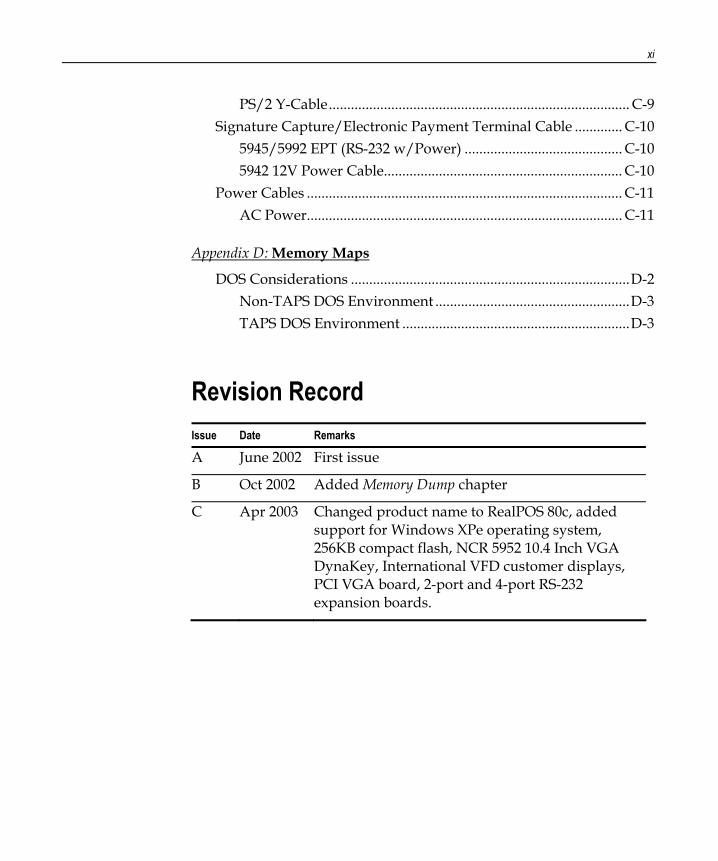
Revision Record Issue Date Remarks
A June 2002 First issue
B Oct 2002 Added Memory Dump chapter
C Apr 2003 Changed product name to RealPOS 80c, added support for Windows XPe operating system, 256KB compact flash, NCR 5952 10.4 Inch VGA DynaKey, International VFD customer displays, PCI VGA board, 2-port and 4-port RS-232 expansion boards.

xii
Radio Frequency Interference Statements
Federal Communications Commission (FCC) Information to User This equipment has been tested and found to comply with the limits for a Class A digital device, pursuant to Part 15 of FCC Rules. These limits are designed to provide reasonable protection against harmful interference when the equipment is operated in a commercial environment. This equipment generates, uses, and can radiate radio frequency energy and, if not installed and used in accordance with the instruction manual, may cause harmful interference to radio communications. Operation of this equipment in a residential area is likely to cause interference in which case the user will be required to correct the interference at his own expense.
NCR is not responsible for any radio or television interference caused by unauthorized modification of this equipment or the substitution or attachment of connecting cables and equipment other than those specified by NCR. The correction of interference caused by such unauthorized modification, substitution or attachment will be the responsibility of the user. The user is cautioned that changes or modifications not expressly approved by NCR may void the user’s authority to operate the equipment.
Canadian Department of Communications This Class A digital apparatus complies with Canadian ICES-003.
This digital apparatus does not exceed the Class A limits for radio noise emissions from digital apparatus set out in the Radio Interference Regulations of the Canadian Department of Communications.
Cet appareil numérique de la classe A est conforme à la norme NMB-003 du Canada.
Le présent appareil numérique n’émet pas de bruits radioélectriques dépassant les limites applicables aux appareils numériques de la classe A prescrites dans le règlement sur le brouillage radioélectriques édicté par le ministrère des Communications du Canada.

xiii
Voluntary Control Council for Interference (VCCI)
International Radio Frequency Interference Statement Warning: This is a Class A product. In a domestic environment this product may cause radio interference in which case the user may be required to take adequate measures.
xiv
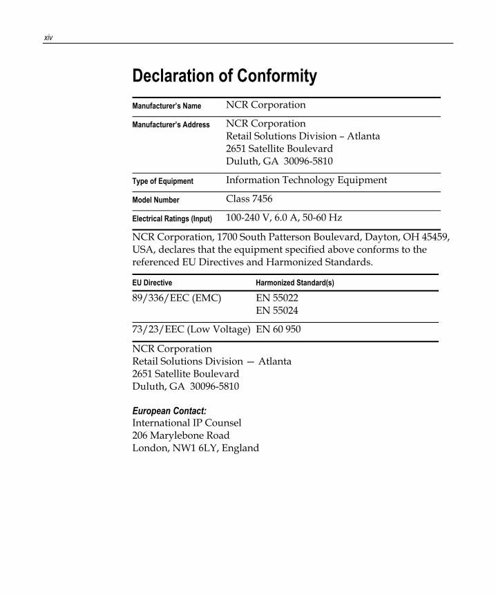
Declaration of Conformity Manufacturer’s Name NCR Corporation
Manufacturer’s Address NCR Corporation Retail Solutions Division – Atlanta 2651 Satellite Boulevard Duluth, GA 30096-5810
Type of Equipment Information Technology Equipment
Model Number Class 7456
Electrical Ratings (Input) 100-240 V, 6.0 A, 50-60 Hz
NCR Corporation, 1700 South Patterson Boulevard, Dayton, OH 45459, USA, declares that the equipment specified above conforms to the referenced EU Directives and Harmonized Standards.
EU Directive Harmonized Standard(s)
89/336/EEC (EMC) EN 55022 EN 55024
73/23/EEC (Low Voltage) EN 60 950
NCR Corporation Retail Solutions Division — Atlanta 2651 Satellite Boulevard Duluth, GA 30096-5810
European Contact: International IP Counsel 206 Marylebone Road London, NW1 6LY, England
Chapter 1: Product Overview
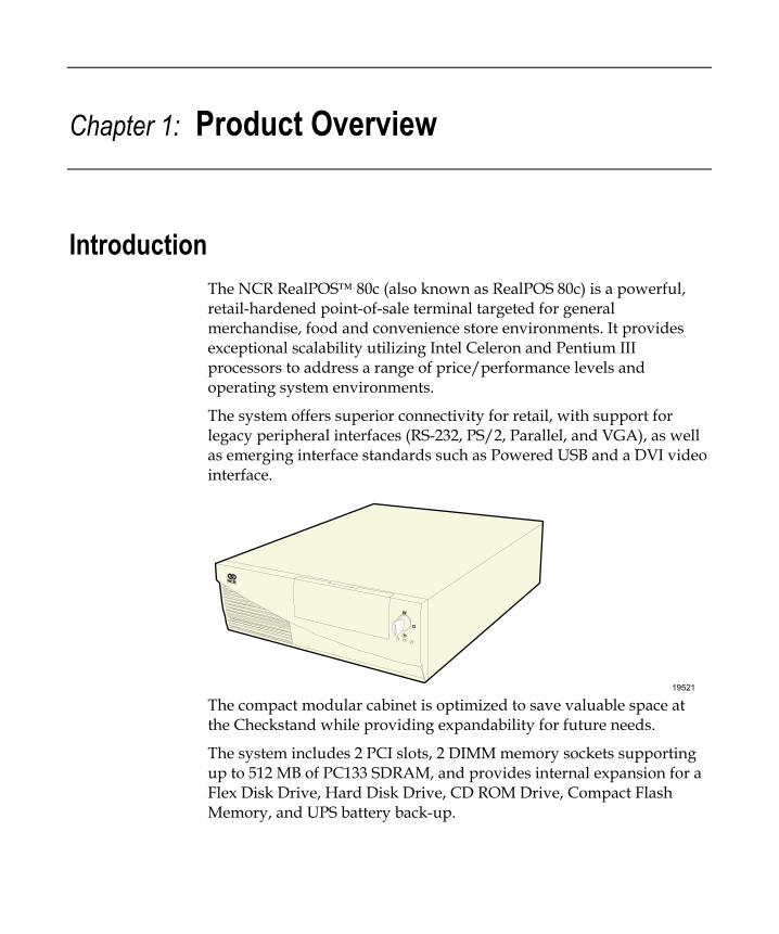
Introduction The NCR RealPOS 80c (also known as RealPOS 80c) is a powerful, retail-hardened point-of-sale terminal targeted for general merchandise, food and convenience store environments. It provides exceptional scalability utilizing Intel Celeron and Pentium III processors to address a range of price/performance levels and operating system environments.
The system offers superior connectivity for retail, with support for legacy peripheral interfaces (RS-232, PS/2, Parallel, and VGA), as well as emerging interface standards such as Powered USB and a DVI video interface.
19521 The compact modular cabinet is optimized to save valuable space at the Checkstand while providing expandability for future needs.
The system includes 2 PCI slots, 2 DIMM memory sockets supporting up to 512 MB of PC133 SDRAM, and provides internal expansion for a Flex Disk Drive, Hard Disk Drive, CD ROM Drive, Compact Flash Memory, and UPS battery back-up.
1-2 Chapter 1: Product Overview
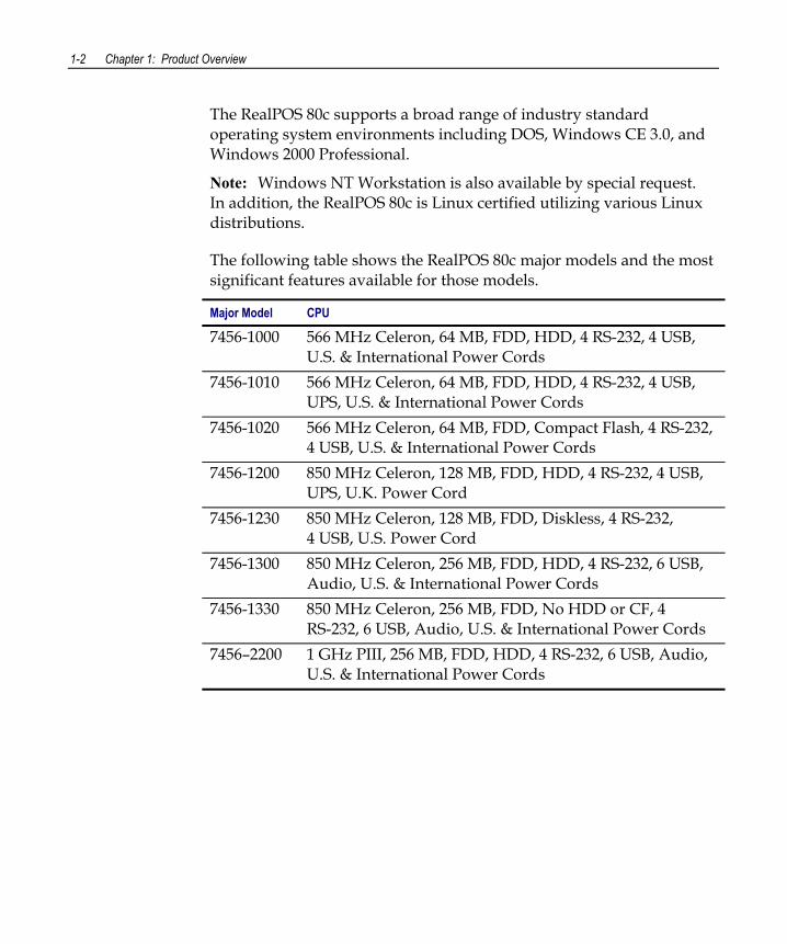
The RealPOS 80c supports a broad range of industry standard operating system environments including DOS, Windows CE 3.0, and Windows 2000 Professional.
Note: Windows NT Workstation is also available by special request. In addition, the RealPOS 80c is Linux certified utilizing various Linux distributions.
The following table shows the RealPOS 80c major models and the most significant features available for those models.
Major Model CPU
7456-1000 566 MHz Celeron, 64 MB, FDD, HDD, 4 RS-232, 4 USB, U.S. & International Power Cords
7456-1010 566 MHz Celeron, 64 MB, FDD, HDD, 4 RS-232, 4 USB, UPS, U.S. & International Power Cords
7456-1020 566 MHz Celeron, 64 MB, FDD, Compact Flash, 4 RS-232, 4 USB, U.S. & International Power Cords
7456-1200 850 MHz Celeron, 128 MB, FDD, HDD, 4 RS-232, 4 USB, UPS, U.K. Power Cord
7456-1230 850 MHz Celeron, 128 MB, FDD, Diskless, 4 RS-232, 4 USB, U.S. Power Cord
7456-1300 850 MHz Celeron, 256 MB, FDD, HDD, 4 RS-232, 6 USB, Audio, U.S. & International Power Cords
7456-1330 850 MHz Celeron, 256 MB, FDD, No HDD or CF, 4 RS-232, 6 USB, Audio, U.S. & International Power Cords
7456–2200 1 GHz PIII, 256 MB, FDD, HDD, 4 RS-232, 6 USB, Audio, U.S. & International Power Cords
Chapter 1: Product Overview 1-3
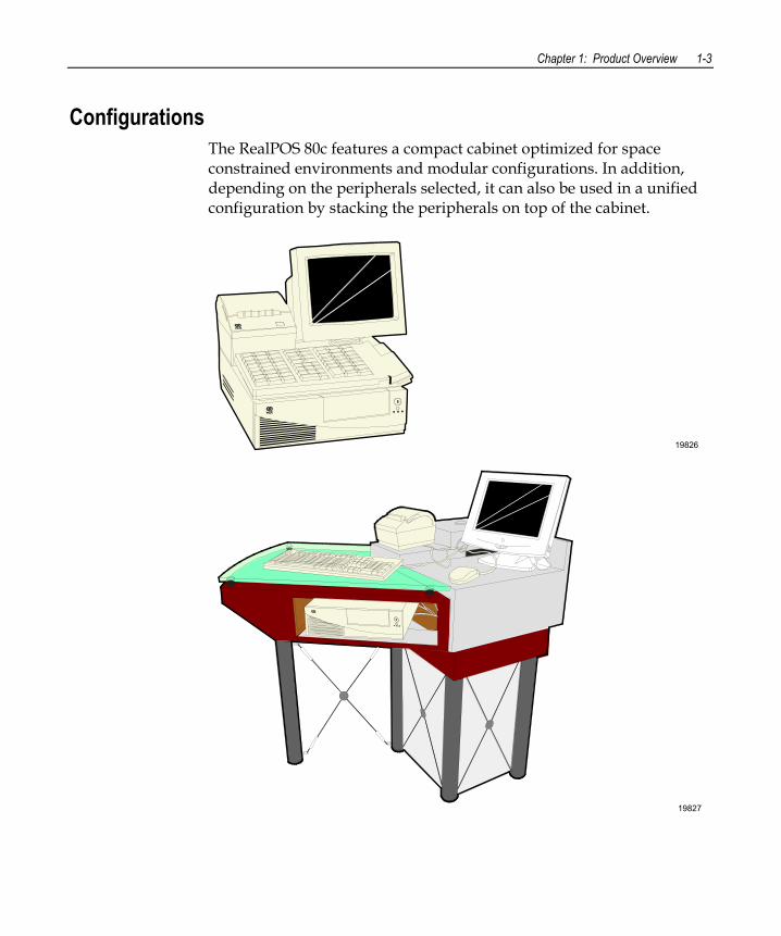
Configurations The RealPOS 80c features a compact cabinet optimized for space constrained environments and modular configurations. In addition, depending on the peripherals selected, it can also be used in a unified configuration by stacking the peripherals on top of the cabinet.
19826
19827
1-4 Chapter 1: Product Overview
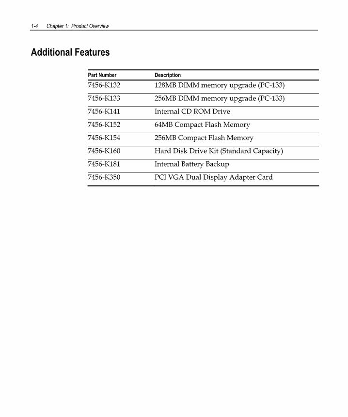
Additional Features
Part Number Description
7456-K132 128MB DIMM memory upgrade (PC-133)
7456-K133 256MB DIMM memory upgrade (PC-133)
7456-K141 Internal CD ROM Drive
7456-K152 64MB Compact Flash Memory
7456-K154 256MB Compact Flash Memory
7456-K160 Hard Disk Drive Kit (Standard Capacity)
7456-K181 Internal Battery Backup
7456-K350 PCI VGA Dual Display Adapter Card
Chapter 1: Product Overview 1-5
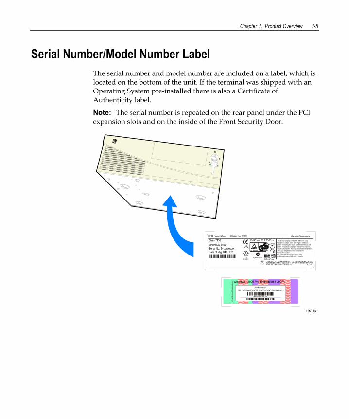
Serial Number/Model Number Label The serial number and model number are included on a label, which is located on the bottom of the unit. If the terminal was shipped with an Operating System pre-installed there is also a Certificate of Authenticity label.
Note: The serial number is repeated on the rear panel under the PCI expansion slots and on the inside of the Front Security Door.
19713
Model No: xxxxSerial No: 54-xxxxxxxxDate of Mfg. 04/10/02
Class 7456NCR Corporation Atlanta, GA 30096 Made in Singapore
This device complies with Part 15 of the FCC rules.Operation is subject to the following two conditions:(1) this device may not cause harmful interference, and(2) this device must accept any ionterference received, including interference that may cause indesired operation.This Class A digital apparatus complies withCanadian ICES-003Get Appareli numeriqe de la classe A estconformo a la normo NMB-003 ju Canada
ACN 000 003 592NO.437
100-240 Vac 6.0 A 50-60 Hz
I. T. E.E152553
Windows 2000 Pro Embedded 1-2 CPU
Cer
tific
ate
of A
uthe
ntic
ity
H95X7-83WVV-CFCWW-M4MXX7-X6XGMProduct Key:
00019-068-654-234
1-6 Chapter 1: Product Overview
Features Processor Board
The processor board has the following features:
• Support for Intel Celeron processors with 66MHz or 100MHz front side bus speeds as well as Intel Pentium III processors with 133MHz front side bus speeds.
• Two DIMM memory sockets (up to 512 MB of PC133 SDRAM) • Support for 2 PCI cards via ATX Riser Card • Video Controller with VGA, SVGA and XGA graphics capability • Up to 8MB Video Memory - Unified Memory Architecture (UMA) • Two IDE ports (Ultra DMA 33/66/100 Master Mode EIDE
Controller) • 1.44 MB Flex Disk interface • DVI-I connector (Digital Video Interface) • 15-pin D-shell connector for CRT or analog LCD • Ethernet 10/100baseT LAN • Four External RS-232 ports (two powered, one selectable, one
non-powered) • One internal TTL RS-232 port for integrated UPS interface • 25-pin D-shell Parallel connector • PS/2 keyboard/mouse connector (requires external Y-cable to use
both) • AC-97 Audio Interface • APM 1.2 • Real-Time Clock/Calendar 256-byte CMOS • Supports 4-6 Powered USB ports via daughter card • Supports internal UPS battery back-up
Chapter 1: Product Overview 1-7
4-Port USB Daughter Card • Four Powered USB ports
− 12V (3)
− 24V (1)
• Cash Drawer Kickout
− 2 Drawer control (requires external Y cable)
− Single cash drawer open sensing
• Ports C & B are controlled by the USB controller at Bus 0, Device 7, Function 2
• Ports A & 24V are controlled by the USB controller at Bus 0, Device 7, Function 3
Note: The USB controller can be disabled in BIOS Setup under the Advanced menu, in the OnChip Multi-function Device menu. It is identified as OnChip USB 2 Device:.
6-Port USB Daughter Card w/ Audio • Six Powered USB Ports
− 12V (5)
− 24V (1)
• Cash Drawer Kickout
− 2 Drawer control requires external Y cable)
− Single cash drawer open sensing
• AC-97 CODEC
• Amplified stereo output jack (5W max. per channel)
• Microphone input
• Connector for accepting CD-ROM audio (music compact disc)
1-8 Chapter 1: Product Overview
• Ports D & E are controlled by the USB controller at Bus 0, Device 7, Function 2
• Port C is controlled by the USB controller at Bus 0, Device 7, Function 3.
• Ports B, A & 24V are controlled by the USB controller at Bus, 0, Device 7, Function 3 through a hub on the 6 port USB board.
Note: The USB controller can be disabled in BIOS Setup under the Advanced menu, in the OnChip Multi-function Device menu. It is identified as OnChip USB 2 Device:.
ATX Riser Card • An ATX style PCI Riser Card provides two PCI expansion slots
− 33 MHz, 5V, 32 bit
− Maximum length for PCI cards is 150mm (5.9 in.)
Storage Media • 3.5 in. Flex Disk Drive
• 3.5 in. Hard Disk Drive
• Slimline CD-ROM (bootable)
• 64MB or 256MB Compact Flash (through IDE interface)
Power Supply • 237W Output power
• Support for optional Internal UPS Battery Back-up
Chapter 1: Product Overview 1-9
Operating Systems • DOS 6.22
• Windows CE 3.0
• Windows NT Workstation (by special request)
• Windows 2000 Professional
• Windows XPe
• Linux Certified
UPS The UPS (Uninterrupted Power Supply) in the RealPOS 80c is formally known as Battery Backup, which is designed to support the terminal in the event AC Power is lost. This permits sufficient time for the terminal to finish the current transaction and perform a logical shutdown of the Operating System, which helps to guard against disk corruption caused by an illogical power OFF.
The power supply senses the loss of AC voltage and switches to battery support.
The Power Supply provides limited filtering of low frequency noise and minor AC line variations, however, it does not protect the terminal from excessive AC Power line spikes such as some external UPS units provide.
1-10 Chapter 1: Product Overview
Power Management Power management is implemented on the 7456 using the Advanced Power Management (APM) BIOS Interface Specification Revision 1.2 as defined by Intel and Microsoft. In order to accomplish this, the processor board is equipped with APM BIOS.
Not all Entry and Exit points are available at all times. Availability is based on enabling of APM and/or enabling/disabling by software as well as the previous state that the machine was in.
Notes: • When the LAN cable is connected a WakeOnLink notification is sent
to the operating systems, causing the terminal to come out of a low power state such as hibernation under Windows 2000. This is similar to the WakeOnLan feature.
• On terminals running BIOS 3.0.0.0 or greater, Wake on Alarm is not supported from the "off" state. This because the ACPI power management in the BIOS does not allow the Timer/Alarm to wake the system. Wake on LAN is supported. Similar functionality can be implemented from the server by sending a LAN wakeup message.
• Wake on Alarm from Window NT is not supported.
• USB devices must be enabled in Windows for Wake from Standby to function. This is set in at: Start Control Panel System Hardware Tab Device Manager [USB device] Properties. There is a check box to enable the function under the USB tab.
Chapter 1: Product Overview 1-11
Mechanical Off: System is not working. No AC power is connected to the system. Operational parameters are nit saved. System resets and initializes when transitioning to the Full On State.
Entry: a) Remove power from unit.
b) Attempt to enter Soft Off while running off UPS.
Exit: Connect power to unit. (move to Soft Off or Full On or APM Enabled)
Soft Off: AC Power is connected to the system. Only the 5V standby and 3.3V standby voltages are present within the machine.
Note: Soft Off is not supported by the UPS. The UPS doesnot support the suspend voltages in this state. Therefore, the unit is really in Mechanical Off when there is no AC power and an attempt is made to enter Soft Off while running off the UPS.
Entry: a) Connect power to unit.
b) Turn off unit via power button. Power button can be configured for either instant off or for off after being pressed for longer than four seconds.
c) Unit turned off via software control
Exit: a) Press power button
b) Wake On LAN
c) Wake ON Ring
d) Wake On Alarm
e) Remove AC
1-12 Chapter 1: Product Overview
Full On: System is working and not power managed (APM Disabled)
Entry: a) Press power button.
b) Wake On LAN
c) Wake On Ring
d) Wake On Alarm
Exit: a) Turn off unit via power button. Power button can be configured for either instant off or for off after being pressed for longer than four seconds.
b) Unit turned off via software control
c) Remove AC
APM Enabled: System is working and not power managed
Entry: a) Press power button
b) Wake On LAN
c) Wake On Ring
d) Wake On Alarm
e) Wake on keyboard, mouse, or touch activity
f) Wake on USB activity
Exit: a) Turn off unit via power button. Power button can be configured for either instant off or for off after being pressed for longer than four seconds.
b) Unit turned off via software control
c) Disable APM
c) Remove AC
Chapter 1: Product Overview 1-13
APM Standby
• System is in a low power state with some power savings • Most devices are in a low power mode. • The CPU clock is slowed or stopped. • Operational parameters are retained. • System returns quickly to the APM Enabled State. • The Resume Timer event must return the system to the APM
Enabled state. • User activity may be required to return the system to the APM
Enabled State. • The operating system is notified after the system transitions to the
APM Enabled State. • Prior operation resumes after returning to the APM Enabled state. • Interrupts must still be processed normally. This may require
waking up the CPU temporarily if it was stopped. • The CPU may be stopped again when the APM Driver calls the
CPU Idle function.
Some (not all) specific device states: • Hard Drive: Standby (motor not spinning, interface buffer active) • Display: CRT – Suspend (No image on screen, LCD – Off • Video Controller: Standby • Chipset: Standby
Entry: a) Programmable timeout b) Under software control
Exit: a) Wake On LAN c) Wake ON Ring d) Wake On Alarm e) Wake on keyboard, mouse, or touch activity f) Wake on USB activity g) Remove AC
1-14 Chapter 1: Product Overview
APM Suspend: System is in a low power state with maximum power savings. Most power managed devices are not powered. The CPU clock is stopped. The CPU core is in its minimum powered state. Operational parameters are saved to be restored later when resuming. System takes a relatively long time to return to the APM Enabled state. The Resume Timer event must be on of the wakeup events. The operating system is notified after the system transitions to the APM Enabled state. Prior operation resumes after returning the APM Enabled state.
Some (not all) specific device states: • Hard Drive: Sleep (motor not spinning, interface buffer inactive) • Display: CRT – Off, LCD – Off • Video Controller: Suspend • Chipset: Suspend
Entry: a) Programmable timeout b) Under software control
Exit: a) Wake On LAN c) Wake ON Ring d) Wake On Alarm e) Wake on keyboard, mouse, or touch activity f) Wake on USB activity g) Remove AC
The APM BIOS provides some degree of power management functionality without any support from the operating system or application software. An APM driver is better suited to make power management decisions for unique peripherals than the BIOS, and can override most BIOS requests to go into standby, suspend, and so on. APM device drivers provided by NCR with the RealPOS 80c are outlined in the Retail TAPS Programming Help File (BD90-0261-B). Terminal power on/power off is controlled through a logic level power switch on the processor board. It can be disabled through software.
Chapter 1: Product Overview 1-15
Operator Displays
5964 12.1-Inch Touch Screen
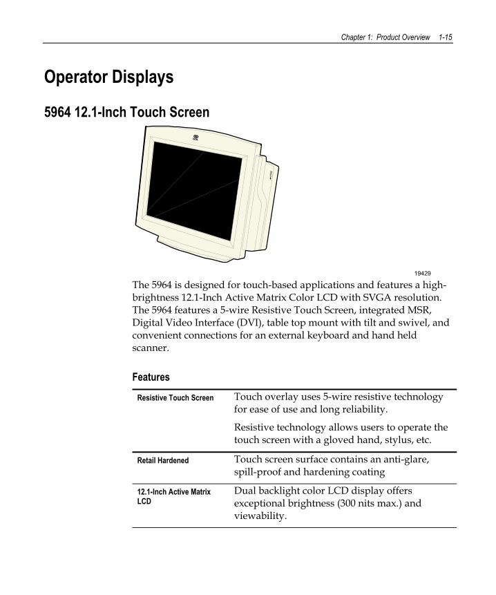
19429 The 5964 is designed for touch-based applications and features a high-brightness 12.1-Inch Active Matrix Color LCD with SVGA resolution. The 5964 features a 5-wire Resistive Touch Screen, integrated MSR, Digital Video Interface (DVI), table top mount with tilt and swivel, and convenient connections for an external keyboard and hand held scanner.
Features
Resistive Touch Screen Touch overlay uses 5-wire resistive technology for ease of use and long reliability.
Resistive technology allows users to operate the touch screen with a gloved hand, stylus, etc.
Retail Hardened Touch screen surface contains an anti-glare, spill-proof and hardening coating
12.1-Inch Active Matrix LCD
Dual backlight color LCD display offers exceptional brightness (300 nits max.) and viewability.
1-16 Chapter 1: Product Overview
Brightness Control The LCD is factory set to run at full brightness. Users can select reduced brightness through a user adjustable hardware switch below the right front bezel (high/low brightness).
Wide Viewing Angle Horizontal viewing angle of –60° to +60° (right to left), vertical –50° to +50° (bottom to top)
SVGA Resolution High resolution (800 x 600) supports the latest graphical and multimedia applications
PS/2 Keyboard Connector A convenient PS/2 connector supports a non-wedge PC-style keyboard for alpha entry and diagnostics
Scanner Connector RJ-45 interface provides 5 V power and communication for the NCR RS-232 hand-held scanner
Tone Speaker Sounds error tones & audible feedback during operator input - controlled by TAPS/OPOS commands
DVI Video Interface Industry standard DVI (Digital Video Interface) for connection to DVI-I connector on RealPOS 80c
RS-232 Touch Interface 7456 Powered RS-232 connector provides power and touch interface for NCR 5964 display
Wedge Controller Passes data (MSR, scanner, keyboard) to host terminal through PS/2 data stream via Y-cable
Terminal Powered No additional power cord or power supply is required simplifying cable management
MSR Option Integrated 3-track ISO MSR
Tilt / Swivel The remote table top pedestal mount supports tilt and swivel to adjust display to optimum angle
Chapter 1: Product Overview 1-17
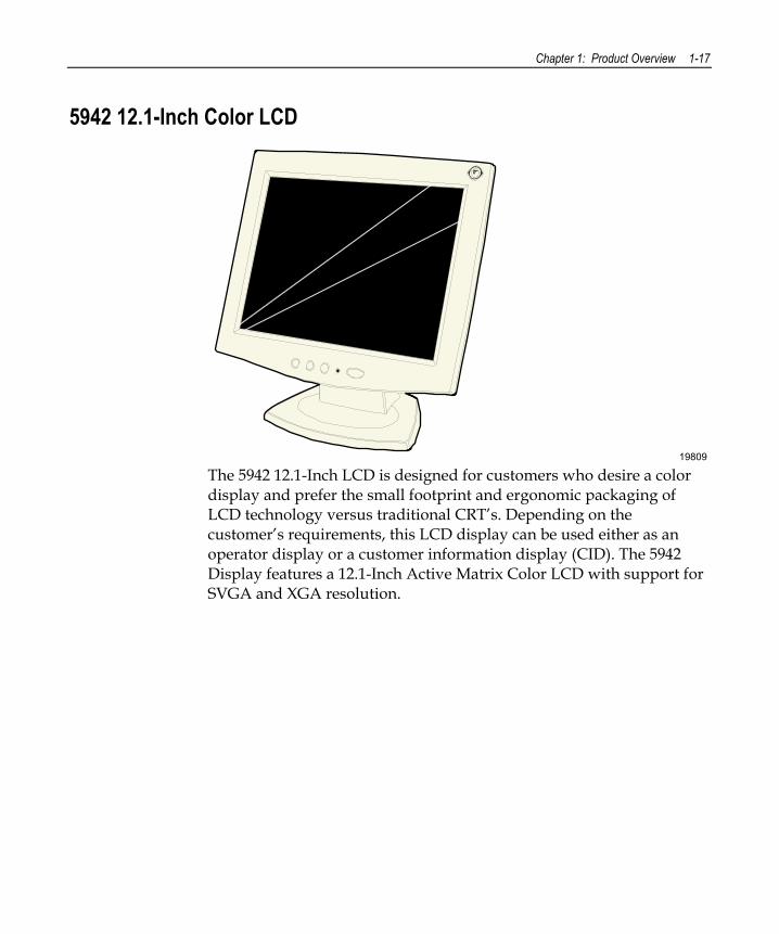
5942 12.1-Inch Color LCD
19809 The 5942 12.1-Inch LCD is designed for customers who desire a color display and prefer the small footprint and ergonomic packaging of LCD technology versus traditional CRT’s. Depending on the customer’s requirements, this LCD display can be used either as an operator display or a customer information display (CID). The 5942 Display features a 12.1-Inch Active Matrix Color LCD with support for SVGA and XGA resolution.
1-18 Chapter 1: Product Overview
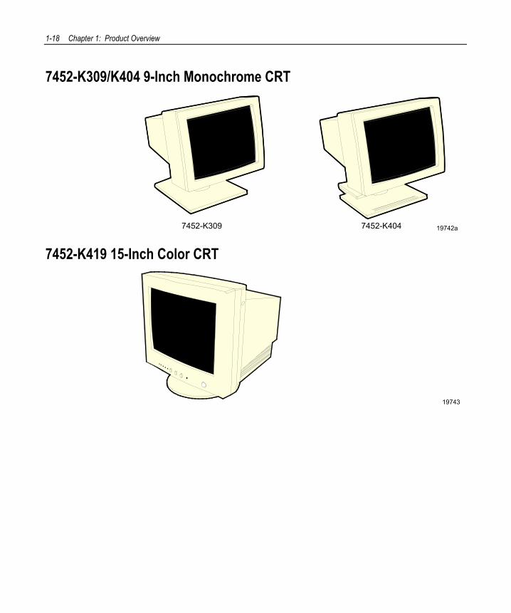
7452-K309/K404 9-Inch Monochrome CRT
19742a7452-K309 7452-K404
7452-K419 15-Inch Color CRT
19743
Chapter 1: Product Overview 1-19
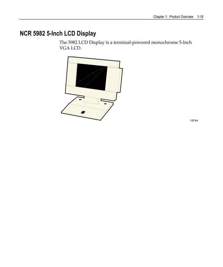
NCR 5982 5-Inch LCD Display The 5982 LCD Display is a terminal-powered monochrome 5-Inch VGA LCD.
19744
1-20 Chapter 1: Product Overview
NCR 5953 12.1-Inch DynaKey
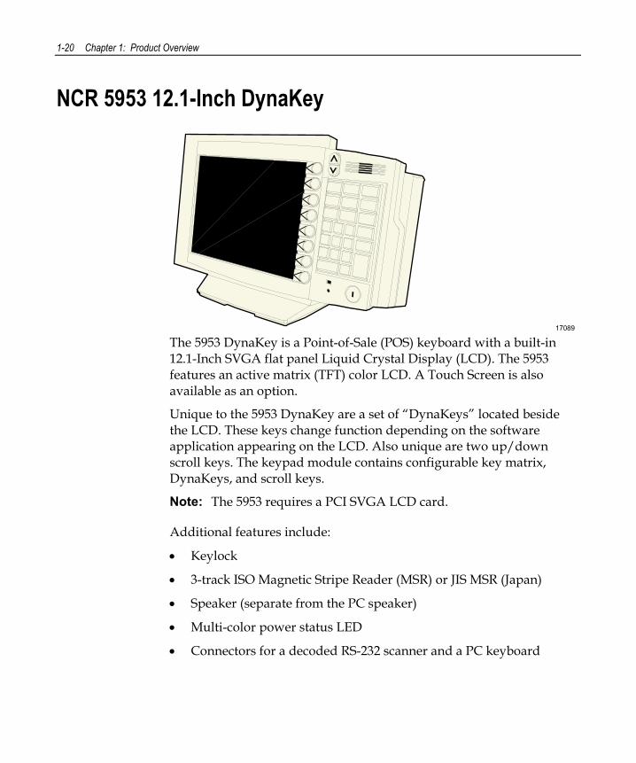
17089 The 5953 DynaKey is a Point-of-Sale (POS) keyboard with a built-in 12.1-Inch SVGA flat panel Liquid Crystal Display (LCD). The 5953 features an active matrix (TFT) color LCD. A Touch Screen is also available as an option.
Unique to the 5953 DynaKey are a set of “DynaKeys” located beside the LCD. These keys change function depending on the software application appearing on the LCD. Also unique are two up/down scroll keys. The keypad module contains configurable key matrix, DynaKeys, and scroll keys.
Note: The 5953 requires a PCI SVGA LCD card.
Additional features include:
• Keylock
• 3-track ISO Magnetic Stripe Reader (MSR) or JIS MSR (Japan)
• Speaker (separate from the PC speaker)
• Multi-color power status LED
• Connectors for a decoded RS-232 scanner and a PC keyboard
Chapter 1: Product Overview 1-21
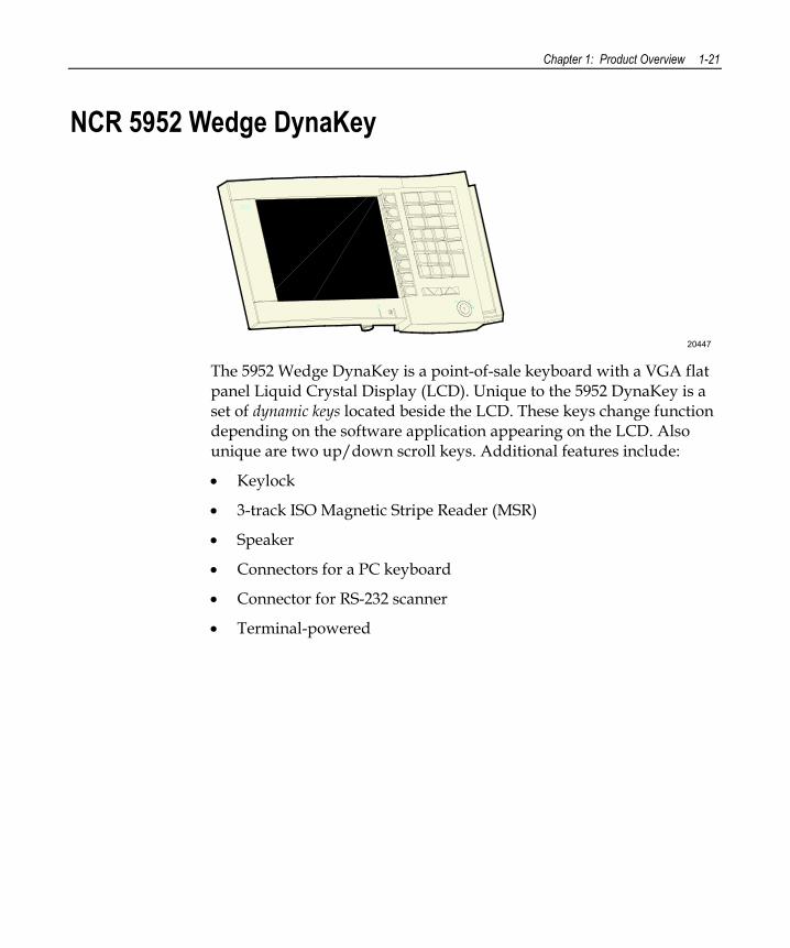
NCR 5952 Wedge DynaKey
20447 The 5952 Wedge DynaKey is a point-of-sale keyboard with a VGA flat panel Liquid Crystal Display (LCD). Unique to the 5952 DynaKey is a set of dynamic keys located beside the LCD. These keys change function depending on the software application appearing on the LCD. Also unique are two up/down scroll keys. Additional features include:
• Keylock
• 3-track ISO Magnetic Stripe Reader (MSR)
• Speaker
• Connectors for a PC keyboard
• Connector for RS-232 scanner
• Terminal-powered
1-22 Chapter 1: Product Overview
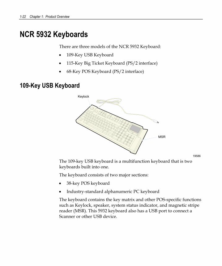
NCR 5932 Keyboards There are three models of the NCR 5932 Keyboard:
• 109-Key USB Keyboard
• 115-Key Big Ticket Keyboard (PS/2 interface)
• 68-Key POS Keyboard (PS/2 interface)
109-Key USB Keyboard
19586
MSR
Keylock
The 109-key USB keyboard is a multifunction keyboard that is two keyboards built into one.
The keyboard consists of two major sections:
• 38-key POS keyboard
• Industry-standard alphanumeric PC keyboard
The keyboard contains the key matrix and other POS-specific functions such as Keylock, speaker, system status indicator, and magnetic stripe reader (MSR). This 5932 keyboard also has a USB port to connect a Scanner or other USB device.
Chapter 1: Product Overview 1-23
Features The NCR 5932 USB Keyboard supports the following features:
• Keylock
• Speaker
• Magnetic Stripe Reader (MSR)
• Keyboard Status LEDs
Keylock The USB keyboard has a four-position Keylock. You can rotate the Keylock between specific positions by use of three keys. The positions are explained in the following table.
Abbreviation Position Description
Ex Exception Used by the customer or service representative to perform low level programming such as workstation diagnostics, configuring the workstation, or loading the workstation.
L Locked Used to lock keyboard input to prohibit use of normal functions.
R Register Used when performing normal retail mode functions.
S Supervisor Used by the supervisor to provide highest level of workstation control in cases such as refunds and running totals.
Speaker The programmable speaker is capable of generating key clicks and error tones.
1-24 Chapter 1: Product Overview
MSR The MSR is an optional feature that provides support for reading magnetically coded data cards. The keyboards support two different types of MSR:
• ISO Tracks 1, 2, and 3
• JIS-II and ISO Track 2
Keyboard Status LEDs The keyboard has three status LED’s:
• Num Lock
• Caps Lock
• Scroll Lock
These features are used to provide the present state of the keyboard. The indicators are single color (Green) LED’s. When the system is off, no LED’s are illuminated.
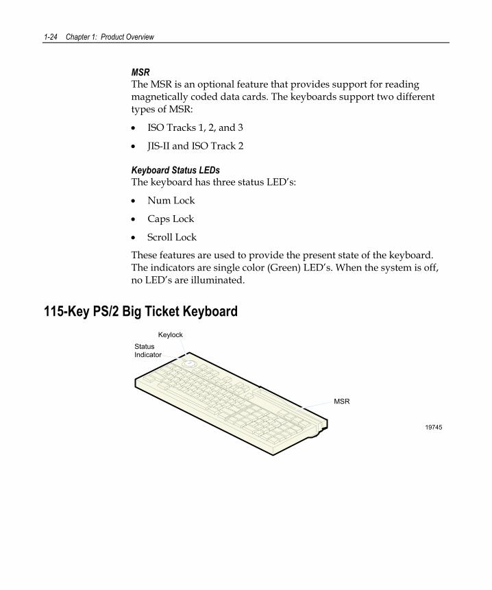
115-Key PS/2 Big Ticket Keyboard
19745
MSR
StatusIndicator
Keylock
Chapter 1: Product Overview 1-25
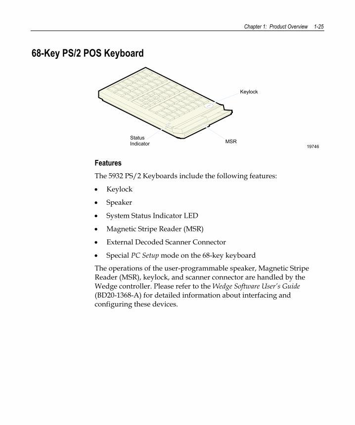
68-Key PS/2 POS Keyboard
19746MSR
StatusIndicator
Keylock
Features The 5932 PS/2 Keyboards include the following features:
• Keylock
• Speaker
• System Status Indicator LED
• Magnetic Stripe Reader (MSR)
• External Decoded Scanner Connector
• Special PC Setup mode on the 68-key keyboard
The operations of the user-programmable speaker, Magnetic Stripe Reader (MSR), keylock, and scanner connector are handled by the Wedge controller. Please refer to the Wedge Software User’s Guide (BD20-1368-A) for detailed information about interfacing and configuring these devices.
1-26 Chapter 1: Product Overview
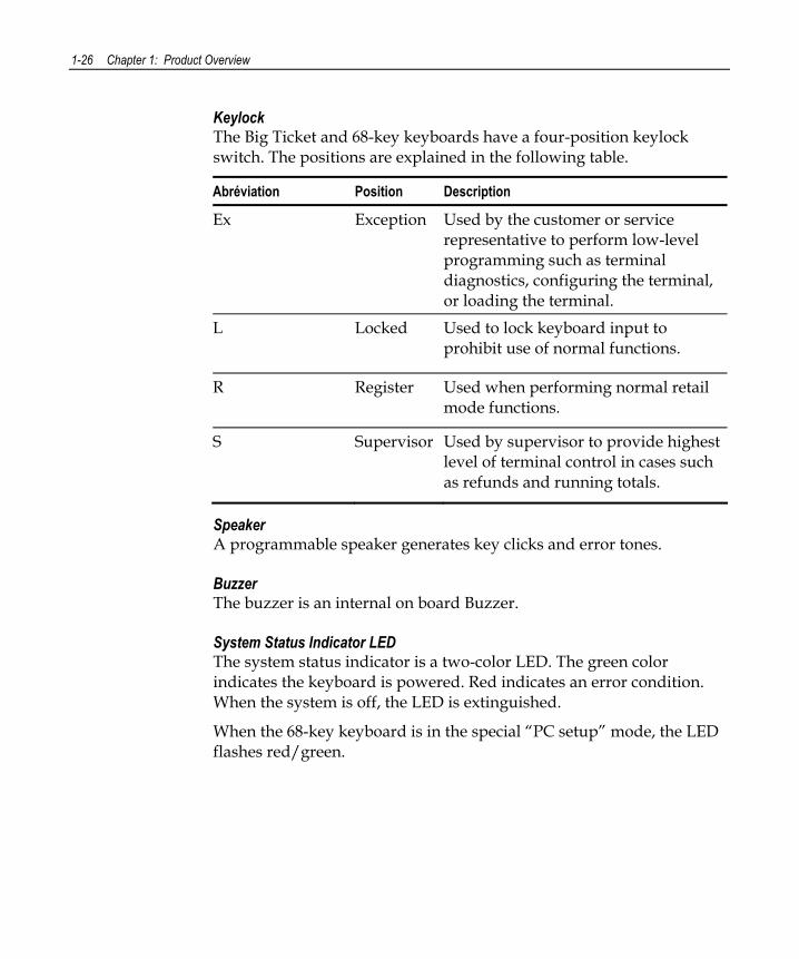
Keylock The Big Ticket and 68-key keyboards have a four-position keylock switch. The positions are explained in the following table.
Abréviation Position Description
Ex Exception Used by the customer or service representative to perform low-level programming such as terminal diagnostics, configuring the terminal, or loading the terminal.
L Locked Used to lock keyboard input to prohibit use of normal functions.
R Register Used when performing normal retail mode functions.
S Supervisor Used by supervisor to provide highest level of terminal control in cases such as refunds and running totals.
Speaker A programmable speaker generates key clicks and error tones.
Buzzer The buzzer is an internal on board Buzzer.
System Status Indicator LED The system status indicator is a two-color LED. The green color indicates the keyboard is powered. Red indicates an error condition. When the system is off, the LED is extinguished.
When the 68-key keyboard is in the special “PC setup” mode, the LED flashes red/green.
Chapter 1: Product Overview 1-27
The status and condition indicated by the LED are shown as follows:
Status Condition
Green Power on Red Wedge controller reporting an error condition Flashing red/green Keypad of 68-key keyboard in “PC Setup” mode
(See special keypad mode on next page) Off System off
Note: For more information about the Wedge controller, refer to Wedge Software User’s Guide (BST0-1368-B).
MSR (Magnetic Stripe Reader) The MSR is an optional feature that provides support for reading magnetically coded data cards. The keyboards support two different types of MSR:
• ISO Tracks 1, 2, and 3
• JIS-II and ISO Track 2 (Big Ticket and full-featured 68-key keyboards only)
Note: MSR signals are routed to the Wedge controller and passed into the system keyboard data stream. For more information about the Wedge controller, refer to Wedge Software User’s Guide (BD20-1368-A)
External Decoded Scanner Connector A decoded RS-232 input device that only requires TXD, RXD, CTS and RTS, such as a bar-code scanner, can be connected to the keyboard. RS-232 signals are routed to the Wedge controller and passed into the system keyboard data stream. The connector provides +5V to power the scanner. For more information about the Wedge controller, refer to Wedge Software User’s Guide (BD20-1368-A).
1-28 Chapter 1: Product Overview
Special “PC Setup” Keypad Layout for 68-key Keyboard On power-up, the operator can switch the 68-key keyboard into an alternate keypad layout that can be used with many PC BIOS setup and configuration routines. The alternate layout contains keys such as ESC, TAB, END, “+”, “-“ and arrow keys which are not available in the normal keypad layout. The alternate layout allows the operator to configure a PC with the 68-key keyboard.
Chapter 1: Product Overview 1-29
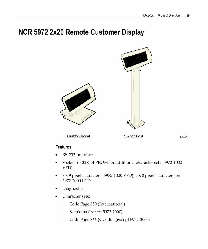
NCR 5972 2x20 Remote Customer Display
2044816-Inch PostDesktop Model
Features • RS-232 Interface
• Socket for 32K of PROM for additional character sets (5972-1000 VFD).
• 7 x 9 pixel characters (5972-1000 VFD); 5 x 8 pixel characters on 5972-2000 LCD
• Diagnostics
• Character sets:
− Code Page 850 (International)
− Katakana (except 5972-2000)
− Code Page 866 (Cyrillic) (except 5972-2000)
1-30 Chapter 1: Product Overview
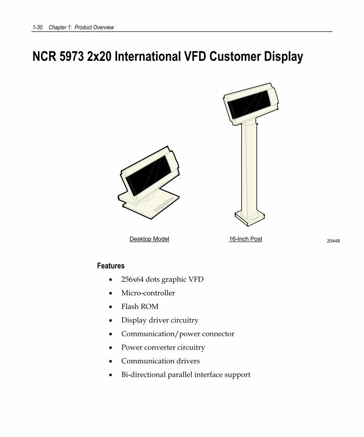
NCR 5973 2x20 International VFD Customer Display
2044816-Inch PostDesktop Model
Features • 256x64 dots graphic VFD
• Micro-controller
• Flash ROM
• Display driver circuitry
• Communication/power connector
• Power converter circuitry
• Communication drivers
• Bi-directional parallel interface support
Chapter 1: Product Overview 1-31
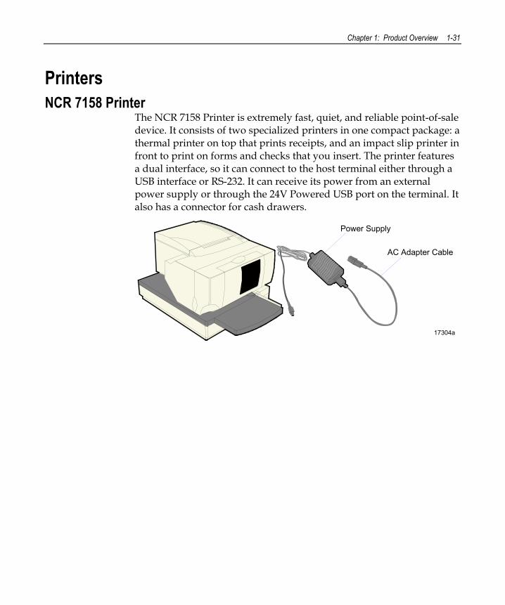
Printers NCR 7158 Printer
The NCR 7158 Printer is extremely fast, quiet, and reliable point-of-sale device. It consists of two specialized printers in one compact package: a thermal printer on top that prints receipts, and an impact slip printer in front to print on forms and checks that you insert. The printer features a dual interface, so it can connect to the host terminal either through a USB interface or RS-232. It can receive its power from an external power supply or through the 24V Powered USB port on the terminal. It also has a connector for cash drawers.
17304a
Power Supply
AC Adapter Cable
1-32 Chapter 1: Product Overview
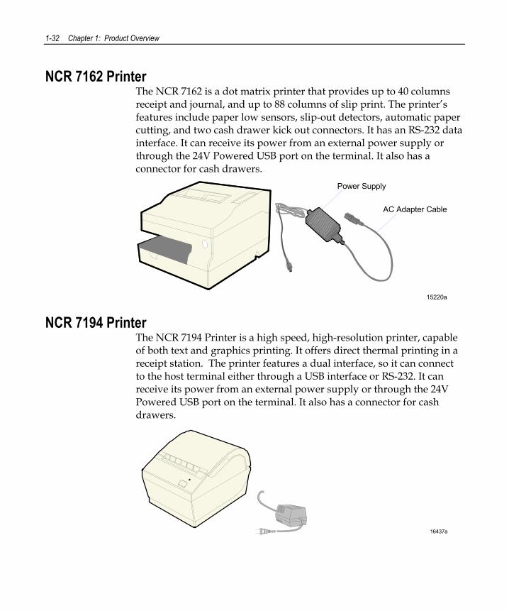
NCR 7162 Printer The NCR 7162 is a dot matrix printer that provides up to 40 columns receipt and journal, and up to 88 columns of slip print. The printer’s features include paper low sensors, slip-out detectors, automatic paper cutting, and two cash drawer kick out connectors. It has an RS-232 data interface. It can receive its power from an external power supply or through the 24V Powered USB port on the terminal. It also has a connector for cash drawers.
15220a
Power Supply
AC Adapter Cable
NCR 7194 Printer The NCR 7194 Printer is a high speed, high-resolution printer, capable of both text and graphics printing. It offers direct thermal printing in a receipt station. The printer features a dual interface, so it can connect to the host terminal either through a USB interface or RS-232. It can receive its power from an external power supply or through the 24V Powered USB port on the terminal. It also has a connector for cash drawers.
16437a
Chapter 1: Product Overview 1-33
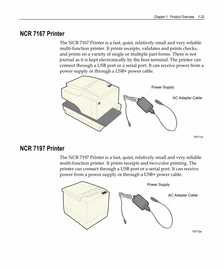
NCR 7167 Printer The NCR 7167 Printer is a fast, quiet, relatively small and very reliable multi-function printer. It prints receipts, validates and prints checks, and prints on a variety of single or multiple part forms. There is not journal as it is kept electronically by the host terminal. The printer can connect through a USB port or a serial port. It can receive power from a power supply or through a USB+ power cable.
19711a
Power Supply
AC Adapter Cable
NCR 7197 Printer The NCR 7197 Printer is a fast, quiet, relatively small and very reliable multi-function printer. It prints receipts and two-color printing. The printer can connect through a USB port or a serial port. It can receive power from a power supply or through a USB+ power cable.
19712a
Power Supply
AC Adapter Cable
1-34 Chapter 1: Product Overview
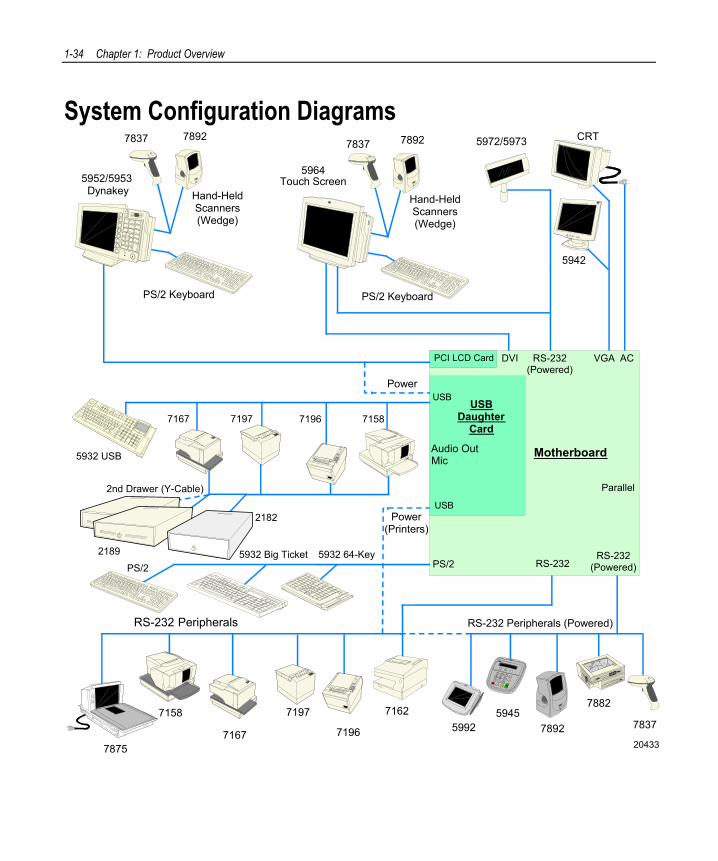
System Configuration Diagrams
5932 64-Key5932 Big Ticket
2182
2nd Drawer (Y-Cable)
2189
PS/2
20433
RS-232 Peripherals
5972/5973
LAN
5952/5953 Dynakey
PS/2 Keyboard
Hand-HeldScanners(Wedge)
7837 7892
5964Touch Screen
PS/2 Keyboard
Hand-HeldScanners(Wedge)
7837 7892 CRT
78757196
7162
Motherboard
PCI LCD Card
Parallel
DVI VGA AC
7197
7167
7158
5932 USB
71587196USB
DaughterCard
USB
Audio OutMic
USB
71977167
RS-232(Powered)
5942
PS/2 RS-232RS-232
(Powered)
59925945
7892 7837
RS-232 Peripherals (Powered)
7882
Power
Power(Printers)
Chapter 2: Hardware Installation
Introduction This chapter explains how to install the RealPOS 80c hardware, including out-of-box installation and how to install the optional peripheral devices.
Installation Restrictions • Before installing the RealPOS 80c, read and follow the guidelines in
the RealPOS 80c Site Preparation (B005-0000-1360) and the NCR Workstation and Peripheral AC Wiring Guide (BST0-2115-53).
• Install the RealPOS 80c near an electrical outlet that is easily accessible. Use the power cord as a power disconnect device.
• Do not permit any object to rest on the power cord. Do not locate the RealPOS 80c where the power cord can be walked on.
• Use a grounding strap or touch a grounded metal object to discharge any static electricity from your body before servicing the RealPOS 80c.
Caution: This unit contains hazardous voltages and should only be serviced by qualified service personnel.
Caution: Do not connect or disconnect the transaction printer while the terminal is on. This can result in system or printer damage.
2-2 Chapter 2: Hardware Installation
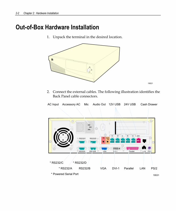
Out-of-Box Hardware Installation 1. Unpack the terminal in the desired location.
19521 2. Connect the external cables. The following illustration identifies the
Back Panel cable connectors.
Mic Audio Out
E D C B A 24VRS232/C RS232/D
RS232/A RS232/B VGA DVI-1 Parallel LAN PS/2
19531
* RS232/A RS232/B
* RS232/C * RS232/D
VGA DVI-1 Parallel LAN PS/2
12V USB 24V USB Cash DrawerAC Input Accessory AC Mic Audio Out
* Powered Serial Port
Chapter 2: Hardware Installation 2-3
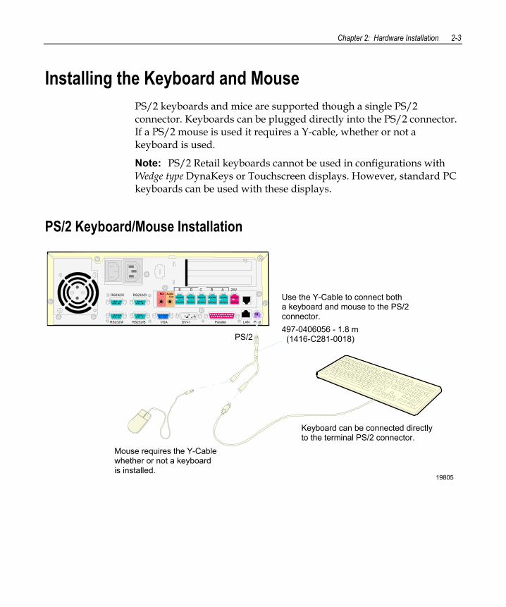
Installing the Keyboard and Mouse PS/2 keyboards and mice are supported though a single PS/2 connector. Keyboards can be plugged directly into the PS/2 connector. If a PS/2 mouse is used it requires a Y-cable, whether or not a keyboard is used.
Note: PS/2 Retail keyboards cannot be used in configurations with Wedge type DynaKeys or Touchscreen displays. However, standard PC keyboards can be used with these displays.
PS/2 Keyboard/Mouse Installation
19805
Mic Audio Out
E D C B A 24VRS232/C RS232/D
RS232/A RS232/B VGA DVI-1 Parallel LAN PS/2
PS/2
Keyboard can be connected directlyto the terminal PS/2 connector.
Mouse requires the Y-Cable whether or not a keyboardis installed.
Use the Y-Cable to connect botha keyboard and mouse to the PS/2connector.497-0406056 - 1.8 m(1416-C281-0018)
2-4 Chapter 2: Hardware Installation
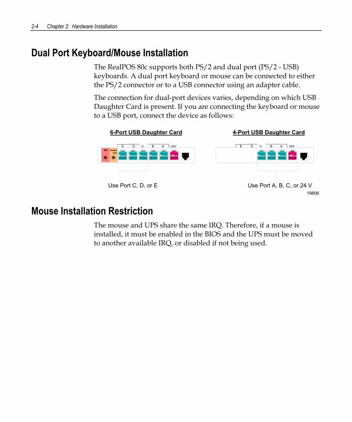
Dual Port Keyboard/Mouse Installation The RealPOS 80c supports both PS/2 and dual port (PS/2 - USB) keyboards. A dual port keyboard or mouse can be connected to either the PS/2 connector or to a USB connector using an adapter cable.
The connection for dual-port devices varies, depending on which USB Daughter Card is present. If you are connecting the keyboard or mouse to a USB port, connect the device as follows:
19806
Mic Audio Out
E D C B A 24V
Use Port C, D, or E
E D C B A 24V
6-Port USB Daughter Card 4-Port USB Daughter Card
Use Port A, B, C, or 24 V
Mouse Installation Restriction The mouse and UPS share the same IRQ. Therefore, if a mouse is installed, it must be enabled in the BIOS and the UPS must be moved to another available IRQ, or disabled if not being used.
Chapter 2: Hardware Installation 2-5
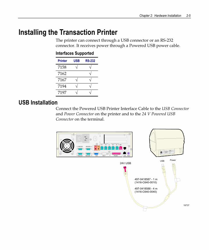
Installing the Transaction Printer The printer can connect through a USB connector or an RS-232 connector. It receives power through a Powered USB power cable.
Interfaces Supported Printer USB RS-232
7158 √ √ 7162 √ 7167 √ √ 7194 √ √ 7197 √ √
USB Installation Connect the Powered USB Printer Interface Cable to the USB Connector and Power Connector on the printer and to the 24 V Powered USB Connector on the terminal.
19737
PowerUSB
Mic Audio Out
E D C B A 24VRS232/C RS232/D
RS232/A RS232/B VGA DVI-1 Parallel LAN PS/2
24V USB
497-0418587 - 1 m(1416-C640-0010)
497-0418588 - 4 m(1416-C640-0040)
2-6 Chapter 2: Hardware Installation
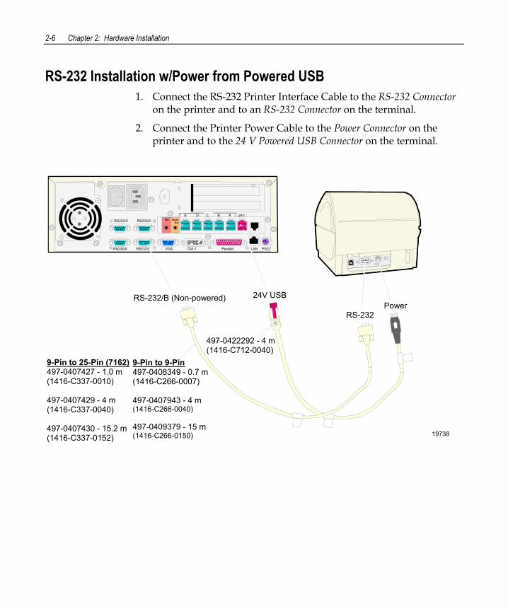
RS-232 Installation w/Power from Powered USB 1. Connect the RS-232 Printer Interface Cable to the RS-232 Connector
on the printer and to an RS-232 Connector on the terminal.
2. Connect the Printer Power Cable to the Power Connector on the printer and to the 24 V Powered USB Connector on the terminal.
19738
Mic Audio Out
E D C B A 24VRS232/C RS232/D
RS232/A RS232/B VGA DVI-1 Parallel LAN PS/2
PowerRS-232
24V USBRS-232/B (Non-powered)
9-Pin to 9-Pin497-0408349 - 0.7 m(1416-C266-0007)
497-0407943 - 4 m(1416-C266-0040)
497-0409379 - 15 m(1416-C266-0150)
9-Pin to 25-Pin (7162)497-0407427 - 1.0 m(1416-C337-0010)
497-0407429 - 4 m(1416-C337-0040)
497-0407430 - 15.2 m(1416-C337-0152)
497-0422292 - 4 m(1416-C712-0040)
Chapter 2: Hardware Installation 2-7
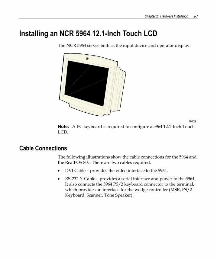
Installing an NCR 5964 12.1-Inch Touch LCD The NCR 5964 serves both as the input device and operator display.
19429 Note: A PC keyboard is required to configure a 5964 12.1-Inch Touch LCD.
Cable Connections The following illustrations show the cable connections for the 5964 and the RealPOS 80c. There are two cables required.
• DVI Cable – provides the video interface to the 5964.
• RS-232 Y-Cable – provides a serial interface and power to the 5964. It also connects the 5964 PS/2 keyboard connector to the terminal, which provides an interface for the wedge controller (MSR, PS/2 Keyboard, Scanner, Tone Speaker).
2-8 Chapter 2: Hardware Installation
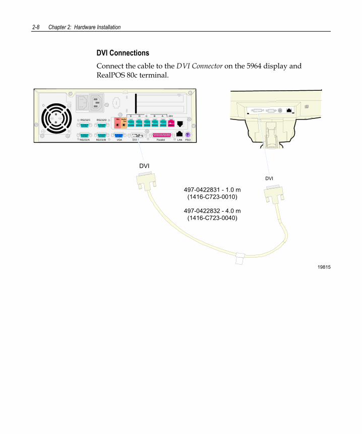
DVI Connections Connect the cable to the DVI Connector on the 5964 display and RealPOS 80c terminal.
19815
DVI
Mic Audio Out
E D C B A 24VRS232/C RS232/D
RS232/A RS232/B VGA DVI-1 Parallel LAN PS/2
DVI
497-0422831 - 1.0 m(1416-C723-0010)
497-0422832 - 4.0 m(1416-C723-0040)
Chapter 2: Hardware Installation 2-9
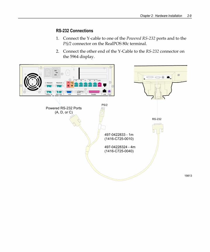
RS-232 Connections 1. Connect the Y-cable to one of the Powered RS-232 ports and to the
PS/2 connector on the RealPOS 80c terminal.
2. Connect the other end of the Y-Cable to the RS-232 connector on the 5964 display.
19813
PS/2
RS-232
Mic Audio Out
E D C B A 24VRS232/C RS232/D
RS232/A RS232/B VGA DVI-1 Parallel LAN PS/2
Powered RS-232 Ports(A, D, or C)
497-0422833 - 1m(1416-C725-0010)
497-04228324 - 4m(1416-C725-0040)
2-10 Chapter 2: Hardware Installation
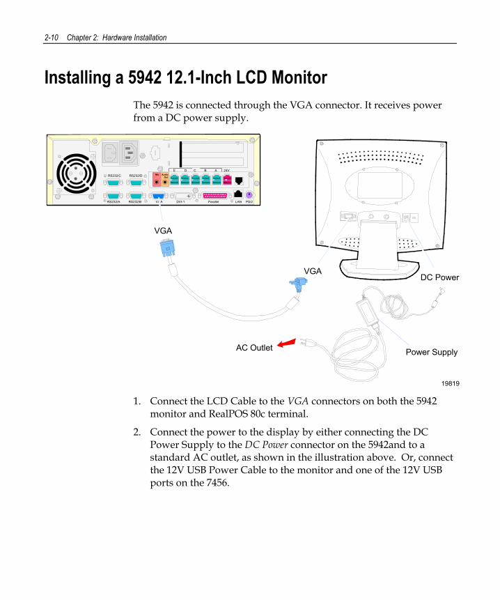
Installing a 5942 12.1-Inch LCD Monitor The 5942 is connected through the VGA connector. It receives power from a DC power supply.
19819
Mic Audio Out
E D C B A 24VRS232/C RS232/D
RS232/A RS232/B VGA DVI-1 Parallel LAN PS/2
Power Supply
VGADC Power
AC Outlet
VGA
1. Connect the LCD Cable to the VGA connectors on both the 5942
monitor and RealPOS 80c terminal.
2. Connect the power to the display by either connecting the DC Power Supply to the DC Power connector on the 5942and to a standard AC outlet, as shown in the illustration above. Or, connect the 12V USB Power Cable to the monitor and one of the 12V USB ports on the 7456.

Chapter 2: Hardware Installation 2-11
Installing a 5953 DynaKey
17089 The 5953 DynaKey is a combined display and keyboard device. It can be installed in the following configurations:
• Integrated in the 7456
• 5953-F022 Remote Table Top Mount
• 7401-K533 Wall Mount
• 5952-K024 Checkstand Mount w/Base
• 5953-K023 Checkstand Mount
There are two types of interface models of the 5953 DynaKey. For installation information for each, refer to their respective User Guides. • NCR RealPOS 5953 USB DynaKey User's Guide (B005-0000-1457)
• NCR RealPOS 5953 PS/2 DynaKey User's Guide (B005-0000-1161)
2-12 Chapter 2: Hardware Installation
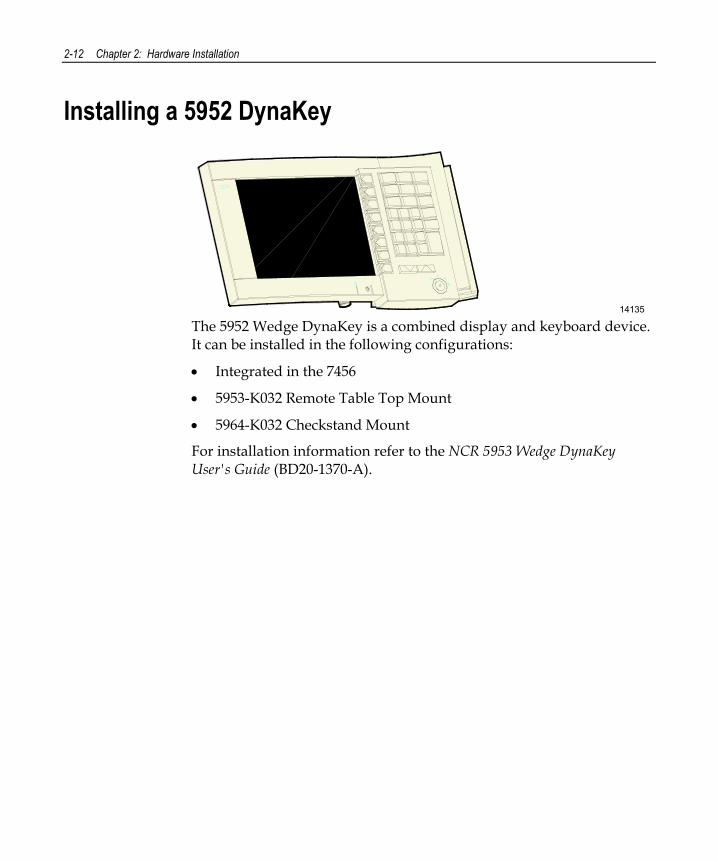
Installing a 5952 DynaKey
14135 The 5952 Wedge DynaKey is a combined display and keyboard device. It can be installed in the following configurations:
• Integrated in the 7456
• 5953-K032 Remote Table Top Mount
• 5964-K032 Checkstand Mount
For installation information refer to the NCR 5953 Wedge DynaKey User's Guide (BD20-1370-A).
Chapter 2: Hardware Installation 2-13
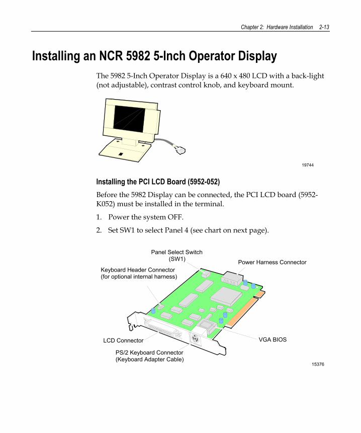
Installing an NCR 5982 5-Inch Operator Display The 5982 5-Inch Operator Display is a 640 x 480 LCD with a back-light (not adjustable), contrast control knob, and keyboard mount.
19744
Installing the PCI LCD Board (5952-052) Before the 5982 Display can be connected, the PCI LCD board (5952-K052) must be installed in the terminal.
1. Power the system OFF.
2. Set SW1 to select Panel 4 (see chart on next page).
15376
Keyboard Header Connector(for optional internal harness)
Panel Select Switch (SW1) Power Harness Connector
VGA BIOS
PS/2 Keyboard Connector(Keyboard Adapter Cable)
LCD Connector
2-14 Chapter 2: Hardware Installation
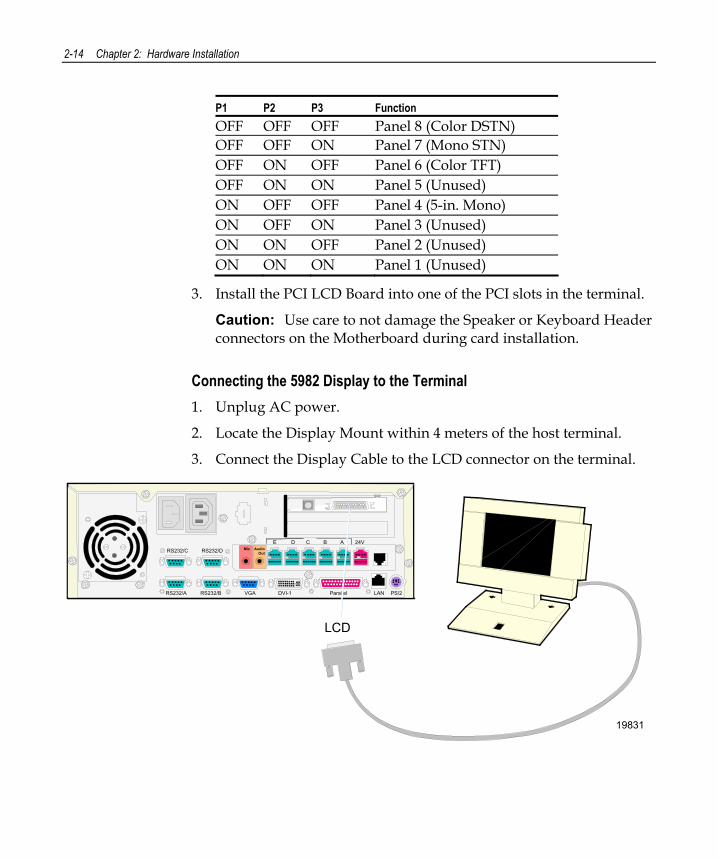
P1 P2 P3 Function OFF OFF OFF Panel 8 (Color DSTN) OFF OFF ON Panel 7 (Mono STN) OFF ON OFF Panel 6 (Color TFT) OFF ON ON Panel 5 (Unused) ON OFF OFF Panel 4 (5-in. Mono) ON OFF ON Panel 3 (Unused) ON ON OFF Panel 2 (Unused) ON ON ON Panel 1 (Unused)
3. Install the PCI LCD Board into one of the PCI slots in the terminal.
Caution: Use care to not damage the Speaker or Keyboard Header connectors on the Motherboard during card installation.
Connecting the 5982 Display to the Terminal 1. Unplug AC power.
2. Locate the Display Mount within 4 meters of the host terminal.
3. Connect the Display Cable to the LCD connector on the terminal.
19831
Mic Audio Out
E D C B A 24VRS232/C RS232/D
RS232/A RS232/B VGA DVI-1 Parallel LAN PS/2
LCD
Chapter 2: Hardware Installation 2-15
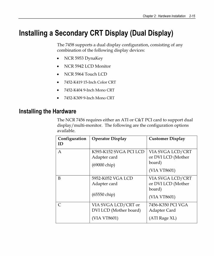
Installing a Secondary CRT Display (Dual Display) The 7458 supports a dual display configuration, consisting of any combination of the following display devices:
• NCR 5953 DynaKey
• NCR 5942 LCD Monitor
• NCR 5964 Touch LCD
• 7452-K419 15-Inch Color CRT
• 7452-K404 9-Inch Mono CRT
• 7452-K309 9-Inch Mono CRT
Installing the Hardware The NCR 7456 requires either an ATI or C&T PCI card to support dual display/multi-monitor. The following are the configuration options available.
Configuration ID
Operator Display Customer Display
A K593-K152 SVGA PCI LCD Adapter card
(69000 chip)
VIA SVGA LCD/CRT or DVI LCD (Mother board)
(VIA VT8601)
B 5952-K052 VGA LCD Adapter card (65550 chip)
VIA SVGA LCD/CRT or DVI LCD (Mother board)
(VIA VT8601)
C VIA SVGA LCD/CRT or DVI LCD (Mother board)
(VIA VT8601)
7456-K350 PCI VGA Adapter Card
(ATI Rage XL)
2-16 Chapter 2: Hardware Installation
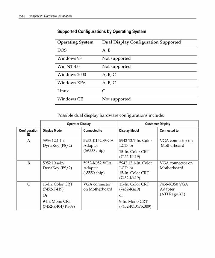
Supported Configurations by Operating System
Operating System Dual Display Configuration Supported
DOS A, B
Windows 98 Not supported
Win NT 4.0 Not supported
Windows 2000 A, B, C
Windows XPe A, B, C
Linux C
Windows CE Not supported
Possible dual display hardware configurations include:
Operator Display Customer Display
Configuration ID
Display Model Connected to Display Model Connected to
A 5953 12.1-In. DynaKey (PS/2)
5953-K152 SVGA Adapter (69000 chip)
5942 12.1-In. Color LCD or 15-In. Color CRT (7452-K419)
VGA connector on Motherboard
B 5952 10.4-In. DynaKey (PS/2)
5952-K052 VGA Adapter (65550 chip)
5942 12.1-In. Color LCD or 15-In. Color CRT (7452-K419)
VGA connector on Motherboard
C 15-In. Color CRT (7452-K419) Or 9-In. Mono CRT (7452-K404/K309)
VGA connector on Motherboard
15-In. Color CRT (7452-K419) or 9-In. Mono CRT (7452-K404/K309)
7456-K350 VGA Adapter (ATI Rage XL)
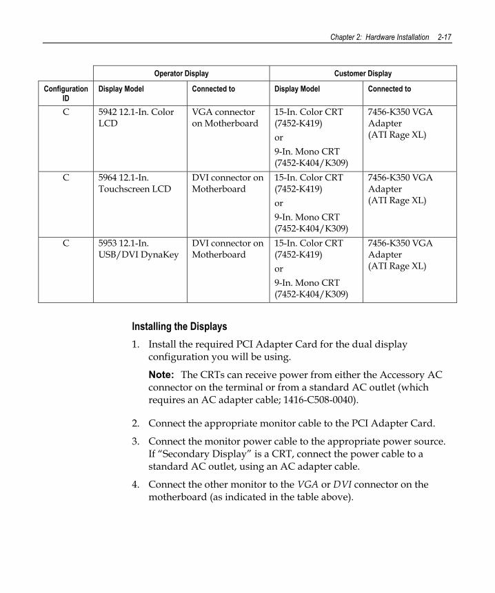
Chapter 2: Hardware Installation 2-17
Operator Display Customer Display
Configuration ID
Display Model Connected to Display Model Connected to
C 5942 12.1-In. Color LCD
VGA connector on Motherboard
15-In. Color CRT (7452-K419) or 9-In. Mono CRT (7452-K404/K309)
7456-K350 VGA Adapter (ATI Rage XL)
C 5964 12.1-In. Touchscreen LCD
DVI connector on Motherboard
15-In. Color CRT (7452-K419) or 9-In. Mono CRT (7452-K404/K309)
7456-K350 VGA Adapter (ATI Rage XL)
C 5953 12.1-In. USB/DVI DynaKey
DVI connector on Motherboard
15-In. Color CRT (7452-K419) or 9-In. Mono CRT (7452-K404/K309)
7456-K350 VGA Adapter (ATI Rage XL)
Installing the Displays 1. Install the required PCI Adapter Card for the dual display
configuration you will be using.
Note: The CRTs can receive power from either the Accessory AC connector on the terminal or from a standard AC outlet (which requires an AC adapter cable; 1416-C508-0040).
2. Connect the appropriate monitor cable to the PCI Adapter Card.
3. Connect the monitor power cable to the appropriate power source. If “Secondary Display” is a CRT, connect the power cable to a standard AC outlet, using an AC adapter cable.
4. Connect the other monitor to the VGA or DVI connector on the motherboard (as indicated in the table above).
2-18 Chapter 2: Hardware Installation
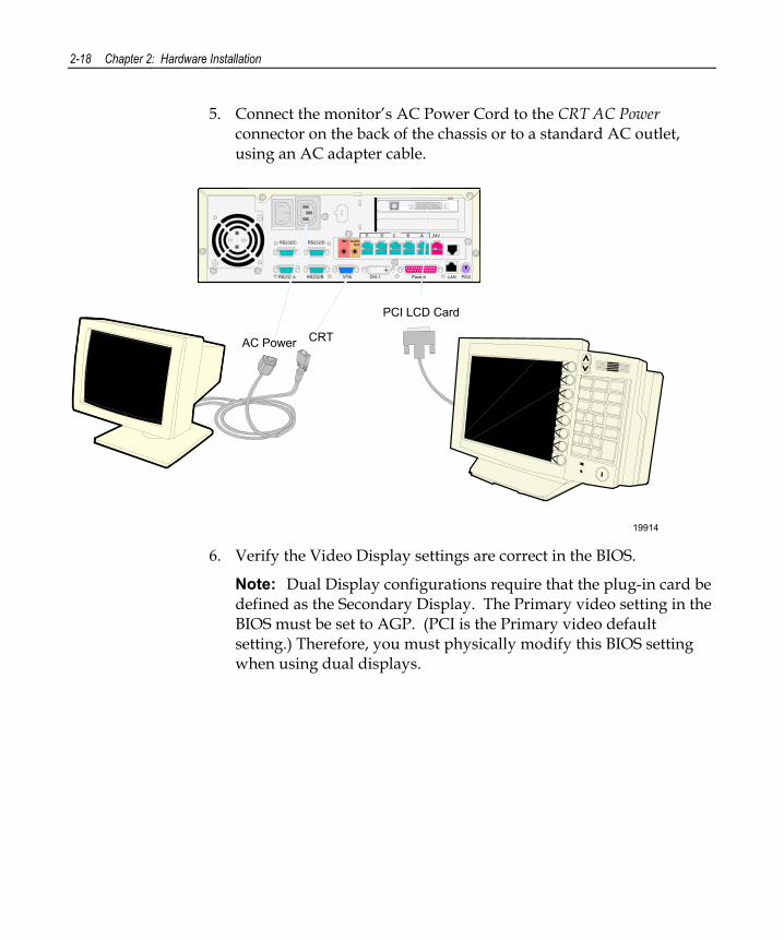
5. Connect the monitor’s AC Power Cord to the CRT AC Power connector on the back of the chassis or to a standard AC outlet, using an AC adapter cable.
19914
Mic Audio Out
E D C B A 24VRS232/C RS232/D
RS232/A RS232/B VGA DVI-1 Parallel LAN PS/2
PCI LCD Card
CRTAC Power
6. Verify the Video Display settings are correct in the BIOS.
Note: Dual Display configurations require that the plug-in card be defined as the Secondary Display. The Primary video setting in the BIOS must be set to AGP. (PCI is the Primary video default setting.) Therefore, you must physically modify this BIOS setting when using dual displays.
Chapter 2: Hardware Installation 2-19
Configuring the Software for Dual Display Verify that the appropriate drivers are installed and that the Operating System is configured to run dual displays (multi-monitor).
For dual display on DOS systems, custom Dual Display Drivers are required to permit the application to switch output from one display to the other. These drivers are found on the Customer Information Display (CID) Driver for DOS, WIN 3.1, Win95 LPIN (G370-0828-0000).
For additional software installation information, see the Customer Information Display (Dual Display) User’s Guide, (BD20-1431-B).
2-20 Chapter 2: Hardware Installation
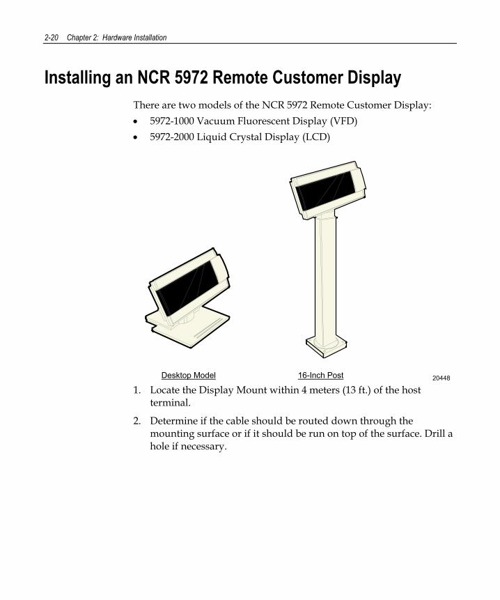
Installing an NCR 5972 Remote Customer Display There are two models of the NCR 5972 Remote Customer Display: • 5972-1000 Vacuum Fluorescent Display (VFD) • 5972-2000 Liquid Crystal Display (LCD)
2044816-Inch PostDesktop Model 1. Locate the Display Mount within 4 meters (13 ft.) of the host
terminal.
2. Determine if the cable should be routed down through the mounting surface or if it should be run on top of the surface. Drill a hole if necessary.
Chapter 2: Hardware Installation 2-21
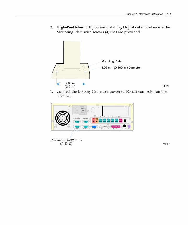
3. High-Post Mount: If you are installing High-Post model secure the Mounting Plate with screws (4) that are provided.
14622
Mounting Plate
4.06 mm (0.160 in.) Diameter
7.6 cm (3.0 in.)
1. Connect the Display Cable to a powered RS-232 connector on the terminal.
19807
Mic Audio Out
E D C B A 24VRS232/C RS232/D
RS232/A RS232/B VGA DVI-1 Parallel LAN PS/2
Powered RS-232 Ports(A, D, C)
2-22 Chapter 2: Hardware Installation
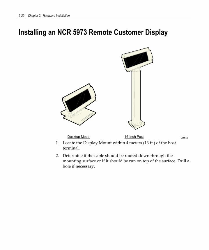
Installing an NCR 5973 Remote Customer Display
2044816-Inch PostDesktop Model 1. Locate the Display Mount within 4 meters (13 ft.) of the host
terminal.
2. Determine if the cable should be routed down through the mounting surface or if it should be run on top of the surface. Drill a hole if necessary.
Chapter 2: Hardware Installation 2-23
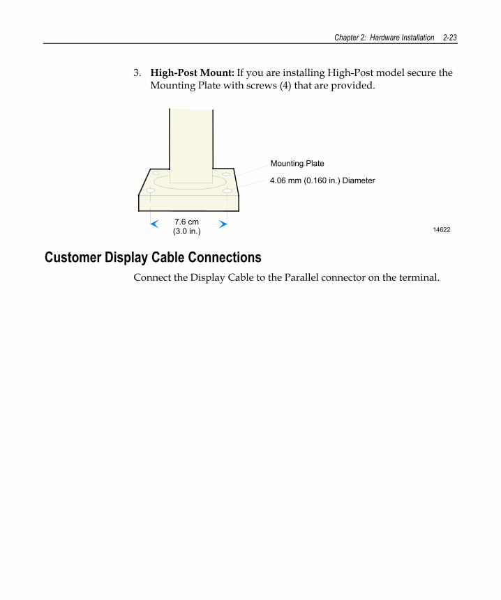
3. High-Post Mount: If you are installing High-Post model secure the Mounting Plate with screws (4) that are provided.
14622
Mounting Plate
4.06 mm (0.160 in.) Diameter
7.6 cm (3.0 in.)
Customer Display Cable Connections Connect the Display Cable to the Parallel connector on the terminal.

2-24 Chapter 2: Hardware Installation
Chapter 3: Setup
Introduction This chapter describes how to configure the BIOS options.
An external alphanumeric keyboard is not required to run the BIOS CMOS Setup Utility, but a keyboard makes the setup easier.
The Setup Menus in this chapter reference NCR RealPOS 80c/7458 BIOS, Version 3.0.2.2.
Entering Setup Using a Keyboard 1. Apply power to the terminal.
2. Press the F2 key when you see the NCR logo displayed.
Note: Setup can also be entered from the Boot Menu that is displayed when you press ESC during POST.
How to Select Menu Options The following keyboard controls are used to select the various menu options and to make changes to their values.
• Use the arrow keys to select (highlight) options and menu screens.
• Use the + and - (or F5 and F6) keys to change field values.
• To view help information on the possible selections for the highlighted item, press F1.
• To save the changes, move the cursor to the Exit Menu, select either Save Changes & Exit or Save Changes, and press [Enter].
3-2 Chapter 3: Setup
Restoring Factory Settings To reset all values to their default settings for the current screen, press F9. The terminal automatically loads the BIOS default values.
To reset all BIOS settings to their default settings go to the Exit menu, press F9, select either Save Changes & Exit or Save Changes, and press [Enter].
See the BIOS Default Settings section later in this chapter for the pre-installed Setup defaults.
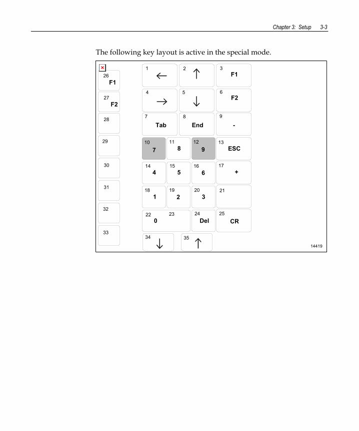
Special DynaKey Keypad Mode If your Terminal is configured with a DynaKey or Touch Screen module refer to the following sections that discuss special keypad considerations. Otherwise, proceed to the Configuration Setup Procedures section.
Many of the Terminal setup routines require keys that are not present in the regular DynaKey keypad layout (such as the ESC and .0END keys). Although the DynaKey has a PC keyboard connector, a PC keyboard may not be readily available to the operator.
Note: No setup is required for the DynaKey module itself at installation unless the factory default configuration needs changing. The operational parameters can be changed using the Wedge Configuration Utility (G370-0701-0000) diskette or the 7452 Diagnostics and BIOS Images (497-0406703) diskette.
To use the DynaKey without a PC keyboard attached to run the Terminal setup routines, you must place it in the Special DynaKey Keypad Mode. This mode replaces the normal keypad layout and function keys with special key assignments that are required to run setup. To enter the special mode, press the 7 and 9 keys simultaneously during POST diagnostics.
Note: The 7 and 9 keys must be the FIRST keys pressed during/after a power up, otherwise the keypad enters the normal layout.
Chapter 3: Setup 3-3
The following key layout is active in the special mode.
14419
1 2 3
4 5 6
7 8 9
987
4 5 6
1 2 318 19 20 21
14 15 16 17
10 11 12 13
CR22 23 24 25
3534
F1
F2
26
27
28
29
30
31
33
32
F1
F2
ESC
EndTab -
+
0 Del
3-4 Chapter 3: Setup
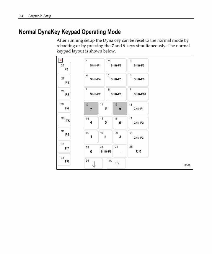
Normal DynaKey Keypad Operating Mode After running setup the DynaKey can be reset to the normal mode by rebooting or by pressing the 7 and 9 keys simultaneously. The normal keypad layout is shown below.
12389
Shift-F31 2 3
4 5 6
7 8 9
Shift-F2Shift-F1
Shift-F4 Shift-F5 Shift-F6
987
4 5 6
1 2 318 19 20 21
14 15 16 17
10 11 12 13
0 CR22 23 24 25
Shift-F7 Shift-F8 Shift-F10
Cntl-F1
Cntl-F2
Cntl-F3
.Shift-F9
3534
F1
F2
26
27
28
29
30
31
33
F3
F4
F5
F6
F8
32F7
Chapter 3: Setup 3-5
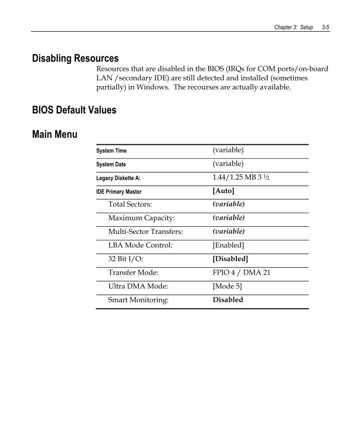
Disabling Resources Resources that are disabled in the BIOS (IRQs for COM ports/on-board LAN /secondary IDE) are still detected and installed (sometimes partially) in Windows. The recourses are actually available.
BIOS Default Values
Main Menu System Time (variable)
System Date (variable)
Legacy Diskette A: 1.44/1.25 MB 3 ½
IDE Primary Master [Auto]
Total Sectors: (variable)
Maximum Capacity: (variable)
Multi-Sector Transfers: (variable)
LBA Mode Control: [Enabled]
32 Bit I/O: [Disabled]
Transfer Mode: FPIO 4 / DMA 21
Ultra DMA Mode: [Mode 5]
Smart Monitoring: Disabled
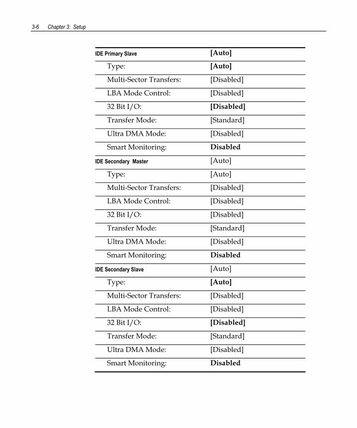
3-6 Chapter 3: Setup
IDE Primary Slave [Auto]
Type: [Auto]
Multi-Sector Transfers: [Disabled]
LBA Mode Control: [Disabled]
32 Bit I/O: [Disabled]
Transfer Mode: [Standard]
Ultra DMA Mode: [Disabled]
Smart Monitoring: Disabled
IDE Secondary Master [Auto]
Type: [Auto]
Multi-Sector Transfers: [Disabled]
LBA Mode Control: [Disabled]
32 Bit I/O: [Disabled]
Transfer Mode: [Standard]
Ultra DMA Mode: [Disabled]
Smart Monitoring: Disabled
IDE Secondary Slave [Auto]
Type: [Auto]
Multi-Sector Transfers: [Disabled]
LBA Mode Control: [Disabled]
32 Bit I/O: [Disabled]
Transfer Mode: [Standard]
Ultra DMA Mode: [Disabled]
Smart Monitoring: Disabled
Chapter 3: Setup 3-7
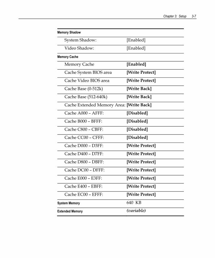
Memory Shadow
System Shadow: [Enabled]
Video Shadow: [Enabled]
Memory Cache
Memory Cache [Enabled]
Cache System BIOS area [Write Protect]
Cache Video BIOS area [Write Protect]
Cache Base (0-512k) [Write Back]
Cache Base (512-640k) [Write Back]
Cache Extended Memory Area: [Write Back]
Cache A000 – AFFF: [Disabled]
Cache B000 – BFFF: [Disabled]
Cache C800 – CBFF: [Disabled]
Cache CC00 – CFFF: [Disabled]
Cache D000 – D3FF: [Write Protect]
Cache D400 – D7FF: [Write Protect]
Cache D800 – DBFF: [Write Protect]
Cache DC00 – DFFF: [Write Protect]
Cache E000 – E3FF: [Write Protect]
Cache E400 – EBFF: [Write Protect]
Cache EC00 – EFFF: [Write Protect]
System Memory 640 KB
Extended Memory (variable)
3-8 Chapter 3: Setup
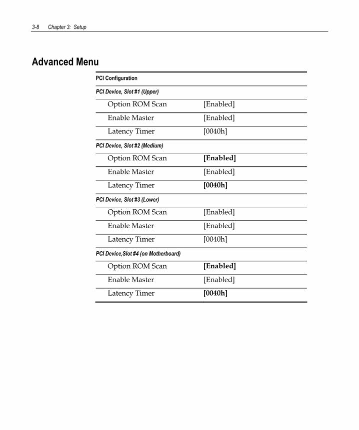
Advanced Menu PCI Configuration
PCI Device, Slot #1 (Upper)
Option ROM Scan [Enabled]
Enable Master [Enabled]
Latency Timer [0040h]
PCI Device, Slot #2 (Medium)
Option ROM Scan [Enabled]
Enable Master [Enabled]
Latency Timer [0040h]
PCI Device, Slot #3 (Lower)
Option ROM Scan [Enabled]
Enable Master [Enabled]
Latency Timer [0040h]
PCI Device,Slot #4 (on Motherboard)
Option ROM Scan [Enabled]
Enable Master [Enabled]
Latency Timer [0040h]
Chapter 3: Setup 3-9
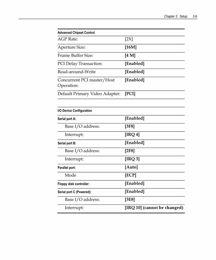
Advanced Chipset Control
AGP Rate: [2X]
Aperture Size: [16M]
Frame Buffer Size: [4 M]
PCI Delay Transaction: [Enabled]
Read-around-Write [Enabled]
Concurrent PCI master/Host Operation:
[Enabled]
Default Primary Video Adapter: [PCI]
I/O Device Configuration
Serial port A: [Enabled]
Base I/O address: [3F8]
Interrupt: [IRQ 4]
Serial port B: [Enabled]
Base I/O address: [2F8]
Interrupt: [IRQ 3]
Parallel port: [Auto]
Mode [ECP]
Floppy disk controller: [Enabled]
Serial port C (Powered): [Enabled]
Base I/O address: [3E8]
Interrupt: [IRQ 10] (cannot be changed)
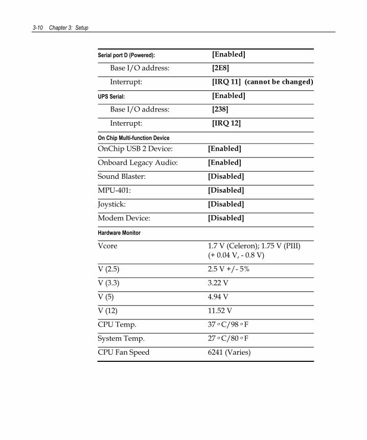
3-10 Chapter 3: Setup
Serial port D (Powered): [Enabled]
Base I/O address: [2E8]
Interrupt: [IRQ 11] (cannot be changed)
UPS Serial: [Enabled]
Base I/O address: [238]
Interrupt: [IRQ 12]
On Chip Multi-function Device
OnChip USB 2 Device: [Enabled]
Onboard Legacy Audio: [Enabled]
Sound Blaster: [Disabled]
MPU-401: [Disabled]
Joystick: [Disabled]
Modem Device: [Disabled]
Hardware Monitor
Vcore 1.7 V (Celeron); 1.75 V (PIII) (+ 0.04 V, - 0.8 V)
V (2.5) 2.5 V +/- 5%
V (3.3) 3.22 V
V (5) 4.94 V
V (12) 11.52 V
CPU Temp. 37 o C/98 o F
System Temp. 27 o C/80 o F
CPU Fan Speed 6241 (Varies)
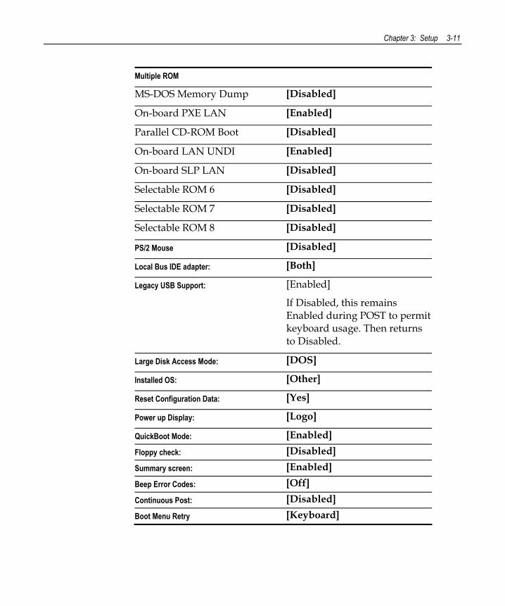
Chapter 3: Setup 3-11
Multiple ROM
MS-DOS Memory Dump [Disabled]
On-board PXE LAN [Enabled]
Parallel CD-ROM Boot [Disabled]
On-board LAN UNDI [Enabled]
On-board SLP LAN [Disabled]
Selectable ROM 6 [Disabled]
Selectable ROM 7 [Disabled]
Selectable ROM 8 [Disabled]
PS/2 Mouse [Disabled]
Local Bus IDE adapter: [Both]
Legacy USB Support: [Enabled]
If Disabled, this remains Enabled during POST to permit keyboard usage. Then returns to Disabled.
Large Disk Access Mode: [DOS]
Installed OS: [Other]
Reset Configuration Data: [Yes]
Power up Display: [Logo]
QuickBoot Mode: [Enabled] Floppy check: [Disabled] Summary screen: [Enabled] Beep Error Codes: [Off] Continuous Post: [Disabled] Boot Menu Retry [Keyboard]
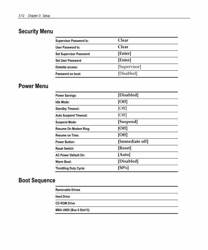
3-12 Chapter 3: Setup
Security Menu Supervisor Password Is: Clear User Password Is: Clear Set Supervisor Password [Enter] Set User Password [Enter] Diskette access: [Supervisor] Password on boot: [Disabled]
Power Menu Power Savings: [Disabled] Idle Mode: [Off] Standby Timeout: [Off] Auto Suspend Timeout: [Off] Suspend Mode: [Suspend] Resume On Modem Ring: [Off] Resume on Time: [Off] Power Button: [Immediate off] Reset Switch: [Reset] AC Power Default On: [Auto] Warm Boot: [Disabled] Throttling Duty Cycle: [50%]
Boot Sequence Removable Drives Hard Drive CD ROM Drive MBA UNDI (Bus 0 Slot13)
Chapter 4: Operating System Recovery
Introduction This chapter discusses procedures on how to recover the Operating System by using the CD-ROM drive. The software is distributed on bootable CD-ROM media. The drivers that are necessary to run the CD-ROM are temporarily installed during boot.
Note: It is possible to perform a BIOS update using a network connection. Refer to the NCR FitClient Software User’s Guide, (B005-0000-1235) for information about that procedure.
Caution: When performing an OS recovery from a larger source image (larger disk) to a smaller destination disk, you must use a special procedure (see the OS Recovery from a Larger Disk Image section).
Prerequisites The following are required in order to perform an OS recovery from a CD.
• Bootable CD-ROM drive (internal or external)
• Keyboard
• CD containing Operating System image
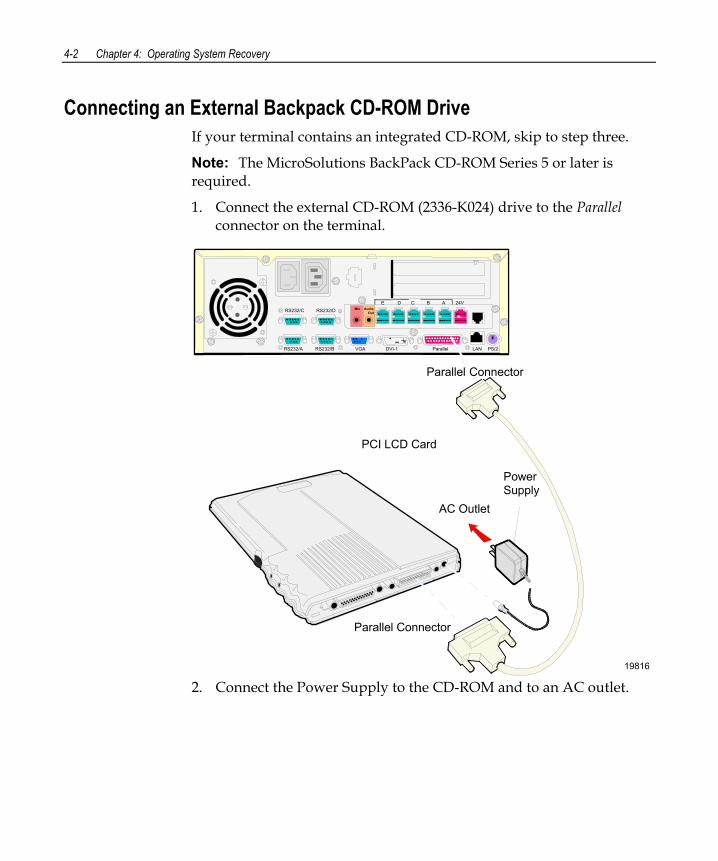
4-2 Chapter 4: Operating System Recovery
Connecting an External Backpack CD-ROM Drive If your terminal contains an integrated CD-ROM, skip to step three.
Note: The MicroSolutions BackPack CD-ROM Series 5 or later is required.
1. Connect the external CD-ROM (2336-K024) drive to the Parallel connector on the terminal.
19816
Mic Audio Out
E D C B A 24VRS232/C RS232/D
RS232/A RS232/B VGA DVI-1 Parallel LAN PS/2
PCI LCD Card
Parallel Connector
Parallel Connector
Power Supply
AC Outlet
2. Connect the Power Supply to the CD-ROM and to an AC outlet.
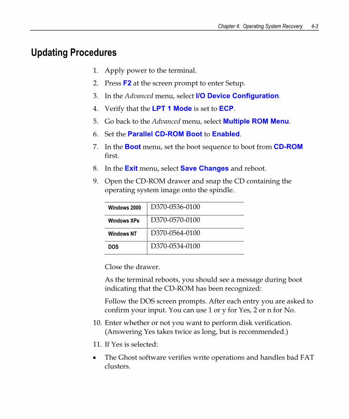
Chapter 4: Operating System Recovery 4-3
Updating Procedures 1. Apply power to the terminal.
2. Press F2 at the screen prompt to enter Setup.
3. In the Advanced menu, select I/O Device Configuration.
4. Verify that the LPT 1 Mode is set to ECP.
5. Go back to the Advanced menu, select Multiple ROM Menu.
6. Set the Parallel CD-ROM Boot to Enabled.
7. In the Boot menu, set the boot sequence to boot from CD-ROM first.
8. In the Exit menu, select Save Changes and reboot.
9. Open the CD-ROM drawer and snap the CD containing the operating system image onto the spindle.
Windows 2000 D370-0536-0100
Windows XPe D370-0570-0100
Windows NT D370-0564-0100
DOS D370-0534-0100
Close the drawer.
As the terminal reboots, you should see a message during boot indicating that the CD-ROM has been recognized:
Follow the DOS screen prompts. After each entry you are asked to confirm your input. You can use 1 or y for Yes, 2 or n for No.
10. Enter whether or not you want to perform disk verification. (Answering Yes takes twice as long, but is recommended.)
11. If Yes is selected:
• The Ghost software verifies write operations and handles bad FAT clusters.

4-4 Chapter 4: Operating System Recovery
• The Ghost error file (GHOST.ERR) is displayed before rebooting.
Chapter 4: Operating System Recovery 4-5
12. If No is selected:
• The Ghost error file is displayed before rebooting only if Ghost aborts.
Caution: If the error file is displayed, the batch file pauses for user input before rebooting. You may use Ctrl-C to cancel out of the batch file if you want to see the error file again, but nothing should be done that writes to the hard disk before rebooting. GHOST.ERR is on the RAM disk and is lost on reboot.
13. Select which type of recovery you want to perform from the next menu and press [ENTER] (normally option #1). 1) Redo entire disk with the first partition the same size.
2) Redo the first OS partition.
3) Redo the second OS partition.
The Ghost software then begins the disk recovery from the CD. It displays a progress bar and gives you an estimate how long the process should take.
Note: Some Operating Systems occupy more than one CD. You are asked to insert the next CD at the proper time.
When the recovery process is completed, the hard disk has been restored to its preinstalled condition, as originally received from the factory.
14. Remove the CD from the drive.
15. Enter Setup when the terminal reboots and reset the Parallel CD-ROM Boot to Disabled.
16. Exit Setup and Save Changes.
4-6 Chapter 4: Operating System Recovery
Completing the OS Installation (Windows 2000) The system automatically reboots when the image recovery is complete and starts the software installation. This installation also installs most of the additional software and drivers that are included in the disk image. Complete the installation as follows.
1. Accept the license agreement.
2. Enter the User Name and Organization.
3. Enter the Computer Name for the client.
4. Enter the Administrator’s Account Password (optional)
5. Login when prompted after the reboot.
6. Run the TouchWare calibration from the Desktop icon (if using a touch screen).
Completing the OS Installation (Windows NT 4.0) The system automatically reboots when the image recovery is complete and starts the software installation. This installation also installs most of the additional software and drivers that are included in the disk image.
Note: The mouse port is disabled. You must use the keyboard to complete the installation. The mouse can be enabled later.
Complete the installation as follows.
1. Press [ENTER] to start Windows NT Setup.
2. Enter the User Name and Organization.
3. Enter the Computer Name for the client.
4. Enter the Administrator’s Account Password (optional)
5. Press [ENTER] to reboot.
6. Login when prompted.
7. Run the TouchWare calibration from the Desktop icon (if using a touch screen).
Chapter 4: Operating System Recovery 4-7
Completing the OS Installation (Windows EXe) The system automatically reboots when the image recovery is complete and opens at the Welcome screen.
Completing the OS Installation (DOS) The system automatically reboots when the image recovery is complete and opens at the DOS C:\ prompt.
4-8 Chapter 4: Operating System Recovery
Gold Disk Contents This section describes the contents of each of the Gold Disk Images, including all the additions and changes that were installed on top of the generic operating system.
NCR 7456/58 Windows 2000 Operating System Recovery Software (LPIN: D370-0536-0100)
The NCR 7456/58 Windows 2000 Operating System Recovery Software provides the means of restoring the operating system to the terminal hard disk to the preinstalled state as shipped from the factory.
Installed Software: • Microsoft Windows 2000 Professional w/ SP3
• Microsoft Internet Explorer 6.0 SP1 (6.0.2800.1106 SP1)
• VIA Tech Video (6.13.10.3137)
• VIA AC'97 Audio (5.12.01.3811)
• National Semiconductor LAN (5.00.135.21)
• NCRSYSM (3.0.4.12)
• Windows Installer (2.0)
• UDMA 4-in-1 (4.43)
• Backpack CD-Rom available (3.02)
• MicroTouch available (5.64)
• Edgeport USB available (2.20)
• C&T Video available
Chapter 4: Operating System Recovery 4-9
Software Drivers The following drivers are not installed automatically, but can be installed from their respective locations (Readme files exist in these locations, as well):
• Backpack CD-ROM C:\Install\Drivers\CDROM
• MicroTouch C:\Install\Drivers\Touch
• Edgeport USB C:\Install\Drivers\USB • C&T Video C:\Install|Drivers\Video
Special Settings Furthermore, the following settings/revisions are configured:
• Preinstalled W2K to include the Product ID Number (PID)
• Placed the Gold Drive Part Number, Date Created, LPIN, and Release in Registry under:
HKey-Local_Machine\Software\NCR\Gold Drive
• Ran Sysprep, using sysprep.inf and sysprep.bat, so that the mini installation runs on initial boot with the following parameters:
- Automatically include PID
• Established a FAT32 primary system partition that fills the entire drive
• Included necessary OS cab files in C:\Install
• Made SP3 folder available in C:\Install (installed)
• Enabled DMA
• Set color to 16 bit
• Set monitor shutoff to Never
• Added SNMP, set to manual
4-10 Chapter 4: Operating System Recovery
• Added registry value for Orinoco PCMCIA driver: HKLM\System\CurrentControlSet\Services\PCMCIA\ Parameters\DisableIsaToPciRouting DWORD Value = 0
Note: This product should only be used on NCR 7458 terminals with a Microsoft Windows 2000 license.
Recommendation For each operating system, NCR strongly recommends that any drivers placed in the C:\Install directory be left intact for the purposes of servicing and maintaining the system. If you are using this information in order to build your own operating system image and not using NCR’s provided OS Recovery image as a base image, we recommend that all drivers that are installed be placed in a similar C:\Install directory for support.
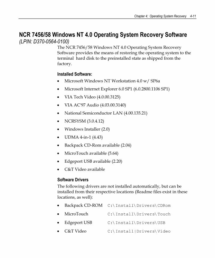
Chapter 4: Operating System Recovery 4-11
NCR 7456/58 Windows NT 4.0 Operating System Recovery Software (LPIN: D370-0564-0100)
The NCR 7456/58 Windows NT 4.0 Operating System Recovery Software provides the means of restoring the operating system to the terminal hard disk to the preinstalled state as shipped from the factory.
Installed Software: • Microsoft Windows NT Workstation 4.0 w/ SP6a
• Microsoft Internet Explorer 6.0 SP1 (6.0.2800.1106 SP1)
• VIA Tech Video (4.0.00.3125)
• VIA AC'97 Audio (4.03.00.3140)
• National Semiconductor LAN (4.00.135.21)
• NCRSYSM (3.0.4.12)
• Windows Installer (2.0)
• UDMA 4-in-1 (4.43)
• Backpack CD-Rom available (2.04)
• MicroTouch available (5.64)
• Edgeport USB available (2.20)
• C&T Video available
Software Drivers The following drivers are not installed automatically, but can be installed from their respective locations (Readme files exist in these locations, as well):
• Backpack CD-ROM C:\Install\Drivers\CDRom
• MicroTouch C:\Install\Drivers\Touch
• Edgeport USB C:\Install\Drivers\USB
• C&T Video C:\Install|Drivers\Video
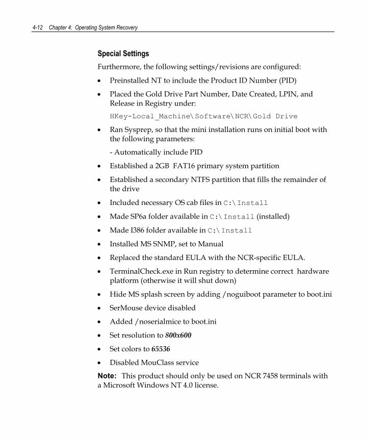
4-12 Chapter 4: Operating System Recovery
Special Settings Furthermore, the following settings/revisions are configured:
• Preinstalled NT to include the Product ID Number (PID)
• Placed the Gold Drive Part Number, Date Created, LPIN, and Release in Registry under:
HKey-Local_Machine\Software\NCR\Gold Drive
• Ran Sysprep, so that the mini installation runs on initial boot with the following parameters:
- Automatically include PID
• Established a 2GB FAT16 primary system partition
• Established a secondary NTFS partition that fills the remainder of the drive
• Included necessary OS cab files in C:\Install
• Made SP6a folder available in C:\Install (installed)
• Made I386 folder available in C:\Install
• Installed MS SNMP, set to Manual
• Replaced the standard EULA with the NCR-specific EULA.
• TerminalCheck.exe in Run registry to determine correct hardware platform (otherwise it will shut down)
• Hide MS splash screen by adding /noguiboot parameter to boot.ini
• SerMouse device disabled
• Added /noserialmice to boot.ini
• Set resolution to 800x600
• Set colors to 65536
• Disabled MouClass service
Note: This product should only be used on NCR 7458 terminals with a Microsoft Windows NT 4.0 license.
Chapter 4: Operating System Recovery 4-13
Recommendation For each operating system, NCR strongly recommends that any drivers placed in the C:\Install directory be left in tack for the purposes of servicing and maintaining the system. If you are using this information in order to build your own operating system image and not using NCR's provided OS Recovery image as a base image, we recommend that all drivers that are installed be placed in a similar C:\Install directory for support.
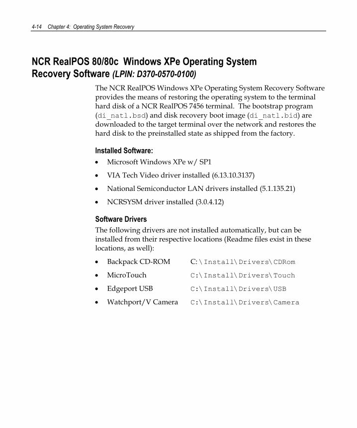
4-14 Chapter 4: Operating System Recovery
NCR RealPOS 80/80c Windows XPe Operating System Recovery Software (LPIN: D370-0570-0100)
The NCR RealPOS Windows XPe Operating System Recovery Software provides the means of restoring the operating system to the terminal hard disk of a NCR RealPOS 7456 terminal. The bootstrap program (di_natl.bsd) and disk recovery boot image (di_natl.bid) are downloaded to the target terminal over the network and restores the hard disk to the preinstalled state as shipped from the factory.
Installed Software: • Microsoft Windows XPe w/ SP1
• VIA Tech Video driver installed (6.13.10.3137)
• National Semiconductor LAN drivers installed (5.1.135.21)
• NCRSYSM driver installed (3.0.4.12)
Software Drivers The following drivers are not installed automatically, but can be installed from their respective locations (Readme files exist in these locations, as well):
• Backpack CD-ROM C: \Install\Drivers\CDRom
• MicroTouch C:\Install\Drivers\Touch
• Edgeport USB C:\Install\Drivers\USB
• Watchport/V Camera C:\Install\Drivers\Camera
Chapter 4: Operating System Recovery 4-15
Special Settings Furthermore, the following settings/revisions are configured:
• Preinstalled XPe to include the Product ID Number (PID)
• Placed the Gold Drive Part Number, Date Created, LPIN, and Release in Registry under:
HKey-Local_Machine\Software\NCR\Gold Drive
• Established a NTFS primary system partition that fills the entire drive
• Installed Via 4in1 Driver set (4.43)
• Installed Via Video Driver (6.13.10.3137)
• Set virtual memory to 128
• Added NetSetUp.exe to RunOnce registry
• Added NCR-specific EULA
Note: This product should only be used on NCR RealPOS 80/80c terminals with a Microsoft Windows XPe license.
Recommendation For each operating system, NCR strongly recommends that any drivers placed in the C:\Install directory be left intact for the purposes of servicing and maintaining the system. If you are using this information in order to build your own operating system image and not using NCR’s provided OS Recovery image as a base image, we recommend that all drivers that are installed be placed in a similar C:\Install directory for support.
4-16 Chapter 4: Operating System Recovery
OS Recovery from a Larger Disk Image The following procedure should be used to restore an Operating System when the destination disk is smaller than the source image (i.e. OS Recovery was made on a 10 GB source disk, but is being recovered on a 4.3 GB drive).
1. Boot the system.
You should see a message during boot indicating that the CD-ROM has been recognized: Micro Solutions BACKPACK CD-ROM v0.3 . . . Booting from BACKPACK CD Starting MS-DOS
2. Follow the DOS screen prompts. After each entry, you are asked to confirm your input. You can use 1 or y for Yes, 2 or n for No.
3. Enter No at the Disk verification question.
4. Select which type of recovery you want to perform from the next menu (normally option #1).
1) Redo entire disk with the first partition the same size.
2) Redo the first OS partition.
3) Redo the second OS partition.
5. At the Press any key to continue dialog box, press [CTRL]-C to abort the process. When asked Terminate batch job? Answer Y.
6. From the command prompt, change to drive Z, which is the location of the Ghost software (CD-ROM drive).
7. Run the Ghost command.
Ghost.exe
8. Press Enter.
9. Select Local → Disk → From Image and press Enter.
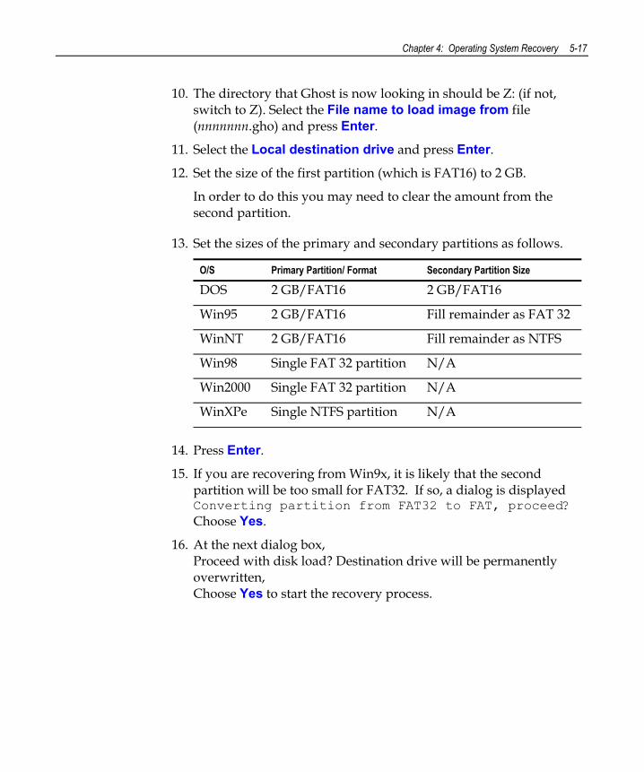
Chapter 4: Operating System Recovery 5-17
10. The directory that Ghost is now looking in should be Z: (if not, switch to Z). Select the File name to load image from file (nnnnnnn.gho) and press Enter.
11. Select the Local destination drive and press Enter.
12. Set the size of the first partition (which is FAT16) to 2 GB.
In order to do this you may need to clear the amount from the second partition.
13. Set the sizes of the primary and secondary partitions as follows.
O/S Primary Partition/ Format Secondary Partition Size
DOS 2 GB/FAT16 2 GB/FAT16
Win95 2 GB/FAT16 Fill remainder as FAT 32
WinNT 2 GB/FAT16 Fill remainder as NTFS
Win98 Single FAT 32 partition N/A
Win2000 Single FAT 32 partition N/A
WinXPe Single NTFS partition N/A
14. Press Enter.
15. If you are recovering from Win9x, it is likely that the second partition will be too small for FAT32. If so, a dialog is displayed Converting partition from FAT32 to FAT, proceed? Choose Yes.
16. At the next dialog box, Proceed with disk load? Destination drive will be permanently overwritten, Choose Yes to start the recovery process.
5-18 Chapter 5: BIOS Updating Procedures
Chapter 5: BIOS Updating Procedures
Introduction This chapter discusses procedures how to update the terminal BIOS by using the parallel CD-ROM drive. The software is distributed on bootable CD-ROM media. The drivers that are necessary to run the CD-ROM are temporarily installed during boot.
It is also possible to perform a BIOS update using a network connection. Refer to the NCR FitClient Software User’s Guide (B005-0000-1235) for information about that procedure.
Crisis Recovery In the event the BIOS becomes corrupt, such as the result of a power failure during the BIOS Update procedure, you can use the method discussed later in this chapter in the BIOS Crisis Recovery section to recover the BIOS.
Prerequisites The following are required on the RealPOS 80c in order to perform a BIOS update using a CD.
• Bootable CD-ROM drive (2336-K024)
• Keyboard
• NCR BIOS and BIOS Update Software (LPIN: A370-0022-0100)
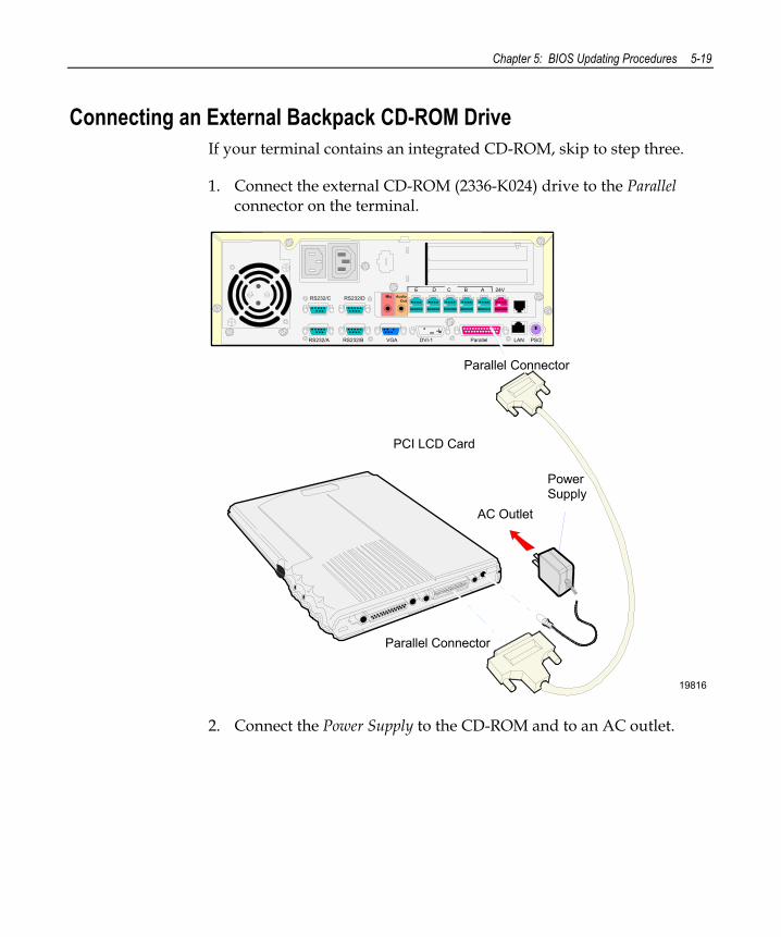
Chapter 5: BIOS Updating Procedures 5-19
Connecting an External Backpack CD-ROM Drive If your terminal contains an integrated CD-ROM, skip to step three.
1. Connect the external CD-ROM (2336-K024) drive to the Parallel connector on the terminal.
19816
Mic Audio Out
E D C B A 24VRS232/C RS232/D
RS232/A RS232/B VGA DVI-1 Parallel LAN PS/2
PCI LCD Card
Parallel Connector
Parallel Connector
Power Supply
AC Outlet
2. Connect the Power Supply to the CD-ROM and to an AC outlet.
5-20 Chapter 5: BIOS Updating Procedures
Updating Procedures 1. Apply power to the terminal.
2. Press F2 at the screen prompt to enter Setup.
3. In the Advanced menu, select I/O Device Configuration.
4. Verify that the LPT 1 Mode is set to ECP.
5. Go back to the Advanced menu, select Multiple ROM Menu.
6. Set the Parallel CD-ROM Boot to Enabled.
7. In the Exit menu, select Save Changes and reboot.
8. Open the CD-ROM drawer and snap the CD containing the BIOS update onto the spindle.
NCR BIOS and BIOS Update Software LPIN: A370-0022-0100
Close the drawer.
As the terminal reboots, you should see a message during boot indicating that the CD-ROM has been recognized: Starting MS-DOS
9. Follow the screen prompts on the client to update the BIOS. You can select two methods to run the update program.
• Automatic BIOS Update – update process runs unattended
Note: You will see a prompt for terminal model and serial number information if the program detects invalid information in the current BIOS, or if you are replacing the processor board, in which case there is no model/serial number information in the BIOS.
Important: Model/Serial Number is mandatory for FitClient operation.
• Interactive BIOS Update – permits you to input/replace the model/serial number information that is stored in the BIOS.
Chapter 5: BIOS Updating Procedures 5-21
Note: Model/Serial number data that is currently stored in the BIOS is displayed during power up.
10. You should see a green window, indicating a successful update.
11. Remove the CD.
12. Press any key to reboot.
13. When the system reboots, press F2 at the screen prompt to enter Setup.
14. In the Exit menu, select Load Setup Defaults.
15. Go to the Advanced menu and set Reset Configuration Data to [Yes].
16. Exit Setup and Save Changes.
5-22 Chapter 5: BIOS Updating Procedures
BIOS Crisis Recovery The procedures below provide a way to restore the BIOS resulting from a non-recoverable condition.
Note: Use this BIOS crisis recovery procedure only for a NON-RECOVERABLE BIOS failure. A non-recoverable BIOS state typically results from power loss during a flash BIOS update process. This is a rare occurrence and should not be confused with other hardware errors that cause a no video state. This procedure is not intended to be used for changing or upgrading an operational BIOS.
Required Hardware
Part Number Part Name Use
PC with an RS-232 port Download BIOS
497-0408349 Cable, 9-Pin Female to 9-Pin Female RS232
PC to terminal connection
497-0413418 Parallel Dongle Forces BIOS recovery
Required Software Acquire the following software from NCR.
NCR 74xx BIOS and BIOS Update Software LPIN: A370-0022-0100, Release 3.0 or later P/N: 497-0424310
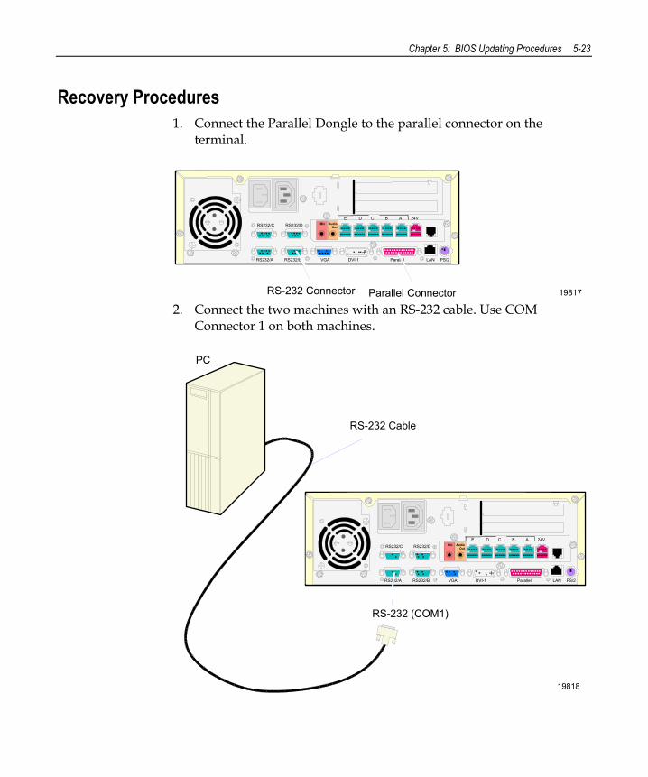
Chapter 5: BIOS Updating Procedures 5-23
Recovery Procedures 1. Connect the Parallel Dongle to the parallel connector on the
terminal.
Mic Audio Out
E D C B A 24VRS232/C RS232/D
RS232/A RS232/B VGA DVI-1 Parallel LAN PS/2
19817Parallel ConnectorRS-232 Connector 2. Connect the two machines with an RS-232 cable. Use COM
Connector 1 on both machines.
19818
PC
RS-232 Cable
Mic Audio Out
E D C B A 24VRS232/C RS232/D
RS232/A RS232/B VGA DVI-1 Parallel LAN PS/2
RS-232 (COM1)
5-24 Chapter 5: BIOS Updating Procedures
3. Boot the PC in the DOS mode with CD-ROM support.
Note: The PC must be running in the DOS mode (not in a Windows DOS box) for the software to operate correctly.
4. Insert the BIOS update CD into the PC.
NCR BIOS and BIOS Update Software LPIN: A370-0022-0100
5. Apply power to the terminal.
6. On the PC, change directory to the CD-ROM drive. E: [Enter]
7. Enter the update command: EMBflash [Enter]
8. Select the number for the 7456minal from the menu list: 1) 7454 2) 7401 3) 7452 4) 7453 5) 7455 6) 7456 7) 7460 8) 7451 9) 7458 6 [Enter]

Chapter 5: BIOS Updating Procedures 5-25
A blue screen displays as the program runs, showing the program progress, followed by a green screen, indicating a successful load.
PhoenixPhlash Status
PRESS ANY KEY TO EXIT
Flash memory has been successfully programmed
19502 The Class/Model/Serial # information is deleted using the Crisis Recovery procedure.
Use the normal BIOS update procedures as discussed earlier in this chapter to restore the information.
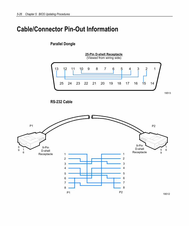
5-26 Chapter 5: BIOS Updating Procedures
Cable/Connector Pin-Out Information
Parallel Dongle
19513
25-Pin D-shell Receptacle(Viewed from wiring side)
25 24 23 22 21 20 19 18 17 16 15 14
13 12 11 10 9 8 7 5 4 3 2 16
RS-232 Cable
19512
12
34
567
8
12
34
567
8
P1 P2
9-PinD-shell
Receptacle16
59
P1 P2
165
9
9-PinD-shell
Receptacle

Chapter 5: BIOS Updating Procedures 5-27

Chapter 6: Memory Dump
General Memory Dump Information In the event of a catastrophic software failure (system lock up), the 7456 provides a means to dump the contents of the system memory contents (RAM) to a file that can then be analyzed using the Memory Dump Analyzer Utility.
In order to get a memory dump on the 7456 it must first be configured in BIOS Setup and/or the Operating System.
Note: The memory dump file is intended to be analyzed by Microsoft or requires a certain level of Post Mortem expertise.
BIOS Requirements The 7456 Memory Dump ROM’s image is contained in the BIOS and can be updated by the BIOS Phlash update Process/Utilities. See the BIOS Updating Procedures chapter.
Memory Dump capability on the 7456 requires NCR BIOS version 3.0.0.0 (or greater).
Disk Format The Memory Dump ROM writes the data to the diskette in the form of a binary FAT compatible file. The ROM directly writes the FAT table information required to permit DOS to interpret the file as a normal binary file. Each diskette receives a single file named dumpinfo.xxx. The extension .xxx is a number denoting the sequential position of the diskette in the consolidated dump image. This extension starts at 001 and increments with each additional diskette used.
Note: All pre-existing data on the diskette is overwritten during the dump process.

6-2 Chapter 6: Memory Dump
Each diskette’s dumpinfo.xxx file is created with the same time and date information to help designate a diskette as being part of a specific set.
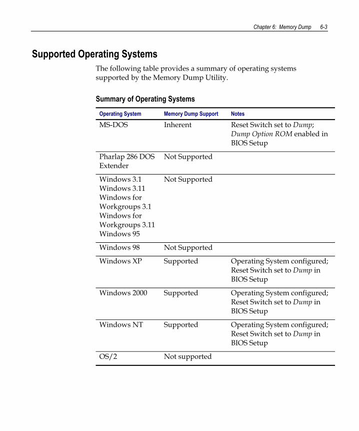
Chapter 6: Memory Dump 6-3
Supported Operating Systems The following table provides a summary of operating systems supported by the Memory Dump Utility.
Summary of Operating Systems
Operating System Memory Dump Support Notes
MS-DOS Inherent Reset Switch set to Dump; Dump Option ROM enabled in BIOS Setup
Pharlap 286 DOS Extender
Not Supported
Windows 3.1 Windows 3.11 Windows for Workgroups 3.1 Windows for Workgroups 3.11 Windows 95
Not Supported
Windows 98 Not Supported
Windows XP Supported Operating System configured; Reset Switch set to Dump in BIOS Setup
Windows 2000 Supported Operating System configured; Reset Switch set to Dump in BIOS Setup
Windows NT Supported Operating System configured; Reset Switch set to Dump in BIOS Setup
OS/2 Not supported
6-4 Chapter 6: Memory Dump
Prerequisites Windows 2000 and Windows NT systems require preparation prior to performing a memory dump.
For additional information about Windows Memory dump refer to the Microsoft web site and search their Knowledge Base for the following:
• Windows 2000 Memory Dump Options Overview (Q254649)
• Gathering Blue Screen Information After Memory Dump in Windows 2000 or Windows NT (Q192463)
Windows XP/2000 To enable memory dump on a Windows 2000 system, complete the following steps prior to performing the memory dump:
1. In the Control Panel, click on System. 2. In System Properties, select Advanced and then Startup and
Recovery. 3. Under System Failure, check the following boxes:
- Write an event to the system log - Send an administrative alert - Automatically reboot
4. In Write debugging information select Complete Memory Dump, and in Dump file: enter - C:\Memory.dmp. Note: The size of the memory file can be very large. Therefore, the file should be dumped to the local drive or a network drive and not to diskettes.
5. Check the box - Overwrite any existing files and enter OK. Do not reboot the system yet.
6. Click on START→Run. Enter regedit and click on OK. 7. Go to HKEY_LOCAL_MACHINE\System\CurrentControlSet\
Control\CrashControl. 8. Click on Edit and then on New. 9. Click on DWORD Value and enter NMICrashDump. 10. Highlight NMICrashDump. Click on Edit and then on Modify.
Chapter 6: Memory Dump 6-5
11. Enter a 1 in Value Data and enter OK. 12. Close the Registry editor.
13. Reboot the system for changes to take effect.
Windows NT To enable memory dump on an NT system, complete the following steps prior to performing the memory dump:
1. In the Control Panel, click on System.
2. In System Properties, select Startup/Shutdown.
3. In the Recovery Section and under When a STOP error occurs, do the following, check the boxes − Write an event to the system log − Send an administrative alert − Write debugging information to:
In the box enter the file name and the path to the local drive, example: C:\Memory.dmp Note: The size of the memory file can be very large. Therefore, the file should be dumped to the local drive or a network drive and not to diskettes.
− Overwrite any existing files − Automatically reboot
4. Click on Apply and enter OK. 5. Click on START→Run. Enter regedit and click on OK. 6. Go to HKEY_LOCAL_MACHINE\System\CurrentControlSet\
Control\CrashControl. 7. Click on Edit and then on New. 8. Click on DWORD Value and enter NMICrashDump. 9. Highlight NMICrashDump and in the Edit function. Click on
Modify. 10. Enter a 1 in Value Data and enter OK.
11. Reboot the system for changes to take effect.
6-6 Chapter 6: Memory Dump
DOS Memory Dump Specifics In the event of a catastrophic software failure (system lock up), the 7456 provides a means to dump the contents of the system memory contents (RAM) to a file that can then be analyzed using the Memory Dump Analyzer Utility.
Workstations running MS-DOS are fully supported by the Memory Dump process. No additional runtime software is required.
The Dump Option ROM must be set to [Enabled] in BIOS Setup
Dump Process Overview The memory dump process writes the data onto diskettes. As each diskette is filled, the user is prompted for another. When the memory dump is complete, all diskettes successfully used in the dump denote a set of diskettes that comprise a single consolidated memory dump image. The data from the diskettes is then moved to hard disk and the consolidated dump image file reassembled from its component pieces.
Note: The workstation must remain powered up following the system lock up, before performing the memory dump, else the memory contents will be lost.
Restrictions and Limitations The Memory Dump functionality has the following restrictions and limitations:
• Dumps to flex drive only. No hard disk or LAN support is provided.
• All dumps are written to drive A:
• 1.44 MB diskettes and 12-bit FAT are the only supported media.
• Diskettes must be preformatted.
• Memory between the base 640K and the start of extended memory is not dumped. (A0000h and FFFFFh is not dumped)
Chapter 6: Memory Dump 6-7
• No control header information is added to the diskette dump files. Human error can cause memory dump images to be rebuilt incorrectly. An example would be mixing files from different memory dumps.
• No video or keyboard interaction during the memory dump process is provided. All information is provided to the user by way of speaker tunes and beeps.
• If a protect mode NMI hander is not set up to direct NMIs to the real mode vector captured by the Memory Dump ROM, the system experiences the default protect mode NMI handling defined by the operating system and/or compilers used. Often this is a fatal system error.
• When the dump switch is pressed the signal SERR# is introduced onto the BUS producing a NMI. If the Memory Dump ROM’s NMI handler is not invoked at this time, further activation of the memory dump switch will not produce a NMI as no software has run to re-enable the SERR# signal to produce a NMI. This would only occur in real mode if third party software captured the NMI vector and did not forward it to its previous handler. Under protect mode this can occur if the dump button’s NMI is handled by the default protect mode NMI handler.
• The register contents stored within the pseudo CMOS storage in the resulting dump are those seen at entry to the Memory Dump ROM’s NMI handler and do not specifically match those that would be most useful - those of the application interrupted.
• Intel 386 or higher processor, required as the Memory Dump ROM, is compiled with the .386 option in order to fully save the CPU state.
• Diskette drive must support change line.
• 512 bytes is the only supported sector size. This is the sector size MS-DOS is hard coded throughout to support.
6-8 Chapter 6: Memory Dump
• Corruption of the interrupt vector table will prevent memory dumps from working. If the NMI is not routed through to the ROM, the memory dump process cannot start. The Memory Dump ROM uses several BIOS interrupts to access the diskette, get time and date, and determine the amount of extended memory present. Corruption of the interrupt chain for these BIOS interrupts will prevent memory dumps from working/completing.
• Memory dumps are not supported with Nu-Mega’s Soft-ice or other equivalent programs installed. The ROM’s accessing extended memory for dumping of addresses past the 15.75 MB boundary with Soft-ice 2.80 installed results in Soft-ice popping up and proclaiming a protect violation, failing the dump process.
• Memory dumps initiated while at Nu-Mega Technologies’ Soft-ice prompt will not complete. Soft-ice seems to absorb the NMI when it is active on the screen. When the user exits the debugger and returns to DOS, the dump does not then occur and further depressions of the memory dump switch will not cause a memory dump to start. A NMI occurred due to the dump switch (absorbed by Soft-ice) and no software has run to re-enable further memory dump switch NMIs.
• Installation of Microsoft’s APM module power.exe without enabling the 7456’s PC BIOS APM options may result in failed memory dumps if emm386.exe is also installed. The combination of emm386.exe and power.exe without the BIOS’s APM support enabled causes emm386.exe to take an exception and halt the system when the memory dump button is pushed. emm386.exe displays a message: EMM386 has detected error #13 in an application at memory address 0048:0637. To minimize the chance of data loss, EMM386 has halted your computer. For more information, see the readme.txt file. To restart your computer press ENTER. Users installing power.exe should have the BIOS APM option enabled.
• Windows memory dumps may not always complete.
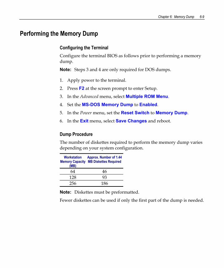
Chapter 6: Memory Dump 6-9
Performing the Memory Dump
Configuring the Terminal Configure the terminal BIOS as follows prior to performing a memory dump.
Note: Steps 3 and 4 are only required for DOS dumps.
1. Apply power to the terminal.
2. Press F2 at the screen prompt to enter Setup.
3. In the Advanced menu, select Multiple ROM Menu.
4. Set the MS-DOS Memory Dump to Enabled.
5. In the Power menu, set the Reset Switch to Memory Dump.
6. In the Exit menu, select Save Changes and reboot.
Dump Procedure The number of diskettes required to perform the memory dump varies depending on your system configuration.
Workstation Memory Capacity
(MB)
Approx. Number of 1.44 MB Diskettes Required
64 46 128 93 256 186
Note: Diskettes must be preformatted.
Fewer diskettes can be used if only the first part of the dump is needed.
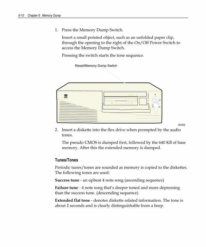
6-10 Chapter 6: Memory Dump
1. Press the Memory Dump Switch.
Insert a small pointed object, such as an unfolded paper clip, through the opening to the right of the On/Off Power Switch to access the Memory Dump Switch.
Pressing the switch starts the tone sequence.
20302
Reset/Memory Dump Switch
2. Insert a diskette into the flex drive when prompted by the audio
tones.
The pseudo CMOS is dumped first, followed by the 640 KB of base memory. After this the extended memory is dumped.
Tunes/Tones Periodic tunes/tones are sounded as memory is copied to the diskettes. The following tones are used:
Success tune - an upbeat 4 note song (ascending sequence)
Failure tune - 4 note song that’s deeper toned and more depressing than the success tune. (descending sequence)
Extended flat tone - denotes diskette related information. The tone is about 2 seconds and is clearly distinguishable from a beep.
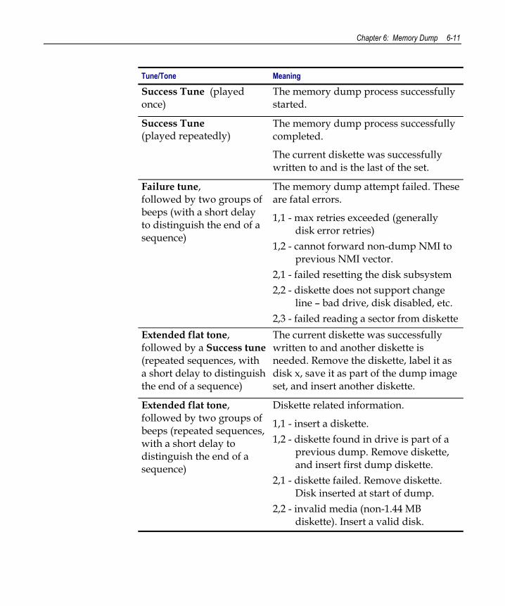
Chapter 6: Memory Dump 6-11
Tune/Tone Meaning
Success Tune (played once)
The memory dump process successfully started.
Success Tune (played repeatedly)
The memory dump process successfully completed.
The current diskette was successfully written to and is the last of the set.
Failure tune, followed by two groups of beeps (with a short delay to distinguish the end of a sequence)
The memory dump attempt failed. These are fatal errors.
1,1 - max retries exceeded (generally disk error retries)
1,2 - cannot forward non-dump NMI to previous NMI vector.
2,1 - failed resetting the disk subsystem 2,2 - diskette does not support change
line – bad drive, disk disabled, etc. 2,3 - failed reading a sector from diskette
Extended flat tone, followed by a Success tune (repeated sequences, with a short delay to distinguish the end of a sequence)
The current diskette was successfully written to and another diskette is needed. Remove the diskette, label it as disk x, save it as part of the dump image set, and insert another diskette.
Extended flat tone, followed by two groups of beeps (repeated sequences, with a short delay to distinguish the end of a sequence)
Diskette related information.
1,1 - insert a diskette. 1,2 - diskette found in drive is part of a
previous dump. Remove diskette, and insert first dump diskette.
2,1 - diskette failed. Remove diskette. Disk inserted at start of dump.
2,2 - invalid media (non-1.44 MB diskette). Insert a valid disk.
6-12 Chapter 6: Memory Dump
Either of the following tones are sounded when a diskette is successfully added to the set of disks composing a memory dump image:
• The Extended tone/Success tune is played, indicating the diskette has been successfully written to and that another diskette is required.
• The Success tune is repeatedly playing, indicating the dump process is complete and the current diskette is the last disk in the set.
Moving the Files to Hard Disk and Reassembling Once the memory dump is complete, you have a set of diskettes, each with a single binary file dumpinfo.xxx. The next step is to move all files on the diskettes to a hard disk. Copy the files to the hard disk using the standard DOS copy command. The copy command MUST have the binary file option /b specified each time it is used.
Note: The amount of hard disk space required to assemble the file is twice the memory dump image size (individual files plus composite image).
After the files are on the hard disk, the DOS utility assemble.exe is run to build the memory dump image from the individual files. The individual diskette files will be left on the hard disk and must be removed manually.
Follow these steps when reassembling the diskettes onto the PC:
1. Change to a directory on the PC that has no other dumpinfo.xxx files. This is important to prevent files from different memory dumps being intermixed.
2. Copy each diskette’s dumpinfo.xxx file to the hard disk using copy /b a:\dumpinfo.*.
3. Reassemble all individual component files into the memory dump image by running assemble.exe.
Note: After assembling the files the image is reassembled and ready for analysis by NCR.
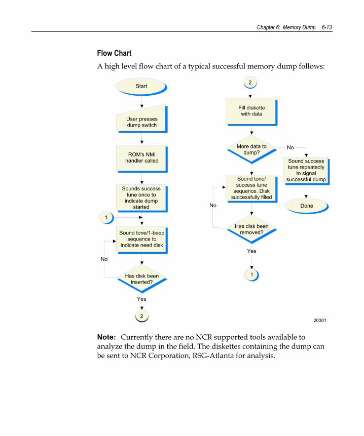
Chapter 6: Memory Dump 6-13
Flow Chart A high level flow chart of a typical successful memory dump follows:
Start
User pressesdump switch
ROM's NMIhandler called
2
Sounds success tune once to
indicate dumpstarted
Sound tone/1-beepsequence to
indicate need disk
Has disk beeninserted?
1
Yes
No
Fill diskettewith data
More data todump?
Sound tone/success tune
sequence. Disksuccessfully filled
Has disk beenremoved?
Sound success tune repeatedly
to signal successful dump
No
Yes
1
2
No Done
20301
Note: Currently there are no NCR supported tools available to analyze the dump in the field. The diskettes containing the dump can be sent to NCR Corporation, RSG-Atlanta for analysis.
6-14 Chapter 6: Memory Dump
Memory Dump Assembler The Memory Dump Assembler is a simple DOS application that reassembles the binary files resulting from a memory dump into a consolidated memory dump image. The utility is part of the Memory Dump Analyzer Utility (497-0406704). The file name is assemble.exe, which is a command line driven application. The command line is: assemble -i <input file’s basename> -o <output file name> where:
• i specifies the basename of the input files (8 characters max). All input files must have the same basename. Do not specify an extension. The default basename is dumpinfo, which is the basename used by the memory dump process.
• o specifies the destination file name. Specify a maximum of twelve characters including the extension, using the FAT 8.3 filename format. The default filename extension is *.dmp.
The diskette files composing the image must be moved manually to an empty subdirectory at a Memory Dump Analyzer workstation. Once all the files are on the hard disk. Run assemble.exe from that directory.
assemble.exe uses all files in the current directory with the configured base name and a numerical extension in the form .001, .002, etc, to build the Memory Dump Analyzer compatible image.
assemble.exe stops when a file with the next sequential extension cannot be located. Use care to not skip any files when moving the diskette files to hard disk. A list of files used in building the image will be displayed upon exit.
Note: The amount of hard disk space required to assemble the file is twice the memory dump image size (individual files plus composite image). The individual diskette files will be left on the hard disk and must be removed manually
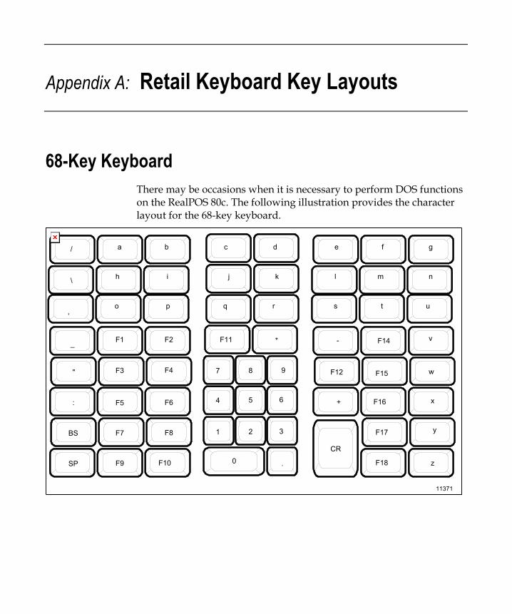
Appendix A: Retail Keyboard Key Layouts
68-Key Keyboard There may be occasions when it is necessary to perform DOS functions on the RealPOS 80c. The following illustration provides the character layout for the 68-key keyboard.
11371
m
a b c d e f g
h i j k l n
o p q r s t u
v
w
x
y
z
/
\
,
_
"
:
BS
SP
F1 F2
F3 F4
F5 F6
F7 F8
F9 F10
F11
F12
F14
F15
F16
F17
F18
+
CR0
1 2 3
4 5 6
7 8 9
* -
.
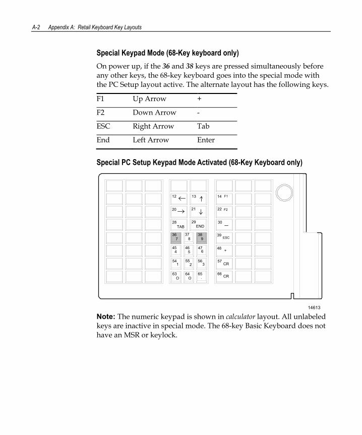
A-2 Appendix A: Retail Keyboard Key Layouts
Special Keypad Mode (68-Key keyboard only) On power up, if the 36 and 38 keys are pressed simultaneously before any other keys, the 68-key keyboard goes into the special mode with the PC Setup layout active. The alternate layout has the following keys.
F1 Up Arrow +
F2 Down Arrow -
ESC Right Arrow Tab
End Left Arrow Enter
Special PC Setup Keypad Mode Activated (68-Key Keyboard only)
14613
12 13 14
20 21 22
28 29 30
36 37 38 39
45 46 47 48
54 55 56
63 64 65 66
57
F1
F2
TAB END
7 8 9 ESC
4 5 6 +
1 2 3 CR
CRO .O
Note: The numeric keypad is shown in calculator layout. All unlabeled keys are inactive in special mode. The 68-key Basic Keyboard does not have an MSR or keylock.
Appendix A: Retail Keyboard Key Layouts A-3
68-Key Keyboard Special Keypad Mode To use the 68-key keyboard to run PC setup routines, the operator can place the keyboard into a special alternate layout mode that replaces the normal layout of the keypad and function keys.
The alternate layout has the following keys:
F1 Up Arrow + F2 Down Arrow - ESC Right Arrow TAB END Left Arrow ENTER
Note: The 68-key keyboard’s special PC Setup mode is provided simply as a convenience feature. If the operator prefers not to use this mode, simply use a PC keyboard for system configuration.
To enter the special PC Setup mode, proceed as follows:
1. Power-up the system.
2. After the memory test completes, hold down key number 36 and key number 38 simultaneously (refer to the keypad layout in this chapter).
Make sure both keys are held down together on the full-featured 68-key keyboard. The status LED flashes red/green to indicate that the keypad entered the PC Setup mode. On the 68-key keyboard with no MSR, the speaker sounds one long beep.
Note: Ignore any stuck key error messages displayed as a result of the keys being held down.
The 36 and 38 keys must be the first two keys pressed after a power-on. If any other keys are pressed first, pressing the 36 and 38 keys simultaneously will not put the 68-key keyboard into the PC Setup mode.
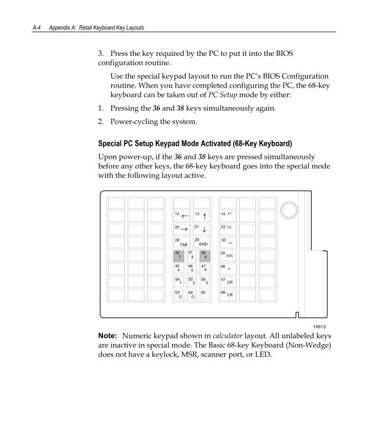
A-4 Appendix A: Retail Keyboard Key Layouts
3. Press the key required by the PC to put it into the BIOS configuration routine.
Use the special keypad layout to run the PC’s BIOS Configuration routine. When you have completed configuring the PC, the 68-key keyboard can be taken out of PC Setup mode by either:
1. Pressing the 36 and 38 keys simultaneously again.
2. Power-cycling the system.
Special PC Setup Keypad Mode Activated (68-Key Keyboard) Upon power-up, if the 36 and 38 keys are pressed simultaneously before any other keys, the 68-key keyboard goes into the special mode with the following layout active.
14613
12 13 14
20 21 22
28 29 30
36 37 38 39
45 46 47 48
54 55 56
63 64 65 66
57
F1
F2
TAB END
7 8 9 ESC
4 5 6 +
1 2 3 CR
CRO .O
Note: Numeric keypad shown in calculator layout. All unlabeled keys are inactive in special mode. The Basic 68-key Keyboard (Non-Wedge) does not have a keylock, MSR, scanner port, or LED.
Appendix A: Retail Keyboard Key Layouts A-5
DynaKey Because many of the terminal setup routines require keys that are not present in the regular DynaKey keypad layout (such as the ESC and END keys), a standard PC keyboard is recommended for completing Setup functions. Although the DynaKey has a PC keyboard connector, a PC keyboard may not be readily available to the operator. If only a DynaKey module is available refer to the text that follows which discusses the special DynaKey mode keypad. Otherwise, proceed to the Configuration Setup Procedures section.
Note: No setup is required for the DynaKey module itself at installation unless the factory default configuration needs changing. The operational parameters can be changed using the Wedge Configuration Utility (LPIN: G370-0701-0000) diskette or the 74xx Diagnostics (P/N: 497-0408905) diskette.
Special DynaKey Keypad Mode To use the DynaKey without a PC keyboard attached to run the terminal setup routines, you must place it in the Special DynaKey Keypad Mode. This mode replaces the normal keypad layout and function keys with special key assignments that are required to run setup. To ENTER the special mode, press the 7 and 9 keys simultaneously during POST diagnostics.
Note: The 7 and 9 keys must be the FIRST keys pressed during or after a power-up; otherwise, the keypad ENTERs the normal layout.
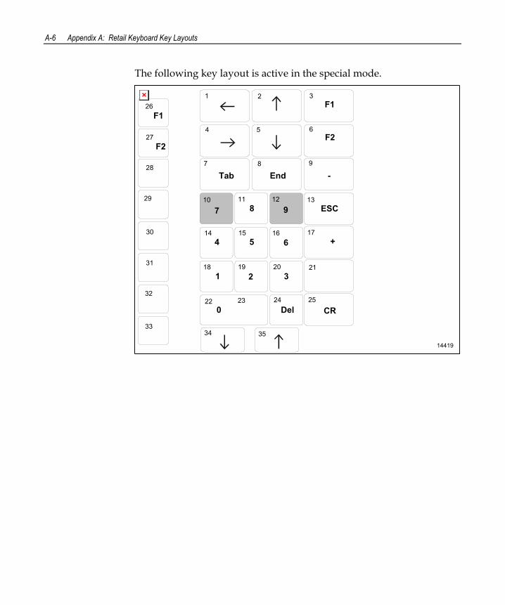
A-6 Appendix A: Retail Keyboard Key Layouts
The following key layout is active in the special mode.
14419
1 2 3
4 5 6
7 8 9
987
4 5 6
1 2 318 19 20 21
14 15 16 17
10 11 12 13
CR22 23 24 25
3534
F1
F2
26
27
28
29
30
31
33
32
F1
F2
ESC
EndTab -
+
0 Del
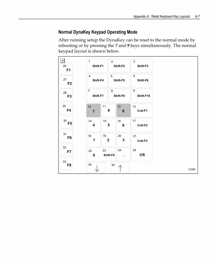
Appendix A: Retail Keyboard Key Layouts A-7
Normal DynaKey Keypad Operating Mode After running setup the DynaKey can be reset to the normal mode by rebooting or by pressing the 7 and 9 keys simultaneously. The normal keypad layout is shown below.
12389
Shift-F31 2 3
4 5 6
7 8 9
Shift-F2Shift-F1
Shift-F4 Shift-F5 Shift-F6
987
4 5 6
1 2 318 19 20 21
14 15 16 17
10 11 12 13
0 CR22 23 24 25
Shift-F7 Shift-F8 Shift-F10
Cntl-F1
Cntl-F2
Cntl-F3
.Shift-F9
3534
F1
F2
26
27
28
29
30
31
33
F3
F4
F5
F6
F8
32F7
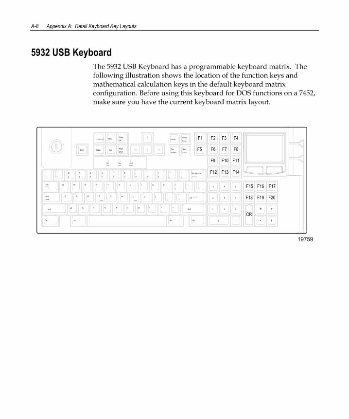
A-8 Appendix A: Retail Keyboard Key Layouts
5932 USB Keyboard The 5932 USB Keyboard has a programmable keyboard matrix. The following illustration shows the location of the function keys and mathematical calculation keys in the default keyboard matrix configuration. Before using this keyboard for DOS functions on a 7452, make sure you have the current keyboard matrix layout.
Down
Page
Up
PagePause
Screen
Lock
Num
Lock
Scroll
0
1
4
7
5
2
6
3
8 9O
<Shift
MNVCX BZ
Ctrl Alt
,
3
#
WQ
Caps
LockSA
1
Tab
~ !
2
@
TRE
D GF
4
$
65
%
IUY
JH K
7
&*
98
(
> ?Shift
Alt
/
Ctrl
CR
P
L
[ ]
0 -
)
=
{ }
+ Backspace
ScrollCapsNumLock Lock Lock
ESC
Home
EndDelete
I n s e r t
19759
F1 F2 F3 F4
F5 F6 F7 F8
F9 F10 F11
F12 F13 F14
F15 F16 F17
F18 F19 F20
+ *
- /CR
Appendix B: Feature Kits
This section contains a comprehensive list of the available hardware Feature Kits that can be installed in the customer environment. Kit installation instructions (for those requiring instruction) are available on the Information Products web sites.
• Internet: http://www.info.ncr.com
• NCR Intranet: http://inforetail.atlantaga.ncr.com
To locate the installation guides on these sites:
1. Select General Search.
2. Select the Kits icon.
3. In the Title field, enter the Kit Title.
Example: Memory
or
In the Product ID field, enter the Kit Number.
Example: 7456-K141
1. Select Search.
The file can be viewed online by left-mouse clicking on the pub title, or if you prefer to download the entire file you can right-mouse click on the title and then a Save target as.
If you aren’t sure of the title or number you can display all kits associated with a terminal product class by:
1. In the Class drop-down list, enter the Class of the terminal.
Example: 7456
2. Select Search.
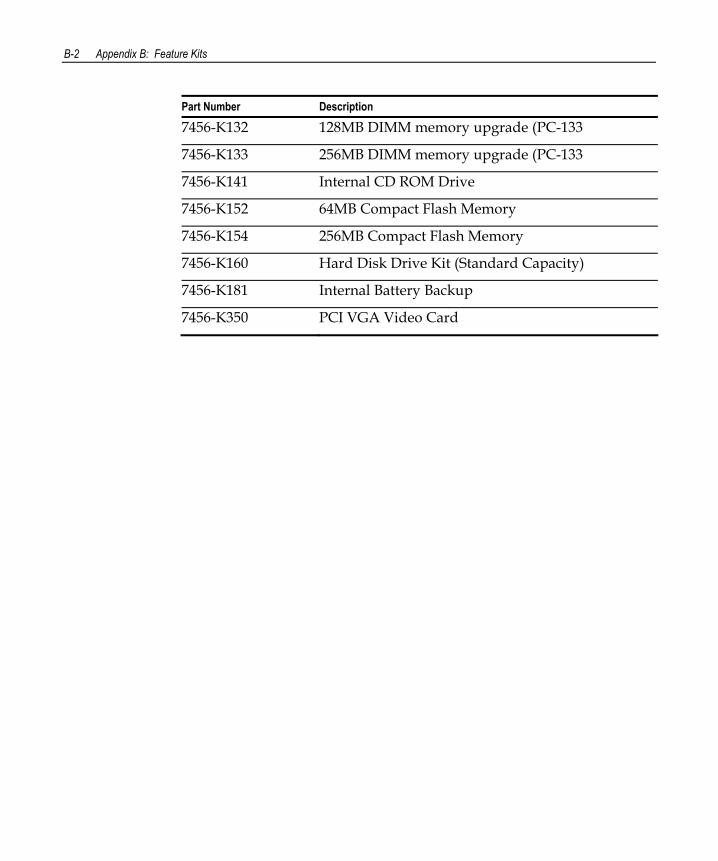
B-2 Appendix B: Feature Kits
Part Number Description
7456-K132 128MB DIMM memory upgrade (PC-133
7456-K133 256MB DIMM memory upgrade (PC-133
7456-K141 Internal CD ROM Drive
7456-K152 64MB Compact Flash Memory
7456-K154 256MB Compact Flash Memory
7456-K160 Hard Disk Drive Kit (Standard Capacity)
7456-K181 Internal Battery Backup
7456-K350 PCI VGA Video Card
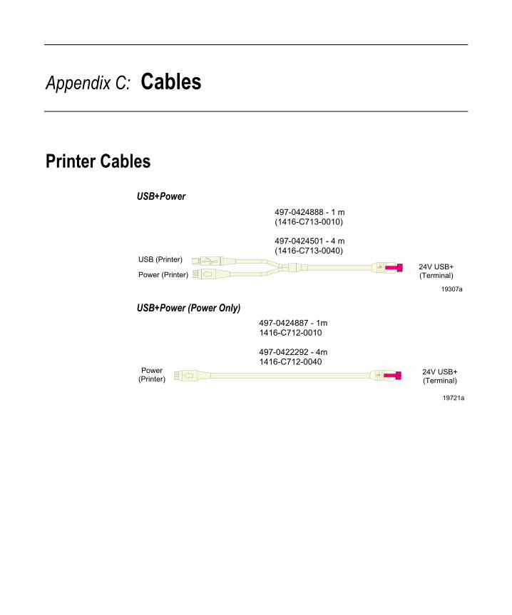
Appendix C: Cables
Printer Cables USB+Power
USB (Printer)24V USB+(Terminal)
497-0424888 - 1 m(1416-C713-0010)
497-0424501 - 4 m(1416-C713-0040)
Power (Printer)
19307a USB+Power (Power Only)
497-0424887 - 1m1416-C712-0010
497-0422292 - 4m1416-C712-0040
19721a
24V USB+(Terminal)
Power(Printer)
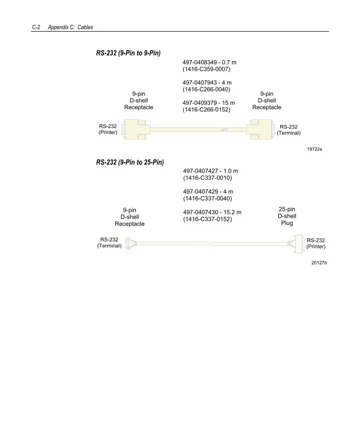
C-2 Appendix C: Cables
RS-232 (9-Pin to 9-Pin)
19722a
9-pinD-shell
Receptacle
9-pinD-shell
Receptacle
497-0408349 - 0.7 m(1416-C359-0007)
497-0407943 - 4 m(1416-C266-0040)
497-0409379 - 15 m(1416-C266-0152)
RS-232(Printer)
RS-232(Terminal)
RS-232 (9-Pin to 25-Pin)
20127b
9-pinD-shell
Receptacle
25-pinD-shell
Plug
497-0407427 - 1.0 m(1416-C337-0010)
497-0407429 - 4 m(1416-C337-0040)
497-0407430 - 15.2 m(1416-C337-0152)
RS-232(Printer)
RS-232(Terminal)
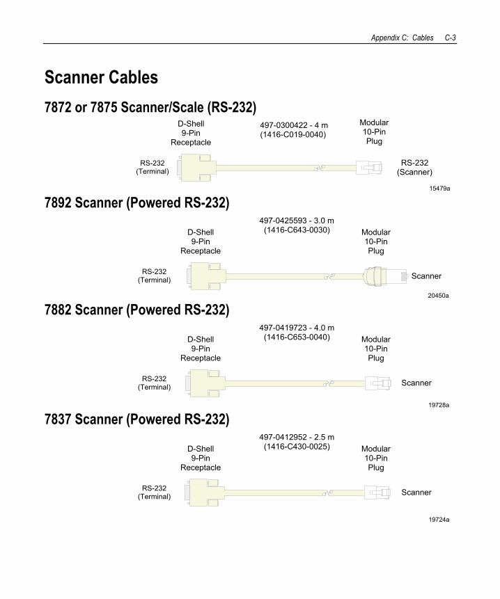
Appendix C: Cables C-3
Scanner Cables 7872 or 7875 Scanner/Scale (RS-232)
15479a
RS-232(Scanner)
D-Shell9-Pin
Receptacle
Modular10-PinPlug
497-0300422 - 4 m(1416-C019-0040)
RS-232(Terminal)
7892 Scanner (Powered RS-232)
20450a
Scanner
D-Shell9-Pin
Receptacle
Modular10-PinPlug
497-0425593 - 3.0 m(1416-C643-0030)
RS-232(Terminal)
7882 Scanner (Powered RS-232)
19728a
Scanner
D-Shell9-Pin
Receptacle
Modular10-PinPlug
497-0419723 - 4.0 m(1416-C653-0040)
RS-232(Terminal)
7837 Scanner (Powered RS-232)
19724a
Scanner
D-Shell9-Pin
Receptacle
Modular10-PinPlug
497-0412952 - 2.5 m(1416-C430-0025)
RS-232(Terminal)
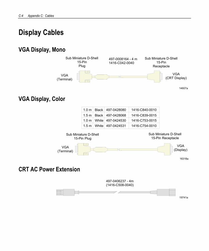
C-4 Appendix C: Cables
Display Cables
VGA Display, Mono
14607a
VGA(CRT Display)
Sub Miniature D-Shell15-PinPlug
497-0008164 - 4 m1416-C042-0040
Sub Miniature D-Shell15-Pin
Receptacle
VGA(Terminal)
VGA Display, Color
16318a
Sub Miniature D-Shell15-Pin Plug
Sub Miniature D-Shell15-Pin Receptacle
VGA(Display)
VGA(Terminal)
497-0428080 1416-C840-00101.0 m Black1.5 m Black1.0 m
White1.5 mWhite
497-0428068 1416-C839-0015497-0424530 1416-C753-0015497-0424531 1416-C754-0010
CRT AC Power Extension
19741a
497-0406237 - 4m(1416-C508-0040)
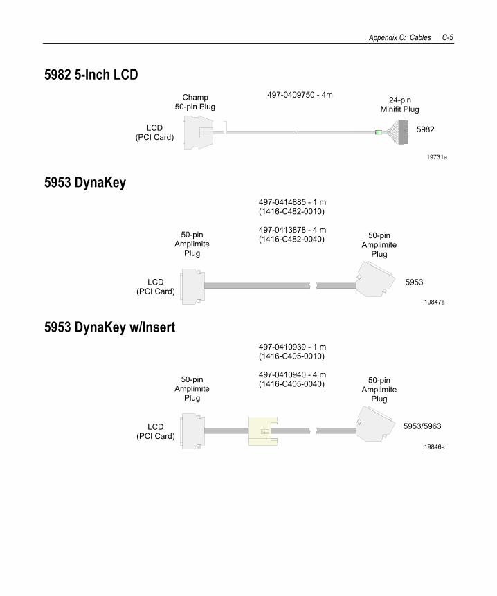
Appendix C: Cables C-5
5982 5-Inch LCD
19731a
LCD(PCI Card)
5982
497-0409750 - 4mChamp50-pin Plug
24-pinMinifit Plug
5953 DynaKey
19847a
5953
50-pinAmplimite
Plug
50-pinAmplimite
Plug
497-0414885 - 1 m(1416-C482-0010)
497-0413878 - 4 m(1416-C482-0040)
LCD(PCI Card)
5953 DynaKey w/Insert
19846a
5953/5963
50-pinAmplimite
Plug
50-pinAmplimite
Plug
497-0410939 - 1 m(1416-C405-0010)
497-0410940 - 4 m(1416-C405-0040)
LCD(PCI Card)
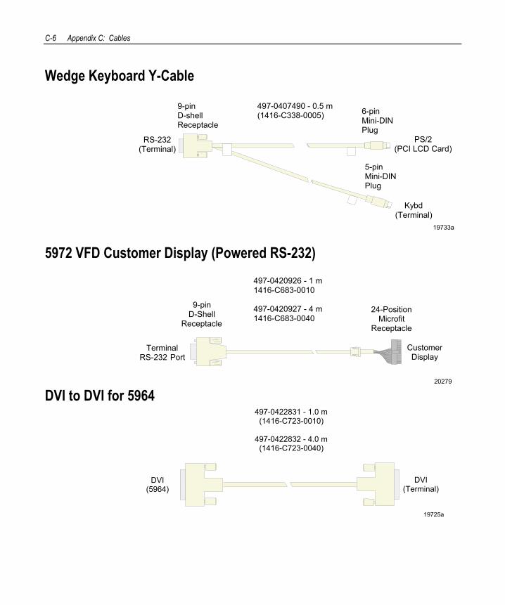
C-6 Appendix C: Cables
Wedge Keyboard Y-Cable
19733a
497-0407490 - 0.5 m(1416-C338-0005)
RS-232(Terminal)
Kybd(Terminal)
6-pinMini-DINPlug
5-pinMini-DINPlug
9-pinD-shellReceptacle
PS/2(PCI LCD Card)
5972 VFD Customer Display (Powered RS-232)
20279
CustomerDisplay
TerminalRS-232 Port
497-0420926 - 1 m1416-C683-0010
497-0420927 - 4 m1416-C683-0040
9-pinD-Shell
Receptacle
24-PositionMicrofit
Receptacle
DVI to DVI for 5964
19725a
497-0422831 - 1.0 m(1416-C723-0010)
497-0422832 - 4.0 m(1416-C723-0040)
DVI(5964)
DVI(Terminal)
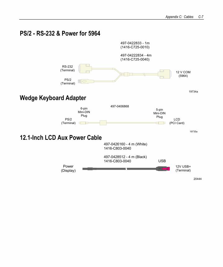
Appendix C: Cables C-7
PS/2 - RS-232 & Power for 5964
RS-232(Terminal) 12 V COM
(5964)
497-0422833 - 1m(1416-C725-0010)
497-04222834 - 4m(1416-C725-0040)
PS/2(Terminal)
19734a Wedge Keyboard Adapter
19735a
497-0406868
PS/2(Terminal)
6-pinMini-DIN
Plug
5-pinMini-DIN
PlugLCD
(PCI Card)
12.1-Inch LCD Aux Power Cable
20444
Power(Display)
497-0426160 - 4 m (White)1416-C803-0040
497-0428512 - 4 m (Black)1416-C803-0040 USB
12V USB+(Terminal)
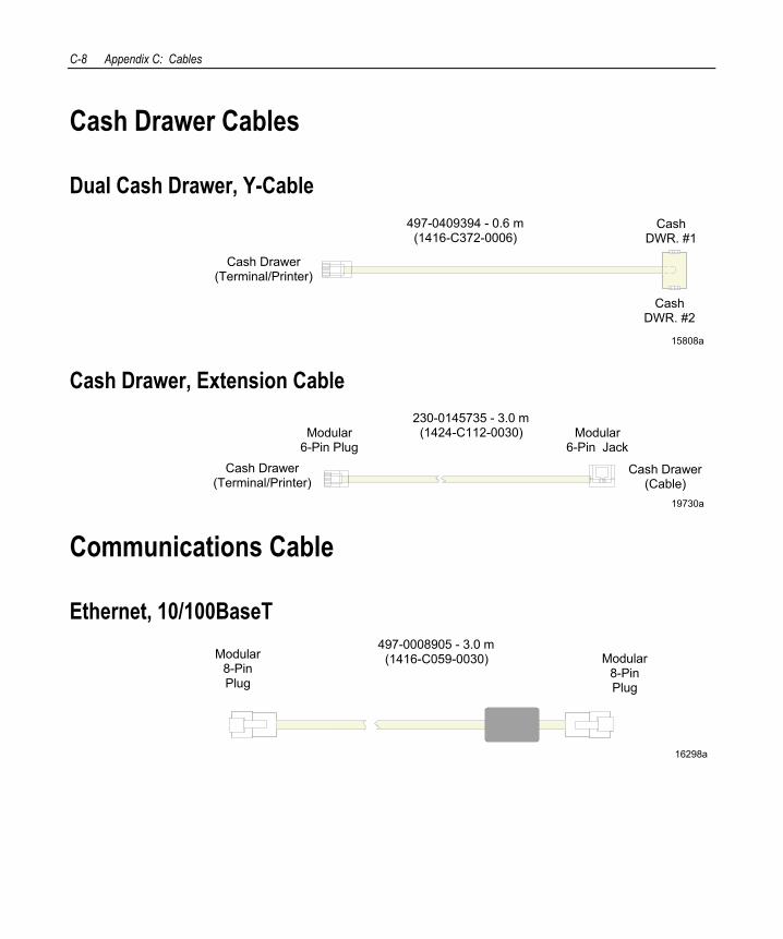
C-8 Appendix C: Cables
Cash Drawer Cables
Dual Cash Drawer, Y-Cable
15808a
497-0409394 - 0.6 m(1416-C372-0006)
CashDWR. #1
CashDWR. #2
Cash Drawer(Terminal/Printer)
Cash Drawer, Extension Cable
19730a
230-0145735 - 3.0 m(1424-C112-0030)
Cash Drawer(Terminal/Printer)
Cash Drawer(Cable)
Modular6-Pin Jack
Modular 6-Pin Plug
Communications Cable
Ethernet, 10/100BaseT
16298a
Modular8-PinPlug
Modular8-PinPlug
497-0008905 - 3.0 m(1416-C059-0030)
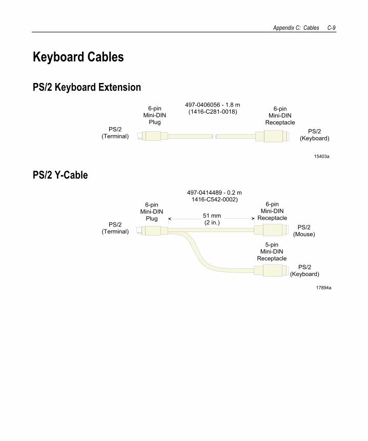
Appendix C: Cables C-9
Keyboard Cables
PS/2 Keyboard Extension
15403a
PS/2(Keyboard)
PS/2(Terminal)
6-pinMini-DIN
Plug
6-pinMini-DIN
Receptacle
497-0406056 - 1.8 m(1416-C281-0018)
PS/2 Y-Cable
17894a
PS/2(Mouse)
PS/2(Terminal)
6-pinMini-DIN
Plug
6-pinMini-DIN
Receptacle
PS/2(Keyboard)
5-pinMini-DIN
Receptacle
51 mm(2 in.)
497-0414489 - 0.2 m1416-C542-0002)
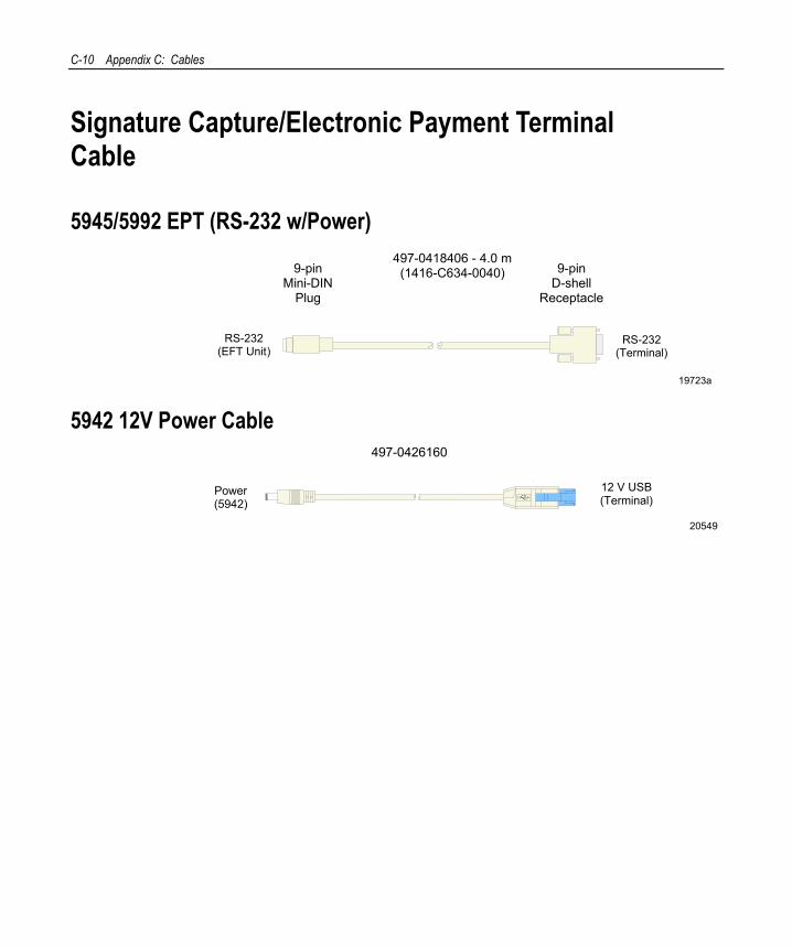
C-10 Appendix C: Cables
Signature Capture/Electronic Payment Terminal Cable
5945/5992 EPT (RS-232 w/Power)
19723a
497-0418406 - 4.0 m(1416-C634-0040) 9-pin
D-shellReceptacle
RS-232(EFT Unit)
RS-232(Terminal)
9-pinMini-DIN
Plug
5942 12V Power Cable 497-0426160
Power(5942)
20549
12 V USB(Terminal)
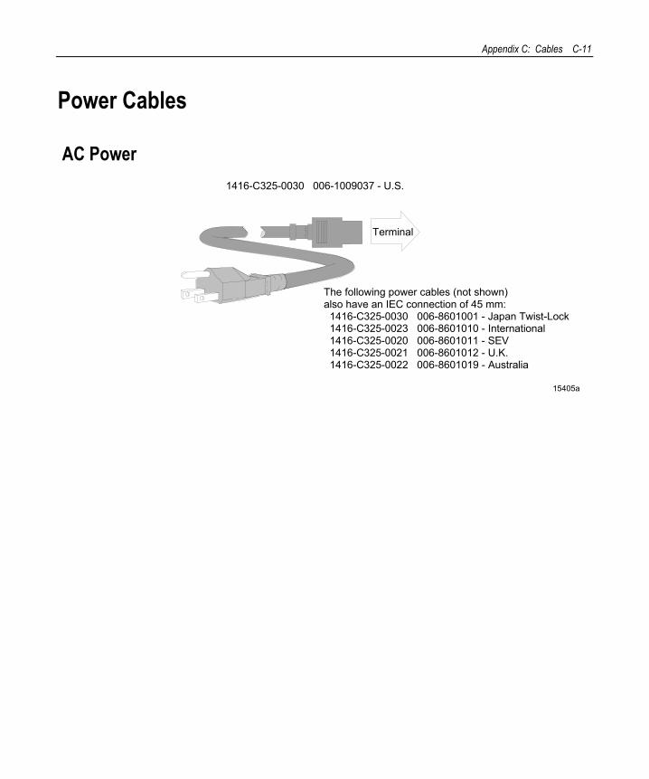
Appendix C: Cables C-11
Power Cables
AC Power
15405a
Terminal
The following power cables (not shown)also have an IEC connection of 45 mm: 1416-C325-0030 006-8601001 - Japan Twist-Lock 1416-C325-0023 006-8601010 - International 1416-C325-0020 006-8601011 - SEV 1416-C325-0021 006-8601012 - U.K. 1416-C325-0022 006-8601019 - Australia
1416-C325-0030 006-1009037 - U.S.

C-12 Appendix C: Cables
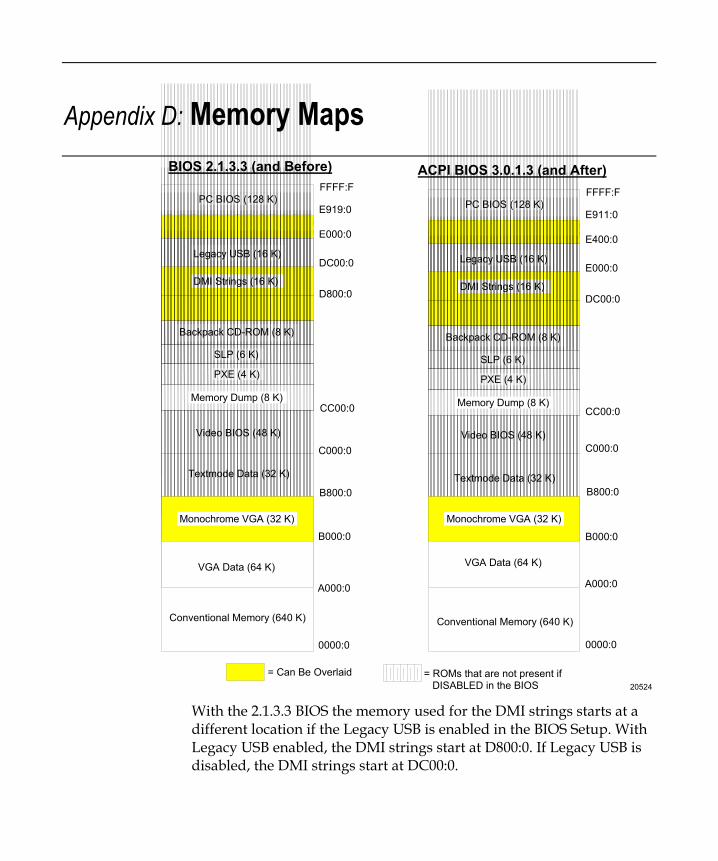
Appendix D: Memory Maps
20524
PC BIOS (128 K)
Legacy USB (16 K)
DMI Strings (16 K)
Backpack CD-ROM (8 K)
Video BIOS (48 K)
Textmode Data (32 K)
SLP (6 K)
PXE (4 K)
Memory Dump (8 K)
VGA Data (64 K)
Conventional Memory (640 K)
Monochrome VGA (32 K)
FFFF:F
E919:0
E000:0
DC00:0
D800:0
CC00:0
C000:0
B800:0
B000:0
A000:0
0000:0
= Can Be Overlaid = ROMs that are not present if DISABLED in the BIOS
BIOS 2.1.3.3 (and Before)
PC BIOS (128 K)
Legacy USB (16 K)
DMI Strings (16 K)
Backpack CD-ROM (8 K)
Video BIOS (48 K)
Textmode Data (32 K)
SLP (6 K)
PXE (4 K)
Memory Dump (8 K)
VGA Data (64 K)
Conventional Memory (640 K)
Monochrome VGA (32 K)
FFFF:F
E911:0
E400:0
E000:0
DC00:0
CC00:0
C000:0
B800:0
B000:0
A000:0
0000:0
ACPI BIOS 3.0.1.3 (and After)
With the 2.1.3.3 BIOS the memory used for the DMI strings starts at a different location if the Legacy USB is enabled in the BIOS Setup. With Legacy USB enabled, the DMI strings start at D800:0. If Legacy USB is disabled, the DMI strings start at DC00:0.
D-2
DOS Considerations For DOS installations, the difference in Upper Memory Blocks may affect how an application loads and operates. If more UMB space is required (and a USB keyboard is not configured), the Legacy USB support should be disabled. In order to get maximum UMB usage, the EMM386.EXE driver should be loaded in the CONFIG.SYS file with the following recommended inclusions and exclusions.
Note: These settings should be validated for the desired workstation configuration and BIOS revision before the system is released.
This EMM386.EXE parameter information assumes you have all ROMs disabled in the BIOS Setup, including the Legacy USB. PXE, SLP, or Backpack CD may be enabled for loading and should not affect memory usage since they are not used during run time. If the memory dump option is enabled, the 8 KB memory area used by this option ROM (X=CC00-CDFF) must be excluded. Any memory used by added adapter cards should also be accounted for with the appropriate exclude parameters. The examples below assume there are no added adapter cards. EMM386 will itself use about 5 KB (5,280 bytes) of the available memory for its own purposes. This 5 KB has not been subtracted from the usable memory totals listed below (140 KB and 144 KB).
The latest BIOS has a starting address for the PC BIOS at E911:0. This address gets lower and lower in the E000 page as new features or corrections are added to the BIOS. With the current BIOS, an Include of I=DD00-E8FF can be used, but doing this risks that a future PC BIOS may become large enough to move into this included area. It is suggested that E3FF be used as a conservative setting if the memory requirements permit it. The smallest amount from the E000 page should be taken, which leaves as much room as possible for the BIOS to grow.
Appendix D: Memory Maps D-3
Non-TAPS DOS Environment For the non-TAPS DOS environment, use EMM386.EXE with the following Include and eXclude parameters to get 144 KB of usable memory:
DEVICE= EMM386.EXE NOEMS I=B000-B7FF X=C000-CBFF ↵ I=CC00-E7FF
I=B000-B7FF – 32 KB This is the VGA Monochrome Text Mode Video RAM area. This assumes that for monochrome text, the VGA Color Text Mode Video RAM with the colors set to black and white is used.
X=C000-CBFF – 48 KB This is the Video BIOS.
I=CC00-E7FF - 112 KB - Available memory
TAPS DOS Environment For a DOS system using TAPS, 140 KB of usable memory is available with the following Include and eXclude parameters:
DEVICE= EMM386.EXE NOEMS I=B000-B7FF X=C000-CBFF ↵ I=CC00-DBFF X=DC00-DCFF I=DD00-E7FF
I=B000-B7FF – 32 KB This is the VGA Monochrome Text Mode Video RAM area. This assumes that for monochrome text, the VGA Color Text Mode Video RAM with the colors set to black and white is used.
X=C000-CBFF – 48 KB This is the Video BIOS.
I=CC00-DBFF - 64 KB - Available memory This provides 64 KB of usable memory.
D-4
X=DC00-DCFF – 4 KB TAPS requires part of this area of the DMI information to read the terminal number. It is actually less than 4K, but 4K is an EMM386 minimum for this parameter. The Cash Drawer control in FS_MISC.DOS is one of the drivers that needs this information. The UPS driver also needs this information.
I=DD00-E7FF - 44 KB - Available memory.
Index
—1— 109 Key USB Keyboard, 1-22
—5— 5942 Installation, 2-10 5952 DynaKey
Overview, 1-21 5953 DynaKey
Overview, 1-20 5953 DynaKey Installation, 2-11, 2-12 5964 Installation, 2-7 5972 Customer Display Installation, 2-20 5982 Operator Display
connecting to the terminal, 2-13 5982 Operator Display Installation, 2-13
—A— assemble.exe
Using memory dump assemble utility, 6-14
—B— Big Ticket Keyboard, 1-24 BIOS
crisis recovery, 5-22 BIOS crisis recovery, 5-22 BIOS Default Values, 3-5 BIOS Recovery
crisis recovery procedures, 5-22
—C— Cables
cash drawer, C-8 display, C-4 keyboard, C-9 power, C-11 printer, C-1 scanner, C-3 signature capture/electronic payment
terminal, C-10 Cash Drawer Cables, C-8 CD-ROM
external, 4-2 Configuration diagram, system, 1-34 Crisis Recovery
BIOS, 5-22
—D— Display Cables, C-4 Dual Display
Installation, 2-15 DynaKey
keypad mode, A-5 Keypad operating mode, 3-4 Special keypad mode, 3-2
—E— External decoded scanner, 1-27
Index-2
—F— Features, 1-23
Keyboard Status LEDs, 1-24 Keylock, 1-23 MSR, 1-24 Speaker, 1-23
—G— Gold Disk Contents, 4-8
—I— Installation
5942 12.1-Inch LCD, 2-10 5953 DynaKey, 2-11, 2-12 5964 12.1-Inch Touch LCD module, 2-7 5972 Customer Display, 2-20 5982 Operator Display, 2-13 Dual Display, 2-15
—K— Keyboard, 1-22, 1-28 Keyboard Cables, C-9 Keyboard Installation, 2-3 Keyboard Layout
68-Key, A-1 USB, A-8
Keyboard Status LEDs, 1-24 Keylock positions, 1-26 Kits, B-1
—L— LEDs, 1-26
—M— Memory dump
assemble.exe utility, 6-14 Flex diskette format, 6-1 Functional flow charts, 6-13 Moving files, 6-12 Performing, 6-6 Pharlap 286 DOS extender usage, 6-3 Restrictions and limitations, 6-6 Switch location, 6-10 Tunes and tones, 6-10
Memory Dump, 6-1 Memory Dump Assembler, 6-14 Model number, 1-5 Mouse Installation, 2-3 MSR, 1-27
—O— Operator display
5 inch VGA LCD, 1-19 OS Recovery from a Larger Disk Image,
4-16
—P— Power Management, 1-10 Printer
7162, 1-32 Printer Cables, C-1 Printer Installation, 2-5 Processor board
Options, 1-6
—R— Riser Card, 1-8
—S— Scanner Cables, C-3 Serial number, 1-5 Setup
Index-3
Entering with a keyboard, 3-1 restoring default factory settings, 3-2
Signature Capture/Electronic Payment Terminal Cables, C-10
Speaker, 1-26 System status LEDs, 1-26
—T— Terminal installation, 2-2 Terminal Power Cables, C-11 Tones and tunes, 6-10
Tunes and tones, 6-10
—U— USB Daughter Card, 1-7
—W— Wake from Standby, 1-10 Wake on Alarm, 1-10 WakeOnLink, 1-10