Embed Size (px)
Citation preview

Featuring:• How to Model an LED• How to Model a Zener Diode• Two Models For Relays
Applications for Micro-Cap™ Users
Fall 2000Relays Models

2
Contents
News In Preview.............................................................................................................................................. 2Book Recommendations ................................................................................................................................ 3Micro-Cap 6 Questions and Answers .......................................................................................................... 4Easily Overlooked Features .......................................................................................................................... 5How to Model an LED................................................................................................................................... 6How to Model a Zener Diode ....................................................................................................................... 8Two Models for Relays ................................................................................................................................. 10Product Sheet ................................................................................................................................................. 14
News In Preview
This newsletter describes how to model some common components.
The first article describes how to model LED devices. In particular it describes how to get the largeforward drop seen in LEDs.
The second article demonstrates how to translate spec sheet values into a good working model of azener diode.
The last article describes several models for relays. The first is a simple model that includes coilresistance, inductance, switch on and off resistance, and turn-on and holding current in the relay. Thesecond model is an electromechanical model that simulates the physical mass and motion of the relayplunger and includes additional effects as switch bounce and coil field fringing.

3
Book Recommendations
Micro-Cap / SPICE• Computer-Aided Circuit Analysis Using SPICE, Walter Banzhaf, Prentice Hall 1989. ISBN# 0-13-162579-9• Macromodeling with SPICE, Connelly and Choi, Prentice Hall 1992. ISBN# 0-13-544941-3• Semiconductor Device Modeling with SPICE, Paolo Antognetti and Giuseppe Massobrio McGraw-Hill, Second Edition, 1993. ISBN# 0-07-002107-4• Inside SPICE-Overcoming the Obstacles of Circuit Simulation, Ron Kielkowski, McGraw-Hill, First Edition, 1993. ISBN# 0-07-911525-X• The SPICE Book, Andrei Vladimirescu, John Wiley & Sons, Inc., First Edition, 1994. ISBN# 0-471-60926-9• SMPS Simulation with SPICE 3, Steven M. Sandler, McGraw Hill, First Edition, 1997. ISBN# 0-07-913227-8• MOSFET Modeling with SPICE Principles and Practice, Daniel Foty, Prentice Hall, First Edition, 1997. ISBN# 0-13-227935-5
German• Schaltungen erfolgreich simulieren mit Micro-Cap V, Walter Gunther, Franzis', First Edition, 1997. ISBN#3-7723-4662-6
Design• High Performance Audio Power Amplifiers, Ben Duncan, Newnes, First Edition, 1996. ISBN# 0-7506-2629-1
High Power Electronics• Power Electronics, Mohan, Undeland, Robbins, Second Edition, 1995. ISBN# 0-471-58408-8

4
Micro-Cap 6 Questions and Answers
Question: I just installed a new HP Photo Smart printer and now when I run Micro-Cap I get the errormessage, "IO Error on LPT1". Everything was working fine before. What is wrong now?
Answer: The Photo Smart printer is a bidirectional type. That means it both reads and writes tothe parallel (LPT1) bus. The Micro-Cap 6 Hasp key also is bidirectional and the two are notsharing the bus successfully. Here is a way to minimize the conflict. Assuming the Micro-Cap 6CD is in the drive, click on the Windows Start menu, select the Run item, browse to the CD drive,and type in this:
hinstall -r -kp -alldrv
Then type in this:
hinstall -i-cnt=yes
This should remove the bus contention and get rid of the error.
Question: I want to create a new model name, different from those already in the model list that isdisplayed in the Attribute dialog box. How can I do this?
Answer: When the Attribute dialog box (ADB) comes up, just type in the new model name. TheADB model parameter editor will pop-up allowing you to type in the parameters for the newmodel. When you are finished, click OK and Micro-Cap 6 will place a model statement with yournewly entered parameters in the text area of the circuit. The new model name will also appear inthe model list box the next time you place another part of this type.
Question: I just got Micro-Cap 6 and I need to read some old Micro-Cap III circuit files. How do I goabout converting the Micro-Cap III files to a format Micro-Cap 6 can read?
Answer: Micro-Cap 6 can read Micro-Cap IV and Micro-Cap V files, but Micro-Cap III files mustbe converted to Micro-Cap IV format first. To do that you must use the CONVERT program. Toobtain a copy of that program email your request to Spectrum at [email protected] andwe will email a copy to you.
CONVERT.EXE runs under MSDOS and has a command syntax that can be seen simply bytyping "CONVERT" at the MSDOS prompt.
Question: I need a voltage source that is a time-domain function of both current through an inductorand voltage across a resistor. Is there a simple way to make one of these?
Answer: Yes, the NFV source (Component menu / Analog Primitives/ Function Sources) is justwhat you need. Simply type in the expression you want in the VALUE attribute. Here is a sampleVALUE expression similar to the one you might need.
1E-3*I(L2) + 2E-3*V(R10)
This says the instantaneous time-varying voltage across the NFV source is to be calculated as 1E-3 times L2's time-varying current added to 2E-3 times R10's time-varying voltage drop.

5
Easily Overlooked Features
This section is designed to highlight one or two features per issue that may be overlooked becausethey are not made visually obvious with an icon or a menu item.
Select Waveform Color OptionA very useful option, included in Micro-Cap 6, but defaulted off, is the Select Waveform Coloroption. This option, enabled from the Preferences dialog box (SHIFT+CTRL+P), colors the wave-form branch where the left cursor is with the primary color and the waveform branch where theright cursor is with the secondary color. The primary and secondary colors are set from the Proper-ties dialog box (F10).
Saving WaveformsSaving waveforms is a useful feature for comparing the results of one run with another. Waveformsare saved as numerical lists in text files called user files. Saving is done from the Properties dialogbox (F10) after the analysis run is over.
Once a waveform has been saved, it will show up under the Variables List (described below) andis available for plotting. It may also be used with a User Source to drive parts of the circuit.
Variables ListCan't remember how to express a variable you want to plot? Use the Variables list. With the cursorin either the Y or X Expression fields of the Analysis Limits dialog box, click the right mouse but-ton. This pops up a hierarchial list of every variable that you can plot. It also shows math operatorsand lists of already saved waveforms that are available to plot.
If you select the X or Y expression first (CTRL + A), then any item picked from the list will re-place the selected expression, other wise the item picked will be placed after the cursor location.
Math functions will generally wrap the expression. For example, if the expression was V(1) and theABS functions was selected, then the result will be ABS(V(1)).
Math operators will generally be placed to the right of the text cursor. For example, if the expres-sion was D(1) D(2) with the cursor between the D(1) and D(2) and the OR operator was selected,then the result will be D(1) OR D(2).
This list also shows waveforms that have been saved to the data directory and are thus availablefor plotting. These waveforms are typically used for comparison with actual waveforms from thecircuit. Note that, not just time-domain waveforms, but any plot from transient, AC, or DC analy-sis can be saved and displayed here.

6
How to Model an LED
Modeling LEDs is generally a simple proposition. Modeling is done with the diode primitive andthe primary objective is to match the LED forward characteristic. The normal forward drop of thediode with typical parameters is about 0.7 volts for currents in the 10m to 100ma range. In anLED the drop will be much larger. Typically the forward drop is 2.5 to 4 volts To achieve thelarger drop you must decrease the diode IS model parameter value from its typical value of 1E-15to as low as 1E-55. The smaller the IS the larger the forward drop.
To simplify the process, consider the following test circuit.
Fig. 1 - LED Test Circuit
Fig. 2 - LED DC analysis limits
This circuit, when run in DC analysis with the analysis limits of Fig 2, plots the diode's current vs.its voltage, stepping the value of IS from 1E-20 to 1E-52 to cover a broad range of possible LEDforward characteristics.

7
Fig. 3 - LED DC analysis forward characteristic plot
Fig. 3 shows what the DC analysis looks like. All you have to do is find the closest fit to thecharacteristics of the LED you are modeling and select that value of the IS parameter in yourdiode model for the LED.
This plot shows the Id vs Vd curve for 33 values of IS from 1E-20 to 1E-52. The forward resis-tance is that of the intrinsic diode alone which, for these currents, is usually below 10 ohms. If youneed a higher incremental resistance you should make RS, the series diode resistance, larger. Ofcourse, doing so will alter the above curves so some adjustment in IS will probably be needed.
8
How to Model a Zener Diode
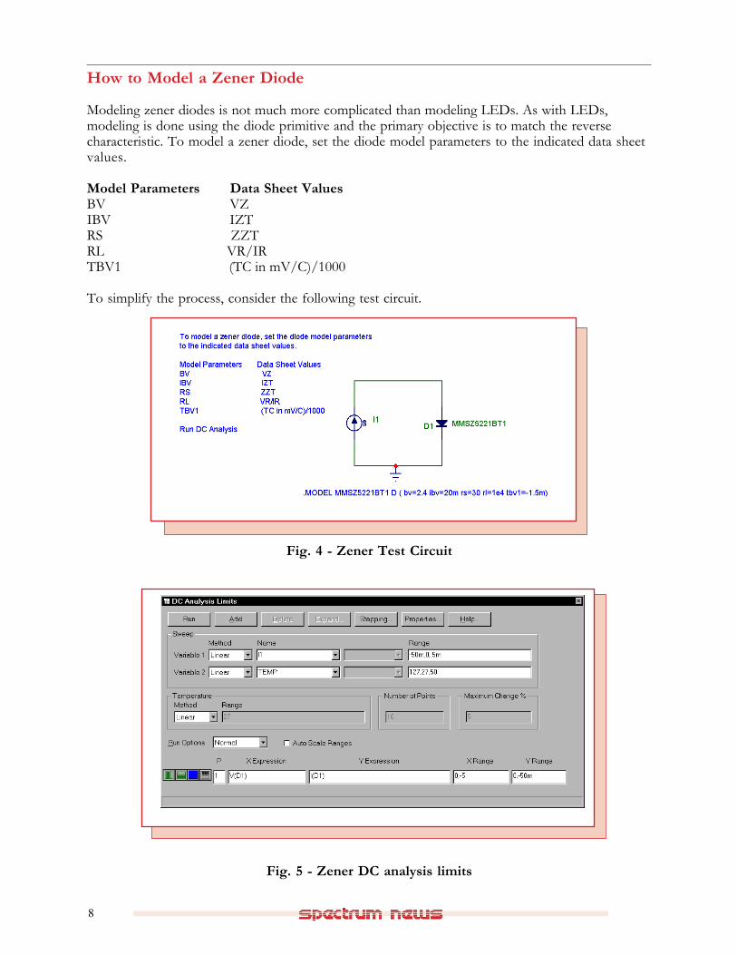
Modeling zener diodes is not much more complicated than modeling LEDs. As with LEDs,modeling is done using the diode primitive and the primary objective is to match the reversecharacteristic. To model a zener diode, set the diode model parameters to the indicated data sheetvalues.
Model Parameters Data Sheet ValuesBV VZIBV IZTRS ZZTRL VR/IRTBV1 (TC in mV/C)/1000
To simplify the process, consider the following test circuit.
Fig. 4 - Zener Test Circuit
Fig. 5 - Zener DC analysis limits

9
Fig. 6 - Zener DC analysis reverse voltage plot
This circuit, when run in DC analysis with the analysis limits of Fig 5, plots the diode's reversecurrent vs. its reverse voltage, stepping the value of temperature from 0 to 127 in steps of 50degrees.
Fig. 6 shows what the DC analysis looks like for the MMSZ5221BT1 zener.
Note that Micro-Cap 6 adjusts the saturation current parameter, IS, to match the BV, IBV point exactly bytaking into account the RS value.
For example, the RS of 30 in this case produces an additional drop when the diode current is at theIBV value of 20ma of 600mv, which, without compensation, would push the BV at 20ma to 2.4 +600mv = 3.0 volts.
You can also add the CJO parameter from the C vs. nominal zener voltage curves, if they are givenin the data sheet. Use the 0 volt bias curves.

10
Two Models for Relays
Occasionally a relay model is needed. Here are two models that work well. The first model, calledRELAY1, is a simple model that includes coil series resistance and inductance, and turn-on andturn-off currents. The other is a more sophisticated but slower running electromechanical model ofthe relay that includes such effects as coil resistance and inductance, turn-on and turnoff delays,nonlinear fringing inductance, plunger rebound and the associated switch bounce.
Here is the RELAY1 model:
Fig. 7 - Relay1 Model
The input circuit of this model includes a user-specified coil resistance and inductance. The coilcurrent is sensed and converted to a voltage by H1 which drives a Schmitt macro to providehysteresis between the ION and IHOLD currents. The output of the Schmitt drives a standardvoltage controlled switch S1.
Figure 8 shows the test circuit used. Figure 9 shows the transient analysis limits.
Fig. 8 - Relay1 test circuit

11
Fig. 10 - Transient analysis of the Relay1 model
Fig. 9 - Transient analysis limits for Relay1 test circuit
The transient analysis in Figure 10 shows the input current waveform and the voltage at the outputswitch. The switch changes closes at the specified current of 15mA and stays closed until the inputcurrent goes below the specified 2.5mA holding current.
The parameters for the RELAY1 model are as follows:
RCOIL Resistance of the relay coilLCOIL Inductance of the relay coilRON Closed resistance of the output switchROFF Open resistance of the output switchION Input current required to close the relay contactsIOFF Input current required to hold the relay contacts closed

12
RELAY2 is a more complicated electromechanical model. It includes a flux circuit and derives amagnetizing force from the flux. It then algebraically sums the magnetizing, stop, friction andrestoring spring forces acting on the plunger to arrive at a net force which is integrated once to getthe plunger velocity and again to get the plunger position. This plunger position directly controlsthe switch contacts.
Here is the RELAY2 model:
Fig. 11 - Relay2 Model
Figure 12 shows the test circuit used. Figure 13 shows the transient analysis limits.
The transient analysis in Figure 14 shows the input current waveform and the voltage at the outputswitch. The display also shows the internal waveforms for the net force, plunger velocity, andplunger position.
The parameters for the macro are shown below. Other constants are defined within the macro andmay be modified to produce different mechanical models.
Fig. 12 - Relay2 test circuit

13
Fig. 14 - Transient analysis of the Relay2 model
Fig. 13 - Transient analysis limits for Relay2 test circuit
ParametersRCOIL Resistance of the relay coilLCOIL Inductance of the relay coilRON Closed resistance of the output switchROFF Open resistance of the output switch
ConstantsAREA Plunger area in square mmM Plunger mass in kilogramsKSPRING Spring constantKFLUX Flux force constantKSTOP Stopping force constantKFORCE Net force scaling constant

14
Product Sheet
Latest Version numbersMicro-Cap 6 ....................................................................... Version 1.3.0Micro-Cap V ...................................................................... Version 2.1.2
Spectrum’s numbersSales .................................................................................... (408) 738-4387Technical Support ............................................................ (408) 738-4389FAX .................................................................................... (408) 738-4702Email sales ......................................................................... [email protected] support .................................................................... [email protected] Site ............................................................................. http://www.spectrum-soft.com
Spectrum's Products• Micro-Cap 6 LAN version (each, with a 2 seat min)$3595.00• Micro-Cap 6 Standard version ..................................... $3595.00• Upgrade from MC5 Ver 2 to MC6 .............................. $500.00• Upgrade from MC5 Ver 1 to MC6 .............................. $750.00
Prices are subject to change. You may order by phone or mail using VISA, MASTERCARD, orAmerican Express. Purchase orders accepted from recognized companies in the U.S. and Canada.California residents please add sales tax.