Embed Size (px)
Citation preview

1

2
3
INTRODUCTION / TABLE OF CONTENTS Step One
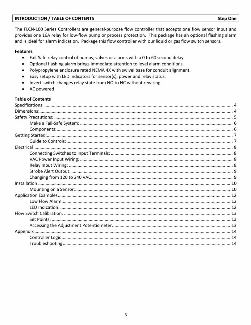
The FLCN‐100 Series Controllers are general‐purpose flow controller that accepts one flow sensor input and provides one 16A relay for low‐flow pump or process protection. This package has an optional flashing alarm and is ideal for alarm indication. Package this flow controller with our liquid or gas flow switch sensors.
Features
Fail‐Safe relay control of pumps, valves or alarms with a 0 to 60 second delay
Optional flashing alarm brings immediate attention to level alarm conditions.
Polypropylene enclosure rated NEMA 4X with swivel base for conduit alignment.
Easy setup with LED indicators for sensor(s), power and relay status.
Invert switch changes relay state from NO to NC without rewiring.
AC powered
Table of Contents Specifications: ......................................................................................................................................................... 4 Dimensions:............................................................................................................................................................. 4 Safety Precautions: ................................................................................................................................................. 5
Make a Fail‐Safe System: ............................................................................................................................ 6 Components: ............................................................................................................................................... 6
Getting Started: ....................................................................................................................................................... 7 Guide to Controls: ....................................................................................................................................... 7 Electrical .................................................................................................................................................................. 8 Connecting Switches to Input Terminals: ................................................................................................... 8 VAC Power Input Wiring: ............................................................................................................................ 8 Relay Input Wiring: ..................................................................................................................................... 8 Strobe Alert Output: ................................................................................................................................... 9 Changing from 120 to 240 VAC ................................................................................................................... 9 Installation ............................................................................................................................................................ 10 Mounting on a Sensor: .............................................................................................................................. 10 Application Examples ............................................................................................................................................ 12 Low Flow Alarm:........................................................................................................................................ 12 LED Indication: .......................................................................................................................................... 12 Flow Switch Calibration: ....................................................................................................................................... 13 Set Points: ................................................................................................................................................. 13 Accessing the Adjustment Potentiometer: ............................................................................................... 13 Appendix ............................................................................................................................................................... 14 Controller Logic ......................................................................................................................................... 14 Troubleshooting ........................................................................................................................................ 14
4
SPECIFICATIONS/DIMENSIONS Step Two
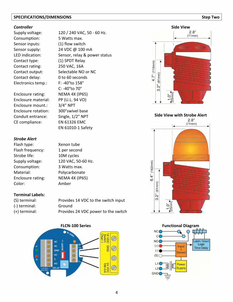
Controller Supply voltage: 120 / 240 VAC, 50 ‐ 60 Hz. Consumption: 5 Watts max. Sensor inputs: (1) flow switch Sensor supply: 24 VDC @ 100 mA LED indication: Sensor, relay & power status Contact type: (1) SPDT Relay Contact rating: 250 VAC, 16A Contact output: Selectable NO or NC Contact delay: 0 to 60 seconds Electronics temp.: F: ‐40°to 158° C: ‐40°to 70° Enclosure rating: NEMA 4X (IP65) Enclosure material: PP (U.L. 94 VO) Enclosure mount.: 3/4” NPT Enclosure rotation: 300°swivel base Conduit entrance: Single, 1/2" NPT CE compliance: EN 61326 EMC EN 61010‐1 Safety Strobe Alert Flash type: Xenon tube Flash frequency: 1 per second Strobe life: 10M cycles Supply voltage: 120 VAC, 50‐60 Hz. Consumption: 3 Watts max. Material: Polycarbonate Enclosure rating: NEMA 4X (IP65) Color: Amber Terminal Labels: (S) terminal: Provides 14 VDC to the switch input (‐) terminal: Ground (+) terminal: Provides 24 VDC power to the switch
Side View
Side View with Strobe Alert
FLCN‐100 Series Functional Diagram
5
SAFETY PRECAUTIONS Step Three
About This Manual: PLEASE READ THE ENTIRE MANUAL PRIOR TO INSTALLING OR USING THIS PRODUCT.
This manual includes information on two different models of Compact Relay Flow Controllers from Omega
Engineering: FLCN‐101, FLCN‐111 and FLCN‐111‐CE. The FLCN‐100 Series is a single‐input controller with
an optional Flash Alarm™. Many aspects of installation and use are similar between the three models.
User’s Responsibility for Safety: OMEGA ENGINEERING manufactures several models of controller, with
different mounting and switching configurations. It is the user’s responsibility to select a controller model
that is appropriate for the application, install it properly, perform tests of the installed system, and
maintain all components.
Electrical Shock Hazard: It is possible to contact components on the controller that carry high voltage,
causing serious injury or death. All power to the controller and the relay circuit(s) it controls should be
turned OFF prior to working on the controller. If it is necessary to make adjustments during powered
operation, use extreme caution and use only insulated tools. Making adjustments to powered controllers
is not recommended. Wiring should be performed by qualified personnel in accordance with all applicable
national, state and local electrical codes.
Flammable or Explosive Applications: Sensor mount controllers should not be used with explosive or
flammable liquids, which require an intrinsically safe or explosion proof rating. If you are unsure of the
suitability of a controller for your installation, consult your Omega Engineering representative for further
information.
Install In a Dry Location: The FLCN‐100 Series controller housing is liquid‐resistant and made of
Polypropylene (PP). When installed properly, the controller is not designed to be immersed. It should be
mounted in such a way that it does not normally come into contact with fluid. Refer to an industry
reference to ensure that compounds that may splash onto the controller housing will not damage it. Such
damage is not covered by the warranty.
Relay Contact Rating: The relay is rated for a 16 amp resistive load. Many loads (such as a motor during
start‐up or incandescent lights) are reactive and may have an inrush current characteristic that may be 10
to 20 times their steady‐state load rating. The use of a contact protection circuit may be necessary for
your installation if the 16 amp rating does not provide an ample margin for such inrush currents.
6
SAFETY PRECAUTIONS (cont.) Step Three
Make a Fail‐Safe System: Design a fail‐safe system that accommodates the possibility of relay or power failure. If power is cut off to the controller, it will de‐energize the relay. Make sure that the de‐energized state of the relay is the safe state in your process. For example, if controller power is lost, a pump filling a tank will turn off if it is connected to the Normally Open side of the relay.
While the internal relay is reliable, over the course of time relay failure is possible in two modes: under a heavy load the contacts may be “welded” or stuck into the energized position, or corrosion may buildup on a contact so that it will not complete the circuit when it should. In critical applications, redundant backup systems and alarms must be used in addition to the primary system. Such backup systems should use different sensor technologies where possible.
While this manual offers some examples and suggestions to help explain the operation of OMEGA ENGINEERING products, such examples are for information only and are not intended as a complete guide to installing any specific system.
Sensor‐mount controllers: The FLCN‐100 Series is a cost‐effective, modular flow controller, whose body incorporates a female 3/4" NPT fitting, allowing it to be mounted directly onto any Omega Engineering sensor or any 3/4" connection. Simply provide its required AC power and a controlled device such as a valve, pump, or alarm that can be switched by the controller’s relay in response to the sensor input.
Features of the FLCN‐100 Series Single Input Controller: The FLCN‐100 Series Controller is designed to receive a signal from a single flow switch. It turns its internal relay On or Off (as set by the invert switch) in response to the presence of flow or no‐flow, and changes the relay status back again when the sensor reverses. The FLCN‐100 Series may be used with any Omega Engineering relay flow switch (FST‐200 & FST‐300 series). The relay is a single pole, double throw type; the controlled device can be connected to either the normally open or normally closed side of the relay. A time delay from 0 to 60 seconds can be set before the relay responds to the sensor input.
Typical applications for the FLCN‐100 Series are flow or no‐flow switch/alarm operations (activating an alarm at no‐flow).
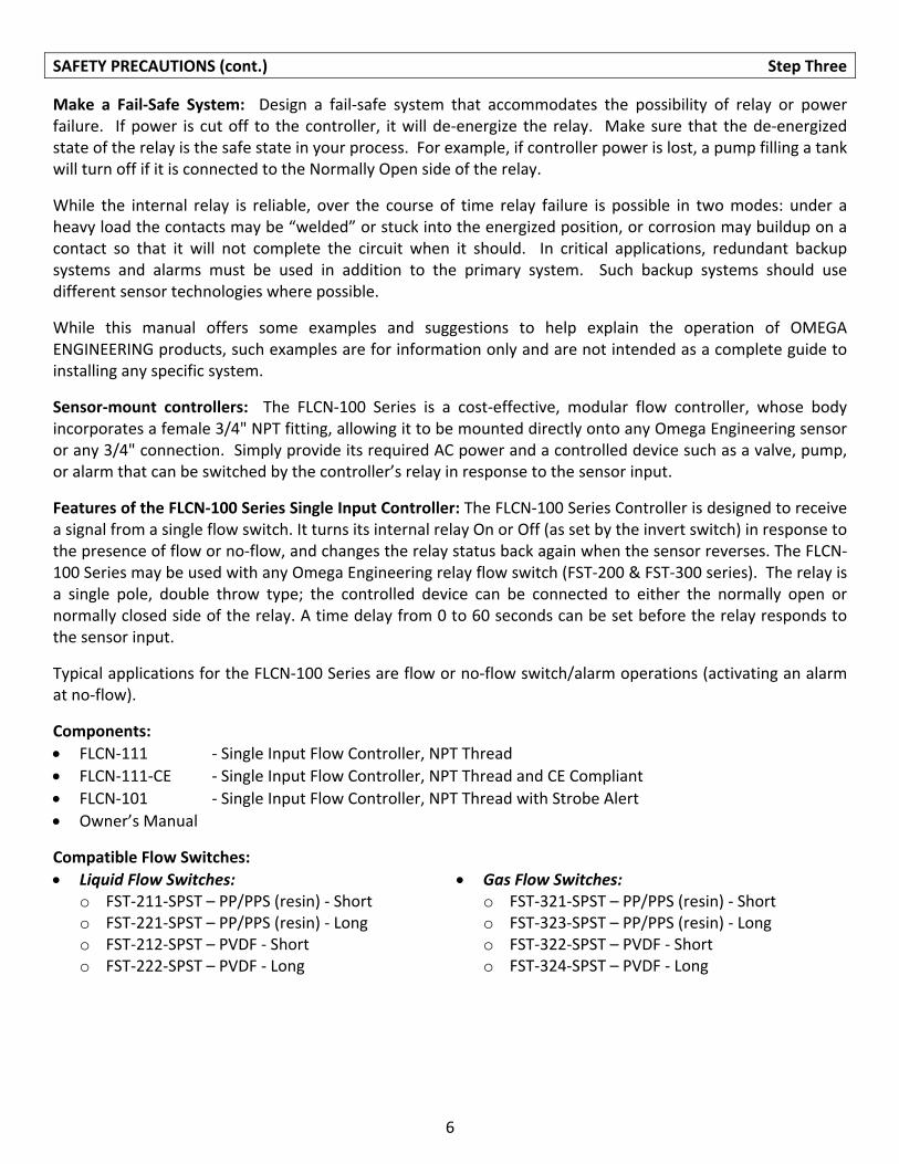
Components:
FLCN‐111 ‐ Single Input Flow Controller, NPT Thread
FLCN‐111‐CE ‐ Single Input Flow Controller, NPT Thread and CE Compliant
FLCN‐101 ‐ Single Input Flow Controller, NPT Thread with Strobe Alert
Owner’s Manual
Compatible Flow Switches:
Liquid Flow Switches: o FST‐211‐SPST – PP/PPS (resin) ‐ Short o FST‐221‐SPST – PP/PPS (resin) ‐ Long o FST‐212‐SPST – PVDF ‐ Short o FST‐222‐SPST – PVDF ‐ Long
Gas Flow Switches: o FST‐321‐SPST – PP/PPS (resin) ‐ Short o FST‐323‐SPST – PP/PPS (resin) ‐ Long o FST‐322‐SPST – PVDF ‐ Short o FST‐324‐SPST – PVDF ‐ Long
7
GETTING STARTED Step Four
The FLCN‐100 Series may be used with any Omega Engineering flow switch (FST‐200 & FST‐300 series) with a relay output. The relay is a single pole, double throw type; the controlled device can be connected to either the normally open or normally closed side of the relay. A time delay from 0 to 60 seconds can be set before the relay responds to the sensor input. Typical applications for the FLCN‐100 Series are pump protection, no‐flow indication or chemical injection.
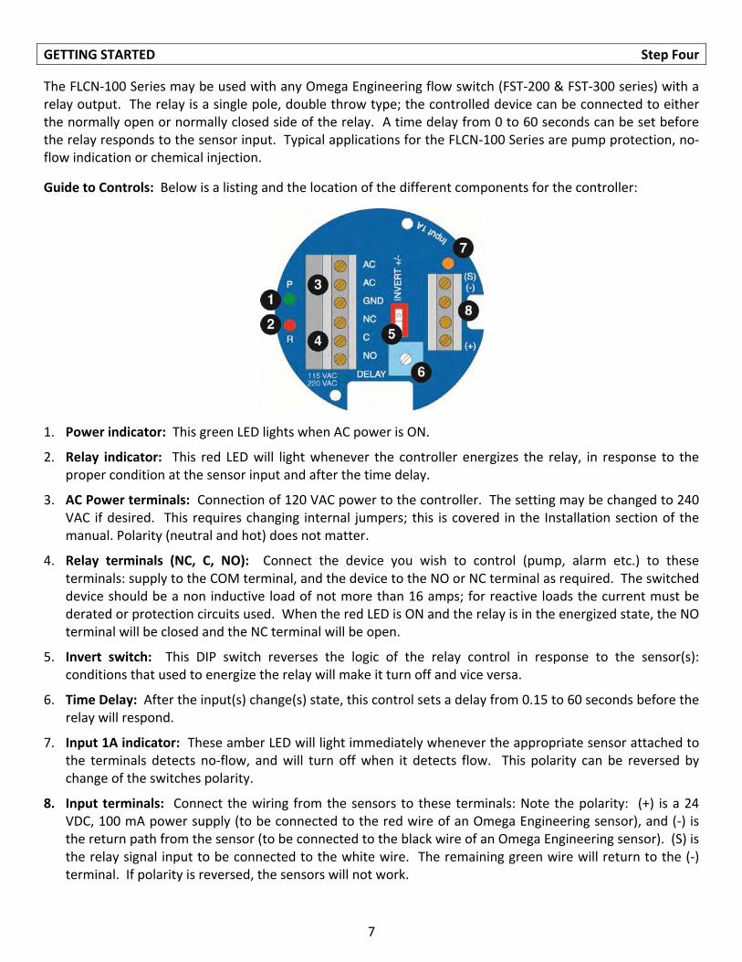
Guide to Controls: Below is a listing and the location of the different components for the controller:
1. Power indicator: This green LED lights when AC power is ON.
2. Relay indicator: This red LED will light whenever the controller energizes the relay, in response to the proper condition at the sensor input and after the time delay.
3. AC Power terminals: Connection of 120 VAC power to the controller. The setting may be changed to 240 VAC if desired. This requires changing internal jumpers; this is covered in the Installation section of the manual. Polarity (neutral and hot) does not matter.
4. Relay terminals (NC, C, NO): Connect the device you wish to control (pump, alarm etc.) to these terminals: supply to the COM terminal, and the device to the NO or NC terminal as required. The switched device should be a non inductive load of not more than 16 amps; for reactive loads the current must be derated or protection circuits used. When the red LED is ON and the relay is in the energized state, the NO terminal will be closed and the NC terminal will be open.
5. Invert switch: This DIP switch reverses the logic of the relay control in response to the sensor(s): conditions that used to energize the relay will make it turn off and vice versa.
6. Time Delay: After the input(s) change(s) state, this control sets a delay from 0.15 to 60 seconds before the relay will respond.
7. Input 1A indicator: These amber LED will light immediately whenever the appropriate sensor attached to the terminals detects no‐flow, and will turn off when it detects flow. This polarity can be reversed by change of the switches polarity.
8. Input terminals: Connect the wiring from the sensors to these terminals: Note the polarity: (+) is a 24 VDC, 100 mA power supply (to be connected to the red wire of an Omega Engineering sensor), and (‐) is the return path from the sensor (to be connected to the black wire of an Omega Engineering sensor). (S) is the relay signal input to be connected to the white wire. The remaining green wire will return to the (‐) terminal. If polarity is reversed, the sensors will not work.
8
ELECTRICAL Step Five
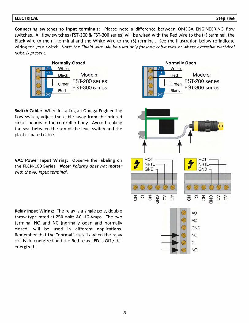
Connecting switches to input terminals: Please note a difference between OMEGA ENGINEERING flow switches. All flow switches (FST‐200 & FST‐300 series) will be wired with the Red wire to the (+) terminal, the Black wire to the (‐) terminal and the White wire to the (S) terminal. See the illustration below to indicate wiring for your switch. Note: the Shield wire will be used only for long cable runs or where excessive electrical noise is present.
Normally Closed Normally Open
Switch Cable: When installing an Omega Engineering flow switch, adjust the cable away from the printed circuit boards in the controller body. Avoid breaking the seal between the top of the level switch and the plastic coated cable.
VAC Power Input Wiring: Observe the labeling on the FLCN‐100 Series. Note: Polarity does not matter with the AC input terminal.
Relay Input Wiring: The relay is a single pole, double throw type rated at 250 Volts AC, 16 Amps. The two terminal NO and NC (normally open and normally closed) will be used in different applications. Remember that the "normal" state is when the relay coil is de‐energized and the Red relay LED is Off / de‐energized.
9
ELECTRICAL (continued) Step Five
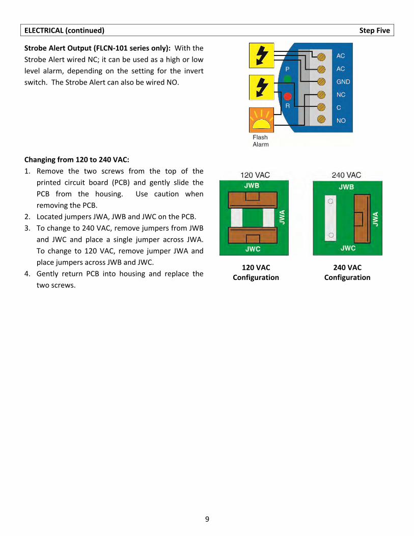
Strobe Alert Output (FLCN‐101 series only): With the
Strobe Alert wired NC; it can be used as a high or low
level alarm, depending on the setting for the invert
switch. The Strobe Alert can also be wired NO.
Changing from 120 to 240 VAC:
1. Remove the two screws from the top of the
printed circuit board (PCB) and gently slide the
PCB from the housing. Use caution when
removing the PCB.
2. Located jumpers JWA, JWB and JWC on the PCB.
3. To change to 240 VAC, remove jumpers from JWB
and JWC and place a single jumper across JWA.
To change to 120 VAC, remove jumper JWA and
place jumpers across JWB and JWC.
4. Gently return PCB into housing and replace the
two screws.
120 VAC 240 VAC Configuration Configuration
10
INSTALLATION Step Six
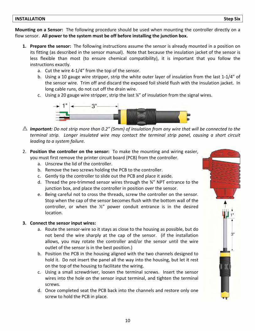
Mounting on a Sensor: The following procedure should be used when mounting the controller directly on a flow sensor. All power to the system must be off before installing the junction box.
1. Prepare the sensor: The following instructions assume the sensor is already mounted in a position on its fitting (as described in the sensor manual). Note that because the insulation jacket of the sensor is less flexible than most (to ensure chemical compatibility), it is important that you follow the instructions exactly.
a. Cut the wire 4‐1/4” from the top of the sensor. b. Using a 10 gauge wire stripper, strip the white outer layer of insulation from the last 1‐1/4” of
the sensor wire. Trim off and discard the exposed foil shield flush with the insulation jacket. In long cable runs, do not cut off the drain wire.
c. Using a 20 gauge wire stripper, strip the last ¼” of insulation from the signal wires.
Important: Do not strip more than 0.2” (5mm) of insulation from any wire that will be connected to the terminal strip. Longer insulated wire may contact the terminal strip panel, causing a short circuit leading to a system failure.
2. Position the controller on the sensor: To make the mounting and wiring easier, you must first remove the printer circuit board (PCB) from the controller.
a. Unscrew the lid of the controller. b. Remove the two screws holding the PCB to the controller. c. Gently tip the controller to slide out the PCB and place it aside. d. Thread the pre‐trimmed sensor wires through the ¾” NPT entrance to the
junction box, and place the controller in position over the sensor. e. Being careful not to cross the threads, screw the controller on the sensor.
Stop when the cap of the sensor becomes flush with the bottom wall of the controller, or when the ½” power conduit entrance is in the desired location.
3. Connect the sensor input wires: a. Route the sensor‐wire so it stays as close to the housing as possible, but do
not bend the wire sharply at the cap of the sensor. (if the installation allows, you may rotate the controller and/or the sensor until the wire outlet of the sensor is in the best position.)
b. Position the PCB in the housing aligned with the two channels designed to hold it. Do not insert the panel all the way into the housing, but let it rest on the top of the housing to facilitate the wiring.
c. Using a small screwdriver, loosen the terminal screws. Insert the sensor wires into the hole on the sensor input terminal, and tighten the terminal screws.
d. Once completed seat the PCB back into the channels and restore only one screw to hold the PCB in place.
11
INSTALLATION (continued) Step Six
4. Mechanical connection to conduit: All wiring between a controller and sensors should be in conduit. The power entrance of the controller is a standard ½” NPT female fitting that will attach to standard electrical conduit, either plastic or metal, as specified by local codes. Keep in mind that the housing may have to be unscrewed from the sensor for periodic cleaning of the sensor. For this reason the use of flexible conduit, providing enough slack for easy access is recommended.
5. Connect the extension wiring: Before making connections, make sure all power to the system (controller, motor, valve, alarm, etc.) is OFF with a safety lockout on the circuit breaker.
a. The extension wiring to controller should take into account long cable runs. If the run is long, it may need to be a slightly thicker gauge so the series resistance is kelp within allowable limits.
b. Thread the extension wiring through the power conduit entrance of the housing. c. Strip ¼” of the insulation from the ends of the wires. d. Loosen the appropriate terminal screws. Insert the extension wires into the corresponding
terminals, matching the sensor wires. e. Tighten the terminal screws. f. Return the wire protector to its location and restore the final screw which holds the wire
protected and PCB in its place. g. Replace the cap.
Note: In some cases, additional user‐provided components may need to be attached to the terminals. If
so, make sure that both wires and/or components entering the terminal are secure after the screws are
tightened.
Note: Always tighten the controller from the wrench flat located on the swivel base. Never tighten from the body of the controller.
12
APPLICATION EXAMPLES Step Seven
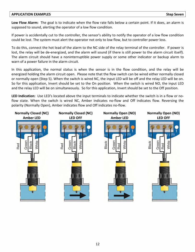
Low Flow Alarm: The goal is to indicate when the flow rate falls below a certain point. If it does, an alarm is supposed to sound, alerting the operator of a low flow condition.
If power is accidentally cut to the controller, the sensor's ability to notify the operator of a low flow condition could be lost. The system must alert the operator not only to low flow, but to controller power loss.
To do this, connect the hot lead of the alarm to the NC side of the relay terminal of the controller. If power is lost, the relay will be de‐energized, and the alarm will sound (if there is still power to the alarm circuit itself). The alarm circuit should have a noninterruptible power supply or some other indicator or backup alarm to warn of a power failure in the alarm circuit.
In this application, the normal status is when the sensor is in the flow condition, and the relay will be energized holding the alarm circuit open. Please note that the flow switch can be wired either normally closed or normally open (Step 5). When the switch is wired NC, the input LED will be off and the relay LED will be on. So for this application, Invert should be set to the On position. When the switch is wired NO, the input LED and the relay LED will be on simultaneously. So for this application, Invert should be set to the Off position.
LED Indication: Use LED's located above the input terminals to indicate whether the switch is in a flow or no‐flow state. When the switch is wired NC, Amber indicates no‐flow and Off indicates flow. Reversing the polarity (Normally Open), Amber indicates flow and Off indicates no‐flow.
Normally Closed (NC) Amber LED
Normally Closed (NC) LED OFF
Normally Open (NO) Amber LED
Normally Open (NO) LED OFF
13
FLOW SWITCH CALIBRATION Step Eight
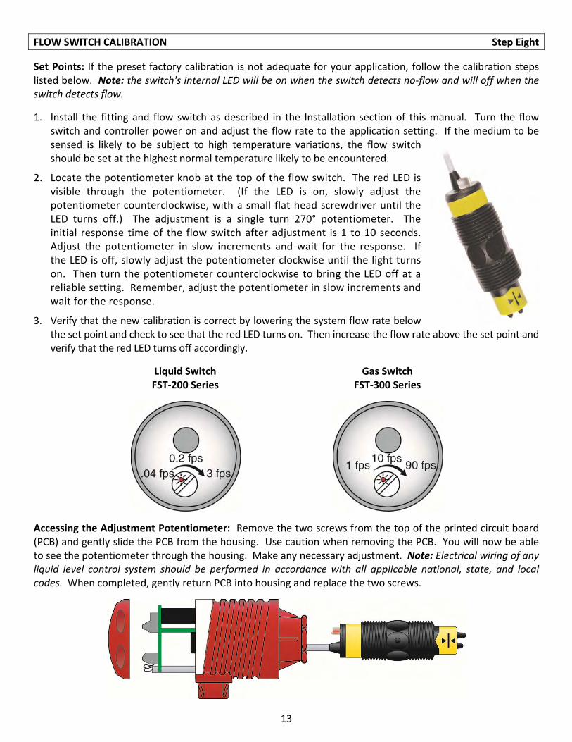
Set Points: If the preset factory calibration is not adequate for your application, follow the calibration steps listed below. Note: the switch's internal LED will be on when the switch detects no‐flow and will off when the switch detects flow.
1. Install the fitting and flow switch as described in the Installation section of this manual. Turn the flow switch and controller power on and adjust the flow rate to the application setting. If the medium to be sensed is likely to be subject to high temperature variations, the flow switch should be set at the highest normal temperature likely to be encountered.
2. Locate the potentiometer knob at the top of the flow switch. The red LED is visible through the potentiometer. (If the LED is on, slowly adjust the potentiometer counterclockwise, with a small flat head screwdriver until the LED turns off.) The adjustment is a single turn 270° potentiometer. The initial response time of the flow switch after adjustment is 1 to 10 seconds. Adjust the potentiometer in slow increments and wait for the response. If the LED is off, slowly adjust the potentiometer clockwise until the light turns on. Then turn the potentiometer counterclockwise to bring the LED off at a reliable setting. Remember, adjust the potentiometer in slow increments and wait for the response.
3. Verify that the new calibration is correct by lowering the system flow rate below the set point and check to see that the red LED turns on. Then increase the flow rate above the set point and verify that the red LED turns off accordingly.
Liquid Switch FST‐200 Series
Gas Switch FST‐300 Series
Accessing the Adjustment Potentiometer: Remove the two screws from the top of the printed circuit board (PCB) and gently slide the PCB from the housing. Use caution when removing the PCB. You will now be able to see the potentiometer through the housing. Make any necessary adjustment. Note: Electrical wiring of any liquid level control system should be performed in accordance with all applicable national, state, and local codes. When completed, gently return PCB into housing and replace the two screws.
14
APPENDIX Step Nine
Controller Logic: Please use the following guide to understand the operation of the controllers.
1. Power LED: Make sure the Green power LED is ON when power is supplied to the controller.
2. Input LED: For NC switch wiring, the input LED on the controller will be Amber when the switch reads no‐flow and OFF when the switch reads flow.
3. Invert Operation: When the input LED turn Off and On, the relay LED will also switch. With invert Off, the relay LED will be On when the input LED is On and Off when the input LED is Off. With invert On, the relay LED will be Off when the input LED is On and On when the input LED is Off.
4. Relay Operation: The relay may be wired either NO or NC. The normal state of the relay is when its LED is Off. With the LED On, the relay is in the energized mode and all terminal connections are reversed.
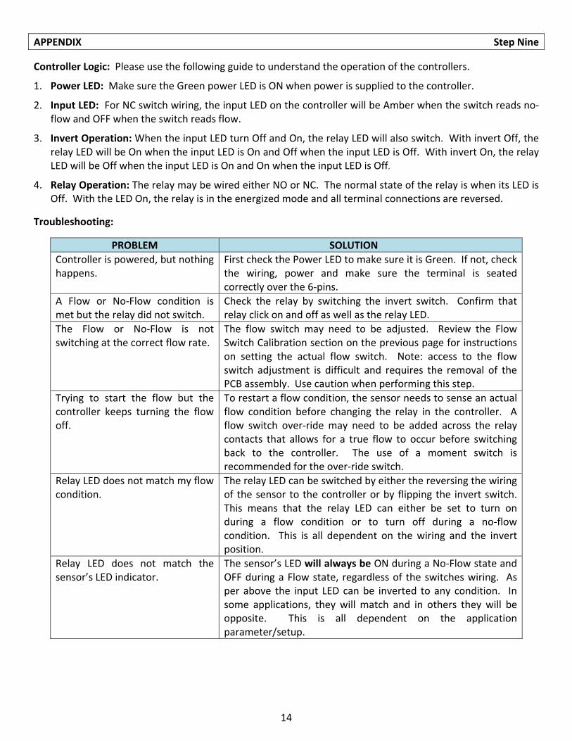
Troubleshooting:
PROBLEM SOLUTION
Controller is powered, but nothing happens.
First check the Power LED to make sure it is Green. If not, check the wiring, power and make sure the terminal is seated correctly over the 6‐pins.
A Flow or No‐Flow condition is met but the relay did not switch.
Check the relay by switching the invert switch. Confirm that relay click on and off as well as the relay LED.
The Flow or No‐Flow is not switching at the correct flow rate.
The flow switch may need to be adjusted. Review the Flow Switch Calibration section on the previous page for instructions on setting the actual flow switch. Note: access to the flow switch adjustment is difficult and requires the removal of the PCB assembly. Use caution when performing this step.
Trying to start the flow but the controller keeps turning the flow off.
To restart a flow condition, the sensor needs to sense an actual flow condition before changing the relay in the controller. A flow switch over‐ride may need to be added across the relay contacts that allows for a true flow to occur before switching back to the controller. The use of a moment switch is recommended for the over‐ride switch.
Relay LED does not match my flow condition.
The relay LED can be switched by either the reversing the wiring of the sensor to the controller or by flipping the invert switch. This means that the relay LED can either be set to turn on during a flow condition or to turn off during a no‐flow condition. This is all dependent on the wiring and the invert position.
Relay LED does not match the sensor’s LED indicator.
The sensor’s LED will always be ON during a No‐Flow state and OFF during a Flow state, regardless of the switches wiring. As per above the input LED can be inverted to any condition. In some applications, they will match and in others they will be opposite. This is all dependent on the application parameter/setup.

15

16