Embed Size (px)
Citation preview

M. ChidambaramIndian Institute of Technology, Chennai
Vivek SatheDr. Babasaheb Ambedkar Technological University, Maharashtra
Relay Autotuning for Identification and Control
Cambridge University Press978-1-107-05871-2 - Relay Autotuning for Identification and ControlM. Chidambaram and Vivek SatheFrontmatterMore information
www.cambridge.org© in this web service Cambridge University Press

Cambridge House, 4381/4 Ansari Road, Daryaganj, Delhi 110002, India
Cambridge University Press is part of the University of Cambridge.
It furthers the University’s mission by disseminating knowledge in the pursuit ofeducation, learning and research at the highest international levels of excellence.
www.cambridge.orgInformation on this title: www.cambridge.org/9781107058712
© M. Chidambaram and Vivek Sathe 2014
This publication is in copyright. Subject to statutory exceptionand to the provisions of relevant collective licensing agreements,no reproduction of any part may take place without the writtenpermission of Cambridge University Press.
First published 2014
Printed in India
A catalogue record for this publication is available from the British Library
Library of Congress Cataloging-in-Publication DataChidambaram, M.Relay autotuning for identification and control / M. Chidambaram, Vivek Sathe. pages cmSummary: “Provides a simple method of designing P/PI controllers for series and parallel cascade control schemes for effective industrial operations”–Provided by publisher.Includes bibliographical references and index.ISBN 978-1-107-05871-2 (hardback)1. Relay control systems. 2. Self-tuning controllers. 3. Electric relays–Automatic control. I. Sathe, Vivek. II. Title. TJ217.C4765 2014629.8’36–dc23
ISBN 978-1-107-05871-2 Hardback
Cambridge University Press has no responsibility for the persistence or accuracy of URLs for external or third-party internet websites referred to in this publication,and does not guarantee that any content on such websites is, or will remain,accurate or appropriate.
Cambridge University Press978-1-107-05871-2 - Relay Autotuning for Identification and ControlM. Chidambaram and Vivek SatheFrontmatterMore information
www.cambridge.org© in this web service Cambridge University Press

List of Figures ixList of Tables xviiAcknowledgements xxiPreface xxiii
1. Introduction 1.1 Relay Feedback Method 1 1.2 Identification by Symmetric Relay Feedback Method 3 1.3 Identification using Asymmetrical Relay 4 1.4 Identification of Unstable Processes 5 1.5 Autotuning of Cascade Control System 6 1.6 Relay Tuning of Multivariable System 7 1.7 PI/PID Controller Design 8
2. Improved Autotune Identification Methods 2.1 Introduction 12 2.2 Estimation of Time Delay 13 2.3 Method for Considering Higher Order Harmonics 15 2.4 Simulation Study 20 2.5 Modified Asymmetrical Relay Method for Improved System Identification 22 2.6 Method 23 2.7 Simulation Results 25 2.8 Conclusions 29
3. Cascade Controllers Tuning by Relay Autotune Method 3.1 Introduction 30 3.2 Method 1 31 3.3 Method 2 35 3.4 Parallel Cascade Controllers 38
Contents
Cambridge University Press978-1-107-05871-2 - Relay Autotuning for Identification and ControlM. Chidambaram and Vivek SatheFrontmatterMore information
www.cambridge.org© in this web service Cambridge University Press

iv Contents
3.5 Method 1 for Parallel Cascade Control Systems 383.6 Method 2 for Parallel Cascade Control Systems 413.7 Conclusions 42
4. Simultaneous Relay Autotuning of Cascade Controllers4.1 Introduction 434.2 Method for Series Cascade Control Systems 444.3 Method for Parallel Cascade Control Systems 494.4 Simulation Study 504.5 Higher Order Harmonics in both the Loops 524.6 Conclusions 56
5. A Simple Method of Tuning Cascade Controllers5.1 Introduction 575.2 Method for Series Cascade Control Systems 585.3 Simulation Results 605.4 Stability Analysis 705.5 Method for Parallel Cascade Control Systems 715.6 Simulation Results for Parallel Cascade Controllers 735.7 Conclusions 78
6. Improved Saturation Relay Test for Systems with Large Dead Time6.1 Introduction 796.2 Importance of Saturation Relay Slope 806.3 Method 1 806.4 Method 2 826.5 Simulation Study 83
6.5.1 Case study 1 83 6.5.2 Effect of noise 85 6.5.3 Case study 2 86 6.5.4 Case studies 3 and 4 87
6.6 Non-Relay Identification Methods 896.7 Conclusions 91
7. Identification of FOPTD Model using Single Symmetrical Relay Test7.1 Introduction 937.2 Problem Description 947.3 Relay Test 94
Cambridge University Press978-1-107-05871-2 - Relay Autotuning for Identification and ControlM. Chidambaram and Vivek SatheFrontmatterMore information
www.cambridge.org© in this web service Cambridge University Press

Contents v
7.4 Estimation of kp, D and t 947.5 Simulation Study 97
7.5.1 Case study 1 97 7.5.2 Case study 2 99 7.5.3 Case study 3 100 7.5.4 Case study 4 101
7.6 Conclusions 104
8. Autotuning of PID Controllers for Unstable FOPTD Systems8.1 Introduction 1058.2 Problem Description 1078.3 Consideration of Higher Order Harmonics 1078.4 Estimation of kp, D and t 1108.5 Simulation Study 111
8.5.1 Case study 1 111 8.5.2 Case study 2 113 8.5.3 Effect of measurement noise on identification 115 8.5.4 Effect of load on model parameter identification 116
8.6 Simulation Study of an Unstable Non-linear Bioreactor 1178.7 Conclusions 119
9. Autotuning of PID Controllers for Critically Damped SOPTD Systems9.1 Introduction 1209.2 Problem Description 1219.3 Consideration of Higher Order Harmonics 1229.4 Estimation of kp, D and t using ku 1279.5 Simulation Study 128
9.5.1 Case study 1 128 9.5.2 Case study 2 131 9.5.3 Case study 3 133 9.5.4 Effect of measurement noise on identification 135 9.5.5 Effect of load on model parameter identification 135
9.6 Simulation Study of a Non-linear Bioreactor System 1369.7 Estimation of kp, D and t without using ku 1399.8 Simulation Study 1409.9 Conclusions 142
10. Estimation of SOPTD Transfer Function Model10.1 Introduction 143
Cambridge University Press978-1-107-05871-2 - Relay Autotuning for Identification and ControlM. Chidambaram and Vivek SatheFrontmatterMore information
www.cambridge.org© in this web service Cambridge University Press

vi Contents
10.2 Problem Description 14410.3 Relay Test 14410.4 Estimation of Process Gain 14510.5 Estimation of q, t1 and t2 14510.6 Simulation Results 147
10.6.1 Case study 1 147 10.6.2 Case study 2 148 10.6.3 Case study 3 149 10.6.4 Case study 4 149
10.7 Conclusions 150
11. Estimation of Five Parameters of Unstable SOPTD Model with a Zero 11.1 Introduction 15111.2 Problem Description 15311.3 Relay Test 15311.4 Parameter Estimation 15311.5 Simulation Results 156
11.5.1 Case study 1 156 11.5.2 Case study 2 159
11.5.3 Case study 3 16011.6 Simulation Application to a Non-linear Continuous Stirred
Tank Reactor (CSTR) 16211.7 Conclusions 164
12. Identification of FOPTD Multivariable Systems 12.1 Introduction 16512.2 Relay Identification 16612.3 Estimation of Model Parameters (t and q) 16812.4 Comparision of Closed Loop Performance 16812.5 Examples 169
12.5.1 Example 1 169 12.5.2 Example 2 170
12.6 Conclusions 173
13. Identification of SOPTD Multivariable Systems13.1 Introduction 17413.2 Relay Identification 17513.3 Estimation of Model Parameters 17613.4 Comparison of Closed Loop Performance 177
Cambridge University Press978-1-107-05871-2 - Relay Autotuning for Identification and ControlM. Chidambaram and Vivek SatheFrontmatterMore information
www.cambridge.org© in this web service Cambridge University Press

Contents vii
13.5 Simulation Examples 17713.6 Conclusions 180
14. Tuning of Multivariable Controllers for Non-Minimum Phase Systems14.1 Introduction 18314.2 Controller Design Methods 184
14.2.1 Simple tuning method 184 14.2.2 Decoupled internal model controller method 185
14.3 Comparison Criterion of Controllers Performance 18714.4 Examples 187
14.4.1 Example 1 187 14.4.2 Example 2 191 14.4.3 Example 3 192
14.5 Conclusions 193
15. Tuning of Multivariable Controllers by Genetic Algorithms15.1 Introduction 19515.2 Genetic Algorithms 19615.3 Objective Function 19615.4 Design Example 19715.5 Decentralized Controllers 19815.6 Centralized Controllers 20215.7 Example 2: Niederlinski Model 20315.8 Conclusions 205
16. Summary and Conclusions16.1 Improved Autotune Identification Method 20616.2 Series Cascade Controller Tuning 206
16.2.1 Symmetric relay method 207 16.2.2 Asymmetric relay method 207 16.2.3 Simultaneous relay autotuning of cascade controllers 208
16.3 A Simple Method of Designing Cascade Controllers 20916.4 Improved Saturation Relay Test for Systems with Large Dead Time 20916.5 Model Parameters using Single Symmetrical Relay Test 210
16.5.1 FOPTD systems 210 16.5.2 Autotuning of unstable FOPTD system 210 16.5.3 Autotuning of PID controllers for critically damped stable SOPTD
system 210
Cambridge University Press978-1-107-05871-2 - Relay Autotuning for Identification and ControlM. Chidambaram and Vivek SatheFrontmatterMore information
www.cambridge.org© in this web service Cambridge University Press

viii Contents
16.6 Estimation of Model Parameters of SOPTD System 21116.7 Identification of Five Parameters of Unstable SOPTD System 21116.8 Identification of FOPTD Multivariable Systems 21216.9 Identification of SOPTD Multivariable Systems 21216.10 Comparison of Multivariable Controllers Tuning Methods 21216.11 Tuning of Multivariable Controllers by Genetic Algorithm 21316.12 Conclusions 213
Appendix A 215Appendix B 220Appendix C 230Nomenclature 239Problems 243Suggestive Reading 247References 249Index 259
Cambridge University Press978-1-107-05871-2 - Relay Autotuning for Identification and ControlM. Chidambaram and Vivek SatheFrontmatterMore information
www.cambridge.org© in this web service Cambridge University Press

List of Figures
1.1 Block diagram for symmetric relay feedback system 21.2 Response of a relay feedback system 21.3 Block diagram for asymmetric relay feedback system 51.4 Block diagram for saturation relay feedback system 51.5 Series cascade control scheme 61.6 Relay feedback tuning of cascade control system 72.1 Relay feedback oscillations for the system exp(–2s)/[(10s + 1)(s + 1)] relay height = 1 142.2 The open loop comparisons of the original system and the identified model 152.3 Relay feedback oscillations for the system (a) exp(–4s)/(s+1); (b) exp(–4s)/(0.4s+1) relay
height = 1 182.4 Relay feedback oscillations for the system exp(–4s)/(0.5s+1)3 relay height = 1 212.5 Open loop comparisons of actual system and the identified FOPTD models
21 2.6 The closed loop response of the system exp(–4s)/(0.5s+1)3 (controller design by the
closed Ziegler–Nichols method) 222.7 The closed loop performance of the system exp(–4s)/(0.5s+1)3 (controller design by the
open Ziegler–Nichols method) 222.8 Block diagram for asymmetric relay feedback system 232.9 Closed loop response comparisons for case study 1 252.10 Closed loop response comparisons for case study 2 262.11 Closed loop response comparisons for case study 3 272.12 Closed loop servo response of the unstable FOPTD system 283.1 Relay feedback tuning of cascade control system 303.2 Response in y2 using symmetric relay (with relay height ±1) in inner loop 313.3 Response in y1 for symmetric relay in outer loop (with inner loop on PI settings) 32
Cambridge University Press978-1-107-05871-2 - Relay Autotuning for Identification and ControlM. Chidambaram and Vivek SatheFrontmatterMore information
www.cambridge.org© in this web service Cambridge University Press

x List of Figures
3.4a Servo response in y1 using PID controller for outer loop and PI for inner loop for the first example 33
3.4b Response in u corresponding to Fig. 3.4a. PID controller for outer loop and PI for inner loop (for first example) 33
3.5 Regulatory response in y1 for a disturbance in inner loop. PID controller for outer loop and PI for inner loop (first example) 34
3.6a Servo response in y1 using PID controller for outer loop and PI for inner loop for the second example 36
3.6b Response in u corresponding to Fig. 3.6a. PID controller for outer loop and PI for inner loop (second example) 37
3.6c Regulatory response in y1 for a disturbance in inner loop. PID controller for outer loop and PI for inner loop (for second example) 37
3.7 Parallel cascade control scheme 393.8 Response in y2 using symmetric relay (with relay height ±1) in inner loop 393.9 Response in y1 for symmetric relay in outer loop (with inner loop on PI settings) 393.10 Servo response in y1 using the Ziegler–Nichols settings. PID controller for outer loop
and PI for inner loop 403.11 Regulatory response in y1 for a disturbance in the inner loop using the Ziegler–Nichols
settings. PID controller for the outer loop and PI for the inner loop 404.1 Relay feedback tuning of cascade control system 444.2 Response in y1 using symmetric relay with relay height �1 in both the outer and inner
loops 444.3 Response in y2 for symmetric relay in inner loop and PID in outer loop 454.4 Regulatory response in y1 for a disturbance entering in the inner loop using PID
controller for outer loop and PI for inner loop 464.5 Servo response in y1 using PID controller for the outer loop and PI for the inner loop
474.6 Response in u corresponding to Fig. 4.5 using PID controller for the outer loop and PI
for the inner loop 474.7 Response in y2 for symmetric relay in the inner loop and PID in the outer loop in
presence of measurement noise in the inner loop 484.8 Servo response in y1 using PID controller for the outer loop and PI for the inner loop
with noise in the inner loop 494.9 Servo response in y1 using PID controller for the outer loop and PI for the inner loop
with load in the inner loop 494.10 Parallel cascade control scheme 50
Cambridge University Press978-1-107-05871-2 - Relay Autotuning for Identification and ControlM. Chidambaram and Vivek SatheFrontmatterMore information
www.cambridge.org© in this web service Cambridge University Press

List of Figures xi
4.11 Response in y1 using symmetric relay with relay height ±1 (parallel cascade control system) 51
4.12 Response in y2 using symmetric relay with relay height ±1 (parallel cascade control system) 51
4.13 Servo response in y1 for unit step change in the set point with PI controller in the inner loop and the outer loop on PID settings 52
4.14 Response in u corresponding to Fig. 4.13. PID controller for the outer loop and PI for the inner loop 53
4.15 Regulatory response in y1 for a disturbance in the inner loop using PID controller for the outer loop and PI for the inner loop 54
4.16 Response in y2 using symmetric relay with noise in the inner loop and the outer loop on PID controller 55
4.17 Servo response in y1 with PI controller in the inner loop and the outer loop on PID settings (with 0.2% noise) 55
4.18 Servo response in y1 with PI controller in the inner loop and the outer loop on PID settings (in presence of load) 56
5.1 Series cascade control scheme 585.2 Comparison of different methods for servo response in y1 using PI controller
for the outer loop and P controller for the inner loop, under perfect parameters (α1 = 1.0 and α2 = 1.0 for series cascade control system) 61
5.3 Comparison of different methods for regulatory response in y1 for a disturbancein the inner loop (α1 = 1.0 and α2 = 1.0 for series cascade control system) 62
5.4 Comparison of different methods for servo response in y1 using PI controllerfor the outer loop and P controller for the inner loop, under perfect parameters (series cascade control system) 63
5.5 Comparison of different methods for regulatory response in y1 for a disturbance in the inner loop under perfect parameters (series cascade control system) 64
5.6 Servo response in y1 using PI controller in the outer loop and P controller in the inner loop, with 20% uncertainty in kp2 in the process (series cascade control system) 65
5.7 Regulatory response in y1 for a disturbance in the inner loop with 20% uncertainty in kp2
in the process (series cascade control system) 655.8 Servo response in y1 with PI controller for the outer loop and P controller
for the inner loop, with 20% uncertainty in D2 in the process 675.9 Regulatory response in y1 for a disturbance in the inner loop with 20% uncertainty in D2
in the process 675.10 Servo response in y1 using PI controller for the outer loop and P controller for the inner
loop with 20% uncertainty in t2 in the process 68
Cambridge University Press978-1-107-05871-2 - Relay Autotuning for Identification and ControlM. Chidambaram and Vivek SatheFrontmatterMore information
www.cambridge.org© in this web service Cambridge University Press
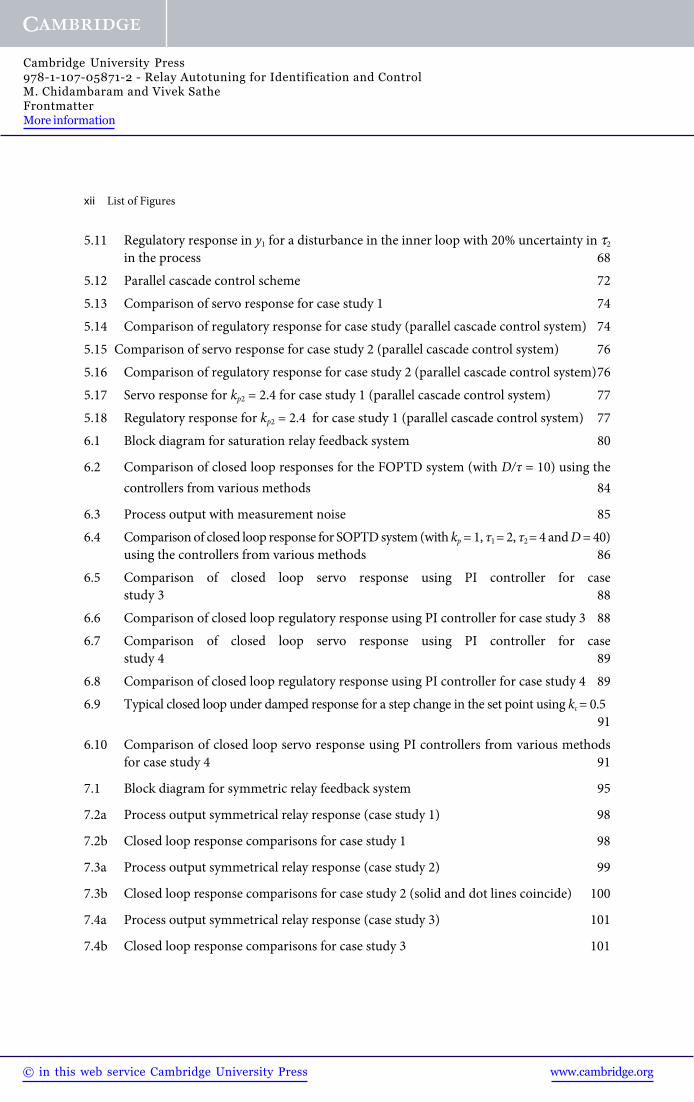
xii List of Figures
5.11 Regulatory response in y1 for a disturbance in the inner loop with 20% uncertainty in t2
in the process 685.12 Parallel cascade control scheme 725.13 Comparison of servo response for case study 1 745.14 Comparison of regulatory response for case study (parallel cascade control system) 745.15 Comparison of servo response for case study 2 (parallel cascade control system) 765.16 Comparison of regulatory response for case study 2 (parallel cascade control system) 765.17 Servo response for kp2 = 2.4 for case study 1 (parallel cascade control system) 775.18 Regulatory response for kp2 = 2.4 for case study 1 (parallel cascade control system) 776.1 Block diagram for saturation relay feedback system 80
6.2 Comparison of closed loop responses for the FOPTD system (with D/τ = 10) using the controllers from various methods 84
6.3 Process output with measurement noise 856.4 Comparison of closed loop response for SOPTD system (with kp = 1, τ1 = 2, τ2 = 4 and D = 40)
using the controllers from various methods 866.5 Comparison of closed loop servo response using PI controller for case
study 3 886.6 Comparison of closed loop regulatory response using PI controller for case study 3 886.7 Comparison of closed loop servo response using PI controller for case
study 4 896.8 Comparison of closed loop regulatory response using PI controller for case study 4 896.9 Typical closed loop under damped response for a step change in the set point using kc = 0.5
916.10 Comparison of closed loop servo response using PI controllers from various methods
for case study 4 91
7.1 Block diagram for symmetric relay feedback system 95
7.2a Process output symmetrical relay response (case study 1) 98
7.2b Closed loop response comparisons for case study 1 98
7.3a Process output symmetrical relay response (case study 2) 99
7.3b Closed loop response comparisons for case study 2 (solid and dot lines coincide) 100
7.4a Process output symmetrical relay response (case study 3) 101
7.4b Closed loop response comparisons for case study 3 101
Cambridge University Press978-1-107-05871-2 - Relay Autotuning for Identification and ControlM. Chidambaram and Vivek SatheFrontmatterMore information
www.cambridge.org© in this web service Cambridge University Press

List of Figures xiii
7.5 Comparison of the closed loop servo response of the controllers on the actual system 103
8.1 Block diagram for symmetric relay feedback system 1078.2a Relay oscillations for (D/t) = 0.2 for case study 1 1128.2b Comparison of set point responses for case study 1 1138.3 Relay oscillations for case study 2 1148.4 Comparison of set point responses for case study 2 1148.5 Comparison of actual response (deviation variable) with that obtained by the Thyagarajan
and Yu method (for non-linear bioreactor problem) 1188.6 Comparison of the responses of the non-linear bioreactor using the controller settings
from different identification methods 1199.1 Block diagram for symmetric relay feedback system 1229.2 q versus twu corresponding to Eq.(9.22) 1269.3 Relay feedback response of case study 1 1299.4 Open loop response comparison for case study 1 1309.5 Closed loop response comparison for case study 1 1319.6 Relay feedback response of case study 2 1329.7 Open loop response of case study 2 1329.8 Closed loop response on the actual system for a step change in set point for case study 2
(controller settings as in Tables 9.3 and 9.6) 1339.9 Relay response of case study 3 1349.10 Open loop response of case study 3. SC method is for FOPTD model 1349.11 Closed loop response for unit step change in set point for case study 3 1359.12 Relay feedback response of bioreactor system 1379.13 Open loop response of a bioreactor system (deviation from initial steady-state
value is plotted for the actual system) 1389.14 Closed loop response for unit step change in set point for a bioreactor system 1389.15 Nyquist plot of the transfer function 14210.1 Block diagram for asymmetric relay feedback system 14410.2a Output response for case study 1 14710.2b Step response for case study 1 14810.3 Step response for case study 2 14810.4 Step response for case study 3 149
Cambridge University Press978-1-107-05871-2 - Relay Autotuning for Identification and ControlM. Chidambaram and Vivek SatheFrontmatterMore information
www.cambridge.org© in this web service Cambridge University Press

xiv List of Figures
10.5 Closed loop response for case study 4 15011.1 Block diagram for asymmetric relay feedback system 15411.2 Process input-output relay response (case study 1) 15811.3 Controllers performance evaluated on the actual system (case study 1) 15811.4 Controllers performance evaluated on the actual system (case study 1, effect of load on
model identification) 15911.5 Process output relay response (case study 2) 16011.6 Controllers performance evaluated on the actual system (case study 2) 16011.7 Process output relay response (case study 3) 16111.8 Controllers performance evaluated on actual system (case study 3) 16111.9 Process asymmetric relay response of the CSTR 16311.10 Closed loop response of actual system for step point in the set point 16312.1 Decentralized relay feedback 16712.2a Comparison of closed loop performance for step change in Y1 17112.2b Comparison of closed loop performance for step change in Y2 17113.1 Comparison of performance of actual and identified models for example 1 18113.2 Comparison of performance of actual and identified models for example 2 18214.1 Control performance of four-tank system for unit step change in y1 18814.2 Control performance of four-tank system for unit step change in y2 18914.3 Control performance of four-tank system for unit step change in V1 18914.4 Control performance of four-tank system for unit step change in V2 19015.1 Convergence of PI controller parameters (1 and 2 represent the controllers C11 and
C22, respectively) 20015.2 Closed loop system response of decentralized controllers for a step change in set point
Y1 (the upper curves show the response and the lower curves show the interaction) 20115.3 Closed loop system response of decentralized controllers for a step change in set point
Y2 (the upper curves show the response and the lower curves show the interaction) 20115.4 Closed loop system response of centralized controllers for a step change in set point Y1
(the upper curves show the response and the lower curves show the interaction) 20215.5 Closed loop system response of centralized controllers for a step change in set point Y2
(the upper curves show the response and the lower curves show the interaction) 203
Figures in AppendicesA.1 Simulink block diagram for inner loop tuning for case study 1 215A.2 Simulink block diagram for outer loop tuning for case study 1 215
Cambridge University Press978-1-107-05871-2 - Relay Autotuning for Identification and ControlM. Chidambaram and Vivek SatheFrontmatterMore information
www.cambridge.org© in this web service Cambridge University Press

List of Figures xv
A.3 Simulink block diagram for measurement noise in inner loop for case study 1 216A.4 Simulink block diagram for parallel cascade control system 216A.5 Simulink block diagram for inner loop and outer loop tuning for case study 1 216A.6 Simulink block diagram for improved relay tuning for case study 1 217A.7 Simulink block diagram for identification for the non-linear continuous bioreactor
system 217A.8 Simulink block diagram for non-linear continuous bioreactor system 218A.9 Simulink block diagram for control of the non-linear CSTR process 218A.10 Simulink block diagram for non-linear CSTR system 219C.1 y*(t*) versus a1m corresponding to Eq.(C.24) 233
Cambridge University Press978-1-107-05871-2 - Relay Autotuning for Identification and ControlM. Chidambaram and Vivek SatheFrontmatterMore information
www.cambridge.org© in this web service Cambridge University Press

Cambridge University Press978-1-107-05871-2 - Relay Autotuning for Identification and ControlM. Chidambaram and Vivek SatheFrontmatterMore information
www.cambridge.org© in this web service Cambridge University Press

List of Tables
2.1 Comparison of estimated ku and identified FOPTD model parameters for the present method (when wt* = p/2) and Li et al. (1991) method 19
2.2a Effect of including higher order harmonics on ku (Eqs 2.19 and 2.22) 202.2b Details of calculations for Table 2.2a 202.2c Effect of including higher order harmonics on ku (use of Eqs 2.33 and 2.22) 202.2d Details of calculations for Table 2.2c 202.3 Closed loop performance comparisons of different methods of identification with that
of the actual system 272.4 PID controller settings and ISE values for case study 4 (unstable system) 293.1 Controller settings comparison for (D/t)inner loop = 4.0, (D/t)outer loop = 4.0 343.2 Performance comparison of proposed methods and the Hang et al. method for
(D/t)inner loop = 4.0, (D/t)outer loop = 4.0 353.3 Effect of change in relay height on PI settings using asymmetric relay testing 363.4 Controller settings comparison for the second example 373.5 Controller settings comparison using the Ziegler–Nichols settings for parallel cascade
control system 413.6 Performance comparison of proposed methods and conventional method for
(D/t)inner loop = 4.0, (D/t)outer loop = 6.0 413.7 Effect of change in relay height using asymmetric relay testing on PI settings for parallel
cascade control system 424.1 Calculation details for proposed method (series cascade control system) 454.2 Controller settings comparison using the Ziegler–Nichols settings (series cascade
control systems) 464.3 Controller settings for simultaneous relay series cascade control system 484.4 Controller settings comparison using Z–N settings (for parallel cascade control
systems) 52
Cambridge University Press978-1-107-05871-2 - Relay Autotuning for Identification and ControlM. Chidambaram and Vivek SatheFrontmatterMore information
www.cambridge.org© in this web service Cambridge University Press

xviii List of Tables
4.5 Performance comparison for parallel cascade control systems 534.6 Controller design comparison for simultaneous relay for parallel cascade control
system 545.1 P/PI Controller settings 625.2 Performance comparison of different methods under perfect parameters 625.3 Controller settings when a1 = 0.9 and a2 = 0.4 a1 (series cascade control system) 635.4 Performance comparison of different methods under perfect parameters 645.5a Performance comparison of the controlled system under uncertainty in kp2 20% high (kp2
= 2.4 in the process and controller designed for kp2 = 2) 665.5b Performance comparison of the controlled system under uncertainty in D2 20% high (D2
= 2.4 in the process and controller designed for D2 = 2) 665.5c Performance comparison of the controlled system under uncertainty in t2 20% high (t2
= 24 in the process and controller designed for t2 = 20) 665.6a Performance comparison of the controlled system under uncertainty in kp1 20% higher
in the process (kp1 = 1.2, a1 = 0.9 and a2 = 0.4 a1) 695.6b Performance comparison of the controlled system under uncertainty in D1 20% higher
in the process (D1 = 12, a1 = 0.9 and a2 = 0.4 a1) 695.6c Performance comparison of the controlled system under uncertainty in t1 20% higher
in the process (t1 = 120, a1 = 0.9 and a2 = 0.4 a1) 695.7 Gain margin (Am) and phase margin (fm) with inner loop P controller and outer loop
PI controller 695.8 Controller settings 735.9 Performance comparison of the controlled system under perfect parameters 755.10 Performance comparison of the controlled system under uncertainty in kp2 (parallel
cascade control system) 756.1 Theoretical value and estimations of the ultimate gain by relay tests for the FOPTD
systems 836.2 PI controller settings for FOPTD system with kp = 1, t = 1 and D = 10 846.3 Identified ku and pu while using noise 856.4 PI controller settings for SOPTD system with kp = 1, t1 = 2, t2 = 4 and D = 40 866.5 PI controller settings using IMC method for case studies 3 and 4 876.6 Comparison of identified model parameters, the designed PI controller parameters
using IMC method and IAE values of the closed loop system for case study 4 907.1 Intermediate values for the examples considered 977.2 Controller parameters based on identified model and actual process parameters 97
Cambridge University Press978-1-107-05871-2 - Relay Autotuning for Identification and ControlM. Chidambaram and Vivek SatheFrontmatterMore information
www.cambridge.org© in this web service Cambridge University Press

List of Tables xix
7.3 Tuning formulae used for case study 3 (Padmasree et al., 2004) 1007.4 Identified parameters of FOPTD model for case study 4 1038.1 Effect of including higher order harmonics on ku 1098.2 Details of calculations for Table 8.1 1108.3 Model parameters identified for unstable FOPTD systems 1128.4 Comparison of identified model parameters and controller parameters for case study 1
1128.5 Effect of measurement noise for case study 2. G(s) = exp(–0.5s)/((0.5s+1)(2s–1)) 1158.6 Effect of load on identification for case studies 1 and 2 1168.7 PID settings for the identified unstable FOPTD model parameters of bioreactor 1189.1 Effect of including higher order harmonics on ku 1249.2 Details of calculations for Table 9.1 1249.3 Identified model parameters and controller settings 1299.4 Effect of measurement noise and load on model identification using the proposed
method 1369.5 Controller performance based on non-linear identified models 1379.6 Identified and controller parameters by the proposed methods for case study 2 14110.1 Intermediate values for the examples considered 14911.1 Intermediate values for the case studies considered 15711.2 Controller parameters based on identified model and actual process parameters 15711.3 Effect of noise and load disturbance on identification for case study 1 15811.4 Controller parameters and ISE and IAE values for the CSTR control problem 16412.1 ISE value comparison for actual and identified models for the above examples 17213.1 Closed loop ISE values comparison between the identified model and actual
system for example 1 17913.2 Closed loop ISE values comparison for the actual and identified models for example 2
18014.1 ISE values of servo and regulatory problem for four-tank liquid level system 19114.2 ISE values for robustness analysis (perturbation in all the steady-state gains) 19114.3a ISE values of servo problem for the examples 2 and 3 19314.3b ISE values of regulatory problem for the examples 2 and 3 19415.1 Optimal PI controller parameters for decentralized control system 19815.2 Optimal PI controller parameters for centralized control system 203
Cambridge University Press978-1-107-05871-2 - Relay Autotuning for Identification and ControlM. Chidambaram and Vivek SatheFrontmatterMore information
www.cambridge.org© in this web service Cambridge University Press

xx List of Tables
15.3 Optimal PI controller parameters for example 2 using the improved GA andthe Vlachos et al. method 205
Tables in AppendicesC.1 Estimated parameters of the integrating FOPTD model by the proposed methods 236C.2 Effect of including higher order harmonics on ku 236C.3 Details of calculations for Table C.2 237
Cambridge University Press978-1-107-05871-2 - Relay Autotuning for Identification and ControlM. Chidambaram and Vivek SatheFrontmatterMore information
www.cambridge.org© in this web service Cambridge University Press

Acknowledgements
The authors owe a debt of gratitude to many friends, colleagues and students who helped us write this book. First of all, we gratefully acknowledge the contributions made by the graduate students – K. Sinivasan, V. Ramakrishnan, D.S. Ganesh, E. Sivakumar, D.S. Reddy, M.V. Sadasivarao – as part of their project works. We are also thankful for the support received from the Department of Chemical Engineering and the Continuing Education Centre, Indian Institute of Technology, Madras. The second author expresses his sincere appreciation to his son C. Srihari Prasath for his patience and understanding while writing the manuscript.
It would also be appropriate to express our regards to R. Mohan of Sigma Publishing who drew the figures of the book. We would be remiss if we did not thank Cambridge University Press and our editors involved in the process for their efficient professionalism and successfully bringing out the book.
Cambridge University Press978-1-107-05871-2 - Relay Autotuning for Identification and ControlM. Chidambaram and Vivek SatheFrontmatterMore information
www.cambridge.org© in this web service Cambridge University Press

Cambridge University Press978-1-107-05871-2 - Relay Autotuning for Identification and ControlM. Chidambaram and Vivek SatheFrontmatterMore information
www.cambridge.org© in this web service Cambridge University Press

Preface
To design proportional plus integral (PI)/PID controllers, the ultimate values of the controller gain (ku) and frequency of oscillation (wu) should be known. The conventional Ziegler and Nichols continuous cycling method requires a large number of experiments to calculate these values. Åström and Hägglund (1984) suggested the use of ideal relay to generate closed loop oscillations. The ultimate gain and ultimate frequency can be found in a single-shot experiment. However, the method is still approximate because of the use of the principal harmonics approximation. Li et al. (1991) reported that for an open loop, stable first order plus time delay (FOPTD) system, an error of -18% to 27% is obtained in the calculation of ku. Yu (1999) suggested a saturation feedback test to get better results for the ultimate gain and frequency. However, Yu (1999) did not report any result for large values of delay-to-time constant ratio.
An SOPTD model can incorporate higher order process dynamics better than an FOPTD model. The controller designed on the basis of the SOPTD model gives a better closed loop response than the one designed on an FOPTD model. It is better to have an SOPTD model with equal time constants since only three parameters are to be identified. Li et al. (1991) showed that the conventional analysis of the relay autotune method for an SOPTD model with equal time constants gives -11% to 27% error in the calculation of ku. In identifying the transfer function models for unstable systems, it is necessary to estimate 5 parameters to describe such systems. There is no method available to estimate these parameters from a single relay test. Cascade control system is a multi-loop control scheme commonly used in the chemical process industries. It should be noted that there are two ways of relay tuning cascade control systems, namely, simultaneous tuning and sequential tuning procedures. However, there is a need to consider higher order harmonics in the analysis of relay tuning of such systems to obtain improved controllers settings.The authors have organized the book in the following manner:Chapter 1 gives an overview of the reported works on relay tuning of single loop control system, cascade controllers, estimation of model parameters and design of PI/PID controllers. Chapter 2 gives a method of considering higher order harmonics in the analysis of symmetric relay tuning method and analytical solutions for model parameters using a single asymmetrical relay test.
Chapter 3 gives a method of considering higher order harmonics in the analysis of series cascade control systems by the sequential tuning method. The method is also extended to
Cambridge University Press978-1-107-05871-2 - Relay Autotuning for Identification and ControlM. Chidambaram and Vivek SatheFrontmatterMore information
www.cambridge.org© in this web service Cambridge University Press

xxiv Preface
parallel cascade control systems. Chapter 4 analyzes the simultaneous relay tuning of series and parallel cascade control systems.
Chapter 5 gives a simple method to design PID controllers for a series cascade control system. FOPTD models are assumed for both the inner and outer loop sub-systems. The method is based on matching the coefficients of the corresponding powers of s and s2 in the numerator to a1 and a2 times that in the denominator of the closed loop transfer function model for a servo problem. The method is first applied to design a proportional (P) controller for the inner loop and then to design a proportional plus integral (PI) controller for the outer loop. The performance of the proposed controllers is evaluated for FOPTD models of the inner loop and the outer loop process transfer functions. This method is also extended to parallel cascade control systems.
Chapter 6 proposes two methods to improve the accuracy of the saturation relay method for FOPTD systems with a large ratio of time delay to time constant. Chapter 7 proposes a method to identify all the three parameters of a first order plus time delay (FOPTD) model using a single symmetrical relay test.
Chapter 8 gives a method to identify all the three parameters of an unstable FOPTD system using a single symmetric relay feedback test. It also proposes a method by incorporating higher order harmonics to explain the error in the calculation of ku. Another method is proposed to estimate all the parameters of an unstable FOPTD system.
In Chapter 9, using a single symmetric relay feedback test, a method is proposed to identify all the three parameters of a stable second order plus time delay (SOPTD) model with equal time constants [kp exp(–Ds)/(ts+1)2]. It provides a method to improve the accuracy in the ku
calculation by incorporating the higher order harmonics.In Chapter 10, using a single asymmetric relay feedback test, a method is proposed to identify
all the four parameters of a stable second order plus time delay (SOPTD) model kp exp(–Ds)/[(t1s+1) (t2 s+1)]. In Chapter 11, a method is proposed to identify all the 5 parameters of an SOPTD system with a zero, G(s) = kp (t1 s+1) exp(–Ds)/[(t2 s+1)(t3 s–1)], using an asymmetric relay test.
In Chapter 12, the asymmetrical relay tuning method is extended to multivariable FOPTD systems. In Chapter 13, the asymmetrical relay tuning method is extended to multivariable SOPTD systems. Chapter 14 proposes a simple method of designing centralized multivariable PID controllers for multivariable systems. In Chapter 15, the use of detuned Ziegler–Nichols PID settings as initial guess values is suggested for the design of multivariable controllers by an optimization method using the genetic algorithm to reduce the number of iterations significantly. Chapter 16 summarizes the results and conclusions of the work.
There are three appendices. Appendix A gives the Simulink block diagrams used in the present work.Appendix B gives the Matlab programs used in Chapter 3, Chapter 5 and Chapter 6.Appendix C gives an improved relay tuning method for integrating plus FOPTD systems.
Cambridge University Press978-1-107-05871-2 - Relay Autotuning for Identification and ControlM. Chidambaram and Vivek SatheFrontmatterMore information
www.cambridge.org© in this web service Cambridge University Press