Embed Size (px)
Citation preview
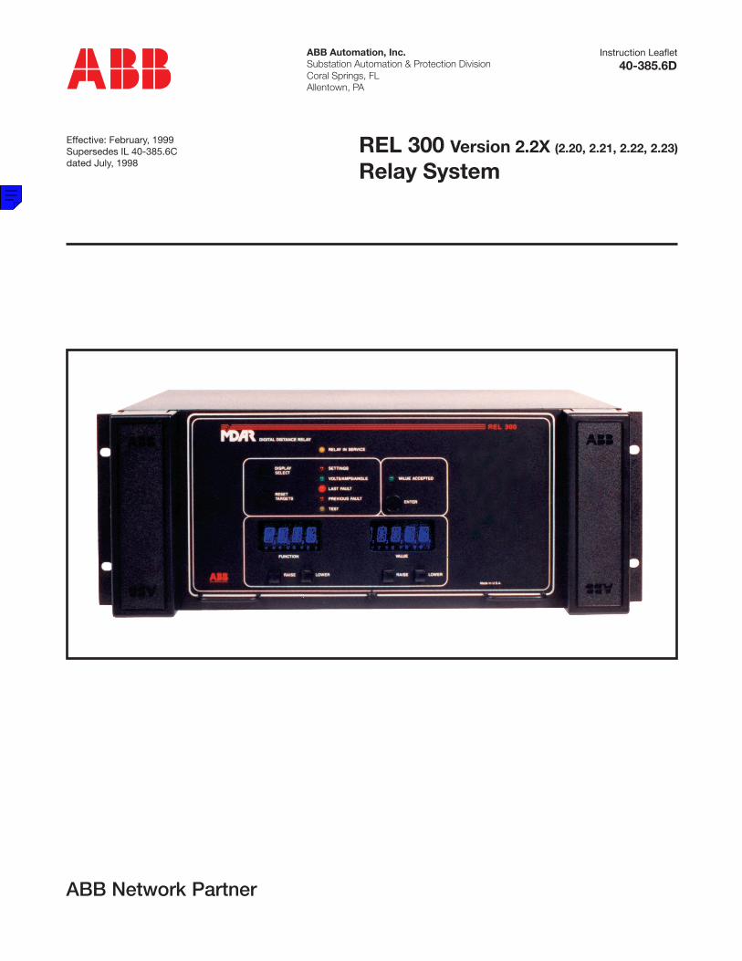
ABB Automation, Inc.Substation Automation & Protection DivisionCoral Springs, FLAllentown, PA
Instruction Leaflet
Effective: February, 1999Supersedes IL 40-385.6Cdated July, 1998
REL 300 Version 2.2X (2.20, 2.21, 2.22, 2.23)
Relay System
40-385.6D
ABB Network Partner

For Firmware Versions
REL300Relay system
2.20, 2.21, 2.22, 2.23
I.L. 40-385.6
REL300 REVISION NOTICE
DATE REV. LEVEL PAGES REMOVED PAGES INSERTED
4/96 A --- ---
1/97 B X, 2-14, 3-3, 3-6, 3-7, 3-8,3-9, 3-11, 3-12, 3-14, 3-19,3-21, 3-33, 3-44, 5-2, 6-9,6-10, 6-11, 7-2, SD-2,SD3, SD-4, SD-5
X, 2-14, 3-3, 3-6, 3-7, 3-8, 3-9,3-11, 3-12, 3-14, 3-19, 3-21,3-33, 3-44, 5-2, 6-9, 6-10, 6-11,7-2, SD-2, SD-3, SD-4, SD-5
4/98 C Shown by change bars Shown by change bars
2/99 D Consolidated Versions New Page 61
CHANGE SUMMARY:
A CHANGE BAR ( ) LOCATED IN THE MARGIN REPRESENTS ATECHNICAL CHANGE TO THE PRODUCT.
A STAR (*) LOCATED BY THE SUB NUMBER REPRESENTS ATECHNICAL CHANGE TO THE DRAWING.
i
I.L. 40-385.6
It is recommended that the user of REL300 equipment become acquainted with the information in this instructionleaflet before energizing the system. Failure to do so may result in injury to personnel or damage to the equipment,and may affect the equipment warranty. If the REL300 relay system is mounted in a cabinet, the cabinet must bebolted to the floor, or otherwise secured before REL300 installation to prevent the system from tipping over.
All integrated circuits used on the modules are sensitive to and can be damaged by the discharge of static electricity.Electrostatic discharge precautions should be observed when handling modules or individual components.
ABB does not assume liability arising out of the application or use of any product or circuit described herein. ABBreserves the right to make changes to any products herein to improve reliability, function or design. Specificationsand information herein are subject to change without notice. All possible contingencies which may arise during in-stallation, operation, or maintenance, and all details and variations of this equipment do not purport to be coveredby these instructions. If further information is desired by purchaser regarding a particular installation, operation ormaintenance of equipment, the local ABB representative should be contacted.
! CAUTION
ii
Copyright © ASEA BROWN BOVERI, ABB Power T&D Company Inc.1990, 1991, 1992,1993, 1994, 1995, 1996, 1997, 1998
This document contains information that is protected by copyright. All rights are reserved. Reproduction, adaptation, or translation without prior writtenpermission is prohibited, except as allowed under the copyright laws.
ABB does not convey any license under its patent rights nor the rights of others.
Trademarks
All terms mentioned in this book that are known to be trademarks or service marks are listedbelow. In addition, terms suspected of being trademarks or service marks have been appropri-ately capitalized. ABB Power T&D Company Inc. cannot attest to the accuracy of this informa-tion. Use of a term in this book should not be regarded as affecting the validity of any trademarkor service mark.
IBM and PC are registered trademarks of the International Business Machines CorporationWRELCOM is the registered trademark of the ABB Power T&D Company Inc.INCOM is the registered trademark of the Westinghouse Electric Corporation
I.L. 40-385.6
PREFACE
Scope
This manual describes the functions and features of the REL300 Relay System. It is intended primarily for use byengineers and technicians involved in the installation, testing, operation and maintenance of the REL300 system.
Equipment Identification
The REL300 equipment is identified by the Catalog Number on the REL300 chassis nameplate. The Catalog Num-ber can be decoded by using Catalog Number Table 3-1.
Production Changes
When engineering and production changes are made to the REL300 equipment, a revision notation (SUB #) is re-flected on the appropriate schematic diagram, and associated parts information.
Equipment Repair
Repair work is done most satisfactorily at the factory. When returning equipment, carefully pack modules and otherunits, etc. All equipment should be returned in the original packing containers if possible. Any damage due to im-properly packed items will be charged to the customer.
Document Overview
The circuitry is divided into six (6) standard modules and one option module. Section 1 provides the Product De-scription, which includes software functions. Section 2 presents the Specifications. Section 3 presents Pilot andNon-Pilot applications with related Catalog Numbers for ordering purposes. REL300 Installation, Operation andMaintenance are described in Section 4, with related Setting Calculations in Section 5. Full Performance Tests arefound in Section 6 and Acceptance/Maintenance Tests in Section 7. The Index gives a complete Index to Nomen-clature. System Diagrams are included at the back of this manual.
Contents of Relay System
The REL300 Relay System includes the style numbers, listed below. Addenda pages may be included (representingfuture revisions).
Module Style
• Backplane 1609C23(Sub-Backplane Xfmr) 1498B70
• Interconnect 1611C30
• Option 1608C39
• Filter 1608C38
• Microprocessor 1611C14
• Display 1609C01
• Power Supply 1608C35
Software System
REL300 software versions 2.20, 2.21, 2.22, 2.23 are included in this I.L.
iii
I.L. 40-385.6
iv
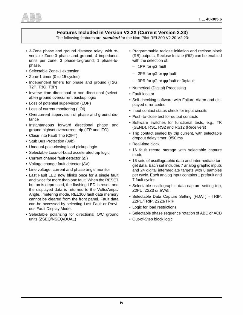
• 3-Zone phase and ground distance relay, with re-versible Zone-3 phase and ground; 4 impedanceunits per zone: 3 phase-to-ground; 1 phase-to-phase.
• Selectable Zone-1 extension• Zone-1 timer (0 to 15 cycles)• Independent timers for phase and ground (T2G,
T2P, T3G, T3P)• Inverse time directional or non-directional (select-
able) ground overcurrent backup logic• Loss of potential supervision (LOP)• Loss of current monitoring (LOI)• Overcurrent supervision of phase and ground dis-
tance• Instantaneous forward directional phase and
ground highset overcurrent trip (ITP and ITG)• Close Into Fault Trip (CIFT)• Stub Bus Protection (89b)• Unequal-pole-closing load pickup logic• Selectable Loss-of-Load accelerated trip logic• Current change fault detector (∆I)• Voltage change fault detector (∆V)• Line voltage, current and phase angle monitor• Last Fault LED now blinks once for a single fault
and twice for more than one fault. When the RESETbutton is depressed, the flashing LED is reset, andthe displayed data is returned to the Volts/Amps/Angle...metering mode. REL300 fault data memorycannot be cleared from the front panel. Fault datacan be accessed by selecting Last Fault or Previ-ous Fault Display Mode.
• Selectable polarizing for directional O/C groundunits (ZSEQ/NSEQ/DUAL)
• Programmable reclose initiation and reclose block(RB) outputs; Reclose Initiate (RI2) can be enabledwith the selection of:
– 1PR for φG fault
– 2PR for φG or φφ fault
– 3PR for φG or φφ fault or 3φ fault
• Numerical (Digital) Processing
• Fault locator
• Self-checking software with Failure Alarm and dis-played error codes
• Input contact status check for input circuits
• Push-to-close test for output contacts
• Software switches for functional tests, e.g., TK(SEND), RS1, RS2 and RS12 (Receivers)
• Trip contact sealed by trip current, with selectabledropout delay timer, 0/50 ms
• Real-time clock
• 16 fault record storage with selectable capturemode
• 16 sets of oscillographic data and intermediate tar-get data. Each set includes 7 analog graphic inputsand 24 digital intermediate targets with 8 samplesper cycle. Each analog input contains 1 prefault and7 fault cycles
• Selectable oscillographic data capture setting trip,Z2PU, Z2Z3 or ∆V/∆I.
• Selectable Data Capture Setting (FDAT) - TRIP,Z2PU/TRIP, Z2Z3/TRIP
• Logic for load restrictions
• Selectable phase sequence rotation of ABC or ACB
• Out-of-Step block logic
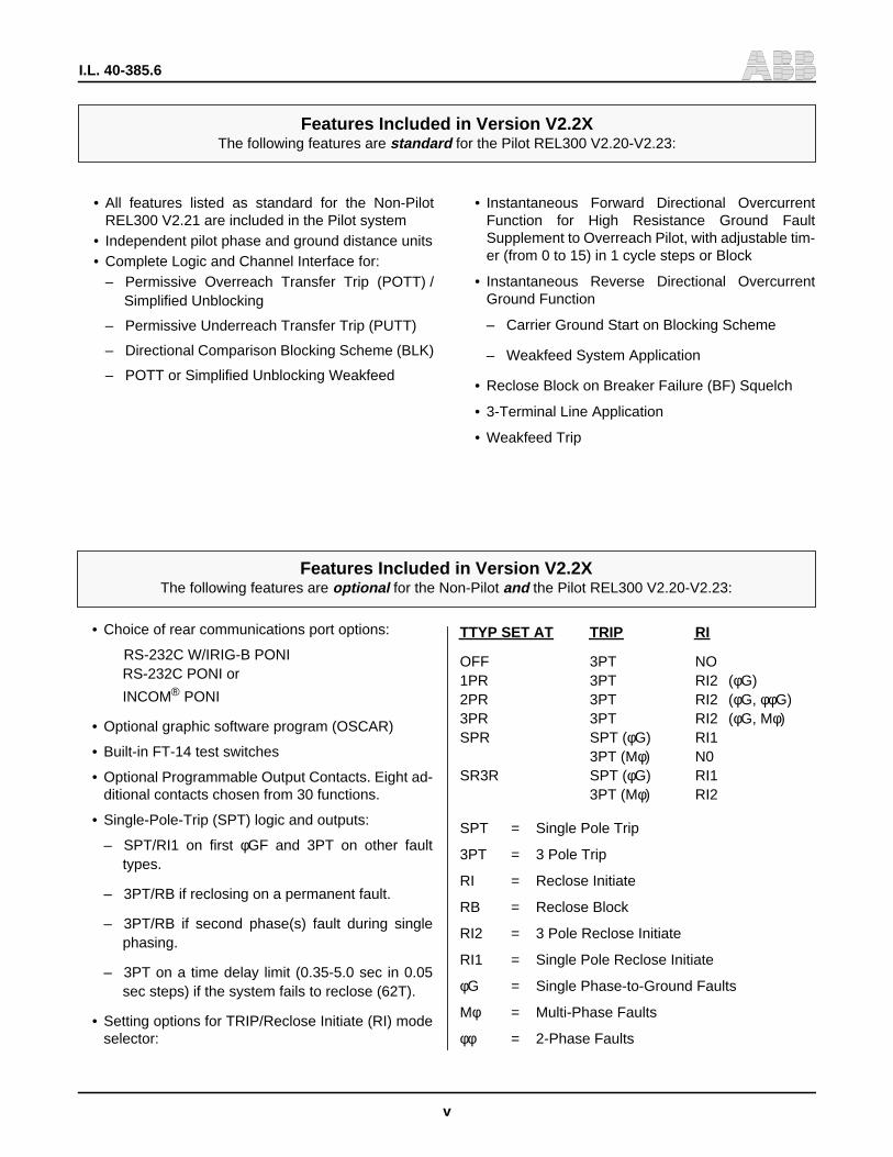
Features Included in Version V2.2X (Current Version 2.23)The following features are standard for the Non-Pilot REL300 V2.20-V2.23:
v
I.L. 40-385.6
• All features listed as standard for the Non-PilotREL300 V2.21 are included in the Pilot system
• Independent pilot phase and ground distance units• Complete Logic and Channel Interface for:
– Permissive Overreach Transfer Trip (POTT) /Simplified Unblocking
– Permissive Underreach Transfer Trip (PUTT)
– Directional Comparison Blocking Scheme (BLK)
– POTT or Simplified Unblocking Weakfeed
• Instantaneous Forward Directional OvercurrentFunction for High Resistance Ground FaultSupplement to Overreach Pilot, with adjustable tim-er (from 0 to 15) in 1 cycle steps or Block
• Instantaneous Reverse Directional OvercurrentGround Function
– Carrier Ground Start on Blocking Scheme
– Weakfeed System Application
• Reclose Block on Breaker Failure (BF) Squelch
• 3-Terminal Line Application
• Weakfeed Trip
• Choice of rear communications port options:
RS-232C W/IRIG-B PONIRS-232C PONI or
INCOM® PONI
• Optional graphic software program (OSCAR)
• Built-in FT-14 test switches
• Optional Programmable Output Contacts. Eight ad-ditional contacts chosen from 30 functions.
• Single-Pole-Trip (SPT) logic and outputs:
– SPT/RI1 on first φGF and 3PT on other faulttypes.
– 3PT/RB if reclosing on a permanent fault.
– 3PT/RB if second phase(s) fault during singlephasing.
– 3PT on a time delay limit (0.35-5.0 sec in 0.05sec steps) if the system fails to reclose (62T).
• Setting options for TRIP/Reclose Initiate (RI) modeselector:
TTYP SET AT TRIP RI
OFF 3PT NO1PR 3PT RI2 (φG)2PR 3PT RI2 (φG, φφG)3PR 3PT RI2 (φG, Mφ)SPR SPT (φG) RI1
3PT (Mφ) N0SR3R SPT (φG) RI1
3PT (Mφ) RI2
SPT = Single Pole Trip
3PT = 3 Pole Trip
RI = Reclose Initiate
RB = Reclose Block
RI2 = 3 Pole Reclose Initiate
RI1 = Single Pole Reclose Initiate
φG = Single Phase-to-Ground Faults
Mφ = Multi-Phase Faults
φφ = 2-Phase Faults
Features Included in Version V2.2XThe following features are standard for the Pilot REL300 V2.20-V2.23:
Features Included in Version V2.2XThe following features are optional for the Non-Pilot and the Pilot REL300 V2.20-V2.23:
I.L. 40-385.6
vi
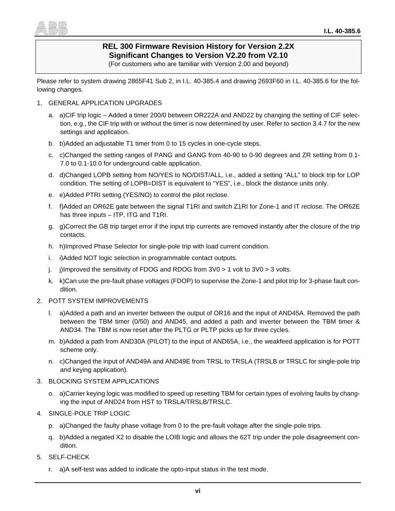
Please refer to system drawing 2865F41 Sub 2, in I.L. 40-385.4 and drawing 2693F60 in I.L. 40-385.6 for the fol-lowing changes.
1. GENERAL APPLICATION UPGRADES
a. a)CIF trip logic – Added a timer 200/0 between OR222A and AND22 by changing the setting of CIF selec-tion, e.g., the CIF trip with or without the timer is now determined by user. Refer to section 3.4.7 for the newsettings and application.
b. b)Added an adjustable T1 timer from 0 to 15 cycles in one-cycle steps.
c. c)Changed the setting ranges of PANG and GANG from 40-90 to 0-90 degrees and ZR setting from 0.1-7.0 to 0.1-10.0 for underground cable application.
d. d)Changed LOPB setting from NO/YES to NO/DIST/ALL, i.e., added a setting “ALL” to block trip for LOPcondition. The setting of LOPB=DIST is equivalent to “YES”, i.e., block the distance units only.
e. e)Added PTRI setting (YES/NO) to control the pilot reclose.
f. f)Added an OR62E gate between the signal T1RI and switch Z1RI for Zone-1 and IT reclose. The OR62Ehas three inputs – ITP, ITG and T1RI.
g. g)Correct the GB trip target error if the input trip currents are removed instantly after the closure of the tripcontacts.
h. h)Improved Phase Selector for single-pole trip with load current condition.
i. i)Added NOT logic selection in programmable contact outputs.
j. j)Improved the sensitivity of FDOG and RDOG from 3V0 > 1 volt to 3V0 > 3 volts.
k. k)Can use the pre-fault phase voltages (FDOP) to supervise the Zone-1 and pilot trip for 3-phase fault con-dition.
2. POTT SYSTEM IMPROVEMENTS
l. a)Added a path and an inverter between the output of OR16 and the input of AND45A. Removed the pathbetween the TBM timer (0/50) and AND45, and added a path and inverter between the TBM timer &AND34. The TBM is now reset after the PLTG or PLTP picks up for three cycles.
m. b)Added a path from AND30A (PILOT) to the input of AND65A, i.e., the weakfeed application is for POTTscheme only.
n. c)Changed the input of AND49A and AND49E from TRSL to TRSLA (TRSLB or TRSLC for single-pole tripand keying application).
3. BLOCKING SYSTEM APPLICATIONS
o. a)Carrier keying logic was modified to speed up resetting TBM for certain types of evolving faults by chang-ing the input of AND24 from HST to TRSLA/TRSLB/TRSLC.
4. SINGLE-POLE TRIP LOGIC
p. a)Changed the faulty phase voltage from 0 to the pre-fault voltage after the single-pole trips.
q. b)Added a negated X2 to disable the LOIB logic and allows the 62T trip under the pole disagreement con-dition.
5. SELF-CHECK
r. a)A self-test was added to indicate the opto-input status in the test mode.
REL 300 Firmware Revision History for Version 2.2XSignificant Changes to Version V2.20 from V2.10(For customers who are familiar with Version 2.00 and beyond)
vii
I.L. 40-385.6
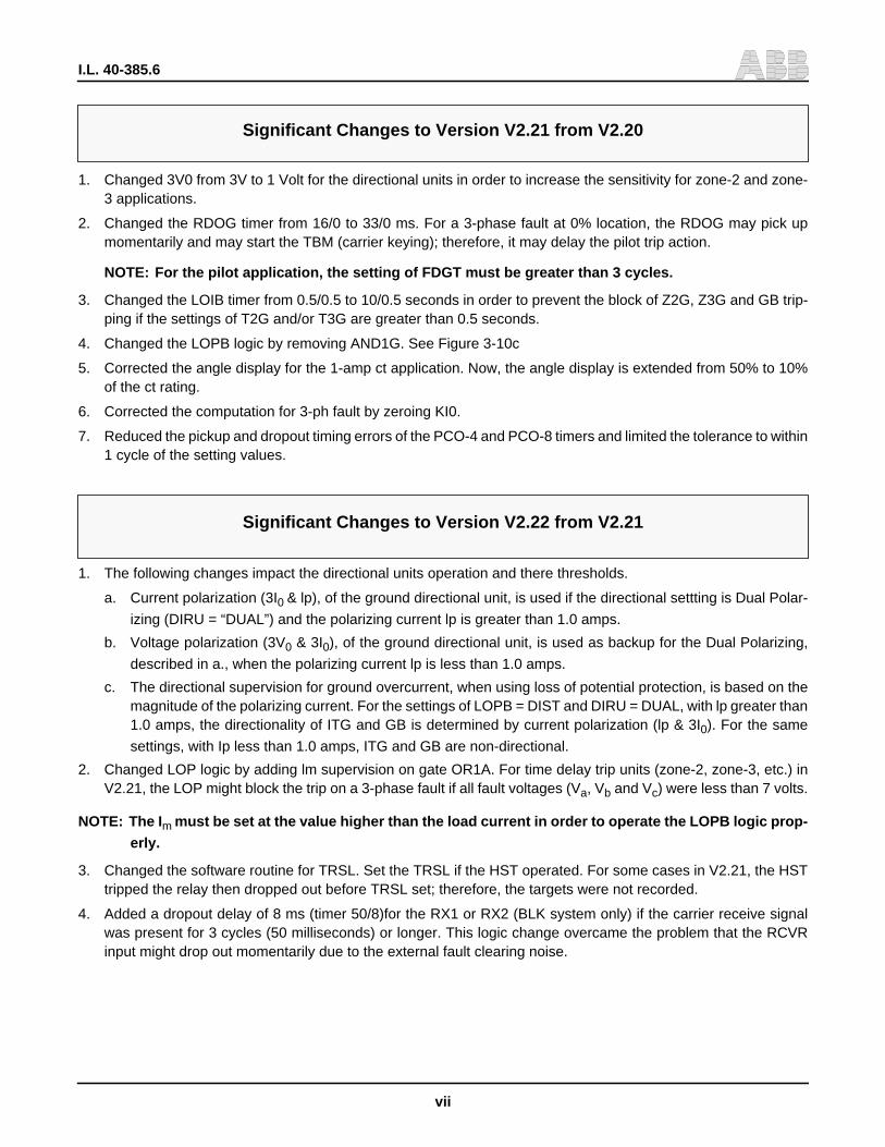
1. Changed 3V0 from 3V to 1 Volt for the directional units in order to increase the sensitivity for zone-2 and zone-3 applications.
2. Changed the RDOG timer from 16/0 to 33/0 ms. For a 3-phase fault at 0% location, the RDOG may pick upmomentarily and may start the TBM (carrier keying); therefore, it may delay the pilot trip action.
NOTE: For the pilot application, the setting of FDGT must be greater than 3 cycles.
3. Changed the LOIB timer from 0.5/0.5 to 10/0.5 seconds in order to prevent the block of Z2G, Z3G and GB trip-ping if the settings of T2G and/or T3G are greater than 0.5 seconds.
4. Changed the LOPB logic by removing AND1G. See Figure 3-10c
5. Corrected the angle display for the 1-amp ct application. Now, the angle display is extended from 50% to 10%of the ct rating.
6. Corrected the computation for 3-ph fault by zeroing KI0.
7. Reduced the pickup and dropout timing errors of the PCO-4 and PCO-8 timers and limited the tolerance to within1 cycle of the setting values.
Significant Changes to Version V2.21 from V2.20
Significant Changes to Version V2.22 from V2.21
1. The following changes impact the directional units operation and there thresholds.
a. Current polarization (3I0 & lp), of the ground directional unit, is used if the directional settting is Dual Polar-
izing (DIRU = “DUAL”) and the polarizing current lp is greater than 1.0 amps.
b. Voltage polarization (3V0 & 3I0), of the ground directional unit, is used as backup for the Dual Polarizing,
described in a., when the polarizing current lp is less than 1.0 amps.
c. The directional supervision for ground overcurrent, when using loss of potential protection, is based on themagnitude of the polarizing current. For the settings of LOPB = DIST and DIRU = DUAL, with lp greater than1.0 amps, the directionality of ITG and GB is determined by current polarization (lp & 3I0). For the same
settings, with Ip less than 1.0 amps, ITG and GB are non-directional.
2. Changed LOP logic by adding lm supervision on gate OR1A. For time delay trip units (zone-2, zone-3, etc.) inV2.21, the LOP might block the trip on a 3-phase fault if all fault voltages (Va, Vb and Vc) were less than 7 volts.
NOTE: The Im must be set at the value higher than the load current in order to operate the LOPB logic prop-erly.
3. Changed the software routine for TRSL. Set the TRSL if the HST operated. For some cases in V2.21, the HSTtripped the relay then dropped out before TRSL set; therefore, the targets were not recorded.
4. Added a dropout delay of 8 ms (timer 50/8)for the RX1 or RX2 (BLK system only) if the carrier receive signalwas present for 3 cycles (50 milliseconds) or longer. This logic change overcame the problem that the RCVRinput might drop out momentarily due to the external fault clearing noise.

I.L. 40-385.6
viii
Significant Changes to Version V2.23 (from V2.22)
1. LOP logic were changed as follows:
a. (a)Removed the Im supervision from the gate OR1A. For the V2.22, the LOPB circuit will not block the trip
under the LOP condition if the setting of Im is lower than the load current.
b. (b)Added a dropout delay timer (0/16) between AND223 and OR221 in order to seal-in the AND220. Forthe V2.21 or older versions, the time delay trip units (zone-2, zone-3 and GB) might be blocked by the LOPlogic on a 3-phase fault with all fault voltages (Va, Vb, Vc) below 7 volts.
c. (c)Added an inverted LOP (0/500) to supervise the AND220. This means the distance units will be blockedfor 500 ms after the LOPB condition is removed.
2. Added a transient block ITG timer of 2 cycles if a forward fault occurs immediately after a reverse fault to avoidthe false trip during the clearing of the reverse fault.
ix
I.L. 40-385.6
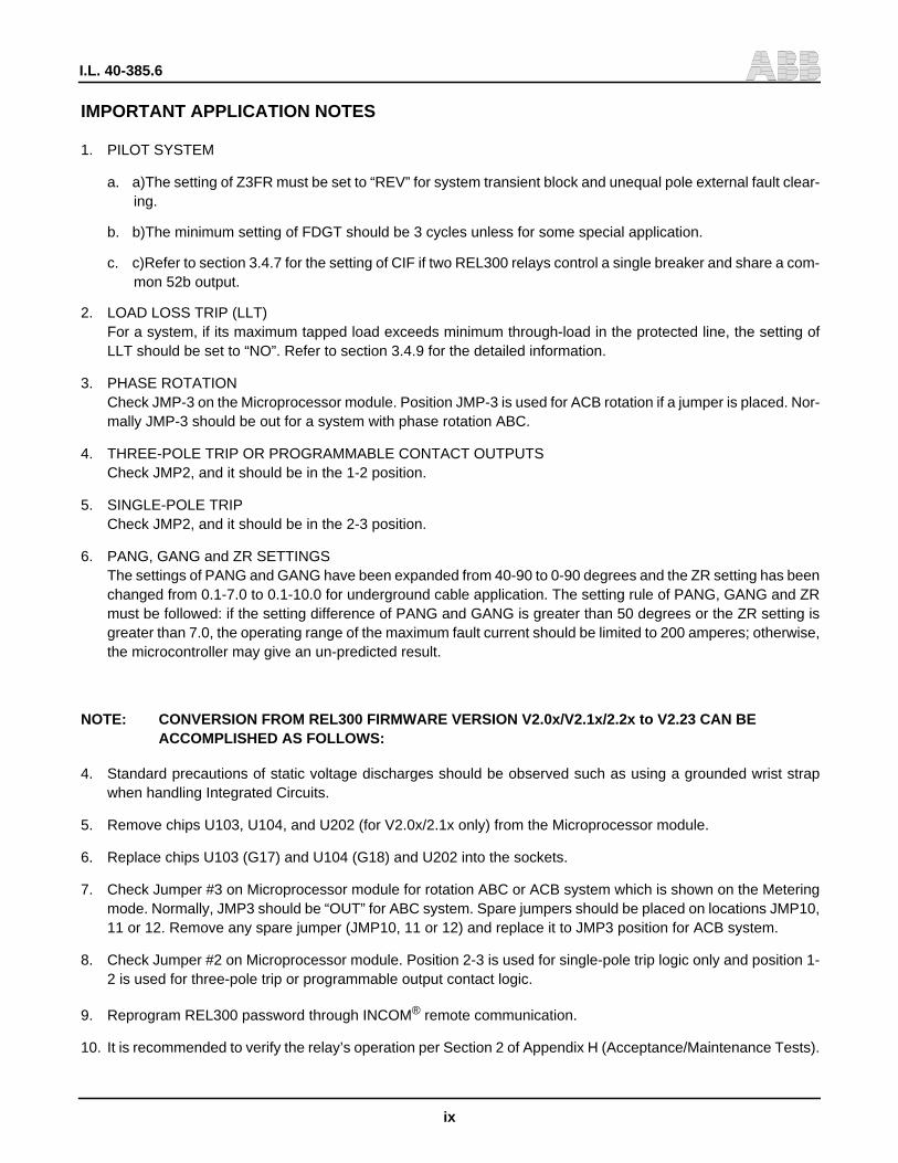
IMPORTANT APPLICATION NOTES
1. PILOT SYSTEM
a. a)The setting of Z3FR must be set to “REV” for system transient block and unequal pole external fault clear-ing.
b. b)The minimum setting of FDGT should be 3 cycles unless for some special application.
c. c)Refer to section 3.4.7 for the setting of CIF if two REL300 relays control a single breaker and share a com-mon 52b output.
2. LOAD LOSS TRIP (LLT)For a system, if its maximum tapped load exceeds minimum through-load in the protected line, the setting ofLLT should be set to “NO”. Refer to section 3.4.9 for the detailed information.
3. PHASE ROTATIONCheck JMP-3 on the Microprocessor module. Position JMP-3 is used for ACB rotation if a jumper is placed. Nor-mally JMP-3 should be out for a system with phase rotation ABC.
4. THREE-POLE TRIP OR PROGRAMMABLE CONTACT OUTPUTSCheck JMP2, and it should be in the 1-2 position.
5. SINGLE-POLE TRIPCheck JMP2, and it should be in the 2-3 position.
6. PANG, GANG and ZR SETTINGSThe settings of PANG and GANG have been expanded from 40-90 to 0-90 degrees and the ZR setting has beenchanged from 0.1-7.0 to 0.1-10.0 for underground cable application. The setting rule of PANG, GANG and ZRmust be followed: if the setting difference of PANG and GANG is greater than 50 degrees or the ZR setting isgreater than 7.0, the operating range of the maximum fault current should be limited to 200 amperes; otherwise,the microcontroller may give an un-predicted result.
NOTE: CONVERSION FROM REL300 FIRMWARE VERSION V2.0x/V2.1x/2.2x to V2.23 CAN BEACCOMPLISHED AS FOLLOWS:
4. Standard precautions of static voltage discharges should be observed such as using a grounded wrist strapwhen handling Integrated Circuits.
5. Remove chips U103, U104, and U202 (for V2.0x/2.1x only) from the Microprocessor module.
6. Replace chips U103 (G17) and U104 (G18) and U202 into the sockets.
7. Check Jumper #3 on Microprocessor module for rotation ABC or ACB system which is shown on the Meteringmode. Normally, JMP3 should be “OUT” for ABC system. Spare jumpers should be placed on locations JMP10,11 or 12. Remove any spare jumper (JMP10, 11 or 12) and replace it to JMP3 position for ACB system.
8. Check Jumper #2 on Microprocessor module. Position 2-3 is used for single-pole trip logic only and position 1-2 is used for three-pole trip or programmable output contact logic.
9. Reprogram REL300 password through INCOM® remote communication.
10. It is recommended to verify the relay’s operation per Section 2 of Appendix H (Acceptance/Maintenance Tests).
I.L. 40-385.6
x
Section 1. PRODUCT DESCRIPTION- - - - - - - - - - - - - - - - - - - - - - - - - - - - - - -1
1.1 INTRODUCTION - - - - - - - - - - - - - - - - - - - - - - - - - - - - - - - - - - - - - - - - - - - - 1
1.2 REL300 CONSTRUCTION - - - - - - - - - - - - - - - - - - - - - - - - - - - - - - - - - - - - - - - 1
1.3 REL300 MODULES - - - - - - - - - - - - - - - - - - - - - - - - - - - - - - - - - - - - - - - - - - 2
1.3.1 Backplane Module - - - - - - - - - - - - - - - - - - - - - - - - - - - - - - - - - - - - - - 2
1.3.2 Interconnect Module - - - - - - - - - - - - - - - - - - - - - - - - - - - - - - - - - - - - - 2
1.3.3 Option Module/Contact Module - - - - - - - - - - - - - - - - - - - - - - - - - - - - - - - - 3
1.3.4 Filter Module - - - - - - - - - - - - - - - - - - - - - - - - - - - - - - - - - - - - - - - - - 3
1.3.5 Microprocessor Module - - - - - - - - - - - - - - - - - - - - - - - - - - - - - - - - - - - - 3
1.3.6 Display Module - - - - - - - - - - - - - - - - - - - - - - - - - - - - - - - - - - - - - - - - 3
1.3.7 Power Supply Module - - - - - - - - - - - - - - - - - - - - - - - - - - - - - - - - - - - - - 4
1.3.8 Contact Outputs- - - - - - - - - - - - - - - - - - - - - - - - - - - - - - - - - - - - - - - - 4
1.4 TEST ACCESSORIES - - - - - - - - - - - - - - - - - - - - - - - - - - - - - - - - - - - - - - - - - 4
1.5 FAULT DETECTION SOFTWARE - - - - - - - - - - - - - - - - - - - - - - - - - - - - - - - - - - - 4
1.5.1 Background Mode- - - - - - - - - - - - - - - - - - - - - - - - - - - - - - - - - - - - - - - 5
1.5.2 Fault Mode and Restricted Fault Tests - - - - - - - - - - - - - - - - - - - - - - - - - - - - 5
1.5.3 Unique Qualities of REL300 - - - - - - - - - - - - - - - - - - - - - - - - - - - - - - - - - - 6
1.6 SELF-CHECKING SOFTWARE - - - - - - - - - - - - - - - - - - - - - - - - - - - - - - - - - - - - 6
1.7 UNIQUE REMOTE COMMUNICATION PROGRAM (RCP) - - - - - - - - - - - - - - - - - - - - - - - 7
1.8 POWER SYSTEM ROTATION ABC OR ACB SELECTION - - - - - - - - - - - - - - - - - - - - - - - 7
Section 2. SPECIFICATIONS - - - - - - - - - - - - - - - - - - - - - - - - - - - - - - - - - - 11
2.1 TECHNICAL - - - - - - - - - - - - - - - - - - - - - - - - - - - - - - - - - - - - - - - - - - - - - -11
2.2 EXTERNAL CONNECTIONS- - - - - - - - - - - - - - - - - - - - - - - - - - - - - - - - - - - - - -11
2.3 CONTACT DATA - - - - - - - - - - - - - - - - - - - - - - - - - - - - - - - - - - - - - - - - - - -12
2.4 MEASUREMENTS - - - - - - - - - - - - - - - - - - - - - - - - - - - - - - - - - - - - - - - - - - -12
2.5 MEASUREMENT UNITS - - - - - - - - - - - - - - - - - - - - - - - - - - - - - - - - - - - - - - - -12
2.6 SETTING RANGES - - - - - - - - - - - - - - - - - - - - - - - - - - - - - - - - - - - - - - - - - -13
2.7 GROUND/ PHASE OVERCURRENTS AND UNDERVOLTAGE UNITS - - - - - - - - - - - - - - - - -13
2.8 OPTIONAL SINGLE-POLE-TRIP LOGIC AND OUTPUTS - - - - - - - - - - - - - - - - - - - - - - -14
2.9 OPTIONAL PROGRAMMABLE OUTPUT CONTACTS - - - - - - - - - - - - - - - - - - - - - - - - -14
2.10 OUT-OF-STEP BLOCK - - - - - - - - - - - - - - - - - - - - - - - - - - - - - - - - - - - - - - - -14
TABLE OF CONTENTS
Starting P AGE NO.
xi
I.L. 40-385.6
2.11 SELECTABLE PHASE SEQUENCE ABC OR ACB ROTATION - - - - - - - - - - - - - - - - - - - -15
2.12 OPTIONAL COMMUNICATION INTERFACE- - - - - - - - - - - - - - - - - - - - - - - - - - - - - -15
2.13 CHASSIS DIMENSIONS AND WEIGHT - - - - - - - - - - - - - - - - - - - - - - - - - - - - - - - -15
2.14 ENVIRONMENTAL DATA - - - - - - - - - - - - - - - - - - - - - - - - - - - - - - - - - - - - - - -15
2.15 YEAR 2000 - - - - - - - - - - - - - - - - - - - - - - - - - - - - - - - - - - - - - - - - - - - - - -15
Section 3. APPLICATIONS AND ORDERING INFORMATION - - - - - - - - - - - - - - - - - 25
3.1 NON-PILOT SYSTEM - - - - - - - - - - - - - - - - - - - - - - - - - - - - - - - - - - - - - - - - -25
3.2 LINE MEASUREMENT TECHNIQUES - - - - - - - - - - - - - - - - - - - - - - - - - - - - - - - - -25
3.2.1 Single-Phase-to-Ground - - - - - - - - - - - - - - - - - - - - - - - - - - - - - - - - - - -26
3.2.2 Three-Phase- - - - - - - - - - - - - - - - - - - - - - - - - - - - - - - - - - - - - - - - - -26
3.2.3 Phase-to-Phase - - - - - - - - - - - - - - - - - - - - - - - - - - - - - - - - - - - - - - - -27
3.3 MEASUREMENT ZONES - - - - - - - - - - - - - - - - - - - - - - - - - - - - - - - - - - - - - - -27
3.3.1 Zone 1 Trip - - - - - - - - - - - - - - - - - - - - - - - - - - - - - - - - - - - - - - - - - -27
3.3.2 Zone 2 Trip - - - - - - - - - - - - - - - - - - - - - - - - - - - - - - - - - - - - - - - - - -28
3.3.3 Zone 3 Trip - - - - - - - - - - - - - - - - - - - - - - - - - - - - - - - - - - - - - - - - - -28
3.3.4 Zone 1 Extension - - - - - - - - - - - - - - - - - - - - - - - - - - - - - - - - - - - - - - -29
3.4 REL300 NON-PILOT FEATURES - - - - - - - - - - - - - - - - - - - - - - - - - - - - - - - - - - -30
3.4.1 3-Zone Distance Phase and Ground Relay with Reversible Zone 3 Phase and Ground - - -30
3.4.2 Directional or Non-Directional Inverse Time Overcurrent Ground Backup Unit - - - - - - -30
3.4.3 Loss of Potential Supervision (LOP) - - - - - - - - - - - - - - - - - - - - - - - - - - - - - 30
3.4.4 Loss of Current Monitoring (LOI) - - - - - - - - - - - - - - - - - - - - - - - - - - - - - - -31
3.4.5 Overcurrent Supervision - - - - - - - - - - - - - - - - - - - - - - - - - - - - - - - - - - -31
3.4.6 Instantaneous Forward Directional Overcurrent Trip/Highset Trip Logic - - - - - - - - - -32
3.4.7 Close-Into-Fault Trip (CIFT) and Stub-Bus Protection (SBP) Logic- - - - - - - - - - - - - -32
3.4.8 Unequal-Pole-Closing Load Pickup Logic - - - - - - - - - - - - - - - - - - - - - - - - - -33
3.4.9 Selectable Loss-of-Load Accelerated Trip Logic (LLT) - - - - - - - - - - - - - - - - - - - -34
3.4.10 Current or Voltage Change Fault Detector (DI, DV) and GS- - - - - - - - - - - - - - - - - -34
3.4.11 Selectable Ground Directional Unit (ZSEQ/NSEQ/DUAL) - - - - - - - - - - - - - - - - - - -35
3.4.12 Instantaneous Forward Directional Overcurrent Unit (FDOG) and Phase Unit (FDOP) - - - -35
3.4.13 Instantaneous Reverse Directional Overcurrent Ground Function (RDOG) - - - - - - - - -35
3.4.14 Programmable Reclosing Initiation and Reclose Block - - - - - - - - - - - - - - - - - - -35
3.4.15 Output Contact and Opto-Input Tests- - - - - - - - - - - - - - - - - - - - - - - - - - - - -3 6
3.4.16 Sixteen Fault Data- - - - - - - - - - - - - - - - - - - - - - - - - - - - - - - - - - - - - - -36
3.4.17 Out-of-Step Block (OSB) Logic - - - - - - - - - - - - - - - - - - - - - - - - - - - - - - - -37
Starting P AGE NO
I.L. 40-385.6
xii
3.4.18 Optional Single-Pole-Trip (SPT) - - - - - - - - - - - - - - - - - - - - - - - - - - - - - - - -38
3.4.19 Oscillographic Data - - - - - - - - - - - - - - - - - - - - - - - - - - - - - - - - - - - - - -38
3.5 PILOT SYSTEM - - - - - - - - - - - - - - - - - - - - - - - - - - - - - - - - - - - - - - - - - - - -39
3.5.1 Permissive Overreach Transfer Trip (POTT)/Simplified Unblocking - - - - - - - - - - - - -39
3.5.2 Permissive Underreach Transfer Trip (PUTT) - - - - - - - - - - - - - - - - - - - - - - - - -42
3.5.3 Directional Comparison Blocking Scheme (BLK) - - - - - - - - - - - - - - - - - - - - - - -43
3.5.4 High Resistance Ground Faults - Pilot Supplement- - - - - - - - - - - - - - - - - - - - - -45
3.5.5 Power Reversal on POTT - - - - - - - - - - - - - - - - - - - - - - - - - - - - - - - - - - -46
3.6 3-ZONE DISTANCE PHASE AND GROUND WITH INDEPENDENT PILOT PHASE AND GROUND- - -46
3.7 INVERSE TIME DIRECTIONAL OR NON-DIRECTIONAL OVERCURRENT GROUND BACKUP - - - -46
3.8 INSTANTANEOUS REVERSE DIRECTIONAL OVERCURRENT GROUND FUNCTION- - - - - - - - -47
3.8.1 Supplement to Reverse Z3G Trip - - - - - - - - - - - - - - - - - - - - - - - - - - - - - - - 47
3.8.2 Carrier Ground Start on Blocking Scheme - - - - - - - - - - - - - - - - - - - - - - - - - -47
3.8.3 Weakfeed System Application - - - - - - - - - - - - - - - - - - - - - - - - - - - - - - - -47
3.9 LOSS-OF-POTENTIAL SUPERVISION (LOP) - - - - - - - - - - - - - - - - - - - - - - - - - - - - -47
3.10 LOSS-OF-CURRENT MONITORING (LOI) - - - - - - - - - - - - - - - - - - - - - - - - - - - - - - -47
3.11 OVERCURRENT SUPERVISION - - - - - - - - - - - - - - - - - - - - - - - - - - - - - - - - - - - -47
3.12 INSTANTANEOUS OVERCURRENT TRIP - - - - - - - - - - - - - - - - - - - - - - - - - - - - - - -47
3.13 HIGH-SET INSTANTANEOUS DIRECT TRIP, - - - - - - - - - - - - - - - - - - - - - - - - - - - - -47
3.14 CLOSE-INTO-FAULT TRIP AND STUB BUS PROTECTION - - - - - - - - - - - - - - - - - - - - - -47
3.15 UNEQUAL-POLE CLOSING LOAD PICKUP LOGIC - - - - - - - - - - - - - - - - - - - - - - - - - -47
3.16 SELECTABLE LOSS-OF-LOAD ACCELERATED TRIP LOGIC (LLT) - - - - - - - - - - - - - - - - -47
3.17 CURRENT CHANGE FAULT DETECTOR - - - - - - - - - - - - - - - - - - - - - - - - - - - - - - -4 8
3.18 VOLTAGE CHANGE FAULT DETECTOR - - - - - - - - - - - - - - - - - - - - - - - - - - - - - - -4 8
3.19 3-TERMINAL LINE APPLICATION - - - - - - - - - - - - - - - - - - - - - - - - - - - - - - - - - - -48
3.20 WEAKFEED TRIP APPLICATION - - - - - - - - - - - - - - - - - - - - - - - - - - - - - - - - - - -48
3.21 LOGIC FOR RB ON BF SQUELCH (Setting BFRB) - - - - - - - - - - - - - - - - - - - - - - - - - -49
3.22 OUT-OF-STEP (OS) LOGIC - - - - - - - - - - - - - - - - - - - - - - - - - - - - - - - - - - - - - -50
3.23 OPTIONAL SINGLE-POLE TRIP (SPT) LOGIC AND OUTPUTS - - - - - - - - - - - - - - - - - - - -50
3.24 OPTIONAL PROGRAMMABLE OUTPUT CONTACTS WITHOUT SPT OPTION - - - - - - - - - - - -50
3.25 BREAKER FAILURE CONTACT OUTPUTS - - - - - - - - - - - - - - - - - - - - - - - - - - - - - -50
3.26 REL300 ORDERING INFORMATION- - - - - - - - - - - - - - - - - - - - - - - - - - - - - - - - - -50
Section 4. INSTALLATION, OPERATION AND MAINTENANCE79
4.1 SEPARATING THE INNER AND OUTERCHASSIS - - - - - - - - - - - - - - - - - - - - - - - - - - -79
Starting P AGE NO
xiii
I.L. 40-385.6
4.2 TEST PLUGS AND FT-14 SWITCHES - - - - - - - - - - - - - - - - - - - - - - - - - - - - - - - - -80
4.3 EXTERNAL WIRING - - - - - - - - - - - - - - - - - - - - - - - - - - - - - - - - - - - - - - - - - -80
4.4 REL300 FRONT PANEL DISPLAY - - - - - - - - - - - - - - - - - - - - - - - - - - - - - - - - - - -80
4.4.1 Vacuum Fluorescent Display - - - - - - - - - - - - - - - - - - - - - - - - - - - - - - - - -81
4.4.2 LED Indicators - - - - - - - - - - - - - - - - - - - - - - - - - - - - - - - - - - - - - - - -81
4.4.3 Push-button Switches- - - - - - - - - - - - - - - - - - - - - - - - - - - - - - - - - - - - -81
4.4.4 Test Points - - - - - - - - - - - - - - - - - - - - - - - - - - - - - - - - - - - - - - - - - -82
4.5 FRONT PANEL OPERATION - - - - - - - - - - - - - - - - - - - - - - - - - - - - - - - - - - - - -82
4.5.1 Settings Mode - - - - - - - - - - - - - - - - - - - - - - - - - - - - - - - - - - - - - - - - -82
4.5.2 Metering (Volts/Amps/Angle) Mode - - - - - - - - - - - - - - - - - - - - - - - - - - - - - -83
4.5.3 Target (Last and Previous Fault) Mode - - - - - - - - - - - - - - - - - - - - - - - - - - - -83
4.5.4 Test Mode (Self-Check Routine) - - - - - - - - - - - - - - - - - - - - - - - - - - - - - - -84
4.6 JUMPER CONTROLS - - - - - - - - - - - - - - - - - - - - - - - - - - - - - - - - - - - - - - - - -86
4.6.1 Backplane Module - - - - - - - - - - - - - - - - - - - - - - - - - - - - - - - - - - - - - -86
4.6.2 Interconnect Module - - - - - - - - - - - - - - - - - - - - - - - - - - - - - - - - - - - - -86
4.6.3 Microprocessor Module - - - - - - - - - - - - - - - - - - - - - - - - - - - - - - - - - - - -86
4.6.4 Power Supply Module - - - - - - - - - - - - - - - - - - - - - - - - - - - - - - - - - - - - -87
4.6.5 Programmable Output Contact Module - - - - - - - - - - - - - - - - - - - - - - - - - - - -87
4.7 COMMUNICATION PORT USE - - - - - - - - - - - - - - - - - - - - - - - - - - - - - - - - - - - -87
4.7.1 Introduction - - - - - - - - - - - - - - - - - - - - - - - - - - - - - - - - - - - - - - - - - -87
4.7.2 Communication Port Options - - - - - - - - - - - - - - - - - - - - - - - - - - - - - - - - -87
4.7.3 Personal Computer Requirements - - - - - - - - - - - - - - - - - - - - - - - - - - - - - -88
4.7.4 Connecting Cables - - - - - - - - - - - - - - - - - - - - - - - - - - - - - - - - - - - - - -88
4.7.5 Relay Password and Settings Change Permission - - - - - - - - - - - - - - - - - - - - - -89
4.8 SIXTEEN FAULT TARGET DATA - - - - - - - - - - - - - - - - - - - - - - - - - - - - - - - - - - -90
4.9 OSCILLOGRAPHIC DATA (Standard) (Optional Graphic Feature) - - - - - - - - - - - - - - - - - -90
4.10 PROGRAMMABLE CONTACT OUTPUTS (Optional Feature) - - - - - - - - - - - - - - - - - - - - -90
4.11 ROUTINE VISUAL INSPECTION- - - - - - - - - - - - - - - - - - - - - - - - - - - - - - - - - - - -91
4.12 ACCEPTANCE TESTING - - - - - - - - - - - - - - - - - - - - - - - - - - - - - - - - - - - - - - -91
4.13 NORMAL PRECAUTIONS - - - - - - - - - - - - - - - - - - - - - - - - - - - - - - - - - - - - - - -91
4.14 DISASSEMBLY PROCEDURES - - - - - - - - - - - - - - - - - - - - - - - - - - - - - - - - - - - -91
Section 5. SETTING CALCULATIONS - - - - - - - - - - - - - - - - - - - - - - - - - - - - 105
5.1 CALCULATION OF REL300 SETTINGS - - - - - - - - - - - - - - - - - - - - - - - - - - - - - - - 10 5
5.1.1 Ratio of Zero and Positive Sequence Impedances (ZR) - - - - - - - - - - - - - - - - - - 105
Starting P AGE NO

I.L. 40-385.6
xiv
5.1.2 Zone 1 Distance Unit Settings - - - - - - - - - - - - - - - - - - - - - - - - - - - - - - - 106
5.1.3 Zone 2 and Pilot Distance Unit Settings - - - - - - - - - - - - - - - - - - - - - - - - - - 107
5.1.4 Zone 3 Distance Unit Settings - - - - - - - - - - - - - - - - - - - - - - - - - - - - - - - 107
5.1.5 Overcurrent Unit Setting - - - - - - - - - - - - - - - - - - - - - - - - - - - - - - - - - - 107
5.1.6 OSB Blinder Settings (RT and RU) - - - - - - - - - - - - - - - - - - - - - - - - - - - - - 108
5.1.7 Overcurrent Ground Backup Unit (GB) - - - - - - - - - - - - - - - - - - - - - - - - - - - 110
5.1.8 Timer Settings- - - - - - - - - - - - - - - - - - - - - - - - - - - - - - - - - - - - - - - - 111
5.2 SELECTION OF REL300 SETTINGS- - - - - - - - - - - - - - - - - - - - - - - - - - - - - - - - - 112
5.2.1 The OSC Setting - - - - - - - - - - - - - - - - - - - - - - - - - - - - - - - - - - - - - - 112
5.2.2 The FDAT Setting - - - - - - - - - - - - - - - - - - - - - - - - - - - - - - - - - - - - - - 113
5.2.3 The Current Transformer Ratio Setting (CTR) - - - - - - - - - - - - - - - - - - - - - - - 113
5.2.4 The Voltage Transformer Ratio Setting (VTR) - - - - - - - - - - - - - - - - - - - - - - - 113
5.2.5 The Frequency Setting (FREQ) - - - - - - - - - - - - - - - - - - - - - - - - - - - - - - - 11 3
5.2.6 The Current Transformer Type Setting (CTYP) - - - - - - - - - - - - - - - - - - - - - - - 113
5.2.7 THe Read Primary Setting (RP) - - - - - - - - - - - - - - - - - - - - - - - - - - - - - - - 1 13
5.2.8 Ohms Per Unit Distance Of The Line Primary Reactance Setting (XPUD) - - - - - - - - - 113
5.2.9 The Setting of DTYP- - - - - - - - - - - - - - - - - - - - - - - - - - - - - - - - - - - - - 114
5.2.10 The Setting of TTYP - - - - - - - - - - - - - - - - - - - - - - - - - - - - - - - - - - - - - 114
5.2.11 For An SPT Application - - - - - - - - - - - - - - - - - - - - - - - - - - - - - - - - - - - 114
5.2.12 The Settings Of PTRI, Z1RI, Z2RI and Z3RI - - - - - - - - - - - - - - - - - - - - - - - - - 114
5.2.13 For A Pilot System - - - - - - - - - - - - - - - - - - - - - - - - - - - - - - - - - - - - - 114
5.2.14 The Setting Of PLT - - - - - - - - - - - - - - - - - - - - - - - - - - - - - - - - - - - - - 114
5.2.15 The STYP - - - - - - - - - - - - - - - - - - - - - - - - - - - - - - - - - - - - - - - - - - 114
5.2.16 Pilot REL300 Only - - - - - - - - - - - - - - - - - - - - - - - - - - - - - - - - - - - - - - 115
5.2.17 Permissive Pilot REL300 Only - - - - - - - - - - - - - - - - - - - - - - - - - - - - - - - 115
5.2.18 Application of POTT/BLK Systems - - - - - - - - - - - - - - - - - - - - - - - - - - - - - 115
5.2.19 The FDGT (FDOG Trip Delay Timer)- - - - - - - - - - - - - - - - - - - - - - - - - - - - - 115
5.2.20 Distance/overcurrent Units - - - - - - - - - - - - - - - - - - - - - - - - - - - - - - - - - 115
5.3 GUIDANCE FOR RECLOSING INITIATION MODE PROGRAMMING- - - - - - - - - - - - - - - - - 117
5.3.1 For System Without SPT System:- - - - - - - - - - - - - - - - - - - - - - - - - - - - - - 117
5.3.2 For System With SPT System: - - - - - - - - - - - - - - - - - - - - - - - - - - - - - - - 11 7
5.4 SELECTION OF PROGRAMMABLE CONTACTS - - - - - - - - - - - - - - - - - - - - - - - - - - 117
5.5 BREAKER FAILURE CONTACTS - - - - - - - - - - - - - - - - - - - - - - - - - - - - - - - - - - 117
Section 6. FULL PERFORMANCE TESTS (V2.23) - - - - - - - - - - - - - - - - - - - - - - 119
Starting P AGE NO
xv
I.L. 40-385.6
6.1 FULL PERFORMANCE TESTS - - - - - - - - - - - - - - - - - - - - - - - - - - - - - - - - - - - 119
6.1.1 Non-Pilot Performance Tests - - - - - - - - - - - - - - - - - - - - - - - - - - - - - - - - 119
6.1.2 Pilot Performance Tests - - - - - - - - - - - - - - - - - - - - - - - - - - - - - - - - - - 133
6.1.3 Single Pole Trip (Option) Acceptance Tests - - - - - - - - - - - - - - - - - - - - - - - - 136
6.1.4 REL300 With Out-of-step Block Option - - - - - - - - - - - - - - - - - - - - - - - - - - - 136
Section 7. ACCEPTANCE/MAINTENANCE TESTS - - - - - - - - - - - - - - - - - - - - - - 147
7.1 NON-PILOT MAINTENANCE TESTS- - - - - - - - - - - - - - - - - - - - - - - - - - - - - - - - - 147
7.1.1 Front Panel and Metering Check - - - - - - - - - - - - - - - - - - - - - - - - - - - - - - 14 7
7.1.2 Impedance Accuracy Check - - - - - - - - - - - - - - - - - - - - - - - - - - - - - - - - 14 7
7.1.3 Input Transformer (IP) Check - - - - - - - - - - - - - - - - - - - - - - - - - - - - - - - - 148
7.1.4 OPTO-Input Check - - - - - - - - - - - - - - - - - - - - - - - - - - - - - - - - - - - - - 148
7.1.5 Output Contact Test- - - - - - - - - - - - - - - - - - - - - - - - - - - - - - - - - - - - - 149
7.2 PILOT MAINTENANCE TEST - - - - - - - - - - - - - - - - - - - - - - - - - - - - - - - - - - - - 149
7.2.1 Basic Function Test - - - - - - - - - - - - - - - - - - - - - - - - - - - - - - - - - - - - - 150
7.2.2 Input Opto-Coupler Check - - - - - - - - - - - - - - - - - - - - - - - - - - - - - - - - - 150
7.3 SINGLE-POLE TRIP TEST- - - - - - - - - - - - - - - - - - - - - - - - - - - - - - - - - - - - - - 151
7.3.1 Output Contact Test- - - - - - - - - - - - - - - - - - - - - - - - - - - - - - - - - - - - - 151
7.3.2 Input Opto-Coupler Check - - - - - - - - - - - - - - - - - - - - - - - - - - - - - - - - - 151
I.L. 40-385.6
xvi
FIGURESPAGE NO.
Figure 1-1: Layout of REL300 Modules Within Inner and Outer Chassis . . . . . . . . . . . . . . . . . . . . 8
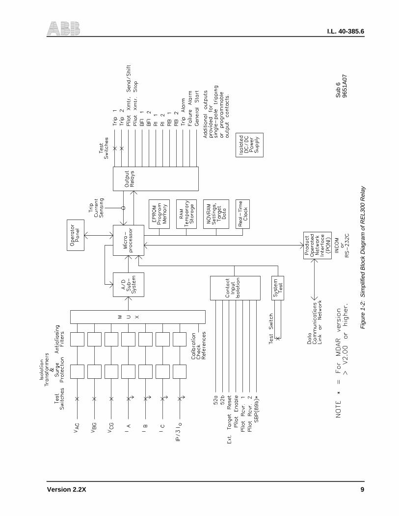
Figure 1-2: Simplified Block Diagram of REL300 Relay. . . . . . . . . . . . . . . . . . . . . . . . . . . . . 9
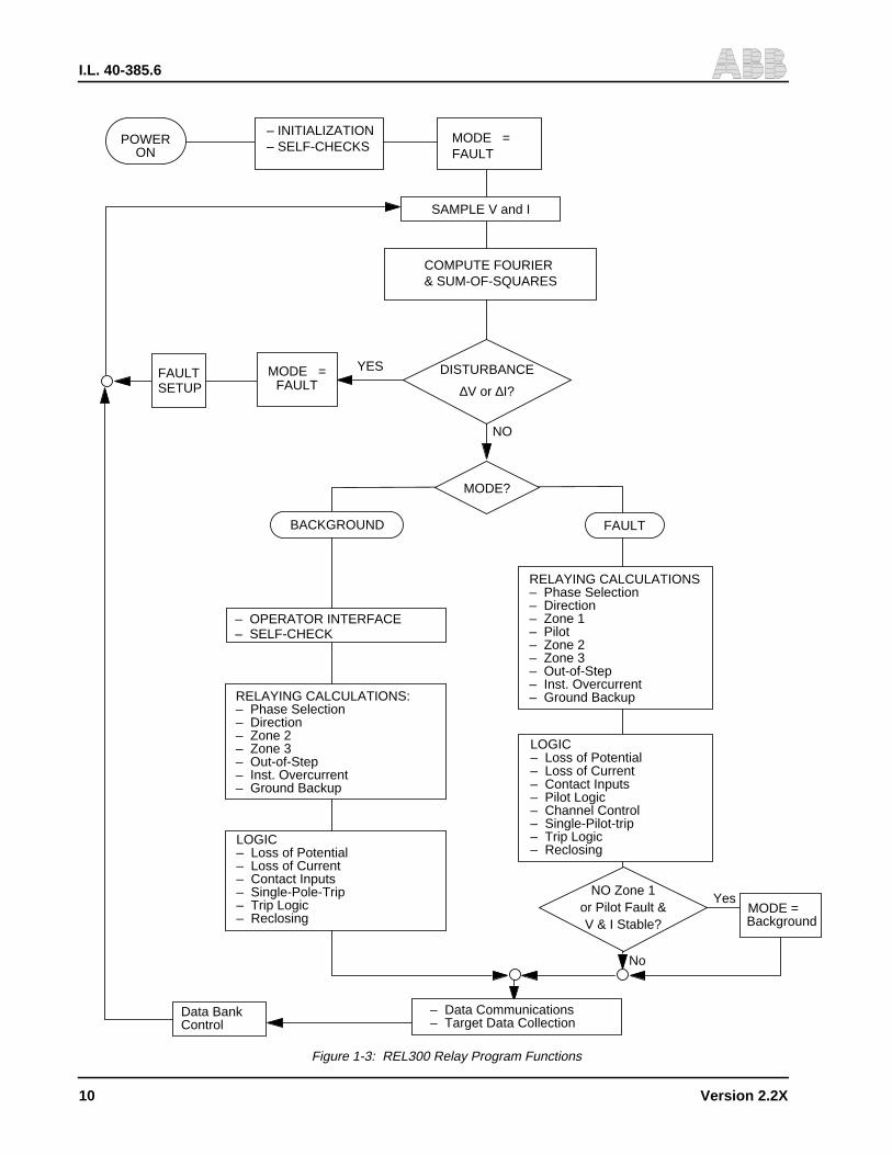
Figure 1-3: REL300 Relay Program Functions . . . . . . . . . . . . . . . . . . . . . . . . . . . . . . . . 10
Figure 2-1: CO-2 Curve Characteristics . . . . . . . . . . . . . . . . . . . . . . . . . . . . . . . . . . . . 16
Figure 2-2: CO-5 Curve Characteristics . . . . . . . . . . . . . . . . . . . . . . . . . . . . . . . . . . . . 17
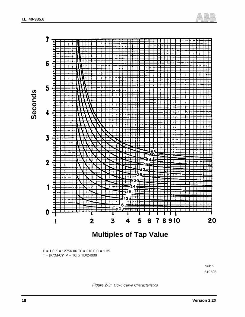
Figure 2-3: CO-6 Curve Characteristics . . . . . . . . . . . . . . . . . . . . . . . . . . . . . . . . . . . . 18
Figure 2-4: CO-7 Curve Characteristics . . . . . . . . . . . . . . . . . . . . . . . . . . . . . . . . . . . . 19
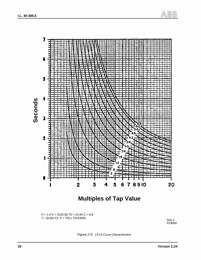
Figure 2-5: CO-8 Curve Characteristics . . . . . . . . . . . . . . . . . . . . . . . . . . . . . . . . . . . . 20
Figure 2-6: CO-9 Curve Characteristics . . . . . . . . . . . . . . . . . . . . . . . . . . . . . . . . . . . . 21
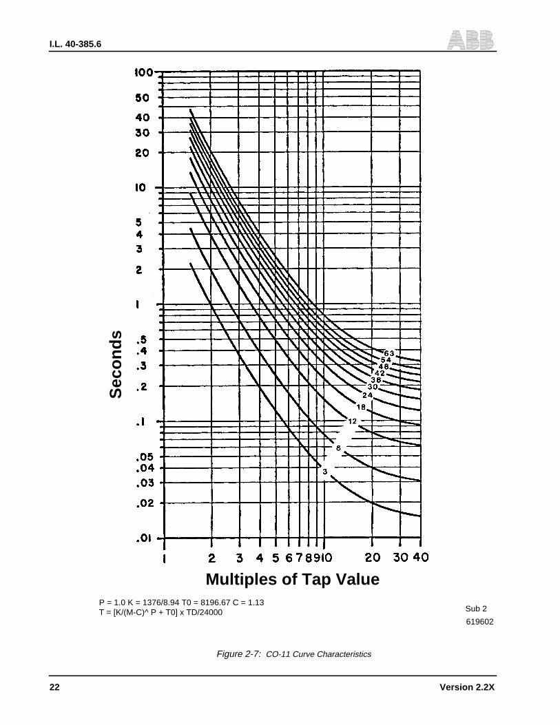
Figure 2-7: CO-11 Curve Characteristics . . . . . . . . . . . . . . . . . . . . . . . . . . . . . . . . . . . 22
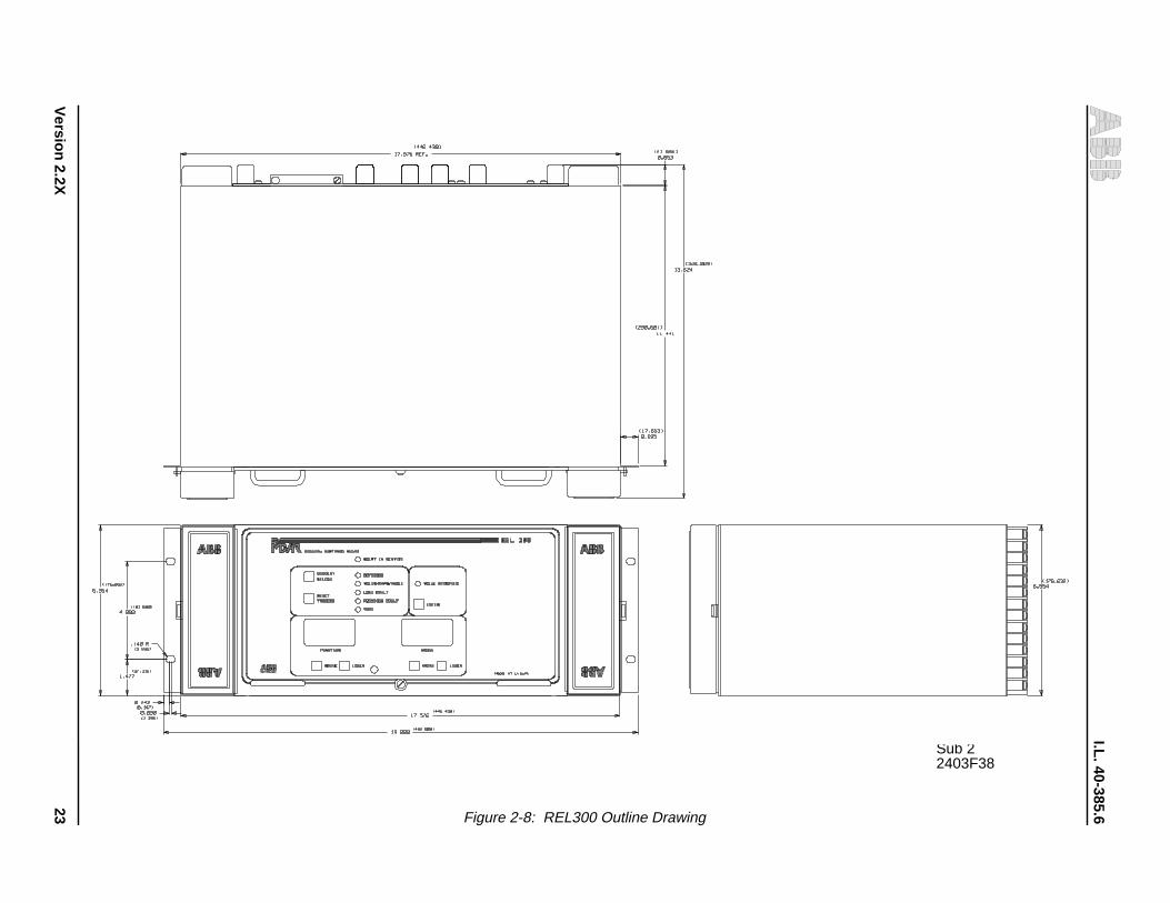
Figure 2-8: REL300 Outline Drawing . . . . . . . . . . . . . . . . . . . . . . . . . . . . . . . . . . . . . 23
Figure 2-9: REL300 Terminal Connections (Rear View with FT-14 Switches) . . . . . . . . . . . . . . . . 24
Figure 3-1: REL300 Characteristics/R-X Diagram . . . . . . . . . . . . . . . . . . . . . . . . . . . . . . 51
Figure 3-2: Mho Characteristic for Phase-to-Ground Faults . . . . . . . . . . . . . . . . . . . . . . . . . 52
Figure 3-3: Mho Characteristics for Three-Phase Faults (No Load Flow). . . . . . . . . . . . . . . . . . . 53
Figure 3-4: Mho Characteristics for Phase-to-Phase and Two Phase-to-Ground Faults (No Load Flow) . . 53
Figure 3-5: REL300 Zone 1 Trip Logic . . . . . . . . . . . . . . . . . . . . . . . . . . . . . . . . . . . . 54
Figure 3-6: REL300 Zone 2 Trip Logic . . . . . . . . . . . . . . . . . . . . . . . . . . . . . . . . . . . . 55
Figure 3-7: REL300 Zone 3 Trip Logic . . . . . . . . . . . . . . . . . . . . . . . . . . . . . . . . . . . . 56
Figure 3-8: REL300 Zone 1 Extension Scheme. . . . . . . . . . . . . . . . . . . . . . . . . . . . . . . . 57
Figure 3-9: Inverse Time Overcurrent Ground Backup Logic . . . . . . . . . . . . . . . . . . . . . . . . . 57
Figure 3-10a: Loss-of-Potential Logic (Version 2.23) . . . . . . . . . . . . . . . . . . . . . . . . . . . . . . 58
Figure 3-11: Loss of Potential Logic (System Diagram) . . . . . . . . . . . . . . . . . . . . . . . . . . . . 60
Figure 3-12: AC Current Monitoring Logic . . . . . . . . . . . . . . . . . . . . . . . . . . . . . . . . . . . 60
Figure 3-13: Overcurrent Supervision . . . . . . . . . . . . . . . . . . . . . . . . . . . . . . . . . . . . . 61
Figure 3-14: Instantaneous Overcurrent Highset Trip Logic . . . . . . . . . . . . . . . . . . . . . . . . . . 61
Figure 3-15a: REL300 Close-Into-Fault Trip (CIFT) and Stub Bus Protection Logic . . . . . . . . . . . . . . 62
Figure 3-15b: Special Application for CIF Logic with LV Time Delay Pickup . . . . . . . . . . . . . . . . . . 62
Figure 3-16: REL300 Unequal-Pole-Closing Load Pickup Trip Logic . . . . . . . . . . . . . . . . . . . . . 63
Figure 3-17: Load Loss Accelerated Trip Logic. . . . . . . . . . . . . . . . . . . . . . . . . . . . . . . . . 64
Figure 3-18a: Out-of-Step Block Logic (Blinder Characteristics). . . . . . . . . . . . . . . . . . . . . . . . . 64
Figure 3-18b: Out-of-Step Block Logic . . . . . . . . . . . . . . . . . . . . . . . . . . . . . . . . . . . . . . 65
Figure 3-19: Reclosing Initiation Logic . . . . . . . . . . . . . . . . . . . . . . . . . . . . . . . . . . . . . 66
xvii
I.L. 40-385.6
Figure 3-20: Single Pole Trip Logic . . . . . . . . . . . . . . . . . . . . . . . . . . . . . . . . . . . . . . . 67
Figure 3-21: Pilot Trip Relay . . . . . . . . . . . . . . . . . . . . . . . . . . . . . . . . . . . . . . . . . . 67
Figure 3-22: POTT/Unblocking Pilot Trip Logic . . . . . . . . . . . . . . . . . . . . . . . . . . . . . . . . . 68
Figure 3-23: Carrier Keying/Receiving Logic in POTT/Unblocking Schemes. . . . . . . . . . . . . . . . . . 68
Figure 3-24: PUTT Keying Logic . . . . . . . . . . . . . . . . . . . . . . . . . . . . . . . . . . . . . . . . 69
Figure 3-25: Blocking System Logic . . . . . . . . . . . . . . . . . . . . . . . . . . . . . . . . . . . . . . 70
Figure 3-26: PLTG Supplemented by FDOG . . . . . . . . . . . . . . . . . . . . . . . . . . . . . . . . . . 71
Figure 3-27: Power Reversed on POTT/Unblocking Schemes . . . . . . . . . . . . . . . . . . . . . . . . . 71
Figure 3-28: Unequal Pole Closing on Fault . . . . . . . . . . . . . . . . . . . . . . . . . . . . . . . . . . 72
Figure 3-29: Additional Logic for POTT/Unblocking Schemes on 3-Terminal Line Application. . . . . . . . . 72
Figure 3-30: Additional Logic for PUTT Scheme on 3-Terminal Line Application. . . . . . . . . . . . . . . . 73
Figure 3-31: Weakfeed Application . . . . . . . . . . . . . . . . . . . . . . . . . . . . . . . . . . . . . . . 74
Figure 3-32: Reversible Zone 3 Phase and Ground (Reverse Block Logic) . . . . . . . . . . . . . . . . . . 74
Figure 3-33: Composite Signal For Programmable Output Contacts . . . . . . . . . . . . . . . . . . . . . . 75
Figure 4-1: REL300 Backplate. . . . . . . . . . . . . . . . . . . . . . . . . . . . . . . . . . . . . . . . . 93
Figure 4-2: REL300 Backplane PC Board Terminals . . . . . . . . . . . . . . . . . . . . . . . . . . . . . 94
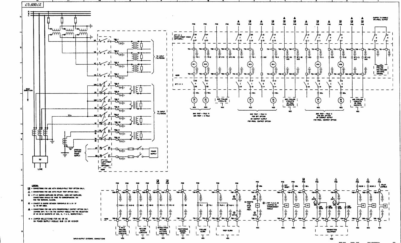
Figure 4-3: REL300 Systems External Connection . . . . . . . . . . . . . . . . . . . . . . . . . . . . . . 95
Figure 6-1 Test Connection for Single-Phase-to-Ground Faults . . . . . . . . . . . . . . . . . . . . . . .141
Figure 6-2 Test Connection for Three-Phase Faults . . . . . . . . . . . . . . . . . . . . . . . . . . . . .142
Figure 6-3 Test Connection for Phase-to-Phase Faults . . . . . . . . . . . . . . . . . . . . . . . . . . .143
Figure 6-4 Test Connection for Dual Polarizing Ground Directional Unit . . . . . . . . . . . . . . . . . . .144
Figure 6-5 REL300 with Out-of-Step Block Optior . . . . . . . . . . . . . . . . . . . . . . . . . . . . . .145
Figure SD-1: REL300 Block Diagram V2.23. . . . . . . . . . . . . . . . . . . . . . . . . . . . . . . . . . .162
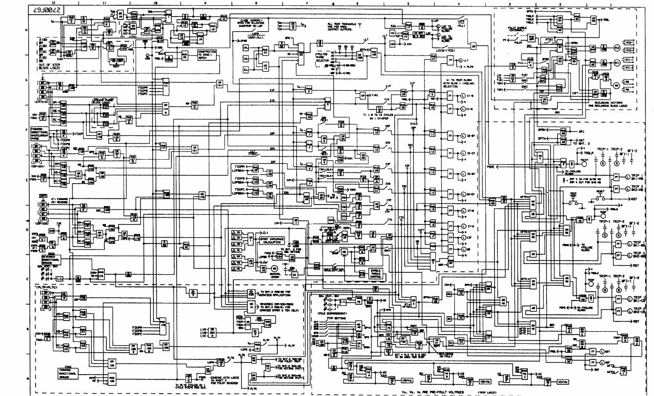
Figure SD-2a: REL300 System Logic Diagram (Sheet 1 of 3) V2.23 . . . . . . . . . . . . . . . . . . . . . .163
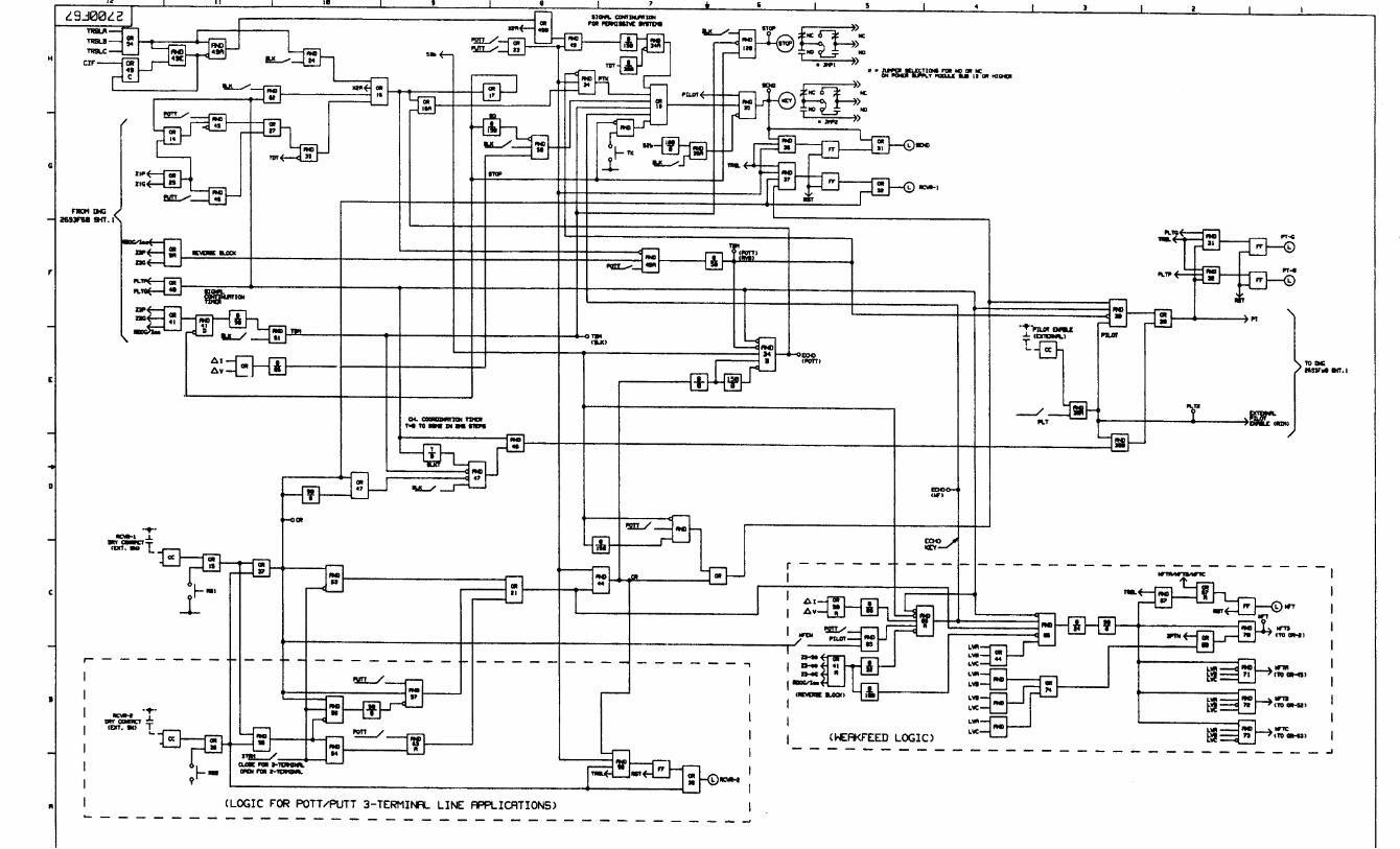
Figure SD-2b: REL300 System Logic Diagram (Sheet 2 of 3) V2.23 . . . . . . . . . . . . . . . . . . . . . .164
Figure SD-2c: REL300 System Logic Diagram (Sheet 3 of 3) V2.23. . . . . . . . . . . . . . . . . . . . . . .165
FIGURE NO
I.L. 40-385.6
xviii
TABLESTABLE NO
TABLE 3-1: REL300 CATALOG NUMBERS. . . . . . . . . . . . . . . . . . . . . . . . . . . . . . . . . . . 76
TABLE 3-2: REL300 ACCESSORIES . . . . . . . . . . . . . . . . . . . . . . . . . . . . . . . . . . . . . . 77
TABLE 3-3: SINGLE-POLE-TRIP OPERATING MODES . . . . . . . . . . . . . . . . . . . . . . . . . . . . 77
TABLE 3-4: REL300 PROGRAMMABLE OUTPUT CONTACTS . . . . . . . . . . . . . . . . . . . . . . . . 78
TABLE 4-1: SETTING DISPLAY (SHEET 1 OF 3). . . . . . . . . . . . . . . . . . . . . . . . . . . . . . . . 96
TABLE 4-1: SETTING DISPLAY (SHEET 2 OF 3). . . . . . . . . . . . . . . . . . . . . . . . . . . . . . . . 97
TABLE 4-1: SETTING DISPLAY (SHEET 3 OF 3). . . . . . . . . . . . . . . . . . . . . . . . . . . . . . . . 98
TABLE 4-2: METERING DISPLAY. . . . . . . . . . . . . . . . . . . . . . . . . . . . . . . . . . . . . . . . 99
TABLE 4-3: TARGET (FAULT DATA) DISPLAY (SHEET 1 OF 2) . . . . . . . . . . . . . . . . . . . . . . . 100
TABLE 4-3: TARGET (FAULT DATA) DISPLAY (SHEET 2 OF 2) . . . . . . . . . . . . . . . . . . . . . . . 101
TABLE 4-4: RECOMMENDED JUMPER POSITIONS (V2.2X) . . . . . . . . . . . . . . . . . . . . . . . . . 102
TABLE 4-5: OUTPUT CONTACT SELECTION . . . . . . . . . . . . . . . . . . . . . . . . . . . . . . . . . 103
TABLE 4-6: COMMUNICATIONS CABLE REQUIREMENTS . . . . . . . . . . . . . . . . . . . . . . . . . . 104
TABLE 4-7: DIP SWITCH SETTING CHART . . . . . . . . . . . . . . . . . . . . . . . . . . . . . . . . . . 104
TABLE 5-1: CURRENT TRANSFORMER SETTINGS . . . . . . . . . . . . . . . . . . . . . . . . . . . . . 117
TABLE 5-2: RECLOSING INITIATION MODE PROGRAMMING . . . . . . . . . . . . . . . . . . . . . . . . 118
TABLE 5-3: TRIP TIME CONSTANTS FOR CURVES . . . . . . . . . . . . . . . . . . . . . . . . . . . . . 118
TABLE 6-1: PRESENT REL300 SETTINGS (PILOT SYSTEM) - V2.2X . . . . . . . . . . . . . . . . . . . . 139
TABLE 6-2: TRIP TIME CONSTANTS FOR CO CURVES . . . . . . . . . . . . . . . . . . . . . . . . . . . 139
TABLE 6-3: FAULT TYPES APPLIED TO REL300 . . . . . . . . . . . . . . . . . . . . . . . . . . . . . . . 140
I.L. 40-385.6
Version 2.2X 1
Section 1. PRODUCT DESCRIPTION
1.1 INTRODUCTION
The REL300 relay assembly is a numerical transmission line protection system, with threezones of distance protection. All measurements and logic are performed by digital means, us-ing a microprocessor. Self-checking and line monitoring techniques are included. REL300 isprimarily recommended for application on non-series compensated lines.
The non-pilot REL300 relay system is standard (see Section 3, page 27); an optional pilotREL300 relay system is also available (in Section 3, page 27).
1.2 REL300 CONSTRUCTION
The standard nomenclature for ABB r elay protection equipment is as follows:
• Cabinet - contains fixed-racks, swing-racks, or open racks
• Rack - contains one or more chassis (e.g., the REL300)
• Chassis - contains several modules (e.g., Microprocessor or Power Supply)
• Module - contains a number of functional circuits (on printed circuit board)
• Circuit - a complete function on a printed circuit board (e.g., analog-to-digital conversion)
• The REL300 relay assembly consists of an outer-chassis and an inner-chassis which slidesinto the outer-chassis. The REL300 conforms to the following dimensions and weight (seealso Section 2. page 13):
• Height 7" (requires 4 rack units; 1.75" each)
• Width 19"
• Depth 13.6"
• Weight 35 Lbs
All of the relay circuitry, with the exception of the input isolation transformers and first-line surgeprotection, are mounted on the inner chassis, to which the front panel is attached. The outerchassis has a Backplate, which is a receptacle for all external connections, including a commu-nication adaptor (see Figure 4-1, page 95). Two FT-14 switches may be included, as options,in the two peripheral areas of the outer chassis. The FT-14 switches permit convenient andsafe disconnection of trip, ac and dc input circuits, and provide for injection of test signals.
The REL300 relay provides the following contact outputs:
• 4 make contacts (2 trip, 2 BFI); 8 additional optional contacts when single pole trip option isused.
• Single pole reclose initiate (2 Form A)
• Three pole reclose initiate (2 Form A)
• Reclose block (2 Form A)
• General Start (1 Form A)
• System failure alarm (1 Form C)
• Trip alarm (1Form C; 1 Form A is available if SBP is not used).
• 8 additional programmable contacts when the Contact module is used.

I.L. 40-385.6
2 Version 2.2X
1.3 REL300 MODULES
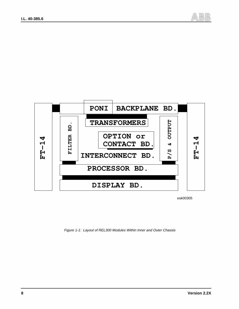
The inner and outer chassis, together, contain 6 standard modules, plus the option module forsingle pole trip applications (see Figure 1-1, page 9). The Backplate is connected to the Back-plane module (outer chassis). The remaining modules are attached to the inner chassis:
• Interconnect module
• Option module or Contact module
• Filter module
• Microprocessor module
• Display module
• Power Supply module
1.3.1 Backplane Module
The Backplane Assembly includes three voltage transformers, four current transformers, twofilter chokes and several surge protection capacitors.
The Backplane Module receives all external connections (with or without the FT-14 switch op-tion), and connects directly to the Interconnect module, thru plug-in connectors (J11, J12, J13)which provide the connection between outer and inner chassis.
The female parts of the connectors are mounted on the Backplane module, which is part of theouter chassis. The male parts of the connectors are mounted on the Interconnect module,which is part of the inner chassis.
The NET or RS-PONI is mounted on the Backplate of the outer chassis and is connected to theBackplane module. For details, see I.L. 40-611 and 40-610 respectively.
1.3.2 Interconnect Module
The Interconnect module becomes the floor of the REL300 inner chassis; it provides electricalconnections from and to all other modules: from the Backplane (at the rear), to the Filter andPower Supply modules (at left and right, respectively), and to the Microprocessor and Displaymodules at the front of the inner chassis.
The Interconnect module receives inputs VAN, VB N
, VCN
, IA, I
B, I
C, IP from the Backplane mod-
ule and feeds them to the Filter module. The IP input is used for zero-sequence dual-polarizingground current measurement; the input is from the power transformer neutral ct. Also, sevenopto-couplers, on the Interconnect module, send the following signals to the Microprocessormodule:
• External Reset - resets the target display.
• 52b - used for close-into-fault (CIF) detection, load loss trip (LLT) and carrier-start and stopcontrol in a pilot system.
• 52a (for single-pole trip option; i.e., for pole disagreement).
• Pilot Enable - should be “ON” for the pilot system option.
• Receiver #1 (for Pilot option) - carrier receiver for two terminal application.
• Receiver #2 (for Pilot option) - second carrier receiver for three-terminal application.
• SBP (89b) for stub bus protection.
I.L. 40-385.6
Version 2.2X 3
1.3.3 Option Module/Contact Module
For single-pole tripping applications, an Option module is added with extra tripping and reedrelays. The Option module plugs into the Interconnect module.
For 3-pole tripping application, an optional Contact module can be plugged into the connectorand provide 8 additional programmable output contacts.
1.3.4 Filter Module
The Filter module band-limits the seven inputs from the Interconnect module: VAN, VBN, VCN,IA, IB, IC, IP. These inputs are fed to the Microprocessor module (analog signal multiplexer).
1.3.5 Microprocessor Module
The Microprocessor module includes the following subsystems:
• Microprocessor - Intel 80C196, a 16-bit microcontroller operating with a 10 MHz clock.
• EPROM - Program memory in separate, easily-replaced EPROM chips.
• PROM - Programmable read-only memory.
• RAM - Volatile read-write memory, for working storage.
• NOVRAM (EEPROM) - Non-volatile memory for storing settings and fault-data targets whenthe REL300 relay is deenergized.
• A/D Converter - The seven inputs from the filter module are analog-multiplexed to a singlesample/hold circuit. The output of the sample/hold is fed to the Analog-to-Digital Converterthrough an auto-ranging circuit which shifts gain by a factor of eight.
• Digital I/O Circuitry - Status inputs from breaker auxiliary contacts (52a and 52b), and Ex-ternal Reset signal are interfaced to the microprocessor via optical isolators (Figure 4-2, page96). The microprocessor executes control outputs using dry contacts. Output relays (Figure4-2) are used for breaker tripping, breaker failure initiation (BFI), reclose initiation (RI), andreclose blocking (RB). General start contact (GS) is provided for starting the external se-quence of events or fault recorders. Trip and relay-failure alarm contacts are included. Reedrelays in the trip circuits sense trip coil current flow and feedback target information to themicroprocessor.
For the option of Contact module, eight additional output contacts are provided and can be pro-grammed from 30 functions shown in Table 3-4, page 79.
NOTE: JMP3 should be “OUT” for normal ABC rotation. Insert a jumper into JMP3 position forACB phase rotation system application.
1.3.6 Display Module
The Display module has two (four-digit) alphanumeric displays for settings, metering fault des-ignation and information. The metering display shows three-phase voltage, current and angle.Fault data, stored in the Microprocessor module, is accessible through the front panel display.Fault data includes: pre-fault phase A voltage, current and angle. It also shows the type of fault,fault voltages, currents, angles and fault location. The Display module is attached to the frontpanel; it can be used to access and store data, and contains 7 LEDs, as follows:
I.L. 40-385.6
4 Version 2.2X
• Relay in Service (ready to use)• Settings (can read or change settings)• Volts/Amps/Angles (can read measuring inputs)• Last Fault (when flashing, indicates new fault information available)• Previous Fault (when last fault LED flashes twice/minute, indicates information for the fault
preceding the last fault)• Value Accepted (when the Settings LED is also “ON”, a new setting value is accepted; when
the Test LED is also “ON”, the output contacts can be tested)• Test (can verify self-check and perform functional test)
The display will be blocked momentarily, every minute, for the purpose of self-check; this willnot affect the relay protection function.
A display saver software is also built in. The REL300 display will be on only for 5 minutes afterturning the dc power on or depressing any one of the front panel push-button or detecting faultson the line.
1.3.7 Power Supply Module
The Power Supply module is available in three ranges:
• 38 - 70 Vdc• 88 - 145 Vdc• 176 - 290 Vdc
Provides isolation from station battery; includes overcurrent and overvoltage protection. Statusmonitoring and loss-of-power indication are accomplished via a failure-alarm relay (on the In-terconnect module). Relay is normally picked up, but the processor deenergizes it when a prob-lem is found. Total power loss also drops-out the relay.
1.3.8 Contact Outputs
1.4 TEST ACCESSORIES
The REL300 may be tested with two devices:
• Inner Chassis Test Fixture.
This device is similar to the outer chassis, and includes a Backplane and Transformer assem-bly.
• Extender Board
This device includes two small pc boards with two ribbon cables. The inner chassis can be test-ed outside of the outer case by means of the Extender Board.
1.5 FAULT DETECTION SOFTWARE
REL300 fault-detection software operates in two modes:
• Background mode• Fault mode

I.L. 40-385.6
Version 2.2X 5
The REL300 relay normally operates in the “Background mode” where it looks for phase cur-rent or phase voltage disturbances. Once a phase disturbance is detected, the relay enters the“Fault mode”. During non-fault operation (in the Background mode), the REL300Microprocessor (U100) used its spare time to check its hardware, service the operator panel,and check for a disturbance in voltage or current which indicates a possible fault. If a distur-bance is seen, the programs switch to the Fault mode, for several power cycles or longer, toperform phase and ground unit checks for each zone and function.
1.5.1 Background Mode
During the background mode, the seven inputs (currents and voltages shown in Figure 1- 2,page 10) are sampled to test for line faults. These currents and voltages are sampled and con-verted into digital quantities and input to the Microprocessor where all signal processing takesplace. (REL300 detects faults by digital computation; not by analog.) The system continuouslytakes 8 samples per cycle. The components of the signals which are power system frequencyare extracted.
The REL300 software which does the sampling has 8 states; these states correspond to thesampling rate (8 samples per cycle). Movement from state to state is controlled by a timer. Thetimer is loaded with a state time at the beginning of the state. The code executed within a stateshould be completed before the timer expires. The software then waits for the timer to time out.
The REL300 relay program functions are included in a flow chart loop (shown in Figure 1- 3,page 11), which the Microprocessor repeats 8 times per power cycle. Most functions are per-formed all of the time, in the background mode, as shown. An important detail (not shown inFigure 1- 3) is that many of the checks are broken into small parcels, so that the whole com-plement of tasks is performed over a one-cycle period (eight passes through the loop). Someof the checks are performed more than once per cycle.
The 60 Hz components are extracted from the samples (from each cycle) and converted to volt-age and current phasor values using a Full Cycle Fourier notch-filter algorithm During the pro-cess the Fourier coefficients and sums are calculated for computing the phase angles,amplitude and RMS values of current and voltage. An anti-aliasing filter is used to filter out highfrequencies. The Fourier algorithm is also used to remove dc and unwanted harmonics.
1.5.2 Fault Mode and Restricted Fault Tests
Upon entry into the fault mode, the sums of the Fourier coefficients and sum of squares fromthe background mode are stored. New sums are obtained by using fault data.
To speed up tripping for severe faults, restricted fault testing is implemented. The last half cycleof background mode input samples and the first half cycle of fault mode input samples are usedto compute the current and voltage vectors and rms values. No dc offset compensation is per-formed fault current is of a large magnitude on a zone 1 high speed trip, therefore, the dc offsetis negligible. High-set instantaneous overcurrent and Zone 1 distance unit tests are executed(see Section 3.2, LINE MEASUREMENT TECHNIQUES on page 27). This will speed up trip-ping by as much as one cycle for high current faults.
Instantaneous overcurrent, inverse time overcurrent protection, and out-of-step blocking arealso conducted during the fault mode and background mode.
I.L. 40-385.6
6 Version 2.2X
For Zone 2 and Zone 3 faults (see Section 3, NON-PILOT SYSTEM on page 27), impedancecomputation and checking will continue throughout the specified time delay. The impedancecalculation will be performed once every cycle, in the fault mode and background mode.
1.5.3 Unique Qualities of REL300
A unique characteristic of the REL300 system is its phase selection principle. It determines thesum of positive and negative sequence currents for each phase by a novel method which ex-cludes the influence of pre-fault load current. From this information, the fault type can be clearlyidentified and the actual distance to the fault can be estimated.
High-resistance ground-fault detection is available in REL300. Sensitive directional pilot trip-ping is achieved through an FDOG timer (FDGT), which is selectable from 0 to 15 cycles orblock, on the Microprocessor module. The pilot distance unit is always active and has the pri-ority for tripping.
Load-loss tripping entails high-speed, essentially simultaneous clearing at both terminals of atransmission line for all fault types except three-phase, without the need of a pilot channel.
Any fault location on the protected circuit will be within the reach of the zone 1 relays at one orboth terminals. This causes direct tripping of the local breaker without the need for any infor-mation from the remote terminal. The remote terminal recognizes the loss of load-current in theunfaulted phase(s) as evidence of tripping of the remote breaker. This, coupled with Zone 2distance or directional overcurrent ground fault recognition at that terminal, allows immediatetripping to take place at that terminal.
1.6 SELF-CHECKING SOFTWARE
REL300 continually monitors its ac input subsystems using multiple A/D converter calibration-check inputs, plus loss-of-potential and loss-of-current monitoring described. Failures of theconverter, or any problem in a single ac channel which unbalances nonfault inputs, triggeralarms. Self-checking software includes the following functions:
a. Digital Front-end A/D Converter Check
b. Program Memory Check Sum
Immediately upon power-up, the relay does a complete ROM (EPROM) checksum of programmemory. Afterwards, the REL300 relay continually computes the program memory checksum.
c. Power Up RAM Check
Immediately upon power-up, the relay does a complete test of the RAM data memory.
d. Nonvolatile RAM Check
All front-panel-entered constants (settings) are stored in nonvolatile RAM in three identicalarrays. These arrays are continuously checked by the program. If all three array entrees dis-agree, a nonvolatile RAM failure is detected, and blocks the tripping action. If only one arraydisagrees with the other two, the failure does not disable the processor and the cause of theproblem will be shown on the display. (See section 4.5.4, Test Mode (Self-Check Routine) onpage 86, for the detailed description.)

I.L. 40-385.6
Version 2.2X 7
e. Output Contact check (see Section 4.5.4, page 86)
f. Opto Input check (see Section 4.5.4, page 86)
1.7 UNIQUE REMOTE COMMUNICATION PROGRAM (RCP)
Special software, RCP is provided for obtaining fault, metering and current settings data as wellas sending data to REL300. RCP can best be described as a user friendly way of using a per-sonal computer (PC) to communicate with ABB protective relays by way of pull-down menus.By coupling a computer with the appropriate communications hardware, it is possible to per-form all relay setting and data interactions that are possible from the man-machine interface.RCP is required to communicate with REL300 via the communication port(s). Refer to RCP in-struction manual, I.L. 40-603, for detailed information. Refer to Section 4.7.2, CommunicationPort Options on page 89, for communication port options.
To obtain the latest RCP communication software, please visit the Power Automation and Pro-tection Division website at:
Visit our website: http://www.abb.com/papdand select Software Download
or call the ABB Power T&D Company Inc., Power Automation and Protection Division bulletinboard system via modem at:
(800) 338-0581or
(954) 755-3250
Using configuration settings 300 - 14,400 bits/second, 8 data bits,1 stop bit, no parity, and fullduplex. Once the connection is established and login is completed. From the TOP menuchoose:L - Library of Files. Then from the Library of Files menu chooseD - Down Load File, file name RCPxxxx.EXE (where xxxx is the most current version numbere.g., 175D or higher).
1.8 POWER SYSTEM ROTATION ABC OR ACB SELECTION
The phase rotation ABC or ACB can be selected by a jumper #3 on the Microprocessor module.The system indicates ABC rotation without jumper #3. With jumper #3 in place, the input phasesequence should be ACB, e.g., phase A leads phase C, C leads B and B leads A, respectively.The rotation is shown on the Metering Mode.
Check jumper #3 before energizing the relay. Jumper #3, should be re-moved for phase sequence rotation ABC.! WARNING
I.L. 40-385.6
8 Version 2.2X
FT
-14
FIL
TE
R B
D.
PONI BACKPLANE BD.
TRANSFORMERS
OPTION or
INTERCONNECT BD.
PROCESSOR BD.
DISPLAY BD.
P/S
& O
UT
PU
T
FT
-14CONTACT BD.
esk00305
Figure 1-1: Layout of REL300 Modules Within Inner and Outer Chassis
I.L. 40-385.6
Version 2.2X 9
Sub
696
51A
07
Fig
ure
1-2:
Sim
plifi
ed B
lock
Dia
gram
of R
EL3
00 R
elay
I.L. 40-385.6
10 Version 2.2X
POWERON
– INITIALIZATION– SELF-CHECKS
MODE =FAULT
SAMPLE V and I
COMPUTE FOURIER& SUM-OF-SQUARES
MODE?
NO
BACKGROUND FAULT
– OPERATOR INTERFACE– SELF-CHECK
RELAYING CALCULATIONS:– Phase Selection– Direction– Zone 2– Zone 3– Out-of-Step– Inst. Overcurrent– Ground Backup
LOGIC– Loss of Potential– Loss of Current– Contact Inputs– Single-Pole-Trip– Trip Logic– Reclosing
RELAYING CALCULATIONS– Phase Selection– Direction– Zone 1– Pilot– Zone 2– Zone 3– Out-of-Step– Inst. Overcurrent– Ground Backup
LOGIC– Loss of Potential– Loss of Current– Contact Inputs– Pilot Logic– Channel Control– Single-Pilot-trip– Trip Logic– Reclosing
NO Zone 1or Pilot Fault &V & I Stable?
Data BankControl
– Data Communications– Target Data Collection
MODE =Background
No
Yes
DISTURBANCE
∆V or ∆I?FAULTSETUP
MODE =FAULT
YES
Figure 1-3: REL300 Relay Program Functions
I.L. 40-385.6
Version 2.2X 11
Section 2. SPECIFICATIONS
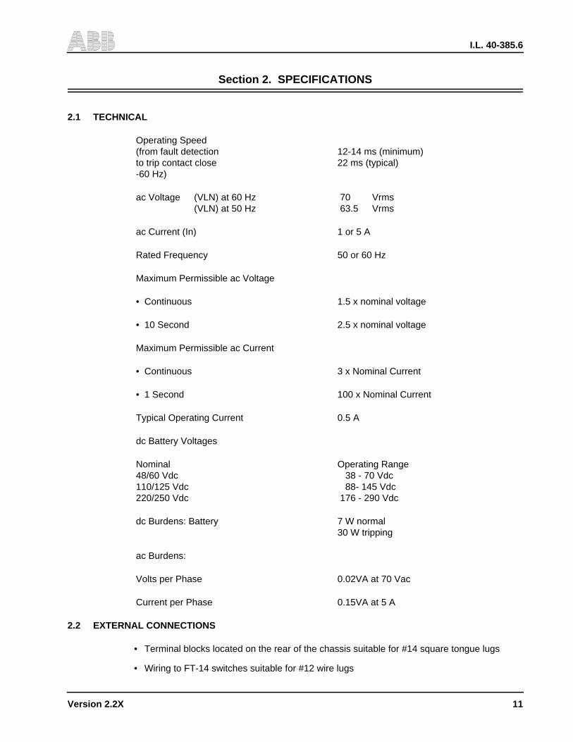
2.1 TECHNICAL
Operating Speed(from fault detection 12-14 ms (minimum)to trip contact close 22 ms (typical)-60 Hz)
ac Voltage (VLN) at 60 Hz 70 Vrms(VLN) at 50 Hz 63.5 Vrms
ac Current (In) 1 or 5 A
Rated Frequency 50 or 60 Hz
Maximum Permissible ac Voltage
• Continuous 1.5 x nominal voltage
• 10 Second 2.5 x nominal voltage
Maximum Permissible ac Current
• Continuous 3 x Nominal Current
• 1 Second 100 x Nominal Current
Typical Operating Current 0.5 A
dc Battery Voltages
Nominal Operating Range48/60 Vdc 38 - 70 Vdc110/125 Vdc 88- 145 Vdc220/250 Vdc 176 - 290 Vdc
dc Burdens: Battery 7 W normal30 W tripping
ac Burdens:
Volts per Phase 0.02VA at 70 Vac
Current per Phase 0.15VA at 5 A
2.2 EXTERNAL CONNECTIONS
• Terminal blocks located on the rear of the chassis suitable for #14 square tongue lugs
• Wiring to FT-14 switches suitable for #12 wire lugs
I.L. 40-385.6
12 Version 2.2X
2.3 CONTACT DATA
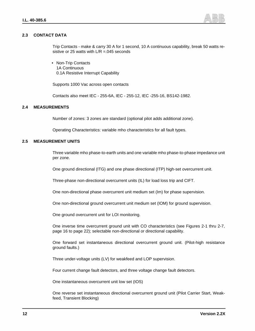
Trip Contacts - make & carry 30 A for 1 second, 10 A continuous capability, break 50 watts re-sistive or 25 watts with L/R =.045 seconds
• Non-Trip Contacts1A Continuous0.1A Resistive Interrupt Capability
Supports 1000 Vac across open contacts
Contacts also meet IEC - 255-6A, IEC - 255-12, IEC -255-16, BS142-1982.
2.4 MEASUREMENTS
Number of zones: 3 zones are standard (optional pilot adds additional zone).
Operating Characteristics: variable mho characteristics for all fault types.
2.5 MEASUREMENT UNITS
Three variable mho phase-to-earth units and one variable mho phase-to-phase impedance unitper zone.
One ground directional (ITG) and one phase directional (ITP) high-set overcurrent unit.
Three-phase non-directional overcurrent units (IL) for load loss trip and CIFT.
One non-directional phase overcurrent unit medium set (Im) for phase supervision.
One non-directional ground overcurrent unit medium set (IOM) for ground supervision.
One ground overcurrent unit for LOI monitoring.
One inverse time overcurrent ground unit with CO characteristics (see Figures 2-1 thru 2-7,page 16 to page 22); selectable non-directional or directional capability.
One forward set instantaneous directional overcurrent ground unit. (Pilot-high resistanceground faults.)
Three under-voltage units (LV) for weakfeed and LOP supervision.
Four current change fault detectors, and three voltage change fault detectors.
One instantaneous overcurrent unit low set (IOS)
One reverse set instantaneous directional overcurrent ground unit (Pilot Carrier Start, Weak-feed, Transient Blocking)
I.L. 40-385.6
Version 2.2X 13
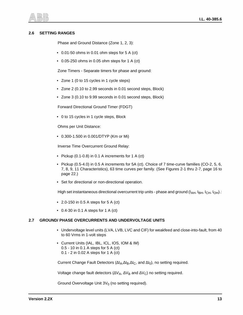
2.6 SETTING RANGES
Phase and Ground Distance (Zone 1, 2, 3):
• 0.01-50 ohms in 0.01 ohm steps for 5 A (ct)
• 0.05-250 ohms in 0.05 ohm steps for 1 A (ct)
Zone Timers - Separate timers for phase and ground:
• Zone 1 (0 to 15 cycles in 1 cycle steps)
• Zone 2 (0.10 to 2.99 seconds in 0.01 second steps, Block)
• Zone 3 (0.10 to 9.99 seconds in 0.01 second steps, Block)
Forward Directional Ground Timer (FDGT)
• 0 to 15 cycles in 1 cycle steps, Block
Ohms per Unit Distance:
• 0.300-1.500 in 0.001/DTYP (Km or Mi)
Inverse Time Overcurrent Ground Relay:
• Pickup (0.1-0.8) in 0.1 A increments for 1 A (ct)
• Pickup (0.5-4.0) in 0.5 A increments for 5A (ct). Choice of 7 time-curve families (CO-2, 5, 6,7, 8, 9, 11 Characteristics), 63 time curves per family. (See Figures 2-1 thru 2-7, page 16 topage 22.)
• Set for directional or non-directional operation.
High set instantaneous directional overcurrent trip units - phase and ground (IAH, IBH, ICH, IOH).:
• 2.0-150 in 0.5 A steps for 5 A (ct)
• 0.4-30 in 0.1 A steps for 1 A (ct)
2.7 GROUND/ PHASE OVERCURRENTS AND UNDERVOLTAGE UNITS
• Undervoltage level units (LVA, LVB, LVC and CIF) for weakfeed and close-into-fault, from 40to 60 Vrms in 1-volt steps
• Current Units (IAL, IBL, ICL, IOS, IOM & IM)0.5 - 10 in 0.1 A steps for 5 A (ct)0.1 - 2 in 0.02 A steps for 1 A (ct)
Current Change Fault Detectors (∆IA,∆IB,∆IC, and ∆I0), no setting required.
Voltage change fault detectors (∆VA, ∆VB and ∆VC) no setting required.
Ground Overvoltage Unit 3V0 (no setting required).

I.L. 40-385.6
14 Version 2.2X
2.8 OPTIONAL SINGLE-POLE-TRIP LOGIC AND OUTPUTS(Without Programmable Contact Option)
• SPT/RI1 on first φGF fault and 3PT on other types of faults
• 3PT/RB if reclosing on a permanent fault
• 3PT/RB if second phase(s) fault during single phasing
• 3PT on a selectable time delay limit if the system fails to reclose (62T)
• TRIP/RI mode selections (TTYP)
SELECT TRIP RI
OFF 3PT NO1PR 3PT RI2 (φG)2PR 3PT RI2 (φG,φφ)3PR 3PT RI2 (φG,φφ,Mφ)SPR SPT (φG) RI1
3PT (Mφ) NOSPR/3PR SPT (φG) RI1
3PT (Mφ) RI2
Legend:
SPT - Single Pole Trip3PT - 3 Pole TripRI - Reclose InitiationRB - Reclose BlockRI2 - 3 Pole Reclose InitiateRI1 - Single Pole Reclose InitiateφG - Single Phase to Ground FaultsMφ - Multi-Phase Faultsφφ - 2-Phase Faults
2.9 OPTIONAL PROGRAMMABLE OUTPUT CONTACTS(Without Single-pole Trip Option)
Eight programmable contacts selected from 30 pre-assigned signals which can be pro-grammed either AND or OR logic together. (Refer to Table 3-4, page 78 for the 30 signals.)
• Four NO heavy duty contacts with FT-switches and 1 timer for pickup and/or dropout delay(0 to 5 sec. in 0.01 sec/step)
• Four Standard contacts with jumper selection for NO or NC outputs and one timer for pickupand/or dropout delay. (0 to 5 sec. in 0.01 sec/step).
2.10 OUT-OF-STEP BLOCK
• OSB Override Timer400-4000 ms in 16 ms steps
• OSB Inner Blinder (RT)1.0-15.0 ohms in 0.1 ohm steps

I.L. 40-385.6
Version 2.2X 15
NOTE: The RT is a standard setting; for load restriction.
• OSB Outer Blinder (RU)3.0-15.0 ohms in 0.1 ohm steps
2.11 SELECTABLE PHASE SEQUENCE ABC OR ACB ROTATION
A jumper #3 on Microprocessor module is used for phase rotation selection.
• ABC system – without jumper #3
• ACB system – with jumper #3 in place
2.12 OPTIONAL COMMUNICATION INTERFACE
• RS-PONI (232C interface) - for single point computer communications
• NET-/PONI (INCOM interface) - for local network communications
2.13 CHASSIS DIMENSIONS AND WEIGHT
Height 7" (177.8mm), 4 Rack Units (See Figure 2-8, page 23)Width 19" (482.6mm)Depth 14" (356mm) including terminal blocksWeight 35 lb. (16Kg net)
2.14 ENVIRONMENTAL DATA
Ambient Temperature Range
• For Operation -20°C to +60°C
• For Storage -40°C to +80°C
Dielectric Test Voltage 2.8 kV, dc, 1 minute (ANSI C37.90.0, IEC 255-5)
Impulse Withstand Level 5 kV peak, 1.2/50 µsec, 0.5 joule (IEC 255-5)
Fast Transient Surge Withstand Capability 4 kV, 5/50 nsec (IEC 801-4); 5kV 10/150 nsec(ANSI C37.90.1).
Oscillatory Surge Withstand Capability 2.5 kV, 1 MHz (ANSI C37.90.1, IEC 255-6)
EMI Volts/Meter Withstand 25 MHz-1GHz, 10V/m Withstand (Proposed ANSI C37.90.2).
2.15 YEAR 2000
For Year 2000 compliance issues, visit our website http://www.abb.com/papd ans view year2000 issues..
I.L. 40-385.6
16 Version 2.2X
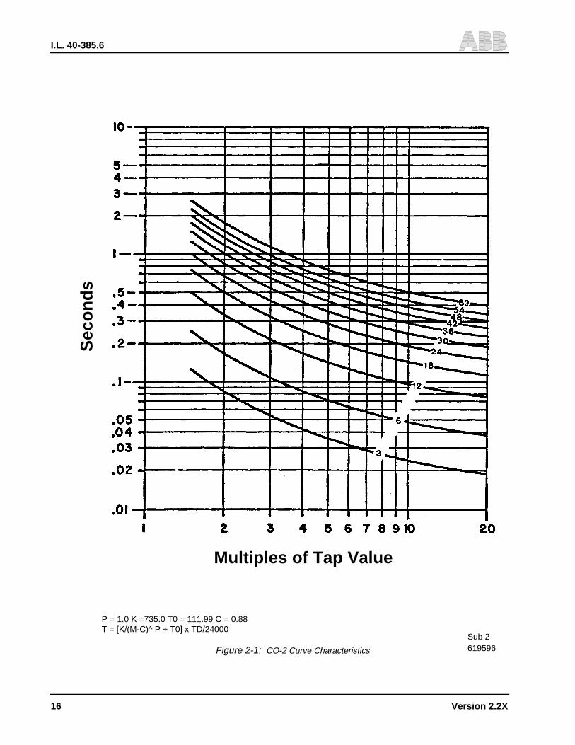
619596Sub 2
P = 1.0 K =735.0 T0 = 111.99 C = 0.88T = [K/(M-C)^ P + T0] x TD/24000
Sec
on
ds
Multiples of Tap Value
Figure 2-1: CO-2 Curve Characteristics
I.L. 40-385.6
Version 2.2X 17
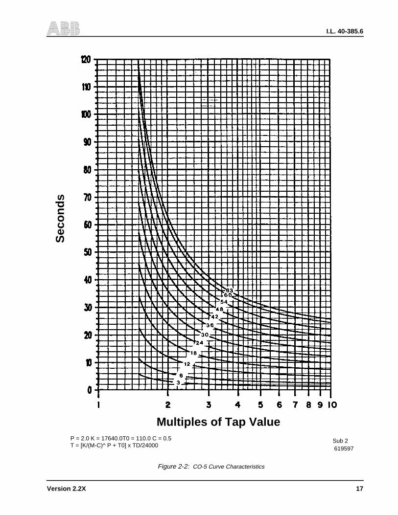
619597Sub 2P = 2.0 K = 17640.0T0 = 110.0 C = 0.5
T = [K/(M-C)^ P + T0] x TD/24000
Sec
onds
Multiples of Tap Value
Figure 2-2: CO-5 Curve Characteristics
I.L. 40-385.6
18 Version 2.2X
619598
Sub 2
P = 1.0 K = 12756.06 T0 = 310.0 C = 1.35T = [K/(M-C)^ P + T0] x TD/24000
Sec
onds
Multiples of Tap Value
Figure 2-3: CO-6 Curve Characteristics

I.L. 40-385.6
Version 2.2X 19
619599Sub 2
P = 1.0 K = 4122.08 T0 = 477.84 C = 1.27T = [K/(M-C)^ P + T0] x TD/24000
Sec
on
ds
Multiples of Tap Value
Figure 2-4: CO-7 Curve Characteristics
I.L. 40-385.6
20 Version 2.2X
619600Sub 2
Multiples of Tap Value
Sec
on
ds
P = 1.0 K = 3120.56 T0 = 24.84 C = 0.8T = [K/(M-C)^ P + T0] x TD/24000
Figure 2-5: CO-8 Curve Characteristics

I.L. 40-385.6
Version 2.2X 21
619601Sub 2
Multiples of Tap Value
P = 1.0 K = 671.01 T0 = 784.52 C = 1.19T = [K/(M-C)^ P + T0] x TD/24000
Sec
on
ds
Figure 2-6: CO-9 Curve Characteristics
I.L. 40-385.6
22 Version 2.2X
619602
Sub 2P = 1.0 K = 1376/8.94 T0 = 8196.67 C = 1.13T = [K/(M-C)^ P + T0] x TD/24000
Sec
on
ds
Multiples of Tap Value
Figure 2-7: CO-11 Curve Characteristics
I.L. 40-385.6
Version 2.2X
23
Sub 22403F38
Figure 2-8: REL300 Outline Drawing
I.L. 40-385.6
24V
ersion 2.2X
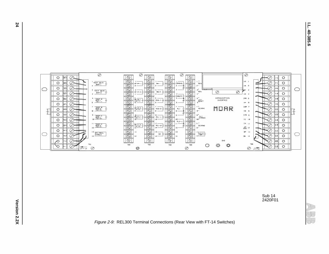
Sub 142420F01
Figure 2-9: REL300 Terminal Connections (Rear View with FT-14 Switches)
I.L. 40-385.6
Version 2.2X 25
Section 3. APPLICATIONS AND ORDERING INFORMATION
! WARNING
Before energizing the relay, check jumper #3 on the Microprocessor module for phasesequence rotation ABC or ACB. Remove jumper #3 for system ABC rotation. Refer toSection 1.8 (page 7) for ACB system. Check jumper #2 which should be in the 1-2 po-sition for three-pole trip or programmable contact outputs. Jumper #2 should be in the2-3 position for single pole trip.
3.1 NON-PILOT SYSTEM
The REL300 non-pilot relay system detects faults in three zones of distance, phase andground. Zones 1 and 2 are forward set; Zone 3 can be set to forward or reverse. There is alsoa separate optional pilot zone (see Section 3.5, page 39). The fault locator can be set to indi-cate fault distance in miles or kilometers.
The R-X Diagram, shown in Figure 3-1, describes the characteristics available with REL300.Zone 1 phase and ground settings are chosen to provide substantial coverage of the protectedline without overreaching the next bus. A setting of 80% of the line impedance is typical. Faultsoccurring within the reach of the Zone 1 measurement cause direct tripping without regard toany action occurring at the remote terminal. Zone 2 settings are chosen to assure that faultsoccurring on the next bus are recognized. Settings are chosen (independent of the Zone 1 set-tings), generally to be 120 to 150% of the line impedance. Any fault occurring on the protectedline will be recognized by this Zone 2 measurement (within the fault resistance and current lim-itations of the relaying system). Zone 2 tripping occurs with time delay (T2) or, where equippedwith pilot provisions, at high speed, subject to the constraints imposed by the pilot channel forthe particular pilot system selected. The Zone 3 measurement is directional, and may be cho-sen to respond to forward or reverse faults. The reverse sensing option is chosen for the block-ing system where the reverse fault carrier start function is required. It is also used in conjunctionwith the T3 trip function, chosen to coordinate with adjacent terminal Zone 2 timing. The for-ward sensing option produces time delayed backup to other devices sensing forward faults.Blinder measurements (B1, B2, B3, B4) are available for out-of-step sensing. The inner blinder(as a standard function) also restricts the trip zone of each of the 3-phase fault measuring units.
3.2 LINE MEASUREMENT TECHNIQUES
Line measurement techniques applied to each zone include:
• Single-Phase-To-Ground fault detection
• 3-Phase fault detection
• Phase-to-Phase fault detection
• Phase-to-Phase-to-Ground fault detection
I.L. 40-385.6
26 Version 2.2X
NOTE: IOM is used to supervise all ground units and IM is used to supervise all phase units,including Zone 1,2,3 and pilot for tripping.
3.2.1 Single-Phase-to-Ground
Single-phase-to-ground fault detection (see Figure 3-2, page 52) is accomplished by 3 quadra-ture polarized phase units (φA, φB, φC). Equations 1 and 2 (below) are for operating and refer-ence quantity, respectively. The unit will produce output when the operating quantity leads thereference quantity.
(1)
Vector (VQ) (2)
where VXG = VAG, VBG, or VCG
IX = IA, IB or IC
Z1L, Z0L = positive and zero sequence lineimpedance in relay ohms
ZCG = Zone reach setting in secondaryohms of Z1L for φGF fault
VQ = quadrature phase voltages, i.e.,VCB, VAC and VBA for φA, φB and φC units, respectively
3.2.2 Three-Phase
Three-phase fault detection (see Figure 3-3) is accomplished by the logic operation of one ofthe three ground units, plus the 3φF output signal from the faulted phase selector unit.
However, for a 3-phase fault condition, the computation of the distance units will be:
VXG - IXZCP (3)
and (VQ) (4)
where VXG = VAG, VBG, or VCG
IX = IA, IB or IC
ZCP = Zone reach setting (PLTP, Z1PZ2P, and Z3P) in secondary ohms of Z1L for multi-phase faults
VXG I X kOI O+[ ]ZCG–
k0
ZoLZ1L–
Z1L----------------------- ZR GANG PANG–( )∠ 1–= =
I 013--- I A I B I C+ +( )=

I.L. 40-385.6
Version 2.2X 27
VQ = Quadrature phase voltages, i.e.,VCB, VAC and VBA for φA, φB and φ C units, respectively
If the REL300 detects that all three voltages are less than 1 volt, the pre-fault voltages (memoryaction) are used as reference for Zone 1 tripping. For Zone 2 and Zone 3, the memory actionis in effect if all three voltages are less than 7 volts.
3.2.3 Phase-to-Phase
The phase-to-phase unit (see Figure 3-4) responds to all phase-to-phase faults, phase-to-phase-to-ground faults, and some single-phase-to-ground faults. Equations (5 and 6) are foroperating and reference quantity, respectively. They will produce output when the operatingquantity leads the reference quantity.
(VAB - IABZCP) (5)
(VCB - ICBZCP) (6)
3.3 MEASUREMENT ZONES
REL300 performs line measurement within 3 zones of the transmission line (Zone 1, Zone 2,Zone 3), and one optional pilot zone. When the REL300 functional display “STYP” is set at“3ZNP”, it will perform the 3-zone non-pilot function.
When the REL300 trips, the trip contacts will be sealed-in as long as the trip coil current flowexists. The trip contacts can be delayed dropout (by 50 ms) after the trip current is removed,providing a jumper (JMP4) on the Microprocessor module is connected.
3.3.1 Zone 1 Trip
For Zone 1 phase faults, the Z1P unit will identify the fault and operate. The 3φ fault logic issupervised by the load restriction logic via AND131C and AND 131 (Figure 3-18a) and is alsosupervised by the selectable OSB, as shown in Figure 3-5, page 54. Outputs of Z1P and IMsatisfy AND-2 and provides a high-speed trip (HST) signal from OR-2 to operate the trip outputtelephone relay. The trip circuit is monitored by a seal-in reed relay (S), which is in-series witheach trip contact in the tripping circuits. The “S” relay will pick up if the trip current is higher than0.5 Amp. The operation of the “S” contact will turn-on the breaker trip indicators (with memory),and feeds back to OR-4 to hold the trip relay in operation until the breaker trips and 52a contactopens (not shown in Figure 3-5). The TRSL signal plus the output signal from AND-2 turns onthe Zone 1 phase trip indicator (Z1P). The breaker trip and Zone 1 phase trip indicators arememorized. They can be reset by external RESET voltage or through remote communication.By pushing the RESET push-button, the flashing LED will be reset, but the fault information willstill remain in memory.
NOTE: The operating time of the Trip relay is 2 ms and the BFI relay is between 10 and 15 ms.The difference of the pickup times should be compensated in the breaker failurescheme.
The Z1P 3φ trip logic AND-131 is supervised by both the conventional OSB and the FDOPA &FDOPB & FDOPC, for more security on some special power system applications. (Refer to

I.L. 40-385.6
28 Version 2.2X
section 3.4.12 for detailed FDOP unit.) ZIP logic AND-2 is also supervised by the IM setting,the medium set phase overcurrent unit.
Similar operations exist for Zone 1 single-phase-to-ground faults. The Z1G unit sees the faultand operates; the IOM and FDOG units also operate, satisfying AND-3. Tripping occurs viaOR-2 with Zone 1 ground trip indication Z1G. Logic AND-3 is also supervised by the signal ofRDOG (reverse directional overcurrent ground) for security purposes.
The Z1G unit is also supervised by the signal of unequal-pole-closing and RDOG.
A two-out-of-three “leading phase blocking” logic is included for solving the overreach problemof the single-phase ground distance units, which may respond to a φφG fault.
The high-speed trip (HST) signal also is connected to the reclosing initiation logic.
Either or both Zone 1 phase and Zone 1 ground function(s) can be disabled by setting the Z1Pand/or Z1G to the “OUT” position. Zone 1 trip can be delayed by setting T1 = 0 to 15 cycles.The delay time is for a non-pilot 3PT backup, with another system operating in SPT mode.
3.3.2 Zone 2 Trip
For Zone 2 phase faults, the Z2P unit will see the faults plus the output of IM and will operatethe Zone 2 phase timer (T2P). AND-4 output plus the T2P timer output satisfy AND-18, asshown in Figure 3-6. The AND-18 output provides time delay trip signal TDT via OR-3. SignalTDT picks up OR-4 (Figure 3-5, page 54) and operates the trip relay. The tripping and targetingare similar as described in Zone 1 trip except for Zone 2 phase time delay trip indicator (Z2P).
Similar operation occurs for Zone 2 single-phase-to-ground faults. The Z2G unit sees the faultand operates. This, plus the operation of the IOM, FDOG and T2G satisfy AND-19, and providethe TDT signal via OR-3 with Zone 2 ground time delay trip indicator (Z2G).
The single-phase ground distance units may respond to a φφG fault. The output of the Z2G unitplus the operation of the φφ selection will trip the Z2P via OR-157, T2P and AND-18. Leadingphase blocking is unnecessary for an overreach Zone device.
The TDT signal can be connected to the reclosing block logic. The settings for Zone 2 timers(phase and ground units) are independent, as follows:
• T2P (Zone 2 phase)
• T2G (Zone 2 ground)
The range of the timers is as follows:
• T2P and T2G (0.1 to 2.99 seconds or Block)
Either or both Zone 2 phase and Zone 2 ground function(s) can be disabled by setting Z2P and/or Z2G to the BLK position.
3.3.3 Zone 3 Trip
For Zone 3 phase faults, the Z3P (forward or reverse looking, depending on the Z3FR setting)unit will identify the faults, plus the IM output will operate the Zone 3 phase timer T3P. AND-6
I.L. 40-385.6
Version 2.2X 29
output plus the T3P timer output satisfy AND-20 as shown in Figure 3-7. The AND-20 outputprovides time delay trip signal (TDT) via OR-3. Signal TDT picks up OR-4 (Figure 3-5, page54) and operates the trip relay. The tripping and targeting are similar to Zone 1 trip, except forthe Zone 3 phase time delay trip indicator (Z3P).
For Zone 3 single-phase-to-ground faults, Z3G identifies the fault and operates. This, plus theoperation of the IOM, satisfies AND-7; the TDT signal then trips via OR-3 with Zone 3 groundtime delay trip indicator Z3G. The TDT signal can be connected to the reclosing block logic.For security, the Z3G unit is also supervised by the signal of FDOG when it is set for forwardlooking (or by the signal of RDOG when it is set for reverse looking) via logic OR-171B, AND-171C or AND 171D (as shown in Figure 3-7, page 56).
A similar operation for φφG faults (shown in Zone 2), is applied to Zone 3, through OR-170, T3Pand AND-20 gates.
The settings for Zone 3 timers (phase and ground units) are independent, as follows:
• T3P (Zone 3 phase)
• T3G (Zone 3 ground)
The range of the timers is as follows:
• T3P and T3G (0.1 to 9.99 seconds or Block)
Either or both Zone 3 phase and Zone 3 ground function(s) can be disabled by setting Z3P and/or Z3G to the BLK position.
3.3.4 Zone 1 Extension
This scheme provides a higher speed operation on end zone faults without the application ofpilot channel.
If the REL300 functional display “STYP” is set on Z1E position, the Z1P/Z1G unit will providetwo outputs: one is overreach which is set at 1.25 x Z1 reach by the microprocessor, and oneis the normal Z1 reach. A single shot instantaneous reclosing device should be used when ap-plying this scheme. The targets Z1P/Z1G will indicate either Z1 trip and/or Z1E trip operations.The other functions (e.g., Z2T, Z3T, ac trouble monitoring, overcurrent supervision, IT, CIF, un-equal-pole closing load pickup control, load-loss acceleration trip, etc.) would remain the sameas in the basic scheme (3ZNP).
For a remote internal fault (refer to Figure 3-8, page 57), either Z1P or Z1G will see the faultsince they are set to overreach. High speed trip will be performed via the normal Z1T path (Fig-ure 3-5, page 54), i.e., AND-2 (or AND-3),OR-2. HST signal operates the instantaneous re-closing scheme. The breaker recloses and stays closed if the fault is automatically cleared.
Target Z1P and/or Z1G will be displayed. Once the breaker trip circuit carries current, it oper-ates the logic OR-5 (not shown), produces output signal TRSL, and satisfies logic AND-26 for5000 ms (Figure 3-8). The output signal of AND-26 will trigger the Z1P/Z1G reach circuit, con-stricting their reaches back to the normal Zone 1 for 5000 ms. During the reach constrictingperiods, if the breaker is reclosed on a Zone 1 permanent fault, it will retrip again. If the breakeris reclosed on an end-zone permanent fault, the normal Z2T will take place.

I.L. 40-385.6
30 Version 2.2X
For a remote external fault, either Z1P or Z1G will see the fault since they are set to overreach.High speed trip will be performed. HST signal operates the instantaneous reclosing scheme.The breaker recloses and stays closed if the fault has been isolated by the adjacent line break-er. However, if the adjacent line breaker fails to trip, the normal remote back up will take place.
NOTE: The reaches of Z1E are based on the Zone 1 settings multiplied by a factor of 1.25(i.e., 1.25 x Z1P and 1.25 x Z1G).
3.4 REL300 NON-PILOT FEATURES
The following features are standard with the Non-Pilot REL300:
3.4.1 3-Zone Distance Phase and Ground Relay with Reversible Zone 3 Phase and Ground
There are four impedance units per zone: one phase-to-phase unit and three phase-to-groundunits. Zone 3 can be set to forward or reverse for carrier keying or back-up tripping. For a pilotsystem, Z3FR has to be set to reverse (REV) for correct application.
3.4.2 Directional or Non-Directional Inverse Time Overcurrent Ground Backup Unit
The overcurrent ground backup (GB) unit is to supplement the distance ground protection onhigh resistance ground faults. It provides an inverse time characteristic which is similar to theconventional CO characteristics (see Figure 2-1 through 2-7). The time curves can be selectedby the GBCV Setting. The time dial is set by the “GTC” value. The unit can be selected as di-rectional by using the “GDIR” (YES) setting and the pickup value by GBPU. The directional GBfunction uses the torque control approach, as indicated in Figure 3-9. The GB function can bedisabled by setting the GBCV to the OUT position.
The directional unit is determined by the setting of “DIRU” which can be set to zero sequencevoltage (ZSEQ), dual (DUAL, zero sequence voltage and/or zero sequence current) or negativesequence (NSEQ, negative sequence voltage and negative sequence current) for polarization(see 3.4.11, Selectable Ground Directional Unit, ZSEQ / NSEQ / DUAL).
3.4.3 Loss of Potential Supervision (LOP)
The ac voltage monitoring circuit is called loss-of-potential circuit. In order to prevent undesir-able tripping due to the distance unit(s) pickup on loss-of-potential, the following logic is used:
• (VAN or VBN or VCN <7Vac) or (3Vo>7Vac) and not ∆I or not (3IO>IOS)
This means that the LOPB will be set if any one of the voltages is below 7Vac (without ∆I), orif the system detects 3Vo without 3Io (or 3IO < IOS) as shown in Figure 3-10a. The (loss-of-potential condition satisfies AND-1; output signal of AND-1 starts the 8/0 and 0/500 ms timers.The timer output will satisfy AND-1C if there is no output from AND-1B. Output signal of AND-1C will block all the distance unit (Z) tripping paths via AND-2, AND-3, AND-4, AND-5, AND-6,AND-172 (also blocks AND-191 and AND-187 for Pilot Systems), if LOPB is set at YES. Al-though all distance units are blocked for tripping, the ground backup (GB) and high-set over-current units (ITP and ITG) are operative and converted to non-directional automatically. TheLOPB blocking function can be disabled by setting the LOPB functional display at NO position.The output of the LOP timer will de-energize the alarm 1 (AL1) relay and cause the failure

I.L. 40-385.6
Version 2.2X 31
alarm. If the LOPB is set at “ALL” and LOP condition exists, the relay will block all types of tripand turns off the “IN SERVICE” LED.
When applying the LOPB to DIST, it is the intent to block all distance units from tripping, shouldLOP condition exist. However, under a special system condition (see Figure 3-11), both circuitsare energized without load current; with no source at terminal B, fault at F where F is near ter-minal A, Zone 2 relay at terminal B will be blocked by LOP, and may fail to trip. This is becausethe relay at B sees no current, and a low voltage condition exists before circuit breaker A opens.Another special system condition involves two parallel lines with two symmetrical sources atboth ends. For an evolving flashover fault, at a point equidistant from both terminals, theconventional LOPB logic will block trip, because the first external fault generates “3V0 and not3I0“on the protected line. Logic AND-1A, 1B, -1C, and -1E 150/0, 3500/200 ms timers circuit,in Figure 3-10a, are to solve these problems. This logic unblocks the LOPB circuit and providesa 3500 ms trip window for the distance units to trip if the fault current is detected within 150 msafter LOP has been set up. This logic has no effect on the conditions:
• if ∆I signal occurs ahead of LOP, or
• if LOP and ∆I signals occur simultaneously
NOTE: The loss of potential logic for firmware versions 2.23, 2.22, 2.21 and 2.20 are shown inFigures 3-10a through 3-10d respectively.
The LOPB has three setting values as follows:
a) NO – No trip block on LOP condition.
b) DIST – Block the distance units. Converts the high set (ITP & ITG) and ground backup (GB)to non-directional automatically for the setting of DIRU = ZSEQ or NSEQ if LOP conditionoccurs. For the setting of DIRU = DUAL with Ip > 1.0 ampere, the ITG and GB maintaintheir directionality depending on the 3I0 and Ip.
c) ALL – Block all types of trip and turn off the “IN SERVICE” LED.
3.4.4 Loss of Current Monitoring (LOI)
The ac current monitoring circuit uses I0M (and not Vo) as criterion, as shown in Figure 3-12.Under ct short circuit or open circuit condition, I0M (and not Vo) satisfies AND-23; the outputsignal of AND-23 starts the 10/0.5 seconds timer. (Version 2.20 timer is 0.5/0.5 seconds.) Thetimer output turns “ON” the non-memory LOI indicator, which is shown in the Metering mode,and drops out the AL1 relay (Failure Alarm). If the LOI condition exists and LOIB is set at YES,the trip will be blocked after the 10 seconds.
3.4.5 Overcurrent Supervision
For REL300, as shown in Figure 3-13, the distance units do not require overcurrent supervi-sion; because the relay normally operates in a background mode, they will not start the Zone1 and pilot impedance computation until a phase current or a phase voltage disturbance is de-tected. This approach can minimize the load problem when setting the phase overcurrent units.However, in order to meet the traditional practice, a medium set phase overcurrent unit IM (IAMor IBM or ICM) has been added to REL300 version 2.20 to supervise Z1P/Z2P/Z3P/PLTP tripfunctions, as shown in Figure 3-13. (Note older versions do not have this unit).
I.L. 40-385.6
32 Version 2.2X
NOTE: This unit should not be set to limit the Zone 3 reach, and traditionally should be setabove the load current.
For coordination purposes the ground trip units (Z1G, Z2G, Z3G, PLTG, and FDOG) are super-vised by the medium set ground overcurrent unit (IOM). The IOS setting and RDOG are usedfor carrier send in a Pilot Blocking system.
3.4.6 Instantaneous Forward Directional Overcurrent Trip/Highset Trip Logic
The instantaneous overcurrent units (IAH, IBH, ICH and IOH) are normally set forward directionaland high to detect those faults which occur in the Zone 1 area, therefore, their tripping will occurvia OR-2 for HST, as shown in Figure 3-14 (page 61). These high set trip functions can be dis-abled by setting the ITP (phase) and/or ITG (ground) to the OUT position. The directional unit(ITP and ITG) will be automatically converted to non-directional protection for the setting ofDIRU = ZSEQ or NSEQ if the LOP condition occurs and the setting of LOPB = DIST. For thesetting of DIRU = DUAL with Ip > 1.0 ampere, the ITG and GB maintain their directionality de-pending on the 3I0 and Ip. For IP <1 ampere, the directionality is determined by the voltagepolarization (3I0 & 3V0).
In order to avoid a false trip during the clearing of a reverse fault, an ITG transient block logicis added. The ITG trip will be delayed for 2 cycles if a forward fault is immediately after a reversefault. This function was added in Version 2.23 and is not in previous versions.
3.4.7 Close-Into-Fault Trip (CIFT) and Stub-Bus Protection (SBP) Logic
Close-Into-Fault and Stub-Bus- protection functions supplement the distance unit operation forinstallations where line-side potential sources are used for the distance relaying. The logic forboth functions is combined as shown in Figure 3-15a (page 62), and is under the control of asingle setting, CIF. In a change from earlier firmware versions, a modified CIFT logic employinga 200/0 millisecond delay timer on the low voltage sensing, can be selected instead of the stan-dard CIFT logic. This application is special in nature, and will be discussed later.
The CIF setting has six values, as follows:
VALUE MEANING
OUT No CIFT or SBP selectedCF Standard CIFT, without timer; No SBPCFT Modified CIFT, with timer; No SBPSTUB SBP logic; No CIFTSCF SBP plus standard CIFTSCFT SBP plus modified CIFT
The CIFT logic employs low voltage sensing functions LVA, LVB, and LVC, which deliver a logicone when the particular phase-ground voltage is below the LV setting, adjustable from 40 to 60volts in one volt increments. Current sensors are also employed, IAL, IBL, and ICL, which delivera logic one if the particular phase current is above the IL setting. Additional current sensing of3I0 greater than the IOM setting is also employed. In the standard logic, for 180 msec after thebreaker is closed (52b opens), simultaneous low voltage and current sensing for 16 msec, im-plying a closure into a fault, produces a CIF trip via OR-22B and OR-3, and reclose blocking(RB). A CIF target will appear on the relay fault record and display.
I.L. 40-385.6
Version 2.2X 33
Stub-Bus protection employs the 89b switch from an open line disconnect, in conjunction withthe CIFT current sensing functions, to high-speed trip on overcurrent only, for faults on the stubbetween the current transformers and open disconnect. This is to compensate for the lack ofthe potential source, connected on the line side of the disconnect. Operation is independent ofthe operation of the breaker(s) and the line voltage condition. Tripping, reclose blocking andtargeting are the same as for CIFT.
The modified CIFT logic is employed for the special application shown in Figure 3-15b (page62). Two relays, looking in opposite directions, control a single breaker and share a common52b input and a common set of voltage transformers, located on one side of the breaker. Eachrelay trips the main breaker and the load breaker on the power transformer secondary, for faultson the line section being protected. The standard CIFT logic was found to produce false trippingof one of the load breakers upon reclosing after a successful initial trip, if the fault still persisted.This was due to “arming” of the CIFT logic by the common 52b, in the relay which did not tripfor the initial fault.
The 200/0 msec timer delays the sensing of low voltage and momentarily disables the CIFTfunction during the reclose situation. This timer was selected to be greater than the 180 msecreset time of the 52b, but less than the minimum reclose dead time. For this logic to work prop-erly, the following application rules apply:
1) For the relay with bus-side potential, that is cts and vts on the same side of the breaker (Re-lay 1), set CIF to OUT. With bus-side potential, CIF logic is not needed and may misoperatefor some situations if enabled.
2) For the relay with line-side potential, that is cts and vts on opposite sides of the breaker(Relay 2), set CIF to CFT. Also be sure that the minimum reclose dead time is greater than200 msec. Otherwise, a delayed CIF trip, or possibly no CIF trip, will occur when reclosinginto a forward fault.
3) Set LOPB to “DIST” or “NO”. For the setting of LOPB = “ALL”, the relay may not trip underthe reclose-on-fault condition because the LOPB may be set and block any type of tripping.
Standard CIFT logic, without the timer, should be selected for all applications other than thistwo-relay-one-breaker scheme.
3.4.8 Unequal-Pole-Closing Load Pickup Logic
The ground units may pick up on a condition of load pickup with unequal breaker pole closing.The high speed ground units (Z1G, and FDOG) s hould be supervised under this condition. Thiscan be achieved (as shown in Figure 3-16, page 63) by inserting a 0/50 ms timer (controlled bythe 52b signal) to supervise the Z1G trip AND-3 (Figure 3-5, page 54) and FDOG/IOM trip AND-188 (Figure 3-21, page 67 and 3-26, page 71). It should be noted that the 50 ms time delay willhave no effect on a normal fault clearing.
Pilot distance ground PLTG unit is not required to have this supervision, because its tripping issupervised by the pilot logic.
On internal ground faults, if the mechanical actuator of the circuit breaker operates but the arcdoes not extinguish (e.g., due to low gas pressure), the closing action of the 52b contact, con-nected to REL300, will reset the Z1G trip path AND-3, and ultimately, the BFI contact. This mayintroduce interruption to the BF scheme if BFI logic does not provide seal-in circuit. The AND-3C logic in Figure 3-16 (page 63) will solve this problem.
I.L. 40-385.6
34 Version 2.2X
3.4.9 Selectable Loss-of-Load Accelerated Trip Logic (LLT)
NOTE: The LLT function need not be set for normal operation of the relay. While it can providefaster tripping for end-zone faults, it may not be usable in all situations. It should beapplied with caution, based on thorough knowledge of the system characteristicswhere the relay is applied. It is definitely not applicable where maximum tapped loadmay exceed minimum through-load in the protected line.
The load-loss speedup Zone 2 trip logic senses remote 3-pole clearing on all faults except 3φFto complement or substitute for the action of the pilot channel, to speed up trip at the slow ter-minal. Logic includes AND-24, AND-25, OR-13, 0/32, and 10/0 ms timers (as shown in Figure3-17, page 64). Under normal system conditions, 3-phase load currents are balanced, the lowset overcurrent units (IAL, IBL, ICL satisfy both AND-24 and OR-13). On remote internal faults,Z2P or Z2G picks-up and satisfies the third input to AND-25 via OR-6. However, the signal fromAND-24 is negated to AND-25, therefore, AND-25 should have no output until the remote end3-pole trips. At this time, the local end current will lose one or two phases, depending on thetype of fault (except for the 3-phase fault). The AND-24 output signal changes from “1” to “0”and satisfies AND-25. After 10 ms, this output by-passes the T2 timer, and provides speedupZone 2 trip. The (10/0 ms) time delay is for coordination on external faults with unequal poleclearing. The 0/32 ms timer is needed for security on external faults without load current con-dition. Target LLT will turn on after a LLT trip. The LLT function is selected by setting “YES,FDOG, NO”, where YES = LLT with Z2 supervision; FDOG = LLT with both Z2 and (FDOG/IOM) supervision; the NO = LLT function is not used.
LLT is not recommended for three-terminal lines due to difficulty in determining proper settings(IL) and complicated infeed from the third terminal.
3.4.10 Current or Voltage Change Fault Detector ( ∆I , ∆V) and GS
The REL300 relay normally operates in the Background mode, where it experiences phase cur-rent or voltage disturbances. During background mode, the four input currents (IA, IB, IC and IP)and the three voltages (VA, VB, VC) are sampled at a rate of 8 per cycle to test a line fault. Whena phase disturbance (∆I or ∆V) is detected, the relay enters a fault mode for several cycles orlonger, to perform phase and ground unit distance computation for each goal. The criteria fordetermining a disturbance in the REL300 design are as follows:
1) Each phase ∆I :if [IKn - I(K-1)n] > 1.0 amp.And [IKn - I(K-1)n] / I(K-1)n x 100% > 12.5%
2) Each phase ∆V:if [VKn - V(K-1)n] > 7.0 voltsand [VKn - V(K-1)n] / V(K-1)n x 100% >12.5%
Where n = 0,1, 2, 3, 4, 5, 6, 7 andK = number of cycles
For every voltage or current disturbance, the General Start (GS) relay will pick up for 3 cyclesfor starting external (fault) recorder.
I.L. 40-385.6
Version 2.2X 35
3.4.11 Selectable Ground Directional Unit (ZSEQ/NSEQ/DUAL)
The ground directional unit (DIRU) contains three selections (ZSEQ, NSEQ and DUAL), whichdetermine the operation of the forward directional overcurrent ground (FDOG) and reversed di-rectional (RDOG). If the ZSEQ is selected, both FDOG and RDOG units will be operated as azero-sequence voltage polarizing directional element. Forward direction is identified by the an-gle, if 3I0 leads 3V0, between 30° and 210°. The sensitivity of this element is 3I0 > 0.5A and3V0 >1.0 Vac. (Version 2.20 has 3V0 >3.0 Vac.) If NSEQ is selected, both FDOG and RDOGwill be operated by negative sequence quantities. The maximum sensitivity for the forward di-rectional unit is when I2 leads V2 by 98°, with V2 ≥1.0 Vac and 3I2 ≥ 0.5A.
If DUAL is selected, the FDOG and RDOG will be determined by current polarizing directionalelement (IP) if the input current Ip is greater than 1 amp. The Ip current is from a separate po-larizing source such as a power transformer neutral (ct). The maximum torque angle between3I0 and IP equals zero degrees, i.e., the forward direction is identified when 3I0 leads IP by 0°to 90° or lags by 0° to 90°. The sensitivity of this element is 3I0 > 0.5 and IP > 1.0 ampere. If Ipis less than 1 ampere, the FDOG will be determined by the zero sequence voltage polarizingelement as the setting of ZSEQ.
3.4.12 Instantaneous Forward Directional Overcurrent Unit (FDOG) and Phase Unit (FDOP)
The instantaneous forward directional overcurrent ground function (FDOG) is a direc-tional unit depending on the setting of DIRU as described in the preceding segment(3.4.11). FDOG is supervised by the IOM setting and controls Zone 1, Zone 2 and Zone 3ground units for security purposes and also for pilot high resistance ground fault trip(FDOG/IOM).
The phase directional unit (FDOP) is based on the angular relationship of a single-phase cur-rent and the corresponding pre-fault phase-to-phase voltage phasors. The forward direction isidentified if the current phasor leads the voltage phasor. The pair of current and voltage pha-sors which are compared are IA and VBA (FDOPA), IB and VCB (FDOPB), IC and VAC (FDOPC).The three-phase fault detection of Zone-1 and pilot are supervised by FDOPA & FDOPB &FDOPC. The high set currents IAH, IBH, ICH are supervised by FDOPA, FDOPB and FDOPC,respectively.
3.4.13 Instantaneous Reverse Directional Overcurrent Ground Function (RDOG)
Similar to FDOG, the instantaneous reverse directional overcurrent ground function (RDOG)supervises the ground units to prevent false trip.
3.4.14 Programmable Reclosing Initiation and Reclose Block
The REL300 system provides the following contact output for Reclosing Initiation and reclosingblock functions (see Figure 3-19, page 66).
• RI1, used for Reclosing Initiation on single pole trip
• RI2, used for Reclosing Initiation on 3-pole trip
• RB, used for Reclosing Block
I.L. 40-385.6
36 Version 2.2X
The operation of RI1, RI2 and RB contacts is controlled by the setting of the programmable Re-closing Initiation logic (as shown in Figure 3-19, page 66). The operation of either RI1, RI2, orRB must be confirmed by the signal of TRSL, which is the trip output of REL300 operation.
The External Pilot Enable Switch (see Figure 4-1, TB-5 terminals 9 and 10, on page 93), is usedfor enabling the pilot system externally. The PLT setting is similar to the external pilot enableswitch, except it is set from the front panel (or remotely set via communication chain).
The most popular Reclosing Initiation practice is to have Reclosing Initiation on high speed (pi-lot, Zone 1 and high set) trip only. Programming can be accomplished by closing the pilot en-able switch and setting the PTRI and Z1RI to YES (see Figure 3-19, page 66). AND-84 willproduce logic to operate the RI2 relay when receiving signals from TRSL and AND-89 and nosignal from RB logic. The program is further controlled by the TTYP setting: TTYP settingOFF: 3PRN provides no output, therefore, will not operate RI2.
TTYP setting 1PR: 3PRN will provide output “1” on single-phase-to-ground fault only andwill operate RI2.
TTYP setting 2PR: 3PRN will provide output “1” on single-phase-to-ground fault or 2-phasefaults, and will operate RI2.
TTYP setting 3PR: 3PRN will provide output “1” on any type of fault, and will operate RI2.
The PTRI, Z1RI, Z2RI and Z3RI settings are provided for programming on applications wherethe Reclosing Initiation on pilot, Zone 1, Zone 2 or Zone 3 trip is desired. Logic AND-62A iscontrolled by the signal of 3PRN, therefore, the setting of 1PR, 2PR and 3PR also affect theZ1RI, Z2RI and Z3RI.
In general, the Reclosing Block (RB) relay will operate on TDT (Time Delay Trip) or OSB (Out-of-Step Block condition). However, it will be disabled by the setting of Z1RI, Z2RI, and Z3RIsignal.
The RI1 relay is normally used for the single-pole trip scheme. A Breaker Failure ReclosingBlock (BFRB) feature is available for pilot systems if RB is required for breaker failuresquelch . Refer to section 3.21 for the detailed information.
3.4.15 Output Contact and Opto-Input Tests
A “Push-to-Close” feature is included in order to check all output relay contacts, which includeTRIP, BFI, RI1, RI2, RB, AL1, AL2, GS, Carrier Send, Carrier Stop and all programmable con-tacts (OC1 to OC8).The relay contact check is supplementary to the self-check because theMicroprocessor self-check routine cannot detect the output hardware. In order to enable thecontact test, jumper (JMP5) on the Microprocessor module must be connected. There are sev-en opto-inputs for 52a, 52b, Ext. Reset, RCVR-1, RCVR-2, PLT ENA AND SBP. Applying a rat-ed dc voltage to any opto input(s), the display will show a non-zero code on the TEST mode toindicate the correspondent input path(s).
3.4.16 Sixteen Fault Data
The REL300 system saves the latest sixteen fault records for all zones. The latest two faultrecords can be accessed either via the front panel or via the communication port. Fault records3 thru 16 can only be accessed via the communication port. On the front panel, the “LASTFAULT’ information is of the last fault, the “PREVIOUS FAULT” information is of the previous
I.L. 40-385.6
Version 2.2X 37
fault. These displays contain target information. When targets are available, the LAST FAULTLED flashes. It flashes once per second if only the LAST FAULT contains targets. It will flashtwice per second if two or more fault records are contained. These records can be deleted byapplying a rated voltage to the Ext. Reset Terminals (TB5/5 and TB5/6), or through a remotecommunication interface. By pressing the Reset push-button, the LED will be reset to the Me-tering mode and the fault information will still be retained.
The activation of fault data storage is controlled by the selection of TRIP/Z2TR/Z2Z3 in theFDAT function, where:
TRIP --- start to store fault data only if trip action occurs.
Z2TR --- start to store fault data if Zone 2 units pick up or any trip action occurs.
Z2Z3 --- start to store fault data if Zone 2 or Zone 3 units pick up or any trip action occurs.
3.4.17 Out-of-Step Block (OSB) Logic
The Out-of-Step Blocking (OSB) logic (power swing block supervision) in REL300 is a doubleblinder scheme. It contains two blinder units, providing 4 blinder lines. The nature of the logic(shown in Figure 3-18a, page 64) is that the outer blinder 21BO must operate 50ms or moreahead of the inner blinder 21BI, in order for an OSB condition to be identified. The OSB logicis also supervised by the medium set (IM) phase overcurrent signal (AND-122 on Figure 3-18a). The OSB signal is a negated input to the AND-131 (Z1P), AND-147 (Z2P), AND-160(Z3P), and AND-176 (PLTP) for supervising the 3-phase distance trip. In addition to controllingthe OSB logic, the blinder units also may be used to supervise distance relay tripping. Phasedistance unit tripping cannot take place unless 21BI operates. This prevents operation of the3φ-unit of the distance relay on load. The OSB signal is also applied to the reclosing logic forinitiating RB.
The following quantities are used for the blinder sensing:
BlinderLine Polarizing Operating
Left -j(VXG + IXRC ∠(PANG–90°) IX ∠(PANG–90°)
Right j(VXG - IXRC ∠ (PANG–90°) IX ∠(PANG–90°)
where VXG = Phase to ground voltage, VAG or VBG
IX = Phase current in φA or φB
RC = Setting of the unit (RT or RU). RT for inner blinder (21BI), RU for out-er blinder (21BO)
PANG = The positive sequence line impedance angle
Operation occurs if the operating voltage leads the polarizing voltage. The characteristics areas shown in Figure 3-18b, page 65.
I.L. 40-385.6
38 Version 2.2X
Both inner and outer blinders are included in phases A and B for OSB detection on the SPTapplication. Blinder reaches are determined by the setting of RT and RU, respectively.
3.4.17.1 Security Logic for Subsequent Out-of-Step ( OS) Condition
Model power system tests, when using a motor-generator-set, show that the Zone 1 impedanceunit may overreach or respond to a reversed fault. This was attributable to motor-generator setinstability following delayed clearing on an external fault. In this case, following a delayedclearing of external faults, the relay system action is dependent of the location of theelectrical center. The Zone 1 relay will operate and trip if the electrical center is withinthe Zone 1 reach. The conventional OSB logic can not distinguish this condition be-cause it looks like a fault to the relay.
Logic was added utilizing the inner blinder and Zone 1 sensing sequence, plus a 50 ms timingaction (as shown in Figure 3-18a, page 64), AND-131A, AND-131B, AND-131C and OR-122A,to differentiate between a fault and a subsequent out-of-step condition. A subsequent OS con-dition is identified if the inner blinder operates 50 ms ahead of the Zone 1 3 φ unit. Thislogic will not affect normal Zone 1 trip time, nor will it affect normal out-of-step blocking.
3.4.18 Optional Single-Pole-Trip (SPT)
Logic and Outputs Without Programmable Contact Option
The logic for Single-Pole-Trip operation provides the following functions (see Figure 3-20, page67).
• Single-pole-trip (SPT) and single-pole reclosing initiate (RI1) on single-phase-to groundfaults.
• Three-pole-trip (3PT) with three-pole-reclosing initiate (RI2) on all multi-phase faults.
• Three-pole-trip with or without three-pole reclosing initiate on all faults if the functional displaytrip-mode selector “TTYP” is not set on the SPR or SR3R position.
• Three-pole-trip and reclosing block (RB) on unsuccessful reclosing.
• Three-pole-trip and reclosing block on “sound phase fault” (SφF) during single-phasing.
• Three-pole-trip and reclosing block when the single phasing limit timer (62T, 300-5000,in 50ms steps) is timed out to prevent overheating on generator(s).
When applying SPT, the functional display TTYP settings (OFF/3PR/SPR/SR3R) provide thefollowing operating modes (in Table 3-3, page 77).
3.4.19 Oscillographic Data
The oscillographic data has 8 samples per cycle, 1 cycle pre-trigger and 7 cycles post-trigger.It includes 16 events and 24 digital intermediate targets (test points). The data can be accessedvia the communication port.
I.L. 40-385.6
Version 2.2X 39
! WARNING
The OSC data will be deleted after the dc power is turned off.
The oscillographic data is controlled by the selection of TRIP/Z2TR/Z2Z3/∆V∆I in the OSCfunction, where:
TRIP — start data taken only if trip action occurs
Z2TR — start data taken if Zone 2 units pick up or any trip action occurs.
Z2Z3 — start data taken if Zone 2 or Zone 3 units pick up, or any trip action occurs.
∆V∆I — start data taken if ∆I, ∆V, Zone 2 or Zone 3 units pick up, or any trip action occurs.
NOTE: See 4.9 for ∆V∆I setting.
3.5 PILOT SYSTEM
The REL300 functional display (see Section 4, Table 4-1, Sheet 1 of 3 on page 96) FunctionField “STYP” is used for pilot system selection, as follows:
• Non-pilot, 3 zone distance
• Zone 1 extension (non-pilot)
• POTT (Permissive Overreach Transfer Trip/Simplified Unblocking).....(pilot)
• PUTT (Permissive Underreach Transfer Trip).....(pilot)
• BLK (Blocking).....(pilot)
The following settings are recommended for POTT and BLOCKING systems:
OSC - Z2Z3FDAT - TRIPFDGT - longer than 3 cyclesPLTP/PLTG - 150% overreach the next busZ1P/Z1G - 80% of the protected lineZ3P/Z3G - 100% of the reversed lineZ3FR - REV
3.5.1 Permissive Overreach Transfer Trip (POTT)/Simplified Unblocking
If the functional display “STYP” is set at the POTT position, REL300 will perform either thePOTT scheme or the Simplified Unblocking scheme, depending on the applied pilot channel.
The basic operating concepts of a POTT scheme are:
I.L. 40-385.6
40 Version 2.2X
1) Pilot relays (PLTP/PLTG) are set to overreach the next bus.
2) Pilot channel is a frequency shift type device; its signal may be through either metallic wireor microwave.
3) Transmitter frequency should be different at each terminal: channel is normally operatedon a guard frequency; and the channel frequency will be shifted from guard to trip when thepilot relay(s) are operated; and pilot trip is performed when the pilot relay(s) operate(s) anda pilot trip frequency signal from the remote end is received.
The basic operating concepts of a Simplified Unblocking scheme are the same as the POTTscheme, except for differences in application.
Pilot channel is a frequency-shift type power line carrier. The transmitter frequency must be dif-ferent at each terminal. It is normally operated on a blocking frequency and will be shifted to anunblocking frequency when the pilot relay(s) operate(s). The carrier receiver should providelogic for which, in the event of loss-of-channel or low SNR ratio, the pilot trip circuit is automat-ically locked out after a short time delay. Pilot trip is provided, however, if the tripping distancerelay(s) operate(s) during this short time period between loss-of-channel and pilot trip lockout.PULSAR type TCF-10B receiver provides this logic; it provides a 150 ms trip window, then au-tomatic lockout occurs after loss-of-channel. Provision for a second high-speed pilot trip is pro-vided, for the situation when a permanent fault causes a permanent loss-of-channel and thebreaker closes onto the fault.
Indication for low signal and loss-of-channel condition will not be provided for this simplified un-blocking scheme. (This function would normally be incorporated in the power line carrier equip-ment.)
The operating concepts of the pilot distance measurement units (PLTP/PLTG) are the same asfor the non-pilot zone distance measurement units, and are supervised by the same LOPB,OSB, IM, IOM, FDOP, and FDOG, units, as shown in Figure 3-21 (page 67). The pilot phaseand/or pilot ground function(s) can be disabled by setting the PLTP and/or PLTG to the OUTposition.
The POTT and Simplified Unblocking schemes include the following kinds of logic:
a. Tripping logic (Figure 3-22, page 68).
(1) For a forward external fault, the local pilot relay (PLTP and/or PLTG) sees the fault,operates and keys. The output from OR-40 will satisfy the first input to AND-30. As-suming that reverse block (TBM) logic does not operate and pilot enable is set, thenthree out of four inputs of AND-30 are satisfied, but pilot trip should not occur sincethe remote transmitter still sends a guard (or blocking) frequency signal.
(2) For an internal fault, the pilot relays at both ends (PLTP and/or PLTG) see the inter-nal fault and operate; in addition, the overcurrent supervision output(s), together withthe received trip (or unblocking) frequency signal CR via AND-44 (in Figure 3-23,page 68), satisfy AND-30 (in Figure 3-22, page 68). Pilot trip signal PT will be appliedto OR-2 (in Figure 3-5, page 54) from AND-30. High speed pilot trip (HST) would be
I.L. 40-385.6
Version 2.2X 41
obtained. Targets of pilot phase trip (PLTP) and/or pilot ground trip (PLTG) will beturned-on after the breaker trips.
(3) A timer (50/8) and OR 47 are added between RCVR and AND47. This logic is toovercome the fact that the receiver (RCVR) input may drop out momentarily due tothe external fault clearing noises.
b. Carrier Keying Logic (Figure 3-23, page 68)
(1) Forward Fault Keying
For a forward internal or external fault, the local pilot relay (PLTP and/or PLTG) seesthe fault and picks up, operates OR-40, AND-45, OR-18, and AND-35 if pilot enableis set, and functional display “STYP” is set at POTT position. Output signal fromAND-35 will operate the reed relay (CARSND), key the local transmitter, shift thetransmitting frequency from guard to trip (or from a blocking to an unblocking), to al-low the remote pilot relay system to trip.
(2) Echo Keying
Since the POTT and the Simplified Unblocking schemes require the receiving of apermissive signal from the remote end, for pilot trip, provision should be made forcovering the condition when the remote breaker is opened.
When the remote breaker is opened, the inputs of AND34B (Figure 3-23, page 68)will satisfy the NOT FORWARD, NOT REVERSE and 52b=1 conditions. Any carrierRCVR (CR) will produce an output from AND 34B and also a SEND signal from AND35 via OR-18. This echo keying will be stopped by itself after 150 ms due to the inputtimer of AND 34B.
(3) Signal Continuation
This logic includes the signal of TRSL, 0/150 ms timer, AND-34A, OR-18, and AND-35. The 0/150 ms signal continuation time is required to keep the local transmitter atthe trip frequency (or unblocking) for 150 ms after the local breaker trip signal TRSLis present, in case of sequential trip on the system. This logic will be disabled by thesignal via TDT, the 0 / 300 ms timer (AND-34A) on any time delay trip operation. Thesignal continuation logic will not perform if the trip is caused by CIF trip (AND 49A).
c. Carrier Receiving Logic (Figure 3-23, page 68)
This logic includes OR-15 (not shown) and AND-44. Output “trip” (or unblocking) frequencysignal from the carrier receiver operates the logic OR-15 and will produce a carrier trip (CR)signal from AND-44.
d. Channel Indicators (Figure 3-23, page 68)
The memorized SEND indicator will be displayed after the breaker trips and the frequencyshifts to trip or unblocking by the transmitter during the fault. The memorized RCVRindicator will be displayed after the breaker trips and a carrier trip signal is received fromthe receiver.
e. TBM, Transient Block and Unblock Logic
For a loop system or a paralleled line application, power reversal may introduce problemsto the pilot relay system especially when a 3-terminal line is involved, since the distanceunits may have to be set greater than 150% of ZL in order to accommodate the infeed effectfrom the tapped terminal. They may see the external fault on the parallel line when the third

I.L. 40-385.6
42 Version 2.2X
source is out of service. The transient block and unblock logic (TBM) is used to solve thisproblem.
There are some other typical cases of the protected line being tripped by a ground direc-tional relay upon clearing of a fault in the adjacent (but not parallel) line. When the adjacentline breaker trips, it interrupts the current in the faulted phase as well as the load current inthe unfaulted phases. Dependent on the direction of this load current, and the contactasymmetry of the breaker, there can be a short pulse of load-derived Io with possible “trip-
ping direction” polarity, which provides an electrical forward-torque to the ground directionalrelay. Therefore, it is desired to increase the security and the transient block timer (0/50)logic will be included automatically in the application if STYP=POTT is set. For POTT ap-plication, the Z3FR setting MUST be set to “REV” and Z3P, Z3G should be set to100% of the line impedance.
f. Channel Simulation
The test function selection provides the capability to simulate the “TK” switch function forkeying action via OR-18 and AND-35 without the operation of pilot relay units, and to sim-ulate the RS switch function for receiving of a trip or unblocking frequency signal actionwithout the operation from the remote transmitter.
g. Programmable Reclosing Initiation (Figure 3-19, page 66)
The basic programmable RI application is as described in Section 3.4.14. However, on pilotsystems, to activate the RI2 on any 3-pole high-speed trip, the external pilot enables switchshould be ON, and the PLT and PTRI should be set to YES. The operation will occur viathe logic AND-89, AND-84 and OR-84A (as shown in Figure 3-19, page 66).
3.5.2 Permissive Underreach Transfer Trip (PUTT)
The basic operating concepts of a PUTT scheme are:
1) Pilot relays (PLTP/PLTG) are set to overreach. The pilot channel is a frequency-shift typedevice, and the transmitter frequency should be different at each terminal; its signal maybe passed through metallic wire or microwave.
2) Channel is normally operated with a guard frequency, the channel frequency will be shiftedfrom guard to trip when the Zone 1 reach relay (Z1P/Z1G) operates, and pilot trip is per-
I.L. 40-385.6
Version 2.2X 43
formed when the pilot relay (PLTP and/or PLTG) operates, together with the receiving of acarrier trip signal from the remote end.
PUTT includes the following logic: the functional display (STYP) should be set to PUTTposition.
a. Pilot Tripping Logic
The Pilot Tripping Logic for the PUTT scheme is exactly the same as for the POTT scheme(Figures 3-21, 3-22).
b. Carrier Keying Logic
(1) Forward fault keying (Figure 3-24, page 69)
For a forward end zone fault, the PUTT scheme will not key except when the internalfault is within Zone 1. This means that the PUTT scheme keys only on Zone 1 faults.Keying flows via AND-46, OR-18 and AND-35.
(2) Signal continuation (Figure 3-23, page 68)
Same as for POTT scheme.
The TBM logic is not required because the carrier keying units are set underreach.
NOTE: For open breaker condition, the echo keying will not work due to lack of the “SEND”signal from the remote terminal for an end zone fault. The remote terminal relies onZone 2 to clear the fault.
c. Programmable Reclosing Initiation (Figure 3-19, page 66)
Same as for POTT scheme.
d. Carrier Receiving Logic (Figure 3-23, page 68)
Same as for POTT scheme.
e. Channel Indicators (Figure 3-23, page 68)
Same as for POTT scheme.
3.5.3 Directional Comparison Blocking Scheme (BLK)
The basic operating concept of a Directional Comparison Blocking system (BLK) are:
1) Pilot relays (PLTP/PLTG) are set to overreach; the Zone 3 relays (Z3P/Z3G) must be setin the reverse direction to detect the reverse external faults and for carrier start.
2) Pilot channel is an “ON-OFF” type power line carrier. Transmitter frequency at each termi-nal can be the same. Channel is normally OFF until the carrier start relay senses the faultand starts the transmitter.
3) Pilot trip is performed when the pilot relay(s) operate(s) and a carrier blocking signal is notreceived.
The BLK system, as shown in Figure 3-25 (page 70) includes the following logic (functionaldisplay “STYP” should be set at the BLK position):
I.L. 40-385.6
44 Version 2.2X
a. Tripping Logic (Figure 3-25, page 70)
(1) For a forward internal fault, the local pilot relay (PLTP and/or PLTG) sees the fault;output signal of OR-40 disables and stops the carrier start circuit (the ∆I and ∆Vstarts the carrier before the distance unit picks up), via OR-16, S.Q. Timer (0/150 ms)and AND-50, to prevent the local transmitter from starting. (The receiver receives thesignal from both local and remote transmitters.) At the same time, output of OR-40will satisfy one input of AND-48 and also starts the channel coordination timer(BLKT), range 0 to 98, in 2 ms steps. (See Segment 5.1.8e (page 111) for BLKT set-ting.) After the preset time of the channel coordination timer, logic AND-47 will satisfyAND-48, if there is no received carrier signal from either remote or local on internalfaults, and if the local transient block circuit (TBM) does not setup. Then AND-48 out-put will satisfy AND-52 and will produce pilot trip via OR-2 (Figure 3-5, page 54). Pilottrip target would be the same as for POTT.
(2) For a forward external fault, the local pilot relay (PLTP and/or PLTG) sees the fault,and operates in the same manner as for the forward internal faults. However, at theremote terminal, the carriers units ∆I/∆V/ Z3P(R)/Z3G(R)/RDOG also sees this ex-ternal fault and turns-on the transmitter via OR-41, AND-51, AND-50, OR-18, andAND-35, sending a blocking signal to the local and remote terminals. The local re-ceiver receives the blocking signal, disables the operation of AND-47; therefore,AND-48 will produce no carrier trip signal for AND-52.
(3) A timer 50/8 and OR47 are added between OR37 and AND47. This logic is to over-come the fact that the receiver (RCVR) input may drop out momentarily due toexternal fault clearing noises.
b. Carrier Keying Logic
(1) Reverse fault keying (Figure 3-25, page 70)
For a reverse fault, the ∆I and ∆V as well as the local reverse-looking relay Z3P(R)/Z3G(R) or RDOG sees the fault, operates the CARSND relay and starts the trans-mitter, sending a blocking signal to the other terminals.
NOTE: The use of ∆I and ∆V for carrier start provides more security to the blocking scheme.
This keying circuit includes logic OR-50A, AND-50, AND-173, OR-41, AND-51, OR-18 and AND-35. The signal of 52b to AND-35A is for disabling the “SEND” circuitwhen the breaker is open and line side potential is used.
Since the present keying practice on BLK system uses either the contact open (neg-ative or positive removal keying) or contact close (positive keying) approach, a form-C dry contact output for keying is provided in REL300.
(2) Signal continuation and TBM logic
For a reverse fault, both the local carrier start relay(s) and the remote pilot relay(s)see the fault and operate. The local carrier start relay(s) start the carrier and send ablocking signal to block the remote pilot relay from tripping. After the fault is clearedby the external breaker, the remote breaker may have a tendency to trip falsely if thecarrier start unit resets faster than the pilot trip unit. The 0/50 ms timer between theOR-41D and AND-51 holds the carrier signal for 50 ms after the carrier start units

I.L. 40-385.6
Version 2.2X 45
have been reset to prevent tripping. This logic also provides transient block and un-block (TBM) effect on power reversal.
The subsequent out-of-step condition (as described in Section 3.4.17.1, page 38),may cause the reverse looking units to fail to operate on external faults, and intro-duce false pilot tripping at the other end. Enhanced logic has been added to thedesign as shown in Figure 3-25 (page 70), which includes OR-41C, 32/0 ms timer,AND-41B and OR-41. It utilizes the not FDOP (or FDOG) and LV condition (LV unitscan be set between 40 and 60 volts) to initiate the TBM circuit; and sends a blockingsignal to the remote end. Set OSB to YES for supervising AND-41B when this en-hanced logic is required in the application. Set WFEN to YES if this terminal maybecome a weakfeed condition.
(3) Internal fault preference and squelch
On an internal fault, the ∆I and ∆V signals also starts the transmitter for 65 ms. Thisoperation may block the system from pilot tripping. The output signal from OR-40 toOR-16 to AND-50 and logic OR-16 to AND-120 will provide an internal fault prefer-ence feature for solving this problem. The squelch 0/150 ms timer is required forimproving the problem if the local breaker tripped faster than the remote breaker onan internal fault. The logic disables the carrier key circuit (SEND) for 150 ms afterany high speed tripping, including pilot trip, Zone 1 trip and instantaneous overcur-rent trip.
c. Carrier Receiving Logic (Figure 3-25, page 70)
Carrier signal from the receiver output will be directly applied to AND-47 to disable the pilottripping function.
d. Channel Indication (not shown in Figure 3-25, page 70)
Since the carrier channel turns “ON” for external faults only, the channel indicators (SENDand RCVR) should not be sealed-in.
e. Channel Simulation
Same as for POTT scheme.
f. Programmable Reclosing Initiation (Figure 3-19, page 66)
Same as for POTT scheme.
3.5.4 High Resistance Ground Faults - Pilot Supplement
Pilot ground is more dependable on high resistance faults because it is supplemented withFDOG and IOM (refer to Figure 3-26, page 71).
Supplemental protection is provided on overreaching pilot systems to detect high resistanceground faults. The instantaneous forward directional overcurrent ground function (FDOG)works in conjunction with the pilot ground distance unit. The FDOG directional unit is deter-mined by the setting of DIRU (ZSEQ/NSEQ/DUAL). Refer to Section 3.4.11 for the setting ofDIRU. FDOG is supervised by the IOM setting. A coordination timer FDGT (T/0) is provided toallow preference for pilot ground distance (Mho) unit operation. The delay time (T) can be setfrom 0 to 15 cycles in 1 cycle steps. The FDGT timer must be set at 3 cycles or longer for se-curity reasons.
I.L. 40-385.6
46 Version 2.2X
3.5.5 Power Reversal on POTT
Pilot ground is more secure on POTT/unblocking schemes on some special power system con-ditions, such as shown in Figure 3-27 (page 71). A φφG fault is on the paralleled line section.Due to the system condition, fault current flows in the protected line would be I1+I2 from A toB, and Io from B to A. The operation of pilot distance relays would be a phase relay at A and aground relay at B. The result would be erroneous directional comparison of an external fault asan “internal” one. The POTT/unblocking scheme will incorrectly trip out of the protected line.
REL300 POTT/Unblocking pilot ground unit (PLTG/FDOG) is supervised by the reverse-look-ing ground unit (RDOG). The “Reverse-Block” logic is as shown in Figure 3-32 (page 74). Atterminal A, the RDOG disables the PLTG/FDOG trip/key functions via OR-9A, AND-45A AND-45 and AND-30. At terminal B, it will receive no carrier signal for permissive trip. The reverse-block logic also provides the conventional TBM feature to prevent false operation on power re-versal. It should be noted that a “Block-the-Block” logic is also included in the circuit, as shownin Figure 3-32 (page 74). The Block-the-Block logic is to prevent the Reverse-Block logic fromover-blocking (see the following system condition). If the breaker is unequal-pole closing on aφG fault, say pole-A, pole B and C close at a later time (refer to Figure 3-28, page 72). If, dueto breaker contact asymmetry, the first breaker contact to close is the one of the faulted-phase,the zero-sequence (or negative sequence) polarizing voltage will initially have a polarity oppo-site to its fault-derived polarity, the reverse-looking ground unit could pick-up for a short period,issue a blocking order, and maintain it for 50 ms consequently, the correct tripping will be de-layed. The Block-the-Block logic would prevent this delaying. The Reverse-Block logic also in-cludes the reverse looking Z3P/Z3G units as shown in Figure 3-32 (page 74).
3.6 3-ZONE DISTANCE PHASE AND GROUND WITH INDEPENDENT PILOT PHASE AND GROUND
There are four impedance units per zone: one phase-to-phase unit and three phase-to-groundunits (see also Section 3.3, page 27). The following table shows the role of each distance unitper pilot zone scheme.
NOTE: Beyond pilot logic functions, Z1P/Z1G and Z3P/Z3G perform basic Zone 1 and Zone 3functions. Z2P/Z2G function is independent. For Pilot system application Z3FR has tobe set to REV. Set T3P = T3G = BLK if Zone 3 trip is not used.
3.7 INVERSE TIME DIRECTIONAL OR NON-DIRECTIONAL OVERCURRENT GROUND BACKUP
See Section 3.4.2 (page 30)
Distant Units
Scheme Z1P/Z1G Z3P/Z3G(Reverse)
PLTP/PLTG
POTT/UNBLOCKPUTTBLOCK
Start Key---
BlockPilot Trip
---Start Key
Key/TripTripTrip and Stop Key
I.L. 40-385.6
Version 2.2X 47
3.8 INSTANTANEOUS REVERSE DIRECTIONAL OVERCURRENT GROUND FUNCTION
Similar to FDOG, the instantaneous reverse directional overcurrent ground function (RDOG)supplements the pilot zone logic.
3.8.1 Supplement to Reverse Z3G Trip
In the blocking system, RDOG, supervised by IOS, provides additional ground fault detection(high resistance) beyond what is available by Z3G (reverse looking) for carrier start.
3.8.2 Carrier Ground Start on Blocking Scheme
In the POTT/UNBLOCK systems, RDOG supervises PLTG and prevents keying or tripping onreverse faults.
3.8.3 Weakfeed System Application
For weakfeed applications, an inherent part of the logic requires reverse fault detection; Z3P/Z3G and RDOG supply this requirement.
3.9 LOSS-OF-POTENTIAL SUPERVISION (LOP)
See Section 3.4.3 (page 30)
3.10 LOSS-OF-CURRENT MONITORING (LOI)
See Section 3.4.4 (page 31)
3.11 OVERCURRENT SUPERVISION
See Section 3.4.5 (page 31)
3.12 INSTANTANEOUS OVERCURRENT TRIP
See Section 3.4.6 (page 32)
3.13 HIGH-SET INSTANTANEOUS DIRECT TRIP,INCLUDING THREE-PHASE AND ONE GROUNDOVERCURRENT UNITS FOR SPT/3PT APPLICATION
See Section 3.4.6 (page 32)
3.14 CLOSE-INTO-FAULT TRIP AND STUB BUS PROTECTION
See Section 3.4.7 (page 32)
3.15 UNEQUAL-POLE CLOSING LOAD PICKUP LOGIC
See Section 3.4.8 (page 33)
3.16 SELECTABLE LOSS-OF-LOAD ACCELERATED TRIP LOGIC (LLT)
See Section 3.4.9 (page 34)
I.L. 40-385.6
48 Version 2.2X
3.17 CURRENT CHANGE FAULT DETECTOR
See Section 3.4.10 (page 34)
3.18 VOLTAGE CHANGE FAULT DETECTOR
See Section 3.4.10 (page 34)
3.19 3-TERMINAL LINE APPLICATION
For a 3-terminal BLK application, since the frequency of the three transmitters are the same,any one transmitter starting will block the pilot system from tripping, therefore, logic for the 3-terminal BLK pilot system would be the same as that used for the 2-terminal BLK system.However, for POTT/PUTT/UBLK systems, since the transmitter frequency is different at eachterminal, logic for the second receiver (RCVR-2) should be added to the system when the ap-plication involves 3-terminals. Functional display “3TRM” should be set at “YES” position whenthe 3-terminal line is applied.
a. Additional Logic For POTT and Simplified Unblocking (Figure 3-29, page 72)
This logic includes contact converters (CC) for RCVR-2, AND-55, and logic for the secondreceive indication. The second receiver output operates the contact converter (or voltage).Output of AND-55 provides carrier trip signal (CR) to satisfy AND-30 via AND-64 and allowspilot tripping.
b. Additional Logic for PUTT (Figure 3-30, page 73)
The additional logic for this scheme would be similar to that as described for POTT scheme,except logic includes AND-56, AND-57 and 50/ms timer. This is because only the Zone 1reach relay keys the transmitter on internal faults. For a close-in Zone 1 fault, only the localterminal can key its transmitter and the other two cannot. This logic provides a CR pilot tripsignal for 50 ms for system security. For a fault which can be detected by relays at two ter-minals, AND-55 logic can be satisfied, then pilot trip will be performed via the logic in theusual way.
3.20 WEAKFEED TRIP APPLICATION
a. Block/Weakfeed
The logic for a weakfeed terminal is not required for the BLK system because the BLK sys-tem requires no permissive trip signal from the remote end, even though the remote end isa weakfeed terminal. The strong end has no problem tripping for an internal fault. The weakend is usually assumed either as a “no feed” source, for which it does not need to trip onan internal fault, or it can pilot trip sequentially.
NOTE: Refer to Figure 3-25 (page 70), logic AND-41B and OR-41C, WFEN should be set to YESif OSB is set to YES and this terminal may become a weak condition.
For the bench test, at the conditions of V = 0 and I = 0, the carrier keying contacts willbe closed for the settings of OSB = YES and WFEN = NO. In an actual system, 52b will

I.L. 40-385.6
Version 2.2X 49
be applied to OR41C, because of V = 0 and I = 0, and the carrier keying signal will notbe sent.
b. PUTT/Weakfeed
The logic for a weakfeed terminal is not required for the PUTT system. Because the PUTTsystem uses underreaching relay(s) only for pilot trip keying, it is impossible to apply thisscheme to protect a system which may have weakfeed condition.
c. POTT/ Weakfeed
For POTT and unblocking schemes, at the weak source terminal, the Z3P/Z3G distancerelays should be set for reverse-looking, and the undervoltage units (LVA, LVB, LVC)should be used. The basic operating principle of the weakfeed trip logic for the POTT andsimplified unblocking scheme is as follows:
(1) Echo key for trip permission (Figure 3-31, page 74)
On internal faults, the strong source end sends the trip (or unblocking) frequency sig-nal to the weak end, and its pilot trip relay(s) will trip, once it receives echo trippermission from the weak end. The pilot trip relay(s) at the weak end cannot pick updue to not enough internal fault energy, and does not perform the normal keyingfunction. With one weakfeed condition, when the weak end receives a trip or un-blocking signal, the output from the receiver operates the echo key logic AND-65,providing both pilot relay (from OR-40) and reverse-looking relay (from OR-41A) donot pick-up, and if system disturbance is detected (∆V or ∆I). Output of AND-65 willkey the weak terminal transmitter to the trip or unblocking frequency via OR-18,AND-35. On weak end reverse external fault, the strong source end sends the trip(or unblocking) frequency signal to the weak end, and its pilot trip relay(s) is waitingto receive the echo trip permission from the weak end. However, at the weak end,the echo key logic AND-65 will not operate, because of the reverse looking relay op-eration, it sends no echo signal to the strong end. Both the strong/weak ends will nottrip on this external fault.
(2) Weak end trip on internal fault (Figure 3-31, page 74)
The output of AND-65 (start echo keying) together with no output from OR-40 (pilottrip relays), and with output from OR-44 (low voltage condition) will satisfy AND-66;weakfeed trip will be performed after 50 ms via OR-2. The timer delay is for coordi-nation because the voltage trip units are non-directional.
3.21 LOGIC FOR RB ON BF SQUELCH(Setting BFRB)
For a pilot system, the BFI signal can be used to stop (for a blocking system) or start (for per-missive schemes) the carrier channel to allow far end line terminals to trip in the event a breakerclose to an external fault fails to open. The problem is how to inhibit reclosing on those termi-nals, to limit damage.
REL300 solves this problem at the far end terminals by the Reclose Block on Breaker FailureSquelch logic in the RI/RB software. When the breaker fails to trip, the BFI logic squelches thechannel to continuous permissive signal, or stops the blocking signal. This is done after sometime delay. The relay at the far end, having sensed the external fault in the forward direction,sees the permissive signal (or stoppage of blocking signal) much later than it would for a normalpilot trip operation initiated by relay forward-looking elements at the end closer to the fault. This

I.L. 40-385.6
50 Version 2.2X
time delay is used to differentiate between a faster normal pilot trip and the slower problem-related pilot trip initiated by BFI, and to block reclosing in the latter case.
This logic is shown in Figure 3-19 (page 66), which includes AND-61A and a 132/0 ms timer.The logic at the far end terminal will initiate RB (and inhibit RI) at 132 ms (about eight cycles)after the fault is detected by the overreaching PLTP or PLTG element, if the pilot is enabledand the TRSL signal is received on any three-pole trip operation. If the fault is cleared beforethe 132 ms expiration of the timer, normal reclosing will occur.
3.22 OUT-OF-STEP (OS) LOGIC
Refer to Section 3.4.17 (page 37)
3.23 OPTIONAL SINGLE-POLE TRIP (SPT) LOGIC AND OUTPUTS
Refer to Section 3.4.18 (page 38)
3.24 OPTIONAL PROGRAMMABLE OUTPUT CONTACTS WITHOUT SPT OPTION
The optional programmable output contact module consists of 8 relays, 4 with heavy duty NOcontacts (OC1 to OC4) and 4 with standard contacts (OC5 to OC8) with jumper selection forNO or NC outputs. Contacts OC4 and OC8 provide timers for delay pickup and/or delay drop-out. The ranges of timers are 0 to 5 seconds in 0.01 second steps with an error of ± 1 cycle.Every Contact (OC1 to OC8) can be programmed independently based on one or all of the 30pre-assigned signals with AND/OR/NOT logic combination. These 30 signals are listed in Table3-4 (page 78) and Figure 3-33 (page 75). All 8 output settings can only be performed throughremote WRELCOM® communication.
In addition to the foregoing features and options, the REL300 Pilot Zone system includes manyof the same special functions as the Non-Pilot system, i.e.:
• RS-232C port (See Sections 4.3, page 80, and 4.7, page 87).
• Line voltage, current and phase angle monitor (See Section 4.4.2, page 83).
• Reclosing initiation and reclose block outputs. Refer to Section 5.3 for RI Guidance, exceptset the relay to PLT = YES and apply a rated voltage to PLT/ENABL terminals TB5/9(+) andTB5/10(-).
• Fault Locator function, and current change fault detector (See Section 1.5, page 4).
• Self-check function (See Section 1.6, page 6, and 4.5.4, page 84).
3.25 BREAKER FAILURE CONTACT OUTPUTS
The contacts BFI-A1 and BFI-A2 are similar to the trip contacts as shown in Figure 3-5 (page54) except the contact rating and the operating speed. Due to the special speed-up circuit builtin for the trip relays, the BFI-A1 and FBI-A2 contacts are 10 milliseconds slower than the Trip-A1 and Trip-A2 contacts.
3.26 REL300 ORDERING INFORMATION
The REL300 equipment is identified by the Catalog Number on the REL300 nameplate whichcan be decoded by using Table 3-1(page 76).
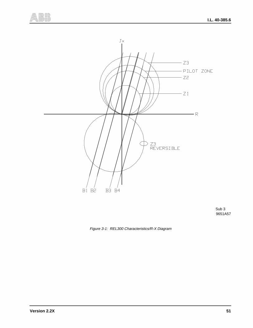
I.L. 40-385.6
Version 2.2X 51
9651A57Sub 3
Figure 3-1: REL300 Characteristics/R-X Diagram
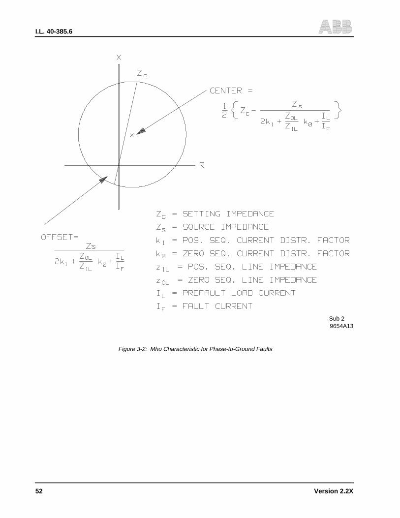
I.L. 40-385.6
52 Version 2.2X
9654A13Sub 2
Figure 3-2: Mho Characteristic for Phase-to-Ground Faults

I.L. 40-385.6
Version 2.2X 53
9654A14Sub 1
9654A15Sub 1
Figure 3-3: Mho Characteristics for Three-Phase Faults (No Load Flow)
Figure 3-4: Mho Characteristics for Phase-to-Phase and Two Phase-to-Ground Faults (No Load Flow)

I.L. 40-385.6
54 Version 2.2X
9661
A16
Sub
2
Fig
ure
3-5:
RE
L300
Zon
e 1
Trip
Log
ic
*Den
otes
Cha
nge
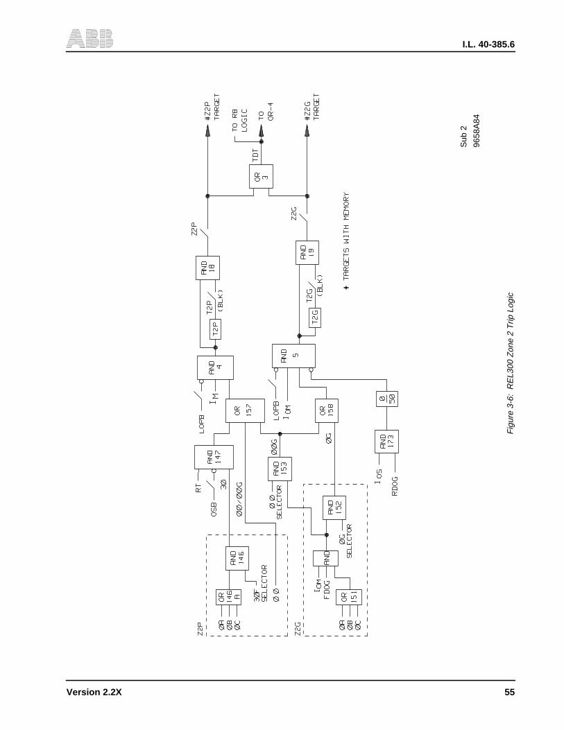
I.L. 40-385.6
Version 2.2X 55
9658
A84
Sub
2
Fig
ure
3-6:
RE
L300
Zon
e 2
Trip
Log
ic
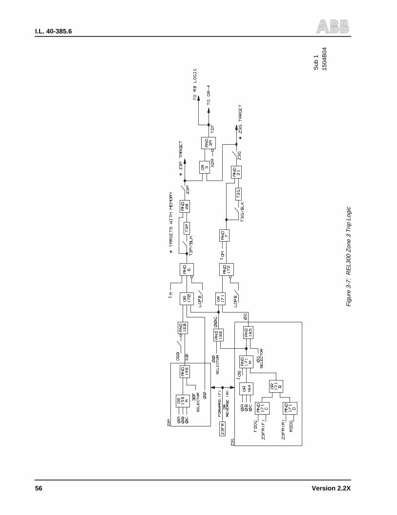
I.L. 40-385.6
56 Version 2.2X
1504
B04
Sub
1
Fig
ure
3-7:
RE
L300
Zon
e 3
Trip
Log
ic
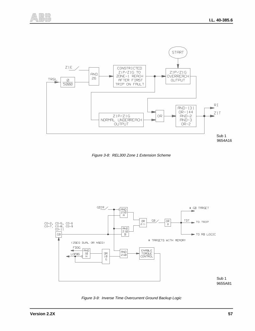
I.L. 40-385.6
Version 2.2X 57
9654A16Sub 1
Sub 19655A81
Figure 3-8: REL300 Zone 1 Extension Scheme
Figure 3-9: Inverse Time Overcurrent Ground Backup Logic
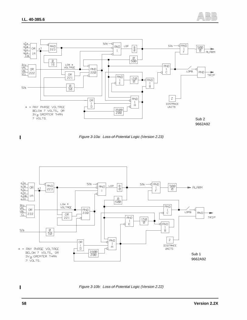
I.L. 40-385.6
58 Version 2.2X
9662A92Sub 2
Figure 3-10a: Loss-of-Potential Logic (Version 2.23)
9662A92Sub 1
Figure 3-10b: Loss-of-Potential Logic (Version 2.22)
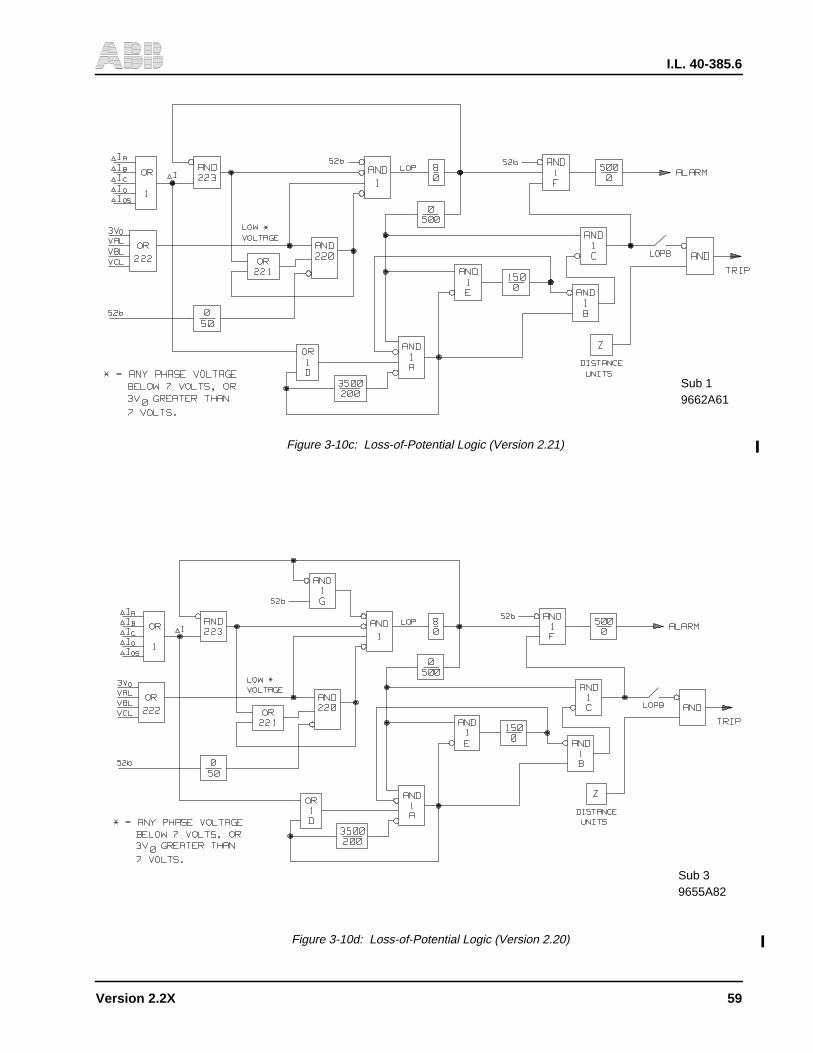
I.L. 40-385.6
Version 2.2X 59
9662A61Sub 1
Figure 3-10c: Loss-of-Potential Logic (Version 2.21)
Figure 3-10d: Loss-of-Potential Logic (Version 2.20)
9655A82Sub 3
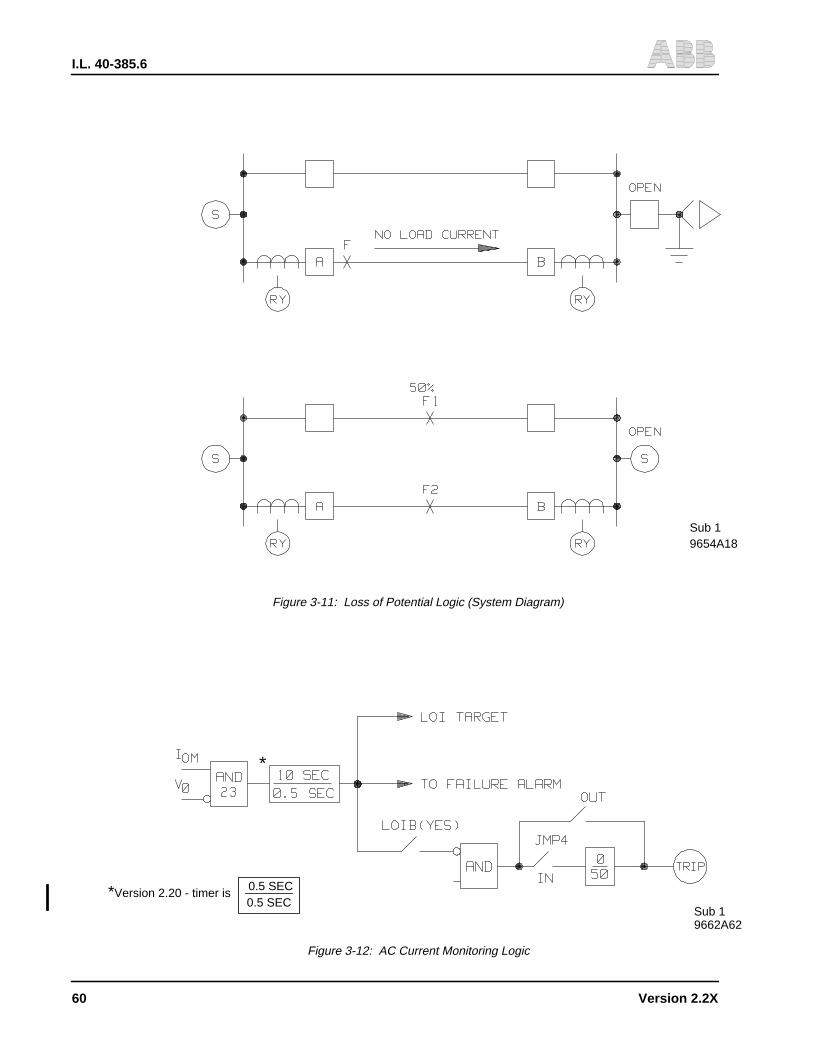
I.L. 40-385.6
60 Version 2.2X
9654A18Sub 1
*
*Version 2.20 - timer is0.5 SEC 0.5 SEC
Sub 19662A62
Figure 3-12: AC Current Monitoring Logic
Figure 3-11: Loss of Potential Logic (System Diagram)
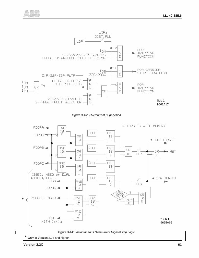
I.L. 40-385.6
Version 2.2X 61
9665A65*Sub 1
*
9661A17Sub 1
Figure 3-13: Overcurrent Supervision
Figure 3-14: Instantaneous Overcurrent Highset Trip Logic
* Only in Version 2.23 and higher
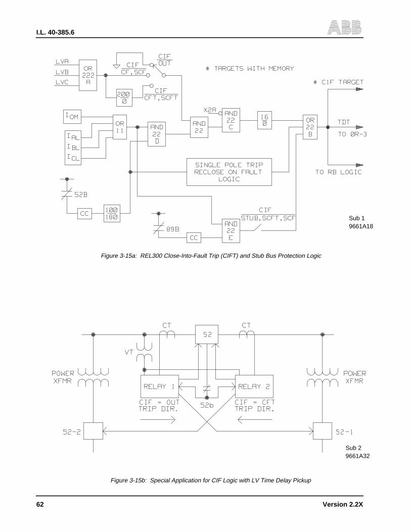
I.L. 40-385.6
62 Version 2.2X
9661A18Sub 1
9661A32Sub 2
Figure 3-15a: REL300 Close-Into-Fault Trip (CIFT) and Stub Bus Protection Logic
Figure 3-15b: Special Application for CIF Logic with LV Time Delay Pickup
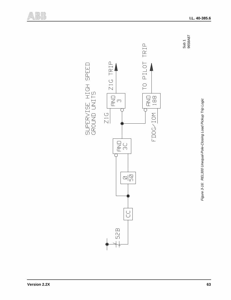
I.L. 40-385.6
Version 2.2X 63
9658
A87
Sub
1
Fig
ure
3-16
:R
EL3
00 U
nequ
al-P
ole-
Clo
sing
Loa
d P
icku
p T
rip L
ogic
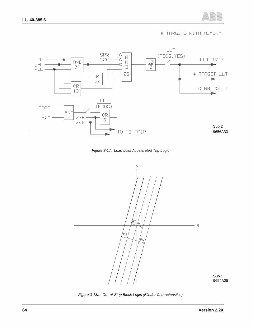
I.L. 40-385.6
64 Version 2.2X
9656A33
Sub 2
9654A25Sub 1
Figure 3-17: Load Loss Accelerated Trip Logic
Figure 3-18a: Out-of-Step Block Logic (Blinder Characteristics)
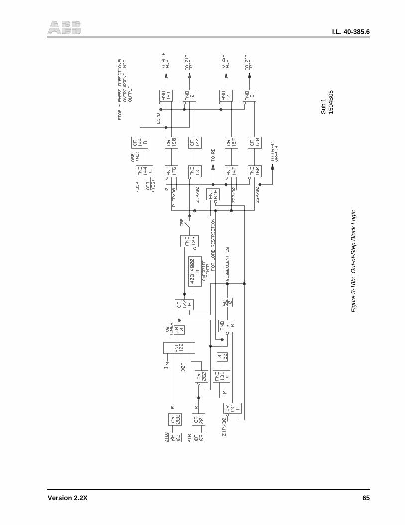
I.L. 40-385.6
Version 2.2X 65
1504
B05
Sub
1
Fig
ure
3-18
b:O
ut-o
f-S
tep
Blo
ck L
ogic

I.L. 40-385.6
66 Version 2.2X
1504
B45
Sub
1
Fig
ure
3-19
:R
eclo
sing
Initi
atio
n Lo
gic
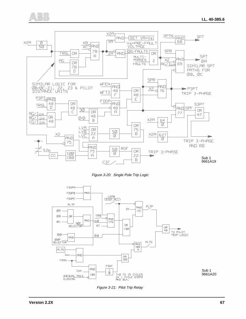
I.L. 40-385.6
Version 2.2X 67
9661A19Sub 1
9661A20Sub 1
Figure 3-21: Pilot Trip Relay
Figure 3-20: Single Pole Trip Logic

I.L. 40-385.6
68 Version 2.2X
9654A26Sub 2
1504B46Sub 1
Figure 3-22: POTT/Unblocking Pilot Trip Logic
Figure 3-23: Carrier Keying/Receiving Logic in POTT/Unblocking Schemes
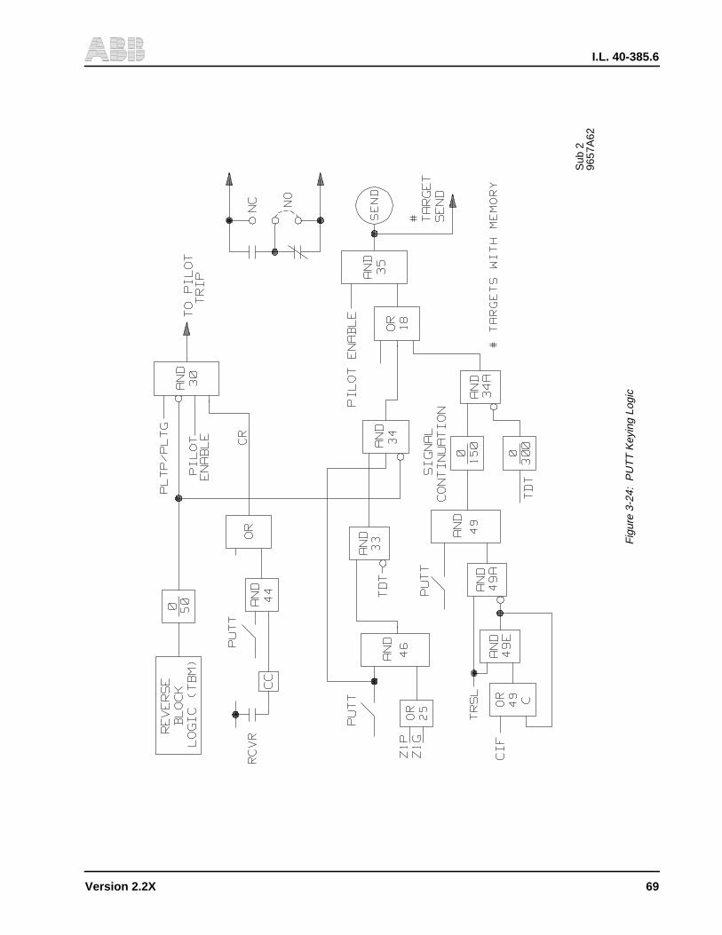
I.L. 40-385.6
Version 2.2X 69
Sub
296
57A
62
Fig
ure
3-24
:P
UT
T K
eyin
g Lo
gic
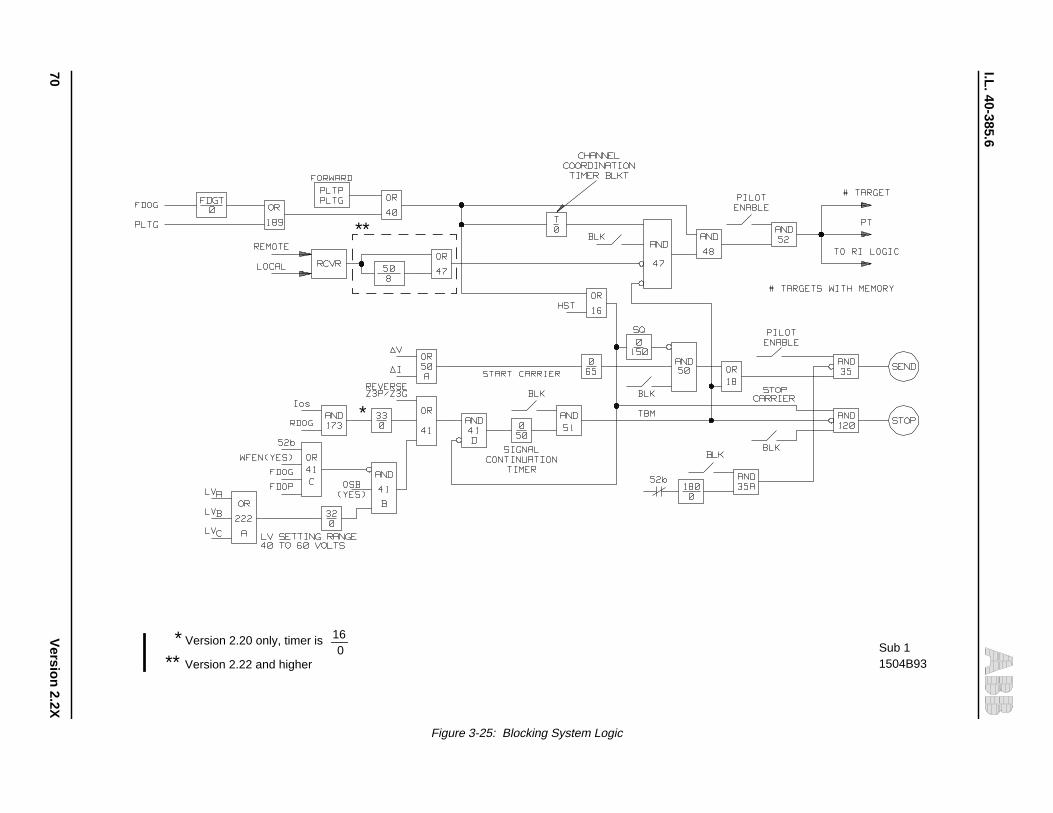
I.L. 40-385.6
70V
ersion 2.2X
1504B93Sub 1
** Version 2.22 and higher
* Version 2.20 only, timer is
*
**
160
Figure 3-25: Blocking System Logic

I.L. 40-385.6
Version 2.2X 71
Sub 29655A86
Figure 3-26: PLTG Supplemented by FDOG
Figure 3-27: Power Reversed on POTT/Unblocking Schemes
9654A17Sub 1

I.L. 40-385.6
72 Version 2.2X
9654A29Sub 1
9654A30Sub 1
Figure 3-28: Unequal Pole Closing on Fault
Figure 3-29: Additional Logic for POTT/Unblocking Schemes on 3-Terminal Line Application
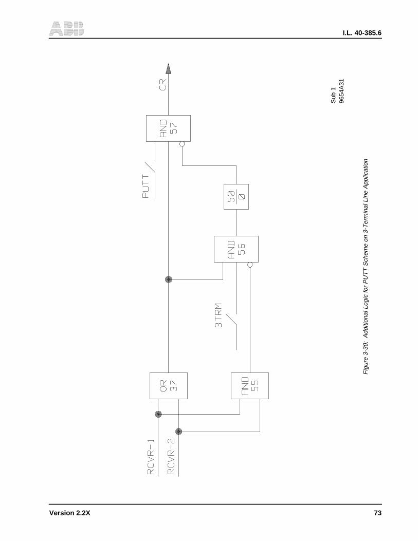
I.L. 40-385.6
Version 2.2X 73
9654
A31
Sub
1
Fig
ure
3-30
:A
dditi
onal
Log
ic fo
r P
UT
T S
chem
e on
3-T
erm
inal
Lin
e A
pplic
atio
n
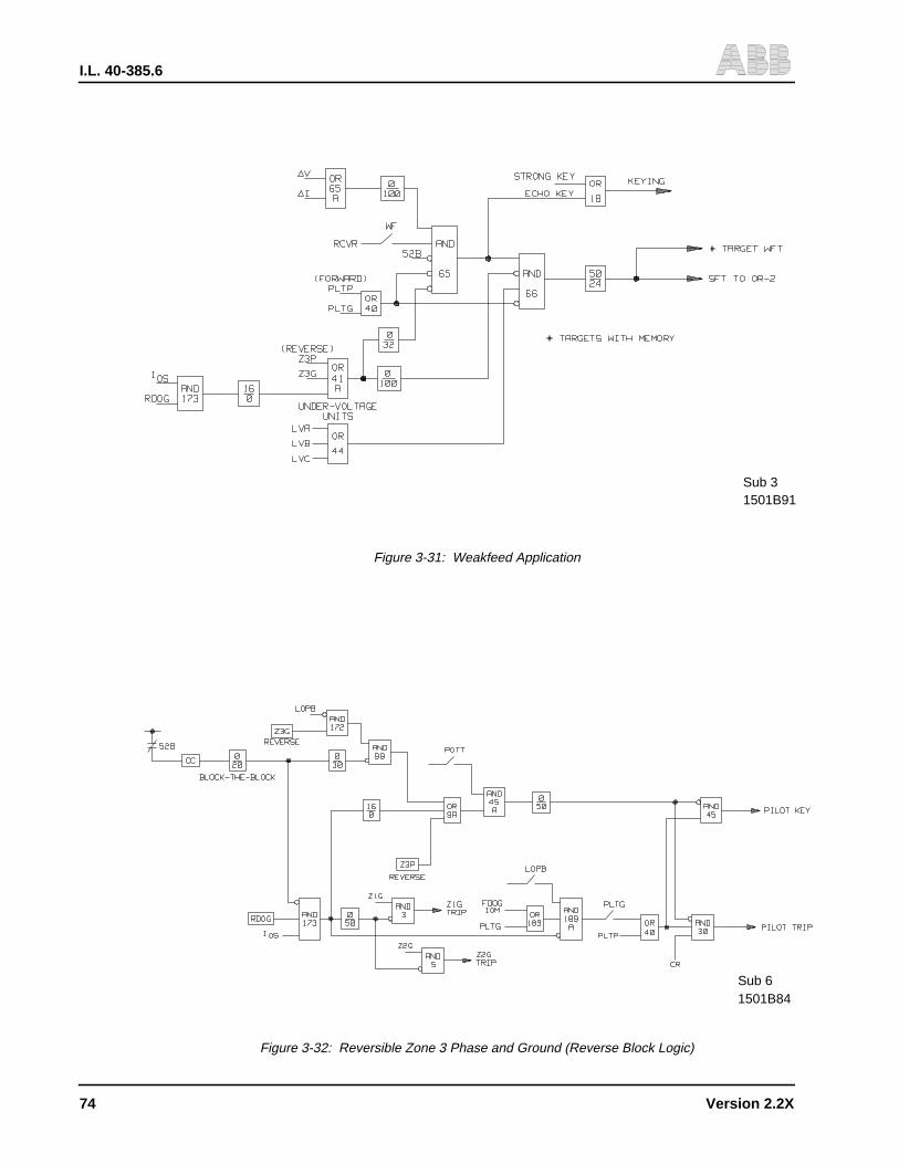
I.L. 40-385.6
74 Version 2.2X
1501B91Sub 3
1501B84Sub 6
Figure 3-32: Reversible Zone 3 Phase and Ground (Reverse Block Logic)
Figure 3-31: Weakfeed Application

I.L. 40-385.6
Version 2.2X 75
Sub
215
04B
08
Fig
ure
3-33
:C
ompo
site
Sig
nal F
or P
rogr
amm
able
Out
put C
onta
cts

I.L. 40-385.6
76 Version 2.2X
TABLE 3-1: REL300 CATALOG NUMBERS
Typical Catalog Number
REL300 DIGITAL MD 3 B 1 S P F R GRELAY SYSTEM (50/60 HZ)
TRIP
Three Pole Trip 3Single Pole Trip 1Three Pole Trip w/Programmable Contacts * 8
CURRENT INPUT
1A A5A B
BATTERY SUPPLY VOLTAGE
48/60 Vdc 4110/125 Vdc 1220/250 Vdc 2
POWER SWING BLOCK
Power Swing Block S
PILOT SYSTEM/CHANNEL INTERFACE
Pilot System-Channel Interface PNon-Pilot System, No Channel Interface N
TEST SWITCHES
FT-14 Switches FNo FT-14 Switches N
COMMUNICATION INTERFACE
RS-232C RRS-232C (with IRIG - B port) BINCOM C
SOFTWARE OPTION(Oscillographic Data Storage STD)**
Version 2.0X GVersion 2.1X AVersion 2.2X B
* Available in 2.1X and 2.2X Versions only
** Remote Communications Program (RCP) software and
Optional Oscillographic and Recordingsoftware (OSCAR) can be ordered separately,catalog number SWOSC01
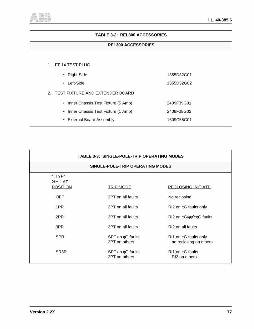
I.L. 40-385.6
Version 2.2X 77
TABLE 3-2: REL300 ACCESSORIES
REL300 ACCESSORIES
1. FT-14 TEST PLUG
• Right-Side 1355D32G01
• Left-Side 1355D32G02
2. TEST FIXTURE AND EXTENDER BOARD
• Inner Chassis Test Fixture (5 Amp) 2409F39G01
• Inner Chassis Test Fixture (1 Amp) 2409F39G02
• External Board Assembly 1609C55G01
TABLE 3-3: SINGLE-POLE-TRIP OPERATING MODES
SINGLE-POLE-TRIP OPERATING MODES
“TTYP”SET ATPOSITION TRIP MODE RECLOSING INITIATE
OFF 3PT on all faults No reclosing
1PR 3PT on all faults RI2 on φG faults only
2PR 3PT on all faults RI2 on φG/φφ/φφG faults
3PR 3PT on all faults RI2 on all faults
SPR SPT on φG faults RI1 on φG faults only3PT on others no reclosing on others
SR3R SPT on φG faults RI1 on φG faults3PT on others RI2 on others

I.L. 40-385.6
78 Version 2.2X
TABLE 3-4: REL300 PROGRAMMABLE OUTPUT CONTACTS
REL300 PROGRAMMABLE OUTPUT CONTACTS
Description Value
1. Z1P trip output Z1P
2. Z1G trip output Z1G
3. Z2P trip output Z2P
4. Z2G trip output Z2G
5. Z3P trip output Z3P
6. Z3G trip output Z3G
7. PLTP trip output PLTP
8. PLTG trip output PLTG
9. High set phase trip output ITP
10. High set ground trip output ITG
11. GB trip output GB
12. Close-into-fault trip output CIFT
13. TBM signal output (BLK/POTT) TBM
14. Pilot in service PLTX
15. OSB pickup OSB
16. Carrier send output SEND
17. FDOG/IOM/FDGT output FDOG
18. Inner blinder 21BI pickup 21BI
19. IOS without timer IOS
20. Phase selector AG AG
21. Phase selector BG BG
22. Phase selector CG CG
23. Phase selector AB of ABG AB
24. Phase selector BC or BCG BC
25. Phase selector CA or CAG CA
26. Phase selector ABC with TRSL ABC
27. LOP with delay pickup/without delay dropout LOP
28. RCVR-1 or RCVR-2 CR
29. POTT scheme — ECHO (either weakfeed or open breaker key) ECHO/STOP
BLK scheme — STOP
30. LLT or WFT LLT/WFT
Refer to Figure 3-33 (page 75) for the signals and logics.
I.L. 40-385.6
Version 2.2X 79
Section 4. INSTALLATION, OPERATION AND MAINTENANCE
! WARNING
Check jumper #3 on the Microprocessor module for phase rotation ABC or ACB. Re-move jumper#3 for system ABC rotation. Refer to section 1.8 (page 7) for ACB system.
4.1 SEPARATING THE INNER AND OUTERCHASSIS
It is recommended that the user of this equipment become acquainted with the information inthese instructions before energizing the REL300 and associated assemblies. Failure to ob-serve this precaution may result in damage to the equipment.
All integrated circuits used on the modules are sensitive to and can be damaged by the dis-charge of static electricity. Electrostatic discharge precautions should be observed when oper-ating or testing the REL300.
! CAUTION
Use the following procedure when separating the inner chassis from the outer chas-sis; failure to observe this precaution can cause personal injury, undesired tripping ofoutputs and component damage.
a. Unscrew the front panel screws.
b. If the REL300 does not have FT-14 switches, but has a power switch on the front panel,turn “OFF” the power switch before sliding out the inner chassis.
c. If the REL300 has FT-14 switches:
1) Remove the FT-14 covers (one on each side of the REL300).
2) Open all FT-14 switches.
! WARNING
Do Not Touch any FT-14 switch; they may be energized.
3) Slide out the inner chassis.
4) Close all FT-14 switches.
5) Replace the FT-14 covers.
d. Reverse procedures above when replacing the inner chassis into the outer chassis.

I.L. 40-385.6
80 Version 2.2X
4.2 TEST PLUGS AND FT-14 SWITCHES
Test Plugs are available as accessories (see Table 3-2, page 77); they are inserted into the FT-14 switches for the purpose of System Function Tests. When the Test Plugs are inserted, theFT switch #13 (BP) and #14 (BN) must remain closed.
4.3 EXTERNAL WIRING
All external electrical connections pass through the Backplate (Figure 4-1, page 93er chassis.If the REL300 is used without the FT-14 switch, six 14-terminal connectors on the Backplate(TB1 through TB6) are used. If the FT-14 switch (option) is included, using the two peripheralareas of the REL300 cabinet, then only four of the 14-terminal connectors (TB2 through TB5)are used. Three DIN connectors (J11, J12, J13) allow for the removal of the outer chassis(Backplane module) from the inner chassis (Interconnect module).
Electrical inputs to the Backplane module, which are routed either directly through the Back-plate or through the FT-14 switch to the Backplate, include (Figure 4-1, page 93):
• VA, VB, VC and VN
• IA/IAR, IB/IBR, IC/ICR, and IP/IN
• BP (48, 125 or 250 Vdc) and BN (negative)
Analog input circuitry consists of four current transformers (IA, IB, IC, and IN), three voltagetransformers, (VA, VB and VC), and low-pass filters. The seven transformers are located on theBackplane PC Board. The primary winding of all seven transformers are directly-connected tothe input terminal TB6/1 through 12; the secondary windings are connected through the Inter-connect module to the Filter module.
As shown in Figures 4-1 and 4-2 (page 93 and page 94), dry contact outputs for breaker failureinitiation (BFI), reclosing initiation (RI), reclosing block (RB), failure alarm (AL1), trip alarm(AL2), SEND and STOP are located on the Backplane PC Board. Optical isolators are for PilotEnable, External Reset, Receiver #1 and #2, 52a, 52b, SBP (89b) and studs for chassis ground(GND) and location for the Communication Interface are also shown.
As shown in Figure 4-3 (page 95), the power system ac quantities (Va, Vb, Vc, Vn, Ia, Ib, Ic andIn), as well as the dc source are connected to the left side FT-14 switch (front view). All the tripcontact outputs are connected to the right-side FT-14 switch (front view). Switches 13 and 14on FT-14 may be used for disabling the Breaker Failure Initiation/Reclosing Initiation (BFI/RI)control logic.
The INCOM® or RS232 PONI (Product Operated Network Interface) communication box ismounted through the Backplate of the outer chassis and connected to the Backplane module,and remote settings (see section 4.7, page 87).
4.4 REL300 FRONT PANEL DISPLAY
The front panel display consists of a vacuum fluorescent display, seven LED indicators, sevenpush-button switches, and five test points (as shown in Figure 1-1, page 8).

I.L. 40-385.6
Version 2.2X 81
4.4.1 Vacuum Fluorescent Display
The vacuum fluorescent display (blue color) contains four alphanumeric characters for both thefunction field and the value field. All the letters or numbers are fourteen segment form (7.88mmx 13mm in size).
A software display saver is built in. The REL300 display will be on only for 5 minutes after turn-ing on the dc power supply or depressing any one of the front panel push-button or detectingany fault on the line.
4.4.2 LED Indicators
There are seven LED indicators on the front panel display:
• 1 “relay-in-service” indicator
• 1 “value accepted” indicator
• 5 display-select indicators
When the “Relay-in-Service” LED illuminates, the REL300 Relay is in service, there is dc powerto the relay and the relay has passed the self-check and self-test. The LED is turned “OFF” ifthe Relay-in-service relay has at least one of the internal failures shown in the “Test” mode, andthe trip will be blocked.
The “Value Accepted” LED flashes only once, to indicate that a value has been entered suc-cessfully.
The five indicators used for the display selection are:
• Settings
• Volts/Amps/Angle
• Last Fault
• Previous Fault
• Test
One of these indicators is always illuminated, indicating the mode selected. The display will beblocked momentarily every minute for the purpose of self-check; this will not affect the relayprotection function.
4.4.3 Push-button Switches
The front panel contains seven push-button switches:
• Display Select
• Reset Targets
• Function Raise
• Function Lower
I.L. 40-385.6
82 Version 2.2X
• Value Raise
• Value Lower
• Enter (recessed for security purposes)
The “Display Select” push-button is used to select one of the five display modes, which is indi-cated when the proper LED illuminates. When a fault is detected, the “Last Fault” flashes onceper second. If two faults are recorded, the “Last Fault” flashes twice per second, and the priorfault will be moved from “Last Fault” to “Previous Fault”. The new fault data will be stored in the“Last Fault” register. By depressing the “Reset Targets” push-button, the flashing LED indica-tors are cleared, and the LED will revert back to the Metering mode. The information in the “Pre-vious Fault” and “Last Fault” will not be reset from the front panel push-button switch, but willbe reset from External Reset (TB5/5 and TB5/6) and the remote reset through the Communi-cation Interface.
The “Function Raise” and “Function Lower” pushbuttons are used to scroll through the informa-tion for the selected display mode. The “Value Raise” and “Value Lower” pushbuttons are usedto scroll through the different values available for each of the five functions. The “Enter” push-button is used to enter (in memory) a new value for settings.
If the display is in “sleep” mode (no readout), by depressing any one of the pushbuttons willresume the illumination of the vacuum fluorescent display.
4.4.4 Test Points
Five test points -24V, + 5V, -12V, +12 Volts and common are removed from the front panel forthis REL300 version.
4.5 FRONT PANEL OPERATION
The front (operator) panel provides a convenient means of checking or changing settings, andfor checking relay unit operations after a fault. Information on fault location, trip types, phase,operating units, and breakers which tripped become available by using the pushbuttons to stepthrough the information. Targets (fault data) from the last two faults are retained, even if therelay is deenergized. The operator is notified that targets are available by a red flashing LEDon the front panel; in addition, alarm 2 output-relay contacts are provided for the external an-nunciators.
The operator can identify nonfault voltage, current and phase angle on the front panel display.Settings can be checked easily, however, any change to the settings requires the use of thepushbuttons. When relay is in the normal operating mode, it is good practice to set the LED onthe Volts/Amps/Angle mode.
4.5.1 Settings Mode
In order to determine the REL300 settings that have been entered into the system, continuallydepress the “DISPLAY SELECT” push-button until the “SETTINGS” LED is illuminated. Thendepress the “FUNCTION RAISE” or “FUNCTION LOWER” push-button, in order to scrollthrough the REL300 SETTINGS functions (see Table 4-1, page 96). For each settings functiondisplayed, depress the “VALUE RAISE” or “VALUE LOWER” push-button in order to scrollthrough the REL300 values available for the particular function. (Each value that appears, aseach different function appears in the function field, is considered to be the “current value” usedfor that particular function.)
I.L. 40-385.6
Version 2.2X 83
In order to change the “current value” of a particular settings function, “RAISE” or “LOWER” theFUNCTION field until the desired function appears (e.g., “RP”). Then “RAISE” or “LOWER” thevalues in the VALUE field until the desired value appears. If the “ENTER” push-button (re-cessed for security purposes) is depressed, the value which appears in the VALUE field willreplace the “current value” in memory; but only if the “VALUE ACCEPTED” LED flashes onceto indicate that the value has been successfully entered into the system.
For reasons of security, a plastic screw is used to cover the ENTER push-button. A wire canbe used to lock the plastic screw and to prevent any unauthorized personnel from changing thesettings.
4.5.2 Metering (Volts/Amps/Angle) Mode
When the Volts/Amps/Angle LED is selected by the “Display Select” push-button, the phase A,B, C voltages, currents and phase angles are available for on-line display during normal oper-ation. All measured values can be shown by scrolling the “Raise” or “Lower” push-button in theFUNCTION field. The values on the display are dependent on the settings of RP (read primary);RP= YES for the primary side values and RP = NO for the secondary values. Conditions suchas loss-of-potential, loss-of-current and out-of-step blocking can also be monitored. The func-tion names and values are shown in Table 4-2 (page 99).
NOTE: All displayed Phase Angles use V A as reference.
The phase rotation of ABC or ACB is also displayed on the metering mode depends onthe setting of JMP3 position on processor module.
4.5.3 Target (Last and Previous Fault) Mode
The REL300 system saves the latest 16 faults records. The “LAST FAULT” information is of themost recent fault, the “PREVIOUS FAULT” information is of the fault prior to the “LAST FAULT”.These displays contain the target information along with the “frozen” data at the time of trip.The “LAST FAULT” register shows one or two records stored by flashing the LED once or twiceper second, respectively. These records can be deleted by External Reset voltage TB/5 (+) andTB5/6 (-) or through a remote communication interface. The front panel (RESET) push-buttonallows the user to reset the flashing LED to Metering position only. It will not erase the fault information.
Different types of faults with related descriptions are shown in Table 4-3. As soon as a faultevent is detected, the most recent two sets of target data are available for display. If the FDATis set at “TRIP”, the “Last Fault” is the data associated with the most recent trip event. The “Pre-vious Fault” contains the data from the prior trip event. If a single fault occurs, the “Last Fault”LED flashes. If a reclosing is applied and the system trips, the original “LAST FAULT” informa-tion will be transferred to the “Previous Fault” memory. The latest trip information will be storedin the “Last Fault” memory, and its LED flashes twice per second. If FDAT is set at Z2TR, twoevents (Zone 2 pickup or trip) will be stored. If FDAT is set at Z2/Z3, the two events will be eitherZone 2 pickup or Zone 3 pickup or any type of trip. The same description applies to a remotecommunication which can store up to 16 events.
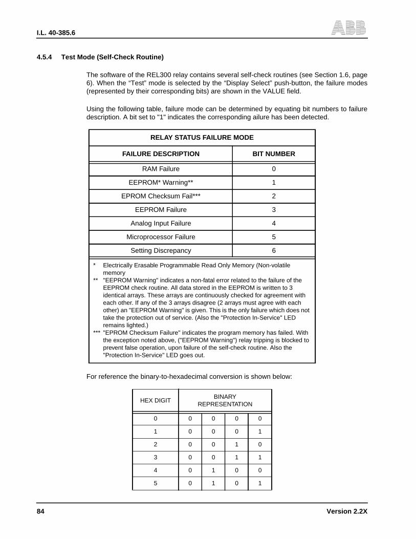
I.L. 40-385.6
84 Version 2.2X
4.5.4 Test Mode (Self-Check Routine)
The software of the REL300 relay contains several self-check routines (see Section 1.6, page6). When the “Test” mode is selected by the “Display Select” push-button, the failure modes(represented by their corresponding bits) are shown in the VALUE field.
Using the following table, failure mode can be determined by equating bit numbers to failuredescription. A bit set to "1" indicates the corresponding ailure has been detected.
For reference the binary-to-hexadecimal conversion is shown below:
RELAY STATUS FAILURE MODE
FAILURE DESCRIPTION BIT NUMBER
RAM Failure 0
EEPROM* Warning** 1
EPROM Checksum Fail*** 2
EEPROM Failure 3
Analog Input Failure 4
Microprocessor Failure 5
Setting Discrepancy 6
* Electrically Erasable Programmable Read Only Memory (Non-volatilememory
** "EEPROM Warning" indicates a non-fatal error related to the failure of theEEPROM check routine. All data stored in the EEPROM is written to 3identical arrays. These arrays are continuously checked for agreement witheach other. If any of the 3 arrays disagree (2 arrays must agree with eachother) an "EEPROM Warning" is given. This is the only failure which does nottake the protection out of service. (Also the "Protection In-Service" LEDremains lighted.)
*** "EPROM Checksum Failure" indicates the program memory has failed. Withthe exception noted above, ("EEPROM Warning") relay tripping is blocked toprevent false operation, upon failure of the self-check routine. Also the"Protection In-Service" LED goes out.
HEX DIGITBINARY
REPRESENTATION
0 0 0 0 0
1 0 0 0 1
2 0 0 1 0
3 0 0 1 1
4 0 1 0 0
5 0 1 0 1
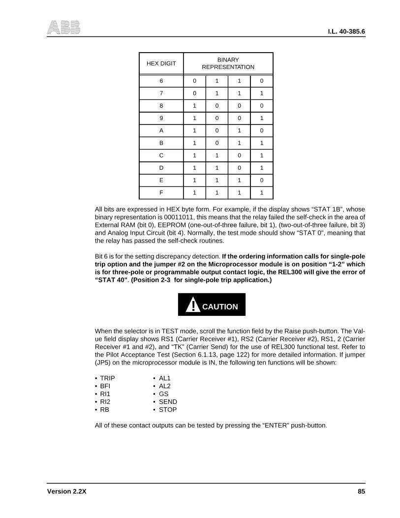
I.L. 40-385.6
Version 2.2X 85
All bits are expressed in HEX byte form. For example, if the display shows “STAT 1B”, whosebinary representation is 00011011, this means that the relay failed the self-check in the area ofExternal RAM (bit 0), EEPROM (one-out-of-three failure, bit 1), (two-out-of-three failure, bit 3)and Analog Input Circuit (bit 4). Normally, the test mode should show “STAT 0", meaning thatthe relay has passed the self-check routines.
Bit 6 is for the setting discrepancy detection. If the ordering information calls for single-poletrip option and the jumper #2 on the Microprocessor module is on position “1-2” whichis for three-pole or programmable output contact logic, the REL300 will give the error of“STAT 40" . (Position 2-3 for single-pole trip application.)
! CAUTION
When the selector is in TEST mode, scroll the function field by the Raise push-button. The Val-ue field display shows RS1 (Carrier Receiver #1), RS2 (Carrier Receiver #2), RS1, 2 (CarrierReceiver #1 and #2), and “TK” (Carrier Send) for the use of REL300 functional test. Refer tothe Pilot Acceptance Test (Section 6.1.13, page 122) for more detailed information. If jumper(JP5) on the microprocessor module is IN, the following ten functions will be shown:
• TRIP • AL1• BFI • AL2• RI1 • GS• RI2 • SEND• RB • STOP
All of these contact outputs can be tested by pressing the “ENTER” push-button.
6 0 1 1 0
7 0 1 1 1
8 1 0 0 0
9 1 0 0 1
A 1 0 1 0
B 1 0 1 1
C 1 1 0 1
D 1 1 0 1
E 1 1 1 0
F 1 1 1 1
HEX DIGITBINARY
REPRESENTATION
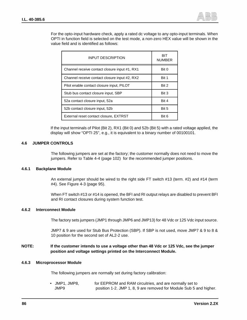
I.L. 40-385.6
86 Version 2.2X
For the opto-input hardware check, apply a rated dc voltage to any opto-input terminals. WhenOPTI in function field is selected on the test mode, a non-zero HEX value will be shown in thevalue field and is identified as follows:
If the input terminals of Pilot (Bit 2), RX1 (Bit 0) and 52b (Bit 5) with a rated voltage applied, thedisplay will show “OPTI 25", e.g., it is equivalent to a binary number of 00100101.
4.6 JUMPER CONTROLS
The following jumpers are set at the factory; the customer normally does not need to move thejumpers. Refer to Table 4-4 (page 102) for the recommended jumper positions.
4.6.1 Backplane Module
An external jumper should be wired to the right side FT switch #13 (term. #2) and #14 (term#4). See Figure 4-3 (page 95).
When FT switch #13 or #14 is opened, the BFI and RI output relays are disabled to prevent BFIand RI contact closures during system function test.
4.6.2 Interconnect Module
The factory sets jumpers (JMP1 through JMP6 and JMP13) for 48 Vdc or 125 Vdc input source.
JMP7 & 9 are used for Stub Bus Protection (SBP). If SBP is not used, move JMP7 & 9 to 8 &10 position for the second set of AL2-2 use.
NOTE: If the customer intends to use a voltage other than 48 Vdc or 125 Vdc, see the jumperposition and voltage settings printed on the Interconnect Module.
4.6.3 Microprocessor Module
The following jumpers are normally set during factory calibration:
• JMP1, JMP8, for EEPROM and RAM circuitries, and are normally set toJMP9 position 1-2. JMP 1, 8, 9 are removed for Module Sub 5 and higher.
INPUT DESCRIPTIONBIT
NUMBER
Channel receive contact closure input #1, RX1 Bit 0
Channel receive contact closure input #2, RX2 Bit 1
Pilot enable contact closure input, PILOT Bit 2
Stub bus contact closure input, SBP Bit 3
52a contact closure input, 52a Bit 4
52b contact closure input, 52b Bit 5
External reset contact closure, EXTRST Bit 6
I.L. 40-385.6
Version 2.2X 87
• JMP2 normally set to position 1-2 for three pole trip or programmableoutput contact logic. Set position 2-3 for single-pole trip logiconly.
• JMP3 Phase rotation; “OUT” for ABC, “IN” for ACB
• JMP4 set to “IN” for trip contact with dropout time delay.
• JMP5 set to “IN” for output contact tests. Normally, set to “OUT”.
• JMP6 normally set to “OUT” position; set to “IN” when making A/Dconverter calibration.
• JMP10, JMP11, Not usedJMP12 (or spare jumpers)
NOTE: Should the customer need to gain access to any of the jumpers (above), see Table4-4 (page 102).
4.6.4 Power Supply Module
• JMP1 Carrier StopPosition 1-2 for NO contact and 2-3 for NC contact output
• JMP2 Carrier SENDPosition 1-2 for NO contact and 2-3 for NC contact output
4.6.5 Programmable Output Contact Module
• JMP1 Selection for NO or NC output contact of OC5
• JMP2 Selection for NO or NC output contact of OC6
• JMP3 Selection for NO or NC output contact of OC7
• JMP4 Selection for NO or NC output contact of OC8
4.7 COMMUNICATION PORT USE
4.7.1 Introduction
REL 300 can be communicated with for target data, settings, etc., through the man-machine in-terface (MMI), The relay can also be communicated with via the communication (comm.) port.Comm port communications, provide the user with more information than is available with theMMI. For example, all 16 targets are available and a more friendly user interface for settings canbe accessed (all settings are displayed on a single screen on the user’s PC). This section willprovide the details of the comm port options, personal computer requirements, connecting ca-bles and all information necessary to communicate with and extract data from the relay. Addi-tional communications details are contained in I.L. 40-603, (RCP) Remote CommunicationProgram. As stated in Section 1.7 (page 7), RCP is required for all comm. port communications.Information about the communications protocol can be found in the RCP I.L.
4.7.2 Communication Port Options
REL 300 is supplied with a rear communications port. If the network interface is not specified,a RS-232C (hardware standard) communications port is supplied. Network interface comm. portoption, NET-PONI (see I.L. 40-611 for details) allows the connection of the relay with many oth-er devices to a 2-wire network. A detailed discussion of networking capabilities can be found inAD 40-600, Substation Control and Communications Application Guide .
I.L. 40-385.6
88 Version 2.2X
RS-232C, rear comm. ports are of the removable, Product Operated Network Interface (PONI)type and are available in two styles. One is identified by a 25 pin (DB-25S) female connector, itis beige or gray and has a single data comm. rate of 1200 bps. The second style is a RS-PONI(see I.L. 40-610 for details) identified by a 9 pin (DB-9P) male connector and externally acces-sible dip switches (next to the connector) for setting the communication data rate. This port op-tion is always black in color, can be set for speeds of 300, 1200, 2400, 4800, or 9600 bps (seeTable 4-7, page 104) and offers an option for IRIG-B time clock, synchronization input.
4.7.3 Personal Computer Requirements
Communication with the relay requires the use of Remote Communication Program (RCP) re-gardless of the comm. port option. RCP is supplied by ABB Relay Division and is run on a per-sonal computer (PC).
NOTE: REL 300 relays should use latest version of RCP.
To run the program requires an IBM AT, PC/2 PC or true compatible with a minimum of 640kilobytes of RAM, 1 hard disk drive, a RS-232C comm. port and a video graphics adapter card.The PC must be running Version 3.3, or higher, MS-DOS.
4.7.4 Connecting Cables
With communication port option the connecting cable requirement can be different. Also, con-necting directly to a PC or connecting to a modem, for remote communication, affects the con-necting cable requirements. Table 4-6 (page 104) provides a summary of a plug pinassignments, pins required and cable connectors.
Some terminology will be defined to aid the user in understanding cable requirements in Table4-6 (page 104). Reference, is often made to the “RS-232C” standard, for data communication.The RS-232C standard describes mechanical, electrical, and functional characteristics. Thisstandard is published by the Electronics Industry Association (EIA) and use of the standard isvoluntary but widely accepted for electronic data transfer. ABB relay communications followsthe RS-232C standard for non-network data communication.
Although the RS-232C standard does not specify a connector shape, the most commonly usedis the “D” shape connector. As stated in Section 4.7.2 (page 87), all ABB relay communicationconnectors are of the “D” shape (such as DB-25S).
Data communication devices are categorized as either Data Terminal Equipment (DTE) or DataCommunication Equipment (DCE). A DTE is any digital device that transmits and/or receivesdata and uses communications equipment for the data transfer. DCE’s are connected to a com-munication line (usually a telephone line) for the purpose of transferring data from one point toanother. In addition to transferring the data, DCE devices are designed to establish, maintain,and terminate the connection. As examples, a computer is a DTE device and a modem is a DCEdevice.
By definition the connector of a DCE is always female (usually DB-9S or 25S). Similarly, DTEsare always male (usually DB-9P or 25P). These definitions apply to the equipment being con-nected and to the connectors on the interconnecting cables.
One additional piece of hardware that is required, in some applications, is a “null” modem. Nullmodem’s function is to connect the transmit line (TXD), pin 2 by RS-232C standard, to the re-
I.L. 40-385.6
Version 2.2X 89
ceive line (RXD), pin 3. A null modem is required when connecting like devices. That is DTE toDTE or DCE to DCE. A DCE to DCE, example, where a null modem is required, is the connec-tion of a 25 pin, PONI to a modem.
A null modem function can be accomplished in the connecting cable or by separate null modempackage. That is, by using a conventional RS-232C cable plus a null modem. One type of nullmodem, available from electronics suppliers, is B & B Electronics Type 232MFNM.
4.7.5 Relay Password and Settings Change Permission
To gain access to certain communication port functions, the REL 300 must have the remote set-ting capability permission “SETR” set to “YES” and knowledge of the relay password is re-quired. All communications port functions listed below require “SETR” set to “YES” before theactions can be performed:
Update/Change SettingsUpdate Programmable Contact SettingsEnable Local Settings (capability)Disable Local Settings (capability)Activate Output Relays (contact testing function)
Access control, both setting permission and password knowledge is required for all communi-cation port options.
Before attempting any of the above functions, the setting of “SETR” must be verified via thefront panel MMI. Using the setting change procedure in Section 4.5 (page 82), verify or change“SETR” such that it is set to “YES” .
Using comm. port communications, the ability to change settings from the MMI can be dis-abled.The RCP, Password Menu Choice “Disable Local Settings” when selected, will block set-ting changes via the MMI. Blocking the front panel setting changes, may be useful for situationsin which the access to the relay cannot be secured from tampering by unauthorized persons.
Password:
When the REL 300 is received from the factory or if the user loses the relay password, a newpassword can be assigned with the following procedure:
1) Turn off the relay dc supply voltage for a few seconds,
2) Restore the dc supply voltage and wait for the relay to complete the self check/start-uproutine,
3) Using RCP, perform the Password Menu choice “Set Relay Password”,
4) Use the word “password” when prompted for the “current relay password” and
5) Then enter a new password.
NOTE: Password setting change procedure must be completed within 15 minutesof energizing relay or “password” will not be accepted as the “current”password.
I.L. 40-385.6
90 Version 2.2X
4.8 SIXTEEN FAULT TARGET DATA
The REL300 saves the latest 16 fault records, but only the latest two fault records can be ac-cessed from the front panel. For complete 16 fault data, one of the communication interfacedevices are necessary. The activation of fault data storage is controlled by setting FDAT. (Referto Section 3.4.19 (page 38) for detailed information.) The 16 intermediate fault targets are astandard feature. The activation of data storage is based on the setting of the optional OSC(see next section).
4.9 OSCILLOGRAPHIC DATA (Standard) (Optional Graphic Feature)
Sixteen sets of oscillographic data are stored in REL300. Each set includes seven analog trac-es (Va, Vb, Vc, Ia, Ib, Ic and In), with one cycle pre-fault and 7-cycle fault information, and 20sets of digital data based on 8 samples per cycle.
The oscillographic data (OSC) collection can be set for TRIP, Z2TR, Z2/Z3, and ∆V∆I. For set-ting of OSC = TRIP, data are collected for the trip events. The data collection is started from∆V∆I if the trip occurs within 7 cycles. For OSC = Z2TR, the data collection is triggered by Zone2 pickup or any types of trip. For OSC = Z2/Z3, the collection is triggered by either Zone 2 orZone 3 pickup (including the Zone 3 reverse setting) or trip. For OSC = ∆V∆I, the data collectionis caused by any line disturbance, e.g., a sudden phase current change (by 1 amp) or a groundcurrent change (by 0.5 Amp), or a voltage change (∆V) greater than 7Vdc.
NOTE: Setting at ∆V∆I is not recommended because a lot of meaningless data will be stored,such as breaker opening or closing, etc.
NOTE: The (GS) General Start contact will activate for any ∆V∆I.
4.10 PROGRAMMABLE CONTACT OUTPUTS(Optional Feature)
The optional programmable output contact module consists of 8 relays, 4 with heavy duty NOcontacts (OC1 to OC4) and 4 with standard contacts (OC5 to OC8) with jumper selection forNO or NC outputs. Contacts OC4 and OC8 provide timers for delay pickup and/or delay drop-out. The ranges of timers are 0 to 5 seconds in 0.01 seconds steps with an error of 1 cycle.Every Contact (OC1 to OC8) can be programmed independently based on one or all of the 30pre-assigned signals with AND/OR/NOT logic combination. These 30 signals are listed in Table3-4 and Figure 3-33. All 8 output settings can only be performed through remote WRELCOM™communication. An example of this programmable contact output WRELCOM™ screen isshown in Table 4-5 (page 103).
Selecting a function for an output contact is made by pressing the INSERT key with the cursorpositioned at the crossing of the desired function and contact number. By pressing the functionkey F2 on the keyboard, the logic true (T) or logic negation (F) should be switched.
The DELETE key can be used to de-select a previously selected function.
If a contact is to be controlled by several functions, the same procedure applies for each func-tion, without forgetting the combining operator OR or AND. To input a pickup or dropout time
I.L. 40-385.6
Version 2.2X 91
delay (contact #4 or #8 only), press ENTER with the cursor positioned on the appropriate timedelay. Press ENTER again to accept the desired time delay.
4.11 ROUTINE VISUAL INSPECTION
With the exception of Routine Visual Inspection, the REL300 relay assembly should be main-tenance-free for one year. A program of Routine Visual Inspection should include:
• Condition of cabinet or other housing
• Tightness of mounting hardware and fuses
• Proper seating of plug-in relays and subassemblies
• Condition of external wiring
• Appearance of printed circuit boards and components
• Signs of overheating in equipment
4.12 ACCEPTANCE TESTING
The customer should perform the REL300 Acceptance Tests on receipt of shipment.
4.13 NORMAL PRECAUTIONS
Troubleshooting is not recommended due to the sophistication of the Microprocessor unit.
! CAUTION
With the exception of checking to insure proper mating of connectors, or setting jump-ers, the following procedures are normally not recommended. (If there is a problemwith the REL300, it should be returned to the factory. See PREFACE.)
4.14 DISASSEMBLY PROCEDURES
a. Remove the inner chassis from the outer chassis, by unscrewing the two lockscrews (onthe front panel), and unsnapping the two covers from the (optional) FT-14 switches, if theFT-14 switches are a part of the REL300 system.
NOTE: The inner-chassis (sub-assembly) slides in and out of the outer chassis from the front.Mating connectors inside the case eliminate the need to disconnect external wiringwhen the inner chassis is removed.
b. Remove the (optional) FT-14 switches, mounted by two screws on the side walls.
c. Remove the front panel (with the Display module) from the inner chassis, by unscrewingfour screws behind the front panel.
d. Remove the Microprocessor module, by loosening six mounting screws, and unpluggingthe module from the Interconnect module.
I.L. 40-385.6
92 Version 2.2X
e. Remove the Option (module), if the option module is part of the REL300 system, by un-screwing 2 mounting screws from the center support bar, and unplugging the Optionmodule from the Interconnect module.
f. Remove the Power Supply and Filter modules, by first removing the Microprocessor mod-ule and the support cross bar.
g. Remove the Backplate, by unscrewing the mounting hardware from the rear of theBackplate.
h. Gain access to the Backplane and Transformer modules, by removing the Backplate.
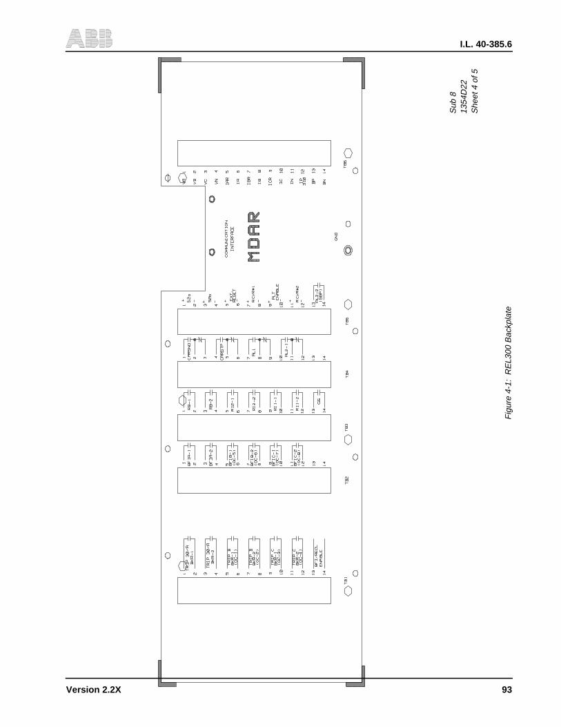
I.L. 40-385.6
Version 2.2X 93
Sub
813
54D
22S
heet
4 o
f 5
Fig
ure
4-1:
RE
L300
Bac
kpla
te

I.L. 40-385.6
94 Version 2.2X
Sub
116
11C
78
Fig
ure
4-2:
RE
L300
Bac
kpla
ne P
C B
oard
Ter
min
als
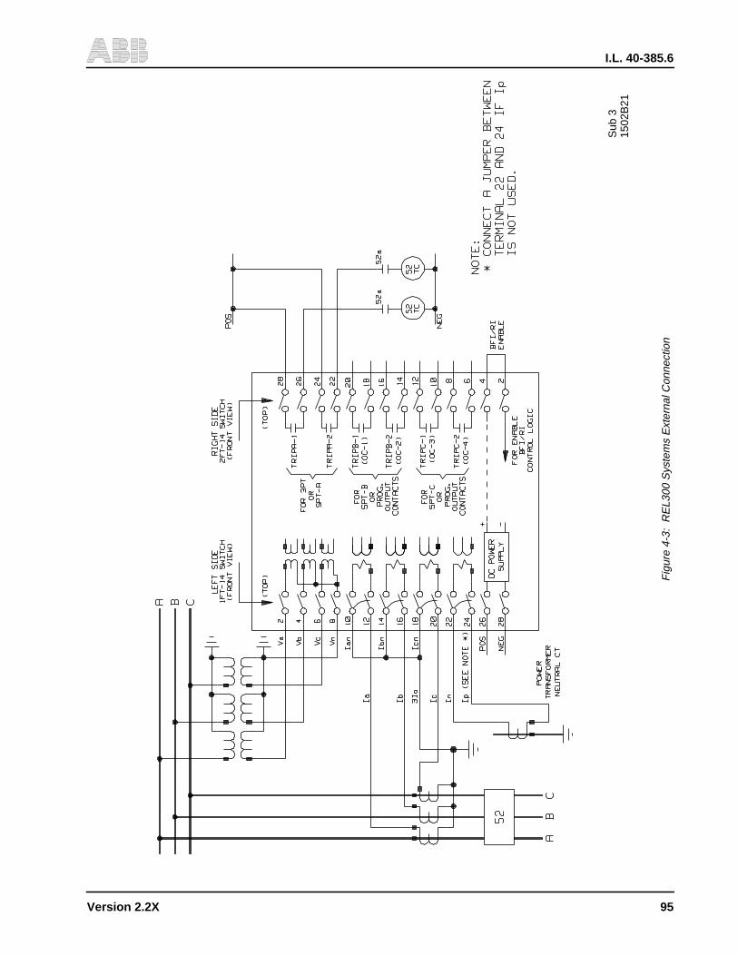
I.L. 40-385.6
Version 2.2X 95
Sub
315
02B
21
Fig
ure
4-3:
RE
L300
Sys
tem
s E
xter
nal C
onne
ctio
n
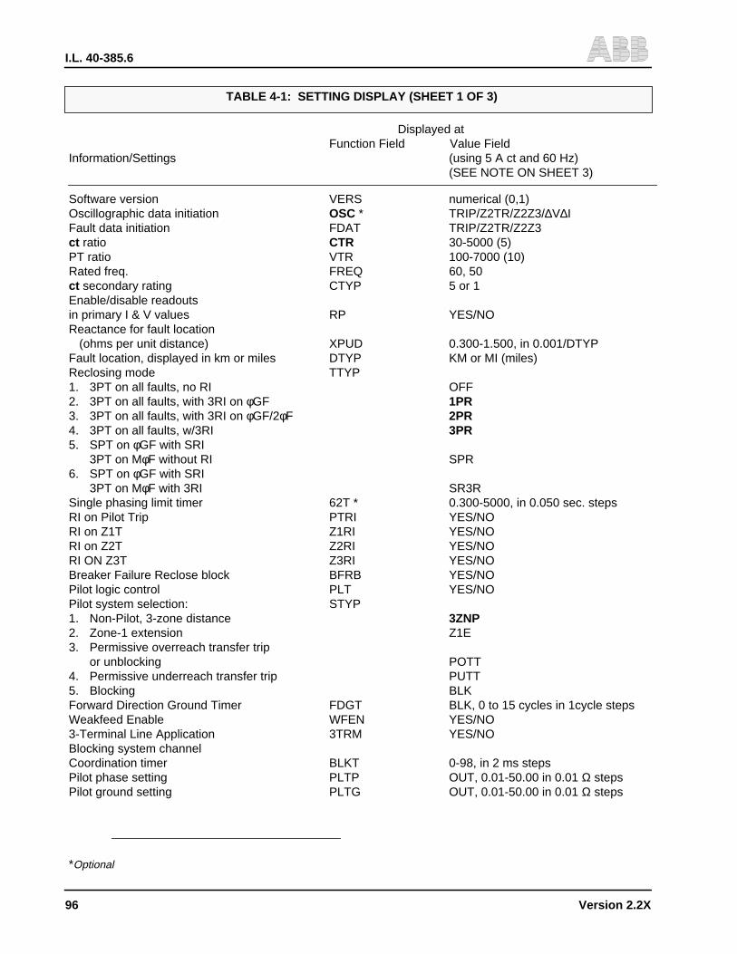
I.L. 40-385.6
96 Version 2.2X
Displayed atFunction Field Value Field
Information/Settings (using 5 A ct and 60 Hz)(SEE NOTE ON SHEET 3)
Software version VERS numerical (0,1)Oscillographic data initiation OSC * TRIP/Z2TR/Z2Z3/∆V∆IFault data initiation FDAT TRIP/Z2TR/Z2Z3ct ratio CTR 30-5000 (5)PT ratio VTR 100-7000 (10)Rated freq. FREQ 60, 50ct secondary rating CTYP 5 or 1Enable/disable readoutsin primary I & V values RP YES/NOReactance for fault location
(ohms per unit distance) XPUD 0.300-1.500, in 0.001/DTYPFault location, displayed in km or miles DTYP KM or MI (miles)Reclosing mode TTYP1. 3PT on all faults, no RI OFF2. 3PT on all faults, with 3RI on φGF 1PR3. 3PT on all faults, with 3RI on φGF/2φF 2PR4. 3PT on all faults, w/3RI 3PR5. SPT on φGF with SRI
3PT on MφF without RI SPR6. SPT on φGF with SRI
3PT on MφF with 3RI SR3RSingle phasing limit timer 62T * 0.300-5000, in 0.050 sec. stepsRI on Pilot Trip PTRI YES/NORI on Z1T Z1RI YES/NORI on Z2T Z2RI YES/NORI ON Z3T Z3RI YES/NOBreaker Failure Reclose block BFRB YES/NOPilot logic control PLT YES/NOPilot system selection: STYP1. Non-Pilot, 3-zone distance 3ZNP2. Zone-1 extension Z1E3. Permissive overreach transfer trip
or unblocking POTT4. Permissive underreach transfer trip PUTT5. Blocking BLKForward Direction Ground Timer FDGT BLK, 0 to 15 cycles in 1cycle stepsWeakfeed Enable WFEN YES/NO3-Terminal Line Application 3TRM YES/NOBlocking system channelCoordination timer BLKT 0-98, in 2 ms stepsPilot phase setting PLTP OUT, 0.01-50.00 in 0.01 Ω stepsPilot ground setting PLTG OUT, 0.01-50.00 in 0.01 Ω steps
*Optional
TABLE 4-1: SETTING DISPLAY (SHEET 1 OF 3)

I.L. 40-385.6
Version 2.2X 97
TABLE 4-1: SETTING DISPLAY (SHEET 2 OF 3)Displayed at
Function Field Value FieldInformation/Settings (using 5 A ct and 60 Hz)
(SEE NOTE ON SHEET 3)
Zone 1 phase unit Z1P OUT, 0.01-50.00 in 0.01 Ω stepsZone 1 ground unit Z1G OUT, 0.01-50.00 in 0.01 Ω stepsZone 1 delay trip timer T1 0-15 cycles in 1 cycle stepsZone 2 phase unit Z2P OUT, 0.01-50.00 in 0.01 Ω stepsZone 2 phase timer T2P BLK, 0.10-2.99, in 0.01 sec. stepsZone 2 ground unit Z2G OUT, 0.01-50.00 in 0.01 Ω stepsZone 2 ground timer T2G BLK, 0.10-2.99, in 0.01 sec. stepsZone 3 phase unit Z3P OUT, 0.10-50.00 in 0.01 Ω stepsZone 3 phase timer T3P BLK, 0.10-9.99 in 0.01 sec. stepsZone 3 ground unit Z3G BLK, 0.01-50, 0.01 Ω stepsZone 3 ground timer T3G BLK, 0.10-9.99 in 0.01 sec. stepsZone 3 direction Z3FR FWD/REVPos. Seq. line impedance angle PANG 0-90, in 1.0 degree stepsZero Seq. line impedance angle GANG 0-90, in 1.0 degree stepsZOL/Z1L ZR 0.1-10.0, in 0.1 stepsLow Voltage unit LV 40-60 in 1.0V (rms) stepsOvercurrent units
Low set phase IL 0.5-10, in 0.1 A stepsMed. set phase IM 0.5-10, in 0.1 A stepsLow set ground IOS 0.5-10, in 0.1 A stepsMed. set ground IOM 0.5-10, in 0.1 A stepsHigh set phase ITP OUT, 2-150.0, 0.5 A stepsHigh set ground ITG OUT, 2-150.0, 0.5 A steps
Out-of-step block OSB YES/NOOSB override timer OSOT 400-4000 in 16 ms stepsOSB inner blinder RT 1.00-15.00, in 0.10 Ω stepsOSB outer blinder RU 3.00-15.00, in 0.10 Ω stepsDirectional overcurrent, zeroor negative sequence DIRU ZSEQ/NSEQ/DUALDirectional overcurrentground backup time curve family GBCV OUT, CO2,5,6,7,8,9,11Ground backup pick-up GBPU 0.5-4.0, in 0.1 A stepsGround backup time curves within family GTC 1-63, in 1.0 stepsChoice of directional or non-directional ground backup GDIR YES/NO
* Optional
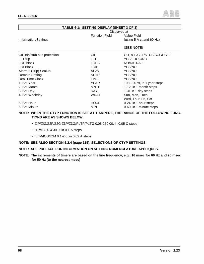
I.L. 40-385.6
98 Version 2.2X
TABLE 4-1: SETTING DISPLAY (SHEET 3 OF 3)Displayed at
Function Field Value FieldInformation/Settings (using 5 A ct and 60 Hz)
(SEE NOTE)
CIF trip/stub bus protection CIF OUT/CF/CFT/STUB/SCF/SCFTLLT trip LLT YES/FDOG/NOLOP block LOPB NO/DIST/ALLLOI Block LOIB YES/NOAlarm 2 (Trip) Seal-In AL2S YES/NORemote Setting SETR YES/NOReal Time Clock TIME YES/NO1. Set Year YEAR 1980-2079, in 1 year steps2. Set Month MNTH 1-12, in 1 month steps3. Set Day DAY 1-31 in 1 day steps4. Set Weekday WDAY Sun, Mon, Tues,
Wed, Thur, Fri, Sat5. Set Hour HOUR 0-24, in 1 hour steps6. Set Minute MIN 0-60, in 1 minute steps
NOTE: WHEN THE CTYP FUNCTION IS SET AT 1 AMPERE, THE RANGE OF THE FOLLOWING FUNC-TIONS ARE AS SHOWN BELOW:
• ZIP/ZIG/Z2P/Z2G Z3P/Z3G/PLTP/PLTG 0.05-250.00, in 0.05 Ω steps
• ITP/ITG 0.4-30.0, in 0.1 A steps
• IL/IM/IOS/IOM 0.1-2.0, in 0.02 A steps
NOTE: SEE ALSO SECTION 5.2.4 (page 115), SELECTIONS OF CTYP SETTINGS.
NOTE: SEE PREFACE FOR INFORMATION ON SETTING NOMENCLATURE APPLIQUES.
NOTE: The increments of timers are based on the line frequency, e.g., 16 msec for 60 Hz and 20 msecfor 50 Hz (to the nearest msec)

I.L. 40-385.6
Version 2.2X 99
TABLE 4-2: METERING DISPLAYDisplayed at
Information Function Field Value Field
Phase A current (mag.) IA numerical, A (X.X)Phase A current (ang.) ∠IA deg. (X.X)Phase A voltage (mag.) VAG numerical, v (XX.X)Phase A voltage (ang.) ∠VAG deg. (XX)
Phase B current (mag.) IB (0.0)Phase B current (ang.) ∠IB (0)Phase B voltage (mag.) VBG (0.0)Phase B voltage (deg.) ∠VBG (0)
Phase C current (mag.) IC (0.0)Phase C current (ang.) ∠IC (0)Phase C voltage (mag.) VCG (0.0)Phase C voltage (ang.) ∠VCG (0)Month / Day DATE numerical (00.00)Hour / Minute TIME numerical (00.00)
Local/Remote Setting SET LOC/REM/BOTHCarrier Receive -1 RX1 YES/NOCarrier Receive -2 RX2 YES/NOLOP indication LOP YES/NOLOI indication LOI YES/NOOut-of-Step Block OSB YES/NORotation of Phase Sequence ROT JABC/JACB
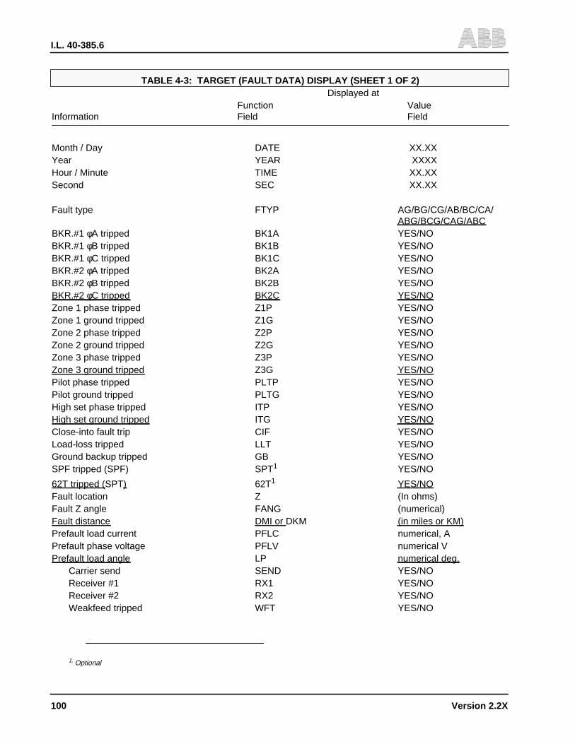
I.L. 40-385.6
100 Version 2.2X
TABLE 4-3: TARGET (FAULT DATA) DISPLAY (SHEET 1 OF 2)Displayed at
Function ValueInformation Field Field
Month / Day DATE XX.XXYear YEAR XXXXHour / Minute TIME XX.XXSecond SEC XX.XX
Fault type FTYP AG/BG/CG/AB/BC/CA/ABG/BCG/CAG/ABC
BKR.#1 φA tripped BK1A YES/NOBKR.#1 φB tripped BK1B YES/NOBKR.#1 φC tripped BK1C YES/NOBKR.#2 φA tripped BK2A YES/NOBKR.#2 φB tripped BK2B YES/NOBKR.#2 φC tripped BK2C YES/NOZone 1 phase tripped Z1P YES/NOZone 1 ground tripped Z1G YES/NOZone 2 phase tripped Z2P YES/NOZone 2 ground tripped Z2G YES/NOZone 3 phase tripped Z3P YES/NOZone 3 ground tripped Z3G YES/NOPilot phase tripped PLTP YES/NOPilot ground tripped PLTG YES/NOHigh set phase tripped ITP YES/NOHigh set ground tripped ITG YES/NOClose-into fault trip CIF YES/NOLoad-loss tripped LLT YES/NOGround backup tripped GB YES/NOSPF tripped (SPF) SPT1 YES/NO
62T tripped (SPT) 62T1 YES/NOFault location Z (In ohms)Fault Z angle FANG (numerical)Fault distance DMI or DKM (in miles or KM)Prefault load current PFLC numerical, APrefault phase voltage PFLV numerical VPrefault load angle LP numerical deg.
Carrier send SEND YES/NOReceiver #1 RX1 YES/NOReceiver #2 RX2 YES/NOWeakfeed tripped WFT YES/NO
1. Optional

I.L. 40-385.6
Version 2.2X 101
Displayed at
Function Value
Information Field Field
Fault type FTYP AG/BG/CB/AB/BC/CA
ABG/BCG/CAG/ABC
Fault voltage VA (mag.) VPA numerical, V
(ang.) ∠VPA numerical deg.
Fault voltage VB (mag.) VPB numerical V
(ang.) ∠VPB numerical deg.
Fault voltage VC (mag.) VPC numerical V
(ang.) ∠VPC numerical deg.
Fault voltage 3V0 (mag.) 3VO numerical V
(ang.) ∠3VO numerical deg.
Fault voltage IA (mag.) IPA numerical A
(deg.) ∠IPA numerical deg.
Fault voltage IB (mag.) IPB numerical A
(deg.) ∠IPB numerical deg.
Fault voltage IC (mag.) IPC numerical A
(deg.) ∠IPC numerical deg.
Fault Current 3I0 (mag) 3I0 numerical A
(deg.) ∠3I0 numerical deg.
Pol. current IP (mag.) IP numerical A
(deg.) ∠IP numerical deg.
Month/Day DATE XX.XX
Year YEAR 1980-2079
Hour/Minute TIME XX.XX
Second SEC XX.XX
TABLE 4-3: TARGET (FAULT DATA) DISPLAY (SHEET 2 OF 2)
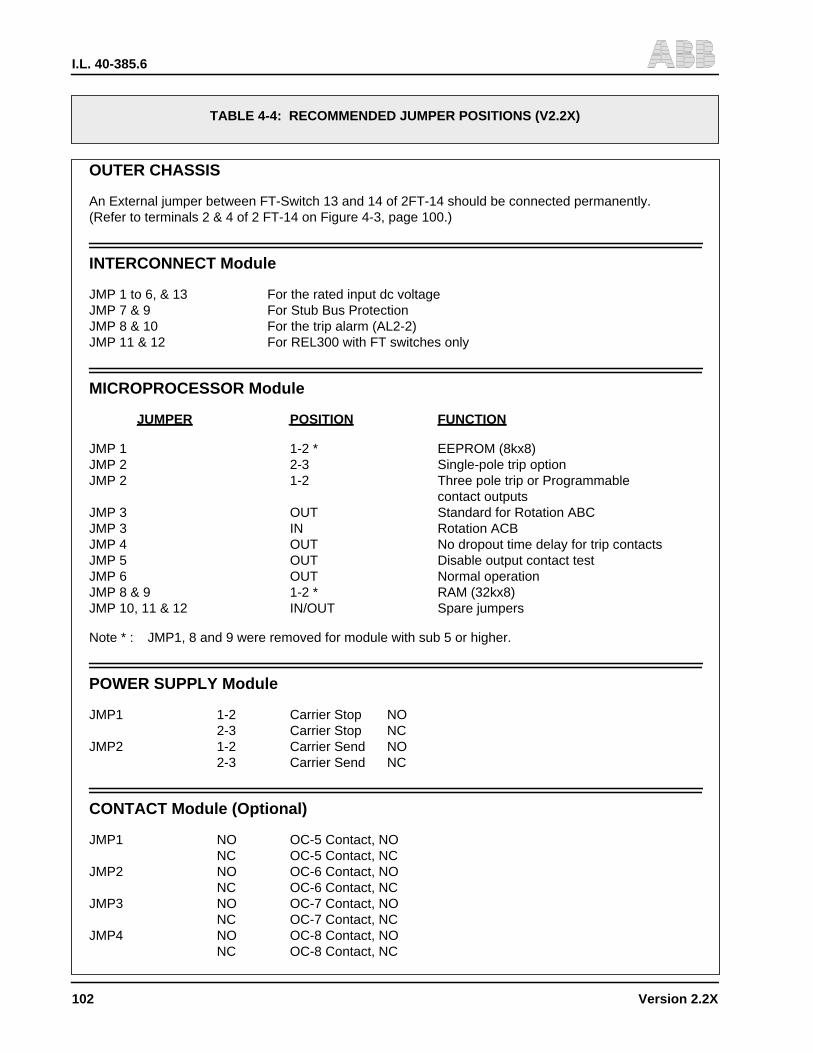
I.L. 40-385.6
102 Version 2.2X
TABLE 4-4: RECOMMENDED JUMPER POSITIONS (V2.2X)
OUTER CHASSIS
An External jumper between FT-Switch 13 and 14 of 2FT-14 should be connected permanently.(Refer to terminals 2 & 4 of 2 FT-14 on Figure 4-3, page 100.)
INTERCONNECT Module
JMP 1 to 6, & 13 For the rated input dc voltageJMP 7 & 9 For Stub Bus ProtectionJMP 8 & 10 For the trip alarm (AL2-2)JMP 11 & 12 For REL300 with FT switches only
MICROPROCESSOR Module
JUMPER POSITION FUNCTION
JMP 1 1-2 * EEPROM (8kx8)JMP 2 2-3 Single-pole trip optionJMP 2 1-2 Three pole trip or Programmable
contact outputsJMP 3 OUT Standard for Rotation ABCJMP 3 IN Rotation ACBJMP 4 OUT No dropout time delay for trip contactsJMP 5 OUT Disable output contact testJMP 6 OUT Normal operationJMP 8 & 9 1-2 * RAM (32kx8)JMP 10, 11 & 12 IN/OUT Spare jumpers
Note * : JMP1, 8 and 9 were removed for module with sub 5 or higher.
POWER SUPPLY Module
JMP1 1-2 Carrier Stop NO2-3 Carrier Stop NC
JMP2 1-2 Carrier Send NO2-3 Carrier Send NC
CONTACT Module (Optional)
JMP1 NO OC-5 Contact, NONC OC-5 Contact, NC
JMP2 NO OC-6 Contact, NONC OC-6 Contact, NC
JMP3 NO OC-7 Contact, NONC OC-7 Contact, NC
JMP4 NO OC-8 Contact, NONC OC-8 Contact, NC
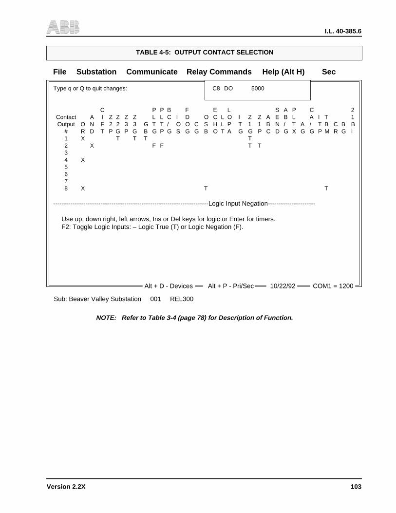
I.L. 40-385.6
Version 2.2X 10³
File Substation Communicate Relay Commands Help (Alt H) Sec
Type q or Q to quit changes: C8 DO 5000
C P P B F E L S A P C 2Contact A I Z Z Z Z L L C I D O C L O I Z Z A E B L A I T 1Output O N F 2 2 3 3 G T T / O O C S H L P T 1 1 B N / T A / T B C B B
# R D T P G P G B G P G S G G B O T A G G P C D G X G G P M R G I1 X T T T T2 X F F T T34 X5678 X T T
------------------------------------------------------------------------Logic Input Negation----------------------
Use up, down right, left arrows, Ins or Del keys for logic or Enter for timers.F2: Toggle Logic Inputs: – Logic True (T) or Logic Negation (F).
TABLE 4-5: OUTPUT CONTACT SELECTION
Alt + D - Devices Alt + P - Pri/Sec 10/22/92 COM1 = 1200
Sub: Beaver Valley Substation 001 REL300
NOTE: Refer to Table 3-4 (page 78) for Description of Function.
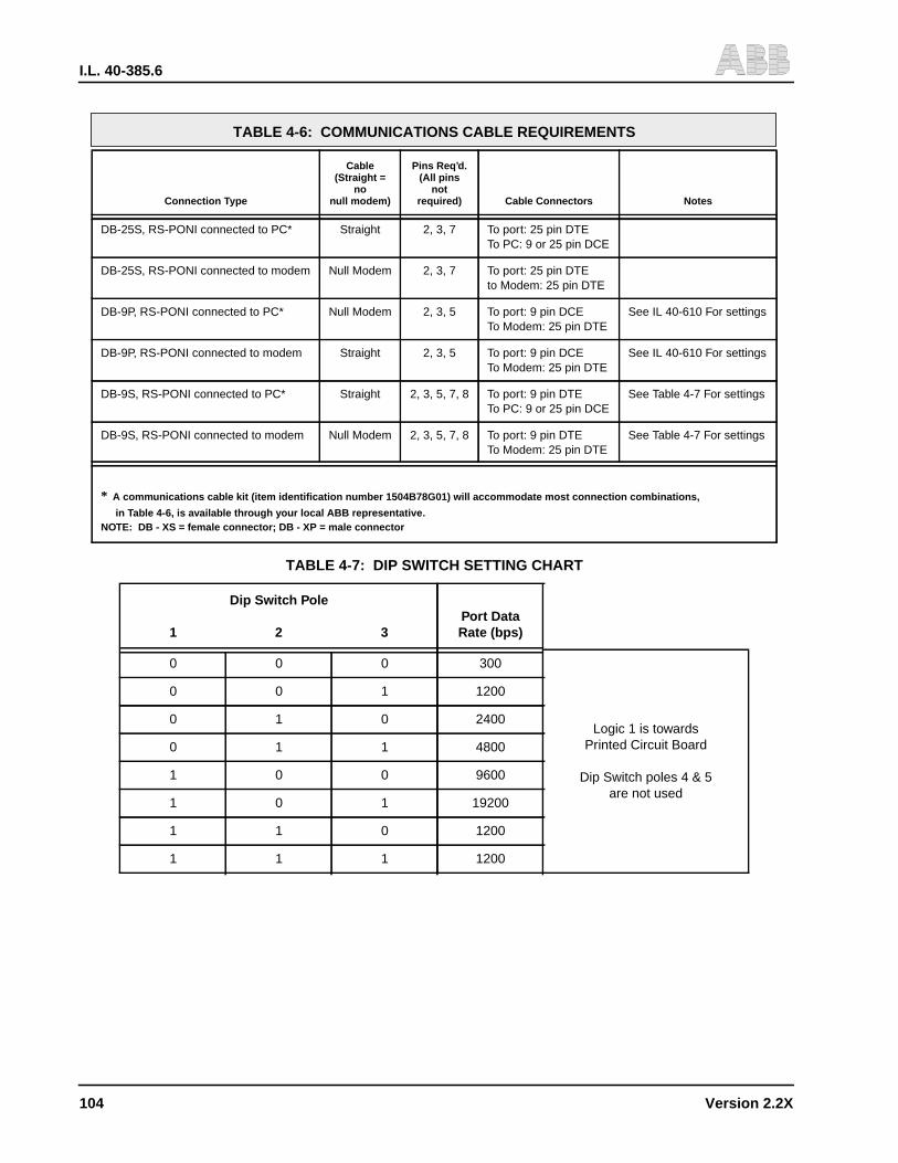
I.L. 40-385.6
104 Version 2.2X
TABLE 4-6: COMMUNICATIONS CABLE REQUIREMENTS
Connection Type
Cable(Straight =
nonull modem)
Pins Req’d.(All pins
notrequired) Cable Connectors Notes
DB-25S, RS-PONI connected to PC* Straight 2, 3, 7 To port: 25 pin DTETo PC: 9 or 25 pin DCE
DB-25S, RS-PONI connected to modem Null Modem 2, 3, 7 To port: 25 pin DTEto Modem: 25 pin DTE
DB-9P, RS-PONI connected to PC* Null Modem 2, 3, 5 To port: 9 pin DCETo Modem: 25 pin DTE
See IL 40-610 For settings
DB-9P, RS-PONI connected to modem Straight 2, 3, 5 To port: 9 pin DCETo Modem: 25 pin DTE
See IL 40-610 For settings
DB-9S, RS-PONI connected to PC* Straight 2, 3, 5, 7, 8 To port: 9 pin DTETo PC: 9 or 25 pin DCE
See Table 4-7 For settings
DB-9S, RS-PONI connected to modem Null Modem 2, 3, 5, 7, 8 To port: 9 pin DTETo Modem: 25 pin DTE
See Table 4-7 For settings
* A communications cable kit (item identification number 1504B78G01) will accommodate most connection combinations,
in Table 4-6, is available through your local ABB representative.NOTE: DB - XS = female connector; DB - XP = male connector
TABLE 4-7: DIP SWITCH SETTING CHART
Dip Switch Pole
1 2 3Port DataRate (bps)
0 0 0 300
Logic 1 is towardsPrinted Circuit Board
Dip Switch poles 4 & 5are not used
0 0 1 1200
0 1 0 2400
0 1 1 4800
1 0 0 9600
1 0 1 19200
1 1 0 1200
1 1 1 1200

I.L. 40-385.6
Version 2.2X 10⁵
Section 5. SETTING CALCULATIONS
! WARNING
Check jumper #3 on the Microprocessor module for phase sequence rotation ABC orACB. Remove jumper #3 for system ABC rotation. Refer to Section 1.8 (page 7) for ACBsystem.
5.1 CALCULATION OF REL300 SETTINGS
The following REL300 setting calculations correspond to the setting categories in the Installa-tion Section 4 (begining on page 79). Assume that the protected line has the following data:
• 18.27 miles
• Line reactance 0.8 ohms/mile
• 69 kV, 60 cycles
• Positive and negative sequence impedances:
ZIL(Pri) = Z2L(Pri) = 15∠77° ohms
• Zero sequence impedance:Z0L(pri) = 50∠73° ohms
• Current Transformer Ratio (CTR):RC = 1200/5 = 240 (Set CTR = 240)
• Voltage Transformer Ratio (VTR):RV = 600/1 = 600 (Set VTR = 600)
• Relay secondary ohmic impedances are:
Z = Zpri x RC/RV
Z1L = Z2L = 15∠77° x 240/600 = 6∠77° ohms
Z0L = 50∠73° x 240/600 = 20∠73° ohms
5.1.1 Ratio of Zero and Positive Sequence Impedances (ZR)
ZR = Z0L/Z1L = 20/6 = 3.33
then REL300 will automatically calculate the zero sequence current compensation factor (k0)by using the value of ZR, PANG, GANG and equation (1) in section 3.2.1( page 26), i.e.,
ko = (Z0L -Z1L)/Z1L = ZR ∠(GANG-PANG)-1
I.L. 40-385.6
106 Version 2.2X
NOTE: The setting range of ZOL/ZIL has been expanded 0.1 - 7.0 to 0.1 - 10. Also the settingranges of Positive sequence line impedance angle (PANG), Zero sequence line imped-ance angle (GANG), have been expanded from 40˚ - 90˚ to 10˚ - 90˚ as well. These chang-es were made to accommodate a wide variety of system components andconfigurations. However, the selection of each setting has to be carefully considered ifthe maximum fault current is 200 Amperes (secondary or above).
If the maximum fault current is 200 amperes (secondary) the following restrictions mustbe observed:
ZOL/ZIL less than or equal to 7.5The setting difference of |PANG| - |GANG| = 50˚ or less
If the maximum fault current is less than 200 Amperes (secondary) these restrictions donot apply.
5.1.2 Zone 1 Distance Unit Settings
A setting of 80% of the line impedance for zone-1 reach is recommended, thus the Zone-1phase and ground reach should be:
Z1P = 6 x 0.8 = 4.8 andZ1G = 6 x 0.8 = 4.8
NOTE: Z1P and Z1G can be set for different values if the application is required. Refer to Sec-tion 6.1.1.3 (page 122), Step 10 for calculation and example.
As stated above, start with a setting of 80% of the line impedance for the zone-1 reach setting.Adjustment of the zone-1 reach (line percentage) should be considered if any of the followingare true:
1. If the calculated zone-1 impedance is 0.5 ohms (secondary) or less, the line percentageused for the calculation should be 70-75%.
2. If the Source Impedance Ratio or SIR, (ratio of positive sequence source impedance topositive sequence line impedance) is in the range of 3-5, line percentage used for the cal-culation should be no more than 75%.
3. Circuit fault impedance angles in the range of 80 degrees produce dc time consonant ofabout one cycle. One cycle time constants result in maximum overreach error of about16%. Hence the line percentage used should be no more than 70 - 75%. If the total faultimpedance angle is greater than 86 degrees, the dc time constant is greater than 2.3cycles, and the overreach error is reduced to 10 percent or less. the same is true if the faultimpedance angle is less than 75 degrees. If system fault impedance angles are known tobe either above 86 degrees or below 75 degrees, the line percentage, used for the zone-1calculation, can be increased by 5 percent. (All angles are based on 60 Hz systems.)
NOTE: The fault impedance angle is fixed and is a measurement of the linecharacteristic, therefore, the fault impedance angle is the angle of currentlooking from the relay into the fault.
4. If CCVT’s, of the low-capacitance type, (e.g. 1960’s vintage PCA-5 and PCA-8 designs) arein use, the line percentage used for the zone-1 calculation, should be 70-75%. Severe sub-sidence-transient related overreach has been noted in cases where low-capacitance

I.L. 40-385.6
Version 2.2X 10⁷
CCVT’s are used in “short time” applications. An alternative to reducing the zone-1 settings,is to introduce a zone-1 time delay (T1) of one or two cycles and using the 80 percent zone-1 reach calculation.
5.1.3 Zone 2 and Pilot Distance Unit Settings
Generally, Zone-2 reach is set for 100% of the protected line plus 50% of the shortest adjacentline, For this example, if the shortest (or only) adjacent line primary impedance is 20 ohms, thenthe Zone-2 reach setting would be:
Z2P = 6 + (20 x 0.5) x 240/600 = 10 andZ2G = 10
The pilot zone distance phase and ground reaches can be set either exactly or nearly equal tothe Zone 2 phase and ground distance reach, which depends on the application. For this ex-ample, set it equal to Zone 2 reach, i.e.,
PLTP = 10 and PLTG = 10
NOTE: Z2P, Z2G, PLTP and PLTG can be set for different values or disabled if the applicationis required.
5.1.4 Zone 3 Distance Unit Settings
Generally, Zone-3 reach is set to underreach of the shortest Zone 2 reach of the adjacent lineoff the remote bus. A practical setting is set for 100% of the protected line plus 100% of theshortest adjacent line off the remote bus. For example, if the shortest Zone 2 reach off the re-mote bus is 25 ohms primary, and infeed effect may increase its impedance by 30%, then theZone 3 reach setting should be:
Z3P = 6 + (25 x 1.3) x 240/600 = 19 andZ3G = 19
NOTE: Z3P and Z3G can be set for different values if the application is required.
5.1.5 Overcurrent Unit Setting
a. The low set phase overcurrent unit is used for supervising the load-loss-trip and CIF func-tions. It should be set higher than the line charging current and below the minimum loadcurrent.
NOTE: It should be set above the maximum tapped load current if applicable.
Assume that the line charging current is negligible for this line section, and the minimumload current is 2.0 A secondary, then the low set phase overcurrent unit setting should be:
IL = 1
I.L. 40-385.6
108 Version 2.2X
b. The medium set phase overcurrent unit is used for supervising the OSB function and all thephase distance units. this unit should be set not to limit the Zone 3 reach, but traditionally,its setting should be set higher than load current.
Assume that 4.5 amperes has no effect to the Zone 3 reach, and the maximum load currentis 4.0 amperes, then the medium set phase overcurrent unit can be set to:
IM = 4.5
c. The low-set ground overcurrent unit is used for supervising the reverse directional overcur-rent ground unit (RDOG) for transient block in pilot system and carrier SEND in Blockingsystem. It should be set as sensitive as possible. A setting of 0.5 amperes is recommended:
IOS = 0.5
d. The medium set ground overcurrent unit is used for supervising the trip of Zone 1, Zone 2and Zone 3 ground distance units (Z1G, Z2G and Z3G), the forward directional overcurrentground unit (FDOG). Generally, it is recommended to be set 2 times the IOS setting.
IOM = 2 x IOS = 1.0
e. The directional high set overcurrent phase and ground units (ITP and ITG) are used for di-rect trip function. The general setting criterion for the instantaneous direct trip unit is:
The unit should be set higher than 1.15 times the maximum fault on the remote bus, wherethe factor of 1.15 is to allow for the transient overreach. For this example, assume that themaximum load is not higher than the maximum forward end zone fault current, and themaximum phase and ground fault currents on the remote bus are 20 and 24 amperes, re-spectively, then the settings of the high-set phase (ITP) and the high-set ground (ITG)should be:
ITP = 20 x 1.15 = 23
ITG = 24 x 1.15 = 27.6
5.1.6 OSB Blinder Settings (RT and RU)
The requirements for setting the blinder units are:
• Inner blinder must be set to accommodate maximum fault resistance for internal 3-phasefault
• Inner blinder should not operate on severe stable swings
• Outer blinder must have adequate separation from inner blinder for fastest out-of-step swingto be acknowledged as an out-of-step condition
• Outer blinder must not operate on load

I.L. 40-385.6
Version 2.2X 10⁹
NOTE: For the setting of OSB = NO, the REL300 will not read the settings of OSOT and RU, however,RT is still used for load restriction.
a. Setting the Inner Blinder (21BI)
If the OSB is used to supervise tripping of the 3φ unit on heavy load current, the inner blind-er 21BI must be set sufficiently far apart to accommodate the maximum fault arc resistance.A reasonable approximation of arc resistance at fault inception is 400 volts per foot. If amaximum ratio of “line voltage per spacing” is 10,000 volts/ft. for a high voltage transmis-sion line, and if a minimum internal 3-phase fault current is calculated as:
Imin. = [E / 1.73(ZA+ZL)]
where ZA is maximum equivalent source impedance, ZL is line impedance and E is line-to-linevoltage.
then Rmax = 400 x FT / Imin.
= 400x1.73(ZA+ZL)/10000
= 0.0693 (ZA+ZL)
Adding a 50% margin to cover the inaccuracies of this expression:
Rmax. = 0.104(ZA+ZL) primary ohms
RS = 0.104(ZA+ZL)RC/RV secondary ohms
Set inner blinder to:
RT = RS x COS (90° - PANG) (1)
This is the minimum permissible inner blinder setting when it is used to provide a restricted triparea for a distance relay.
Another criterion that may be considered is based upon the rule of thumb that stable swingswill not involve an angular separation between generator voltages in excess of 120°. This wouldgive an approximate maximum of:
Zinner = (ZA+ZL+ZB)/ (2x1.73) (2)
= 0.288(ZA+ZL+ZB) primary ohms
Zinner = 0.288(ZA+ZL+ZB)RC/RV secondary ohm
where ZB is the equivalent maximum source impedance at the end of the line away from ZA.
An inner blinder setting between the extremes of equations (1) and (2) may be used. This pro-vides operation for any 3-phase fault with arc resistance, and restraint for any stable swing. Ex-cept in those cases where very fast out-of-step swings are expected, the larger setting can beused.
It will usually be possible to use the minimum inner blinder setting of 1.5 ohms.
I.L. 40-385.6
110 Version 2.2X
b. Setting the Outer Blinder (21BO)
For slow out-of-step swings, a reasonably close placement of outer to inner blinder charac-teristic is possible. The separation must, however, be based on the fastest out-of-step swingexpected. A 50 ms interval is inherent in the out-of-step sensing logic, and the outer blindermust operate 50 ms or more ahead of the inner blinder.
Since the rate of change of the ohmic value manifested to the blinder elements is depen-
dent upon accelerating power and system WR2, it is impossible to generalize. However,based on an inertia constant (H) equal to 3, and the severe assumption of full load rejection,a machine will experience (assuming a uniform acceleration) an angular change in positionof no more than 20° per cycle on the first half slip cycle.
If the inner blinder were set for (0.104ZT), and the very severe 20° per cycle swing rate were
used, the outer blinder should be set for approximately:
Zouter = 0.5 ZT primary ohms (3)
where ZT = ZA + ZB + ZL
This is the minimum setting of the outer blinder for a 20° per cycle swing rate.
For example, if Zinner = 0.104 ZT, Zouter = 0.5 ZT, RT = 1.5
5.1.7 Overcurrent Ground Backup Unit (GB)
The overcurrent ground backup unit GB provides seven sets of curves, which are similar to theCO and MCO curves, for backing up the distance ground on high resistance ground faults. Foursettings (GBCV, GBPU, GTC and GDIR) should be determined for applying this unit.
a. GBCV is the ground backup curve selection. Seven sets of familiar CO curves are provided(C02,5,6,7,8,9 and 11), and are shown in Figures 2-1 thru 2-7 (starting at page 16). The se-lection is based on the application and coordination time. A selection of “OUT” disables theground backup function.
b. GBPU is the current level setting. Its range is 0.5 to 4.0 amperes in 0.5 steps. In general, thecurrent level setting criterion is:
(IFmin /2) > Setting level > 2 x (Max.residual load, 3I0)
where IFmin = Minimum ground fault currentfor a fault two buses away
For better sensitivity, GBPU should be set at 0.5 amperes, this would be adequate for most ofthe application.
ZouterZinner------------------
0.5000.104------------- 4.8= =
ZoutterZinner--------------------
RURT-------- 4.8= =
RU 4.8 1.5× 7.2= =
I.L. 40-385.6
Version 2.2X 111
c. GTC is the time delay setting of the GB unit. As shown in Figures 2-1 thru 2-7 (starting atpage 16), it has 63 setting selections, from 1 to 63 in 1.0 steps. In general, the time delaysetting should be coordinated with any protective device downstream of the line section.
The following equation can be used to calculate the trip time for all CO curves from CO-2 thruCO-11 :
T (sec) = (for 3I0 ≥ 1.5) T(sec) = (for 1<3I0< 1.5)
Where 3I0 =
GBPU = Pickup current setting (0.5 to 4.0A).
GTC = Time curve dial setting (1 to 63).
T0, K, C, P and R are constants, and are shown in Table 5-3 (page 120).
d. GDIR is the setting for directional control selection. The GB unit will become a directionaltorque control overcurrent ground unit if GDIR is set at YES.
e. DIRU controls the setting of the directional polarizing ground overcurrent unit. It has 3selections:
ZSEQ — Zero sequence voltage polarization only.
DUAL — Both zero sequence voltage and current polarizations.
NSEQ — Negative sequence voltage and current operated.
Taking the CO-8 curve set as an example (see Figure 2-5, page 20), assuming that the maxi-mum 3Io of unbalanced load is 0.2A, the minimum ground fault current for a fault two busesaway is 10A, and 0.7 seconds is required for coordination with current of 20 times the GBPUsetting, then the settings of the GB function should be as shown below:
10/2 > GB > 2 x 0.2 set GBPU = 0.5
Using the curve in Figure 2-1 (page 16), for 0.7 seconds at 20 times the GBPU setting, GTCshould be set to 24.
• Set GBCV = C0-8 and
• Set GDIR = YES if directional control is required.
• Set DIRU = ZSEQ
5.1.8 Timer Settings
a. Zone-2 timer (T2) setting should be coordinated with the Zone-1 and other high-speed tripunits on the adjacent line terminal. Coordination Time Interval (CTI) of 0.3 to 0.5 secondsis recommended. For example, if T2 of 0.4 seconds is used, then the phase and groundZone-2 timers should be set as follows:
T2P = 0.4 and T2G = 0.4
T0K
3I 0 C–( )P--------------------------+
GTC24 000,------------------× R
3I 0 1–( )----------------------GTC
24 000,------------------×
I F
GBPU-----------------
I.L. 40-385.6
112 Version 2.2X
NOTE: T2P and T2G are separate timers; they can be set at different time settings.
b. Zone-3 timer (T3) settings would be similar to the above. For example, if T3 of 0.8 secondsis required, then the phase and ground Zone-3 timer should be set as follows:
T3P = 0.8 and T3G = 0.8
NOTE: T3P and T3G are separate timers; they can be set at a different time settings.
c. For out-of-step block (OSB), if applied, the OSB override timer setting (OSOT) is deter-mined by the power system operation. Its range is 400 to 4000 ms, in 16 ms steps. Forexample, set REL300 OSOT = 500 if OSB override time of 500 ms is required.
d. For single-pole trip application only, the single phasing limit timer setting (62T) is for pre-venting thermal damage to rotating machines, due to the I2 component during single
phasing. Its range is 300 to 5000 ms. in 50 ms steps. The setting should be based on the
poorest (I2)2t constant of the machines in service. For example, set REL300 62T = 1550, if
3PT is required before 1.55 seconds and after one pole has been open and the breakerdoes not or cannot reclose.
e. For the blocking system only, the channel coordination timer setting (BLKT) is based on thefollowing application criteria:
BLKT > (Slowest remote carrier start time + channel time + margin) - (the fastest local 21P/21NP pickup time)
Where channel time includes the transmitter and receiver times, and the times which occurbetween these devices, e.g., wave propagation, interfacing relays, etc.
For REL300:fastest 21P/21NP pickup time = 14 msslowest carrier start time = 4 mssuggested margin time = 2 ms
For example, the REL300 channel coordination timer should be determined as shown be-low, if the channel time is 3 ms.
BLKT = (4 + 3 + 2) - 14= -5
i.e., set BLKT= 0
5.2 SELECTION OF REL300 SETTINGS
The following settings are determined by the application. They do not require calculation.
5.2.1 The OSC Setting
For selecting one of the 4 ways (TRIP/Z2TR/Z2Z3/∆I∆V) to initiate the oscillographic data tak-en, where:
TRIP — start data taken only if trip action occurs.
Z2TR — start data taken if Zone 2 units pick up, or any trip action occurs.
I.L. 40-385.6
Version 2.2X 113
Z2Z3 — start data taken if Zone 2 or Zone 3 units pick up, or any trip action occurs.
∆I∆V — start data taken if ∆I, ∆V, Zone 2 or Zone 3 units pick up, or any trip action occurs.
NOTE: The setting of ∆I, ∆V, for OSC is not recommended.
5.2.2 The FDAT Setting
For selecting one of the 3 ways (TRIP/Z2TR/Z2Z3) to initiate the fault data taken, where:
TRIP — start to store fault data only if trip action occurs.
Z2TR — start to store fault data if Zone 2 units pick up or any trip action occurs.
Z2Z3 — start to store fault data if Zone 2 or Zone 3 units pick up or any trip action occurs.
5.2.3 The Current Transformer Ratio Setting (CTR)
Used for the load current monitoring, if it is selected to be displayed in primary amperes. It hasno effect on the protective relaying system. For this example, set CTR = 240.
5.2.4 The Voltage Transformer Ratio Setting (VTR)
Used for the system voltage monitoring, if it is selected to be displayed in primary volts. It hasno effect on the protective relaying system. For this example, set VTR = 600.
5.2.5 The Frequency Setting (FREQ)
FREQ should be selected to match the power system operating frequency. For example, selectFREQ = 60 if the power system operating frequency is 60 Hertz.
5.2.6 The Current Transformer Type Setting (CTYP)
CTYP provides the flexibility for 5 Amp or 1 Amp rated current transformer selection. For ex-ample, select and set CTYP = 5 if a 5 Amp current transformer is used.
The setting of CTYP affects all the distance unit and overcurrent unit setting ranges. The rang-es will be automatically changed as listed in Table 5-1(page 119).
5.2.7 THe Read Primary Setting (RP)
The RP should be set at YES if all the monitoring ac voltages and currents are selected to bedisplayed in primary KV and KA values, respectively.
5.2.8 Ohms Per Unit Distance Of The Line Primary Reactance Setting (XPUD)
XPUD is the multiplier for fault distance display. It has a range of 0.3 to 1.5 in 0.001 steps. Inthis example, the line primary reactance is 0.8 ohms/mile; set XPUD = 0.8.
The fault distance calculation is as follows:
DMIVTRCTR-----------
ZS FAN∠sin×XPUD
--------------------------------------×=
I.L. 40-385.6
114 Version 2.2X
Where ZS is the secondary impedance magnitude, and FANG is the fault angle.
5.2.9 The Setting of DTYP
The setting of DTYP (distance type DKM &DMI) has a selection of MILE and KM. It should beselected to match with the setting of XPUD. For this example, select DTYP = MILE.
5.2.10 The Setting of TTYP
The setting of TTYP is for selecting the reclosing mode in single pole trip applications (if appli-cable). It has six selecting positions (OFF, 1PR, 2PR, 3PR, SPR, and SR3R). Refer to theguidelines for reclosing mode programming for the TTYP setting selection.
5.2.11 For An SPT Application
For an SPT application set the 62T single phasing limit timer from 300 to 5000 ms in 50 ms
steps. The setting is based on the generator’s (I2) 2t performance. LV should be set between85% and 90% of the rated line-to-neutral voltage.
5.2.12 The Settings Of PTRI, Z1RI, Z2RI and Z3RI
The settings of PTRI, Z1RI, Z2RI and Z3RI, provide the selectivity for Pilot RI (reclosing initia-tion), Zone-1 RI, Zone 2-RI and Zone 3 RI, respectively. For the non-pilot system application,set Z1RI, Z2RI and/or Z3RI to YES, if RI is required when the particular distance zone operates.For the pilot reclosing, Z1RI should be set to “YES”.
5.2.13 For A Pilot System
For a pilot system, set BFRB to YES if RB on the breaker failure squelch feature is required.
5.2.14 The Setting Of PLT
The setting of PLT (pilot) combines with the signal of Pilot Enable (on the backplane panel) andcontrols the operation of pilot and reclosing initiation. The absence of either signal will:
• disable the pilot system
• block the RI2 output, and
• allow an RI1 output for a non-pilot system.
The PLT can be set either locally from the front panel or, remotely, via the communication chan-nel.
5.2.15 The STYP
The STYP (system type) selects the desired relaying system for the application. It has two se-lections: 3ZNP (3 zone non-pilot) and Z1E (Zone 1 extension) in the non-pilot REL300. Thereare five selections: 3ZNP, Z1E, POTT (permissive overreach transfer trip or unblocking), PUTT(permissive underreach transfer trip) and BLK (blocking) in the pilot REL300. It should be setto the desired selection.
I.L. 40-385.6
Version 2.2X 115
5.2.16 Pilot REL300 Only
For the pilot REL300 only, the WFEN (weakfeed enable) selection should be set to YES for theweakfeed terminal, if applicable.
5.2.17 Permissive Pilot REL300 Only
For permissive pilot REL300 only, the 3TRM (3 terminals) setting should be selected to YESfor all of the POTT/PUTT three terminals that apply, but for the BLK system the “YES” or “NO”makes no difference. Refer to section 3.21 (page 49) for the detailed information.
5.2.18 Application of POTT/BLK Systems
For application of POTT/BLK systems, the transient block logic is always in the POTT/BLK sys-tem, but it is initiated by the reverse looking units. The Z3FR setting should be set to “YES” andZ3P, Z3G should be set to 100% of the line impedance.
5.2.19 The FDGT (FDOG Trip Delay Timer)
The FDGT (FDOG trip delay timer) can be set from 0 to 15 cycles or block (BLK) as desired. Itis recommended to set to 3 cycles or longer. Refer to Section 3.9 (page 47) for the detailedFDGT information.
5.2.20 Distance/overcurrent Units
Distance/overcurrent units can be disabled if required by the application. The following dis-tance/overcurrent units can be disabled by setting the unit to OUT:
a. List of units which can be disabled:
PLTP, PLTG, Z1P, Z2P, Z2G, Z3P, Z3G, ITP, ITG and GB.
b. Procedure to disable the unit:
5.2.20.1 Switch REL300 to the setting mode, scrolling the function field to the proper function Thenset the unit to OUT via the value field.
5.2.20.2 Set T1 up to 15 cycles if Zone 1 delay trip is required.
5.2.20.3 The T2P, T2G, T3P and/or T3G timer functions can be disabled, if desired, by setting the timer toBLK.
5.2.20.4 The Zone 3 distance units (Z3P and Z3G) can be selected to reach forward-looking or reverse-looking by setting the Z3FR (Zone 3 forward or reverse) to FWD or REV. For pilot application,Z3FR must be set to REV.
5.2.20.5 Set the positive sequence impedance angle (PANG) value based on the positive sequence lineimpedance angle. This setting affects the performance of the distance units.
5.2.20.6 Set the zero sequence impedance angle (GANG) value based on the zero sequence lineimpedance angle. This setting affects the performance of the distance units.
5.2.20.7 Set the ZR value based on the absolute value of the ratio of the line impedances (ZOL/Z1L).
NOTE: The settings of PANG and GANG have been expanded from 40-90 to 0-90 degrees andthe ZR setting has been changed form 0.1-7.0 to 0.1-10.0 for underground cable appli-
I.L. 40-385.6
116 Version 2.2X
cation. The setting rule of PANG, GANG and ZR must be followed: if the setting differ-ence of PANG and GANG is greater than 50 degrees OR the ZR setting is greater than7.0, the operating range of the maximum fault current should be limited to 200 am-peres; otherwise, the microcontroller may give an un-predicted result.
5.2.20.8 The LV units are used in CIFT, SPT and weakfeed logic in the REL300. They should normally beset to 40 volts unless a higher setting is required for more sensitive applications. Refer to Section5.2.11 (page 116) for the SPT application.
5.2.20.9 The polarizing approach for the directional ground overcurrent unit is controlled by the setting ofDIRU. It has 3 selections:
ZSEQ – Voltage polarization only.
DUAL – Both voltage and current polarization.
NSEQ – Negative sequence voltage and current polarization.
5.2.20.10 Set GDIR to YES if directional control is required for the GB function.
5.2.20.11 Based on the requirements , set Close-Into-Fault (CIF) and stub-bus protection functions, by se-lecting the value field (OUT/CT/CFT/STUB/SCF/SCFT) of CIF, where:
OUT – No CIFT or SBP selected
CF – Standard CIFT, without timer; No SBP
CFT – Modified CIFT, with timer; No SBP
STUB – SBP logic; No CIFT
SCF – SBP plus standard CIFT
SCFT – SBP plus modified CIFT
Refer to Section 3.4.7 (page 32) for the application of CIF with Timer (200/0).
5.2.20.12 Set LLT (Load-Loss Trip) to YES, FDOG or NO required by the system, where:
5.2.20.13 YES–LLT trip with Z2 supervision.
5.2.20.14 FDOG–LLT trip with both Z2 and FDOG supervision.
5.2.20.15 NO–LT trip function is not used.
5.2.20.16 Refer to Section 3.4.9 for the LLT application.
5.2.20.17 Set LOPB to “DIST” , if loss-of-potential block trip function on Z1, Z2, Z3 and Pilot is required, butthe overcurrent units (ITP, ITG & GB) are still operative. Set LOPB to “ALL”: if loss-of-potential blockall type of trip is required.
5.2.20.18 Set LOIB to YES, if loss-of-current block trip function is required.
5.2.20.19 Set AL2S to YES, if trip alarm seal-in is required. The Reset push-button can be used to reset thesealed AL2.
5.2.20.20 Set the SETR to YES if remote setting is required.
5.2.20.21 Procedure to set the real-time clock:
I.L. 40-385.6
Version 2.2X 117
With REL300 in the “setting” mode, scroll the function field to TIME, and set the value to YES. De-press function push-button RAISE to display YEAR, MNTH (month, DAY, WDAY (week day),HOUR, and MIN (minute), and set the corresponding number via the value field. The REL300 clockwill start at the time when the minute value is entered.
5.3 GUIDANCE FOR RECLOSING INITIATION MODE PROGRAMMING
5.3.1 For System Without SPT System:
a. Select TTYP = OFF or 1PR, or 2PR or 3PR, and
b. Select PLT = NO, and
c. Use the RI2 output contact for the reclosing circuit, and
d. Select one or all of the PTRI, Z1RI, Z2RI and Z3RI to YES, depending on the application.
5.3.2 For System With SPT System:
a. Select TTYP = OFF or 1PR, or 2PR, or 3PR, or SPR or SR3R and
b. Select one or all of the PTRI, Z1RI, Z2RI and Z3RI to YES, depending on the application.
c. Use the RI1 output contact for the SRI reclosing timing circuit, and the RI2 output contactfor the 3RI timing circuit.
The Reclosing Initiation mode will be based on the TTYP setting, as shown in Table 5-2 (page120).
5.4 SELECTION OF PROGRAMMABLE CONTACTS
Thirty signals have been pre-assigned as shown in Table 3-4 (page 78) and Figure 3-33 (page75). The 4 heavy duty contacts (OC1 to OC4) connected to FT switches and 4 standard con-tacts (OC5 to OC8) can be selected from the 30 signals by ANDing or ORing them together.
The selection can only be done from WRELCOM® Communication Channel. Contacts OC4and OC8 provide timers for delay pickup and/or delay dropout. The ranges of timers are 0 to 5seconds in 0.01 second steps.
5.5 BREAKER FAILURE CONTACTS
Refer to the information described in section 3-25 (page 50) for the BFI timing guide.
TABLE 5-1: CURRENT TRANSFORMER SETTINGS
REL300 UNITS At CTYP = 5 At CTYP = 1
Z1P/Z1G/Z2P/Z2G 0.01-50.00, 0.05-250,Z3P/Z3G/PLTP/PLTG in 0.01 Ω steps in 0.05 Ω steps
ITP/ITG 2.0-150.00, 0.4-30.0.in 0.5 A steps in 0.1 A steps
IL/IOS/IOM/IM 0.5-10.0, 0.1-2.0,in 0.1A steps in 0.02 A steps
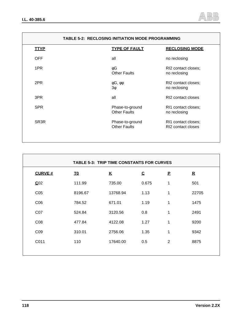
I.L. 40-385.6
118 Version 2.2X
TABLE 5-2: RECLOSING INITIATION MODE PROGRAMMING
TTYP TYPE OF FAULT RECLOSING MODE
OFF all no reclosing
1PR φG RI2 contact closes;Other Faults no reclosing
2PR φG, φφ RI2 contact closes;3φ no reclosing
3PR all RI2 contact closes
SPR Phase-to-ground RI1 contact closes;Other Faults no reclosing
SR3R Phase-to-ground RI1 contact closes;Other Faults RI2 contact closes
TABLE 5-3: TRIP TIME CONSTANTS FOR CURVES
CURVE # T0 K C P R
C02 111.99 735.00 0.675 1 501
C05 8196.67 13768.94 1.13 1 22705
C06 784.52 671.01 1.19 1 1475
C07 524.84 3120.56 0.8 1 2491
C08 477.84 4122.08 1.27 1 9200
C09 310.01 2756.06 1.35 1 9342
C011 110 17640.00 0.5 2 8875
I.L. 40-385.6
Version 2.2X 119
The following kinds and quantities of test equipment are used for the REL300 AcceptanceTests:
• Voltmeter (1)
• Ammeter (1)
• Phase Angle Meter (1)
• Load Bank (2)
• Variac (3)
• Phase Shifter (1)
• Optional Double or Multi-Amp Test System
NOTE: Before turning on the dc power supply, check jumper positions on the Interconnectand Microprocessor modules as shown in Table 4-4 (page 102). Also, refer to this tablefor relay system operation. Use Section 4.1 (page 79) as the guidelines when separat-ing the inner and outer chassis.
! WARNING
Jumper #3 on the Microprocessor module is for the selection of phase sequence rota-tion ABC or ACB. Remove Jumper 3 for system ABC rotation for the following test. Re-fer to Section 1.8 (page 7) for ACB system.
Refer to the NOTE under Table 6-1 (page 141) for 1 amp ct application.
6.1 FULL PERFORMANCE TESTS
Full performance tests explore REL300 responses and characteristics for engineering evalua-tion. They are in two parts: Non-Pilot and Pilot Acceptance Tests.
NOTE: Customers who are familiar with the REL300 performance and characteristics shoulddisregard this section and proceed directly to Section 2 “Maintenance Tests”.
6.1.1 Non-Pilot Performance Tests
To prepare the REL300 relay assembly for Non-Pilot Acceptance Tests, connect the REL300per Figure 6-1 (page 143), Configuration 1.
6.1.1.1 Front Panel Check
Step 1. Turn on rated battery voltage. Check the FREQ setting to match the line frequencyand ct type CTYP. Apply a balanced 3-phase voltage (70 Vac); the Alarm-1 relayshould be energized. (Terminals TB4-7 and -8 should be zero ohms.)
Section 6. FULL PERFORMANCE TESTS (V2.23)

I.L. 40-385.6
120 Version 2.2X
Step 2. Check “RELAY-IN-SERVICE” LED; it should be “ON”.
Step 3. Press “RESET TARGETS” push-button; the green LED (Volts/Amps/Angle) shouldbe “ON”.
Step 4. Press the DISPLAY SELECT push-button, and note that the mode LED cycles thruthe five display modes. Release the push-button so that the SETTINGS mode LEDis “ON”.
Step 5. Refer to the Installation Section, Table 4-1 (page 96 thru page 98, for all possibleREL300 SETTINGS, and set the values in accordance with Table 6-1 (page 141).For Negative Sequence Directional Unit, change DIRU from ZSEQ to NSEQ. Fordual polarizing directional ground unit, change DIRU to DUAL.
Step 6. Press the DISPLAY SELECT push-button to obtain the METERING mode(VOLTS/ AMPS/ANGLE). (Refer to Installation Section, Table 4-2, page 99.)
6.1.1.2 Angle Current and Voltage Input Check
Step 8. Using Figure 6-1 (page 143), Configuration 1, apply three ac voltages of 70 VLNand an ac current of 1A. Adjust phase A current to lag phase A voltage (VAN) by75°.
Step 9. Press FUNCTION RAISE or FUNCTION LOWER push-button. Read input current(IA), input voltage (VAG), and angle (ANG). All values within 5%.
NOTE: Be sure that the RP setting is “NO”. If the RP setting is “YES”, the readings will be theprimary side values.
The angle measurement is for reference only. For I<0.5A, the display of angle will beblocked and show zero degrees.
6.1.1.3 Zone 1 Test/Single-Phase-To-Ground
Step 10. Using Figure 6-1 (page 143), Configuration 1,adjust:
V1N = 30V
V2N = 70V
V3N = 70V
REL300 goes into fault mode processing only after the current detector is enabled. REL300performs the test:
• Phase current (∆IA, ∆IB, or ∆IC) >1.0A peak and 12.5% change
• Voltage ( ∆Van, ∆Vbn, or ∆Vcn ) >7V and 12.5% change with a current change of ∆I>0.5 A
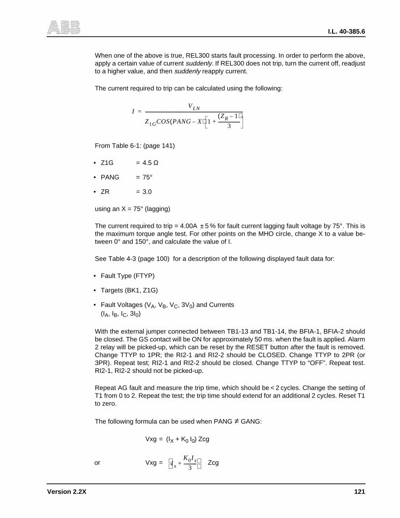
I.L. 40-385.6
Version 2.2X 121
When one of the above is true, REL300 starts fault processing. In order to perform the above,apply a certain value of current suddenly. If REL300 does not trip, turn the current off, readjustto a higher value, and then suddenly reapply current.
The current required to trip can be calculated using the following:
From Table 6-1: (page 141)
• Z1G = 4.5 Ω
• PANG = 75°
• ZR = 3.0
using an X = 75° (lagging)
The current required to trip = 4.00A ± 5 % for fault current lagging fault voltage by 75°. This isthe maximum torque angle test. For other points on the MHO circle, change X to a value be-tween 0° and 150°, and calculate the value of I.
See Table 4-3 (page 100) for a description of the following displayed fault data for:
• Fault Type (FTYP)
• Targets (BK1, Z1G)
• Fault Voltages (VA, VB, VC, 3V0) and Currents(IA, IB, IC, 3I0)
With the external jumper connected between TB1-13 and TB1-14, the BFIA-1, BFIA-2 shouldbe closed. The GS contact will be ON for approximately 50 ms. when the fault is applied. Alarm2 relay will be picked-up, which can be reset by the RESET button after the fault is removed.Change TTYP to 1PR; the RI2-1 and RI2-2 should be CLOSED. Change TTYP to 2PR (or3PR). Repeat test; RI2-1 and RI2-2 should be closed. Change TTYP to “OFF”. Repeat test.RI2-1, RI2-2 should not be picked-up.
Repeat AG fault and measure the trip time, which should be < 2 cycles. Change the setting ofT1 from 0 to 2. Repeat the test; the trip time should extend for an additional 2 cycles. Reset T1to zero.
The following formula can be used when PANG ≠ GANG:
Vxg = (IX + K0 I0) Zcg
or Vxg = Zcg
IVLN
Z1GCOS PANG X–( ) 1ZR 1–( )
3--------------------+
------------------------------------------------------------------------------------------=
I x
K0I x
3------------+
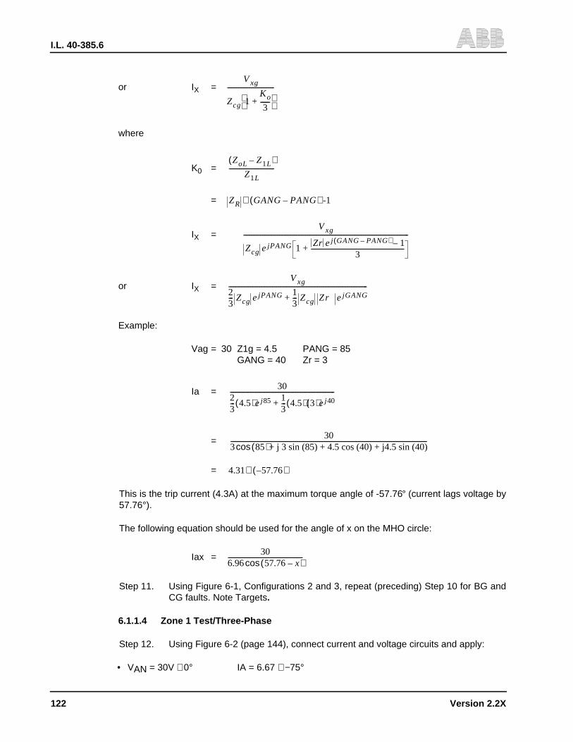
I.L. 40-385.6
122 Version 2.2X
or IX =
where
K0 =
=
IX =
or IX =
Example:
Vag = 30 Z1g = 4.5 PANG = 85GANG = 40 Zr = 3
Ia =
=
=
This is the trip current (4.3A) at the maximum torque angle of -57.76° (current lags voltage by57.76°).
The following equation should be used for the angle of x on the MHO circle:
Iax =
Step 11. Using Figure 6-1, Configurations 2 and 3, repeat (preceding) Step 10 for BG andCG faults. Note Targets.
6.1.1.4 Zone 1 Test/Three-Phase
Step 12. Using Figure 6-2 (page 144), connect current and voltage circuits and apply:
• VAN = 30V ∠0° IA = 6.67 ∠−75°
Vxg
Zcg 1Ko
3------+
------------------------------
ZoL Z1L–( )Z1L
-----------------------------
ZR GANG PANG–( ) -1∠
Vxg
Zcg ejPANG 1 Zr ej GANG PANG–( ) 1–3
------------------------------------------------------------+
----------------------------------------------------------------------------------------------------------
Vxg
23--- Zcg ejPANG 1
3--- Zcg Zr ejGANG+
-----------------------------------------------------------------------------------------
3023--- 4.5( )ej85 1
3--- 4.5( ) 3( )ej40+
-------------------------------------------------------------------
303 85( )+ j 3 sin (85) + 4.5 cos (40) + j4.5 sin (40)cos------------------------------------------------------------------------------------------------------------------------------
4.31 57.76–( )∠
306.96 57.76 x–( )cos------------------------------------------------

I.L. 40-385.6
Version 2.2X 123
• VBN = 30V ∠−120° IB = 6.67 ∠−195°
• VCN = 30V ∠120° IC = 6.67 ∠+45°
Using a value of x = 75° (lagging), the current required to trip is calculated as follows (NoteTargets):
Since V2.22 uses IA + IB + IC to calculate 3I0, a balanced 3-phase current source is recom-
mended to be used for this test (3I0 = 0). Figure 6-2 (page 144) gives a concept of the test. If
a Doble or Multi-Amp test set is used, be sure to synchronize the 3-phase currents. If possible,use a multi-trace storage scope to verify the waveforms of IA, IB and IC.
In order to plot the MHO circle for different input angle (X), the setting of RT (and RU, if OSBoption is included) should be at maximum (15 ohms). Refer to OSB test for detailed information.Set TTYP = 3PR. Repeat test; RI2-1 and RI2-2 should be closed. For TTYP = OFF, or 1PR, or2PR repeat the test. RI2-1 and RI2-2 should be open.
NOTE: For three-phase static fault test DO NOT apply voltage <7V. This affects memory andprefault requirements.
6.1.1.5 Zone 1 Test/Phase-To-Phase
Step 13. Two methods can be used for this test.
a. Using T-connection (with Doble or Multi-Amp Test Unit; refer to Figure 6-3 (page 145) forexternal terminal connection and configuration 1.
• VA = 1/2 VF @ 0°
• VB = 1/2 VF @ 180°
• VC = 3/2 (70) = 105V @ 90° lead
Using VF = VA-VB = 30V
• VA = 15V @ 0°
• VB = 15V @ 180°
NOTE: Current (I A) required to trip = 3.33A ± 5%, with an angle of -75 degrees.
IVLN
Z1P PANG X–( )cos--------------------------------------------------- = 6.67A 5%±=
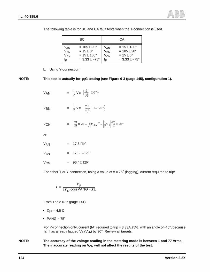
I.L. 40-385.6
124 Version 2.2X
The following table is for BC and CA fault tests when the T-connection is used.
b. Using Y-connection
NOTE: This test is actually for φφG testing (see Figure 6-3 (page 145), configuration 1).
VAN = VF
VBN = VF
VCN =
or
VAN = 17.3
VBN = 17.3
VCN = 96.4
For either T or Y connection, using a value of x = 75° (lagging), current required to trip:
From Table 6-1: (page 141)
• Z1P = 4.5 Ω
• PANG = 75°
For Y-connection only, current (IA) required to trip = 3.33A ±5%, with an angle of -45°, becauseIan has already lagged VF (Vab) by 30°. Review all targets.
NOTE: The accuracy of the voltage reading in the metering mode is between 1 and 77 Vrms.The inaccurate reading on V CN will not affect the results of the test.
BC CA
VAN = 105 ∠90°VBN = 15 ∠0°VCN = 15 ∠180°IF = 3.33 ∠−75°
VAN = 15 ∠180°VBN = 105 ∠90°VCN = 15 ∠0°IF = 3.33 ∠−75°
12---
2
3------- 0°∠
12---
2
3------- 120°–∠
32--- 70 VAN
2 12---VF
2––×
120°∠
0°∠
120°–∠
120°∠
IVF
2Z1P PANG X–( )cos--------------------------------------------------------=

I.L. 40-385.6
Version 2.2X 125
The reclose contacts (RI2-1 and RI2-2) should be closed for setting of TTYP = 2PR or 3PR,and should be open for TTYP = OFF or 1PR.
Step 14. Repeat Step 13 for both BC and CA faults. Use the following voltages for each faulttype:
6.1.1.6 Zone 2 Tests
Step 15. Press the DISPLAY SELECT push-button until the SETTINGS mode LED is dis-played. Change the setting values to:
• Z1P = “OUT” (Zone 1 phase value)
• Z1G = “OUT” (Zone 1 ground distance)
• Z2P = 4.5 Ω (Zone 2 phase value)
• T2P = 1.0 sec (Zone 2 phase timer)
• Z2G = 4.5 Ω (Zone 2 ground value)
• T2G = 1.5 sec (Zone 2 ground timer)
• Z2RI = “YES” (Zone 2 reclosing)
• TTYP = “3PR” (Reclosing mode)
Step 16. Perform Steps 10 thru 14 (above) for Zone 2 only, using delayed trip times accord-ing to the zone 2 phase timer (T2P), and the Zone 2 ground timer (T2G). Toleranc-es for T2P and T2G are 5% for an input current that is 10% above the calculatedvalue.
Repeat Step 10. The RI2 contacts 1 and 2 should be closed, and the RB contacts 1and 2 should be open. Reset Z2RI to “NO”.
Repeat Step 10 again. The RI2 contacts 1 and 2 should be open and the RB contacts 1 and2 should be closed.
Change the settings of T2G and T2P to BLK. Zone 2 should not be tripped for any type of fault.
6.1.1.7 Zone 3 Tests
Step 17. Press the DISPLAY SELECT push-button until the SETTINGS mode LED is dis-played. Change the setting values to:
• Z2P = “OUT” (Zone 2 phase value)
• Z2G = “OUT” (Zone 2 ground distance)
BC CA
VAN = 96.4 ∠120°VBN = 17.3 ∠0°VCN = 17.3 ∠−120°IF = 3.33 ∠−45°
VAN = 17.3 ∠−120°VBN = 96.4 ∠120°VCN = 17.3 ∠0°IF = 3.33 ∠−45°
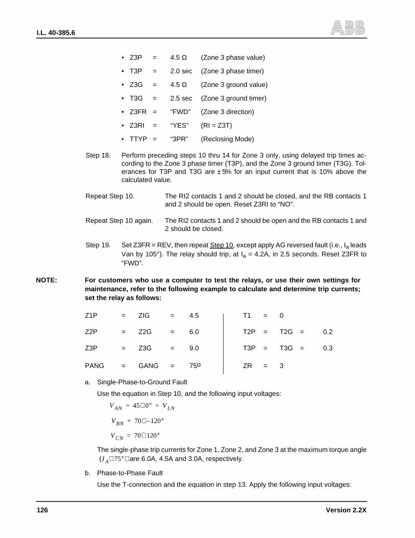
I.L. 40-385.6
126 Version 2.2X
• Z3P = 4.5 Ω (Zone 3 phase value)
• T3P = 2.0 sec (Zone 3 phase timer)
• Z3G = 4.5 Ω (Zone 3 ground value)
• T3G = 2.5 sec (Zone 3 ground timer)
• Z3FR = “FWD” (Zone 3 direction)
• Z3RI = “YES” (RI = Z3T)
• TTYP = “3PR” (Reclosing Mode)
Step 18. Perform preceding steps 10 thru 14 for Zone 3 only, using delayed trip times ac-cording to the Zone 3 phase timer (T3P), and the Zone 3 ground timer (T3G). Tol-erances for T3P and T3G are ± 5% for an input current that is 10% above thecalculated value.
Repeat Step 10. The RI2 contacts 1 and 2 should be closed, and the RB contacts 1and 2 should be open. Reset Z3RI to “NO”.
Repeat Step 10 again. The RI2 contacts 1 and 2 should be open and the RB contacts 1 and2 should be closed.
Step 19. Set Z3FR = REV, then repeat Step 10, except apply AG reversed fault (i.e., Ia leadsVan by 105°). The relay should trip, at Ia = 4.2A, in 2.5 seconds. Reset Z3FR to“FWD”.
NOTE: For customers who use a computer to test the relays, or use their own settings formaintenance, refer to the following example to calculate and determine trip currents;set the relay as follows:
Z1P = ZIG = 4.5 T1 = 0
Z2P = Z2G = 6.0 T2P = T2G = 0.2
Z3P = Z3G = 9.0 T3P = T3G = 0.3
PANG = GANG = 75ο ZR = 3
a. Single-Phase-to-Ground Fault
Use the equation in Step 10, and the following input voltages:
The single-phase trip currents for Zone 1, Zone 2, and Zone 3 at the maximum torque angleare 6.0A, 4.5A and 3.0A, respectively.
b. Phase-to-Phase Fault
Use the T-connection and the equation in step 13. Apply the following input voltages:
VAN 45 0°∠ VLN= =
VBN 70 120°–∠=
VCN 70 120°∠=
I A 75°∠( )

I.L. 40-385.6
Version 2.2X 127
The single-phase trip currents for Zone 1, Zone 2 and Zone 3 at the maximum torque angle are 4A, 3A and 2A, respectively.
c. Three-Phase Fault
Use the equation in Step 12 with the following input voltages:
The three-phase trip currents for Zone 1, Zone 2 and Zone 3 at the maximum torque angles
should be 6.0A, 4.5A and 3.0A, respectively.
6.1.1.8 Instantaneous Overcurrent (High-Set Trip)
Step 20. Using the SETTINGS mode, change the following settings:
ITP = 10A Z1P = Z1G = OUTITG = 5A Z2P = Z2G = OUTLOPB = NO Z3P = Z3G = OUT
NOTE: The High-Set ground overcurrent (ITG) and phase overcurrent (ITP) are supervised byForward Directional Ground unit (FDOG) and Forward Directional Phase unit (FDOP),respectively. In order to test the High-Set trip, the 3 φ voltages are necessary as direc-tional reference. The ITG and ITP will automatically become non-directional over- cur-rent units if the setting of LOPB is DIST, DIRU is ZSEQ or NSEQ and the LOP conditionexists.
For the setting of DIRU = DUAL and lp > 1 amp., the ITG’s directionality will be main-tained and the FDOG is determined by Ip and 3I0 even if the LOP condition exists.
Step 21. Using Figure 6-1 (page 143), configuration #1, to connect currents and voltages,apply AG fault as shown in Step 1.1.3. The REL300 should trip at Ia = 5 Amps± 5 %with a target of ITG-AG. For reversed fault, apply 10A reversed fault current (i.e.,Ia leads Van by 135° for Y-connection, or 105° for T-connection). The relay shouldnot trip.
Step 22. Using Figure 6-3 (page 145), to connect currents and voltages, apply AB fault asshown in Step 1.1.5. The REL300 should trip at Iab = 10 Amps ±5%, with a target
VAN 18 0°∠ 12---VF= =
VBN 18 180°–∠ 12---VF= =
VCN 105 90∠=
I AB 75°–∠( )
VAN 27 0°∠ VL= =
VBN 27 120°–∠=
VCN 27 120°∠=
I A 75°, I B 195°, I C +45°∠–∠–∠( )
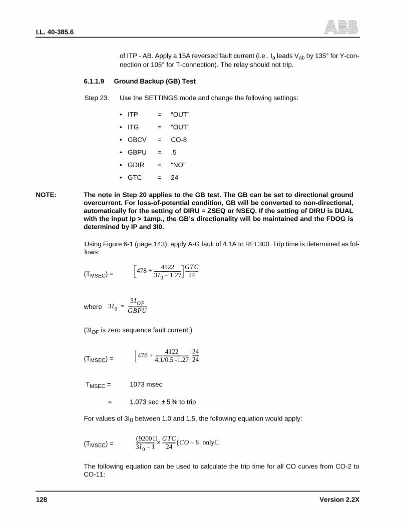
I.L. 40-385.6
128 Version 2.2X
of ITP - AB. Apply a 15A reversed fault current (i.e., Ia leads Vab by 135° for Y-con-nection or 105° for T-connection). The relay should not trip.
6.1.1.9 Ground Backup (GB) Test
Step 23. Use the SETTINGS mode and change the following settings:
• ITP = “OUT”
• ITG = “OUT”
• GBCV = CO-8
• GBPU = .5
• GDIR = “NO”
• GTC = 24
NOTE: The note in Step 20 applies to the GB test. The GB can be set to directional groundovercurrent. For loss-of-potential condition, GB will be converted to non-directional,automatically for the setting of DIRU = ZSEQ or NSEQ. If the setting of DIRU is DUALwith the input Ip > 1amp., the GB’s directionality will be maintained and the FDOG isdetermined by IP and 3I0.
Using Figure 6-1 (page 143), apply A-G fault of 4.1A to REL300. Trip time is determined as fol-lows:
(TMSEC) =
where
(3IOF is zero sequence fault current.)
(TMSEC) =
TMSEC = 1073 msec
= 1.073 sec ± 5 % to trip
For values of 3I0 between 1.0 and 1.5, the following equation would apply:
(TMSEC) =
The following equation can be used to calculate the trip time for all CO curves from CO-2 toCO-11:
478 41223I 0 1.27–------------------------+
GTC24
------------
3I 0
3I OF
GBPU-----------------=
478 41224.1/0.5 -1.27------------------------------+
2424------
9200( )3I 0 1–-----------------
GTC24
------------× CO 8 only–( )

I.L. 40-385.6
Version 2.2X 129
T(sec) =
T(sec) =
where
GBPU = Pickup current setting (0.5 to 4.0A).
GTC = Time curve dial setting (1 to 63).
To, K, C, P and R are constants, and are shown in Table 6-2 (page 141).
Step 24. For a Zero Sequence Directional unit (DIRU = ZSEQ), the tripping direction ofREL300 is: the angle of 3I0 leads 3V0 between +30° and +210°. Change the settingof GDIR to “YES”. Apply AG fault as shown in preceding Step 10, Figure 6-1(page 143). The relay should trip at the following angles:
• +28°• -60° (± 88°)• -148°
The relay should not trip at the angles of:
• +32°• +120° (± 88°)• -152°
For a Negative Sequence Directional Unit (DIRU = NSEQ), the tripping direction of REL300 is:I2 leads V2 by a value between +8° and +188°. The relay should trip at the following angles:
• +3°• -82° (± 85°)• -167°
The relay should not trip at the angles of:
• +13°• +98° (± 85°)• +183°
Step 25. For a dual polarizing ground directional unit (DIRU = DUAL) test, connect the testcircuit shown in Figure 6-4; (page 146) apply Ip = 1.5 A to terminals 12 (+)and 11(-), and apply a balanced 3-phase voltage (70V) to Va, Vb, Vc, and Vn. ApplyIa = 4A to terminals 6(+) and 5(-).
T0K
3I 0 C–( )p--------------------------+
GTC24 000,------------------ for 3I 0 1.5≥( )×
R3I 0 1–( )----------------------
GTC24 000,------------------× for 1 3I 0 1.5< <( )
3I 0
3I OF
GBPU-----------------=
90°–∠

I.L. 40-385.6
130 Version 2.2X
NOTE: Ip has to be greater than 1.0 ampere for the current polarization; otherwise it will beconverted to zero sequence voltage polarization automatically.
NOTE: In order to eliminate the voltage polarizing effect, make sure the voltages are finely bal-anced so that 3V 0 is less than 1.0 volt.
The relay should trip at the following angles:
• -3°• -90o ( ±87°)• -177°
The relay should not trip at the following angles:
• +3°• +90° ( ±87°)• +177°
6.1.1.10 CIF, STUB, IOM, IL and LV Tests
Step 26. Set the relay per Table 6-1 (page 141). Change the following settings: IOM = 3, IL= 2, CIF = CF, and connect a rated dc voltage to 52b, between TB5/3 (+) and TB5/4 (-). Apply an AG fault as shown in Step 10 (Figure 6-1, page 143). The relayshould trip at Ia = 2A (IL) with CIF target. Change IL setting from 2 to 3.5A and re-peat the test shown in Step 26. The relay should trip at Ia = 3A (IOM) with CIF tar-get. Change the setting CIF = CFT and Ia = 3.2A. Repeat the test. The relay shouldtrip with a display of CIF and a time delay of 200 ms. (Refer to Section 3.4.7(page 32) for the application of CFT setting.) Reset CIF = CF.
Step 27. LV setting test. Set LV = 60 and with IAN = 4A, apply AG fault as shown in Step 10.The CIF trip should be for VAN <60 Vrms ± 5%.
Step 28. For STUB Bus Protection (SBP), check the blue jumpers on the Interconnect mod-ule. JMP7 and 9 should be IN; JMP13 should be at the rated voltage position. Se-lect CIF = STUB. Disconnect the voltage from 52b and connect it to terminals TB5/13(+) and TB5/14(-).
NOTE: Make sure the jumpers (JMP8 and JMP10) are not IN before applying the voltage toTB5/13(+) and TB5/14(-).
Apply IA = 4A. The STUB bus trips for any VAN voltage with a target of CIF. Disconnect thevoltage from SBP and reset IOM = IL = 0.5 and CIF = NO.
6.1.1.11 Load-Loss-Trip (LLT) and Loss-of-Potential (LOP) Tests
Step 29. For Load Loss Trip (LLT), set:
LLT = YesZ2P = Z2G = 4.5 ohmsT2P = T2G = 2.99 sec (or BLK)ZIP = ZIG = OUT

I.L. 40-385.6
Version 2.2X 131
Apply:
Va = 30
Vb = 70
Vc = 70
Ia = 3.5
Ib = 1
Ic = 1
Suddenly increase Ia from 3.5 to 4.5A and then turn Ib OFF immediately. The relayshould trip with LLT target. The trip is accelerated due to the pickup of Zone 2 andthe setting of LLT = YES.
Change the setting of LLT = FDOG and the input current Ia from 1.5 to 2.5A; thenturn Ib OFF immediately. The relay should trip with a target of LLT. The trip is dueto the pickup of FDOG and setting of LLT = FDOG.
Reset: LLT = NO
Z2P = Z2G = OUT
T2P = T2G = BLK
Step 30. Disconnect all current inputs. Connect 3 balanced voltages of 70 Vac to Van, Vbn,and Vcn. Using the SETTINGS mode, change the setting: LOPB = DIST.
NOTE: The “RELAY IN SERVICE” LED will not be turned “OFF” for the condition of settingLOPB = DIST, but Zone 1, 2, 3 and pilot distance units will be blocked and all overcur-rent units (GB, ITP, and ITG) will be converted to non-directional operation.
LOPB will be set if the following logic is satisfied:
• one (or more) input voltages (VAN, VBN or VCN) are detected (as <7 Vrms) with-out ∆I change, or
• a 3Vo (> 7Vrms) is detected with 3Io <Ios
• Apply VAN, VBN and VCN rated voltage to REL300. Scroll the LED to meteringmode; the display shows LOPB = NO. Reduce VAN to 62 Vrms (e.g., 3V0 = 8V).After approximately 0.5 seconds, the display shows LOPB = YES and the form Cfailure alarm (AL1) contact is also deenergized.
Step 31. Set the relay as follows:
Z1P = 4.5 GBCV = CO-8
Z1G = 4.5 GBPU = 0.5
0°∠
120°–∠
120°∠
75°–∠
120°–∠
+120°∠

I.L. 40-385.6
132 Version 2.2X
ITP = 10 GDIR = YES
ITG = 5 GTC = 24
Repeat Step 10. AG Fault) with IAN = 4.5A. While in the metering mode, be surethat LOPB = YES before the fault current is applied. The relay should be trippedwith a target of GB. Apply 5.5A; the relay should be tripped with a target of ITG.Repeat the test with a reversed AG Fault; the relay will trip. Reset LOPB = NO; therelay should not trip for the reversed fault. Set LOPB = ALL. The relay “In Service”LED will be turned off for the fault voltages applied and the relay will not trip for theforward or reverse fault current (4.5A).
Step 32. Set LOPB = DIST. Apply a balanced three-phase voltage (70 Vrms) and current(3A). Turn off Va; the relay should not trip. Reset LOPB to NO.
6.1.1.12 Loss-Of-Current (LOI) Test
Step 33. Set LOIB to YES and IOM = 1.0A. Apply a balanced three-phase voltage (70Vrms). Connect the current inputs per Figure 6-1 (page 143), and apply a singlephase current of 1.1A to IA. After approximately 10 seconds, the “Relay In Service”LED will be turned off, and the Form C failure alarm (AL1) contact will be droppedout (deenergized) indicating a failure condition.
Step 34. Increase IA to 1.5A. Depress the DISPLAY SELECT push-button and change tothe metering (VOLTS/AMPS/ANGLE) mode. Press FUNCTION RAISE push-but-ton until the LOI display is shown. The value should indicate “YES”. Suddenly turnOFF VA voltage; the relay should not be tripped within 500 ms. It may operate after500 ms if a delta I is detected by the relay. Change the setting of LOIB from YESto NO.
6.1.1.13 Output Contact Test
Step 35. The purpose of this test is to check the hardware connections and relay contacts.It is designed for a bench test only. Remove JMP12 (spare on the MicroprocessorPC Board) and place it in the JMP5 position. Open the red-handled FT switch (Tripand Breaker Failure Initiate) in order to avoid the undesired trip.
NOTE: The red-handled FT switch (#13) controls the dc supply of BFI, RI2 and the optional RI1relays. In order to test these relays in the system, the external wiring should be dis-connected to avoid undesired reclosing or trip. For relays without FT switches, do notperform the Output Contact tests using the relay system.
Change the LED mode to “TEST” and select the tripping function field and the de-sired contact in the value field. Push the ENTER button; the ENTER LED shouldbe “ON”. The corresponding relay should operate when the ENTER button ispressed. The following contacts can be tested:
• TRIP
• BFI
• RI1 (optional)
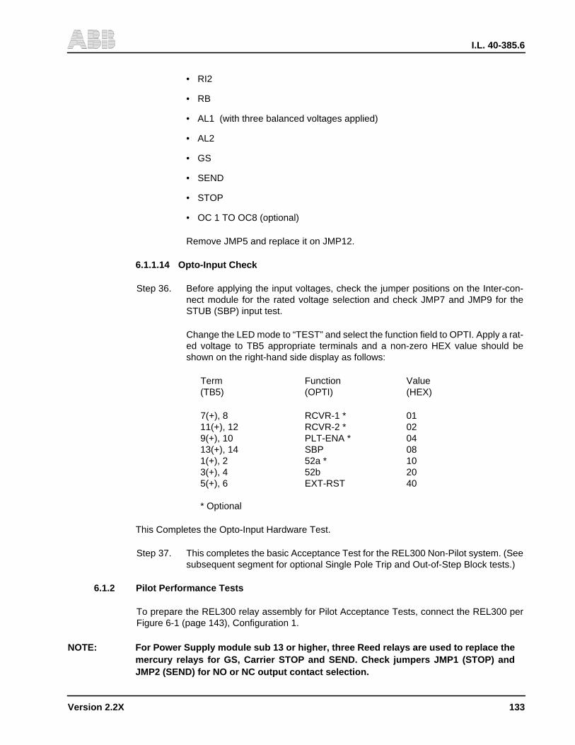
I.L. 40-385.6
Version 2.2X 133
• RI2
• RB
• AL1 (with three balanced voltages applied)
• AL2
• GS
• SEND
• STOP
• OC 1 TO OC8 (optional)
Remove JMP5 and replace it on JMP12.
6.1.1.14 Opto-Input Check
Step 36. Before applying the input voltages, check the jumper positions on the Inter-con-nect module for the rated voltage selection and check JMP7 and JMP9 for theSTUB (SBP) input test.
Change the LED mode to “TEST” and select the function field to OPTI. Apply a rat-ed voltage to TB5 appropriate terminals and a non-zero HEX value should beshown on the right-hand side display as follows:
Term Function Value(TB5) (OPTI) (HEX)
7(+), 8 RCVR-1 * 0111(+), 12 RCVR-2 * 029(+), 10 PLT-ENA * 0413(+), 14 SBP 081(+), 2 52a * 103(+), 4 52b 205(+), 6 EXT-RST 40
* Optional
This Completes the Opto-Input Hardware Test.
Step 37. This completes the basic Acceptance Test for the REL300 Non-Pilot system. (Seesubsequent segment for optional Single Pole Trip and Out-of-Step Block tests.)
6.1.2 Pilot Performance Tests
To prepare the REL300 relay assembly for Pilot Acceptance Tests, connect the REL300 perFigure 6-1 (page 143), Configuration 1.
NOTE: For Power Supply module sub 13 or higher, three Reed relays are used to replace themercury relays for GS, Carrier STOP and SEND. Check jumpers JMP1 (STOP) andJMP2 (SEND) for NO or NC output contact selection.
I.L. 40-385.6
134 Version 2.2X
6.1.2.1 Front Panel Check
Step 1. Repeat steps 1 thru 6 in Non-Pilot Acceptance Tests.
Step 2. Change the value settings, in Table 6-1 (page 141), as follows:
• PLT YES • PLTP 6.0 • PTRI YES
• Z3FR REV • Z3P 6.0
• ZIP OUT • Z3G 6.0
• ZIG OUT • T3P BLK
• PLTG 6.0 • T3G BLK
NOTE: When the dc voltage is applied to TB5 terminals, check jumper position on Intercon-nect module for the appropriate selection.
Connect a rated dc voltage to PLT/ENA terminals TB5/9(+) and TB5/10(-).
6.1.2.2 Blocking (BLK) Scheme
Step 3. Change the STYP setting to BLK. Apply a rated dc voltage to RCVR #1 terminalsTB5/7(+) and TB5/8(-). Check the metering mode for RX1 = YES. Apply an AG faultas shown in Step 10 of the Non-Pilot Acceptance Test (i.e., Va = 30 volts and Ia =4 Amps). The trip A contacts should not be closed. The CARRY SEND should be“open” and the CARRY STOP should be “closed”.
Step 4. Remove the dc voltage from RCVR #1 and apply AG fault. Trip A and RI2 (TB3/5& 6 and TB3/7 & 8) contacts should be “closed” and the target should show “PLTGAG”. Set PTRI = NO. Repeat the test and the RI2 should not be closed.
Change the LED mode to “TEST” and select the “RS1” function. Push the ENTER button; theENTER LED should be “ON”. Repeat Step 4 with the ENTER button depressed.The relay should not trip.
Step 5. Apply AG reversed fault (i.e., Ia leads Va by 105 degrees). The CARRY SEND con-tacts should be “closed” and the CARRY STOP contacts should be “open”. (Iashould be > 3A for the Zone 3 setting of 6 ohms.)
Step 6. Change the LED mode to TEST and select the function “TK”. Push the ENTER but-ton; the ENTER LED should be “ON” and the CARRY SEND contacts should beclosed.
Step 7. In order to determine setting accuracy (6 ohms), the forward directional ground unitmust be disabled. Set FDGT = BLK. Repeat preceding Step 4 of the Pilot Accep-tance Test, with a trip input current (Ia) of 3 Amps (± 5%).
Step 8. Set the Forward Directional Ground Timer (FDGT) from 0 to 15 cycles. RepeatStep 4 with Ia = 1.5 A. The relay should be tripped after the delay time of FDGT.
NOTE: The FDOG trip is determined by the IOM setting. It trips if 3I 0 >IOM and the forwardground directional unit picks up.

I.L. 40-385.6
Version 2.2X 135
Step 9. In order to perform the Breaker Failure Reclose Block Test, change the setting ofFDGT = 0 and BFRB = NO. Repeat test Step 4; RB contacts (TB3/1 and TB3/2)should not close. Change BFRB to YES and repeat the test. The RB contactsshould be closed with a time delay between 150 ms and 200 ms.
NOTE: For Va = Vb = Vc = 0, Ia = Ib = Ic = 0, the setting of OSB = YES, WFEN = NO, and theinput of 52b = OV, the carrier SEND contacts will be closed. This is not desirable, butoccurs only on the test bench. If tested with the relay system, V = 0 and I = 0 mean thatthe 52b input is at a rated voltage which will stop the SEND signal.
6.1.2.3 PUTT or POTT Schemes
Step 10. Change the setting to STYP = PUTT (for underreach scheme) or STYP = POTT(for overreach scheme). In order to determine setting accuracy (6 ohms), the for-ward directional ground unit must be disabled. Set FDGT = BLK. Apply a rated volt-age to RCVR #1 terminals TB5/7(+) and TB5/8(-), and apply an AG fault as shownin Step 10 of the Non-Pilot Acceptance Test. The trip contact A should be closedat the input Ia = 3A (± 5%); the target should show “PLTG AG”, and the CARRYSEND contact should be “closed” for POTT setting. The RI2 should be “closed” ifPTRI is set to “YES”. Do not test carry STOP for POTT and PUTT schemes.
Step 11. Apply a reversed AG fault (Ia leads Va by 105°). The relay should not trip, and theCARRY SEND contact should stay “open”.
Step 12. Remove the voltage on RCVR #1. Apply a forward AG fault as shown in Step 10.The trip contacts should remain “open” for Ia = 5A.
Step 13. Change the LED mode to TEST and select the function “RS1”. Push the ENTERbutton; the ENTER LED should be “ON”. Repeat Step 12 with the ENTER buttondepressed. The relay should trip.
Step 14. Repeat steps 8 and 9 for FDGT and BFRB tests, by using Step 10 with Ia = 1.5 A.
6.1.2.4 Weakfeed Scheme
Step 15. This function is for POTT only. In addition to the setting changes in Step 2, changethe following settings:
• STYP POTT
• WFEN YES
• Z3G 4.5
• Z3P 4.5
• Z3FR REV
Apply a rated voltage to PLT/ENA terminals TB5/9(+) and TB5/10(-), also RCVR#1 terminals TB5/7(+) and TB5/8(-).
With Van = Vbn = Vcn = 70 Vrms applied (as shown in Figure 6-1, page 143), therelay should operate normally.
I.L. 40-385.6
136 Version 2.2X
NOTE: Do not apply fault current.
Turn Van “OFF”; the relay should trip with a target of WFT, and the Carrier Sendcontact (TB4-1 and TB4-2) should close momentarily.
Apply a balanced 3-phase 70 Vrms and apply a reverse AG fault current of 5A (i.e.,Ia leads Van by 105 degrees). Turn Van “OFF”; the relay should not trip, and theCarrier Send contact (TB4-1 and TB4-2) should stay open.
Step 16. This completes the basic Acceptance Test for the REL300 Pilot System. (See sub-sequent segments for optional Single Pole Trip test.)
6.1.3 Single Pole Trip (Option) Acceptance Tests
Step 1. Set relay per Table 6-1 (page 141). Check the 62T setting; it should be 5.000. Fora Pilot System, change the setting to PLT = YES, and apply a rated dc voltage toPilot Enable terminals TB5/9(+) and TB5/10(-). Also apply a rated voltage to RCVR#1 terminals TB5/7(+) and TB5/8(-) if the STYP = POTT or PUTT; set TTYP = SPR.
Apply AG fault as shown in this Section 6.1.1.3, Step 10. The Trip A contacts (2FT-14/1-2 and 3-4) should be closed. Repeat BG fault (for Trip B contact closures) andrepeat CG-Fault (for Trip C contact closures).
6.1.3.1 Sound Phase Fault (SPF) and 62T Trip
Step 2. Apply a rated dc voltage to 52a terminals TB5/1(+) and TB5/2(-) and to 52b termi-nals TB5/3(+) and TB5/4(-). Connect a Westinghouse Lockout (WL) switch to thetrip circuit.
Step 3. Apply a phase-to-phase fault (as shown in this section 6.1.1.5, Step 13). Turn thefault current “ON” and “OFF”. The WL switch trips with a target of SPF.
Step 4. Set the WL switch, immediately; it will trip again with a target of 62T. Remove thevoltages from 52a and 52b.
6.1.3.2 Reclose (RI) Trip and Breaker Failure (BFI) Contacts
Step 5. Refer to the Non-Pilot Acceptance Test for the single-phase-to-ground faults(Steps 10 and 11), and to the three-phase fault (Step 12). The fault current shouldbe 20% greater than the calculated values for the tests in these steps. The “faulttypes” applied to the REL300 relay are shown in Table 6-2 (column 2, page 141).TTYP settings are shown in column 1, whereas the results of RI, Trip, and BFI con-tacts are shown in columns 3, 4, and 5, respectively.
6.1.4 REL300 With Out-of-step Block Option
Refer to Figure 6-5 (page 147). The RT setting (21BI) is for the inner blinder and it is also usedfor three-phase fault load restriction. The RU setting (21BO) is for the outer blinder. If the settingof OSB is “YES”, and the power swing stays inside the two parallel lines (RT and RU) for morethan 50 ms, the three-phase fault trip will be blocked until the timer (OSOT) times out.
Connect the test circuit as shown in Figure 6-2 (page 144).

I.L. 40-385.6
Version 2.2X 137
6.1.4.1 Condition OSB = NO
Step 1. Set the relay per Table 6-1 (page 141), except for the following settings:
• Z1P = 10
• Z1G = 10 • T2P = 0.1
• Z2P = 20 • T2G = 0.1
• Z2G = 20
(Check: PANG = GANG = 75; RT = RU = 15; OSOT = 4000)
Step 2. Adjust the inputs as follows:
Step 3. Apply current IF of 2.35A ±5% suddenly. The relay should trip with a display of Z2P
= ABC.
Step 4. Apply IF of 4.7A ± 5% suddenly. The relay should trip with a display of Z1P =
ABC.
Step 5. Change the RT setting from 15 to 4. Repeat Steps 3 and 4 (above). The relayshould not trip because the RT restricts the 3-phase fault current.
NOTE: The trip current ( IF) can be obtained from the equation in test Step 12 (6.1.1.4, page 124Zone 1 Test/Three-Phase), with the parameters:
VLN = 40 PANG = 75
Z1P = 10 (or Z2P = 20) X = 45
6.1.4.2 Condition OSB = YES
Change the OSB setting from NO to YES and RT = 4, RU = 8.
Step 1. Change the LED to metering mode with the display of OSB = NO.
Step 2. Apply a current IF of 2.7A ± 5% suddenly. The display should show OSB = YES for4 seconds. This means the input power swing is inside the outer blinder (2IBO).Repeat this test for IF = 4A and 4.5A. The display should show OSB = YES be-
cause the power swing is within two blinders (2IBO and 2IBI).
Va 40 0°∠= I a I F 45°–∠=
Vb 40 120°–∠= I b I F 165°–∠=
Vc 40 120°∠= I c I F 75°∠=

I.L. 40-385.6
Version 2.2X 138
Step 3. Apply a current of 4.5A and increase the IF to 5.5A immediately. The relay shouldtrip with a display of Z2P = ABC (or Z1P = ABC). This means the power swing staysinside the blinders for more than 50 ms and then crosses over 21BI. For the currentof 4.5A, Z1P or Z2P may pick up, but the relay trips after the OSOT timer times out.
Step 4. Apply IF of 5.25A suddenly (5% above the calculated value). The relay should tripwith a display Z1P = ABC. The trip time should be <2 cycles.
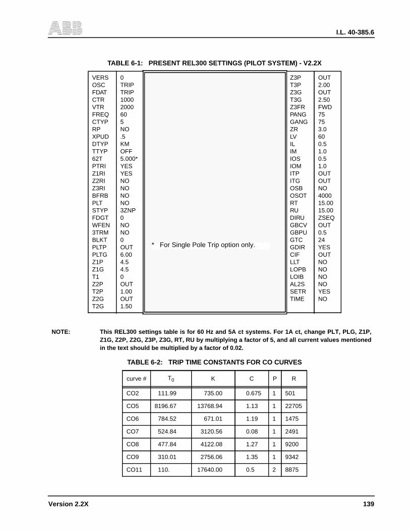
I.L. 40-385.6
Version 2.2X 139
NOTE: This REL300 settings table is for 60 Hz and 5A ct systems. For 1A ct, change PLT, PLG, Z1P,Z1G, Z2P, Z2G, Z3P, Z3G, RT, RU by multiplying a factor of 5, and all current values mentionedin the text should be multiplied by a factor of 0.02.
TABLE 6-1: PRESENT REL300 SETTINGS (PILOT SYSTEM) - V2.2X
VERSOSCFDATCTRVTRFREQCTYPRPXPUDDTYPTTYP62TPTRIZ1RIZ2RIZ3RIBFRBPLTSTYPFDGTWFEN3TRMBLKTPLTPPLTGZ1PZ1GT1Z2PT2PZ2GT2G
0TRIPTRIP10002000605NO.5KMOFF5.000*YESYESNONONONO3ZNP0NONO0OUT6.004.54.50OUT1.00OUT1.50
Z3PT3PZ3GT3GZ3FRPANGGANGZRLVILIMIOSIOMITPITGOSBOSOTRTRUDIRUGBCVGBPUGTCGDIRCIFLLTLOPBLOIBAL2SSETRTIME
OUT2.00OUT2.50FWD75753.0600.51.00.51.0OUTOUTNO400015.0015.00ZSEQOUT0.524YESOUTNONONONOYESNO
TABLE 6-2: TRIP TIME CONSTANTS FOR CO CURVES
curve # T0 K C P R
CO2 111.99 735.00 0.675 1 501
CO5 8196.67 13768.94 1.13 1 22705
CO6 784.52 671.01 1.19 1 1475
CO7 524.84 3120.56 0.08 1 2491
CO8 477.84 4122.08 1.27 1 9200
CO9 310.01 2756.06 1.35 1 9342
CO11 110. 17640.00 0.5 2 8875
* For Single Pole Trip option only.

I.L. 40-385.6
140 Version 2.2X
TABLE 6-3: FAULT TYPES APPLIED TO REL300
SettingTTYP
Fault TypeApplied
Out ContactsRI TRIP BFI
OFF AGBGCG
ABC
NO A,B,C A,B,CNO A,B,C A,B,CNO A,B,C A,B,CNO A,B,C A,B,C
1PR AGAB
ABC
RI2 A,B,C A,B,CNO A,B,C A,B,CNO A,B,C A,B,C
2PR AGAB
ABC
RI2 A,B,C A,B,CRI2 A,B,C A,B,CNO A,B,C A,B,C
3PR AGBGCGAB
ABC
RI2 A,B,C A,B,CRI2 A,B,C A,B,CRI2 A,B,C A,B,CRI2 A,B,C A,B,CRI2 A,B,C A,B,C
SPR AGBGCG
ABC
RI1 A ARI1 B BRI1 C CNO A,B,C A,B,C
SR3R AGBGCG
ABC
RI1 A ARI1 B BRI1 C CRI2 A,B,C A,B,C
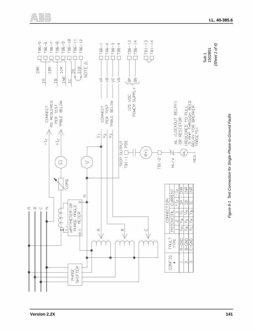
I.L. 40-385.6
Version 2.2X 141
1502
B51
Sub
1
(She
et 1
of 4
)
Fig
ure
6-1
Test
Con
nect
ion
for
Sin
gle-
Pha
se-t
o-G
roun
d Fa
ults

I.L. 40-385.6
142 Version 2.2X
1502
B51
Sub
1
(She
et 2
of 4
)
Fig
ure
6-2
Test
Con
nect
ion
for
Thr
ee-P
hase
Fau
lts
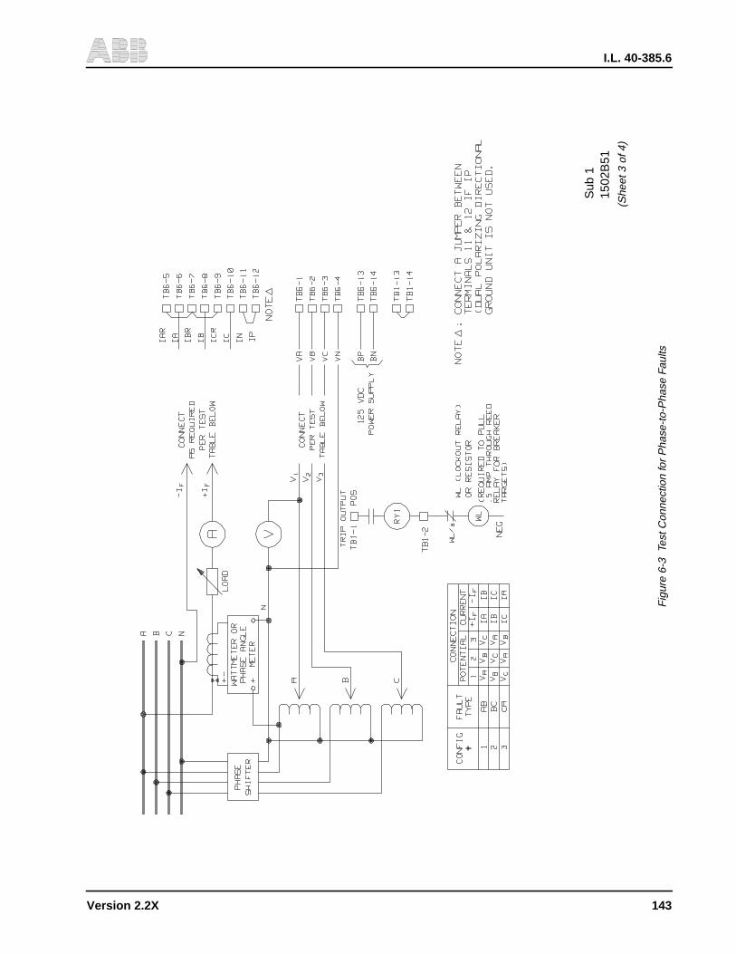
I.L. 40-385.6
Version 2.2X 143
1502
B51
Sub
1
(She
et 3
of 4
)
Fig
ure
6-3
Test
Con
nect
ion
for
Pha
se-t
o-P
hase
Fau
lts
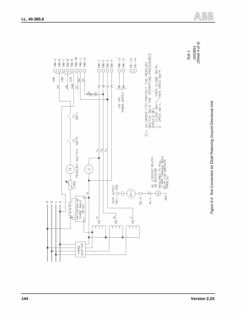
I.L. 40-385.6
144 Version 2.2X
1502
B51
Sub
1
(She
et 4
of 4
)
Fig
ure
6-4
Test
Con
nect
ion
forD
ual P
olar
izin
g G
roun
d D
irect
iona
l Uni
t

I.L. 40-385.6
Version 2.2X 145
9651A71Sub 1
22
21
20
19
18
17
16
15
14
13
12
11
10
9
8
7
6
5
4
3
2
1
-8 -7 -6 -5 -4 -3 -2 -1 1 2 3 4 5 6 7 8 9 10 11 12 13 14
R
Z2 = 20 ∠−75˚
Z1 = 10 ∠−75˚
jX
RT RU
Z = 17.3 ∠ -45˚(I = 2.35 Amps)
ZU = 16 ∠-45˚(I = 2.5 Amps)
Z = 8.7∠-45˚(I = 4.7 Amps)
ZT = 8.7∠-45˚(I = 5.0 Amps)
4 OHMS
8 OHMS
INPUTS: Va = 40 ∠0˚, Vb = 40 ∠-120˚, Vc = 40 ∠120˚SETTINGS: PANG = 75˚, GANG = 75˚, ZR = 3ABC FAULT WITH FAULT ANGLE OF 45˚
75˚ 45˚
Figure 6-5 REL300 with Out-of-Step Block Optior
I.L. 40-385.6
146 Version 2.2X
THIS PAGE RESERVED FOR NOTES
I.L. 40-385.6
Version 2.2X 147
Section 7. ACCEPTANCE/MAINTENANCE TESTS
Maintenance qualification tests will determine if a particular REL300 unit is working correctly.Refer to the WARNING note in Section 6.1 (page 119) before energizing the relay.
7.1 NON-PILOT MAINTENANCE TESTS
It is recommended that either Doble or Multi-Amp test equipment should be used for this test.Refer to Figure 6-1, (page 141) for the input voltage and current terminal connection per con-figuration 1. Check all jumper positions on the Interconnect module for rated dc voltage.
7.1.1 Front Panel and Metering Check
Step 1. Turn on rated dc voltage. Check the FREQ setting; it should match the line frequen-cy and ct type (CTYP). Apply a balanced 3-phase voltage (70 Vac); the Alarm 1relay should be energized. (Terminal TB4/7 and TB4/8 should be zero ohms.) The“Relay-in-Service” LED should be “ON”.
Step 2. Press RESET push-button; the green LED (Volts/Amps/Angle) should be “ON”.Press the FUNCTION RAISE or FUNCTION LOWER push-button. Read the inputvoltages and their angles:
VAG = 70 ∠0°VBG = 70 ∠−120°VCG = 70 ∠120°
with an error of ± 1 volt and ± 2°.
Step 3. Press the DISPLAY SELECT push-button, and note that the mode LED cycles thruthe five display modes. Release the push-button so that the SETTINGS mode LEDis “ON”. Press the RAISE button to scroll thru the FUNCTION FIELD to check thesettings per Table 6-1 (page 139). Change the setting, if necessary, by depressingthe RAISE button in the VALUE FIELD to the desired value and then pressing theENTER button. The Value Excepted LED should be lit to confirm the new data en-try.
Step 4. Press the RESET push-button (LED jumps to Metering mode). Apply 3.0 A to IAwith an angle of -75°. Read IA from the front display; it should be 3.0 ∠−75° with anerror of 5% and ± 2°. Move the input current from IA to IB or IC terminal. Read IBor IC to verify the transformer’s accuracy.
7.1.2 Impedance Accuracy Check
Step 5. Apply voltages to REL300 as follows:
VA = 30 ∠0°VB = 70 ∠-120°VC = 70 ∠120°
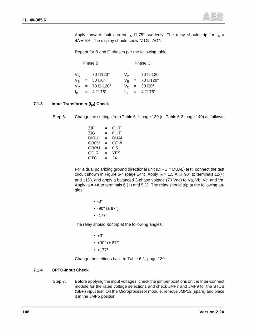
I.L. 40-385.6
148 Version 2.2X
Apply forward fault current IA ∠-75° suddenly. The relay should trip for IA =4A ± 5%. The display should show “Z1G AG”.
Repeat for B and C phases per the following table:
Phase B Phase C
VA = 70 ∠120° VA = 70 ∠-120°VB = 30 ∠0° VB = 70 ∠120°VC = 70 ∠-120° VC = 30 ∠0°IB = 4 ∠-75° IC = 4 ∠-75°
7.1.3 Input Transformer (I P) Check
Step 6. Change the settings from Table 6-1, page 139 (or Table 6-3, page 140) as follows:
ZIP = OUTZIG = OUTDIRU = DUALGBCV = CO-8GBPU = 0.5GDIR = YESGTC = 24
For a dual polarizing ground directional unit (DIRU = DUAL) test, connect the testcircuit shown in Figure 6-4 (page 144). Apply IP = 1.5 A ∠−90° to terminals 12(+)and 11(-), and apply a balanced 3-phase voltage (70 Vac) to Va, Vb, Vc, and Vn.Apply Ia = 4A to terminals 6 (+) and 5 (-). The relay should trip at the following an-gles:
• -3°
• -90° (± 87°)
• -177°
The relay should not trip at the following angles:
• +3°
• +90° (± 87°)
• +177°
Change the settings back to Table 6-1, page 139.
7.1.4 OPTO-Input Check
Step 7. Before applying the input voltages, check the jumper positions on the Inter-connectmodule for the rated voltage selections and check JMP7 and JMP9 for the STUB(SBP) input test. On the Microprocessor module, remove JMP12 (spare) and placeit in the JMP5 position.
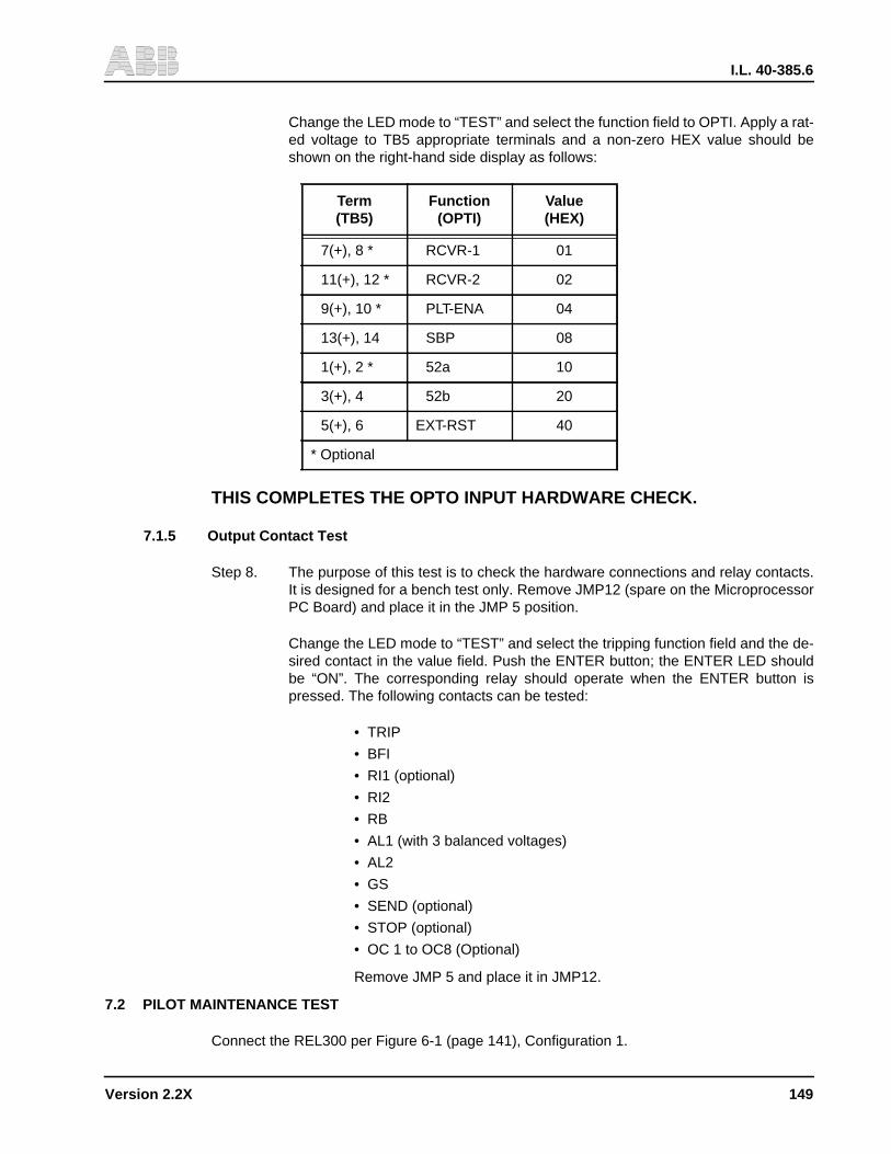
I.L. 40-385.6
Version 2.2X 149
Change the LED mode to “TEST” and select the function field to OPTI. Apply a rat-ed voltage to TB5 appropriate terminals and a non-zero HEX value should beshown on the right-hand side display as follows:
THIS COMPLETES THE OPTO INPUT HARDWARE CHECK.
7.1.5 Output Contact Test
Step 8. The purpose of this test is to check the hardware connections and relay contacts.It is designed for a bench test only. Remove JMP12 (spare on the MicroprocessorPC Board) and place it in the JMP 5 position.
Change the LED mode to “TEST” and select the tripping function field and the de-sired contact in the value field. Push the ENTER button; the ENTER LED shouldbe “ON”. The corresponding relay should operate when the ENTER button ispressed. The following contacts can be tested:
• TRIP
• BFI
• RI1 (optional)
• RI2
• RB
• AL1 (with 3 balanced voltages)
• AL2
• GS
• SEND (optional)
• STOP (optional)
• OC 1 to OC8 (Optional)
Remove JMP 5 and place it in JMP12.
7.2 PILOT MAINTENANCE TEST
Connect the REL300 per Figure 6-1 (page 141), Configuration 1.
Term(TB5)
Function(OPTI)
Value(HEX)
7(+), 8 * RCVR-1 01
11(+), 12 * RCVR-2 02
9(+), 10 * PLT-ENA 04
13(+), 14 SBP 08
1(+), 2 * 52a 10
3(+), 4 52b 20
5(+), 6 EXT-RST 40
* Optional

I.L. 40-385.6
150 Version 2.2X
7.2.1 Basic Function Test
Step 1. Repeat Step 1 thru 8 in the Non-Pilot Maintenance Test (7.1.1 thru 7.1.5).
7.2.2 Input Opto-Coupler Check
The following test steps 2 and 3 are optional since the OPTO inputs PLT-ENA, RCVR-1 andRCVR-2 have been checked in Section 7.1.4.
Step 2. PLT ENA Terminals Change the following settings from Table 6-1 (page 139):
• PLTYES
• Z1P0UT
• Z1GOUT
• PLTPOUT
• PLTG6.0
• Z3POUT
• Z3G6.0
• T3PBLK
• T3GBLK
• Z3FR1REV
a. Block Systems OnlyChange the STYP setting to BLK. Apply a forward fault, as shown in the Non-Pilot Mainte-nance Test, step 5. The relay should not trip.
Apply a rated dc voltage to PLT ENA terminals TB 5/9(+) and TB 5/10(-). Repeat the test.The relay should trip.
b. POTT/PUTT Systems OnlyChange the STYP setting to POTT. Change the LED mode to TEST and select the function“RS1”. Push the ENTER button; the LED should be “ON”. Apply a forward fault as shownin Non-Pilot Maintenance test, Step 5. With the ENTER button depressed, the relay shouldnot trip. Apply a rated dc voltage to terminals TB 5/9(+) and TB 5/10(-). Repeat the test.The relay should trip.
Step 3. Receivers 1 and 2Apply a dc voltage to PLT ENA terminals TB 5/9(+) and TB5/10(-).
a. Block Systems OnlyChange the STYP setting to BLK. Apply a forward fault as shown in the Non-Pilot Mainte-nance test, Step 5. The relay should trip.
Apply a rated dc voltage to RCVR #1 terminals TB 5/7 (+) and TB 5/8(-). Repeat the test.The relay should not trip. Move the dc voltage from RCVR #1 to RCVR #2 terminals TB 5/11(+) and TB 5/12(-), and repeat this test for RCVR #2.
I.L. 40-385.6
Version 2.2X 151
b. POTT/PUTT Systems OnlyChange the STYP setting to POTT. Apply a forward fault as shown in the Non-Pilot Main-tenance test, Step 5. The relay should not trip. Apply a rated dc voltage to RCVR #1terminals TB 5/7(+) and TB 5/8(-). Repeat the test. The relay should trip.
Move the dc voltage from RCVR #1 to RCVR #2 terminals TB 5/11(+) and TB 5/12(-), andrepeat this test for RCVR #2.
7.3 SINGLE-POLE TRIP TEST
7.3.1 Output Contact Test
Step 1. Set relay according to Table 6-1 (page 139). Check the 62T setting; it should be5.000.
For a Pilot system, change the PLT setting to YES, and apply rated dc voltage toPilot enable terminals TB 5/9(+) and TB 5/10(-). Also, apply a rated voltage toRCVR #1 terminals TB 5/7(+) and TB 5/8(-) if the STYP = POTT or PUTT; setTTYP = SPR.
Step 2. Repeat Non-Pilot Maintenance test, step 5 for trip and BFI. Check the contact clo-sures for Trip A, Trip B, Trip C and BFIA, BFIB, BFIC.
7.3.2 Input Opto-Coupler Check
The following test step 3 is optional since the OPTO input 52a has been checked in Section7.1.4.
Step 3. 52a TerminalsApply a rated voltage to 52b terminals TB 5/3(+) and TB 5/4(-) and then apply arated voltage to 52a terminals TB 5/1(+) and TB 5/2(-). The relay should trip in 5seconds with a display of 62T.

I.L. 40-385.6
152 Version 2.2X
THIS PAGE RESERVED FOR NOTES
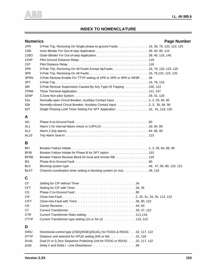
I.L. 40-385.6
Version 2.2X 153
Numerics Page Number1PR 3-Pole Trip, Reclosing On Single-phase-to-ground Faults . . . . . . . . . . . . . . . . . .16, 38, 79, 120, 123, 125
21BI Inner Blinder For Out-of-step Application . . . . . . . . . . . . . . . . . . . . . . . . . . . . . . .39, 40, 80, 115
21BO Outer Blinder For Out-of-step Application . . . . . . . . . . . . . . . . . . . . . . . . . . . . . . .39, 40, 116, 145
21NP Pilot Ground Distance Relay . . . . . . . . . . . . . . . . . . . . . . . . . . . . . . . . . . . . . . . . .118
21P Pilot Distance Relay . . . . . . . . . . . . . . . . . . . . . . . . . . . . . . . . . . . . . . . . . . . . . . .118
2PR 3-Pole Trip, Reclosing On All Faults Except 3φ Faults . . . . . . . . . . . . . . . . . . . . .16, 79, 120, 123, 125
3PR 3-Pole Trip, Reclosing On All Faults . . . . . . . . . . . . . . . . . . . . . . . . . . . . . . . . . . .16, 79,120, 123, 125
3PRN 3-Pole Reclose Enable For TTYP setting of 1PR or 2PR or 3PR or SR3R . . . . .38
3PT 3-Pole Trip. . . . . . . . . . . . . . . . . . . . . . . . . . . . . . . . . . . . . . . . . . . . . . . . . . . . . . .16, 79, 123
3RI 3-Pole Reclose Supervision Caused By Any Type Of Tripping . . . . . . . . . . . . . .100, 123
3TRM Three Terminal Application . . . . . . . . . . . . . . . . . . . . . . . . . . . . . . . . . . . . . . . . . .121, 147
3ZNP 3 Zone Non-pilot System. . . . . . . . . . . . . . . . . . . . . . . . . . . . . . . . . . . . . . . . . . . .29, 31, 120
52a Normally-open Circuit Breaker, Auxiliary Contact Input . . . . . . . . . . . . . . . . . . . .2, 3, 29, 84, 90
52b Normally-closed Circuit Breaker, Auxiliary Contact Input . . . . . . . . . . . . . . . . . . .2, 3, 35, 84, 90
62T Single Phasing Limit Timer Setting For SPT Application . . . . . . . . . . . . . . . . . . .16, 41, 118, 120
AAG Phase A-to-Ground Fault . . . . . . . . . . . . . . . . . . . . . . . . . . . . . . . . . . . . . . . . . . .80
AL1 Alarm 1 for internal failure check or LOP/LOI . . . . . . . . . . . . . . . . . . . . . . . . . . . .33, 84, 89
AL2 Alarm 2 (trip alarm) . . . . . . . . . . . . . . . . . . . . . . . . . . . . . . . . . . . . . . . . . . . . . . . .84, 89, 90
AL2S Trip Alarm Seal-In . . . . . . . . . . . . . . . . . . . . . . . . . . . . . . . . . . . . . . . . . . . . . . . . .123
BBFI Breaker Failure Initiate . . . . . . . . . . . . . . . . . . . . . . . . . . . . . . . . . . . . . . . . . . . . .1, 3, 29, 84, 89, 90
BFIB Breaker Failure Initiate for Phase B for SPT option . . . . . . . . . . . . . . . . . . . . . . .153
BFRB Breaker Failure Reclose Block for local and remote RB . . . . . . . . . . . . . . . . . . . .120
BG Phase B-to-Ground Fault . . . . . . . . . . . . . . . . . . . . . . . . . . . . . . . . . . . . . . . . . . .80
BLK Blocking system type . . . . . . . . . . . . . . . . . . . . . . . . . . . . . . . . . . . . . . . . . . . . . .46, 47, 50, 80, 120, 121
BLKT Channel coordination timer setting in blocking system (in ms) . . . . . . . . . . . . . . .46, 118
CCF Setting for CIF without Timer . . . . . . . . . . . . . . . . . . . . . .34
CFT Setting for CIF with Timer . . . . . . . . . . . . . . . . . . . . . . . .34, 35
CG Phase C-to-Ground Fault . . . . . . . . . . . . . . . . . . . . . . . .80
CIF Close-Into-Fault . . . . . . . . . . . . . . . . . . . . . . . . . . . . .2, 25, 31, 34, 35, 113, 122
CIFT Close-Into-Fault with Timer . . . . . . . . . . . . . . . . . . . . . . .35, 80, 122
CR Carrier Receiver . . . . . . . . . . . . . . . . . . . . . . . . . . . . .44, 50
CT Current Transformer. . . . . . . . . . . . . . . . . . . . . . . . . . .33, 37, 122
CTR Current Transformer Ratio setting. . . . . . . . . . . . . . . . . . . .111,119,
CTYP Current Transformer type setting (1A or 5A ct) . . . . . . . . . . . . .119, 122
DDIRU Directional control type (ZSEQ/NSEQ/DUAL) for FDOG & RDOG . . .32, 117, 122
DTYP Distance unit selected for XPUD setting (KM or MI) . . . . . . . . . .15, 120
DUAL Dual (V or I) Zero Sequence Polarizing Unit for FDOG or RDOG . . .32, 117, 122
∆V∆I Delta V and Delta I - Line Disturbance . . . . . . . . . . . . . . . . .94
INDEX TO NOMENCLATURE
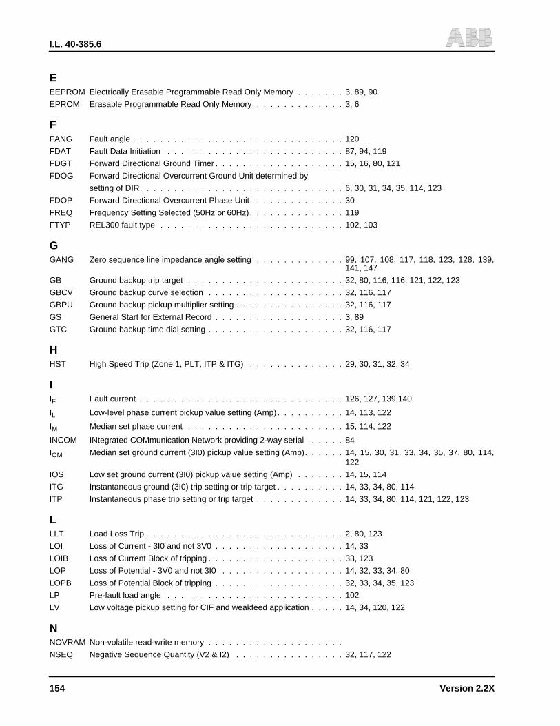
I.L. 40-385.6
154 Version 2.2X
EEEPROM Electrically Erasable Programmable Read Only Memory . . . . . . . 3, 89, 90
EPROM Erasable Programmable Read Only Memory . . . . . . . . . . . . . 3, 6
FFANG Fault angle . . . . . . . . . . . . . . . . . . . . . . . . . . . . . . . 120
FDAT Fault Data Initiation . . . . . . . . . . . . . . . . . . . . . . . . . . 87, 94, 119
FDGT Forward Directional Ground Timer . . . . . . . . . . . . . . . . . . . 15, 16, 80, 121
FDOG Forward Directional Overcurrent Ground Unit determined by
setting of DIR. . . . . . . . . . . . . . . . . . . . . . . . . . . . . . 6, 30, 31, 34, 35, 114, 123
FDOP Forward Directional Overcurrent Phase Unit. . . . . . . . . . . . . . 30
FREQ Frequency Setting Selected (50Hz or 60Hz) . . . . . . . . . . . . . . 119
FTYP REL300 fault type . . . . . . . . . . . . . . . . . . . . . . . . . . . 102, 103
GGANG Zero sequence line impedance angle setting . . . . . . . . . . . . . 99, 107, 108, 117, 118, 123, 128, 139,
141, 147
GB Ground backup trip target . . . . . . . . . . . . . . . . . . . . . . . 32, 80, 116, 116, 121, 122, 123
GBCV Ground backup curve selection . . . . . . . . . . . . . . . . . . . . 32, 116, 117
GBPU Ground backup pickup multiplier setting . . . . . . . . . . . . . . . . 32, 116, 117
GS General Start for External Record . . . . . . . . . . . . . . . . . . . 3, 89
GTC Ground backup time dial setting . . . . . . . . . . . . . . . . . . . . 32, 116, 117
HHST High Speed Trip (Zone 1, PLT, ITP & ITG) . . . . . . . . . . . . . . 29, 30, 31, 32, 34
IIF Fault current . . . . . . . . . . . . . . . . . . . . . . . . . . . . . . 126, 127, 139,140
IL Low-level phase current pickup value setting (Amp) . . . . . . . . . . 14, 113, 122
IM Median set phase current . . . . . . . . . . . . . . . . . . . . . . . 15, 114, 122
INCOM INtegrated COMmunication Network providing 2-way serial . . . . . 84
IOM Median set ground current (3I0) pickup value setting (Amp). . . . . . 14, 15, 30, 31, 33, 34, 35, 37, 80, 114,122
IOS Low set ground current (3I0) pickup value setting (Amp) . . . . . . . 14, 15, 114
ITG Instantaneous ground (3I0) trip setting or trip target . . . . . . . . . . 14, 33, 34, 80, 114
ITP Instantaneous phase trip setting or trip target . . . . . . . . . . . . . 14, 33, 34, 80, 114, 121, 122, 123
LLLT Load Loss Trip . . . . . . . . . . . . . . . . . . . . . . . . . . . . . 2, 80, 123
LOI Loss of Current - 3I0 and not 3V0 . . . . . . . . . . . . . . . . . . . 14, 33
LOIB Loss of Current Block of tripping . . . . . . . . . . . . . . . . . . . . 33, 123
LOP Loss of Potential - 3V0 and not 3I0 . . . . . . . . . . . . . . . . . . 14, 32, 33, 34, 80
LOPB Loss of Potential Block of tripping . . . . . . . . . . . . . . . . . . . 32, 33, 34, 35, 123
LP Pre-fault load angle . . . . . . . . . . . . . . . . . . . . . . . . . . 102
LV Low voltage pickup setting for CIF and weakfeed application . . . . . 14, 34, 120, 122
NNOVRAM Non-volatile read-write memory . . . . . . . . . . . . . . . . . . . .
NSEQ Negative Sequence Quantity (V2 & I2) . . . . . . . . . . . . . . . . 32, 117, 122

I.L. 40-385.6
Version 2.2X 155
OOFF 3-Pole trip, no reclosing . . . . . . . . . . . . . . . . . . . . . . . . 38
OS Out-of-Step . . . . . . . . . . . . . . . . . . . . . . . . . . . . . . 40
OPTI Opto Input for Input Test . . . . . . . . . . . . . . . . . . . . . . . 135, 151
OSB Enable/Disable out-of-step blocking. . . . . . . . . . . . . . . . . . 16, 17, 29, 40, 80, 114, 115, 118
OSC Oscillographic data . . . . . . . . . . . . . . . . . . . . . . . . . . 94, 119
OSOT Out-of-step block override timer (ms) . . . . . . . . . . . . . . . . . 118
PPANG Positive sequence line impedance angle setting . . . . . . . . . . . 39, 40, 99, 107, 108, 111, 117, 118, 123,
124, 126, 128, 139, 141, 147
PFAIL Power Supply Failure . . . . . . . . . . . . . . . . . . . . . . . . .
PFLC Pre-fault load current . . . . . . . . . . . . . . . . . . . . . . . . .
PFLV Pre-fault load voltage . . . . . . . . . . . . . . . . . . . . . . . . .
PLT/ENA Pilot enable (external switch) . . . . . . . . . . . . . . . . . . . . .
PLTG Pilot ground distance setting (ohms) . . . . . . . . . . . . . . . . . 34, 35, 80, 113, 121, 122
PLTP Pilot phase distance setting (ohms) . . . . . . . . . . . . . . . . . . 34, 80, 113, 121, 122
PONI Product Operated Network Interface . . . . . . . . . . . . . . . . . 2, 17
POTT Permissive Overreaching Transfer Trip . . . . . . . . . . . . . . . . 80, 120, 121
PROM Programmable Read Only Memory . . . . . . . . . . . . . . . . . . 3
PSME Power Supply Monitor Enable . . . . . . . . . . . . . . . . . . . . .
PT Potential Transformer . . . . . . . . . . . . . . . . . . . . . . . . .
PTRI Pilot Reclose Initiate for 3-pole Reclose RI2 . . . . . . . . . . . . . 120, 123
PUTT Permissive Underreaching Transfer Trip . . . . . . . . . . . . . . . 120, 121
RRAM Random Access Memory . . . . . . . . . . . . . . . . . . . . . . . 6, 7, 89, 90
RB Reclose Block . . . . . . . . . . . . . . . . . . . . . . . . . . . . . 3, 16, 35, 38, 39, 84, 89, 120
RCVR Receiver (external voltage or switch) . . . . . . . . . . . . . . . . . 80
RDOG Reverse Direction Overcurrent Ground determined by
the setting of DIRU (ZSEQ/NSEQ/DUAL)[ . . . . . . . . . . . . . . 30, 31, 34
REED B-1 Reed relay B-1 for trip seal-in . . . . . . . . . . . . . . . . . . . . .
REM Remote . . . . . . . . . . . . . . . . . . . . . . . . . . . . . . . .
RI Reclose Initiate . . . . . . . . . . . . . . . . . . . . . . . . . . . . 3, 16, 84, 120
RI1 Reclose Initiate-1 for Single-Pole Reclose . . . . . . . . . . . . . . 16, 38, 79, 89, 123, 125
RI2 Reclose Initiate-2 for 3-Pole Reclose . . . . . . . . . . . . . . . . . 16, 38, 79, 89, 123, 125
ROM Read-Only-Memory . . . . . . . . . . . . . . . . . . . . . . . . . .
RP Enable readouts in primary values . . . . . . . . . . . . . . . . . . 87, 119
RS1 Test function for simulating receipt of receiver 1 input . . . . . . . . 89
RS2 Test function for simulating receipt of receiver 2 input . . . . . . . .
RT Inner blinder setting (ohms) for 3-phase load restriction . . . . . . . 16, 40, 114
RU Outer blinder setting (ohms) for out-of-step option . . . . . . . . . . 17, 40, 114
RX1 Pilot channel receiver #1 input, same as RCVR#1 . . . . . . . . . . 90
RX2 Pilot channel receiver #2 input, same as RCVR#2 . . . . . . . . . . 90
SSBP Stub bus protection (89b) . . . . . . . . . . . . . . . . . . . . . . . 1, 3, 34, 84, 90, 122
SCF Stub Bus with standard Close-into-fault . . . . . . . . . . . . . . . . 34, 122
SCFT Stub Bus with CIF and Timer . . . . . . . . . . . . . . . . . . . . . 34, 122
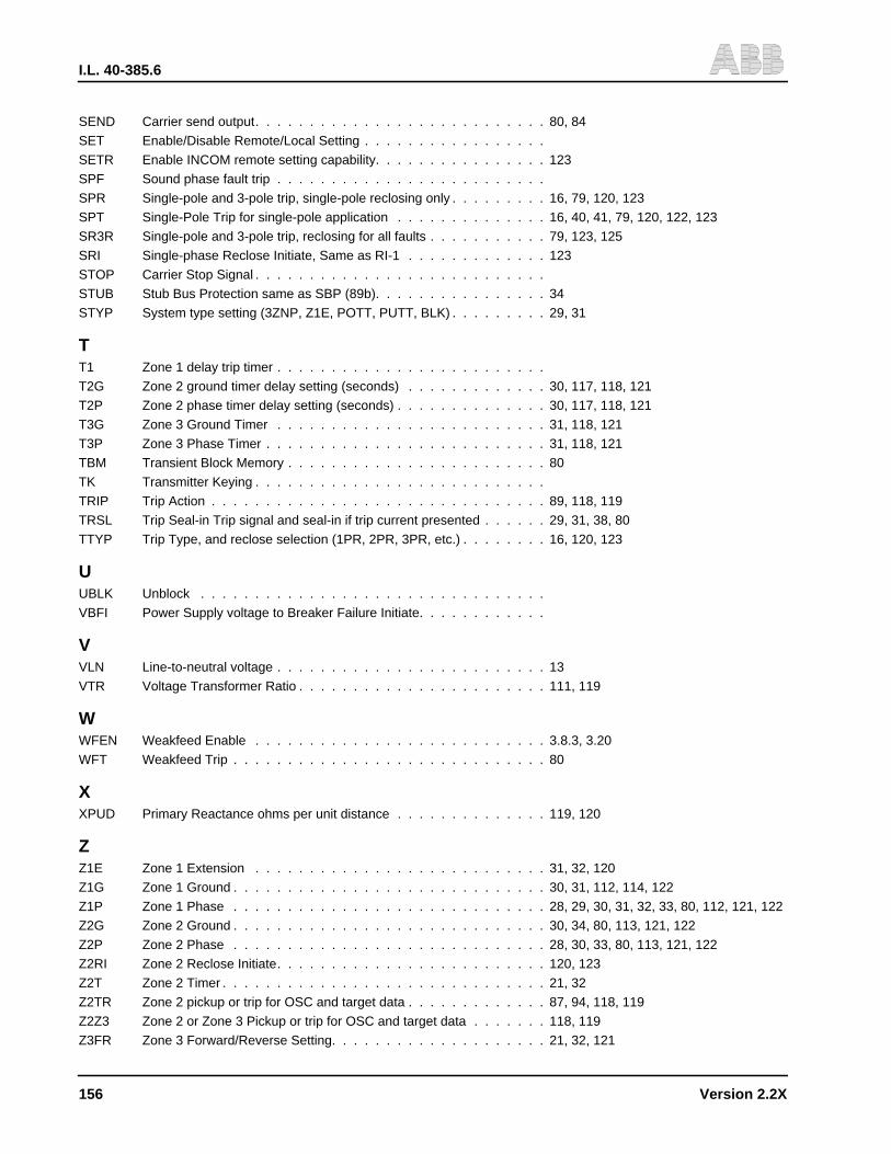
I.L. 40-385.6
156 Version 2.2X
SEND Carrier send output. . . . . . . . . . . . . . . . . . . . . . . . . . . 80, 84
SET Enable/Disable Remote/Local Setting . . . . . . . . . . . . . . . . .
SETR Enable INCOM remote setting capability. . . . . . . . . . . . . . . . 123
SPF Sound phase fault trip . . . . . . . . . . . . . . . . . . . . . . . . .
SPR Single-pole and 3-pole trip, single-pole reclosing only . . . . . . . . . 16, 79, 120, 123
SPT Single-Pole Trip for single-pole application . . . . . . . . . . . . . . 16, 40, 41, 79, 120, 122, 123
SR3R Single-pole and 3-pole trip, reclosing for all faults . . . . . . . . . . . 79, 123, 125
SRI Single-phase Reclose Initiate, Same as RI-1 . . . . . . . . . . . . . 123
STOP Carrier Stop Signal . . . . . . . . . . . . . . . . . . . . . . . . . . .
STUB Stub Bus Protection same as SBP (89b). . . . . . . . . . . . . . . . 34
STYP System type setting (3ZNP, Z1E, POTT, PUTT, BLK) . . . . . . . . . 29, 31
TT1 Zone 1 delay trip timer . . . . . . . . . . . . . . . . . . . . . . . . .
T2G Zone 2 ground timer delay setting (seconds) . . . . . . . . . . . . . 30, 117, 118, 121
T2P Zone 2 phase timer delay setting (seconds) . . . . . . . . . . . . . . 30, 117, 118, 121
T3G Zone 3 Ground Timer . . . . . . . . . . . . . . . . . . . . . . . . . 31, 118, 121
T3P Zone 3 Phase Timer . . . . . . . . . . . . . . . . . . . . . . . . . . 31, 118, 121
TBM Transient Block Memory . . . . . . . . . . . . . . . . . . . . . . . . 80
TK Transmitter Keying . . . . . . . . . . . . . . . . . . . . . . . . . . .
TRIP Trip Action . . . . . . . . . . . . . . . . . . . . . . . . . . . . . . . 89, 118, 119
TRSL Trip Seal-in Trip signal and seal-in if trip current presented . . . . . . 29, 31, 38, 80
TTYP Trip Type, and reclose selection (1PR, 2PR, 3PR, etc.) . . . . . . . . 16, 120, 123
UUBLK Unblock . . . . . . . . . . . . . . . . . . . . . . . . . . . . . . . .
VBFI Power Supply voltage to Breaker Failure Initiate. . . . . . . . . . . .
VVLN Line-to-neutral voltage . . . . . . . . . . . . . . . . . . . . . . . . . 13
VTR Voltage Transformer Ratio . . . . . . . . . . . . . . . . . . . . . . . 111, 119
WWFEN Weakfeed Enable . . . . . . . . . . . . . . . . . . . . . . . . . . . 3.8.3, 3.20
WFT Weakfeed Trip . . . . . . . . . . . . . . . . . . . . . . . . . . . . . 80
XXPUD Primary Reactance ohms per unit distance . . . . . . . . . . . . . . 119, 120
ZZ1E Zone 1 Extension . . . . . . . . . . . . . . . . . . . . . . . . . . . 31, 32, 120
Z1G Zone 1 Ground . . . . . . . . . . . . . . . . . . . . . . . . . . . . . 30, 31, 112, 114, 122
Z1P Zone 1 Phase . . . . . . . . . . . . . . . . . . . . . . . . . . . . . 28, 29, 30, 31, 32, 33, 80, 112, 121, 122
Z2G Zone 2 Ground . . . . . . . . . . . . . . . . . . . . . . . . . . . . . 30, 34, 80, 113, 121, 122
Z2P Zone 2 Phase . . . . . . . . . . . . . . . . . . . . . . . . . . . . . 28, 30, 33, 80, 113, 121, 122
Z2RI Zone 2 Reclose Initiate. . . . . . . . . . . . . . . . . . . . . . . . . 120, 123
Z2T Zone 2 Timer . . . . . . . . . . . . . . . . . . . . . . . . . . . . . . 21, 32
Z2TR Zone 2 pickup or trip for OSC and target data . . . . . . . . . . . . . 87, 94, 118, 119
Z2Z3 Zone 2 or Zone 3 Pickup or trip for OSC and target data . . . . . . . 118, 119
Z3FR Zone 3 Forward/Reverse Setting. . . . . . . . . . . . . . . . . . . . 21, 32, 121
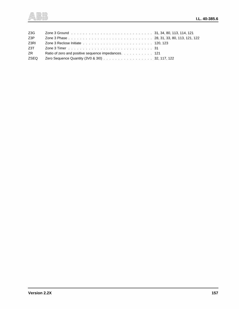
I.L. 40-385.6
Version 2.2X 157
Z3G Zone 3 Ground . . . . . . . . . . . . . . . . . . . . . . . . . . . . 31, 34, 80, 113, 114, 121Z3P Zone 3 Phase . . . . . . . . . . . . . . . . . . . . . . . . . . . . . 28, 31, 33, 80, 113, 121, 122Z3RI Zone 3 Reclose Initiate . . . . . . . . . . . . . . . . . . . . . . . . 120, 123Z3T Zone 3 Timer . . . . . . . . . . . . . . . . . . . . . . . . . . . . . 31ZR Ratio of zero and positive sequence impedances. . . . . . . . . . . 121ZSEQ Zero Sequence Quantity (3V0 & 3I0) . . . . . . . . . . . . . . . . . 32, 117, 122

I.L. 40-385.6
158 Version 2.2X
THIS PAGE RESERVED FOR NOTES
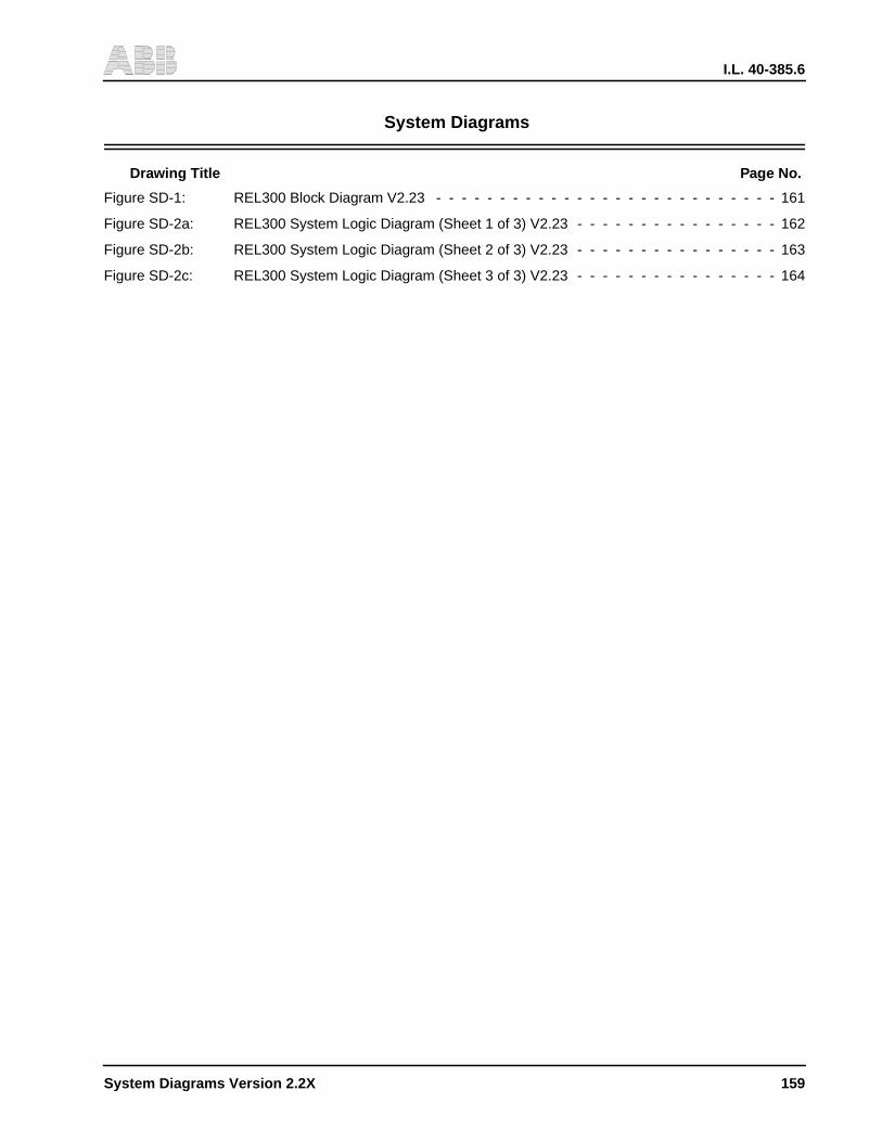
I.L. 40-385.6
System Diagrams Version 2.2X 159
System Diagrams
Drawing Title Page No.
Figure SD-1: REL300 Block Diagram V2.23 - - - - - - - - - - - - - - - - - - - - - - - - - - - 161
Figure SD-2a: REL300 System Logic Diagram (Sheet 1 of 3) V2.23 - - - - - - - - - - - - - - - - 162
Figure SD-2b: REL300 System Logic Diagram (Sheet 2 of 3) V2.23 - - - - - - - - - - - - - - - - 163
Figure SD-2c: REL300 System Logic Diagram (Sheet 3 of 3) V2.23 - - - - - - - - - - - - - - - - 164

I.L. 40-385.6
160 System Diagrams Version 2.2X
THIS PAGE RESERVED FOR NOTES