Embed Size (px)
Citation preview

ReinforcingBar Couplersfor the Construction Industry
CI/SfB (29) Et6
September 2012

2 Tel: +44 (0) 114 275 5224 www.ancon.co.uk
Coupler Selection 5-6
Typical Coupler Applications 7
Tapered Thread Standard Series 8-9
Tapered Thread Positional Series 10-11
Tapered Thread Transition Series 12
Tapered Thread Starter Bars 13
Tapered Thread Weldable Series 14
Tapered Thread Headed Anchors 15
Bartec Series 16-19
Bar X-L Series 20-23
MBT ET Series 24-25
MBT Transition Series 26
MBT Continuity Series 27-29
MBT Headed Anchors 30
MBT Electric Wrench 31
Other Ancon Products 31
Contents
Lapped joints are not always anappropriate means of connectingreinforcing bars. The use of lapscan be time consuming in termsof design and installation andcan lead to greater congestionwithin the concrete because ofthe increased amount of rebarused.
Ancon couplers can simplify thedesign and construction ofreinforced concrete and reducethe amount of reinforcementrequired.
Lapped joints are dependentupon the concrete for loadtransfer. For this reason anydegradation in the integrity of
the concrete could significantlyaffect the performance of thejoint. The strength of amechanical splice is independentof the concrete in which it islocated and will retain itsstrength despite loss of cover asa result of impact damage orseismic event.
The Ancon range of reinforcingbar couplers is the mostcomprehensive available andincludes tapered threaded,parallel threaded andmechanically bolted couplers.
Reinforcing Bar CouplersSimplify the design and construction of concrete

3
Comprehensive Range Eurocode 2 compliant Simplify design andconstruction
Reduce amount ofreinforcement required
Dedicated salessupport
Technical approvalTA1-B 5015 for
Tapered Thread Couplers
Available through majorrebar stockists and
approved distributors
ISO 9001, ISO 14001,OHSAS 18001

Reinforcing Bar Couplers
Sales SupportAncon’s ‘Products for Structural Concrete’ Division provides assistance for clients who requireproducts which are used in structural concrete construction. These include, but are not restrictedto, reinforcing bar couplers, reinforcement continuity systems, punching shear reinforcement andshear load connectors. A dedicated team is available to offer technical advice, pricing informationand guidance on the selection of the most appropriate product for a specific application.Enquiries from overseas are also dealt with by the PSC team. To contact the team please [email protected] or call +44 (0) 114 275 5224.
The information in this literature is given as aguide only. Please refer to Ancon installationprocedures, instructions and operating manualsfor more specific details on these products.
Characteristic Strengths of High YieldReinforcing BarDiameter Area Fy(kN)(mm) (mm2) 500N/mm2
10 78.5 39.3
12 113 56.5
14 154 77.0
16 201 100.5
18 254 127.2
20 314 157.0
22 380 190.0
25 491 245.5
26 531 265.4
28 616 307.8
30 707 353.4
32 804 402.1
34 908 453.9
36 1,018 509.0
40 1,256 628.3
50 1,963 981.7
4 Tel: +44 (0) 114 275 5224 www.ancon.co.uk
For many years the use of mechanical couplers to join reinforcing bars has been regarded as a means ofreducing the use of long bars. Engineers and contractors now recognise the benefits of using couplers toaccelerate the speed of construction, increase productivity and simplify design details.

Tapered ThreadThe Tapered Thread coupler is designed to suitthe majority of applications which require thejoining of reinforcing bars. The ends of the rebar are cut square and a tapered thread is cutonto the bar to suit the tapered thread coupler.The sleeve is tightened onto the threaded barend using a calibrated torque wrench.
MBTMBT couplers are suitable where it is notconvenient to have the bar ends prepared forparallel thread or tapered thread couplers.The bars are supported within the coupler ontwo serrated saddles. Bars are locked inplace by a series of special lockshear bolts,the heads of which shear off when thepredetermined tightening torque is reached,providing a visual check of correct installation.
BartecThe Bartec system is one of the smallestcouplers in the Ancon range. The ends of thebars are enlarged and a parallel thread is cutonto the ends to suit the threaded coupler.The coupler is assembled using a pipe or chainwrench. Calibrated wrenches are not necessary.
Bar X-LBar X-L couplers provide a full strength jointand are the smallest couplers in the Anconrange. They are particularly appropriate forapplications where fatigue is an issue. Theends of the bars are cut square and marginallyenlarged. A parallel thread is then rolled ontothe ends to suit the threaded sleeve. Thecoupler is installed using a pipe or chainwrench. Calibrated torque wrenches are notrequired. This product is only available inselected territories in mainland Europe.Please contact Ancon for locations.
Availability of CouplersBar Diameter (mm) 10 12 14 16 18 20 22 24 25 26 28 30 32 34 36 40 50
Tapered Thread Standard
Tapered Thread Positional
Tapered Thread Transition
Tapered Thread Starter Bars
Tapered Thread Weldable
Tapered Thread Anchor
Bartec
Bar X-L
MBT ET
MBT Transition
MBT Continuity
MBT Anchor
� � � � � � � � � � � � � � � �
� � � � � � � � � � � � � � �
� � � � � � � � � � � � � �
� � � � � � � � �
� � � � � � � � � � � � � �
� � � � � � � � � � � � � � �
� � � � � � � � �
� � � � � � � � � � � � � �
� � � � � � � � � � � � � �
� � � � � � � � �
� � � � � �
� � � � � � � � � � � � � � �
5
Coupler Selection
The four types of Anconreinforcing bar couplers requiredifferent fixing methods.This, together with the quantityto be fixed and the location,will determine which is the mostappropriate coupler for aparticular situation.

Reinforcing Bar Couplers
Coupler SelectionRange Tapered Thread Bartec Bar X-L MBTType Standard Positional Transition Weldable HA Type A Type B Type C Type A Type B Type C ET Transition Continuity HA
Bar Dia. (mm) 12-50 12-50 12-50 12-50 12-50 12-50 12-50 12-50 12-50 12-50 12-50 10-40 10-40 10-40 10-40
Bar End Prep Threaded Threaded Threaded Threaded Threaded Threaded Threaded Threaded Threaded Threaded Threaded No No No No
Bar Rotation Yes No Yes Yes Yes Yes Limited No Yes Limited No No No No No
Installation Torque Wrench Wrench Wrench Wrench or Nut RunnerMethodMinimum Full Strength up to 575N/mm2 Full Strength up to 650N/mm2 Full Strength up to 650N/mm2 Full Strength up to 575N/mm2
TensileCapacityApprovals BS8110 BS8110 BS8110 BS8110
CARES TA1-B ACI 349 DET NORSKE VERITAS BS5400DIBt Approval No Z-1.5-179 ASME III DIV 2 (ACI 359) (X-L 25, 32) BBA 98/R102
12, 14, 16, 20, 25, 28, 32, 40 ACI 318 ASME III DIV 2 (ACI 359) ET10, 12, 16, 20, 25, 32, 40AFCAB Certified No M07/006 CSA CAN 3 – N2872 ACI 349 (36, 43, 57) ACI 318
Sizes 12, 14, 16, 20, 25, 32, 40 DIN 1045 German CodeDIBt Approval No Z-1.5-10
ET 10, 12, 14, 16, 20, 25, 28
{ }
{ }
{ }{ }
Coupler SpecificationAncon Couplers can be specified using the part numbers which areincluded in the tabulated data in each section of this brochure.
The following examples show how each type of coupler should bespecified when using 20mm bar.
Type of Coupler Reference Page
Tapered Thread Standard TTS20 8
Tapered Thread Positional TTP20 10
Tapered Thread Transition TTT20 12
Tapered Thread Starter Bar TTSB20 13
Tapered Thread Weldable TTW20 14
Tapered Thread Headed Anchor TTH20 15
Bartec Type A BT20/A 16
Bartec Type B BT20/B 16
Bartec Type C BT20/C 16
Bar X-L Type A XL20/A 20
Bar X-L Type B XL20/B 20
Bar X-L Type C XL20/C 20
MBT ET Series ET20 24
MBT Transition Series ET20/16 26
MBT Continuity Series C20 27
MBT ET Headed Anchor ETHA20 30
If you require any further assistance please contactAncon Building Products.
6 Tel: +44 (0) 114 275 5224 www.ancon.co.uk

Typical CouplerApplication GuideThe following table provides a guide whenselecting the most appropriate couplers forspecific applications. Recommendations arebased upon typical usage. Please contactAncon for further assistance on the correctselection and specification of couplers.
Application Tapered Thread Bartec Bar X-L MBT
Wall to slab connection
Wall to pre-cast beam connection
Column construction
Extension / repairs to existing structures
Pre-cast element to pre-cast element connection
Closing of access openings
Rebar cage pre-fabrication
Hook bars to pile connection
Fatigue applications
Bar end terminations
� � �
� � �
� � � �
�
� � � �
� � � �
� � � �
�
� � �
� �
7

Tapered ThreadThe Ancon range of Tapered Thread couplers is designed to suit themajority of applications which call for the joining of reinforcing bars.Available to suit bar sizes 12mm to 50mm, the couplers are installedquickly and easily on site without the need for specially trainedpersonnel or specialised, expensive machinery.
The compact design of each coupler ensures suitability for use in confined situations where spaceis restricted or where the loss of cover must be minimised. The couplers are normally suppliedfitted to the end of threaded bar, requiring only the engagement and tightening of the adjoining baron site. In order to ensure correct installation, Ancon Building Products specifies the use of atorque wrench. The range of Tapered Thread couplers is available through major rebar suppliers.Please contact Ancon for further details.
Standard CouplerThe Standard Tapered Thread coupler is suitable for connecting two bars of the same diameter,where one bar can be rotated. It comprises an internally threaded sleeve with two right handthreads which are tapered towards the middle of the coupler. The bar ends are square cut anda tapered thread is cut onto the bar. A nominal allowance of +25mm should be allowed perthreaded bar end for square cutting the bar end.
The couplers are generally torqued onto the reinforcing bar in the bar threading shop, the internalthreads protected by plastic end caps. The threaded ends of the continuation bar are protectedby plastic thread protectors.
Engagement of the bar within the coupler is simplified by the tapered thread design which aidsalignment. When the bar is fully engaged within the coupler, the continuation bar is tightened usinga torque wrench.
The Ancon Standard Tapered Thread coupler is designed for use in concrete structures to meetthe requirements of BS EN 1992-1-1: 2004 (Eurocode 2) and BS 8110 for mechanical splices.They are designed to achieve failure loads in excess of 115% of the characteristic strength ofgrade 500 rebar.
Reinforcing Bar Couplers
Bar Diameter (mm) 12 14 16 18 20 22 24 25 26 28 30 32 34 36 40 50
External Dia. d 22 22 25 28 30 32 36 36 40 42 45 48 55 55 60 70
Coupler Length l 58 64 70 72 74 81 87 90 94 100 106 112 119 126 138 170
Weight (kg) 0.13 0.12 0.17 0.22 0.25 0.31 0.43 0.43 0.59 0.66 0.82 0.99 1.50 1.50 1.90 2.91
Torque (Nm) 60 85 110 135 165 205 250 265 270 275 280 285 295 305 330 350
Part No. TTS12 TTS14 TTS16 TTS18 TTS20 TTS22 TTS24 TTS25 TTS26 TTS28 TTS30 TTS32 TTS34 TTS36 TTS40 TTS50
Standard Coupler Dimensions
Testing and ApprovalsThe Standard range of Tapered Thread couplers has been tested and approved by UK CARES to showcompliance with the requirements of BS EN 1992-1-1: 2004 (Eurocode 2) and BS 8110.
The most common sizes have been tested and approved by the DIBt and are covered by Approval No Z-1.5-179.
Ancon Standard Tapered Thread Couplers, sizes 12, 14, 16, 20, 25, 32 and 40, are AFCAB Certified.Note: Not all coupler types and sizes are relevant to the national approvals shown. For details of coupler types and sizes relevant to eachnational approval please refer to the relevant approval document, which is available on request.
d
l
8 Tel: +44 (0) 114 275 5224 www.ancon.co.uk

InstallationTapered Thread Standard Series
Continue to screw the bar into the coupler until tight.
After casting the concrete and when ready toextend, remove the plastic end cap from thecoupler. Position the continuation bar in thesleeve and rotate the bar into the coupler.
The coupler is normally supplied fixed to thereinforcing bar, ready to be installed and castin concrete.
To ensure correct installation, tighten the joint tothe specified torque using a calibrated torquewrench on the continuation bar. Tighteningtorques are shown in the table opposite.
1
4
2
3
9

lc
ls
lm
lo
le
Inla
li d2
Female component
Male componentLocknut
Positional CouplerThe Ancon Tapered Thread Positional coupler is designed to be usedin applications in which neither bar can be rotated. Having a degreeof adjustability, the Positional coupler can also be used as a closerbetween two fixed bars.The Positional coupler comprises three components, a male section, a female section and alocking nut. The male component has an internal tapered thread and an extended external parallelthread. The female component has a parallel thread and a tapered thread, both of which areinternal. A locknut is used to secure the connection when the correct degree of adjustability hasbeen achieved. All components, including the locknut must be tightened using a torque wrench.
Plastic thread protectors are used to prevent damage to the threaded bar ends and the internalthreads of the couplers are protected by plastic end caps. A nominal allowance of +25mm shouldbe allowed per threaded bar end for square cutting the bar end.
Testing & ApprovalsThe Positional range of Tapered Thread couplers has been tested and approvedby UK CARES to show compliance with the requirements of BS EN 1992-1-1:2004 (Eurocode 2) and BS 8110. The most common sizes have been tested andapproved by the DIBt and are covered by Approval No Z-1.5-179. Ancon TaperedThread Positional Couplers, sizes 12, 14, 16, 20, 25, 32 and 40, are AFCAB Certified.Note: Not all coupler types and sizes are relevant to the national approvals shown. For details of coupler types and sizes relevant to each national approval please refer to the relevant approval document, which is available on request.
Reinforcing Bar Couplers
Position the continuation bar as near aspossible to the coupler fitted to the cast-in bar.
Run the male component and locknut onto thecontinuation bar until fully engaged.
2
3
InstallationTapered Thread PositionalSeries1
Bar Diameter (mm) 12 14 16 18 20 22 25 26 28 30 32 34 36 40 50External Dia. d1 25 25 30 36 36 42 48 46 50 55 55 60 70 70 85External Dia. d2 22 22 25 28 30 32 36 40 42 45 48 55 55 60 70Female Sleeve Length ls 84 89 95 95 112 120 132 136 137 147 153 164 190 190 233Locknut Length ln 13 13 13 13 13 13 13 13 13 15 15 15 15 15 16Closed Length lc 138 150 155 156 180 191 207 213 218 234 243 261 296 296 359Max. Open Length lo 178 190 196 195 231 245 266 273 274 295 305 328 373 374 454Bar Insertion Prior to Engagement li 9 12 15 18 8 11 16 18 22 25 28 31 34 40 54Bar Insertion Full Engagement le 26 29 32 32 33 37 42 44 47 50 53 56 58 66 82Adjustable Length la 23 23 24 25 26 28 34 34 34 36 37 42 54 52 67Max Distance between Bar Ends lm 126 124 132 131 165 171 182 185 174 195 199 216 257 242 290Weight (kg) 0.44 0.67 0.67 0.95 1.12 1.56 2.21 2.18 2.30 3.34 3.51 4.66 6.83 6.91 11.96Coupler Torque (Nm) 60 85 110 135 165 205 265 270 275 280 285 295 305 330 350Locknut Torque (Nm) 20 25 30 40 50 60 70 80 80 85 90 100 105 110 130Part No. TTP12 TTP14 TTP16 TTP18 TTP20 TTP22 TTP25 TTP26 TTS28 TTP30 TTP32 TTP34 TTP36 TTP40 TTP50
Positional Coupler Dimensions
The female section of the positional coupler isnormally cast flush in the concrete. The installermust take care to protect the internal threadsand prevent the ingress of concrete. Once castand ready to extend, the male end completewith locknut can be screwed into place.
10 Tel: +44 (0) 114 275 5224 www.ancon.co.uk
d1

Using a torque wrench tighten the malecomponent on the continuation bar to thespecified torque, whilst holding thecontinuation bar with a second wrench.
Run the locknut along the threaded barrel ofthe male component to abut the femalesection. Using the torque wrench, tighten the locknut to the specified torque. Tighteningtorques are shown in the table opposite.
At this point the groove in the parallel threadedsection of the male component must becompletely covered by the locknut. If any partof the groove is visible beyond the locknut, thedegree of adjustability has been exceeded andthe installation is incorrect.
Incorrect Installation
Groove is completely hidden within locknut
4
5
Correct Installation
Groove is protruding from locknut
11
d
Reinforcing Bar Couplers
After casting of the concrete and when readyto extend, remove the plastic end cap from thecoupler. Position the continuation bar in thesleeve and rotate the bar into the coupler.
Continue to screw the bar into the coupler until tight.
To ensure correct installation, tighten the joint tothe specified torque using a calibrated torquewrench on the continuation bar. Tighteningtorques are shown in the table below.Note: In the event of the coupler being supplied fixed tothe smaller bar it is necessary to ensure that whentightening the larger continuation bar, the force is nottransmitted through the smaller bar.
2
3
4
1
The coupler is normally supplied fixed to areinforcing bar, ready to be installed and castin concrete.
Transition CouplerThe Ancon Tapered ThreadTransition coupler is used to joinreinforcing bars of differentdiameters where one couplercan be rotated.With all the benefits of the Standard range,
Transition couplers are designed to achievefailure loads greater than 115% of the
characteristic strength of thesmaller diameter grade 500reinforcing bar.The Transition couplercomprises an internallythreaded sleeve with tworight hand threads both ofwhich are tapered towardsthe middle of the coupler.
The diameter of each threadcorresponds to the appropriate bar size. A nominal +25mm should be allowed perthreaded bar end for square cutting the bar end.
InstallationTapered Thread TransitionSeries
Testing & ApprovalsThe Transition range of TaperedThread couplers has been testedand approved by UK CARESto show compliance withthe requirements ofBS EN 1992-1-1: 2004(Eurocode 2) and BS 8110.
Tapered Thread Transitioncouplers have also beenapproved up to size 32/40 bythe DIBt and are covered byApproval No Z-1.5-179.
Ancon Tapered Thread Transition couplers, sizes12/14, 12/16, 14/16, 16/20, 20/25, 25/32 and32/40, are AFCAB certified.Note: Not all coupler types and sizes are relevant to thenational approvals shown. For details of coupler types andsizes relevant to each national approval please refer to therelevant approval document, which is available on request.
d
l
Transition Coupler Dimensions
Bar Diameter 12/14 12/16 14/16 16/18 16/20 18/20 20/22 20/25 20/28 22/26 25/28 25/32 26/30 28/32 30/34 32/40 34/40 40/50
External Dia. d 22 25 25 28 30 30 32 36 42 40 42 48 45 48 55 55 60 70
Coupler Length l 65 72 71 75 78 77 82 90 91 92 99 112 104 110 117 138 133 170
Weight (kg) 0.14 0.21 0.19 0.25 0.30 0.28 0.32 0.48 0.65 0.62 0.72 1.11 0.87 1.02 1.59 1.62 1.97 3.31
Torque (Nm) 60/85 60/110 85/110 110/135 110/165 135/165 165/205 165/265 165/275 205/270 265/275 265/285 270/280 275/285 280/295 285/330 295/330 330/350
Part No. TTT12/14 TTT12/16 TTT14/16 TTT16/18 TTT16/20 TTT18/20 TTT20/22 TTT20/25 TTT20/28 TTT22/26 TTT25/28 TTT25/32 TTT26/30 TTT28/32 TTT30/34 TTT32/40 TTT34/40 TTT40/50
12 Tel: +44 (0) 114 275 5224 www.ancon.co.uk

Starter Bar SystemThe Ancon Starter Bar system isdesigned to increase the speedof construction by eliminating theneed to cut or drill formwork atconstruction joints wherecontinuity of reinforcement isrequired.Incorporating the Ancon tapered threadcoupler, approved by UK CARES, the systemsimplifies design and is ideal for use withslipforming.
The starter bar system comprises two elements.The female section consists of a threaded barconnected to a tapered thread coupler. A nailplate is fixed to the end of the coupler and isheld in place by a plastic end cap. This preventsingress of concrete until the continuation bar isfixed. The male section comprises a straight barthreaded at one end to allow connection to thecoupler after striking the formwork and removingthe end cap and nail plate. In order to ensurecorrect installation the continuation bar istightened using a calibrated torque wrench.
InstallationThe coupler is normally supplied fixed to thereinforcing bar. Upon removal of the plasticend cap, position the nail plate, which issupplied separately, on the end of the couplerto enable it to be fixed flush to the formwork.Secure the nail plate by replacing the end cap.Tie the starter bar assembly to the fixed barand position against the formwork. Nail theassembly to the formwork.
After casting the concrete and striking theformwork, remove the end cap and nail plateand place the continuation bar in the couplerand rotate until tight. To ensure correctinstallation tighten the rebar to the specifiedtorque using a calibrated wrench on thecontinuation bar. Tightening torques are shownin the following tables.
Bar Diameter 12 14 16 18 20 22 24 25 32
System Length (Bar with coupler) 660 765 870 975 1075 1185 1285 1340 1715
Coupler Length l 58 64 70 72 74 81 87 90 112
Coupler External Dia. d 22 22 25 28 30 32 36 36 48
Nail Plate Dia. d1 70 70 70 70 70 70 90 90 90
Torque (Nm) 60 85 110 135 165 205 250 265 285
Part No. TTSB12F TTSB14F TTSB16F TTSB18F TTSB20F TTSB22F TTSB24F TTSB25F TTSB32F
The threaded bar lengths in the table above are minimum lap lengths. Longer bars are available upon request.
d
l
d1
Starter Bar Dimensions
Starter Bar
Bar Diameter 12 14 16 18 20 22 24 25 32
Bar Length 625 730 830 935 1035 1140 1240 1290 1655
Torque (Nm) 60 85 110 135 165 205 250 265 285
Part No. TTSB12M TTSB14M TTSB16M TTSB18M TTSB20M TTSB22M TTSB24M TTSB25M TTSB32M
The threaded bar lengths in the table above are minimum lap lengths. Longer bars are available upon request.
Threaded Continuation Bar
13

Reinforcing Bar Couplers
The coupler must first be welded to thesteelwork.
1
Rotate the bar into the coupler until tight.
3
4
Installation
When ready to extend, remove the plastic end cap and position the continuation bar intothe sleeve.
2
To ensure correct installation, tighten the joint tothe specified torque using a calibrated torquewrench on the continuation bar. Tighteningtorques are shown in the table below.
Bar Diameter 12 14 16 18 20 22 25 26 28 30 32 34 40 50
External Dia. d 25 30 30 32 36 40 48 50 50 55 55 60 70 85
Coupler Length l 35 38 42 44 47 52 57 60 63 69 72 78 89 110
Weight (kg) 0.11 0.17 0.18 0.20 0.28 0.38 0.63 0.72 0.72 0.97 0.97 1.28 1.97 3.51
Torque (Nm) 60 85 110 135 165 205 265 270 275 280 285 295 330 350
Part No. TTW12 TTW14 TTW16 TTW18 TTW20 TTW22 TTW25 TTW26 TTW28 TTW30 TTW32 TTW34 TTW40 TTW50
Tapered Thread Weldable CouplersAncon Tapered Thread Weldable couplers provide a convenientmeans of connecting reinforcing bars to structural steel plates orsections.Shorter than the standard coupler, it has a tapered thread at one end. The other end is weldeddirectly to the steel. The couplers are produced in either steel grade Type 1045 to ASTM A576 orType 150M19 steel to BS970.
The Tapered Thread Weldable coupler is suitable for welding to structural steels, Grade S275 or Grade S355. The load conditions at the connection must be determined by the designer alongwith the type and size of weld required. Another important consideration is the type of electrode to be used, which must be matched to the properties of the plate and tube, and to the siteconditions under which the welding will be undertaken. Welders should be qualified for the type of weld required.
For further assistance and technical information please contact Ancon Building Products.
Testing & ApprovalsThe most common sizes of Tapered Thread Weldable couplers have beentested and approved by the DIBt and are covered by Approval No Z-1.5-179.
Ancon Tapered Thread Weldable Couplers, sizes 12, 14, 16, 20, 25, 32and 40, are AFCAB Certified.Note: Not all coupler types and sizes are relevant to the national approvals shown. For details of coupler types and sizes relevant to each national approval please referto the relevant approval document, which is available on request.
d
l
Weldable Coupler Dimensions
14 Tel: +44 (0) 114 275 5224 www.ancon.co.uk
Torque Values (Nm)
Torque Wrenches for Couplers and Locknuts
Part No. E879008 E879009 E879010
Torque (Nm) 60 - 285 85 - 350 20 - 90
Torque Wrenches
Bar Diameter 12 14 16 18 20 22 24 25 26 28 30 32 34 36 40 50
Standard Coupler 60 85 110 135 165 205 250 265 270 275 280 285 295 305 330 350
Positional Coupler 60 85 110 135 165 205 250 265 270 275 280 285 295 305 330 350
Positional Locknut 20 25 30 40 50 60 65 70 80 80 85 90 100 105 110 130
Bar Diameter 12/14 12/16 14/16 16/18 16/20 18/20 20/22 20/25 20/28 22/26 25/28 25/32 26/30 28/32 30/34 32/40 34/40 40/50
Transition Coupler 60/85 60/110 85/110 110/135 110/165 135/165 165/205 165/265 165/275 205/270 265/275 265/285 270/280 275/285 280/295 285/330 295/330 330/350
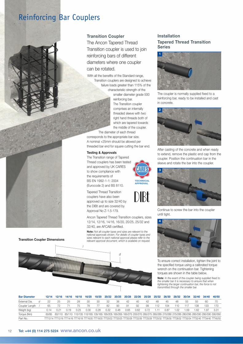
Bar Diameter 12 14 16 18 20 22 24 25 26 28 30 32 34 36 40
External Dia. d 40 45 50 55 65 70 80 80 85 90 100 110 115 120 135
External Dia. d1 - - - - - - - - - 78 78 78 78 78 78
Coupler Length l 27.0 30.0 33.0 35.0 35.0 38.5 42.5 43.5 45.0 46.5 50.0 53.5 56.0 60.5 67.5
Coupler Length l1 - - - - - - - - - 21.5 25.0 28.5 30.0 35.5 42.5
Weight (kg) 0.25 0.34 0.46 0.61 0.83 1.06 1.54 1.57 1.84 1.86 2.23 2.81 3.11 3.62 5.17
Torque (Nm) 60 85 110 135 165 205 250 265 270 275 280 285 295 305 330
Part No. TTH12 TTH14 TTH16 TTH18 TTH20 TTH22 TTH24 TTH25 TTH26 TTH28 TTH30 TTH32 TTH34 TTH36 TTH40
Note: Where tapered thread headed anchors are used, the compressive strength of the concrete shall not be less than strength grade C32/40 (cylinder/cube).
Tapered Thread Headed AnchorsThe Tapered Thread Headed Anchor providesan alternative method of achieving rebar endanchorage within concrete.Anchorage of rebars within a concrete section is traditionallyachieved by means of creating a long hooked end on the rebar.This can lead to problems when positioning the bar and canincrease congestion. It can ultimately result in larger thannecessary concrete sections at the location of the hooked ends.
Consisting of an oversized coupler, the Tapered Thread HeadedAnchor carries the full tension load of the bar when it is bearingagainst the concrete. The Headed Anchor removes the needfor hooked rebar and subsequently reduces congestion andsimplifies bar placement. This in turn increases speed ofconstruction and gives greater flexibility in design. Typicalapplications include pile caps and beam to column connections.
AccessoriesThreading MachineThe Ancon threading machine provides afast, simple and reliable threading operation.The machine is compact, making it completelyportable and easy to locate. It is of a robustdesign to provide a long, low maintenance life.
Threading machines are generally located instockists’ yards. For larger projects Anconmachines can be made available for hire.Please contact Ancon for further information.
Training on the correct usage of the threadingmachine is provided by Ancon technicians.
Machine ConsumablesThe following consumables are available:Chaser SetsChaser sets are available on a regrindable ordisposable basis. Each set can be reground upto 3 times in order to extend cutting life. Pleasecontact Ancon Building Products for details.
CoolantAncon Building Products recommends the useof Solmaster EPS or a similar water basedcoolant.
Thread ProtectorsPlastic sleeves are available to protect thetapered threads on reinforcing bars.
Torque Wrenches In order to ensure the correct assembly oftapered thread couplers the use of a calibratedtorque wrench is essential. Details of wrenchesare included in the table below. Each wrench issupplied with a certificate of calibration.
Torque Wrench CalibrationA calibration service for wrenches purchasedfrom Ancon is available. Please contact Anconfor further details.
d dd1
l
l1
Bar Diameters28-40mm
Bar Diameters12-26mm
l
Tapered Thread Headed Anchor Dimensions
Torque Wrench
Testing & ApprovalsThe most common sizes ofHeaded Anchors have beentested and approved by the DIBtand are covered by ApprovalNo Z-1.5-179.
Ancon Headed Anchors,sizes 12, 14, 16, 20,25, 32 and 40, areAFCAB Certified.
Note: Not all coupler types and sizes are relevant to thenational approvals shown. For details of coupler typesand sizes relevant to each national approval please referto the relevant approval document, which is available onrequest.
15

The end of each bar tobe joined is cut squareand enlarged by coldforging. This increases
the core diameter of the bar to ensure that thejoint is stronger than the bar.
Parallel metric threads are cut onto theenlarged ends. The threaded end is then prooftested to a force equal to the characteristicyield strength of the bar. A nominal allowanceof +50mm per threaded bar end should bemade for cutting square and cold forging.
Reinforcing Bar Couplers
Bartec Type BThe Bartec Type B uses the same coupler asthe Type A system, but one bar is threaded fora full coupler length. It is used for applicationswhere it is difficult but not impossible to rotatethe continuation bar.
Bartec Type CThe Bartec Type C system has an additionallocknut and is used where the continuation barcannot be rotated. The continuation bar isthreaded for the full coupler length plus thelength of the locknut.
Bartec Type AThe Bartec Type A system utilises internallythreaded couplers with a single right handthread and is suitable for applications wherethe continuation bar can be rotated. The endsof the bars are upset and threaded for half thelength of the coupler.
l
d
Bartec Dimensions
2tt
t
t2t
2/3 t2 2/3 t
2tt
2t
The threaded ends of the bars are protected byan external plastic sheath. Couplers, which areusually supplied attached to the bar, have theirinternal threads protected by an internal plasticend cap. For certain applications, especiallywhere Bartec is being used in deep pours,
the coupler end caps may not prevent theingress of concrete fines. For these applications,further protection may be required.
Bartec couplers are also available to join barsof different diameters. For further informationplease contact Ancon Building Products.
Bar Diameter 12 16 20 25 28 32 36 40 50
External Dia. d 21 26 32 40 45 50 57 62 77
Coupler Length l 32 40 48 60 66 72 84 90 112
Thread Size M16 M20 M24 M30 M33 M36 M42 M45 M56
Thread Pitch 2.0 2.5 3.0 3.5 3.5 3.0/4.0* 4.5 4.5 5.5
Weight (kg) 0.04 0.09 0.16 0.32 0.43 0.58 0.87 1.13 2.17
Part No Type A BT12/A BT16/A BT20/A BT25/A BT28/A BT32/A BT36/A BT40/A BT50/A
Part No Type B BT12/B BT16/B BT20/B BT25/B BT28/B BT32/B BT36/B BT40/B BT50/B
Part No Type C - BT16/C BT20/C BT25/C BT28/C BT32/C BT36/C BT40/C BT50/C*Dependent on geographical location. Please contact Ancon for further details.
16 Tel: +44 (0) 114 275 5224 www.ancon.co.uk
BartecBartec couplers produce a full strength joint yet they are among the smallest in the Ancon range,best suited to large scale projects requiring a high volume of couplers.

Nominal Yield Ultimate Elongation FailureBar Size Stress Stress % ModeDia. mm (N/mm2) (N/mm2)
16 531 587 18 Bar Break
20 518 596 20 Bar Break
25 522 625 18 Bar Break
32 484 604 20 Bar Break
40 512 629 18 Bar Break
50 510 669 17 Bar Break
Two Stage ConstructionIn two stage construction utilising Types B andC couplers, it is essential to form a pocket inthe face of the first stage concrete. This willcreate the space for the coupler to run onto thethread of the fixed reinforcing bar.
A pocket former is screwed onto the end of thebar and cast flush with the face of the concrete.
Mobile Bar End Preparation FacilityBartec threading equipment is generallyestablished in the rebar supplier’s premisesand couplers are usually supplied pre-fixed tothe threaded bar ends.
On large contracts where bar end preparationcan be carried out on site, equipment can bemade available for hire. It should be noted that the hirer will need to provide sufficientpower, air, rebar support tressles and cranehandling facilities.
Testing & ApprovalsBartec couplers are designed andmanufactured in accordance with BS EN ISO9001 and comply in all respects to BS EN1992-1-1: 2004 (Eurocode 2) and BS 8110when used with reinforcing bar to BS 4449.Full destructive tests have been carried out toshow compliance with the following codes:ACI 349; ASME III DIV 2 (ACI 359); ACI 318;CSA CAN 3 - N2872.
Typical Test Results
17

Reinforcing Bar Couplers
InstallationThe Bartec Type A System
Position the continuation bar with the coupleragainst the end of the first bar.
Rotate the coupler from the continuation bar toengage against the rear of the thread on theopposing bar and lock tight.
2 3
The Bartec Type B System
Screw the coupler to the rear of the thread onthe continuation bar.
1
Using a wrench, rotate the continuation bar to lock the two bar ends against each other within thecoupler. After tightening, the length of exposed thread should be no more than half of the couplerlength plus 2-4mm depending on the diameter of the rebar.
Screw the coupler to the rear of the thread onthe fixed bar and lock tight. The bar endshould be central within the coupler.
1
4
Remove the plastic cap from the coupler.Position and rotate the continuation bar in the coupler.
Tighten the joint using a wrench on thecontinuation bar. After tightening there shouldbe no more than 2-4mm of thread exposed,depending on the diameter of the rebar.
2 3
18 Tel: +44 (0) 114 275 5224 www.ancon.co.uk
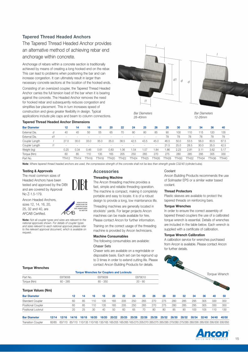
Position the continuation bar with the coupleragainst the end of the first bar.
Rotate the coupler from the continuation bar toengage against the rear of the thread on theopposing bar and lock tight.
2 3
The Bartec Type C System
Screw the locknut followed by the coupler tothe rear of the thread on the continuation bar.
1
4
Rotate the locknut along the continuation bar to abut the coupler.
Hold the rebar in its required orientation and with a wrench tighten the locknut against the coupler.
5
19
d
l
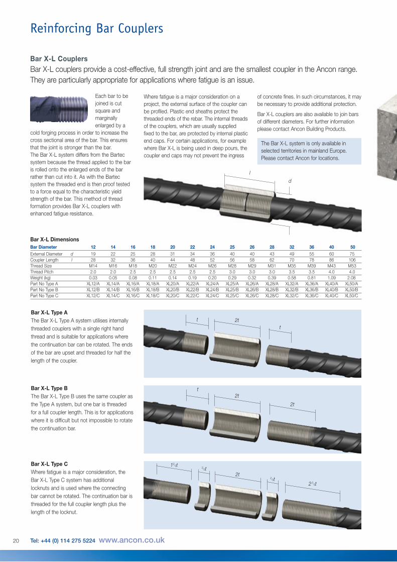
Bar X-L Dimensions
Reinforcing Bar Couplers
Bar X-L Type AThe Bar X-L Type A system utilises internallythreaded couplers with a single right handthread and is suitable for applications wherethe continuation bar can be rotated. The endsof the bar are upset and threaded for half thelength of the coupler.
Bar X-L Type BThe Bar X-L Type B uses the same coupler asthe Type A system, but one bar is threadedfor a full coupler length. This is for applicationswhere it is difficult but not impossible to rotatethe continuation bar.
Bar X-L Type CWhere fatigue is a major consideration, theBar X-L Type C system has additionallocknuts and is used where the connectingbar cannot be rotated. The continuation bar isthreaded for the full coupler length plus thelength of the locknut.
Each bar to bejoined is cutsquare andmarginallyenlarged by a
cold forging process in order to increase thecross sectional area of the bar. This ensuresthat the joint is stronger than the bar.The Bar X-L system differs from the Bartecsystem because the thread applied to the baris rolled onto the enlarged ends of the barrather than cut into it. As with the Bartecsystem the threaded end is then proof testedto a force equal to the characteristic yieldstrength of the bar. This method of threadformation provides Bar X-L couplers withenhanced fatigue resistance.
Bar Diameter 12 14 16 18 20 22 24 25 26 28 32 36 40 50External Diameter d 19 22 25 28 31 34 36 40 40 43 49 55 60 75Coupler Length l 28 32 36 40 44 48 52 56 58 62 70 78 86 106Thread Size M14 M16 M18 M20 M22 M24 M26 M28 M29 M31 M35 M39 M43 M53Thread Pitch 2.0 2.0 2.5 2.5 2.5 2.5 2.5 3.0 3.0 3.0 3.5 3.5 4.0 4.0Weight (kg) 0.03 0.05 0.08 0.11 0.14 0.19 0.20 0.29 0.32 0.39 0.58 0.81 1.09 2.08Part No Type A XL12/A XL14/A XL16/A XL18/A XL20/A XL22/A XL24/A XL25/A XL26/A XL28/A XL32/A XL36/A XL40/A XL50/APart No Type B XL12/B XL14/B XL16/B XL18/B XL20/B XL22/B XL24/B XL25/B XL26/B XL28/B XL32/B XL36/B XL40/B XL50/BPart No Type C XL12/C XL14/C XL16/C XL18/C XL20/C XL22/C XL24/C XL25/C XL26/C XL28/C XL32/C XL36/C XL40/C XL50/C
Where fatigue is a major consideration on aproject, the external surface of the coupler canbe profiled. Plastic end sheaths protect thethreaded ends of the rebar. The internal threadsof the couplers, which are usually suppliedfixed to the bar, are protected by internal plasticend caps. For certain applications, for examplewhere Bar X-L is being used in deep pours, thecoupler end caps may not prevent the ingress
of concrete fines. In such circumstances, it maybe necessary to provide additional protection.
Bar X-L couplers are also available to join barsof different diameters. For further informationplease contact Ancon Building Products.
2ttt
2tt
12/3t
2t2/3t
2 2/3t
2t
2/3t
20 Tel: +44 (0) 114 275 5224 www.ancon.co.uk
Bar X-L CouplersBar X-L couplers provide a cost-effective, full strength joint and are the smallest coupler in the Ancon range.They are particularly appropriate for applications where fatigue is an issue.
The Bar X-L system is only available inselected territories in mainland Europe.Please contact Ancon for locations.

Testing & ApprovalsBar X-L couplers are designed andmanufactured in accordance with BS EN ISO9001 and comply in all respects to BS EN1992-1-1: 2004 (Eurocode 2) and BS 8110when used with reinforcing bars to BS4449.Couplers in bar sizes 36, 43 and 57 have beentested and show compliance with ASME III DIV 2 (ACI 359) and ACI 349.
Two Stage ConstructionIn two stage construction utilising Types B andC couplers, it is essential to form a pocket inthe face of the first stage concrete. This willcreate the space for the coupler to run ontothe thread of the fixed reinforcing bar.
A pocket former is screwed onto the end of thebar and cast flush with the face of the concrete.
Mobile Bar End Preparation FacilityBar X-L threading equipment is generallyestablished in the rebar supplier’s premisesand couplers are usually supplied pre-fixed tothe threaded bar ends.
On large contracts where bar end preparationcan be carried out on site, equipment can be made available for hire. It should be notedthat the hirer will need to provide sufficientpower, air, rebar support tressles and cranehandling facilities.
21

Reinforcing Bar Couplers
Remove the plastic cap from the coupler.Position and rotate the continuation bar in the coupler.
2 3
InstallationThe Bar X-L Type A System
Tighten the joint using a wrench on thecontinuation bar.
Position the continuation bar with the coupleragainst the end of the fixed bar.
Run the coupler from the continuation bar ontothe fixed bar.
2 3
The Bar X-L Type B System
Run the coupler to the end of the thread onthe continuation bar.
1
Tighten the joint using a wrench on thecontinuation bar.
Run the coupler to the end of the thread onthe fixed bar.
1
4
22 Tel: +44 (0) 114 275 5224 www.ancon.co.uk

Run the second locknut followed by thecoupler to the end of the thread on thecontinuation bar.
Position the continuation bar with the coupleragainst the end of the fixed bar.
2 3
The Bar X-L Type C System
Run the locknut onto the fixed bar.
1
Run the locknut along the continuation bar toabut the coupler.
5
Run the coupler from the continuation bar ontothe fixed bar.
4
Tighten the locknuts against each other usinga pair of wrenches.
6
23
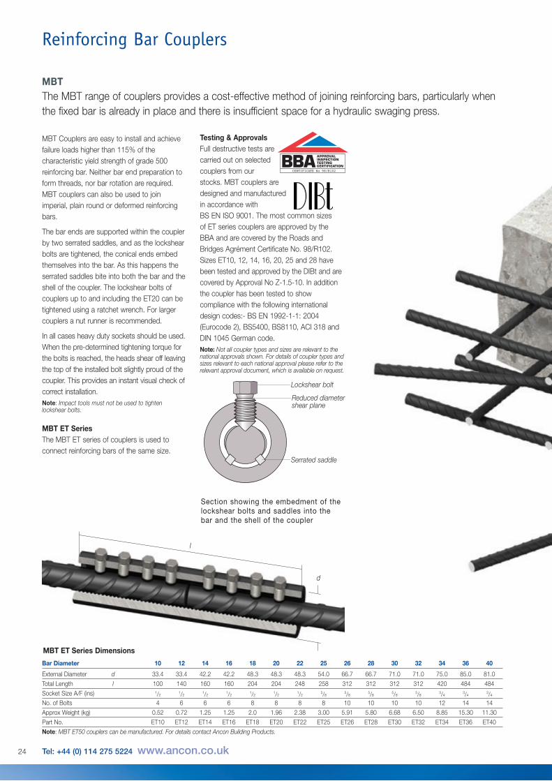
MBT Couplers are easy to install and achievefailure loads higher than 115% of thecharacteristic yield strength of grade 500reinforcing bar. Neither bar end preparation toform threads, nor bar rotation are required.MBT couplers can also be used to joinimperial, plain round or deformed reinforcingbars.
The bar ends are supported within the couplerby two serrated saddles, and as the lockshearbolts are tightened, the conical ends embedthemselves into the bar. As this happens theserrated saddles bite into both the bar and theshell of the coupler. The lockshear bolts ofcouplers up to and including the ET20 can betightened using a ratchet wrench. For largercouplers a nut runner is recommended.
In all cases heavy duty sockets should be used.When the pre-determined tightening torque forthe bolts is reached, the heads shear off leavingthe top of the installed bolt slightly proud of thecoupler. This provides an instant visual check ofcorrect installation.Note: Impact tools must not be used to tightenlockshear bolts.
MBT ET SeriesThe MBT ET series of couplers is used toconnect reinforcing bars of the same size.
Reinforcing Bar Couplers
Bar Diameter 10 12 14 16 18 20 22 25 26 28 30 32 34 36 40
External Diameter d 33.4 33.4 42.2 42.2 48.3 48.3 48.3 54.0 66.7 66.7 71.0 71.0 75.0 85.0 81.0Total Length l 100 140 160 160 204 204 248 258 312 312 312 312 420 484 484Socket Size A/F (ins) 1/2
1/21/2
1/21/2
1/21/2
5/85/8
5/85/8
5/83/4
3/43/4
No. of Bolts 4 6 6 6 8 8 8 8 10 10 10 10 12 14 14Approx Weight (kg) 0.52 0.72 1.25 1.25 2.0 1.96 2.38 3.00 5.91 5.80 6.68 6.50 8.85 15.30 11.30Part No. ET10 ET12 ET14 ET16 ET18 ET20 ET22 ET25 ET26 ET28 ET30 ET32 ET34 ET36 ET40Note: MBT ET50 couplers can be manufactured. For details contact Ancon Building Products.
l
d
24 Tel: +44 (0) 114 275 5224 www.ancon.co.uk
MBT ET Series Dimensions
MBTThe MBT range of couplers provides a cost-effective method of joining reinforcing bars, particularly whenthe fixed bar is already in place and there is insufficient space for a hydraulic swaging press.
Testing & ApprovalsFull destructive tests arecarried out on selectedcouplers from ourstocks. MBT couplers aredesigned and manufacturedin accordance withBS EN ISO 9001. The most common sizesof ET series couplers are approved by theBBA and are covered by the Roads andBridges Agrément Certificate No. 98/R102.Sizes ET10, 12, 14, 16, 20, 25 and 28 havebeen tested and approved by the DIBt and arecovered by Approval No Z-1.5-10. In additionthe coupler has been tested to showcompliance with the following internationaldesign codes:- BS EN 1992-1-1: 2004(Eurocode 2), BS5400, BS8110, ACI 318 andDIN 1045 German code.Note: Not all coupler types and sizes are relevant to thenational approvals shown. For details of coupler types andsizes relevant to each national approval please refer to therelevant approval document, which is available on request.
CERTIFICATE No 98/R102
Section showing the embedment of thelockshear bolts and saddles into thebar and the shell of the coupler
Lockshear bolt
Reduced diametershear plane
Serrated saddle
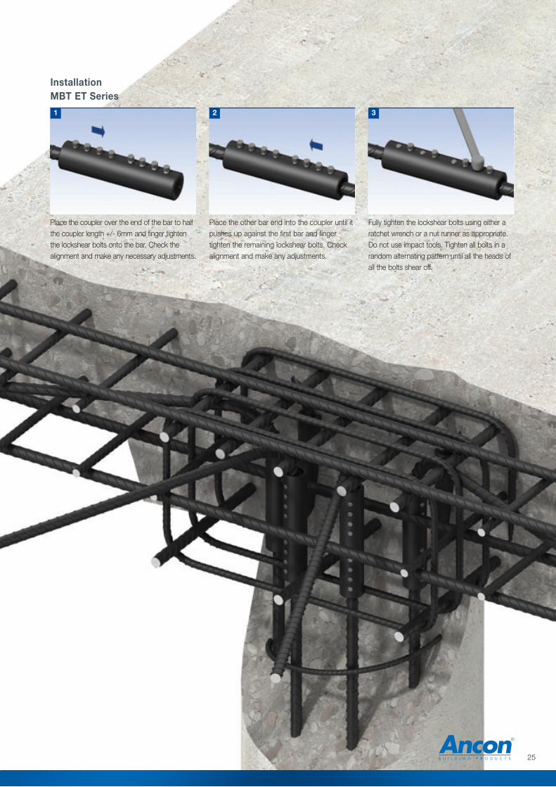
Place the other bar end into the coupler until itpushes up against the first bar and fingertighten the remaining lockshear bolts. Checkalignment and make any adjustments.
Fully tighten the lockshear bolts using either aratchet wrench or a nut runner as appropriate.Do not use impact tools. Tighten all bolts in arandom alternating pattern until all the heads ofall the bolts shear off.
2 3
InstallationMBT ET Series
Place the coupler over the end of the bar to halfthe coupler length +/- 6mm and finger tightenthe lockshear bolts onto the bar. Check thealignment and make any necessary adjustments.
1
25

Reinforcing Bar Couplers
l
a
d
b
d2
MBT Transition Series Dimensions
Bar Diameter 16/12 16/14 20/12 20/16 25/16 25/20 28/20 28/22 28/25 32/20 32/25 32/28 40/32
External Diameter d 42.2 42.2 48.3 48.3 54.0 54.0 66.7 66.7 66.7 71.0 71.0 71.0 81.0External Diameter d2 26.4 42.2 33.4 48.3 42.2 54.0 48.3 41.7 54.0 48.3 54.0 66.7 71.0Total Length l 160 160 150 160 155 180 204 253 258 177 231 286 335Individual Lengths a:b 80:80 80:80 80:70 80:80 75:80 90:90 102:102 129:124 129:129 75:102 102:129 130:156 178:157Socket Size A/F (ins) a:b 1/2:1/2
1/2:1/21/2:1/2
1/2:1/25/8:1/2
5/8:1/25/8:1/2
5/8:1/25/8:5/8
5/8:1/25/8:5/8
5/8:5/83/4:5/8
No. of Bolts a:b 3:3 3:3 3:3 3:3 2:3 3:3 3:4 4:5 4:4 2:4 3:4 4:5 5:5Approx Weight (kg) 1.30 1.25 1.13 1.56 1.51 2.23 2.94 3.61 3.98 2.55 3.70 5.71 7.47
Part No. ET16/12 ET16/14 ET20/12 ET20/16 ET25/16 ET25/20 ET28/20 ET28/22 ET28/25 ET32/20 ET32/25 ET32/28 ET40/32
Place the other bar end into the coupler until itpushes up against the first bar and fingertighten the remaining lockshear bolts. Checkalignment and make any adjustments.
2
InstallationMBT Transition Series
Place the coupler over the end of the bar to theappropriate depth +/- 6mm and finger tightenthe lockshear bolts onto the bar. Check thealignment and make any necessary adjustments.
1
Fully tighten the lockshear bolts using either aratchet wrench or a nut runner as appropriate.Do not use impact tools. Tighten all bolts in arandom alternating pattern until all the headsof all the bolts shear off.
3
Transition couplers have all of the benefits of theET series and are designed to achieve failureloads higher than 115% of the characteristicyield strength of the smaller grade 500reinforcing bar.
They can be installed without any preparation tothe bar ends and without any need to rotatebars.
The coupler can be rotated to allow access tothe bolts for tightening with either a ratchetwrench or a nut runner. In all cases heavy dutysockets should be used. Transition couplersare non-standard and are made to order.Note: Impact tools should not be used to tightenlockshear bolts.
Repair and Remedial WorkFor applications involving replacement ofcorroded or damaged bars, thereplacement bar is cut approximately5mm shorter to allow clearance forinsertion between the sound ends of theoriginal bars. MBT couplers are pushedfully over both ends of the replacementbar and temporarily held in position.
The replacement bar is then correctlypositioned and the couplers moved to apreviously marked position on the existingbars indicating half the length of thecoupler. The lockshear bolts are tightenedto complete the installation.
26 Tel: +44 (0) 114 275 5224 www.ancon.co.uk
MBT Transition SeriesThe MBT Transition series of couplers provides aneffective solution for connecting bars of different diameters.

l
a
a
d
c
d
cl
Bar Diameter 12 16 20 25 32 40
External Diameter d 33.4 42.2 48.3 54.0 71.0 81.0Maximum Length l 250 280 297 357 431 603Female Component Length a 100 115 147 177 214 300Threaded Section c 30 35 38 43 53 53Socket Size A/F (ins) 1/2
1/21/2
5/85/8
3/4
No. of Bolts 6 6 8 8 10 14Nail Plate Diameter x Thickness 75 x 5 75 x 5 75 x 5 100 x 5 100 x 5 127 x 5Approx Weight (kg) 1.34 2.34 2.85 4.42 9.58 16.17Part No. C12 C16 C20 C25 C32 C40
c
MBT Continuity Series 12mm and 16mm Dimensions
MBT Continuity Series 20mm to 40mm Dimensions
27
MBT Continuity SeriesThe MBT Continuity couplerallows reinforcement to beextended at construction jointswithout the need to drill orotherwise substantially defacethe formwork.The female part of the coupler is fixed to theformwork with the aid of a nail plate.
After removal of the formwork, the nail plateprotects the internally threaded end of thecoupler. It is advisable to loosen the nail plate tobreak the bond with the concrete whilst it is still'green'. When the nail plate is removed, themale section can be screwed into the existingsection of the coupler.
The 12mm and 16mm couplers haveadditional locknuts which are used to securethe connection. The two sections of sizes20mm to 40mm couplers are locked togetherby an expanding cone in the male section.
Reinforcing Bar Couplers
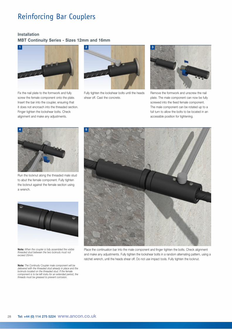
Fix the nail plate to the formwork and fullyscrew the female component onto the plate.Insert the bar into the coupler, ensuring that it does not encroach into the threaded section.Finger tighten the lockshear bolts. Checkalignment and make any adjustments.
Run the locknut along the threaded male studto abut the female component. Fully tighten the locknut against the female section using a wrench.
Note: When the coupler is fully assembled the visiblethreaded stud between the two locknuts must notexceed 20mm.
4
Fully tighten the lockshear bolts until the headsshear off. Cast the concrete.
2
Place the continuation bar into the male component and finger tighten the bolts. Check alignmentand make any adjustments. Fully tighten the lockshear bolts in a random alternating pattern, using aratchet wrench, until the heads shear off. Do not use impact tools. Fully tighten the locknut.
5
InstallationMBT Continuity Series - Sizes 12mm and 16mm
1
Remove the formwork and unscrew the nailplate. The male component can now be fullyscrewed into the fixed female component.The male component can be rotated up to afull turn to allow the bolts to be located in anaccessible position for tightening.
3
Note: The Continuity Coupler male component will bedelivered with the threaded stud already in place and thelocknuts located on the threaded stud. If the femalecomponent is to be left insitu for an extended period, thethreads must be greased to prevent corrosion.
28 Tel: +44 (0) 114 275 5224 www.ancon.co.uk
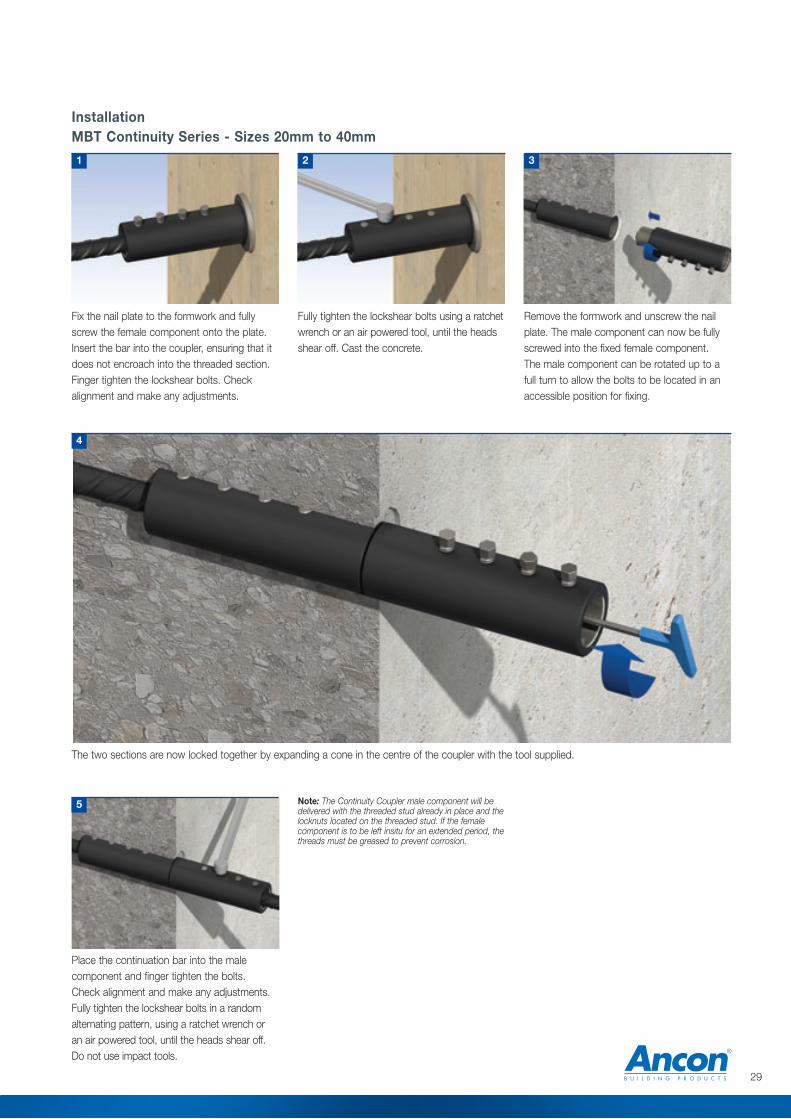
Fix the nail plate to the formwork and fullyscrew the female component onto the plate.Insert the bar into the coupler, ensuring that itdoes not encroach into the threaded section.Finger tighten the lockshear bolts. Checkalignment and make any adjustments.
Fully tighten the lockshear bolts using a ratchetwrench or an air powered tool, until the headsshear off. Cast the concrete.
Remove the formwork and unscrew the nailplate. The male component can now be fullyscrewed into the fixed female component.The male component can be rotated up to afull turn to allow the bolts to be located in anaccessible position for fixing.
2 31
The two sections are now locked together by expanding a cone in the centre of the coupler with the tool supplied.
4
Place the continuation bar into the malecomponent and finger tighten the bolts. Check alignment and make any adjustments.Fully tighten the lockshear bolts in a randomalternating pattern, using a ratchet wrench or an air powered tool, until the heads shear off. Do not use impact tools.
5
InstallationMBT Continuity Series - Sizes 20mm to 40mm
Note: The Continuity Coupler male component will bedelivered with the threaded stud already in place and thelocknuts located on the threaded stud. If the femalecomponent is to be left insitu for an extended period, thethreads must be greased to prevent corrosion.
5
29

Reinforcing Bar Couplers
Bar Diameter 10 12 14 16 18 20 22 25 26 28 30 32 34 36 40
External Diameter d 33.4 33.4 42.2 42.2 48.3 48.3 48.3 54.0 66.7 66.7 71.0 71.0 75.0 85.0 81.0
Coupler Length l 55 75 82 82 104 104 126 129 156 156 156 156 215 247 247
Total Length lo 65 85 92 92 114 114 136 139 168 168 171 171 230 262 262
Plate Thickness t 10 10 10 10 10 10 10 10 12 12 15 15 15 15 15
Plate w x h p 70 70 70 80 90 90 90 100 110 110 130 130 130 150 150
Socket Size A/F (ins) 1/21/2
1/21/2
1/21/2
1/25/8
5/85/8
5/85/8
3/43/4
3/4
No of Bolts 2 3 3 3 4 4 5 4 5 5 5 5 6 7 7
Approx Weight (kg) 0.64 0.74 1.01 1.07 1.58 1.58 1.72 2.29 3.81 4.14 5.08 4.72 5.17 9.13 8.30
Part No. ETHA10 ETHA12 ETHA14 ETHA16 ETHA18 ETHA20 ETHA22 ETHA25 ETHA26 ETHA28 ETHA30 ETHA32 ETHA34 ETHA36 ETHA40
Note: Minimum compressive strength of concrete 25N/mm2.
l
t
p
d
lo
MBT Headed AnchorsMBT Headed Anchors are designed to provide dead end embedmentfor bars in concrete. This helps to reduce congestion and simplify theplacement of rebars by removing the need for hooked ends.
The anchor comprises half an MBT coupler with a plate welded to one end which carries the fulltension load of the bar when it is bearing against the concrete. The MBT Headed Anchor also hasthe added advantage of requiring no special bar end preparation.
30 Tel: +44 (0) 114 275 5224 www.ancon.co.uk

Other Ancon ProductsReinforcement Continuity SystemsReinforcement Continuity Systems are anincreasingly popular means of maintainingcontinuity of reinforcement at constructionjoints in concrete. Ancon Eazistrip is approvedby UK CARES and consists of pre-bent barshoused within a galvanised steel casing. Onceinstalled, the protective cover is removed andthe bars are straightened. Ancon Starter Barsare supplied fixed to an Ancon coupler. Oncecast in concrete, the coupler’s end cap isremoved and a threaded continuation bar isinstalled with a calibrated torque wrench tocomplete the connection.
Shear Load ConnectorsAncon DSD and ESD Shear Load Connectorsare used to transfer shear across expansionand contraction joints in concrete. They aremore effective at transferring load and allowingmovement to take place than standard dowels.The range features rectangular box sectionsleeves to allow lateral movement in addition tolongitudinal movement. A range of LockableDowels is available for temporary movementjoints in post-tensioned concrete.
Channel and Bolt FixingsAncon offers a wide range of channels andbolts in order to fix stainless steel masonrysupport, restraints and windposts to structuralframes. Cast-in channels and expansion boltsare used for fixing to the edges of concretefloors and beams.
Punching Shear ReinforcementAncon Shearfix is used within a slab to provideadditional reinforcement from punching sheararound columns. The system is approved byUK CARES and consists of double-headedsteel studs welded to flat rails. Shearfix isdesigned to suit the load conditions and slabdepth at each column using free calculationsoftware from Ancon.
Insulated Balcony ConnectionsAncon Isolan connectors join external concretebalconies to internal concrete floor slabs.Used to minimise cold bridging, they providecontinuity to the thermal insulation. Standardsystems, comprising rigid CFC-free polystyreneinsulation and duplex stainless steel shearreinforcement, suit most depths of cantileveredand simply supported balconies. Solutions forsteel framed buildings and steel balconies arealso available.
Electric WrenchTo facilitate the installation of MBT couplersAncon Electric Wrenches are available forpurchase or hire. The smooth continuousaction of the wrench prevents the earlyshearing of the lockshear bolts and damage tothreads. The wrench is supplied with speciallyhardened heavy duty sockets. For detailsplease contact Ancon.
Note: Impact tools should not be used to tightenlockshear bolts. In all cases heavy duty socketsshould be used.
31

ISO 9001: 2008FM 12226
ISO 14001: 2004EMS 505377
OHSAS 18001: 2007OHS 548992
© Ancon Building Products 2012
The construction applications and details provided in this literature are indicative only. In every case, project workingdetails should be entrusted to appropriately qualified and experienced persons.
Whilst every care has been exercised in the preparation of this document to ensure that any advice, recommendations orinformation is accurate, no liability or responsibility of any kind is accepted in respect of Ancon Building Products.
With a policy of continuous product development Ancon Building Products reserves the right to modify product designand specification without due notice.
These products are available from:
Masonry Support Systems
Lintels
Masonry Reinforcement
Windposts and Parapet Posts
Wall Ties and Restraint Fixings
Channel and Bolt Fixings
Tension and Compression Systems
Insulated Balcony Connectors
Shear Load Connectors
Punching Shear Reinforcement
Reinforcing Bar Couplers
Reinforcement Continuity Systems
Stainless Steel Fabrications
Flooring and Formed Sections
Refractory Fixings
Ancon Building Products114 Kurrajong AvenueMount DruittSydneyNSW 2770AustraliaTel: +61 (0) 2 8808 1111Fax: +61 (0) 2 9675 3390Email: [email protected]: www.ancon.com.au
Ancon (Schweiz) AGGewerbezone Widalmi 103216 Ried bei KerzersSwitzerlandTel: +41 (0) 31 750 3030Fax: +41 (0) 31 750 3033 Email: [email protected]: www.ancon.ch
Ancon Building Products GesmbHGerspergasse 9/3 Top 1A-1210 ViennaAustriaTel: +43 (0) 1 259 58 62-0Fax: +43 (0) 1 259 58 62-40Email: [email protected]: www.ancon.at
Ancon GmbHBartholomäusstrasse 2690489 NurembergGermanyTel: +49 (0) 911 955 1234 0Fax: +49 (0) 911 955 1234 9Email: [email protected]: www.anconbp.de
Ancon Building ProductsPresident Way, President ParkSheffield S4 7URUnited KingdomTel: +44 (0) 114 275 5224Fax: +44 (0) 114 276 8543Email: [email protected]: www.ancon.co.ukFollow on Twitter: @AnconUK
Ancon (Middle East) FZEPO Box 17225Jebel AliDubaiUnited Arab EmiratesTel: +971 (0) 4 883 4346Fax: +971 (0) 4 883 4347Email: [email protected]: www.ancon.ae