Embed Size (px)
Citation preview
Reinforcement of Solid-Melt Interfaces for SemicrystallinePolymers in a Sequential Two-Staged InjectionMolding Process
GENJIE JIANG, HONG WU, BOWEN YAN, SHAOYUN GUO, JIAN HUANG
The State Key Laboratory of Polymer Materials Engineering, Polymer Research Institute of Sichuan University,Chengdu 610065, China
Received 3 February 2009; revised 18 March 2009; accepted 29 March 2009DOI: 10.1002/polb.21719Published online in Wiley InterScience (www.interscience.wiley.com).
ABSTRACT: The solid-melt interfaces between polyethylene (PE) and polyamide 6(PA6) reinforced by in situ reactive compatibilization in a sequential two-staged injec-tion molding process has been studied in this work. The effects of the maleic anhy-dride grafted PE content and processing parameters, such as injection pressure,injection speed, melt temperature, and mold temperature, on the interfacial adhesionwere investigated experimentally. The results of the interfacial adhesion character-ized by lap shear measurement showed that the interfacial temperature and heattransfer between PE and PA6 interfaces play a very significant role in the bondingprocess. The fracture surfaces of the specimens prepared at different calculated inter-facial temperature were investigated by scanning electron microscopy (SEM) and dif-ferential scanning calorimetry (DSC), which suggested that the fracture failurechanges from adhesive to cohesive failure with increasing interfacial temperature.The contribution of crystalline parts of the in situ formed copolymers to the enhance-ment in interfacial adhesion also was determined by DSC analysis. VVC 2009 Wiley
Periodicals, Inc. J Polym Sci Part B: Polym Phys 47: 1112–1124, 2009
Keywords: adhesion; injection molding; interfaces; polyamide 6; polyethylene;reinforcement; sequential two-staged injection molding process; solid-melt interfaces
INTRODUCTION
Injection molding is one of most used processingoperations for thermalplastics polymers due to itshigh production efficiency and dimensional diver-sity and precision. Recently, sequential injectionmolding, also called over-injection molding (OIM),has gained considerable importance in the field ofpolymer processing,1–5 such as polymer weldingor bonding and complex plastic parts assembly.Compared with the conventional injection mold-
ing, sequential injection molding includes multi-stage operation: the first part of desired figure ismolded by one-stage injection, and then the meltfor the second part is subsequently injected overthe surface of the first part molded in the previousprocess. This process can be repeated by manytimes until all the parts constitute the desired fig-ure. It is feasible to develop this processing tech-nique to make versatile and complex products,and to accomplish the welding process of polymerparts simultaneously during injection molding.But one obstacle that limits the application of thistechnique is the imperfect healing of weldline atthe incipient solid-melt interface formed duringtwo-staged injection molding. The low welding
Journal of Polymer Science: Part B: Polymer Physics, Vol. 47, 1112–1124 (2009)VVC 2009 Wiley Periodicals, Inc.
Correspondence to: H. Wu (E-mail: [email protected]) orS. Guo (E-mail: [email protected])
1112
strength at solid-melt will induce the generationof cracks or even interfacial fractures at the weld-ing interfaces when the molded components areused in environmental stress field, especially forautomobile accessories produced through thistechnique. So it is essential to understand howthe strength at the incipient solid-melt interfacedepends on the processing parameters and theinterfacial structure, what is the difference ofbonding process for solid-melt interface in com-parison with melt-melt interface, as well as howto control processing conditions to improvethe strength at the interface formed during OIMprocessing.
Huang and Chen6 established a theoreticalbonding strength model to predict the relation-ship between the degree of bonding at solid-meltinterface and average extent of reaching an effec-tive penetration depth on the base of interfacialdiffusion and entanglements theory. It showedthat the efficiency of bonding at solid-melt inter-face is only as high as 0.5872 times of that atmelt-melt interface. They asserted that a steeptemperature gradient is built across the solid-melt interface during bonding process in a se-quential injection molding, which will lead to anonuniform interdiffusion and entanglements ofpolymer chains across the interface. In addition,when solid and melt interfaces are brought intocontact, the heat transfer from the melt to thesolid surface quickly will make the interdiffusiontime shorter compared with melt-melt interface,therefore, result in insufficient extent of chainentanglements for solid-melt interface. The valid-ity of the above theoretical model was verified inover-injection molded polystyrene system pre-pared under various processing conditions. How-ever, this theoretical model can only be used inthe amorphous polymer system, since the bondingstrength of crystalline polymer interface isaffected by crystalline structure at the interfacebesides the interdiffusion and entanglement.Carella et al.7 discussed the effect of the processparameters in OIM process on the bondingstrength of polyolefin thermoplastic elastomers(TPO) materials. Through calculating the temper-ature and pressure at the solid-melt polymerinterface prepared at different conditions, theysuggested that poor heat transfer rate across thesolid and melt interface results in poor bonding atthe interface in the whole bonding process. Melttemperature can be reduced with appropriatecombinations of mold temperature and packing
pressure. The optimal processing conditions wereproposed for experimental system. Qiu et al.8
investigated the effect of interfacial morphologyon the bonding strength of over-injection moldedpolyamide 6 (PA6) systems. It was observed thatthe transcrystals grow along the perpendiculardirection of the solid-melt interface under certaintemperature and shear gradient, which is benefi-cial to improve the bonding strength because thenuclei of the transcrystals are formed at the skinlayer of the first injection molded part. The inter-facial bonding strength can attain to the shearstrength of base material.
However, most A/B polymer pairs are themody-namically immiscible. Therefore, the interfacialadhesion between them is very weak due to thelack of chain entanglements at the interface. Theprevalent means of diminishing incompatibility ata polymer/polymer interface is by the addition ofa third component (often a diblock or randomcopolymers) or in situ reactive compatibilization.Due to the compatibilizing efficiency andeasy operation, the later one has obtained thegreat interest in industry. A lot of theoretical andexperimental studies9–13 have been concentratedon the fundamental understanding of theenhancement in interfacial adhesion resultingfrom reactive compatibilization. Semicrystallinepolymer blends, such as PP/PA6 and PE/PA6,have been extensively used as structural mate-rial, packing material and gasoline tank. In gen-eral, the interfacial adhesion between them isimproved by the incorporation of a small amountof maleic anhydride functionalized polymer, whichcan react with NH2 group of PA6 to form copoly-mers as in situ compatibilizers. On the basis of amodel sandwich polymer interface, which excludethe complex effect of shear and elongational flowson the reactive compatibilization, the effect of theformation of in situ copolymers on the adhesionpromotion at PP/PA614–16 and PE/PA617,18 inter-face have been investigated profoundly. Mansonand coworkers19 studied the bonding of maleic an-hydride grafted PP and PA6 interface. The experi-mental results showed that the interfacial frac-ture toughness (Gc) increases significantly at twoobvious transitions corresponding to the melttemperature of each component. The enhance-ment in interfacial adhesion is also influenced bythe bonding time. Some other works20,21 haveshowed that Gc increases with the bonding timeand then reaches a plateau, indicating that theinterfacial reaction has attained to a level of satu-ration. Cho and Li20 investigated the effect of
REINFORCEMENT OF SOLID-MELT INTERFACES 1113
Journal of Polymer Science: Part B: Polymer PhysicsDOI 10.1002/polb
maleic anhydride grafted PP (mPP) content onthe interfacial fracture toughness of amorphousPA6/PP at the same bonding temperature, andfound that incorporation of 3 wt % mPP in PP ma-trix is enough for effective interfacial reinforce-ment. The miscibility between the functionalizedpolymer and the matrix also influences theenhancement in interfacial adhesion via in situreactive compatibilization. Laurens et al.22 syn-thesized a series of succinic anhydride functional-ized PP (PPf) with different molecular architec-tures (isotatic-PP, isotatic-PP with 5 wt % PE,syndiotactic-PP, metallocene-PP) and discussedthe role of the architecture of PP block of thein situ formed copolymers on the interfacial frac-ture toughness enhancement for isotactic-PP/PA6.When the PPf is isotatic-PP, Gc of i-PP/PA6 inter-face increases rapidly and then reaches satura-tion value with annealing time due to fully com-patibility with the matrix. Several interestingresults were obtained, When the PPf is PE-PPf,which is only partially compatible with the ma-trix, the extent of the increases of Gc becomes lessobvious and a plateau is not always observed.Additionally, the molecular weight of PPf alsoinfluences Gc, which is shown that the maximumGc is larger for the high molecular weight PPf.They suggested that long copolymer chains aremore efficient than short copolymer ones to rein-force the interface, which is attributed that longcopolymer chains can link several lamellae in thevicinity of the interface due to the epitaxial orien-tation at the interface. Boucher et al.15 arguedthat the crystalline microstructure and macro-structure near the interface should affect themeasured value of Gc on the basis of the experi-mental evidences in the case of PP-PA6 interfacereactive compatibilized at a reaction temperatureabove 220 �C. They found some b-crystalline formof PP appears at the interface, which has a strongreinforcing effect on the adhesion between PP andPA6. Later some other work20,23 was also concen-trated on elucidating the links the interfacial ad-hesion and the crystalline structures in the imme-diate vicinity of the interface. It can be concludedthat the reinforcement of immiscible semicrystal-line polymer interface depends on the processingconditions and the in situ formed copolymer archi-tecture, as well as the morphological structure atthe interface.
OIM has showed great potential application inpolymer molding. However, to our best knowl-edge, the articles which concentrated on theinvestigation of the adhesion between asymmetric
polymer pairs in OIM are hardly reported. Untilvery recently, Arzondo et al.24 compared the bond-ing strength of an ethylene-octene random copoly-mer (EOC) and a low density polyethylene (LDPE)injection molded over the same core - PP. It wasobserved that the interfacial bonding strengthdepends on not only the processing conditions, butalso the Flory-Huggins interaction parameterbetween the interfaces. The bonding strength ofEOC-PP interface is higher than that of LDPE-PPinterface due to better compatibility between EOCand PP. In this work, we will investigate the inter-facial adhesion between semicrystalline polymersof PE and PA6 in OIM process. A certain amountof anhydride functionalized PE (PE-g-MAH) isincorporated into PE, the anhydride group of PE-g-MAH can react with the amine end-group of PA6and form in situ copolymers containing imideslinkage at the PE/PA6 interface, which can resultin the enhancement of interfacial adhesion. Wefocused on how the interfacial adhesion dependson processing conditions and the interfacial frac-ture mechanisms. A simple model for reactivecompatibilization at the solid-melt semicrystallinepolymer interface was presented.
EXPERIMENTAL
Materials
A commercial high density polyethylene (HDPE)(6055AG) with Mn ¼ 6.5 � 104 and a polydisper-sity index PDI ¼ 5.5 was supplied by LanZhou Pe-trochemical Co, SINOPEC, China. The maleic an-hydride grafted HDPE (HDPE-g-MAH) with ma-leic anhydride content of 0.1 wt % and Mn ¼ 5.1 �104 was obtained from Ningbo NengzhiguangNew Materials Technology Co, Polyamide 6 (PA6)with melt index of 6 g/10 min (230 �C/2.16 Kg)was purchased from Xinhui Meida-DMS NylonChips CO, Guangdong, China.
Preparation of Specimens
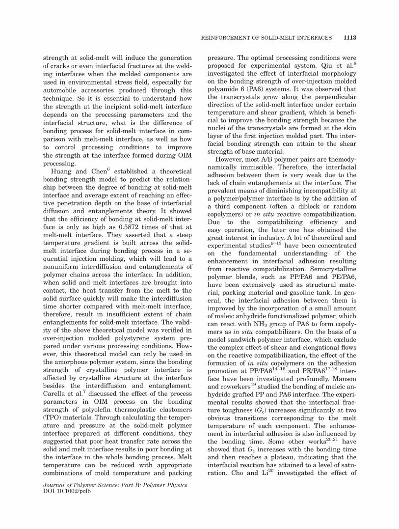
The specimens were prepared by a common injec-tion molding machine and a special mold designedby our laboratory. The schematic of the mold wasgiven in Figure 1(a). The injection moldingmachine used is FERROMATIK MILACRON K-TEC40E manufactured by Germany, which hasthe main features are: screw diameter: 25 mm,maximum injection pressure: 2254 bar, maximuminjection weight: 41.7 g, maximum injection speed:68 cc/s, and maximum clamping force: 40 kN.
1114 JIANG ET AL.
Journal of Polymer Science: Part B: Polymer PhysicsDOI 10.1002/polb
Before two-staged injection molding process,the main steps for preparing specimens includedthe following experimental procedures. Firstly,the HDPE, HDPE-g-MAH, and PA6 were dried ina vacuum oven at a temperature of 80 �C for 24 h.Then the mixtures of dried HDPE and differentweight percent of HDPE-g-MAH were put into acorotating twin-screw extruder (diameter of screw¼ 20, length/diameter ratio ¼ 40/1) for melt blend-ing with a screw speed of 100 rpm and a barreltemperature profile of 160/200/200/190 �C fromhopper to die. The resulted pellets were denotedas HDPE*.
For the two-staged injection molding process,the following experimental nprocedures werefollowed:
1. HDPE* was injected into the first moldcavity [150 � 10 � 4 mm3, shown in Fig.1(a)], and the first injection molded partswere designated as P1.
2. After the first injection, the mold wasopen, P1 was transferred into the secondcavity of the mold (150 mm � 20 mm � 4mm) quickly.
3. Closed the mold for equilibrating the tem-perature at least 5 min.
4. The melt of the second injection moldedparts (P2) were injected over P1.
5. Finally, the mold was opened to pull outthe specimens after a certain cooling time.
Simply, the injection molding conditions for allP1 were same and listed in Table 1.
Measurement of Interfacial Adhesion Strength
Interfacial adhesion strength of the specimenswas characterized by lap shear test. All the speci-mens were cut in a lap shear joint geometry[depicted in Fig. 1(b)]. Stress–strain behaviorswere measured with an Instron 5567 machine(Canton, MA) operating in tension mode at 23 �C.A crosshead speed of 10 mm/min was used in thetest. The shear strength was calculated as themaximal load divided by lap area of shear plane.To minimize error, 10 replicates were tested foreach set of processing conditions.
Observation of Fracture Surfaces
The fracture surfaces of the samples after lapshear measurement were coated with gold andthen observed using a Hitachi S3400 þ EDY scan-ning electron microscope (SEM, Japan) at anaccelerating voltage of 20 kV.
DSC Analysis
Melt and crystalline behaviors of the sampleswere measured by a TA-Q20 (USA) thermal sys-tem purged with nitrogen. To analyze the thermalbehaviors of the interface between P1 and P2 pre-pared by different injection conditions, the injec-tion molded samples were cleaved by a blade, andthen the surface of the cleaved interface with athickness of 25 lm was cut by an ultra-thin micro-tome carefully. The resulting films were used forDSC analysis. The program for DSC measure-ment was run from 25 �C to 250 �C, which is thefirst heating scan. When the sample was equili-brated at 250 �C for 5 min to erase previous ther-mal and stresses history, it was cooled to 25 �C,and then heated again to 250 �C for second heat-ing scan, all at the rate of 10 �C/min, and theendothermic and exothermic curves were all
Table 1. Injection Molding Conditions for the FirstPart (P1)
HDPE *as P1
PA6as P1
Injection melttemperature (�C)
200 240
Mold temperature (�C) 40 40Injection speed(mm/s)
40 40
Injection pressure (MPa) 60 60Cooling time (s) 10 10
Figure 1. Schematic of mold used for OIM (a) andsamples for lap shear measurement (b).
REINFORCEMENT OF SOLID-MELT INTERFACES 1115
Journal of Polymer Science: Part B: Polymer PhysicsDOI 10.1002/polb
recorded and normalized to the unit weight of thesample for analyzing.
RESULTS AND DISCUSSION
Firstly, the effect of processing conditions on theinterfacial adhesion between HDPE* and PA6was investigated. HDPE* was injected as P1 andPA6 was overinjected on that.
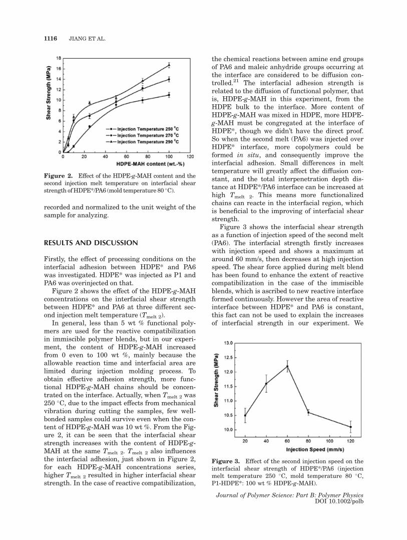
Figure 2 shows the effect of the HDPE-g-MAHconcentrations on the interfacial shear strengthbetween HDPE* and PA6 at three different sec-ond injection melt temperature (Tmelt 2).
In general, less than 5 wt % functional poly-mers are used for the reactive compatibilizationin immiscible polymer blends, but in our experi-ment, the content of HDPE-g-MAH increasedfrom 0 even to 100 wt %, mainly because theallowable reaction time and interfacial area arelimited during injection molding process. Toobtain effective adhesion strength, more func-tional HDPE-g-MAH chains should be concen-trated on the interface. Actually, when Tmelt 2 was250 �C, due to the impact effects from mechanicalvibration during cutting the samples, few well-bonded samples could survive even when the con-tent of HDPE-g-MAH was 10 wt %. From the Fig-ure 2, it can be seen that the interfacial shearstrength increases with the content of HDPE-g-MAH at the same Tmelt 2. Tmelt 2 also influencesthe interfacial adhesion, just shown in Figure 2,for each HDPE-g-MAH concentrations series,higher Tmelt 2 resulted in higher interfacial shearstrength. In the case of reactive compatibilization,
the chemical reactions between amine end groupsof PA6 and maleic anhydride groups occurring atthe interface are considered to be diffusion con-trolled.21 The interfacial adhesion strength isrelated to the diffusion of functional polymer, thatis, HDPE-g-MAH in this experiment, from theHDPE bulk to the interface. More content ofHDPE-g-MAH was mixed in HDPE, more HDPE-g-MAH must be congregated at the interface ofHDPE*, though we didn’t have the direct proof.So when the second melt (PA6) was injected overHDPE* interface, more copolymers could beformed in situ, and consequently improve theinterfacial adhesion. Small differences in melttemperature will greatly affect the diffusion con-stant, and the total interpenetration depth dis-tance at HDPE*/PA6 interface can be increased athigh Tmelt 2. This means more functionalizedchains can reacte in the interfacial region, whichis beneficial to the improving of interfacial shearstrength.
Figure 3 shows the interfacial shear strengthas a function of injection speed of the second melt(PA6). The interfacial strength firstly increaseswith injection speed and shows a maximum ataround 60 mm/s, then decreases at high injectionspeed. The shear force applied during melt blendhas been found to enhance the extent of reactivecompatibilization in the case of the immiscibleblends, which is ascribed to new reactive interfaceformed continuously. However the area of reactiveinterface between HDPE* and PA6 is constant,this fact can not be used to explain the increasesof interfacial strength in our experiment. We
Figure 2. Effect of the HDPE-g-MAH content and thesecond injection melt temperature on interfacial shearstrength ofHDPE*/PA6 (mold temperature 80 �C).
Figure 3. Effect of the second injection speed on theinterfacial shear strength of HDPE*/PA6 (injectionmelt temperature 250 �C, mold temperature 80 �C,P1-HDPE*: 100 wt % HDPE-g-MAH).
1116 JIANG ET AL.
Journal of Polymer Science: Part B: Polymer PhysicsDOI 10.1002/polb
considered intimate contact and fluctuate at inter-face are the reason that cause the interfacialstrength increase with the second injection speedfirstly.
As the injection speed increased further, theorientation of PA6 molecular chains at the inter-face were enhanced significantly due to sheareffect, which would make against the diffusion ofPA6 into HDPE*. Moreover, the functional groupsof PA6 are located at the end of the chains, Withenhancing the degree of chain orientation, the re-active odds between the functional groups of ori-ented PA6 and MAH decreased, then the amountof the in situ formed copolymers at the interfacediminished, therefore, interfacial strengthdecreased when the injection speed increasesfrom 60 to 120 mm/s.
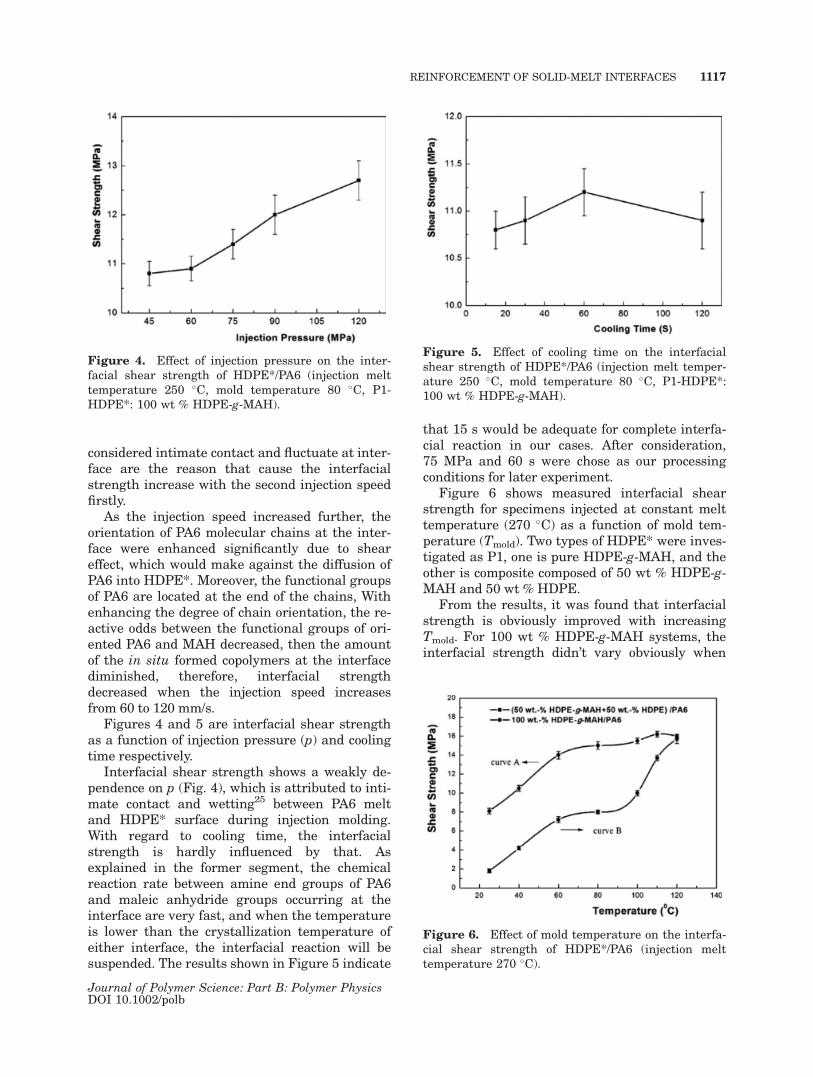
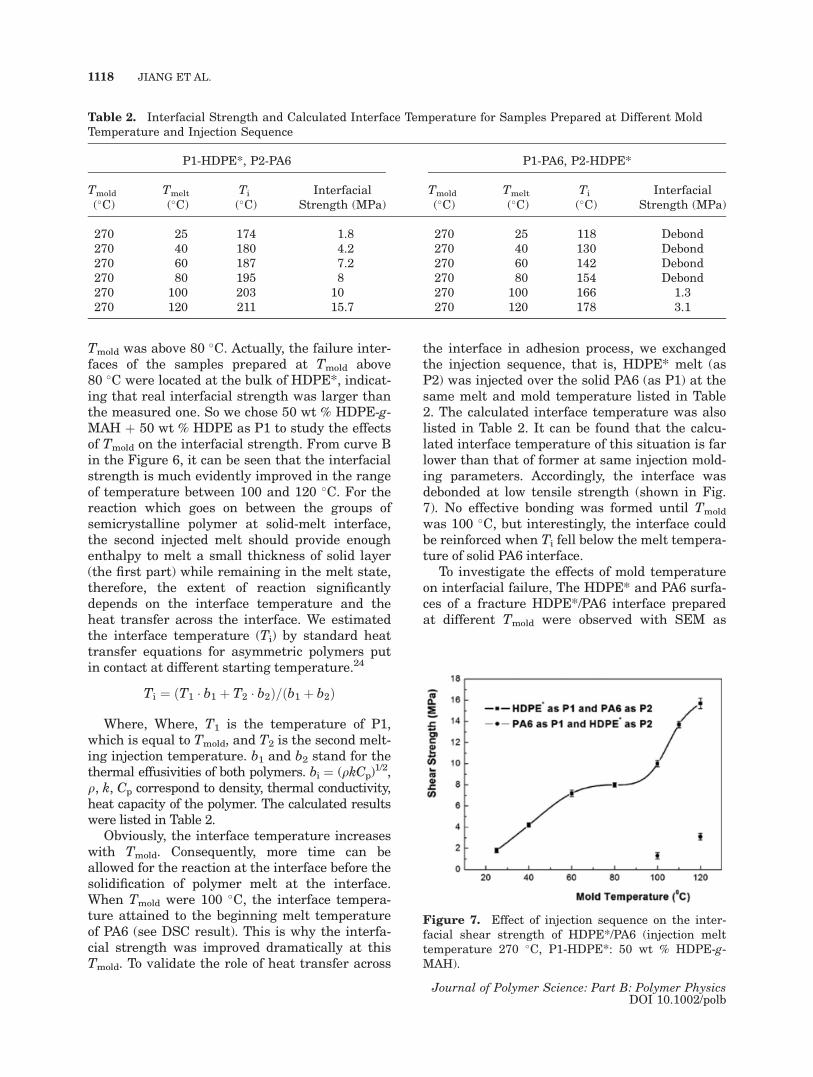
Figures 4 and 5 are interfacial shear strengthas a function of injection pressure (p) and coolingtime respectively.
Interfacial shear strength shows a weakly de-pendence on p (Fig. 4), which is attributed to inti-mate contact and wetting25 between PA6 meltand HDPE* surface during injection molding.With regard to cooling time, the interfacialstrength is hardly influenced by that. Asexplained in the former segment, the chemicalreaction rate between amine end groups of PA6and maleic anhydride groups occurring at theinterface are very fast, and when the temperatureis lower than the crystallization temperature ofeither interface, the interfacial reaction will besuspended. The results shown in Figure 5 indicate
that 15 s would be adequate for complete interfa-cial reaction in our cases. After consideration,75 MPa and 60 s were chose as our processingconditions for later experiment.
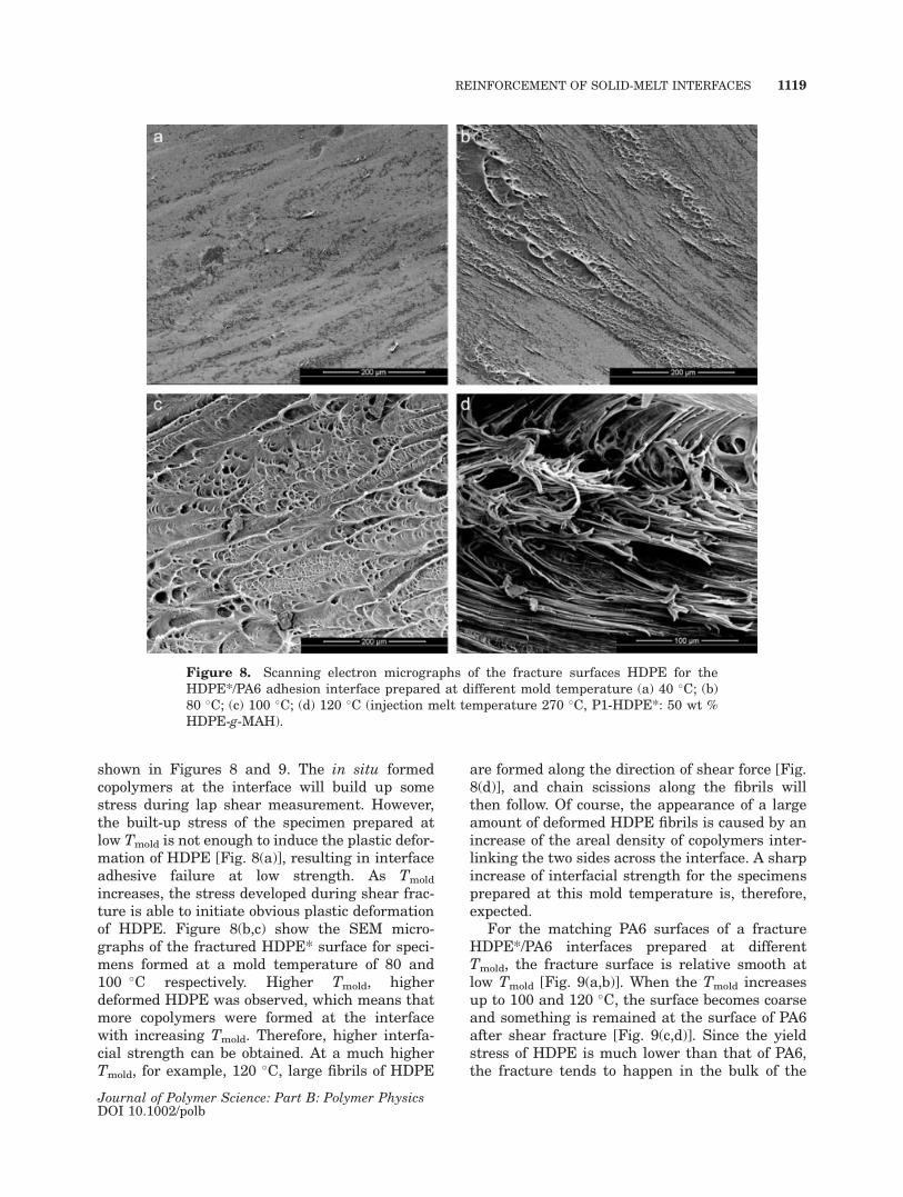
Figure 6 shows measured interfacial shearstrength for specimens injected at constant melttemperature (270 �C) as a function of mold tem-perature (Tmold). Two types of HDPE* were inves-tigated as P1, one is pure HDPE-g-MAH, and theother is composite composed of 50 wt % HDPE-g-MAH and 50 wt % HDPE.
From the results, it was found that interfacialstrength is obviously improved with increasingTmold. For 100 wt % HDPE-g-MAH systems, theinterfacial strength didn’t vary obviously when
Figure 4. Effect of injection pressure on the inter-facial shear strength of HDPE*/PA6 (injection melttemperature 250 �C, mold temperature 80 �C, P1-HDPE*: 100 wt % HDPE-g-MAH).
Figure 5. Effect of cooling time on the interfacialshear strength of HDPE*/PA6 (injection melt temper-ature 250 �C, mold temperature 80 �C, P1-HDPE*:100 wt % HDPE-g-MAH).
Figure 6. Effect of mold temperature on the interfa-cial shear strength of HDPE*/PA6 (injection melttemperature 270 �C).
REINFORCEMENT OF SOLID-MELT INTERFACES 1117
Journal of Polymer Science: Part B: Polymer PhysicsDOI 10.1002/polb
Tmold was above 80 �C. Actually, the failure inter-faces of the samples prepared at Tmold above80 �C were located at the bulk of HDPE*, indicat-ing that real interfacial strength was larger thanthe measured one. So we chose 50 wt % HDPE-g-MAH þ 50 wt % HDPE as P1 to study the effectsof Tmold on the interfacial strength. From curve Bin the Figure 6, it can be seen that the interfacialstrength is much evidently improved in the rangeof temperature between 100 and 120 �C. For thereaction which goes on between the groups ofsemicrystalline polymer at solid-melt interface,the second injected melt should provide enoughenthalpy to melt a small thickness of solid layer(the first part) while remaining in the melt state,therefore, the extent of reaction significantlydepends on the interface temperature and theheat transfer across the interface. We estimatedthe interface temperature (Ti) by standard heattransfer equations for asymmetric polymers putin contact at different starting temperature.24
Ti ¼ ðT1 � b1 þ T2 � b2Þ=ðb1 þ b2Þ
Where, Where, T1 is the temperature of P1,which is equal to Tmold, and T2 is the second melt-ing injection temperature. b1 and b2 stand for thethermal effusivities of both polymers. bi ¼ (qkCp)
1/2,q, k, Cp correspond to density, thermal conductivity,heat capacity of the polymer. The calculated resultswere listed in Table 2.
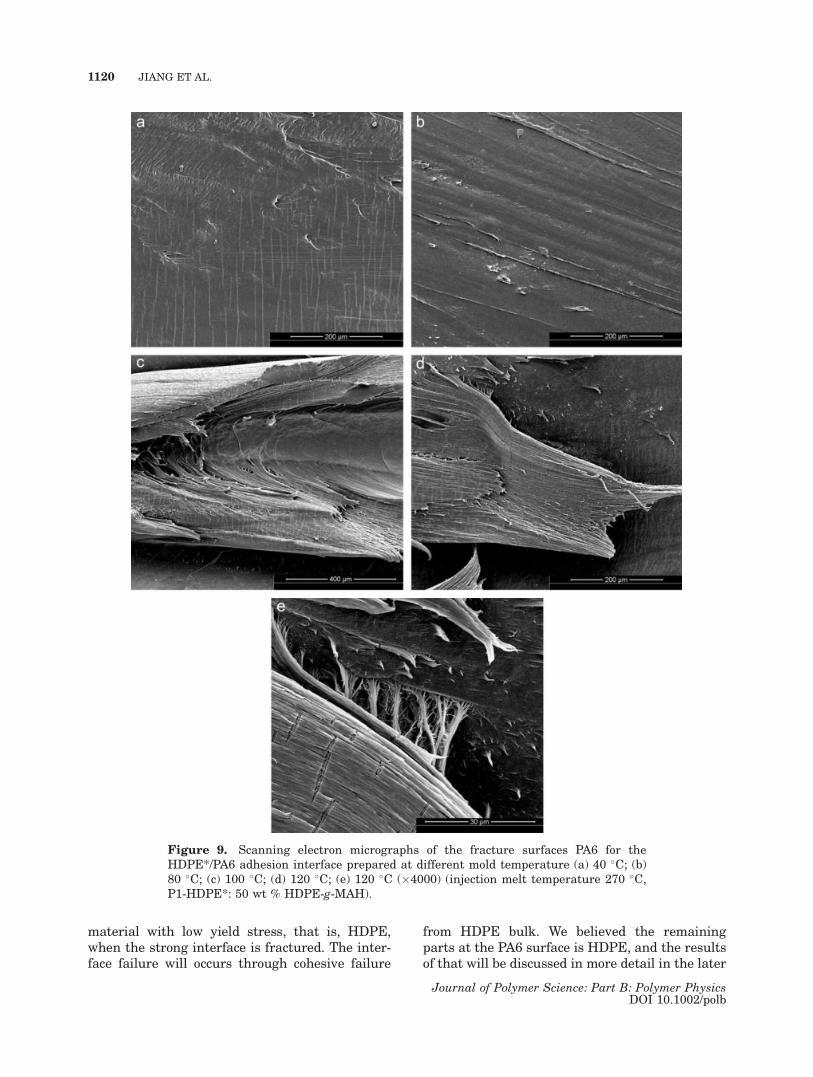
Obviously, the interface temperature increaseswith Tmold. Consequently, more time can beallowed for the reaction at the interface before thesolidification of polymer melt at the interface.When Tmold were 100 �C, the interface tempera-ture attained to the beginning melt temperatureof PA6 (see DSC result). This is why the interfa-cial strength was improved dramatically at thisTmold. To validate the role of heat transfer across
the interface in adhesion process, we exchangedthe injection sequence, that is, HDPE* melt (asP2) was injected over the solid PA6 (as P1) at thesame melt and mold temperature listed in Table2. The calculated interface temperature was alsolisted in Table 2. It can be found that the calcu-lated interface temperature of this situation is farlower than that of former at same injection mold-ing parameters. Accordingly, the interface wasdebonded at low tensile strength (shown in Fig.7). No effective bonding was formed until Tmold
was 100 �C, but interestingly, the interface couldbe reinforced when Ti fell below the melt tempera-ture of solid PA6 interface.
To investigate the effects of mold temperatureon interfacial failure, The HDPE* and PA6 surfa-ces of a fracture HDPE*/PA6 interface preparedat different Tmold were observed with SEM as
Table 2. Interfacial Strength and Calculated Interface Temperature for Samples Prepared at Different MoldTemperature and Injection Sequence
P1-HDPE*, P2-PA6 P1-PA6, P2-HDPE*
Tmold
(�C)Tmelt
(�C)Ti
(�C)Interfacial
Strength (MPa)Tmold
(�C)Tmelt
(�C)Ti
(�C)Interfacial
Strength (MPa)
270 25 174 1.8 270 25 118 Debond270 40 180 4.2 270 40 130 Debond270 60 187 7.2 270 60 142 Debond270 80 195 8 270 80 154 Debond270 100 203 10 270 100 166 1.3270 120 211 15.7 270 120 178 3.1
Figure 7. Effect of injection sequence on the inter-facial shear strength of HDPE*/PA6 (injection melttemperature 270 �C, P1-HDPE*: 50 wt % HDPE-g-MAH).
1118 JIANG ET AL.
Journal of Polymer Science: Part B: Polymer PhysicsDOI 10.1002/polb
shown in Figures 8 and 9. The in situ formedcopolymers at the interface will build up somestress during lap shear measurement. However,the built-up stress of the specimen prepared atlow Tmold is not enough to induce the plastic defor-mation of HDPE [Fig. 8(a)], resulting in interfaceadhesive failure at low strength. As Tmold
increases, the stress developed during shear frac-ture is able to initiate obvious plastic deformationof HDPE. Figure 8(b,c) show the SEM micro-graphs of the fractured HDPE* surface for speci-mens formed at a mold temperature of 80 and100 �C respectively. Higher Tmold, higherdeformed HDPE was observed, which means thatmore copolymers were formed at the interfacewith increasing Tmold. Therefore, higher interfa-cial strength can be obtained. At a much higherTmold, for example, 120 �C, large fibrils of HDPE
are formed along the direction of shear force [Fig.8(d)], and chain scissions along the fibrils willthen follow. Of course, the appearance of a largeamount of deformed HDPE fibrils is caused by anincrease of the areal density of copolymers inter-linking the two sides across the interface. A sharpincrease of interfacial strength for the specimensprepared at this mold temperature is, therefore,expected.
For the matching PA6 surfaces of a fractureHDPE*/PA6 interfaces prepared at differentTmold, the fracture surface is relative smooth atlow Tmold [Fig. 9(a,b)]. When the Tmold increasesup to 100 and 120 �C, the surface becomes coarseand something is remained at the surface of PA6after shear fracture [Fig. 9(c,d)]. Since the yieldstress of HDPE is much lower than that of PA6,the fracture tends to happen in the bulk of the
Figure 8. Scanning electron micrographs of the fracture surfaces HDPE for theHDPE*/PA6 adhesion interface prepared at different mold temperature (a) 40 �C; (b)80 �C; (c) 100 �C; (d) 120 �C (injection melt temperature 270 �C, P1-HDPE*: 50 wt %HDPE-g-MAH).
REINFORCEMENT OF SOLID-MELT INTERFACES 1119
Journal of Polymer Science: Part B: Polymer PhysicsDOI 10.1002/polb
material with low yield stress, that is, HDPE,when the strong interface is fractured. The inter-face failure will occurs through cohesive failure
from HDPE bulk. We believed the remainingparts at the PA6 surface is HDPE, and the resultsof that will be discussed in more detail in the later
Figure 9. Scanning electron micrographs of the fracture surfaces PA6 for theHDPE*/PA6 adhesion interface prepared at different mold temperature (a) 40 �C; (b)80 �C; (c) 100 �C; (d) 120 �C; (e) 120 �C (�4000) (injection melt temperature 270 �C,P1-HDPE*: 50 wt % HDPE-g-MAH).
1120 JIANG ET AL.
Journal of Polymer Science: Part B: Polymer PhysicsDOI 10.1002/polb

section. In an enlarged micrograph of the sampleprepared at 120 �C, just shown in Figure 9(e), theinterface between PA6 and HDPE are found to belinked by some unbroken fibrils.
It can be concluded from the observation of thefracture surfaces for HDPE*/PA6 adhesion inter-faces prepared at different mold temperaturethat, at the low Tmold, litter copolymer was formedat the interface, the interfaces were interlinkedby the covalent bond of the copolymer. The frac-ture mechanism is expected to be chain scissions.The interfacial crack tends to propagate betweenthe HDPE* and PA6 interface, resulting in adhe-sive failure. With the increasing Tmold, more co-polymer was formed in the interfacial region.More HDPE chains were anchored on the surfaceof PA6 by the covalent bond of the copolymer,therefore, the interfacial strength was enhanced.When the interfacial strength is high enough toinitiate the plastic deformation of HDPE, thecrack will prefer to propagate in the bulk ofHDPE, and cohesive failure is observed instead ofadhesive failure.
The same fracture PA6 surfaces were investi-gated by DSC to understand more precisely thefracture mechanism for the specimens injectionmolded at different Tmold. The first heating andcooling thermograms were given in Figures 10and 11, respectively. Table 3 lists the elementaldata of each curve.
From the DSC results, it can be found that,when the Tmold is higher than 40 �C, a meltingpeak (Tm) around at 131 �C appears in the melt-
ing thermograms of PA6 surface which supportsthe hypothesis that fracture remnants of theHDPE resided on the PA6 surfaces. Interestingly,the melting enthalpy (DHc) of HDPE component,which resided on the PA6 surfaces after fracture,increases with Tmold, however, the crystallizationtemperature (Tc) of that hardly changes. Withincreasing interfacial adhesion, the remainingamount of HDPE component on PA6 surface afterfracture was increased. The weight of the ana-lyzed samples composed of HDPE and PA6 compo-nents was fixed value. So we believed that thechange of the specific melting enthalpy of HDPEwas attributed to the increasing amount of HDPEin samples which analyzed by DSC, not thedegree of crystallinity of HDPE component. Thiswas confirmed by the result of DHc of HDPE insecond heating process, which also listed in Table3. Whether DHc of the remaining HDPE compo-nent on PA6 surface can be correlated with theinterfacial shear strength of specimens. To answerthis question, the data of DHc and interfacialshear strength were plotted on a log-log scale asshown in Figure 12, fitting the entire set of datayields an exponent of 1.76.
Boucher et al.21 found that the energies of ad-hesion were varied as R2 for reactive reinforcedPP/PA6 interface (R is the areal density of copoly-mers at the interface). R was determined by X-rayphotoelectron spectroscopy (XPS). It was neces-sary to remove PA6 phase completely from anuncleaved section of a sample. The procedure isrelative complex. We considered that whether the
Figure 10. DSC first heating thermograms of thefracture PA6 surfaces for the HDPE*/PA6 adhesioninterface prepared at different mold temperature (injec-tion melt temperature 270 �C, P1-HDPE*: 50 wt %HDPE-g-MAH).
Figure 11. DSC cooling thermograms of the frac-ture PA6 surfaces for the HDPE*/PA6 adhesion inter-face prepared at different mold temperature (injectionmelt temperature 270 �C, P1-HDPE*: 50 wt %HDPE-g-MAH).
REINFORCEMENT OF SOLID-MELT INTERFACES 1121
Journal of Polymer Science: Part B: Polymer PhysicsDOI 10.1002/polb
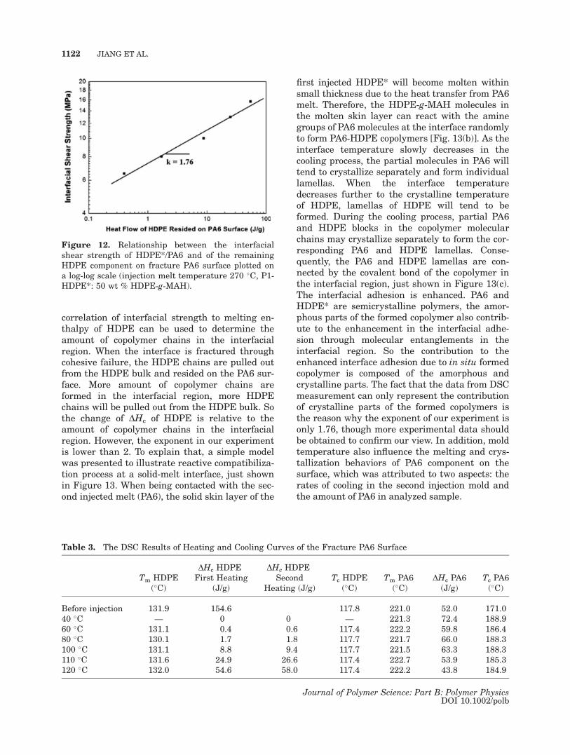
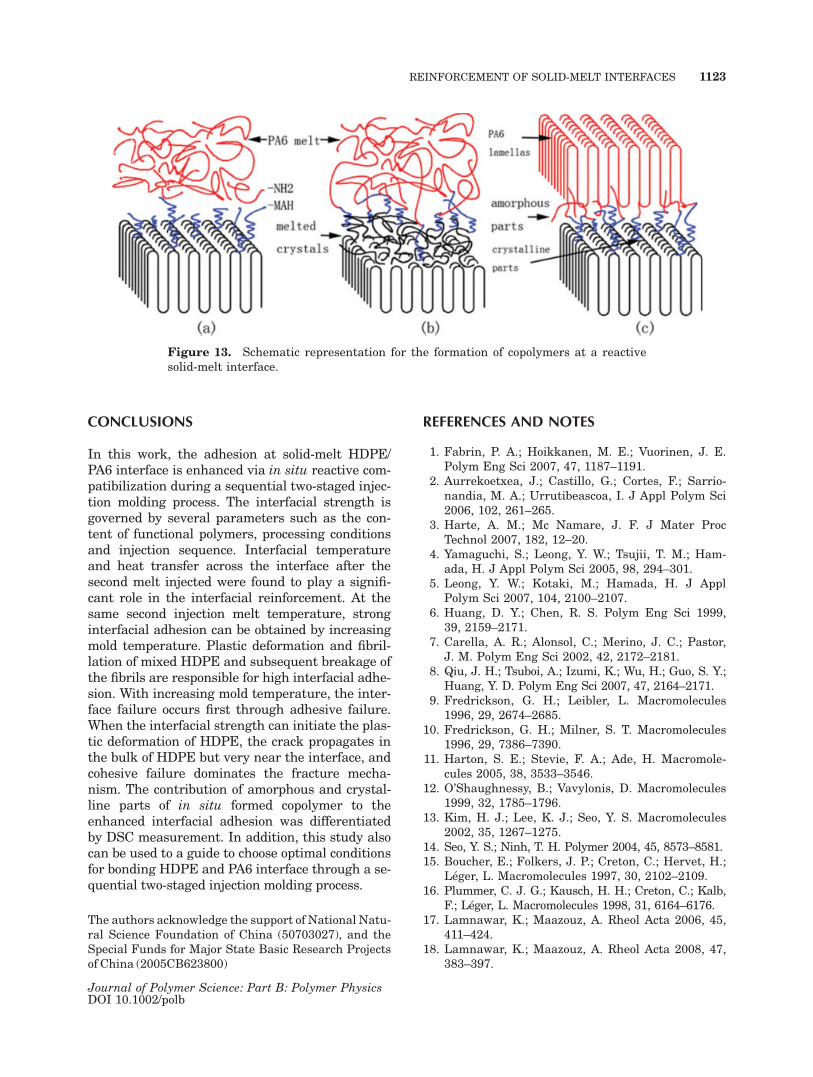
correlation of interfacial strength to melting en-thalpy of HDPE can be used to determine theamount of copolymer chains in the interfacialregion. When the interface is fractured throughcohesive failure, the HDPE chains are pulled outfrom the HDPE bulk and resided on the PA6 sur-face. More amount of copolymer chains areformed in the interfacial region, more HDPEchains will be pulled out from the HDPE bulk. Sothe change of DHc of HDPE is relative to theamount of copolymer chains in the interfacialregion. However, the exponent in our experimentis lower than 2. To explain that, a simple modelwas presented to illustrate reactive compatibiliza-tion process at a solid-melt interface, just shownin Figure 13. When being contacted with the sec-ond injected melt (PA6), the solid skin layer of the
first injected HDPE* will become molten withinsmall thickness due to the heat transfer from PA6melt. Therefore, the HDPE-g-MAH molecules inthe molten skin layer can react with the aminegroups of PA6 molecules at the interface randomlyto form PA6-HDPE copolymers [Fig. 13(b)]. As theinterface temperature slowly decreases in thecooling process, the partial molecules in PA6 willtend to crystallize separately and form individuallamellas. When the interface temperaturedecreases further to the crystalline temperatureof HDPE, lamellas of HDPE will tend to beformed. During the cooling process, partial PA6and HDPE blocks in the copolymer molecularchains may crystallize separately to form the cor-responding PA6 and HDPE lamellas. Conse-quently, the PA6 and HDPE lamellas are con-nected by the covalent bond of the copolymer inthe interfacial region, just shown in Figure 13(c).The interfacial adhesion is enhanced. PA6 andHDPE* are semicrystalline polymers, the amor-phous parts of the formed copolymer also contrib-ute to the enhancement in the interfacial adhe-sion through molecular entanglements in theinterfacial region. So the contribution to theenhanced interface adhesion due to in situ formedcopolymer is composed of the amorphous andcrystalline parts. The fact that the data from DSCmeasurement can only represent the contributionof crystalline parts of the formed copolymers isthe reason why the exponent of our experiment isonly 1.76, though more experimental data shouldbe obtained to confirm our view. In addition, moldtemperature also influence the melting and crys-tallization behaviors of PA6 component on thesurface, which was attributed to two aspects: therates of cooling in the second injection mold andthe amount of PA6 in analyzed sample.
Figure 12. Relationship between the interfacialshear strength of HDPE*/PA6 and of the remainingHDPE component on fracture PA6 surface plotted ona log-log scale (injection melt temperature 270 �C, P1-HDPE*: 50 wt % HDPE-g-MAH).
Table 3. The DSC Results of Heating and Cooling Curves of the Fracture PA6 Surface
Tm HDPE(�C)
DHc HDPEFirst Heating
(J/g)
DHc HDPESecond
Heating (J/g)Tc HDPE
(�C)Tm PA6
(�C)DHc PA6(J/g)
Tc PA6(�C)
Before injection 131.9 154.6 117.8 221.0 52.0 171.040 �C — 0 0 — 221.3 72.4 188.960 �C 131.1 0.4 0.6 117.4 222.2 59.8 186.480 �C 130.1 1.7 1.8 117.7 221.7 66.0 188.3100 �C 131.1 8.8 9.4 117.7 221.5 63.3 188.3110 �C 131.6 24.9 26.6 117.4 222.7 53.9 185.3120 �C 132.0 54.6 58.0 117.4 222.2 43.8 184.9
1122 JIANG ET AL.
Journal of Polymer Science: Part B: Polymer PhysicsDOI 10.1002/polb
CONCLUSIONS
In this work, the adhesion at solid-melt HDPE/PA6 interface is enhanced via in situ reactive com-patibilization during a sequential two-staged injec-tion molding process. The interfacial strength isgoverned by several parameters such as the con-tent of functional polymers, processing conditionsand injection sequence. Interfacial temperatureand heat transfer across the interface after thesecond melt injected were found to play a signifi-cant role in the interfacial reinforcement. At thesame second injection melt temperature, stronginterfacial adhesion can be obtained by increasingmold temperature. Plastic deformation and fibril-lation of mixed HDPE and subsequent breakage ofthe fibrils are responsible for high interfacial adhe-sion. With increasing mold temperature, the inter-face failure occurs first through adhesive failure.When the interfacial strength can initiate the plas-tic deformation of HDPE, the crack propagates inthe bulk of HDPE but very near the interface, andcohesive failure dominates the fracture mecha-nism. The contribution of amorphous and crystal-line parts of in situ formed copolymer to theenhanced interfacial adhesion was differentiatedby DSC measurement. In addition, this study alsocan be used to a guide to choose optimal conditionsfor bonding HDPE and PA6 interface through a se-quential two-staged injection molding process.
The authors acknowledge the support of National Natu-ral Science Foundation of China (50703027), and theSpecial Funds for Major State Basic Research Projectsof China (2005CB623800)
REFERENCES AND NOTES
1. Fabrin, P. A.; Hoikkanen, M. E.; Vuorinen, J. E.Polym Eng Sci 2007, 47, 1187–1191.
2. Aurrekoetxea, J.; Castillo, G.; Cortes, F.; Sarrio-nandia, M. A.; Urrutibeascoa, I. J Appl Polym Sci2006, 102, 261–265.
3. Harte, A. M.; Mc Namare, J. F. J Mater ProcTechnol 2007, 182, 12–20.
4. Yamaguchi, S.; Leong, Y. W.; Tsujii, T. M.; Ham-ada, H. J Appl Polym Sci 2005, 98, 294–301.
5. Leong, Y. W.; Kotaki, M.; Hamada, H. J ApplPolym Sci 2007, 104, 2100–2107.
6. Huang, D. Y.; Chen, R. S. Polym Eng Sci 1999,39, 2159–2171.
7. Carella, A. R.; Alonsol, C.; Merino, J. C.; Pastor,J. M. Polym Eng Sci 2002, 42, 2172–2181.
8. Qiu, J. H.; Tsuboi, A.; Izumi, K.; Wu, H.; Guo, S. Y.;Huang, Y. D. Polym Eng Sci 2007, 47, 2164–2171.
9. Fredrickson, G. H.; Leibler, L. Macromolecules1996, 29, 2674–2685.
10. Fredrickson, G. H.; Milner, S. T. Macromolecules1996, 29, 7386–7390.
11. Harton, S. E.; Stevie, F. A.; Ade, H. Macromole-cules 2005, 38, 3533–3546.
12. O’Shaughnessy, B.; Vavylonis, D. Macromolecules1999, 32, 1785–1796.
13. Kim, H. J.; Lee, K. J.; Seo, Y. S. Macromolecules2002, 35, 1267–1275.
14. Seo, Y. S.; Ninh, T. H. Polymer 2004, 45, 8573–8581.15. Boucher, E.; Folkers, J. P.; Creton, C.; Hervet, H.;
Leger, L. Macromolecules 1997, 30, 2102–2109.16. Plummer, C. J. G.; Kausch, H. H.; Creton, C.; Kalb,
F.; Leger, L. Macromolecules 1998, 31, 6164–6176.17. Lamnawar, K.; Maazouz, A. Rheol Acta 2006, 45,
411–424.18. Lamnawar, K.; Maazouz, A. Rheol Acta 2008, 47,
383–397.
Figure 13. Schematic representation for the formation of copolymers at a reactivesolid-melt interface.
REINFORCEMENT OF SOLID-MELT INTERFACES 1123
Journal of Polymer Science: Part B: Polymer PhysicsDOI 10.1002/polb

19. Bidaux, J. E.; Smith, G. D.; Bernet, N.; Manson,J. A. E.; Hilborn, J. Polymer 1996, 37, 1129–1136.
20. Cho, K.; Li, F. K. Macromolecules 1998, 31,7495–7505.
21. Boucher, E.; Folkers, J. P.; Hervet, H.; Leger, L.Macromolecules 1996, 29, 774–782.
22. Laurens, C.; Creton, C.; Leger, L. Macromolecules2004, 37, 6814–6822.
23. Laurens, C.; Ober, R.; Creton, C.; Leger, L. Macro-molecules 2004, 37, 6806–6813.
24. Arzondo, L. M.; Pino, N.; Carella, J. M.; Pastor, J.M.; Merino, J. C.; Poveda, J.; Alonso, C. PolymEng Sci 2007, 44, 2110–2116.
25. Plummer, C. J. G.; Bourban, P. E.; Zanetto, J. E.;Smith, G. D.; Manson, J. A. E. J Appl Polym Sci2003, 87, 1267–1276.
1124 JIANG ET AL.
Journal of Polymer Science: Part B: Polymer PhysicsDOI 10.1002/polb