Embed Size (px)
DESCRIPTION
reinforcement of concrete plate
Citation preview

Reinforcement for Plates
Course CT4150
Lecture12
5 Jan. 2010

Normal forces in concrete plates
• Only rebars in the x and y directions
• Equilibrium of a plate part

• Equations
• Design
Choose such that nsx+nsy is minimal
(lower bound theorem)
2cos
sin cos
xx sx c
yy sy c
xy c
n n n
n n n
n n

• Solution

Example 1• Situation
nxx=1200, nyy=-200, nxy=-400 kN/m
fy = 500 N/mm², f’c= 30 N/mm²Thickness = 100 mm• Reinforcement
nsx= 1200+400 = 1600 kN/m
nsy= -200+400 = 200• Concrete
nc= -2x400 = -800 kN/m

Asx=1600/500 = 3.20 mm = 3200 mm²/m
212–280 = 2/4x12²x1000/280 = 3231 OK
Asy=200/500 = 0.40 mm = 400 mm²/m
26–500 = 2/4x6²x1000/500 = 452 OK
c = 800/100 = 8 N/mm² < f’c OK
(safety factors omitted)
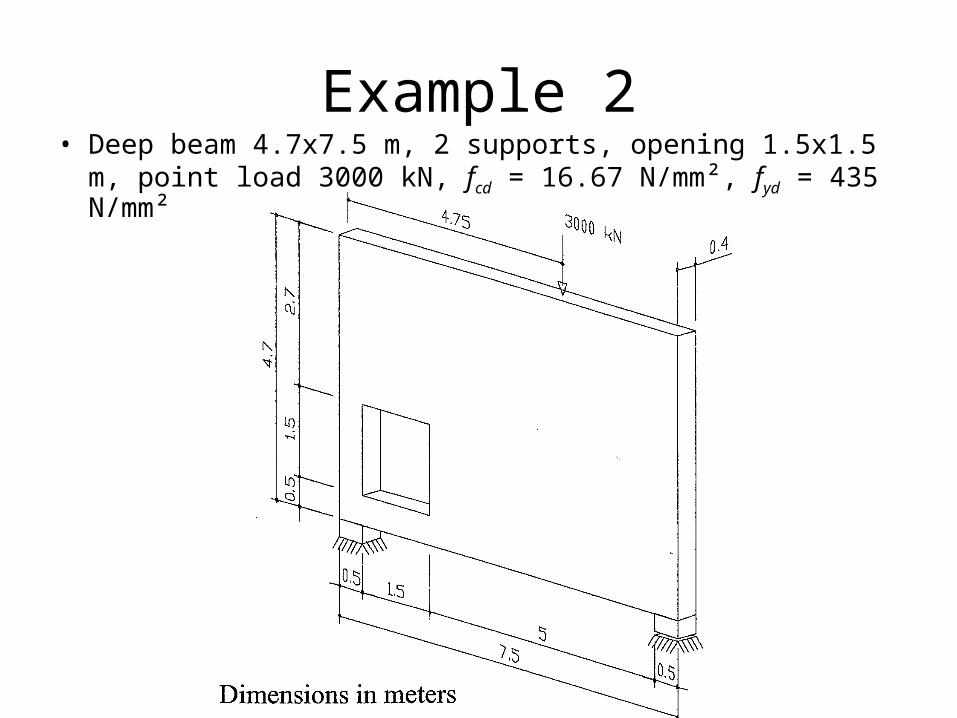
Example 2• Deep beam 4.7x7.5 m, 2 supports, opening 1.5x1.5 m,
point load 3000 kN, fcd = 16.67 N/mm², fyd = 435 N/mm²

• Forces nxx, nyy, nxy (linear elastic analysis)
• Principal stresses

• Reinforcement requirements (software)


• Reinforcement (engineer)

Moments in concrete plates• Only rebars in the x and y directions• Equilibrium of a plate part
• Result (Yield contour)2 min{( )( ), ( )( )}xy px xx py yy px xx py yym m m m m m m m m


Example 3
• Moments in a point
mxx = 13, myy = -8, mxy = 5 kNm/m• Moment capacities
mpx = 17, mpy = 0, m’px =0, m’py = 10• Is the capacity sufficient?
• Yes
25 ?min{(17 13)(0 8), (0 13)(10 8)}
25 ?min{32,26}

Design of moment reinforcement
• Carry the moments with the least amount of reinforcement.
• So, minimize mpx+ mpy+ m’px+ m’py
• 5 constraints• mpx, mpy, m’px, m’py ≥ 0•
Solution 1 (Wood-Armer moments)•
• Crack direction 45º to the reinforcing bars
px xx xy px xx xy
py yy xy py yy xy
m m m m m m
m m m m m m
2 min{( )( ), ( )( )}xy px xx py yy px xx py yym m m m m m m m m

Solution 2 (when mpx would be < 0)
Solution 3 (when mpy would be < 0)2
0
xypx xx
yy
py
mm m
n
m
2
0px
xypy yy
xx
m
mm m
m

Solution 4 (when m’px would be < 0)
Solution 5 (when m’py would be < 0)
2
0px
xypy yy
xx
m
mm m
m
2
0
xypx xx
yy
py
mm m
m
m

Solution 6 (when mpx and mpy would be < 0)
Solution 7 (when m’px and m’py would be < 0)
0
0
px
py
m
m
0
0
px
py
m
m

Example 4
• Moments in a point (as in example 1)
mxx = 13, myy = -8, mxy = 5 kNm/m• Moment capacities
mpx = 13+5²/8 = 16.13 m’px = 0
mpy = 0 m’py = 8+5²/13 = 9.92• Amount of reinforcement is proportional to16.13+0+0+9.92 = 26• Amount of reinforcement in example 317+0+0+10 = 27 (larger, so not optimal)

Example 5
• Plate bridge, simply supported
• 4 x 8 m, point load 80 kN, thick 0.25 m

Example 5 continued
• Decomposition of the load

Example 5 Torsion moment
12
18
10 kNm/m
xy
xy
m a Va T
m F
xyV mxyV m
1
2T
1
2T
1
2T Fa
x

Example 5 All moments
• Moments in the bridge middle
• Moments at the bridge support
14 1
2
18
240 kNm/m
0
10 kNm/m
xx
yy
xy
F am F
am
m F
18
0
0
10 kNm/m
xx
yy
xy
m
m
m F

Example 5 FEM moments


Example 5 Reinforcement
Middle Support Designed
2
40 10 50 kNm/m 0 10 10 50
0 10 10 0 10 10 10
40 10 0 0 10 10 10
100 2.5 0 10 10 10
40
px px px
py py py
px px px
py py py
m m m
m m m
m m m
m m m
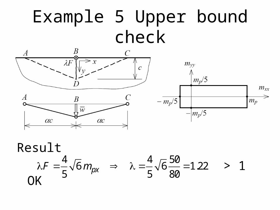
Example 5 Upper bound check
Result
> 1OK
4 4 506 6 1.22
5 5 80pxF m

Computed requirements


ConclusionsThe design procedure used is1 Compute the force flow linear elastically2 Choose the dimensions plastically
The reason for the linear elastic analysis in the firststep is that it shows us how an as yet imperfectdesign can be improved. A plastic (or nonlinear)analysis in step 1 would shows us how thestructure would collapse; but that is not what wewant to know in design.
This procedure is applied to design many types ofstructure for the ULS.