Embed Size (px)
Citation preview
WESTERN FEDERAL LANDS HIGHWAY DIVISION
DETAIL APPROVED FOR USE 11/2006
REVISED:
HEADWALL
REINFORCED CONCRETE
W601-10
11.1
10.4
9.5
8.8
8.0
7.3
6.7
5.9
5.3
4.6
4.0
3.4
10.2
9.5
8.8
8.1
7.5
6.8
6.2
5.6
5.0
4.4
3.8
3.4
9.8
9.2
8.5
7.9
7.2
6.6
6.0
5.4
4.8
4.3
3.7
3.0
9.7
9.0
8.4
7.7
7.1
6.5
5.9
5.3
4.8
4.2
3.7
2.7
10.3
10.0
9.1
8.5
7.9
6.8
6.3
5.7
5.0
4.5
4.0
3.5
9.4
9.2
8.3
7.8
7.3
6.3
5.9
5.3
4.7
4.2
3.8
3.3
9.1
8.8
8.0
7.5
7.0
6.1
5.7
5.2
4.6
4.1
3.7
3.2
8.9
8.6
7.9
7.4
6.9
6.0
5.6
5.1
4.5
4.1
3.6
3.2
180"
168"
156"
144"
132"
120"
108"
96"
84"
72"
60"
48"
16'-3" x 10'-10"
15'-4" x 10'-4"
13'-11" x 8'-7"
12'-10" x 8'-4"
11'-5" x 7'-3"
9'-6" x 6'-5"
8'-2" x 5'-9"
7'-0" x 5'-1"
6'-1" x 4'-7"
7.3
6.6
6.2
5.8
5.0
4.4
4.0
3.5
3.2
7.5
6.8
6.4
6.0
5.2
4.6
4.2
3.7
3.4
8.3
7.6
7.1
6.7
5.8
5.1
4.7
4.1
3.7
9.5
9.3
8.7
8.2
7.1
6.2
5.7
5.0
4.6
are based on a 3 foot cut-off wall and 1:1.5 fill
Reinforcing steel is estimated at 68 lb/cuyd of
CONCRETE (cuyd)
CONCRETE (cuyd)
minim
um
3'-0"
equally s
paced
#4 B
ars
inch.43CONCRETE: Chamfer all exposed edges
face of any bar is 2 inches unless otherwise shown.
or A996) deformed billet steel bars conforming to
REINFORCING STEEL: Grade 60 (ASTM A615
into the rock at least 12".
Galvanize in accordance with ASTM A153.
inch83before placing the bedding. Use clean
18" centers (max.)
18" centers (max.)
5'-0"Variable5'-0"
5'-0"Variable5'-0"
5'-0"Variable5'-0"
18" centers (max.)
design - 4" hook
" dia.43
24" splice
36"30"
minim
um
3'-0"
(See
Varies
spaced (
max.
#4 B
ars e
qually
2:16 P
M
17 N
ove
mber 2
014
]U
SC
[
c:\m
yfiles\p
w_production\d
ms43392\Det.
W601-10.d
gn
FEDERAL HIGHWAY ADMINISTRATION
U.S. DEPARTMENT OF TRANSPORTATION
DETAIL
U.S. CUSTOMARY DETAIL
STATE PROJECTNUMBER
SHEET
18" o
n c
enter)
on c
enter)
(m
ax. 18"
18" o
n c
enter)
spaced (
max.
#4 B
ars e
qually
minim
um
3'-0"
(See
Varies
(max. spacing 1'-6" on center)
#4 Bars equally spaced both w
ays
2"
6"
6"
splice
2'-0"
splice
2'-0"
(max. spacing 1'-6" on center)
#4 Bars equally spaced both w
ays
2"
6"
6"
(max. spacing 18" on center)
#4 Bars equally spaced both w
ays
6"
6"
2"
splice
2'-0"
6"
12" m
in."2
12
"4
3
"2
12
2" 6"
2'-0"
6"
2"
2'-0"
2"
6"
2'-0"
2" key
NO SCALE
Span
Dia
meter
Dia
meter
8.
7.
6.
5.
4.
3.
2.
1.
HEADWALL
REINFORCED CONCRETE
STEP BEVEL PIPE ARCH CULVERT
Skew Angle
0° 15° 30° 45°90°
NOTE:
CL
TYPE A STEP BEVEL FOR ROUND PIPE
TYPE B FULL BEVEL FOR ROUND PIPE
STEP BEVEL FOR PIPE ARCH CULVERT
REINFORCED CONCRETE HEADWALL
MULTIPLE PIPE INSTALLATION
ANCHOR BOLT DETAILCONSTRUCTION JOINT DETAIL
SECTION A-A
PIPE-ARCHES ROUND PIPES
DIAGRAM
SKEW ANGLE
SIZE
PIPE
Span x rise
SIZE
PIPE ARCH
A
A
A
A
A
A
Diameter 0° 15° 30° 45° 0° 15° 30° 45°
ROUND PIPE CULVERT
TYPE A STEP BEVEL TYPE B FULL BEVEL
Skew AngleSkew Angle
centerline
Road
way
centerlin
eCulvert
angle
Skew
Var.
1
material
Beddingjoints
construction
Optional
joints
construction
Optionalmaterial
Bedding
Var.
1
Note 4)
as required
Bend anchor bolts
concrete headwall
Surface of
Note 4)
joints
construction
Optional
material
Bedding
Var.
1
Acceptable alternate bolt
bolt
galvanized
Anchor bolts on
Anchor bolts on
Anchor bolts on
AASHTO M 31. The minimum concrete cover to the
BEDDING: Construct a firm and uniform foundation
ESTIMATED QUANTITIES: The concrete quantities
specified in the Special Contract Requirements.
sandy material for bedding unless otherwise
concrete quantities for headwalls not shown.
slopes for each of the skew angles. Interpolate
concrete excluding the weight of the anchor bolts.
ANCHOR BOLTS: Conform to ASTM A307-04.
be reduced in solid rock, provided wall is keyed
CUTOFF WALLS: The minimum depth shown may
Special Contract Requirements.
recommendations unless otherwise specified in the
the height or step conform to manufacturer's
STEP BEVEL: The variable dimension indicated for
Special Contract Requirements.
for round pipe unless otherwise specified in the
HEADWALL TYPE: Use type A Step Bevel headwalls
150600
150
50
50
150
600
150
150
50
50
50
150
150
600
150
50
600 splice
64
20
64
WESTERN FEDERAL LANDS HIGHWAY DIVISION
WM601-10
DETAIL APPROVED FOR USE 11/2006
REVISED:
HEADWALL
REINFORCED CONCRETE
splice
600
splice
600
150
splice
600
minim
um
900
(max. spacing 450 on center)
#13 Bars equally spaced both w
ays
(max. spacing 450 on center)
#13 Bars equally spaced both w
ays
(max. spacing 450 on center)
#13 Bars equally spaced both w
ays 300 (
min.)
150
4955 x 3300
4675 x 3150
4240 x 2615
3910 x 2540
3480 x 2210
2845 x 1905
2415 x 1700
2060 x 1500
1855 x 1400
5.6
5.0
4.7
4.5
3.8
3.4
3.1
2.7
2.4
5.7
5.2
4.9
4.6
4.0
3.5
3.2
2.8
2.6
6.3
5.8
5.4
5.1
4.4
3.9
3.3
3.1
2.8
7.3
7.1
6.7
6.3
5.4
4.7
4.4
3.8
3.5
4500
4200
3900
3600
3300
3000
2700
2400
2100
1800
1500
1200
8.5
8.0
7.3
6.7
6.1
5.6
5.1
4.5
4.1
3.5
3.1
2.7
7.8
7.3
6.7
6.2
5.7
5.2
4.7
4.3
3.8
3.4
2.9
2.7
7.5
7.0
6.5
6.0
5.5
5.0
4.6
4.1
3.7
3.3
2.8
2.4
7.4
6.9
6.4
5.9
5.4
5.0
4.5
4.1
3.7
3.2
2.8
2.2
7.8
7.6
7.0
6.5
6.0
5.2
4.8
4.4
3.8
3.4
3.1
2.8
7.2
7.0
6.3
6.0
5.6
4.8
4.5
4.1
3.6
3.2
2.9
2.6
7.0
6.7
6.1
5.7
5.4
4.7
4.4
4.0
3.5
3.1
2.8
2.5
6.8
6.6
6.0
5.7
5.3
4.6
4.3
3.9
3.4
3.1
2.8
2.5
10.
9.
CONCRETE (m3)
CONCRETE (m3)
equally s
paced
#13 B
ars
M20
design - 100 mm hook
face of any bar is 50 mm unless otherwise shown.
into the rock at least 300 mm.
or A996M) deformed billet steel bars conforming to
REINFORCING STEEL: Grade 420 (ASTM A615M
CONCRETE: Chamfer all exposed edges 20 mm.
Galvanize in accordance with ASTM A153M.
before placing the bedding. Use clean 10 mm
are based on a 900 mm cut-off wall and 1:1.5 fill
Reinforcing steel is estimated at 32 kg/m3 of
Dimensions without units are millimeters.
when metric sizes are unavailable.
Equivalent US Customary sizes may be used
Furnish hardware in the metric sizes shown.
450 mm centers (max.)
450 mm centers (max.)
450 mm centers (max.)
(See
Varies
minim
um
900
spaced (
max.
#13 B
ars e
qually
450 m
m o
n c
enter)
1500Variable1500
1500Variable1500
1500Variable1500
on c
enter)
(m
ax. 450 m
m
spaced (
max.
#13 B
ars e
qually
750 900
50 key
450 m
m o
n c
enter)
FEDERAL HIGHWAY ADMINISTRATION
U.S. DEPARTMENT OF TRANSPORTATION
METRIC DETAIL
DETAIL
]M
etric
[
c:\m
yfiles\p
w_production\d
ms43392\Det.
W601-10.d
gn
2:24 P
M
17 N
ove
mber 2
014
STATE PROJECTNUMBER
SHEET
minim
um
900
(See
Varies
NO SCALE
Span
Dia
meter
Dia
meter
8.
7.
6.
5.
4.
3.
2.
1.
HEADWALL
REINFORCED CONCRETE
STEP BEVEL PIPE ARCH CULVERT
Skew Angle
0° 15° 30° 45°90°
NOTE:
CL
TYPE A STEP BEVEL FOR ROUND PIPE
TYPE B FULL BEVEL FOR ROUND PIPE
STEP BEVEL FOR PIPE ARCH CULVERT
REINFORCED CONCRETE HEADWALL
MULTIPLE PIPE INSTALLATION
ANCHOR BOLT DETAILCONSTRUCTION JOINT DETAIL
SECTION A-A
PIPE-ARCHES ROUND PIPES
DIAGRAM
SKEW ANGLE
SIZE
PIPE
Span x rise
SIZE
PIPE ARCH
A
A
A
A
A
A
Diameter 0° 15° 30° 45° 0° 15° 30° 45°
ROUND PIPE CULVERT
TYPE A STEP BEVEL TYPE B FULL BEVEL
Skew AngleSkew Angle
centerline
Road
way
centerlin
eCulvert
angle
Skew
Var.
1
material
Beddingjoints
construction
Optional
joints
construction
Optionalmaterial
Bedding
Var.
1N
ote 4)
as required
Bend anchor bolts
concrete headwall
Surface of
Note 4)
joints
construction
Optional
material
Bedding
Var.
1
Acceptable alternate bolt
bolt
galvanized
Anchor bolts on
Anchor bolts on
Anchor bolts on
AASHTO M 31. The minimum concrete cover to the
BEDDING: Construct a firm and uniform foundation
ESTIMATED QUANTITIES: The concrete quantities
specified in the Special Contract Requirements.
sandy material for bedding unless otherwise
concrete quantities for headwalls not shown.
slopes for each of the skew angles. Interpolate
concrete excluding the weight of the anchor bolts.
ANCHOR BOLTS: Conform to ASTM A307-04.
be reduced in solid rock, provided wall is keyed
CUTOFF WALLS: The minimum depth shown may
Special Contract Requirements.
recommendations unless otherwise specified in the
the height or step conform to manufacturer's
STEP BEVEL: The variable dimension indicated for
Special Contract Requirements.
for round pipe unless otherwise specified in the
HEADWALL TYPE: Use type A Step Bevel headwalls
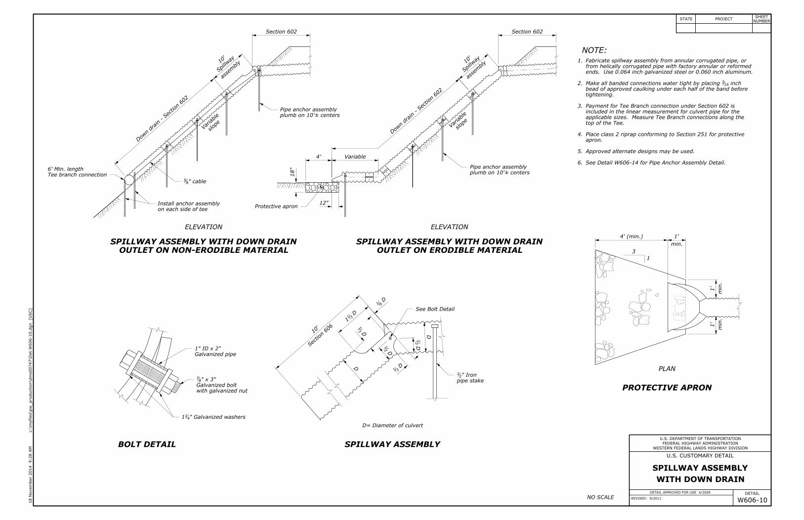
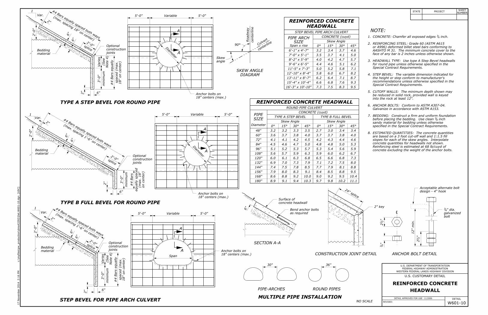
ends. Use 0.064 inch galvanized steel or 0.060 inch aluminum.
See Detail W606-14 for Pipe Anchor Assembly Detail.
plumb on 10'± centers
6' Min. length
10'
10'
plumb on 10'± centers
1" ID x 2"
WESTERN FEDERAL LANDS HIGHWAY DIVISION
WITH DOWN DRAIN
SPILLWAY ASSEMBLY
DETAIL APPROVED FOR USE 4/2009
REVISED: 9/2011 W606-10
inch 163Make all banded connections water tight by placing
" Iron21
" cable85
" Galvanized washers411
4'
18"
12"
Section 606
10'
" x 3" 87
min.
1'
min.
1'
min.
1'
4' (min.)
9:28 A
M
18 N
ove
mber 2
014
]U
SC
[
c:\m
yfiles\p
w_production\d
ms00747\Det.
W606-10.d
gn
FEDERAL HIGHWAY ADMINISTRATION
U.S. DEPARTMENT OF TRANSPORTATION
DETAIL
U.S. CUSTOMARY DETAIL
STATE PROJECTNUMBER
SHEET
D= Diameter of culvert
1
3
NOTE:
ELEVATION ELEVATION
PLAN
OUTLET ON NON-ERODIBLE MATERIAL
SPILLWAY ASSEMBLY WITH DOWN DRAIN
OUTLET ON ERODIBLE MATERIAL
SPILLWAY ASSEMBLY WITH DOWN DRAIN
SPILLWAY ASSEMBLYBOLT DETAIL
PROTECTIVE APRON
6.
5.
4.
3.
2.
1.
slop
eVariable
Approved alternate designs may be used.
apron.
Place class 2 riprap conforming to Section 251 for protective
top of the Tee.
applicable sizes. Measure Tee Branch connections along the
included in the linear measurement for culvert pipe for the
Payment for Tee Branch connection under Section 602 is
tightening.
bead of approved caulking under each half of the band before
from helically corrugated pipe with factory annular or reformed
Fabricate spillway assembly from annular corrugated pipe, or
NO SCALE
Tee branch connection
Pipe anchor assembly
See Bolt Detail
Galvanized pipe
with galvanized nut
Galvanized bolt pipe stake
Pipe anchor assembly
asse
mbly
Spillw
ay
Variable
asse
mbly
Spill
way
Dow
n drain - Section 602
Section 602
D D31
D2
1
D3
1
D31
1
D61
D
D3
1
Section 602
Dow
n drain - Section 602
slop
eVariable
on each side of tee
Install anchor assemblyProtective apron
8.
7.
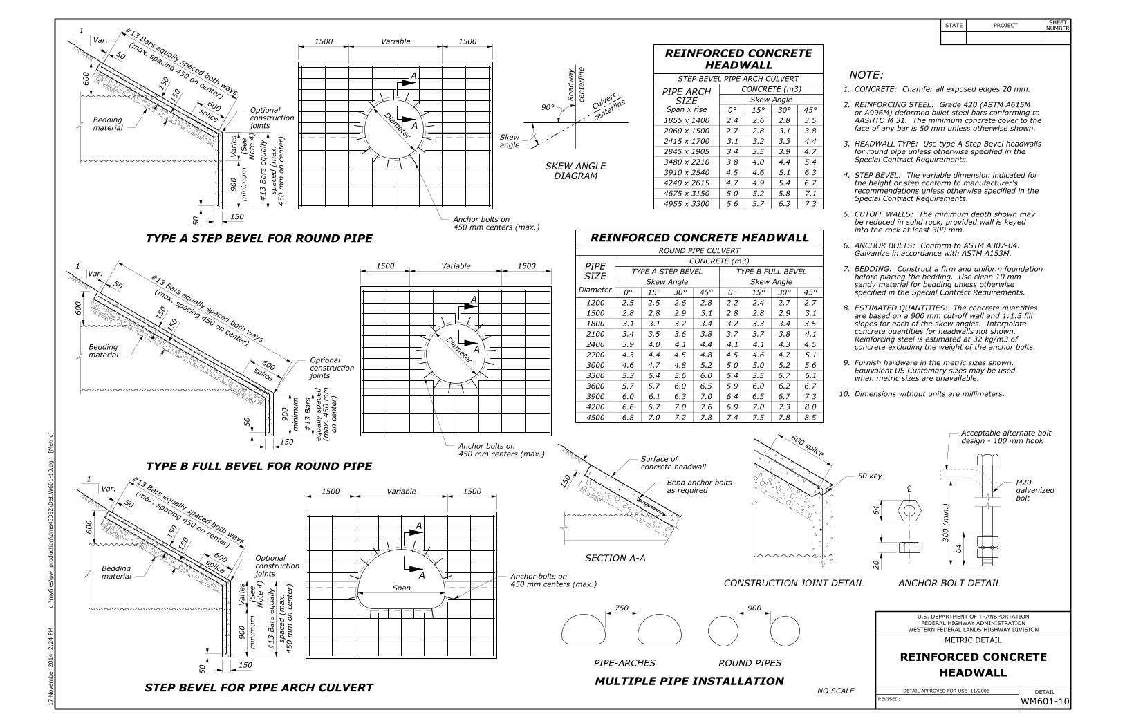
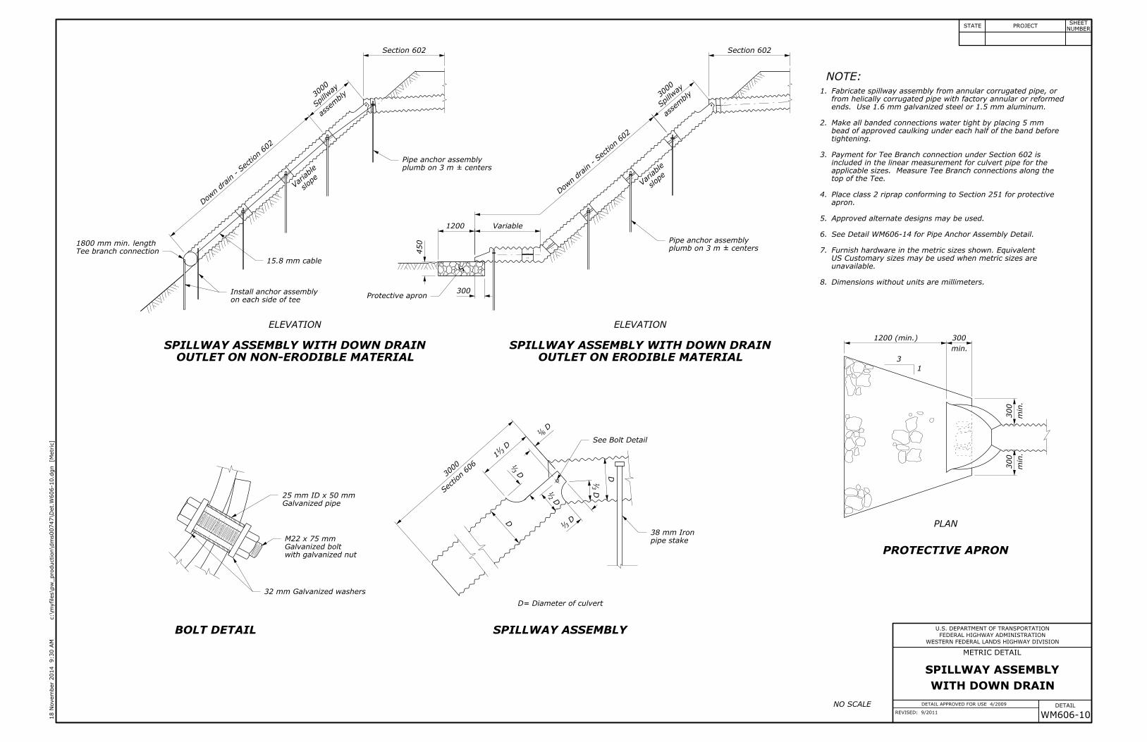
Dimensions without units are millimeters.
unavailable.
US Customary sizes may be used when metric sizes are
Furnish hardware in the metric sizes shown. Equivalent
See Detail WM606-14 for Pipe Anchor Assembly Detail.
Make all banded connections water tight by placing 5 mm
ends. Use 1.6 mm galvanized steel or 1.5 mm aluminum.
M22 x 75 mm
25 mm ID x 50 mm
38 mm Iron
1800 mm min. length
plumb on 3 m ± centers
plumb on 3 m ± centers
450
300
3000
3000
WESTERN FEDERAL LANDS HIGHWAY DIVISION
WITH DOWN DRAIN
SPILLWAY ASSEMBLY
WM606-10
DETAIL APPROVED FOR USE 4/2009
REVISED: 9/2011
32 mm Galvanized washers
15.8 mm cable
min.
300
min.
300
min.
300
1200 (min.)
Section 606
3000
1200
FEDERAL HIGHWAY ADMINISTRATION
U.S. DEPARTMENT OF TRANSPORTATION
METRIC DETAIL
DETAIL
]M
etric
[
c:\m
yfiles\p
w_production\d
ms00747\Det.
W606-10.d
gn
9:30 A
M
18 N
ove
mber 2
014
STATE PROJECTNUMBER
SHEET
D= Diameter of culvert
1
3
NOTE:
ELEVATION ELEVATION
PLAN
OUTLET ON NON-ERODIBLE MATERIAL
SPILLWAY ASSEMBLY WITH DOWN DRAIN
OUTLET ON ERODIBLE MATERIAL
SPILLWAY ASSEMBLY WITH DOWN DRAIN
SPILLWAY ASSEMBLYBOLT DETAIL
PROTECTIVE APRON
6.
5.
4.
3.
2.
1.
slop
eVariable
Approved alternate designs may be used.
apron.
Place class 2 riprap conforming to Section 251 for protective
top of the Tee.
applicable sizes. Measure Tee Branch connections along the
included in the linear measurement for culvert pipe for the
Payment for Tee Branch connection under Section 602 is
tightening.
bead of approved caulking under each half of the band before
from helically corrugated pipe with factory annular or reformed
Fabricate spillway assembly from annular corrugated pipe, or
NO SCALE
Tee branch connection
Pipe anchor assembly
See Bolt Detail
Galvanized pipe
with galvanized nut
Galvanized bolt pipe stake
Pipe anchor assembly
asse
mbly
Spillw
ay
Variable
asse
mbly
Spill
way
Dow
n drain - Section 602
Section 602
D D31
D2
1
D3
1
D31
1
D61
D
D3
1
Section 602
Dow
n drain - Section 602
slop
eVariable
on each side of tee
Install anchor assemblyProtective apron
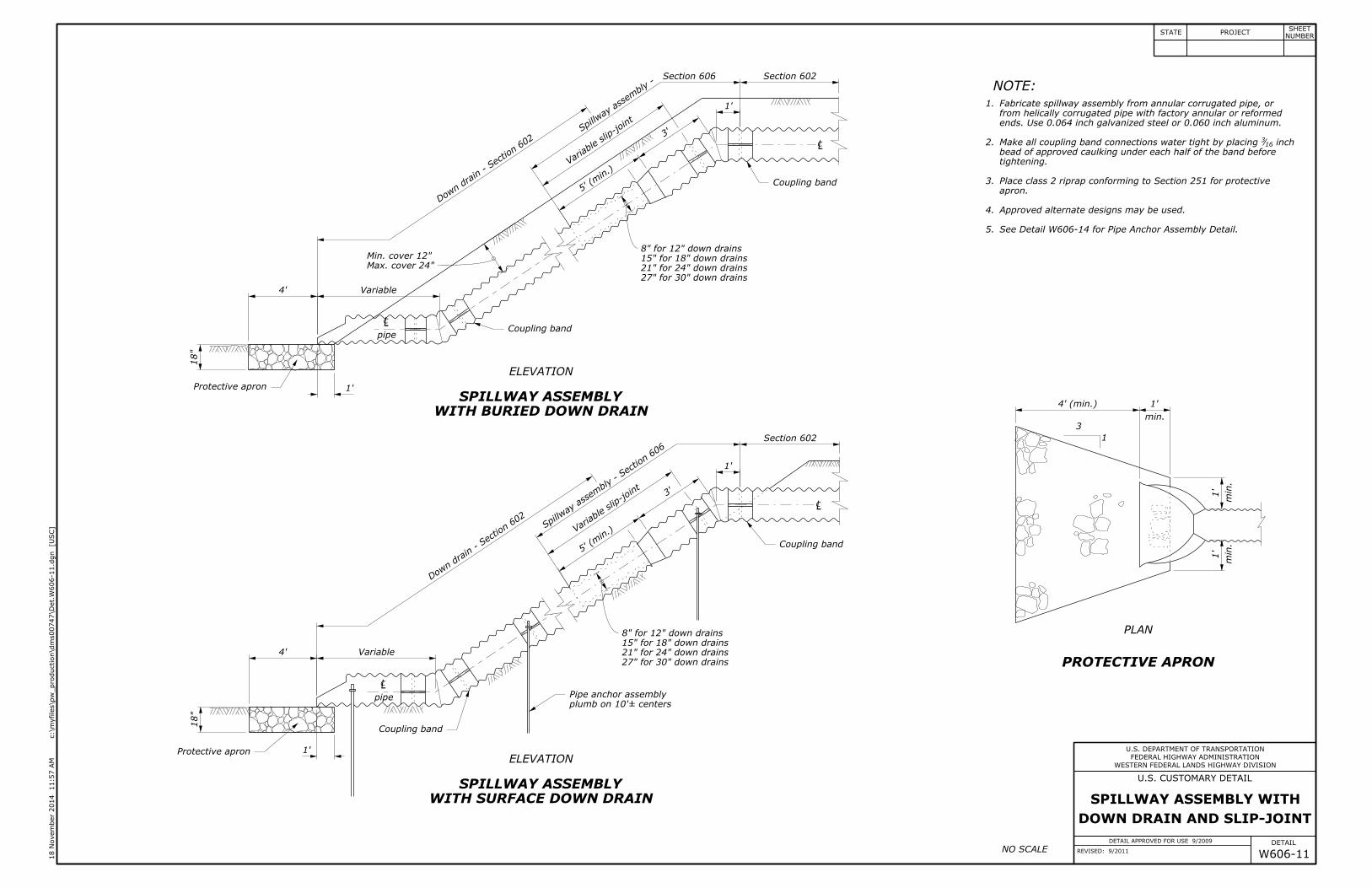
27" for 30" down drains
21" for 24" down drains
15" for 18" down drains
27" for 30" down drains
21" for 24" down drains
15" for 18" down drains
Min. cover 12"
ends. Use 0.064 inch galvanized steel or 0.060 inch aluminum.
See Detail W606-14 for Pipe Anchor Assembly Detail.
plumb on 10'± centers
DOWN DRAIN AND SLIP-JOINT
SPILLWAY ASSEMBLY WITH
WESTERN FEDERAL LANDS HIGHWAY DIVISION
DETAIL APPROVED FOR USE 9/2009
REVISED: 9/2011 W606-11
inch163Make all coupling band connections water tight by placing
1'
3'
5' (
min.)
1'
4'
18"
18"
4'
1'
1'
3'
5' (
min.)
Max. cover 24"
8" for 12" down drains
8" for 12" down drains
min.
1'
4' (min.)
min.
1'
min.
1'
11:57 A
M
18 N
ove
mber 2
014
]U
SC
[
c:\m
yfiles\p
w_production\d
ms00747\Det.
W606-11.d
gn
FEDERAL HIGHWAY ADMINISTRATION
U.S. DEPARTMENT OF TRANSPORTATION
DETAIL
U.S. CUSTOMARY DETAIL
STATE PROJECTNUMBER
SHEET
Dow
n drain - Se
ction 60
2
Spill
way assem
bly -
Section 606
pipe
Dow
n drain - Se
ction 60
2
ELEVATION
ELEVATION
WITH BURIED DOWN DRAIN
SPILLWAY ASSEMBLY
WITH SURFACE DOWN DRAIN
SPILLWAY ASSEMBLY
1
3
PLAN
PROTECTIVE APRON
Approved alternate designs may be used.
apron.
Place class 2 riprap conforming to Section 251 for protective
tightening.
bead of approved caulking under each half of the band before
from helically corrugated pipe with factory annular or reformed
Fabricate spillway assembly from annular corrugated pipe, or
5.
4.
3.
2.
1.
Spill
way assem
bly - Se
ction 60
6
NOTE:
NO SCALE
CL
CLpipe
CL
CL
Pipe anchor assembly
Protective apron
Coupling band
Protective apron
Coupling band
Coupling band
Coupling band
Variable
Varia
ble slip-joint
Section 602
Section 602
Varia
ble slip-joint
Variable
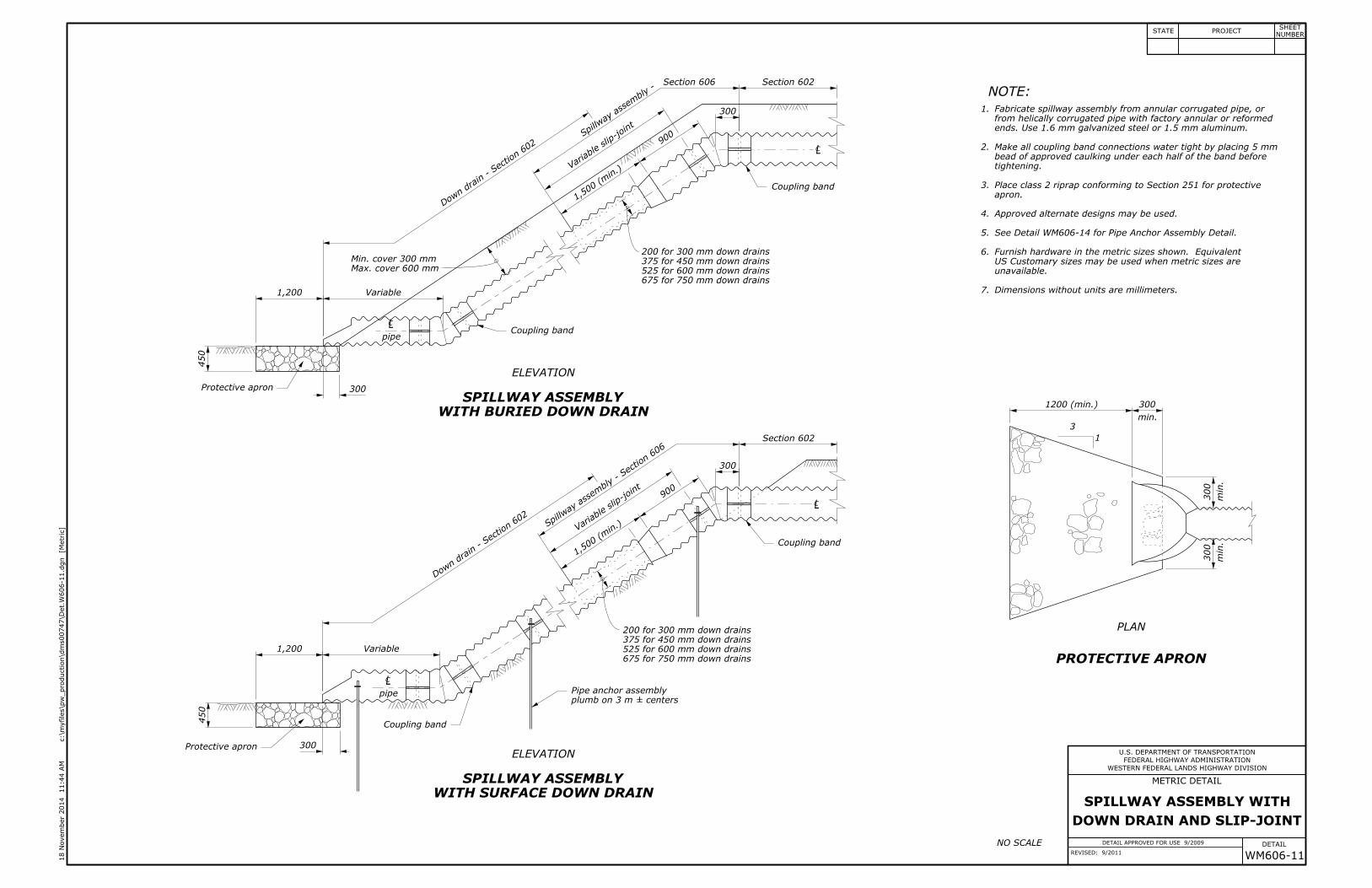
675 for 750 mm down drains
525 for 600 mm down drains
375 for 450 mm down drains
675 for 750 mm down drains
525 for 600 mm down drains
375 for 450 mm down drains
7.
6.
Dimensions without units are millimeters.
unavailable.
US Customary sizes may be used when metric sizes are
Furnish hardware in the metric sizes shown. Equivalent
See Detail WM606-14 for Pipe Anchor Assembly Detail.
Make all coupling band connections water tight by placing 5 mm
ends. Use 1.6 mm galvanized steel or 1.5 mm aluminum.
DOWN DRAIN AND SLIP-JOINT
SPILLWAY ASSEMBLY WITH
Min. cover 300 mm
plumb on 3 m ± centers
WESTERN FEDERAL LANDS HIGHWAY DIVISION
WM606-11
DETAIL APPROVED FOR USE 9/2009
REVISED: 9/2011
300
900
1,50
0 (min.)
300
300
1,200
900
1,50
0 (min.)
300
200 for 300 mm down drains
Max. cover 600 mm
min.
300
1200 (min.)
min.
300
min.
300
200 for 300 mm down drains
450
1,200
450
FEDERAL HIGHWAY ADMINISTRATION
U.S. DEPARTMENT OF TRANSPORTATION
METRIC DETAIL
DETAIL
]M
etric
[
c:\m
yfiles\p
w_production\d
ms00747\Det.
W606-11.d
gn
11:44 A
M
18 N
ove
mber 2
014
STATE PROJECTNUMBER
SHEET
Dow
n drain - Se
ction 60
2
Spill
way assem
bly -
Section 606
pipe
Dow
n drain - Se
ction 60
2
ELEVATION
ELEVATION
WITH BURIED DOWN DRAIN
SPILLWAY ASSEMBLY
WITH SURFACE DOWN DRAIN
SPILLWAY ASSEMBLY
1
3
PLAN
PROTECTIVE APRON
Approved alternate designs may be used.
apron.
Place class 2 riprap conforming to Section 251 for protective
tightening.
bead of approved caulking under each half of the band before
from helically corrugated pipe with factory annular or reformed
Fabricate spillway assembly from annular corrugated pipe, or
5.
4.
3.
2.
1.
Spill
way assem
bly - Se
ction 60
6
NOTE:
NO SCALE
CL
CLpipe
CL
CL
Pipe anchor assembly
Protective apron
Coupling band
Protective apron
Coupling band
Coupling band
Coupling band
Variable
Varia
ble slip-joint
Section 602
Section 602
Varia
ble slip-joint
Variable
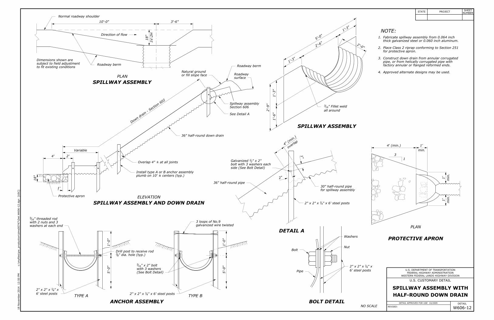
thick galvanized steel or 0.060 inch aluminum.
Fabricate spillway assembly from 0.064 inch
plumb on 10' ± centers (typ.)
30" half-round pipe
3 loops of No.9
HALF-ROUND DOWN DRAIN
SPILLWAY ASSEMBLY WITH
WESTERN FEDERAL LANDS HIGHWAY DIVISION
DETAIL APPROVED FOR USE 10/2009
REVISED: W606-12
Overlap 4" ± at all joints
36" half-round down drain
" x 6' steel posts412" x 2" x
" dia. hole (typ.)83
" x 2" bolt165
" threaded rod165
" x 2"21Galvanized
" Fillet weld163
3'-6"10'-0"
1V:2
H
18"
36" half-round pipe
6' steel posts
" x412" x 2" x
6' steel posts
" x412" x 2" x
" x 6' steel posts412" x 2" x
5'-0"
1'-0"
5'-0"
1'-0"
4' 2'
18"
1'
2"
1"
overlap
4" (
min.)
1'-6"
1'-3"
2'-9"
1'-3"
2'-6"
1'-3"
5'-0"
2'-0"
min.
1'
4' (min.)
min.
1'
min.
1'
12:50 P
M
18 N
ove
mber 2
014
]U
SC
[
c:\m
yfiles\p
w_production\d
ms00747\Det.
W606-12.d
gn
FEDERAL HIGHWAY ADMINISTRATION
U.S. DEPARTMENT OF TRANSPORTATION
DETAIL
U.S. CUSTOMARY DETAIL
STATE PROJECTNUMBER
SHEET
PLAN
ELEVATION
TYPE A TYPE B
DETAIL A
BOLT DETAIL
SPILLWAY ASSEMBLY
SPILLWAY ASSEMBLY
SPILLWAY ASSEMBLY AND DOWN DRAIN
ANCHOR ASSEMBLY
4.
3.
2.
1.
Approved alternate designs may be used.
factory annular or flanged reformed ends.
pipe, or from helically corrugated pipe with
Construct down drain from annular corrugated
for protective apron.
Place Class 2 riprap conforming to Section 251
to fit existing conditions
subject to field adjustment
Dimensions shown are
Roadway
1
3
PLAN
PROTECTIVE APRON
Dow
n drain - Se
ction 60
2
NOTE:
NO SCALE
Direction of flow
all around
Normal roadway shoulder
Roadway berm
or fill slope face
Natural ground
Roadway berm
surface
See Detail A
Install type A or B anchor assembly
Protective apron
Section 606
Spillway assembly
side (See Bolt Detail)
bolt with 3 washers each
for spillway assembly
galvanized wire twisted
(See Bolt Detail)
with 3 washers
Bolt
Pipe
Washers
Nut
washers at each end
with 2 nuts and 3
Drill post to receive rod
Variable
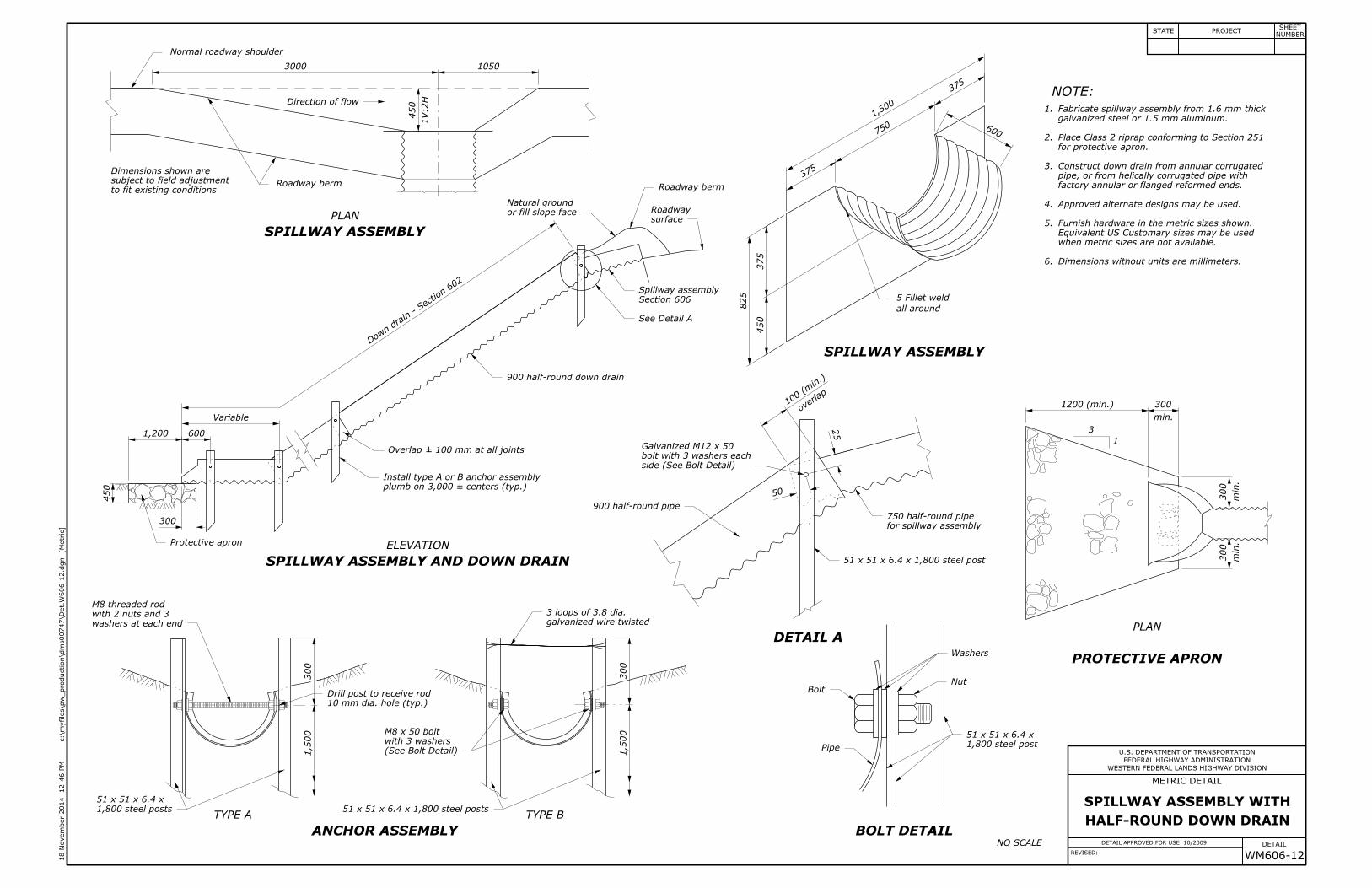
HALF-ROUND DOWN DRAIN
SPILLWAY ASSEMBLY WITH
5 Fillet weld
6.
5.
Dimensions without units are millimeters.
when metric sizes are not available.
Equivalent US Customary sizes may be used
Furnish hardware in the metric sizes shown.
galvanized steel or 1.5 mm aluminum.
Fabricate spillway assembly from 1.6 mm thick
plumb on 3,000 ± centers (typ.)
Galvanized M12 x 50
750 half-round pipe
M8 threaded rod
10 mm dia. hole (typ.)
M8 x 50 bolt
3 loops of 3.8 dia.
WESTERN FEDERAL LANDS HIGHWAY DIVISION
WM606-12
DETAIL APPROVED FOR USE 10/2009
REVISED:
10503000
Overlap ± 100 mm at all joints
900 half-round down drain
900 half-round pipe
1,800 steel posts
51 x 51 x 6.4 x
1,800 steel post
51 x 51 x 6.4 x
51 x 51 x 6.4 x 1,800 steel post
51 x 51 x 6.4 x 1,800 steel posts
1,5
00
300
1,5
00
300
1,200 600
300
450
50
25
overlap
100 (min.)
450
375
825
375
750
375
1,50
0
600
min.
300
1200 (min.)
min.
300
min.
300
1V:2
H
450
FEDERAL HIGHWAY ADMINISTRATION
U.S. DEPARTMENT OF TRANSPORTATION
METRIC DETAIL
DETAIL
]M
etric
[
c:\m
yfiles\p
w_production\d
ms00747\Det.
W606-12.d
gn
12:46 P
M
18 N
ove
mber 2
014
STATE PROJECTNUMBER
SHEET
PLAN
ELEVATION
TYPE A TYPE B
DETAIL A
BOLT DETAIL
SPILLWAY ASSEMBLY
SPILLWAY ASSEMBLY
SPILLWAY ASSEMBLY AND DOWN DRAIN
ANCHOR ASSEMBLY
4.
3.
2.
1.
Approved alternate designs may be used.
factory annular or flanged reformed ends.
pipe, or from helically corrugated pipe with
Construct down drain from annular corrugated
for protective apron.
Place Class 2 riprap conforming to Section 251
to fit existing conditions
subject to field adjustment
Dimensions shown are
Roadway
1
3
PLAN
PROTECTIVE APRON
Dow
n drain - Se
ction 60
2
NOTE:
NO SCALE
Direction of flow
all around
Normal roadway shoulder
Roadway berm
or fill slope face
Natural ground
Roadway berm
surface
See Detail A
Install type A or B anchor assembly
Protective apron
Section 606
Spillway assembly
side (See Bolt Detail)
bolt with 3 washers each
for spillway assembly
galvanized wire twisted
(See Bolt Detail)
with 3 washers
Bolt
Pipe
Washers
Nut
washers at each end
with 2 nuts and 3
Drill post to receive rod
Variable
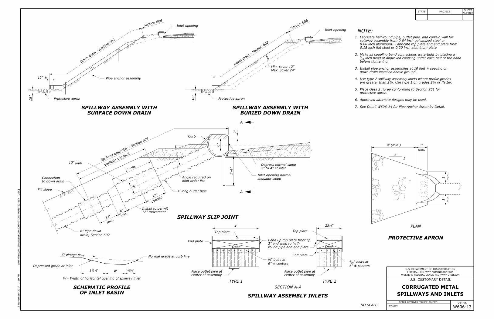
0.18 inch flat steel or 0.20 inch aluminum plate.
0.60 inch aluminum. Fabricate top plate and end plate from
spillway assembly from 0.64 inch galvanized steel or
Install pipe anchor assemblies at 10 feet ± spacing on
6" ± centers
" bolts at165
6" ± centers
" bolts at83
2" and weld to half-
2" to 4" at inlet
12" movement
8" Pipe down
Max. cover 24"
See Detail W606-14 for Pipe Anchor Assemby Detail.
SPILLWAYS AND INLETS
CORRUGATED METAL
WESTERN FEDERAL LANDS HIGHWAY DIVISION
DETAIL APPROVED FOR USE 10/2009
REVISED: W606-13
inch bead of approved caulking under each half of the band163
4' long outlet pipe
10" pipe
18"
12" ±
2' min.
8"
overlap
12"
min.
12" m
in.6"
1'-4"
6"
2"
18"
4'
Min. cover 12"
min.
1'
4' (min.)
min.
1'
min.
1'
"2125
1:19 P
M
18 N
ove
mber 2
014
]U
SC
[
c:\m
yfiles\p
w_production\d
ms00747\Det.
W606-13.d
gn
FEDERAL HIGHWAY ADMINISTRATION
U.S. DEPARTMENT OF TRANSPORTATION
DETAIL
U.S. CUSTOMARY DETAIL
STATE PROJECTNUMBER
SHEET
OpenOpen
SECTION A-A
A
A
SURFACE DOWN DRAIN
SPILLWAY ASSEMBLY WITH
BURIED DOWN DRAIN
SPILLWAY ASSEMBLY WITH
SPILLWAY ASSEMBLY INLETS
SPILLWAY SLIP JOINT
OF INLET BASIN
SCHEMATIC PROFILE
W= Width of horizontal opening of spillway inlet
Fabricate half-round pipe, outlet pipe, and curtain wall for
Make all coupling band connections watertight by placing a
before tightening.
TYPE 1 TYPE 2
1
3
PLAN
PROTECTIVE APRON
Secti
on 606
Dow
n drain - Se
ction 60
2
Dow
n drain - Se
ction 60
2
Section 60
6
inlet order list
Spillw
ay as
sembly -
Secti
on 606
7.
6.
5.
4.
3.
2.
1.
Approved alternate designs may be used.
protective apron.
Place class 2 riprap conforming to Section 251 for
are greater than 2%. Use type 1 on grades 2% or flatter.
Use type 2 spillway assembly inlets where profile grades
down drain installed above ground.
NOTE:
NO SCALE
Protective apron
Fill slope
shoulder slope
Inlet opening normal
Protective apron
Top plate Top plate
Normal grade at curb line
Depressed grade at inlet
Drainage flow
center of assembly
Place outlet pipe at
Bend up top plate front lip
round pipe and end plate
End plate
center of assembly
Place outlet pipe at
End plate
Inlet opening
Inlet opening
Depress normal slope
to down drain
Connection
drain, Section 602
Pipe anchor assembly
Varia
ble slip joi
nt
Angle required on
Install to permit
Curb
W21
WW211
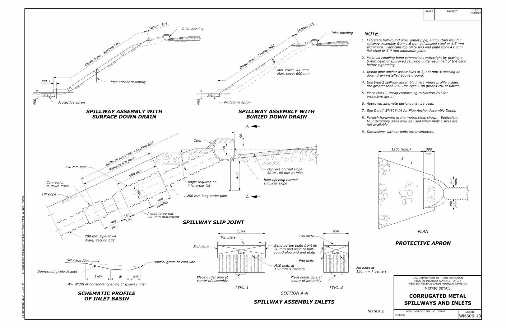
Max. cover 600 mm
9.
8.
flat steel or 5.0 mm aluminum plate.
aluminum. Fabricate top plate and end plate from 4.6 mm
spillway assembly from 1.6 mm galvanized steel or 1.5 mm
5 mm bead of approved caulking under each half of the band
Install pipe anchor assemblies at 3,000 mm ± spacing on
SPILLWAYS AND INLETS
CORRUGATED METAL
50 mm and weld to half-
300 mm movement
200 mm Pipe down
50 to 100 mm at inlet
Dimensions without units are millimeters.
not available.
US Customary sizes may be used when metric sizes are
Furnish hardware in the metric sizes shown. Equivalent
See Detail WM606-14 for Pipe Anchor Assembly Detail.
WESTERN FEDERAL LANDS HIGHWAY DIVISION
WM606-13
DETAIL APPROVED FOR USE 10/2009
REVISED:
150 mm ± centers
M8 bolts at150 mm ± centers
M10 bolts at
1,200 mm long outlet pipe
250 mm pipe
6501,200
400
150
50
overlap
300
200
600
min.
min.
300 m
in.15
0
450
450
Min. cover 300 mm
300 ±
min.
300
1200 (min.)
min.
300
min.
300
FEDERAL HIGHWAY ADMINISTRATION
U.S. DEPARTMENT OF TRANSPORTATION
METRIC DETAIL
DETAIL
]M
etric
[
c:\m
yfiles\p
w_production\d
ms00747\Det.
W606-13.d
gn
1:09 P
M
18 N
ove
mber 2
014
STATE PROJECTNUMBER
SHEET
OpenOpen
SECTION A-A
A
A
SURFACE DOWN DRAIN
SPILLWAY ASSEMBLY WITH
BURIED DOWN DRAIN
SPILLWAY ASSEMBLY WITH
SPILLWAY ASSEMBLY INLETS
SPILLWAY SLIP JOINT
OF INLET BASIN
SCHEMATIC PROFILE
W= Width of horizontal opening of spillway inlet
Fabricate half-round pipe, outlet pipe, and curtain wall for
Make all coupling band connections watertight by placing a
before tightening.
TYPE 1 TYPE 2
1
3
PLAN
PROTECTIVE APRON
Secti
on 606
Dow
n drain - Se
ction 60
2
Dow
n drain - Se
ction 60
2
Section 60
6
inlet order list
Spillw
ay as
sembly -
Secti
on 606
7.
6.
5.
4.
3.
2.
1.
Approved alternate designs may be used.
protective apron.
Place class 2 riprap conforming to Section 251 for
are greater than 2%. Use type 1 on grades 2% or flatter.
Use type 2 spillway assembly inlets where profile grades
down drain installed above ground.
NOTE:
NO SCALE
Protective apron
Fill slope
shoulder slope
Inlet opening normal
Protective apron
Top plate Top plate
Normal grade at curb line
Depressed grade at inlet
Drainage flow
center of assembly
Place outlet pipe at
Bend up top plate front lip
round pipe and end plate
End plate
center of assembly
Place outlet pipe at
End plate
Inlet opening
Inlet opening
Depress normal slope
to down drain
Connection
drain, Section 602
Pipe anchor assembly
Varia
ble slip joi
nt
Angle required on
Install to permit
Curb
W21
WW211

Place slope anchor assemblies on 20' max. centers on slopes
Collar of 2"
"163
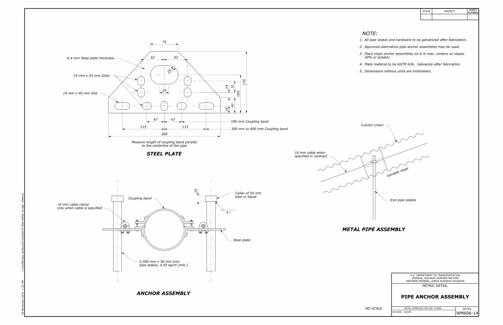
PIPE ANCHOR ASSEMBLY
WESTERN FEDERAL LANDS HIGHWAY DIVISION
DETAIL APPROVED FOR USE 4/2009
REVISED: 9/2009 W606-14
" cable clamp85
" cable when85
" x 1" Slots43
7" Coupling band
" Slots43" x 32
191
" Steel plate thickness41
1"
12"
"214"2
14
"871"8
71
"8
56
"8
14
"8
51"
43
"16
9
"4
11
"212"2
12
3"
1"
R
1"
stakes, 2.72 lbs/ft (min.)
" Iron pipe218' x 1
12" or 24" Coupling band
1:28 P
M
18 N
ove
mber 2
014
]U
SC
[
c:\m
yfiles\p
w_production\d
ms00747\Det.
W606-14.d
gn
FEDERAL HIGHWAY ADMINISTRATION
U.S. DEPARTMENT OF TRANSPORTATION
DETAIL
U.S. CUSTOMARY DETAIL
STATE PROJECTNUMBER
SHEET
to the centerline of the pipe
Measure length of coupling band parallel
Varia
ble sl
ope
ANCHOR ASSEMBLY
STEEL PLATE
METAL PIPE ASSEMBLY
4.
3.
2.
1.
Plate material to be ASTM A36. Galvanize after fabrication.
20% or greater.
Approved alternative pipe anchor assemblies may be used.
All pipe stakes and hardware to be galvanized after fabrication.
NOTE:
NO SCALE
Culvert crown
pipe or equal
Iron pipe stakesCoupling band
Steel plate
only when cable is specified
specified in contract
5
5.
Collar of 50 mm
16 mm cable clamp
16 mm cable when
PIPE ANCHOR ASSEMBLY
Place slope anchor assemblies on 6 m max. centers on slopes
Dimensions without units are millimeters.
WESTERN FEDERAL LANDS HIGHWAY DIVISION
WM606-14
DETAIL APPROVED FOR USE 4/2009
REVISED: 9/2009
pipe stakes, 4.05 kg/m (min.)
2,400 mm x 38 mm Iron
180 mm Coupling band
6.4 mm Steel plate thickness
19 mm x 25 mm Slots
19 mm x 40 mm Slot
300 mm or 600 mm Coupling band
25
75
6262
25
R
25
4747
115115
300
170
105
41
19
14
31
FEDERAL HIGHWAY ADMINISTRATION
U.S. DEPARTMENT OF TRANSPORTATION
METRIC DETAIL
DETAIL
]M
etric
[
c:\m
yfiles\p
w_production\d
ms00747\Det.
W606-14.d
gn
1:25 P
M
18 N
ove
mber 2
014
STATE PROJECTNUMBER
SHEET
to the centerline of the pipe
Measure length of coupling band parallel
Varia
ble sl
ope
ANCHOR ASSEMBLY
STEEL PLATE
METAL PIPE ASSEMBLY
4.
3.
2.
1.
Plate material to be ASTM A36. Galvanize after fabrication.
20% or greater.
Approved alternative pipe anchor assemblies may be used.
All pipe stakes and hardware to be galvanized after fabrication.
NOTE:
NO SCALE
Culvert crown
pipe or equal
Iron pipe stakesCoupling band
Steel plate
only when cable is specified
specified in contract
WESTERN FEDERAL LANDS HIGHWAY DIVISION
DETAIL APPROVED FOR USE 3/2009
REVISED:
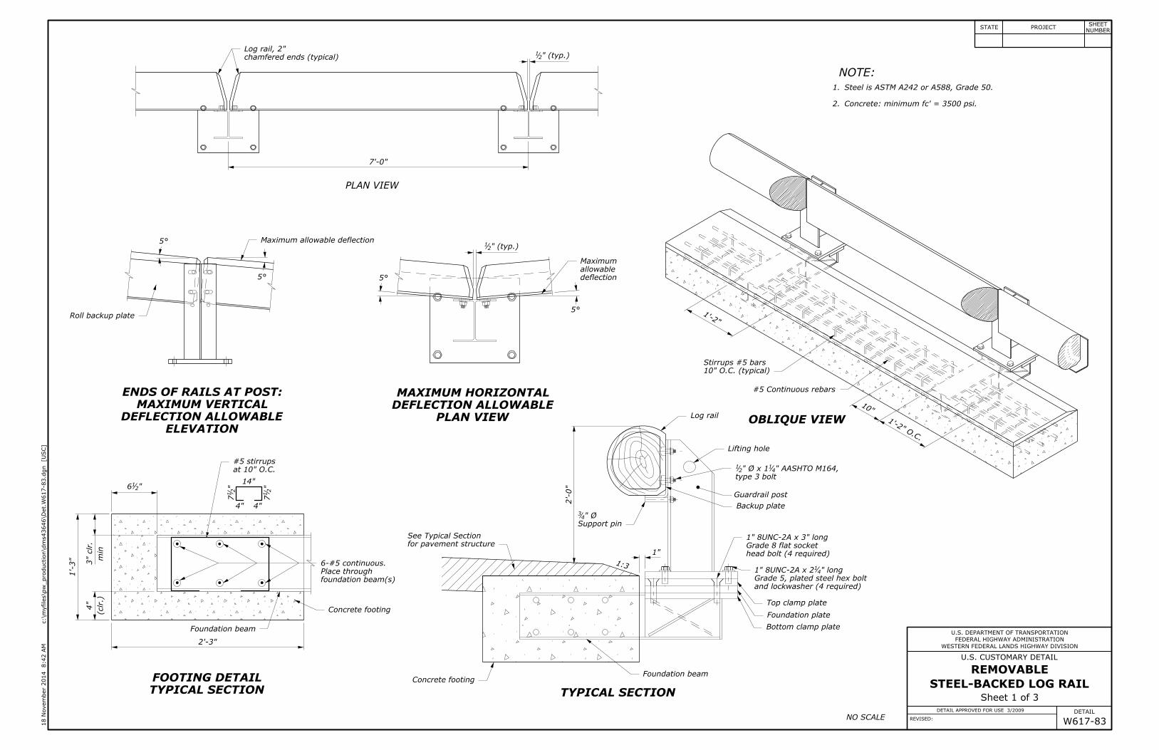
Sheet 1 of 3
STEEL-BACKED LOG RAIL
REMOVABLE
W617-83
Concrete: minimum fc' = 3500 psi.
8:42 A
M
18 N
ove
mber 2
014
]U
SC
[
c:\m
yfiles\p
w_production\d
ms43646\Det.
W617-83.d
gn
FEDERAL HIGHWAY ADMINISTRATION
U.S. DEPARTMENT OF TRANSPORTATION
DETAIL
U.S. CUSTOMARY DETAIL
STATE PROJECTNUMBER
SHEET
7'-0"
1'-2"
10"
1'-2" O.C.
2'-0"
1"
"216
min
3" clr.
1'-3"
(clr.)
4"
2'-3"
14"
"2
17
4"4"
"2
17
at 10" O.C.
#5 stirrups
6-#5 continuous.
" Ø43
10" O.C. (typical)
Stirrups #5 bars
#5 Continuous rebars
" AASHTO M164,41" Ø x 12
1
1" 8UNC-2A x 3" long
" long411" 8UNC-2A x 2
Log rail, 2"" (typ.)2
1
" (typ.)21
NO SCALE
2.
1.
NOTE:
Steel is ASTM A242 or A588, Grade 50.
ELEVATION
DEFLECTION ALLOWABLE
MAXIMUM VERTICAL
ENDS OF RAILS AT POST:
PLAN VIEW
DEFLECTION ALLOWABLE
MAXIMUM HORIZONTAL
TYPICAL SECTION
FOOTING DETAIL
TYPICAL SECTION
OBLIQUE VIEW
chamfered ends (typical)
deflection
allowable
Maximum
Roll backup plate
for pavement structure
See Typical Section
Concrete footing
Foundation beam
Concrete footing
Support pin
Log rail
Lifting hole
type 3 bolt
Backup plate
and lockwasher (4 required)
Grade 5, plated steel hex bolt
Top clamp plate
Foundation plate
Bottom clamp plate
Foundation beam
PLAN VIEW
Guardrail post
1:3
head bolt (4 required)
Grade 8 flat socket
5°
5° 5°
5°
Maximum allowable deflection
foundation beam(s)
Place through
WESTERN FEDERAL LANDS HIGHWAY DIVISION
DETAIL APPROVED FOR USE 3/2009
REVISED:
Sheet 2 of 3
STEEL-BACKED LOG RAIL
REMOVABLE
W617-83
3"
5"
2"
5"
2"4" 4"
8:42 A
M
18 N
ove
mber 2
014
]U
SC
[
c:\m
yfiles\p
w_production\d
ms43646\Det.
W617-83.d
gn
FEDERAL HIGHWAY ADMINISTRATION
U.S. DEPARTMENT OF TRANSPORTATION
DETAIL
U.S. CUSTOMARY DETAIL
STATE PROJECTNUMBER
SHEET
6'-11"
6'-8""211
1'-0"
1'-0"
2"
4"
"4110
" Ø2
1
12
" Ø (2 places)1611
"4
31'-3
5"
"4
31'=
10
5"
6'-11"
10"
6'-8""211
"436
"83
" R83
" R (typ.)
41
"4
35
" Ø lag bolts85for
" Ø holes (11 places)1611" hex nut2
1
5"8 spaces @ 8" = 5'-4""219
" dia. x 5" lag screws (11 places)85
rail 2" (typ.)
"4
18
2"
" Ø x 5" deep83Pre-drill 2" Ø x 1" deep bore
2" chamfer at ends
5"8 spaces @ 8" = 5'-4""219
5"
"8
52
1" thick
W8 x 31 steel
"83
"41
6"
"4
14
"16
9
"32
9
"812
"1611
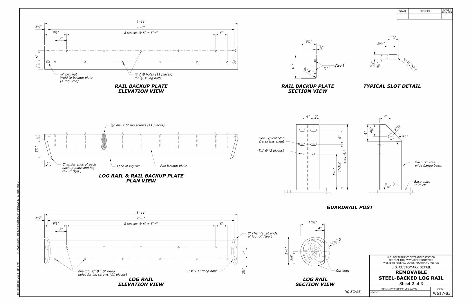
NO SCALE
(typ.)
ELEVATION VIEW
RAIL BACKUP PLATE
SECTION VIEW
RAIL BACKUP PLATE TYPICAL SLOT DETAIL
GUARDRAIL POST
PLAN VIEW
LOG RAIL & RAIL BACKUP PLATE
ELEVATION VIEW
LOG RAIL
SECTION VIEW
LOG RAIL
(4 required)
Weld to backup plate
backup plate and log
Chamfer ends of eachFace of log rail Rail backup plate
holes for lag screws (11 places)
of log rail (typ.)
Base plate
wide flange beam
Detail this sheet
See Typical Slot45°
(typ.)
Cut lines
WESTERN FEDERAL LANDS HIGHWAY DIVISION
DETAIL APPROVED FOR USE 3/2009
REVISED:
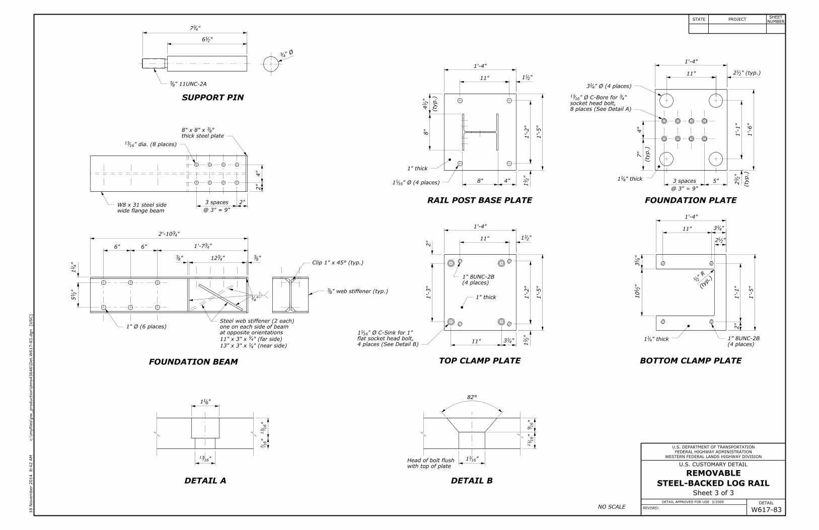
Sheet 3 of 3
STEEL-BACKED LOG RAIL
REMOVABLE
W617-83
2"
@ 3" = 9"
3 spaces
2"
4"
4"8"
" (typ.)212
2"
1'-1"
8:42 A
M
18 N
ove
mber 2
014
]U
SC
[
c:\m
yfiles\p
w_production\d
ms43646\Det.
W617-83.d
gn
FEDERAL HIGHWAY ADMINISTRATION
U.S. DEPARTMENT OF TRANSPORTATION
DETAIL
U.S. CUSTOMARY DETAIL
STATE PROJECTNUMBER
SHEET
1'-5"
1'-4"
"21111"
"2
11
1'-2"
(ty
p.)"
21
4
8"
1'-3"
2"
1'-4"
1'-5"
1" 8UNC-2B
"2
11
1'-2"
"21111"
"437
"216
" Ø4
3
"432'-10
"431'-76"6"
"83"4
312"83
"811
"1613
1'-5"
" R
21
1'-4"
11"
1'-6"
5"
@ 3" = 9"
3 spaces
4"
(ty
p.)
7"
1'-4"
(ty
p.)"
21
2
1'-1"
"41311"
"4
13
"2
110
" dia. (8 places)1613
"838" x 8" x
" 11UNC-2A85
W8 x 31 steel side
1" Ø (6 places)
" (near side)4113" x 3" x
" (far side) 41
11" x 3" x
" web stiffener (typ.)83
Clip 1" x 45° (typ.)
" Ø C-Sink for 1"1611
" Ø (4 places)1611
" Ø (4 places)413
"43" Ø C-Bore for 16
13
1" 8UNC-2B
"41
"1611
"16
11
"16
9
"4
11
"2
15 1" thick
" thick411
" thick411
1" thick
"41311"
"212
"16
7"
16
13
NO SCALE
82°
DETAIL A DETAIL B
BOTTOM CLAMP PLATETOP CLAMP PLATEFOUNDATION BEAM
RAIL POST BASE PLATE FOUNDATION PLATE
SUPPORT PIN
8 places (See Detail A)
socket head bolt,
thick steel plate
wide flange beam
at opposite orientations
one on each side of beam
Steel web stiffener (2 each)
4 places (See Detail B)
flat socket head bolt,
(4 places)
with top of plate
Head of bolt flush
(4 places)(typ.)
WESTERN FEDERAL LANDS HIGHWAY DIVISION
WM617-83
DETAIL APPROVED FOR USE 3/2009
REVISED:
Sheet 1 of 3
STEEL-BACKED LOG RAIL
REMOVABLE
2134
13 (typ.)
165
380 min.
75 clr.
690
350 O.C.
254
350 O.C.
13 (typ.)
(clr.)
100
25
610
4.
3.
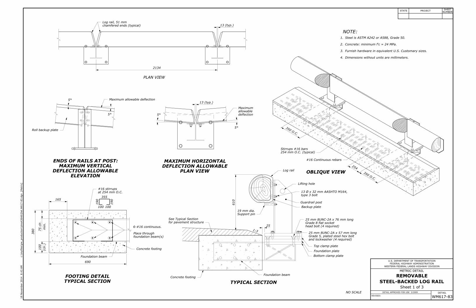
Dimensions without units are millimeters.
Furnish hardware in equivalent U.S. Customary sizes.
Concrete: minimum f'c = 24 MPa.
#16 Continuous rebars
254 mm O.C. (typical)
Stirrups #16 bars
25 mm 8UNC-2A x 76 mm long
25 mm 8UNC-2A x 57 mm long
19 mm dia.
6-#16 continuous.
at 254 mm O.C.
#16 stirrups
Log rail, 51 mm
355
190
100100
190
13 Ø x 32 mm AASHTO M164,
FEDERAL HIGHWAY ADMINISTRATION
U.S. DEPARTMENT OF TRANSPORTATION
METRIC DETAIL
DETAIL
]M
etric
[
c:\m
yfiles\p
w_production\d
ms43646\Det.
W617-83.d
gn
8:43 A
M
18 N
ove
mber 2
014
STATE PROJECTNUMBER
SHEET
NO SCALE
2.
1.
NOTE:
Steel is ASTM A242 or A588, Grade 50.
ELEVATION
DEFLECTION ALLOWABLE
MAXIMUM VERTICAL
ENDS OF RAILS AT POST:
PLAN VIEW
DEFLECTION ALLOWABLE
MAXIMUM HORIZONTAL
TYPICAL SECTION
FOOTING DETAIL
TYPICAL SECTION
OBLIQUE VIEW
chamfered ends (typical)
deflection
allowable
Maximum
Roll backup plate
for pavement structure
See Typical Section
Concrete footing
Foundation beam
Concrete footing
Support pin
Log rail
Lifting hole
type 3 bolt
Backup plate
and lockwasher (4 required)
Grade 5, plated steel hex bolt
Top clamp plate
Foundation plate
Bottom clamp plate
Foundation beam
PLAN VIEW
Guardrail post
1:3
head bolt (4 required)
Grade 8 flat socket
5°
5° 5°
5°
Maximum allowable deflection
foundation beam(s)
Place through

WESTERN FEDERAL LANDS HIGHWAY DIVISION
WM617-83
DETAIL APPROVED FOR USE 3/2009
REVISED:
Sheet 2 of 3
STEEL-BACKED LOG RAIL
REMOVABLE
127
2108
50
315
254
102
2108
127
9.5R
580
1278 spaces @ 203 = 1624242
203238
305
146
260
102
152
108
7 R (typ.)
R
14 7
171
9.5
76
127
1278 spaces @ 203 = 1624242
203238
54
27
401
127
51
210
51
102 51
67
127
318
W200 x 46 mm steel
25.4 mm thick10
6
17 Ø (2 places)
50 mm chamfer at ends
16 Ø x 127 mm lag screws (11 places)
for 15.9 Ø lag bolts
17.5 Ø holes (11 places)
rail 50 mm (typ.)
Pre-drill 9.5 Ø x 127 mm deep 51 Ø x 25 mm deep bore
13 mm hex nut
FEDERAL HIGHWAY ADMINISTRATION
U.S. DEPARTMENT OF TRANSPORTATION
METRIC DETAIL
DETAIL
]M
etric
[
c:\m
yfiles\p
w_production\d
ms43646\Det.
W617-83.d
gn
8:43 A
M
18 N
ove
mber 2
014
STATE PROJECTNUMBER
SHEET
NO SCALE
(typ.)
ELEVATION VIEW
RAIL BACKUP PLATE
SECTION VIEW
RAIL BACKUP PLATE TYPICAL SLOT DETAIL
GUARDRAIL POST
PLAN VIEW
LOG RAIL & RAIL BACKUP PLATE
ELEVATION VIEW
LOG RAIL
SECTION VIEW
LOG RAIL
(4 required)
Weld to backup plate
backup plate and log
Chamfer ends of eachFace of log rail Rail backup plate
holes for lag screws (11 places)
of log rail (typ.)
Base plate
wide flange beam
Detail this sheet
See Typical Slot45°
(typ.)
Cut lines
WESTERN FEDERAL LANDS HIGHWAY DIVISION
WM617-83
DETAIL APPROVED FOR USE 3/2009
REVISED:
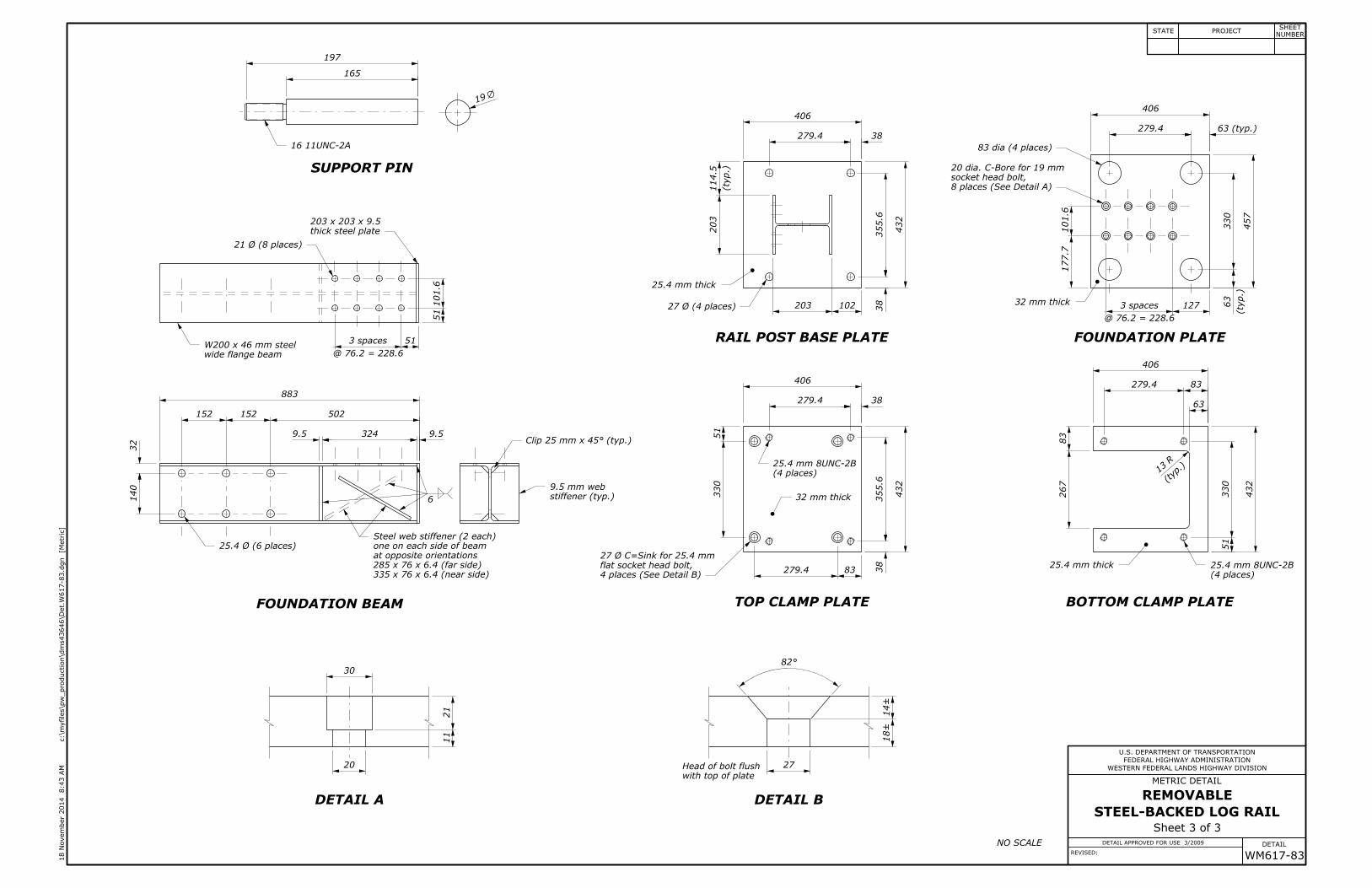
Sheet 3 of 3
STEEL-BACKED LOG RAIL
REMOVABLE
140
32
197
165
883
502152152
30
20 27
432
13
R
406
267
83
406
432
203 102
457
406
406
432
83279.4
83279.4
38279.4
38
355.6
9.53249.5
(ty
p.)
114.5
203
38279.4
38
355.6
63 (typ.)279.4
127
@ 76.2 = 228.6
3 spaces
101.6
177.7
18±
14±
11
21
51
101.6
51
330
19
63
330
(ty
p.)
63
51
330
51
@ 76.2 = 228.6
3 spaces
335 x 76 x 6.4 (near side)
285 x 76 x 6.4 (far side)
27 Ø C=Sink for 25.4 mm
Clip 25 mm x 45° (typ.)
6
203 x 203 x 9.5
21 Ø (8 places)
83 dia (4 places)
20 dia. C-Bore for 19 mm
25.4 mm 8UNC-2B
27 Ø (4 places)
25.4 mm 8UNC-2B
stiffener (typ.)
9.5 mm web
W200 x 46 mm steel
25.4 Ø (6 places)
16 11UNC-2A
FEDERAL HIGHWAY ADMINISTRATION
U.S. DEPARTMENT OF TRANSPORTATION
METRIC DETAIL
DETAIL
]M
etric
[
c:\m
yfiles\p
w_production\d
ms43646\Det.
W617-83.d
gn
8:43 A
M
18 N
ove
mber 2
014
STATE PROJECTNUMBER
SHEET
32 mm thick
25.4 mm thick
32 mm thick
25.4 mm thick
NO SCALE
82°
DETAIL A DETAIL B
BOTTOM CLAMP PLATETOP CLAMP PLATEFOUNDATION BEAM
RAIL POST BASE PLATE FOUNDATION PLATE
SUPPORT PIN
8 places (See Detail A)
socket head bolt,
thick steel plate
wide flange beam
at opposite orientations
one on each side of beam
Steel web stiffener (2 each)
4 places (See Detail B)
flat socket head bolt,
(4 places)
with top of plate
Head of bolt flush
(4 places)(typ.)