Embed Size (px)
Citation preview
' Reinforced Concrete : A n International Manual,
Written by a committee of experts commissioned by UNESCO
Translated by C. van Amerongen, M.Sc., M.I.C.E.
London Butterworths
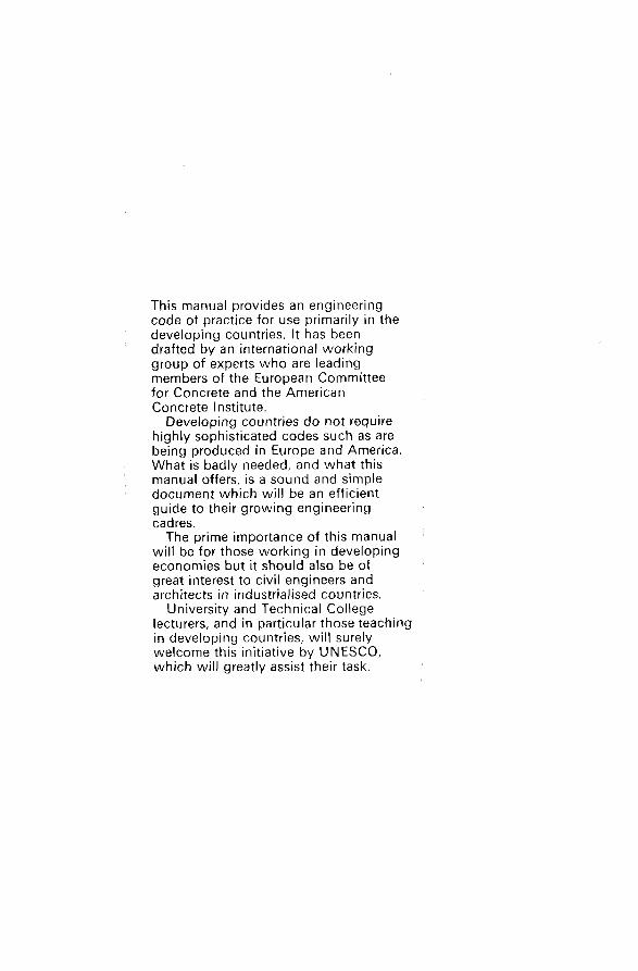
This manuai provides an engineering code of practice for use primarily in the developing countries. It has been drafted by an international working group of experts who are leading members of the European Committee for Concrete and the American Concrete Institute. Developing countries do not require
highly sophisticated codes such as are being produced in Europe and America. What is badly needed, and what this manual offers, is a sound and simple document which will be an efficient guide to their growing engineering cadres. The prime importance of this manual
will be for those working in developing economies but it should also be of great interest to civil engineers and architects in industrialised countries. University and Technical College
lecturers, and in particular those teaching in developing countries, will surely welcome this initiative by UNESCO, which will greatly assist their task.
,

Reinforced Concrete :
A n International Manual
Membership of the Committee Chairman Yves SAILLARD, Dr. Ing., Technical Director of the Chambre Syndicale Nationale des Constructeurs en Ciment Armé et Béton Précontraint de France, Secretary to the Permanent Comité Européen du Béton, 9, rue La Pérouse, Paris (le). Members Jean DESPEYROUX, Ing. Civil, Technical Director of the Société de Contrôle Technique et d’Expertise de la Construction, 4, rue du Colonel-Driant, Paris (1“). A. M. HAAS, Prof. Dr. Ing., Department of Civil Engineering, Technological University Delft, 25, Oostplantsoen, Delft (Holland). Telemaco VAN LANGENDONCK, Prof. Dr. Ing., Escola Politecnica de Universidade de Sao-Paulo, Caixa Postal, 30086, Sao-Paulo (Brazil). Franco LEVI, Prof. Dr. Ing., Istituto Universitario di Architettura di Venezia, Chairman of the Comité Européen du Béton and of the Fédération Internationale de la Précontrainte, Corso Casale, 182, Turin (Italy). Alan H. MATTOCK, Prof. Dr. Ing., Department of Civil En- gineering, University of Washington, Seattle, Washington, 98105 (U.S.A.). Jacques NASSER, Prof. Dr. Ing., Université Américaine de Beyrouth, B.P. 2660, Beyrouth (Lebanon). André PADUART, Prof. Dr. Ing., Université Libre de Bruxelles, 49, square des Latins, Bruxelles-5 (Belgium). Raymond C. REESE, Consultant Engineer, Past President of the American Concrete Institute, Member of the Committee ACI-318 “Standard Building Code”, 743, South Byrne Road, Toledo, Ohio 43609 (U.S.A.). Stefan SORETZ, Dr. Ing., Consultant Engineer, Klopsteinplatz, 1, A. 1030, Vienna (Austria).
Secretary Stéphane BERNAERT, MSc. (Illinois, U.S.A.), Ing. Civil, Pro- fessor at the Ecole Spéciale des Travaux Publics, Paris, 9, rue La Pérouse, Paris (le).
THE BUTTERWORTH GROUP
ENGLAND Buttenvorth & C o (Publishers) Ltd London : 88 Kingsway. W C 2 B 6 A B
Butterworth & C o (Australia) Ltd Sydney: 586 Pacific Highway, Chatswood, N S W 2067 Melbourne: 343 Little Collins Street, 3000 Brisbane: 240 Queen Street, 4000
Buttenvorth & C o (Canada) Ltd Toronto: 14 Curity Avenue, 374
Butterworth & C o (New Zealand) Ltd Wellington: 26-28 Waring Taylor Street, 1 Auckland: 35 High Street, 1
Buttenvorth & Co (South Africa) (Pty) Ltd Durban: 152-154 Gale Street
First published in 1971 0 Unesco 1967 English translation 0 Unesco 1971 ISBN O 408 70175 7
Filmset by Photoprint Plates Ltd, Rayleigh, Essex
Printed in England by Camelot Press Ltd. Southampton
A U S T R A L I A
CANADA
NEW ZEALAND
S O U T H AFRICA
PREFACE
In support of a number of technical assistance projects in developing countries Unesco is carrying out extensive studies in fields where activities appear to be most promising for the transfer of technologies to the developing countries, for example in standardisation, engineering codes of practic,e, and guides for the design and construction, or manufacture, of engineering works. The absence of such standards, guides and recommendations may seriously
hamper economic progress. Foreign standards and codes are often used although they may not be the most suitable owing to climatic conditions, or the stage of economic and social development of the country concerned. The drafting and development of the principal standards and codes is a matter of great urgency and of prime importance to the economic progress of developing countries. There is an immense body of knowledge available in the industrial
countries in the field of standards and engineering codes, but in order to apply this knowledge in developing countries, the available material must be judiciously selected, sifted and modified by experienced engineers and research workers, in cooperation with the international engineering associa- tions and organizations for standardisation. This activity is an outstanding example of technical assistance where existing knowledge can be applied to development efficiently and with the least delay. The developing countries do not require highly sophisticated codes, such
as are being produced in Europe and America. However, what is badly needed is a sound and simple document which will be an efficient guide to their growing engineering cadres. This manual is one of the first attempts at providing an engineering code
for use in the developing countries. Reinforced Concrete: A n International Manual has been drafted by an International Working Group consisting of: Y. Saillard (France), Chairman, J. Despeyroux (France), A. M. Haas (Holland), T. van Langendonck (Brazil), F. Levi (Italy), A. H. Mattock (U.S.A.), J. Nasser (Lebanon), A. Paduart (Belgium), R. C. Reese (U.S.A.), S. Soretz (Austria), S. Bernaert, Secretary. Unesco wishes to express its appreciation

and gratitude to all Members of the Group for their excellent work which they have carried out with great expertise, efficiency and dispatch. The document has been discussed extensively by this group of experts
who are some of the leading members of the European Committee for Concrete and of the American Concrete Institute.
CONTENTS
PART 1
Chapter 1 Scope And Object Of The Design Calculations 1.1 Scope 1.2 Object Of The Design Calculations
Chapter 2 Units And Notation 2.1 Units 2.2 Notation
Chapter 3 Determination Of The Properties Of The Materials 3.1 Steel 3.2 Concrete
Chapter 4 Determination Of Safety 4.1 Principle Of Checking The Safety 4.2 Determination Of The Characteristic Loadings 4.3 Determination Of The Basic Strengths
1
3
16
24
Chapter 5 Determination Of The Effects Of The Permanent Loads, 29 Superimposed Loads And Other Actions 5.1 Structures Composed Of Linear Members 5.2 Plane Structures
Chapter 6 Determination Of Sections 6.1 Normal Forces And Stresses 6.2 Tangential Actions And Stresses
Chapter 7 Constructional Arrangements 7.1 Agreement Between Constructional Arrangements And
Design Assumptions
39
102
7.2 General Conditions Relating To The Reinforcement 7.3 Arrangements Peculiar To Various Structural Members
Chapter 8 Preparation Of Designs 8.1 Calculations 8.2 Drawings 8.3 Conditions Of Execution
Chapter 9 Execution Of Structures 9.1 Requirements Pertaining To Formwork 9.2 Matters Pertaining To Reinforcement 9.3 Requirements Pertaining To Concrete 9.4 Tolerances
Chapter 1
Chapter 2
Chapter 3
Chapter 4
124
128
PART 2
Usual Values Of Superimposed Loads And Wind Actions 1.1 Preamble 1.2 Definitions 1.3 Variable Superimposed Working Loads 1.4 Wind Effects
181
Determination Of Safety O n The Basis Of Probability 2.1 Preliminary Considerations 2.2 The Principles Of The Probability Theories Of Safety 2.3 C.E.B./C.I.B. Semi-probability Design Method 2.4 Characteristic Values And Design Values Of The Permanent
Loads, Superimposed Loads And Other Actions 2.5 Characteristic Strengths And Design Strengths Of Steel
And Concrete 2.6 Method Of Checking The Safety 2.7 Relation Between The C.E.B./C.I.B. Semi-Probability
198
Method And The UNESCO Simplified Method
Uniaxial Bending -Theoretical Analysis 21 1 3.1 Recapitulation Of The Fundamental Design Assumptions 3.2 Analysis Of A Symmetrical Section Of Arbitrary Shape 3.3 Analysis Of A Rectangular Section
Uniaxial Bending- Practical Design Calculations 4.1 Preamble 4.2 Properties Of The Materials 4.3 Simple Uniaxial Bending 4.4 Composite Uniaxial Bending With Compression 4.5 Composite Uniaxial Bending With Tension
231
Chapter 5 Analysis Of Tensile And Flexural Cracking 285 5.1 Preliminary Remarks 5.2 Analysis Of Cracking In Reinforced Concrete 5.3 Practical Checking Of Cracking In Reinforced Concrete
Chapter 6 Calculation Of Flexural Deformations 311 6.1 Recapitulation Of The Fundamental Assumptions For The
Calculation Of Deformations 6.2 Determination Of The Basic Steel And Concrete Strains 6.3 General Calculation Oi Deflection Curves And Deflections 6.4 Simplified Calculation For Ordinary Buildings
Chapter 7 Shrinkage And Creep Of Concrete 7.1 Shrinkage 7.2 Creep
320
Chapter 8 Design Of Slabs And Plane Structures 329 8.1 Subject And Field Of Application 8.2 Ultimate Limit State Corresponding To Failure By Exhaus-
8.3 Yield Line Theory 8.4 Practical Design Formulae For Simple Slabs 8.5 Practical Design Formulae For Flat-Slab Floors And
tion Of The Flexural Capacity (Flexural Failure)
Mushroom Floors

Part 1
1
SCOPE AND OBJECT OF THE DESIGN CALCULATIONS
1.1 SCOPE
The Manual applies to all reinforced concrete structures with the exception of structures which are to be exposed to temperatures above 70°C and struc- tures for which special design rules are necessary, namely:
(a) lightweight concrete structures; (b) prestressed concrete structures; (c) composite structures comprising reinforced concrete and structural
(d) concrete structures reinforced with rolled steel joists.
For residential buildings which are not exceptional in character and which comprise not more than five storeys (i.e., four upper floors) the building owner may authorise the designer to employ a simplified design method, e.g., a method based on the use of the modular ratio, provided that the overall safety of the structure and the safety of each of its component members are checked to ensure that, in all circumstances and for any combinations of loads, superimposed loads and other actions, they are at least equal to the structural safety that can be obtained by rigorous application of the code of practice detailed in this Manual.
steelwork;
1.2 OBJECT OF THE DESIGN CALCULATIONS
1.2.1 NOTION OF ‘UNFITNESS’
All reinforced concrete structures or structural members should be so designed and constructed that they are able, with appropriate safety, to withstand all the loads, superimposed loads and other actions liable to occur during construction and in use.
2 The object of the design calculations is to guarantee sufficient safety
against the structure being rendered ‘unfit for service.’ A structure is considered to have become ‘unfit’ when one or more of its
members ceases to perform the function for which it was designed, owing to failure, buckling due to elastic, plastic or dynamic instability, excessive cracking, excessive elastic or plastic deformation, etc.
1.2.2 NOTION OF ‘LIMIT STATE’
To each of the conditions in which a structure becomes ‘unfit for service’ corresponds a particular state called a ‘limit state’. These limit states are respectively : (a) the ultimate limit state (failure); (b) the limit state of instability; (c) the limit state of cracking; (d) the limit state of deformation; etc. The basic idea of the design method embodied in this Manual is to con-
sider each limit state respectively and to check that, for each of these limit states, all the members of the structure as well as the structure as a whole are able, with appropriate safety for each of them, to withstand all the loads, super- imposed loads and other actions liable to occur during construction and in use.
1.2.3 GENERAL DESIGN PROCEDURE
The design method embodied in this Manual comprises the following successive stages:
determination of the safety for each condition in which the structure becomes unfit, i.e., for each limit state;
determination of the effects of the loads, superimposed loads and other actions, i.e., determination of the internal forces for the structure as a whole and for each of its members;
dimensional design of the sections for each limit state.
2
UNITS AND NOTATION
2.1 UNITS
The system of measurement and units is the decimal metric system with six basic units, as adopted by the General Conference on Weights and Mea- sures and known as the ‘International S.I. System’. However, under the code of practice of this Manual it will be permissible
to use the ‘metre/kilogramme-force/second’ system on an interim basis.
2.1.1 BASIC UNITS
The six basic units of the ‘International S.I. System’ are: the metre (m) the kilogramme (kg) the second (s) the ampere (A) the degree Kelvin (K) the candela (cd)
unit of length: unit of mass : unit of time : unit of electric current intensity: unit of temperature: unit of light intensity:
2.1.2 SECONDARY UNITS
Of the secondary units the following more particularly concern reinforced concrete design.
The unit offorce is the newton (N), this being the force which imparts to a mass of one kilogramme an acceleration of one metre per second per second.
The unit of work and energy is the joule (J), this being the work done by a force of one newton whose point of application is displaced a distance of one metre in the direction of the force.
1 J = 1 N.m The unit of pressure and stress is the pascal (Pa), this being the uniform
3
4 pressure which, acting upon a plane surface of one square metre, exerts a total force of one newton perpendicularly to that surface.
1 Pa = 1 N/m2 A unit associated with the pascal is the bar, which is equal to 1 bar = Pa = N/m2.
pascal:
2.1.3. RELATIONS BETWEEN THE S.I. UNITS A N D THE UNITS OF THE ‘METRE/KILOGRAMME-FORCE/ SECOND’ SYSTEM
A kilogramme-force (or kilogramme-weight) is equal to about 9.8 newtons (9.8 N) or 0.98 decanewton (0.98 daN):
1 kgf = 9.8 N = 0.98 daN, and conversely: 1 daN = 10 N = 1.02 kgf. A decanewton therefore corresponds within 2 % to a kilogramme-force. A kilogramme-force (or kilogramme-weight) per square centimetre is
1 kgf/cm2 = 0.98 bar and conversely: 1 bar = 1.02 kgf/cm2.
equal to 0.98 bar:
2.2 NOTATION
The notation uses Roman capitals and small letters, as well as small Greek letters, with or without the addition of indices or subscripts. The use of Greek capitals is not recommended. O n the other hand, the
use of small Greek letters is considered to Fit in with the tradition of standard text-books on strength of materials and theory of structures and to be compatible with the possibilities of present-day typewriters.
2.2.1 SMALL R O M A N LETTERS
These denote: lengths, forces and moments per unit length, and external forces distributed per unit area.
2.2.2 R O M A N CAPITALS
These denote: geometrical and mechanical properties of the cross-sections of prismatic members (areas, static moments, moments of inertia, section moduli, applied external forces (total distributed forces or concentrated forces) and their moments, and longitudinal strain moduli of materials.
2.2.3 SMALL GREEK LETTERS
These denote: stresses, strains, angles and slopes, and dimensionless co- efficients.
5 2.2.4 INDICES
Compression is distinguished from tension by the addition of the prime (’) to denote compression. The symbols for characteristic loadings and basic strengths to which the
analysis and design calculations relate are provided with a bar (-) over the top. In practice, however, the prime and the bar may be omitted in all cases
where there is no possibility of error of interpretation. More particularly, there is no need to usc the prime when tension and compression are dis- tinguished by the algebraic sign of their numerical value in the calculation:
+ for tension; - for compression.
2.2.5 SUBSCRIPTS
The following subscripts are used: a -to denote the steel; b -to denote the concrete; c -to denote the critical state of buckling; d -to denote the bond between concrete and steel; e -to denote the (apparent or conventional) elastic limit of the steel; m - to denote mean values; r -to denote the failure characteristics of steel and concrete; u -to denote the ultimate limit state (limit state of failure) of a reinforced
Wherever there is no ambiguity the use of multiple subscripts should be concrete member.
avoided.
2.2.6 PERMITTED EXCEPTIONS
The code of practice in this Manual allows some exceptions. These concern the use of the following symbols, sanctioned by usage in the majority of countries: (a) diameter represented by 4 (instead of a small Roman letter); (b) crack spacing represented by Al (instead of a single small Roman letter); (c) modular ratio (ratio of the moduli of elasticity of steel and concrete)
represented by m or n (instead of a small Greek letter).
2.3 MAIN NOTATION USED IN THE CODE AND THE MANUAL
2.3.1 R O M A N CAPITALS
A = cross-sectional area of reinforcement A = cross-sectional area of main tensile reinforcement
6 A, = cross-sectional area of each individual layer of connector reinforce-
A’ = cross-sectional area of main compressive reinforcement
B = cross-sectional area of concrete; more particularly : cross-sectional area of concrete in tension
B’ = cross-sectional area of concrete in compression Bi = cross-sectional area of the core of a member with binding reinforce-
ment (or transverse reinforcement)
B = cross-sectional area of concrete
ment C = cement content C = cement content (weight of cement used in making one cubic metre of
concrete) E = strain modulus of a material (or more specifically: modulus of elasticity) E, = longitudinal strain modulus (modulus of elasticity) of steel íexcep-
Eb = longitudinal strain modulus of concrete Ebo = longitudinal strain modulus of concrete for instantaneous (or
EA, = longitudinal strain modulus of concrete for long-term (sustained)
tion in common use)
rapidly variable) loads
loads F = load acting in any direction G = permanent load, dead load G, = characteristic value of a permanent load in the general case G, = mean (or average) value of a permanent load in the general case GL = characteristic value of a permanent load in the particular case
where a decrease in this load could endanger the stability of the structure
Ck = mean (or average) value of a permanent load in the particular case where a decrease in this load could endanger the stability of the structure
other meaning: gravel content G = gravel content (weight of gravel used in making one cubic metre of
concrete as placed) H = horizontal reaction I = moment of inertia (second moment of area) of a section I, = moment of inertia of a section about any reference axis O, I, = moment of inertia of a section about a reference axis U, perpendicular
I, = moment of inertia of a homogeneous section (uncracked: ‘state i’)
A4 = bendingmoment M, = bending moment when the first cracks appear (‘state I’) M,, = difference between the total bending moment M and the partial
to o,
M = bending moment
bending moment A41
7 M, = additional moment, used in analysing the buckling of a com-
M,, = additional moment, in the principal direction x, in analysing the
M,, = additional moment, in the principal direction y, in analysing the
M, = upper limit value adopted for bending moment in failure analysis Mu = bending moment at failure (ultimate moment)
N = normal force (generic term) N, = resultant tensile force in main tensile reinforcement Nb = resultant compressive force in concrete N; = component of normal compressive force, in principal direction x,
Ni, = component of normal compressive force, in principal direction y,
Nu = normal force at failure íultimate state)
pression member
buckling of a plate
buckling of a plate
N = normal (or direct) force
for a plate loaded parallel to its middle plane
for a plate loaded parallel to its middle plane
P = vertical load Q = superimposed load, live load íthe symbol is also used to denote a loading
of random character) Qk = characteristic value of a superimposed load (or of a loading other-
wise imposed) in the general case Q;, = characteristic value of a superimposed load in the particular case
where a reduction of this load could endanger the stability of the structure
Q, = most unfavourable value of the superimposed load (or loading otherwise imposed) with 50 % probability of being exceeded (in the direction of abnormally high values) once during the anticipated service life of the structure
Q; = most unfavourable value of the superimposed load (or loading otherwise imposed) with 50% probability of being exceeded (in the direction of abnormally low values) once during the anticipated service life of the structure
Q* = design value of superimposed load (or loading otherwise imposed) las conceived in the CIB/CEB semi-probabilistic method)
R = bearing reaction, reaction at support R = bearing reaction in any particular direction
S, = characteristic loading corresponding to the permanent loads S,, = characteristic loading corresponding to the variable superimposed
S,, = characteristic loading corresponding to the dynamic superimposed
S, = characteristic loading corresponding to the effects of shrinkage,
S = loading íin the most general sense)
working loads
working loads
creep and temperature variations
8 S, = characteristic loading corresponding to superimposed loads from
wind, snow and seismic effects other meaning: static moment, first moment of area of a section S = static moment of a section S, = static moment of a section about any reference axis O,
T = shear force (generic term) T, = contribution of the transverse reinforcement to the shear strength
& = contribution of the concrete in the compressive zone to the shear T, = shear force at failure (ultimate state)
T = shear force
(Morsch’s term)
strength
other meaning: overturning force
other meaning (exception in common use): temperature U = lifting force
I/ = vertical reaction other meaning (exception in common use): volume V = volume of an aggregate particle
other meaning (exception in common use): velocity
V = wind velocity W = section modulus
T = overturning force exerted on a structure by wind
U = centrally acting lifting force exerted on a structure by wind
2.3.2 R O M A N SMALL LETTERS
a = transverse dimension of a concrete section, or of a mesh in a grid or
a = transverse dimension of a concrete section (in most cases ‘a’ denotes
a = edge length of a test cube a = larger side of the area of application of a concentrated load a = larger side of a mesh in welded fabric reinforcement
lattice, or (more generally) of a side of a rectangle
the largest transverse dimension)
b = transverse dimension of a concrete section, or of a mesh in a grid or
b = transverse dimension of a concrete section (in most cases ‘b‘ denotes
b = side of square section b = width of the section of a rectangular beam, floor slab or compression
flange of a T-beam b = smaller side of the area of application of a concentrated load
lattice, or (more generally) of a side of a rectangle
the smallest transverse dimension)
9 b = smaller side of a mesh in welded fabric reinforcement b, = effective width of the compression flange of a T-beam b, = fictitious width of the rectangular section equivalent to a section of
bo = width of the web (or rib) of a T-beam at the level of the median axis b,, = width of the binders (or links) forming the transverse reinforcement
in a member subjected to torsion bo = thickness of the wall of a hollow member b, = width of a haunch or splay or chamfer b, = fictitious design width of the rib of a T-beam provided with chamfers b‘ = width of the tension flange (or enlarged bottom of web) of a T-beam
c = concrete cover to steel c,, = horizontal cover c, = vertical cover
d = distance from centroid of main tensile reinforcement to the extreme fibre in greatest tension or least compression; or: distance from centroid of a tensile reinforcing bar to the nearest concrete face
d’ = distance from centroid of main compressive reinforcement to the
any shape
d = distance
’ (calculation of anchorage length)
extreme fibre in greatest compression other meaning : diameter of a circular section
other meaning: dimension of aggregate particles
d, = mean for average) diameter or fictitious thickness of a member
do and d,, = minimum and maximum dimensions characterising the class of an aggregate
e = eccentricity of a normal (or direct) force e = eccentricity of the normal force e, = design value of initial eccentricity of the normal force e, = design value of additional eccentricity of the normal force
other meaning: distance
e = distance from centre of curvature of an anchorage based on curvature to the nearest concrete face
e, = distance from centre of curvature of a curved bar to the concrete face situated on the side to which the ‘radial’ force (due to the curva- ture) is directed (unbalanced thrust)
f = deflection f, = total instantaneous deflection f, = total long-term deflection fi = partial deflection attained before cracking develops (‘state I’) fir = partial deflection which occurs after cracking develops (‘state II’) flI = limit value of the total deflection (‘state II’) ho = depth of a slab or of the compression flange of a T-section h, = depth of a haunch or splay or chamfer
h = depth (or height)
10 h, = total geometric depth of the cross-section of a beam (or total thick-
h' = distance between the centroids of the main reinforcements h" = distance from centroid of compressive reinforcement (or reinforce-
ment in greatest compression) to the tensile fibre (or the fibre in least compression)
h,, = depth (or height) of the binders (or links) forming the transverse reinforcement in a member subjected to torsion
h = difference in level between the base of a structure and the ridge of the roof (for determining effects of wind)
ness of a slab or a plate)
i = radius of gyration i, = radius of gyration of a section about the principal axis normal to the
i, = radius of gyration of a section about any reference axis x plane of bending
k: see K 1 = length
I = clear span of a beam 1 = clear length of a structural member 1, = effective length (with regard to buckling) of a structural member 1, = straight bond length in tension 1, = straight bond length in compression 1, = effective bond length m = bending moment per unit width of slab mi = resisting moment per unit width of slab, corresponding to reinforcing
bars parallel to the direction i Note: if it is necessary to indicate the sign of the moment, the addition of a prime (mi) denotes a negative moment
rn, = normal bending moment acting at a yield line per unit length of that line
m, = torsional moment acting at a yield line per unit length of that line m, and m,, = principal bending moments per unit width of slab at a
particular point of the slab other meaning: modular ratio in conventional reinforced concrete design (exception in common use) (the symbol n is also used to designate the modular ratio)
n = modular ratio in conventional reinforced concrete design (exception in common use) (the symbol m is also used to designate the modular ratio)
other meaning: number or quantity (exception in common use) n = number of bars making up the reinforcement n = number of rigid elements into which a slab is divided by yield lines
p = perimeter of the cross-section of a reinforcing bar or group of bars p' = perimeter of the critical area in the analysis of a slab for punching
p = perimeter
shear q = superimposed distributed load per unit area or unit length
1 1 r = radius
r = radius of a circular section Y = radius of curvature of a structural element r = radius of curvature of the axis of a bar
s = tangential force per unit of developed length of the wall of a torsionally s = tangential force per unit area
loaded member other meaning: standard deviation t = spacing of connector reinforcement
other meaning: (exception in common use) time
u = distance to centroid of a section
t = spacing of two consecutive layers of connector reinforcement
At = interval of time
u = distance from the extreme fibre in greatest tension (or least com-
u’ = distance from the fibre in greatest compression to centroid of section w = width of a crack
x = distance from neutral axis to the face in greatest compression of a
xi = ordinate of any particular fibre in the section of a member subjected
pression) to centroid of section
w = width of a crack
x = co-ordinate
member subjected to bending
to bending, with reference to the neutral fibre of that member y = co-ordinate y = depth of the rectangular diagram used in the simplified flexural
design method z = lever arm z = lever arm of the internal forces which form a couple to resist the
bending moment
2.3.3 GREEK CAPITALS
A = change in quantity, interval (exception in common use) AZ = crack spacing (distance between two consecutive cracks) At = interval of time
= elastic strain of concrete produced by changes in the intensity of the applied load
2.3.4 GREEK SMALL LETTERS
ci = coefficient ci = coefficient of thermal expansion
12 CI = coefficient to take account of dynamic increases in the superimposed
working loads M, = coefficient representing effect of thickness of a member on creep of
concrete CI, = coefficient representing effect of thickness of a member on shrinkage
of concrete (also other uses as a coefficient, more particularly in 6.2.4 and 9.4.2 of Part 1)
other meaning: angle
CI = angle of inclination of connector reinforcement with respect to the plane on which the tangential action is exerted, or: angle of inclination of transverse reinforcement with respect to centre-line of member
CI = inclination of a roof (angle with respect to the horizontal)
fl = coefficient representing effect of load arrangement (calculation of ß, = coefficient representing effect of concrete composition on creep ß, = coefficient representing effect of concrete composition on shrinkage ß = ratio between external normal force and normal resisting force
developed by the concrete section of a column (calculation of minimum reinforcement percentage) (also other uses as a coefficient, more particularly in 6.2.4 of Part i)
ß = coefficient
deflections)
y = factor of safety Y YWI
ysteei yconcrete = reduction coefficient for the strength of concrete Y S
= overall factor of safety = reduction coefficient for the strength of a material = reduction coefficient for the strength of steel
= amplification coefficient for a loading or its effects 6 = relative mean square deviation (coefficient or variation) E = strain of a material
E, = tensile strain of steel E, = tensile strain of steel corresponding to the beginning of yielding E: = compressive strain of steel &b = tensile strain of concrete E; = compressive strain of concrete EO = maximum compressive strain of concrete AE;
Ebi &gm &br
E;, or E: = instantaneous elastic compressive strain of concrete = variation of the elastic compressive strain of concrete caused by
= instantaneous plastic compressive strain of concrete = long-term plastic compressive strain of concrete = creep of concrete (final creep coefficient) = shrinkage of concrete (final shrinkage coefficient)
a variation in load intensity
c = coefficient = coefficient representing influence of age at loading on creep of con-
crete
13 8 = relative shear force
other meaning: angle of rotation
IC = coefficient
f the expression ‘reduced shear force’ is alternatively used)
û = angle at centre of curvature of a bent bar
IC = coefficient applicable to the coefficient of variation and depending on the probability, accepted a priori, of obtaining test results which fall short of the characteristic strength or of having a loading which exceeds the characteristic value of the loading
IC, = regional coefficient (determination of wind effects) IC, = site coefficient (determination of wind effects)
R = slenderness ratio of a structural member fR = l/i) ,u = relative bending moment
other meaning: percentage of openings
íthe expression ‘reduced bending moment’ is alternatively used)
,u = percentage of the area of openings in the total wall area of a building (determination of wind effects)
v = relative normal force
other meaning : Poisson’s ratio
other meaning: percentage of cement paste in concrete (exception in common use; per- centages are otherwise generally designated by the symbol w)
other meaning: coefficient characterising wind actions
íthe expression ‘reduced normal force’ is alternatively used)
v = Poisson’s ratio
v E + c = percentage of cement paste in concrete
v o = coefficient characterising external wind actions on a structure v 1 = coefficient characterising internal wind actions on a structure
n: = the number 3.1416 ... . w = percentage w wp = mechanical percentage of longitudinal tensile reinforcement strictly
necessary for resisting the fictitious moment M + 1.5 1 TI -0.5 I N’ I (shear analysis)
= mechanical percentage of longitudinal tensile reinforcement
wo = geometric percentage of longitudinal tensile reinforcement wlo = geometric percentage of the ‘tie-bars’ in a member loaded in torsion a, = mechanical percentage of connector reinforcement (or transverse wlo = geometric percentage of connector reinforcement lor transverse
reinforcement)
reinforcement), or : geometric percentage of the binders forming the transverse rein- forcement in a member loaded in torsion
w’ = mechanical percentage of longitudinal compressive reinforcement
14 ab = geometric percentage of longitudinal compressive reinforcement ai = geometric percentage of transverse binding reinforcement
other meaning: specific gravity p = coefficient
pt = coefficient representing the influence of time on the shrinkage and creep of concrete
o = normal (or direct) stress; where necessary, a prime (’) may be added to the symbol in order to denote compressive stress
om = mean strength of a material ok = characteristic strength of a material o* = design strength of a material (CEB/CIB semi-probabilistic method) o, = tensile stress in steel o, = yield point (apparent elastic limit) for ordinary reinforcing steel oo.2 = 0.2 % proof stress (conventional elastic limit) for cold-worked oOm = mean tensile strength (elastic limit) of steel oak = characteristic tensile strength (elastic limit) of steel o,* = design tensile strength (elastic limit) of steel íCEB/CIB semi-
o, = basic tensile strength of steel (UNESCO simplified method) o: = compressive stress in steel o:* = design compressive strength (elastic limit) of steel (CEB/CIB
3, = compressive steel stress to be used in analysing the ultimate
ot = basic strength of transverse reinforcing steel (UNESCO simplified
ob = tensile stress in concrete o. = tensile strength of concrete at age of 28 days oj = tensile strength of concrete at age ofj days obm = mean tensile strength of concrete obk = characteristic tensile strength of concrete o: = design tensile strength of concrete íCT.B/CIB semi-probabilistic
ob = basic tensile strength of concrete (UNESCO simplified method) o; = compressive stress in concrete ob = compressive strength of concrete at age of 28 days o: = compressive strength of concrete at age of j days ob, = mean compressive strength of concrete oLk = characteristic compressive strength of concrete o;* = design compressive strength of concrete íCEB/CIB semi-probabi-
o; = basic compressive strength of concrete (UNESCO simplified
obo = limit strength of concrete in a member under uniaxial compression
reinforcing steel
probabilistic method) -
semi-probabilistic method)
strength of a section (UNESCO simplified method)
method)
-
method) -
listic method)
method)
(UNESCO simplified method)
15 o; oEx = Euler stress, in the principal direction x, in a plate a;, = Euler stress, in the principal direction y, in a plate o1 = largest extreme stress in a multiple state of stress o2 = smallest extreme stress in a multiple state of stress o3 = intermediate stress in a multiple state of stress
z,, = bond stress between concrete and steel rd = limit value of anchorage bond stress zdl = limit value of flexural bond stress
$ = basic creep coefficient I) = coefficient of friction between steel and concrete I) = a quantity occurring in the expression for the maximum diameter of
= Euler stress in a strut or column (buckling analysis)
z = tangential stress (or shear stress)
I) = coefficient
reinforcing bars (analysis of cracking) 4 = diameter of reinforcing bar I)ij or c # ~ ~ ~ = angle formed by the yield lines i and j in a slab
3
DETERMINATION OF THE PROPERTIES OF THE MATERIALS
3.1 STEEL
3.1.1 DEFINITION OF THE REINFORCING BARS USED
The reinforcing bars used are classified into four categories : plain bars, deformed bars, welded fabric, rolled steel sections.
Plain bars are generally rolled from mild steel or from medium-tensile steel.
Deformed bars (developing high bond strength in virtue of projections or indentations) are generally rolled to a special geometrical profile; they are of medium-tensile (or sometimes high-tensile) steel whose properties are obtained either by appropriate composition (ordinary steels) or by cold- working involving twisting or cold-drawing (cold-worked steels). Guarantees must be given for these bars, more particularly with regard
to the geometrical and mechanical properties to be adopted in the design calculation. These guarantees should be furnished by the manufacturers and be checked by the representative of the building owner.
Fabric reinforcement generally consists of medium-tensile drawn steel wires. It requires guarantees similar to those giveii for deformed reinforcing bars.
Structural rolled steel sections can permissibly be used as reinforcement subject to special justifications; the same applies to composite flexural members having the tensile flange and the web made of steel, while the compressive flange is of concrete. In the absence of regulations applicable to this type of construction, the necessary justifications may consist of experimental checks, comprising loading tests to failure, according to a procedure agreed with the building owner.
16
17 3.1.2 DEFINITION OF BAR DIAMETERS USED
The following bar diameters, expressed in millimetres, may be used : 4 5, 4 6, 4 8, 4 10, 4 12, 4 16, 4 20, 4 25, 4 32, 4 40 The ten diameters indicated, forming a series serving as the basis for the
standardisation of reinforcing bars, have the important advantage that they can be distinguished from one another by visual inspection on the site. Besides, the cross-sectional area corresponding to each diameter is approxi- mately equivalent to the sum of the cross-sectional areas of the two preceding bar sizes. This facilitates all combinations. Five other diameters (4 14, q5 18, 4 22, 4 28, 4 30) are permitted, but it is
strongly recommended not to use them, so as to avoid any possible confusion with the next larger or smaller bar sizes on the site.
3.1.3 MECHANICAL REFERENCE PROPERTIES OF THE STEEL
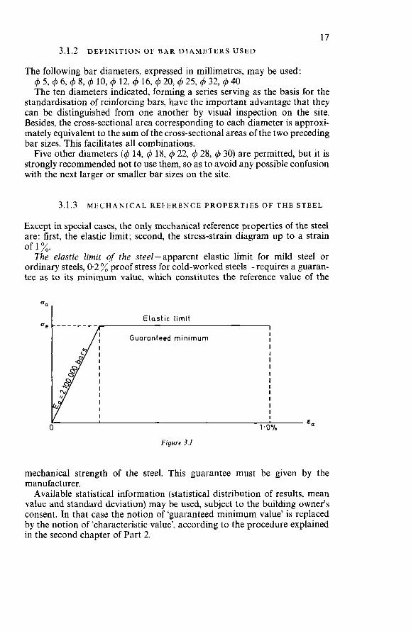
Except in special cases, the only mechanical reference properties of the steel are: first, the elastic limit; second, the stress-strain diagram up to a strain
The elastic limit of the steel-apparent elastic limit for mild steel or ordinary steels, 0.2 % proof stress for cold-worked steels -requires a guaran- tee as to its minimum value, which constitutes the reference value of the
of 1 %.
I
I I
I
I
I I
B I CL
4/ 1: Guaranteed minimum
Figure 3.1
mechanical strength of the steel. This guarantee must be given by the manufacturer. Available statistical information (statistical distribution of results, mean
value and standard deviation) may be used, subject to the building owner’s consent. In that case the notion of ‘guaranteed minimum value’ is replaced by the notion of ‘characteristic value’, according to the procedure explained in the second chapter of Part 2.
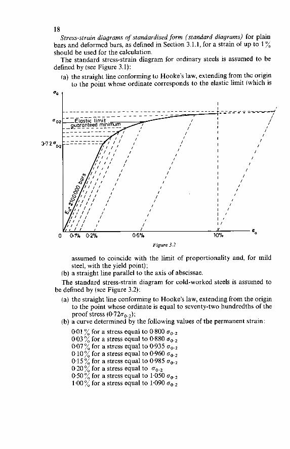
18 Stress-strain diagrams of standardised form (standard diagrams) for plain
bars and deformed bars, as defined in Section 3.1.1, for a strain of up to 1 % should be used for the calculation. The standard stress-strain diagram for ordinary steels is assumed to be
defined by (see Figure 3.1): (a) the straight line conforming to Hooke's law, extending from the origin
to the point whose ordinate corresponds to the elastic limit (which is
I
Figure 3.2
assumed to coincide with the limit of proportionality and, for mild steel, with the yield point);
(b) a straight line parallel to the axis of abscissae. The standard stress-strain diagram for cold-worked steels is assumed to
(a) the straight line conforming to Hooke's law, extending from the origin to the point whose ordinate is equal to seventy-two hundredths of the proof stress (0.7200.,);
0.01 % for a stress equal to 0.800 go., 0.03 % for a stress equal to 0.880 oO., 0.07 % for a stress equal to 0935 oO., 0.10% for a stress equal to 0.960 0.15 % for a stress equal to 0.985 go., 0.20 % for a stress equal to oo.2 0.50 % for a stress equal to 1.050 oO., 1.00% for a stress equal to 1.090
be defined by (see Figure 3.2):
(b) a curve determined by the following values of the permanent strain:
19 This standard diagram is valid up to a proof stress of 6 O00 bars (o,,.2 d 6 O00
bars). These standard stress-strain diagrams have been experimentally deter-
mined on the basis of a large number of test results communicated by various manufacturers in several countries. They show a uniform value of 2 100 O00 bars for the modulus of elasticity E,. In any case these standard diagrams are on the safe side and may, subject
to reversal of the algebraic signs, also be used as standard compressive stress-strain diagrams. For welded steel fabric and other special categories of reinforcement no
standard stress-strain diagram has been established: in such cases the designer should use the diagrams supplied by the manufacturer, subject to prior consent from the building owner. If the designer does not know the precise nature of the steel, he should,
as a safety measure and basing himself on the guaranteed or measured minimum elastic limit, adopt the diagram for cold-worked steels (up to o, = oe or followed by a straight line parallel to the axis of abscissae (up to the limiting strain E, = 10 %).
3.2 CONCRETE
3.2.1 REFERENCE V A L U E S OF THE MECHANICAL STRENGTH OF CONCRETE
Except in special cases the reference values of the mechanical strength of the concrete in compression and in tension are defined by the minimum results of preliminary crushing and splitting tests performed on cylindrical speci- mens 28 days old. The design methods embodied in this Manual are based on the above
definition of the compressive and the tensile strength of the concrete. If, at the building owner’s express request, the tests are performed on other types of specimens, according to other experimental procedures or at different ages, then the strength values thus obtained must be adjusted by applying the necessary corrections to them before introducing them into the calcula- tion. Unless special justification to follow a different procedure is submitted,
the compressive strength of the concrete should be determined from tests performed at an age of 28 days on cylindrical specimens measuring 15 cm in diameter and 30 cm in height and subjected to crushing at the end faces, which should be flat or trued.
If the crushing test is performed either on cylindrical specimens with different geometrical dimensions or on prismatic specimens or on cubes, the test results should be multiplied by the correction factors indicated in Table 3.1. If the crushing test is performed at an age other than 28 days, the test
20 results should be multiplied by the correction factors indicated in the Table 3.2.
Table 3.1
Nature of the test specimen (assumed to have parallel plane faces) Correction factor
Cylinder 4 15cmx30cm 1.00 4 10cmx20cm 0.97 4 25 cm x 50 cm 1.05
Prism
Cube
15 cm x 15 cm x45 cm 20 cm x 20 cm x 60 cm 10cm x 10cmx 10cm 15 cm x 15 cm x 15 cm 20cm x 20 cm x 20 cm 30 cm x 30 cm x 30 cm
1 .O5 1.05
0.80 0.80 0.83 0.90
Table 3.2
Age of the concrete (in days) 3 7 28 90 360
Ordinary Portland cement 2.50 1.50 1.00 0.85 0.75 Rapid-hardening Portland cement 1.80 1.30 1.00 0.90 0.85
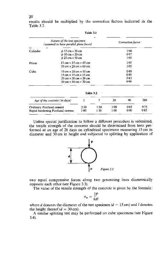
Unless special justification to follow a different procedure is submitted, the tensile strength of the concrete should be determined from tests per- formed at an age of 28 days on cylindrical specimens measuring 15 cm in diameter and 30cm in height and subjected to splitting by application of
IP
I P Figure 3.3
two equal compressive forces along two generating lines diametrically opposite each other (see Figure 3.3). The value of the tensile strength of the concrete is given by the formula:
2P 00 =-
ndl where d denotes the diameter of the test specimen (d = 15 cm) and 1 denotes the height thereof (d = 30 cm). A similar splitting test may be performed on cube specimens (see Figure
3.4).
21 In that case the value of the tensile strength of the concrete is given by the
formula : 2P
(To = ~
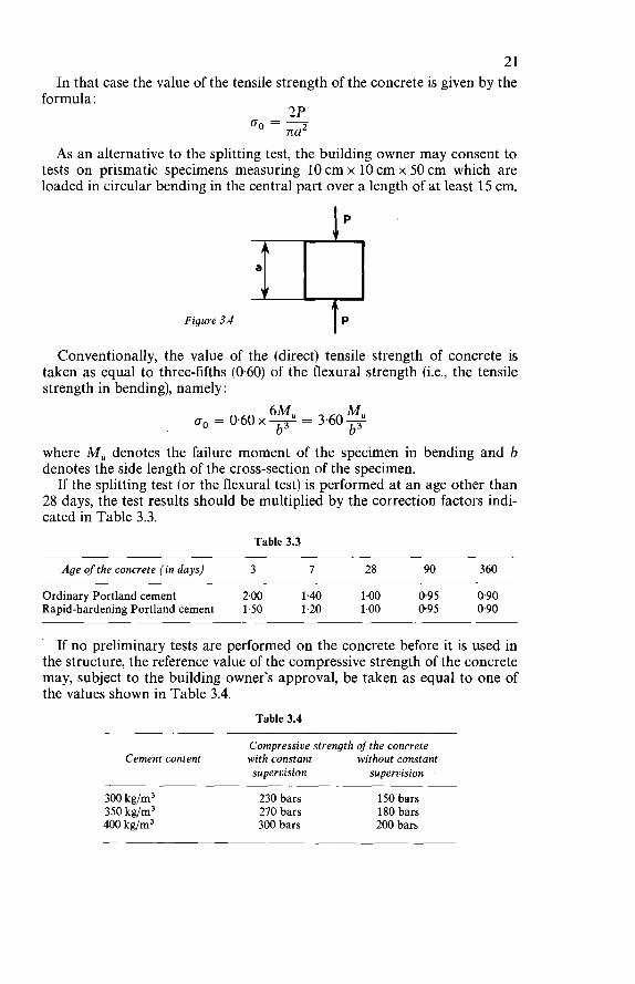
na2 As an alternative to the splitting test, the building owner may consent to
tests on prismatic specimens measuring 10 cm x 10 cm x 50 cm which are loaded in circular bending in the central part over a length of at least 15 cm.
Figure 3.4
Conventionally, the value ol the (direct) tensile strength of concrete is taken as equal to three-fifths (0.60) of the flexural strength (i.e., the tensile strength in bending), namely :
where Mu denotes the failure moment of the specimen in bending and b denotes the side length of the cross-section of the specimen.
If the splitting test (or the flexural test) is performed at an age other than 28 days, the test results should be multiplied by the correction factors indi- cated in Table 3.3.
Table 3.3
Age of the concrete (in days) 3 7 28 90 360
Ordinary Portland cement 2.00 1.40 1.00 0.95 0.90 Rapid-hardening Portland cement 1.50 1.20 1.00 0.95 0.90
If no preliminary tests are performed on the concrete before it is used in the structure, the reference value of the compressive strength of the concrete may, subject to the building owner's approval, be taken as equal to one of the values shown in Table 3.4.
Table 3.4
Compressive strength of the concrete
supervision supervision Cement content with constant without constant
300 kg/m3 350 kg/m3 400 kg/m3
230 bars 150 bars 270 bars 180 bars 300 bars 200 bars
22 These values, which have been derived from statistics of test results and are
on the safe side, do presuppose, however, that the quantity of water used for making the concrete is the least that is compatible with the conditions of placing the concrete and, furthermore, that the percentage of sand is between 30% and 50% of the total weight of the inert materials. If no preliminary tests are performed on the concrete before it is used in
the structure, the reference value of the tensile strength of the concrete may, subject to the building owner’s approvai, be derived from the corresponding compressive strength by applying the following empirical formula :
O,, = Job where o. denotes the tensile strength and ob the compressive strength of the concrete determined on cylindrical specimens, referred to an age of 28 days and expressed in bars. This empirical formula is valid for compressive strengths in the range
between 150 and 400 bars. If this formula is applied in a case where no preliminary tests are per-
formed on the concrete before it is used in the structure, the values to be adopted for the tensile strength are as follows:
for a cement content of 300 kg/m3 : for a cement content of 350 kg/m3 : for a cement content of 400 kg/m3 :
for a cement content of 300 kg/m3 : for a cement content of 350 kg/m3: for a cement content of 400 kg/m3 :
(a) with constant supervision: 15.2 bars 16.4 bars 17.3 bars
12.3 bars 13.4 bars 14.1 bars
íb) without constant supervision:
In comparison with the statistics of test results, these values are on the safe side.
3.2.2 MODULUS OF ELASTICITY OF CONCRETE
For Instantaneous Loads (Instantaneous Modulus)
For instantaneous (or rapidly changing) loads the modulus of elasticity of the concrete at an age of j days can be calculated (in bars) from the follow- ing empirical formula:
Ebo = 21 000 JoS (bars) where o; denotes the average compressive strength (in bars) of the concrete at j days. This formula can be considered valid so long as the compressive stress
in the concrete in the state under consideration does not exceed one-third of the corresponding compressive strength. Otherwise the designer should refer to the compressive stress-strain diagram for the concrete and take account of the effects of plastic behaviour and, possibly, hysteresis.
23 For Sustained Loads (Long-Term Modulus)
For loads of long duration (more than 24 hr) the modulus of elasticity of the concrete can be derived from the instantaneous modulus by taking account of long-term deformations due to the combined effect of shrinkage and creep. The basic data for this calculation,are indicated in Chapter 7, Part 2 of
this Manual. In normal cases, however, the designer may use the following approximate
formula, which is valid if the stresses are not constant: Eb, = 7000JoJ(bars)
where o; denotes the average compressive strength (in bars) of the concrete at j days.
3.2.3 POISSON’S RATIO FOR CONCRETE
Poisson’s ratio for elastic strains may be taken as 0.15.
3.2.4 COEFFICIENT OF THERMAL EXPANSION OF CONCRETE
The coefficient of thermal expansion of concrete may, on average, be taken as This is merely an average value; tests show that the coefficient of thermal
expansion may vary within a wide range (of the order of I30 %), depending on the nature of the cement and of the aggregates, the cement content, the humidity, and the dimensions of the sections. In cases where the influence of temperature variations is of particular importance the .coefficient of thermal expansion should therefore be determined experimentally from measurements on members having the same dimensions and consisting of exactly the same concrete as the actual members.
3.2.5 LONG-TERM LINEAR DEFORMATIONS OF THE CONCRETE
The values of the long-term linear deformations of concrete (shrinkage and creep) depend on a large number of parameters: dimensions of the member, water/cement ratio of the concrete, relative humidity, etc. The effect of these parameters may vary significantly from one region to another and from one country to another. These values should therefore in each case be determined experimentally from appropriate measurements on members having the same dimensions and consisting of exactly the same concrete as the actual members. Such measurements should be carried out under conditions of temperature and humidity comparable to those on the site. A set of experimental data which can provide a basis for design calculations
is given for guidance in Chapter 7, Part 2 of this Manual.
4
DETERMINATION OF SAFETY
4.1 PRINCIPLE OF CHECKING THE SAFETY
Checking the safety of a structure should, in accordance with the results of the probability theories and with the available statistical information, take account of the scatter in the various kinds of loading and in the strengths of the various constituent materials. This check should be carried out for the various limit states corresponding to the respective conditions in which the structure becomes unfit for service, including more particularly : the ultimate limit state, the limit state of instability, and the limit state of deformation, etc. Checking the safety consists in verifying that for each limit state the effects
of the ‘characteristic loadings’ (defined in Section 4.2) do not exceed the load capacity deduced from the ‘basic strengths’ (defined in Section 4.3) of the steel and concrete. This practical method of analysis is a simplification of the semi-probability
method adopted by the Conseil International du Bâtiment (C.I.B.) and the Comité Européen du Béton (C.E.B.). This simplified method is to be regarded as sufficient for all ordinary structures not exceptional in character. However, should it occur that the designer wishes to have more precise
information on the safety of the structure, and if he has at his disposal sufficient statistical data concerning the values of the loadings and strengths, he may apply, systematically and in full, the semi-probability method of the C.I.B. and C.E.B. which is explained in Chapter 2, Part 2 of this Manual.
4.2 DETERMINATION OF THE CHARACTERISTIC LOADINGS
The ‘characteristic loadings’ to be introduced into the analysis for each limit state comprise:
24
25 4.2.1 PERMANENT LOADS A N D FIXED SUPERIMPOSED
W O R K I N G LOADS, s,. The permanent loads are estimated from the volume of the materials and their density under the conditions of use. The fixed superimposed working loads should be taken as equal to the
corresponding ‘nominal superimposed loads’ specified by the building owner. If no such loads are specified, the designer may use the values given for guidance in Chapter 1, Part 2 of this Manual.
4.2.2 VARIABLE SUPERIMPOSED W O R K I N G LOADS, SPI, MULTIPLIED BY AN AMPLIFICATION COEFFICIENT EQUAL TO 1.20 FOR RESIDENTIAL BUILDINGS A N D TO 1.30 FOR OTHER STRUCTURES
The variable superimposed working loads should be taken as equal to the corresponding ‘nominal superimposed loads’ specified by the building owner. If no such loads are specified, the designer may use the values given for guidance in Chapter 1, Part 2 of this Manual. The increases of 20% or 30% applied to these nominal superimposed
loads take account of the scatter and furthermore allow for the unfavourable effect of the variation in direction and magnitude of the stresses, which is due to the variability of the superimposed loads, irrespective of any dynamic effect.
4.2.3 DYNAMIC SUPERIMPOSED WORKING LOADS, S,, , MULTIPLIED BY A ‘DYNAMIC COEFFICIENT’ SPECIFIED BY THE BUILDING O W N E R
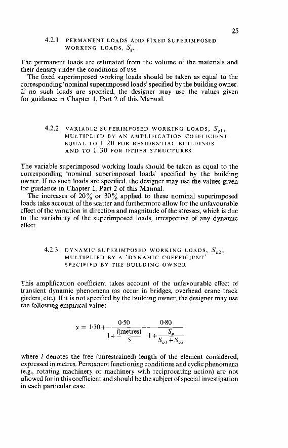
This amplification coefficient takes account of the unfavourable effect of transient dynamic phenomena (as occur in bridges, overhead crane track girders, etc.). If it is not specified by the building owner, the designer may use the following empirical value:
0.50 + 0.80 a = 1.30+ l(metres) 1 + s,
l + 5 SPI + s,, where 2 denotes the free (unrestrained) length of the element considered, expressed in metres. Permanent functioning conditions and cyclic phenomena (e.g., rotating machinery or machinery with reciprocating action) are not allowed for in this coefficient and should be the subject of special investigation in each particular case.
26 4.2.4 CLIMATIC SUPERIMPOSED LOADS S,. DUE MORE
PARTICULARLY TO W I N D A N D S N O W , A N D EARTHQUAKE ACTIONS
In the absence of special regulations concerning climatic superimposed loads the designer may use the values given for guidance in Chapter 1, Part 2 of this Manual. These values, which implicitly take the scatter into account, should be used without any increase of magnitude.
4.2.5 ACTIONS DUE TO SHRINKAGE, CREEP A N D TEMP ERA TU RE VARI AT I O N S s,
In the absence of accurate experimental data for estimating the shrinkage and creep, the designer may use the values given for guidance in Chapter 7, Part 2 of this Manual. These values should be used without any increase of magnitude.
4.2.6 THE EFFECT OF THE CONSTRUCTION PROCEDURE, W H E R E RELEVANT
The designer should examine whether, in the intermediate stages of con- struction and erection of the structure, particular loadings or particular combinations of loadings are liable to have an adverse effect on the safety of the structure and therefore call for an additional check. To sum up, the procedure for determining the ‘characteristic loadings’
to be introduced into the safety analysis for each limit state can be schemati- cally represented by the following two symbolic expressions : (a) for residential buildings :
S, + 1.20 s,, + S” + s, + . . . (b) for other structures:
S,+ 1.30 SPI +U S,, + SV+&+. . .
4.3 DETERMINATION OF THE BASIC STRENGTHS
4.3.1 DEFINITION OF BASIC STRENGTHS
The basic strength of the steel or the concrete, to be introduced into the analysis for each limit state, is taken as equal to the guaranteed minimum strength (reference strength) divided by an appropriate reduction coefficient. If the designer has at his disposal at least 20 results of preliminary tests
on the steel or the concrete to be used on the site, he may adopt instead of the guaranteed minimum strength a ‘characteristic strength’, which is taken
27 as being equal to twice the mean value of half the results that fall short of the median, minus the mean value of all the results.
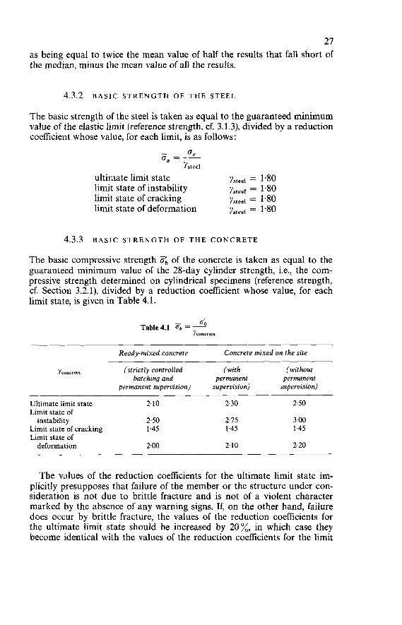
4.3.2 BASIC STRENGTH OF THE STEEL
The basic strength of the steel is taken as equal to the guaranteed minimum value of the elastic limit (reference strength, cf. 3.1.3), divided by a reduction coefficient whose value, for each limit, is as follows:
- 6, o, = __ Ysteei
ultimate limit state limit state of instability limit state of cracking limit state of deformation
Ysteei = 1.80 Ysteei = 1.80 Ysteei = 1.80 Ysteei = 1.80
4.3.3 BASIC STRENGTH OF THE CONCRETE
The basic compressive strength Ob of the concrete is taken as equal to the guaranteed minimum value of the 28-day cylinder strength, i.e., the com- pressive strength determined on cylindrical specimens (reference strength, cf. Section 3.2.1), divided by a reduction coefficient whose value, for each limit state, is given in Table 4.1.
0'0 Table4.1 ob = - Yconcrete
Ready-mixed concrete Concrete mixed on the site
Yconsreie (strictly controlled (with (without batching and permanent permanent
permanent supervision) supervision) supervision)
Ultimate limit state 2.10 Limit state of instability 2.50
Limit state of cracking 1.45 Limit state of deformation 2.00
2.30 2.50
2.75 300 1.45 1.45
210 2.20
The values of the reduction coefficients for the ultimate limit state im- plicitly presupposes that failure of the member or the structure under con- sideration is not due to brittle fracture and is not of a violent character marked by the absence of any warning signs. If, on the other hand, failure does occur by brittle fracture, the values of the reduction coeficients for the ultimate limit state should be increased by 20%, in which case they become identical with the values of the reduction coefficients for the limit
28 state of instability; this is more particularly the case with load-bearing walls and panels. Similarly, the basic tensile strength Ob of the concrete, in all cases where
this strength has to be introduced into the structural calculation, is taken as equal to the guaranteed minimum value of the 28-day tensile splitting strength, i.e., the tensile strength determined in the splitting test on cylin- drical specimens (reference strength, cf. Section 3.2.1), divided by the same reduction coefficient as for the basic compressive strength (cf. Table 4.1):
- 00 fJb = ~
Yconcreie
Furthermore, in the case of a multiple state of stress characterised by the extreme stresses o1 and o; (tensile and compressive stress respectively), the designer should also check the following condition, under the effect of the characteristic loadings :
fJ <2--- 0 0 IfJi1 1 1
Yconcreie 5 This condition is obtained by considering the corresponding limit state,
for which : - 0 1 14 I Ob = -+- 2 lo
It is equivalent to specifying that, in the case of a multiple state of stress, the designer must adopt as the basic tensile strength of the concrete the smaller of the two values:
and 2--- 0 0 132 I Yconcrete Yconcrete 5
5
DETERMINATION OF THE EFFECTS OF THE PERMANENT LOADS, SUPERIMPOSED LOADS AND OTHER ACTIONS
5.1 STRUCTURES COMPOSED OF LINEAR MEMBERS
In structures composed of linear members the effects of the loads and other actions in the various sections may be calculated by applying the elastic theory, in exact or approximate form. A redistribution of bending moments may be taken into account without
necessitating a check for compatibility in the ultimate limit state. However, to take account of such redistribution, it must be ensured that all the follow- ing conditions are satisfied :
5.1.1 IN THE ESTIMATION OF THE LOCAL STRENGTH OF SECTIONS THE STEEL STRESS TO BE TAKEN INTO ACCOUNT MUST NOT EXCEED THE BASIC STRENGTH
This condition arises more particularly in the design of the section with regard to the ultimate limit state. It means that the use of the basic diagram for the tensile reinforcing steel (Section 6.1) must be limited to the values cra d O, in all cases where redistribution of the bending moments in relation to their elastic distribution is taken into account in the calculation for a statically indeterminate structure. For practical purposes this condition applies only to cold-worked steels whose stress-strain diagram has no definite yield point.
29
30 5.1.2 NO REDISTRIBUTION MUST BE ASSUMED TO OCCUR
IN STRUCTURES IN W H I C H CRACKING IS LIABLE TO HAVE HARMFUL CONSEQUENCES
This condition is applicable more particularly to structures which have to be watertight or which are exposed to a humid or corrosive atmosphere. This condition must also be satisfied in the design calculations for statically indeterminate structures which have to support brittle facings or claddings for which excessive cracking and deformation may have harmful con- sequences.
5.1.3 THE MECHANICAL PERCENTAGE OF REINFORCEMENT IN THE LINEAR MEMBERS FORMING THE STRUCTURE MUST NOT EXCEED 0.20
The conditions of Sections 5.1.1 and 5.1.3 derive from theoretical and experi- mental considerations associated with the investigation of the equilibrium of statically indeterminate structures beyond the elastic range. In general, the first plastic deformations in the concrete appear only in
some of the critical sections. This results in a redistribution of the moments which relieves precisely those regions which are most severely stressed and delays the cracking thereof. If the loads are further increased up to failure, fresh regions subjected to
positive or negative bending moments enter the elasto-plastic range. The distribution of the moments is then much more difficult to predict, since it results from the algebraic sum of contrary effects. The danger will be greater if the redistributions produced by the inelastic deformations of opposite signs do not compensate one another, for failure is liable to occur in regions having less capacity for adaptation, whereby the safety margin for the structure as a whole could be significantly reduced. This danger exists more particularly: (a) If it is attempted to utilise to the full the strength capacity of certain
sections beyond the point corresponding to the start of large deforma- tions (i.e., beyond the basic strength of the steel i?,,), for it is not certain that the other regions can continue to adapt themselves sufficiently. This danger justifies the condition of Section 5.1.1.
(b) If certain regions of the structure have a limited capacity for adaptation, which is the case with heavily reinforced sections. This danger justifies the condition of Section 5.1.3.
5.1.4 THE EXTENT OF THE REDISTRIBUTION OF THE MOMENTS IN RELATION TO THEIR ‘ELASTIC’ VALUES MUST NOT EXCEED 15%
Any value in excess of this should be justified by means of a complete analysis of the behaviour of the statically indeterminate structure in the elasto-plastic
31 range up to failure. For that analysis it is, in particular, necessary to know the actual moment-curvature diagrams applicable to each section.
5.1.5 THE BENDING MOMENT DIAGRA‘M TAKEN INTO ACCOUNT MUST SATISFY THE EQUILIBRIUM CONDITIONS
In addition, it must in all cases be checked that the columns are able to resist the flexural loads applied to them, both on the assumption of elastic distribution of the moments and on that of moment redistribution. There are at present various methods of analysis available whereby the
inelastic behaviour and the adaptation capacity of structures consisting of linear members can be taken into account. However, the application of these methods often calls for considerable computational effort; besides, their development is not yet far enough advanced to enable them, except in special cases, to be replaced by simple approximate rules. Apart from design based on the elastic theory with a linear relation between
stress and strain, the following methods may be adopted.
Plastic Design
This is based on the hypothesis of the complete plastification of certain sections of the linear members which together form the structure and of the formation of ‘plastic hinges’ at those sections. These plastic hinges must be sufficiently numerous and be so located that the structure is transformed into a ‘mechanism’, i.e., an articulated system with at least one degree of freedom. The ‘mechanism’ and the corresponding failure load can be deduced from
the values of the plastification moments of the sections by the application of ‘static compatibility’ conditions, which yield an upper limit for the failure load, or ‘kinematic compatibility’ conditions, which yield a lower limit. The actual failure configuration and failure load are those which simultaneously satisfy the conditions of static compatibility and those of kinematic com- patibility. Generally speaking, however, reinforced concrete structures do not possess
sufficient deformation capacity to fulfil the hypotheses of plastic design. Hence this design method can be applied only within a very limited range; in particular, it must not be used if considerable redistributions of moments and forces in rrlation to the elastic distribution are necessary for attaining the failure configuration assumed in the design calculation.
Elasto-Plastic Design With Limited Rotations
This is based on the consideration of complete plastification of certain sections (‘plastic hinges’) which are so located and in such number that the structure is transformed into a statically determinate system.
32 It is assumed that the portions of members situated between the plastic
hinges retain their elastic behaviour, and a check is made to ascertain that the values of the plastic hinge rotations which are necessary for actually achieving the assumed configuration do not exceed the limiting values that these rotations can attain. The limiting values of the rotations in the plastic hinges are a function of the
section properties (geometrical shape, type and percentage of reinforcement, etc.) and of the kind of stress conditions to which those sections are sub- jected. Experimental research with a view to determining these limiting values is in progress.
Non-Linear Design
This is based on the adoption of non-linear relations between the stresses and strains in the sections of reinforced concrete structural members, for which purpose the corresponding moment-curvature diagrams are intro- duced into the calculation. In actual practice the overall results of this non-linear calculation proce-
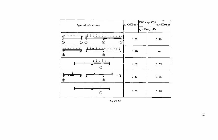
dure can be embodied in ‘redistribution coefficients’. These coefficients give the maximum alterations that can be introduced into the distribution of the resistance moments of the sections, in relation to the elastic distribution, without entailing any significant reduction in the load capacity of the struc- ture and in the corresponding margin of safety. In the present state of research, however, this analysis has as yet been
carried out only for a small number of structures and load arrangements. Figure 5.1 gives some limiting values of the ‘redistribution coefficients’,
these being applicable to normal cases, subject to an additional check of the conditions of static equilibrium. The following notation is used in the table:
p redistribution coefficient applicable to the elastic moment at the - section (ïj wo geometrical percentage of main tensile reinforcement in the section @ ce reference value of the elastic limit of the steel
5.2 PLANE STRUCTURES
5.2.1 P L A N E STRUCTURES LOADED PERPENDICULARLY TO THEIR MIDDLE PLANE
These rules relate more particularly to the analysis of the strength of slabs and flat-slab floors under flexural loading which is assumed to consist, in the main, of forces acting perpendicularly to the middle plane thereof. They do not comprise the analysis of slabs and flat-slab floors with regard to
33
2 A
O
ol -
0
d
I O
m O
al
3
u 3 L
m O
al x
L
Y
44
L
a
c
m al O
O
W O
‘O
1. c o
3 O
\ I,
O
O
m
m
W O
34 punching shear due to concentrated forces; that analysis is envisaged in Section 6.2.5. In plane structures (plates, slabs and flat-slab floors) loaded perpendicu-
larly to the middle plane the effects of the loads and other actions can be calculated by means of the exact or approximate elastic theory, provided that the actual support conditions and conditions of functioning of such structures (more particularly, the stiffness of the supports, the effect of edge beams, if any), as well as their more or less complex geometrical shapes, the actual loading conditions and any loadings of an exceptional character are taken into account. By extending the elastic theory beyond its basic assumptions it is possible
in some cases to take account of the cracking and plastification of the con- crete, particularly for the analysis of the limit state of cracking and the limit state of deformation. Research is now in progress with a view to establishing appropriate practical design methods. For checking the ultimate limit state, methods which take account of the
statically indeterminate effect of plasticity, more particularly the so-called yield-line theory, can permissibly be employed, on condition that : (a) the yield pattern of the structure under consideration is justified with
(b) the basic assumptions of these methods are really fulfilled; (c) the set of loads under consideration corresponds to the most un-
For practical application of the plastic theories it may be assumed that all the loads undergo a proportional increase in magnitude (once their most unfavourable arrangement has been determined) and that the steel and con- crete strengths are proportionally reduced. A precise analysis of the conditions of practical application of the plastic
theories, more particularly the yield-line theory, has so far been carried out only for a limited number of plane structures and methods of loading. The corresponding recommendations, together with the examples known at present, are given, as an appendix, in Chapter 8, Part 2 of this Manual.
certainty or is determined by means of appropriate tests;
favourable arrangement of these loads.
5.2.2 PLANE STRUCTURES LOADED P A R A L L E L TO THEIR MIDDLE PLANE
The structures under consideration are assumed to be loaded, in the main, by forces acting parallel to the middle plane thereof. These are structures with two dimensions large in comparison with the third and with a plane middle surface. They include more particularly: load-bearing walls and panels and deep beams (girder walls). As a secondary feature these structures may be loaded perpendicularly to the middle plane. For the purpose of the present rules the structures under consideration
are assumed to be cast in situ. Prefabricated structures, more particularly those constructed by assembling large precast panels, form the subject of a chapter of this Manual.
35 Load-bearing Partitions And Walls
Estimation Of The Effects Of The Vertical Loads
Estimating the strength of a load-bearing partition or wall involves the calculation of the magnitude and position of the resultant of the vertical components of the forces acting upon the structure. By ‘load-bearing partitions or walls’ are understood piane structures
which are used in the vertical position and have continuous support along the bottom edge. Apart from exceptional cases, in withstanding the vertical forces acting on them these structures are not subjected to bending per- pendicularly to the middle plane. Load-bearing partitions and walls generally perform either or both of
the following functions: (a) load-bearing function with regard to the vertical loads and superim-
posed loads and with regard to the vertical components of the forces due to other loadings;
(b) wind-bracing function with regard to lateral loadings acting parallel to the plane of the wall or partition.
The partitions and walls may be free along their vertical edges or be secured by stiffeners along those edges. However, in order to be considered structurally effective, the stiffener should have a width equal to a quarter of the free (unrestrained) height of the panel considered. The design should be done by the usual methods, derived from the elastic
theory of structures and, in particular, taking account of the actually existing connections between the panel under consideration and the other compo- nents of the structure. The risk of buckling should be taken into account by introducing a complementary eccentricity. Load-bearing partitions and walls have not yet been exhaustively studied
on the basis of the fundamental concept of the limit states. Hence, in the present state of knowledge, the design methods should be based on the elastic theory, in accordance with the indications given in this Manual. A concentrated load (or a load applied to an area of limited size) should
be assumed to be uniformly distributed within a zone defined by two straight lines inclined in relation to the vertical at a slope of 1 in 3 in the case of an unreinforced wall or panel, and 2 in 3 in the case of a reinforced wall or panel and starting from the point of application of the concentrated load (or from the ends of the area of application of the load). The same rule should be applied for calculating the disturbances that the
presence of openings (if any) causes in the distribution of the forces. The initial eccentricity is the resultant of (a) structural eccentricities; (b) accidental eccentricities; (c) additional eccentricities. Structural eccentricities are eccentricities arising, on the one hand, from
the eccentric positions of certain loads or superimposed loads (e.g., eccen- tricity due to changes in the thickness of a gable wall) and, on the other hand,
36 from bending moments produced by other elements of the structure (e.g., transmission of bending moments from floors to walls). These structural eccentricities should be taken into account with their appropriate algebraic signs. Accidental eccentricities are eccentricities due to faults of execution (devia-
tions from true flatness, positional errors, etc.). For want of a more accurate analysis, an overall accidental eccentricity, conventionally taken as 2 cm, should be taken into account; this eccentricity may be reduced to 1.5 cm in the case of particularly accurate and careful workmanship, but it must be increased to 2.5 cm if the formwork is of poor workmanship, liable to deform, or difficult to adjust. The overall accidental eccentricity should be taken into account with its most unfavourable algebraic sign. The designer should also take account of additional eccentricities due to
certain kinds of superimposed loads associated more particularly with the transverse bending moment produced by wind forces (pressure or suction) or with the transverse bending moment produced by the thermal gradient that may exist between the two faces of the partition or wall considered. These eccentricities should be taken into account with their appropriate algebraic signs, but in such a manner as to obtain the most unfavourable combination for the initial eccentricity. The buckling risk of a load-bearing partition or wall should be taken into
account by introducing a complementary eccentricity, e,, (or a comple- mentary bending moment). The determination of this complementary eccentricity will depend on the restraints existing along the edges of the panel considered and also on the behaviour of the type of partition or wall envisaged in the structure. In the absence of accurate experimental in- formation as to this behaviour, the following hypotheses should be adopted : (a) the Euler critical stress to be introduced into the expression for the
complementary eccentricity should be calculated on the assumption of elastic behaviour, according to the methods of the theory of elastic stability;
(b) floors should be conceived as free to move in relation to one another in the case of one-way structures, and as fixed in relation to one another in the case of two-way or multi-way structures;
(c) load-bearing panels should be conceived as hinged at the top and bottom edge; they may be regarded as rigidly restrained (built in) only if such restraint is physically assured.
The overall eccentricity to be introduced into the calculation is taken as equal to the resultant of the initial eccentricity and the complementary eccentricity:
e = e,fe,
Estimation Of The Effects Of The Horizontal Loads
The forces corresponding to the wind-bracing function of the partitions and walls should be calculated on the assumption of elastic behaviour, according to methods derived from the theory of elasticity.
37 The designer may, subject to justification, structurally interconnect a
number of panels situated in different planes but having common edges, with a view to forming wind-bracing elements with a larger moment of inertia. Such composite vertical ‘cantilevers’ should be considered as ‘thin-walled beams’. These ‘cantilevers’ may be subject to considerable torsional loads when
they undergo the effect of forces which do not pass through the centre of torsion of the corresponding section. In certain cases, also, the ‘thin-walled beams’ formed by such cantilevers may be subject to warping restraint exercised by diaphragms (floors, in particular). Chapter 8, Part 1 of this Manual indicates practical methods that may be employed for this analysis. Finally, it is necessary to bestow particular attention on the manner in which the actions tangential to the junction of two panels is equilibrated. Simplifying assumptions may be applied to the analysis of panels provided with openings: (a) If the openings are of small size, separated by lintels of sufficient
stiffness, the panels may be analysed as flat panels. The tangential actions that would occur in the panels if they were solid instead of pierced are assumed to be transmitted to the lintels.
(b) If the openings are of large size, separated merely by lintels of low stiffness, the parts of the panels separated by these openings should be conceived as structurally inter-connected so that they are compelled to undergo the same horizontal deformations. Besides, the lintels should be able to withstand the stresses due to the deformations that they are made to undergo.
(c) If the openings are of medium size, separated by lintels of medium stiffness, the panels should be analysed by an appropriate method, e.g., the method proposed in Chapter 8, Part 1 of this Manual for estimating the distribution of the forces in a pierced panel.
Chapter 8, Part 1 of this Manual also specifies the limits of the range of validity of the foregoing simplifying assumptions.
Deep Beams
Estimating the strength of a deep beam (or ‘girder wall’) involves the calcula- tion of the magnitude and position of the forces acting upon the structure. By ‘deep beams’ are here understood plane structures which are used in
any position in order to balance the forces parallel to the middle plane thereof and have discontinuous support along the edge opposite the forces. Their structural behaviour involves bending about an axis perpendicular to the middle plane. Such members may sometimes also be loaded per- pendicularly to their plane. The design should be done by the usual methods, derived from the elastic
theory of structures and from the theory relating to systems in which the deformation due to shear force is not negligible. The designer should take
38 account of the risk of buckling by transverse deflection (twist-bend instability) by applying the usual methods derived from the theory of elastic stability, taking account of such eccentricities as may be introduced by the lateral loads. A deep beam should be provided with a system of main reinforcing
bars and a system of distributed transverse bars in the form of vertical binders; there should also be horizontal reinforcement distributed over both faces of the beam. If the loads or superimposed loads are applied to the bottom part of the
beam, the vertical reinforcement of the network of distributed bars should be increased so that the additional steel cross-sectional area thus provided corresponds to the amount of load to be suspended. As regards the analysis for shear force, the shear stress to be introduced
into this analysis should be the value obtained by applying the theory of homogeneous beams and not that of reinforced concrete beams. Finally, if a deep beam is subjected not only to loads parallel to its
plane but also to flexural effects perpendicular thereto, the corresponding stresses may, as a first approximation, be estimated by adding together the stresses corresponding to each of those flexural effects considered separately. Besides, the effect of such transverse bending on the buckling conditions should be checked.
0
6
DETERMINATION OF SECTIONS
6.1 NORMAL FORCES AND STRESSES
6.1.1 ULTIMATE LIMIT STATE
Uniaxial Bending (Simple Or Composite)
Fundamental Design Assumptions
The analysis of the ultimate strength for uniaxial bending should be based on the following four fundamental assumptions:
1. The deformations (strains) of the elements of a cross-section are always proportional to the distances of these elements to the neutral axis (the ‘Navier-Bernoulli hypothesis’ which states that piane sections remain plane). This hypothesis is not strictly in agreement with reality, as experiments
show; because of (systematic or random) cracking phenomena under the usual conditions or service the longitudinal strains and stresses in reinforced concrete members do not conform to the theoretical laws of strength of materials. This is what actually occurs: (a) The longitudinal strains of the concrete and steel are not constant
along the member, even under the action of a constant bending moment. In fact, these longitudinal strains are greater at the cracks and smaller between the cracks.
(b) Progressive cracking of the tensile zone of the concrete produces, between each pair of adjacent cracks, a sliding of the reinforcement in relation to the concrete and, associated with this sliding, a local vari- ation in the bond stress and the tensile stress in the steel.
(c) In consequence, the position of the neutral axis varies all along the member.
To take all these phenomena systematically into account would too greatly complicate the designer’s task. Therefore the hypothesis that piane
39
40 sections remain plane can be regarded as a reasonable and sufficiently close approximation. 2. The compressive stress distribution in the concrete in the compressive
zone of the member is assumed to conform to a standard stress-strain diagram defined experimentally. Theoretical and experimental research has shown that the relation be-
tween the compressive stresses and the compressive strains of the concrete at a section depends not only on the quality of the concrete but also on a large number of other parameters, including: the rate and duration of application of the loads; the nature of the loadings; the position of the neutral axis in the ultimate limit state; the geometrical shape of the section; and the environment in which the member is situated. To take all these parameters systematically into account would too greatly
complicate the designer’s task. Therefore the main object of theoretical and experimental research has been to determine simplified standard diagrams which are easy to apply in the usual design calculations and which lead to results that are close to the theoretically predicted and experimentally measured values. 3. The tensile strength of the concrete is neglected. 4. The tensile (and compressive) steel stresses are deduced, on application
of the hypothesis that plane sections remain plane (see Assumption i), from conventional stress-strain diagrams based on the standard stress-strain diagrams for ordinary steels and cold-worked steels and valid up to a strain of 1%.
Taking Account Of The Concrete In Compression
The notion ‘width of the compressive zone’ has a real significance only in the case of rectangular sections or sections similar to them. In a rectangular section the width of the compressive zone obviously
corresponds to the geometrical width of the section. In the case of T-beams and ribbed floors a conventional value, the ‘effective
width of the compressive flange’, is introduced into the calculation. This effective width defines the width of the compressive zone that effectively participates in the flexural load capacity of the member. The effective width of the compressive flange of a T-section depends on a
large number of parameters, including: the support conditions of the beam considered (freely supported or continuity at the supports); the method of load application (distributed loads or locally concentrated loads); the ratio of the length of the beam (between free supports or between points of zero bending moment) to the width of the rib (or web) and to the distance between consecutive ribs; the ratio of the thickness of the flange (or slab) to the depth of the beam; and the presence (if any) of fillets or haunches at the junction of flange and rib. From an analysis of the effect of these various parameters it has been
possible to establish a practical method of determining the effective width
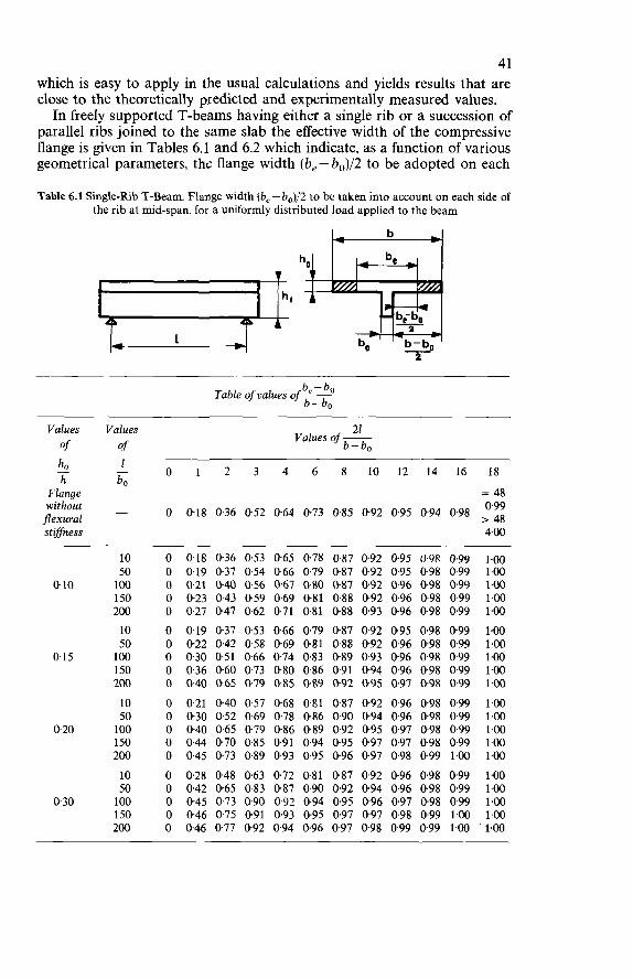
41 which is easy to apply in the usual calculations and yields results that are close to the theoretically predicted and experimentally measured values. In freely supported T-beams having either a single rib or a succession of
parallel ribs joined to the came slab the effective width of the compressive flange is given in Tables 6.1 and 6.2 which indicate, as a function of various geometrical parameters, the flange width (b, - b,)/2 to be adopted on each
Table 6.1 Single-Rib T-Beam. Flange width (be - b0)/2 to be taken into account on each side of the rib at mid-span, for a uniformly distributed load applied to the beam
b e - bo Table oJvalues of- b-bo
Values of
h Flange without flexural stgfness
- ho
Values of 1 bo -
21 b-bo
Values of ~
O 1 2 3 4 6 8 1 0 1 2 1 4 1 6 18
= 48 0.99 , 48 4.00
O 0,18 0-36 052 0.64 0.73 0.85 0.92 0.95 0.94 0.98
0.10
015
0.20
0.30
10 50 100 150 200 10 50 1 O0 150 200 10 50 100 150 200 10 50 100 150 200
O 0.18 0.36 0.53 0.65 0.78 087 0.92 0.95 0.98 0.99 1.00 O 0.19 037 0.54 0.66 0.79 0.87 092 0.95 0.98 0.99 1.00 O 0.21 0.40 0.56 0.67 0.80 0.87 0.92 0.96 098 0.99 1.00 O 0.23 043 0.59 0.69 0.81 0.88 0.92 0.96 0.98 0.99 1.00 O 0.27 0.47 0.62 0.71 0.81 0.88 0.93 0.96 0.98 0.99 1.00 O 0.19 037 0.53 0.66 0.79 0.87 0.92 0.95 0.98 0.99 1.00 O 0.22 0.42 0.58 0.69 0.81 0.88 0.92 0.96 0.98 0.99 1.00 O 0.30 0.51 0.66 0.74 0.83 0.89 0.93 096 0.98 0.99 1.00 O 036 0.60 0.73 0.80 0.86 0.91 0.94 0.96 0.98 0.99 1.00 O 0.40 0.65 0.79 0.85 0.89 0-92 0.95 0.97 0.98 0-99 1-00 O 0.21 0.40 0.57 0.68 0.81 0.87 0.92 0.96 0.98 0.99 1.00 O 0.30 0.52 0.69 0.78 0.86 0.90 0.94 096 0.98 0.99 1.00 O 0.40 0.65 0.79 0.86 0.89 092 0.95 0.97 0.98 0.99 1.00 O 0.44 0.70 0.85 0.91 0.94 0.95 0.97 0.97 0.98 0.99 1.00 O 0.45 0.73 0.89 0.93 0.95 0.96 0.97 0.98 0.99 1.00 1.00 O 0.28 0.48 0.63 0.72 0.81 0.87 092 0.96 0.98 099 1.00 O 0.42 0.65 0.83 0.87 090 0.92 0.94 0.96 0.98 0.99 1.00 O 0.45 0.73 0.90 0.92 0.94 0.95 0.96 0.97 0.98 0.99 1.00 O 0.46 0.75 0.91 0.93 0.95 0.97 0.97 0.98 0.99 1.00 1.00 O 0.46 0.77 0.92 0.94 0.96 0.97 0.98 0.99 099 14û i.00
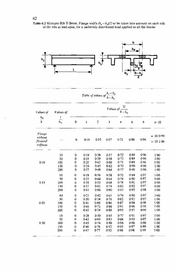
42 Table 6.2 Multiple-Rib T-Beam. Flange width (be - b0)/2 to be taken into account on each side
of the ribs at mid-span, for a uniformly distributed load applied to all the beams
be - bo Table of values of ~
b-bo
21 Values of -
Values of Values of b-bo 1 - h0
h bo o 1 2 3 4 6 8 2 10 -
Flnnye without flexural stflness
= 10 0.99 O 0.19 0.33 0.57 071 088 0.96 , l.oo
10 50
0.10 100 150 200 10 50
0,15 1 O0 150 200 LO 50
0.20 1 O0 150 200 10 50
0.30 100 150 200
O 0.19 0.38 0.57 0.72 089 O 0.19 0.39 058 0.73 0.89 O 0.21 0.42 0.60 075 0.89 O 0.24 0.45 0.62 0.75 090 O 027 0.48 0.64 0.77 090 O 0.19 0.39 0.58 0.72 0.89 O 0.23 0.44 0.64 074 0.90 O 0.31 0.53 0.68 0.78 091 O 0.37 0.61 0.74 083 092 O 0.41 0.66 080 0.87 095 O 0.21 0.42 0.61 074 090 O 030 0.54 071 082 092 O 0.41 0.66 0.80 087 094 O 0.44 0.71 0.86 091 096 O 0.45 0.74 0.89 093 097 O 0.28 0.50 0.65 077 0.91 O 0.42 0.69 083 088 093 O 0.45 0.74 0.90 094 096 O 0.46 076 092 095 097 O 0.47 0.77 092 096 098
0.96 096 096 096 096 097 0.97 097 097 098 097 097 098 0.98 099 097 0.97 098 099 0.99
1.00 1 .o0 1.00 1.00 1.00 1.00 1 .o0 1.00 1.00 1-00 1.00 1-00 1 .o0 1.00 1.00
1 .o0 1.00 1 .o0 1-00 1

43 side of the rib. These numerical tables are valid in the case of distributed loads (uniform or practically uniform, triangular, parabolic or sinusoidal distribution). In the case of a locally concentrated load aptdied to a zone of width a the
values given in Tables 6.1 and 6.2 should be multiplied by a reduction coeffi- cient as shown in Table 6.3.
Table 6.3
Reduction coefficient for 21
b-bo Values of-
__ O 10 20 be -bo b-bo
~~ ~
a s 0 0.6 0.7 0.9
O < a < li10 Loca I1 y
concentrated linear interpolation between the extreme values load above and below
a 2 1/10 1 .o 1.0 1.0
Furthermore, in the vicinity of a free support the flange width (be - b0)/2 to be taken into account on each side of the rib must not exceed the distance from the support to the section considered. For continuous T-beams and, more generally, for T-beams in which, for a
particular loading condition, changes occur in the sign of the bending moment, the method of determining the effective width of the compressive flange is the same as that for simply-supported T-beams, provided that instead of the free span length 1 the distance between the points of zero bending moment is adopted. If the rib of the T-beam considered is joined to the compressive flange by
haunches having a width b, and a depth h,, then the actual width bo of the rib should be replaced in the calculation by a fictitious width b, which should be taken as equal to:
b, = bo+2b,$b,<h, b, = bo+2h,ifb,>h,
The maximum compressive strain of the concrete in uniaxial (simple or composite)* bending is conventionally taken as equal to 0.2%. Experimental results show that the value of the maximum compressive
strain (shortening) of concrete in the ultimate limit state may vary con- siderably, depending on the rate and duration of the load application, the environment, the geometrical shape of the section, the percentage of rein- forcement, the eccentricity of the direct (or normal) force applied, and the
*‘Composite’ bending is the combination of bending moment and direct force (longitudinal force in the member); if there is no direct force acting, ‘simple’ bending occurs.
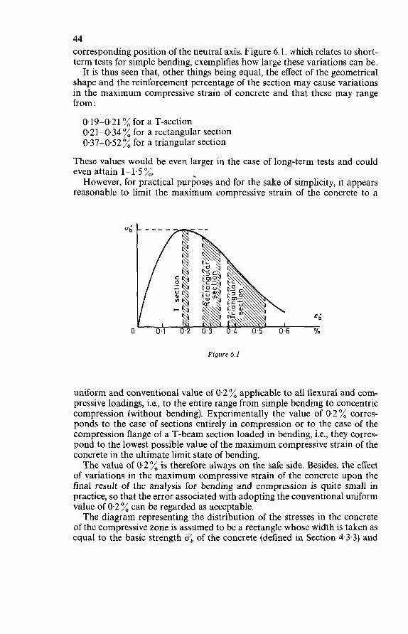
44 corresponding position of the neutral axis. Figure 6.1. which relates to short- term tests for simple bending, exemplifies how large these variations can be. It is thus seen that, other things being equal, the effect of the geometrical
shape and the reinforcement percentage of the section may cause variations in the maximum compressive strain of concrete and that these may range from:
0.19-0.21 % for a T-section 0.21-0.34 % for a rectangular section 0.37-0.52 % for a triangular section
These values would be even larger in the case of long-term tests and could even attain 1-1.5 %. However, for practical purposes and for the sake of simplicity, it appears
reasonable to limit the maximum compressive strain of the concrete to a
Figure 6.1
uniform and conventional value of 0.2 % applicable to all flexural and com- pressive loadings, i.e., to the entire range from simple bending to concentric compression (without bending). Experimentally the value of 0.2 % corres- ponds to the case of sections entirely in compression or to the case of the compression flange of a T-beam section loaded in bending, i.e., they corres- pond to the lowest possible value of the maximum compressive strain of the concrete in the ultimate limit state of bending. The value of 0.2% is therefore always on the safe side. Besides, the effect
of variations in the maximum compressive strain of the concrete upon the final result of the analysis for bending and compression is quite small in practice, so that the error associated with adopting the conventional uniform value of 0.2 % can be regarded as acceptable. The diagram representing the distribution of the stresses in the concrete
of the compressive zone is assumed to be a rectangle whose width is taken as equal to the basic strength Ob of the concrete (defined in Section 43.3) and
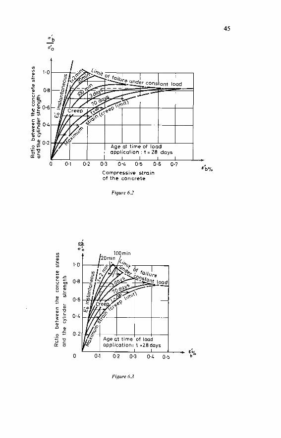
45
u) u)
2 4
Figure 6.2
0; 100min t /20rni" I,
Figure 6.3
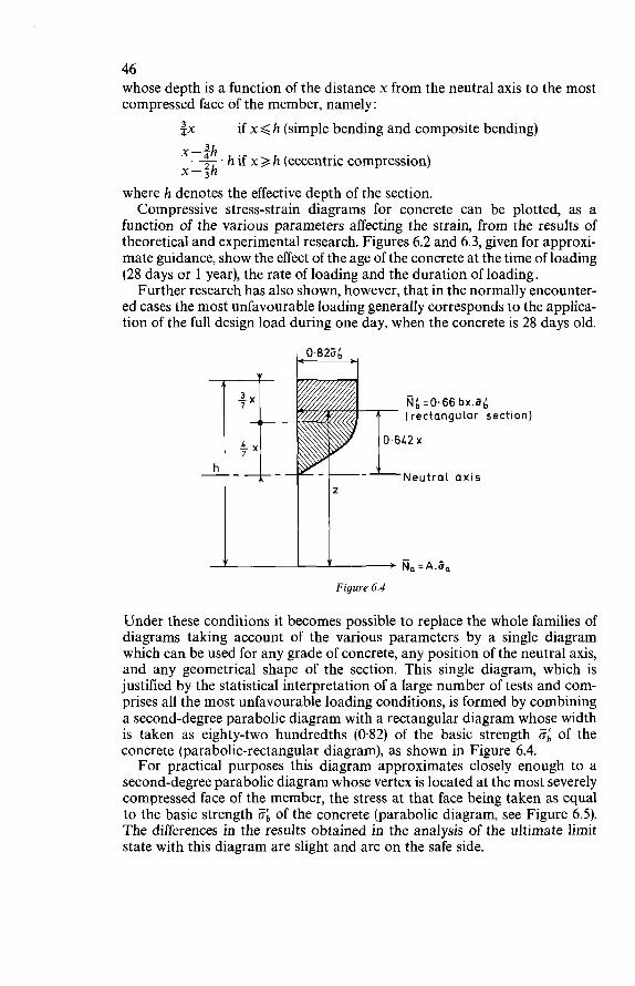
46 whose depth is a function of the distance x from the neutral axis to the most compressed face of the member, namely:
$X if x 6 h (simple bending and composite bending) x -ah -. h if x 3 h (eccentric compression) x-3h
where h denotes the effective depth of the section. Compressive stress-strain diagrams for concrete can be plotted, as a
function of the various parameters affecting the strain, from the results of theoretical and experimental research. Figures 6.2 and 6.3, given for approxi- mate guidance, show the effect of the age of the concrete at the time of loading (28 days or 1 year), the rate of loading and the duration of loading. Further research has also shown, however, that in the normally encounter-
ed cases the most unfavourable loading generally corresponds to the applica- tion of the full design load during one day, when the concrete is 28 days old.
(rectangular section)
Neutral axis
m,, :A.Ü, Figure 6.4
Under these conditions it becomes possible to replace the whole families of diagrams taking account of the various parameters by a single diagram which can be used for any grade of concrete, any position of the neutral axis, and any geometrical shape of the section. This single diagram, which is justified by the statistical interpretation of a large number of tests and com- prises all the most unfavourable loading conditions, is formed by combining a second-degree parabolic diagram with a rectangular diagram whose width is taken as eighty-two hundredths (0.82) of the basic strength 5; of the concrete (parabolic-rectangular diagram), as shown in Figure 6.4. For practical purposes this diagram approximates closely enough to a
second-degree parabolic diagram whose vertex is located at the most severely compressed face of the member, the stress at that face being taken as equal to the basic strength 6 of the concrete (parabolic diagram, see Figure 6.5). The differences in the results obtained in the analysis of the ultimate limit state with this diagram are slight and are on the safe side.
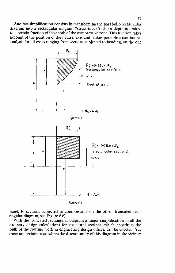
47 Another simplification consists in transforming the parabolic-rectangular
diagram into a rectangular diagram (‘stress block’) whose depth is limited to a certain fraction of the depth of the compressive zone. This fraction takes account of the position of the neutral axis and makes possible a continuous analysis for all cases ranging from sections subjected to bending, on the one
(rectangu lar sect ions)
- Neutral axis
L- Na = A.äa Figure 6.5
(re c tang u Lar sect ions)
Figure 6.6
hand, to sections subjected to compression, on the other (truncated rect- angular diagram, see Figure 6.6). With the truncated rectangular diagram a major simplification in all the
ordinary design calculations for structural sections, which constitute the bulk of the routine work in engineering design offices, can be effected. Yet there are certain cases where the discontinuity of this diagram in the vicinity
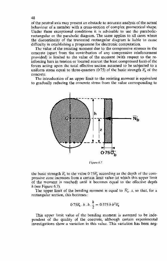
48 of the neutral axis may present an obstacle to accurate analysis of the actual behaviour of a member with a cross-section of complex geometrical shape. Under these exceptional conditions it is advisable to use the parabolic- rectangular or the parabolic diagram. The same applies to all cases where the discontinuity of the truncated rectangular diagram is liable to cause difficulty in establishing a programme for electronic computation. The value of the resisting moment due to the compressive stresses in the
concrete (apart from the contribution of any compressive reinforcement provided) is limited to the value of the moment (with respect to the re- inforcing bars in tension or located nearest the least compressed face) of the forces acting upon the total effective section assumed to be subjected to a uniform stress equal to three-quarters (0.75) of the basic strength ob of the concrete. The introduction of an upper limit to the resisting moment is equivalent
to gradually reducing the concrete stress from the value corresponding to
Figure 6.7
the basic strength ab to the value 0.75Zb according as the depth of the com- pressive zone increases from a certain limit value (at which this upper limit of the moment is reached) until it becomes equal to the effective depth h (see Figure 6.7). The upper limit of the bending moment is equal to NI,. z, so that, for a
rectangular section, this becomes :
h 2 0.7501,. b . h .- = 0.375 b h2%
This upper limit value of the bending moment is assumed to be inde- pendent of the quality of the concrete, although certain experimental investigations show a variation in this value. This variation has been neg-
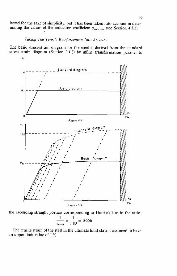
49 lected for the sake of simplicity, but it has been taken into account in deter- mining the values of the reduction coefficient yconcrete (see Section 4.3.3).
-
Taking The Tensile Reinforcement Into Account
The basic stress-strain diagram for the steel is derived from the standard stress-strain diagram (Section 3.1.3) by affine transformation parallel to
I
eo.*------- _ _ _ _ _ _ ,---- I ,I-- I ,r I 1
‘ I I I I I II
1 9 1 /I I ‘II I I I
,I 1 / I
I ,I / Basic /diagram I III I
Figure 6.8 ea I
the ascending straight portion corresponding to Hooke’s law, in the ratio :
= 0.556 1 - 1 Ysteei 1.80
The tensile strain of the steel in the ultimate limit state is assumed to have an upper limit value of 1 %.
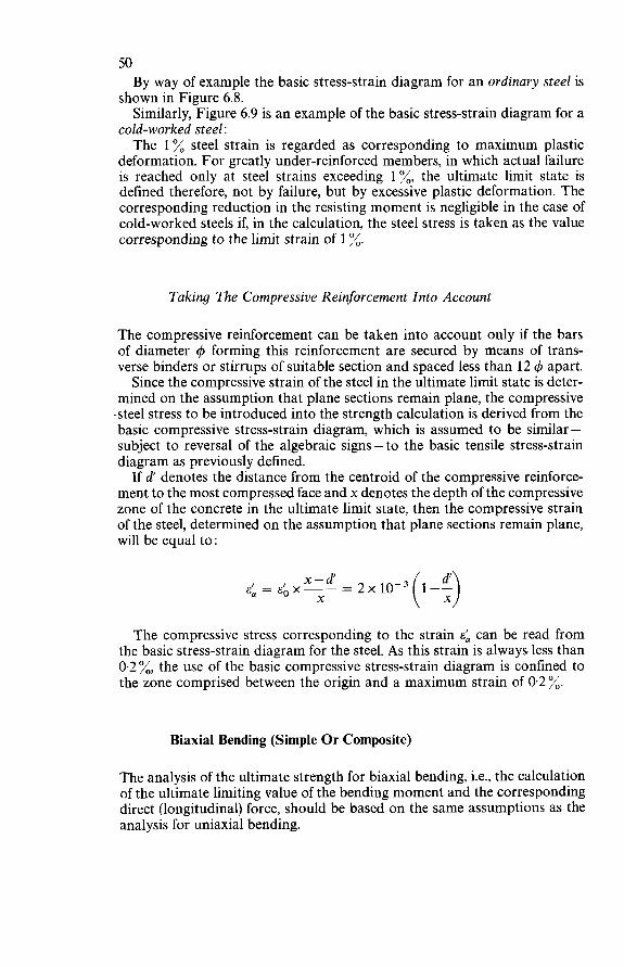
50 By way of example the basic stress-strain diagram for an ordinary steel is
shown in Figure 6.8. Similarly, Figure 6.9 is an example of the basic stress-strain diagram for a
cold-worked steel: The 1% steel strain is regarded as corresponding to maximum plastic
deformation. For greatly under-reinforced members, in which actual failure is reached only at steel strains exceeding 1 x, the ultimate limit state is defined therefore, not by failure, but by excessive plastic deformation. The corresponding reduction in the resisting moment is negligible in the case of cold-worked steels if, in the calculation, the steel stress is taken as the value corresponding to the limit strain of 1 %.
Taking The Compressive Reinforcement Into Account
The compressive reinforcement can be taken into account only if the bars of diameter 4 forming this reinforcement are secured by means of trans- verse binders or stirrups of suitable section and spaced less than 12 4 apart. Since the compressive strain of the steel in the ultimate limit state is deter-
mined on the assumption that plane sections remain plane, the compressive .steel stress to be introduced into the strength calculation is derived from the basic compressive stress-strain diagram, which is assumed to be similar - subject to reversal of the algebraic signs - to the basic tensile stress-strain diagram as previously defined. If d' denotes the distance from the centroid of the compressive reinforce-
ment to the most compressed face and x denotes the depth of the compressive zone of the concrete in the ultimate limit state, then the compressive strain of the steel, determined on the assumption that plane sections remain plane, will be equal to :
The compressive stress corresponding to the strain E; can be read from the basic stress-strain diagram for the steel. As this strain is always less than 0.2%, the use of the basic compressive stress-strain diagram is confined to the zone comprised between the origin and a maximum strain of 0.2 %.
Biaxial Bending (Simple Or Composite)
The analysis of the ultimate strength for biaxial bending, i.e., the calculation of the ultimate limiting value of the bending moment and the corresponding direct (longitudinal) force, should be based on the same assumptions as the analysis for uniaxial bending.
51 Bending is called ‘biaxial’ when the axis of the bending couple does not
coincide with one of the central axes of inertia of the section. However, the analysis for biaxial bending can generally be avoided in the
frequently encountered case of edge beams of ribbed slabs. Because of the asymmetry, these edge beams are subjected to biaxial bending, but for practi- cal purposes their sections can be designed as though for uniaxial bending, because the stiffness of the slab to which they are joined is generally sufficient to prevent any significant deviation of the neutral axis.
Concentric Compression
Members Without Binding
The analysis of the ultimate strength for concentric (or axial) compression should be based on the same fundamental assumptions as the analysis for uniaxial bending. These fundamental assumptions are valid in an entirely continuous
fashion throughout the range of simple or composite uniaxial bending, i.e., the whole range extending from simple bending to concentric com- pression. The load capacity analysis for concentric compression in the limit state is
considered to be adequate for all compression members whose Euler slender- ness ratio does not exceed 40. Otherwise this analysis should be supplemented by an analysis for the resistance capacity in the limit state of instability. The limiting value for the concrete and steel strains in the ultimate limit
state is conventionally taken as 0.2 %. This corresponds to the strain hypothesis relating to uniaxial bending. The compressive concrete stress in the ultimate limit state is taken as
seventy-five hundredths (0.75) of the basic strength O;, of the concrete (as defined in Section 4.3.3). This corresponds to the stress hypothesis relating to uniaxial bending. The compressive reinforcement can be taken into account only if the
bars of diameter q5 forming this reinforcement are secured by means of trans- verse binders or links of suitable section and spaced less than 12 4 apart. The compressive steel strain in the ultimate limit state is taken as 0.2%.
The compressive steel stress to be adopted in the strength calculation is derived from the basic compressive stress-strain diagram, which is assumed to be similar - subject to reversal of the algebraic signs - to the basic tensile stress-strain diagram as defined above. This corresponds to the hypothesis relating to uniaxial bending. O n application of this hypothesis and the preceding one, the value of the
1. a force equal to the product of the total cross-sectional area of the concrete of the member and seventy-five hundredths (0.75) of the basic strength a;, of the concrete, and
2. a force equal to the product of the total cross-sectional area of the com-
ultimate limiting value of the force is obtained as the sum of:
52 pressive reinforcement and the stress O:, corresponding to a strain of 0.2 % in the basic stress-strain diagram for the steel.
Therefore: NI = B x 0.756 + A’%’
Members Reinforced By Binding
Binding can be employed for compression members with the object of improving their strength with regard to local loads, their impact strength, and their ductility at fracture, but it should strictly be confined to special purposes. The principle of ‘binding’ is to provide lateral restraint and thus prevent
transverse expansion of the concrete loaded in compression. This restraint is obtained by means of very tightly and closely applied reinforcement, with the result that an apparent increase in the strength of the concrete is achieved. In practice, binding should be used only for local reinforcement, e.g., at
hinges and bearings having to transmit concentrated loads. O n no account is it to be treated as a mere expedient of calculation by means of which it is always possible to satisfy the requirements for checking the ultimate limit state for compression. The effect of binding can be taken into consideration in the analysis of the
ultimate limit state for concentric compression only if the following four conditions are satisfied:
1. The height of the zone provided with binding in a compression member should not exceed twice the least transverse dimension of that member. Binding is efficient only in short members. In the case of long mem-
bers provided with binding, the concrete within the core enclosed by the binding is in a state of plastification and thus creates a danger of buckling which may bring about premature destruction by bursting.
2. The least transverse dimension of the zone provided with binding should be not less than 0.25 m.
If the transverse dimensions of the member are too small, it may not be possible to construct the binding properly.
3. The binding should be formed by either of the following methods of installing transverse reinforcement, no other method being permissible. (a) Binding by helical reinforcement or hoops:
The binding of a member of circular cross-section may be in the form of a continuous circular helix or of a series of closed hoops. The pitch of the helix or the spacing of the hoops should not exceed one-fifth (0.20) of the diameter of the core enclosed by the binding.
The binding in a member of rectangular cross-section may con- sist of mats formed of bars bent hairpin-wise to and fro, these mats being placed with the bars extending alternately in mutually per- pendicular directions and suitably anchored into the concrete. The spacing of these mats should not exceed one-fifth (0.20) of the least dimension of the core provided with binding reinforcement.
(b) Binding reinforcement in mats:
53 4. The geometrical percentage of binding reinforcement, referred to the
total volume of the zone provided with binding, should be at least 0.6 %.
The calculation of the ultimate strength of a member provided with binding should be based, not on the total cross-section of the member, but only upon the cross-section of the core enclosed by the binding and bounded by the outer edge thereof. In a member provided with binding, the compressive concrete stress in the
limit state should be taken as seventy-five hundredths (0.75) of the basic strength ob of the concrete (defined in Section 4.3.3), multiplied by an amplifi - cation coefficient that takes the effect of the binding into account ('binding coefficient'). Depending on the method of transverse reinforcement (binding) applied,
the binding coefficient is taken as one of the two following values, but must never exceed the upper limit of 2.50: (a) Binding by helical reinforcement or hoops:
(b) Binding reinforcement in mats:
In these expressions Zio denotes the geometrical percentage of longitudinal compressive reinforcement and Oi denotes the geometrical percentage of transverse reinforcement employed as binding, both percentages being referred to the total volume of the zone provided with binding. In the second expression denotes the diameter (in centimetres) of the transverse rein- forcement employed as binding.
Concentric Tension
In the analysis of the ultimate strength for concentric tension only the strength of the tensile reinforcement should be taken into account, ignoring the tensile strength of the concrete. This basic assumption applies not only to the case of concentric tension,
but also to tension occurring in combination with bending, insofar as the entire section of the concrete is actually in tension. If not, the compressive zone of the concrete section may be taken into account in calculating the ultimate strength. The analysis of the ultimate strength for concentric tension should be
supplemented by a check on the limit state of cracking (Section 6.1.3), having due regard to the environmental and service conditions of the member considered.
54 It may occur, however, that no cracking whatsoever is acceptable because
of special circumstances (e.g., structures enclosing nuclear reactors). In such cases the analysis for the limit state of failure (ultimate strength analysis) should be replaced by an analysis for the limit state of concrete strain whereby it can be checked that the strains developed in the concrete remain below the strain associated with tensile failure (which may, for example, be taken as 0.01 %). In addition, it is necessary in such cases to take the unfavourable effect of shrinkage into account, while the possible favourable effect of creep should be ignored. Finally, despite these very severe conditions, the tensile strength of the concrete-even though it is assumed to be uncracked -should be neglected, just as is ordinarily done.
6.1.2 LIMIT STATE OF INSTABILITY
Fundamental Design Assumptions
The analysis of the critical strength for uniaxial bending in the limit state of instability, i.e., the calculation of the limiting value of the buckling moment and the corresponding direct (longitudinal) force, is reducible to the ultimate strength analysis (Section 6.1.1) by conventionally introducing a com- plementary eccentricity for the direct force.* This assumption, which is applicable to the analysis of buckling in the
case of uniaxial bending, may be extended to the analysis of buckling in the case of biaxial bending. It should not, however, be applied to the analysis of twist-bend buckling, i.e., checking the strength of a member with regard to lateral instability due to buckling associated with bending; in that case the designer should apply the standard theories of structural stability. For practical purposes the above assumption consists in transforming the
analysis for the limit state of instability into the usual analysis of the ultimate limit state for eccentric compression or composite bending. Consider a member subjected to that longitudinal compression. At any
particular cross-section of that member the direct force has a total eccen- tricity comprising: (a) the known or intentional eccentricity due to deliberate structural
(b) the accidental and inevitable eccentricity due to inaccuracies of
(c) the deflection due to the flexural deformations arising from the two
It thus appears that, in terms of actual structural behaviour, concentric compression is merely a hypothetical ideal condition; in reality, bending always complicates the issue. For this reason the validity of applying the standard theory of elastic buckling of reinforced concrete members may well *‘Direct îorce’ (or ‘normal force’) denotes a force acting parallel to the longitudinal axis of a member. If the line of action of this force coincides with the centroidal axis of the member, the condition is called ‘concentric’ (or ‘axial’) compression or tension, as the case may be.
arrangements ;
construction ;
foregoing eccentricity components (a) and (b).
55 be questioned. Accordingly, for checking a member with regard to the limit state of instability, it appears advisable to turn to an analogy calculation based on the knowledge of the maximum deformations of the member in the ultimate limit state and enabling the critical buckling strength to be estimated in a simple manner by applying the usual ultimate strength analysis for eccentric compression and composite bending. In short, the analysis for buckling involves adding a bending moment
(referred to as the ‘additional bending moment’) to the initial loading system on which the design of the section for the ultimate limit state is based. The analysis of the critical strength in the limit state of instability is
necessary for all compression members whose Euler slenderness ratio exceeds 40. Otherwise the ultimate strength analysis (i.e., the ordinary analysis of the strength of the member in the limit state of failure) will suffice. In accordance with Euler’s theory the slenderness ratio A of a member is
defined as the ratio of the effective length 1, to the radius of gyration i of the (net) concrete cross-section in the corresponding plane :
1, A = y
1
The effective length 1, depends upon the structural features in any particular case. If 1 denotes the geometrical length of the member under consideration, the effective length 1, is equal to:
if the member is free at one end and fixed (rigidly restrained) at the other; if the member is hinged (pin-jointed) at both ends or, alter- natively, if it can be considered fixed at both ends, but these ends can move in relation to each other in a direction per- pendicular to the longitudinal axis of the member and situated in the principal plane for which buckling is being investigated;
1, = l/ J2 if the member is hinged at one end and fixed at the other; 1, = 112 if the member can be considered fixed at both ends and those
ends cannot move. In the frequently encountered case of a multi-storey building in which
the continuity of the columns and their sections is assured, the effective length 1, may be equal to:
if the ends of the column are either rigidly fixed to a foundation block or are joined to floor beams which have at least the same moment of inertia as the column in the direction considered and which extend on both sides of it;
1, = 1/1.15 in all other cases. In practice, one of the difficulties of the analysis consists in correctly
estimating the actual degree of fixity (degree of restraint) of the connection between ‘the member under consideration and the other elements of the structure. A convenient empirical method consists in comparing, at each joint, in a given plane, the stiffness of the supporting member with the sum of the stiffnesses of the supported members:
1, = 21
1, = 1
1, = l/ J2
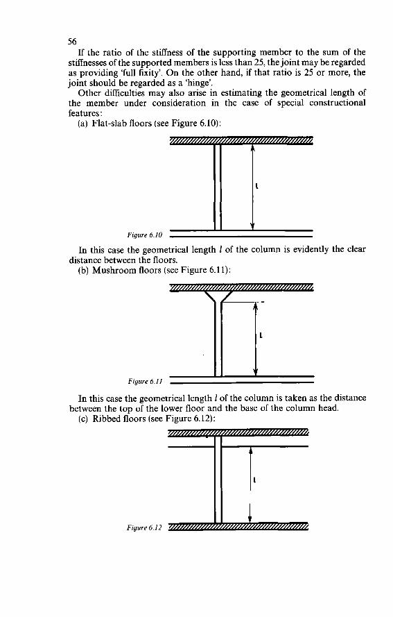
56 If the ratio of the stiffness of the supporting member to the sum of the
stiffnesses of the supported members is less than 25, the joint may be regarded as providing ‘full fixity’. O n the other hand, if that ratio is 25 or more, the joint should be regarded as a ‘hinge’.
Other difficulties may also arise in estimating the geometrical length of the member under consideration in the case of special constructional features : (a) Flat-slab floors (see Figure 6.10): -
1
Figure 6.10 1 In this case the geometrical length 1 of the column is evidently the clear
(b) Mushroom floors (see Figure 6.11): distance between the floors.
Figure 6.11 c In this case the geometrical length 1 of the column is taken as the distance
(c) Ribbed floors (see Figure 6.12): between the top of the lower floor and the base of the column head.
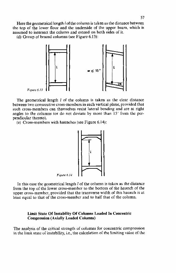
57 Here the geometrical length 1 of the column is taken as the distance between
the top of the lower floor and the underside of the upper beam, which is assumed to intersect the column and extend on both sides of it. (d) Group of braced columns (see Figure 6.13):
Figure 6.13 D The geometrical length 1 of the column is taken as the clear distance
between two consecutive cross-members in each vertical plane, provided that such cross-members can themselves resist lateral bending and are at right angles to the columns (or do not deviate by more than 15" from the per- pendicular thereto). (e) Cross-members with haunches (see Figure 6.14):
Figure 6.14
In this case the geometrical length 1 of the column is taken as the distance from the top of the lower cross-member to the bottom of the haunch of the upper cross-member, provided that the transverse width of this haunch is at least equal to that of the cross-member and to half that of the column.
Limit State Of Instability Of Columns Loaded In Concentric Compression (Axially Loaded Columns)
The analysis of the critical strength of columns for concentric compression in the limit state of instability, i.e., the calculation of the limiting value of the
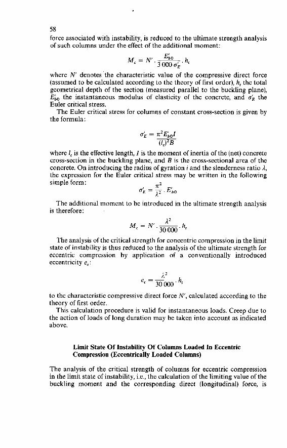
58 force associated with instability, is reduced to the ultimate strength analysis of such columns under the effect of the additional moment:
GO M, = N.- 3 O00 o; ' ht where N denotes the characteristic value of the compressive direct force (assumed to be calculated according to the theory of first order), h, the total geometrical depth of the section (measured parallel to the buckling plane),
the instantaneous modulus of elasticity of the concrete, and oE the Euler critical stress. The Euler critical stress for columns of constant cross-section is given by
the formula:
where 1, is the effective length, I is the moment of inertia of the (net) concrete cross-section in the buckling plane, and B is the cross-sectional area of the concrete. O n introducing the radius of gyration i and the slenderness ratio A, the expression for the Euler critical stress may be written in the following
n2 simple form:
E. 0; = T. E b O
The additional moment to be introduced in the ultimate strength analysis is therefore:
A2 M, = NI.- 30 O00 ' ht The analysis of the critical strength for concentric compression in the limit
state of instability is thus reduced to the analysis of the ultimate strength for eccentric compression by application of a conventionally introduced eccentricity e, :
A2 30 O00 ' e, = -
to the characteristic compressive direct force N', calculated according to the theory of first order. This calculation procedure is valid for instantaneous loads. Creep due to
the action of loads of long duration may be taken into account as indicated above.
Limit State Of Instability Of Columns Loaded In Eccentric Compression (Eccentrically Loaded Columns)
The analysis of the critical strength of columns for eccentric compression in the limit state of instability, i.e., the calculation of the limiting value of the buckling moment and the corresponding direct (longitudinal) force, is
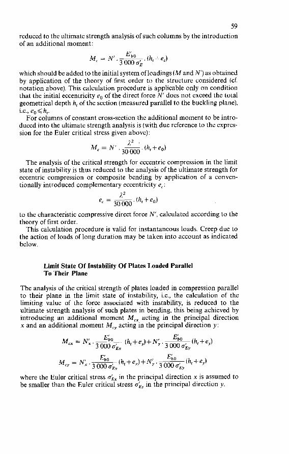
59 reduced to the ultimate strength analysis of such columns by the introduction of an additional moment:
. (h, 1- e,) Ek0 3 O00 o; M, = N.-
which should be added to the initial system of loadings (M and N') as obtained by application of the theory of first order to the structure considered (cf. notation above). This calculation procedure is applicable only on condition that the initial eccentricity eo of the direct force N' does not exceed the total geometrical depth h, of the section (measured parallel to the buckling plane), i.e., eo < h,. For columns of constant cross-section the additional moment to be intro-
duced into the ultimate strength analysis is (with due reference to the expres- sion for the Euler critical stress given above):
The analysis of the critical strength for eccentric compression in the limit state of instability is thus reduced to the analysis of the ultimate strength for eccentric compression or composite bending by application of a conven- tionally introduced complementary eccentricity e, :
/I2 e, = - 3o 000 ' (hf +eo)
to the characteristic compressive direct force N', calculated according to the theory of first order. This calculation procedure is valid for instantaneous loads. Creep due to
the action of loads of long duration may be taken into account as indicated below.
Limit State Of Instability Of Plates Loaded Parallel To Their Plane
The analysis of the critical strength of plates loaded in compression parallel to their plane in the limit state of instability, i.e., the calculation of the limiting value of the force associated with instability, is reduced to the ultimate strength analysis of such plates in bending, this being achieved by introducing an additional moment M,, acting in the principal direction x and an additional moment M,, acting in the principal direction y:
(ht +e,) E b O E b O (ht + e,) + Ny . 3 ()oo M,, = Nk.
3 O00 o;,
(h,+e,)+N' (4 + e,) E b û y ' 3 O00 o;, M,, = Nk. 3 O00 OEy
where the Euler critical stress o;, in the principal direction x is assumed to be smaller than the Euler critical stress o;, in the principal direction y.
60 Taking The Effect Of Creep Into Account
The effect of creep due to the action of a load of long duration can be taken into account in the analysis for the limit state of instability by increasing the values of the additional moment M, as indicated above. These values should be multiplied by the coefficient (1 +$/3), where $ denotes the ratio of the long-term load to the total load on the member considered.
6.1.3 LIMIT STATE OF CRACKING
Fundamental Design Assumptions
Definition Of The Limit State Of Cracking
Cracking is a phenomenon specifically associated with reinforced concrete, for the structural elements loaded in tension or in bending are normally cracked in their usual conditions of service. However, for the sake of the durability of the structures it is necessary to impose certain limits upon the cracking or, to be more precise, certain maximum values of the crack widths are not allowed to be exceeded. These maximum widths in each case define the limit state of cracking of the member or structure concerned, having due regard to environmental and service conditions thereof. The designers’ attention is called to the fact that the process of corrosion
of the reinforcement does not depend solely upon the width of the cracks, but. also on their direction (parallel or perpendicular to the direction of the reinforcing bars), the quality of the concrete (and more particularly its density), the thickness of the concrete cover to the steel, and the dimensions of the bars themselves. For this reason the systematic limitation of the crack width cannot in all cases be considered to provide absolute protection against corrosion, especially in cases where the maximum crack width can be reduced only by using very thin bars which in practice are more sensitive to the effects of corrosion. The theoretical method of analysis for the limit state of cracking in tension
or in bending is explained in Chapter 5, Part 2 of this Manual. But this method has not an entirely general range of application, since it
only considers cracks perpendicular to the main reinforcement. It does not consider cracks parallel to the main reinforcement (which cracks may, in a beam, produce tangential actions between the web and the zone containing the main tensile reinforcement), nor inclined cracks (which may develop in web under the action of shear force, whether or not in combination with the action of other loadings). Yet such longitudinal and inclined cracks are often more dangerous with regard to corrosion than are the transverse cracks in the zone containing the main tensile reinforcement.
Practical Checking Of Cracking
The analysis of the limit state of cracking in bending and in tension should, in normal cases, be confined to checking that the Rules of good construction
61 have been applied in the design and distribution of the reinforcement, whose quantity has first been determined by means of the analysis of the ultimate limit state (failure). These practical rules for the design aad distribution of the reinforcement define in each case, for a given total section, the maximum diameter of the reinforcing bars as a function of the percentage, the elastic limit and the bond properties of the steel, and of the tensile strength of the concrete. In normal cases it is not necessary to make a general and systematic
theoretical analysis of the limit state of cracking for all the elements of a structure. A detailed analysis will be required only in certain cases that call for special justifications. For practical purposes the main requirement is that the designer should
adopt appropriate constructional arrangements (pertaining more particu- larly to the diameter and distribution of the bars) and avoid certain gross errors of design which could result in concentrations of cracks or dangerously wide cracks. For this reason the practical analysis for cracking should confine itself to verifying the due application of the Rules of good construction. These rules do not explicitly state the limiting maximum values of the
crack widths, for the checking and the measurement of such widths would encounter insurmountable difficulties and would, generally speaking, be of no real value. O n the other hand, these rules do take account of the environ- mental conditions and the conditions of service under which the structures are used.
ClassiJication Of Structures According To The Consequences Of Cracking
To take account of their varying conditions of environment and service, structures are divided into three classes, according to the possible conse- quences of cracking with regard to the behaviour and durability of the structures:
Class 1. Structural members which must ensure watertightness or are exposed to aggressive actions. These are members in which cracking is very harm- ful, either because they have to be watertight (e.g., walls of tanks, shipping locks or dry docks) or because they are exposed to a particularly aggressive medium.
Class 2. Unprotected ordinary structural members. In these members cracking of the tensile zones is harmful either because they are exposed to the effects of the weather (as is the case with outdoor structures such as bridges and other civil engineering works) or because they are exposed to a humid and aggressive atmosphere (as in the case of certain industrial structures, factory roofs, or workshop buildings in which considerable quantities of water vapour are liable to be produced). This class may also be taken to include members which have to support very fragile claddings or facings which would suffer harmful conse- quences from excessive cracking and deformation.
62 Class 3. Protected ordinary structural members. In these members cracking is not harmful and does not have any seriously adverse effects upon the preservation of the reinforcing steel nor upon the durability of the structure. Interior structural members of buildings in normal atmo- sphere are, for example, included in this class.
Agreement between the theoretical analysis of the limit state of cracking and the verification of the practical design rules is achieved for the following maximum values for the crack widths:
Class 1 : w d 0.1 mm Class 2 : w < 0.2 mm Class 3 : w Q 0.3 mm
These values define the limit state of cracking in all cases where, for purposes of special justification, it is necessary to carry out a complete theoretical analysis for this limit state. However, they are, in practice, merely to be regarded as approximate indications of the order of magnitude of the crack widths and must on no account be taken as reference values for an in-situ inspection.
General Rules For The Checking Of Cracking
Conditions As To The Validity Of The Rules
The validity of these rules is confined to the design of sections in which the reinforcing steel is disposed in accordance with normal practice warranted by the engineers’ experience.
It is more particularly assumed that the members contain reinforcing bars arranged normally in layers and fairly uniformly distributed and that the concrete cover is at least equal to the bar diameter and does not exceed 4 cm. It is also assumed that the concrete surrounding the steel is of adequate density, since it is this that in all circumstances provides the best guarantee against the danger of corrosion of the reinforcement.
Definition Of The ‘Embedment Section’ Of The Concrete Surrounding The Reinforcement
The rules for the checking of cracking are based on the consideration of the local percentage of main tensile reinforcement, referred to the ‘embedment section’ of the concrete surrounding that reinforcement. In members loaded in tension (tie-members) or in flexural members com-
prising a tensile flange in which the main reinforcement is installed, the embedment section of the concrete surrounding the main tensile reinforce- ment is taken as the total section of the tie-member or the flange. In flexural members not provided with a tensile flange as envisaged above,
the embedment section of the concrete surrounding the main tensile rein- forcement is, by definition, taken as the concrete section having the same centroid as the reinforcement.
63 This definition is equivalent to conceiving the embedment zone of the
reinforcement as an independent ‘tie-rod’ cut off from the rest of the member by longitudinal cracks which cause tangential actions between the web and the embedment zone of the main tensile reinforcement (‘tie-rod analogy’). In flexural members with a tensile flange a longitudinal crack at the junction
of this flange with the web really does occur because in such cases the tan- gential actions are of very considerable magnitude on account of the thinness of the web, so that the ‘tie-rod’ is actually always cut off from the rest of the member. O n the other hand, in flexural members not provided with a tensile flange
there is longitudinal cracking and actual formation of a cut-off ‘tie-rod’ only if the member is sufficiently thin for this to occur - in practice this is so if the width of the member does not exceed four times the sum of the diameters of the main reinforcing bars (if these are plain bars) or twice that sum (if they are deformed bars providing improved bond behaviour). If this is not so, the rules for the checking of cracking are a little more severe than the theo- retical analysis of the limit state of flexural cracking.
Determination Of The M a x i m u m Diameter Of The Reinforcing Bars
The maximum diameter 4 of the reinforcing bars should not exceed the larger of the following values
4<*(yy (4 in mm, oe in bars) (4 in mm, oe in bars) 750000 0 0 4<$- Oe ‘1+:00,
where oe denotes the guaranteed minimum elastic limit of the steel (expressed in bars) and Go the geometrical percentage of main tensile reinforcement in relation to the embedment section of the concrete. For the various classes of structures (Classes 1, 2 and 3) the values to be
adopted for I) are as shown in Table 6.4 These practical rules for the checking of cracking constitute a simplified
application of the theoretical analysis of the limit state of cracking, which
Table 6.4
Values of $ Plain round Deformed (units: mm, bars) reinforcing bars reinforcing bars
Class 1 Class 2 Class 3
1.0 2.0 3.0
1.8 3.6 5.4
analysis is explained in Chapter 5, Part 2 of this Manual. The first rule relates more particularly to members which contain a low percentage of reinforce- ment and in which cracking does not present a systematic character. The
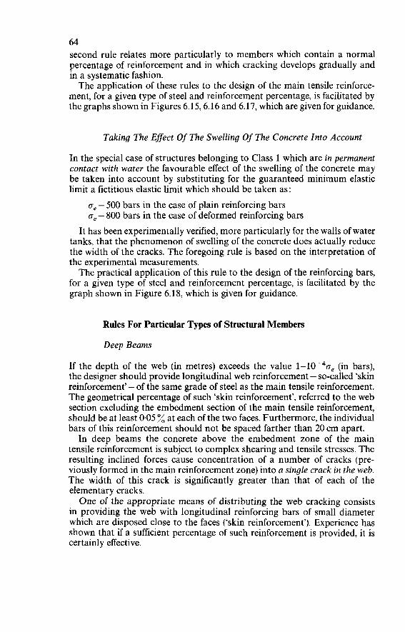
64 second rule relates more particularly to members which contain a normal percentage of reinforcement and in which cracking develops gradually and in a systematic fashion. The application of these rules to the design of the main tensile reinforce-
ment, for a given type of steel and reinforcement percentage, is facilitated by the graphs shown in Figures 6.15,6.16 and 6.17, which are given for guidance.
Taking The Effect Of The Swelling Of The Concrete Into Account
In the special case of structures belonging to Class 1 which are in permanent contact with water the favourable effect of the swelling of the concrete may be taken into account by substituting for the guaranteed minimum elastic limit a fictitious elastic limit which should be taken as:
oe - 500 bars in the case of plain reinforcing bars ge - 800 bars in the case of deformed reinforcing bars
It has been experimentally verified, more particularly for the walls of water tanks, that the phenomenon of swelling of the concrete does actually reduce the width of the cracks. The foregoing rule is based on the interpretation of the experimental measurements. The practical application of this rule to the design of the reinforcing bars,
for a given type of steel and reinforcement percentage, is facilitated by the graph shown in Figure 6.18, which is given for guidance.
Rules For Particular Types of Structural Members
Deep Beams
If the depth of the web (in metres) exceeds the value l-10-40, (in bars), the designer should provide longitudinal web reinforcement - so-called ‘skin reinforcement’ - of the same grade of steel as the main tensile reinforcement. The geometrical percentage of such ‘skin reinforcement’, referred to the web section excluding the embedment section of the main tensile reinforcement, should be at least 0.05 % at each of the two faces. Furthermore, the individual bars of this reinforcement should not be spaced farther than 20 cm apart. In deep beams the concrete above the embedment zone of the main
tensile reinforcement is subject to complex shearing and tensile stresses. The resulting inclined forces cause concentration of a number of cracks (pre- viously formed in the main reinforcement zone) into a single crack in the web. The width of this crack is significantly greater than that of each of the elementary cracks. One of the appropriate means of distributing the web cracking consists
in providing the web with longitudinal reinforcing bars of small diameter which are disposed close to the faces (‘skin reinforcement’). Experience has shown that if a sufficient percentage of such reinforcement is provided, it is certainly effective.
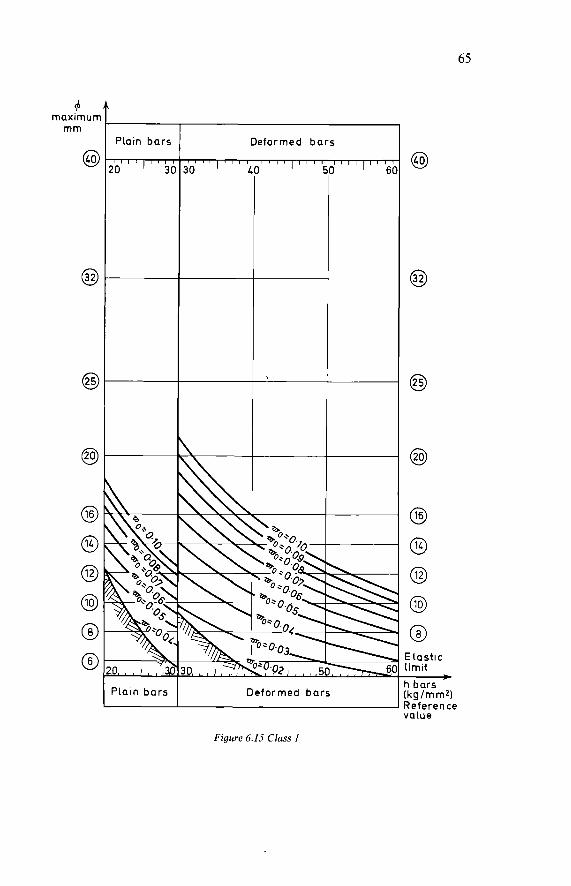
65
Plain bars Deformed bars
'Lain bars Deformed bars
Figure 6.15 Class I
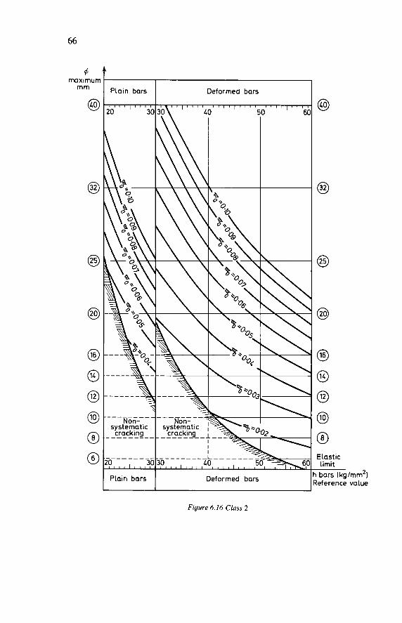
m m
@ I Plain bars I Deformed bars I
Figure 6.16 Class 2
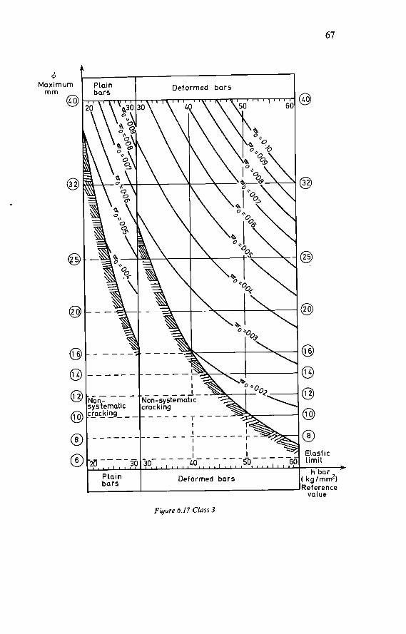
67
Figure 6.17 Class 3
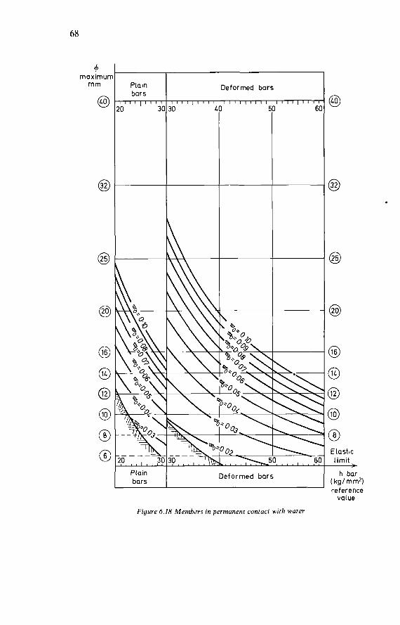
68
+ rnaxirnur
rnrn
@ Plain bars I ( I I l I
O 3(
Deformed bars
l , , , ~ , l l l I I I I ( l I 1 I I I I I I I I I I IO ! 61
Figure 6.18 Members in permanent contact with water
8
Eiastic limit
h bar í kg/rnrn2ì reference value
69 Also, the bars constituting the group of main reinforcing bars may be
distributed in a graduated fashion over a fairly substantial proportion of the bottom part of the beam. In that case it will be necessary to take the precise positions of the bars into account in calculating the lever arm of the internal forces and in the ultimate strength analysis for the beam.
Slabs And Plane Structures
In slabs and plane structures reinforced in one or in two directions and less than 30 cm thick the spacing of the individual bars of the main reinforcement should not exceed the values (which are given in centimetres) in Table 6.5.
Table 6.5
Guaranteed elastic 2000 3000 4000 5000 6000 limit of steel (I, bars bars bars bars bars
Plain round bars 20 20 20 20 20 Deformed bars 20 20 20 17.5 15 Plain drawn wires (welded fabric) 20 20 17.5 15 10
In addition, if the main reinforcement consists of welded fabric, the larger side length b of the mesh should not exceed three times the smaller side length a (hence: b d 3a). Furthermore, the average of these two dimensions [(a + b)/2] should not exceed the values given in the above table.
6.1.4 LIMIT STATE OF DEFORMATION
Fundamental Design Assumptions
Definition Of The Limit State Of Deformation
Deformations are a phenomenon specifically associated with reinforced concrete, since structural members loaded in bending, compression or tension are normally subjected to deformation under their usual conditions of service. However, for the sake of serviceability and durability of structures, it is necessary that certain deformation limits - or, more precisely, certain maximum values of the deflections-should not be exceeded. In each case, having due regard to the nature and the extent of possible damage due to deformation, these maximum values define the limit state of deformation of the member or structure considered.
Practical Calculation Of Deformations
In calculating the deformations of prismatic structural members subjected to bending and compression, it is necessary to take account as accurately
70 as possible of the various physical and mechanical phenomena that charac- terise the elasto-plastic behaviour of the concrete in compression and the cracking of the concrete in tension. In view of the uncertain and random character of many parameters, the
deformations can, with sufficient accuracy for practical purposes, be calcu- lated by means of a general method based on the three following fundamental assumptions :
1. The geometrical cross-sections of the member under consideration should first be made ‘homogeneous’ by multiplying the steel cross- sectional area by the modular ratio, i.e.,
E, B+-.A E;,
where A and B denote the steel and concrete cross-sectional areas respectively, E, denotes the modulus of elasticity of the steel (for which a value of 2 100000 bars should be adopted, cf. Section 3.1.3) and the modulus of elasticity of the concrete (for which the instantaneous modulus Ebo or the long-term modulus Eb, should be adopted, accord- ing as loads of short or long duration are involved, cf. Section 3.2.2.
2. The basic values of the tensile steel strain E, at the various sections should, for the purpose of introducing them into the conventional calculation of the deformations in the case of a member that is not entirely in compression, take account of the cracking of the concrete in tension and also allow for the corresponding effects of the bond of the main tensile reinforcement.
3. The basic values of the compressive concrete strain E; at the various sections should, for the purpose of introducing them into the conven- tional calculation of the deformations, take account of the instantaneous plasticity, the long-term plasticity and the shrinkage of the concrete.
Permissible Maximum Deflections
In the case of bridges and civil engineering structures the maximum deflections defining the limit state of deformation should be specified by the building owner. These values cannot be estimated by conventionalised general methods, for they depend directly upon the nature and the conditions of service of each particular structure. If excessive deformation is liable to endanger the stability of the structure,
the designer should also investigate the consequential effects of the deforma- tions upon the behaviour of the other elements of the structure. If need be, he should modify the arrangements thereof so as to achieve a suitable reduction of the magnitude of such deformations. This check should be made more particularly in a case where the structure may, under service conditions, be subjected to dynamic actions which can bring about a very great increase in the deflections by resonance.
71 In the case of buildings for public or private use the following maximum
values of the deflections defining the limit state of deformation may be adopted by the designer, subject to prior consent from the building owner and provided that excessive deformations can on no account endanger the overall stability of the structure or the individual stability of certain parts thereof: (a) If excessive deformations of a structural member may cause technical
damage to other, non-load-bearing, members of the structure (fragile partitions or claddings), the maximum value of the deflection under the action of the characteristic loadings (defined in Section 4.2) should be taken as one three-hundredth (1/300) of the span.
(b) If excessive deformations of a structural member may cause psycho- logical or aesthetic harm, the maximum value of the deflection under the action of the characteristic loadings (defined in Section 4.2) should be taken as one three-hundredth (1/300) of the span for service floors in buildings for public use (schools, exhibition buildings, sports halls, assembly halls, etc.) and as one hundred-and-fiftieth (1/150) of the span for service floors in buildings for private use (residential buildings). This latter value should also be adopted for the roofs (flat or sloped) for all buildings, whether for public or for private use.
General Rules For Calculation
The general calculation of deflections and deflection curves comprises the following steps : (a) establishing, for a sufficient number of sections distributed along the
member considered, the geometrical expression for the curvature as a function of the basic strains of the steel and concrete in the limit state of deformation;
(b) deducing therefrom the relationship for the variation of the curvature over the entire length of the member;
(c) determining the deflection curve by means of a double integration. The maximum ordinate of the deflection curve defines the deflection of the
member.
Cracked members
For members subjected to simple bending or composite bending which are partially in tension, and cracked, the curvature at any particular section with the abscissa x is equal to :
where (d2f)/(dx2) is the second derivative of the deflection curve with respect to the abscissa of the section considered, while E, and E; are the basic
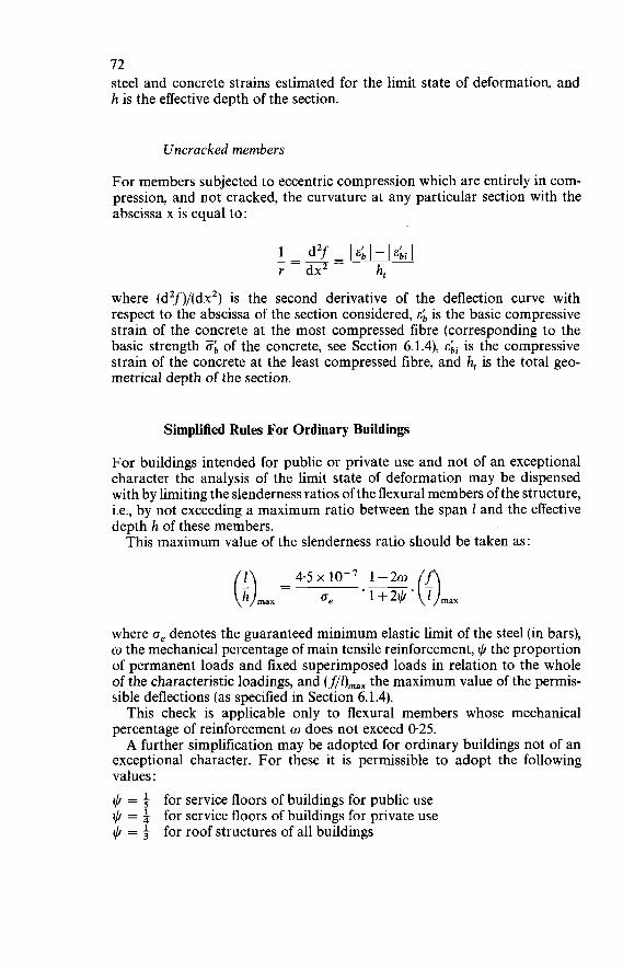
72 steel and concrete strains estimated for the limit state of deformation, and h is the effective depth of the section.
Uncracked members
For members subjected to eccentric compression which are entirely in com- pression, and not cracked, the curvature at any particular section with the abscissa x is equal to:
1 - d2f- I ~ ; l - I ~ b i l
r dx2 - ht where (d2f)/(dxZ) is the second derivative of the deflection curve with respect to the abscissa of the section considered, E; is the basic compressive strain of the concrete at the most compressed fibre (corresponding to the basic strength ob of the concrete, see Section 6.1.4), is the compressive strain of the concrete at the least compressed fibre, and h, is the total geo- metrical depth of the section.
Simplified Rules For Ordinary Buildings
For buildings intended for public or private use and not of an exceptional character the analysis of the limit state of deformation may be dispensed with by limiting the slenderness ratios of the flexural members of the structure, i.e., by not exceeding a maximum ratio between the span 1 and the effective depth h of these members. This maximum value of the slenderness ratio should be taken as:
where oe denotes the guaranteed minimum elastic limit of the steel (in bars), o the mechanical percentage of main tensile reinforcement, $ the proportion of permanent loads and Fixed superimposed loads in relation to the whole of the characteristic loadings, and (j,71)rnax the maximum value of the permis- sible deflections (as specified in Section 6.1.4). This check is applicable only to flexural members whose mechanical
percentage of reinforcement o does not exceed 0.25. A further simplification may be adopted for ordinary buildings not of an
exceptional character. For these it is permissible to adopt the following values :
$ = i for service floors of buildings for public use $ = i for service floors of buildings for private use $ = f for roof structures of all buildings
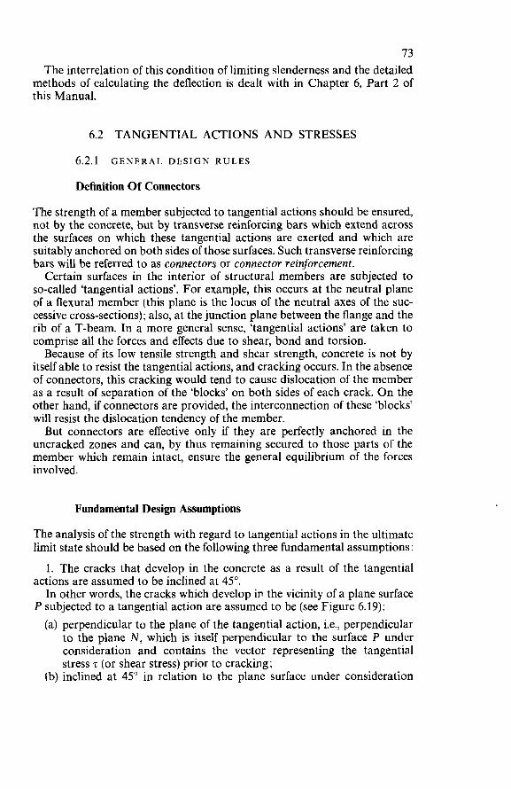
73 The interrelation of this condition of limiting slenderness and the detailed
methods of calculating the deflection is dealt with in Chapter 6, Part 2 of this Manual.
6.2 TANGENTIAL ACTIONS AND STRESSES
6.2.1 GENERAL DESIGN RULES
Definition Of Connectors
The strength of a member subjected to tangential actions should be ensured, not by the concrete, but by transverse reinforcing bars which extend across the surfaces on which these tangential actions are exerted and which are suitably anchored on both sides of those surfaces. Such transverse reinforcing bars will be referred to as connectors or connector reinforcement. Certain surfaces in the interior of structural members are subjected to
so-called ‘tangential actions’. For example, this occurs at the neutral plane of a flexural member (this plane is the locus of the neutral axes of the suc- cessive cross-sections); also, at the junction plane between the flange and the rib of a T-beam. In a more general sense, ‘tangential actions’ are taken to comprise all the forces and effects due to shear, bond and torsion. Because of its low tensile strength and shear strength, concrete is not by
itself able to resist the tangential actions, and cracking occurs. In the absence of connectors, this cracking would tend to cause dislocation of the member as a result of separation of the ‘blocks’ on both sides of each crack. O n the other hand, if connectors are provided, the interconnection of these ‘blocks’ will resist the dislocation tendency of the member. But connectors are effective only if they are perfectly anchored in the
uncracked zones and can, by thus remaining secured to those parts of the member which remain intact, ensure the general equilibrium of the forces involved.
Fundamental Design Assumptions
The analysis of the strength with regard to tangential actions in the ultimate limit state should be based on the following three fundamental assumptions :
1. The cracks that develop in the concrete as a result of the tangential actions are assumed to be inclined at 45”. In other words, the cracks which develop iri the vicinity of a plane surface
P subjected to a tangential action are assumed to be (see Figure 6.19): (a) perpendicular to the plane of the tangential action, i.e., perpendicular
to the plane N, which is itself perpendicular to the surface P under consideration and contains the vector representing the tangential stress z (or shear stress) prior to cracking;
(b) inclined at 45” in relation to the plane surface under consideration
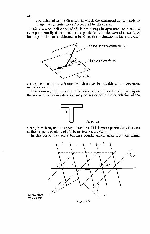
74 and oriented in the direction in which the tangential action tends to thrust the concrete 'blocks' separated by the cracks.
This assumed inclination of 45" is not always in agreement with reality, as experimentally determined, more particularly in the case of shear force loadings in the parts subjected to bending; this inclination is therefore only
an approximation - a safe one - which it may be possible to improve upon in certain cases. Furthermore, the normal components of the forces liable to act upon
the surface under consideration may be neglected in the calculation of the I I 'T
Figure 6.20
strength with regard to tangential actions. This is more particularly the case at the flange root plane of a T-beam (see Figure 6.20). In this plane may act a bending couple, which arises from the flange
Connectors 456 a-S90°
Figure 6.21
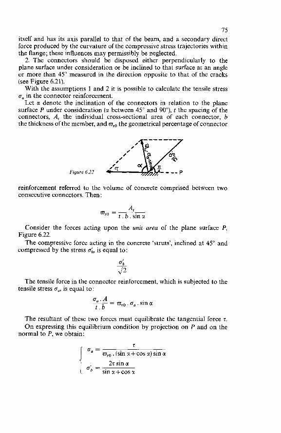
75 itself and has its axis parallel to that of the beam, and a secondary direct force produced by the curvature of the compressive stress trajectories within the flange ; these influences may permissibly be neglected. 2. The connectors should be disposed either perpendicularly to the
plane surface under consideration or be inclined to that surface at an angle or more than 45" measured in the direction opposite to that of the cracks (see Figure 6.21). With the assumptions 1 and 2 it is possible to calculate the tensile stress
on in the connector reinforcement. Let a denote the inclination of the connectors in relation to the plane
surface P under consideration (a between 45" and 90"), t the spacing of the connectors, A, the individual cross-sectional area of each connector, b the thickness of the member, and q0 the geometrical percentage of connector
reinforcement referred to the volume of concrete comprised between two consecutive connectors. Then:
At t.b.sina 'LTIto =
Consider the forces acting upon the unit area of the plane surface P,
The compressive force acting in the concrete 'struts', inclined at 45" and Figure 6.22.
compressed by the stress ob, is equal to:
The tensile force in the connector reinforcement, which is subjected to the tensile stress on, is equal to:
o,, . A t.b -- - q0. on. sin CI
The resultant of these two forces must equilibrate the tangential force 7. O n expressing this equilibrium condition by projection on P and on the
normal to P, we obtain: 7
zuto . (sin a + cos a) sin a 27 sin a
o;= . i sin a + cos a
76 If the connectors are perpendicular to P, we obtain
z
CI = 90" o;, = 22
Similarly, in the extreme case where the cracks are inclined at 45" with respect to P:
2
CI = 45" I"=- o;, = 2 These relationships are called the Rule for connector reinforcement.
3. The concrete 'struts' separated by the cracks (assuming these to be in- clined at 45" with respect to the plane considered) are assumed to be loaded in concentric compression, i.e., 'axially' loaded. The connector reinforcement (inclined at an angle of between 45" and 90" with respect to the same plane, but leaning the other way) are assumed to be loaded in concentric tension. By virtue of their interconnection the struts and the connectors form a multi- ple lattice system which should be able to equilibrate the tangential actions (lattice hypothesis). In the special case of a beam loaded by a shear force the 'lattice hypothesis'
enables the cracked beam to be treated as a multiple lattice girder whose: (a) compressive chord is formed by the compressive zone; (b) tensile chord is formed by the main tensile reinforcement; (c) web members are formed by the concrete struts in compression and
by the connector bars in tension.
6.2.2 SHEAR FORCE
Design Rule For Shear Force
The calculation of the shear strength in the ultimate limit state should be based on the three fundamental design assumptions for determining the strength with regard to tangential actions, more particularly the 'lattice hypothesis' (Section 6.2. i). However, the statistical analysis of test results shows that this hypothesis is often too conservative and that it should, in many ordinary cases, be corrected by appropriately taking into account the shear strength of the concrete in the compressive zone. Tests show that in many cases the assumption of a lattice system with
members inclined at 45" (Ritter-Mörsch theory) does not properly represent the actual behaviour of the member. The lattice hypothesis is always on the safe side, but has the drawback that.it often leads to over-design of the trans- verse reinforcement and thus to a wasteful use of steel. These are various ways to get round this difficulty and yet retain the lattice
hypothesis as the basis of design.
77 One such way is to consider the inclined concrete struts as loaded in
eccentric compression (not in concentric compression as previously assumed), which is equivalent to taking account of fixity (rigid end restraint) of the struts in the compressive zone of the member and to considering this zone as participating in resisting the shear force. Another way is to add to the resistance capacity T, of the transverse
reinforcement (as determined from the lattice hypothesis) a contribution of the concrete in the compressive zone. This is an empirical procedure,
the magnitude of Tb being based on experimentally determined data. It is this second solution that has been adopted in this Manual. With the aid of these assumptions it is possible to calculate the shear
strength of a member in the ultimate limit state. This calculation can be considered a sufficient justification of the shear strength of a structural member. Accordingly, no provision has been made for analysis of the limit states of cracking and deformation as a result of shear force.
Minimum Percentage Of Transverse Reinforcement
Every structural member which has to resist a shear force should be provided with transverse reinforcement. The mechanical percentage of such reinforce- ment should be at least two per cent (0.02), and the successive layers of bars should, in a direction parallel to the centre-line of the member, not be spaced farther apart than eighty hundredths of the effective depth of the member (t < 0.80 h). The need for providing transverse reinforcement arises from applying
the general design rule of connectors. The only possible exceptions are shells and slabs (less than 25 cm thick)
concreted in one continuous operation (see below), in which, because of their small thickness, it is not feasible to install transverse reinforcement. It should be noted that the mechanical percentage of transverse reinforce-
ment is determined by:
where Zt denotes the basic tensile strength of the transverse reinforcing steel (Section 4.3.2) and 0;I the basic compressive strength of the concrete (Section 4.3.3). The other symbols are as already defined and explained above.
Practical Design Rules
Design Of Beams And Ribs
The shear strength of beams and ribs in the ultimate limit state should be determined by adding together the resistance capacity Ta of the transverse reinforcement (calculated according to the lattice hypothesis) and the
78 resistance capacity T of the concrete in the compressive zone (calculated according to the formula in the Section on shear resistance capacity of the compressive zone below). This rule can be applied not only to the design of beam webs or the ribs
of T-beams but also to the ribs of ribbed floors (which are similar to T-beam ribs).
The shear resistance capacity T, of the transverse reinforcement should be taken as:
h . t
T, = 0.9 Z, . A, . - (sin CI + cos CI)
where Zt denotes the basic tensile strength of the transverse reinforcement (Section 4.3.2), A, the individual cross=sectional area of each layer of trans- verse reinforcement, t the spacing of the transverse reinforcement layers (measured parallel to the centre-line of the member), CI the inclination of the transverse reinforcement (in relation ;o the centre-line of the member), and h the effective depth of the section. The expression for T, presupposes that the lever arm of the internal
forces is equal to 09 h. In the case where the transverse reinforcement is perpendicular to the
centre-line of the member (e.g., vertical stirrups), the formula can be simpli- fied to:
h t
T, = 09Zt.A,.-
The shear resistance capacity & of the concrete in the compressive zone is allowed to be taken into account only on condition that no direct (normal) tensile force acts upon the section considered and that the bending moment M at that section is at least equal to 1.5 Th. The first condition rules out the possibility of taking the contribution of
the concrete into account in the case of a member subjected to bending in combination with tension. The design of such a member should be based on the direct application of the fundamental design assumptions for con- nectors (Section 6.2.1, rule for connector reinforcement). It can be shown that those assumptions can indeed legitimately be applied to loadings consisting of shear with tension as well as to those consisting of shear with compression. The second condition excludes the zones in the vicinity of the supports.
These zones should, in each case, be specially investigated (see section below on design of slabs and shells); in particular, the mode of transmission of the forces should be checked and, if need be, constructional modifications should be made to ensure that this transmission is efficiently effected. The shear resistance capacity T varies between a minimum of i. o b . bo. h
and a maximum of
79 Hence :
where the compressive direct force N (if any) is expressed in bars. If the member is ‘over-reinforced, i.e., if the longitudinal tensile reinforce-
ment is able, in the ultimate limit state, to resist a fictitious moment I M I + 1.5 I TI h-0.5 1 N’ I h (where the bending moment M, the shear force T, and the direct compressive force N are expressed in absolute values), the shear resistance capacity & of the concrete in the compressive zone should be taken as :
subject to the following limiting condition:
O bo ~ ~ 2 0 . 0 5 . f. - Ob
where w denotes the mechanical percentage of longitudinal tensile re- inforcement (fully anchored beyond the section considered), w p the mech- anical percentage of longitudinal tensile reinforcement strictly necessary to resist the fictitious moment 1 M I + 1.5 I TI h-0.5 1 N 1 h, b the width of the compressive zone of the beam (or the effective width of the compressive flange of a T-beam or ribbed floor), b, the width of the web (in the case of a beam) or the rib (in the case of a T-beam or ribbed floor), O, the basic tensile strength of the longitudinal tensile reinforcement, ob the basic compressive strength of the concrete, and Ob the basic tensile strength of the concrete.
If the longitudinal tensile reinforcement is not able, in the ultimate limit state, to resist a fictitious moment 1 M I + 1.5 1 TI h-0.5 I N 1 h, the shear resistance capacity & of the concrete in the compressive zone should be taken as:
3 - 8
interpretation of existing test results.
& = -.ob. bo. h These values and these limits have been deduced from the statistical
They are applicable to all cases of bending combined with compression. For simple bending (N = O) the design formulae become much simpler;
of the concrete in the compressive zone is in this
The total resistance capacity for shear force in the ultimate limit state
the resistance capacitity case comprised between the following limits :
should be taken as
for beams and ribs. This must, however, be limited to a maximum value of
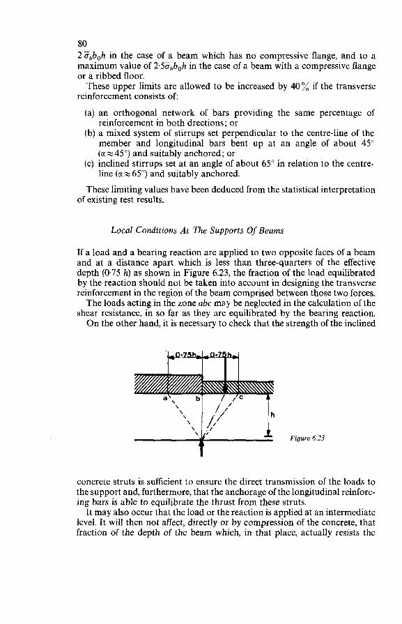
80 2¿fbb0h in the case of a beam which has no compressive flange, and to a maximum value of 2.5ó,b0h in the case of a beam with a compressive flange or a ribbed floor. These upper limits are allowed to be increased by 40% if the transverse
reinforcement consists of:
(a) an orthogonal network of bars providing the same percentage of reinforcement in both drections; or
(b) a mixed system of stirrups set perpendicular to the centre-line of the member and longitudinal bars bent up at an angle of about 45" (cr=45") and suitably anchored; or
(c) inclined stirrups set at an angle of about 65" in relation to the centre- line (a N 65") and suitably anchored.
These limiting values have been deduced from the statistical interpretation of existing test results.
Local Conditions At The Supports Of Beams
If a load and a bearing reaction are applied to two opposite faces of a beam and at a distance apart which is less than three-quarters of the effective depth (0.75 h) as shown in Figure 6.23, the fraction of the load equilibrated by the reaction should not be taken into account in designing the transverse reinforcement in the region of the beam comprised between those two forces. The loads acting in the zone abc may be neglected in the calculation of the
shear resistance, in so far as they are equilibrated by the bearing reaction. O n the other hand, it is necessary to check that the strength of the inclined
Figure 6.23
concrete struts is sufficient to ensure the direct transmission of the loads to the support and, furthermore, that the anchorage of the longitudinal reinforc- ing bars is able to equilibrate the thrust from these struts. It may also occur that the load or the reaction is applied at an intermediate
level. It will then not affect, directly or by compression of the concrete, that fraction of the depth of the beam which, in that place, actually resists the
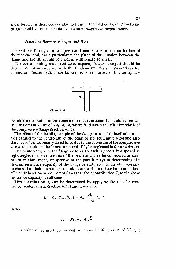
81 shear force. It is therefore essential to transfer the load or the reaction to the proper level by means of suitably anchored suspension reinforcement.
Junctions Between Flanges And Ribs
The sections through the compressive flange parallel to the centre-line of the member and, more particularly, the plane of the junction between the flange and the rib should be checked with regard to shear. The corresponding shear resistance capacity (shear strength) should be
determined in accordance with the fundamental design assumptions for connectors (Section 6.2.1, rule for
Figure 6.24
connector reinforcement), ignoring any
I
possible contribution of the concrete to that resistance. It should be limited to a maximum value of 3 Ob. be. h, where be denotes the effective width of the compressive flange (Section 6.1.1). The effect of the bending couple of the flange or top slab itself (about an
axis parallel to the centre-line of the beam or rib, see Figure 6.24) and also the effect of the secondary direct force due to the curvature of the compressive stress trajectories in the flange can permissibly be neglected in the calculation. The reinforcement of the flange or top slab itself is generally disposed at
right angles to the centre-line of the beam and may be considered as con- nector reinforcement, irrespective of the part it plays in determining the flexural resistance capacity of the flange or slab. So it is merely necessary to check that their anchorage conditions are such that these bars can indeed efficiently function as ‘connectors’ and that their contribution T, to the shear resistance capacity is sufficient. This contribution T, can be determined by applying the rule for con-
nector reinforcement (Section 6.2.1) and is equal to:
.be.z T,=O,.~D~~.~,.Z=CT,.- - A* t . be
hence :
h T, = 0.9.¿7,.At.- t
This value of T, must not exceed an upper limiting value of 3 ¿fbbeh;
82 hence :
h T = T, = 0.9. O,. A, .- < 3 . ab. be. h t
It should then be checked that this shear resistance capacity is sufficient.
Design Of Slabs And Shells
Notwithstanding the stipu1,ation of a minimum percentage of transverse reinforcement in any member subjected to shear force, transverse reinforce- ment may be omitted in slabs and shells, provided that the following con- ditions are satisfied : (a) The structural behaviour really is that of a slab or shell.
In other words, if a loading tends to produce a shear crack, the strength in bending should, in the direction perpendicular to that crack, prevent it from opening out.
(b) At each point the ratio of the bending moments of the same algebraic sign acting upon two mutually perpendicular sections - i.e., the ratio of the moments producing curvatures of the same sign in two mutually perpendicular directions - should, in the ultimate limit state, be at least equal to four.
(c) Concreting should be performed as a continuous operation, without any construction joints in the direction of the thickness of the slab or shell.
Subject to fulfilment of these conditions, the shear resistance capacity of slabs and shells in the ultimate limit state should be taken as equal to 0.8 Sb . h per unit width.
6.2.3 BOND
Definition O f Bond
The notion of 'bond' comprises two distinct functions : anchorage bond and flexural bond.
Anchorage bond: At each end of a reinforcing bar the axial tensile or compressive force applied to the bar has to be transmitted to the concrete by bond. This bond at the ends constitutes bond by anchorage.
Flexural bond: This form of bond occurs in all intermediate parts of the bar (i.e., other than at the ends) and equilibrates the variations in the axial tensile or compressive force applied to the bar.
Anchorage O f Reinforcing Bars
Basic Principles Of Anchorage Calculations
The anchorage should be checked for the ultimate limit state; the check should be applied to each bar, considered individually, even if that bar belongs to a group of bars.
83 This check should be based on the three following fundamental assump-
(a) over the entire anchorage length of the bar the bond stress is constant and equal to its limit value ?d;
(b) in the curved parts of an anchorage a frictional force acts in addition to the bond as envisaged in (a); this frictional force should be taken as equal to the curvature reaction of the bar (which for this purpose is conceived as a wire wrapped round a cylinder) multiplied by the co- efficient of friction between steel and concrete ;
(c) the anchorage of the reinforcement is considered to be ‘total’ if, in the ultimate limit state, the tensile force A. Fa in the bar under considera- tion is equilibrated by the bond and frictional forces.
In the vicinity of the reinforcement the bond should be conceived as a tangential action that can produce cracking at 45” in the covering concrete. But the ‘struts’ separated by the inclined cracks thus formed are only able to equilibrate the compressive forces. Therefore, in order to equilibrate the corresponding tensile components, it is necessary to provide transverse connectors, so-called fastening connectors. These are essential to the effi- ciency of the anchorage. The fastening connectors should surround the bar to be anchored (or the
corresponding group of bars); they should pass round the ‘outside’ of the bar (or bars), i.e., on the side nearest the exterior of the member, and should be suitably anchored in the interior of the concrete. Let Td denote the bond stress in the ultimate limit state, Zf the basic
strength of the connector reinforcement, A, the total cross-sectional area of the connector reinforcement, and p the perimeter of the bar to be anchored. Consider the equilibrium condition :
p.t.Td=At.Zt
tions :
i.e. :
Transverse reinforcement already provided for a different purpose, e.g., to resist shear force, may be considered to function as fastening connectors for the main tensile reinforcing bars at the points of curtailment or division of those bars. However, it should be checked that such transverse reinforcement is indeed sufficient for the purpose; otherwise it will have to be augmented. Thin members (slabs and shells) present special problems, since it is not
possible, on account of their limited depth, to provide them with fastening connectors. In such cases the designer will have to furnish special justifica- tion of the efficiency of the anchorages.
Straight Anchorage
Over the anchorage length the limit value of the bond stress is assumed to be constant and should be taken as:
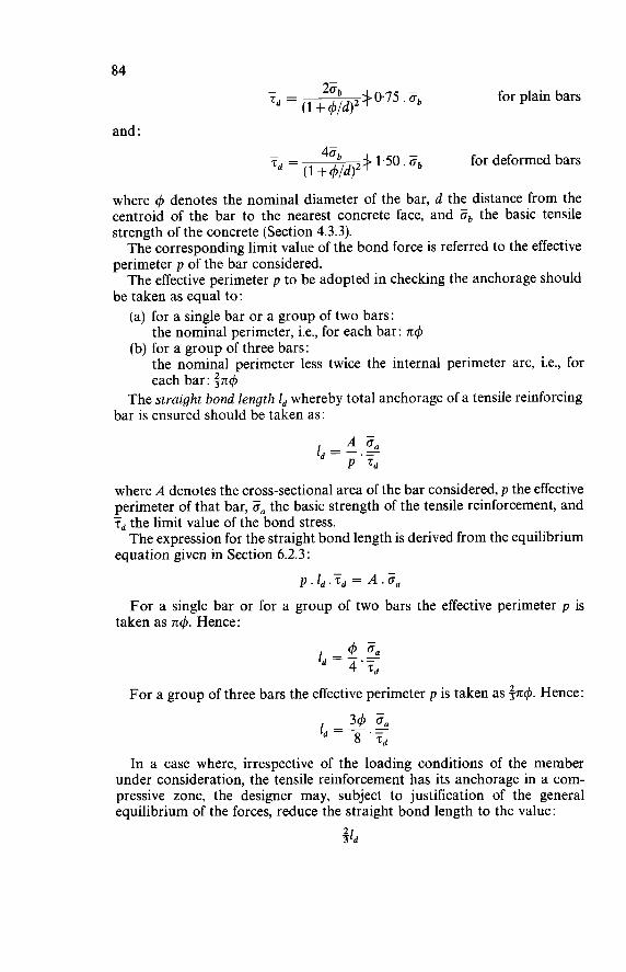
84
and :
for plain bars
for deformed bars
where 4 denotes the nominal diameter of the bar, d the distance from the centroid of the bar to the nearest concrete face, and Ob the basic tensile strength of the concrete (Section 4.3.3). The corresponding limit value of the bond force is referred to the effective
perimeter p of the bar considered. The effective perimeter p to be adopted in checking the anchorage should
be taken as equal to: (a) for a single bar or a group of two bars:
(b) for a group of three bars: the nominal perimeter, i.e., for each bar: n$
the nominal perimeter less twice the internal perimeter arc, i.e., for each bar: $nd
The straight bond length 1, whereby total anchorage of a tensile reinforcing bar is ensured should be taken as:
where A denotes the cross-sectional area of the bar considered, p the effective perimeter of that bar, O, the basic strength of the tensile reinforcement, and z, the limit value of the bond stress. The expression for the straight bond length is derived from the equilibrium
equation given in Section 6.2.3:
-
For a single bar or for a group of two bars the effective perimeter p is taken as n4. Hence:
For a group of three bars the effective perimeter p is taken as 5.4. Hence:
In a case where, irrespective of the loading conditions of the member under consideration, the tensile reinforcement has its anchorage in a com- pressive zone, the designer may, subject to justification of the general equilibrium of the forces, reduce the straight bond length to the value:
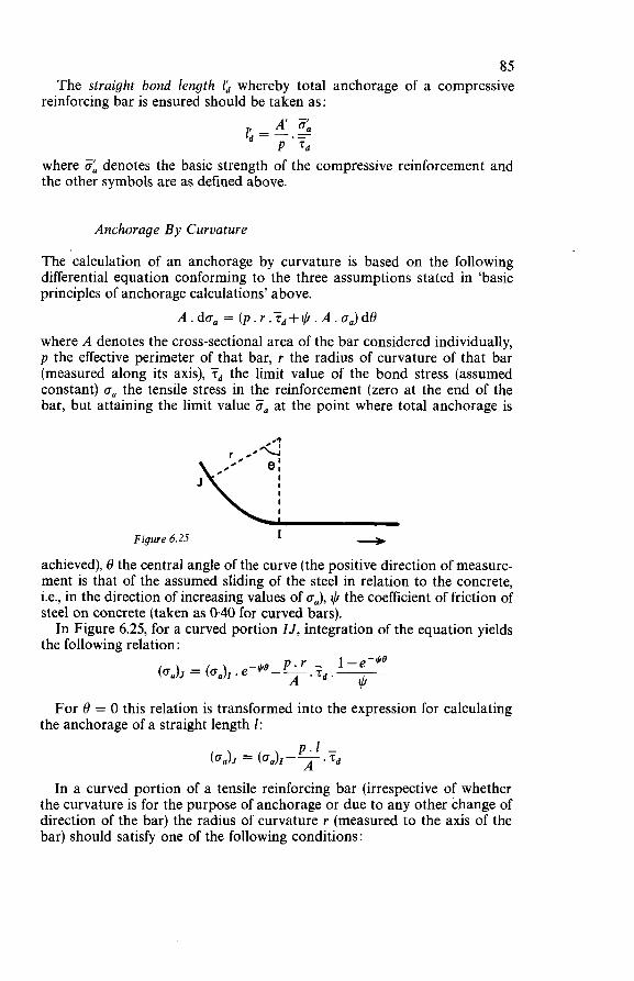
85 The straight bond length Id whereby total anchorage of a compressive
reinforcing bar is ensured should be taken as: A' 3, 1'-- -
d - P'Td where 5 denotes the basic strength of the compressive reinforcement and the other symbols are as defined above.
Anchorage By Curvature
The calculation of an anchorage by curvature is based on the following differential equation conforming to the three assumptions stated in 'basic principies of anchorage calculations' above.
A.da, = (p.r.Td+iI/.A.o,)d8 where A denotes the cross-sectional area of the bar considered individually, p the effective perimeter of that bar, r the radius of curvature of that bar (measured along its axis), Td the limit value of the bond stress (assumed constant) a, the tensile stress in the reinforcement (zero at the end of the bar, but attaining the limit value Z, at the point where total anchorage is
+ Figure 6.25 I
achieved), 8 the central angle of the curve (the positive direction of measure- ment is that of the assumed sliding of the steel in relation to the concrete, i.e., in the direction of increasing values of o=), the coefficient of friction of steel on concrete (taken as 0.40 for curved bars). In Figure 6.25, for a curved portion IJ, integration of the equation yields
the following relation:
For 8 = O this relation is transformed into the expression for calculating the anchorage of a straight length 1:
In a curved portion of a tensile reinforcing bar (irrespective of whether the curvature is for the purpose of anchorage or due to any other change of direction of the bar) the radius of curvature r (measured to the axis of the bar) should satisfy one of the following conditions:
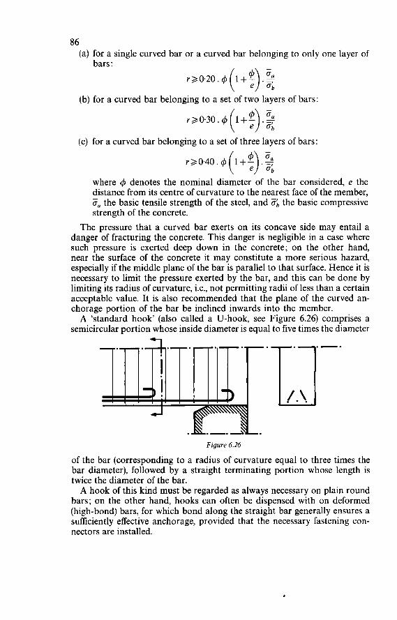
86 (a) for a single curved bar or a curved bar belonging to only one layer of
bars : r20.20. 4 (1+;). 5
(b) for a curved bar belonging to a set of two layers of bars:
(c) for a curved bar belonging to a set of three layers of bars:
where 4 denotes the nominal diameter of the bar considered, e the distance from its centre of curvature to the nearest face of the member, O, the basic tensile strength of the steel, and O;, the basic compressive strength of the concrete.
The pressure that a curved bar exerts on its concave side may entail a danger of fracturing the concrete. This danger is negligible in a case where such pressure is exerted deep down in the concrete; on the other hand, near the surface of the concrete it may constitute a more serious hazard, especially if the middle plane of the bar is parallel to that surface. Hence it is necessary to limit the pressure exerted by the bar, and this can be done by limiting its radius of curvature, i.e., not permitting radii of less than a certain acceptable value. It is also recommended that the plane of the curved an- chorage portion of the bar be inclined inwards into the member. A ‘standard hook’ (also called a U-hook, see Figure 6.26) comprises a
semicircular portion whose inside diameter is equal to five times the diameter
Figure 6.26
of the bar (corresponding to a radius of curvature equal to three times the bar diameter), followed by a straight terminating portion whose length is twice the diameter of the bar. A hook of this kind must be regarded as always necessary on plain round
bars; on the other hand, hooks can often be dispensed with on deformed (high-bond) bars, for which bond along the straight bar generally ensures a sufficiently effective anchorage, provided that the necessary fastening con- nectors are installed.
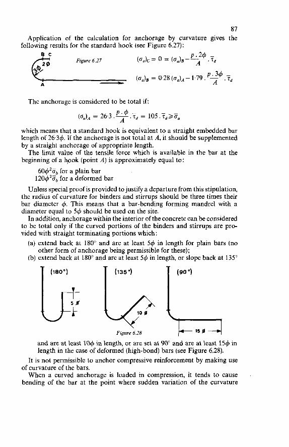
87 Application of the calculation for anchorage by curvature gives the
following results for the standard hook (see Figure 6.27):
The anchorage is considered to be total if:
which means that a standard hook is equivalent to a straight embedded bar length of 26.34. If the anchorage is not total at A, it should be supplemented by a straight anchorage of appropriate length. The limit value of the tensile force which is available in the bar at the
beginning of a hpok (point A) is approximately equal to : 60420b for a plain bar 120q520b for a deformed bar
Unless special proof is provided to justify a departure from this stipulation, the radius of curvature for binders and stirrups should be three times their bar diameter q5. This means that a bar-bending forming mandrel with a diameter equal to 54 should be used on the site. In addition, anchorage within the interior of the concrete can be considered
to be total only if the curved portions of the binders and stirrups are pro- vided with straight terminating portions which: (a) extend back at 180" and are at least 54 in length for plain bars (no (b) extend back at 180" and are at least 54 in length, or slope back at 135"
other form of anchorage being permissible for these);
I I 5 Ø I
Figure 6.28
and are at least 104 in length, or are set at 90" and are at least i54 in length in the case of deformed (high-bond) bars (see Figure 6.28).
It is not permissible to anchor compressive reinforcement by making use of curvature of the bars. When a curved anchorage is loaded in compression, it tends to cause
bending of the bar at the point where sudden variation of the curvature
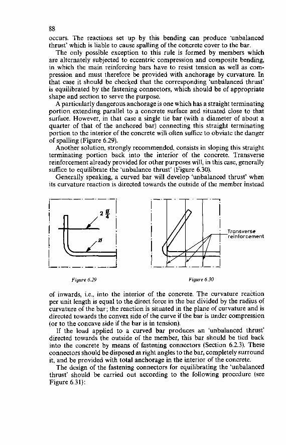
88 occurs. The reactions set up by this bending can produce ‘unbalanced thrust’ which is liable to cause spalling of the concrete cover to the bar. The only possible exception to this rule is formed by members which
are alternately subjected to eccentric compression and composite bending, in which the main reinforcing bars have to resist tension as well as com- pression and must therefore be provided with anchorage by curvature. In that case it should be checked that the corresponding ‘unbalanced thrust’ is equilibrated by the fastening connectors, which should be of appropriate shape and section to serve the purpose. A particularly dangerous anchorage is one which has a straight terminating
portion extending parallel to a concrete surface and situated close to that surface. However, in that case a single tie bar (with a diameter of about a quarter of that of the anchored bar) connecting this straight terminating portion to the interior of the concrete will often suffice to obviate the danger of spalling (Figure 6.29). Another solution, strongly recommended, consists in sloping this straight
terminating portion back into the interlor of the concrete. Transverse reinforcement already provided for other purposes will, in this case, generally suffice to equilibrate the ‘unbalance thrust’ (Figure 6.30). Generally speaking, a curved bar will develop ‘unbalanced thrust’ when
its curvature reaction is directed towards the outside of the member instead
!-.-.___._.i Figure 6.29 Figure 6.30
of inwards, i.e., into the interior of the concrete. The curvature reaction per unit length is equal to the direct force in the bar divided by the radius of curvature of the bar; the reaction is situated in the plane of curvature and is directed towards the convex side of the curve if the bar is under compression (or to the concave side if the bar is in tension).
If the load applied to a curved bar produces an ‘unbalanced thrust’ directed towards the outside of the member, this bar should be tied back into the concrete by means of fastening connectors (Section 6.2.3). These connectors should be disposed at right angles to the bar, completely surround it, and be provided with total anchorage in the interior of the concrete. The design of the fastening connectors for equilibrating the ‘unbalanced
thrust’ should be carried out according to the following procedure (see Figure 6.31):
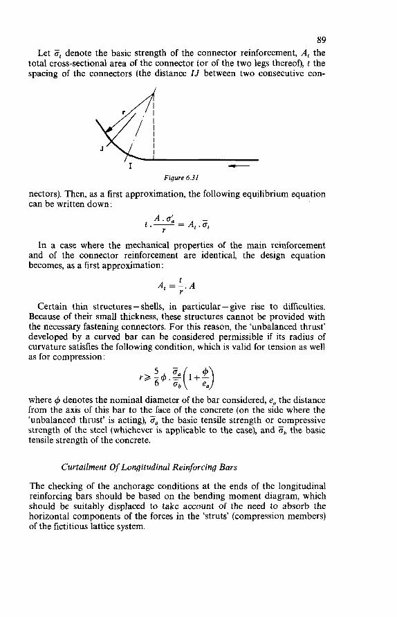
89 Let Ft denote the basic strength of the connector reinforcement, A, the
total cross-sectional area of the connector (or of the two legs thereof), t the spacing of the Connectors (the distance IJ between two consecutive con-
Figure 6.31
nectors). Then, as a first approximation, the following equilibrium equation can be written down:
A . IJ; r t.- = A,. Ft
In a case where the mechanical properties of the main reinforcement and of the connector reinforcement are identical, the design equation becomes, as a first approximation:
t r
A, =-.A
Certain thin structures - shells, in particular - give rise to difficulties. Because of their small thickness, these structures cannot be provided with the necessary fastening connectors. For this reason, the ‘unbalanced thrust’ developed by a curved bar can be considered permissible if its radius of curvature satisfies the following condition, which is valid for tension as well as for compression:
where 4 denotes the nominal diameter of the bar considered, ea the distance from the axis of this bar to the face of the concrete (on the side where the ‘unbalanced thrust’ is acting), 0, the basic tensile strength or compressive strength of the steel (whichever is applicable to the case), and Ob the basic tensile strength of the concrete.
Curtailment Of Longitudinal Reinforcing Bars
The checking of the anchorage conditions at the ends of the longitudinal reinforcing bars should be based on the bending moment diagram, which should be suitably displaced to take account of the need to absorb the horizontal components of the forces in the ‘struts’ (compression members) of the fictitious lattice system.
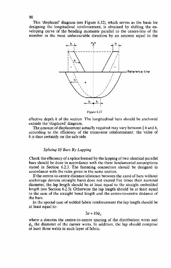
90 This ‘displaced’ diagram (see Figure 6.32), which serves as the basis for
designing the longitudinal reinforcement, is obtained by shifting the en- veloping curve of the bending moments parallel to the centre-line of the member in the most unfavourable direction by an amount equal to the
,Reference line
Figure 6.32
effective depth h of the section. The longitudinal bars should be anchored outside the ‘displaced’ diagram. The amount of displacement actually required may vary between h and h,
according to the efficiency of the transverse reinforcement: the value of h is thus certainly on the safe side.
Splicing Of Bars B y Lapping
Check the efficiency of a splice formed by the lapping of two identical parallel bars should be done in accordance with the three fundamental assumptions stated in Section 6.2.3. The fastening connectors should be designed in accordance with the rules given in the same section. If the centre-to-centre distance (distance between the axes) of bars without
anchorage devices (straight bars) does not exceed five times their nominal diameter, the lap length should be at least equal to the straight embedded length (see Section 6.2.3). Otherwise the lap length should be at least equal to the sum of the straight bond length and the centre-to-centre distance of the bars. In the special case of welded fabric reinforcement the lap length should be
at least equal to: 2a + 1040
where a denotes the centre-to-centre spacing of the distribution wires and q5a the diameter of the carrier wires. In addition, the lap should comprise at least three welds in each layer of fabric.
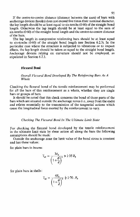
91 If the centre-to-centre distance (distance between the axes) of bars with
anchorage devices (hooks) does not exceed five times their nominal diameter, the lap length should be at least equal to six-tenths (0.60) of the straight bond length. Otherwise the lap length should be at least equal to the sum of six-tenths (0.60) of the straight bond length and the centre-to-centre distance of the bars. The lap length in compressive reinforcing bars should be at least equal
to six-tenths (0.60) of the straight bond length (see Section 6.2.3). In the particular case where the structure is subjected to vibrations or to impact effects, the lap length should be taken as equal to the straight bond length. Anchorage devices relying on curvature should not be employed, as stipulated in Section 6.2.3.
Flexural Bond
Overall Flexural Bond Developed By The Reinforcing Bars As A Whole
Checking the flexural bond of the tensile reinforcement may be performed for all the bars of this reinforcement as a whole, whether they are single bars or groups of bars. It should be noted that this check concerns the bond of those parts of the
bars which are situated outside the anchorage zones (i.e., away from the ends) and relates essentially to the transmission of the tangential actions which cause the longitudinal force exerted by the reinforcement to vary.
Checking The Flexural Bond In The Ultimate Limit State
For checking the flexural bond developed by the tensile reinforcement in the ultimate limit state by shear action all along the bars the following assumptions should be made : Outside the anchorage zone the limit value of the bond stress is constant
and has these values: for plain bars in beams:
for plain bars in shells:
92 for deformed bars :
where 4 denotes the nominal bar diameter and d the distance from the axis of the bar to the nearest face of the concrete. The corresponding limit value of the bond force is referred to the effective
perimeter p of the bar or of the group of bars considered. The effective perimeter p to be introduced into the check calculation for
flexural bond should be taken as: (a) the nominal perimeter in the case of a single bar, i.e., 7c4; (b) the minimum circumscribed perimeter of the cross-section in the case
of a group of two bars, i.e., (7c + 2)4; (c) the nominal circumscribed perimeter of the cross-section less the
perimeter of the space enclosed in the case of a group of three bars, i.e., (3. + 3)4.
The flexural bond of the reinforcement is effective if, in the ultimate limit state, the shear force is equilibrated by the bond forces of all the bars of which this reinforcement is composed. For an elementary length dx of the reinforcement the equilibrium equation
is expressed by the relation: A.dZa = n.p.ïd,
where n denotes the number of bars comprised in the reinforcement with a total cross-sectional area A. On introducing the shear force T, the lever arm z and the effective depth
h of the section, this equilibrium equation can be written as follows:
or:
6.2.4 TORSION
Basis For The Calculation Of Torsional Strength
The calculation for determining the torsional strength in the ultimate limit state should be based on the ‘lattice hypothesis’ (Section 6.2.1). Analysis of test results has shown, however, that the lattice hypothesis is often too con- servative and that it should be corrected by appropriately taking into account the torsional strength of the concrete in the compressive zone.
Tests have shown that in many cases the lattice hypothesis, which is on the safe side, has the drawback that it results in wasteful over-designing of the torsion reinforcement.
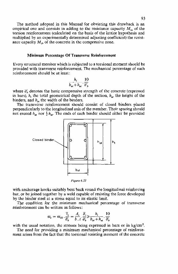
93 The method adopted in this Manual for obviating this drawback is an
empirical one and consists in adding to the resistance capacity M,, of the torsion reinforcement (calculated on the basis of the lattice hypothesis and multiplied by an experimentally determined adjusting coefficient) the resist- ance capacity M,b of the concrete in the compressive zone.
Minimum Percentage O f Transverse Reinforcement
Every structural member which is subjected to a torsional moment should be provided with transverse reinforcement. The mechanical percentage of such reinforcement should be at least:
h, 10 b,, + hat ' ob
where Ob denotes the basic compressive strength of the concrete (expressed in bars), h, the total geometrical depth of the section, ha, the height of the binders, and bat the width of the binders. The transverse reinforcement should consist of closed binders placed
perpendicularly to the longitudinal axis of the member. Their spacing should not exceed b,, nor i ha,. The ends of each binder should either be provided
~-
\ Closed binder
Figure 6.33
with anchorage hooks suitably bent back round the longitudinal reinforcing bar, or be joined together by a weld capable of resisting the force developed by the binder steel at a stress equal to its elastic limit. The condition for the minimum mechanical percentage of transverse
reinforcement can be written as follows :
with the usual notation, the stresses being expressed in bars or in kg/cm2. The need for providing a minimum mechanical percentage of reinforce-
ment arises from the fact that the torsional resisting moment of the concrete
94 in the compressive zone is much lower than the torsional moment corre- sponding to the development of inclined cracks. So, in order to ensure that the total torsional resisting moment will exceed the torsional moment corre- sponding to cracking, a sufficient percentage of transverse torsion reinforce- ment must be provided. This condition obviates the dangerous possibility of brittle fracture occurring suddenly and without warning signs (see Figure 6.33). In a structural member loaded in torsion the inclined cracks are liable
to appear on all the faces. For this reason it is essential to provide closed binders, so as to have connector reinforcement across all cracks that will possibly develop. It is for this same reason, too, that the minimum spacing (t ,< bat and t ,<+hat) has been laid down for the binders.
Practical Design Rules
The torsional resistance capacity (torsional strength) of structural members in the ultimate limit state should be determined by adding the contribution M,, of the transverse reinforcement (calculated according to the lattice hypothesis, Section 6.2.1) and the contribution Mtb of the concrete in the compressive zone (calculated from the empirical formula given below).
Contribution Of The Transverse Reinforcement To The Torsional Strength
The contribution M,, of the transverse reinforcement to the torsional strength of a structural member is :
A t M,, = CI. at. L. bat. hat
where :
u is a coefficient equal to 0.33 +0.16 !k but not exceeding 0.75;
O, is the basic tensile strength of the transverse reinforcing steel, subject to an upper limit of 2 500 bars;
A, is the total cross-sectional area of the two legs of a binder; t is the spacing of the binders (measured parallel to the centre-line of the
member) ; bat is the width of the binders; ha, is the height of the binders. The expression for M,, conforms to the application of the ‘lattice hypo-
thesis’ in conjunction with the introduction of a reduction coefficient u which is justified by the results of tests carried out in the Laboratories of the Portland Cement Association, Illinois, U.S.A.
bat
95 The torsional reinforcement should not consist solely of transverse binders.
There should, in addition, always be a longitudinal reinforcement with a total cross-sectional area:
A AT = bat. hat
This longitudinal reinforcement should comprise at least four bars placed respectively at the four corners of the transverse binders. But if hat > 2bat, then it should also comprise longitudinal bars at the longer sides of the binders; these bars should not be spaced farther apart than $bat. Besides, the diameter of the longitudinal reinforcing bars should be at least equal to the diameter of the binder reinforcement and not less than 10 mm. The transverse binders and the corresponding longitudinal bars together
form the torsion reinforcement. For the ‘lattice’ mechanism’to be effective, the reactions from the concrete
‘struts’ separated by the torsional cracks should be equilibrated in the trans- verse and in the longitudinal direction. Hence the need for both longitudinal and transverse reinforcement. This double system of ‘torsion reinforcement’ is additional to the reinforce-
ment required for giving the member its strength to resist bending (longi- tudinal flexural reinforcement, cf. Section 6.1) and to resist shear force (transverse shear reinforcement, cf. Section 6.2.2). The longitudinal reinforcing bars should be distributed as uniformly
as possible around the perimeter of the transverse binders, in order to en- sure efficient arrangement of connector reinforcement across the torsional cracks.
Contribution Of The Concrete In The Compressive Zone T o The Torsional Strength
The contribution kf,, of the concrete in the compressive zone to the torsional strength of a structural member can be taken into account only on con- dition that no direct tensile force acts upon the section considered. This contribution should be taken as:
M,, = B.Zb.J! h,-J! b2( 4 3)
where : fl is a reduction coefficient equal to
1
J { 1 + [ 1.3.: (h, - 2) . $1 ’}
T is the total shear force (Section 6.2.2) taken into account in checking the ultimate limit state ( T = T, + TJ;
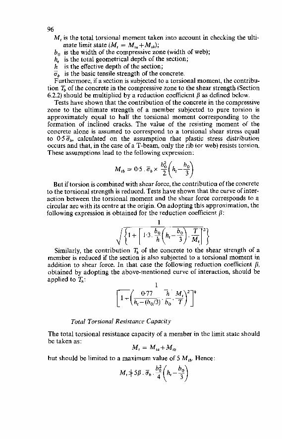
96 M, is the total torsional moment taken into account in checking the ulti-
mate limit state (MI = MI, + Mth); bo is the width of the compressive zone (width of web); h, is the total geometrical depth of the section; h is the effective depth of the section; ob is the basic tensile strength of the concrete. Furthermore, if a section is subjected to a torsional moment, the contribu-
tion q of the concrete in the compressive zone to the shear strength (Section 6.2.2) should be multiplied by a reduction coefficient ß as defined below. Tests have shown that the contribution of the concrete in the compressive
zone to the ultimate strength of a member subjected to pure torsion is approximately equal to half the torsional moment corresponding to the formation of inclined cracks. The value of the resisting moment of the concrete alone is assumed to correspond to a torsional shear stress equal to 0.5 ab, calculated on the assumption that plastic stress distribution occurs and that, in the case of a T-beam, only the rib (or web) resists torsion. These assumptions lead to the following expression :
-
Mtb = 0.5. ab x 2 h,-O b2( 2 ,)
But if torsion is combined with shear force, the contribution of the concrete to the torsional strength is reduced. Tests have shown that the curve of inter- action between the torsional moment and the shear force corresponds to a circular arc with its centre at the origin. On adopting this approximation, the following expression is obtained for the reduction coefficient ß:
1
Similarly, the contribution q of the concrete to the shear strength of a member is reduced if the section is also subjected to a torsional moment in addition to shear force. In that case the following reduction coefficient fi, obtained by adopting the above-mentioned curve of interaction, should be applied to G:
1 r-41 h M , 2 3 ht - ' bo
Total Torsional Resistance Capacity
The total torsional resistance capacity of a member in the limit state should be taken as:
but should be limited to a maximum value of 5 Mtb. Hence: =
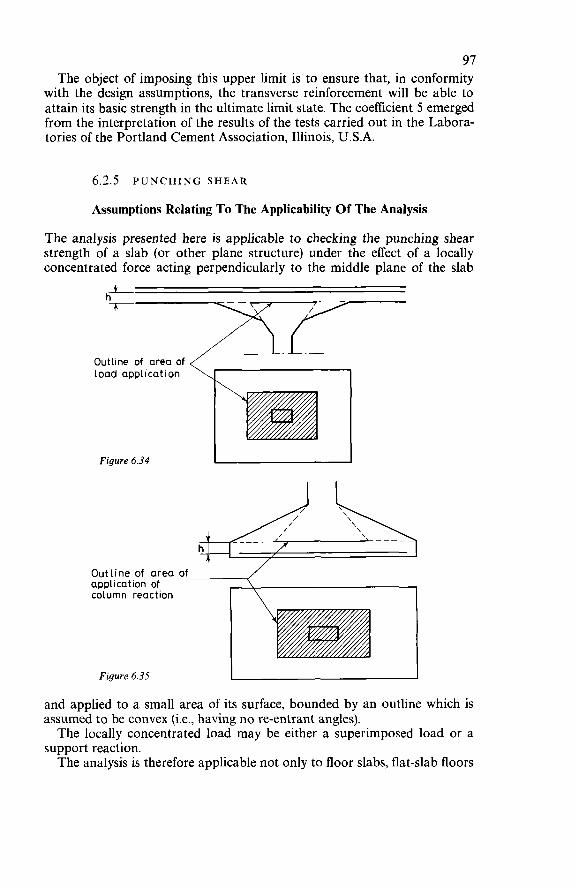
97 The object of imposing this upper limit is to ensure that, in conformity
with the design assumptions, the transverse reinforcement will be able to attain its basic strength in the ultimate limit state. The coefficient 5 emerged from the interpretation of the results of the tests carried out in the Labora- tories of the Portland Cement Association, Illinois, U.S.A.
6.2.5 PUNCHING S H E A R
Assumptions Relating To The Applicability Of The Analysis
The analysis presented here is applicable to checking the punching shear strength of a slab (or other plane structure) under the effect of a locally concentrated force acting perpendicularly to the middle plane of the slab
Outline of area of load application
Figure 6.34
Outline of area of application of column reaction
Figure 6.35 - and applied to a small area of its surface, bounded by an outline which is assumed to be convex (i.e., having no re-entrant angles). The locally concentrated load may be either a superimposed load or a
support reaction. The analysis is therefore applicable not only to floor slabs, flat-slab floors
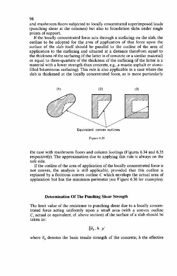
98 and mushroom floors subjected to locally concentrated superimposed loads (punching shear at the columns) but also to foundation slabs under single points of support.
If the locally concentrated force acts through a surfaciqg on the slab, the outline to be adopted for the area of application of that force upon the surface of the slab itself should be parallel to the outline of the area of application to the surfacing and situated at a distance therefrom equal to the thickness of the surfacing (if the latter is of concrete or a similar material) or equal to three-quarters of the thickness of the surfacing (if the latter is a material with a lower strength than concrete, e.g., a mastic asphalt or stone- filled bituminous surfacing). This rule is also applicable in a case where the slab is thickened at the locally concentrated force, as is more particularly
Equivalent convex outlines
Figure 6.36
the case with mushroom floors and column footings (Figures 6.34 and 6.35 respectively). The approximation due to applying this rule is always on the safe side.
If the outline of the area of application of the locally concentrated force is not convex, the analysis is still applicable, provided that this outline is replaced by a fictitious convex outline C which envelops the actual area of application but has the minimum perimeter (see Figure 6.36 for examples).
Determination Of The Punching Shear Strength
The limit value of the resistance to punching shear due to a locally concen- trated force acting uniformly upon a small area (with a convex outline C, actual or equivalent, cf. above section) of the surface of a slab should be taken as:
where Zb denotes the basic tensile strength of the concrete; h the effective
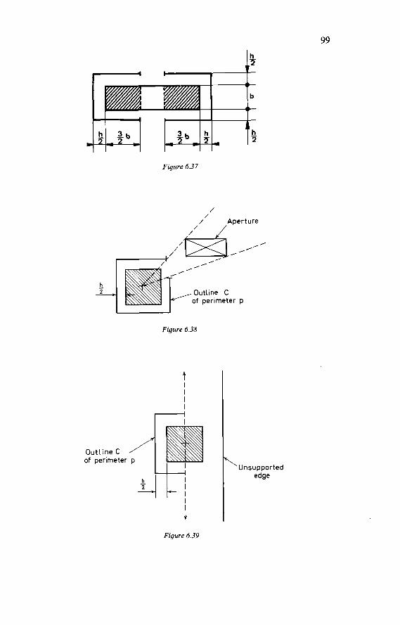
99
Figure 6.37
/ / Apert Ure / /
h 2 -
/
, / / -’ ,
Outline C of perimeter p
Figure 6.38
I
Outline C
I J.
Unsupported edge
Figure 6.39
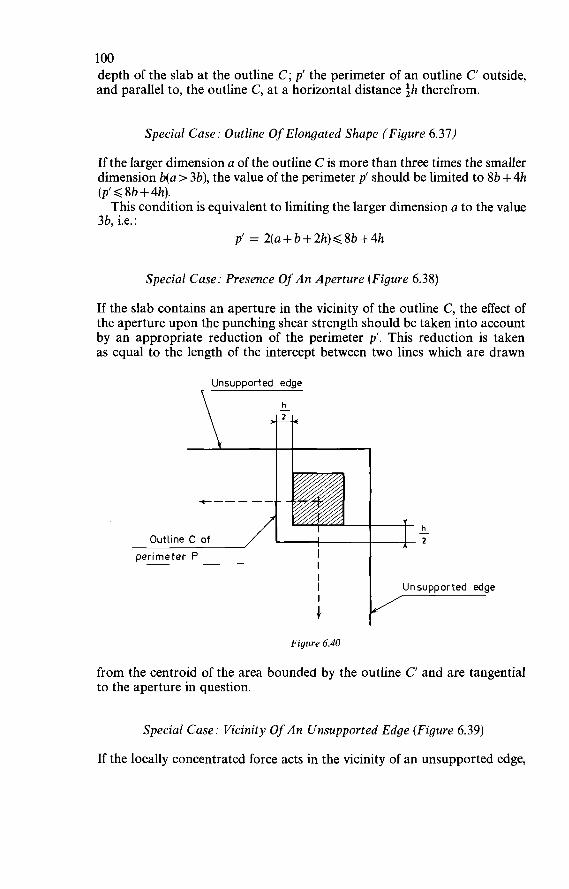
1 O0 depth of the slab at the outline C; p’ the perimeter of an outline C outside, and parallel to, the outline C, at a horizontal distance 3h therefrom.
Special Case: Outline Of Elongated Shape (Figure 6.37)
If the larger dimension a of the outline C is more than three times the smaller dimension b(a > 3b), the value of the perimeter p‘ should be limited to 8b + 4h (p’ < 8b + 4h). This condition is equivalent to limiting the larger dimension a to the value
3b, i.e. : p’ = 2(a+b+2h)d8b+4h
Special Case: Presence Of An Aperture (Figure 6.38)
If the slab contains an aperture in the vicinity of the outline C, the effect of the aperture upon the punching shear strength should be taken into account by an appropriate reduction of the perimeter p’. This reduction is taken as equal to the length of the intercept between two lines which are drawn
Unsupported edge
h
I l
Outline C of oerimeter P I
I
h 2 -
I Unsupported edge I G
Figure 6.40
from the centroid of the area bounded by the outline C and are tangential to the aperture in question.
Special Case: Vicinity Of A n Unsupported Edge (Figure 6.39)
If the locally concentrated force acts in the vicinity of an unsupported edge,
101 the latter should be treated as an aperture of infinite length in the direction parallel to this edge.
Special Case: Vicinity Of A n Unsupported Corner (Figure 6.40)
If the locally concentrated force acts in the vicinity of an unsupported corner, the latter should be treated as an aperture of infinite dimensions in the two directions parallel to this corner.
7
CONSTRUCTIONAL ARRANGEMENTS
7.1 AGREEMENT BETWEEN CONSTRUCTIONAL ARRANGEMENTS AND DESIGN ASSUMPTIONS
The constructional arrangements should be compatible with the basic data and with the fundamental design assumptions, more particularly with regard to : (a) the physical and mechanical behaviour of the materials; (b) the nature of the various connections between the component elements
of the structure (hinged joints, fixed connections, continuity con- ditions, etc.);
(c) the sequence of the various stages of construction (which should be anticipated and clearly indicated in the design calculations).
All relevant information concerning these data and assumptions should be made available to the contractor by the design engineer. If the contractor considers such information to be insufficient, he should request the designer for additional information.
7.2 GENERAL CONDITIONS RELATING TO THE REINFORCEMENT
7.2.1 SIMULTANEOUS USE OF DIFFERENT GRADES OR TYPES OF BARS
The use of different grades or different types of reinforcing bars in one and the same structural member should be avoided as far as possible. It can be allowed only if there is no real danger of confusing the bars of different grades or types. In practice the simultaneous use of two different grades or two types of
I02
103 reinforcing bars, one for the main reinforcement and the other for the stirrups and connector reinforcement of the same structural member, can be allowed. But in that case the designer should: (a) introduce each of these two grades or each of these two types of bars
with its proper reference strength and its proper basic strength into the design calculation;
(b) take account of the possible consequential effects of the respective properties of these various bars upon the verification of the condition of strain compatibility at each section.
The simultaneous use of two grades or two types of reinforcing bars is on no account permissible in all cases where there is even the slightest possible risk of confusion. This prohibition is more particularly applicable to the bars of which the main reinforcement of a structural member is composed. O n the other hand, the results of many tests and the experience of designers
extending over several decades have shown that it is allowable, in flexural members, to use simultaneously: deformed (high-bond) medium-tensile bars for the longitudinal reinforcement (tensile reinforcement, compressive reinforcement, short ‘cap’ bars) and plain bars for the transverse reinforce- ment (stirrups, binders, connectors) and also for bars used for fixing the reinforcement and for bars left projecting from the concrete (these usually have to undergo successive bending and forming operations and should, for this reason, have a higher capacity for to-and-fro bending than the longi- tudinal reinforcing bars). Although the geometrical conditions of strain compatibility cannot be strictly satisfied in all cases, this practice is justified by the fact that, for one thing, no major objections to it have ever been put forward and that, furthermore, abandonment of this practice would, in a great many simple cases, be disadvantageous from the viewpoint of economy.
7.2.2 PERMISSIBLE CURVATURE OF REINFORCING BARS
The radii of curvature of reinforcing bars should be determined with refer- ence to : (a) the risk of crushing of the concrete under the effect of local pressures
in the curve; (b) the ductility properties of the steel and its possibilities for bending
and shaping without any abnormal risks of immediate fracture or the formation of incipient fracture zones which are difficult to detect;
(c) the manner in which the bar-bending operations in the workshop and the steel-fixing operations on the construction site are carried out (Section 9.2.2).
Condition To Ensure That No Crushing Of The Concrete Will Occur
In preparing the working drawings for the various members of a structure the designer should, for all the curved portions of the reinforcing bars,

104 check that the condition to ensure that no crushing of the concrete will occur (Section 6.2.3) is satisfied. This check is necessary in actual practice only if all the bars of the same
hyer (or all the bars of the several layers) in the section under consideration have to be bent in the same place, e.g., at the corner of a portal frame. In the case of a single curved bar, too, it is generally unnecessary to check the con- dition for crushing of the concrete if the radius of curvature is less than 106.
Condition For Bar-Bending
The permissible nominal values for the radii of curvature r of the reinforcing bars (measured to the bar axis) and the corresponding minimum permissible diameters of the bar-bending formers are given in the Tables 7.1 and 7.2.
Table 7.1 Minimum radii of curvature
Mild steel Medium-tensile steel High-tensile steel
(u, > 5 O00 bars) (3 O00 bars < u, < 5 O00 bars) Minimum radii of
curvature (u, c 3 O00 bars)
Stirrups and binders 24 34 Anchorages 34 4.54 5.54 5.54 Bends 4-54 4.54 84 84 10.54 1054
Table 7.2 Minimum diameters of bar-bending formers
Mild steel Medium-tensile steel High-tensile steel (u, > 5000bars) (3 O00 bars < ue Q
5 O00 bars) (u e 3000bars) Minimum diameters of
forming mandrels @< 12mm 4 12mm 4 < 12mm 4 > 12mm 4 < 12mm 4 >12mm
Stirrups and binders 34 54 Anchorages 54 84 104 104 Bends 84 104 154 154 204 204
In Tables 7.1 and 7.2 the term ‘anchorages’ must be taken to include all devices utilising curvature to effect anchorage of the end of a bar into the concrete, while the term ‘bends’ refers to all changes of direction of a re- inforcing bar (for example, when a bar is bent up to assist in resisting shear force). The arrangement of the steel in large cantilevers such as are encounter- ed in the roofs of grand-stands or in certain structures of daring design calls for particular attention, since the bends in the bars of such structures are often located in the most severely stressed zones. According to Tables 7.1 and 7.2, reinforcing bars having an elastic limit of
more than 5 000 bars are not allowed to have anchorages based on curvature
105 and are not allowed to be used for binders and stirrups. Apart from being used in straight lengths, they are only allowed to be used as bent bars, and then only if they do not exceed 25 mm in diameter (4 < 25 mm).
7.2.3 CURTAILMENT OF REINFORCING B A R S
Devices Used At The Ends Of Reinforcing Bars
The devices used at the ends of reinforcing bars-hooks, in particular- should be so shaped that bending the bar involves no abnormal risk of fracture or initiation of fracture (Section 7.2.2) and that, when load is applied to the reinforcement, there is no risk of ‘unbalanced thrust’ nor of crushing of the concrete (Section 6.2.3). The positions of such end devices in relation to the adjacent faces of the
member should satisfy the same conditions.
Sudden Changes Of Section
The simultaneous curtailment of a considerable proportion of the bars at the same cross-section of the member should be avoided. T o fulfil this require- ment it is recommended to use a larger number of thinner bars (with the same total cross-sectional area), so that more satisfactory staggering of the ends of the bars can be achieved.
7.2.4 SPLICES I N REINFORCING B A R S
All splices in reinforcing bars should be envisaged in the design and shown on the working drawings and be executed in accordance with those drawings. There should be as few of these splices as possible. If they are essential, they should be located outside the zones where the severest stress con- ditions occur. T w o types of splicing are normally permitted:
(a) ‘lapped splices’, for bars not exceeding 32 mm in diameter; (b) ‘welded splices’, for bars of any diameter.
Lapped Splices
Laps In Tensile Reinforcement
Laps in tensile reinforcement should satisfy the requirements which specify the lap lengths, and those by which the corresponding fastening connectors can be designed or checked (Section 6.2.3). Besides, at any one particular cross-section the transmission of tensile
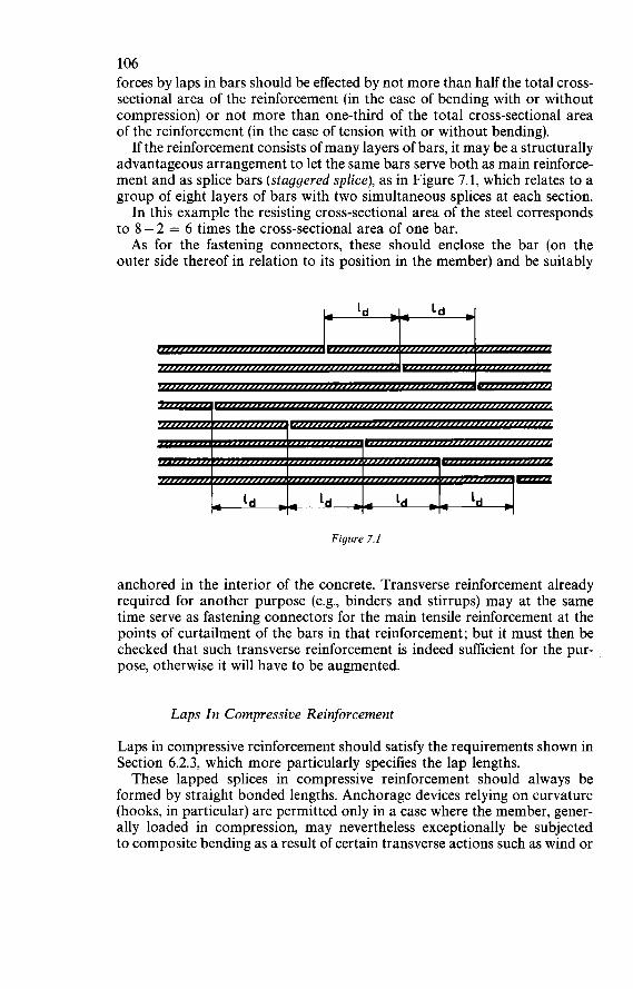
106 forces by laps in bars should be effected by not more than half the total cross- sectional area of the reinforcement (in the case of bending with or without compression) or not more than one-third of the total cross-sectional area of the reinforcement (in the case of tension with or without bending).
If the reinforcement consists of many layers of bars, it may be a structurally advantageous arrangement to let the same bars serve both as main reinforce- ment and as splice bars (staggered splice), as in Figure 7.1, which relates to a group of eight layers of bars with two simultaneous splices at each section. In this example the resisting cross-sectional area of the steel corresponds
to 8 - 2 = 6 times the cross-sectional area of one bar. As for the fastening connectors, these should enclose the bar (on the
outer side thereof in relation to its position in the member) and be suitably
Figure 7.1
anchored in the interior of the concrete. Transverse reinforcement already required for another purpose (e.g., binders and stirrups) may at the same time serve as fastening connectors for the main tensile reinforcement at the points of curtailment of the bars in that reinforcement; but it must then be checked that such transverse reinforcement is indeed sufficient for the pur- pose, otherwise it will have to be augmented.
Laps In Compressive Reinforcement
Laps in compressive reinforcement should satisfy the requirements shown in Section 6.2.3, which more particularly specifies the lap lengths. These lapped splices in compressive reinforcement should always be
formed by straight bonded lengths. Anchorage devices relying on curvature (hooks, in particular) are permitted only in a case where the member, gener- ally loaded in compression, may nevertheless exceptionally be subjected to composite bending as a result of certain transverse actions such as wind or
107 earthquake effects. In that case, however, the designer should take pre- cautions against ‘unbalanced thrust’ by the provision of fastening connectors of appropriate shape and cross-section (Section 6.2.3). In other words, the exception envisaged here concerns the case where
the compressive reinforcement may, in exceptional circumstances, be sub- jected to tension by the action of wind or earthquakes.
Welded Splices
Unless special justification for a departure from this stipulation is provided, splices formed by welding are permissible only for reinforcing bars with an elastic limit of not more than 5 O00 bars. In addition, the method of welding should not cause any impairment of the mechanical properties of the steel. This clause more particularly rules out the use of electric arc tack-welding
on the site to fix the transverse reinforcement (binders, stirrups, fastening connectors) to longitudinal reinforcing bars with an elastic limit exceeding 5 O00 bars. The tack welds are liable to initiate brittle fracture and are there- fore especially dangerous. As regards cold-worked reinforcing bars in particular, welded splices are
permissible only on condition that tests are performed to verify that the method of welding employed in no way impairs the mechanical properties of the bars (and especially the elastic limit and the ultimate strength). The manufacturers of such reinforcing steel often supply practical information with regard to this.
Nature Of Welded Splices
Provided that the reinforcing bars possess the properties that make them suitably weldable, welded splices may be formed in one of the following ways : (a) by means of butt welds produced by flash welding; (b) by means of butt welds, with formed edges, produced by electric arc
(c) by means of lap joints produced by electric arc welding with longitudi-
In general, welded butt joints (a) or (b) should be used, except in the case of bar splices at connections between precast reinforced concrete members and of splices inside formwork for which lap joints with longitudinal weld beads (c) are considered to be preferable. In this last-mentioned case the strength of the lap welds can be calculated
on the assumption that the shear strength of the welds (length x thickness of weld beads x 65 % of the tensile strength of the deposited weld metal as indicated by the supplier of the electrodes) should be at least 1.5 times the guaranteed ultimate strength of the bars to be welded and of any extra splice bars used. In addition, the length of the longitudinal weld beads should not exceed five times the diameter of the bar.
welding ;
nal weld beads.
108
exactly symmetrical and be as convenient as possible to execute. Finally, whichever type of welded splice is adopted the splice should be
Positioning Of Welded Splices
Welded splices should be confined to straight portions of reinforcing bars. Besides, they should be staggered in the longitudinal direction by a length equal to at least twenty times the bar diameter (204) in the case of plain round bars and at least ten times the bar diameter (104) in the case of deformed bars. Finally, in any one particular cross-section the transmission of tensile
forces by welded splices in bars should be effected by not more than half the total cross-sectional area of the reinforcement (in the case of bending with or without compression) or not more than one-third of the total cross- sectional area of the reinforcement (in the case of tension with or without bending).
Strength Of Welded Splices
Provided that the quality of the welds is strictly supervised, welded splices in tensile reinforcement and in compressive reinforcement can permissibly be utilised up to 100% of the strength of the bars they connect. This rule is allowed to be applied only if the welding operations are carried
out by a properly qualified welder and are under constant and strict supervision.
7.2.5 SPACING OF REINFORCING BARS
The spacing of reinforcing bars -i.e., the distances between adjacent bars within the section - should be sufficient to enable the concreting to be done in an entirely satisfactory manner. In particular, the bars should be so spaced that the freshly mixed concrete can be properly placed without risk of segregation and that the concrete surrounding the reinforcement can be efficiently vibrated. The values stated below correspond to normal ‘in situ’ concreting. Subject
to special justification, they may be reduced in the case of factory-made prec;ast members or in the case of temporary structures.
Spacing Of Bars In The Same Vertical Line
The clear vertical distance between two bars in the same vertical line in the cross-section of a member should be at least equal to the largest of the following values : (a) 1 cm (b) three-quarters of the diameter (0.754) of the thicker bar .
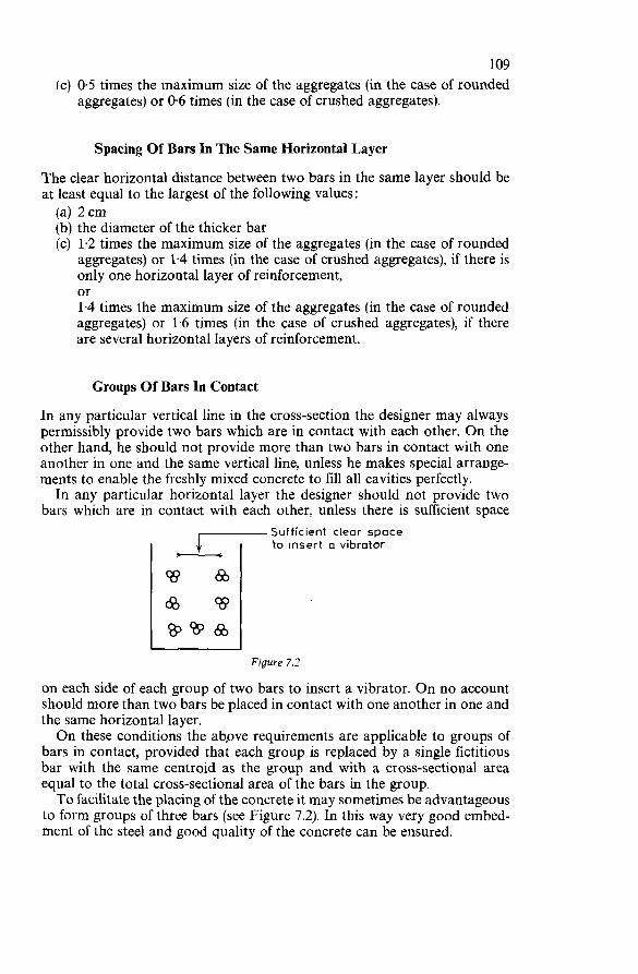
1 o9 (c) 0.5 times the maximum size of the aggregates (in the case of rounded
aggregates) or 0.6 times (in the case of crushed aggregates).
Spacing Of Bars In The Same Horizontal Layer
The clear horizontal distance between two bars in the same layer should be at least equal to the largest of the following values : (a) 2 cm (b) the diameter of the thicker bar (c) 1.2 times the maximum size of the aggregates (in the case of rounded
aggregates) or 1.4 times (in the case of crushed aggregates), if there is only one horizontal layer of reinforcement, or 1.4 times the maximum size of the aggregates (in the case of rounded aggregates) or 1.6 times (in the case of crushed aggregates), if there are several horizontal layers of reinforcement.
Groups Of Bars In Contact
In any particular vertical line in the cross-section the designer may always permissibly provide two bars which are in contact with each other. On the other hand, he should not provide more than two bars in contact with one another in one and the same vertical line, unless he makes special arrange- ments to enable the freshly mixed concrete to fill all cavities perfectly. In any particular horizontal layer the designer should not provide two
bars which are in contact with each other, unless there is sufficient space Sufficient clear space to insert a vibrator
Figure 7.2
on each side of each group of two bars to insert a vibrator. O n no account should more than two bars be placed in contact with one another in one and the same horizontal layer. O n these conditions the ab,ove requirements are applicable to groups of
bars in contact, provided that each group is replaced by a single fictitious bar with the same centroid as the group and with a cross-sectional area equal to the total cross-sectional area of the bars in the group. To facilitate the placing of the concrete it may sometimes be advantageous
to form groups of three bars (see Figure 7.2). In this way very good embed- ment of the steel and good quality of the concrete can be ensured.
110 Laboratory tests have shown that when ribbed deformed bars (high-
bond bars with ribbed surface profile) are used, the space inside such a group of three bars is filled with mortar from the concrete. Also, to facilitate the placing and vibration of the concrete, it is sometimes
helpful to install binders or stirrups in twinned pairs.
Bar Spacings At Intersections O f Beams
The designer should, as far as possible, avoid excessive concentration of reinforcing bars in certain zones of the structure. But such concentration is hard to avoid at intersections of beams if the bars are placed at levels that are close together and especially if, in such places, suspender bars are essential for transmitting the forces. Such concentration of reinforcement may interfere with the proper placing of the concrete and impair the quality thereof. To facilitate the placing of the concrete and improve its quality in zones
where there is considerable concentration of bars, the designer may, if need be, specify a special concrete, with a smaller maximum size of aggregate, for such zones. In that case the maximum size of the aggregate particles should not exceed the ratio of the volume of the mould to the total surface area of its walls (calculated as the sum of the areas of the concrete faces and of the surfaces of the reinforcing bars).
7.2.6 CONCRETE COVER TO REINFORCEMENT
The concrete cover to the reinforcement - i.e., the distance from the bars to the walls of the formwork or to the free surface of the concrete - should be sufficient to enable concreting to be done in an entirely satisfactory manner, so that, in particular, all risk of segregation is obviated and the concrete can be compacted to the density that is essential to providing suitable protection of the reinforcement against corrosive agents.
Arrangements Common To All Reinforcement Bars
The clear amount of cover between any point of the external generating lines of any bar (longitudinal reinforcement, transverse reinforcement, connector reinforcement or steel-fixing bars) and the nearest face of the concrete should be at least equal to: (a) 1 cm, if the concrete faces are protected not only from all chemical
attack, but also from all atmospheric influences and condensation phenomena.
(b) 2cm, if the concrete faces, even though they are not exposed to any particular chemical attack, are nevertheless exposed to atmospheric influences (external members) or to condensation phenomena (kitchens,
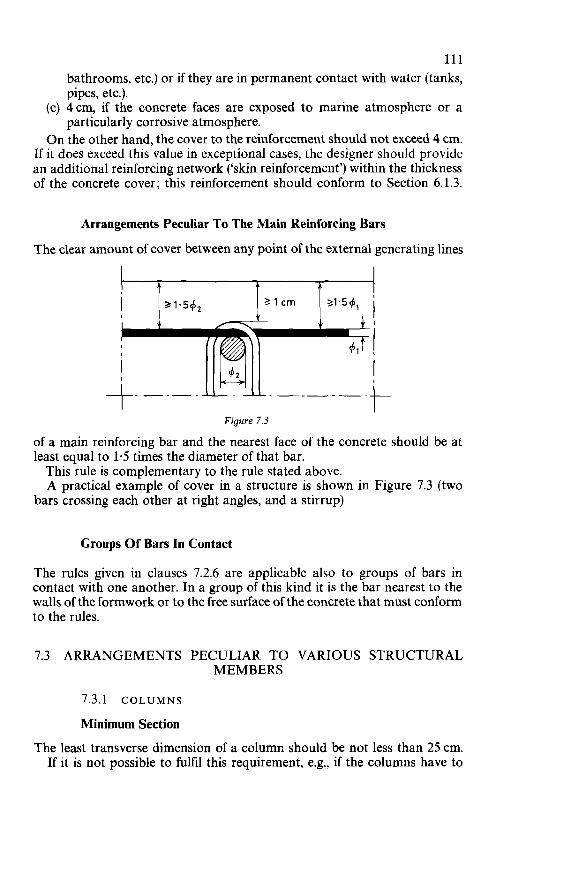
111 bathrooms, etc.) or if they are in permanent contact with water (tanks, pipes, etc.).
(c) 4cm, if the concrete faces are exposed to marine atmosphere or a particularly corrosive atmosphere.
O n the other hand, the cover to the reinforcement should not exceed 4 cm. If it does exceed this value in exceptional cases, the designer should provide an additional reinforcing network (‘skin reinforcement’) within the thickness of the concrete cover; this reinforcement should conform to Section 6.1.3.
Arrangements Peculiar To The Main Reinforcing Bars
The clear amount of cover between any point of the external generating lines
t t
Figure 7.3
of a main reinforcing bar and the nearest face of the concrete should be at least equal to 1.5 times the diameter of that bar. This rule is complementary to the rule stated above. A practical example of cover in a structure is shown in Figure 7.3 (two
bars crossing each other at right angles, and a stirrup)
Groups Of Bars In Contact
The rules given in clauses 7.2.6 are applicable also to groups of bars in contact with one another. In a group of this kind it is the bar nearest to the walls of the formwork or to the free surface of the concrete that must conform to the rules.
7.3 ARRANGEMENTS PECULIAR TO VARIOUS STRUCTURAL MEMBERS
7.3.1 COLUMNS
Minimum Section
The least transverse dimension of a column should be not less than 25 cm. If it is not possible to fulfil this requirement, e.g., if the columns have to
112 be accommodated within the thickness of walls or partitions, the least transverse dimension may be reduced below 25cm on the following conditions : (a) the reference strength of the concrete (Section 3.2.1) should be at least
(b) the geometrical percentage of longitudinal reinforcement should be at 200 bars;
least one per cent (1 %).
Longitudinal Reinforcement
Minimum Elastic Limit
The longitudinal reinforcing bars should have a reference elastic limit o, of at least 4 o00 bars (o, 2 4 O00 bars); they may, at the designer’s option, be plain round bars or deformed bars (high-bond bars). If it is not possible to fulfil this requirement, i.e., if the longitudinal rein-
forcing bars have a reference elastic limit oe of less than 4 O00 bars (o, < 4 O00 bars), the basic compressive strength must be reduced in the ratio of o,/4 000, i.e., by multiplying it by a reduction coefficient o,/4 000.
Minimum Percentage
The minimum geometrical percentage of longitudinal reinforcement, referred to the total cross-sectional area of the column should be:
(a) for a corner column:
.ß. l+- 3 42- 1 O00 ( 4y)
(b) for an edge column: ab 2 - 2.5 . ß . (1 +?)
1 O00
(c) for an internal column:
where oe denotes the reference elastic limit of the steel (above 4000 bars, apart from exceptional cases, see above) and ß denotes the ratio between the external direct force (as determined from the characteristic loadings) and the resistance to direct force that the concrete section can develop (equal to 0.750b. B’). Introduction of the coefficient fl corresponds to the case where the column
has an excessive concrete section. Applying this coefficient is equivalent to
113 referring the minimum percentage of reinforcement to the concrete section that is strictly necessary for the equilibrium of the external direct force.
Examples Of Application
It will be assumed that the steel has a reference elastic limit of 4200 bars and that the concrete section of the columns is 10% ‘excessive’ (as envisaged in the preceding paragraph, p = (1/1.15). The basic compressive strength of the steel should be taken as:
- = 2 335 bars 4 200 1.80
with a minimum geometrical percentage of: 0.003 O. (1/1.15). [i +(4 000/4 200)] = 0.534% for the corner columns 0.002 5. (1/1.15). [i +(4 000/4 200)] = 0446% for the edge columns 0.002 O. (1/1.15). [i +(4 000/4 200)] = 0.357 % for the internal columns
If, on the other hand, the steel is assumed to have a reference elastic limit of 3 600 bars, the basic compressive strength of the steel should be taken as:
--=-- 600 6oo 240 - 1 800 bars (instead of 2 O00 bars) 1.80 ‘4000 1.80 with a minimum geometrical percentage of: 0~0030(1/1~15) [i +(4000/3240)] = 0.583 % for the corner columns 0.0025 (1p.15) [ 1 + (4000/3240)] = 0.486 % for the edge columns 0.0020(1/1.15) [i +(4000/3240)] = 0.389 % for the internal columns
If, for compelling structural reasons, the least transverse dimension of the columns will have to be made less than 25 cm, these minimum geometrical percentages should be increased to 1 % for all the columns.
Constructional Arrangements
The longitudinal reinforcing bars should be so distributed within the section in the vicinity of the sides of the column as to give the latter the best possible flexural resistance in the most unfavourable directions. In particular, in a column with an elongated rectangular section, the distance between two adjacent longitudinal bars should not exceed the width of the section (i.e., the dimension of the shorter side).
Transverse Reinforcement
Minimum Diameter
The diameter of the transverse reinforcing bars should be at least equal to 5 mm and not less than one-quarter of the diameter of the thickest longi- tudinal reinforcing bar.
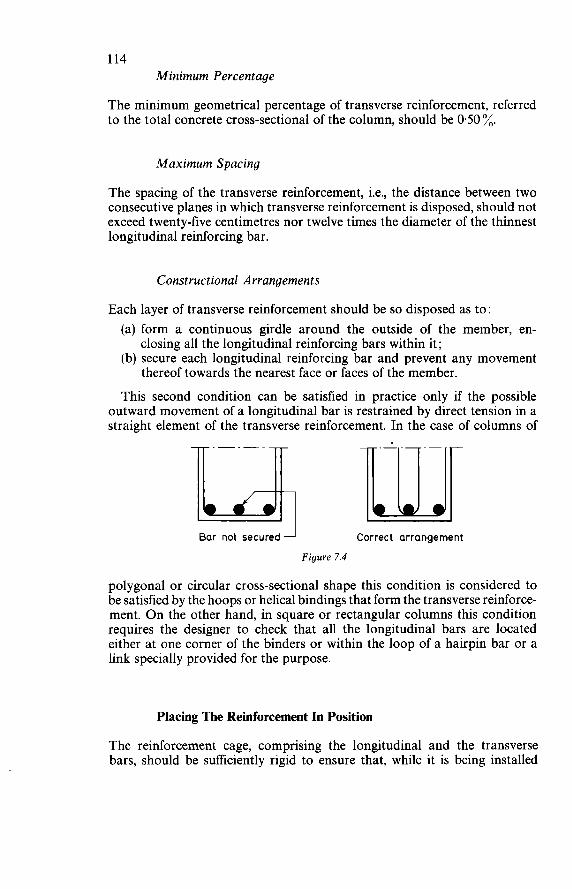
114 Minimum Percentage
The minimum geometrical percentage of transverse reinforcement, referred to the total concrete cross-sectional of the column, should be 0.50 %.
M a x i m u m Spacing
The spacing of the transverse reinforcement, i.e., the distance between two consecutive planes in which transverse reinforcement is disposed, should not exceed twenty-five centimetres nor twelve times the diameter of the thinnest longitudinal reinforcing bar.
Constructional Arrangements
Each layer of transverse reinforcement should be so disposed as to : (a) form a continuous girdle around the outside of the member, en-
(b) secure each longitudinal reinforcing bar and prevent any movement
This second condition can be satisfied in practice only if the possible outward movement of a longitudinal bar is restrained by direct tension in a straight element of the transverse reinforcement. In the case of columns of
closing all the longitudinal reinforcing bars within it;
thereof towards the nearest face or faces of the member.
Bar not securedl Correct arrangement
Figure 7.4
polygonal or circular cross-sectional shape this condition is considered to be satisfied by the hoops or helical bindings that form the transverse reinforce- ment. O n the other hand, in square or rectangular columns this condition requires the designer to check that all the longitudinal bars are located either at one corner of the binders or within the loop of a hairpin bar or a link specially provided for the purpose.
Placing The Reinforcement In Position
The reinforcement cage, comprising the longitudinal and the transverse bars, should be sufficiently rigid to ensure that, while it is being installed
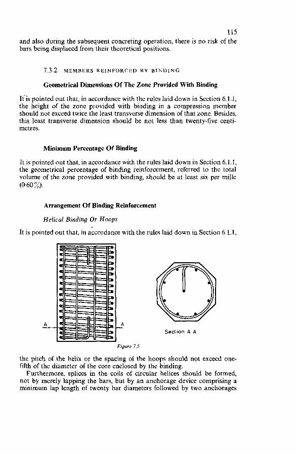
115 and also during the subsequent concreting operation, there is no risk of the bars being displaced from their theoretical positions.
7.3.2 MEMBERS REINFORCED BY BINDING
Geometrical Dimensions Of The Zone Provided With Binding
Itis pointed out that, in accordance with the rules laid down in Section 6.1.1, the height of the zone provided with binding in a compression member should not exceed twice the least transverse dimension of that zone. Besides, this least transverse dimension should be not less than twenty-five centi- metres.
Minimum Percentage O f Binding
It is pointed out that, in accordance with the rules laid down in Section 6.1.1, the geometrical percentage of binding reinforcement, referred to the total volume of the zone provided with binding, should be at least six per mille (0.60 x).
Arrangement Of Binding Reinforcement
Helical Binding Or Hoops
It is pointed out that, in accordance with the rules laid down in Section 6.1.1,
A -. A - rigure 7.5
Section A A
the pitch of the helix or the spacing of the hoops should not exceed one- fifth of the diameter of the core enclosed by the binding. Furthermore, splices in the coils of circular helices should be formed,
not by merely lapping the bars, but by an anchorage device comprising a minimum lap length of twenty bar diameters followed by two anchorages
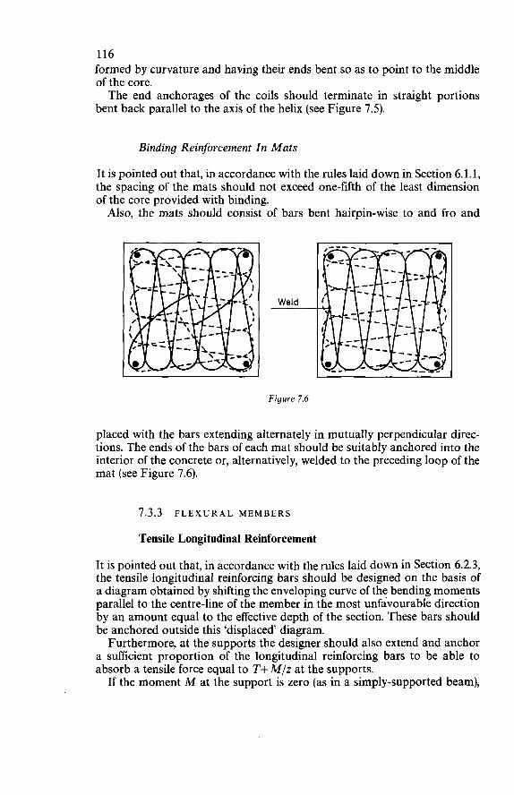
116 formed by curvature and having their ends bent so as to point to the middle of the core. The end anchorages of the coils should terminate in straight portions
bent back parallel to the axis of the helix (see Figure 7.5).
Binding Reinforcement In Mats
It is pointed out that, in accordance with the rules laid down in Section 6.1.1, the spacing of the mats should not exceed one-fifth of the least dimension of the core provided with binding. Also, the mats should consist of bars bent hairpin-wise to and fro and
Figure 7.6
placed with the bars extending alternately in mutually perpendicular direc- tions. The ends of the bars of each mat should be suitably anchored into the interior of the concrete or, alternatively, welded to the preceding loop of the mat (see Figure 7.6).
7.3.3 FL E X U R A L MEMBERS
Tensile Longitudinal Reinforcement
It is pointed out that, in accordance with the rules laid down in Section 6.2.3, the tensile longitudinal reinforcing bars should be designed on the basis of a diagram obtained by shifting the enveloping curve of the bending moments parallel to the centre-line of the member in the most unfavourable direction by an amount equal to the effective depth of the section. These bars should be anchored outside this ‘displaced diagram. Furthermore, at the supports the designer should also extend and anchor
a sufficient proportion of the longitudinal reinforcing bars to be able to absorb a tensile force equal to T+ M/z at the supports.
If the moment M at the support is zero (as in a simply-supported beam),
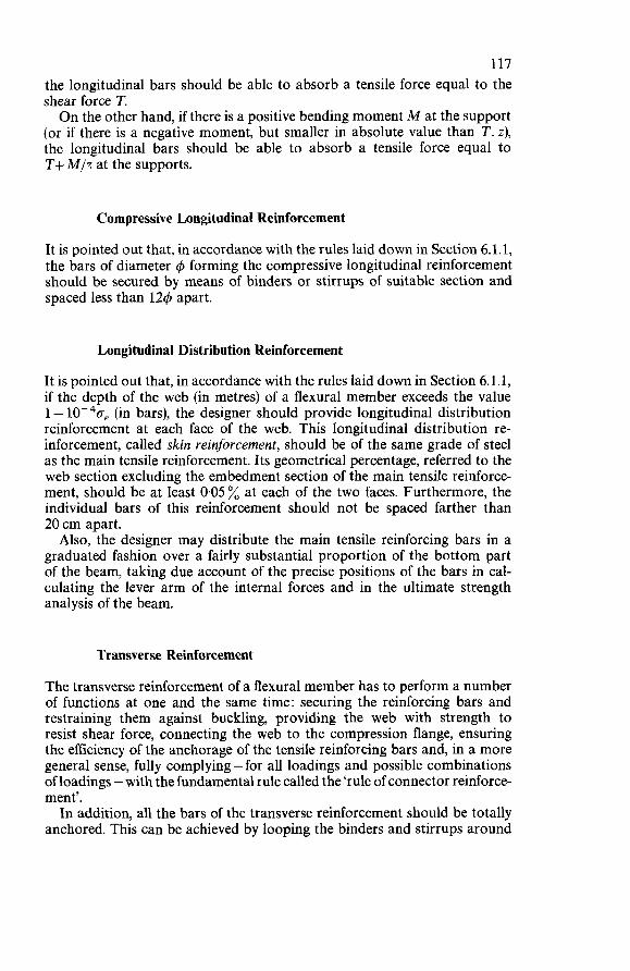
117 the longitudinal bars should be able to absorb a tensile force equal to the shear force T. O n the other hand, if there is a positive bending moment M at the support
(or if there is a negative moment, but smaller in absolute value than T. z), the longitudinal bars should be able to absorb a tensile force equal to T+ M/T at the supports.
Compressive Longitudinal Reinforcement
It is pointed out that, in accordance with the rules laid down in Section 6.1.1, the bars of diameter 4 forming the compressive longitudinal reinforcement should be secured by means of binders or stirrups of suitable section and spaced less than 124 apart.
Longitudinal Distribution Reinforcement
It is pointed out that, in accordance with the rules laid down in Section 6.1.1, if the depth of the web (in metres) of a flexural member exceeds the value 1 - 10-40, (in bars), the designer should provide longitudinal distribution reinforcement at each face of the web. This longitudinal distribution re- inforcement, called skin reinjorcement, should be of the same grade of steel as the main tensile reinforcement. Its geometrical percentage, referred to the web section excluding the embedment section of the main tensile reinforce- ment, should be at least 0.05% at each of the two faces. Furthermore, the individual bars of this reinforcement should not be spaced farther than 20 cm apart. Also, the designer may distribute the main tensile reinforcing bars in a
graduated fashion over a fairly substantial proportion of the bottom part of the beam, taking due account of the precise positions of the bars in cal- culating the lever arm of the internal forces and in the ultimate strength analysis of the beam.
Transverse Reinforcement
The transverse reinforcement of a flexural member has to perform a number of functions at one and the same time: securing the reinforcing bars and restraining them against buckling, providing the web with strength to resist shear force, connecting the web to the compression flange, ensuring the efficiency of the anchorage of the tensile reinforcing bars and, in a more general sense, fully complying - for all loadings and possible combinations of loadings - with the fundamental rule called the ‘rule of connector reinforce- ment’. In addition, all the bars of the transverse reinforcement should be totally
anchored. This can be achieved by looping the binders and stirrups around
118 the main reinforcing bars, provided that the angle that these binders and stirrups make with the longitudinal bars is not less than 65". In other words, the anchorage of binders and stirrups inclined at an angle
of more than 65" in relation to the longitudinal axis of the member should be specially investigated and designed accordingly. Finally, the spacing of the successive layers of transverse reinforcement
should not exceed twenty centimetres (for deep beams) nor exceed eighty- five hundredths of the effective depth (for beams of low and of medium depth). In the frequently encountered case of a rectangular rib joined to a top
slab and containing transverse reinforcement which is perpendicular to the
centre-line of the rib and anchored by looping or hooking round the longi- tudinal bars, it is not sufficient merely to provide stirrups in separate rows around each longitudinal bar. The bottom (tensile) face of the rib should also be reinforced transversely, either by means of general binders, or by means of short links, or by other means (see Figure 7.7).
Changes In The Geometrical Shapes Of Sections
In the design calculations for a flexural member it is often found necessary to vary the depth or the width of the cross-sections. The designer may make the depth or the width of the section vary continuously all along the member or he may alternatively, and more conveniently, increase the depth locally in the form of haunches at the supports. The slope of such haunches in rela- tion to the longitudinal axis of the member should not exceed one-third.
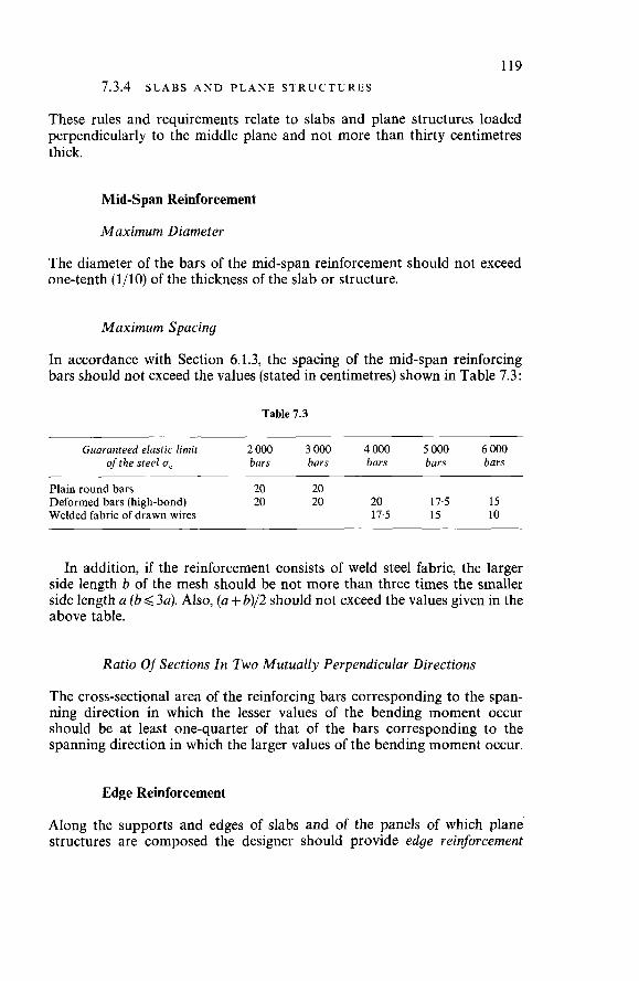
119 7.3.4 SLABS AND PLANE STRUCTURES
These rules and requirements relate to slabs and plane structures loaded perpendicularly to the middle plane and not more than thirty centimetres thick.
Mid-Span Reinforcement
M a x i m u m Diameter
The diameter of the bars of the mid-span reinforcement should not exceed one-tenth (l/lO) of the thickness of the slab or structure.
M a x i m u m Spacing
In accordance with Section 6.1.3, the spacing of the mid-span reinforcing bars should not exceed the values (stated in centimetres) shown in Table 7.3:
Table 7.3
Guaranteed elastic limit 2000 3000 4000 5000 6000 of the steel o, bars bars bars bars bars
Plain round bars 20 20 Deformed bars (high-bond) 20 20 20 17.5 15 Welded fabric of drawn wires 17.5 15 10
In addition, if the reinforcement consists of weld steel fabric, the larger side length b of the mesh should be not more than three times the smaller side length a (b< 3a). Also, (a + b)/2 should not exceed the values given in the above table.
Ratio Of Sections In Two Mutually Perpendicular Directions
The cross-sectional area of the reinforcing bars corresponding to the span- ning direction in which the lesser values of the bending moment occur should be at least one-quarter of that of the bars corresponding to the spanning direction in which the larger values of the bending moment occur.
Edge Reinforcement
Along the supports and edges of slabs and of the panels of which plane structures are composed the designer should provide edge reinforcement
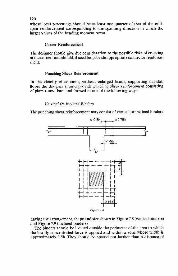
120 whose local percentage should be at least one-quarter of that of the mid- span reinforcement corresponding to the spanning direction in which the larger values of the bending moment occur.
Corner Reinforcement
The designer should give due consideration to the possible risks of cracking at the corners and should, if need be, provide appropriate connector reinforce- ment.
Punching Shear Reinforcement
In the vicinity of columns, without enlarged heads, supporting flat-slab floors the designer should provide punching shear reinforcement consisting of plain round bars and formed in one of the following ways:
Vertical Or Inclined Binders
The punching shear reinforcement may consist of vertical or inclined binders
s 0.5h- I ~0115h
Figure 7.8
having the arrangement, shape and size shown in Figure 7.8 (vertical binders) and Figure 7.9 (inclined binders). The binders should be located outside the perimeter of the area to which
the locally concentrated force is applied and within a zone whose width is approximately 1.5h. They should be spaced not farther than a distance of
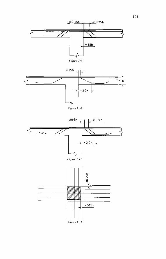
121
~0.5h
\
+
A
Figure 7.9
4 T
I h
-?Oh c
Figure 7.12
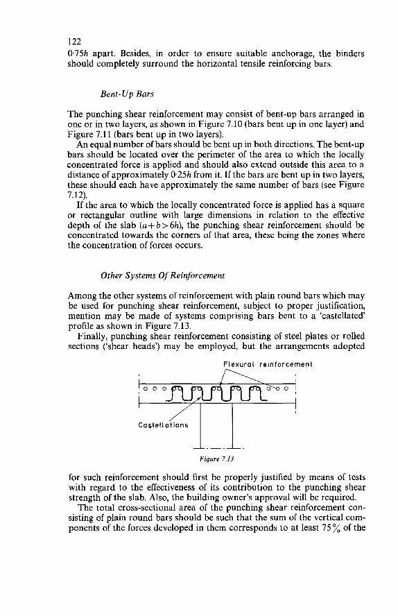
122 0.75h apart. Besides, in order to ensure suitable anchorage, the binders should completely surround the horizontal tensile reinforcing bars.
Bent-Up Bars
The punching shear reinforcement may consist of bent-up bars arranged in one or in two layers, as shown in Figure 7.10 (bars bent up in one layer) and Figure 7.11 (bars bent up in two layers). An equal number of bars should be bent up in both directions. The bent-up
bars should be located over the perimeter of the area to which the locally concentrated force is applied and should also extend outside this area to a distance of approximately 0.25h from it. If the bars are bent up in two layers, these should each have approximately the same number of bars (see Figure 7.12). If the area to which the locally concentrated force is applied has a square
or rectangular outline with large dimensions in relation to the effective depth of the slab (a + b > 6h), the punching shear reinforcement should be concentrated towards the corners of that area, these being the zones where the concentration of forces occurs.
Other Systems Of Reinforcement
Among the other systems of reinforcement with plain round bars which may be used for punching shear reinforcement, subject to proper justification, mention may be made of systems comprising bars bent to a ‘castellated’ profile as shown in Figure 7.13. Finally, punching shear reinforcement consisting of steel plates or rolled
sections (‘shear heads’) may be employed, but the arrangements adopted
Flexural reinforcement
Ca st e li át io n s
Figure 7.13
for such reinforcement should first be properly justified by means of tests with regard to the effectiveness of its contribution to the punching shear strength of the slab. Also, the building owner’s approval will be required. The total cross-sectional area of the punching shear reinforcement con-
sisting of plain round bars should be such that the sum of the vertical com- ponents of the forces developed in them corresponds to at least 75 % of the
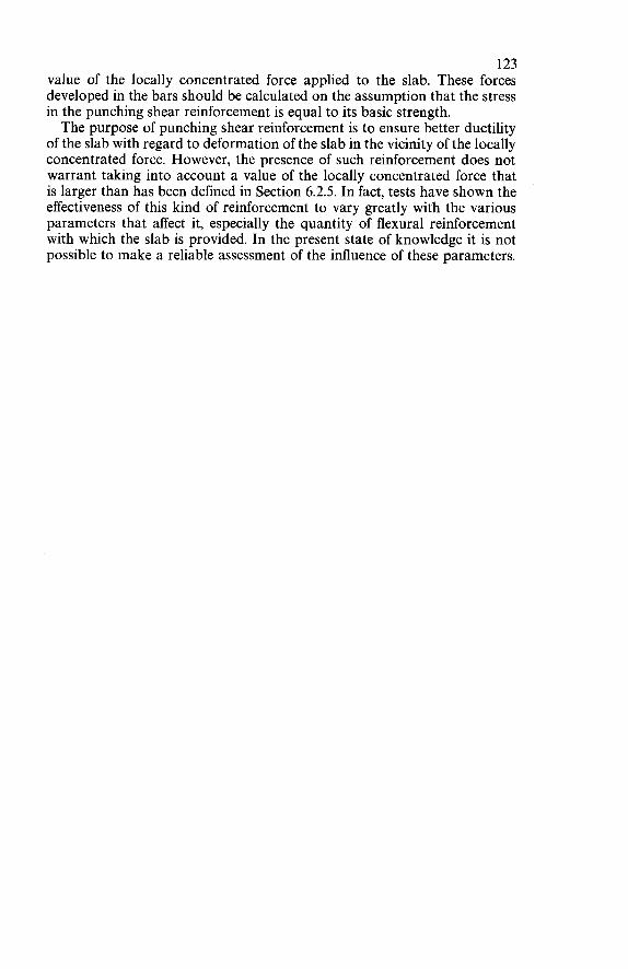
123 value of the locally concentrated force applied to the slab. These forces developed in the bars should be calculated on the assumption that the stress in the punching shear reinforcement is equal to its basic strength. The purpose of punching shear reinforcement is to ensure better ductility
of the slab with regard to deformation of the slab in the vicinity of the locally concentrated force. However, the presence of such reinforcement does not warrant taking into account a value of the locally concentrated force that is larger than has been defined in Section 6.2.5. In fact, tests have shown the effectiveness of this kind of reinforcement to vary greatly with the various parameters that affect it, especially the quantity of flexural reinforcement with which the slab is provided. In the present state of knowledge it is not possible to make a reliable assessment of the influence of these parameters.
8
PREPARATION OF DESIGNS
8.1 CALCULATIONS
8.1.1 BASIC DATA FOR DESIGN CALCULATIONS
Before preparing any detailed calculations the designer should obtain the building owner’s (or his representative’s) agreement on the basic data to be adopted for these calculations. These data must be conformed to by those entrusted with the construction
and by the users of the structure, more particularly with regard to: (a) the bearing pressure of the foundations on the soil; (b) the nominal working loads, i.e. fixed or mobile superimposed loads
(c) the reference value of the compressive (and, where relevant, the tensile)
(d) the reference value of the elastic limit of the steel and also the other
(live loads);
strength of the concrete;
mechanical properties specified in the conditions of approval.
8.1.2 ARITHMETICAL A C C U R A C Y OF THE CALCULATIONS
Assuming the basic data for the design calculations to have been accepted by the building owner or his representative, the arithmetical check of these calculations is to be considered satisfactory if the deviations found in them do not exceed 3 % (plus or minus). If this requirement is fulfilled, the building owner will not be entitled to use such deviations as grounds for demanding a modification of the design; in the contrary case, however, he will be entitled to demand such modification.
8.1.3 SUBMISSION OF CALCULATIONS
If the design is prepared by or on behalf of the contractor, the contract documents should state whether the contractor is required to supply the
I24
125 building owner or his representative with a complete set of typewritten design calculations for all the component members of the structure. Other- wise the contractor need merely, if so required, make available to the building owner or his representative the handwritten draft calculations.
8.2 DRAWINGS
8.2.1 PRELIMINARY DESIGN DRAWINGS
Preliminary design drawings accompanying the contractor’s tender should be drawn to a scale of 1 : 50; they may be of a schematic character and need not show reinforcement details. However, on putting in his tender the contractor is deemed thereby to undertake the obligation, if he is awarded the contract, subsequently to conform to all the requirements of the code of practice as embodied in this Manual.
8.2.2 WORKING DRAWINGS
The working drawings should show, with the exactness and precision con- sidered necessary by the building owner or his representative, all the geo- metrical shapes of the component members of the structure and all the reinforcement details.
Arrangements Common To All Working Drawings
All working drawings should give ;he following information in a special boxed-in space on the title page of the folded document: (a) Name of the structure; (b) Name of the building owner; (c) Name of the building owner’s representative (architect or consulting
(d) Name of the contractor (if the design is prepared by or on behalf of the
(e) Name of the reinforced concrete designer; (f) Names of the draughtsmen; (g) Title of the drawing; (h) Number of the drawing; (i) Date of drawing; ci) Scale; (k) Amendments; (i) Name and signature of the person responsible for the reinforced
The following information should also be very clearly shown on all work-
(a) the most-unfavourable loads transmitted to each of the foundations;
engineer) ;
contractor);
concrete design.
ing drawings:
126 (b) the nominal working loads (fixed superimposed loads. and live loads)
and the weight of top and bottom surfacings and finishes; (c) the guaranteed minimum compressive strengths (and, where relevant,
tensile strengths) of the concrete; (d) the guaranteed mechanical properties of the steel, including more
particularly : the guaranteed elastic limit and, for all bars that have to be bent, the permissible radius of curvature and the corresponding minimum diameter of the bar-bending former.
Finally, the working drawings should show all construction joints, all fixing holes and sockets to be subsequently concreted or grouted up, and all openings, and should, in the case of a floor, indicate whether it is pro- vided with underfloor heating.
Formwork Drawings The formwork drawings should show the various planes, sections and
elevations of the actual structural surfaces, not including any finishes or coatings. They should, in particular, show all the dimensions necessary for the correct setting-out and complete execution of all the components of the structure. As regards heights and thicknesses, the formwork drawings should show the total heights (or depths) and thicknesses of the concrete, not including the various surfacings and finishes.
Reinforcement Drawings The reinforcement drawings should show all the details necessary for the correct execution and accurate fixing of the reinforcement. They should, in particular, clearly indicate the guaranteed minimum elastic limit of the steel, the length of each bar, the geometrical features of curves and bends, the diameter of the bar-bending former, the bar spacings and the distances between the bars and the concrete faces, more particularly at intersections of beams and at the junctions of slabs and columns. In addition, for those parts of the structure where the reinforcement is
particularly dense the drawings should comprise large-scale details clearly showing the interlacing of the bars (and, if need be, the essential arrange- ments to enable the concrete to be properly placed). Finally, if the simultaneous use of several different grades or types of
reinforcing bars is to be allowed, the reinforcement drawings should clearly show the grade or type of steel of the various bars. If symbols are employed for distinguishing these various steel grades or types, the meanings of such symbols should be clearly explained in a very prominent boxed-in space on the drawing.
8.3 CONDITIONS OF EXECUTION
Of the conditions of execution which have received the building owner’s approval, the designs should define and justify those which are liable to
127 affect the strength or the stability of the structure and which, in more general terms, may affect its behaviour during the period of construction or during its subsequent service life. In particular, the designs should define and justify : (a) the conditions of construction and stability of the formwork and its
ability to withstand the pressure of the freshly placed concrete and such consequential effects as this may have on the concreting procedure;
(b) the treatment to be applied to the exposed concrete surfaces and the possible consequential effects thereof upon the design and treatment of the formwork surfaces;
(c) the devices for fixing the reinforcing bars in relation to the formwork; (d) the procedure for construction in successive portions, and the justi-
fication of the strength and stability of the structure in each of the successive stages of construction;
(e) the construction joints and their possible effects upon the strength and stability of the structure;
(f) the conditions of removing the propping and formwork; (g) the temporary shrinkage joints;
etc.
9
EXECUTION OF STRUCTURES
9.1 REQUIREMENTS PERTAINING TO FORMWORK
9.1.1 CLASSIFICATION A N D CONSTRUCTION OF F O R M W O R K
Classification Of Formwork
Four categories of formwork (shuttering) or faces of moulds are to be dis- tinguished, classified as follows in ascending order of quality:
(a) ordinary formwork ; (b) carefully finished formwork; (c) fine-faced formwork; (d) special formwork.
For each concrete surface of a structure the category of formwork to be applied should be specified in the contract documents.
Ordinary Formwork
If ordinary formwork consists of sawn boards merely assembled side by side, these should be properly joined edge to edge. If ordinary formwork consists of fibreboard or plywood panels merely
assembled side by side, these should be properly joined edge to edge.
Carefully Finished Formwork
If carefully finished formwork consists of sawn boards planed (wrought) on all four surfaces and merely assembled side by side, the boards should be properly joined edge to edge.
128
129 If carefully finished formwork consists of fibreboard or plywood panels,
these should present a surface equivalent to that of planed timber. The tightness (against leakage) of the joints should be ensured by appropriate means. Adhesive strips should preferably consist of cellular material. They should
be installed within the thickness of the joint, because tapes that are simply stuck to the surface tend to become detached under the combined action of the formwork release agent and the vibration of the concrete. Carefully finished formwork may be made of steel. The steel plate surfaces
in contact with the concrete must be quite free from projections and from buckling. The tightness (against leakage) of the joints should be ensured by appropriate means. The joints of steel formwork may, for example, be sealed by means of
adhesive tapes applied flat to the internal formwork surfaces, or by means of resilient foamed material placed in the joints, or by means of a mastic compound.
Fine-Faced Formwork
If fine-faced formwork consists of boards planed on all four surfaces, the arrangement of the boards and the method of forming the joints should, for any one and the same concrete face, be specially designed from the aesthetic point of view. These boards may simply be assembled side by side or they may be fitted together with tongue-and-groove joints; in both cases the faces in contact with the concrete should, if necessary, be smoothed by planing after assembly. Fine-faced formwork consisting of fibreboard or plywood panels should
conform to the requirements laid down for carefully finished formwork of similar construction. But, in addition, the arrangement of the joints should be designed from the aesthetic point of view. These joints should be caulked and smoothed with a mastic compound. Adhesive tape must not be used. If fine-faced formwork is made of steel, the steel plate surfaces in contact
with the concrete must be quite free from projections and from buckling. The joints should be sealed by filling them with packings of resilient foamed material or any other equivalent method. The means employed for sealing the joints must not protrude from the
internal surface of the formwork. In addition, the joints should be caulked and smoothed with a mastic compound. Adhesive tape must not be used. The pattern of the joints should be designed from the aesthetic point
of view.
Special Formwork
Where necessary, the requirements applicable to special formwork should be specified in the contract documents.
130
for making precast units. Special formwork may be necessary for producing particular shapes and
Joints In Formwork
If adhesive tapes are used for sealing the joints in formwork, they should adhere so firmly that there is no risk of their becoming detached during concreting, even if formwork release agents are employed. Detachment of adhesive tapes is very objectionable for the aesthetic
appearance of the concrete surfaces. It is possible to obtain adhesive tapes which adhere firmly to their base if the latter is not greasy to start with and which remain adhering when formwork release oil is subsequently applied, i.e., after the tape has been stuck to the formwork. O n the other hand, there are as yet no tapes on the market which can adhere
to a greasy base. For this reason fibreboard or plywood panels that have been oiled cannot be re-used with adhesive tape for sealing the joints. For the same reason, steel formwork should be degreased before adhesive
tape is applied to it.
Tightness Of Formwork
Formwork should be sufficiently tight to ensure that no harmful loss of grout from the concrete can occur during concreting.
9.1.2 MECHANICAL PROPERTIES OF FORMWORK
Mechanical Strength
Formwork should be sufficiently rigid to resist - without undergoing settlement or harmful deformations - the loads, superimposed loads and forces of any kind to which it is subjected during the execution of the work, including more particularly the forces set up by the compaction and vibration of the concrete. The stresses which develop in the formwork and in the parts of the structure
serving as support in consequence of the action of the forces to which they are subjected during the execution of the work should remain below the working stresses of the materials. For example, if superimposed load has to be applied to a floor before
removal of the formwork, the latter and also the props supporting it should be designed with due regard to this possibility. Similarly, in multi-storey buildings it is necessary, when concreting is
done, to satisfy oneself of the strength of the formwork and propping which support each floor. The formwork designers’ attention is furthermore called to the need to
131 provide efficient bracing of formwork and props in order to obviate any risk of buckling.
Sag And Camber
The amounts of sag and camber to be given to formwork, centring, etc., should be determined with reference to the sag (downward deflection) or camber (upward deflection) envisaged for the completed structure. For long-span beams it is recommended that the formwork be given a
camber which is so determined that after removal of the formwork the aesthetic appearance of the structure is to be considered satisfactory.
9.1.3 PREPARATION OF F O R M W O R K
Cleaning
Immediately before concreting, the formwork should be carefully cleaned so as to remove all dust and rubbish. If need be, separately closable apertures should be provided in the form-
work to facilitate cleaning with the aid of compressed air. If the site has a compressed air supply - which is usually the case if internal
vibration is used for compacting the concrete -it is most advisable to finish off the formwork cleaning operations by using compressed air.
Wetting
Before the concrete is placed, the following types of formwork should be abundantly sprayed with water : (a) ordinary formwork made of sawn boards; (b) ordinary formwork made of fibreboard or plywood panels; (c) carefully finished formwork made of sawn boards. Spraying may have to be done in several successive stages so as to wet the
timber as thoroughly as possible. However, the wetted surfaces should not be streaming wet, and excess water should be carefully removed, preferably with the aid of compressed air. The object of wetting the formwork is to make the joints close up and to
prevent the concrete at these surfaces from drying out too rapidly. Wetting is particularly important during dry and warm spells.
Oiling
In order to facilitate the subsequent striking (removal) of the formwork, it is necessary, before placing the concrete, to apply a coating of oil to: (a) all steel formwork;
132 (b) carefully finished formwork made of plywood or fibreboard panels,
as well as all fine-faced formwork in so far as it is not treated with a special release agent; excess oil which collects at the bottom of the formwork should be mopped up before concreting.
The oils employed for the purpose should be special ‘mould release oils’. They should be clean (i.e., they must not leave any stains on the concrete surfaces) and not have an acid reaction. The oiling of fine-faced formwork made of sawn boards, plywood or fibre-
board should be done by the successive application of at least two successive coatings, so as to achieve proper impregnation of the wood. Acid oils react with the concrete and cause powdering of the concrete
surfaces. Furthermore, if no intermediate coat of plaster is to be applied to the con-
crete, it is advisable to check that any paint that will subsequently be applied to floors, wails or ceilings is not incompatible with the oil or other formwork release agent employed.
Maintenance
If a number of re-uses are to be obtained from the same formwork, the latter should be thoroughly cleaned and reconditioned before each re-use.
9.1.4 STRIKING THE F O R M W O R K
Striking (removing) the formwork should be done carefully, without jolts and by the exertion of purely static forces. Attention is called to the advisability of measuring the deflections when
striking the formwork of certain structures of an exceptional character (vaults, cantilevers, large-span structures, etc.). In many cases it can be judged from an inspection of the deflection dia-
grams whether removal of the formwork should be continued or whether loading tests should be performed. In determining the time that must elapse before removal of formwork it is
necessary to take account of the retardation that a fall in temperature or exposure to wind may cause in the hardening of the concrete, especially if cement with a relatively high content of blast-furnace slag is used. As an approximate indication, the following formwork striking times may
be adopted in the case of a normal concrete (containing no setting accelerator or retarder):
(a) 2-3 days if the loading exerted by the concrete on the formwork is
(b) 6-8 days for formwork of members carrying only their own weight
(c) 12-15 days for formwork and propping of cantilevered members or
small (shells, walls, etc.);
(e.g., floor slabs);
load-bearing members of the structure.
133 Shrinkage joints and expansion joints should be free from anything that
may adversely affect their functioning. In general, the removal of the formwork should be done in such a way as
not to produce any stress exceeding the normal working stresses of the struc- ture. In particular, when removing the formwork of large canopies or awnings, it is necessary always to start at the free end, the props being released progressively as the removal of the.formwork proceeds. Furthermore, if not all the formwork is removed at once and an intermediate row of props is left in position, these should be so designed as to enable the formwork removal to continue. It is not permissible to strip off all the formwork and then replace temporary struts.
If it should occur that some reinforcing bars are accidentally stripped bare of concrete as a result of removing the formwork, it is advisable to make a careful inspection of the defective zone before making good the damage.
9.2 MATTERS PERTAINING TO REINFORCEMENT
9.2.1 TESTS ON T H E REINFORCING STEEL
Tests In T h e Factory Before Delivery
Unless particularly required by the building owner and specified in the con- tract documents of the structure, no acceptance tests in the factory are re- quired for reinforcing steel which is supplied with the manufacturer’s guarantee. If, on the other hand, such tests are considered to be necessary, they should be performed for each nominal diameter -and by batches of not more than twenty tons -on test specimens selected at random.
Tests O n T h e Site After Delivery
In all cases check tests should be performed after delivery of the reinforcing bars to the construction site. In order to yield results for discussion (if need be) with the manufacturer, these tests should be performed on specimens selected at random and tested in a laboratory approved by the building owner, the contractor and the manufacturer.
Checking The Reference Values Of The Mechanical Properties
Unless otherwise specified, these tests should be confined to checking the guaranteed minimum elastic limit of the steel, as obtained from the experi- mentally determined stress-strain diagram by dividing the tensile force corresponding to a residual strain of 0.2 % by the nominal cross-sectional area of the test specimen. Unless otherwise specified, the number of test specimens should be one per
batch.
134 If the result obtained reaches or exceeds the guaranteed minimum elastic
limit, the test should be considered satisfactory and the batch of reinforcing bars be accepted as conforming to the manufacturer's guarantee.
If not, then, for each batch as defined in Section 9.2.1, three more speci- mens will have to be taken and tested. The following values should be cal- culated for the total of four test results obtained:
the arithmetical mean o,:
the corresponding standard deviation 6 :
6 = - rC(om-ai)23~ (where i = 1, 2, ... . . . 10) Co,
the experimental characteristic value om(l - 26); if this value exceeds the guaranteed elastic limit, the test should be considered satisfactory and the consignment be accepted as conforming to the manufacturer's guarantee.
Otherwise the consignment must either be rejected or it should be used with a reference value of o,(l-26) for the elastic limit, provided that the cross-sectional areas and diameters of the reinforcement are amended accordingly on the working drawings.
Checking The Bar-bending Properties
Unless otherwise specified, this check should comprise a series of to-and-fro bend tests performed at a temperature of about 20°C. The bars should successively be : (a) bent through an angle of 45" round a forming mandrel whose diameter
is determined by the permissible limit of curvature of the bar, according to the values stated in Section 9.2.2;
(b) immersed in boiling water for half an hour; (c) bent back to an angle of 22'30. To satisfy the requirements, the bars should, at the end of these successive
operations, neither fracture nor exhibit any cracks or similar flaws. Unless otherwise specified, the number of test specimens should be one
per batch. If the to-and-fro bend test yields a favourable result, the batch should be
accepted as conforming to the manufacturer's guarantee. If not, then three more specimens will have to be taken and tested. If each
of the three additional to-and-fro bend tests is favourable, the batch should be accepted. Otherwise it should be rejected.
9.2.2 BAR-BENDING
The reinforcing bars should be cut and bent in accordance with the working drawings.
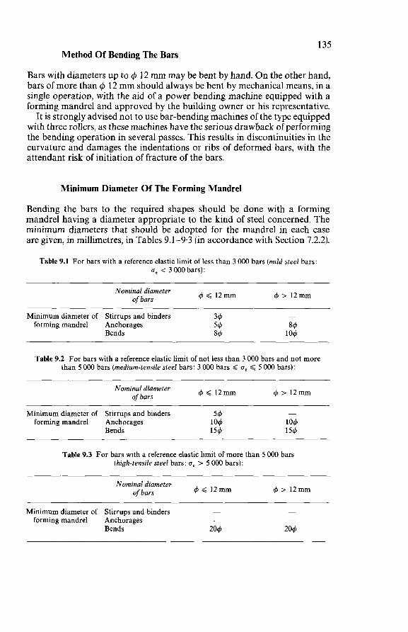
135 Method Of Bending The Bars
Bars with diameters up to 4 12 mm may be bent by hand. O n the other hand, bars of more than 4 12 mm should always be bent by mechanical means, in a single operation, with the aid of a power bending machine equipped with a forining mandrel and approved by the building owner or his representative. It is strongly advised not to use bar-bending machines of the type equipped
with three rollers, as these machines have the serious drawback of performing the bending operation in several passes. This results in discontinuities in the curvature and damages the indentations or ribs of deformed bars, with the attendant risk of initiation of fracture of the bars.
Minimum Diameter Of The Forming Mandrel
Bending the bars to the required shapes should be done with a forming mandrel having a diameter appropriate to the kind of steel concerned. The minimum diameters that should be adopted for the mandrel in each case are given, in millimetres, in Tables 9.1-9.3 (in accordance with Section 7.2.2).
Table 9.1 For bars with a reference elastic limit of less than 3 O00 bars (mild steel bars: u, < 3 O00 bars):
Nominal diameter oibars 4 < 1 2 m m
Minimum diameter of Stirrups and binders 34 forming mandrel Anchorages 54
Bends 84
Table 9.2 For bars with a reference elastic limit of not less than 3 O00 bars and not more than 5 O00 bars (medium-tensile steel bars: 3 O00 bars f ue < 5 000 bars):
Nominal diameter of bars 4 < 1 2 m m 4 > 1 2 m m
- Minimum diameter of Stirrups and binders 54 forming mandrel Anchorages 104 104
Bends 154 154
Table 9.3 For bars with a reference elastic limit of more than 5 O00 bars (high-tensile steel bars: 6, > 5 O00 bars):
Nominal diameter of bars 4 f 12mm 4 > 12mm
Minimum diameter of Stirrups and binders - - forming mandrel Anchorages - -
Bends 204 204
136 Table 9.3 does not envisage the use of these steels for anchorages formed by
bending nor for stirrups and binders. For these steels the minimum mandrel diameter can permissibly be reduced if the supplier of the steel explicitly guarantees the steel as being suitable for this, but the mandrel diameters adopted must on no account be less than those in Table 9.2. These diameters may in each case be rounded off to the actual diameter
of the available forming mandrel, provided that this is larger than the minimum indicated.
Speed Of Bending
The speed of bending applied to the bars should take account of the nature of the steel and of the ambient temperature. It should be determined by means of preliminary tests, especially in the case of medium-tensile and high-tensile bars.
If the ambient temperature is below + 5" C, additional precautions should be taken: the speed of bending should then not only be greatly reduced, but the diameters of the forming mandrels should be increased as well (in relation to the values stated in the tables in Section 9.2.2).
If the ambient temperature is below - 5" C, no bar-bending should be done.
Prohibition To Straighten Bent Bars
Straightening bent bars is always very risky. Hence no systematic straighten- ing of bends in bars should be allowed. If a curve or bend has to undergo a correction in situ, this should be done
by increasing the curvature, never by decreasing it, not even partially. The fact that a medium-tensile or high-tensile steel bar satisfies the to-and-
fro bend test (Section 9.2.1) does not authorise the contractor to perform such operations on the reinforcing bars actually used in the job.
9.2.3 WELDING OF REINFORCEMENT
Welding of the reinforcement can be envisaged only for bars having an elastic limit of less than 5 O00 bars and on condition that welding will not reduce the strength nor entail a risk of brittle fracture of the bars.
Method Of Welding
The method of welding should be agreed among the building owner, the contractor and the manufacturer of the steel. The latter should provide all references and justifications that may be considered necessary. In any case the method of welding should conform to the requirements
of Section 7.2.4 concerning welded splices : (a) either by means of butt welds produced by flash welding;
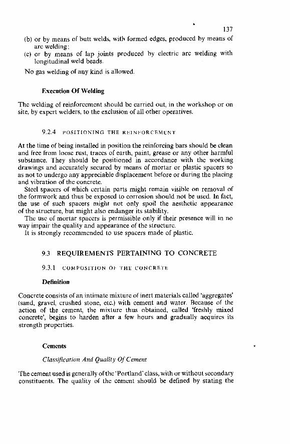
&
137 (b) or by means of butt welds, with formed edges, produced by means of
(c) or by means of lap joints produced by electric arc welding with
N o gas welding of any kind is allowed.
arc welding;
longitudinal weld beads.
Execution Of Welding
The welding of reinforcement should be carried out, in the workshop or on site, by expert welders, to the exclusion of all other operatives.
9.2.4 POSITIONING THE REINFORCEMENT
At the time of being installed in position the reinforcing bars should be clean and free from loose rust, traces of earth, paint, grease or any other harmful substance. They should be positioned in accordance with the working drawings and accurately secured by means of mortar or plastic spacers so as not to undergo any appreciable displacement before or during the placing and vibration of the concrete. Steel spacers of which certain parts might remain visible on removal of
the formwork and thus be exposed to corrosion should not be used. In fact, the use of such spacers might not only spoil the aesthetic appearance of the structure, but might also endanger its stability. The use of mortar spacers is permissible only if their presence will in no
way impair the quality and appearance of the structure. It is strongly recommended to use spacers made of plastic.
9.3 REQUIREMENTS PERTAINING TO CONCRETE
9.3.1 COMPOSITION OF THE CONCRETE
Definition
Concrete consists of an intimate mixture of inert materials called ‘aggregates’ (sand, gravel, crushed stone, etc.) with cement and water. Because of the action of the cement, the mixture thus obtained, called ‘freshly mixed concrete’, begins to harden after a few hours and gradually acquires its strength properties.
Cements
Classification And Quality Of Cement
The cement used is generally of the ‘Portland class, with or without secondary constituents. The quality of the cement should be defined by stating the
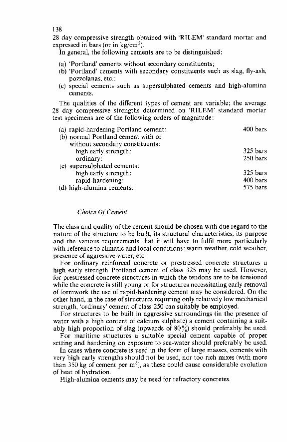
138 28 day compressive strength obtained with ‘RILEM’ standard mortar and expressed in bars (or in kg/cm2). In general, the following cements are to be distinguished:
(a) ‘Portland cements without secondary constituents; (b) ‘Portland’ cements with secondary constituents such as slag, fly-ash,
(c) special cements such as supersulphated cements and high-alumina
The qualities of the different types of cement are variable; the average 28 day compressive strengths determined on ‘RILEM’ standard mortar test specimens are of the following orders of magnitude:
400 bars
pozzolanas, etc. ;
cements.
(a) rapid-hardening Portland cement: (b) normal Portland cement with or
without secondary constituents : high early strength: 325 bars ordinary : 250 bars
high early strength: 325 bars rapid-hardening : 400 bars
(d) high-alumina cements: 575 bars
(c) supersulphated cements:
Choice Of Cement
The class and quality of the cement should be chosen with due regard to the nature of the structure to be built, its structural characteristics, its purpose and the various requirements that it will have to fulfil more particularly with reference to climatic and local conditions : warm weather, cold weather, presence of aggressive water, etc. For ordinary reinforced concrete or prestressed concrete structures a
high early strength Portland cement of class 325 may be used. However, for prestressed concrete structures in which the tendons are to be tensioned while the concrete is still young or for structures necessitating early removal of formwork the use of rapid-hardening cement may be considered. O n the other hand, in the case of structures requiring only relatively low mechanical strength, ‘ordinary’ cement of class 250 can suitably be employed. For structures to be built in aggressive surroundings (in the presence of
water with a high content of calcium sulphate) a cement containing a suit- ably high proportion of slag (upwards of 80 %) should preferably be used. For maritime structures a suitable special cement capable of proper
setting and hardening on exposure to sea-water should preferably be used. In cases where concrete is used in the form of large masses, cements with
very high early strengths should not be used, nor too rich mixes (with more than 350 kg of cement per m3), as these could cause considerable evolution of heat of hydration. High-alumina cements may be used for refractory concretes.
139 For structures whose exposed concrete surfaces are required to have an
architectural or decorative character it is advisable to use white Portland cement (normal or rapid-hardening).
Storage Of Cement
Cement may be stored either in bags or drums or, alternatively, in silos or bins (storage in bulk). It should be kept protected from the weather and more particularly from moisture. Storage in bags or drums should be sys- tematically organised, so as to make sure that the cement in some of the bags or drums will not be kept in storage for an excessively long time before use and thus undergo too much ageing.
Aggregates
Granulometric Classijìcation
The granulometric class of an aggregate (sand, gravel, crushed stone) is defined by two dimensions do and d,, corresponding respectively to the smallest and the largest of the particles of which that aggregate consists. An aggregate is, by definition, of the class do/d, if, for d, > 2do, the following values are obtained:
(a) a residue of less than 10 % on the sieve with apertures dM ; (b) less than 10% passing the sieve with apertures do; (c) less than 3 % passing the sieve with apertures $do. Aggregates can be subdivided into the categories shown in Table 9.4
and Figures 9.1 and 9.2.
Table 9.4
Classijìcation Sieve mesh Diameter of apertures of aggregates apertures (in mm) of round-hole screen (in mm)
Fines (or powders or fillers) < 0.08 Sands : fine 0.08-0.315
medium 0.3 15-1.25 coarse 1.25-5
Gravels : fine medium coarse
Crushed stone: fine medium coarse
6.3-10 10-16 16-25
25-40 40-63 63-100
140
Figure 9.1 Various sizes of sand: (left) fine sand (d,,<0-5 mm) (centre) mediuni sand (0.5<d,,<1-6mm) (right) coarse sand (I6<d,<5mm)
Figure 9.3. Various sizes of gravel (lefr) fine gravel (6.3 < d, < d, < IO mm) (centre) medium gravel (IO < d, < i6 mm) (right) coarse gravel (I6 < d, < I5 mm)
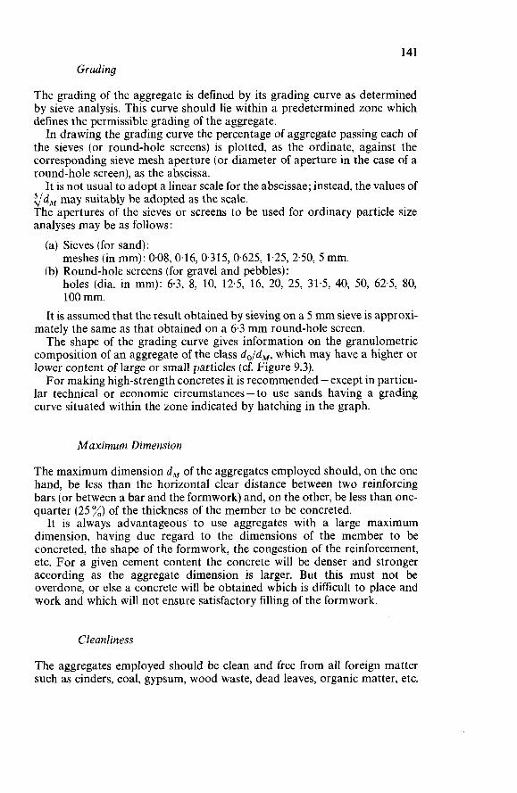
141 Grading
The grading of the aggregate is defined by its grading curve as determined by sieve analysis. This curve should lie within a predetermined zone which defines the permissible grading of the aggregate. In drawing the grading curve the percentage of aggregate passing each of
the sieves (or round-hole screens) is plotted, as the ordinate, against the corresponding sieve mesh aperture (or diameter of aperture in the case of a round-hole screen), as the abscissa. It is not usual to adopt a linear scale for the abscissae; instead, the values of
v d A f may suitably be adopted as the scale. The apertures of the sieves or screens to be used for ordinary particle size analyses may be as follows : (a) Sieves (for sand):
(b) Round-hole screens (for gravel and pebbles): meshes (in mm): 0.08, 0.16, 0.315, 0.625, 1.25, 2.50, 5 mm.
holes (dia. in mm): 6.3, 8, 10, 12.5, 16, 20, 25, 31.5, 40, 50, 62.5, 80, 100 mm.
It is assumed that the result obtained by sieving on a 5 mm sieve is approxi- mately the same as that obtained on a 6.3 mm round-hole screen. The shape of the grading curve gives information on the granulometric
composition of an aggregate of the class d,/d,, which may have a higher or lower content of large or small particles (cf. Figure 9.3). For making high-strength concretes it is recommended - except in particu-
lar technical or economic circumstances - to use sands having a grading curve situated within the zone indicated by hatching in the graph.
M a x i m u m Dimension
The maximum dimension d, of the aggregates employed should, on the one hand, be less than the horizontal clear distance between two reinforcing bars (or between a bar and the formwork) and, on the other, be less than one- quarter (25 %) of the thickness of the member to be concreted.
It is always advantageous. to use aggregates with a large maximum dimension, having due regard to the dimensions of the member to be concreted, the shape of the formwork, the congestion of the reinforcement, etc. For a given cement content the concrete will be denser and stronger according as the aggregate dimension is larger. But this must not be overdone, or else a concrete will be obtained which is difficult to place and work and which will not ensure satisfactory filling of the formwork.
Cleanliness
The aggregates employed should be clean and free from all foreign matter such as cinders, coal, gypsum, wood waste, dead leaves, organic matter, etc.
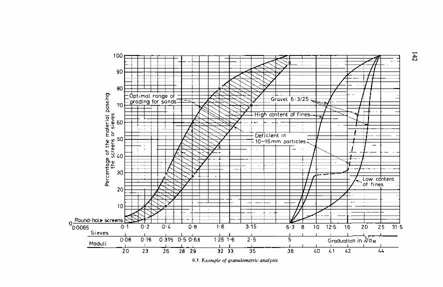
142
Ln
m - Lo N
O N
u3 r
x r 0
a3
w
m
< n n
r
m 6
U
3
N 3
r
6
ul u3 O
ct ct
N
U
r
U
3
U
m m u3 m
m
m N
m
o)
N
m N
W N
FI N
3
N
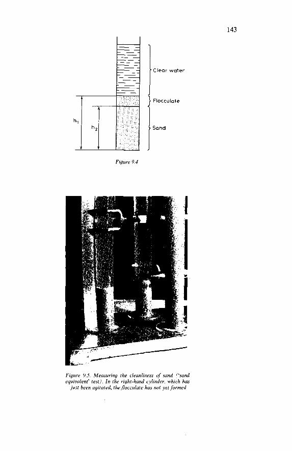
143
Figure 9.4
Clear water
Flocculate
Sand
Figure 9.5. Measuring the cleanliness of sand (‘sand equivalent’ test). In the right-hand cylinder, which has just been agitated, theflocculate has not yet formed
144 Gravel and pebbles should be free from clayey matter or adhering soil.
Sand should be free from fine clayey matter and should satisfy the so-called ‘sand equivalent’ test. The desirable optimum value of the sand equivalent (SE) if visual measurement is employed is: 75 <SE< 85. Measuring the cleanliness of the sand should be done by means of the
so-called ‘sand equivalent’ (SE) test (see Figures 9.4 and 9.5). A certain quantity of sand is put into a glass cylinder with a washing
solution based on calcium chloride, glycerine and formaldehyde and agitated. The liquid is then allowed to stand for 20 minutes. Next, with the aid of a graduated scale, the height to the top surface of the flocculate (turbid water) and the height to the top of the sand deposit are measured. If these heights are h, and h, respectively, the sand equivalent is:
h SE = 1002 hl
The height h, may be measured either ‘by eye’ directly with the aid of a rule (graduated scale) or ‘by piston’, i.e., on the rod of a weighted piston which is lowered on to the sand at the bottom of the cylinder and whereby generally a slightly smaller value for h, is obtained than ‘by eye’.
If the sand contains fine clayey matter, the values in Table 9.5 can be adopted for guidance.
Table 9.5
SE ‘by eye’ SE ‘by piston’
SE<65 SE < 60
65GSE <75 60<SE<70
75<SE <85 70s SE <80
SE 2 85 SE280
Nature And Shape
Nature and quality of the sand
Clayey sand: risk of shrinkage or swelling; not suitable for high-strength concretes. Slightly clayey sand, sufficiently clean for making concretes of ordinary quality, unless shrinkage is something particularly to be avoided. Clean sand with low percentage of fine clayey matter, quite suitable for high-strength concretes (optimum value of SE = 75 by piston or 80 by eye). Very clean sand: because of the almost total absence of fine clayey particles the concrete may be deficient in plasticity; this should be compensated by increasing the water con- tent.
The aggregates used should either be natural sands, gravels and pebbles, or crushed materials produced from appropriate types of rock (see Figure 9.6). In particular, rock which is too friable or too soft (such as certain limestones) or which decomposes in contact with the air (such as certain porphyries) or by hydration (such as certain shales) must not be employed. O n the other hand certain blast furnace slags can, when crushed, permissibly be used.
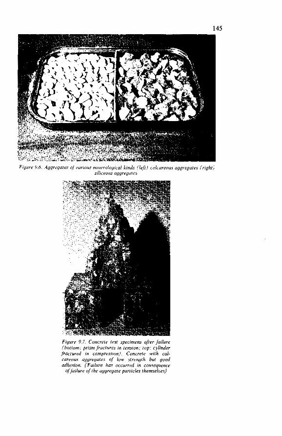
145
Figure 9.6. Aggregates of various mineralogical kinds (left) calcareous aggregates (right) siliceous aggregates
Figure 9.7. Concrete test specimens after failure (bottom: prism fractures in tension; top: cylinder fractured in compression). Concrete with cal- careous aggregates of low strength but good adhesion. (Failure has occurred in consequence of failure of the aggregate particles themselves)
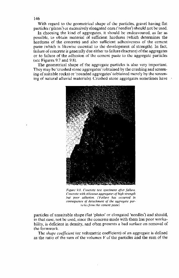
146 With regard to the geometrical shape of the particles, gravel having flat
particles (‘plates’) or excessively elongated ones (‘needles’) should not be used. In choosing the kind of aggregates, it should be endeavoured, as far as
possible, to obtain material of sufficient hardness (which determines the hardness of the concrete) and also sufficient adhesiveness of the cement paste (which is likewise essential to the development of strength). In fact, failure of concrete is generally due either to failure (fracture) of the aggregates or to failure of the adhesion of the cement paste to the aggregate particles (see Figures 9.7 and 9.8). The geometrical shape of the aggregate particles is also very important.
They may be ‘crushed stone aggregates’ (obtained by the crushing and screen- ing of suitable rocks) or ‘rounded aggregates’ (obtained merely by the screen- ing of natural alluvial materials). Crushed stone aggregates sometimes have ’
Figure 9.8. Concrete test specimens after failure. Concrete with siliceous aggregates of high strength but poor adhesion. (Failure has occurred in consequence of detachment of the aggregate par-
ticles from the cement paste)
particles of unsuitable shape (flat ‘plates’ or elongated ‘needles’) and should, in that case, not be used, since the concrete made with them has poor worka- bility, is deficient in density, and often presents a bad surface on removal of the formwork. The shape coefficient (or volumetric coefficient) of an aggregate is defined
as the ratio of the sum of the volumes V of the particles and the sum of the
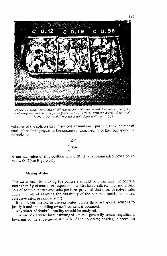
147
Figure 9.9. Graoel 16/25 mm of different shapes. (left) grauel with high proportion offlat and elongated particles: shape coefficient = 0-12 (centre) ordinary grawl: shape coef
ficieiit = 0.19 (right) rounded gravel: shape coefficient = 0-38
volumes of the spheres circumscribed around each particle, the diameter of each sphere being equal to the maximum dimension d of the corresponding particle, i.e. :
CV
A normal value of this coefficient is 0.20; it is recommended never to go below 0.15 (see Figure 9.9).
Mixing Water
The water used for mixing the concrete should be clean and not contain more than 5 g of matter in suspension per litre (mud, silt, etc.) nor more than 35 g of soluble matter and salts per litre, provided that these dissolved salts entail no risk of harming the durability of the concrete (acids, sulphates, corrosive salts, organic matter). It is not permissible to use sea water, unless there are special reasons to
justify it and the building owner’s consent is obtained. Any water of doubtful quality should be analysed. The use of sea water for the mixing of concrete generally causes a significant
lowering of the subsequent strength of the concrete; besides, it promotes
148 corrosion of the reinforcement and is liable to be particularly dangerous in heavily reinforced or in prestressed concrete. In any case it must be taken into consideration that the amount of calcium chloride introduced with the sea water is equivalent to about 2 % (by weight) of the cement.
Additives
Additives are special substances which are added in small quantities to mortars and concretes at the beginning of mixing and whose purpose is to modify some of the properties thereof. Special reasons must be adduced to justify the use of additives, and the building owner’s consent must be obtained. The method of using the additive and the amount to be added should be
specified by the building owner and strictly conformed to. Special precau- tions must be taken to ensure that the additive is uniformly distributed throughout the mix. Additives are available in the form of powders or liquids which are added
at the start of mixing, in order to ensure uniform distribution of these substances. In the main, the following kinds of additives are to be distinguished: Plasticisers and wetting agents: By using these additives it is possible to
reduce the quantity of water and yet obtain the same plasticity of the mix or, alternatively, to increase the plasticity (and thus achieve better workability of the concrete) without increasing the water content.
Air-entraining agents: These additives, which are sometimes mixed with the cement in advance (air-entraining cement) cause large numbers of very small air bubbles to be incorporated into the concrete; these bubbles increase the plasticity of the freshly mixed concrete and improve the frost resistance of the hardened concrete.
Setting retarders: These may be necessary in cases where the setting of the concrete has to be retarded (e.g., at construction joints where cbncreting is temporarily stopped, exposing the aggregate by scrubbing the concrete surface, concreting in very warm weather).
Setting accelerators: Additives of this type may have to be used in cases where the formwork must be removed soon or where concreting is done in cold weather. A commonly used accelerator is calcium chloride, but as it entails a serious risk of corrosion of the reinforcement, its use is strictly limited. Some additives may: (a) either entail a danger of corroding the reinforcement or other metal
objects embedded in the concrete (heating coils, plumbing, etc.); (b) or adversely affect other properties (hardening accelerators cause
increased shrinkage, antifreeze agents cause reduction in strength, etc.).
These dangers should be duly taken into consideration when choosing
Besides, it must always be remembered that an additive must be added an additive.
149 only in small quantity and that it must be uniformly distributed. Most adverse effects attributable to the use of additives are in fact due to excessive amounts being employed (which is something that is often difficult to supervise on the site) or to lack of perfect homogeneity in mixing the additive with the concrete. Because of the serious risk of corrosion of the reinforcement, calcium
chloride and additives containing chlorides are not allowed to be used for making mortars and concretes used for the following structures or structural components: (a) prestressed concrete structures; (b) tanks and containers; (c) floors in which the main or the secondary reinforcement of the joists
(d) floors in which heating coils are incorporated; (e) concrete members treated by steam curing. For other reinforced concrete structures the use of calcium chloride or
additives containing chlorides is permissible only on the following conditions :
(1) Calcium chloride and additives containing chlorides must not be used with lime-based slag cements, nor with high-alumina cements, nor with supersulphated cements. For cements other than Portland cements it is necessary first to carry
out a setting test and, if necessary on account of the conditions of use of the concrete, a short-term compressive test, because the results vary according to the nature and proportions of the constituents and also according to the proportion of chlorides that may have been incorporated with the cement at manufacture. (2) The maximum permissible amounts of calcium chloride -ratios of
the weight of commercial calcium chloride (flakes containing 75-77 % of CaCl,) to the weight of cement used -are as follows : (a) 2% for mortars, for plain (unreinforced) concretes, and for reinforced
(b) 1 % for reinforced concrete with at least 2 cm of cover to the reinforce-
The maximum percentages indicated relate to the total quantity of chlorides, i.e., they include the quantity of chlorides (if any) that is already present in the cement or in some other constituent of the concrete or in any other additive used in conjunction with calcium chloride. So if another additive is used together with calcium chloride, it is necessary
to satisfy oneself that this other additive does not contain chlorides or, if it does, to take this into account and check that the total quantity of chlorides will not - having regard to other possible sources of introduction of chlorides into the mix - exceed the permitted maximum percentage. Calcium chloride and additives containing chlorides should be protected
from moisture during storage. These substances should never be incorporated directly into mortars and concretes. Whichever method of introducing them
consists of steel strips or sheets;
concretes with at least 4 cm of cover to the reinforcement;
ment.
.
1 50 into the mix is employed (first dissolving the chloride or additive in water and then adding this solution to the mixing water, or directly putting the chloride or additive into the mixing water), it is necessary always to satisfy oneself that the substance is completely dissolved and to take the necessary steps to ensure that the concentration is as uniform as possible. In particular, a stirrer should be used for homogenising the solution at all stages, both when a preliminary solution is prepared and when the substances are mixed with the water for making the concrete. The following method is recommended for using calcium chloride as the
sole additive containing chloride: First, a solution of calcium chloride in water should be prepared as follows : (a) obtain a tank of more than 100 litres capacity; (b) put in 80 litres of water and mark the level of this water with an
indelible mark; (c) then slowly add the contents of a bag of calcium chloride while vigor-
ously and continuously stirring the water to ensure that the flakes will dissolve completely: in this way 100 litres of a solution is obtained whose strength corresponds to 5 kg of flakes per litre;
(d) now put into the concrete mixer, which should be running and already have had at least half the required quantity of mixing water put into it, as many times 2 litres of solution as there are kilogrammes of chloride to be introduced into the concrete; for example:
1 litre of solution per 50 kg bag of cement if the specified content of chloride is 1 % of the weight of the cement (i.e., 0.5 kg of chloride per 50 kg of cement);
(e) add the rest of the mixing water; (f) then run the mixer for a sufficient length of time to obtain a good mix
(at least 13 minutes or more, depending on the efficiency of the mixer employed).
If calcium chloride or an additive containing chlorides is used in conjunc- tion with another additive, it is necessary to satisfy oneself that the two substances are not incompatible, i.e., that the two additives will not, on being mixed together, give rise to chemical reactions liable to cancel the desired effect; in particular, they must not cause any insoluble salt to be precipitated.
Batching The Cement
The concrete mix should normally contain between 250 and 450kg of cement per cubic metre of concrete as finally present in the structure. Departure from this requirement will call for special justification and the building owner’s approval. For ordinary reinforced concrete structures the concrete should contain 350 kg of cement per cubic metre. For reinforced concrete structures which are required to have special properties of water-
151 tightness and density, and for prestressed concrete structures, the concrete should contain 450 kg of cement per cubic metre. The mix proportions of a concrete can be determined by a number of
theoretical or experimental methods which yield mix formulae from which, in each case, the quantities of each of the constituents (including the water) making up the composition of one cubic metre of concrete as finally present in the structure can be calculated. The concrete is said to be batched (or proportioned) ‘by volume’ if those
quantities are measured by volume, and batched ‘by weight’ if they are measured by weight, the latter being the preferable method. The cement content most commonly adopted for reinforced concrete
structures exposed to the weather is 350 kg/m3. However, this can permissibly be varied on the basis of the following considerations: (a) the strength of a concrete will be higher according as the cement
content is higher; (b) increasing the cement content will increase the risk of shrinkage and
cracking of the concrete and will cause more heat of hydration to be evolved during setting;
(c) for equal strength of the concrete, the cement content can be reduced if the dimension d of the aggregates is increased; this reduction may be applied proportionally to yd.
As an empirical rule, the cement content of reinforced concrete should not be less than (550/7d) (in kg/m3 of concrete as finally present in the structure), i.e. :
350 kg/m3 for d = 10mm 315 kg/m3 for d = 16mm 290 kg/m3 for d = 25 mm 250 kg/m3 for d = 50 mm 220 kg/m3 for d = 100 mm
Batching The Aggregates
The quantities of aggregates in a concrete mix are defined in terms of the proportions by volume or, preferably, by weight of the various aggregates making up the composition of one cubic metre of concrete as finally present in the structure. These proportions should be specially determined by experimental methods (trial and error), unless the contractor has at his disposal, for similar materials used under identical conditions, a set of reliable practical rules confirmed by long experience with those materials. The relative proportions of sand and gravel should be such that the
concrete has satisfactory homogeneity without any risk of segregation. In most cases the choice and proportions of the aggregates will be deter-
mined by means of investigations in the laboratory, with due regard to the nature of the structure, its structural features, the required strengths, the nature, shape and grading of the available aggregates, etc. For guidance the
152 following method, called the ‘GIS coefficient method’ may be employed in normally encountered cases.
G/S Coefficient Method (see Figure 9.10)
This method of concrete mix design is purely empirical and is based on a large number of tests performed on a wide variety of concretes made in the laboratory. In the most frequent case of a concrete mix comprising coarse aggregate
(gravel, weight G) and fine aggregate (sand, weight S) the proportions are determined by the ratio GIS, once the cement content C has been decided on the basis of the information given in the preceding section. In general, the value normally adopted for G/S is 2.0. It may, however,
be varied between 1.5 and 2.4, having regard to the following considerations:
(a) The higher G/S is, the higher will be the mechanical strength of the concrete; against this, however, the concrete is more liable to segregate and present difficulties in placing because of deficient workability or because of considerable wall effect.
(b) For a very plastic concrete mix, with high content of mortar and good workability, giving surfaces that present a good appearance on removal of the formwork, but not producing a concrete of exceptional strength, the following values may be adopted:
1.5 < G/S< 1.7 (c) For normal concrete, as used in ordinary reinforced concrete construc-
tion, with plasticity that may be varied according to the nature of the structure by varying the amount of water in the mix, of fair workability and giving good strengths, the following values may be adopted:
1.8<G/S<2.0 (d) For high-density concrete, of ‘stiff consistency when freshly mixed,
producing high strengths but liable to segregate and requiring certain precautions at the time of concreting (compaction by powerful vibra- tion, in particular), the following values may be adopted:
2.0 < G/S < 2.2 (and exceptionally : 2.4) (e) In the case of rounded aggregates the above values of G/S are valid,
but if crushed stone aggregates are employed, slightly lower values should be adopted to GIS: for example, the above values should be reduced by: 0.1 in the case of rounded sand and crushed coarse aggregate; 0.2 in the case of crushed fine aggregate and crushed coarse aggregate.
When the value of G/S has been chosen, as also the quantity of cement in the mix, the respective quantities of gravel and sand can be determined by considering that the total weight (C+G+S+water) must be equal to the weight of one cubic metre of concrete as finally present in the structure.
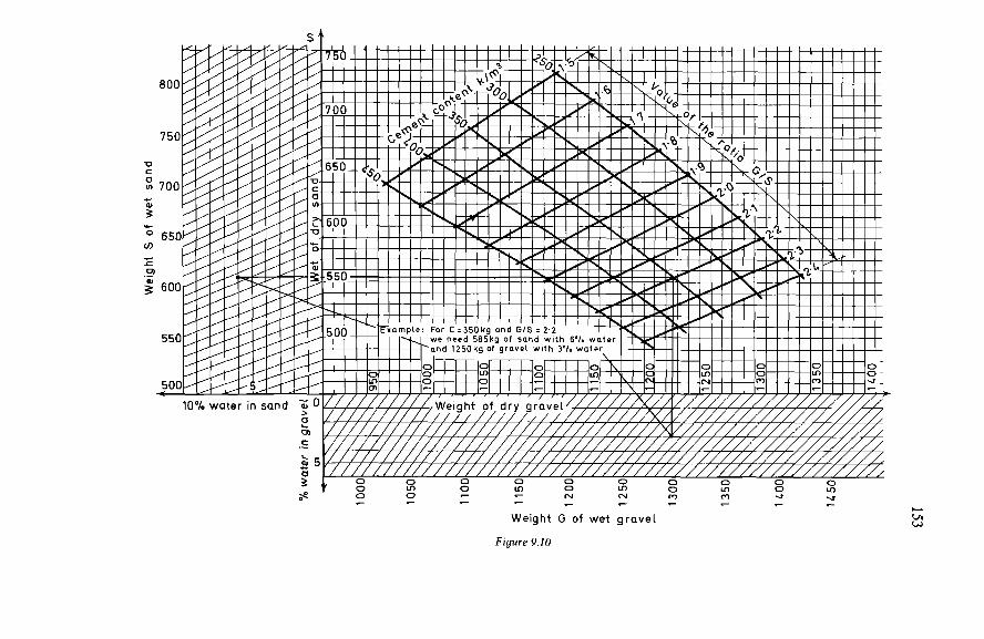
153
154 With the aid of the accompanying graph these quantities can readily be
calculated for the normal case where two aggregates (coarse and fine) are used in the mix: sand 0/5mm and gravel 5/25mm, both with a specific gravity o = 2.6. If the aggregates have a specific gravity differing from 2.6, the weights read from the graph should be corrected by multiplying them by o/26 The weights indicated are dry weights, i.e., for the completely dry materials.
However, if the water contents of the aggregates have been measured (or estimated), the actual moist weights of the materials to be put into the concrete mixer can be read directly from the oblique scales. The total weight G of gravel, thus determined, remains approximately
valid also in a case where several coarse aggregates are employed in the mix. The respective proportions of each of these (G,, G,, G,) must be such that G, + G, + G, = G. The weights G,, G,, G, should be so distributed that the grading curve of the mixture G, + G, + G, is a smoothly continuous curve. To proceed from batching by weight to batching by volume, the weights
of the aggregates employed should be divided by the respective bulk densities of these aggregates. When the theoretical ‘mix design’ (determination of the proportions of
constituents in the mix) has thus been carried out, the following should be determined by means of a preliminary test: (a) the quantity of water needed for obtaining the desired plasticity; (b) the density of the freshly placed concrete, whereby the necessary
corrections can be applied to the theoretical weights of the aggregates, so that the mix formula, corrected in this way, does indeed correspond to a cubic metre of concrete as finally present in the structure; the weight of this cubic metre must be equal to the sum of the weights of the constituents (including the water) as given by the mix formula;
(c) the strength of the concrete made in this way.
Quantity Of Water And Consistency Of The M i x
The quantity of water (total water) is determined for aggregates assumed to be dry and for a cubic metre of concrete as finally present in the structure. If the aggregates employed contain a certain amount of water, their water content (additional water) should be estimated and deducted from the required total water: thus the quantity of water to be added during mixing is found. The mix should contain enough water to give the plasticity compatible
with good workability, but not too much water, as the strength of the concrete becomes lower with increasing water content of the mix. O n no account must water be added to a concrete mix that is considered to be too dry after leaving the mixer. The desired consistency can be defined on the basis of the slump test
(see Figure 9.1 1). The water content of a concrete can, and must, be defined only in terms of
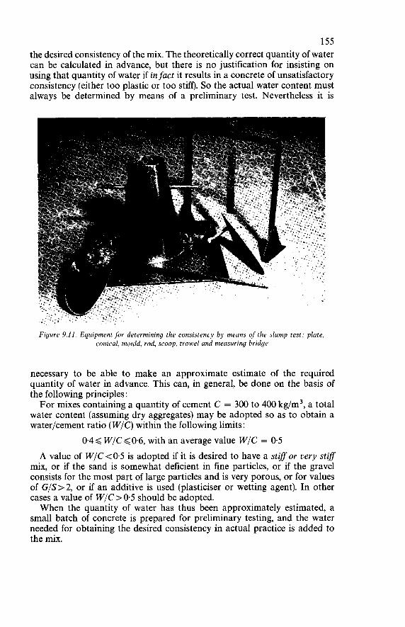
155 the desired consistency of the mix. The theoretically correct quantity of water can be calculated in advance, but there is no justification for insisting on using that quantity of water if infuct it results in a concrete of unsatisfactory consistency (either too plastic or too stiff). So the actual water content must always be determined by means of a preliminary test. Nevertheless it is
Figure 9.11. Equipment for determining the consistency by means of the slump test: plate, conical, mould, rod, scoop, trowel and measuring bridge
necessary to be able to make an approximate estimate of the required quantity of water in advance. This can, in general, be done on the basis of the following principles : For mixes containing a quantity of cement C = 300 to 400 kg/m3, a total
water content (assuming dry aggregates) may be adopted so as to obtain a waterfcement ratio (W/C) within the following limits :
0.4 < W/C < 0.6, with an average value W / C = 0.5 A value of W/C<O.5 is adopted if it is desired to have a stiff or very stif
mix, or if the sand is somewhat deficient in fine particles, or if the gravel consists for the most part of large particles and is very porous, or for values of G/S>2, or if an additive is used (plasticiser or wetting agent). In other cases a value of W / C > 0.5 should be adopted. When the quantity of water has thus been approximately estimated, a
small batch of concrete is prepared for preliminary testing, and the water needed for obtaining the desired consistency in actual practice is added to the mix.
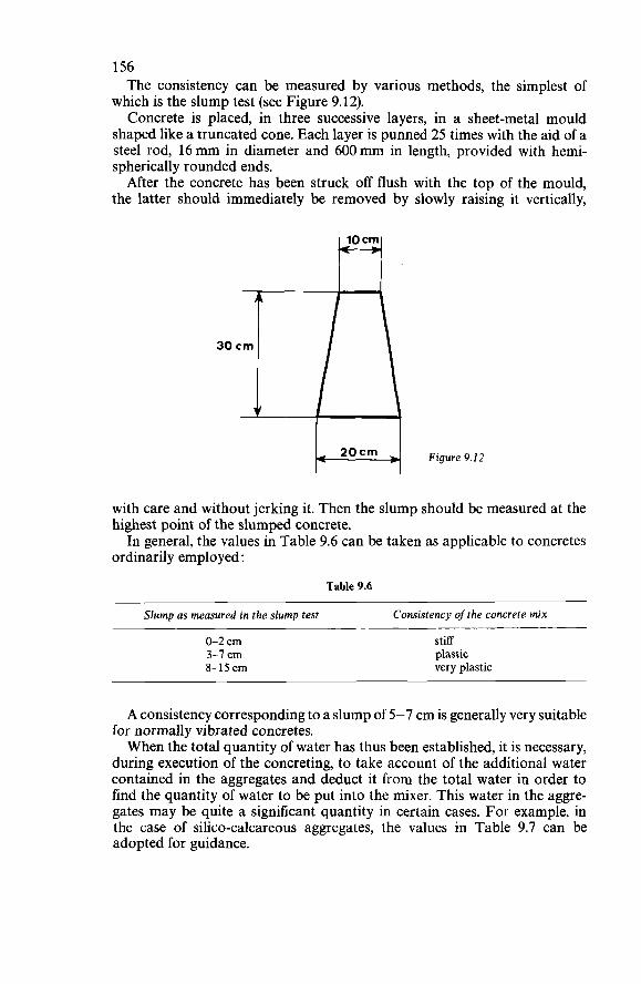
156 The consistency can be measured by various methods, the simplest of
which is the slump test (see Figure 9.12). Concrete is placed, in three successive layers, in a sheet-metal mould
shaped like a truncated cone. Each layer is punned 25 times with the aid of a steel rod, 16 mm in diameter and 600 mm in length, provided with hemi- spherically rounded ends. After the concrete has been struck off flush with the top of the mould,
the latter should immediately be removed by slowly raising it vertically,
H Figure 9.12 with care and without jerking it. Then the slump should be measured at the highest point of the slumped concrete. In general, the values in Table 9.6 can be taken as applicable to concretes
ordinarily employed:
Table 9.6
Slump as measured in the slump test Consistency of the concrete mix
0-2 c m 3-7 cm 8-15 c m
stiff plastic very plastic
A consistency corresponding to a slump of 5-7 cm is generally very suitable for normally vibrated concretes. When the total quantity of water has thus been established, it is necessary,
during execution of the concreting, to take account of the additional water contained in the aggregates and deduct it from the total water in order to find the quantity of water to be put into the mixer. This water in the aggre- gates may be quite a significant quantity in certain cases. For example, in the case of silico-calcareous aggregates, the values in Table 9.7 can be adopted for guidance.
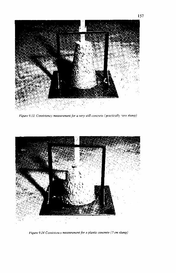
157
Figure 9.13. Consistency measurement for a very still concrete (practically zero slump)

158
Figure 9.15. Consistency measurement for a very plastic concrete (12 c m slump)
Figure 9.16. Judging the consistency by the feel. With plastic consistency it should still he possible tofòrm a ball in the hand (7 c m slump)
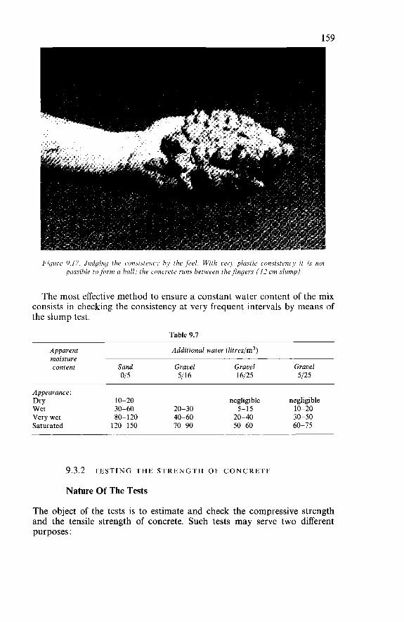
159
Figure 9.17. Judging rhe consistericy by the feel. With w r y plastic corisisteiicy it is not possible to /orin ci hall; ihe corici'etc runs between the$ngers (17 ctn sliirnp)
The most effective method to ensure a constant water content of the mix consists in checking the consistency at very frequent intervals by means of the slump test.
Table 9.7
Apparent Additional water (litreslm') moisture content Sand Gravel Gravel Gravel
015 5/16 16/25 5/25
Appearance: Dry Wet 30-60 20-30 5-15 10-20 Very wet 80-120 40-60 20-40 30-50 Saturated 120- 150 70-90 50-60 60-75
10-20 negligible negligible
9.3.2 TESTING THE STRENGTH OF CONCRETE
Nature Of The Tests
The object of the tests is to estimate and check the compressive strength and the tensile strength of concrete. Such tests may serve two different purposes :
160 Control
The object of ‘control tests’ is to control, i.e., keep a check on, the intrinsic strength of the concrete as manufactured, independently of the subsequent conditions of handling, placing, vibration, curing and storage. Control tests are performed on specimens taken at the mixer and stored
under standardised conditions. These tests are more particularly used for checking that the intrinsic properties of the concrete conform to the specifica- tions and to detect any defects in the constituents (cement, aggregates, additives) or even possible errors in batching.
informat ion
The object of ‘information tests’ is to estimate as closely as possible the strength of the concrete in the actual structure. Information tests are performed on specimens taken at the site during the
placing of the concrete in the formwork and stored under conditions which are as similar as possible to those of the structure itself. These tests are used more particularly for deciding whether it is suitable or safe to remove formwork or centring, to handle a concrete member, or to apply loading or prestress to a structure. All operations necessitated by the tests should be performed by suitably
skilled personnel.
Sampling
Sampling should be carried out in such a way that samples which are truly representative of the concrete are obtained. For control tests, sampling should be done at the mixer, the concrete
being taken as it leaves the mixer half-way through the discharge of a batch. For information tests, sampling should be done at the point of placing
the concrete, at the moment when it is being discharged into the formwork, and should comprise at least three samples taken at different points far from :he edges of the mass, where partial segregation is liable to occur. The amount of concrete taken in the samples should correspond to at least
one and a half times the volume of the test specimens to be made. The samples may be remixed, if necessary, on a non-absorbent surface so as to ensure the homogeneity of the concrete. They should be carefully protected from sun and rain; the test specimens should be made as soon as possible after the samples have been taken.
Moulds For Specimens
Cylindrical moulds for making test specimens should be of non-absorbent material and be sufficiently rigid to undergo no deformation during the
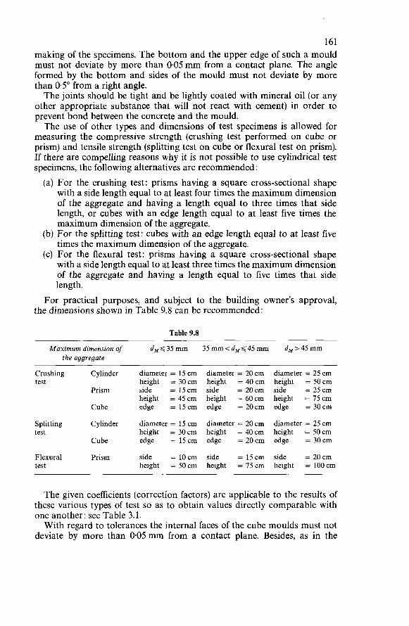
161 making of the specimens. The bottom and the upper edge of such a mould must not deviate by more than 0.05mm from a contact plane. The angle formed by the bottom and sides of the mould must not deviate by more than 0.5" from a right angle. The joints should be tight and be lightly coated with mineral oil (or any
other appropriate substance that will not react with cement) in order to prevent bond between the concrete and the mould. The use of other types and dimensions of test specimens is allowed for
measuring the compressive strength (crushing test performed on cube or prism) and tensile strength (splitting test on cube or flexural test on prism). If there are compelling reasons why it is not possible to use cylindrical test specimens, the following alternatives are recommended: (a) For the crushing test: prisms having a square cross-sectional shape
with a side length equal to at least four times the maximum dimension of the aggregate and having a length equal to three times that side length, or cubes with an edge length equal to at least five times the maximum dimension of the aggregate.
(b) For the splitting test: cubes with an edge length equal to at least five times the maximum dimension of the aggregate.
(c) For the flexural test: prisms having a square cross-sectional shape with a side length equal to at least three times the maximum dimension of the aggregate and having a length equal to five times that side length.
For practical purposes, and subject to the building owner's approval, the dimensions shown in Table 9.8 can be recommended:
Table 9.8
Maximum dimension of dA,$35mm 35mm<dMg45mm d,,>45mm the aggregate
Crushing Cylinder test
Prism
Cube
Splitting Cylinder test
Cube
Flexural Prism test
diameter = 15 cm diameter = 20 cm diameter = 25 cm height = 30cm height = 40cm height = 50cm side = 15cm side = 20cm side = 25cm height = 45 cm height = 60cm height = 75cm edge = 15cm edge = 20cm edge = 30cm
diameter = 15 cm diameter = 20 cm diameter = 25 cm height = 30cm height = 40cm height = 50cm edge = 15cm edge = 20cm edge = 30cm
side = 10cm side = 15cm side = 20cm height = 50cm height = 75cm height = 100cm
The given coefficients (correction factors) are applicable to the results of these various types of test so as to obtain values directly comparable with one another: see Table 3.1. With regard to tolerances the internal faces of the cube moulds must not
deviate by more than 0.05mm from a contact plane. Besides, as in the
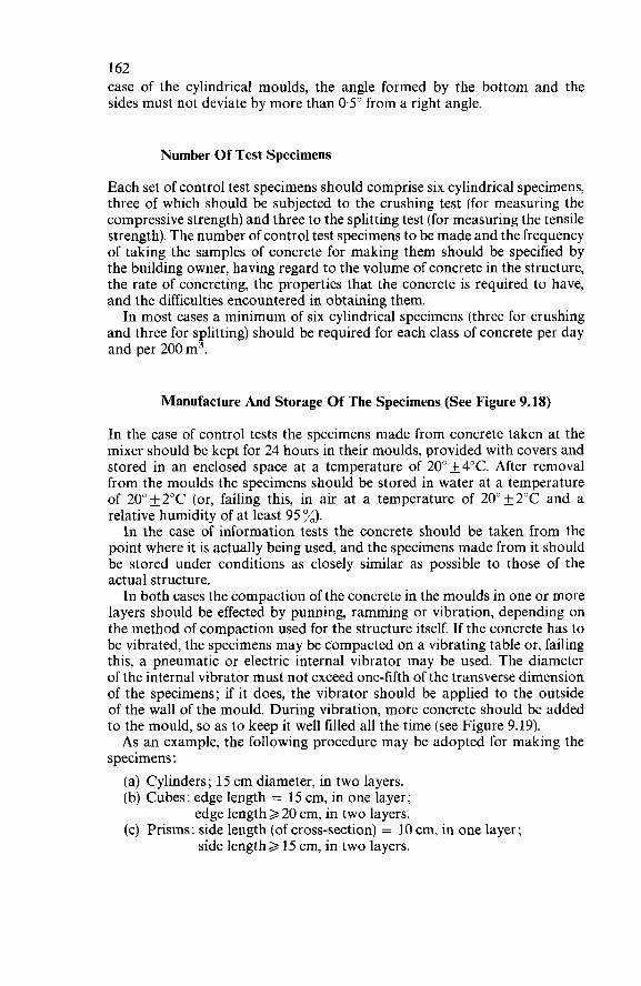
162 case of the cylindrical moulds, the angle formed by the bottom and the sides must not deviate by more than 0.5" from a right angle.
Number Of Test Specimens
Each set of control test specimens should comprise six cylindrical specimens, three of which should be subjected to the crushing test (for measuring the compressive strength) and three to the splitting test (for measuring the tensile strength). The number of control test specimens to be made and the frequency of taking the samples of concrete for making them should be specified by the building owner, having regard to the volume of concrete in the structure, the rate of concreting, the properties that the concrete is required to have, and the difficulties encountered in obtaining them. In most cases a minimum of six cylindrical specimens (three for crushing
and three for splitting) should be required for each class of concrete per day and per 200 m3.
Manufacture And Storage Of The Specimens (See Figure 9.18)
In the case of control tests the specimens made from concrete taken at the mixer should be kept for 24 hours in their moulds, provided with covers and stored in an enclosed space at a temperature of 20" f 4°C. After removal from the moulds the specimens should be stored in water at a temperature of 2Oo&2"C (or, failing this, in air at a temperature of 2O0&2"C and a relative humidity of at least 95 %). In the case of information tests the concrete should be taken from the
point where it is actually being used, and the specimens made from it should be stored under conditions as closely similar as possible to those of the actual structure. In both cases the compaction of the concrete in the moulds in one or more
layers should be effected by punning, ramming or vibration, depending on the method of compaction used for the structure itself. If the concrete has to be vibrated, the specimens may be compacted on a vibrating table or, failing this, a pneumatic or electric internal vibrator may be used. The diameter of the internal vibrator must not exceed one-fifth of the transverse dimension of the specimens; if it does, the vibrator should be applied to the outside of the wall of the mould. During vibration, more concrete should be added to the mould, so as to keep it well filled all the time (see Figure 9.19). As an example, the following procedure may be adopted for making the
specimens : (a) Cylinders; 15 cm diameter, in two layers. (b) Cubes: edge length = 15 cm, in one layer;
edge length > 20 cm, in two layers. (c) Prisms: side length (of cross-section) = 10 cm, in one layer;
side length > 15 cm, in two layers.
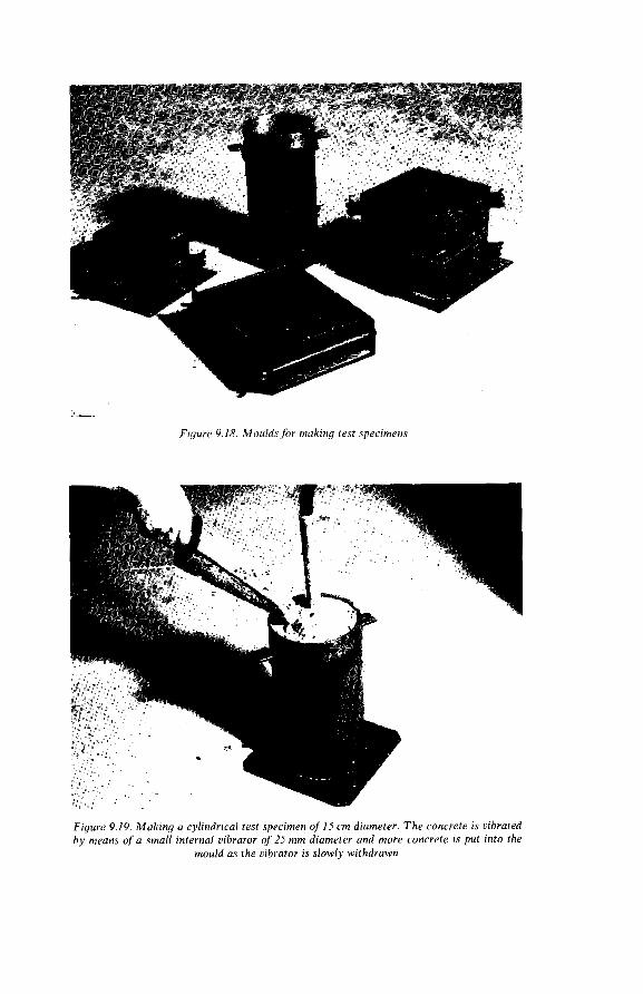
-.
Figure 9.18. Moulds for niaking test specimens
Figure 9.19. Making a cylindrical test specimen of 15 c m diameter. T h e concrete is vibrated by means ora small internal vibrator of 25 mm diameter and more concrete is put into the
mould as the uibiator is slowly withdrawn
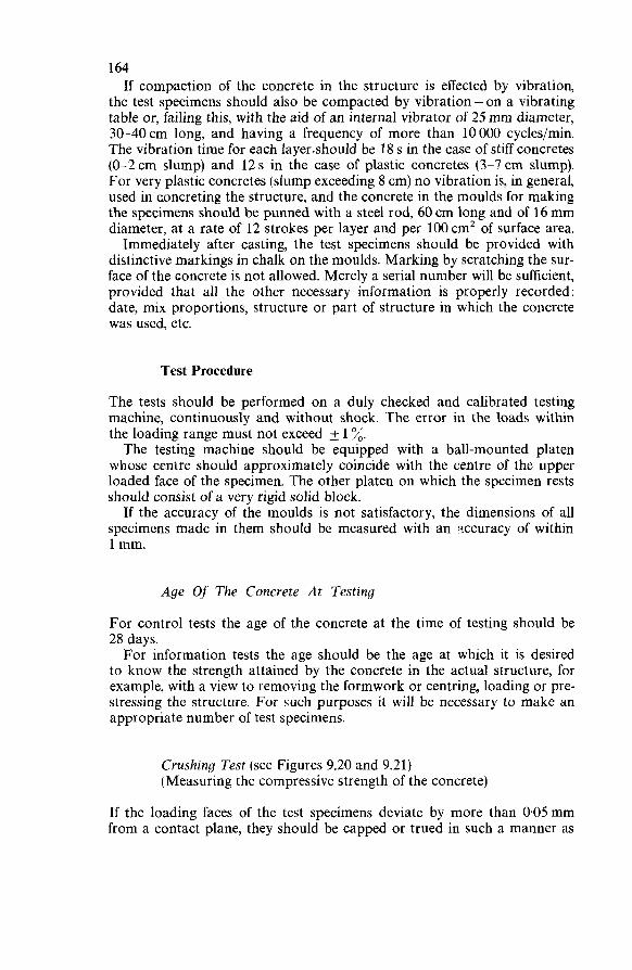
164 If compaction of the concrete in the structure is effected by vibration,
the test specimens should also be compacted by vibration - on a vibrating table or, failing this, with the aid of an internal vibrator of 25 mm diameter, 30-40cm long, and having a frequency of more than 10000 cycles/min. The vibration time for each 1ayer.should be 18 s in the case of stiff concretes (0-2cm slump) and 12s in the case of plastic concretes (3-7cm slump). For very plastic concretes (slump exceeding 8 cm) no vibration is, in general, used in concreting the structure, and the concrete in the moulds for making the specimens should be punned with a steel rod, 60 cm long and of 16 mm diameter, at a rate of 12 strokes per layer and per 100 cmz of surface area. Immediately after casting, the test specimens should be provided with
distinctive markings in chalk on the moulds. Marking by scratching the sur- face of the concrete is not allowed. Merely a serial number will be sufficient, provided that all the other necessary information is properly recorded : date, mix proportions, structure or part of structure in which the concrete was used, etc.
Test Procedure
The tests should be performed on a duly checked and calibrated testing machine, continuously and without shock. The error in the loads within the loading range must not exceed _+ 1 %. The testing machine should be equipped with a ball-mounted platen
whose centre should approximately coincide with the centre of the upper loaded face of the specimen. The other platen on which the specimen rests should consist of a very rigid solid block.
If the accuracy of the moulds is not satisfactory, the dimensions of all specimens made in them should be measured with an axcuracy of within 1 mm.
Age Of The Concrete At Testing
For control tests the age of the concrete at the time of testing should be 28 days. For information tests the age should be the age at which it is desired
to know the strength attained by the concrete in the actual structure, for example, with a view to removing the formwork or centring, loading or pre- stressing the structure. For such purposes it will be necessary to make an appropriate number of test specimens.
Crushing Test (see Figures 9.20 and 9.21) (Measuring the compressive strength of the concrete)
If the loading faces of the test specimens deviate by more than 0.05mm from a contact plane, they should be capped or trued in such a manner as
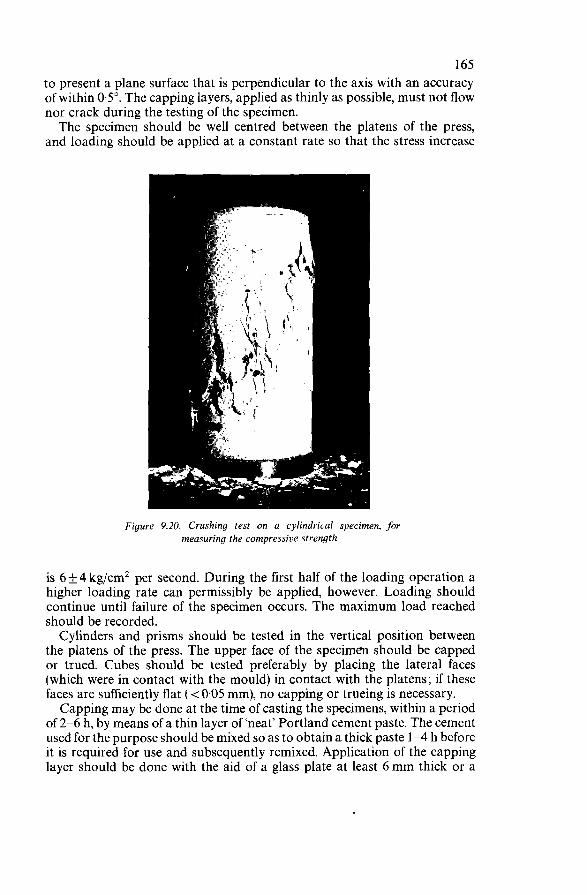
165 to present a plane surface that is perpendicular to the axis with an accuracy of within 0.5". The capping layers, applied as thinly as possible, must not flow nor crack during the testing of the specimen. The specimen should be well centred between the platens of the press,
and loading should be applied at a constant rate so that the stress increase
Figure 9.20. Crushing test on a cylindrical specimen. for measuring the compressive strength
is 6 f 4 kg/cm2 per second. During the first half of the loading operation a higher loading rate can permissibly be applied, however. Loading should continue until failure of the specimen occurs. The maximum load reached should be recorded. Cylinders and prisms should be tested in the vertical position between
the platens of the press. The upper face of the specimen should be capped or trued. Cubes should be tested preferably by placing the lateral faces (which were in contact with the mould) in contact with the platens; if these faces are sufficiently flat ( <0.05 mm), no capping or trueing is necessary. Capping may be done at the time of casting the specimens, within a period
of 2-6 h, by means of a thin layer of 'neat' Portland cement paste. The cement used for the purpose should be mixed so as to obtain a thick paste 1-4 h before it is required for use and subsequently remixed. Application of the capping layer should be done with the aid of a glass plate at least 6 mm thick or a
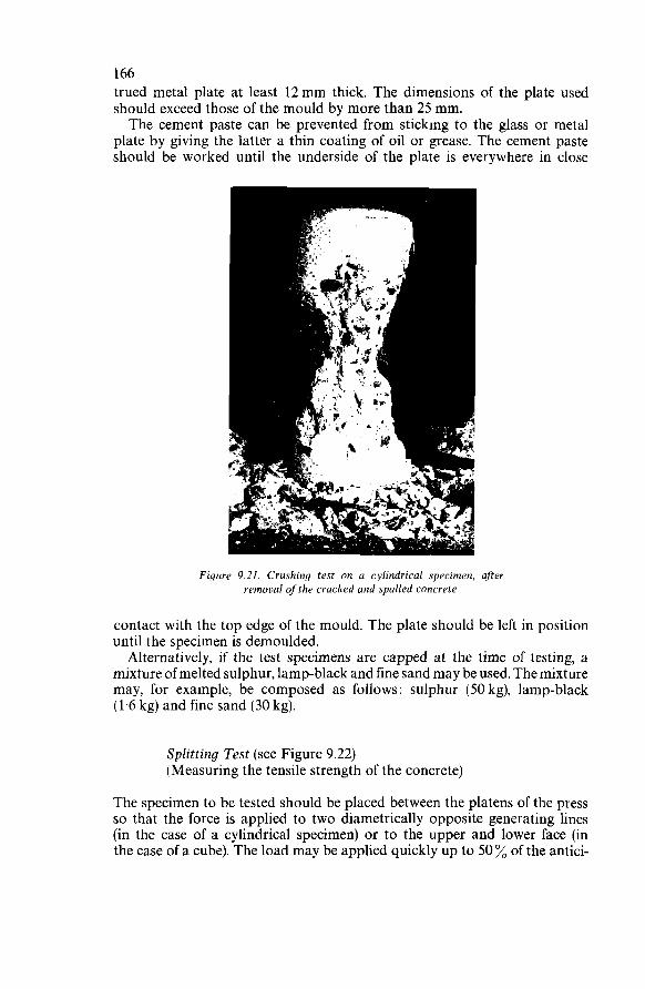
166 trued metal plate at least 12mm thick. The dimensions of the plate used should exceed those of the mould by more than 25 mm. The cement paste can be prevented from sticking to the glass or metal
plate by giving the latter a thin coating of oil or grease. The cement paste should be worked until the underside of the plate is everywhere in close
Figure 9.21. Crushing test on a cvlindrical specimen, after removal ojthe cracked and spalled concrete
contact with the top edge of the mould. The plate should be left in position until the specimen is demoulded. Alternatively, if the test specimens are capped at the time of testing, a
mixture of melted sulphur, lamp-black and fine sand may be used. The mixture may, for example, be composed as follows: sulphur (50 kg), lamp-black ( 1.6 kg) and fine sand (30 kg).
Splitting Test (see Figure 9.22) (Measuring the tensile strength of the concrete)
The specimen to be tested should be placed between the platens of the press so that the force is applied to two diametrically opposite generating lines (in the case of a cylindrical specimen) or to the upper and lower face (in the case of a cube). The load may be applied quickly up to 50 % of the antici-
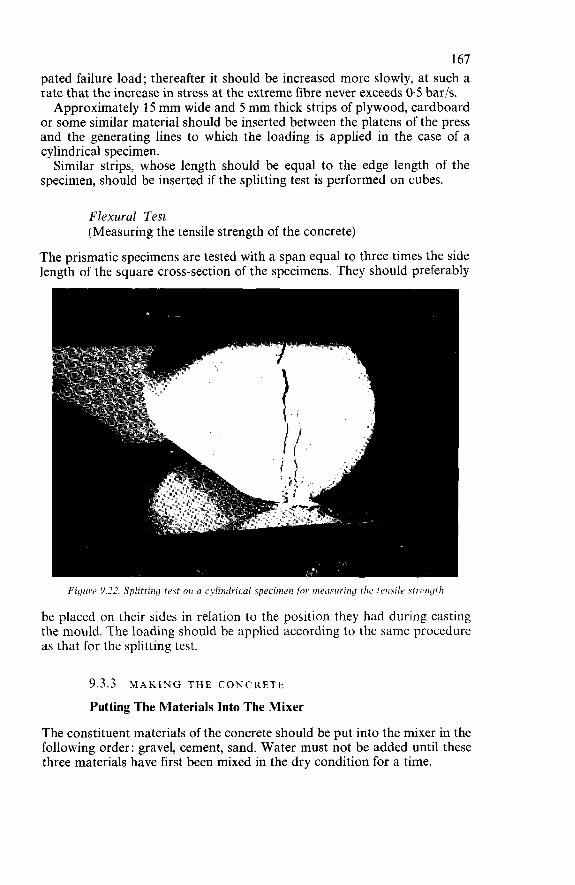
167 pated failure load; thereafter it should be increased more slowly, at such a rate that the increase in stress at the extreme fibre never exceeds 0.5 bar/s. Approximately 15 mm wide and 5 mm thick strips of plywood, cardboard
or some similar material should be inserted between the platens of the press and the generating lines to which the loading is applied in the case of a cylindrical specimen. Similar strips, whose length should be equal to the edge length of the
specimen, should be inserted if the splitting test is performed on cubes.
Flexural Test (Measuring the tensile strength of the concrete)
The prismatic specimens are tested with a span equal to three times the side length of the square cross-section of the specimens. They should preferably
Fipie 9.32. Splitting test on n cvlinilrical specimen for merisuring the tensile .sti-riiyth
be placed on their sides in relation to the position they had during casting the mould. The loading should be applied according to the same procedure as that for the splitting test.
9.3.3 MAKING THE CONCRETE
Putting The Materials Into The Mixer
The constituent materials of the concrete should be put into the mixer in the following order: gravel, cement, sand. Water must not be added until these three materials have first been mixed in the dry condition for a time.
168 In certain cases it is to be recommended that first a portion of the coarse
aggregates and water be put into the mixer and to run the latter briefly so as to wet the walls of the mixing drum or pan and thus prevent possible sticking of the mortar to them.
Mixing Procedure
Mixing should preferably be done in a vertical-axis mixer. For a medium- size mixer running at 15-20 rev/min the minimum mixing time can be taken as 2 min.
9.3.4 HANDLING A N D PLACING THE CONCRETE
Checks Prior T o Concreting
Before concreting is done, it is necessary to check: (a) that the formwork has been properly installed; (b) that the reinforcement has been fixed in position in accordance with
the drawings (more particularly with regard to the minimum concrete cover to the bars) and that there is no risk of its being displaced during concreting or vibration of the concrete.
Handling The Concrete
The concrete should be handled and transported in such a way as not to entail any risk of segregation nor of setting before it has been placed in the formwork. Every precaution should be taken to ensure that, during handling and transporting of the concrete, no excessive loss of ingredients or intrusion of foreign matter will occur. The supervisor in charge of site work should be alive to the risks of segrega-
tion associated with some methods of handling the concrete. He should ascertain and obviate the causes thereof.
If the transporting time exceeds 30 min, it is advisable, especially in warm weather, to check by means of laboratory tests whether this is indeed a permissible length of time.
Placing The Concrete
Unless special justification to waive this requirement is provided, concrete should always be placed and compacted by vibration. Before any concrete is placed, a concreting programme should be estab-
lished in advance and should indicate the mixing and handling methods and also the procedure and rate of placing of the concrete. Interruptions oí the concreting should be as few as possible.
169 Before a structural member is concreted, the supervisor should check the
formwork (dimensions, strength, tightness, cleanliness, wetting, oiling) and satisfy himself that the specified amount of concrete cover (distance from reinforcement to formwork) is everywhere assured. He should draw up in advance a concreting scheme, having regard to the dimensions and shapes of the members to be concreted, the capacity of the mixer, the construction joints to be provided, the arrangement of the reinforcing steel, etc.
If there is congestion of reinforcement over a considerable height, it is necessary to provide chutes to carry the concrete to the bottom of the form- work and thus prevent any ‘cascading’ through the reinforcement (with the attendant serious risk of segregation). In that case it is desirable that the designer should, at the time of designing the reinforcement, already have allowed for the possibility of introducing such chutes.
If the consistency of the concrete is not constant, because of difficulties in proportioning the water, a look at the concrete in its skip should enable the supervisor to judge its consistency and stop a batch which happens to be too dry from being deposited in a heavily reinforced part of the structure where the wall effect would be particularly pronounced, with the attendant risk of clogging of the concrete. In some cases (e.g., at the bottom of a beam with closely spaced reinforcing
bars) it is preferable to ask the men at the mixer to send along a few batches of a more plastic consistency. The too dry batches (provided, of course, they are acceptable anyway) may be kept for concreting the compression flanges and other parts where there is less congestion of reinforcement.
Vibrating The Concrete
Internal Vibration
The internal vibrators (immersion vibrators) employed should, be able to penetrate into every part of the formwork, so that, having regard to their radius of action, they can reach and compact the whole of the concrete. The vibrators should be held vertically, moved axially and withdrawn very slowly, in such a way that the cavity left in the concrete can suitably fill up.
Surface Vibration
The thickness of layers of concrete compacted by surface vibration with the aid of vibrating screeds or floats should not exceed 20 cm. Vibration gives the concrete its maximum density by eliminating air
voids and ensuring perfect filling of the formwork. It considerably reduces the internal friction of the particles of the constituents of the concrete and tends to give them liquid properties. The following methods can be distinguished: (a) External vibration: the vibrators are attached to the formwork, which
170 should therefore be of strong construction. This method is seldom used on construction sites.
(bì Internal vibration: internal vibrators (also known as immersion vibra- tors or poker vibrators) of varying thicknecs are inserted into the concrete. A vibrator of this kind consists of a tube containing a pneu- matically powered high-speed turbine driving a slightly eccentrically mounted vibrating unit.
(c) Surface vibration: this form of vibration is effected by means ofvibrating floats, screeds or surface compactors, generally on relatively large areas of concrete : precast panels, slabs, pavings, etc.
Vibration should not be overdone, especially with concrete of very plastic consistency, because the liquefaction of the concrete causes the larger aggre- gate particles to sink to the bottom, with the result that at the surface the mix will contain an excess of fine constituents (mortar) and water. It is preferable to apply vibration for short periods, but at a large number of points located sufficiently close together. The internal vibrators should be withdrawn slowly from the concrete, before vibration is stopped, so as to avoid leaving holes in the concrete, as these would subsequently fill up with mortar, laitance or water.
9.3.5 INTERRUPTION A N D RESUMPTION OF CONCRETING
Interruptions in the concreting of a structural member should as far as possible be avoided. If they cannot be avoided, it is necessary to take pre- cautions in order to ensure good adhesion of the new to the old concrete: in particular, the surface of the construction joint should be roughened by hacking, and thoroughly cleaned, so as to expose the coarse aggregate particles; this surface should then be long and copiously wetted in order to saturate the old concrete with water, the excess water finally being eliminated with the aid of compressed air before concreting is resumed. Construction joints (i.e., joints where concreting is interrupted for some considerable length of time) should be located only in compressive zones and their positions should be explicitly indicated in the initial concreting scheme.
If a member, because of its size, cannot be concreted in a single operation, construction joints should be planned in advance and not be left to chance, depending on the rate of progress of concreting or the end of a day’s work. Construction joints should not be formed with more or less irregular sur- faces but should, instead, be arranged according to planes perpendicular to the direction of the stresses. In large volumes of concrete the construction joints should not be arranged in too large planes but should be distributed over a number of planes (in stepped or staggered arrangement).
Vertical construction joint faces should be formed by means of temporary formwork (so-called stop ends or stunt ends). Alternatively, fine-meshed wire netting supported by a rigid grating can be used. The netting is left embedded in the concrete, and in this way a rough surface providing a good key is obtained. However, in that case concrete of too plastic a consistency
171 (or with a low content of coarse aggregate) should not be placed against the netting, nor should the concrete placed against it be vibrated too close to the joint or for too long a time. Thereafter, as soon as the concrete has set, the laitance that has collected at the bottom of the wire netting through which it has trickled should be removed.
Horizontal construction joint faces (or faces sloped at so low an angle as to enable the concrete to be placed without requiring top formwork) should not be too smooth, as is often the case as a result of the ‘fat’ (fine mortar or grout) in the mix coming to the surface during vibration of the concrete. At the start of setting, the surface can be roughened by pitting it with a sharp tool. Failing this, the more or less hardened concrete surface should be hacked and thoroughly cleaned before concreting is resumed. O n the outer faces of the concrete a construction joint (whether vertical,
horizontal or inclined) must not appear as a more or less wavy line, but should present a properly straight line. To achieve this, a small fillet may be placed against the formwork at the termination of concreting, so as to form a clear- cut stop to the concrete over a thickness of a few centimetres. The first few batches of concrete placed against the construction joint on
resumption of concreting may be given a higher mortar content (by reducing the quantity of coarse aggregates put into the mixer), more particularly if the concrete used for the job has a gravel/sand ratio of more than 2. It is not good practice to apply a cement slurry to the construction jpint surface before resumption of concreting.
9.3.6 STEAM CURING OF CONCRETE
If it is necessary to accelerate the setting and hardening of concrete, steam curing may be employed. The equipment provided for the purpose should enable the concrete to be heated to a temperature of around 80°C, but the rate of heating-up must not exceed 20°C per hour. Every precaution should be taken to prevent drying-out of the concrete; also, the exposed surfaces should be constantly in contact with steam. Steam curing procedures call for special study, both with regard to the
composition and mix proportions of the concrete and with regard to the equipment employed. With steam curing it is possible to speed up setting and hardening very considerably and to remove some parts of the formwork only a few hours after concreting.
9.3.7 CURING OF CONCRETE
The object of curing is to keep the concrete sufficiently moist for satisfactory hardening to take place; it is indispensable in dry and warm weather. Curing should start as soon as initial setting of the concrete occurs, for a
delay of several hours may significantly impair its effectiveness : it should be continued for a week in normal cases and for two weeks if the weather is very dry and very warm.
172 Curing can be done either by wetting the concrete or by means of an
impermeable temporary coating applied to it. Wet curing consists in spraying the exposed concrete surfaces and the
timber formwork with water two or three times daily, depending on the temperature and the atmospheric humidity. Exposed surfaces (i.e., not covered by the formwork) are most vulnerable, and it is advisable to cover them with straw mats or sacking which should be kept permanently moist by spraying at appropriate intervals. Alternatively, horizontal surfaces may be covered with a layer of sand.
If impermeable formwork is used, such as steel or sheet-metal-faced form- work, there is no need to wet the concrete surfaces in contact with such formwork so long as the latter has not been removed. When concrete is cured by means of an impermeable temporary coating
(membrane curing), a special compound is sprayed on to the concrete surfaces to be protected. The compound forms a coating on the concrete and, being impermeable, prevents the evaporation of water from the con- crete. These curing compounds are generally resin emulsions which break up as soon as they come into contact with the freshly placed concrete. The thin film of resin which is thus formed is the protective ‘membrane’. The compound should be slightly coloured so as to enable the continuity and evenness of application to be judged.
9.3.8 CONCRETING IN COLD WEATHER
Generally speaking, in normal cases where Portland cement is used without an additive, concreting should be stopped when there is a likelihood of the ambient temperature falling below freezing point (OOC) within the next 48 hours -i.e., for practical purposes, if the temperature reading at 9 o’clock in the morning (solar time) is below 5°C.
If pozzolanic or slag cements are employed, these minimum values should be increased by 5°C. On the other hand, for mass concrete or if calcium chloride is used as an additive (in a proportion not exceeding 2% or 1 %, as the case may be, in accordance with Section 9.3.1), these minimum values may be reduced by 3°C.
If it is absolutely necessary to continue concreting at temperatures below the limits specified here, special precautions - for which the contractor must produce proper justification - should be taken so as to keep the whole mass of concrete at a temperature above 0°C throughout the period of con- creting, setting and hardening. Subject to such special precautions being taken, concreting can, as an
exception, be carried out at temperatures below 0°C. These precautions may be : (a) keep the aggregates under protection where they can be heated a
little, or heat the stockpile by injecting steam into it through a nozzle; (b) use a rapid-hardening cement which evolves considerable heat of
hydration ; (c) use a sufficiently high cement content: 350-400 kg/m3 of concrete;
173 (d) use a setting accelerator such as calcium chloride (in an amount not
(e) use the least possible amount of mixing water compatible with the
(f) use a plasticiser, wetting agent or air-entraining agent; (g) heat the mixing water so that its temperature on arrival at the mixer
(h) avoid long transporting or waiting times before placing the concrete
(i) keep the mixer protected from the cold; (j) use formwork made of fairly thick timber; thin steel formwork should
be heat-insulated, and this is all the more important according as the concrete members concerned are thinner;
(k) effectively protect the exposed concrete surfaces (i.e., those not covered by formwork) as soon as the concreting operations have ended.
If these various recommendations are strictly applied, it is generally possible to continue concreting at temperatures between O" and -5°C. At lower temperatures, down to - lWC, it is advisable not to do any con- creting. In frosty weather it is more than ever desirable to make control specimens
and store these under the same conditions as the concrete in the actual structure (heat insulation of the moulds, protection of the demoulded specimens, etc.). These specimens are very useful in cases where there is doubt as to the possible effect of frost on the concrete: with them it can be determined to what extent hardening may have been retarded by the cold and whether certain operations (removal of formwork, prestressing, handling, etc.) can be carried out as intended or whether they should be deferred.
exceeding the limit laid down in clause 9.3.1);
desired consistency;
does not exceed 70°C;
and do not use long chutes;
9.3.9 CONCRETING IN W A R M WEATHER
In warm weather it is necessary to make sure that the concrete will not lose too much of its water by evaporation. Special precautions should be taken in handling, transporting and placing the concrete and during its setting and hardening: in particular, curing is to be considered indispensable. Special precautions which may have to be taken, depending on the
temperature and humidity of the ambient air, are the following:
(a) stop concreting during the hottest hours of the day; if necessary, concreting may have to be done at night;
(b) use cold water or, possibly, water which has been cooled by having ice added to it in advance (ice must never be put directly into the mixer);
(c) protect the stockpiles of aggregates from the sun and spray them with water;
(d) never use hot cements; (e) do not make too dry mixes; (f) cover the skips in which the concrete is transported;
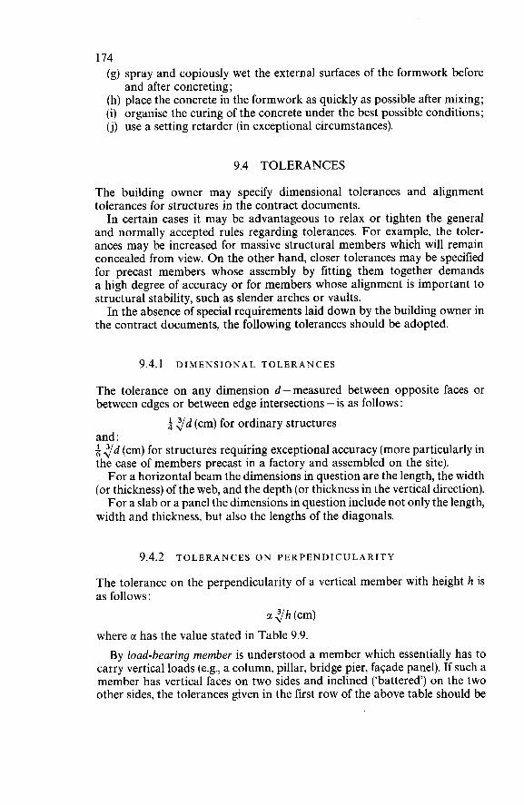
174 (g) spray and copiously wet the external surfaces of the formwork before
(h) place the concrete in the formwork as quickly as possible after mixing; (i) organise the curing of the concrete under the best possible conditions; (j) use a setting retarder (in exceptional circumstances).
and after concreting;
9.4 TOLERANCES
The building owner may specify dimensional tolerances and alignment tolerances for structures in the contract documents. In certain cases it may be advantageous to relax or tighten the general
and normally accepted rules regarding tolerances. For example, the toler- ances may be increased for massive structural members which will remain concealed from view. On the other hand, closer tolerances may be specified for precast members whose assembly by fitting them together demands a high degree of accuracy or for members whose alignment is important to structural stability, such as slender arches or vaults. In the absence of special requirements laid down by the building owner in
the contract documents, the following tolerances should be adopted.
9.4.1 DIMENSIONAL TOLERANCES
The tolerance on any dimension d-measured between opposite faces or between edges or between edge intersections -is as follows:
and : 5 y d (cm) for structures requiring exceptional accuracy (more particularly in the case of members precast in a factory and assembled on the site). For a horizontal beam the dimensions in question are the length, the width
(or thickness) of the web, and the depth (or thickness in the vertical direction). For a slab or a panel the dimensions in question include not only the length,
width and thickness, but also the lengths of the diagonals.
yd (cm) for ordinary structures
9.4.2 TOLERANCES ON PERPENDICULARITY
The tolerance on the perpendicularity of a vertical member with height h is as follows:
M l h (cm) where ci has the value stated in Table 9.9. By load-bearing member is understood a member which essentially has to
carry vertical loads (e.g., a column, pillar, bridge pier, façade panel). If such a member has vertical faces on two sides and inclined (‘battered’) on the two other sides, the tolerances given in the first row of the above table should be
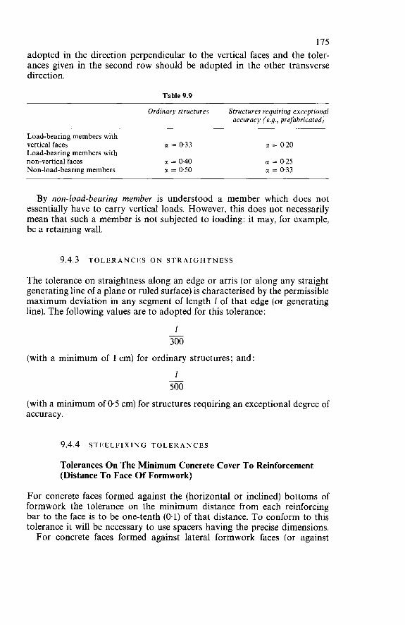
175 adopted in the direction perpendicular to the vertical faces and the toler- ances given in the second row should be adopted in the other transverse direction.
Table 9.9
Ordinary structures Structures requiring exceptional accuracy (e.g., prefabricated)
Load-bearing members with vertical faces c( = 0.33 Load-bearing members with non-vertical faces c( = 040 Non-load-bearing members m = 0.50
m = 0.20 u = 0.25 m = 0.33
By non-load-bearing member is understood a member which does not essentially have to carry vertical loads. However, this does not necessarily mean that such a member is not subjected to loading: it may, for example, be a retaining wall.
9.4.3 TOLERANCES O N STRAIGHTNESS
The tolerance on straightness along an edge or arris (or along any straight generating line of a plane or ruled surface) is characterised by the permissible maximum deviation in any segment of length 1 of that edge (or generating line). The following values are to adopted for this tolerance:
1 300 -
(with a minimum of 1 cm) for ordinary structures; and:
1 500
(with a minimum of 0.5 cm) for structures requiring an exceptional degree of accuracy.
-
9.4.4 STEEL FIXING TOLE R A N C E S
Tolerances O n The Minimum Concrete Cover To Reinforcement (Distance T o Face Of Formwork)
For concrete faces formed against the (horizontal or inclined) bottoms of formwork the tolerance on the minimum distance from each reinforcing bar to the face is to be one-tenth (0.1) of that distance. To conform to this tolerance it will be necessary to use spacers having the precise dimensions. For concrete faces formed against lateral formwork faces (or against
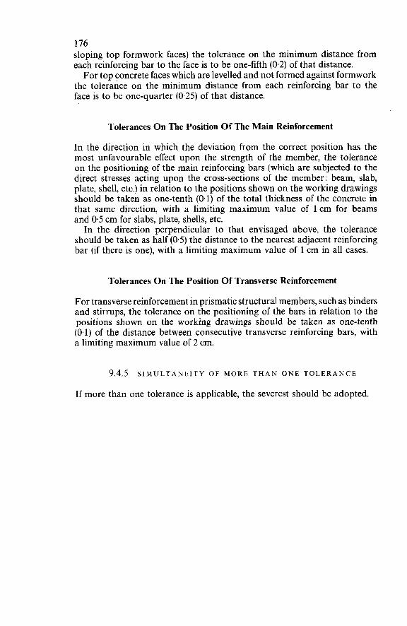
176 sloping top formwork faces) the tolerance on the minimum distance from each reinforcing bar to the face is to be one-fifth (0.2) of that distance. For top concrete faces which are levelled and not formed against formwork
the tolerance on the minimum distance from each reinforcing bar to the face is to be one-quarter (0.25) of that distance.
Tolerances O n The Position O f The Main Reinforcement
In the direction in which the deviation from the correct position has the most unfavourable effect upon the strength of the member, the tolerance on the positioning of the main reinforcing bars (which are subjected to the direct stresses acting upon the cross-sections of the member: beam, slab, plate, shell, etc.) in relation to the positions shown on the working drawings should be taken as one-tenth (0.1) of the total thickness of the concrete in that same direction, with a limiting maximum value of 1 cm for beams and 0.5 cm for slabs, plate, shells, etc. In the direction perpendicular to that envisaged above, the tolerance
should be taken as half (0.5) the distance to the nearest adjacent reinforcing bar (if there is one), with a limiting maximum value of 1 cm in ail cases.
Tolerances O n The Position O f Transverse Reinforcement
For transverse reinforcement in prismatic structural members, such as binders and stirrups, the tolerance on the positioning of the bars in relation to the positions shown on the working drawings should be taken as one-tenth (0.1) of the distance between consecutive transverse reinforcing bars, with a limiting maximum value of 2 cm.
9.4.5 SIMULTANEITY O F MORE T H A N ONE TOLERANCE
If more than one tolerance is applicable, the severest should be adopted.

Part 2
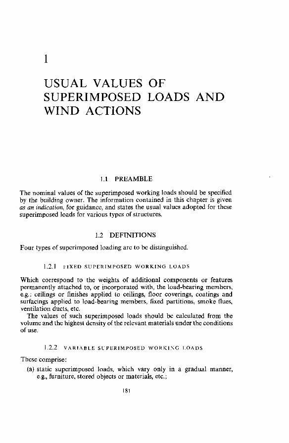
1
USUAL VALUES OF SUPERIMPOSED LOADS AND WIND ACTIONS
1.1 PREAMBLE
The nominal values of the superimposed working loads should be specified by the building owner. The information contained in this chapter is given as an indication, for guidance, and states the usual values adopted for these superimposed loads for various types of structures.
1.2 DEFINITIONS
Four types of superimposed loading are to be distinguished.
1.2.1 FIXED SUPERIMPOSED W O R K I N G LOADS
Which correspond to the weights of additional components or features permanently attached to, or incorporated with, the load-bearing members, e.g. : ceilings or finishes applied to ceilings, floor coverings, coatings and surfacings applied to load-bearing members, fixed partitions, smoke flues, ventilation ducts, etc. The values of such superimposed loads should be calculated from the
volume and the highest density of the relevant materials under the conditions of use.
1.2.2 VARIABLE SUPERIMPOSED W O R K I N G LOADS
These comprise : (a) static superimposed loads, which vary only in a gradual manner,
e.g., furniture, stored objects or materials, etc.;
182 (b) superimposed loads due to persons occupying or moving about in
T o simplify the design calculations, these superimposed loads are assumed to be uniformly distributed. Their usual values are given in Section 1.3. They include the ‘dynamic coefficient’ (see Section 1.2.3) for taking account of moving loads due to persons walking about.
the rooms of the building.
1.2.3 DYNAMIC SUPERIMPOSED WORKING LOADS
These are superimposed loads which produce a dynamic effect in the struc- ture in consequence of movements and variation of the forces involved: persons, machinery, mobile equipment such as overhead travelling cranes, etc. They are introduced into the calculations with their nominal values
multiplied by an amplification coefficient of 1.20 or 1.30 (see Section 4.2.2 of Part 1) and furthermore by a dynamic coefficient as defined in Section 4.2.3 of Part 1.
If the dynamic effect causes vibrations in the structure, the dynamic superimposed load should be considered both with the positive and with the negative algebraic sign. These two possibilities should be taken into account in the calculations.
In many cases the vibrations are long sustained or are frequently repeated, whereby fatigue effects may arise which should be taken into account.
It is furthermore advisable to compare the fundamental vibration fre- quencies and the harmonics of the structure and of its components with the frequencies of the oscillating loads in order to obviate dangerous resonance phenomena.
1.2.4 CLIMATIC SUPERIMPOSED LOADS
These are due to the effects of wind, snow and earthquake actions. Loads due to wind are dealt with in Section 1.4 of this chapter. Earthquake loads should be the subject of special investigation.
1.3 VARIABLE SUPERIMPOSED WORKING L O A D S
1.3.1 SPHERE OF APPLICATION
The values for variable superimposed working loads as indicated in Section 1.3.2, are applicable to the design of ordinary residential buildings, schools, industrial buildings, office buildings or farm buildings, but not to civil engineering structures, exhibition halls, railway stations, etc.
It is recommended that the following values. in which the dynamic co- efficient is included, should be adopted in the calculations.
183 1.3.2 NOMINAL V A L U E S FOR SUPERIMPOSED LOADS
Flat roofs
(a) Flat roofs not accessible except for maintenance (b) Privately accessible flat roofs (c) Flat roofs accessible to the public
kg/m2 100 175 500
Instead of these superimposed loads, the climatic superimposed loads or the water load up to overflow level should be taken into ac- count if any of these loads is of greater magnitude.
Dwellings
(a) Rooms (b) Stairs (c) Balconies
Offices
(a) Private rooms (except for storage of office records) (b) Public rooms (except for storage of office records) (c) Stairs
Hospitals
(a) Individual wards and treatment rooms (b) Stairs (c) Balconies (d) Multi-bed wards
Schools
(a) Classrooms (b) Stairs, ambulatories
Shops And Stores
(a) Shops (b) Department stores
175 250 350
200 250 400
175 400 350 3 50
350 400
400 500
\
184 subject to the condition that special requirements may have to be fulfilled in the case of particularly heavy goods
Theatres And Public Entertainment Buildings
Dance Halls
kg/m2 500
500
Warehouses And Workshops
The user should determine the actual superimposed loading upon the various structural members, having regard to the materials stored, the method of storage and the machines to be installed and taking due account of the coefficients justified by experience.
Garages, Passages Or Courtyards Accessible T o Vehicles
The superimposed loads to be adopted should be laid down in the special specifications, which should state the maximum load per axle, the wheel- base and minimum distance between axles, and the minimum space (on plan) occupied by a vehicle. The secondary floor members should be checked for a concentrated load
equal to the heaviest axle load applied to an area of 10 c m x 10 cm = 100 cmz (axle supported by a jack), without taking the dynamic coefficient into account. With regard to the design of columns and main beams the specifications
may take account of the loading due to the average axle load and spacing of the various types of vehicle that are likely to be parked on one and the same floor. If a garage must be designed to accommodate a particular type of commercial vehicle, this should be stated in the specifications. Unless otherwise specified, avalue of 1.15 should be adopted for the dynamic
coefficient.
1.3.3 RULES RELATING PARTICULARLY TO V A R I A B L E SUPERIMPOSED LOADS
Progressive Reduction Of Superimposed Loads In Multi-Storey Buildings
In a case where points of support carry the loads of several floors on which the maximum superimposed loads are unlikely to be acting simultaneously (residential buildings, office buildings, etc.), appropriately reduced values -
185 as defined below -can permissibly be adopted in the design calculations for the load-bearing members: Let So be the superimposed load upon the roof and let SI, S2, S, . . . S,,
be the respective superimposed loads upon the floors numbered 1, 2, 3 . . . n, starting from the top of the building. For the design of the points of support (columns, etc.) the following
superimposed loads should then be adopted: supports under roof So supports under top
supports under floor 2 supports under floor 3 supports under floor 4
floor (floor 1) SO+S, So +0.95(S1 + S,) So + 090(S, + S, + S,) So + 0.85(S1 + S2 + S, + S,)
.................................. 3 + n 2n supports under floor n
the coefficient (3 + n)/2n is valid for n > 5. If the superimposed load is the same for all the floors of the building,
the above rule of progressive reduction is equivalent to the usual rule whereby the superimposed loads for the successive floors are reduced in the following proportions:
So +--(SI.. .) (SI + S, + S3 + . . .Sn)
for the roof SO for the top floor S for the floor directly below for the next floor below this
0.90s 0.80s
and so on, applying a reduction of 10% per floor until a value of 050s is reached, which is thereafter retained for all the following floors below. In residential buildings the reduction of the superimposed loads should
not be applied to any shop or office floors that may be present; for these the full superimposed load should be adopted for designing the points of support. In principle, no reduction of the superimposed loads is allowed for the
floors of warehouses, shops, schools or workshops.
Lightweight Demountable Partitions
To take account of the possibilities of altering the positions of lightweight demountable partitions weighing approximately 300 kg/m, their effect upon the joists should - on the assumption that the partitions are normally distributed and not installed particularly close together* -be allowed for by adding 75 kg/m2 to the uniformly. distributed static superimposed load, provided that it is justified by calculation and, if necessary, by experimental means that the transverse interconnection of the joists enables the weight
*E.g. shower-bath and dressing cubicles.
186 of the partition to be distributed over a number of them and that no deforma- tions liable to cause cracking of division walls and partitions will occur.
Roofs
If the total climatic superimposed load on the members of the supporting framework (purlin, rafter) is less than 200 kg, such members should be de- signed for a concentrated superimposed load of 100 kg applied at any point, in order to take account of the weight of persons walking about on the roof, in addition to the permanent load (dead weight) of the roof covering. For the same reason the secondary roof components, such as laths,
boarding, etc. should be able to carry a uniformly distributed loading of 100 kg/m2. The actual roof covering units (other than of the traditional kind), such
as concrete slabs of more than 1 m span between supports, etc., should satisfy the same requirement. However, this requirement does not apply to brittle roof covering materials
such as slate, glass, or asbestos cement, on condition that special precautions are taken to protect these in the event of persons having access to the roof.
Mobile Equipment
The superimposed loads due to mobile equipment (overhead travelling cranes, other cranes, lifts) -i.e., ‘live loads’ in the true sense -should include the weight of such equipment, together with the reactions due to the move- ment thereof (inertial forces, impact effects, transverse forces, swaying, etc.). The building owner, in consultation with the manufacturers of the equip- ment concerned, should state these loads accurately in the special speci- fications, which should also indicate the appropriate coefficients to be applied in order to take account of dynamic effects.
Horizontal Forces On Parapets
Balcony parapets, railings, handrails and their fixings should be designed to withstand a horizontal force applied at the top, this force being 60 kg/m for private premises and 100 kg/m for those accessible to the public. The static and elastic stability should be checked for this force multiplied
by an amplification coefficient equal to 513.
Test Loads
If structural members have to be subjected to loading tests and if the en- visaged test loads are larger than the superimposed working loads, taking into account the amplification coefficients for dynamic effect in terms of its
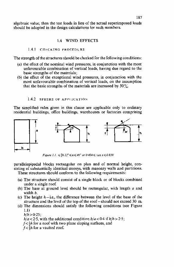
187 algebraic value, then the test loads in lieu of the actual superimposed loads should be adopted in the design calculations for such members.
1.4 WIND EFFECTS
1.4.1 CHECKING PROCEDURE
The strength of the structures should be checked for the following conditions: (a) the effect of the nominal wind pressures, in conjunction with the most
unfavourable combination of vertical loads, having due regard to the basic strengths of the materials;
(b) the effect of the exceptional wind pressures, in conjunction with the most unfavourable combination of vertical loads, on the assumption that the basic strengths of the materials are increased by 50 %.
1.4.2 SPHERE OF APPLICATION
The simplified rules given in this clause are applicable only to ordinary residential buildings, office buildings, warehouses or factories comprising
Figure 1.1. Qfh22"<u<40° or 0.404Q tanuG0.839
parallelepipedal blocks rectangular on plan and of normal height, con- sisting of substantially identical storeys, with masonry walls and partitions. These structures should conform to the following requirements:
(a) The structure should consist of a single block or of blocks combined under a single roof.
(b) The base at ground level should be rectangular, with length a and width b.
(c) The height h-i.e., the difference between the level of the base of the structure and the level of the top of the roof - should not exceed 30 m.
(d) The dimensions should satisfy the following conditions (see Figure 1.1) h/b>0.25; h/a < 2.5, with the additional condition blu < 0.4 if h(b > 2.5; f<;h for a roof with two plane sloping surfaces, and f<+h for a vaulted roof.
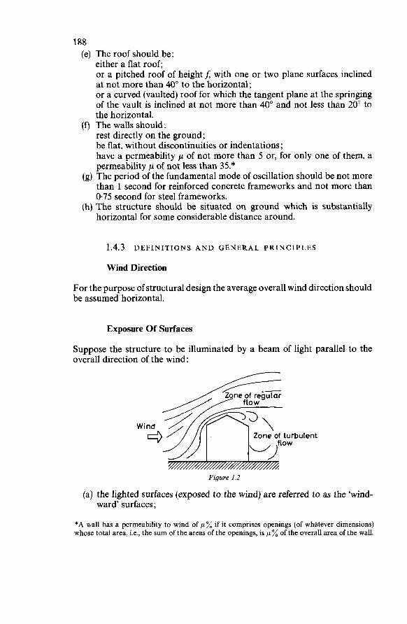
188 (e) The roof should be:
either a flat roof; or a pitched roof of height f; with one or two plane surfaces inclined at not more than 40" to the horizontal; or a curved (vaulted) roof for which the tangent plane at the springing of the vault is inclined at not more than 40" and not less than 20" to the horizontal.
(f) The walls should: rest directly on the ground; be flat, without discontinuities or indentations; have a permeability p of not more than 5 or, for only one of them, a permeability p of not less than 35.*
(g) The period of the fundamental mode of oscillation should be not more than 1 second for reinforced concrete frameworks and not more than 0.75 second for steel frameworks.
(h) The structure should be situated on ground which is substantially horizontal for some considerable distance around.
1.4.3 DEFINITIONS AND GENERAL PRINCIPLES
Wind Direction
For the purpose of structural design the average overall wind direction should be assumed horizontal.
Exposure O f Surfaces
Suppose the structure to be illuminated by a beam of light parallel to the overall direction of the wind:
Figure 1.2
'bulent
(a) the lighted surfaces (exposed to the wind) are referred to as the 'wind- ward' surfaces;
*A wail has a permeability to wind of p% if it comprises openings (of whatever dimensions) whose total area, i.e., the sum of the areas of the openings, is p % of the overall area of the wall.
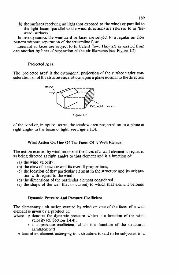
189 (b) the surfaces receiving no light (not exposed to the wind) or parallel to
the light beam (parallel to the wind direction) are referred to as ‘lee- ward’ surfaces.
In aerodynamics the windward surfaces are subject to a regular air flow
Leeward surfaces are subject to turbulent flow. They are separated from pattern without separation of the streamline flow.
one another by lines of separation of the air filaments (see Figure 1.2).
Projected Area
The ‘projected area’ is the orthogonal projection of the surface under con- sideration, or of the structure as a whole, upon a plane normal to the direction
Figure 1.3
of the wind or, in optical terms, the shadow area projected on to a plane at right angles to the beam of light (see Figure 1.3).
Wind Action On One Of The Faces Of A Wall Element
The action exerted by wind on one of the faces of a wall element is regarded as being directed at right angles to that element and is a function of: (a) the wind velocity; (b) the class of structure and its overall proportions; (c) the location of that particular element in the structure and its orienta-
(d) the dimensions of the particular element considered; (e) the shape of the wall (flat or curved) to which that element belongs.
tion with regard to the wind;
Dynamic Pressure And Pressure Coefficient
The elementary unit action exerted by wind on one of the faces of a wall element is given by a product cq, where: q denotes the dynamic pressure, which is a function of the wind
c is a pressure coefficient, which is a function of the structural
A face of an element belonging to a structure is said to be subjected to a
velocity (cf. Section 1.4.4);
arrangements.
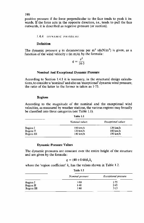
190 positive pressure if the force perpendicular to the face tends to push it in- wards. If the force acts in the opposite direction, i.e., tends to pull the face outwards, it is described as negative pressure (or suction).
1.4.4 DYNAMIC PRESSURE
Definition
The dynamic pressure q in decanewtons per m2 (daN/m2) is given, as a function of the wind velocity v (in m/s), by the formula:
V Z q = - 16.3
Nominal And Exceptional Dynamic Pressure
According to Section 1.4.1 it is necessary, in the structural design calcula- tions, to consider a ‘nominal’ and also an ‘exceptional’ dynamic wind pressure; the ratio of the latter to the former is taken as 1.75.
Regions
According to the magnitude of the nominal and the exceptional wind velocities, as measured by weather stations, the various regions may broadly be classified into three categories (see Table 1.1).
Table 1.1
Nominal values Exceptional values
Region I Region II Region III
100 km/h 120 km/h 140 km/h
130 km/h 160 km/h 190 km/h
Dynamic Pressure Values
The dynamic pressures are constant over the entire height of the structure and are given by the formula:
q = (48 + O.6h)krk, where the ‘region coefficient’ k, has the values shown in Table 1.2.
Table 1.2
Nominal pressure Exceptional pressure
Region I 1.00 1.75 Region II 1.40 245 Region III 1.80 3.15
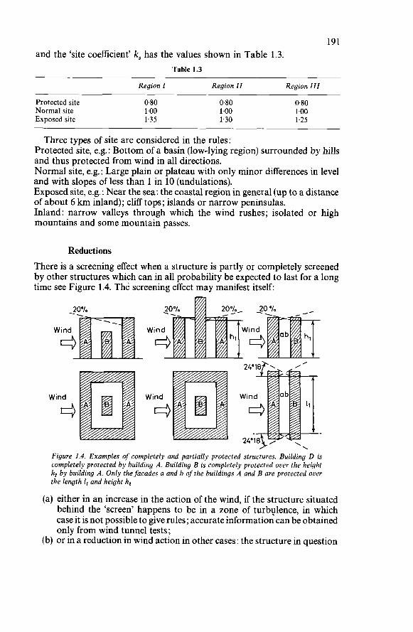
191 and the ‘site coefficient’ k, has the values shown in Table 1.3.
Table 1.3
Region I Region II Region 111
Protected site Normal site Exposed site
0.80 1.00 1.35
0.80 1.00 1.30
0.80 1.00 1.25
Three types of site are considered in the rules: Protected site, e.g.: Bottom of a basin (low-lying region) surrounded by hills and thus protected from wind in all directions. Normal site, e.g. : Large plain or plateau with only minor differences in level and with slopes of less than 1 in 10 (undulations). Exposed site, e.g.: Near the sea: the coastal region in general (up to a distance of about 6 km inland); cliff tops; islands or narrow peninsulas. Inland: narrow valleys through which the wind rushes; isolated or high mountains and some mountain passes.
Reductions There is a screening effect when a structure is partly or completely screened by other structures which can in all probability be expected to last for a long time see Figure 1.4. The screening effect may manifest itself:
Figure 1.4. Examples of completely and partially protected structures. Building D is completely protected by building A. Building B is completely protected over the height h, by building A. Only the facades a and b of the buildings A and B are protected over the length 1, and height h,
(a) either in an increase in the action of the wind, if the structure situated behind the ‘screen’ happens to be in a zone of turbulence, in which case it is not possible to give rules; accurate information can be obtained only from wind tunnel tests;
(b) or in a reduction in wind action in other cases: the structure in question
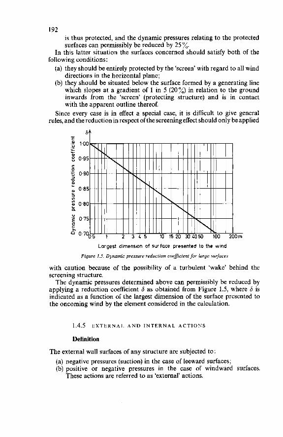
192 is thus protected, and the dynamic pressures relating to the protected surfaces can permissibly be reduced by 25 %.
In this latter situation the surfaces concerned should satisfy both of the
(a) they should be entirely protected by the ‘screen’ with regard to all wind directions in the horizontal piane;
(b) they should be situated below the surface formed by a generating line which slopes at a gradient of 1 in 5 (20%) in relation to the ground inwards from the ‘screen’ (protecting structure) and is in contact with the apparent outline thereof.
Since every case is in effect a special case, it is difficult to give general rules, and the reduction in respect of the screening effect should only be applied
following conditions :
Largest dimension of surface presented to the wind Figure 1.5. Dynamic pressure reduction coeficient for large surfaces
with caution because of the possibility of a turbulent ‘wake’ behind the screening structure. The dynamic pressures determined above can permissibly be reduced by
applying a reduction coefficient 6 as obtained from Figure 1.5, where 6 is indicated as a function of the largest dimension of the surface presented to the oncoming wind by the element considered in the calculation.
1.4.5 EXTERNAL A N D INTERNAL ACTIONS
Definition
The external wall surfaces of any structure are subjected to : (a) negative pressures (suction) in the case of leeward surfaces; (b) positive or negative pressures in the case of windward surfaces.
These actions are referred to as ‘external’ actions.
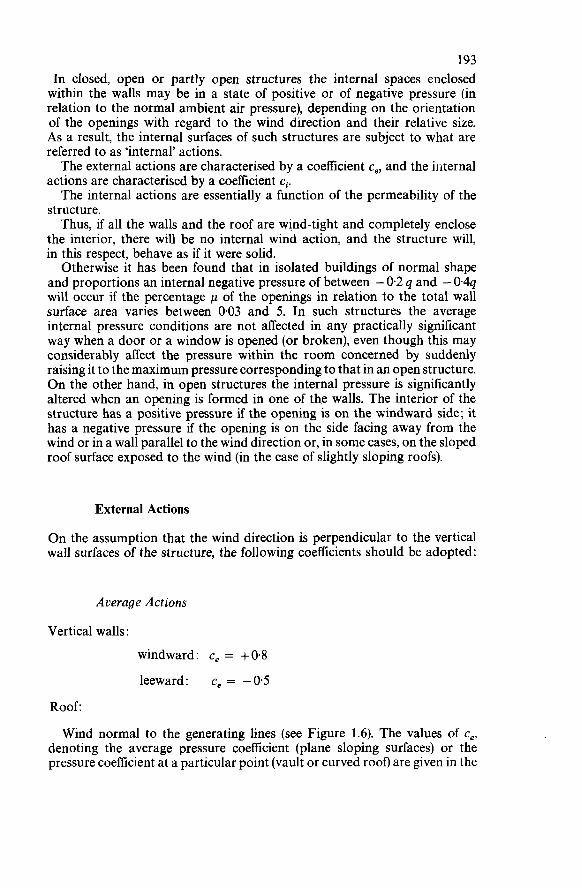
193 In closed, open or partly open structures the internal spaces enclosed within the walls may be in a state of positive or of negative pressure (in relation to the normal ambient air pressure), depending on the orientation of the openings with regard to the wind direction and their relative size. As a result, the internal surfaces of such structures are subject to what are referred to as 'internal' actions. The external actions are characterised by a coefficient ce, and the internal
actions are characterised by a coefficient ci. The internal actions are essentially a function of the permeability of the
structure. Thus, if all the walls and the roof are wind-tight and completely enclose
the interior, there will be no internal wind action, and the structure will, in this respect, behave as if it were solid.
Otherwise it has been found that in isolated buildings of normal shape and proportions an internal negative pressure of between - 0.2 q and - 0.4q will occur if the percentage p of the openings in relation to the total wall surface area varies between 0.03 and 5. In such structures the average internal pressure conditions are not affected in any practically significant way when a door or a window is opened (or broken), even though this may considerably affect the pressure within the room concerned by suddenly raising it to the maximum pressure corresponding to that in an open structure. O n the other hand, in open structures the internal pressure is significantly altered when an opening is formed in one of the walls. The interior of the structure has a positive pressure if the opening is on the windward side; it has a negative pressure if the opening is on the side facing away from the wind or in a wall parallel to the wind direction or, in some cases, on the sloped roof surface exposed to the wind (in the case of slightly sloping roofs).
External Actions
O n the assumption that the wind direction is perpendicular to the vertical wall surfaces of the structure, the following coefficients should be adopted:
Average Actions
Vertical walls :
windward: ce = +O8 leeward: ce = -05
Roof:
Wind normal to the generating lines (see Figure 1.6). The values of e,, denoting the average pressure coefficient (plane sloping surfaces) or the pressure coefficient at a particular point (vault or curved roof) are given in the
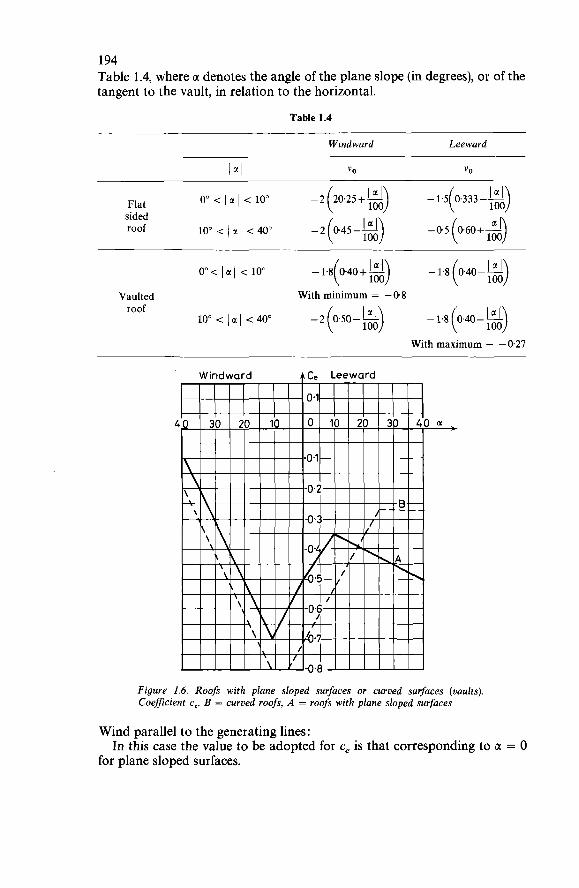
194 Table 1.4, where u denotes the angle of the plane slope (in degrees), or of the tangent to the vault, in relation to the horizontal.
Table 1.4
Windward Leeward
IaI YO "O
Flat o" < la1 < 10" -2 (20.25 +gj sided roof lO"<IaI <4o"
o"< la( < 10" - 1 - 8 ( 0 4 0 + ~ j -1.8(04I-$j
Vaulted With minimum = -0.8 roof
10" < IC(( < 40" -2k50-i) - 1.8 0.40- - ( !;A) With maximum = -0.27
4
Figure 1.6. Roofs with plane sloped surfaces or curved surfaces (vaults). Coefficient ce. B = curved roofs, A = roofs with plane sloped surfaces
Wind parallel to the generating lines:
for plane sloped surfaces. In this case the value to be adopted for ce is that corresponding to u = O
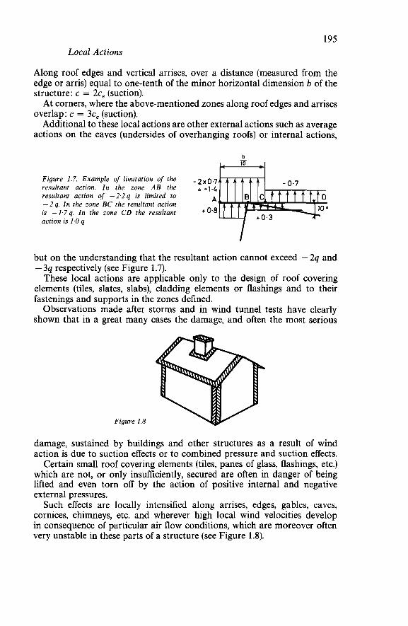
195 Local Actions
Along roof edges and vertical arrises, over a distance (measured from the edge or arris) equal to one-tenth of the minor horizontal dimension b of the structure: c = 2c, (suction). At corners, where the above-mentioned zones along roof edges and arrises
overlap: c = 3c, (suction). Additional to these local actions are other external actions such as average
actions on the eaves (undersides of overhanging roofs) or internal actions,
b - Figure 1.7. Example of limitation of the -2,.0,7 resultant action. In the zone AB the = -i.&
A resultant action of -2.2q is limited to -2 q. In the zone BC the resultant action is - 1.7 q. In the zone CD the resultant action is 1.0 q
+
but on the understanding that the resultant action cannot exceed -2q and - 3q respectively (see Figure 1.7). These local actions are applicable only to the design of roof covering
elements (tiles, slates, slabs), cladding elements or flashings and to their fastenings and supports in the zones defined. Observations made after storms and in wind tunnel tests have clearly
shown that in a great many cases the damage, and often the most serious
Figure 1.8
damage, sustained by buildings and other structures as a result of wind action is due to suction effects or to combined pressure and suction effects. Certain small roof covering elements (tiles, panes of glass, flashings, etc.)
which are not, or only insufficiently, secured are often in danger of being lifted and even torn off by the action of positive internal and negative external pressures. Such effects are locally intensified along arrises, edges, gables, eaves,
cornices, chimneys, etc. and wherever high local wind velocities develop in consequence of particular air flow conditions, which are moreover often very unstable in these parts of a structure (see Figure 1.8).
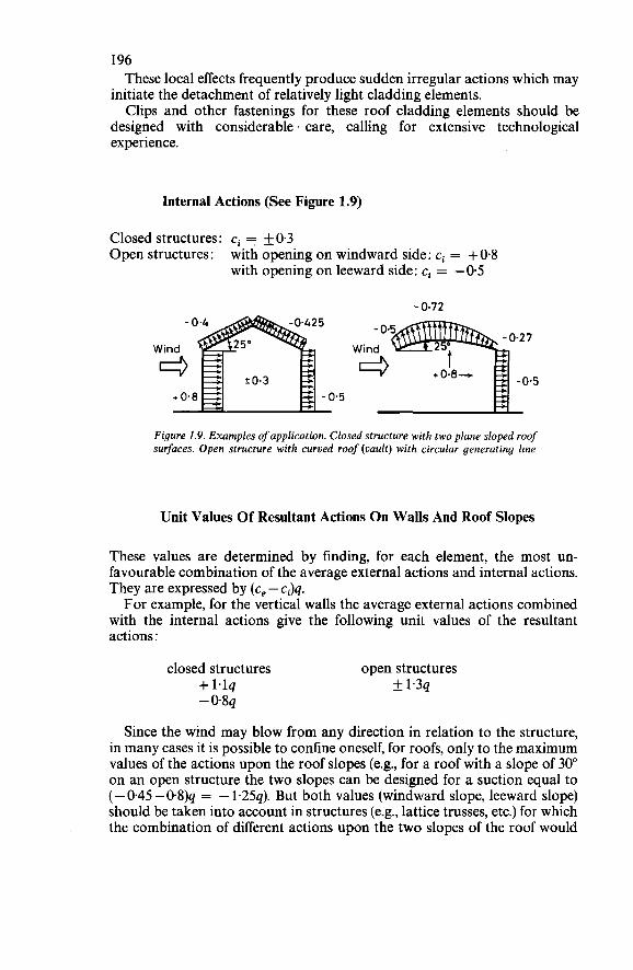
196 These local effects frequently produce sudden irregular actions which may
initiate the detachment of relatively light cladding elements. Clips and other fastenings for these roof cladding elements should be
designed with considerable care, calling for extensive technological experience.
Internal Actions (See Figure 1.9)
Closed structures: ci = f0.3 Open structures: with opening on windward side: ci = + O 4
with opening on leeward side: ci = -0.5
- 0.72
Figure 1.9. Examples of application. Closed structure with two plane sloped roof surfaces. Open structure with curved roof (vault) with circular generating line
Unit Values Of Resultant Actions O n Walls And Roof Slopes
These values are determined by finding, for each element, the most un- favourable combination of the average external actions and internal actions. They are expressed by (ce - ci)q. For example, for the vertical walls the average external actions combined
with the internal actions give the following unit values of the resultant actions :
closed structures open structures + 1.lq f 1.3q - 0.8q
Since the wind may blow from any direction in relation to the structure, in many cases it is possible to confine oneself, for roofs, only to the maximum values of the actions upon the roof slopes (e.g., for a roof with a slope of 30" on an open structure the two slopes can be designed for a suction equal to (- 0.45 - 0.8)q = - 1.25q). But both values (windward slope, leeward slope) should be taken into account in structures (e.g., lattice trusses, etc.) for which the combination of different actions upon the two slopes of the roof would
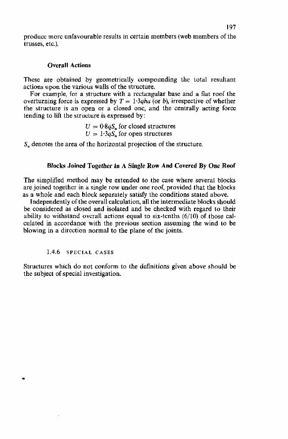
197 produce more unfavourable results in certain members (web members of the trusses, etc.).
Overall Actions
These are obtained by geometrically compounding the total resultant actions upon the various walls of the structure. For example, for a structure with a rectangular base and a flat roof the
overturning force is expressed by T = 1.3qha (or b), irrespective of whether the structure is an open or a closed one, and the centrally acting force tending to lift the structure is expressed by:
U 5 O&& for closed structures U 5 1.3qSU for open structures
S, denotes the area of the horizontal projection of the structure.
Blocks Joined Together In A Single Row And Covered By One Roof
The simplified method may be extended to the case where several blocks are joined together in a single row under one roof, provided that the blocks as a whole and each block separately satisfy the conditions stated above.
Independently of the overall calculation, all the intermediate blocks should be considered as closed and isolated and be checked with regard to their ability to withstand overall actions equal to six-tenths (6/10) of those cal- culated in accordance with the previous section assuming the wind to be blowing in a direction normal to the plane of the joints.
1.4.6 SPECIAL CASES
Structures which do not conform to the definitions given above should be the subject of special investigation.
e
2
DETERMINATION OF SAFETY ON THE BASIS OF PROBABILITY
2.1 PRELIMINARY CONSIDERATIONS
When a structure collapses or, in more general terms, becomes unfit for ser- vice, this depends on a large number of factors that render it unsafe. These factors include: inaccuracy in knowing the values of the super-
imposed (or live) loads and other actions that the structure will have to support throughout its service life; inaccuracy in the basic hypotheses and in the design calculations; the degree of skill put into the design; inaccuracy in the design engineer’s assumptions as to the basic properties of the con- crete and steel or the failure of these materials to comply with those pro- perties; the degree of strictness with which the materials are checked and the quality of execution of the work is supervised; and the possible deterioration of the structure in course of time. Since these factors which make a structure unsafe are of a random character,
it appears rational to introduce the conception of probability in establishing methods for the determination of structural safety. Actually, the problem consists in keeping the probability of collapse, or unfitness for service, within a permissible limit which must take various factors into account, such as: cost of construction, maintenance of the structure. insurance against various risks, psychological considerations, etc., and must do this in accordance with criteria comparable to those used in assessing insurance risks. Obviously, the conventional notion of the factor of safety as an arbitrary
overall figure makes only very inaccurate allowance for all these parameters and their effects on structural safety. However, for a probability analysis to have the requisite reliability, it is
essential to know the corresponding laws of statistical distribution. Un- fortunately, the statistical data at present available are still very inadequate. Indeed, in many cases they are non-existent. Hence it appears difficult tq
I98
199 envisage so rigorous and reliable an application of the probability theory to the practical determination of structural safety. This difficulty prompted the Comité Européen du Béton and the Conseil
International du Bâtiment to develop a semi-probability method, which con- sists in defining characteristic values of the mechanical strengths and the loadings, calculated from the average values thereof by introducing the standard deviation and assuming a normal statistical distribution for the experimental results. To these characteristic values are applied a reduc- tion coefficient (for the mechanical strength properties) and an amplification coefficient (for the loadings) which may take account of the greater or less degree of uncertainty in our knowledge and in the actual functioning con- ditions of a structural member considered in the structure as a whole. T o each limit state of the structure corresponds a set of Coefficients whereby the safety appropriate to that particular state can be determined. The rules given in the UNESCO Code are based on similar principles,
but, with a view to simplifying the procedure, the following modifications have been introduced for most normal purposes of design :
(a) The characteristic value of the steel strength and concrete strength has been replaced by the guaranteed minimum value.
(b) Instead of applying an amplification coefficient to the loadings, a further reduction of the strengths is applied, with the result that the amplification and reduction coefficients are reduced to two in all, namely, a single factor of safety for each of the two materials, and that the characteristic loadings are used directly in the calculation.
2.2 THE PRINCIPLES OF THE PROBABILITY THEORIES OF SAFETY
The object of the analysis of strlictural safety is to ensure that the probability of reaching the envisaged limit state will remain below a certain value est- ablished in advance for the type of structure considered. In so far as is compatible with moral considerations (such as respect for
human life) and, possibly, with psychological considerations (e.g., possible reactions of public opinion following an accident), the permissible limiting value could be so determined as to achieve a minimum for the total of the initial cost of the structure, the capital sum needed to maintain it during its service life, and the amount of fictitious insurance premium covering the risks of material damage and personal injury during construction and throughout its service life. This fictitious premium should take account of the possibility of the structure being rendered unfit for service, this being dependent upon the probability relationships deduced from the collected statistical data. A complete probability calculation would call for a knowledge of the
pattern of distribution of the most unfavourable loadings liable to occur during the construction and throughout the service lives of similar structures, and also for a knowledge of the capacity of the structure or of its various members to resist such loadings. It would therefore be necessary to take into
200 account all the random factors that could affect the probability of reaching the envisaged limit state: (a) The degree of approximation of the actual calculation and. in particular,
of the basic assumptions, having due regard to the nature of the struc- ture, its value as a design, and its constructional features.
(b) The strength values of the materials in the most severely loaded zones, particularly with regard to the choice of the construction methods and the quality of the workmanship, the strictness of control and supervision applied, and the deterioration of the structure in the course of its service life.
(c) The values of the loadings which are most unfavourable with regard to stability.
However, the necessary statistical data are at present inadequate or en- tirely lacking. Under these conditions the systematic and general application of the probability principles presents serious difficulties. It is therefore advisable to confine oneself to making the best possible use of the statistical results already obtained and estimating as well as possible the dispersions concerning which little valid information is available at the present time. Later, corrections will have to be made as more knowledge is acquired. It should, finally, be noted that certain phenomena cannot be regarded as being entirely of a random character.
2.3 C.E.BJC.1.B. SEMI-PROBABILITY DESIGN METHOD The semi-probability concept adopted by the Comité Européen du Béton (C.E.B.) and the Conseil International du Bâtiment (C.I.B.) consists in limit- ing - as a first approximation - the actual statistical analysis to the study of the variation of the strengths and the intensity of the loads and other actions. For these quantities the dispersion (or scatter) of the data is taken into account by the introduction of characteristic values G, which are estimated by means of expressions having the following general form :
G, = Gm( 1 f k6) where G, is the mean value of the quantity considered, 6 is its relative standard deviation, and k is a variable coefficient whose value depends on the pro- bability - accepted a priori - that the data will be outside the interval
These considerations lead to the adoption of a characteristic value for the strengths (‘characteristic strengths’), which defines the mechanical properties of the materials, and a characteristic value for the permanent loads, super- imposed loads and other actions (‘characteristic loadings’). As for the remaining uncertainties, which are not amenable to statistical
analysis, these are taken into account by the application of a series of design coefficients y to the characteristic quantities. Thus, for the materials so-called ‘design strengths’ are defined, which are equal to the characteristic strengths divided by a reduction coefficient y,,, which allows for the fact that the actual mechanical properties of the steel and concrete may be inferior to those assumed in the design. Similarly, for the permanent loads, superimposed
(Gm, GJ
20 1 loads and other actions so-called ‘design loadings’ are used as the basic design values, these being equal to the characteristic loadings multiplied by an amplification coefficient y, which allows for the fact that the loadings actually applied to the structure may be higher or may give rise to effects that are more unfavourable than those assumed in the design. Under these conditions, determining the safety of a structure consists in
checking that, in all the limit states, the effects of the design loadings do not exceed the values that can permissibly be attained with reference to the design strengths of the materials. In other words, for a given loading and a given material, the overall factor of safety is equal to the product y,. y,. This semi-probability method offers many advantages. In the first place, and despite any appearance to the contrary, it is not a
complicated method, the product of abstract speculations of novelty-seeking experts. By way of example it is of interest to call attention to a. specific problem to which the semi-probability method provides a simple solution: Consider the ultimate strength of a reinforced concrete section subjected to bending. Obviously, it will be necessary to adopt a different margin of safety according as failure of the concrete or failure of the steel causes failure of the member. Since the failure of the concrete is, generally speaking, less precisely predictable than that of the steel, it stands to reason that a larger reduction coefficient should be applied to the concrete strength than to the steel strength. In this way a greater measure of safety can be obtained for sections which fail as a result of concrete failure than for those which fail as a result of steel failure. This approach to the problem is in fact precisely the approach that the semi-probability method adopts. Besides, it is a perfectly logical method, inasmuch as it assigns to each of
the uncertainty factors a share of the overall safety of the structure. The introduction of characteristic strengths and characteristic loadings takes account of the variability of the mechanical properties of the materials and the variability of the various kinds of superimposed loads, while the reduction coefficients y, for the characteristic strengths and applification coefficients y, for the characteristic loadings take the other uncertainty factors into account, such as faults of construction, the inaccuracy of the design assump- tions, errors in the interpretation of the behaviour of the structure, etc. Evidently, this procedure enables all those who share responsibility for the structure -manufacturers of the materials, designer, contractor -to form a precise idea of the safety margin available to them and thus to assess their own respective responsibilities.
2.4 CHARACTERISTIC VALUES AND DESIGN VALUES OF THE PERMANENT LOADS, SUPERIMPOSED LOADS
AND OTHER ACTIONS 2.4.1 GENERAL DEFINITION
For loadings that can be considered to be random in character the charac- teristic value Qk is defined by the relation:
Qk = QJ1+ kd)
202 where Q,, which is based on the statistical analysis of all structures of the same type and the same durability of the structure being designed, denotes the value of the most unfavourable loading which has a 50% probability of being exceeded (in the direction of abnormally high values) only once during the anticipated service life of the structure, while 6 denotes the relative standard deviation (or ‘dispersion coefficient’) of the distribution of the maximum loadings, and k is a coefficient depending on the probability - accepted a priori - of having loadings in excess of the value Qk. As an indication it can be said that the dispersions found to occur in certain
countries varied from O to 0.15 for the permanent loads (close to O for very large beams; between 0.08 and 0.10 for slabs; and of the order of 0.15 for materials whose specific gravity is not accurately known or varies with moisture conditions), from 0.10 to 0.20 for superimposed loads (around 0.10 for residential buildings and offices; of the order of 0.15 for certain industrial superimposed loads).
It should be noted that in certain cases a reduction of the loading may endanger the stability of the structure. However, special cases of this kind can relate only to the permanent loads, since, for superimposed loads, the least possible loading corresponds always to the absence of superimposed load. On the other hand, for permanent loads, obvious examples are the chimney or retaining wall whose own weight contributes to its stability. In such cases the characteristic value Qk is defined by the relation:
Q; = Qh( 1 - k6) where QL denotes the value of the most unfavourable loading which has a 50 % probability of being exceeded (in the direction of abnormally low values) only once during the anticipated service life of the structure, while 6 denotes the relative standard deviation (or ‘dispersion coefficient’) of the distribution of the minimum loadings, and k is a Coefficient depending on the probability -accepted a priori - of having loadings that fall short of the value Qk. For superimposed loads (or live loads) which cannot be considered to
present a random character the values to adopt in the design may be estab- lished a priori by a decision (standard highway loading, standard railway loading, convoys of military vehicles) or be chosen with reference to the intended use to which the structure will be put. In such cases the values thus established or chosen should be taken as the characteristic values. The design value of the permanent loads and superimposed loads is derived
from the characteristic value thereof by means of a relation of the type: Q* = Ys&
where the amplification coefficient y, enables the following to be taken into account: (a) The probability of reaching a limit state, which may be chosen as a
function of the extent of the harm resulting from a possible accident. The higher the probability of reaching a limit state, the higher should be the value of ys; at the same time, however, this probability should not be too high, otherwise the cost of the structure would become prohibitive.
203 (b) The possible increase of the permanent loads or superimposed loads
and of their effects beyond the anticipated values, not only as a result of statistical deviations (given by 6) of the permanent loads or the superimposed loads themselves, but also as a result of the inaccuracy of the design assumptions and possible inaccuracies of calculation and because certain influences are sometimes neglected. The coefficient y, should, inter alia, allow for the effect of the degree of approximation of the design method and other factors upon the behaviour of the structure to be designed.
(c) Possible errors of construction, which in turn affect the magnitude of the forces that the concrete and the reinforcement have to resist. Examples of this are afforded by incorrect positioning of the reinforce- ment, defective functioning of a hinge, an error in setting out the curve of an arch, the out-of-plumbness of a column, etc. This also happens when an increase or a decrease of loading is caused by deformation of formwork and affects the magnitude of the permanent loads, or indeed when any error occurs that is liable to alter significantly the geometrical dimensions of the components of the structure (beam spans, column heights, etc.) or their relative positions (e.g., accidental eccentricities in the point of application of a load). The additional forces arising from these errors and defects of execution on the site have not been taken into account in the statistical evaluation of the superimposed loads and therefore have to be catered for by an increase in the loadings. The designer should consider each problem with care. For example: y, should have a higher value for thin slabs, in which relative errors
in the thickness of the concrete and in the positioning of the reinforcing bars are more harmful and may have more serious consequences than in thick slabs. Similarly, if the application of a given load or superimposed load
corresponds to a low or zero stress due to taking account of positive and negative areas of the influence line (lattice member of a roof truss, for example), the given coefficient y, will not be sufficient (since y, x O = O). In this type of structure the stress should be increased in accordance with criteria which are rather difficult to lay down in a set of regulations. Of course, the coefficient y, does not take account of mistakes
in design, nor of serious defects in construction. (d) The probability of various loads or superimposed loads not occurring
simultaneously. The coefficient y, must also take account of the com- bination of the various categories of loads or superimposed loads (dead weight, working loads, wind, snow, etc.). Each of these loads or superimposed loads very rarely attains its maximum value, and the probability of their simultaneous occurrence is low. Accordingly, the value of ys is allowed to be reduced if it is applied to the whole set of loads and superimposed loads of various kinds (in some countries a reduction of as much as 30 % appears to be permissible).
(e) The possibility of redistribution of forces and moments. The value of
204 ys should likewise depend on the type of structure. This value could be lower for structures or structural members in which a redistribution of forces and bending moments is possible than for structures in which the failure of a single member may bring about total collapse or for members which are liable to fracture suddenly and without warning. As regards the actions arising from the effects of shrinkage, creep,
temperature, etc., these should also be multiplied by an amplification coefficient ys whose magnitude should be determined in accordance with the same principles.
2.4.2 CHARACTERISTIC VALUES A N D DESIGN VALUES OF THE PERMANENT LOADS
Apart from exceptional cases, no dispersion should be assumed to exist in the values of the permanent loads estimated from the volume and density of the materials in the conditions in which they are used (i.e., 6 = O). The exceptional cases include more particularly those where the stability against overturning is concerned and where the density of the materials is not accurately known or is liable to vary (6 # O). In such cases a value k = 1 may be adopted, so that the relation for the characteristic permanent loads then becomes :
G, = G,(1 f 6)
with the sign corresponding to the most unfavourable effect.
Ultimate Limit State
The design values of the permanent loads are derived from the characteristic permanent loads by the application of the amplification coefficient ys = 1.40. However, in the exceptional limiting case where all the most favourable conditions of design, construction or use of the structure are simultaneously satisfied (accuracy of the basic assumptions, exactness of the design methods and calculations, very careful design of anchorages and structural con- nections, careful workmanship, constant supervision, only material damage - not personal injury - resulting from a possible structural mishap) this amplification coefficient for the ultimate limit state may be reduced to : ys = 1.25. In fact, it is very rare for these ideal conditions to be all satisfied simultaneously. And if this is not so, the following additions to, or deductions from, the value of 1.25 should be made: +0.15 in the case of uncertain assumptions, design and calculations carried
+0.15 in the case of moderately good workmanship; +0.15 in the case of very considerable risks of damage; -0.15 in the case of very slight risks of damage.
out with moderate care;
205 Finally, on adding together these increases or reductions, the following
value for the ultimate limit state is obtained in almost every case:
y, = 1.40
Limit State Of Instability
For the limit state of instability, which generally corresponds to the case of failure without warning and is liable to bring about the total collapse of the structure, the coefficient y, relating to the member under consideration should be suitably increased with regard to the value ys = 1.40. It is advisable to adopt: y, = 1.70.
Limit States Of Cracking And Deformation For the limit state of cracking and the limit state of deformation, which correspond practically to the normal working load conditions, the co- efficient y, may, on the other hand, be reduced to: ys = 1.00.
Summ a r y
Ultimate limit state: G* = 1.40Gk = 1.40Gm( 1 6) Limit state of cracking: G* = G, = Gm(l +a) Limit state of deformation: G* = G, = Gm( 1 f 6) Limit state of instability: G* = 1.70Gk = 1.70Gm( 1 6)
2.4.3 CHARACTERISTIC VALUES A N D DESIGN VALUES OF THE SUPERIMPOSED LOADS A N D OTHER ACTIONS
The superimposed loads and other actions comprise:
(a) the fixed superimposed loads and the working loads (live loads,
(b) the superimposed loads due to climatic conditions: snow and wind; (c) the actions that may arise from the working loads, such as braking
(d) the displacements, frictional effects and resistances of supports and
(e) the effects of shrinkage, creep and temperature variations ;
variable superimposed loads);
and swaying effects, centrifugal forces, vibration phenomena ;
bearings ;
206 (f) the effects of earthquakes (if any); (g) the influence of the method of construction (if at all). The characteristic superimposed loads should be determined by means
of the expression:
Qk = QJ1+ 6) where the value of the coefficient k by which 6 is multiplied is taken as equal to 1 and the value of the dispersion coefficient 6 is laid down in the special specifications. It should also be noted that, contrary to the procedure for certain types of permanent loads, the dispersion 6 should always be added (‘plus’ sign, never the ‘minus’ sign), for if the ‘minus’ really had to be con- sidered as applicable to certain types of superimposed loads, in any case the most unfavourable effect would always correspond to a zero value of such loads. The recommendations of the Comité Européen du Béton also lay down a
15% increase for all variable superimposed loads and live loads whose effect is much more dangerous than that of the fixed superimposed loads. This increase of 15 % takes account of the variation in the direction and magnitude of the stresses; it should not be confused with the usual dynamic coefficients. In fact, if the variable superimposed loads and live loads are additionally accompanied by dynamic effects, these loads must, over and above the 15 % increase referred to just now, undergo a further increase by the application of so-called dynamic coefficients of suitably chosen value to take account of the influence of inertial forces, impact effects or vibration and their resultant phenomena. The design values of the superimposed loads are derived from the charac-
teristic superimposed loads by application of the same amplification co- efficient as to the permanent loads (see summary above). Just as for these last- mentioned loads, the ys = 1.40 relating to the ultimate limit state may, in exceptional cases, be reduced to ys = 1.25. Furthermore, special rules have been laid down for certain cases of
superposition of superimposed loads. Thus, when the effect of wind has to be superimposed upon the effect
of the permanent loads and working loads, the amplification coefficient ys is allowed to be reduced by 10% (i.e., ys = 0.90 x 1.40 = 1.26), provided that the strength of the structure under these conditions is not less than the strength appropriate to the design value of the permanent load (i.e., multiplied by ys = 1.40) and to the variable superimposed loads increased by 15 % (i.e., multiplied by ys = 1.40 x 1.15 = 1.61). But if there is no working load, as in the case of a chimney, no reduction coefficient should be applied. Similarly, when the effect of an exceptional superimposed load (such as an
earthquake) has to be added to the effect of the permanent loads, working loads and other actions, the amplification coefficient ys is allowed to be reduced to ys = 1, provided that the 15% increase of the variable super- imposed loads is retained. Furthermore, the design strengths are allowed to be multiplied by 1.15. In other words, in this exceptional case, the overall factor of safety can permissibly be reduced to 1 for the steel and to 1.50/1.15 =
207 1.30 for the concrete, provided that the combination considered really is the most unfavourable.
2.5 CHARACTERISTIC STRENGTHS AND DESIGN STRENGTHS OF STEEL AND CONCRETE
2.5.1 GENERAL DEFINITION
The characteristic strength ok of a material is obtained from a statistical analysis of test results; it is defined by the relation:
[Tk = om(l -k6) where om denotes the arithmetical mean of the test results, 6 denotes the relative standard deviation (or ‘dispersion coefficient’), and k denotes a coefficient depending on the number of test results defining om and on the probability, accepted a priori, of the test results being below the characteristic value ok. The design strength o* of a material is defined by the relation:
1 o* = - Y, Ok
where the strength reduction coefficient y m is a function of the statistical laws relating to the mistakes or shortcomings committed during construction and resulting in a reduction of the strength of the cross-sections. For the steel, for example, this may be due to inadequacy of the cross-
sectional areas of the reinforcement, which in turn may be due either to a fault in the manufacture of the bars or to a mistake in the bar-bending shop or a mistake in fixing the steel on the site. For the concrete the risks of deviations are much greater than for the
reinforcement : (a) Whereas the strength of the steel can be accurately determined by
tests on specimens, the tests performed on the concrete may not correspond to the actual strength of the concrete in the structure. This actual strength may be affected by: small accidental errors in
batching the cement or the water in a batch of concrete; by handling and transport; by climatic conditions at the time of concreting (heat, frost, rain, wind); or by inadequate compaction.
(b) The concrete cross-section may be inadequate on account of the presence of voids (gravel pockets) or a reduction in the formwork. dimensions as a result of a mistake in constructing the formwork or of an accidental deformation thereof.
(c) Short-term tests hardly ever show up the unfavourable effects of loads of very long duration.
(d) In addition, in many cases failure of the concrete may, much more frequently than failure of the steel, bring about total failure of the structure, without any warning signs.
208
practice, be 1.25 to 1.50 times as high as that for the steel. For these various reasons the value of ym for the concrete should, in
2.5.2 CHARACTERISTIC STRENGTH A N D DESIGN STRENGTH OF THE STEEL
The characteristic strength of the steel is the value corresponding to the probability that, in a normal statistical distribution of the results of tests for measuring the elastic limit, 5 % of the results wili be below the specified value. This probability of 5 % entails: k = 1.64; hence:
The design strength of the steel is derived from the characteristic strength by application of the reduction coefficient y, = 1.15 for the ultimate limit state and the limit state of instability and y, = 1.60 for the limit state of cracking and the limit state of deformation, i.e.
1.15 1.15
(ultimate limit state and limit state of instability)
.a*=-&= O O,,,,( 1 - 1.646)
1.60
(limit state of cracking and limit state of deformation)
2.5.3 CHARACTERISTIC STRENGTH A N D DESIGN STRENGTH OF THE CONCRETE
The characteristic strength of the concrete is the value corresponding to the probability that, in a normal statistical distribution of the results of tests for measuring the strength (compressive or tensile strength), 5 % of the results will be below the specified value. This probability of 5% entails: k = 1.64. However, on no account must a relative standard deviation of less than 7 % be considered; hence:
obk = Obrn( 1 - 1.646) < 0'8850b,
An approximation which yields very much the same value but which avoids having to calculate the standard deviations consists in taking for the characteristic strength twice the mean value of half the results below the median, minus the mean value of all the results. The design strength of the concrete is derived from the characteristic
strength by application of the reduction coefficient Y b = 1.50 for the ultimate
209 limit state and the limit state of instability, Y b = 1.30 for the limit state of cracking, and Y b = 1 for the limit state of deformation, i.e.:
(ultimate limit state and limit state of instability)
(limit state of cracking)
(limit state of deformation)
These values are valid for concrete made under supervision on the con- struction site. The value Y b = 1.50 applicable to the ultimate limit state is allowed to be reduced to 1.40 for closely supervised, carefully batched factory- made concrete, but it should be increased to 1.60 for concrete made with only a small amount of supervision. Besides, the design strengths should be reduced by 10% for members
of small cross-sectional size which are concreted in the vertical position without special precautions, as it has been found that the quality of the concrete is liable to vary considerably throughout the height of such members.
2.6 METHOD OF CHECKING THE SAFETY
This check should obviously be carried out in the various limit states en- visaged, in particular: the ultimate limit state (failure), the limit state of cracking, the limit state of deformation, the limit state of instability and, possibly, other limit states to be considered in each particular case. It con- sists in verifying that the effects of the design loadings do not exceed the load-carrying capacity as deduced from the design strengths of the steel and concrete. This procedure of checking the safety by means of the C.E.BJC.1.B. semi-
probability method can be symbolically expressed by :
function ofsand- YO Y b
where s k denotes the various characteristic loadings to be taken into account and R denotes the design strength of the member in the limit state, this being
210 a function of the design value of the mechanical strength of the steel and concrete.
2.7 RELATION BETWEEN THE C.E.B./C.I.B. SEMI- PROBABILITY METHOD AND THE UNESCO SIMPLIFIED
METHOD
The two essential simplifications introduced in the UNESCO method and valid for the design calculations most commonly encountered consist in : (a) replacing the characteristic strength of the steel and of the concrete by
the guaranteed minimum strength; (b) shifting the amplijìcation coeficient y, for the characteristic loadings
to the reduction coeficients for the characteristic strengths of the steel and the concrete, which thus become respectively: y,. y, and ? b . ys
For practical purposes the simplified calculation is carried out with ‘characteristic loadings’ which are not increased and with ‘characteristic strengths’ which are reduced by y,. y, and Y b . y, respectively. For the notion of ‘design strengths’ is thus substituted the notion of ‘basic strengths’ accord- ing to the relation:
design strength - characteristic strength basic strength = - Y s (Ya . Ys) Or ( Y b . Ys)
This overall reduction coefficient (y,. y,) or ( Y b . y,) is therefore comparable to a single factor of safety defined for each of the materials steel and concrete. Its values are laid down in Sections 4.3.2 and 4.3.3 of Part 1 of this Manual, according to the relations :
Ysieei = Ya . Y s
Yconcrete = Y b . Y s
The corresponding basic strengths are, respectively, equal to:
ce Ysieei
steel: Ca = ~
aó concrete: ab = ~
Yconcrete
In the most frequently encountered cases this UNESCO simplified method gives results which are close to those obtained with the C.E.B./C.I.B. semi- probability method; the margin of error is on the safe side. In relevant cases the designer should judge whether it is advantageous
to reduce this margin of error and to benefit by the additional saving that he may achieve by applying the semi-probability method systematically and in full.
3
UNIAXIAL BENDING- THEORETICAL ANALYSIS
3.1 RECAPITULATION OF THE FUNDAMENTAL DESIGN A S S U M P T I O N S
In addition to the two equations of equilibrium of the forces and moments, the following basic assumptions are applied in the analysis for the limit state of a section subjected to simple or composite uniaxial bending:
3.1.1 CONDITION OF STRAIN COMPATIBILITY
The strains of the elements of a cross-section are assumed always to be proportional to the distance of these elements to the neutral axis (the ‘Navier- Bernoulli hypothesis’ which states that plane sections remain plane). The corresponding condition constitutes the strain compatibility equation.
3.1.2 TAKING ACCOUNT O F THE CONCRETE IN COMPRESSION
The stress distribution diagram j o y the concrete in the compressive zone is assumed to be a rectangle whose width is taken as equal to the basic strength Ob of the concrete and whose depth is a function of the distance x from the neutral axis to the most compressed face of the member, namely:
$x if x < h (simple bending and composite bending)
. h if x 2 h (eccentric compression) x-4h where h denotes the effective depth of the section (see Figure 3.1).
21 1

212 However, the value of the resisting moment due to the compressive stresses
in the concrete (apart from the contribution of any compressive reinforce- ment that may be provided) is limited to the value of the moment (with regard to the reinforcing bars in tension or located near the least compressed face) of the forces acting upon the total effective section assumed to be subjected
fi: -0.75bx. ü‘b (rectangular sections
- 6 2 5 ~
--+- -I-$---L Neutral axis
Figure 3.1
to a uniform stress equal to three-quarters (0.75) of the basic strength O;, of the concrete. Finally, the maximum compressive strain of the concrete in the ultimate
limit state is conventionally taken as equal to 0.2 %.
3.1.3 TAKING THE TENSILE STEEL INTO ACCOUNT
The basic stress-strain diagram for the steel is derived from the standard stress-strain diagram by affine transformation parallel to the ascending straight portion corresponding to Hooke’s law, in the ratio :
- 0.556 - 1 Ysteei 1.80
The tensile strain of the steel in the ultimate limit state is assumed to have an upper limit value of 1 %.
3.1.4 TAKING THE COMPRESSIVE STEEL INTO ACCOUNT
The compressive strain of the steel of the compressive reinforcement in the ultimate limit state is determined on the assumption that plane sections remain plane. Hence the compressive steel stress to be introduced into the
213 strength calculation is derived from the basic compressive stress-strain diagram, which is assumed to be similar - subject to reversal of the algebraic signs - to the basic tensile stress-strain diagram. In normal cases as encoun- tered in actual practice this compressive stress can be taken as equal to the basic compressive strength O:, of the steel. For the purpose of simplifying the present treatment of the subject, the
complete theoretical analysis has been worked out only in the case of ordinary reinforcing steels having a stress-strain diagram comprising a definite yield stress range, i.e., in which the tensile stress remains constant throughout the stagr in which plastic behaviour develops (‘plastification’). Similar considerations would, however, also be applicable to cold-worked steels, provided that, in the plastification stage, due account is taken of the law of variation of tensile stress as a function of the strains in accordance with the standard stress-strain diagram for the steel (reference Figure 3.2, Part 1 or Figure 6.8, Part 1 of this Manual) or, possibly, in accordance with its actual experimentally determined stress-strain diagram, if this is known with sufficient accuracy.
3.2 ANALYSIS OF A SYMMETRICAL SECTION OF ARBITRARY SHAPE
3.2.1 DETERMINATION OF THE TYPE OF FAILURE
It is known that, depending on the percentage of reinforcement, the ultimate limit state (limit state of failure) is reached either by crushing of the concrete in compression (for high steel percentages) or by yielding of the tensile reinforcement (for normal steel percentages). These two types of failure will occur simultaneously for a limit value of the percentage of reinforcement for which it is easy to determine a corresponding limit value ofy/h. When these limit values are known, it is possible to predict the nature of
the failure.
Expression Of y/h As A Function Of The Section Properties And External Loadings
In the most general case of a section subjected to compression and bending, the general equation of equilibrium of the forces can, on the assumption that the tensile reinforcement has attained its yield stress at failure of the member, be written as follows:
- N = O;, j:b. dy-A. a,+A’. a:,
where A’. O:, denotes the contribution of the compressive reinforcement (if any).
214 The integral can be replaced by a conventional expression :
lOyb. dy = b, . y,
where b, denotes the fictitious width of a rectangular section equivalent to the section considered. We thus obtain:
Y - N + A . 0,-A’. < - h - $.b,.h (3.2)
It is merely necessary to compare this value of of y/h with the limit value of y/h in order to determine whether or not failure will occur as a result of yielding of the steel.
Expression For (y/h),,,,,
The limit value of y/h is reached when the concrete attains its ultimate com- pressive strain EO and the reinforcing steel simultaneously attains the tensile strain E, corresponding to its yield stress oe. Hence, on applying the strain compatibility equation :
(3.3)
i.e. : (3.4)
O n replacing E, and E; by their respective values E, = 2.1 x lo6 bars and EO = 0.2 %, a simple expression for (y/h)limit is obtained:
0.75 (i),,,¡, = 1 + 2.38. oe (3.5)
This expression, in which o, should be expressed in bars (kg/cm2), is valid irrespective of the geometrical shape of the section and depends only on the elastic limit of the steel.
Practical Determination Of The Type Of Failure
To determine the type of failure, it is merely necessary to compare the value of y/h obtained from equation 3.2 with the value of (y/h)limit obtained from
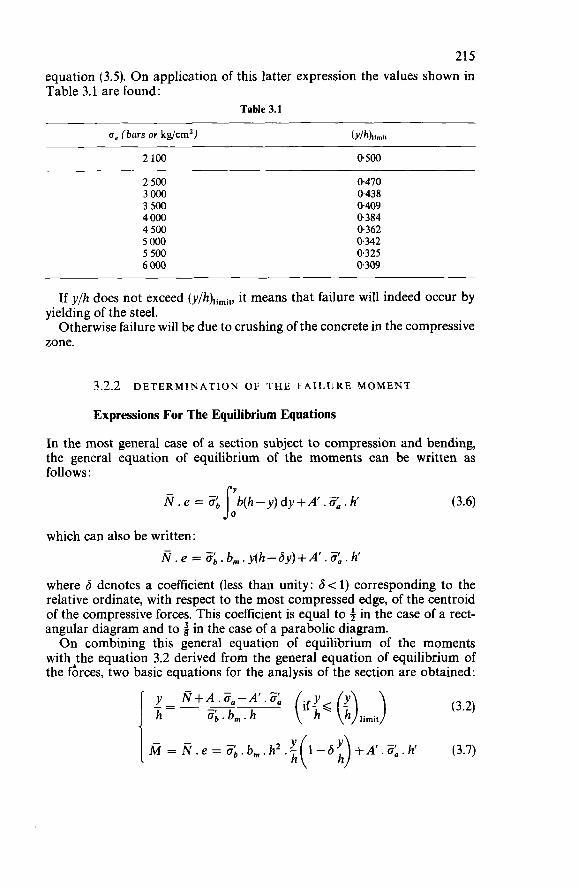
215 equation (3.5). O n application of this latter expression the values shown in Table 3.1 are found:
Table 3.1
CT, (bars or kg/cm2) (Y/hhimii
2 100 0,500
2 500 3000 3 500 4000 4 500 5 O00 5 500 6000
0.470 0,438 0.409 0,384 0.362 0.342 0.325 0.309
If y/h does not exceed (y/h),imi,, it means that failure will indeed occur by
Otherwise failure will be due to crushing of the concrete in the compressive yielding of the steel.
zone.
3.2.2 DETERMINATION OF THE FAILURE MOMENT
Expressions For The Equilibrium Equations
In the most general case of a section subject to compression and bending, the general equation of equilibrium of the moments can be written as follows :
(3.6) so - N.e = 3, b(h-y)dy+A.%.h
which can also be written: N.e = $.b,.y(h-hy)+A'.<.h'
where 6 denotes a coefficient (less than unity: 6 < 1) corresponding to the relative ordinate, with respect to the most compressed edge, of the centroid of the compressive forces. This coefficient is equal to f in the case of a rect- angular diagram and to i in the case of a parabolic diagram. O n combining this general equation of equilibrium of the moments
with the equation 3.2 derived from the general equation of equilibrium of the grces, two basic equations for the analysis of the section are obtained:
N+ A .O,- A'. 3 - o;. b, . h J := (3.2)
fi = N .e = Zb. b,. hZ .? +A'.3,. h' (3.7) I h
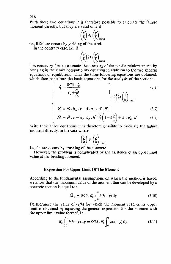
216 With these two equations it is therefore possible to calculate the failure moment directly, but they are valid only if
i.e., if failure occurs by yielding of the steel. In the contrary case, i.e., if
it is necessary first to estimate the stress on of the tensile reinforcement, by bringing in the strain compatibility equation in addition to the two general equations of equilibrium. Thus the three following equations are obtained, which then constitute the basic equations for the analysis of the section:
y - 0.75. EO h an EO +-
En I 1 (3.8)
Ñ = og.b,,,.y-A.o,+A'.Ti:,] (3.9)
M = N.e= %.b,.hZ.x h (3.7) I With these three equations it is therefore possible to calculate the failure moment directly, in the case where
(i) 2 (i)iirnii i.e., failure occurs by crushing of the concrete.
value of the bending moment. However, the problem is complicated by the existence of an upper limit
Expression For Upper Limit Of The Moment
According to the fundamental assumptions on which the method is based, we know that the maximum value of the moment that can be developed by a concrete section is equal to:
M, = 0.75 .% b(h - y) dy J: (3.10)
Furthermore the value of (y/h) for which the moment reaches its upper limit is obtained by equating the general expression for the moment with the upper limit value thereof, i.e. :
(3.11)
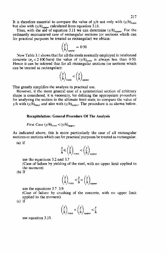
217 It is therefore essential to compare the value of y/h not only with (y/h)limit but also with (y/h),,,,, calculated from equation 3.11. Thus, with the aid of equation 3.11 we can determine (y/h)upper. For the
ordinarily encountered case of rectangular sections (or sections which can for practical purposes be treated as rectangular) we obtain :
(i)"ppe. = N o w Table 3.1 shows that for all the steels normally employed in reinforced
concrete (a, < 2 100 bars) the value of (y/h)limit is always less than 0.50. Hence it can be inferred that for all rectangular sections (or sections which can be treated as rectangular):
(i) limit < (;)upper This greatly simplifies the analysis in practical use. However, if the more general case of a symmetrical section of arbitrary
shape is considered, it is necessary, for defining the appropriate procedure for analysing the section in the ultimate limit state, to compare the value of y/h with and also with (y/h)upper. The procedure is as shown below.
Recapitulation : General Procedure Of The Analysis
First Case (Y/h)iimit < (Y/h)upper
As indicated above, this is more particularly the case of all rectangular sections or sections which can for practical purposes be treated as rectangular. (a) If
-< - 1 (i) limit < (i) upper
use the equations 3.2 and 3.1 (Case of failure by yielding of the steel, with no upper limit applied to the moment)
(b) If
use the equations 3.1-3.9. (Case of failure by crushing of the concrete, with no upper limit applied to the moment)
(4 If Y (i) iimit < (i) upper <
use equation 3.10.
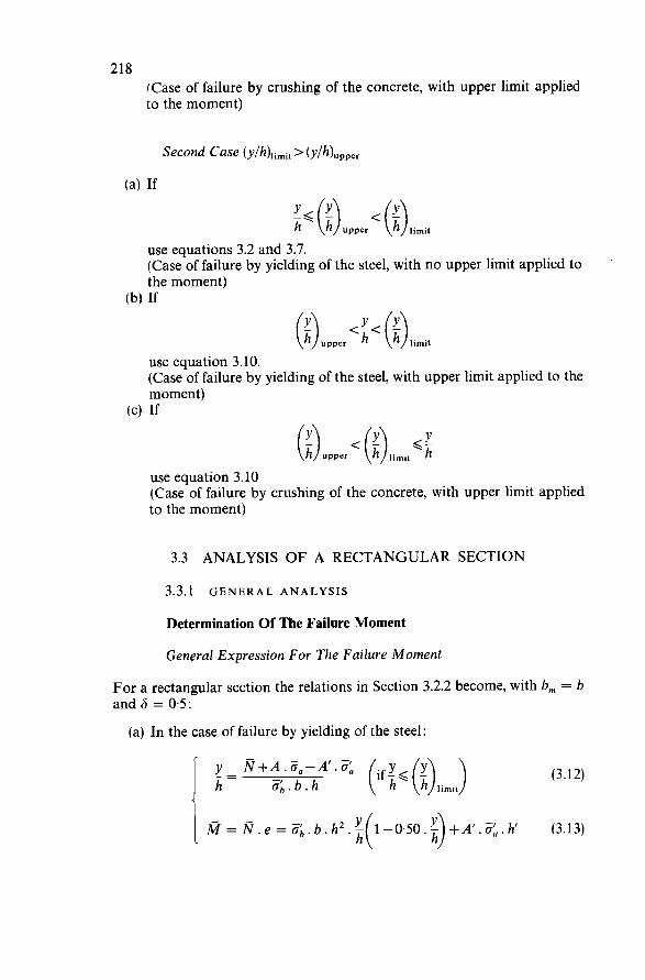
218 (Case of failure by crushing of the concrete, with upper limit applied to the moment)
use equations 3.2 and 3.7. (Case of failure by yielding of the steel, with no upper limit applied to the moment)
(b) If
use equation 3.10. (Case of failure by yielding of the steel, with upper limit applied to the moment)
(cl If
use equation 3.10 (Case of failure by crushing of the concrete, with upper limit applied to the moment)
3.3 ANALYSIS OF A RECTANGULAR SECTION
3.3.1 GENERAL ANALYSIS
Determination Of The Failure Moment
General Expression For The Failure Moment
For a rectangular section the relations in Section 3.2.2 become, with b, = b and 6 = 05:
(a) In the case of failure by yielding of the steel:
(3.12)
= N . e = &.b.hZ.x +A‘.<.h’ (3.13) I h
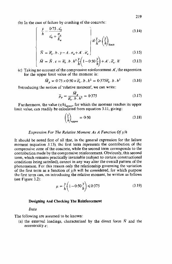
(b) In the case of failure by crushing of the concrete:
if;. (i) limii I y 0.75 .EO
oll h- EO +-
E a I 219
(3.14)
I N = Zb.b.y-A.o,+A’.3:, J (3.15)
M = N . e = Z b . b . h 2 x (3.13) h (c) Taking no account of the compressive reinforcement A’, the expression
(3.16) for the upper limit value of the moment is:
M p = 0.75 X O . ~ O X Z ~ . b. h2 = 0.3755. b. hZ Introducing the notion of ‘relative moment’, we can write:
MP - 0.375 p = - - oL.b.h2- (3.17)
Furthermore, the value (y/h)upper, for which the moment reaches its upper limit value, can readily be calculated from equation 3.11, giving:
( = (3.18)
Expression For The Relative Moment As A Function Of yfh
It should be noted first of all that, in the general expression for the failure moment (equation 3.13), the first term represents the contribution of the compressive zone of the concrete, while the second term corresponds to the contribution made by the compressive reinforcement. Obviously, this second term, which remains practically invariable (subject to certain constructional conditions being satisfied), cannot in any way alter the overall pattern of the phenomenon. For this reason only the relationship governing the variation of the first term as a function of y/h will be considered, for which purpose the first term can, on introducing the relative moment, be written as follows (see Figure 3.2):
p = - 1-0’50- G0.375 i( h) (3.19)
Designing And Checking The Reinforcement
Data
The following are assumed to be known : (a) the external loadings, characterised by the direct force and the
eccentricity e;
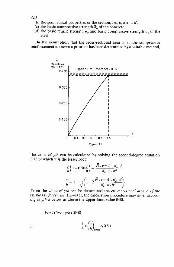
220 (b) the geometrical properties of the section, i.e., b, h and h'; (c) the basic compressive strength ob of the concrete; (d) the basic tensile strength Za and basic compressive strength 3 of the
On the assumption that the cross-sectional area A' of the compressive reinforcement is known a priori or has been determined by a suitable method,
steel.
P Reiat ive moment A
Upper limi1 moment = 0.375
0.300 -
I
O O1 0.2 0.3 04 0.5
Figure 3.2
the value of y/h can be calculated by solving the second-degree equation 3.13 of which it is the lesser root:
2 (1 -0.50;) = N . e-A'. <. h h 6 . b . h 2
Y N.e-A'.if,.h i = 1 4 1 - 2 6 . b . h 2
From the value of y/h can be determined the cross-sectional area A of the tensile reinforcement. However, the calculation procedure may differ accord- ing as y/h is below or above the upper limit value 0.50.
First Case: y/h < 0.50
If
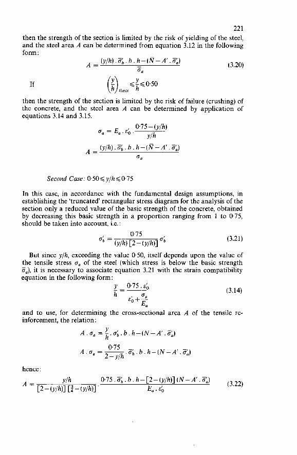
22 1 then the strength of the section is limited by the risk of yielding of the steel, and the steel area A can be determined from equation 3.12 in the following form :
If
(3.20) (y/h).&,.b.h-(N-A’.<) A = - O n
then the strength of the section is limited by the risk of failure (crushing) of the concrete, and the steel area A can be determined by application of equations 3.14 and 3.15.
0’75-(y/h) o, = E,. EO .
Y/h (y/h) .ob. b . h-(N-A’. O,)
0 0
A =
Second Case: 0.50< ylhG0.75
In this case, in accordance with the fundamental design assumptions, in establishing the ‘truncated’ rectangular stress diagram for the analysis of the section only a reduced value of the basic strength of the concrete, obtained by decreasing this basic strength in a proportion ranging from 1 to 0.75, should be taken into account, i.e. :
(3.21)
But since y/h, exceeding the value 0.50, itself depends upon the value of the tensile stress o, of the steel (which stress is below the basic strength i?,), it is necessary to associate equation 3.21 with the strain compatibility equation in the following form:
oa EO+- E a
h (3.14)
and to use, for determining the cross-sectional area A of the tensile re- inforcement, the relation :
Y h A . na = - .O;. b . h - (N - A’ . O,) 0.75 - A.0, = ~ .O; . b. h- (N - A’ . O,)
2 - Y/h
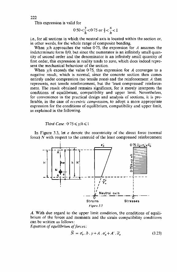
222 This expression is valid for
Y X
h h 0.50<-<0.75 or $<-< 1
i.e., for all sections in which the neutral axis is located within the section or, in other words, for the whole range of composite bending. When y/h approaches the value 0.75, the expression for A assumes the
indeterminate form O/O, but since the numerator is an infinitely small quan- tity of second order and the denominator is an infinitely small quantity of first order, this expression in reality tends to zero, which does indeed repre- sent the mechanical behaviour of the section. When y/h exceeds the value 0.75, this expression for A converges to a
negative result, which is normal, since the concrete section then comes entirely under compression (no tensile zone) and the reinforcement A then represents, not tensile reinforcement, but the ‘least compressed’ reinforce- ment. The result obtained remains significant, for it merely interprets the conditions of equilibrium, compatibility and upper limit. Nevertheless, for convenience in the practical design and analysis of sections, it is pre- ferable, in the case of eccentric compression, to adopt a more appropriate expression for the conditions of equilibrium, compatibility and upper limit, as explained in the following.
Third Case : 0.75 < y/h < 1
In Figure 3.3, let e denote the eccentricity of the direct force (normal force) N with respect to the centroid of the least compressed reinforcement
I J I
O O I I Neutral axis I _.-.-.-.I.-. --.
Strains St resse5 Figure 3.3
A. With due regard to the upper limit condition, the conditions of equili- brium of the forces and moments and the strain compatibility conditions can be written as follows : Equation of equilibrium of forces:
N = ab.b.y+A.oL+A’.< (3.23)
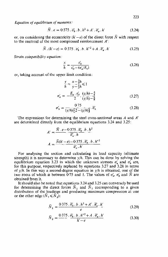
223 Equation of equilibrium of moments:
N . e = 0.375 . ab. b . h2 + A' .a,. h' (3.24)
or, on considering the eccentricity (h'-e) of the direct force N with respect to the centroid of the most compressed reinforcement A' :
Ñ . (h' - e) = 0.375 . O;, . b . h'" + A .a: . h' (3.25)
Strain compatibility equation: _ - X E O - h &-(o:lE,)
or, taking account of the upper limit condition
(3.26)
(3.27)
(3.28)
The expressions for determining the steel cross-sectional areas A and A' are determined directly from the equilibrium equations 3.24 and 3.25 :
N . e-0.375. ob. b . h2 0;. h
N(h' -e) - 0.375 . o;, . b . h"' 3, . h'
For analysing the section and calculating its load capacity (ultimate strength) it is necessary to determine y/h. This can be done by solving the equilibrium equation 3.23 in which the unknown stresses o: and ob are, for this purpose, respectively replaced by equations 3.27 and 3.28 in terms of ylh. In this way a second-degree equation in ylh is obtained, one of the two roots of which is between 0.75 and 1. The values of o:, ob and N are obtained from it.
It should also be noted that equations 3.24 and 3.25 can conversely be used for determining the direct forces N, and N2 corresponding to a given distribution of the loadings and producing maximum compression at one or the other edge (Ñ, < N2):
A' =
A =
- N, = (3.29) 0.375 . O;, . b . h2 + A' .O: . h'
e - N 2 = 0.375. $. b . hff2+A. 0;. h'
h'-e (3.30)
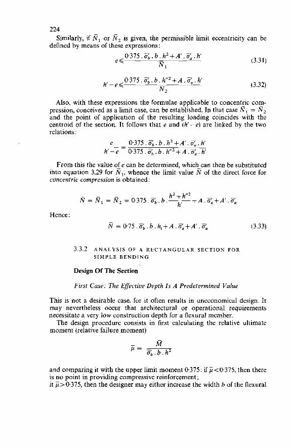
224
defined by means of these expressions : Similarly, if fil or N2 is given, the permissible limit eccentricity can be
0 . 3 7 5 . 6 . b . h2 + A’ . ZL. h’ (3.31) Nl
e <
- (3.32) N2
0.375 .Ob. b . h”’ + A . O:, . h‘ h‘-e<
Also, with these expressions the formulae applicable to concentric com- - pression, conceived as a limit case, can be established. In that case Ñ, = N2 and the point of application of the resulting loading coincides with the centroid of the section. It follows that e and (h’-e) are linked by the two relations :
e h’-e
0.375 .i?; . b . h2 +A‘ . ¿?: . h’ 0.375. 6 . b. h’I2+A.¿?L. h
-- -
From this the value of e can be determined, which can then be substituted into equation 3.29 for NI, whence the limit value N of the direct force for concentric compression is obtained:
N = Ñl = N2 = 0.375.6.b.- h2+h”2+A, $!+A,, h’
Hence : N = 0.75 . ob . b . h, + A .O:, + A‘ . O:, (3.33)
3.3.2 ANALYSIS OF A R E C T A N G U LAR SECTION FOR SIMPLE BENDING
Design Of The Section
First Case: The Effective Depth Is A Predetermined Value
This is not a desirable case, for it often results in uneconomical design. It may nevertheless occur that architectural or operational requirements necessitate a very low construction depth for a flexural member. The design procedure consists in first calculating the relative ultimate
moment (relative failure moment)
and comparing it with the upper limit moment 0.375 : if < 0 3 7 5 , then there is no point in providing compressive reinforcement; it ji>0.375, then the designer may either increase the width b of the flexural
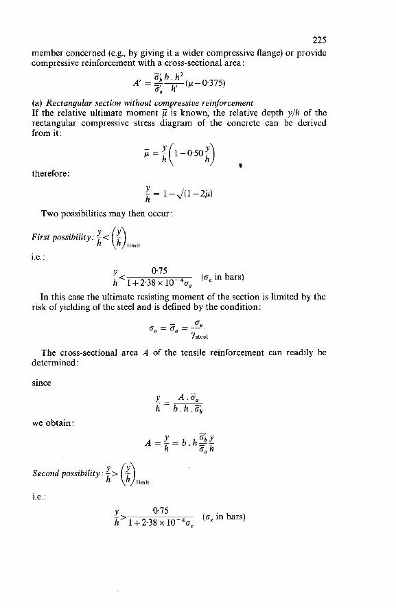
225 member concerned (e.g., by giving it a wider compressive flange) or provide compressive reinforcement with a cross-sectional area :
(a) Rectangular section without compressive reinforcement If the relative ultimate moment is known, the relative depth y/h of the rectangular compressive stress diagram of the concrete can be derived from it:
= !(1-0.50$ * h
therefore:
= 141-2jj) h Two possibilities may then occur:
First possibility: - <
i.e. :
(o, in bars) Y 075 -< h 1 +2.38 x 10-40, In this case the ultimate resisting moment of the section is limited by the
risk of yielding of the steel and is defined by the condition:
- G e ITa = Ga = - Ysieei
The cross-sectional area A of the tensile reinforcement can readily be determined :
since !!-- A .O, h - b . h . 6
we obtain:
Second possibility: - > ($limit
i.e. :
(o, in bars) Y 0.75 h 1 +2.38 x 10⁻⁴~, ->
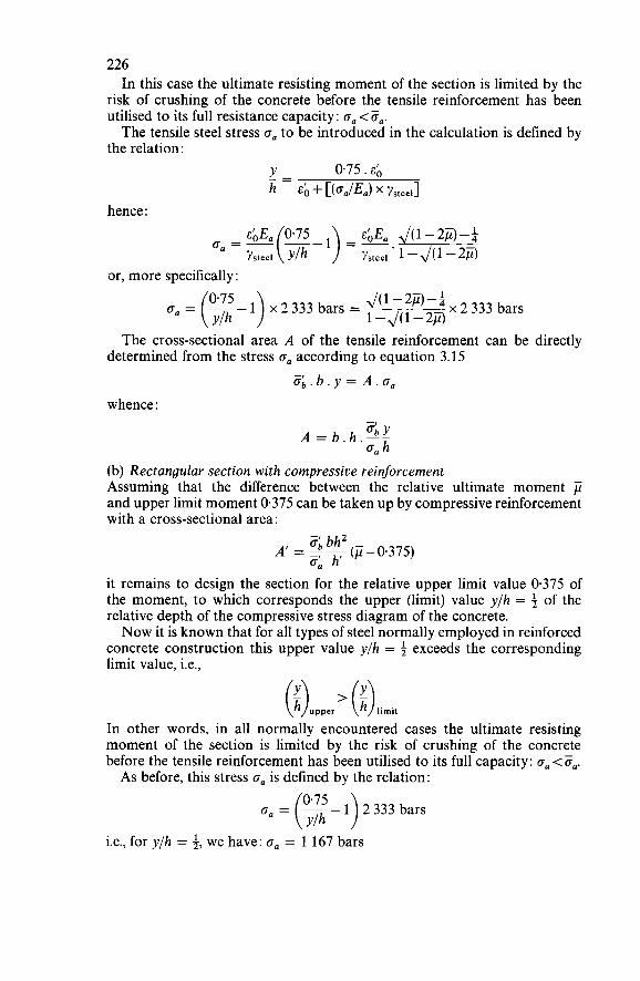
226 In this case the ultimate resisting moment of the section is limited by the
risk of crushing of the concrete before the tensile reinforcement has been utilised to its full resistance capacity: o, <O,. The tensile steel stress oa to be introduced in the calculation is defined by
the relation: Y 0.75 . EO _- h - EO + [(oa/Ea) x ~steel]
hence :
or, more specifically : J(l-2j4-i 1 x2333 bars = x 2 333 bars = (3- ) 1-41-29
The cross-sectional area A of the tensile reinforcement can be directly determined from the stress oa according to equation 3.15
Zb.b.y = A.0, whence :
obY A = b.h.-- G a h
(b) Rectangular section with compressive reinforcement Assuming that the difference between the relative ultimate moment ji and upper limit moment 0.375 can be taken up by compressive reinforcement with a cross-sectional area:
G b h 2 - o: h’ A’ = r-(/.i-0.375)
it remains to design the section for the relative upper limit value 0.375 of the moment, to which corresponds the upper (limit) value y/h = i of the relative depth of the compressive stress diagram of the concrete. Now it is known that for all types of steel normally employed in reinforced
concrete construction this upper value y/h = 3 exceeds the corresponding limit value, i.e.,
In other words, in all normally encountered cases the ultimate resisting moment of the section is limited by the risk of crushing of the concrete before the tensile reinforcement has been utilised to its full capacity: o, <O,. As before, this stress o, is defined by the relation:
= (x- 1 ) 2333 bars i.e., for y/h = 3, we have: o, = 1 167 bars
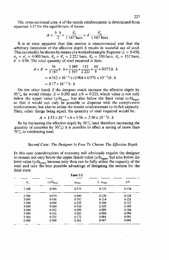
227 The cross-sectional area A of the tensile reinforcement is determined from
equation 3.17 for the equilibrium of forces b.h a:, a:, A=-x 2 1 167 barsfA’ 1 167 bars
It is at once apparent that this section is uneconomical and that the arbitrary limitation of the effective depth h results in wasteful use of steel. This can readily be shown by means of a worked example. Suppose: jï = 0.450, o, = a; = 4 O00 bars, ¿Fa = 0, = 2 222 bars, Zó = 350 bars, 3, = 152 bars, h’ = 0.9h. The total quantity of steel required is then:
76 b.h+- 3389 152 x!!!x0.0’75b.h 1 1 6 7 ’ m 9 A+A’ = - 1167
= 6.512~10-~+(2.904~0.571~ 10-2)b.h = 8.17 x low2 b. h
O n the other hand, if the designer could increase the effective depth by 50%, he would obtain: = 0.200 and y/h = 0.225, which value is not only below the upper value (y/h)upper, but also below the limit value ( y/h)ii,it, so that it would not only be possible to dispense with the compressive reinforcement, but also to utilise the tensile reinforcement to its full capacity. Then, other things being equal, the quantity of steel required would be:
A = 153 x x b x 1.5h = 2.30 x 1OP2b. h So by increasing the effective depth by 50% (and therefore increasing the
quantity of concrete by 50%) it is possible to effect a saving of more than 70 % in reinforcing steel.
Second Case: The Designer Is Free’To Choose The Eflective Depth
In this case considerations of economy will obviously require the designer to remain not only below the upper (limit) value (y/h)Fqp,, but also below the limit value (y/h)li,,,it, because only then can he fully utilise the capacity of the steel and take the best possible advantage of designing the section for the limit state.
Table 3.2
6, (YIh),imi1 Piimi, f . Piimii Ylh
2 100 0500 0,375 0,125 0134
2 500 0.470 0.360 0.120 0128 3 O00 O 438 0,342 0114 0121 3 500 0409 0325 0.108 0115 4 O00 0.384 0.310 0.103 0.109 4 500 0.362 0296 0.099 0104 5 O00 0.342 0.283 0094 0.099 5 500 0.325 0.272 0.09 1 0095 6 O00 0,309 0,261 0.087 0.09 1
228 In the absence of design charts or graphs a reasonable and convenient
solution (but not always the most economical solution) consists in arbitrarily basing oneself on one-third of the limit moment (see Table 3.2). The effective depth h and the cross-sectional area of the tensile reinforce-
ment A can then directly be determined :
6 Y A=b.h.:.- G a h
For example: suppose that for a moment M = 50000 kgm we have ce = 4 O00 bars, Ca = 2 222 bars, ob = 350 bars, ob = 152 bars, b = 0.60 m; we then obtain :
h = J( 5x10⁶ ) = 73cm 0.103 x 152 x 60
152 2 222 A = 60 x 73 x - x 0.109 = 32.6 cm2
i.e., a geometrical percentage of 0.75 %.
Analysis Of The Section
The analysis of a rectangular section with or without compressive reinforce- ment is carried out by applying the general equations 3.12-3.18 in which the direct force is substituted as of zero value, i.e. N = O.
For practical purposes the procedure is as follows :
First Attempt
Calculate the relative depth y/h of the rectangular diagram by means of the formula:
y A.ZO-A'.CL _- (equilibrium equation) h - Zb.b.h
If the value obtained for y/h is below the value of (y/h)ii,it corresponding to the grade of steel used, we have the case where failure is by yielding of the steel, with no upper limit applied to the moment and we must apply equation 3.13, which immediately gives the resisting moment :
= 3,. b . h2 . ?! +A'. O:, . h' (moment equation) h
229 If not, then it means that failure occurs as a result of crushing of the
concrete, not yielding of the steel. It will then be necessary to make a second attempt.
Second Attempt
Calculate the relative depth y/h of the rectangle diagram by solving the following set of equations:
y 0.75. EO _- (compatibility equation) h - EO + (oa/EJ y - A.a,-A'.Z, - (equilibrium equation) h - Zb.b.h
In this way we find the value of oa (lower than O,) and a fresh value of
If the value thus obtained for y/h, while exceeding ( y / Q i m i t , is below the value (y/h)upper = 3, we have the case where failure is by crushing of the concrete, with no upper limit applied to the moment) and we must then, as in the previous case, apply equation 3.13, which immediately gives the resisting moment :
Ylh.
f i = % . b . h Z . ? +A'.%.h' (momentequation) h If, on the other hand, the value obtained for y/h exceeds the value (y/h)upper
= t, the upper limit must be introduced and a third attempt made.
Third Attempt
W e now have the case where failure is by crushing of the concrete, with upper limit applied to the moment). This moment can be directly calculated:
M = 0.375.b.h2.Zb+A'.Za.h'
3.3.3 ANALYSIS OF A RECTANGULAR SECTION F O R COMPOSITE BENDING WITH COMPRESSION
Design Of The Section
First Case: The Effective Depth Is A Predetermined Value
Just as in the case of simple bending, the design procedure consists in first calculating the relative ultimate moment
- N.e j ¿ = - ob. b . h2
and comparing it with the upper limit value of the moment, i.e., 0.375:
230 if ji<0.375, then there is no point in providing compressive reinforcement; if jï> 0.375, then the designer may either increase the width b of the flexural member concerned (e.g.> by giving it a wider compressive flange) or provide compressive reinforcement with a cross-sectional area:
When the compressive steel area A’ is known, the value of y/h can be calculated by application of equation 3.13 :
(3.13)
The value obtained for y/h will then depend upon the value of
N . e - A’ . K . h 6 . b . h 2
- - Za.A’.h ’- Oh . b. h2 -
If the value of ,u is below the upper limit 0.375 or if the difference (p - 0.375) is completely equilibrated by appropriate compressive reinforcement, the value obtained for y/h will be below 0.50 and the strength of the section will be limited either by the risk of failure of the tensile reinforcement if
or by the risk of failure (crushing) of the concrete if
In the alternative case, i.e., if the value of exceeds the upper limit 0.375 while the difference (g-0.375) is not completely equilibrated by the com- pressive reinforcement, the value obtained for y/h will exceed 0.50 and the upper limit condition will have to be applied (0.75 . 3, < ob < ob).
First possibility: -< i,(;) G0.50 limi1
In this case the ultimate resisting moment of the section is limited by the risk of yielding of the steel; it is defined by the condition:
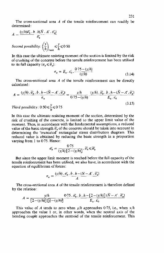
23 1 The cross-sectional area A of the tensile reinforcement can readily be
determined:
A = (y/h)& . b . h(N . A’ . ¿fL) 6
Second possibility: (i) 6i60.50 limit
In this case the ultimate resisting moment of the section is limited by the risk of crushing of the concrete before the tensile reinforcement has been utilised to its full capacity (0,6i?,):
0.75 - (y/h) O, = E,. EO .
(Y/h) (3.14) The cross-sectional area A of the tensile reinforcement can be directly
calculated :
y/h (y/h) .ab . b . h - (N - A‘. <) - - (y/h).%.b. h-(N-A’.&) C a 0,75-(y/h) ’ E,. EO A =
(3.15) Third possibility: 0.50<!<0.75
In this case the ultimate resisting moment of the section, determined by the risk of crushing of the concrete, is limited to the upper limit value of the moment. Then, in accordance with the fundamental assumptions, a reduced value of the basic strength Ob of the concrete should be taken into account in determining the ‘truncated’ rectangular stress distribution diagram. This reduced value is obtained by reducing the basic strength in a proportion varying from 1 to 0.75. Hence:
h‘
But since the upper limit moment is reached before the full capacity of the tensile reinforcement has been utilised, we also have, in accordance with the equation of equilibrium of forces:
(y/h).üb.b.h-(N-A’.O,) A 0, =
The cross-sectional area A of the tensile reinforcement is therefore defined by the relation:
A = Y/h 075. Zb. b . h- [2-(y/h)] (N-A’ . 3) [2 - (Y/h)l - (Y/h)l E,. EO
This value of A tends to zero when y/h approaches 0.75, i.e., when x/h approaches the value 1 or, in other words, when the neutral axis of the bending couple approaches the centroid of the tensile reinforcement. This
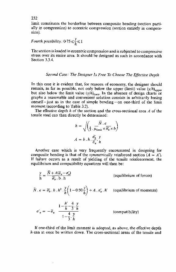
232 limit constitutes the borderline between composite bending (section parti- ally in compression) to eccentric compression (section entirely in compres- sion).
Fourth possibility: 0.75<-< Y 1 h‘
The section is loaded in eccentric compression and is subjected to compressive stress over its entire area. It should be designed as such in accordance with Section 3.3.4.
Second Case: The Designer Is Free To Choose The Effective Depth
In this case it is evident that, for reasons of economy, the designer should remain, as far as possible, not only below the upper (limit) value (y/h),,,,, but also below the limit value (y/h),imit. In the absence of design charts or graphs a reasonable and convenient solution consists in arbitrarily basing oneself-just as in the case of simple bending-on one-third of the limit moment (according to Table 3.2). The effective depth h of the section and the cross-sectional area A of the
tensile steel can then directly be determined :
-I ‘b Y A = b.h.:.- ‘a h
Another case which is very frequently encountered in designing for composite bending is that of the symmetrically reinforced section (A = A’). If failure occurs as a result of yielding of the tensile reinforcement, the equilibrium and compatibility equations will then be :
(equilibrium of forces)
Ñ . e = ob. b . h2 . f + A . o; . h‘ (equilibrium of moments) h
h’ 4 y I---- - - h 3 ’ h da = -6,
I-- 4 Y - 3 ’ h
(compatibility)
If one-third of the limit moment is adopted, as above, the effective depth h can at once be written down. The cross-sectional areas of the tensile and
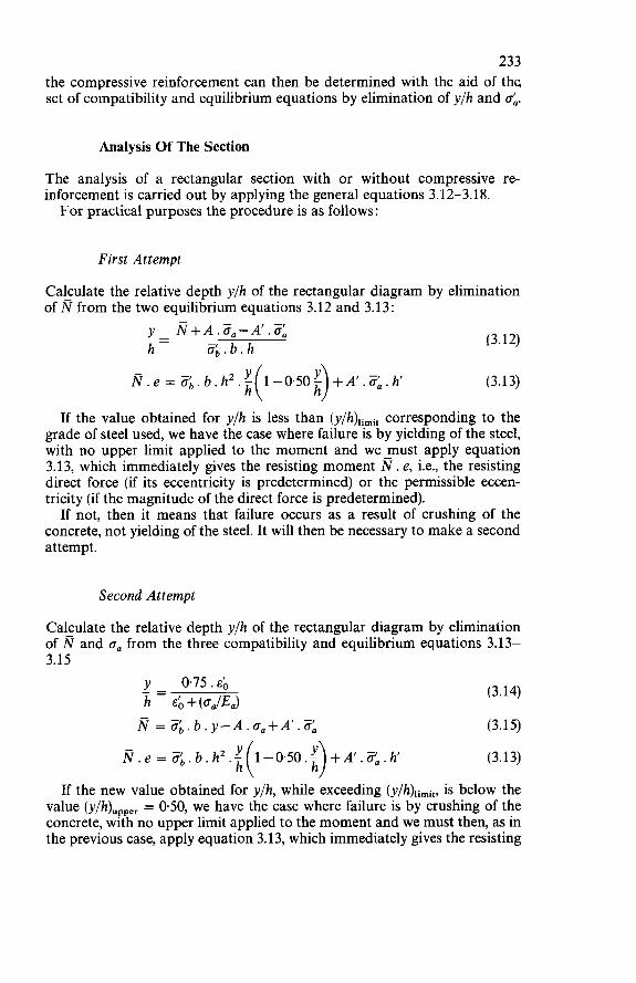
233 the compressive reinforcement can then be determined with the aid of the set of compatibility and equilibrium equations by elimination of y/h and o;.
Analysis Of The Section
The analysis of a rectangular section with or without compressive re- inforcement is carried out by applying the general equations 3.12-3.18. For practical purposes the procedure is as follows :
First Attempt
Calculate the relative depth y/h of the rectangular diagram by elimination of N from the two equilibrium equations 3.12 and 3.13:
N . e = Zb.b.h2.1 h
13.12)
(3.13)
If the value obtained for y/h is less than ( ~ / h ) , ~ ~ ~ , corresponding to the grade of steel used, we have the case where failure is by yielding of the steel, with no upper limit applied to the moment and we must apply equation 3.13, which immediately gives the resisting moment N . e, i.e., the resisting direct force (if its eccentricity is predetermined) or the permissible eccen- tricity (if the magnitude of the direct force is predetermined). If not, then it means that failure occurs as a result of crushing of the
concrete, not yielding of the steel. It will then be necessary to make a second attempt.
Second Attempt
Calculate the relative depth y/h of the rectangular diagram by elimination of N and 6, from the three compatibility and equilibrium equations 3.13- 3.15
(3.14)
N = %.b.y-A.oa+A’.% (3.15)
N . e = Zb. b . h2.J h (3.13)
If the new value obtained for y/h, while exceeding (~/h),¡~¡~, is below the value (y/h),,,,, = 0.50, we have the case where failure is by crushing of the concrete, with no upper limit applied to the moment and we must then, as in the previous case, apply equation 3.13, which immediately gives the resisting
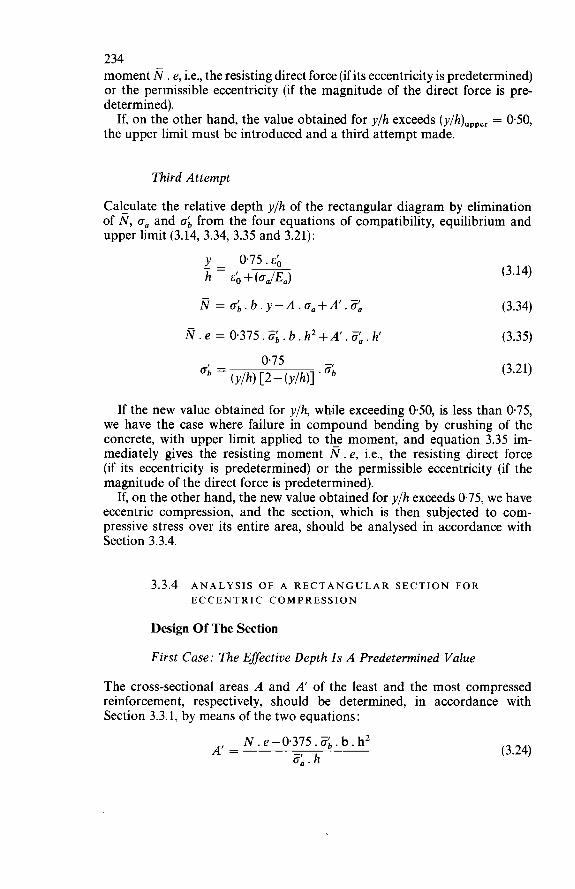
234 moment Ñ . e, i.e., the resisting direct force (if its eccentricity is predetermined) or the permissible eccentricity (if the magnitude of the direct force is pre- determined). If, on the other hand, the value obtained for y/h exceeds (y/h)upper = 0.50,
the upper limit must be introduced and a third attempt made.
Third Attempt
Calculate the relative depth y/h of the rectangular diagram by elimination of Ñ, O, and o: from the four equations of compatibility, equilibrium and upper limit (3.14, 3.34, 3.35 and 3.21):
y 0.75. EO _ - h - E O + (o,/&) (3.14)
N = r&.b.y-A.o,+A'.& (3.34)
Ñ.e = 0.375.6.b.h2+A'.&.h (3.35)
075 Ob = (y/h) [2-(y/h)] ' ob (3.21)
If the new value obtained for y/h, while exceeding 0.50, is less than 0.75, we have the case where failure in compound bending by crushing of the concrete, with upper limit applied to the moment, and equation 3.35 im- mediately gives the resisting moment N. e, i.e., the resisting direct force (if its eccentricity is predetermined) or the permissible eccentricity (if the magnitude of the direct force is predetermined).
If, on the other hand, the new value obtained for y/h exceeds 0.75, we have eccentric compression, and the section, which is then subjected to com- pressive stress over its entire area, should be analysed in accordance with Section 3.3.4.
3.3.4 ANALYSIS OF A RECTANGULAR SECTION F O R ECCENTRIC COMPRESSION
Design Of The Section
First Case: The Effective Depth Is A Predetermined Value
The cross-sectional areas A and A' of the least and the most compressed reinforcement, respectively, should be determined, in accordance with Section 3.3.1, by means of the two equations:
(3.24) N . e-0.375.6. b. h2 3, . h
A' =
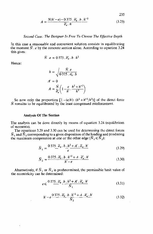
235
(3.25) Ñ(h‘-e)-0.375. O;, . b. h” A = 6á.h
Second Case: The Designer Is Free To Choose The Effective Depth
In this case a reasonable and convenient solution consists in equilibrating the moment Ñ . e by the concrete section alone. According to equation 3.24 this gives:
Ñ.e=0375.0;,.b.h2
Hence :
Ñ. e = dû.375. ob. b
A‘ = O
So now only the proportion [ 1 - (e/h’) . (h2 + h”’/h2)] of the direct force N remains to be equilibrated by the least compressed reinforcement.
Analysis Of The Section
The analysis can be done directly by means of equation 3.24 (equilibrium of moments). The equations 3.29 and 3.30 can be used for determining the direct forces
NI and Nz corresponding to a given disposition of the loadiq and producing the maximum compression at one or the other edge (Ni <IV2):
- N, = 0.375. ¿?b. b. h2+A‘. O,. h e
0.375. ob. b. h”’+A. 8. h h’-e
- N 2 =
(3.29)
(3.30)
Alternatively, if NI or Nz is predetermined, the permissible limit value of the eccentricity can be determined:
0.375. Zb. b . h2+A’. &. h‘ NI e< (3.31)
(3.32) 0.375 . zb, b . h“’ + A .¿?: . h‘ h - e N2
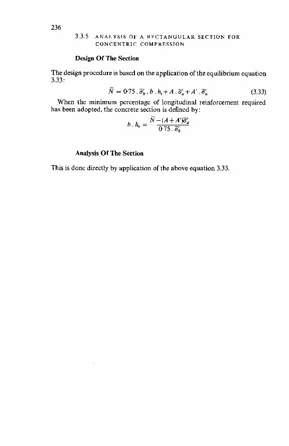
236 3.3.5 ANALYSIS OF A RECTANGULAR SECTION FOR
CONCENTRIC COMPRESSION
Design Of The Section
The design procedure is based on the application of the equilibrium equation 3.33 :
N = 0.75.Zb.b.h,+A.<+A’.% (3.33) When the minimum percentage of longitudinal reinforcement required
has been adopted, the concrete section is defined by: N - (A + A’)% b a h , = 0.75. Zb
Analysis Of The Section
This is done directly by application of the above equation 3.33.
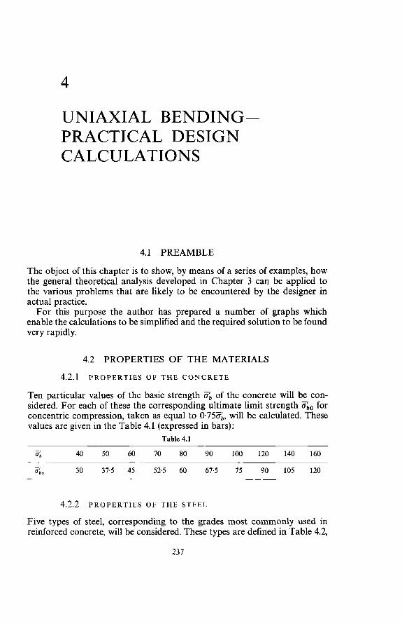
4
UNIAXIAL BENDING- PRACTICAL DESIGN CALCULATIONS
4.1 PREAMBLE
The object of this chapter is to show, by means of a series of examples, how the general theoretical analysis developed in Chapter 3 can be applied to the various problems that are likely to be encountered by the designer in actual practice. For this purpose the author has prepared a number of graphs which
enable the calculations to be simplified and the required solution to be found very rapidly.
4.2 PROPERTIES OF THE MATERIALS 4.2.1 PROPERTIES OF THE CONCRETE
Ten particular values of the basic strength ab of the concrete will be con- sidered. For each of these the corresponding ultimate limit strength %o for concentric compression, taken as equal to 0.75Zb, will be calculated. These values are given in the Table 4.1 (expressed in bars):
Table 4.1
Zb 40 50 60 70 80 90 100 120 140 160
30 37.5 45 52.5 60 67.5 75 90 105 120 - 4.
4.2.2 PROPERTIES OF THE STEEL
Five types of steel, corresponding to the grades most commonly used in reinforced concrete, will be considered. These types are defined in Table 4.2,
237
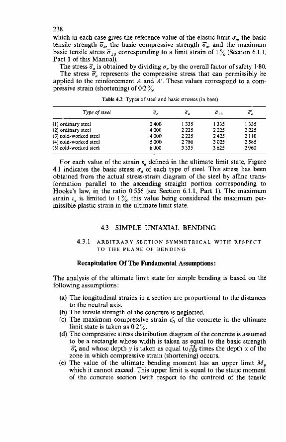
238 which in each case gives the reference value of the elastic limit oe, the basic tensile strength O,, the basic compressive strength 3,, and the maximum basic tensile stress Zio corresponding to a limit strain of 1 % (Section 6.1.1, Part 1 of this Manual). The stress 0, is obtained by dividing oe by the overall factor of safety 1.80. The stress 3, represents the compressive stress that can permissibly be
applied to the reinforcement A and A’. These values correspond to a com- pressive strain (shortening) of 0.2 %.
Table 4.2 Types of steel and basic stresses (in bars)
- - - - Type of steel ce 0 0 O10 4
(1) ordinary steel 2 400 1335 1335 1335 (2) ordinary steel 4 O00 2 225 2 225 2 225 (3) cold-worked steel 4 O00 2 225 2 425 2 110 (4) cold-worked steel 5 O00 2 780 3 025 2 585 (5) cold-worked steel 6 O00 3 335 3 625 2 960
For each value of the strain E, defined in the ultimate limit state, Figure 4.1 indicates the basic stress oa of each type of steel. This stress has been obtained from the actual stress-strain diagram of the steel by affine trans- formation parallel to the ascending straight portion corresponding to Hooke’s law, in the ratio 0.556 (see Section 6.1.1, Part 1). The maximum strain E, is limited to i%, this value being considered the maximum per- missible plastic strain in the ultimate limit state.
4.3 SIMPLE UNIAXIAL BENDING
4.3.1 ARBITRARY SECTION SYMMETRICAL WITH RESPECT TO THE PLANE OF BENDING
Recapitulation Of The Fundamental Assumptions :
The analysis of the ultimate limit state for simple bending is based on the following assumptions :
(a) The longitudinal strains in a section are proportional to the distances
(b) The tensile strength of the concrete is neglected. (c) The maximum compressive strain E; of the concrete in the ultimate
limit state is taken as 0.2 %. (d) The compressive stress distribution diagram of the concrete is assumed
to be a rectangle whose width is taken as equal to the basic strength ab and whose depth y is taken as equal to,&$, times the depth x of the zone in which compressive strain (shortening) occurs.
(e) The value of the ultimate bending moment has an upper limit M, which it cannot exceed. This upper limit is equal to the static moment of the concrete section (with respect to the centroid of the tensile
to the neutral axis.
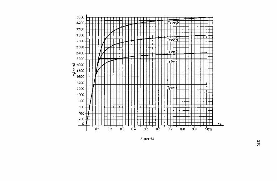
239
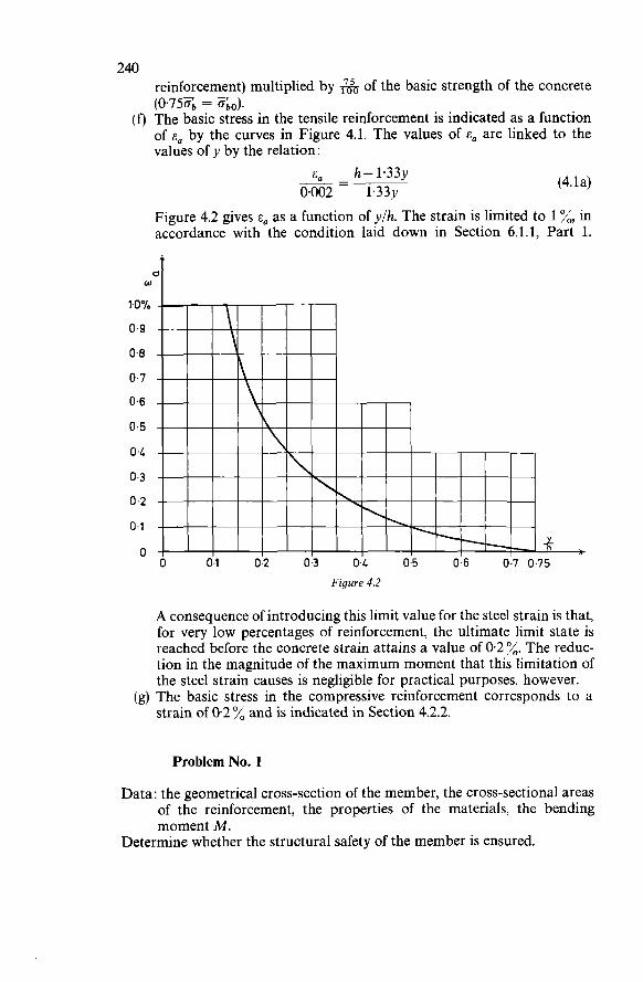
240 reinforcement) multiplied by 6 of the basic strength of the concrete
(f) The basic stress in the tensile reinforcement is indicated as a function of E, by the curves in Figure 4.1. The values of E, are linked to the values of y by the relation :
(0’750b = 0bo).
E,- h- 1.33~ 0002 - 1.33~ (4.la)
Figure 4.2 gives E, as a function of ylh. The strain is limited to 1 %, in accordance with the condition laid down in Section 6.1.1, Part 1.
w
1~0%
0.9
0-8
0.7
0.6
0.5
04
0.3
o .2 0.1
O
Figure 4.2
A consequence of introducing this limit value for the steel strain is that, for very low percentages of reinforcement, the ultimate limit state is reached before the concrete strain attains a value of 0.2 %. The reduc- tion in the magnitude of the maximum moment that this limitation of the steel strain causes is negligible for practical purposes, however.
(g) The basic stress in the compressive reinforcement corresponds to a strain of 0.2 % and is indicated in Section 4.2.2.
Problem No. 1
Data: the geometrical cross-section of the member, the cross-sectional areas of the reinforcement, the properties of the materials, the bending moment M.
Determine whether the structural safety of the member is ensured.
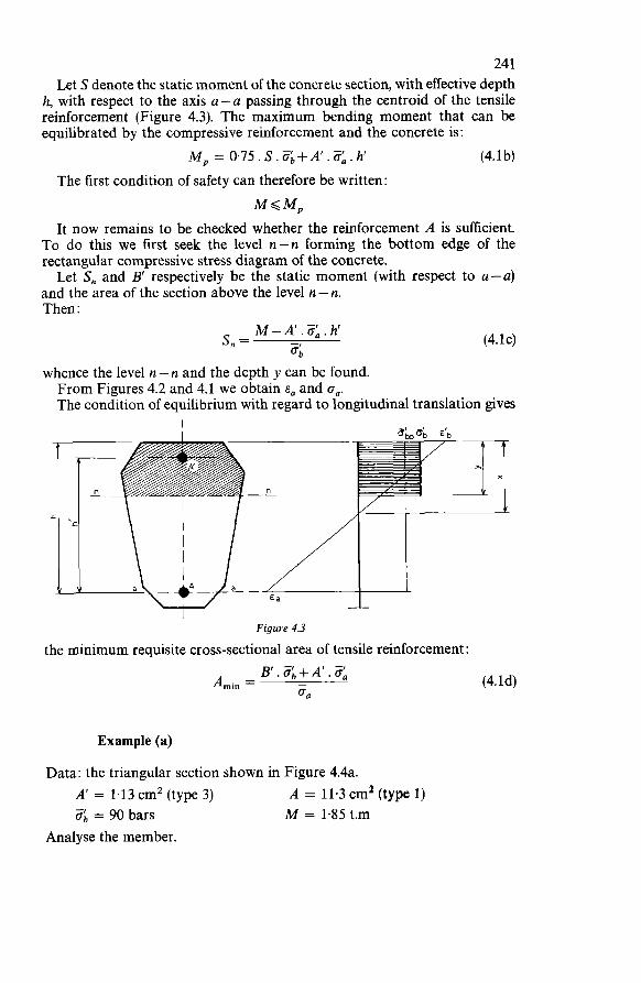
24 1 Let S denote the static moment of the concrete section, with effective depth
h, with respect to the axis u-u passing through the centroid of the tensile reinforcement (Figure 4.3). The maximum bending moment that can be equilibrated by the compressive reinforcement and the concrete is:
M, = 0.75.S.Zb+A’.Zá.h (4.1 b) The first condition of safety can therefore be written:
MGM, It now remains to be checked whether the reinforcement A is sufficient.
To do this we first seek the level n-n forming the bottom edge of the rectangular compressive stress diagram of the concrete. Let S, and B’ respectively be the static moment (with respect to u-u)
and the area of the section above the level n - n. Then :
M -A‘. 0;. h‘ s, = $I,
(4.1~)
whence the level n - n and the depth y can be found. From Figures 4.2 and 4.1 we obtain E, and on. The condition of equilibrium with regard to longitudinal translation gives
I
Figure 4.3
the minimum requisite cross-sectional area of tensile reinforcement:
Example (a)
(4.ld)
Data: the triangular section shown in Figure 4.4a. A’ = 1.13 cm2 (type 3) 6 = 90 bars
Analyse the member.
A = 11.3 cm’ (type 1) M = 1.85 t.m
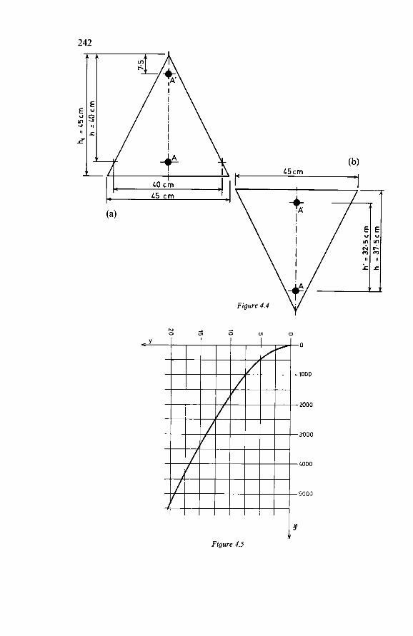
242
E, m .a I,
i
O Ln O N 2 O Ln
I’ Figure .1.5
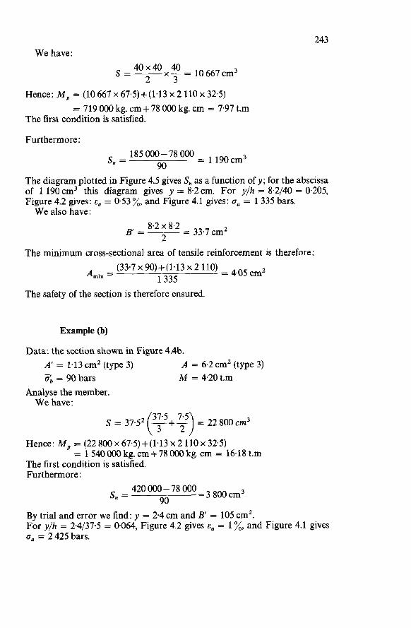
243 We have :
40x40 40 2 3 s=- x - = 10 667 cm3
Hence: M, = (10 667 x 67.5)+(1.13 x 2 110 x 32.5)
The first condition is satisfied. = 719 O00 kg. cm + 78 O00 kg. c m = 7.97 t.m
Furthermore : 185000-78000 = 190cm3
90 s, = The diagram plotted in Figure 4.5 gives S, as a function of y; for the abscissa of 1 190cm3 this diagram gives y = 8.2cm. For y/h = 8.2/40 = 0.205, Figure 4.2 gives: E, = 0.53 %, and Figure 4.1 gives: o. = 1 335 bars. We also have:
The minimum cross-sectional area of tensile reinforcement is therefore:
The safety of the section is therefore ensured.
Example (b)
Data: the section shown in Figure 4.4b. A' = 1.13 cm2 (type 3) 0; = 90 bars
Analyse the member.
A = 6.2 cm2 (type 3) M = 4.20 t.m -
We have :
S = 37.S -+- = 22 800 em3 (3i5 2') Hence: M, = (22 800 x 67.5)+(1.13 x 2 110 x 32.5) The first condition is satisfied. Furthermore:
= 1540000kg.cm+78000kg.cm = 16.18t.m
420 O00 - 78 O00 - 8oo cm3 90 s, =
By trial and error we find: y = 2.4 c m and B' = 105 cm'. For y/h = 2.4/37.5 = 0.064, Figure 4.2 gives E, = 1 %, and Figure 4.1 gives o, = 2 425 bars.
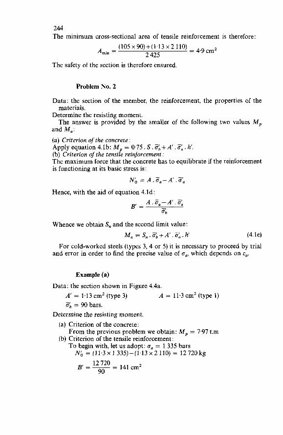
244 The minimum cross-sectional area of tensile reinforcement is therefore :
(105x90)+(1~13~2110) = 4.9cmz A . = min 2 425 The safety of the section is therefore ensured.
Problem No. 2
Data: the section of the member, the reinforcement, the properties of the
Determine the resisting moment.
and Ma: (a) Criterion of the concrete: Apply equation 4.lb: M, = 0.75 . S. $b + A’ . 3, . h’. (b) Criterion of the tensile reinforcement: The maximum force that the concrete has to equilibrate if the reinforcement is functioning at its basic stress is:
materials.
The answer is provided by the smaller of the following two values M,
Nó = A.Z,-A‘.Z, Hence, with the aid of equation 4.ld:
Whence we obtain S, and the second limit value: Ma = S,.Zb+A‘.&.h (4.le)
For cold-worked steels (types 3,4 or 5) it is necessary to proceed by trial and error in order to find the precise value of o,, which depends on E,.
Example (a)
Data: the section shown in Figure 4.4a. A’ = 1.13 cmz (type 3) ab = 90 bars.
Determine the resisting moment. (a) Criterion of the concrete:
(b) Criterion of the tensile reinforcement:
A = 11.3 cm’ (type 1) -
From the previous problem we obtain: M, = 7.97 t.m
To begin with, let us adopt: a. = 1 335 bars Nó = (11.3 x 1335)-(1.13 ~2 110) = 12 720 kg
- 141cmZ 12 720 90
BI=--
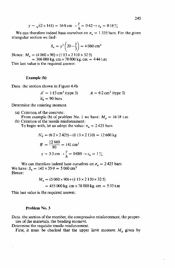
245 y = J(2 x 141) = 16.8 cm + Y - = 0.42 -* E, = 0.16 %
h W e can therefore indeed base ourselves on oa = 1 335 bars. For the given
triangular section we find :
Hence: Ma = (4060x90)+(1.13~2 110~32.5)
This last value is the required answer. = 366 O00 kg. cm + 78 O00 kg. cm = 4.44 t.m
Example (b)
Data: the section shown in Figure 4.4b A’ = 1.13 cm2 (type 3) ob = 90 bars
A = 6.2cm2 (type 3)
Determine the resisting moment.
(a) Criterion of the concrete:
(b) Criterion of the tensile reinforcement: From example (b) of problem No. 1 we have: M, = 16.18 t.m
To begin with, let us adopt the value: oa = 2 425 bars
Nó = (6.2 x 2 425) - ( 1.1 3 x 2 1 10) = 12 660 kg
y = 3.3cm+-=O.O88+~,= Y 1% h
W e can therefore indeed base ourselves on o, = 2 425 bars W e have: S, = 141 x 35.9 = 5 060 cm3 Hence :
Ma = (5060~90)+(1.13~2 110~32.5) = 455 O00 kg. cm + 78 O00 kg. cm = 5.33 t.m
This last value is the required answer.
Problem No. 3
Data: the section of the member, the compressive reinforcement, the proper- ties of the materials, the bending moment.
Determine the requisite tensile reinforcement. First, it must be checked that the upper limit moment M, given by
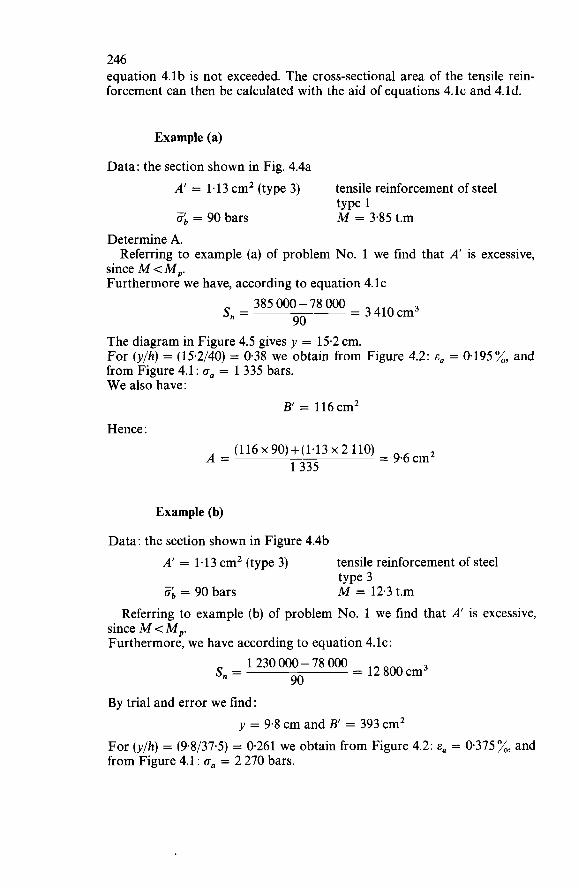
246 equation 4.lb is not exceeded. The cross-sectional area of the tensile rein- forcement can then be calculated with the aid of equations 4.lc and 4.ld.
Example (a)
Data: the section shown in Fig. 4.4a A’ = 1.13 cm2 (type 3) 8, = 90 bars
tensile reinforcement of steel
M = 3.85 t.m type 1
Determine A.
since M < M,. Furthermore we have, according to equation 4. IC
Referring to example (a) of problem No. 1 we find that A’ is excessive,
385 O00 - 78 O00 = 410 cm3 90 s, = The diagram in Figure 4.5 gives y = 15.2 cm. For (y/h) = (15.2/40) = 0.38 we obtain from Figure 4.2: E, = 0.195%, and from Figure 4.1 : o, = 1 335 bars. W e also have:
B’ = 116 cm2 Hence :
(116 x 90)+(1’13 x 2 Ilo) = 9.6 cm2 1335 A =
Example (b)
Data: the section shown in Figure 4.4b A’ = 1.13 cm2 (type 3)
Zb = 90 bars
tensile reinforcement of steel
M = 12.3 t.m type 3
Referring to example (b) of problem No. 1 we find that A’ is excessive, since M < M,. Furthermore, we have according to equation 4. IC :
1 230 O00 - 78 O00 = 12 cm3 90 s, =
By trial and error we find: y = 9.8 cm and B’ = 393 cm2
For (y/h) = (9.8/37.5) = 0.261 we obtain from Figure 4.2: E, = 0.375 %, and from Figure 4.1 : o, = 2 270 bars.
247 Hence
(393~90)+(1.13~2110) = 16,7cm2 2 260 A =
Problem No. 4
Data: the section of the member, the compressive reinforcement, the proper-
Determine the minimum strength of the concrete, the corresponding tensile reinforcement.
ties of the reinforcement, the bending moment.
Equation 4.1 b can be transformed to :
M- A’. O:, . h‘ ob = 0.75s (4.19
The minimum requisite strength of the concrete can thus be directly determined. O n substituting this stress in equation 4.lc and using equation 4.ld,
we obtain the requisite cross-sectional area of the tensile reinforcement. For certain cross-sectional shapes it may occur that this calculation leads
to a value of y very close to 075h or even in excess of this limit. In that case E, will have a very low value, which may even be negative, so that there would be no reasonable solution to the problem considered in this way. In order to obtain a fair efficiency of the tensile reinforcement, it is advisable
not to let E, go below 0.1 %, which limits y/h to 0.50 (cf. Figure 4.2). With the aid of equation 4.lc written in the following form:
M -A’. Zá. h’ = s n
we can determine the minimum concrete strength corresponding to this new position of the neutral axis. It should be noted that it may be economically advantageous further to
increase E, if the resulting reduction in the steel area A compensates for the extra cost of using a concrete of better quality (i.e., higher strength).
Example (a)
Data: the section shown in Figure 4.4a A’ = 1.13 cm2 (type 3) M = 3.85 t.m
tensile reinforcement of steel type 1
Determine ob and A.
248 From equation 4.lf we obtain:
- 3 85 O00 - ( 1.13 x 2 1 10 x 32.5) 0.75 x 10 667 a; =
= 38.4 bars Equation 4. IC gives :
307 O00 38.4 S, = ~ = 8 O00 cm3
Hence: y = 27 cm This value exceeds 0.50 h, so that the solution is of no interest. Instead, we shall choose: E, = 0.1 %, which corresponds to O, = 1 335 bars. W e have: ylh = 0.50 and hence: y = 20cm and S, = 5 333 cm3. Hence :
202 - 57.5 bars and B' = - = 200cm2 -1 307 O00 Ob=-- 2
(200~57.5)+(1.13~2 110) = 10,4cm2 1350 A =
Example (b)
Data: the section shown in Figure 4.4b A' = 1.13 cm2 (type 3) M = 12.3 t.m
From equation 4.lf we obtain:
tensile reinforcement of steel type 3
Determine ob and A.
- 1230OO0-(1~13 ~2 110~ 32.5) 0.75 x 22 800 0; =
= 67.5 bars Equation 4. IC gives :
By trial and error we find: y = 15.4 cm Hence :
Figure 4.2 gives: E, = 0.17 %, and Figure 4.1 gives: O, = 2 080 bars W e also have: B' = 575 cm2
249 Hence :
(575 x 675)+(1.13 x 2 110) = 20,0cmz 2 080 A =
In conclusion it should be noted that in example (b) of problem No. 3 we found, for the same member, a value 16.7 cmz for A because a value of 90 bars had been presupposed for #b. This serves to show the saving in steel that can be effected by using a better quality (i.e., stronger) concrete.
Problem No. 5
Data: the section of the member, the strength of the concrete, the cross-
Determine the minimum strength that the reinforcement should have. W e shall decide upon the type of compressive reinforcement to use, taking care not to exceed the upper limit value of the moment given by equation 4.1 b. The further procedure is as indicated in problem No. 3, for which purpose
equation 4.ld is written in the form:
sectional area of the reinforcement, the bending moment.
B' . %+A' . o:, A Gamin = (4.lh)
With E, known, the suitable types of steel can be determined from Figure 4.1.
Example (a)
Data: the section shown in Figure 4.4a.
A' = 1.13cm2 A = 5.3 cmz
- o; = 90 bars M = 3.85 t.m
Determine which types of steel are suitable. Choose steel type 3 for the compressive reinforcement
M, = (10 667 x 67.5)+(143 x 2 110 x 32.5) = 7.97 t.m
Equation 4.lc gives: 385 000- 78 O00 = 410 cm3 90 s, =
Hence :
y = 15.2 cm ?! = 0.38 h B' = 116 cmz
Figure 4.2 gives: E, = 0.195 %
250 From equation 4.lh we obtain:
Figure 4.1 shows that the tensile reinforcement can suitably be of type 4 or 5.
Example (b)
Data: the section shown in Figure 4.4b A’ = 1.13 cm2 A = 17.5cm2
ab = 90 bars M = 12.3 t.m
Determine which types of steel are suitable. Choose steel type 3 for the compressive reinforcement :
M, = (22800~67~5)+(1~13~2110~32~5) = 16.18t.m Equation 4.lc gives:
1 230 O00 - 78 O00 = 12 cm3 90 S” =
By trial and error we find: y = 9.8 cm and B = 393 cm2 For ylh = 9.8137.5 = 0.261, Figure 4.2 gives: E, = 0.375%. Furthermore, equation 4.1 h gives :
(393 x 90)+(1.13 x 2 110) = 150 bars 17.5 gamin = Figure 4.1 shows that all types of steel, except type 1, are suitable.
Problem No. 6
Data: the properties of the materials, the bending moment. Determine the requisite cross-section of the member and the cross-sectional areas of the reinforcement. A direct solution of this problem is not possible. It is necessary to begin
by assuming a concrete section which appears suitable and then finding the reinforcement that is required. Next, it must be investigated whether the reinforcement thus obtained presents a rational and economical solution. In addition, it must be verified that the safety with regard to cracking
and with regard to deformation is duly ensured, i.e., the limit states of cracking and deformation must be checked.
4.3.2 RECTANGU L A R SECTION w ITHOUT COMPRESS I V E REINFORCEMENT
The general method set forth in Section 4.3.1 will be applied, introducing A‘ = O. Let b denote the width of the rectangular section.

Figure 4.6

252 Then :
S = 0.5 b . h2 and S, = b . y (h-0.5~) The upper limit value of the moment is therefore:
M, = 0.5 b . h2. Zbo = 0.375 b . h2. aI, (4.2a)
Knowing the actual bending moment M (which obviously must not exceed this upper limit) we can apply equation 4.lc), which becomes:
This second-degree equation gives y ; we can then directly find the lever arm of the internal forces:
z = h - 0 . 5 ~
The problems can be solved very easily by means of the set of graphs in
From these graphs we can so determine the coefficient 6 that: Figure 4.6.
h = 6J(T) (4.2b)
where the units employed are the cm and the kg. The family of curves drawn as full lines correspond to a range of values of
o'b (in bars). The ratios z/h and y/h are obtained as ordinates associated with these curves. From the curves drawn as dotted lines in the right-hand part of Figure 4.6
the steel stress ca can be determined as a function of the type of steel and of the ratio y/h. The values of oa are marked on the horizontal scale at the top of the diagram. The requisite cross-sectional area of tensile reinforcement is given by :
M A=- z . ca (4.2~)
With Figure 4.6 it is possible to solve the analysis and design problems normally encountered in actual practice.
Problem No. 7
Data: b, h, A, grade of steel, M. Determine the requisite minimum ab. First we determine:
(4.2d)
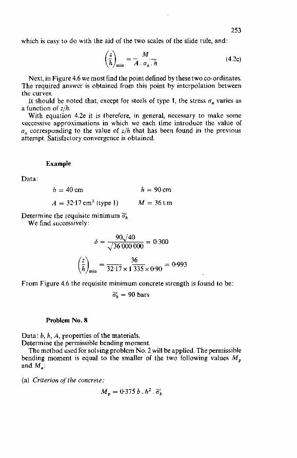
253 which is easy to do with the aid of the two scales of the slide rule, and:
M (i)min = K h (4.2e)
Next, in Figure 4.6 we must find the point defined by these two co-ordinates. The required answer is obtained from this point by interpolation between the curves. It should be noted that, except for steels of type 1, the stress oa varies as
a function of z/h. With equation 4.2e it is therefore, in general, necessary to make some
successive approximations in which we each time introduce the value of oa corresponding to the value of z/h that has been found in the previous attempt. Satisfactory convergence is obtained.
Example
Data : b = 40cm h = 90cm A = 32.17cm2 (type I) M = 36 t.m
Determine the requisite minimum ob W e find successively :
= 0.300 90J40 = ~36000000
= 0.993 36 (i)min = 32.17 x 1 335 x 0.90 From Figure 4.6 the requisite minimum concrete strength is found to be:
- ob = 90 bars
Problem No. 8
Data: b, h, A, properties of the materials. Determine the permissible bending moment. The method used for solving problem No. 2 will be applied. The permissible
bending moment is equal to the smaller of the two following values M, and M,:
(a) Criterion of the concrete: M, = 0.315 b. h2. 6
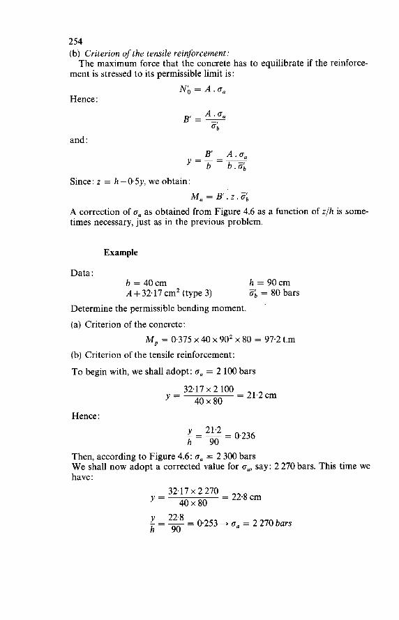
254 (b) Criterion ofthe tensile reinforcement:
ment is stressed to its permissible limit is:
Hence :
The maximum force that the concrete has to equilibrate if the reinforce-
Nó = A.0,
and : B’ A.o, y=-=- b b.Zb
Since: z = h-0.5y, we obtain: Ma = B’ . z . Zb
A correction of o, as obtained from Figure 4.6 as a function of z/h is some- times necessary, just as in the previous problem.
Example
Data: h = 90cm o; = 80 bars - b = 40cm
A + 32.17 cm2 (type 3) Determine the permissible bending moment. (a) Criterion of the concrete:
M, = 0.375 x 40 x 902 x 80 = 97.2 t.m (b) Criterion of the tensile reinforcement:
To begin with, we shall adopt: o, = 2 100 bars
= 21.2cm 32.17 x 2 100 y = 40x80
Hence : y 21.2 - = 0.236 h 90
Then, according to Figure 4.6: o, = 2 300 bars W e shall now adopt a corrected value for o,, say: 2 270 bars. This time we have :
= 22.8 cm 32.17 x 2 270 y = 40 x 80 y h - 90 22’8 - 0253 4 o, = 2 270 bars
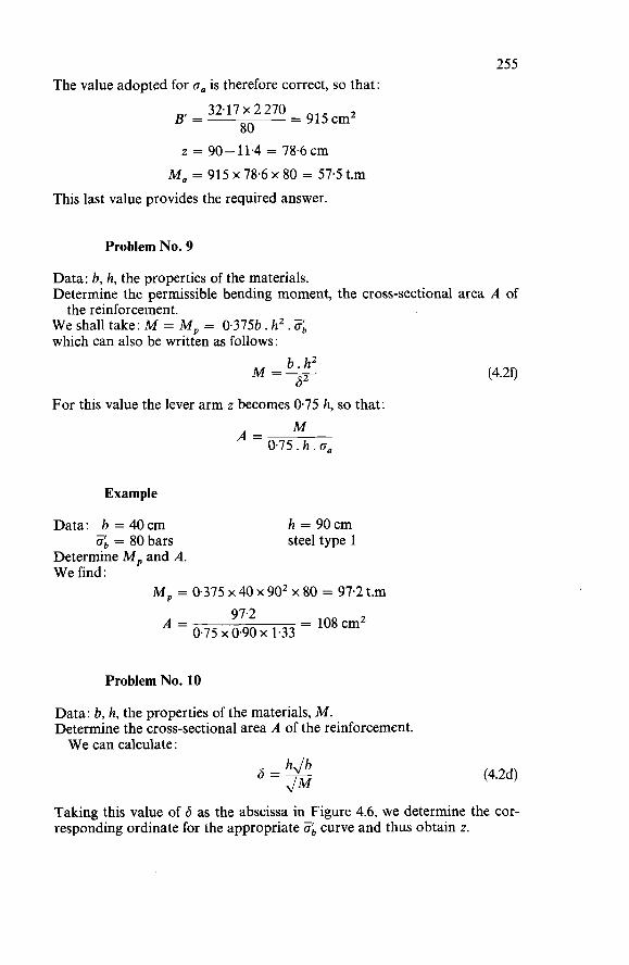
255 The value adopted for o, is therefore correct, so that:
= 915cm2 32.17 x 2 270 80
B’=
z = 90- 11.4 = 78.6 cm M, = 915 x 78.6 x 80 = 57.5 t.m
This last value provides the required answer.
Problem No. 9
Data: b, h, the properties of the materials. Determine the permissible bending moment, the cross-sectional area A of
We shall take: M = M, = 0.375b. h2. 6 which can also be written as follows:
the reinforcement.
b.hz b2
M=-
For this value the lever arm z becomes 0.75 h, so that: M
0.75. h . oa A =
Example
Data: b = 40cm h = 90cm steel type 1
Determine M, and A. We find:
Zb = 80 bars
M, = 0.375 x 40 x 90’ x 80 = 97.2 t.m = 108cm2 97.2
0.75 x 0.90 x 1.33 A =
Problem No. 10
Data: b, h, the properties of the materials, M. Determine the cross-sectional area A of the reinforcement. We can calculate:
(4.2d)
Taking this value of 6 as the abscissa in Figure 4.6, we determine the cor- responding ordinate for the appropriate Z, curve and thus obtain z.
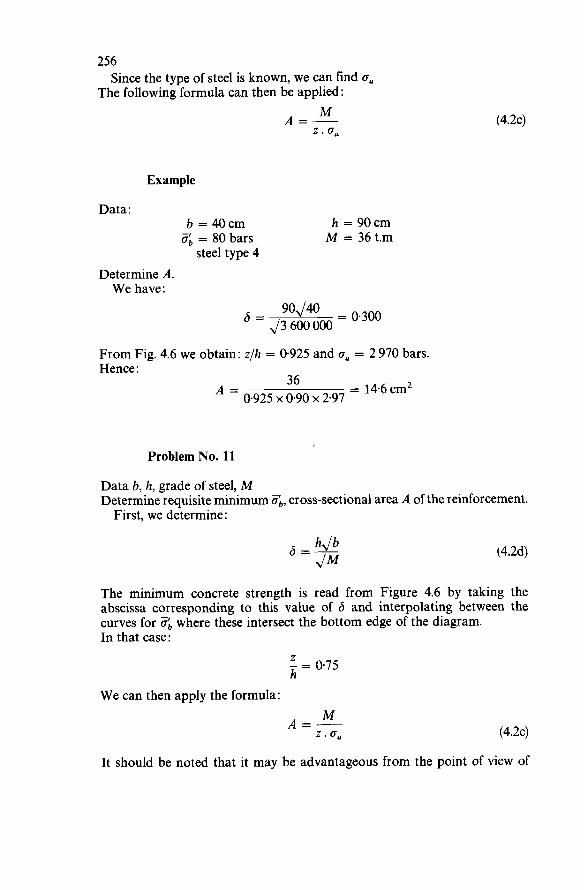
256
The following formula can then be applied : Since the type of steel is known, we can find o.
M A=- z . (4.2~)
Example
Data: b = 40cm h = 9 0 m 5: = 80 bars M = 36 t.m
steel type 4 Determine A. We have :
90 40 J = 0.300 = J 3 600000 From Fig. 4.6 we obtain: z/h = 0-925 and o, = 2 970 bars. Hence:
= 14.6cm2 36 0.925 x 0.90 x 2.97 A =
Problem No. 11
Data b, h, grade of steel, M Determine requisite minimum Zb, cross-sectional area A of the reinforcement. First, we determine:
(4.2d)
The minimum concrete strength is read from Figure 4.6 by taking the abscissa corresponding to this value of 6 and interpolating between the curves for ¿?íb where these intersect the bottom edge of the diagram. In that case :
Z - = 075 h
We can then apply the formula: M A=- z .o, (4.2~)
It should be noted that it may be advantageous from the point of view of
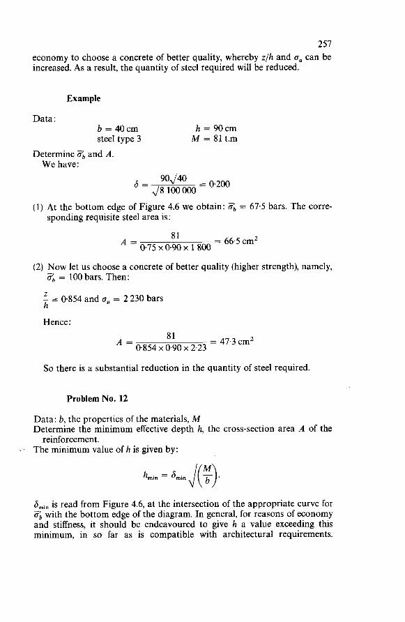
257 economy to choose a concrete of better quality, whereby zlh and o, can be increased. As a result, the quantity of steel required will be reduced.
Example
Data : b = 40cm steel type 3
Determine 8b and A. W e have :
h = 90cm M = 81 t.m
= 0.200 90,/40 I3 = 4 8 100000
(1) At the bottom edge of Figure 4.6 we obtain: O;, = 67.5 bars. The corre- sponding requisite steel area is:
= 66.5 cm2 81 0.75 x 0.90 x 1 800 A =
(2) Now let us choose a concrete of better quality (higher strength), namely, 6 = 100 bars. Then: z - = 0854 and on = 2 230 bars h
Hence:
= 47.3 cm2 81 0.854 x 0.90 x 2.23 A =
So there is a substantial reduction in the quantity of steel required.
Problem No. 12
Data: b, the properties of the materials, M Determine the minimum effective depth h, the cross-section area A of the
The minimum value of h is given by: reinforcement.
bmin is read from Figure 4.6, at the intersection of the appropriate curve for ab with the bottom edge of the diagram. In general, for reasons of economy and stiffness, it should be endeavoured to give h a value exceeding this minimum, in so far as is compatible with architectural requirements.
258 When h has thus been determined, the further treatment is as in problem No. 10.
Example
Data: b = 40cm steel type 4
Zb = 80 bars M = 36 t.m
Determine the requisite minimum effective depth h and A.
Hence : From Figure 4.6: hmi, = 0.184
3 600 O00 hmi, = 0,184 J( 4o ) = 55.2 cm
W e shall adopt a rather higher value, say: h = 75cm To this corresponds:
75 55.2 6 = 0.184~- = 0.250
On intersecting the perpendicular to this value of the abscissa with the curve o: = 80 in Figure 4.6 we obtain (as the abscissa, on the left-hand vertical scale) :
- = 0.886 and oa = 2 870 bars h
-
Z
Hence : = 18.9 cm2 36
0.886 x 0.75 x 2.87 A =
4.3.3 RECTANGULAR SECTION WITH COMPRESSIVE REINFORCEMENT
Having recourse to the use of compressive reinforcement to increase the bending moment that can be resisted by a beam whose cross-section and concrete quality are predetermined is always expensive in terms of the steel required. So it is, generally speaking, only in rather exceptional circumstances
that compressive steel will be used. In actual practice there are only two cases in which this is normally done: (a) if for operational or other compelling reasons it is quite impossible to
increase the cross-sectional dimensions of the member; (b) if the compressive zone has to be provided with reinforcement anyway,
for some other reason, e.g., if the member has to be designed for bending in alternate directions.
The problems dealt with in the previous case (no compressive reinforce- ment) will not be examined in detail for the member with compressive
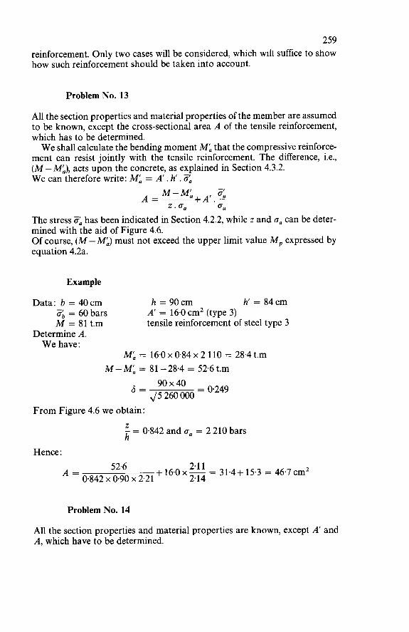
259 reinforcement. Only two cases will be considered, which will suffice to show how such reinforcement should be taken into account.
Problem No. 13
All the section properties and material properties of the member are assumed to be known, except the cross-sectional area A of the tensile reinforcement, which has to be determined. W e shall calculate the bending moment Ma that the compressive reinforce-
ment can resist jointly with the tensile reinforcement. The difference, i.e., (M - Má), acts upon the concrete, as explained in Section 4.3.2. W e can therefore write: Ma = A’. h . ZR
M-Má ZR A=- +A‘.- z . (Ta cll
The stress Za has been indicated in Section 4.2.2, while z and aa can be deter- mined with the aid of Figure 4.6. Of course, (M -Ma) must not exceed the upper limit value M, expressed by equation 4.2a.
Example
Data: b = 40cm h = 90cm h‘ = 84cm A’ = 16.0 cm2 (type 3) tensile reinforcement of steel type 3
Zb = 60 bars M = 81 t.m
Determine A. W e have :
Ma = M-Ma =
6 =
From Figure 4.6 we obtain:
16.0 x 0.84 x 2 110 = 81 -28.4 = 52.6 t.m 90x40 = 0.249
J 5 260 000
28.4 t.m
Z - = 0.842 and (T, = 2 210 bars h
Hence : 2.1 1 2.14 + 16.0 x - = 31.4+ 15.3 = 46.7 cm2 52.6
0.842 x 0.90 x 2.21 A =
Problem No. 14
All the section properties and material properties are known, except A’ and A, which have to be determined.
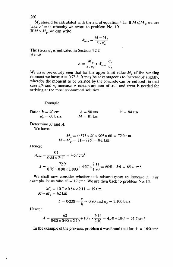
260
take A’ = O, whereby we revert to problem No. 10. If M > M,, we can write:
M, should be calculated with the aid of equation 4.2a. If M < M,, we Gan
M-M, A’. =- h . o:, min
The stress Oa is indicated in Section 4.2.2. Hence :
W e have previously seen that for the upper limit value M, of the bending moment we have: z = 0.75 h. It may be advantageous to increase A’ slightly, whereby the moment to be resisted by the concrete can be reduced; in that case z/h and oa increase. A certain amount of trial and error is needed for arriving at the most economical solution.
Example
Data: - b = 40cm
Determine A’ and A.
h = 90cm M = 81 t.m
h‘ = 84cm ob = 60 bars
W e have : M, = 0.375 x 40 x 90’ x 60 = 72.9 t.m
M - M, = 81 - 72.9 = 8.1 t.m Hence :
2.1 1 1.80 + 4.57 x - = 604 + 5.4 = 65.4 cm2 72.9
0.75 x 0.90 x 1.800 A =
W e shall now consider whether it is advantageous to increase A’. For example, let us take A’ = 17 cm2. W e are then back to problem No. 13.
Ma = 10.7 x 0.84 x 2.11 = 19 t.m M-M; = 62t.m
Z 6 = 0.228 + - = 0.80 and h = 2 100 bars Hence :
2.11 2.10 + 10.7 x- = 41.0+ 10.7 = 51.7 cm2 62
0.80 x 0.90 x 2.10 A =
In the example of the previous problem it was found that for A’ = 16.0 cm2
26 1 we obtain A = 46.7 cm’. The cost of the reinforcing steel will accordingly be proportional to the following figures: for A’ = ALin = 4.57 cmz :
A‘ = 10.7 cm’: A‘ = 16.0cm2:
4.57 + 65.4 = 69.97 10.7 + 51.7 = 62.4 16.0+46.7 = 62.7
The last two solutions are therefore practically equivalent from the point of view of economy.
4.3.4 T-SECTION
Determination Of The Effective Width Of The Compressive Flange
For freely supported T-beams with a single rib (web) or comprising a number of parallel ribs joined to the same top slab the effective width be-i.e., the flange width to be adopted in the structural calculations - can be determined with the aid of the graphs in Figures 4.7 and 4.8. These graphs are valid for uniform, triangular, parabolic or sinusoidal
load distribution and also for the case of a constant bending moment. O n the other hand, if the beam carries a locally concentrated load applied
to a zone of length a, the width to be taken into account on each side of the rib, at the corresponding section, should be reduced in relation to the values given by those graphs in the proportions stated in Table 4.3. For continuous T-beams and, in general, for T-beams in which changes
in the sign of the bending moment occur, the effective width should be calculated by adopting for 1 the distance between the points of zero bending moment.
Table 4.3 Table of values to be adopted for the flange width on each side of the rib, referred to 0.5 (be - bo)
1 b-bo __ a = O O < a < 0.ll O.ll<a
O 5 10
1 calculate by 0.6 1 linear 0.7 1 interpolation 0.9
In the vicinity of a ‘free’ support the effective width must not exceed the width bo plus twice the distance between the support and the section con- sidered. In the case of an asymmetrical beam, e.g., an edge beam, the effective width
be may be taken as the arithmetical mean of the values obtained by respectively considering the slab portion on each side of the rib in conjunction with its own mirror image. If the compressive flange is joined to the rib by haunches having a width
b, and a depth h,, then the actual width bo of the rib should be replaced by a
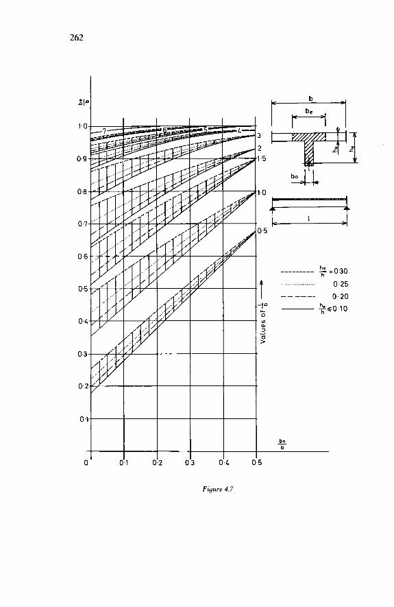
262
I 3 0-4
Figure 4.7
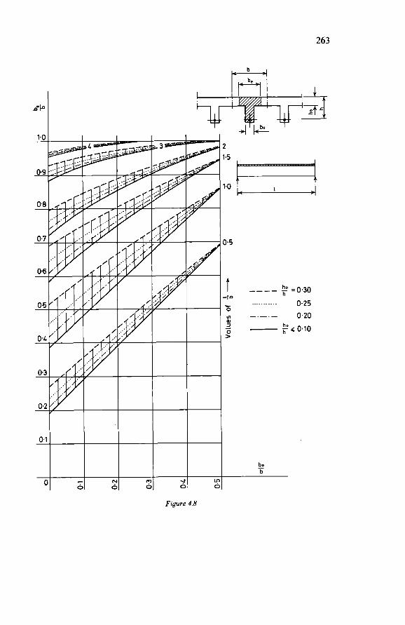
263
j ò O O O
t 1.0 ' I
_ _ _ _ 1. =0,30 - . . . . . . . . . . . . 0.25 yi 0.20
h -1-
O
al 3 ho
> ; - h (0.10
bo b -
Figure 4.8
264 fictitious width b, which should be taken as the smaller the two values: bo + 2bs and bo + 2hs.
Analysis Of A T-Section
To begin width, the given section should be compared with a rectangular section of the same depth and having a width equal to be. For this section it is possible, with the aid of Figure 4.6, to determine
y/h and therefore y. If y<ho, then the analysis will be an exact one, for the properties of the
given section and those of the assumed rectangular section are the same. If y > ho (which case occurs only if the compressive flange is thin), then the
analysis will have to be modified. In this latter case the compressive flange can be conceived as functioning
in the manner of compressive reinforcement, and the analysis can be carried out as though for a rectangular section of width bo and provided with com- pressive reinforcement. The bending moment that the flange can thus absorb jointly with the
tensile reinforcement is :
Mf = (be- bo)ho. O;, (4.4a)
The difference, i.e., (M - Mi), acts upon the rectangular beam of depth h and width bo as dealt with in Sections 4.3.2 and 4.3.3.
Problem No. 15
All the properties are assumed to be known, except the cross-sectional area A of the reinforcement, which has to be determined. If y < ho, the treatment is the same as for a rectangular section. If y > ho, then Mi should be calculated by means of equation 4.4a and then, considering the rectangular section bo . h, we can write:
Example 1 Data: be = 1.80m
ho = 12cm ob = 120 bars steel type 2
Equation 4.2d gives :
bo = 30cm h = 70cm M = 106 t.m -
Determine A.
(4.4b)
265 From Figure 4.6:
?! = 0.1 1 and hence: y = 7.7 cm h
We have: y<ho, so that it can indeed be treated as a rectangular section. From Figure 4.6 we furthermore obtain:
Z - = 0.945 and o, = 2 220 bars h
Hence :
= 72.3 cmz 106 0.945 x 0.70 x 2.22 A =
Example 2
The data are the same as in the previous example, but now 3, = 60 bars.
?! = 0.225 and hence: y = 15.7 cm h Since y exceeds ho, the calculation can permissibly be carried out in this way. Equation 4.4a gives :
M;= (180-30)~12~60~(70-6) = 69.1t.m
For 6 = 0.288 we now obtain from Figure 4.6:
The rectangular section bo. h must therefore absorb: 106 - 69.1 = 36.9 t.m
Hence, applying equation 4.2d:
From Figure 4.6 it appears that there is no solution, since the perpendicular erected at the abscissa 6 = 0.200 does not intersect the curve 3, = 60. It is therefore necessary to provide compressive reinforcement, whereby the bending moment that the concrete must absorb can be reduced. We shall so reduce this moment that, for example, y/h is equal to 0.40, which gives:
o,, = 2 220 bars. We find: 6 = 0.228 and, with the aid of equation 4.2f:
30 x 702 O 228 Ml = = 28.3 t.m
For these conditions the compressive reinforcement must absorb : 369-28.3 = 8.6 t.m
For example, reinforcement of steel type 3 will be installed at 7 c m from
266 the top edge of the section. For Za = 2 110 bars we obtain:
= 65cm2
2.11 60 +6.5 x -+ 150 x 12 x - 2.22 2 220
8.6 0.63 x 2.11
A’ =
= 77.5 cmz 28.3 0.80 x 0.70 x 2.22
and : A =
Problem No. 16
All the properties are assumed to be known, except h and A. Determine the requisite minimum depth, though bearing in mind that this is probably not the most economical solution and that it may be deficient from the point of view of stiffness.
If it can be assumed that h will exceed 2h0, the following method may be employed, which is very quick and gives a slightly over-estimated result very close to the precise value. Assume: y = ho; this gives:
M h0 be. ho. ob+? h = (4.4c)
and :
(4.4d)
If this calculation gives: hc2ho, the result is incorrect, for the upper limit moment M, will have been exceeded. If so, the section should be treated as a rectangular section of width be.
It should be noted that the effective width be itself sometimes depends on the ratio ho/h, so that a readjustment may be necessary after a first calculation.
Zb A = be. ho .- Ga
Example
Data: be = 1.80m bo = 30cm ho = 12cm A’ = O steel type 4
Ob = 120 bars M = 106 t.m
Determine hmi, and A. Equation 4.4~ gives :
10600000 12 18Ox12x 120 2 +- = 41+6 = 47cm h =
Check: h =- 2h0; the result is therefore acceptable. We thus obtain:
Y ho _-_- - - !.? = 0.256 + oa = 2 840 bars h 47
267 Equation 4.4d gives:
120 2 840 A = 180 x 12 x - = 91.2 cmz
4.4 C O M P O S I T E UNIAXIAL BENDING WITH COMPRESSION
4.4.1 ARBITRARY SECTION SYMMETRICALWITH RESPECT TO THE PLANE OF BENDING
Recapitulation Of Fundamental Assumptions
In addition to the fundamental assumptions on which the analysis for simple bending is based, the following is assumed: (a) If the depth x of the zone subject to compressive strain (shortening)
exceeds the effective depth h, the depth y of the rectangular compressive stress distribution diagram should be limited to :
X-075h .h if x>h = x-067h so that, when x tends to infinity (which corresponds to the case of concentric compression), y will not exceed h. (b) The bending moment M is calculated with respect to the level of the centroid of the tensile reinforcement.
Problem No. 17
Data: the section of the member, the reinforcement, the properties of the
Check the safety. materials, the direct force N’, the bending moment M = N’ . e.
Just as for simple bending (cf. problem No. i), the first condition is:
MSM, where:
M, = 0.75S.%+A’.K.h (cf. 4.lb) We can now write down:
M - A’. O:, . h ob
s, = -1 (cf. 4.1~)
Whence the level n-n and the depth y can be determined. With B and o, thus known, we obtain:
B . O:b+ A’. O:, - N’ =a
A . = min (4.5a)
If the numerator of this quotient is negative, the section is entirely in com- pression and the rectangular stress distribution diagram of the concrete
268 covers the whole depth of the section. In that case we must check that the force N is not too large. The compressive stress in the concrete is then:
M - A’. 3,. h S o;, = (4.5b)
and the total force that the given section is able to resist is equal to: M - A‘. Za . h’
S +A’. Za+A. Za (4%) Nmax = B,.
where B, denotes the total cross-sectional area of the member. It remains to be checked that N’ < NLax.
If this condition is not satisfied, it is necessary to consider a change in the sign of the bending moment: calculate the eccentricity of N‘ with respect to the reinforcement A’, which then functions as the tensile (or the least compressed) reinforcement; the depth y should then be reckoned from the edge closest to the reinforcement A.
Example (a)
Data: the section shown in Figure 4.4a. A’ = 1.13 cm2 (type 3) Zb = 90 bars M = 1.85 t.m
Analyse the member.
A = 8.6 cm’ (type 1) N = 3.1 t
W e have :
Hence : M, = (10 667 x 67.5)+(1.13 x 2 110 x 32.5) = 7.97 t.m
The first condition is satisfied. Furthermore :
185 000-(1.13 x 2 110 x 32.5) = 190 cm3 90 s, = From Figure 4.5 we obtain: y = 8.2 c m
For
- 8’2 - 0.205 we obtain from Figures 4.3 h=z- E, = 053% and o, = 1 335 bars
W e also have:
and 4.1 :
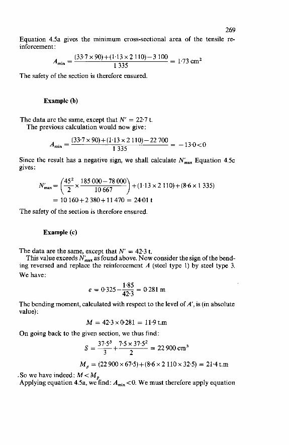
269 Equation 4.5a gives the minimum cross-sectional area of the tensile re- inforcement :
(33.7~90)+(1.13~2110)-3 100 = 1.73cm2 A . = 1335 min
The safety of the section is therefore ensured.
Example (b)
The data are the same, except that N‘ = 22.7 t. The previous calculation would now give:
(33.7 x 90)+ (1.13 x 2 110) - 22 700 1335 = -13’0t0 Amin =
Since the result has a negative sign, we shall calculate Nmax Equation 4.5~ gives :
452 185 Om) +(i43 x 2 110)+(8.6 x i 335) 10 667 = 10 160+2 380+ 11 470 = 24.01 t
The safety of the section is therefore ensured.
Example (c)
The data are the same, except that N = 42.3 t. This value exceeds NmaX as found above. N o w consider the sign of the bend-
ing reversed and replace the reinforcement A (steel type 1) by steel type 3. We have :
1.85 e = 0.325-- = 0.281 m 42.3 The bending moment, calculated with respect to the level of A’, is (in absolute value) :
M = 42.3 x 0.281 = 11.9 t.m O n going back to the given section, we thus find:
37.53 7.5 x 37.5’ = 22 9oo cm3 2 s=- + 3
M, = (22 900 x 67.5) +(8.6 x 2 110 x 32.5) = 21.4 t.m . So we have indeed: M < M, Applying equation 4.5a, we find: Ami,, <O. We must therefore apply equation
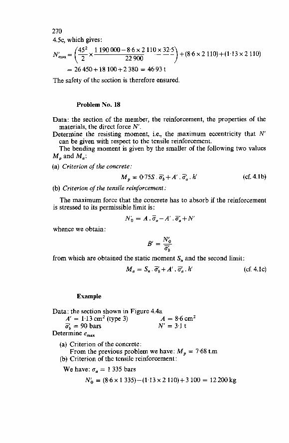
270 4 . 5 ~ ~ which gives : ) +(8,6x 2 110)+(1.13 x 2 110) 452 1 190 O00 - 8.6 x 2 110 x 32.5
22 900 Nmax = (2 x = 26 450+ 18 100+2 380 = 46.93 t
The safety of the section is therefore ensured.
Problem No. 18
Data: the section of the member, the reinforcement, the properties of the materials, the direct force N’.
Determine the resisting moment, i.e., the maximum eccentricity that N can be given with respect to the tensile reinforcement. The bending moment is given by the smaller of the following two values
M, and Ma: (a) Criterion of the concrete:
M, = 0.75s. Zb+A’. Za. h (cf. 4.lb)
(b) Criterion of the tensile reinforcement:
is stressed to its permissible limit is: The maximum force that the concrete has to absorb if the reinforcement
Nó = A.Za-A’.Za+N’ whence we obtain:
from which are obtained the static moment S, and the second limit: Ma = S,.Zb+A’.Za.h‘ (cf. 4. lc)
Example
Data: the section shown in Figure 4.4a A’ = 1.13 cm2 (type 3) 3, = 90 bars
A = 8.6cm2 N‘ = 3.1 t
Determine emax (a) Criterion of the concrete:
(b) Criterion of the tensile reinforcement: From the previous problem we have: M, = 7.68 t.m
We have: oa = 1335 bars Nó = (8’6x1 335)-(1.13~2110)+3 100 = 12200kg
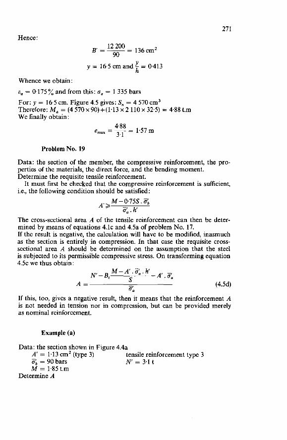
27 1 Hence:
- 136cm’ 12 200 90
BI=--
Y h y = 16.5 cm and - = 0.413
Whence we obtain: E, = 0.175% and from this: o, = 1 335 bars For: y = 16.5 cm. Figure 4.5 gives: S, = 4 570 cm3 Therefore: M, = (4 570 x 90)+(1.13 x 2 110 x 32.5) = 4.88 t.m We finally obtain:
Problem No. 19
Data: the section of the member, the compressive reinforcement, the pro- perties of the materials, the direct force, and the bending moment. Determine the requisite tensile reinforcement.
i.e., the following condition should be satisfied : It must first be checked that the compressive reinforcement is sufficient,
M-075S.Zb Ata 3, . h The cross-sectional area A of the tensile reinforcement can then be deter- mined by means of equations 4.lc and 4.5a of problem No. 17. If the result is negative, the calculation will have to be modified, inasmuch as the section is entirely in compression. In that case the requisite cross- sectional area A should be determined on the assumption that the steel is subjected to its permissible compressive stress. On transforming equation 4.5~ we thus obtain:
M- A’. 3, . h S -A‘.3,
(4.5d)
If this, too, gives a negative result, then it means that the reinforcement A is not needed in tension nor in compression, but can be provided merely as nominal reinforcement.
N-B, A =
3,
Example (a)
Data: the section shown in Figure 4.4a A’ = 1.13 cm2 (type 3)
M = 1.85 t.m
tensile reinforcement type 3 Ob = 90 bars N = 3.1 t
Determine A
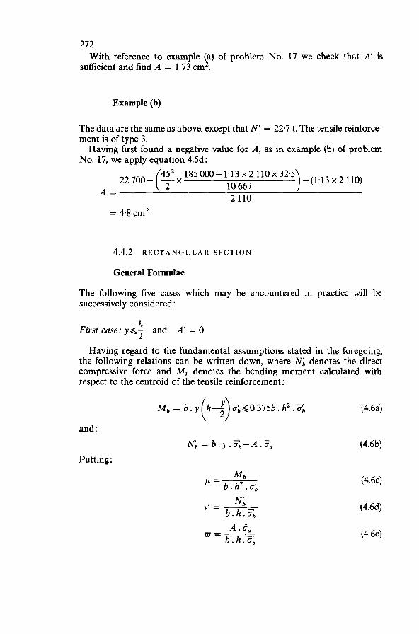
272
sufficient and find A = 1.73 cm2. With reference to example (a) of problem No. 17 we check that A’ is
Example (b)
The data are the same as above, except that N‘ = 22.7 t. The tensile reinforce- ment is of type 3. Having first found a negative value for A, as in example (b) of problem
No. 17, we apply equation 4.5d:
-(1’13 x 2 110) 185 000- 1.13 x 2 110 x 32.5 10 667 2 110 A =
= 4.8 cm2
4.4.2 R E c T A NG U L A R s E c TI ON
General Formulae
The following five cases which may be encountered in practice will be successively considered :
h First case: y,<- and A‘ = O 2 Having regard to the fundamental assumptions stated in the foregoing,
the following relations can be written down, where N b denotes the direct compressive force and M b denotes the bending moment calculated with respect to the centroid of the tensile reinforcement :
(4.6a)
and :
Putting :
NIb = b.y.Zb-A.Ea (4.6b)
(4.6~)
(4.6d)
(4.6e)
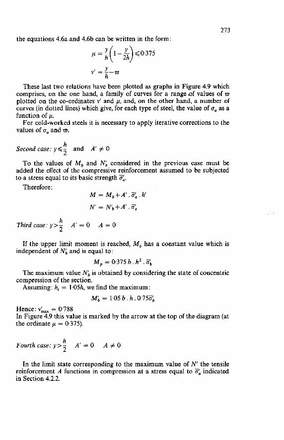
273 the equations 4.6a and 4.6b can be written in the form:
Y y’ = --m h
These last two relations have been plotted as graphs in Figure 4.9 which comprises, on the one hand, a family of curves for a range of values of m plotted on the co-ordinates v’ and p, and, on the other hand, a number of curves (in dotted lines) which give, for each type of steel, the value of oa as a function of p. For cold-worked steels it is necessary to apply iterative corrections to the
values of oa and m.
h Second case: y < - and A’ # O 2 To the values of M, and N, considered in the previous case must be
added the effect of the compressive reinforcement assumed to be subjected to a stress equal to its basic strength ZA.
Therefore : M = Mb+A’.za.h‘ N’ = N b - k . 4 ’ .
h 2 Third case: y>- A‘ = O A = O
If the upper limit moment is reached, M, has a constant value which is independent of N b and is equal to:
M, = 0.375 b. h2. 6 The maximum value N, is obtained by considering the state of concentric
Assuming: h, = 1.05h, we find the maximum: compression of the section.
M g = 1.05 b. h. 0.750, Hence: vLax = 0.788 In Figure 4.9 this value is marked by the arrow at the top of the diagram (at the ordinate p = 0.375).
h 2 Fourth case: y>- A‘ = O A # O
In the limit state corresponding to the maximum value of N’ the tensile reinforcement A functions in compression at a stress equal to Oa indicated in Section 4.2.2.
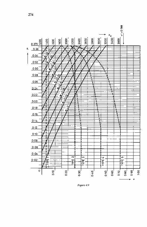
274
a
Figure 4.9
275 To the value of vkax we can therefore add the following:
A . Üa WC = ~ b.h.3,
h Fgth case: y>- 2 A’ # O Just as in the second case we can write down for the limit state:
M = M,+A’.$,.h N = Nb+A’.Üa
Problem No. 20
Data: b, h, h, A’, A, the properties of the materials, N‘ and M = N‘ . e Check the safety of the member. Calculate :
Mb = M-A‘.ZL.h Nb = N-A’.Ü,
Equations 4.6~ and 4.6d give p and d. The values w and oa are obtained from Figure 4.9. The requisite minimum steel area can now be determined:
w. b. h . Üb A . = min Da
The actual steel provided should be at least equal to this, i.e., A 2 Ami,
Example
Data b = 5Ocm h = 65cm h’ = 60cm ob = 120 bars N = 74.5 t - M = 80.3 t.m A’ = 10 cm2 (type 3) A = 25.5 cm2 (type 3)
Analyse the member. W e can successively write down:
M, = 8030000-(10x2110x60) = 6764000kg.cm N b = 74 500- (10 x 2 110) = 53 400 kg
= 0.266 6 764 O00 = 50 ~ 6 5 ~ x 120
= 0.136 53 400 50 x 65 x 120
v’ =
Figure 4.9 gives: w = 0.180 and oa = 2 210 bars
276 Hence :
0.180 x 50 x 65 x 120 = 31.8 cm2 A . = 2 210 min
The given cross-sectional area of tensile reinforcement is therefore insufficient.
Problem No. 21
Data: b, h, h, A’, A, the properties of the materials, N’ Determine the resisting moment, i.e., the maximum eccentricity of N with respect to the tensile reinforcement. Calculate : Yb = N’ - A’ . ¿fa
Equations 4.6d and 4.6e give v’ and m. Figure 4.9 provides the maximum value of ,u and the corresponding value of o, which may necessitate some correction of zu. Finally: M,, = ,u.6.h2.Zb+A’.Z,.h’
Example (a)
b = 50cm Data:
h = 65cm h’ = 60cm N‘ = 74.5 t -
o; = 120 bars A‘ = 10 cm2 (type 3) A = 25.5 cm2 (type 3)
Determine M,,,. We can successively write down:
N b = 74 500-(10 x 2 110) = 53 400 kg v‘ = 53400 = 0.136
50 x 65 x 120 25.5 x 2 250 = o.147 50 x 65 x 120 Adopting: o, = 2 250 bars, we obtain: ar =
Figure 4.9 gives: p = 0.242 and o, = 2 250 bars The value adopted for o, was therefore a suitable one. Hence: M,,, = (0.242 x 50 x 65’ x 120) = 73.9 t.m and therefore:
= 0.99m 73.9 emax =- 74.5
Example (b)
The data are the same as before, except that N’ = 297 t.
Nb = 297000-(10~2110) = 275900kg In this case we have :
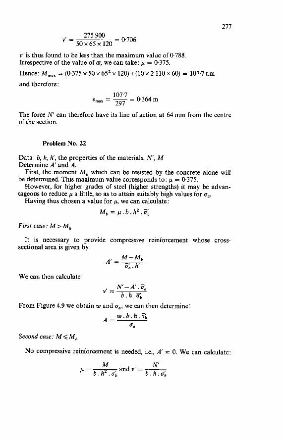
277
= 0.706 275 900 50 x 65 x 120
VI =
Y’ is thus found to be less than the maximum value of 0788. Irrespective of the value of m, we can take: p = 0.375. Hence: M,,, = (0.375 x 50 x 652 x 120)+(10 x 2 110 x 60) = 107.7 t.m and therefore:
- 0.364m emax = - - 107.7 297
The force N can therefore have its line of action at 64 mm from the centre of the section.
Problem No. 22
Data: b, h, h’, the properties of the materials, N, M Determine A’ and A.
be determined. This maximum value corresponds to: p = 0.375.
tageous to reduce p a little, so as to attain suitably high values for o,.
First, the moment M, which can be resisted by the concrete alone will
However, for higher grades of steel (higher strengths) it may be advan-
Having thus chosen a value for p, we can calculate: M, = p . b . h 2 . <
First case: M > M,
It is necessary to provide compressive reinforcement whose cross- sectional area is given by:
W e can then calculate: N-A.3, v’ = b.h.3,
From Figure 4.9 we obtain m and o,; we can then determine: m . b. h. 3,
0. A =
Second case: M < M, No compressive reinforcement is needed, i.e., A‘ = O. We can calculate:
N -, and Y‘ = ~ ’= b.h2.0, b . h . Z b
M
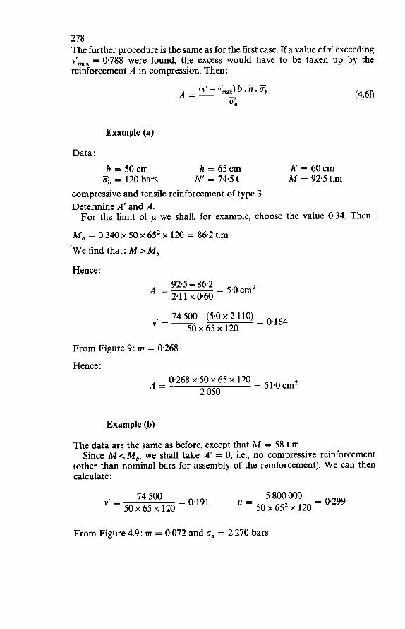
278 The further procedure is the same as for the first case. If a value of v' exceeding v',,, = 0.788 were found, the excess would have to be taken up by the reinforcement A in compression. Then :
Example (a)
Data: b = 50cm h = 65cm h'= 60cm ob = 120 bars N' = 74.5 t M = 925 t.m
compressive and tensile reinforcement of type 3 Determine A' and A. For the limit of p we shall, for example, choose the value 0.34. Then:
Mb = 0.340 X 50 X 652 X 120 = 86.2 t.m We find that: M > M b
Hence :
= 5.0cm2 92.5 - 86.2 A' = 2.11 x 0.60
74 500-(5.0 x 2 110) = o,164 v' = 50 x 65 x 120
From Figure 9: w = 0268 Hence :
0.268 x 50 x 65 x 120 = 51.0 cm2 2 050 A =
Example (b).
The data are the same as before, except that M = 58 t.m Since M<Mb, we shall take A' = O, i.e., no compressive reinforcement
(other than nominal bars for assembly of the reinforcement). We can then calculate :
= 0.299 5 800 O00 74500 = 0.191 = 50 x 652 x 120 y' =
50 x 65 x 120
From Figure 4.9: m = 0.072 and on = 2 270 bars
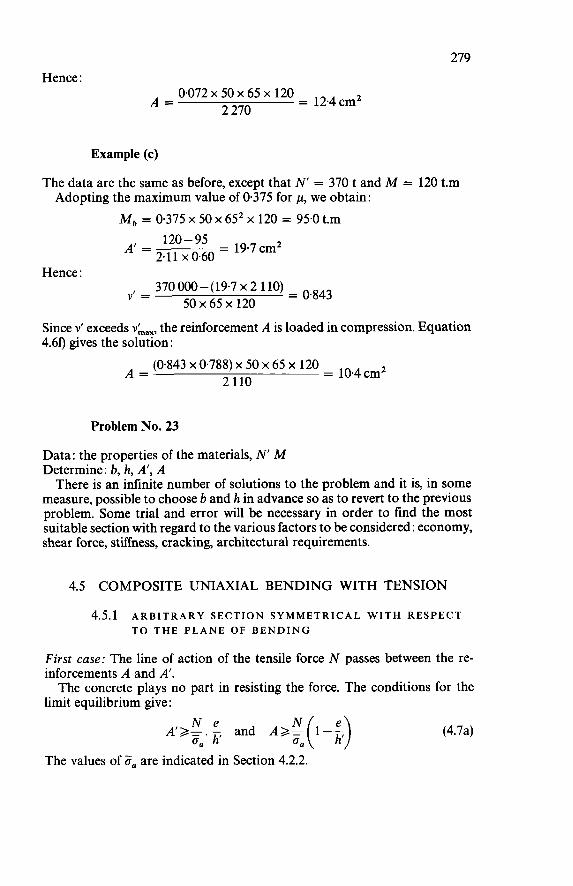
279 Hence :
0.072 x 50 x 65 x 120 = 12.4 cm2 2 270 A =
Example (c)
The data are the same as before, except that N' = 370 t and M = 120 t.m Adopting the maximum value of 0.375 for p, we obtain:
M, = 0.375 x 50 x 65' x 120 = 95.0 t.m
Hence : 370 000-(19.7 x 2 110) = o.843
y' = 50 x 65 x 120
Since v' exceeds 4.60 gives the solution:
the reinforcement A is loaded in compression. Equation
= 10.4cm2 (0843 x 0.788) x 50 x 65 x 120 2 110 A =
Problem No. 23
Data: the properties of the materials, N M Determine: b, h, A', A There is an infinite number of solutions to the problem and it is, in some
measure, possible to choose b and h in advance so as to revert to the previous problem. Some trial and error will be necessary in order to find the most suitable section with regard to the various factors to be considered: economy, shear force, stiffness, cracking, architectural requirements.
4.5 COMPOSITE UNIAXIAL BENDING WITH TENSION
4.5.1 ARBITRARY SECTION SYMMETRICAL WITH RESPECT TO THE PLANE OF BENDING
First case: The line of action of the tensile force N passes between the re- inforcements A and A'. The concrete plays no part in resisting the force. The conditions for the
limit equilibrium give :
(4.7a)
The values of 5, are indicated in Section 4.2.2.
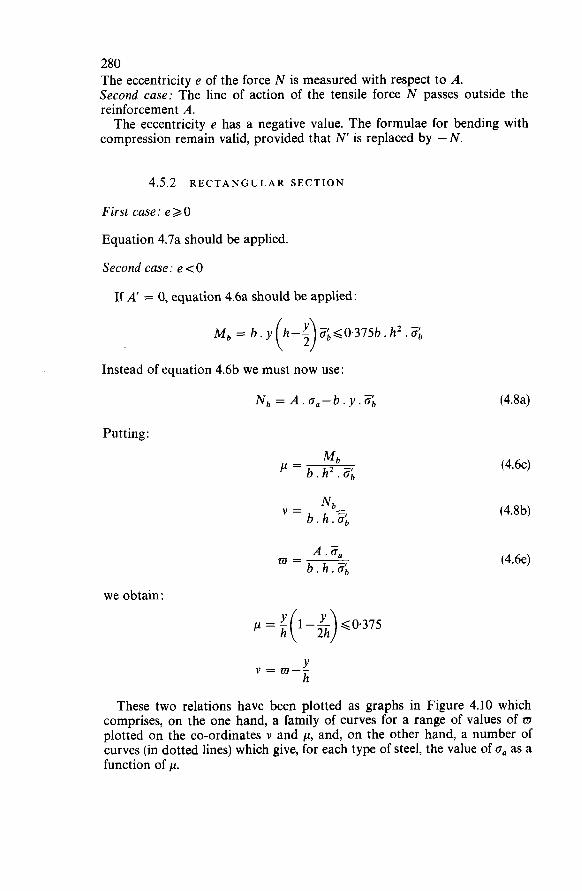
280 The eccentricity e of the force N is measured with respect to A. Second case: The line of action of the tensile force N passes outside the reinforcement A. The eccentricity e has a negative value. The formulae for bending with
compression remain valid, provided that N is replaced by -N.
4.5.2 RECTANGULAR SECTION
First case : e 2 O
Equation 4.7a should be applied.
Second case: e <O
If A' = O, equation 4.6a should be applied:
Instead of equation 4.6b we must now use:
Putting:
we obtain:
/.i - 1-- G0.375 h( :h)
(4.8a)
(4.6~)
(4.8b)
(4.6e)
These two relations have been plotted as graphs in Figure 4.10 which comprises, on the one hand, a family of curves for a range of values of EI plotted on the co-ordinates v and /.i, and, on the other hand, a number of curves (in dotted lines) which give, for each type of steel, the value of oa as a function of /.i.
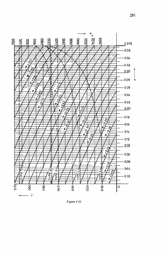
28 1
- v
Figure 4.10
282 If A’ is not zero, the following formulae should be applied:
M=Mb+A‘.3a.h‘ and
N = Nb-A’.3*
Problem No. 24
Data: b, h, h’, A’, A, the properties of the materials, N, M = - N . e (e<O). Check the safety of the member.
Calculate :
M, = M-A’.Za.h and :
N b = N+A’. 3,
Equations 4.6~ and 4.8b give p and v. The values of m and oa are obtained from Figure 4.10. The requisite steel area can then be calculated:
w. b. h. 3, A . = min oa
Example
Data: b = 50cm h = 65cm 3, = 120 bars A’ = 10cm2 (type 3)
N = 594 t
Analyse the member. W e can successively write down:
h’= 60cm M 435 t.m
M, = 4350000-(10x2110x60) = 3084000kg.cm
N, = 59400+(10~2110) = 80500kg
= 0.122 3 084 O00 = 50 x 652 x 120
= 0.207 80 500 ’= 50x65~120
Figure 4.10 gives: m = 0.34 and oa = 2 420 bars
283 Hence :
0.34 x 50 x 65 x 120 = 54.8 cm2 A . = min 2 420 The safety of the section is therefore ensured.
Problem No. 25
Data: b, h, h', the properties of the materials, N, M. Determine A' and A.
crete alone. This maximum value corresponds to : First, we shall determine the moment M, that can be resisted by the con-
p = 0.375. However, for higher grades of steel (higher strengths) it may be advantageous to reduce p a little, so as to attain suitably high values for on. Having thus chosen a value for p, we can calculate:
First case : M > M,
area is given by:
M b = p . b . h 2 . &
It is necessary to provide compressive reinforcement whose cross-sectional
We can then calculate: N+A'.3, b.h.3, v =
From Fig. 10 we obtain m and a,; we can then determine: m. b. h. ab A =
O n
Second case: M < M, No compressive reinforcement is needed, i.e., A' = O. We can calculate:
N and v = ~
b . h . 3 , M
= b. h2 . ob The further procedure is the same as for the first case.
Example
Data: b = 50cm 3, = 120 bars
Determine A' and A. Choose: ,LL = 0.300
h = 65cm N = 59.4 t
h' = 60cm M = 43.5 t.m
284 We thus obtain: M, = 0.300 x 50 x 652 x 120 = 76.0 t.m Therefore: M <Mb, so that we can take: A’ = O We can now calculate:
= 0.152 95 400 50 x 65 x 120 v =
4 350 000 = o. 172 !-¿ =50 x 65’ x 120
Figure 4.10 gives: w = 0.342 and o. = 2 340 bars Hence :
0.342 x 50 x 65 x 120 = 57,0 ,,’ 2 340 A =
5
ANALYSIS OF TENSILE AND FLEXURAL CRACKING
5.1 PRELIMINARY REMARKS
A tensile crack will appear in a structural member subjected to tensile stress when, at a given point, the strain of the member exceeds the maximum ulti- mate strain and when, associated with this, the stress exceeds the tensile strength. In an initially uncracked concrete member without reinforcement these phenomena produce failure which concides with the development of the first crack, perpendicularly to the direction of the tensile force. This failure is not preceded by any warning signs ; it occurs suddenly. Precise measurements show that the strains which occur in a test specimen of this kind remain substantially proportional to the tensile stresses almost up to failure. The slight departure from proportionality that occurs just before failure can be neglected, so that failure can be said to occur practically in the elastic range of behaviour, without any plastification of the concrete in ten- sion being involved. In the case of concrete the origin of the cracks is attributable to one of the
following factors :
Action of shrinkage of the concrete, if that action encounters restraint either as a result of structural arrangements (case where the member is unable to expand freely, e.g., if it is anchored at its ends) or as a result of bond of the reinforcement (case where the member is reinforced and the development of tension in the concrete is accompanied by the development of compression in the steel). Action of temperature variation, because of the difference between the co- efficients of thermal expansion of concrete and steel respectively. However, if the .variation in temperature does not exceed f2O0C, its action can be re- garded negligible in the development of cracking. Action of an external tensile force applied to the ends of the member.
285
286 5.2 ANALYSIS OF CRACKING IN REINFORCED CONCRETE
5.2.1 PURPOSE OF ANALYSIS OF CRACKING
The essential purpose of the theories of cracking of reinforced concrete is to be able to predict - with due regard to the action of shrinkage and external forces - the development of the distribution and widths of the cracks in the various members of a structure. In a more general way they should enable us to determine and verify, with a degree of accuracy compatible with the random character of the phenomenon, the limit state of cracking of those structural members. This limit state will itself be conditioned by the nature of the structure, its environmental conditions, the possible risk of corrosion of the reinforcement, and the need to safeguard the durability of the structure. In their present state of development the theories of cracking of reinforced
concrete aim at calculating the distribution and the widths of the flexural and tensile cracks, which are assumed to be perpendicular to the direction of the reinforcement. This is evidently a limited domain, since it excludes more particularly
the shear cracks, the theoretical calculation of which, if properly carried out, would be of extreme complexity. In fact, such a calculation would have to take account not only of the development of the ‘diagonal’ stresses and of the fundamental criteria of failure of concrete, but also of the type of reinforce- ment and the other structural arrangements which decisively affect the development of the phenomenon. Also, the theories are unable to take the longitudinal cracks, extending
parallel to the reinforcement, into consideration, although such cracks are very dangerous from the point of view of corrosion of the steel. The forma- tion and spreading of these cracks depend essentially upon the density of the concrete and the cover to the bars, particularly along the edges of the members, and are therefore not amenable to systematic theoretical calculation.
5.2.2 BASIC ASSUMPTIONS FOR THE CALCULATION OF CRACKING
These basic assumptions concern : (a) the reference definition of the crack width; (b) the bond stress distribution along the longitudinal reinforcement; (c) the effect of the presence of transverse reinforcement; (d) the estimation of the tensile strength of the concrete; (e) ignoring the effect of temperature variations.
Reference Definition Of Crack Width
A crack generally follows a sinuous path. For defining and measuring the width of the crack it is therefore difficult to refer to a precise direction.
287 The only reasonable assumptions consist in considering the width of a
crack parallel to the main reinforcing bars, at the level of their centroid, at the external surface of the concrete. These arbitrary assumptions are, however, each a source of inaccuracy
which accentuates the random character of the phenomenon. These inaccuracies are confirmed by many tests which have clearly re-
vealed the great variations that may occur in the crack widths, both at the external surface and in the interior of the concrete surrounding the re- inforcement.
Distribution Of The Bond Stresses Between Concrete And Steel
The relationship z(x) which governs the distribution of the bond stresses along the reinforcement is of fundamental importance in the development of the theories of cracking of reinforced concrete. In actual practice, however, this importance is more apparent than real, for the work of the Comité Européen du Béton (C.E.B.) has shown that, while the theories of cracking generally differ from one another in having very different basic hypotheses, they can, by virtue of their mode of development, be brought into line with one another in a single theory and yield practically equivalent results con- forming to the usual experimental measurements. This does not make it any less essential to adopt a hypothesis for the bond
stress distribution. The various ‘laws’ or relationships governing the phenomenon, as evolved by theoretical investigators, can for the most part be classified into two principal types : the relationships based on sinusoidal variation (including Professor Saliger’s theory) and those based on uniform friction (including Mr. L. P. Brice’s theory). Other investigators have en- visaged, more or less implicitly, a linear variation (including Professor Wästlund’s theory). Others, again, have adopted formulae of experimental origin, without theoretical development, and have thus been able to bypass the need for making basic assumptions as to the stress distribution. For practical purposes, in the case of members subjected to concentric
tension or simple bending, the tests appear to show that (at any rate, in the mid-span zones of such members):
(a) if the steel stress remains below about three-quarters of the elastic limit, the bond stress distribution can be considered to be sinusoidal;
(b) if the steel stress exceeds about three-quarters of the elastic limit, the bond stress distribution can be taken gradually to approximate to a relationship characterised by constant friction.
Effect Of Transverse Reinforcement
\
The presence of transverse reinforcement undeniably forms points of dis- continuity in the bond between the concrete and the steel because, for one thing, it is equivalent to a local reduction of the section and particularly to a
288 lowering of the quality of the concrete cover and, furthermore, it presents an obstacle to the displacement of the reinforcing bar in relation to the concrete. This local impairment therefore very considerably increases the probability that a crack will form.
Estimation Of The Tensile Strength Of The Concrete
It is known that the tensile strength of concrete is highly sensitive to the slightest local flaw in manufacture and that the minimum value o. of this strength at a given point of the structure determines the development of the first crack. The progressive development of cracking is a function of other local flaws
of the concrete in tension, for respective strengths (oo +Aloa), (oo + Azoo), . . . (oo + Anoo), where:
OtA,oo < Azoo < . . . < Anoo However, since the actual distribution of the local tensile strength values
of concrete is of an entirely random character, the only possible hypothesis for the calculation of cracking consists in considering, over the whole length of the member (or even throughout the entire structure), a uniform and minimum value of the tensile strength, defined more or less arbitrarily in terms of results yielded by tests on standard specimens.
Ignoring The Effect Of Temperature Variations
This effect can be neglected in the calculation of cracking because, for temperature variations not exceeding f 20°C, it corresponds practically to the error in estimating the shrinkage of the concrete.
5.2.3 CALCULATION OF CRACKING IN UNDER-REINFORCED MEMBERS
Range Of Validity
The members concerned are 'under-reinforced in the sense that the rein- forcement, because of its percentage being too low, is unable, when the first crack appears, suitably to resist the force that previously was resisted by the concrete in tension. This is more particularly the case with members in which the reinforcement
percentage is too low to enable them to withstand the action of the shrinkage of the concrete, even in the absence of any external tensile force. Such members crack systematically merely as a result of shrinkage, without the reinforcement being able to ensure effective transmission of the forces. Reinforcement present in so low a percentage will reach the range of plastic strain as soon as the first shrinkage crack is formed.
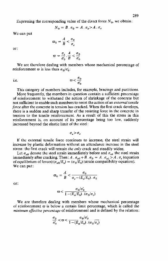
289 Expressing the corresponding value of the direct force No, we obtain:
No = B.oo = A.o,>A.oe W e can put
or :
W e are therefore dealing with members whose mechanical percentage of reinforcement w is less than oo/oó:
i.e.
This category of members includes, for example, bracings and partitions. More frequently, the members in question contain a sufficient percentage
of reinforcement to withstand the action of shrinkage of the concrete but not sufficient to enable such members to resist the action of an external tensile force after the concrete in tension has cracked. When the first crack develops, there is a sudden and sharp transfer of the resisting force in the concrete in tension to the tensile reinforcement. As a result of this the stress in this reinforcement is, on account of its percentage being too low, suddenly increased beyond the elastic limit of the steel:
oa’oe If the external tensile force continues to increase, the steel strain will
increase by plastic deformation without an attendance increase in the steel stress: the first crack will remain the only crack and steadily widen. Let oaO denote the steel strain immediately before and oal the steel strain
immediately after cracking. Then: A . oao + B . o. = A . oal > A . oe (equation of equilibrium of forces) (oao/&) = (oo/Eb) (strain compatibility equation). W e can put:
or:
W e are therefore dealing with members whose mechanical percentage of reinforcement w is below a certain limit percentage, which is called the minimum effective percentage of reinforcement and is defined by the relation:
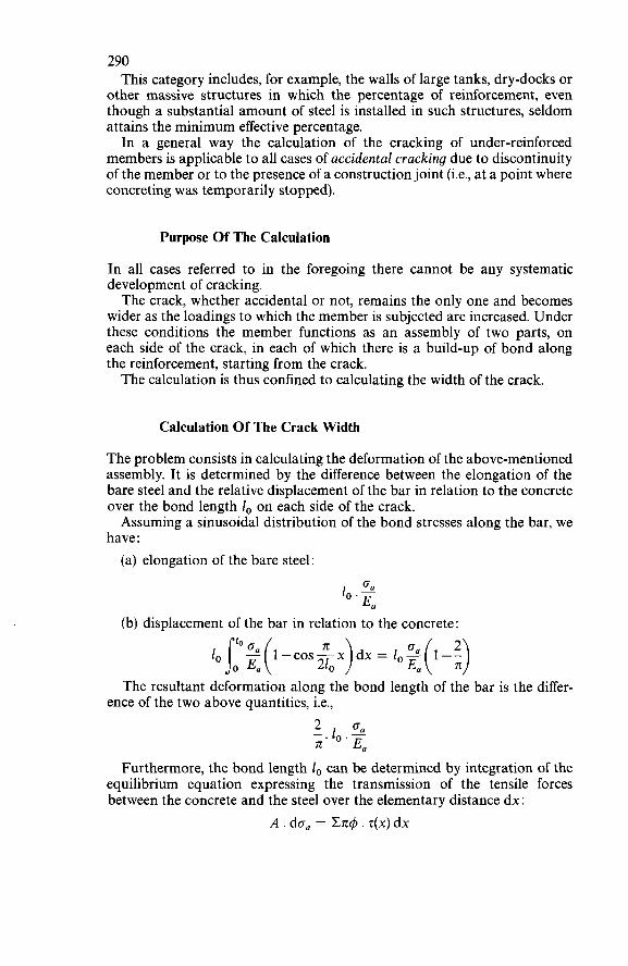
290 This category includes, for example, the walls of large tanks, dry-docks or
other massive structures in which the percentage of reinforcement, even though a substantial amount of steel is installed in such structures, seldom attains the minimum effective percentage. In a general way the calculation of the cracking of under-reinforced
members is applicable to all cases of accidental cracking due to discontinuity of the member or to the presence of a construction joint (i.e., at a point where concreting was temporarily stopped).
Purpose Of The Calculation
In all cases referred to in the foregoing there cannot be any systematic development of cracking. The crack, whether accidental or not, remains the only one and becomes
wider as the loadings to which the member is subjected are increased. Under these conditions the member functions as an assembly of two parts, on each side of the crack, in each of which there is a build-up of bond along the reinforcement, starting from the crack. The calculation is thus confined to calculating the width of the crack.
Calculation Of The Crack Width
The problem consists in calculating the deformation of the above-mentioned assembly. It is determined by the difference between the elongation of the bare steel and the relative displacement of the bar in relation to the concrete over the bond length 1, on each side of the crack. Assuming a sinusoidal distribution of the bond stresses along the bar, we
have : (a) elongation of the bare steel:
O R 1, .- E R
(b) displacement of the bar in relation to the concrete:
1, j:2 (1 -cos$,> dx = 1, :( 1 -:) The resultant deformation along the bond length of the bar is the differ-
ence of the two above quantities, i.e., -.lo.- 2 G R = E R
Furthermore, the bond length i, can be determined by integration of the equilibrium equation expressing the transmission of the tensile forces between the concrete and the steel over the elementary distance dx:
A . do, = &d . Z(X) dx
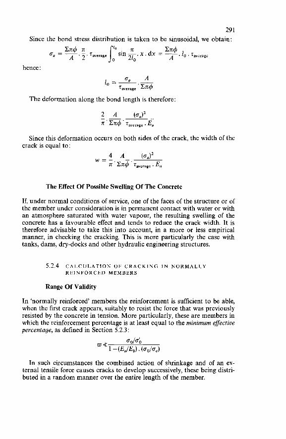
29 1 Since the bond stress distribution is taken to be sinusoidal, we obtain:
En4 x . dx = - . 1, . 7average A o, = -
hence :
lo=- On - A average '
The deformation along the bond length is therefore
Since this deformation occurs on both sides of the crack, the width of the crack is equal to:
4 A (0,)'
71' Cn4' raverage ' E a w = - -
The Effect Of Possible Swelling Of The Concrete
If, under normal conditions of service, one of the faces of the structure or of the member under consideration is in permanent contact with water or with an atmosphere saturated with water vapour, the resulting swelling of the concrete has a favourable effect and tends to reduce the crack width. It is therefore advisable to take this into account, in a more or less empirical manner, in checking the cracking. This is more particularly the case with tanks, dams, dry-docks and other hydraulic engineering structures.
5.2.4 CALCULATION OF CRACKING I N NORMALLY REINFORCED MEMBERS
Range Of Validity
In 'normally reinforced' members the reinforcement is sufficient to be able, when the first crack appears, suitably to resist the force that was previously resisted by the concrete in tension. More particularly, these are members in which the reinforcement percentage is at least equal to the minimum effective percentage, as defined in Section 5.2.3 :
In such circumstances the combined action of shrinkage and of an ex- ternal tensile force causes cracks to develop successively, these being distri- buted in a random manner over the entire length of the member.
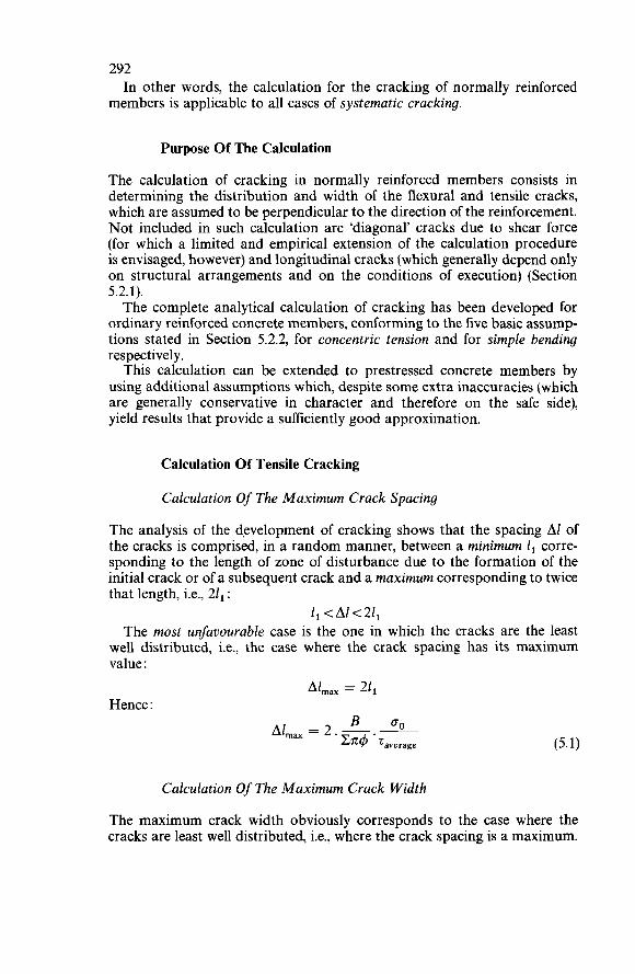
292
members is applicable to all cases of systematic cracking. In other words, the calculation for the cracking of normally reinforced
Purpose Of The Calculation
The calculation of cracking in normally reinforced members consists in determining the distribution and width of the flexural and tensile cracks, which are assumed to be perpendicular to the direction of the reinforcement. Not included in such calculation are 'diagonal' cracks due to shear force (for which a limited and empirical extension of the calculation procedure is envisaged, however) and longitudinal cracks (which generally depend only on structural arrangements and on the conditions of execution) (Section 5.2.1). The complete analytical calculation of cracking has been developed for
ordinary reinforced concrete members, conforming to the five basic assump tions stated in Section 5.2.2, for concentric tension and for simple bending respectively. This calculation can be extended to prestressed concrete members by
using additional assumptions which, despite some extra inaccuracies (which are generally conservative in character and therefore on the safe side), yield results that provide a sufficiently good approximation.
Calculation Of Tensile Cracking
Calculation Of The M a x i m u m Crack Spacing
The analysis of the development of cracking shows that the spacing Al of the cracks is comprised, in a random manner, between a minimum 1, corre- sponding to the length of zone of disturbance due to the formation of the initial crack or of a subsequent crack and a maximum corresponding to twice that length, i.e., 21, :
1,<A1<21, The most unfavourable case is the one in which the cracks are the least
well distributed, i.e., the case where the crack spacing has its maximum value :
Al,,, = 21, Hence :
B =o Al,,, = 2. - - En4 ' Taverage
Calculation Of The M a x i m u m Crack Width
The maximum crack width obviously corresponds to the case where the cracks are least well distributed, i.e., where the crack spacing is a maximum.
293 Besides, this width is equal to the resultant deformation of the cracked
member, corresponding to the width Al of the block between two consecutive cracks whose distance apart is equal to the maximum spacing. The analysis of the behaviour of this member under the action of an external tensile force shows this resultant deformation to be equal (per unit length) to:
where the stress on and the strain E, of the steel correspond to the action of the external tensile force upon the reinforcement (assumed not to be embedded in concrete). Upon the action of the external tensile force must be superimposed the
shrinkage E,,, which is likewise a function of the reinforcement percentage wo according to the relation:
Hence :
wmax = (EI +Era) . Alma, i.e. :
Hence :
Worked Examples
(a) Calculation of cracking in a tie-member reinforced with plain mild steel bars
A tie-member which has to resist a pull of about 125 under working- load conditions has a 22 cm square section and is reinforced with nine plain mild steel bars of 32 mm diameter. The concrete has a compressive strength O; = 345 kg/cm2 (cylinder strength, i.e., determined on a cylindrical test specimen) and a tensile strength O, = 29.4 kg/cm2. The steel has a measured elastic limit ue = 2 830 kg/cm2; its working stress is O, = 1 700 kg/cm2. The average bond stress, having due regard to the conditions of embedment of the bars, is taken as: zo = 050,.
294
to equation 5.1 is: For these conditions the maximum crack spacing calculated according
484 1 Al,,, = 2 x - x- = 19.82cm 90.43 0.54 Furthermore, according to equations 5.2 and 5.3
E,, = 0.51~~ = 153 x (for an average shrinkage of the concrete: E, = 3 x Hence, for the maximum crack width (equation 5.4) :
w,,, = ( E ~ +E,,)A~,~, = (793+ 153) x lop6 x 198.2 = 0.189 mm It should be noted that, in this ordinary case, shrinkage accounts for about
16 % of the maximum crack width. (b) Calculation of cracking in a tie-member reinforced with medium-tensile
The tie-member is similar to the one in the previous example in respect of its external dimensions and loading, but is reinforced with nine medium- tensile ‘deformed’ bars (i.e., bars provided with specially formed projections to produce high bond) of 22mm diameter, with a measured elastic limit oe = 4600 kg/cm2 and a working stress 0, = 2780 kg/cm2. The concrete has a cylinder strength o; = 345 kg/cm2 and a tensile strength o, = 32.6 kg/cm2. The average bond stress, having due regard to the conditions of embedment of the bars, is taken as: T, = 1.350,. For these conditions the maximum crack spacing calculated according to
equation 5.1 is:
deformed bars
484 1 Al,,, = 2 x - x- = 11.54cm 62.17 1.35 Furthermore, according to equations 5.2 and 5.3:
1 00
4.m0 E a E 1 = E,--. - = (1 323-27) x = 1296 x
E,, = 0.62~~ = 186 x (for average shrinkage: E, = 3 x Hence, for the maximum crack width (equation 5.4)
w,,, = ( E ~ +E~,)A~,,, = (1 296+ 186) x x 115.4 = 0.171 mm So, thanks to the high bond developed by the reinforcement, the maximum
width of the cracks remains of the same order of magnitude as in the previous example. O n the other hand, because of the substitution of medium-tensile steel for
mild steel and the corresponding reduction of the geometrical percentage of
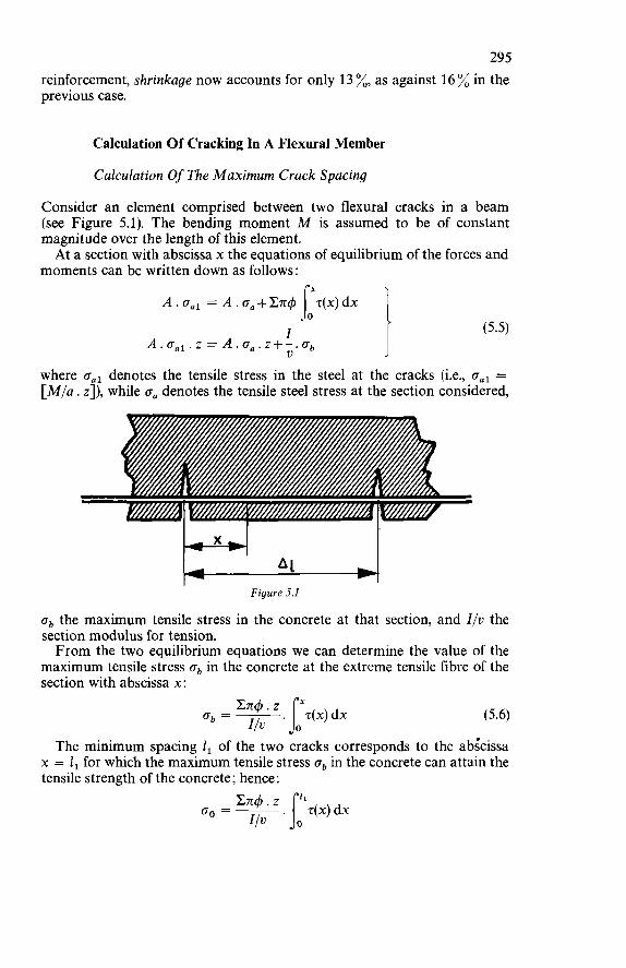
29 5 reinforcement, shrinkage now accounts for only 13 %, as against 16 % in the previous case.
Calculation Of Cracking In A Flexural Member
Calculation Of The M a x i m u m Crack Spacing
Consider an element comprised between two flexural cracks in a beam (see Figure 5.1). The bending moment M is assumed to be of constant magnitude over the length of this element. At a section with abscissa x the equations of equilibrium of the forces and
moments can be written down as follows:
A.oal =A.o,+Cmj T(x)dx
I I A . Oal. z = A . z+-. ob u
(5.5)
where oal denotes the tensile stress in the steel at the cracks (i.e., oal = [ M / a . z]), while o, denotes the tensile steel stress at the section considered,
Figure 5.1
ob the maximum tensile stress in the concrete at that section, and I/u the section modulus for tension. From the two equilibrium equations we can determine the value of the
maximum tensile stress ob in the concrete at the extreme tensile fibre of the section with abscissa x:
The minimum spacing 1, of the two cracks corresponds to the abkissa x = 1, for which the maximum tensile stress ob in the concrete can attain the tensile strength of the concrete; hence:
296
distributed, i.e., if their spacing has its maximum value: But the most unfavourable case evidently occurs if the cracks are least well
Al,,, = 21, The calculation of the maximum spacing of the cracks therefore consists
in solving the equation:
Hence :
Into this expression we can also introduce the resultant N of the com- pressive forces in the section under the action of the cracking moment, noting that:
1 Mcracking = N . z = 60 .i
Hence :
and therefore :
U V N = -.O0 Z
N' Al,,, = 2. En4 . zaverage
Calculation Of The Maximum Crack Width
The calculation of the width of a flexural crack can be reduced to the calcula- tion of the difference between the respective elongations of the steel and the concrete in the block comprised between two consecutive cracks, taking account of the sliding of the reinforcement in relation to the surrounding concrete in accordance with the normal action of bond. Consider a section with abscissa x. The steel strain can be taken as:
while the 'concrete strain is the result of the elastic elongation and the shrinkage :
*
Hence :
w,,, = 2 JOA"' (5 - 3 + dx Ea
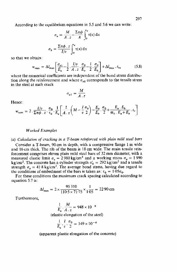
297 According to the equilibrium equations in 5.5 and 5.6 we can write:
so that we obtain:
where the numerical coefficients are independent of the bond stress distribu- tion along the reinforcement and where corresponds to the tensile stress in the steel at each crack
M (Tal = - A.z
Hence :
Worked Examples
(a) Calculation of cracking in a T-beam reinforced with plain mild steel bars Consider a T-beam, 90 cm in depth, with a compressive flange 1 m wide
and 16 cm thick. The rib -of the beam is 18 cm wide. The main tensile rein- forcement comprises eleven plain mild steel bars of 32 mm diameter, with a measured elastic limit oe = 2 980 kg/cm2 and a working stress oa = 1990 kg/cm2. The concrete has a cylinder strength ab = 292 kgjcm2 and a tensile strength o,, = 41.8 kgjcm2. The average bond stress, having due regard to the conditions of embedment of the bars is taken as: zo = 1.050,. For these conditions the maximum crack spacing calculated according to
equation 5.7 is: 1
X- = 22.90~~1 95 310 110.5 x 71.75 1.05 Al,,, = 2 x
Furthermore,
- 948 x lop6 1 M E,,'A.z - __-
(elastic elongation of the steel) 1 I o0 = 1 4 9 ~ E a ' ~ ' 2
(apparent plastic elongation of the concrete)
298
(elastic elongation of the concrete) E,, = 0.50~~ = 150 x
(for average shrinkage of the concrete: E, = 3 x Hence, for the maximum crack width (equation 5.8):
w,,, = (948 - 149 - 68 + 150) x 10- x 229 = 0.202 mm It should be noted that, in this ordinary case, shrinkage accounts for about
17 % of the maximum crack width. As for the elastic elongation of the con- crete, this accounts for under 8 %. (b) Calculation of cracking in a T-beam reinforced with medium-tensile
The T-beam is of the same external dimensions as the one in the previous example, but in this case the reinforcement consists of eleven medium-tensile 'deformed' (high-bond) bars of 22 mm diameter, with a measured elastic limit oe = 6 980 kg/cm2 and a working stress o, = 4 650 kg/cm2. The con- crete has a cylinder strength ob = 260 kg/cm2 and a tensile strength o, = 40.1 kg/cm2. The average bond stress, having due regard to the conditions of embedment of the bars, is taken as: zo = 2.670,. For these conditions the maximum crack spacing calculated according
to equation 5.7 is:
deformed bars
58710 1 ~ = 9.74cm 58.4 x 77.28 ' 2.67 Al,,, = 2~
Furthermore,
- -- - 2214~10-~ E, 'A.z (elastic elongation of the steel)
1 I O, = 239 x lop6 E,'v' 2 (apparent plastic elongation of the concrete)
(elastic elongation of the concrete)
(for average shrinkage: E, = 3 x lop4) E,, = 0.585~~ = 175 x
Hence, for the maximum crack width (equation 5.8): w,,, = (2 214-239-69+ 175) x x 97.4 = 0.203 mm
299 So, thanks to the high bond developed by the reinforcement, the maximum
width of the cracks remains of the same order of magnitude as in the previous example. O n the other hand, because of the substitution of medium-tensile steel for
mild steel and the corresponding reduction of the geometrical percentage of reinforcement, shrinkage now accounts for only 8% instead of 17% as in the previous case. Also, the proportion associated with the elastic elongation of the concrete has been reduced from 8 % to a mere 3 %.
5.2.5 CONCLUSIONS
In the case of ‘normally reinforced’ members a comparison between the complete analytical calculation and experimental measurements of crack widths yields various practical conclusions which can facilitate the applica- tion of this calculation procedure by designers.
Cracking is a random and fundamentally dispersive phenomenon which it would be illusory to pretend to define in precise terms. Anyway, the designer is interested only in the order of magnitude of the crack widths. The only purpose and only significance of the systematic application of the
analytical formulae is to be able to compare the respective influences of the various parameters of the phenomenon and to justify the approximations that are indispensable to practical design calculations. In the most commonly encountered cases the overall effect of shrinkage,
elastic deformation and apparent plastic deformation of the concrete can be considered negligible, for the error associated with this approximation is found in practice to be distinctly less than the dispersion (scatter) of the experimental measurements. This being so, the expressions for the maximum crack width given above
can be simplified as follows:
(a) Concentric tension:
where the bond stress z,, is the average ‘flexural’ bond stress.
(b) Simple bending:
where the bond stress zo is the average ‘flexural’ bond stress. Provided that the width bo of the web of the beam considered is less than four times the sum of the diameters of the bars forming the reinforcement (with plain bars) or less than twice that sum (with deformed bars), the calculation of flexural cracking can be simplified and reduced to the calculation of tensile cracking applied to the ‘embedment zone’ of the main tensile reinforcement (‘tie-rod
300 analogy’). The bond stress q, to be introduced into the calculation must obviously be the ‘anchorage’ bond stress and not the ‘flexural’ bond stress.
5.3 PRACTICAL CHECKING OF CRACKING IN REINFORCED CONCRETE
5.3.1 PRINCIPLES OF THE CHECKING OF CRACKING
Nature And Validity Of The Practical Rules For The Checking Of Cracking
Having regard to the basic assumptions, a calculation for checking the cracking of a reinforced concrete member is possible only for transverse flexural or tensile cracking in the ‘embedment zone’ of the main tensile reinforcing bars and cannot systematically take account of the influence (if any) of shear force. It must therefore be admitted that a check of this kind covers only a
relatively small proportion of the cracking phenomena that are liable to occur in a reinforced concrete structure. More particularly, it does not include longitudinal cracks which may give rise to tangential actions between the web and the zone containing the main tensile reinforcement, nor does it include the ‘diagonal’ (inclined) cracks that develop over the entire depth of the web or rib as a result of shear force, whether or not acting in combination with other loadings. And yet these cracks are often more dangerous from the point of view of corrosion than the transverse cracks occurring in the embedment zone of the main tensile reinforcement. So one must avoid attributing to the theoretical calculation of cracking
various virtues that it does not possess or regarding it as having in practice a universal scope or major importance which are justified neither by its degree of accuracy nor by its range of validity. It would indeed be misleading to claim to be able to safeguard against the
possible effects of cracking merely by limiting the theoretical maximum width of the flexural and tensile transverse cracks. The practical object is merely to give guidance to the designer in making
appropriate structural arrangements (concerning the diameter and distribu- tion of the bars, in particular) and in avoiding certain gross errors of design which might result in concentrations and excessive widths of flexural and tensile cracks. This being so, the calculation of cracking should be confined to verijìcation of the ‘Rules of good design’. For practical purposes these rules may be presented in the form of a
relation between the working stress, the percentage and the diameter of the main tensile reinforcing bars, having due regard to the bond properties of the steel and the tensile strength of the concrete. These rules can be established and applied for various classes of structures based on certain conditions of preservation and service. But on no account must these rules explicitly state the maximum value of the crack widths, for the measurement and
30 1 checking of these widths would run into insurmountable difficulties and would be of entirely illusory value (Section 5.2.2).
Classification Of Structures According To The Permissible Crack Widths
Class 1 : Structural Members Which Must Ensure Watertightness Or Are Exposed To Aggressive Actions
These are members in which cracking is very harmful, either because they have to be watertight (e.g., walls of tanks, locks or dry-docks) or because they are exposed to a particularly aggressive medium. For such members it is agreed to introduce implicitly into the cracking
calculation, for establishing appropriate rules for designing the reinforce- ment, an upper limit of 0.1 mm for the maximum width of the cracks. In certain cases of walls provided with a low percentage of reinforcement this limit may result in apparently severe rules, but this severity can be substan- tially mitigated by taking account of the favourable effect of the swelling of the concrete in all cases where the walls in question are permanently in contact with water or with an atmosphere saturated with water vapour (Section 5.2.3).
Class 2: Unprotected Ordinary Structural Members
In these members cracking of the tensile zone is harmful either because they are exposed to the effects of the weather (as is the case with outdoor structures such as bridges and other civil engineering works) or because they are exposed to a humid and aggressive atmosphere (as in the case of certain industrial structures, factory roofs, or workshop buildings in which considerable quantities of water vapour are liable to be produced). This class may also be taken to include members which have to support very fragile claddings or facings which would suffer harmful consequences from excessive cracking and deformation. For such members it is agreed to introduce implicitly into the cracking
calculation, for establishing appropriate rules for designing the reinforce- ment, an upper limit of 0.2 mm for the maximum width of the cracks.
Class 3 : Protected Ordinary Structural Members
In these members cracking is not harmful and does not have any serious adverse effects upon the preservation of the reinforcing steel nor upon the durability of the structure. For such members it is agreed to introduce implicitly into the cracking

302 calculation, for establishing appropriate rules for designing the reinforce- ment, an upper limit of 0.3 mm for the maximum width of the cracks.
5.3.2 DESIGN RULES FOR THE M A I N REINFORCEMENT
Preliminary Assumptions
These practical rules, which are applicable to all structural members loaded in bending, have been established for each of the classes of structures defined in the foregoing - i.e., classes 1,2 and 3 - on the basis of simplified assump- tions and average values as indicated in the following: For the practical application of the calculation it is assumed that the main
tensile reinforcing bars are satis$actorily embedded in concrete; this means more particularly that the bars must have an amount of cover at least equal to their diameter 4. Consequently, the average anchorage bond stress zo is assumed to be
independent of the embedment and is taken as three-quarters of the tensile strength o. of the concrete in the case of plain bars and to five-quarters thereof in the case of deformed bars. The tensile strength o. ofthe concrete is assumed to have an average value
of 40 kg/cm2, but this value will in practice only enter into the design of ‘under-reinforced members in which cracking is not of a systematic character and can be calculated only by considering the bond of the steel in the concrete. The practical scope of this assumption is therefore limited.
Design Of Under-Reinforced Members (Cracking Not O f A Systematic Character)
Application of the preliminary assumptions to the expression at the end of Section 5.2.3 yields the following results :
Class 1 : Watertight Structures Or Structures Exposed To Aggressive Atmosphere
The rules for checking the cracking for class 1 are based on the condition: w,,, + O. 1 mm
i.e., with reference to the expression derived in Section 5.2.3:
Now (AIC.rr4) = (4/4) and the average anchorage bond stress zo can be replaced by its value as reasoned above. Then:
371 oo.E, . +for 1 plain bars) 4 m J i F . m 10
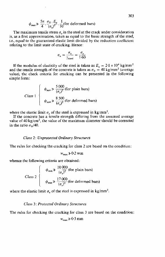
303 571 oo.E, 1
. -(for deformed bars) @mrn> 4.02 10
The maximum tensile stress o. in the steel at the crack under consideration is, as a first approximation, taken as equal to the basic strength of the steel, i.e., equal to the guaranteed elastic limit divided by the reduction coefficient relating to the limit state of cracking. Hence:
If the modulus of elasticity of the steel is taken as E, = 2.1 x lo4 kg/mm2 and the tensile strength of the concrete is taken as go = 40 kg/mm2 (average value), the check criteria for cracking can be presented in the following simple form:
(for plain bars) 5 O00 4 m m + - (aJ2
q5,,,,,, > (for deformed bars) Class 1
where the elastic limit oe of the steel is expressed in kg/mm2. If the concrete has a tensile strength differing from the assumed average
value of 40 kg/cm2, the value of the maximum diameter should be corrected in the ratio 00/40.
Class 2 : Unprotected Ordinary Structures
The rules for checking the cracking for class 2 are based on the condition:
wmaX > 0.2 mm whence the following criteria are obtained:
q5,,,,,, > =(for plain bars) (oJ2
4,,,,,, > E (for deformed bars) i Class 2
where the elastic limit 6, of the steel is expressed in kg/mm2.
Class 3 : Protected Ordinary Structures
The rules for checking the cracking for class 3 are based on the condition: wmax > 0.3 mm
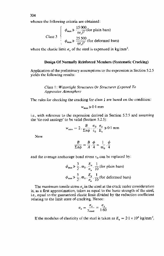
304 whence the following criteria are obtained:
15 O00 4mm> -T(for plain bars)
4,,,,,,> (for deformed bars)
(ce) 25 500 (0,)
Class 3
where the elastic limit o, of the steel is expressed in kg/mm2.
Design O f Normally Reinforced Members (Systematic Cracking)
Application of the preliminary assumptions to the expression in Section 5.2.5 yields the following results:
Class 1 : Watertight Structures Or Structures Exposed To Aggressive Atmosphere
The rules for checking the cracking for class 1 are based on the condition: wmax k O. 1 mm
i.e., with reference to the expression derived in Section 5.2.5 and assuming the 'tie-rod analogy' to be valid (Section 5.2.5):
Now
and the average anchorage bond stress zo can be replaced by:
q5,,,,,, # ?. 3 mo . - E, . - 1 (for plain bars) u, 10
&,,,,,, k 5 wo . - E, . - 1 (for deformed bars) a, 10
The maximum tensile stress o, in the steel at the crack under consideration is, as a first approximation, taken as equal to the basic strength of the steel, i.e., equal to the guaranteed elastic limit divided by the reduction coefficient relating to the limit state of cracking. Hence:
If the modulus of elasticity of the steel is taken as E, = 2.1 x lo4 kg/mm2,
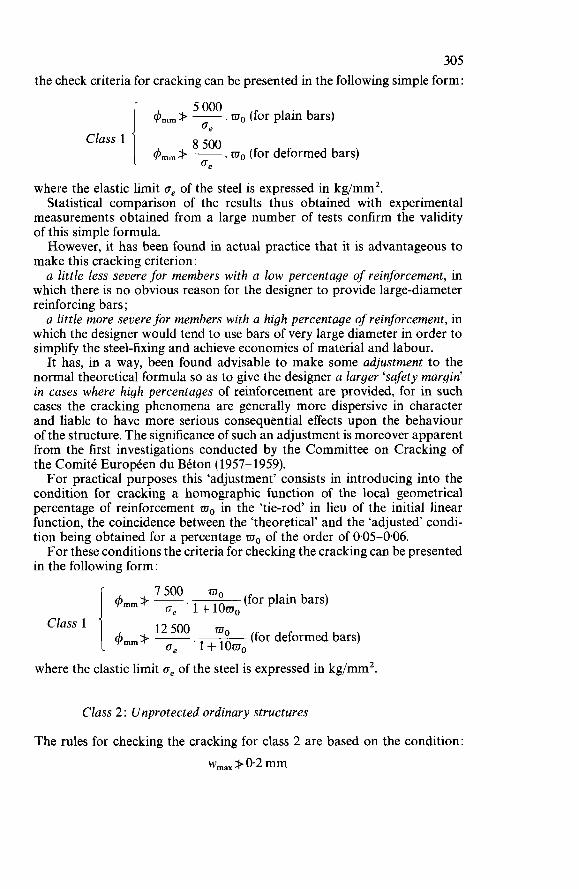
305 the check criteria for cracking can be presented in the following simple form:
. wo (for plain bars) 5 O00 ce I ce
4 m m k ~
4m,+ F. wo (for deformed bars) Class 1
where the elastic limit ce of the steel is expressed in kg/mm2. Statistical comparison of the results thus obtained with experimental
measurements obtained from a large number of tests confirm the validity of this simple formula. However, it has been found in actual practice that it is advantageous to
make this cracking criterion: a little less severe for members with a low percentage of reinforcement, in
which there is no obvious reason for the designer to provide large-diameter reinforcing bars ;
a little more severe for members with a high percentage of reinforcement, in which the designer would tend to use bars of very large diameter in order to simplify the steel-fixing and achieve economies of material and labour. It has, in a way, been found advisable to make some adjustment to the
normal theoretical formula so as to give the designer a larger ‘safety margin’ in cases where high percentages of reinforcement are provided, for in such cases the cracking phenomena are generally more dispersive in character and liable to have more serious consequential effects upon the behaviour of the structure. The significance of such an adjustment is moreover apparent from the first investigations conducted by the Committee on Cracking of the Comité Européen du Béton (1957-1959). For practical purposes this ‘adjustment’ consists in introducing into the
condition for cracking a homographic function of the local geometrical percentage of reinforcement wo in the ‘tie-rod’ in lieu of the initial linear function, the coincidence between the ‘theoretical’ and the ‘adjusted condi- tion being obtained for a percentage wo of the order of 0.05-0.06. For these conditions the criteria for checking the cracking can be presented
in the following form:
4,mk 7500 wo (for plain bars)
4mm+ E wo (for deformed bars)
ge ‘l+l0wo
ce . 1 + loa, Class 1
where the elastic limit ce of the steel is expressed in kg/mm2
Class 2 Unprotected ordinary structures
The rules for checking the cracking for class 2 are based on the condition: w,,, k 0.2 mm
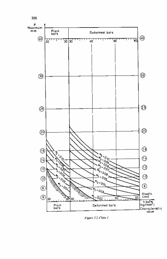
306
4 Maximum m m
@
@
@
e
6
Deformed bars Plain bo rs
I I I I ) I I I I I I I I ) I I l I I l I I I I I I I ' ' l ' ' I 6 \ 20 30 30 LO 50' I
\\
Figure 5.2. Class 1
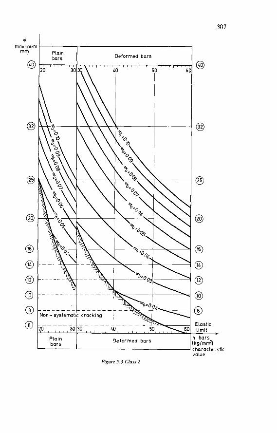
307
d maximum m m
@3
8
o
@
@ o o @ @ @
Plain bars - 3(
20
. - - - - - _ - Non- systemat . _ - - - _ - !O 3c
Piain bars
I I , , ,
Deformed bars
Deformed bars
o
o
@ o o @ c9 Elastic limit
I bars kg/mm2ì :haraderistic
- value
Figure 5.3 Class 2
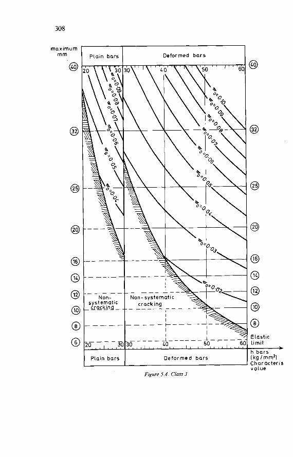
308
m m I @'
Piain bars
_ _ - - - Non-
systematic . Cr 0 king -
o-,--, 3
Plain bars
Deformed bars
Deformed bars
Eiastic Limit * h bars (kg / mm2) Char ac ter is value
Figure 5.4. Class 3
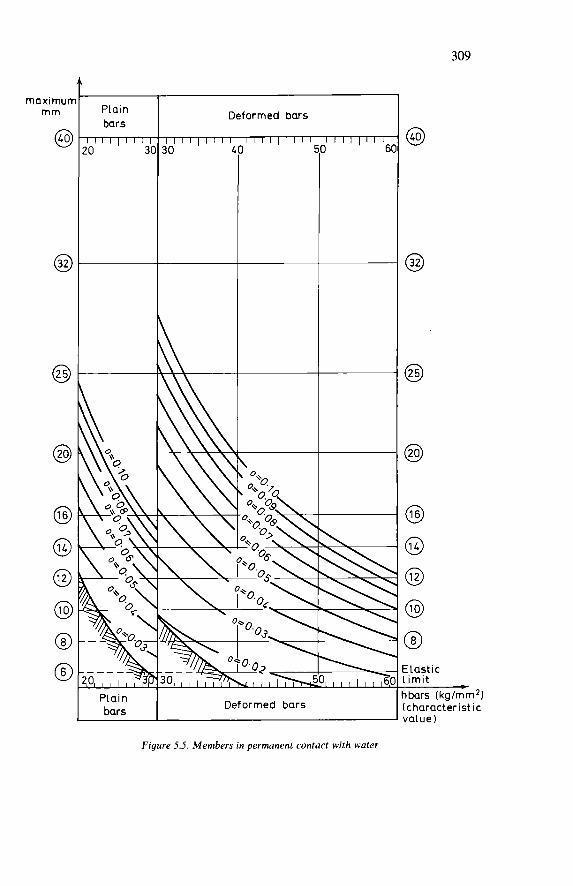
309
maximun m m Piain
bars l i i l ~ i i l l !O 3(
Deformed bars
Piain bars Deformed bars
!Lastic .¡mit ]bars (kg/mm2ì :character ist ic value)
Figure 5.5. Members in permanent contact with water
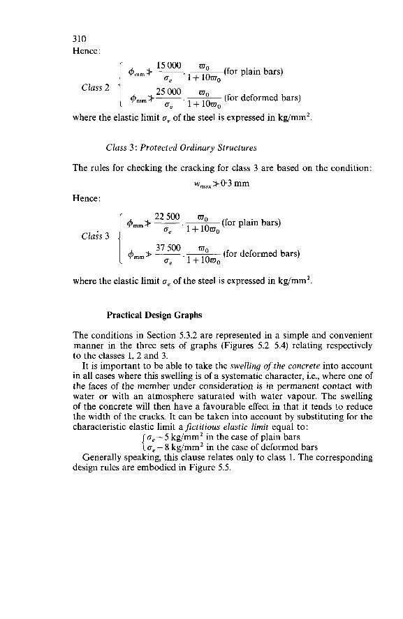
310 Hence :
4 m m + - (for piain bars) l5 'Oo ae .I + IOWo
where the elastic limit ae of the steel is expressed in kg/mm2
Class 3: Protected Ordinary Structures
The rules for checking the cracking for class 3 are based on the condition: w,,, + 0.3 mm
Hence :
&,,,,+ mg (for plain bars) a, '1+10mo Clais 3 I 4,,+ -500 mg (for deformed bars)
ae ' 1 + lomo
where the elastic limit a, of ihe steel is expressed in kg/mm2.
Practical Design Graphs
The conditions in Section 5.3.2 are represented in a simple and convenient manner in the three sets of graphs (Figures 5.2-5.4) relating respectively to the classes 1, 2 and 3.
It is important to be able to take the swelling of the concrete into account in all cases where this swelling is of a systematic character, i.e., where one of the faces of the member under consideration is in permanent contact with water or with an atmosphere saturated with water vapour. The swelling of the concrete will then have a favourable effect in that it tends to reduce the width of the cracks. It can be taken into account by substituting for the characteristic elastic limit a fictitious elastic limit equal to:
a, - 5 kg/mm2 in the case of plain bars { o, - 8 kg/mm2 in the case of deformed bars Generally speaking, this clause relates only to class 1. The corresponding
design rules are embodied in Figure 5.5.
6
CALCULATIONS OF FLEXURAL DEFORMATIONS
6.1 RECAPITULATION OF THE FUNDAMENTAL ASSUMPTIONS FOR THE CALCULATION OF DEFORMATIONS
The calculation of the deformations of prismatic structural members loaded in bending and compression should take account as accurately as possible of the various physical and mechanical phenomena that characterise the elasto-plastic behaviour of the concrete in compression and the cracking of the concrete in tension. In view of the uncertain and random character of many parameters, the
deformations can, with sufficient accuracy for practical purposes, be cal- culated by means of the conventional methods of Strength of Materials based on the application of the elastic theory, subject to applying the three following fundamental assumptions : (a) The geometrical cross-sections of the member under consideration
should first be made ‘homogeneous’ by multiplying the steel cross- sectional area by the modular ratio, i.e.:
Ea B+-.A Eb where A and B denote the steel and concrete cross-sectional areas respectively, E, denotes the modulus of elasticity of the steel (for which a value of 2 100 O00 bars should be adopted) and Eb the modulus of elasticity of the concrete (for which the instantaneous modulus Ebo or the long-term modulus EL, should be adopted, according as loads of short or long duration are involved).
(b) The basic values of the tensile steel strain E, at the various sections should, for the purpose of introducing them into the conventional calculation of the deformations in the case of a member that is not entirely in compression, take account of the cracking of the concrete
31 1

312 in tension and also allow for the corresponding effects of the bond of the main tensile reinforcement.
(c) The basic values of the compressive concrete strain E; at the various sections should, for the purpose of introducing them into the con- ventional calculation of the deformations, take account of the instan- taneous plasticity, the long-term plasticity and the shrinkage of the concrete.
6.2 DETERMINATION OF THE BASIC STEEL AND CONCRETE STRAINS
The basic values of the steel and concrete strains to be introduced into the general analysis for the limit state of deformation of a member loaded in bending and compression should be referred to the ‘basic strength’ of the steel and the concrete, respectively, corresponding to that limit state (in accordance with Sections 4.3.2 and 4.3.3 of Part 1).
6.2.1 DETERMINATION OF THE STEEL STRAIN
The determination of the tensile steel strain E, in the limit state of deformation of a member loaded in bending and compression, but not in compression over the entire cross-section, should take into account as accurately as possible the cracking of the concrete in tension and the corresponding effects of the bond of the main tensile reinforcement. In practice, for each section considered, the steel strain E, in the limit state of deformation should be taken as:
where 0, denotes the basic tensile strength of the steel, Ob the basic tensile strength of the concrete, wo the geometrical percentage of main tensile reinforcement with reference to the embedment section of the concrete, and E, the modulus of elasticity of the steel (taken as 2 100 O00 bars). The first term of this expression represents the elastic strain of the steel
assumed not to be embedded in concrete. The second term takes account of the effects of the bond of main tensile reinforcement in the zone where cracking occurs. This calculation is based on the general theory of cracking as set forth in Chapter 5 of Part 2 of this Manual.
6.2.2 DETERMINATION OF THE CONCRETE STRAIN
The determination of the compressive concrete strain E; in the limit state of deformation of a member loaded in bending and compression should take into account as accurately as possible the various physical and mechanical phenomena that characterise the elasto-plastic behaviour of the concrete
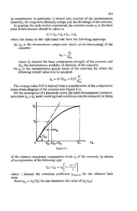
313 in compression. In particular, it should take account of the instantaneous plasticity, the long-term plasticity (creep) and the shrinkage of the concrete. In practice, for each section considered, the concrete strain E; in the limit
state of deformation should be taken as: E; = &;o + &;i + E;, + E;,
where the terms on the right-hand side have the following meanings : (a) &bo is the instantaneous compressive elastic strain (shortening) of the
concrete :
where ób denotes the basic compressive strength of the concrete and ELo the instantaneous modulus of elasticity of the concrete.
(b) &Li is the instantaneous plastic strain of the concrete, for which the following overall value is to be adopted: - =’ &Li = 0.15~;~ = 0.15:
E b O
The average value 0.15 is derived from a consideration of the compressive stress-strain diagram of the concrete (see Figure 6.1). O n the assumption of a parabolic curve, the total instantaneous compres-
sive strain &, + &Li under working load conditions can be estimated, in terms
Figure 6.1
of the ultimate maximum compressive strain EO of the concrete, by means of an expression of the following type:
&;o+&;i = &u[1:.71] where y denotes the reduction coefficient yconcrete for the ultimate limit state. Since &i0 = (4,/2y), we can determine the value of ELJ JE^^).
314 Depending on the value of the reduction coefficient yconcrete, which ranges
from 2.10 to 2.50, the ratio &bi/&bO varies from 0.135 to 0.160, which justifies the adoption of the average value of 0.15. (c) &Lm is the long-term compressive plastic strain of the concrete, which,
if no experimental creep measurements are available, should be taken as the following average value:
ob &km = 2*. &Lo = 2*.
where i,b denotes the ratio of the long-term (sustained) load to the total load on the member considered.
The total long-term compressive strain (creep shortening) of the concrete, which is applicable only to the proportion $ of the load, is equal to:
Hence : -, o
&bO+&b, = (1+2*).+ = (1+2$), 4 0 E,, and therefore :
ob &;, = 2*. &bo = 2*.
The estimation of $ does not present any practical difficulty. With refer- ence to the definition of characteristic loadings it can be said that the ratio t,ú represents the proportion constituted by the permanent loads and fixed superimposed loads S, in relation to the total characteristic loadings that have to be considered in the calculation of the deformations. Hence we have, as a first approximation :
s, for buildings * = s,+ 1.20SP1 s, * = S, + 1.3OSp, for other structures
A further simplification can be adopted in the case of ordinary buildings, not of an exceptional character, for which the following approximate values may be used:
$ = for service floors of buildings for public use * = a for service floors of buildings for private use $ = for roof structures of all buildings
315 (d) &ir is the shrinkage of the concrete, measured under conditions strictly
comparable to those on the construction site. In all, for each section of a member loaded in bending or compression,
the compressive strain of the concrete in the limit state of deformation should accordingly be taken as:
E; =
6.3 GENERAL CALCULATION OF DEFLECTION CURVES AND DEFLECTIONS
The general calculation of deflection curves and deflections consists in: (a) establishing, for a sufficient number of sections distributed along the
member considered, the geometrical expression for the curvature as a function of the basic strains of the steel and concrete in the limit state of deformation;
(b) deducing therefrom the relationship for the variation of the curvature over the entire length of the member;
(c) determining the deflection curve by means of a double integration. The maximum ordinate of the deflection curve defines the deflection of the
member.
6.3.1 C R A C K E D MEMBERS
For members subjected to simple bending or composite bending which are partially in tension, and cracked, the curvature at any particular section with the abscissa x is equal to:
where d2f /dx2 is the second derivative of the deflection curve with respect to the abscissa of the section considered, while E, and E; are the basic steel and concrete strains estimated for the limit state of deformation, and h denotes the effective depth of the section. O n replacing E, and E; by the values derived for them earlier on in this
chapter, we obtain: -
- g b a,-- 2mo + (1.15 + 21))
-- d2f E a
dx2 - h
316 and thence, by double integration, the function f(x) defining the deflection curve. The deflection of the member is defined as the maximum value of f(x).
6.3.2 U N C R A C K E D MEMBERS
For members subjected to eccentric compression which are entirely in compression, and not cracked, the curvature at any particular section with the abscissa x is equal to:
1 - d2f - 1 ~b I - 1 & L i I r dx2- h* -~ -
where d2fldx2 is the second derivative of the deflection curve with respect to the abscissa of the section considered, E; is the basic compressive strain of the concrete at the most compressed fibre (corresponding to the basic strength $b of the concrete; cf. Section 6.2.2), &Li is the compressive strain of the concrete at the least compressed fibre (corresponding to the concrete stress obi at that fibre, calculated by the same procedure as indicated in Sec- tion 6.2.2), and h, denotes the total geometrical depth of the section. O n replacing E; and &Li by the values derived for them, we obtain:
d'f (1.15 + 2$) (ob - abi) a?= h, ' Go
where the value of obi is obtained from the stress distribution diagram of the concrete at the section considered. By double integration we then obtain the function f(x) defining the deflec-
tion curve. The deflection of the member is defined by the maximum value of f(x).
6.4 SIMPLIFIED CALCULATION FOR ORDINARY BUILDINGS
In the case of buildings for public or private use and not of an exceptional character the general calculation of deflection curves and deflections can be replaced by a simplified calculation of the maximum deflection in the limit state of deformation, applicable to all members loaded in simple bending and with a mechanical percentage of tensile reinforcement not exceeding 0.25. If these conditions are satisfied, the margin of approximation (in relation
to the results obtained by applying the general calculation) will not exceed f 20 %. On the other hand, if they are not satisfied, e.g., in members contain- ing a very high percentage of reinforcement, the designer should use the general calculation procedure set forth in the previous section. The simplified calculation consists in calculating the total maximum
deflection f as the sum of two partial deflectionsf, and fII: (a) The first partial deflection fi relates to the uncracked state (called
317 ‘state I’) and represents the deflection attained at the time just before cracking of the tensile zone of the member occurred:
where MI denotes the value of the bending moment at cracking (estimated for the ‘homogeneous’ section and with reference to the tensile strength o. of the concrete), Ek0 the instantaneous modulus of elasticity of the concrete, I, the moment of iflertia of the homogeneous section, $ the proportion of the permanent loads and fixed superimposed loads in relation to the whole of the characteristic loadings, 1 the span of the member, and B the numerical coefficient occurring in the standard deflection formulae based on the theory of elastic behaviour. The general expression for the deflection of an elastic member is:
f = ß . - . l M 2 E.I
The coefficient fi depends more particularly on the structural arrangements and on the nature and mode of application of the loads and superimposed loads. In ordinary buildings the loads are often uniformly distributed, and for such loads the coefficient fi has the following values : & for a freely supported beam & for a beam rigidly restrained at both ends &for a beam freely supported at one end and rigidly restrained at the
i for a cantilever (b) The second partial deflectionf, relates to the cracked state (‘state 11’)
and represents the deflection attained after cracking of the tensile zone of the member has occurred :
other
where M denotes the total bending moment corresponding to the whole of the characteristic loadings, E, the modulus of elasticity of the steel (for which a value of 2 100 O00 bars should be adopted), A the cross-sectional area and Q the mechanical percentage of the main tensile reinforcement. The other symbols are as previously defined. (c) Finally, the total deflection f = fI +frI must not exceed the following
limit value:
An additional simplification may be adopted if MI <3M or if the member under consideration has a compressive flange whose effective width is more than five times the width of the rib (web). In either case the deflectionfcan be taken as equal to the following limit value:
. l2 M f = B.(1+2$). E,. A . h2(1 -2Q) (i -+.I)
318 This last-mentioned simplification is applicable to the great majority
of ribbed floors of ordinary buildings. The approximate values for $ indicated in Section 6.2.2 may be adopted for these. However, an uncertainty may occur in the estimation of the coefficient ß
because of the possibly varying degree of continuity between adjacent floor slabs or because of the incompleteness of their fixity in the external walls. O n account of this the coefficient (ß) is generally less than (which is the value relating to freely supported members) but remains above & (the value relating to members completely fixed at both ends). For practical purposes the average intermediate value may be adopted :
ß=' 12
Adopting this value for ß and taking M = a,. A. z = (a,. A. z/1.80) we obtain the following simplified expression for the maximum deflection :
or
or, approximately:
Ge 1 1.80 . E,( 1 - 2m) ' h
For the check condition for the limit state of deformation f 11 < (flZ),imi, w e can therefore substitute the condition for the limit value of the slenderness ratio:
where the guaranteed minimum elastic limit a, of the steel is expressed in bars. This condition is applicable only to flexural members with a mechanical percentage of reinforcement m not exceeding 0.25.
First example:
Service floor of a residential building, reinforced with mild steel bars: 1 -
max = 150
43x 107 i i x-x-(~-~w) = 83(1-2~~) (i)max = 2.4 x lo3 1.50 150

319 Second example. Service floor of a school building, reinforced with grade 40 steel bars:
4.5x 10⁷ i i x-x-(~-~w) = 27(1-2~7) (i)max = 4 x lo3 1.40 300
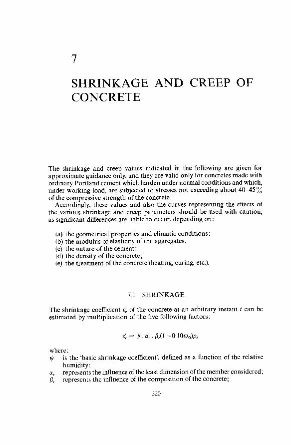
7
SHRINKAGE AND CREEP OF CONCRETE
The shrinkage and creep values indicated in the following are given for approximate guidance only, and they are valid only for concretes made with ordinary Portland cement which harden under normal conditions and which, under working load, are subjected to stresses not exceeding about 40-45 % of the compressive strength of the concrete. Accordingly, these values and also the curves representing the effects of
the various shrinkage and creep parameters should be used with caution, as significant differences are liable to occur, depending on:
(a) the geometrical properties and climatic conditions; (b) the modulus of elasticity of the aggregates; (c) the nature of the cement; (d) the density of the concrete; (e) the treatment of the concrete (heating, curing, etc.).
7.1 SHRINKAGE
The shrinkage coefficient E: of the concrete at an arbitrary instant t can be estimated by multiplication of the five following factors :
E: = lj . CI,. p,(l-O~lOaO)p,
where : lj
CI, /3,
is the ‘basic shrinkage coefficient’, defined as a function of the relative humidity ; represents the influence of the least dimension of the member considered; represents the influence of the composition of the concrete;
3 20
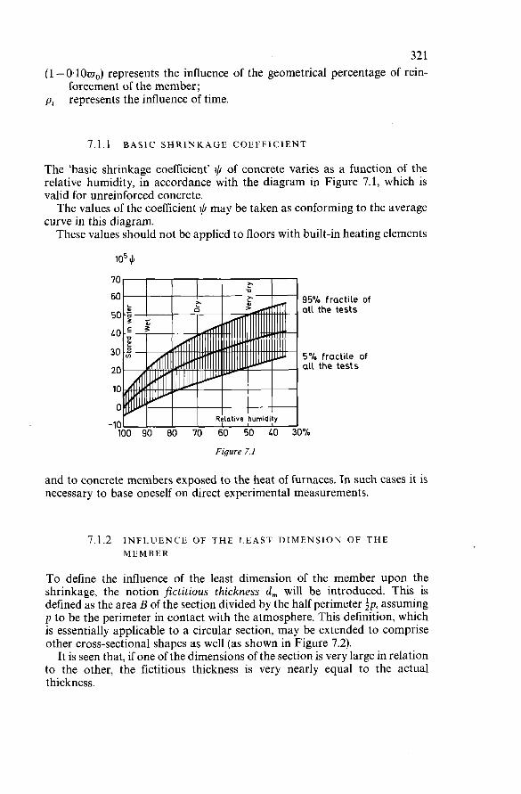
32 1 (1 - O.1Oar0) represents the influence of the geometrical percentage of rein- pt
forcement of the member; represents the influence of time.
7.1.1 BASIC SHRINKAGE COEFFICIENT
The ‘basic shrinkage coefficient’ $ of concrete varies as a function of the relative humidity, in accordance with the diagram in Figure 7.1, which is valid for unreinforced concrete. The values of the coefficient t,b may be taken as conforming to the average
curve in this diagram. These values should not be applied to floors with built-in heating elements
io5 4 70
60 95% fractile of 50
LO
30
20
10
O -10 100 90 80 70 60 50 LO 30%
all the tests
5% fractile of all the tests
Figure 7.1
and to concrete members exposed to the heat of furnaces. In such cases it is necessary to base oneself on direct experimental measurements.
7.1.2 INFLUENCE OF THE LEAST DIMENSION OF THE MEMBER
To define the influence of the least dimension of the member upon the shrinkage, the notion fictitious thickness d, will be introduced. This is defined as the area B of the section divided by the half perimeter assuming p to be the perimeter in contact with the atmosphere. This definition, which is essentially applicable to a circular section, may be extended to comprise other cross-sectional shapes as well (as shown in Figure 7.2).
It is seen that, if one of the dimensions of the section is very large in relation to the other, the fictitious thickness is very nearly equal to the actual thickness.
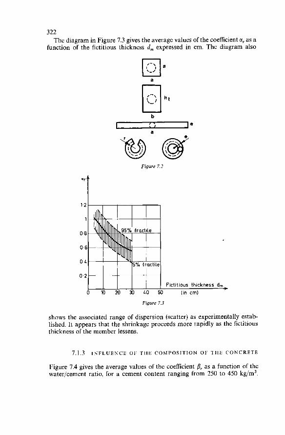
322 The diagram in Figure 7.3 gives the average values of the coefficient CI, as a
function of the fictitious thickness d, expressed in cm. The diagram also
a
b
re a
Figure 7.2
o 10 20 30 LO Fictitious thickness dm
I (in cmi Figure 7.3
shows the associated range of dispersion (scatter) as experimentally estab- lished. It appears that the shrinkage proceeds more rapidly as the fictitious thickness of the member lessens.
7.1.3 INFLUENCE OF THE COMPOSITION OF THE CONCRETE
Figure 7.4 gives the average values of the coefficient B, as a function of the water/cement ratio, for a cement content ranging from 250 to 450 kg/m3.
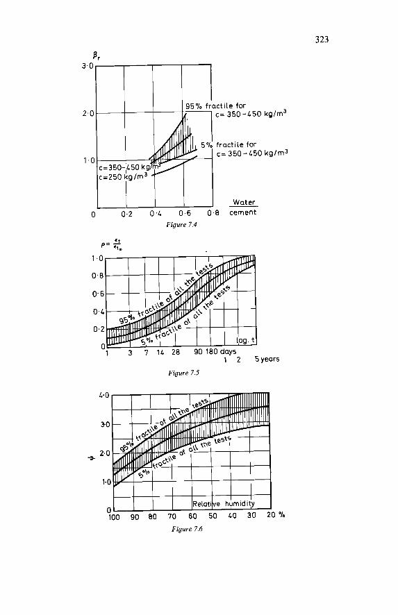
323
3.0
2.0
1.0
O 0.2 0.L ’
1 95% fractile for
5% fractile for !I .6 0.8 cement Water
C = 350 -L50 kg/m3
C = 350 - L50 kglm3
Figure 7.4
‘i p = .(.
years
Figure 7.5
L.0
3.0
2. o -3
1.0
O 100 90 80 70 60 50 LO 30 20 %
Figure 7.6
324 It also shows the associated range of dispersion (scatter), as experimentally established, for a cement content of 350-450 kg/m3.
7.1.4 INFLUENCE OF TIME
The average values of the coefficient pt which expresses the variation of the shrinkage as a function of time for constant climatic conditions are given in Figure 7.5. With this diagram it is also possible to determine the amount of shrinkage
deformation that occurs in any particular time interval (t, - ti), namely : E‘ ?(Pin - Pii)
It should finally be noted that these values are valid in the case where the concrete is not protected. If, on the other hand, suitable moist curing is applied on the site, the shrinkage is reduced by about 50 % while the concrete is still very young. In this way it is possible to obviate cracking of this con- crete, even though its tensile strength at this stage is still very low. This reduction of the shrinkage diminishes in course of time, however; at an age of four months it is no more than about 10% and tends gradually to disappear entirely over a longer period of time.
7.2 CREEP
The creep coefficient E; of the concrete at an arbitrary instant t can be estimated by multiplication of the six following factors :
where I) is the ‘basic creep coefficient’, defined as a function of the relative
humidity; a,f represents the influence of the least dimension of the member considered; ßJ represents the influence of the composition of the concrete; (1 - 0.10~~) represents the influence of the geometrical percentage of rein-
forcement of the member; represents the influence of the age of the concrete at the time of loading;
pi represents the influence of time. The creep coefficient E> is applicable to the instantaneous strain (elastic
shortening) due to a compressive stress os, assumed to be of constant magnitude, which causes creep of the concrete. Hence:
E; = I). a/. . ßs(l -O.1OWo)~. pr
O’ (in bars or kg/cm2) 0s E;, = E; .y = E S . E,, 21 OOOJOJ
7.2.1 BASIC CREEP COEFFICIENT
The ‘basic creep coefficient’ I) of the concrete varies as a function of the relative humidity, in accordance with the diagram in Figure 7.6, which is valid for unreinforced concrete.
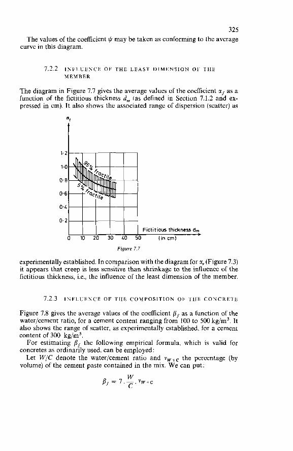
325 The values of the coefficient iI/ may be taken as conforming to the average
curve in this diagram.
7.2.2 INFLUENCE OF THE L E A S T DIMENSION OF THE MEMBER
The diagram in Figure 7.7 gives the average values of the coefficient as as a function of the fictitious thickness d, (as defined in Section 7.1.2 and ex- pressed in cm). It also shows the associated range of dispersion (scatter) as
1.2
1.0
O. 8
0.6
Fictitious thickness dm O 10 20 30 LO 50 (in crn)
Figure 7.7
experimentally established. In comparison with the diagram for CI, (Figure 7.3) it appears that creep is less sensitive than shrinkage to the influence of the fictitious thickness, i.e., the influence of the least dimension of the member.
7.2.3 INFLUENCE OF THE COMPOSITION OF THE CONCRETE
Figure 7.8 gives the average values of the coefficient Pr as a function of the water/cement ratio, for a cement content ranging from 100 to 500 kg/m3. It also shows the range of scatter, as experimentally established, for a cement content of 300 kg/m3. For estimating ßf the following empirical formula, which is valid for
concretes as ordinarily used, can be employed: Let W/C denote the water/cement ratio and v w + c the percentage (by
volume) of the cement paste contained in the mix. W e can put:
W C ’ ßf = 7.- vw+c
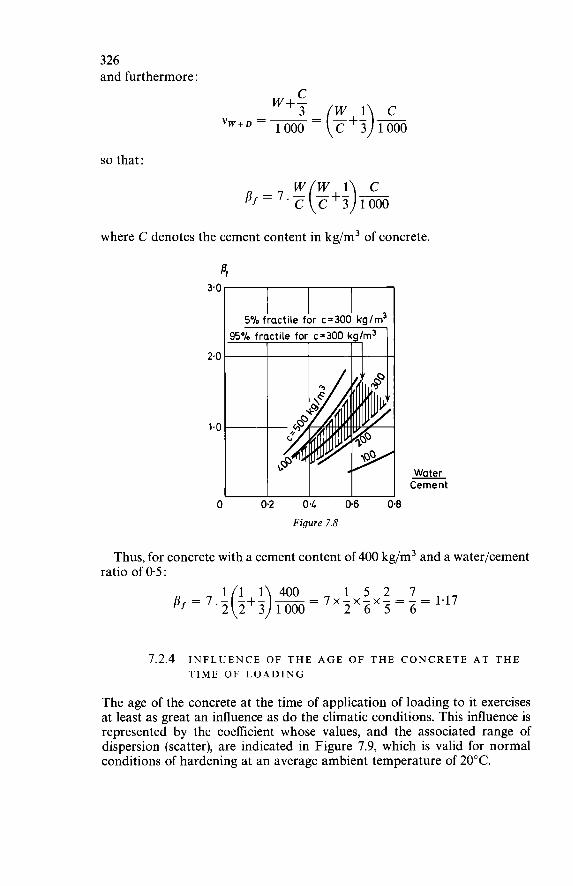
326 and furthermore:
so that:
w w 1 c pf=7.- -+- - c o c 3 1000
where C denotes the cement content in kg/m3 of concrete.
4 3.0
2.0
1.0
Water Cement
O 0.2 04 0.6 0.8 Figure 7.8
Thus, for concrete with a cement content of 400 kg/m3 and a waterlcement ratio of 0.5:
1 1 1 400 1 5 2 7 p -7.- -+- -=7x-~-x-=-=1.17 2 6 5 6 f - 2 o 2 3 1000
7.2.4 INFLUENCE OF THE A G E OF THE CONCRETE A T THE TIME OF LOADING
The age of the concrete at the time of application of loading to it exercises at least as great an influence as do the climatic conditions. This influence is represented by the coefficient whose values, and the associated range of dispersion (scatter), are indicated in Figure 7.9, which is valid for normal conditions of hardening at an average ambient temperature of 20°C.
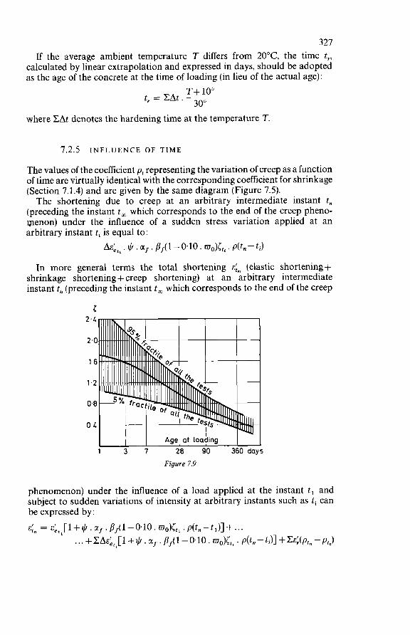
327 If the average ambient temperature T differs from 20°C, the time t,,
calculated by linear extrapolation and expressed in days, should be adopted as the age of the concrete at the time of loading (in lieu of the actual age):
T+ 10" 30" t, = CAt .-
where CAt denotes the hardening time at the temperature T
7.2.5 INFLUENCE OF TIME
The values of the coefficient pt representing the variation of creep as a function of time are virtually identical with the corresponding coefficient for shrinkage (Section 7.1.4) and are given by the same diagram (Figure 7.5). The shortening due to creep at an arbitrary intermediate instant t,
(preceding the instant t, which corresponds to the end of the creep pheno- menon) under the influence of a sudden stress variation applied at an arbitrary instant ti is equal to:
. $ . . pJ( 1 - 0.10 . wo)lti . p(t, - ti) In more general terms the total shortening &in (elastic shortening +
shrinkage shortening + creep shortening) at an arbitrary intermediate instant t, (preceding the instant t, which corresponds to the end of the creep
Age' at loading 1 3 7 28 90 360 days
Figure 7.9
phenomenon) under the influence of a load applied at the instant t, and subject to sudden variations of intensity at arbitrary instants such as ti can be expressed by : E;" = E q i + * . c(J. pJ(l-O.lO. w0)lt1 .p(t,-tl)]+ ...
. . . + 1 + $ . M~ . fis( 1 - O. 10 . mTlg)[ti . p(t, - ti)] + C&:(P~, - PtJ
328 where:
E:,, represents the elastic shortening caused by the load applied at the instant t, the variation of the elastic shortening caused by a sudden variation in the intensity of the load at an arbitrary instant ti
(t, - ti) the interval of time between application of the load and the instant at which the creep shortening is estimated
(t, - ti) the interval of time between the arbitrary instant ti at which the load undergoes a sudden variation in intensity and the instant at which the creep shortening is estimated
This general expression can serve as a basis for estimating the deformations of structural members and structures.
8
DESIGN OF SLABS AND PLANE STRUCTURES
8.1 SUBJECT AND FIELD OF APPLICATION
8.1.1 DEFINITION OF THE ENVISAGED LIMIT STATE
The safety of a structure should be analysed with regard to the various limit states corresponding to the respective criteria of unserviceability (unfitness for service). In the particular case of a plane structure loaded perpendicularly to its
middle plane the limit states to be considered are in general:
(a) the limit state of cracking; (b) the limit state of deformation; (c) the ultimate limit state (failure).
The purpose of the present chapter is to supplement the Sections relating to plane structures in Part 1 of this Manual, more particularly with regard to the analysis of the ultimate limit state. The limit states of cracking and of deformation will not be considered here.
8.1.2 DEFINITION OF THE ENVISAGED MODE OF F A I L U R E
In the case of plane reinforced concrete structures the ultimate limit state may correspond to either of the two following modes of failure: (a) failure by punching shear; (b) failure by exhaustion of the capacity to resist bending.
329
3 30 The present chapter is concerned solely with the analysis of the ultimate
limit state corresponding to failure by exhaustion of the flexural capacity, i.e., the capacity to resist bending. The ultimate limit state of failure by punching shear should be checked in all cases where locally concentrated loads are acting (superimposed loads or bearing reactions) by direct application of the rules given in Section 6.2.5 of Part I of this Manual. In the present chapter it will be assumed that the analysis for punching shear has been carried out and that therefore the safety with regard to punching shear for the plane structures under consideration is ensured.
8.2 ULTIMATE LIMIT STATE CORRESPONDING TO FAILURE BY EXHAUSTION OF THE FLEXURAL CAPACITY
(FLEXURAL FAILURE) 8.2.1 GENERAL DESCRIPTION OF THE BEHAVIOUR OF
PLANE REINFORCED CONCRETE STRUCTURES UP TO FLEXURAL FAILURE
If a plane reinforced concrete structure is subjected to gradually increasing superimposed loads, it will, in general, exhibit the following successive stages of behaviour.*
Stage Of Elastic Behaviour In this first stage of loading, the distribution of the bending moments cor- responds to the elastic distribution.
Stage Of Cracking
With further increase of the superimposed loads the cracking that develops in the tensile zones of the concrete leads to a gradual reduction of the moments of inertia of the cracked sections. This reduction is reflected in an alteration of the distribution of the bending moments in that the moments in the uncracked zones increase more rapidly, for equal load increments, than they did before cracking occurred. So long as the reinforcement remains within the range of elastic deforma-
tions, the width of the cracks will be limited.
Stage Of Plastification
Provided that the percentage of tensile reinforcement is low enough - or, to be more precise, if it is below the ‘upper critical percentage’, which is generally
*In accordance with Section 8.1.2, the structure considered here is assumed to fail as a result of exhaustion of the flexural capacity (the capacity to resist bending).
331 the case in plane reinforced concrete structures - this reinforcement will, with continuing increase of the superimposed loads, gradually develop plastic behaviour i.e., yielding, in the zones where the largest bending moments occur. The sections where the reinforcement has reached its yield point continue
to deform, but the bending moment at such sections no longer undergoes any appreciable increase, and because of this there occurs a greater amount of moment redistribution than in the previous stage. Plastification spreads gradually along narrow strips where the widest-
open cracks are concentrated. These strips may be regarded as lines, so-called ‘yield lines’. They develop according to a pattern which depends more particularly upon the shape of the structure, its support conditions, the distribution of its reinforcement, and on the method of loading. The yield line pattern as a whole is composed of straight-line segments.
Stage Of Failure
When the yield lines have developed to such an extent that the slab has become a ‘mechanism’, any very slight further increase of the superimposed loads will give rise to an unstable state of equilibrium. The structure will then continue to deform by rotation about the yield lines, until the rotation in certain zones reaches such a value as to cause destruction by crushing of the concrete in compression. The failure of these zones results in gradual exten- sion of the crushing of the concrete along the entire length of the yield lines, with a corresponding loss of the load capacity of the structure. The yield lines therefore also constitute the ‘fracture lines’ of the structure. In Figure 8.1 are shown, by way of example, the experimentally determined
and the ‘idealised’ yield line pattern of a simply-supported square slab, not anchored at the corners, subjected to four symmetrically placed concentrated loads.
8.2.2 GENERAL DESCRIPTION OF THE METHODS FOR ULTIMATE LIMIT STATE ANALYSIS
Introduction
Concerning the ultimate limit state of plane structures loaded perpendicu- larly to the middle plane, Section 5.2.1 of Part 1 of this Manual states: ‘For checking the ultimate limit state, methods which take account of
the statically indeterminate effect of plasticity, more particularly the so-called yield line theory, can permissibly be employed, on condition that: (a) the yield line pattern of the structure under consideration is justified
(b) the basic assumptions of these methods are really fulfilled; with certainty or is determined by means of appropriate tests;
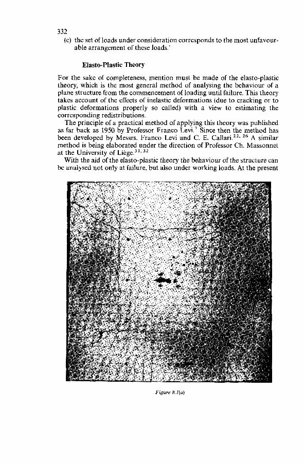
332 (c) the set of loads under consideration corresponds to the most unfavour-
able arrangement of these loads.’
Elasto-Plastic Theory
For the sake of completeness, mention must be made of the elasto-plastic theory, which is the most general method of analysing the behaviour of a plane structure from the commencement of loading until failure. This theory takes account of the effects of inelastic deformations (due to cracking or to plastic deformations properly so called) with a view to estimating the corresponding redistributions. The principle of a practical method of applying this theory was published
as far back as 1950 by Professor Franco Levi.’ Since then the method has been developed by Messrs. Franco Levi and C. E. 26 A similar method is being elaborated under the direction of Professor Ch. Massonnet at the University of Liège.31,32 With the aid of the elasto-plastic theory the behaviour of the structure can
be analysed not only at failure, but also under working loads. At the present
Figure 8.í(a)
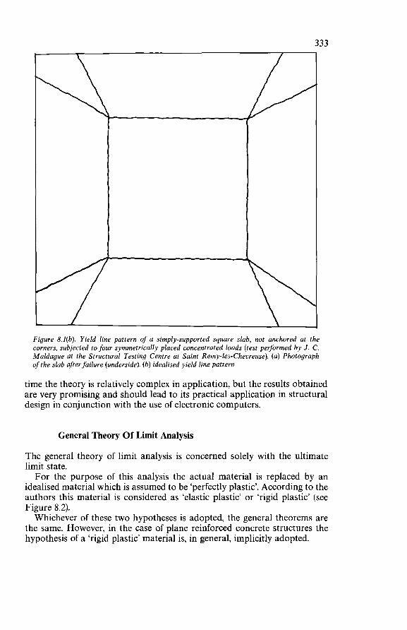
Figure 8.I(b). Yield line pattern of a simply-supported square slab, not anchored at the corners, subjected to four symmetrically placed concentrated loads (test performed by J. C. Maldugue at the Structural Testing Centre at Saint Remy-les-Chevreuse). (a) Photograph of the slab after failure (underside). (b) idealised yield line pattern
time the theory is relatively complex in application, but the results obtained are very promising and should lead to its practical application in structural design in conjunction with the use of electronic computers.
General Theory Of Limit Analysis
The general theory of limit analysis is concerned solely with the ultimate limit state. For the purpose of this analysis the actual material is replaced by an
idealised material which is assumed to be ‘perfectly plastic’. According to the authors this material is considered as ‘elastic plastic’ or ‘rigid plastic’ (see Figure 8.2). Whichever of these two hypotheses is adopted, the general theorems are
the same. However, in the case of plane reinforced concrete structures the hypothesis of a ‘rigid plastic’ material is, in general, implicitly adopted.
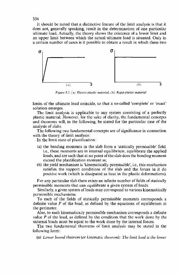
334 It should be noted that a distinctive feature of the limit analysis is that it
does not, generally speaking, result in the determination of one particular ultimate load, Actually, the theory shows the existence of a lower limit and an upper limit between which the actual ultimate load is situated. Only in a certain number of cases is it possible to obtain a result in which these two
U
(a) 3 Ibl 3
Figure 8.2. (a) Elastic-plastic material, (b) Rigid-plastic material
limits of the ultimate load coincide, so that a so-called ‘complete’ or ‘exact’ solution emerges. The limit analysis is applicable to any system consisting of a perfectly
plastic material. However, for the sake of clarity, the fundamental concepts and theorems will, in the following, be stated for the particular case of the analysis of slabs. The following two fundamental concepts are of significance in connection
with the theory of limit analysis: In the limit state of plastification: (a) the bending moments in the slab form a ‘statically permissible’ field,
i.e., these moments are in internal equilibrium, equilibrate the applied loads, and are such that at no point of the slab does the bending moment exceed the plastification moment m ;
(b) the yield mechanism is ‘kinematically permissible’, i.e., this mechanism satisfies the support conditions of the slab and the forces in it do positive work (which is dissipated as heat in the plastic deformations).
For any particular slab there exists an infinite number of fields of statically permissible moments that can equilibrate a given system of loads. Similarly, a given system of loads may correspond to various kinematically
permissible mechanisms. To each of the fields of statically permissible moments corresponds a
definite value P of the load, as defined by the equations of equilibrium at the perimeter. Also, to each kinematically permissible mechanism corresponds a definite
value P of the load, as defined by the condition that the work done by the external loads must be equal to the work done by the internal forces. The two fundamental theorems of limit analysis may be stated in the
following form: (a) Lower bound theorem (or kinematic theorem): The limit load is the lower
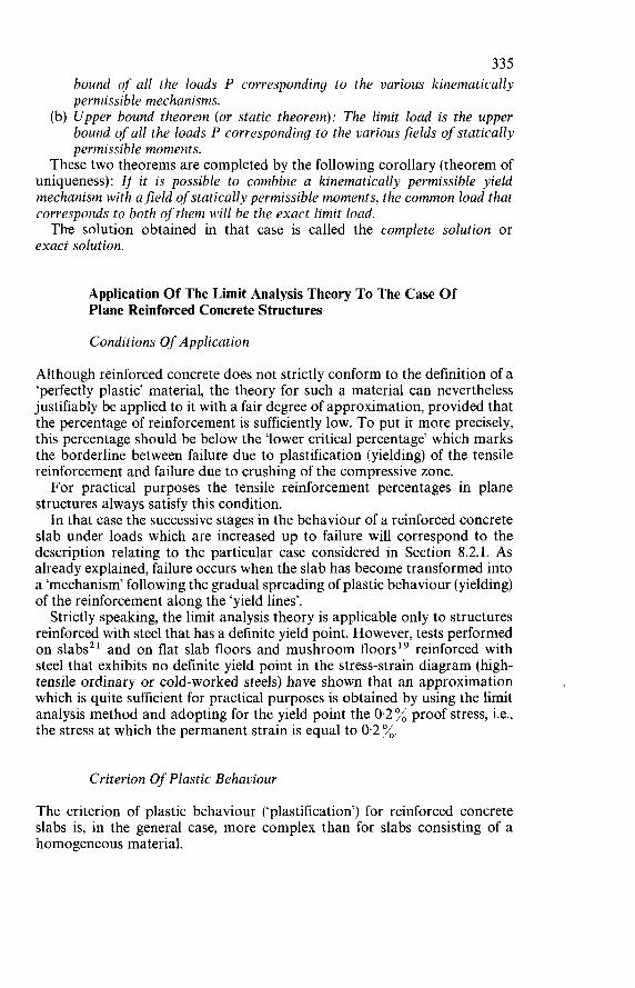
335 bound of all the loads P corresponding to the various kinematically permissible mechanisms.
(b) Upper bound theorem (or static theorem): The limit load is the upper bound of all the loads P corresponding to the various fields of statically permissible moments.
These two theorems are completed by the following corollary (theorem of uniqueness): If it is possible to combine a kinematically permissible yield mechanism with a-field of statically permissible moments, the common load that corresponds to both of them will be the exact limit load. The solution obtained in that case is called the complete solution or
exact solution.
Application Of The Limit Analysis Theory To The Case Of Plane Reinforced Concrete Structures
Conditions Of Application
Although reinforced concrete does not strictly conform to the definition of a ‘perfectly plastic’ material, the theory for such a material can nevertheless justifiably be applied to it with a fair degree of approximation, provided that the percentage of reinforcement is sufficiently low. To put it more precisely, this percentage should be below the ‘lower critical percentage’ which marks the borderline between failure due to plastification (yielding) of the tensile reinforcement and failure due to crushing of the compressive zone. For practical purposes the tensile reinforcement percentages in plane
structures always satisfy this condition. In that case the successive stages in the behaviour of a reinforced concrete
slab under loads which are increased up to failure will correspond to the description relating to the particular case considered in Section 8.2.1. As already explained, failure occurs when the slab has become transformed into a ‘mechanism’ following the gradual spreading of plastic behaviour (yielding) of the reinforcement along the ‘yield lines’. Strictly speaking, the limit analysis theory is applicable only to structures
reinforced with steel that has a definite yield point. However, tests performed on slabs” and on flat slab floors and mushroom floors” reinforced with steel that exhibits no definite yield point in the stress-strain diagram (high- tensile ordinary or cold-worked steels) have shown that an approximation which is quite sufficient for practical purposes is obtained by using the limit analysis method and adopting for the yield point the 0.2 % proof stress, i.e., the stress at which the permanent strain is equal to 0.2 %.
Criterion Of Plastic Behaviour
The criterion of plastic behaviour (‘plastification’) for reinforced concrete slabs is, in the general case, more complex than for slabs consisting of a homogeneous material.
336 As a rule, reinforced concrete slabs are provided with two layers of rein-
forcement, one of which is installed near the underside of the slab and is referred to as the positive reinforcement, while the other is installed near the top and is referred to as the negative reinforcement. Neither of these layers of reinforcement need necessarily be homogeneous
over the entire area of the slab, and each may comprise several different systems of reinforcement in different zones of the slab. For example, in the case of a slab continuous over its supports the layer of negative reinforcement will normally contain different percentages of reinforcement at the supports and in the mid-span region respectively. Similarly, the layer of positive reinforcement may contain different percentages at the centre of the slab and at the supports respectively. Hence it follows that the yield lines of the same algebraic sign, whether
negative or positive, will not necessarily be crossed by the same system of reinforcement. It may even occur that a given yield line will encounter different systems of reinforcement along its alignment. However, for the present purpose, it will be assumed that any particular yield line encounters only one system of reinforcement, though it should be noted that Jonesz3 has given a method of dealing with the case where a yield line encounters two different reinforcement systems. Furthermore, in the most general case, a system of reinforcement may
comprise bars extending in r arbitrary directions. Such a reinforcement system is called anisotropic. To each direction i of bars corresponds a resisting moment mi per unit width of the slab; this moment can be represented by a vector with a direction perpendicular to the direction i. The system is completely defined if the angles a,, az, . . . al . . . a, of the r directions of the bars in relation to a reference direction are given, together with the resisting moments m,, m2 ... mi ... m,. In the particular case where the system comprises only two orthogonal
(mutually perpendicular) directions of bars, it is called orthotropic. Finally, in the more restrictedly particular case where an orthotropic
system of reinforcement is so designed that the resisting moments in the two mutually perpendicular directions of the bars are equal, the system is called isotropic. A slab in which each of the two layers of reinforcement, top and bottom,
contains only one orthotropic system of reinforcement is itself called ortho- tropic if the bars in each direction in the top layer are parallel to the bars in each respective direction in the bottom layer. Furthermore, a slab in which each of the two layers contains only one isotropic system of reinforcement is itself called isotropic.
Criterion of ‘stepped‘ yielding (or ‘square’ yield criterion) (Johansen)
Consider a yield line segment crossed by a reinforcement system compris- ing bars in various directions 1, 2, 3 . . . i . . . r (see Figure 8.3). Suppose this to be positive yield line and let m,, m, . . . mi . . . m, denote the resisting moments per unit width corresponding to the various bar directions. These moments
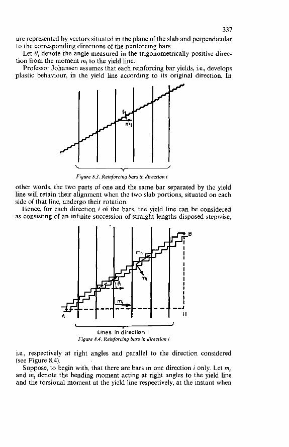
3 31 are represented by vectors situated in the plane of the slab and perpendicular to the corresponding directions of the reinforcing bars. Let Bi denote the angle measured in the trigonometrically positive direc-
tion from the moment mi to the yield line. Professor Johansen assumes that each reinforcing bar yields, i.e., develops
plastic behaviour, in the yield line according to its original direction. In
m
Y
Figure 8.3. Reinforcing bars in direction i
other words, the two parts of one and the same bar separated by the yield line will retain their alignment when the two slab portions, situated on each side of that line, undergo their rotation. Hence, for each direction i of the bars, the yield line can be considered
as consisting of an infinite succession of straight lengths disposed stepwise,
I Lines in direction i
Figure 8.4. Reinforcing bars in direction i
i.e., respectively at right angles and parallel to the direction considered (see Figure 8.4). Suppose, to begin with, that there are bars in one direction i only. Let m,,
and m, denote the bending moment acting at right angles to the yield line and the torsional moment at the yield line respectively, at the instant when
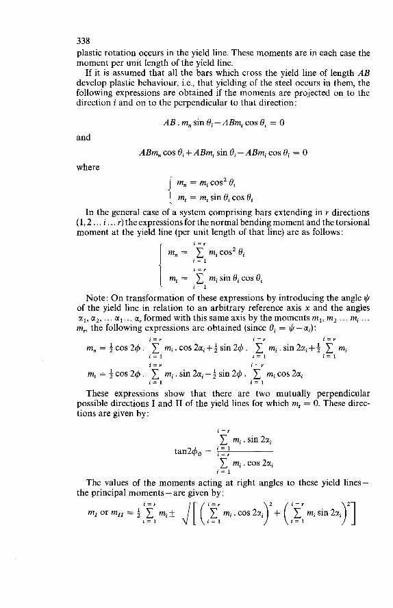
338 plastic rotation occurs in the yield line. These moments are in each case the moment per unit length of the yield line.
If it is assumed that all the bars which cross the yield line of length AB develop plastic behaviour, i.e., that yielding of the steel occurs in them, the following expressions are obtained if the moments are projected on to the direction i and on to the perpendicular to that direction:
AB. m, sin ûi - ABm, cos 8, = O and
ABm, cos ûi + ABm, sin Bi - ABm, cos Bi = O where
m, = mi cos2 Bi m, = mi sin Bi cos ûi
In the general case of a system comprising bars extending in r directions (1,2 . . . i.. . r) the expressions for the normal bending moment and the torsional moment at the yield line (per unit length of that line) are as follows:
m, = C micos2 ei m, = C misinBicos Bi
i = r
i = l i = r 1 i = 1
Note: O n transformation of these expressions by introducing the angle $ of the yield line in relation to an arbitrary reference axis x and the angles CI^, u2, . . . ... CI, formed with this same axis by the moments m,, m2 . . . mi . .. m,, the following expressions are obtained (since ûi = $-ai):
i = r i = r i = r
m, =+cos24. 1 mi.cos2ai++sin24. 1 mi.sin2cri++ C mi
m, =+cos24. 1 mi.sin2cri-+sin24. micos2cri
These expressions show that there are two mutually perpendicular possible directions I and II of the yield lines for which m, = O. These direc- tions are given by:
i = l i = l i = 1 i = r i = r
i = l i = l
i = r 1 mi. sin2ai tan24, =
1 mi.cos2ui i = l
The values of the moments acting at right angles to these yield lines-
m,orm,,=+ 1 mi& J[(iirmi.cos2CIi>’+( 1 misin2ui the principal moments - are given by :
)’I i = r i = r
i = 1 i = 1 i = l
I
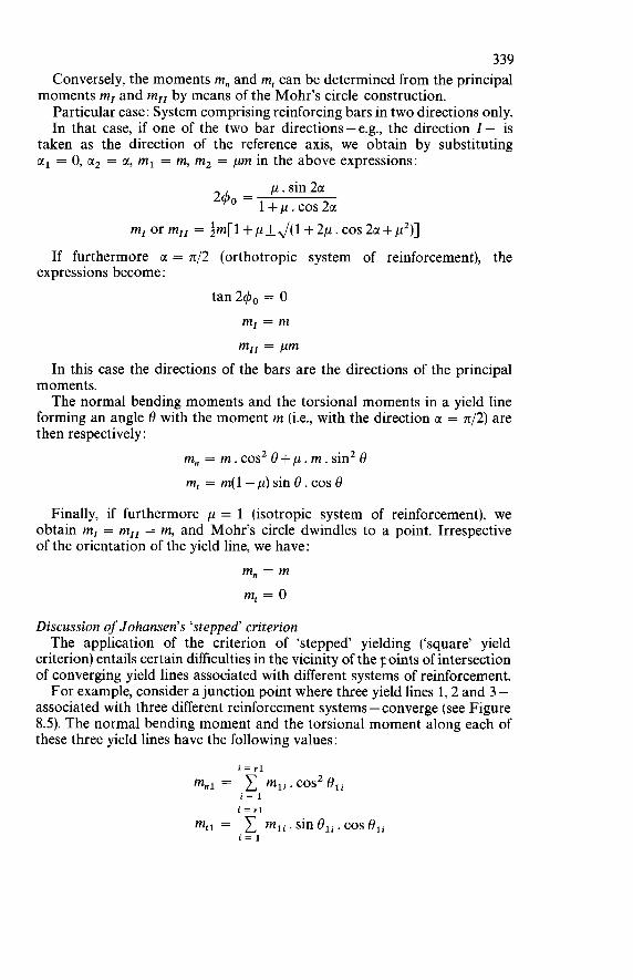
339 Conversely, the moments m, and m, can be determined from the principal
Particular case: System comprising reinforcing bars in two directions only. In that case, if one of the two bar directions-e.g., the direction i- is
taken as the direction of the reference axis, we obtain by substituting CI, = O, CI’ = CI, m, = m, m2 = pm in the above expressions:
moments m, and m,, by means of the Mohr’s circle construction.
p . sin CI 240 = l+p.cos2c!
m,orm,, = tm[l+p~+~(1+2p.c0~2~1+p’)] If furthermore CI = 4 2 (orthotropic system of reinforcement), the
expressions become: tan 240 = O
m, = m m,, = Pm
In this case the directions of the bars are the directions of the principal moments. The normal bending moments and the torsional moments in a yield line
forming an angle û with the moment m (i.e., with the direction CI = 742) are then respectively:
m, = m.cos2û+p.m.sin2û m, = m(1-p)sinû.cosû
Finally, if furthermore p = 1 (isotropic system of reinforcement), we obtain m, = m,, = m, and Mohr’s circle dwindles to a point. Irrespective of the orientation of the yield line, we have:
m, = m m, = O
Discussion of Johansen’s ‘stepped’ criterion The application of the criterion of ‘stepped’ yielding (‘square’ yield
criterion) entails certain difficulties in the vicinity of the p,oints of intersection of converging yield lines associated with different systems of reinforcement. For example, consider a junction point where three yield lines 1,2 and 3 -
associated with three different reinforcement systems -converge (see Figure 8.5). The normal bending moment and the torsional moment along each of these three yield lines have the following values :
i = r l
m,, = 1 mli.cos2eli i = 1
i = rl m,, = 1 mli . sin oli. cos eli
i = l
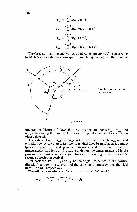
340 i = r2
mn2 = 1 m2i.cos2 ûzi
mt2 =
i = 1 i = r2 1 m,, . sin ûZi. cos
mn3 = 1 m3i. cos2 û3i mr3 = 1 m3i .sine3i.cosû3i
i = 1 i = r3
i = 1 i = r3
i = 1
The three normal moments m,,, m,, and mn3 completely define (according to Mohr’s circle) the two principal moments mi and m;, at the point of
-- Direction of principal moment m’,
3 Figure 8.5
intersection. Hence it follows that the torsional moments mnsl, mns2 and mns3 acting along the three yield lines at the point of intersection are com- pletely defined. The values of mnsl, mns2 and mns3 in terms of the moments m,,, mn2 and
mn3 will now be calculated. Let the three yield lines be numbered 1, 2 and 3 (proceeding in the usual positive trigonometrical direction of angular measurement) and let $12, $23 and $31 denote the angles (measured in the positive direction) between the yield lines corresponding to the first and the second subscript respectively. Furthermore, let pi, ß2 and ß3 be the angles (measured in the positive
direction) between the direction of the principal moment mi and the yield lines 1,2 and 3 respectively. The following relations can be written down (Mohr’s circle):
mi -k mi, mi - mi, 2 m,, =- 2 +- cos 2ß1
341
mn2 = m; + mi,
2 + m; - m;, 2 cos 2ß,
O n eliminating (m;+m;,)/2, (m;-m;,)/2 and ßi from the first four of the above equations, and bearing in mind that c$31 = 2 ~ - ( 4 ~ 2 + 4 1 3 ) , the expression for mnsl is obtained:
Similarly, the following are obtained:
The torsional moments mnsl, mns2 and mns3 are therefore completely
Hence, in the general case: determined in terms of m,,, mn2 and mn3.
mns1 f mt, mnr2 + mt2 mns3 f mí3 i = r
where m,,, mt2 and mt3 represent the values of 1 mi sin ûi cos ûi at each of Consequently, Johansen’s theorem of ‘stepped’ yielding does not apply
at the point of intersection. Only in the special case where the three converging yield lines are asso-
ciated with the same reinforcement system (i.e., the principal moments m; and mi, at the intersection coincide with the principal moments m, and m,, of the common system) do the following relations apply:
mns1 = mt, mns2 = mt2 mns3 = 4 3
the three yield lines. i = 1
342 In this special case Johansen’s criterion of yielding is therefore satisfied
at the point of intersection. In the general case the difficulty arising from the non-fulfilment of this
criterion at the intersections of yield lines can be resolved by two different solutions, which will be explained in the following: First solution: Retention of Johansen’s criterion. Concept of ‘disturbed zones Johansen’s criterion is retained for those parts of the yield lines which are
not close to a junction point. The moments at a yield line 1 are therefore: normal bending moment :
i = rl m,, = 1 mlicos2 eli
i = 1
torsional moment:
Furthermore, in
i = rl m,, = 1 mli . sin eli . cos eli
i = 1
the vicinity of a junction point of yield lines there is assumed to exist a very small disturbed zone in which Johansen’s criterion is not satisfied. This disturbed zone is taken into account by introducing for each of the yield lines 1, 2 and 3 an additional torsional moment at the junction point. These torsional moments have the following values :
mnsl -mtl for yield line 1 mnS2 - mi2 for yield line 2 mnS3 - mt3 for yield line 3
This first solution is the one which was adopted implicitly by Johansen’ and Jones,21 and explicitly by NielsenZ2 Solution solution: Adoption of the ‘normal‘ criterion
moment is specified, namely : It is assumed that over the entire length of a yield line only the normal
i = rl m,, = 1 mli .cos2 ûli
i = l
The difference in relation to Johansen’s criterion is that now the torsional moment mnsl at a yield line may have any value. On the basis of this criterion the intersections of yield lines present no
problem at all because the torsional moments mns which occur there can be given the values obtained from Mohr’s circle construction.
‘i Lo jecond solution, which has been adopted more particularly by Kemp and Morley,23 appears to be in not so good agreement with reality, since the ‘disturbed’ zones do indeed correspond to actual observations. Tests show that in the immediate vicinity of yield line junction points there are in fact such ‘disturbed zones where the converging lines ramify so that there is, strictly speaking, no true ‘point of intersection’. However, the concept of ‘disturbed zone’ does not readily lend itself to
mathematical treatment. If the hypothesis of straight yield lines, which is the basis of the simple method of analysis embodying Johansen’s theory, is to
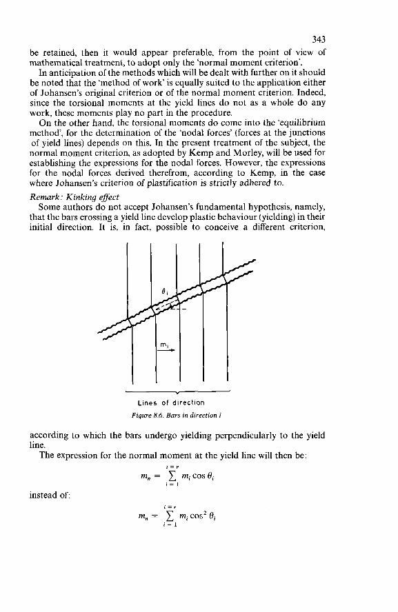
343 be retained, then it would appear preferable, from the point of view of mathematical treatment, to adopt only the ‘normal moment criterion’. In anticipation of the methods which will be dealt with further on it should
be noted that the ‘method of work is equally suited to the application either of Johansen’s original criterion or of the normal moment criterion. Indeed, since the torsional moments at the yield lines do not as a whole do any work, these moments play no part in the procedure. On the other hand, the torsional moments do come into the ‘equilibrium
method’, for the determination of the ‘nodal forces’ (forces at the junctions of yield lines) depends on this. In the present treatment of the subject, the normal moment criterion, as adopted by Kemp and Morley, will be used for establishing the expressions for the nodal forces. However, the expressions for the nodal forces derived therefrom, according to Kemp, in the case where Johansen’s criterion of plastification is strictly adhered to. Remark: Kinking effect Some authors do not accept Johansen’s fundamental hypothesis, namely,
that the bars crossing a yield line develop plastic behaviour (yielding) in their initial direction. It is, in fact, possible to conceive a different criterion,
Y
Lines of direction Figure 8.6. Bars in direction i
according to which the bars undergo yielding perpendicularly to the yield line. The expression for the normal moment at the yield line will then be:
i = r
m, = micosei i = 1
instead of:
m, = 1 mi cos2 ei i = 1
344 The value of the normal moment that emerges from this hypothesis as
to the ‘kinking effect’ of the bars is higher than the value of the normal moment corresponding to Johansen’s hypothesis. It would appear that the behaviour in reality is somewhere between these
two hypotheses. Basing himself on tests carried out at the University of Wales, Swansea, Kwiecinski has formulated a criterion in which account is taken of the ‘partial kinking’ of the bars and whose results are intermediate between those emerging from Johansen’s criterion and from the criterion of ‘total kinking’ respectively (cf. refs 24, 25, 27). Kwiecinski’s tests as well as the tests performed by Sozen and Lemschow show that the adoption of a ‘total kinking’ criterion would not be on the safe side. O n the other hand, it would appear that Johansen’s criterion gives normal bending moments that are smaller than the actual moments in all the cases investigated and is therefore on the safe side. This conclusion is confirmed by the first results of the systematic research
which has been undertaken by Massonnet at the University of Liège with a view to arriving at the direct experimental determination of the criterion for failure by simple bending in reinforced concrete slabs. The tests already performed have indeed shown that by applying Johansen’s criterion the results obtained are on the safe side in relation to the experimentally determined results.
Yield Line Method
The so-called ‘yield line method’, which was introduced by Ingerslev and developed by K. W. Johansen in his doctorate thesis in 1943,3 embodies the practical application of the kinematic theorem (lower bound theorem) to reinforced concrete structures. For a given plane structure this theory results in the determination of a load P which is larger than, or equal to, the actual ultimate load. If the kinematically permissible mechanism adopted is the precise failure mechanism, then this load P will indeed be equal to the ultimate load. In order to be certain that this last-mentioned condition is satisfied, it is
necessary (in the absence of direct experimental verification) to be able to determine, for the plane structure under consideration, a field of statically permissible moments giving the same limit load P. Only in that case is it possible to assert - on the basis of the theorem of uniqueness - that the load P is the exact ultimate load. Unfortunately, at the present time only a small number of exact or com-
plete solutions (i.e., in which a kinematically permissible mechanism occurs in conjunction with a statically permissible field of moments so that both conditions give the same limit load) are available. These solutions correspond only to slabs of the simplest shapes. Some known complete solutions are indicated in Section 8.4. In the next section (Section 8.3) the yield line method of Johansen will be
outlined. For the purpose of practical application of the method it will, however, be necessary to consult publications giving a fuller treatment of
345 the subject, including more particularly Professor K. W. Johansen’s book3 and the publications of Steinmann,” Wood,I2 Massonnet16 and Jones.14 Reference may also be made to ‘Recent developments in yield line theory’ published by the Cement and Concrete Association, May 1965.23
8.3 YIELD LINE THEORY
8.3.1 PRINCIPLES OF THE THEORY
The yield line theory assumes that reinforced concrete can be considered as a rigid-plastic material. In the ultimate limit state the elastic deformations of the various elements of the mechanism are therefore neglected in relation to the plastic deformations. The failure mechanism thus comprises plane rigid elements whose junctions are formed by so-called yield lines, or ‘fracture lines’, functioning as linear hinges, at which the plastic deformations are concentrated. The deformations of the structure are due solely to the rotations of these
rigid constituent elements about axes that are compatible with the support conditions. The deformed surface is of a polyhedral shape (or possibly a ruled surface in certain zones). As indicated earlier, it is assumed that the normal bending moment at a
yield line crossed by a reinforcement system comprising bars disposed in the directions 1, 2 ... i ... i-, to which correspond the resisting moments m,, m, ... mi .. . m,, has the value:
i = r
m, = micos2 ei i = 1
The torsional moment at the yield line is not specified (cf. above 2nd
The application of the yield line theory comprises two successive stages: The first stage consists in determining the various types of possible
mechanisms, having regard to the shape of the slab, the support conditions and the loading. Each type of mechanism thus defined should of course be compatible with the conditions of restraint of the structure. In this way various ‘families’ of possible mechanisms can be defined, each
of these families being dependent upon p geometrical parameters x,, x2 . . . x,. The second stage consists in seeking, for each of the families defined, the
particular mechanism that gives the lowest limit load value. This mechanism, determined by particular values of the parameters xl, x2 ... p, constitutes the ‘best’ mechanism for the family of possible mechanisms under consideration. This procedure of seeking the ‘best’ mechanism is based on considering the
conditions of equilibrium of the various rigid elements of which the mechanism is composed. For practical purposes two methods can be applied. The first consists in
expressing the equilibrium conditions in an overall form for the slab as a whole by applying the equation of work. O n the assumption that the ratios
solution : Adoption of the normal criterion).
346 of the various resisting moments of the slab to one of them-called the ‘reference resisting moment’ and designated by m - have been determined in advance by the designer, the load P is thus obtained in the form of a function of the p geometrical parameters of the mechanism and the reference resisting moment m (or, alternatively, the moment m is obtained as function of the p geometrical parameters and the load P). Next, the values of the p parameters must be sought which make the function P (xi, x2 ... x,, m) a minimum or, what comes to the same thin? uliich make the function m (xl, x2 ... x,, P) a maximum. The second method consists in expressing the conditions of equilibrium
of each of the n rigid elements that constitute the mechanism. In applying this method it is necessary to take into account the ‘nodal forces’ which are statically equivalent to the shear forces and torsional moments acting at the yield lines. One each of the ultimate loads that corresponds to the ‘best’ mechanism
of each family envisaged has been obtained by applying either of the two methods indicated above, the ‘best’ mechanism for the whole of these families can be deduced therefrom. The corresponding load is adopted as the upper bound of the limit load (cf. lower bound theorem).
It should be borne in mind that we can be certain that this load is the exact limit load only if it is possible to find a field of statically permissible moments, in the slab as a whole, which results in an equal load (cf. theorem of uniqueness).
8.3.2 FINDING A P R O B A B L E F A I L U R E MECHANISM
The procedure for this is based on the application of the followine theorems, which result from the fundamental hypothesis concerning the concentration of the deformations at the yield lines.
Theorem 1: The yield line between the two rigid elements of a slab passes through the point of intersection of their respective axes of rotation. Hence it follows that, if the element considered is supported along one
of its edges, the axis of rotation will coincide with the line of support. For a slab element resting on a point support the axis rotation will pass through that support. By applying this theorem it is possible completely to determine the yield
line pattern if the rotations Bi of the various slab elements are known. In the ultimate limit state the structure is transformed into a ‘mechanism’, and if the yield line pattern has been established, the angles of rotation Bi of the various elements will be defined, except for a common factor. Reciprocally :
Theorem 2: If the axes of rotation of the various rigid elements of the slab and the ratios of the various angles of rotation ûi to any one of these are given, the yield line pattern is compìetely determined.
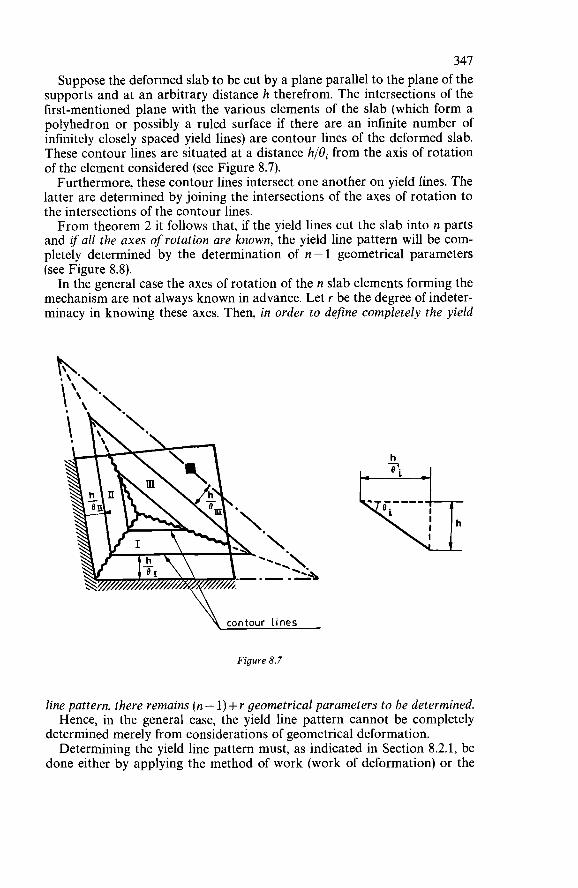
347 Suppose the deformed slab to be cut by a plane parallel to the plane of the
supports and at an arbitrary distance h therefrom. The intersections of the first-mentioned plane with the various elements of the slab (which form a polyhedron or possibly a ruled surface if there are an infinite number of infinitely closely spaced yield lines) are contour lines of the deformed slab. These contour lines are situated at a distance h/ûi from the axis of rotation of the element considered (see Figure 8.7). Furthermore, these contour lines intersect one another on yield Iines. The
latter are determined by joining the intersections of the axes of rotation to the intersections of the contour lines. From theorem 2 it follows that, if the yield lines cut the slab into n parts
and if all the axes ofrotation are known, the yield line pattern will be com- pletely determined by the determination of n - 1 geometrical parameters (see Figure 8.8). In the general case the axes of rotation of the n slab elements forming the
mechanism are not always known in advance. Let r be the degree of indeter- minacy in knowing these axes. Then, in order to define completely the yield
\ contour iines
Figure 8.7
line pattern, there remains (n - 1) + r geometrical parameters to be determined. Hence, in the general case, the yield line pattern cannot be completely
determined merely from considerations of geometrical deformation. Determining the yield line pattern must, as indicated in Section 8.2.1, be
done either by applying the method of work (work of deformation) or the
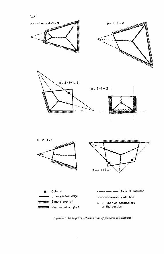
348 p = n - 1 + r = 4-1
.€-
Column ------ Axis of rotation - Unsupported edge -MIC~~-.C.LH Yield line
Simple support D Number of parameters Restrained support of the section
Figure 8.8. Example of determination of probable mechanisms
349 method of nodal forces (equilibrium of the rigid elements of the slab). These two methods are explained in Sections 8.3.3 and 8.3.4.
8.3.3 APPLICATION OF THE METHOD OF W O R K
Suppose that a family of possible mechanisms, depending upon p geometrical parameters xl, x2, . . . xp, has been determined on the basis of the conditions of deformation. Consider a conveniently chosen point of the slab and suppose that this point is given a displacement 6 compatible with the restraints to which the slab is subject. The equation of work is obtained by equating the work done by the
external forces to the work done by the internal forces in bringing about the displacement under consideration. O n the assumption that the mech- anism comprises only the straight yield lines,* this equation can be written as follows :
CPihi + jjpj. hj. dx . dy = lm, . a. ds where :
di = displacement of a concentrated force Pi hj = displacement of a distributed force pj per unit area a = rotation at a yield line m, = normal bending moment at a yield line per unit length
The displacements di and dj as well as the rotations o! are all expressed in terms of 6, which occurs as a factor on both sides of the equation and is therefore cancelled out. The normal moments m, are known in terms of the resisting moments of
the different directions of the reinforcing bars in the layer corresponding to the yield line considered. Suppose that the ratios of the various positive and negative resisting moments of the slab reinforcement to one of them -called the ‘reference moment’ (m) - is determined in advance by the designer. That being so, the equation of work will give a relation between the total load P, the ‘reference moment’ m, and the p geometrical parameters relating to the family under consideration. P is therefore given by a function P (xl, x2 ... xp, m) or, alternatively,
m is given by a function m (x~, x2 . . . xp, P). The next step consists in determining the values of the p geometrical
parameters which make the function P a minimum or, what amounts to the same thing, make the function m a maximum. This determination can be done either by successive numerical approximations or by solving one of the following two sets of equations:
dm - = o - = o ap 8x1 ax 1
*The case of fan-type mechanisms cannot be dealt with in this short treatment of the subject. For this it will be necessary to consult the literature (more particularly refs. 3 and 12).
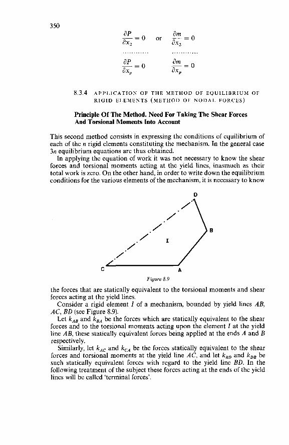
3 50
8.3.4 APPLICATION OF THE METHOD OF EQUILIBRIUM OF RIGID ELEMENTS (METHOD OF NODAL FORCES)
Principie Of The Method. Need For Taking The Shear Forces And Torsional Moments Into Account
This second method consists in expressing the conditions of equilibrium of each of the II rigid elements constituting the mechanism. In the general case 3n equilibrium equations are thus obtained. In applying the equation of work it was not necessary to know the shear
forces and torsional moments acting at the yield lines, inasmuch as their total work is zero. O n the other hand, in order to write down the equilibrium conditions for the various elements of the mechanism, it is necessary to know
D
Figure 8.9
the forces that are statically equivalent to the torsional moments and shear forces acting at the yield lines. Consider a rigid element i of a mechanism, bounded by yield lines AB,
AC, BD (see Figure 8.9). Let k,, and k,, be the forces which are statically equivalent to the shear
forces and to the torsional moments acting upon the element í at the yield line AB, these statically equivalent forces being applied at the ends A and B respectively. Similarly, let kAc and k,, be the forces statically equivalent to the shear
forces and torsional moments at the yield line AC, and let k,, and k,, be such statically equivalent forces with regard to the yield line BD. In the following treatment of the subject these forces acting at the ends of the yield lines will be called ‘terminal forces’.
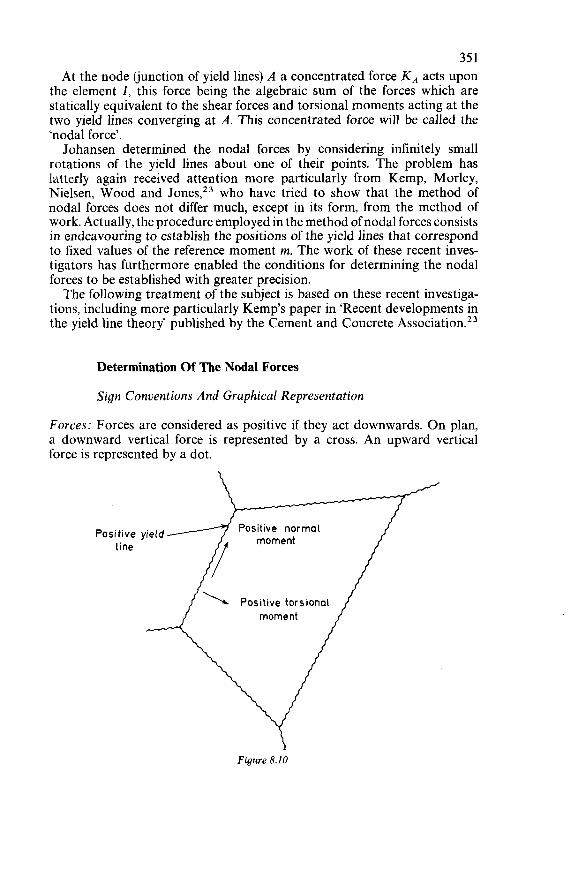
351 At the node Cjunction of yield lines) A a concentrated force KA acts upon
the element I, this force being the algebraic sum of the forces which are statically equivalent to the shear forces and torsional moments acting at the two yield lines converging at A. This concentrated force will be called the ‘nodal force’. Johansen determined the nodal forces by considering infinitely small
rotations of the yield lines about one of their points. The problem has latterly again received attention more particularly from Kemp, Morley, Nielsen, Wood and Jones,23 who have tried to show that the method of nodal forces does not differ much, except in its form, from the method of work. Actually, the procedure employed in the method of nodal forces consists in endeavouring to establish the positions of the yield lines that correspond to fixed values of the reference moment m. The work of these recent inves- tigators has furthermore enabled the conditions for determining the nodal forces to be established with greater precision. The following treatment of the subject is based on these recent investiga-
tions, including more particularly Kemp’s paper in ‘Recent developments in the yield line theory’ published by the Cement and Concrete Ass~ciation.~~
Determination Of The Nodal Forces
Sign Conventions And Graphical Representation
Forces: Forces are considered as positive if they act downwards. O n plan, a downward vertical force is represented by a cross. An upward vertical force is represented by a dot.
Positive normal moment Positive yield
line
Figure 8.10
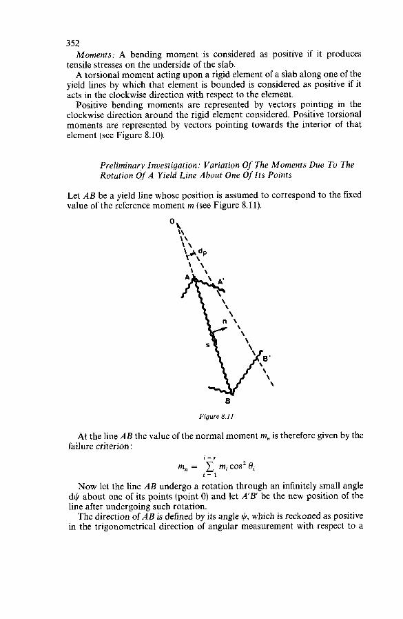
352 Moments: A bending moment is considered as positive if it produces
tensile stresses on the underside of the slab. A torsional moment acting upon a rigid element of a slab along one of the
yield lines by which that element is bounded is considered as positive if it acts in the clockwise direction with respect to the element. Positive bending moments are represented by vectors pointing in the
clockwise direction around the rigid element considered. Positive torsional moments are represented by vectors pointing towards the interior of that element (see Figure 8.10).
Preliminary Investigation: Variation Of The Moments Due To The Rotation Of A Yield Line About One Of Its Points
Let AB be a yield line whose position is assumed to correspond to the fixed value of the reference moment m (see Figure 8.11).
8’ \ \ \
8
Figure 8.11
At the line AB the value of the normal moment m, is therefore given by the failure criterion :
i = r
m, = 1 mi cos’ Bi i = 1
Now let the line AB undergo a rotation through an infinitely small angle d$ about one of its points (point O) and let A’B’ be the new position of the line after undergoing such rotation. The direction of AB is defined by its angle I), which is reckoned as positive
in the trigonometrical direction of angular measurement with respect to a
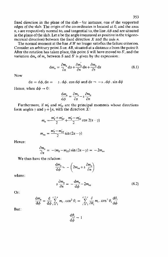
353 fixed direction in the plane of the slab-for instance, one of the supported edges of the slab. The origin of the co-ordinates is located at O, and the axes n, s are respectively normal to, and tangential to, the line AB and are situated in the plane of the slab. Let a be the angle (measured as positive in the trigono- metrical direction) between the fixed direction X and the axis n. The normal moment at the line A'B' no longer satisfies the failure criterion.
Consider an arbitrary point S on AB, situated at a distance s from the point O. After the rotation has taken place, this point S will have moved to S', and the variation dm, of m, between S and S' is given by the expression:
Now da = d4,dn = -s.d4.cosd+andds = -s.d$.sind4
dm, am, am, d4 aa an
Hence, when d4 -f O:
S- __ - ~- -
Furthermore, if m; and mir are the principal moments whose directions form angles y and y +$n, with the direction X:
m; - m;+m;, I m,=- I cos 2(a - y) 2 2
mi - m;, 2 mns = ~ sin (2a- y)
Hence :
W e thus have the relation:
where :
Or :
But:
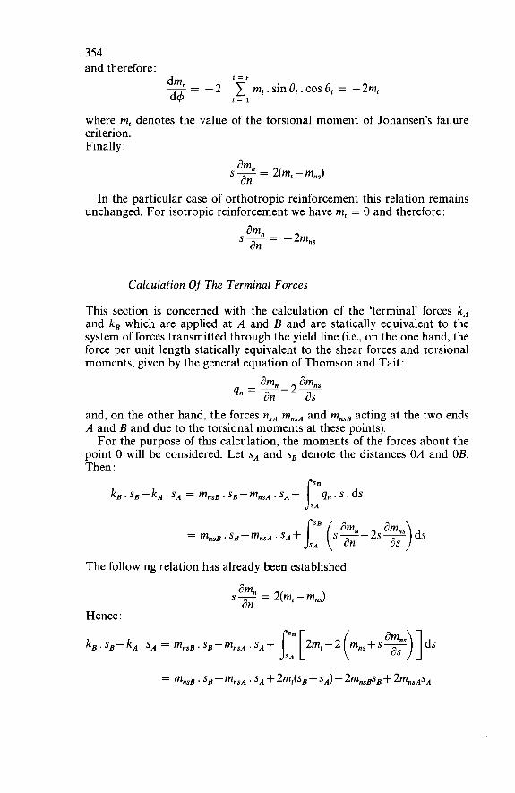
354 and therefore :
i = r
d4 i = 1 = -2 mi.sinûi.cosOi = -2m, dm,
where m, denotes the value of the torsional moment of Johansen's failure criterion. Finally :
am" an s - = 2(m, - m,,)
In the particular case of orthotropic reinforcement this relation remains unchanged. For isotropic reinforcement we have m, = O and therefore:
Calculation Of The Terminal Forces
This section is concerned with the calculation of the 'terminal' forces k, and k, which are applied at A and B and are statically equivalent to the system of forces transmitted through the yield line (i.e., on the one hand, the force per unit length statically equivalent to the shear forces and torsional moments, given by the general equation of Thomson and Tait:
and, on the other hand, the forces nSA mnsA and mnsB acting at the two ends A and B and due to the torsional moments at these points). For the purpose of this calculation, the moments of the forces about the
point O will be considered. Let sA and s, denote the distances 0.4 and OE. Then :
The following relation has already been established
am, s - = 2(m, - mns) an Hence :
k,.s,-kA.sA = mnsB.sB-mnsA.sA+ 2m,-2 m,,+s- s::[ ( aA.)]ds
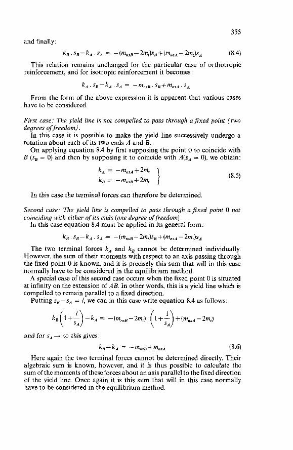
355 and finally :
kB . SB - k, . SA = - (m,,, - 2m,)S~ + ( IT,,,A - 2m,)S~ (8.4) This relation remains unchanged for the particular case of orthotropic
reinforcement, and for isotropic reinforcement it becomes :
k, . SB-kA. SA = -mnsB. Sg+mns~. SA
From the form of the above expression it is apparent that various cases have to be considered.
First case: The yield line is not compelled to pass through afixed point (two degrees of freedom). In this case it is possible to make the yield line successively undergo a
rotation about each of its two ends A and B. O n applying equation 8.4 by first supposing the point O to coincide with
B (se = O) and then by supposing it to coincide with A(sA = O), we obtain: k, = -mnsA+2mt kB = -mnsB+2mt
In this case the terminal forces can therefore be determined.
Second case: The yield line is compelled to pass through afixed point O not coinciding with either of its ends (one degree of freedom) In this case equation 8.4 must be applied in its general form:
k, . sB - kA . SA = - (mnsB - 2m,)sB + (mnsA - 2mt)sA The two terminal forces kA and k, cannot be determined individually.
However, the sum of their moments with respect to an axis passing through the fixed point O is known, and it is precisely this sum that will in this case normally have to be considered in the equilibrium method. A special case of this second case occurs when the fixed point O is situated
at infinity on the extension of AB. In other words, this is a yield line which is compelled to remain parallel to a fixed direction. Putting sB - S, = 1, we can in this case write equation 8.4 as follows :
and for s, + m this gives:
kB-kA = -mnsB+mnsA (8.6) Here again the two terminal forces cannot be determined directly. Their
algebraic sum is known, however, and it is thus possible to calculate the sum of the moments of these forces about an axis parallel to the fixed direction of the yield line. Once again it is this sum that will in this case normally have to be considered in the equilibrium method.
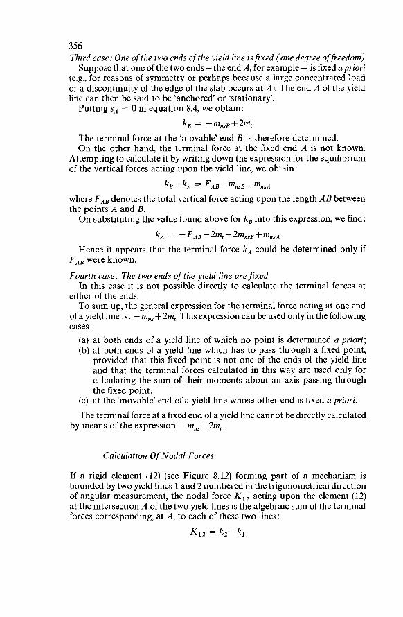
356 Third case: One ofthe two ends of the yield line isfixed (one degree offeedom) Suppose that one of the two ends - the end A, for example - is fixed a priori
(e.g., for reasons of symmetry or perhaps because a large concentrated load or a discontinuity of the edge of the slab occurs at A). The end A of the yield line can then be said to be ‘anchored’ or ‘stationary’. Putting S, = O in equation 8.4, we obtain:
k, = -mnsB+2m, The terminal force at the ‘movable’ end B is therefore determined. O n the other hand, the terminal force at the fixed end A is not known.
Attempting to calculate it by writing down the expression for the equilibrium of the vertical forces acting upon the yield line, we obtain:
kB - kA = + mnsB - mnsA where FA, denotes the total vertical force acting upon the length AB between the points A and B. On substituting the value found above for k, into this expression, we find:
kA = -FA, + 2m, - 2mnsB + mnsA Hence it appears that the terminal force k, could be determined only if
FA, were known. Fourth case: The two ends of the yield line are fixed In this case it is not possible directly to calculate the terminal forces at
either of the ends. To sum up, the general expression for the terminal force acting at one end
of a yield line is : - m,, + 2m,. This expression can be used only in the following cases : (a) at both ends of a yield line of which no point is determined a priori; (b) at both ends of a yield line which has to pass through a fixed point,
provided that this fixed point is not one of the ends of the yield line and that the terminal forces calculated in this way are used only for calculating the sum of their moments about an axis passing through the fixed point;
(c) at the ‘movable’ end of a yield line whose other end is fixed a priori. The terminal force at a fixed end of a yield line cannot be directly calculated
by means of the expression - mns + 2m,.
Calculation Of Nodal Forces
If a rigid element (12) (see Figure 8.12) forming part of a mechanism is bounded by two yield lines 1 and 2 numbered in the trigonometrical direction of angular measurement, the nodal force K,, acting upon the element (12) at the intersection A of the two yield lines is the algebraic sum of the terminal forces corresponding, at A, to each of these two lines:
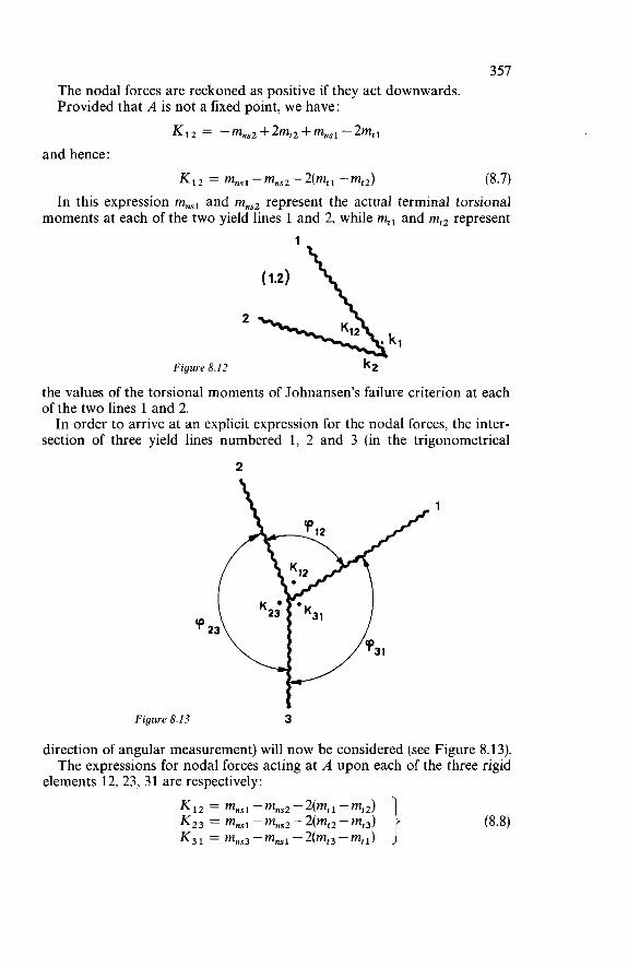
357 The nodal forces are reckoned as positive if they act downwards. Provided that A is not a fixed point, we have:
Ki2 = -mns2+2mt2+mnsi-2mtt and hence :
Ki2 = mnsi -mnsZ-2(mrt -mt2) (8.7) In this expression mnsl and mns2 represent the actual terminal torsional
moments at each of the two yield lines 1 and 2, while m,, and mt2 represent
2
Figure 8.12 k2
the values of the torsional moments of Johnansen’s failure criterion at each of the two lines 1 and 2. In order to arrive at an explicit expression for the nodal forces, the inter-
section of three yield lines numbered 1, 2 and 3 (in the trigonometrical
2
Figure 8.13 3
direction of angular measurement) will now be considered (see Figure 8.13). The expressions for nodal forces acting at A upon each of the three rigid
elements 12, 23, 31 are respectively:
(8.8) Ki2 = mnsi-mns2-2(mti -mi21 K 2 3 = mnsl - mns2 - 2(mr2 - mt3) K, i = mns3 - mnsi - 2(mt, - mti)
358 mnsl, mns2 and mns3 can be replaced by their values calculated in Section namely :
8.2.2
(8.9)
Note 1: Equations 8.9 are not identical with the expressions for the nodal forces given by Johansen’ or Jones.21 The reason for this is that those authors adopt Johansen’s ‘stepped’ criterion of yielding (as defined in Section 8.2.2), according to which a constant bending moment m, and a constant torsional moment m, act at the yield line, namely:
i - * i = r
m, = 1 mi cos2 ûi and m, = mi sin Bi cos Bi i = 1 i = l
Now equations 8.9 are based on the assumption of the criterion for the normal moment:
i = r
mn = 1 mi cos2 ûi i = 1
while the torsional moment is not specified. Using these expressions therefore presupposes that, on writing down the equilibrium equations for the rigid elements of the mechanism, the torsional moment m, embodied in Johansen’s failure criterion is not taken into account. For practical purposes it is more convenient to write the equilibrium
equations with due regard not only to the normal moment mn but also to the torsional moment m, of Johansen’s failure criterion. Consider a yield line forming an angle ß with the axis of rotation of the
corresponding rigid element (see Figure 8.14) Suppose that the yield line AB corresponds to an orthotropic reinforce-
ment system with principal moments m and ,um. Let CI be the angle that the moment m forms with the axis of rotation of the element. First of all we shall use the criterion of the normal moment. The normal moment at the yield line, per unit length, is:
mn = m cos2(ß - CI)+ ,um sin2 (ß - CI) The component of this moment with respect to the axis of rotation is:
[m cos’ (b - CI)+ ,um sin2(ß - CI)] sin ß
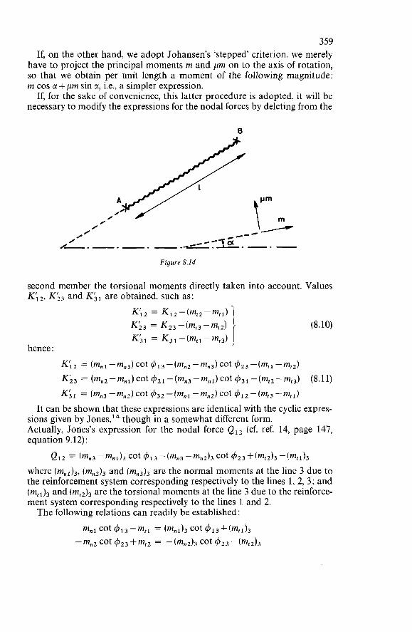
359 If, on the other hand, we adopt Johansen’s ‘stepped’ criterion, we merely
have to project the principal moments rn and prn on to the axis of rotation, so that we obtain per unit length a moment of the following magnitude: rn cos a + prn sin a, i.e., a simpler expression.
If, for the sake of convenience, this latter procedure is adopted, it will be necessary to modify the expressions for the nodal forces by deleting from the
0
Figure 8.14
second member the torsional moments directly taken into account. Values Ki2, KL3 and Ki, are obtained, such as:
hence :
(8.10)
2 = (%l- cot 41 3 - ( m n 2 - mn3) cot 4 2 3 -(rntl - rnrZ) K23 = (mn2 -rnni) cot 4 2 I - (mn3 -mní) cot 4 3 1 - (rnrz - mt3) Ki, = (mn3 -mn2)cot 43z-(mn, -rnn,)cot4,z-(mr,-m,,)
(8.11)
It can be shown that these expressions are identical with the cyclic expres- sions given by Jones,I4 though in a somewhat different form. Actually, Jones’s expression for the nodal force Q12 (cf. ref. 14, page 147, equation 9.12):
QI 2 = (mn3 -mn1)3 cot $1 3 -(mn3 -rnn2)3 cot 4 2 3 + (rnt2)3 -(fflf 1)3
where (m,,),, (mn2)3 and (rnn3)3 are the normal moments at the line 3 due to the reinforcement system corresponding respectively to the lines 1, 2, 3; and (m,,), and (rnt2)3 are the torsional moments at the line 3 due to the reinforce- ment system corresponding respectively to the lines 1 and 2. The following relations can readily be established :
mm1 cot 413-mtl = (%1)3 cot 413+(rnt1)3 -rnn2 cot 423+mt2 = -(rnn2)3 cot 423-(‘f2)3
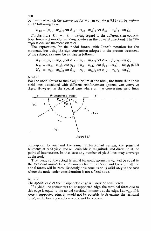
360 by means of which the expression for K;, in equation 8.11 can be written in the following form:
K;2 = (%1-%3)3 cot 613-(mn2-mn3)3 cot 423+(mt1)3-(mt2)3 Furthermore: K12 = -Q12, having regard to the different sign conven-
tion (Jones reckons Q12 as being positive in the upward direction). The two expressions are therefore identical. The expressions for the nodal forces, with Jones’s notation for the
moments, but using the sign convention adopted in the present treatment of the subject, can now be written as follows:
K I 2 = (mn1-mn3)3 cot 613-(mn2-mn3)3 cot 623+(mt1)3-(me2)3 K;3 = (mn2-mnl)i cot 621-(mn3-mn1)1 cot 6 3 1 +(mt2)1-(mt3)1(8.12)
= (mn3-mn2)2 cot 632-(mn1-mn2)2 cot 612+(mt3)2-(mti)2
Note 2: For the nodal forces to make equilibrium at the node, not more than three yield lines associated with different reinforcement systems can converge there. However, in the special case where all the converging yield lines
e Unsupported edge e
(2e)
Figure 8.15
correspond to one and the same reinforcement system, the principal moments at each yield line will coincide in magnitude and direction at the point of intersection. In that case any number of yield lines may converge at the node. That being so, the actual terminal torsional moments mns will be equal to
the torsional moments of Johansen’s failure criterion and therefore all the nodal forces will be zero. Evidently, this conclusion is valid only in the case where the node under consideration is not a fixed node.
Note 3: The special case of the unsupported edge will now be considered. If a yield line encounters an unsupported edge, the terminal force due to
this edge is equal to the actual torsional moment at the edge, i.e., mnse. If it were a supported edge, it would not be possible to determine the terminal force, as the bearing reaction would not be known.
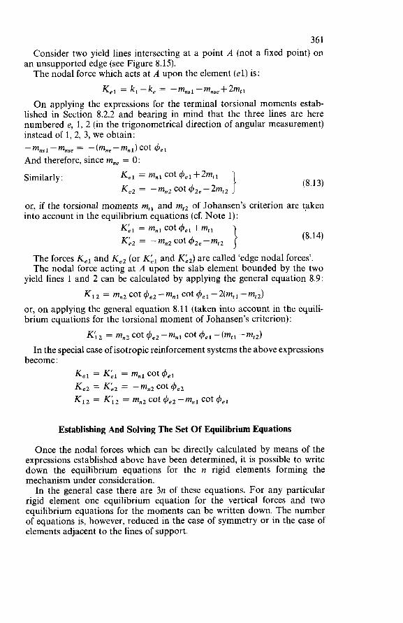
361 Consider two yield lines intersecting at a point A (not a fixed point) on
The nodal force which acts at A upon the element (el) is: an unsupported edge (see Figure 8.15).
K,, = k,-k, = -mnsl-mnse+2m,, O n applying the expressions for the terminal torsional moments estab-
lished in Section 8.2.2 and bearing in mind that the three lines are here numbered e, 1, 2 (in the trigonometrical direction of angular measurement) instead of 1, 2, 3, we obtain:
And therefore, since mne = O: -mnsi-mnse = -(mne-mni)COt 4 e i
Similarly : (8.13)
or, if the torsional moments m,, and m,, of Johansen’s criterion are taken into account in the equilibrium equations (cf. Note 1):
(8.14) 1 Keí = mní cot 4 e i +mti Ké2 = - m,, cot qîze - m,,
The forces K,, and K,, (or Ké, and Ké,) are called ‘edge nodal forces’. The nodal force acting at A upon the slab element bounded by the two
yield lines 1 and 2 can be calculated by applying the general equation 8.9: K12 = mn2 cot 4e2-mni cot 4 e i -2(mt, -mtz)
or, on applying the general equation 8.11 (taken into account in the equili- brium equations for the torsional moment of Johansen’s criterion) :
K;2 = mn2 cot -mnl cot 4 e i -(mti - m d In the special case of isotropic reinforcement systems the above expressions
become : K,, = Ké, = m,, cot 4el Ke2 = Ké, = -mn2 cot 4e2 KI, = Ki2 = mn2 cot 4e2 -mn1 cot
Establishing And Solving The Set Of Equilibrium Equations
Once the nodal forces which can be directly calculated by means of the expressions established above have been determined, it is possible to write down the equilibrium equations for the n rigid elements forming the mechanism under consideration. In the general case there are 3n of these equations. For any particular
rigid element one equilibrium equation for the vertical forces and two equilibrium equations for the moments can be written down. The number of equations is, however, reduced in the case of symmetry or in the case of elements adjacent to the lines of support.
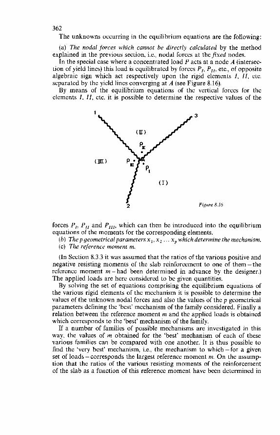
362 The unknowns occurring in the equilibrium equations are the following: (a) The nodal forces which cannot be directly calculated by the method
explained in the previous section, i.e., nodal forces at theJixed nodes. In the special case where a concentrated load P acts at a node A (intersec-
tion of yield lines) this load is equilibrated by forces P,, PI,, etc., of opposite algebraic sign which act respectively upon the rigid elements I, II, etc. separated by the yield lines converging at A (see Figure 8.16). By means of the equilibrium equations of the vertical forces for the
elements I, II, etc. it is possible to determine the respective values of the
1
2
3
Figure 8.16
forces PI, PI, and PI,,, which can then be introduced into the equilibrium equations of the moments for the corresponding elements.
(b) Thep geometrical parameters xl, x2 . . . xp which determine the mechanism. (c) The reference moment m. (In Section 8.3.3 it was assumed that the ratios of the various positive and
negative resisting moments of the slab reinforcement to one of them-the reference moment m - had been determined in advance by the designer.) The applied loads are here considered to be given quantities. By solving the set of equations comprising the equilibrium equations of
the various rigid elements of the mechanism it is possible to determine the values of the unknown nodal forces and also the values of the p geometrical parameters defining the ‘best’ mechanism of the family considered. Finally a relation between the reference moment m and the applied loads is obtained which corresponds to the ‘best’ mechanism of the family. If a number of families of possible mechanisms are investigated in this
way, the values of m obtained for the ‘best’ mechanism of each of these various families can be compared with one another. It is thus possible to find the ‘very best’ mechanism, i.e., the mechanism to which-for a given set of loads-corresponds the largest reference moment m. O n the assump- tion that the ratios of the various resisting moments of the reinforcement of the slab as a function of this reference moment have been determined in
363 advance, these various resisting moments can be calculated. The requisite cross-sectional areas of reinforcement can then be found. It should be noted that the solution obtained by means of the equilibrium
method (i.e., based on the conditions of equilibrium of the rigid elements of the slab) is an upper bound solution and that only if a statically permis- sible bending moment field which at no point conflicts with the plasticity criterion, and which results in the same limit load, is established will it be possible to affirm - thanks to the theorem of uniqueness - that the ‘exact’ solution has been obtained.
Note: The set of equilibrium equations can be directly solved by the usual methods. Alternatively, a procedure of successive approximations may be adopted, which consists in predetermining all the parameters xl, x2 . . . xp. In this way, for each element of the mechanism, a relation between the reference moment m and the applied loads is found. Comparison of the values m,, m2 . . . m, thus obtained for the various elements of the mechanism will provide an indication of the degree of approximation achieved and will also indicate the direction in which the yield lines should be shifted-i.e., the direction in which the parameters xl, x2 . . . xp should be varied in order to obtain a better approximation. The calculation can then be repeated with a fresh set of values xl, x2 . . . xp, and so on, until the approximation obtained is considered to be good enough.
8.3.5 OTHER PROBLEMS
The object of the foregoing treatment of the subject was to summarise the essential aspects of the principles and the procedure of applying the yield line theory to the analysis of slabs in the limit state of flexural failure. With regard to all the points which it has not been possible to deal with
in the limited scope of this exposition it will be necessary to refer to the bibliography, and especially to the references stated in the present chapter. Such points are more particularly:
The method of afJine transformation whereby, subject to the fulfilment of certain conditions, it is possible to avoid having to carry out a direct analysis for an orthotropic slab and, instead, to replace the latter by an equivalent isotropic slab.
Cf. in particular: ref. 4 (pp. 67 to 74) and Ref. 12 (pp. 117 to 126). The extension of the method of superposition of the elastic theory to limit
Cf. in particular: ref. 4 (pp. 74 to 81), ref. 12 (pp. 41 to 45) and ref. 16
The special mechanisms in the vicinity of corners and of concentrated loads,
Cf. in particular: ref. 4 (pp. 82 to 136), ref. 12 (pp. 28 to 36 and 52 to 57). The interaction of a slab and its edge beams in a case where the slab is asso-
Cf. in particular: ref. 4 (pp. 136 to 142), ref. 12, ref. 16 (pp. 264 to 269)
analysis in a case where several load systems are acting simultaneously.
(pp. 261 to 264).
and the general case of curved yield lines (fanwise mechanisms).
ciated with such beams.
and ref. 28.
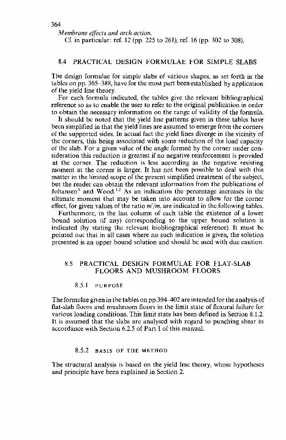
364 Membrane effects and arch action. Cf. in particular: ref. 12 (pp. 225 to 261), ref. 16 (pp. 302 to 308).
8.4 PRACTICAL DESIGN FORMULAE FOR SIMPLE SLABS
The design formulae for simple slabs of various shapes, as set forth in the tables on pp. 365-388, have for the most part beenestablished by application of the yield line theory. For each formula indicated, the tables give the relevant bibliographical
reference so as to enable the user to refer to the original publication in order to obtain the necessary information on the range of validity of the formula.
It should be noted that the yield line patterns given in these tables have been simplified in that the yield lines are assumed to emerge from the corners of the supported side$. In actual fact the yield lines diverge in the vicinity of the corners, this being associated with some reduction of the load capacity of the slab. For a given value of the angle formed by the corner under con- sideration this reduction is greatest if no negative reinforcement is provided at the corner. The reduction is less according as the negative resisting moment at the corner is larger. It has not been possible to deal with this matter in the limited scope of the present simplified treatment of the subject, but the reader can obtain the relevant information from the publications of Johansen3 and Wood.I2 As an indication the percentage increases in the ultimate moment that may be taken into account to allow for the corner effect, for given values of the ratio m'/m, are indicated in the following tables. Furthermore, in the last column of each table the existence of a lower
bound solution (if any) corresponding to the upper bound solution is indicated (by stating the relevant biobliographical reference). It must be pointed out that in all cases where no such indication is given, the solution presented is an upper bound solution and should be used with due caution.
8.5 PRACTICAL DESIGN FORMULAE FOR FLAT-SLAB FLOORS AND M U S H R O O M FLOORS
8.5.1 PURPOSE
The formulae given in the tables on pp.394-402 are intended for the analysis of flat-slab floors and mushroom floors in the limit state of flexural failure for various loading conditions. This limit state has been defined in Section 8.1.2. It is assumed that the slabs are analysed with regard to punching shear in accordance with Section 6.2.5 of Part I of this manual.
8.5.2 BASIS OF THE METHOD
The structural analysis is based on the yield line theory, whose hypotheses and principle have been explained in Section 2.
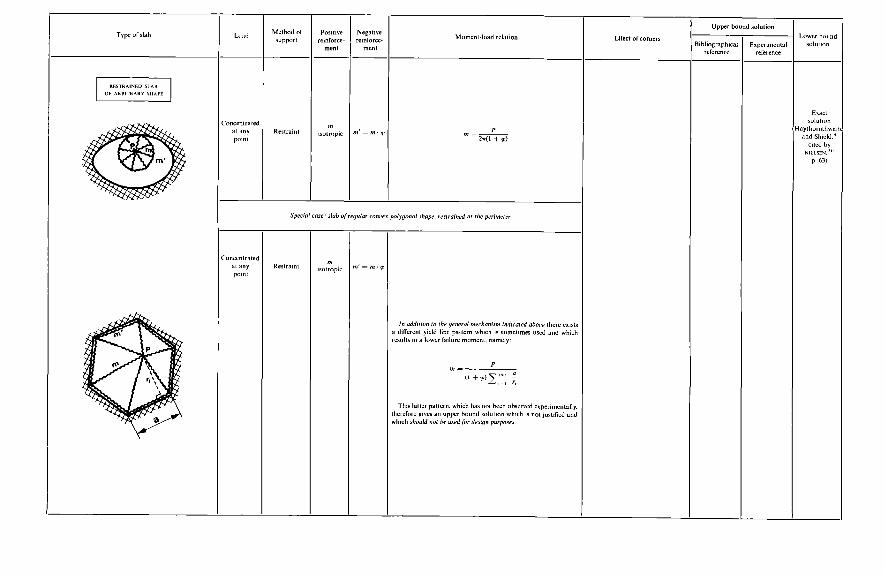
- II € k
a -s ll
a
a ll
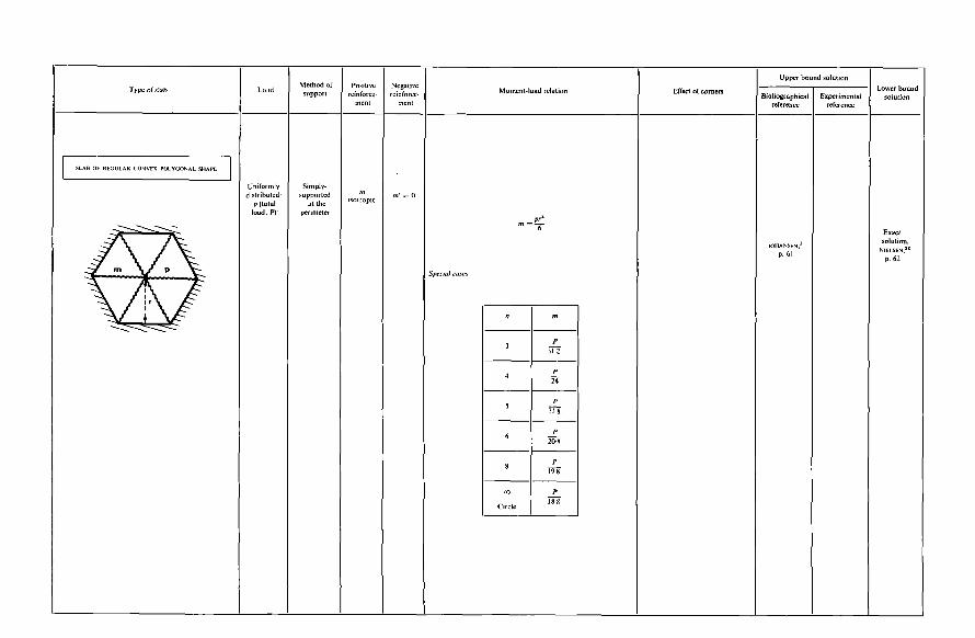
"&I- €
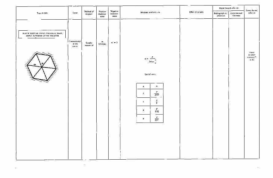
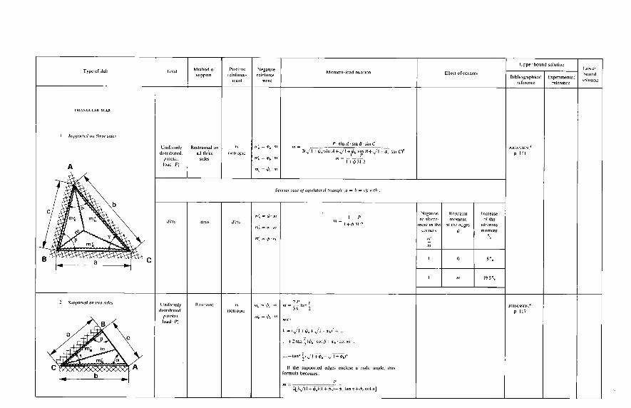
E iE
B
..
.
d'a6
I1 II
Il E
EE
.1
.L
.~
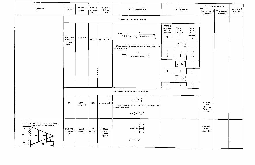
f II II .~
m
m
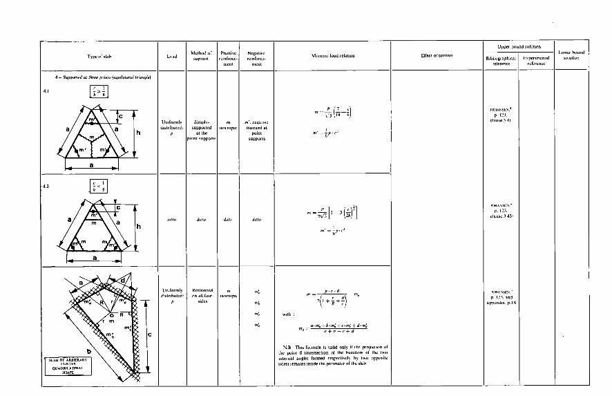
h
Y I< I
c
@
m
P
P
P c
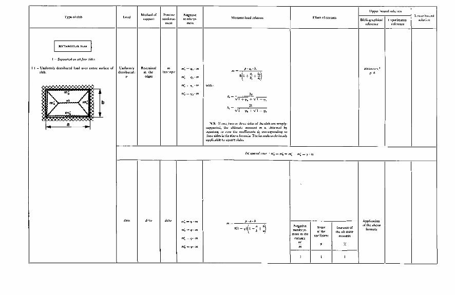
4
c
3
FE
BE
!! !l.
."
II ...
II e
se
a
E€
€€
P
P
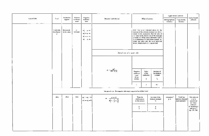
- 0-
o de
$2
e "+
:: II E
O0
Il
II
II II
E Y
P
P
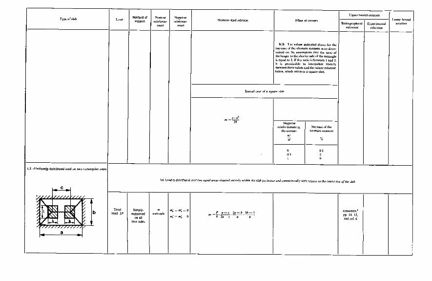
Y j e
-
B 4
O0
II
II
II II
T Y c i'
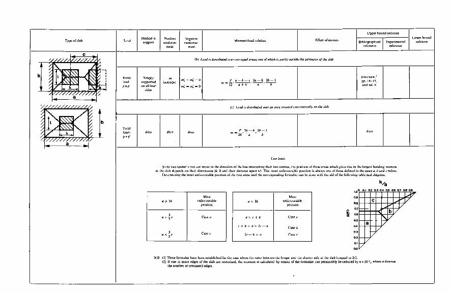
P
P
P
n "
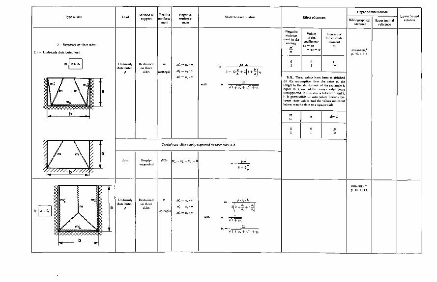
w 19
al II E
c b
t- o
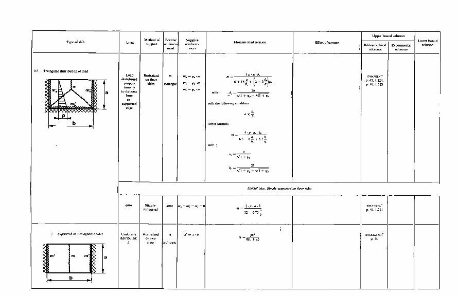
9
Ef
E
Srt&
Il II
II E E E
N
N
v Il Il ."
.- Il
D
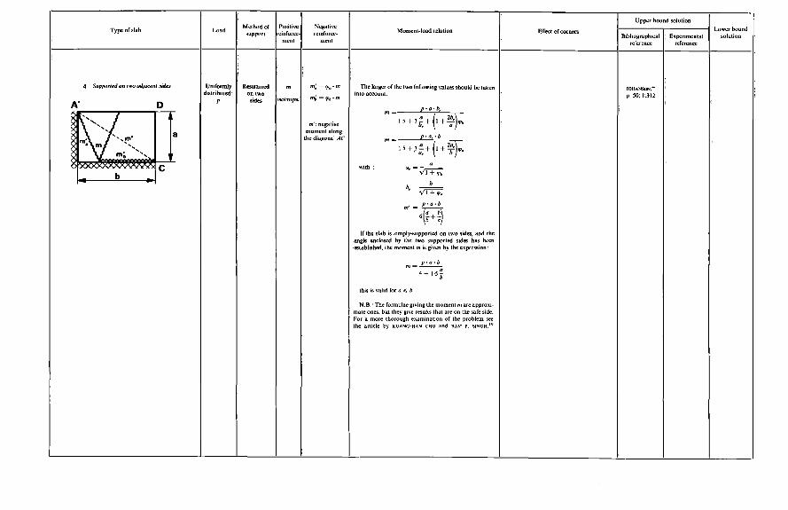
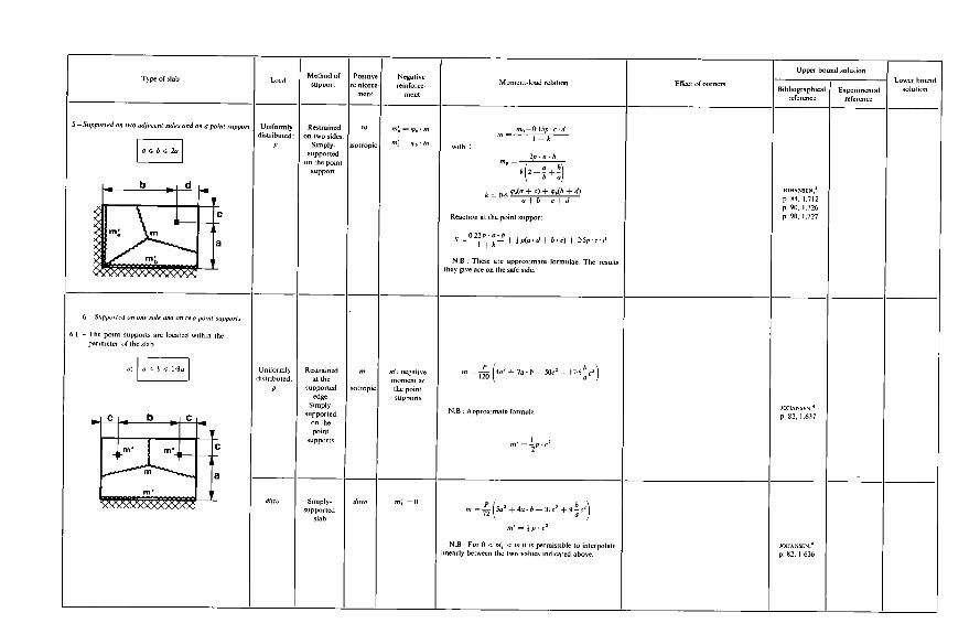
c s P
EC
D
P
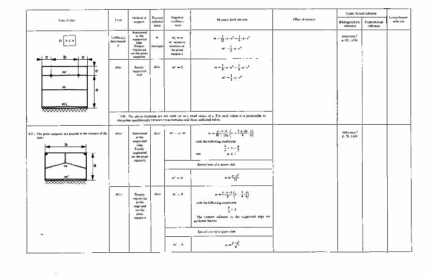
o II E .+
P
A
E B I 'E P
o Il E
P
1
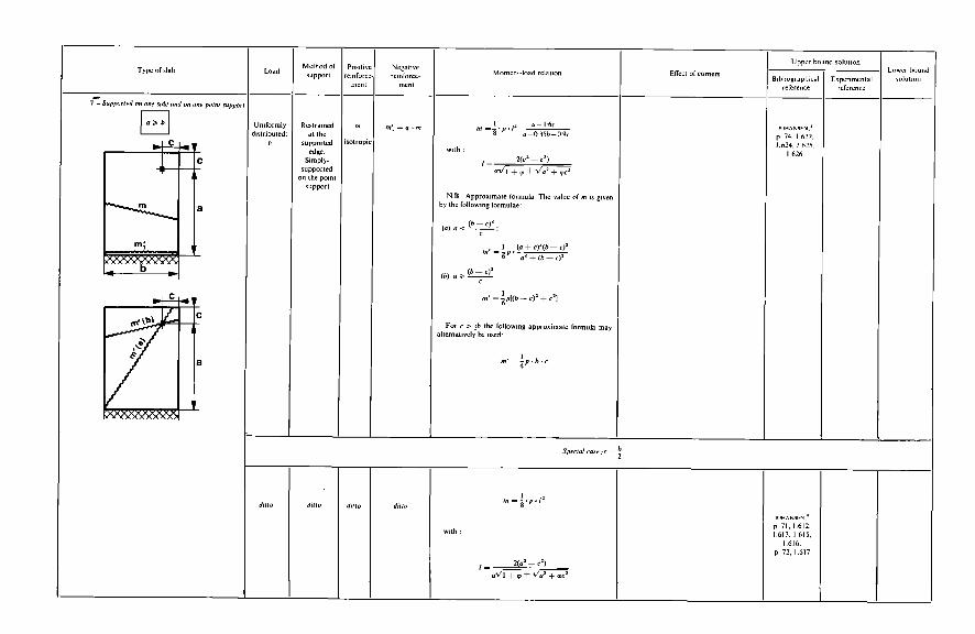
4
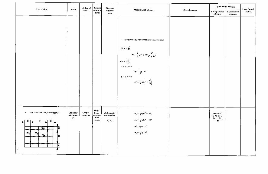
I-
4
-IN
II i
w + ?
Il i
v
-,w
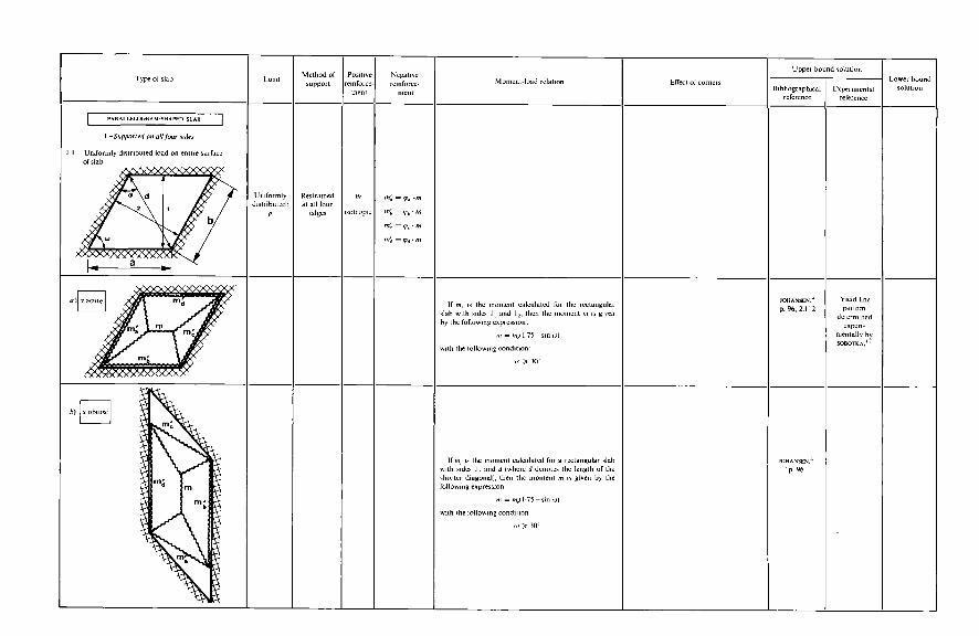
- P
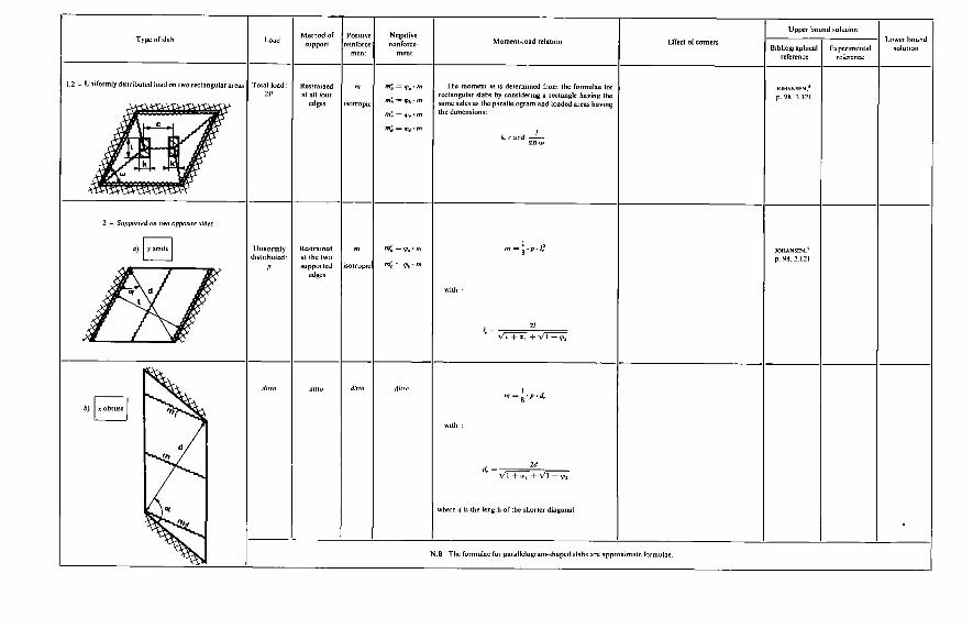
L E
_L
c 3
E!
c
å
II II
E€
.. ."
-3
-3
D
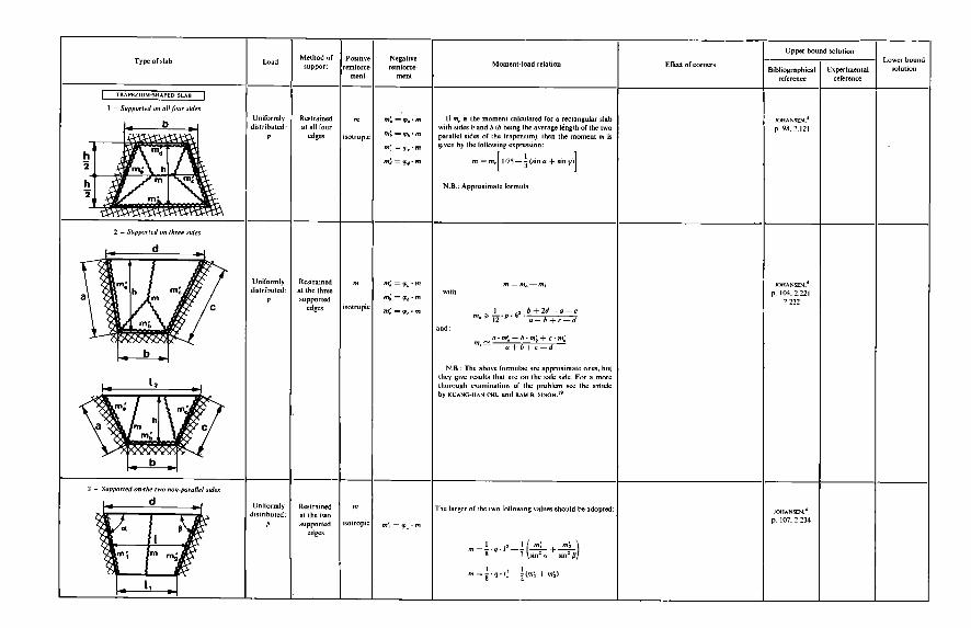
u
4
E.!! S
S%
Z
II II
Il II
E a E i'
€ k Il E .-
E?
o
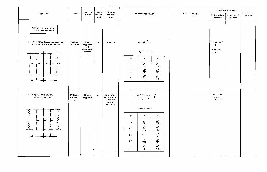
E II h €4
E
h
a v
*- LI“ m
E
E
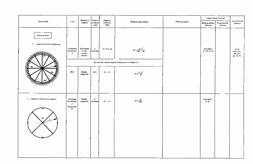
ll
o II s
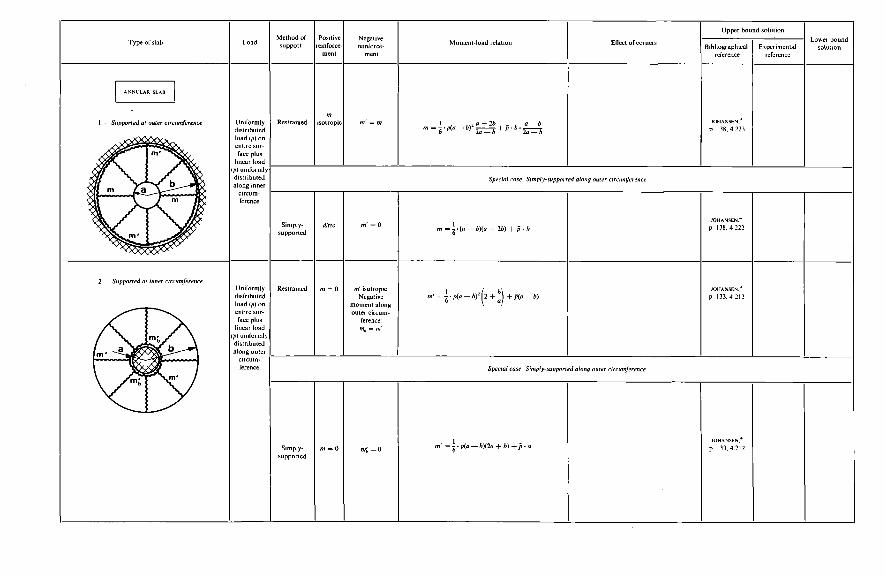
1 i
E II 'c
O II E
O ll E
'9
+ a +
g I .s ? Il a - 10 o
II .~
O Il h
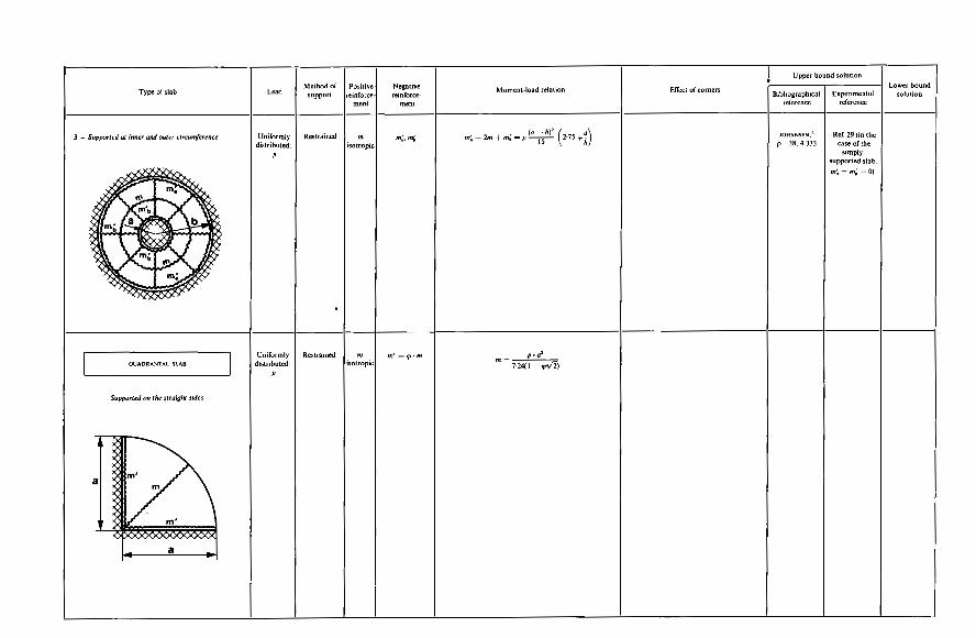
.a
.i
E e. II .€ €g P
II I
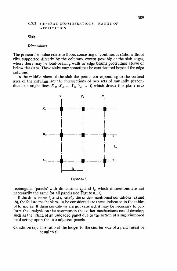
389 8.5.3 GENERAL CONSIDERATIONS-RANGE OF
APPLICATION
Slab
Dimensions
The present formulae relate to floors consisting of continuous slabs, without ribs, supported directly by the columns, except possibly at the slab edges, where there may be load-bearing walls or edge beams protruding above or below the slabs. These slabs may sometimes be cantilevered beyond the edge columns. In the middle plane of the slab the points corresponding to the vertical
axes of the columns are the intersections of two sets of mutually perpen- dicular straight lines XI, X, .... YI, Y, ... yi which divide this plane into
Figure 8.17
.rectangular ‘panels’ with dimensions 1, and l,, which dimensions are not necessarily the same for all panels (see Figure 8.17).
If the dimensions I, and i, satisfy the under-mentioned conditions (a) and (b), the failure mechanisms to be considered are those indicated in the tables of formulae. If these conditions are not satisfied, it may be necessary to per- form the analysis on the assumption that other mechanisms could develop, such as the lifting of an unloaded panel due to the action of a superimposed load acting upon the two adjacent panels.
Condition (a): The ratio of the longer to the shorter side of a panel must be equal to 3.
390 Condition (b): In the direction X (or Y) the ratio of the larger to the smaller
of two spans must not exceed 3.
Reinforcement
The reinforcement is assumed to consist of a grillage of mutually perpen- dicular bars disposed parallel to the directions X and Y.
Column-To-Slab Connection Zone
Definitions
The columns may or may not be provided with flared heads of truncated conical or pyramidal shape. If such columns heads are provided, the term ‘mushroom floor’ is employed; otherwise ‘flat-slab floor’.* If the floor slab does not cantilever beyond the edge columns, the flared heads which may be provided on these columns and on the corner columns are considered to be present only on the inner side or sides of such columns, i.e., away from the slab edges. Furthermore, in some cases the slab may be thickened locally over the
columns. This thickening (on the underside) may be of parallelepipedal or truncated conical or pyramidal shape and is called a ‘drop’.
Mushroom Floors
If the column heads and drops have dimensions conforming to the conditions stated below, it is possible to predetermine the point through which the negative yield lines will pass (cf. Note I). In other cases it will be necessary to determine that point by calculation. Dimensions of the column heads (a) Truncated pyramidal column head In the direction X (or Y) the side length of the top face of the column head should be between i and a of the smaller of the two adjacent spans. (b) Truncated conical column head The sides of a square having an area equal to that of the circular top face of the column head should satisfy the condition a above. Dimensions of the drops (a) Truncated pyramidal drop The height (depth) h, of.the drop should be less than the normal thickness of the slab (see Figure 8.18).
*The term ‘flat slab’ is frequently used to describe both types of floor envisaged here as belonging to one general form of construction. However, in the present treatment it is convenient to retain the distinction,
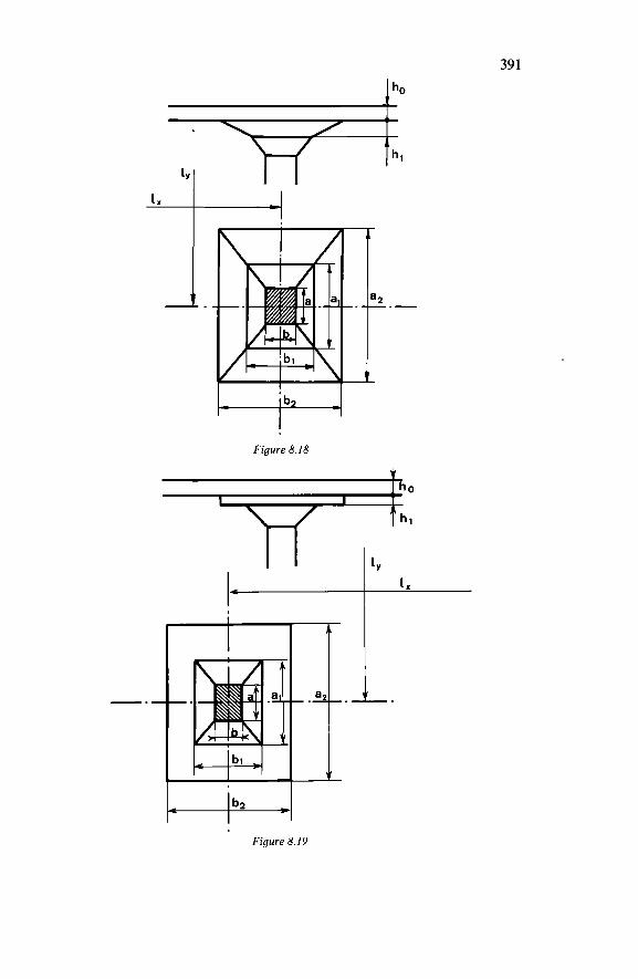
39 I
t
Figure 8.19
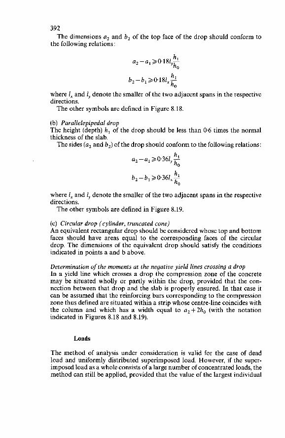
392
the following relations : The dimensions a, and b, of the top face of the drop should conform to
h b,-b1>O.l8l,-' h0
where 1, and 1, denote the smaller of the two adjacent spans in the respective directions. The other symbols are defined in Figure 8.18.
(b) Parallelepipedal drop The height (depth) h, of the drop should be less than 0.6 times the normal thickness of the slab. The sides (a, and b,) of the drop should conform to the following relations:
h a,-a, 20.361 2
y h0
h, h0
b, - b,> 0.361, -
where 1, and 1, denote the smaller of the two adjacent spans in the respective directions. The other symbols are defined in Figure 8.19.
(c) Circular drop (cylinder, truncated cone) An equivalent rectangular drop should be considered whose top and bottom faces should have areas equal to the corresponding faces of the circular drop. The dimensions of the equivalent drop should satisfy the conditions indicated in points a and b above.
Determination of the moments at the negative yield lines crossing a drop In a yield line which crosses a drop the compression zone of the concrete may be situated wholly or partly within the drop, provided that the con- nection between that drop and the slab is properly ensured. In that case it can be assumed that the reinforcing bars corresponding to the compression zone thus defined are situated within a strip whose centre-line coincides with the column and which has a width equal to a,+2ho (with the notation indicated in Figures 8.18 and 8.19).
Loads
The method of analysis under consideration is valid for the case of dead load and uniformly distributed superimposed load. However, if the super- imposed load as a whole consists of a large number of concentrated loads, the method can still be applied, provided that the value of the largest individual
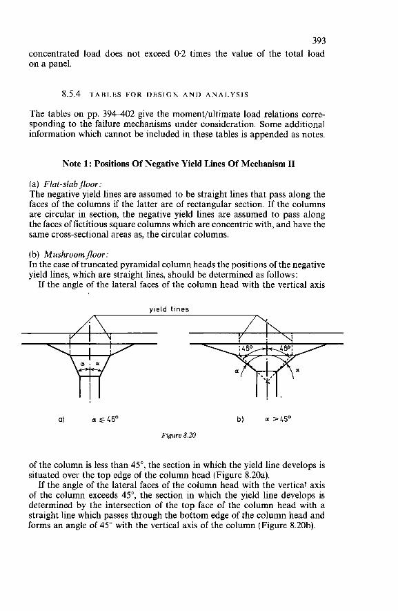
393 concentrated load does not exceed 0.2 times the value of the total load on a panel.
8.5.4 TABLES FOR DESIGN A N D ANALYSIS
The tables on pp. 394-402 give the moment/ultimate load relations corre- sponding to the failure mechanisms under consideration. Some additional information which cannot be included in these tables is appended as notes.
Note 1 : Positions Of Negative Yield Lines Of Mechanism II
(a) Flat-slab floor: The negative yield lines are assumed to be straight lines that pass along the faces of the columns if the latter are of rectangular section. If the columns are circular in section, the negative yield lines are assumed to pass along the faces of fictitious square columns which are concentric with, and have the same cross-sectional areas as, the circular columns.
(b) Mushroomfloor: In the case of truncated pyramidal column heads the positions of the negative yield lines, which are straight lines, should be determined as follows :
If the angle of the lateral faces of the column head with the vertical axis
yield lines
ai C1SL50 b) a >LSo
Figure 8.20
of the column is less than 45", the section in which the yield line develops is situated over the top edge of the column head (Figure 8.20a).
If the angle of the lateral faces of the column head with the vertical axis of the column exceeds 45", the section in which the yield line develops is determined by the intersection of the top face of the column head with a straight line which passes through the bottom edge of the column head and forms an angle of 45" with the vertical axis of the column (Figure 8.20b).
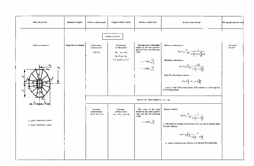
h
o I-
-!+ %If E-
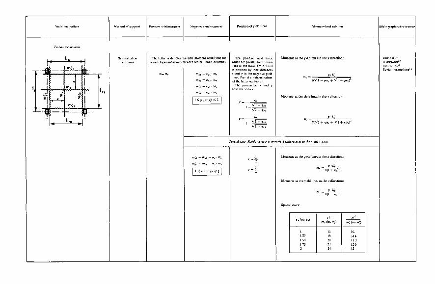
E"
- E
I f
I
z
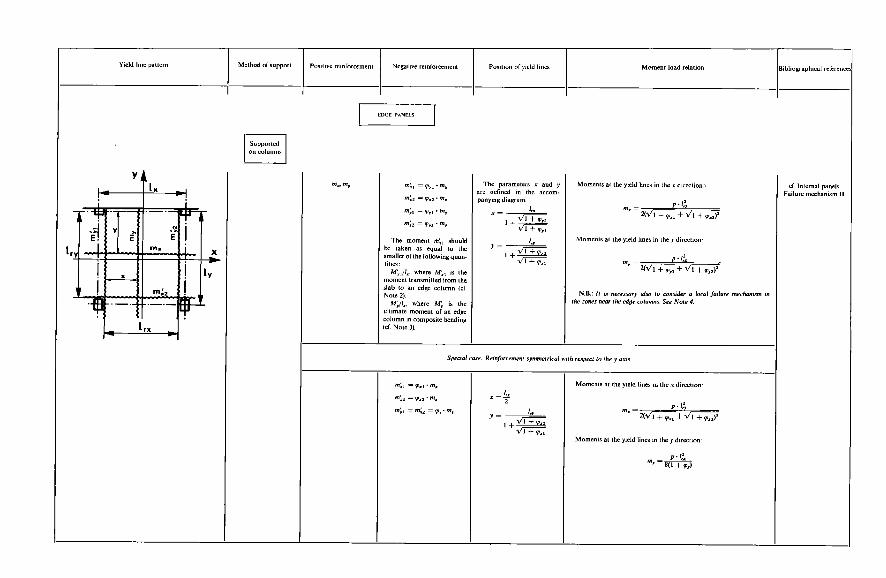
d
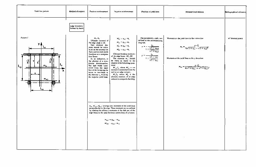
-
.
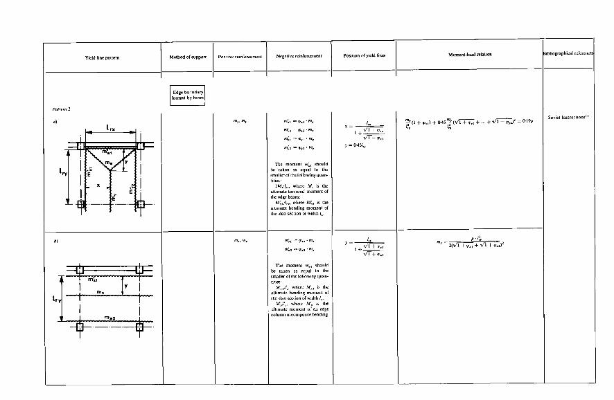
II II
*'
-i
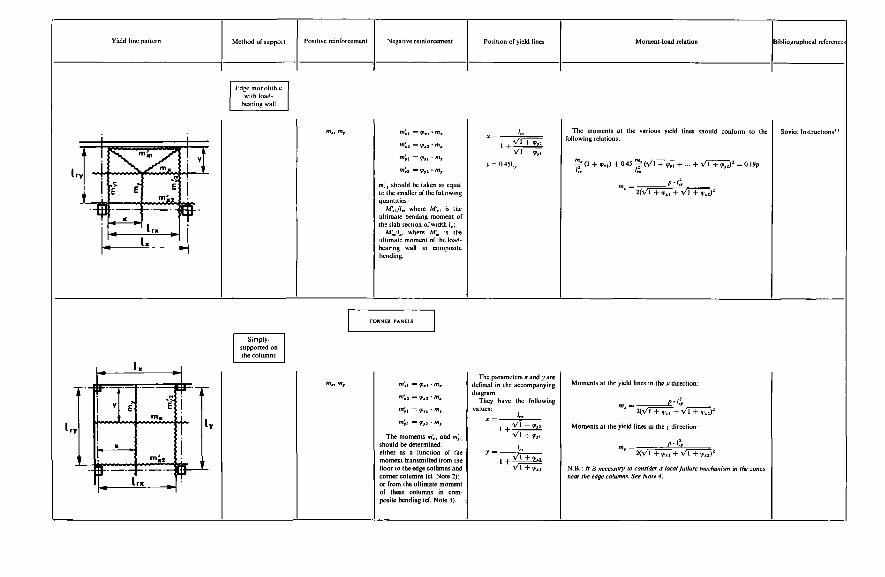
i E
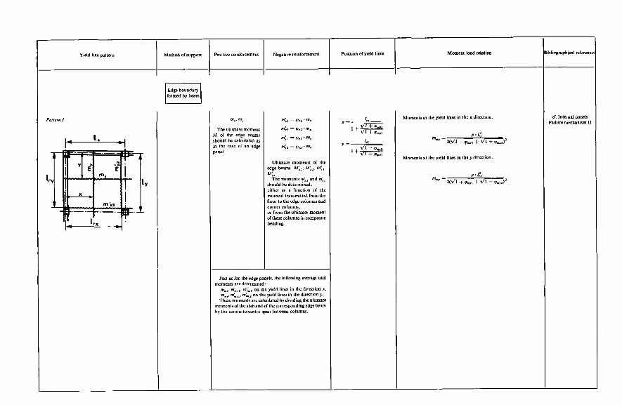
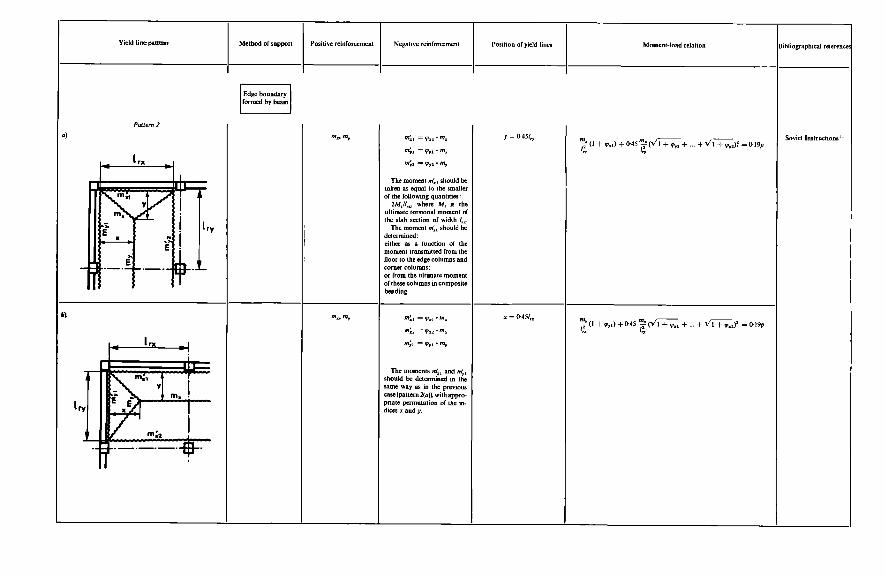
P
o :
II
Ê
4
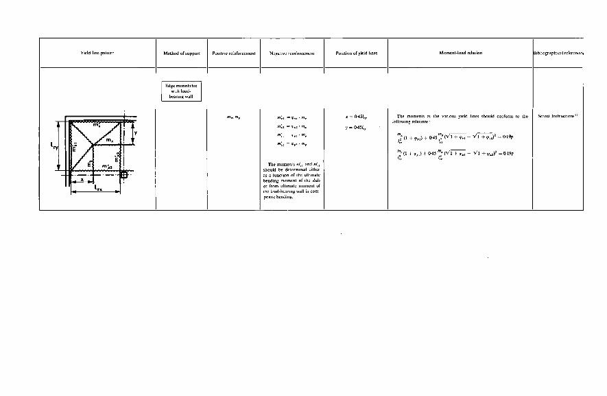
403 In the case of a truncated conical column head, a fictitious truncated
pyramidal column head should be considered whose top and bottom square bases should have areas equal to the areas of the corresponding circular bases of the actual column head. The negative yield line positions should then be determined in the manner indicated for a truncated pyramidal column head.
Note 2 : Slab-To-Column Connection
If the floor is loaded asymmetrically in relation to a row of columns, the slab will transmit some bending moment to each of the columns. It is assumed that to each column is transmitted the moment from a section
of slab whose centre-line coincides with the centre of the column and whose width a,, is defined as follows (see Figure 8.21):
a, = a+2h where a is the-side length of the column cross-section or of the top face
h is the effective depth of the slab. of the column head;
Note 3: Failure Moment Of An Edge Column (Or Corner Column) In Composite Bending
Edge columns: The load transmitted from the floor slab to a row of edge columns should be taken as equal to the load acting upon that part of the slab which is bounded by the yield line X‘X (see Figure 8.22): Of the load acting upon this slab strip bounded by X’X each column
should be assumed to receive a proportion corresponding to the area bounded by the centre-lines of the two panels adjacent to that column (area shown hatched in Figure 8.22). Corner columns: A corner column is assumed to carry the load acting upon the corresponding quarter panel.
Note 4: Local Failure Mechanism Around An Edge Column Or Corner Column
The local failure mechanism liable to develop around an edge column or a corner column can be assumed to have the shapes shown in Figure 8.23: The angle CI which serves to define the shape of the mechanism of pattern
(a) is calculated from the following expression : tan’a =
404
.-. a,,= a + 2 h
Figure 8.21
I i O O o
Figure 8.22
Figure 8.23
405 The positions of the positive yield lines are defined by the distance from
the node A to the edge(s) of the floor in the case of pattern (a), and by the distance from the positive yield line to the corner of the floor in the case of pattern (b). These distances play no part in establishing the moment-load relations corresponding to those mechanisms. However, as the yield lines may pass through differently reinforced slab zones, it is necessary, in applying
I
Figure 8.24
Centre line of columns or edge of f loor
---- -
--E& y- Centre Line of columns
Figure 8.25
these relations, to take account of the positions adopted for the positive yield lines.
Edge column: The moment-load relations are as follows:
D 4s<l:
D r = m,(4+ 1.144,) 1 + 4,/s/l @,> 1:
406 Corner column :
= m,( 1.57 + 0.436,) P = 2m,
P i + 4 JsII 4, < 1 (pattern u):
1 + 4 JsIl 1 (pattern b):
Note 5: Length Of Reinforcing Bars
(a) Positive reinfoficement : The lengths of the bottom reinforcing bars may be determined as follows: Part of the reinforcement should have a length at least equal to I, (or I,). The rest of the bars may have a length less than i, (or i,); the length of
these bars should then be so determined as to avoid giving rise to the failure mechanism represented in Figure 8.24. This mechanism is associated with the following moment-load relationship
(with the notation as indicated in the diagram): PIr4(L-4) = 2m[I~,(1+61)+~1(62-41)1
(b) Negative reinforcement: The negative reinforcing bars should be of sufficient length to obviate the formation of the failure mechanism represented in Figure 8.25. In this mechanism, mi and ml, are the ultimate moments of the slab
sections in which all or some of the negative reinforcement (support reinforce- ment) ceases to be effective. This mechanism is associated with the following moment-load relationship:
P G = 2[J(1+61)+J(1+62)]2
407 REFERENCES
i. BACH, c. and GRAF, o., ‘Versuche mit allseitig aufliegenden quadratischen und recht- eeckigen Eisenbetonplatton’ (‘Tests with square and rectangular reinforced concrete slabs supported on all sides’), Deutscher Ausschuss fur Eisenbeton, No. 30, Berlin (1915)
2. BACH, c. and GRAF, o., ‘Versuche mit zweiseitig aufliegenden Eisenbetonplatten mit kon- zentrierter Belastung’ (‘Tests with reinforced concrete slabs supported on two sides and subjected to concentrated loading’), Deutscher Ausschuss fur Eisenbeton, No. 44 and 52, Berlin
3. IOHANSEN, K. w., ‘Yield line theory’. English translation of the original Danish publication (1931), Cement and Concrete Association, London (1962)
4. JOHANSEN, K. w., ‘Pladeformler’ (‘Slab formulae’), Copenhagen 5. GEHLER, w. and AMOS, H., ‘Versuche mit kreuzweise bewehrten Platten’ (‘Tests with two-
6. IOHANSEN, K. w., ‘Nogle Pladeformler’ (‘More slab formulae’), Copenhagen 7. LEVI, F., ‘Superfici d’influenza e fenomeni di adattamento nelle lastre piane’ (‘Influence
surfaces and adaptation phenomena in flat slabs’), Giornale del Genio Civile No. 5 (1950) 8. HOGNESTAD, E., ’Yield line theory for the ultimate flexural strength of reinforced concrete
slabs’, J. A C Z (March 1953) 9. HAYTHoRNTHwAtTE, R. M. and SHIELD, R. T., ‘A note -on the deformable region in a rigid-
plastic structure’, J. Mech. Phys. Solids, 6, 127-131 (1958) 10. STEINMANN, G. A., ‘La théorie des lignes de rupture’ (‘The yield line theory’), Bulletin
d’lnjormation, C.E.B., No. 27 (September 1960) i i. ‘Instructions soviétiques concernant le calcul des structures hyperstatiques en béton armé‘
(‘Soviet instructions concerning the design of reinforced concrete statically indeterminate structures’) (Chapter IV). French translation, Bulletin d’Information, C.E.B., No. 28 (October 1960)
way reinforced slabs’), Deutscher Ausschuss fur Eisenbeton, No. 70, Berlin (1932)
12. WOOD, R. M., ‘Plastic and elastic design of slabs and plates, London (1961) i 3. NIELSEN, M. P., ‘Plasticitetsteorien for Jernbetonplater’ (‘Plastic theory for reinforced
14. IONES, L. L., Ultimate load analysis of reinforced and prestressed concrete structures, Chatto
15. NIELSEN, M. P., ‘Exact solutions in the plastic plate theory’, Bygningstatiske Meddelelser,
16. MASSONNET, C. and SAVE, M., Calcul plastique des constructions (Plastic design of structures), Vol. II, Brussels (1963)
17. SOBOTKAO, I. z., ‘Etude de la capacité de résistance des dalles biases en béton armë (‘In- vestigation of the strength of reinforced concrete skew slabs’), Bulletin d’Information, C.E.B., No. 38, 84-133 (March 1963)
18. SAWCZUK, A. and JAEGER, T., Grenztragfahigkeitstheorie der Platten (Limit strength theory of slabs), Springer-Verlag, Berlin (1963)
19. University of Illinois: Structurai research series’. Bulletins No. 181, 200, 211, 228, 249, 265, 277; Also: A C Z J O U R N A L Proceedings, 60, No. 9 (September 1963)
20. NIELSEN, M. P., ‘Limit analysis of reinforced concrete slabs’. Acta Polytechnica Scandinavica Ci 26, Copenhagen (1964)
21. MALDAGUE, I. c. ‘Essais de dalles simples ou continues armées de différents types d‘acier’ (‘Tests on single or continuous slabs reinforced with different types of steel’). Bulletin d’Information, C.E.B., No. 44, 47-88 (Oct. 1964)
22. CALLARI, GI E. ‘Méthode générale de calcul des dalles dans le domaine anélastique’ (‘General method for the analysis of slabs in the inelastic range’. Annales de l’Institut Technique, Paris (September 1964) XVIIe Année, No. 201, Série ‘Théories et méthodes de calcul’.
23. ‘Recent developments in yield line theory’. M.C.R. specialpublication (May 1965) 24. KWIECYNSKI, M. w., ‘Yield criterion for initially isotropic reinforced slab’, Magazine of
Concrete Research, 17, No. 51 (June 1965) 25. KWIECYNSKI, M. w. ‘Yield criterion for an orthotropically reinforced slab’, International
Journal of Solids and Structures, 1, No. 4 26. LEVI, F., ‘Contrôle des conditions de fissuration et de déformation des dalles dimensionnées
à l’état limite ultime’ (‘Checking the cracking and deformation conditions of slabs designed for the ultimate limit state’), Bulletin d’Information, C.E.B., No. 50, 201-226 (July 1965)
concrete slabs’), Danmarks Tekniske Hojskolr, Copenhagen (1 962)
and Windus, London (1962)
34, NO. 1, 1-28 (1963)
27. KWIECYNSKI, M. w., ‘Some tests on the yield criterion for a reinforced slab, Magazine of Concrete Research. 17, No. 52 (1965)
28. ROBINSON, I. R. and KARAESMEN, E., ‘Etude expérimentale de dalles bordées de poutres’ (‘Experimental investigation of slabs with edge beams’), Bulletin d’Information, C.E.B., No. 50 (July 1965)
29. GVOZDEV, A. A. and KRYLOV, s. M., ‘Recherches expérimentales sur les dalles et planchers- dalles effectuées en Union Soviétique’ (‘Experimental research on slabs and flat-slab floors carried out in the Soviet Union’), Bulletin d’lnformarion, C.E.B., No. 50, 174200 (July 1965)
30. KUANG-HAN CH, RAM B. SINGH, ‘Yield analysis of balcony floor slabs’, J. ACI Proceedings 63, No. 5. 571-586 (May 1966)
3 i. MASSONNET. CH., ‘Théorie générale des plaques élasto-plastiques’ (‘General theory of elasto-plastic plates’), Bulletin d’lnformalion, C.E.B., No. 56 (August 1966)
32. CORNELIS, A., ‘Etude à l’aide d’une calculatrice électronique du comportement élastique des plaques’ (‘Investigation of the elastic behaviour of plates with the aid of an electronic computer’), Bulletin d’Information, C.E.B.. No. 56 (August 1966)
INDEX
Additional moment, 58, 59 Additives, 148-150 Adhesive tapes, 130 Affine transformation, method of, 363 Aggregates, 137, 139-147 batching, 15 1 cleanliness, 141 crushed stone, 146 grading, 141 granulometric classification, 139 maximum dimension, 141 nature and shape, 144-147 rounded, 146, 152 shape (or volumetric) coefficient, 146 silico-calcareous, 156
Aggressive atmosphere, 301, 302, 304 Air-entraining agents, 148 Amplification coefficient, 25, 53, 182,
Anchorage, bond by, 82 by curvature, 85-89 calculations, 82 dangerous case, 88 devices, 106 of reinforcing bars, 82-91, 104 straight, 83-85 total, 87
presence of, 100
204, 206
Aperture, of infinite length, 101
Bar (notation), 5 Bars, reinforcing. See Reinforcing bars Basic strengths, 210 definition of, 26 determination of, 26-28 of concrete, 27 of steel, 27
Batching, aggregates, 151
Batching, continued
Beams, 91 cement, 150
bar spacings at intersections of, i 10 deep, rules for, 64 design of, 77 diaphragm, 37-38 supports of, 80 thin-walled, 37
composite, 88 Bending, biaxial, 50-51, 54
with compression, rectangular section, 229-234
of reinforcing bars, 104 simple, rectangular section, 224-229
transverse, 38 ultimate limit state for, 238
201- uniaxial. See Uniaxial bending Bending machines, 135 Bending moment diagram, 31, 89 Bending moments, 36, 48, 116, 352 additional, 55 permissible, problem on, 253, 254 redistribution of, 29
Bent-up bars, 122 Binders, vertical or inclined, 120 Binding, geometrical dimensions of zone
provided with, 1 1 5 helical, 115 members reinforced by, 52, 11.5-1 16 members without, 51 minimum percentage of, 115 reinforcement, 115 in mats, 116
Binding coefficient, 53 Bond, 82-92 by anchorage, 82 by interaction, 82, 91-92 definition of, 82
409
410 Bond length, 85, 290 deformation along, 291
Bond stress, 83-84, 91, 300 anchorage, 302, 304 distribution between concrete and steel, 287
Braced columns, 57 Buckling, 35, 36, 38, 54, 55, 117, 131 Buckling moment, 58
Calcium chloride, 148-150 Calculations. See Design calculations Cantilevers, vertical, 37 Capping, 165 Castellations, 122 Cement, 137-139 air-entraining, 148 batching, 150 choice of, 138 classification and quality of, 137 Portland, 137, 138 rapid-hardening, 138 storage of, 139
determination of, 24 effect of, 28
concrete, 208 steel, 208
definition, 201-204 permanent loads, 204 superimposed loads, 205-207
Characteristic loadings, 200, 201, 210
Characteristic strengths, 200, 201, 207-210
Characteristic values, 201-207
Chlorides, 149 Circular drop, 392 Climatic superimposed loads, 26, 182 Cold weather, concreting in, 172 Column-to-slab connection zone, 390 Columns, 111-115 braced, 57 corner, 403, 407 edge, 403, 405 longitudinal reinforcement, 112 minimum section, 1 1 1 piacing reinforcement in position, 114 transverse reinforcement, i 13
Comité Européen du Béton, 24, 199, 200,
Compatibility equation, 229, 232, 233 Compression, concentric, 51-54, 57, 224, 236
206, 209, 210, 287, 305
concrete in, 40, 211-212 eccentric, 58, 59, 72, b:, 222, 234 notation, 5
Compressive flange, effective width of, 40 Compressive strain of concrete, 43, 44, 212
Compressive strength of concrete, 19, 27, of steel, 212
164-166
Compressive zone, 78-79, 94, 21 1 and torsional strength, 95 width of, 40
Concentric compression, 51-54, 57, 224, 236 Concrete, 19-23, 210 basic strength, 27 characteristic strength, 208 composition, 137-159 compressive strain, 43, 44, 212 compressive strength, 19, 27, 164166 consistency, 169 control tests, 160, 162 creep. See Creep crushing. See Crushing; Crushing test curing. See Curing definition, 137 deformations of, long-term linear, 23 design strength, 208 elasticity modulus, 22-23 freshly mixed, 137 handling, 168 high-density, 152 in compression, 40, 211-212 information tests, 160, 162 making, 167-168 putting materials into mixer, 167-168
mechanical strength, 19 minimum strength of, problems on, 247,
mixing procedure, 168 normal, 152 placing, 168 plastic, 152 Poisson’s ratio, 23 prestressed, 138 properties of, 237 reference values of mechanical strength, 19 requirements, 137-174 sampling, 160 shrinkage. See Shrinkage strength of, 207 stress distribution diagram, 21 1 stress-strain diagram, 46, 313 tensile strength, 2CL22, 28, 166167, 288,
testing strength of, 159-167
252, 256
302
age at testing, 164 compressive strength, 164-166 procedure, 164167 specimens, 162 tensile strength, 166167
thermal expansion coefficient, 23 Concrete cover to reinforcing bars. See
Concrete mix, consistency of, 154-159 Concrete mix design, 152 Concrete strain, determination of, 312 Concreting, checks prior to, 168
under Reinforcing bars
in cold weather, 172
Concreting, continued in warm weather, 173-174 interruption and resumption of, 170
Conditions of execution, 126 Connection zone, column-to-slab, 390 Connectors, 73-76, 81 definition of, 73 fastening, 83, 106, 107
transverse, 83 design of, 88-89
Conseil International du Bâtiment, 24, 199,
Construction joints, 17C171 Construction procedure, effect of, 26 Constructional arrangements, 102-123
Control tests on concrete, 160, 162 Correction factors, 20 Crack spacing, maximum, 292, 294, 295,298 Crack width, calculation of, 290 maximum, 292, 294, 296, 298
permissible, 301 reference definition of, 286
200, 209, 210
and design assumptions, 102
expressions for, 299
Cracked members, deflection, 315 Cracking, 30, 53-54, 60, 73, 83, 94, 120, 330 accidental, 290 analysis of, 285-310 purpose of, 286
calculation of, 286 in flexural member, 295-299 in normally reinforced members, 291-
in T-beam reinforced with medium-
in T-beam reinforced with plain mild
in tie-member reinforced with medium-
in tie-member reinforced with plain
in under-reinforced members, 288-291 purpose of, 292 worked examples, 293, 297
299
tensile deformed bars, 298
steel bars, 297
tensile deformed bars, 294
mild steel bars, 293
checking of, 62, 300-310 classification of structures according to
flexural, 295-299 in concrete, 285 in reinforced concrete, 286-300 limit state of. See Limit state of cracking longitudinal, 286 non-systematic, 302 practical checking of, 60 progressive development of, 288 systematic, 292, 304 tensile, 285 calculation of, 292
web, 64
consequences of, 61-62
41 1 Cracking shear, 286 Creep, 26, 58, 59, 313, 324-328 effect of, 60 influence of age of concrete at time of
influence of composition of concrete, 325 influence of least dimension of member,
influence of time, 327
basic, 324
loading, 326
325
Creep coefficient, 324
Cross-members with haunches, 57 Cross-section of member, problem on, 250 Crushing of concrete, 103, 105 Crushing test, 19, 161, 162, 164-166 Curing, 171-172 membrane, 172 steam, 171 wet, 172
Dance halls, i84 Deflection curves, 71 general calculation of, 31 5-316
Deflections, cracked members, 7 1, 3 15 general calculation of, 3 15-3 16 general rules for calculation of, 71 maximum permissible, 70 simplified calculation for ordinary build-
uncracked members, 72, 316
along bond length, 291 flexural, calculations of, 31 1-319 limit state of. See Limit state of de-
of concrete, long-term linear, 23 simplified calculation for ordinary build-
Design calculations, arithmetical accuracy,
ings, 316-319
Deformation(s), 69
formation
ings, 316-319
124 basic data for, 124 object of, 1-2 submission of, 124
Design formulae, 364 for flat-slab floors and mushroom floors,
range of application, 389 364
Design graphs, 310 Design loadings, 201 Design method, general procedure, 2
Design strengths, 200, 207-209 semi-probability, 24, 199-201, 209, 210
concrete, 208 steel, 208
Design values, 201-207 permanent loads, 204 superimposed loads, 205-207
412 Designs, fundamental assumptions, 21 1 preparation of, 12&127
Diaphragm beams, 37-38 Direct force, 54 Dispersion coefficient, 202, 206, 207 Displaced diagram, 90, 116 Disturbed zones, concept of, 342 Draw effect, 293 Drawings, formwork, 126 preliminary design, 125 reinforcement, 126 working, 125-126
Dwellings, 183 Dynamic coefficient, 25. 182 Dynamic pressure, 189-190 formula, 190 nominal and exceptional, 190 values, 190
Earthquake. 26, 107, 182, 206 Eccentric compression, 58, 59, 72, 88, 222,
Eccentricity, 35-36, 54, 58, 59, 235 maximum, problems on, 270, 276
Effective length, 55 Effective width of compressive flange, 40 Elastic behaviour, 330 Elastic limit, fictitious, 310
234
of reinforcing bars, 107. 112 of steel, 17
Elastic theory, 34, 35 Elasticity modulus of concrete, 22-23 Elasto-plastic design with limited rotations,
Elasto-plastic theory, 332 Elongated shape, outline of, 100 Embedment section, 62 Equilibrium, method of, 350-363 Equilibrium of forces, equation of, 222 Equilibrium of moments, equation of, 223 Equilibrium equations, 215, 228, 229, 232,
Euler criticai stress, 36, 58 Euler slenderness ratio, 55 Expansion. See Thermal expansion External tensile forces, 285, 289
31
233, 236, 350, 361-363
Failure, 335 determination of moment of, 215, 218 determination of type of, 214 due to tensile cracking, 285 envisaged mode of, definition of, 329-330 flexural, 33C~345 behaviour of plane reinforced concrete
structures up to, 330-331 prediction of nature of, 213 types of, 213
Fictitious thickness, 321, 325 Flanges and ribs, junctions between, 81 Flexural members, 116123 changes in geometrical shapes of sections,
118 Flexural test, 21, 161, 167 Floors, 36 flat-slab, 56, 393 design formulae, 364
mushroom, 56, 393 design formulae. 364
ribbed, 40, 56, 78. 79, 318
checking, 169 classification, 128 cleaning, 131 fine-faced, 129 joints in, 130 maintenance, 132 mechanical properties, 130 oiling, 131 ordinary, 128 preparation, 131 requirements, 128-133 sag and camber, 131 special, 129 striking, 132 tightness, 130 wetting, 131
Formwork drawings, 126 Frost, 172-173 Full fixity, 56
Formwork, carefully finished, 128
Garages, 184 Geometrical length, 56 G/S coefficient method, 152
Haunches, 118
Helical binding, 115 Hooke’s law, 18, 49. 212 Hooks, 105, 106
Hoops, 115 Hospitals, 183
cross-members with, 57
standard, 86, 87
Indices, 5 Information tests on concrete, 160, 162 Instability, limit state of. See Limit state of
Interaction, bond by, 82 instability
Kinematic theorem, 334, 344 Kinking effect, 343-344
Lapping. splicing of bars, by 90, 105 Laps in compressive reinforcement, 106 in tensile reinforcement, 105 Lattice hypothesis, 76, 92, 94
Length, geometrical, 57 Limit analysis, general theory of, 333 application, 336345
Limit state, 2, 28, 54 envisaged, definition of, 329 ultimate, 39, 204, 208. 209, 213, 33G345 analysis methods, 331-345 for simple bending, 238
286 Limit state of cracking, 60-69, 205, 208, 209,
definition, 60 fundamental design assumptions, 60
Limit state of deformation, 69-73, 205, 208, 209
definition of, 69 fundamental design assumptions, 69 simplified rules for ordinary buildings, 72
Limit state of instability, 5&60, 205, 208, 209 columns loaded in concentric compression
57 in eccentric compression, 58
fundamental design assumptions, 54 of plates loaded parallel to plane, 59
Linear members, structures composed of,
Load, permanent. See Permanent loads
Load-bearing partitions, 35 Load capacity, 223 Loading tests, 186 Loadings, characteristic. See Characteristic
loadings Lower boundary theorem, 334, 344
29-32
superimposed. See Superimposed loads
Materials, properties of, 237 determination of, 16-23
Mats, binding reinforcement in, 116 Mechanical reference properties of steel, 17 Mechanical strength of concrete, 19 Method of affine transformation, 363 Method of equilibrium, 350-363 Method of nodal forces, 350-363 Method of superposition, extension of, 363 Method of work, 349-350 Minimum effective percentage, 289, 291 Mobile equipment, 186 Modular ratio, 1 Modulus of elasticity. See Elasticity modulus Mohr’s circle, 339, 340, 342 Moment-curvature diagrams, 31 Moment equation, 228, 229 Moment-load relations, 405,407 Moment-ultimate load relations, 393 Moments, redistribution of, 30
413 Mortar, R I L E M standard, 138 Moulds for test specimens, 160-162 Multi-storey buildings, 184
Navier-Bernoulli hypothesis, 39, 21 1 Nodal forces, 343, 346, 351 calculation, 356-361 determination, 35 1-36 1 edge, 361 expressions for, 358-361 method of, 350-363
Non-linear design, 32 Normal criterion, 342 Notation, &15
Offices, 183 Orthotropic reinforcement, 354, 355
Parabolic diagram, 46, 48 Parallelepipedal drop, 392 Parapets, horizontal forces on, 186 Partitions, lightweight demountable, 185 load-bearing, 35
Permanent loads, 25, 202, 203 characteristic values, 204 design values, 204 determination of effects of, 29-38
Plane structures, 69 loaded parallel to middle plane, 34 loaded perpendicularly to middle plane, 32
Plastic behaviour, 331 criterion, 336-337
Plastic design, 31 Plastic hinges, 32 Plastic theories, 34 Plasticisers, 148 Plasticity, instantaneous, 313
Plastification, 330-33 i Poisson’s ratio for concrete, 23 Portland cement, 137, 138 Prime, use of, 5 Probability theories of safety, preliminary
long-term, 313
considerations, 198-199 principles of, 199
Proof stress, 19 Properties of materials, 237 determination of, 1623
Protected ordinary structures, 301, 303. 310 Public entertainment buildings, 184 Punching shear, 97-101, 330 limit value of resistance to, 98
Punching shear reinforcement, 120-123 Punching shear strength, 97 determination of, 98-101
414 Rectangular diagram, 47 Rectangular section, 280-284 analysis of, 2 18-236
229-234 composite bending with compression,
concentric compression, 236 eccentric compression, 23&236 for simple bending, 22&229 procedure for, 228, 233-235
determination of failure moment, 218 general formulae, 272 reinforcement, 219-224 with compressive reinforcement, 226, 258-
without compressive reinforcement, 225.
Redistribution of forces and moments. 30,
Redistribution coefficients, 32 Reduction coefficients, 27-28. 43, 49, 9496,
Reference moment, 349, 352 Reference resisting moment, 346 Region coefficient, 190 Reinforced concrete structures, field of
Reinforcement, 61, 390
26 I
250-258
203-204
192, 200, 201, 207. 208, 210, 313, 314
application of Manual, 1
anisotropic, 336 binding, 52, 115 in mats, 116
compressive, 50, 258 laps in, 106 longitudinal, 117
congestion of, 169 connector, 73-76, 81. 95 corner, 120 cross-sectional area of, problem on, 250,
design rules for, 302-310 255-257, 259. 264, 277, 283
normally reinforced members, 304310 under-reinforced members, 302-304
designing and checking, 219-224 edge, 119 general conditions relating to, 102-1 11 high percentage of, 305 isotropic, 336, 354, 355 longitudinal, 95. i 12 constructional arrangements, iì3 minimum percentage, 112 longitudinal distribution, 117
low percentage, 305 mechanical percentage, 30 mid-span, 119 minimum effective percentage, 289, 291 minimum strength of, problem on, 249 miscellaneous systems, 122 negative, 407 orthogonal, 336 positioning, 137
Reinforcement coniinued positive, 407 punching shear, 120-123 requirements, 133-137 skin, 64, 117 suspension, 8 1 tensile, 49 laps in, 105 problems on. 245. 247, 271
tensile longitudinal, 116 tolerances, 175-176 torsional, 95 transverse, 78, 80, 82, 83, 88, 96, 106, 113,
I17 constructional arrangements, 114 contribution to torsional strength, 94 effect of, 287 minimum percentage, 77, 93. 114
under-reinforced members, 288, 300-304 welded fabric, 90 see also Reinforcing bars
Reinforcement cage, 114 Reinforcement drawings, 126 Reinforcing bars, 62 anchorage of, 82-91, 104 bend tests, 134 bending, 104, 134
135 bending method, 135 bending speed, 136 bent-up, 122 classification, 16 compressive, 91 concrete cover to, 110-1 1 i all bars, 110 'groups of bars in contact, 11 1 main bars, 1 1 1 minimum, 175
curtailment of, 105 definition, 16 deformed, 92 design of, 64 devices used at ends, 105 diameters, 17, 63 different grades or types of, 126 elastic limit, 107, 112 groups of bars in contact, 109-110 interaction bond, 91-92 length of, 407 longitudinal, 95. 1 i2 curtailment of, 89-90
mechanical properties reference values, 133 permissible curvature, 103 positioning, 137 spacers, 137 spacing, 108-1 10
minimum diameter of forming mandrel
at intersections of beams, 110 in same horizontal layer, 109
Reinforcing bars continued in same vertical line, 108
splices in. 104108 lapped, 90, 105 staggered, 106 welded, 107,108
straightening, 136 sudden changes of section, 105 tensile longitudinal, i 16 tests on, 133 transverse, 73, 113 use of different grades or different types,
welding, 107-108, 136-137 Relative failure moment, 224 Relative standard deviation, 202, 207, 208 Relative ultimate moment, 224 Residential buildings, 25, 26 Resisting moment, 48
Ribbed floors. See Floors Ribs, design of, 77
RILEM standard mortar, 138 Ritter-Mörsch theory, 76 Roofs, 186, 193, 195 cladding elements, 196 flat, 183
102
problems on, 244, 270, 276
junctions between flanges and, 81
Rules of good construction, 60-61
Safety, checking for, method of, 209-210 principle of, 24 problems on, 267-270, 275, 282
determination of, 24-28. 198-210 factor of, 198, 201, 210, 238 preliminary considerations, 198 probability theories of, preliminary con-
siderations, 198-199 principles of, 199
structural, problem on, 240 Sampling, concrete, 160 Sand, 144 Sand equivalent (SE) test, 144 Schools, 183 Sea water, 147 Sections. changes in geometrical shapes of,
118 determination of, 39-101 estimation of local strength of, 29 rectangular. See Rectangular section sudden changes of, 105 symmetrical. See Symmetrical section
Semi-probability design method, 24, 199-201,
Setting accelerators, 148 Setting retarders, 148 Shear force, 38, 76-82, 350
209, 210
41 5 Shear force continued design rule for, 76 torsion combined with, 96 total resistance capacity for, 79
Shear heads, 122 Shear resistance capacity, 78-79. 81-82 Shear strength, calculation of, 76 Shells, 89, 91
Shops, 183 Shrinkage, 26, 54, 285, 293, 295, 298. 299,
influence of composition of concrete, 322-
influence of least dimension of member.
influence of time, 324 Shrinkage coefficient, 320 basic, 321
Site coefficient, 191 Skin reinforcement, 64, 117 Slab-to-column connection. 403 Slabs. 69
design of, 82
315, 32&324
324
32 i
analysis of, 334 design, 82 design formulae, 364 punching shear strength, 97
Slenderness ratio, 55, 72, 318 Slump test, 154, 156, 159 Snow, 26, 182 Spalling, 88 Splices. See under Reinforcing bars Splitting test, 19, 21, 161, 162, 166-167 Staggered splice, 106 Standard hook, 86, 87 Static theorem, 335 Statically determinate system, 31 Statistical data, 198, 200 Steel, 16-19, 49, 50, 210 basic strength, 27 characteristic strength, 208 compressive strain, 212 design strength, 208 elastic limit, 17 mechanical reference properties, i7 properties of, 237 strength of, 207 stress-strain diagram, 18-19, 49, 50, 212 tensile strain, 212
Steel strain, 312 Steel stress, 29, 50 Steelfixing tolerances, 175 Stiffeners, 35 Stiffness, 55-56 Stores, 183 Strain. concrete, determination of, 3 i2
Strain compatibility condition, 21 1, 222 Strain compatibility equation, 21 i, 223
steel, determination of, 312
416 Strain hypothesis, 51 Strength, basic. See Basic strength
Stress, steel, 29, 50 Stress distribution diagram for concrete, 21 1 Stress hypothesis, 51 Stress-strain diagram, basic compressive, 21 3
guaranteed minimum, 26
for concrete, 46, 313 for steel, 18-19, 49, 50, 212
Subscripts, 5 Superimposed loads, 181, 202, 203 characteristic values, 205-207 climatic, 26, 182 definitions, 181 design values, 205-207 determination of effect of, 29-38 dynamic, 25, 182 exceptional, 206 fixed, 25, 181 nominal values, 181 superposition of, 206 variable, 25, 181, 182-187 rules relating, 184-187
Superposition, method of, extension of, 363 of superimposed loads, 206
Supports of beams, 80 Suspension reinforcement, 81 Swelling, 64, 291, 310 Symbols, 5 Symmetrical section, arbitrary, analysis of
213-218 analysis of, general procedure of, 217-
with respect to piane of bending, 238-
expression for upper limit of moment, 216 expression for b/h) limit, 214 failure moment, 215 failure type, 214 y/h as function of section properties and
228
250, 267-272, 279-280
external loadings, 213
T-beams, 40, 43, 44, 78, 79, 96, 261, 297, 298 T-section, 261-267 analysis of, 264 problems on, 264, 266 effective width of compressive flange,
261-264 Tangential actions, 73, 83
Temperature variations, 26, 285, 288 Tensile forces, external, 285, 289 Tensile strain of steel, 212 Tensile strength of concrete, 20-22, 28,
Tension, concentric, 53-54
fundamental design assumptions, 73
166-167, 288, 302
notation, 5
Terminal forces, 350
Theatres, 184 Thermal expansion coefficient of concrete, 23 Tie-members, calculation of cracking in, 293,
Tie-rod analogy, 63, 299-300, 304 Tolerances, 174-1 76 dimensional, 174 minimum concrete cover to reinforcement,
more than one, 176 on perpendicularity, 174 on straightness, 175 position of main reinforcement. 176 position of transverse reinforcement, 176 reinforcement, 175-176 steelfixing, 175
Torsion, 92-97 combined with shear force, 96
Torsional moments, 350, 352 Torsional resistance capacity, 94, 96 Torsional strength, and compressive zone, 95 calculation of, 92 transverse reinforcement contribution, 94
Total resistance capacity for shear force, 79 Truncated pyramidal drop, 390
calculation of, 354-356
294
175
U-hook, 86 Ultimate limit state, 39, 204. 208, 209, 213,
330-345 analysis methods, 331-345 for simple bending, 238
Ultimate strength, analysis of, 39 Unbalanced thrust, 88-89, 105, 107 Under-reinforced members, 288, 302-304 UNESCO simplified design method, 210 Unfitness, notion of, 1-2 Uniaxial bending, 39, 43, 51, 54
with tension, 279-284 composition, with compression, 267-279
practical design calculations, 237-284 simple, 238-267 theoretical analysis, 21 1-236
Uniqueness, theorem of, 335 Units, 3 4 basic, 3 relations between S.I. units and metre/
kilogramme-force/second system, 4 secondary, 3 S.I. system, 3
Unprotected ordinary structures, 301, 303,
Unsupported corner, 101 Unsupported edge, 100 Upper boundary, theorem of, 335
305
Vehicle access, 184 Vibration, 162, 164, 168-170 external. 169 internal, 169, 170 surface, 169, 170
Vibrations, 182 Vibrator, 109, 162, 169, 170
Wall element, wind effect on one face of, 189 Walls, 35 Warehouses, 184 Warm weather, concreting in. 173-174 Water, 147-148 permanent contact with, 64 quantity of, 154
Watertight structures, 61, 301, 302, 304 Welding of reinforcement, 107-108, 136 Wetting agents, 148 Wind-bracing, 35, 36, 37 Wind effects, 26, 106-107, 182, 187-197, 206 blocks joined together in single row and
checking procedure, 187 definitions and general principles, 188 dynamic pressure, 189-190 exposure of surfaces, 188 external actions, 193
covered by one roof, 197
417 Wind effects continued internal actions, 193, 196 local actions, 195-196 on one face of wall element, 189 overall actions, 197 projected area, 189 reductions, 191 screening, 191 sphere of application, 187 suction effects, 195 unit values of resultant actions on walls
and roof slopes, 196 Work, method of, 349-350 Workshops, 184
Yield line method, 344 Yield line patterns, 346347, 364 Yield line theory, 34, 345-364 application of, 345 failure mechanism, 346-349 principles of, 345
356. 358 Yield lines, 335, 337, 338, 342, 343, 345, 355,
negative, 393 positive, 405
stepped criterion of (Johansen), 336-345, Yielding, 331. 335, 343
358