Embed Size (px)
Citation preview
REINFORCED CONCRETE 10423522
Dr. Murat Serdar Kırçıl
İNM 1-024
www.yildiz.edu.tr/~kircil
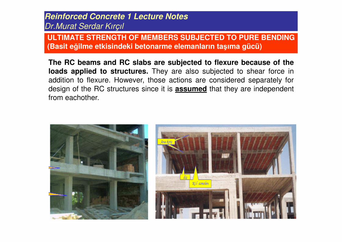
ULTIMATE STRENGTH OF MEMBERS SUBJECTED TO PURE BENDING(Basit eğilme etkisindeki betonarme elemanların taşıma gücü)
The RC beams and RC slabs are subjected to flexure because of theloads applied to structures. They are also subjected to shear force in
addition to flexure. However, those actions are considered separately for
design of the RC structures since it is assumed that they are independent
from eachother.
Reinforced Concrete 1 Lecture Notes
Dr.Murat Serdar Kırçıl
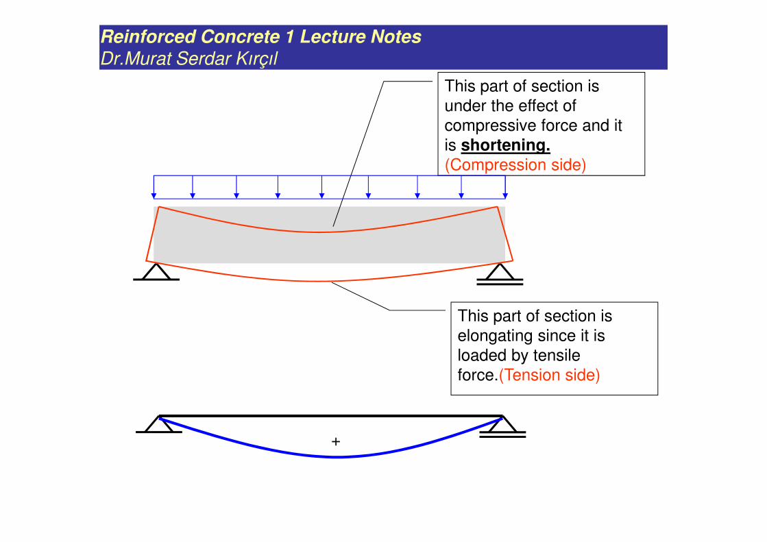
This part of section is
elongating since it is
loaded by tensile
force.(Tension side)
This part of section is
under the effect of
compressive force and it
is shortening. (Compression side)
+
Reinforced Concrete 1 Lecture Notes
Dr.Murat Serdar Kırçıl
Betonarme 1 Ders Notları
Yrd.Doç.Dr.Murat Serdar Kırçıl
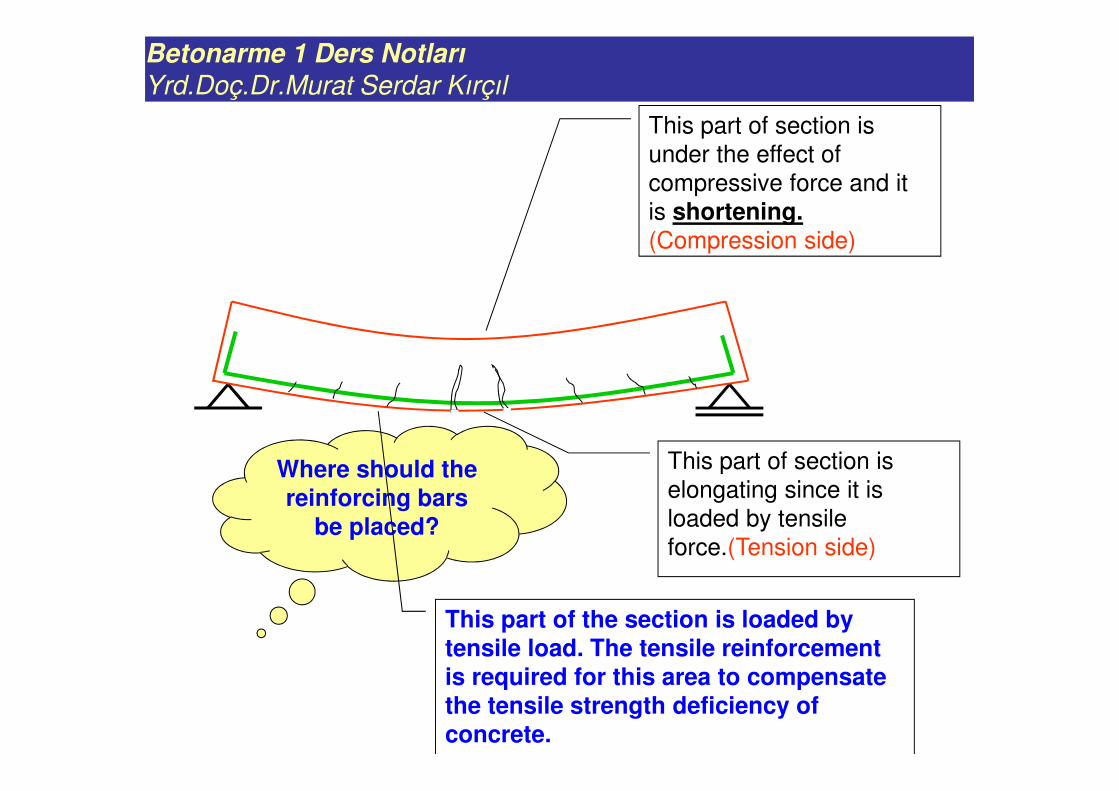
Where should the reinforcing bars
be placed?
This part of the section is loaded by tensile load. The tensile reinforcement is required for this area to compensate the tensile strength deficiency of concrete.
This part of section is
under the effect of
compressive force and it
is shortening. (Compression side)
This part of section is
elongating since it is
loaded by tensile
force.(Tension side)
Betonarme 1 Ders Notları
Yrd.Doç.Dr.Murat Serdar Kırçıl
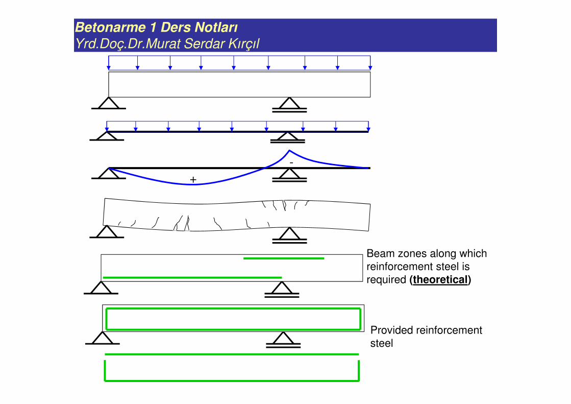
+
-
Beam zones along which
reinforcement steel is
required (theoretical)
Provided reinforcement
steel
Betonarme 1 Ders Notları
Yrd.Doç.Dr.Murat Serdar Kırçıl
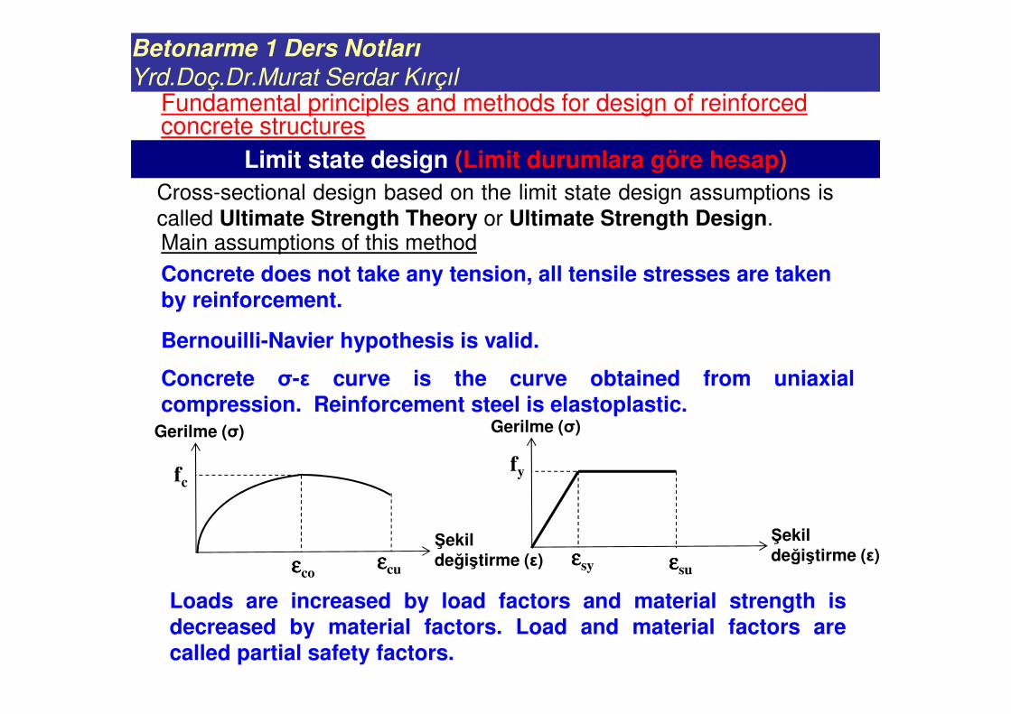
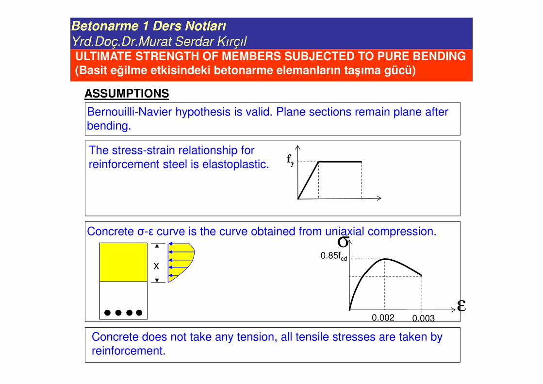
Cross-sectional design based on the limit state design assumptions is
called Ultimate Strength Theory or Ultimate Strength Design.
Concrete does not take any tension, all tensile stresses are taken by reinforcement.
Bernouilli-Navier hypothesis is valid.
Concrete σ-ε curve is the curve obtained from uniaxialcompression. Reinforcement steel is elastoplastic.
fc
εεεεcoεεεεcu
Gerilme (σ)
Şekil değiştirme (ε)
fy
εεεεsy εεεεsu
Gerilme (σ)
Şekil değiştirme (ε)
Loads are increased by load factors and material strength isdecreased by material factors. Load and material factors arecalled partial safety factors.
Limit state design (Limit durumlara göre hesap)
Fundamental principles and methods for design of reinforced concrete structures
Main assumptions of this method
Betonarme 1 Ders Notları
Yrd.Doç.Dr.Murat Serdar Kırçıl
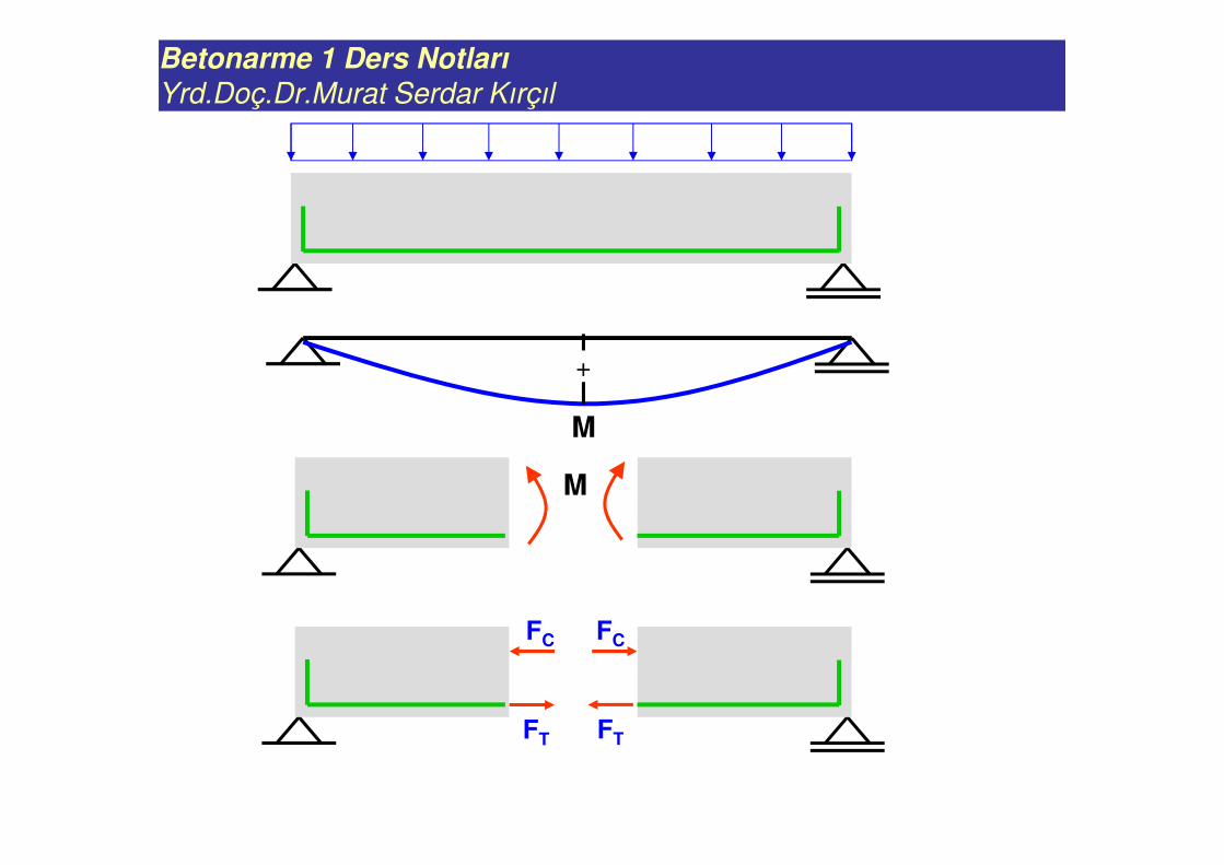
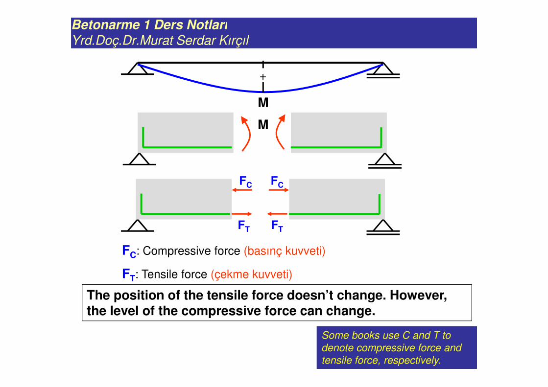
M
+
M
FC FC
FT FT
Betonarme 1 Ders Notları
Yrd.Doç.Dr.Murat Serdar Kırçıl
M
+
M
FC FC
FT FT
The position of the tensile force doesn’t change. However, the level of the compressive force can change.
Some books use C and T to
denote compressive force and
tensile force, respectively.
FC: Compressive force (basınç kuvveti)
FT: Tensile force (çekme kuvveti)
Betonarme 1 Ders Notları
Yrd.Doç.Dr.Murat Serdar Kırçıl
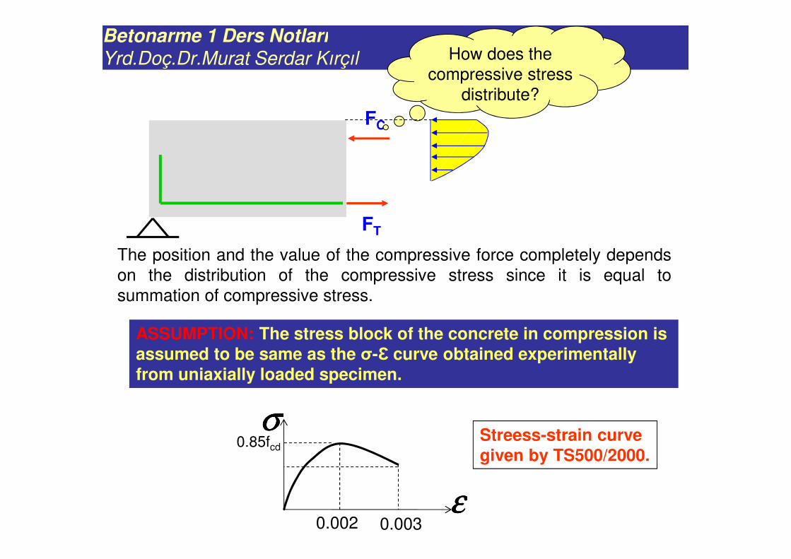
FC
FT
How does the
compressive stress
distribute?
The position and the value of the compressive force completely depends
on the distribution of the compressive stress since it is equal to
summation of compressive stress.
ASSUMPTION: The stress block of the concrete in compression is assumed to be same as the σ-Ɛ curve obtained experimentally from uniaxially loaded specimen.
σσσσ
εεεε
0.85fcd
0.002 0.003
Streess-strain curve given by TS500/2000.
Betonarme 1 Ders Notları
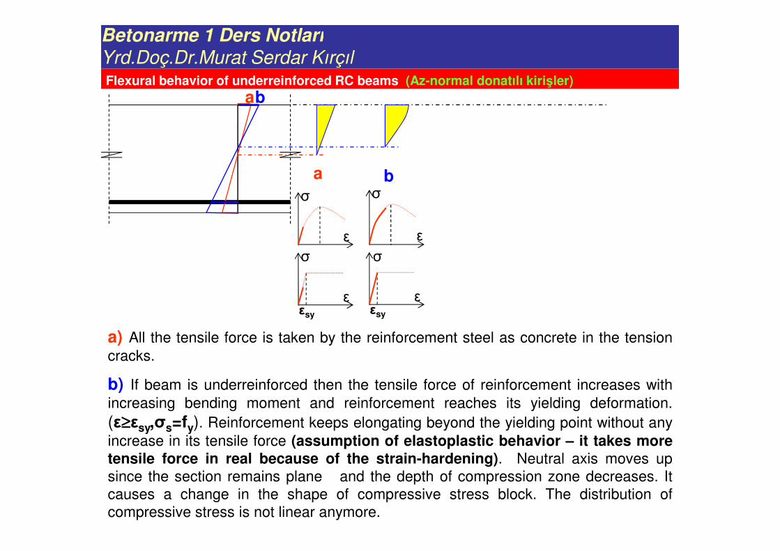
Yrd.Doç.Dr.Murat Serdar KırçılFlexural behavior of underreinforced RC beams (Az-normal donatılı kirişler)
ab
a bσ
ε
σ
ε
a) All the tensile force is taken by the reinforcement steel as concrete in the tension
cracks.
b) If beam is underreinforced then the tensile force of reinforcement increases with
increasing bending moment and reinforcement reaches its yielding deformation.
(ε≥≥≥≥εsy,σs=fy). Reinforcement keeps elongating beyond the yielding point without any
increase in its tensile force (assumption of elastoplastic behavior – it takes moretensile force in real because of the strain-hardening). Neutral axis moves up
since the section remains plane and the depth of compression zone decreases. It
causes a change in the shape of compressive stress block. The distribution of
compressive stress is not linear anymore.
σ
εεsy
εεsy
σ
Betonarme 1 Ders Notları
Yrd.Doç.Dr.Murat Serdar Kırçıl
abcd
a b c d
σ
ε
σ
ε
σ
ε
σ
ε0.003σ
εεsy
εεsy
σ
εεsy
σ
εεsy
σ
0.85fcd 0.85fcd
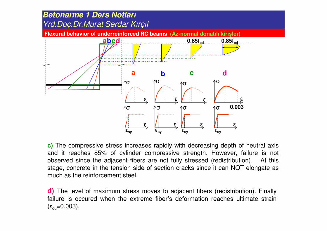
c) The compressive stress increases rapidly with decreasing depth of neutral axis
and it reaches 85% of cylinder compressive strength. However, failure is not
observed since the adjacent fibers are not fully stressed (redistribution). At this
stage, concrete in the tension side of section cracks since it can NOT elongate as
much as the reinforcement steel.
d) The level of maximum stress moves to adjacent fibers (redistribution). Finally
failure is occured when the extreme fiber’s deformation reaches ultimate strain
(εcu=0.003).
Flexural behavior of underreinforced RC beams (Az-normal donatılı kirişler)
Betonarme 1 Ders Notları
Yrd.Doç.Dr.Murat Serdar Kırçıl
abcd
a b c d
σ
ε
σ
ε
σ
ε
σ
ε0.003σ
εεsy
εεsy
σ
εεsy
σ
εεsy
σ
0.85fcd 0.85fcd
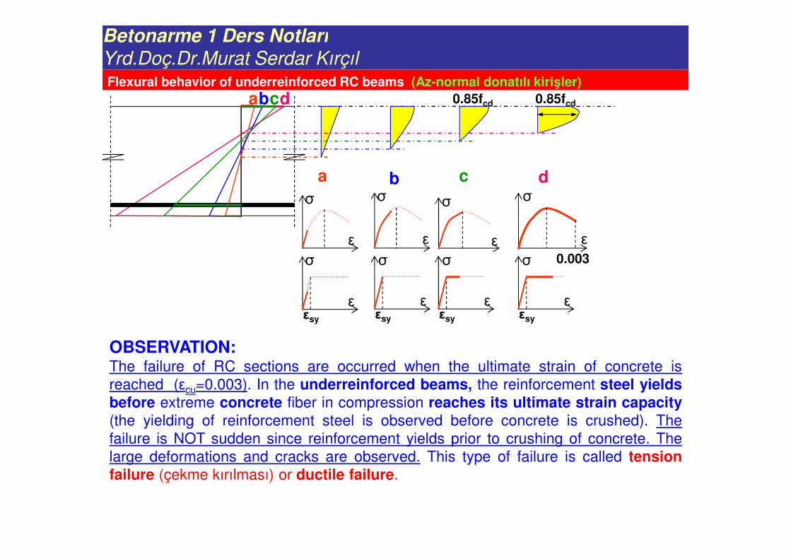
OBSERVATION:The failure of RC sections are occurred when the ultimate strain of concrete is
reached (εcu=0.003). In the underreinforced beams, the reinforcement steel yieldsbefore extreme concrete fiber in compression reaches its ultimate strain capacity(the yielding of reinforcement steel is observed before concrete is crushed). The
failure is NOT sudden since reinforcement yields prior to crushing of concrete. The
large deformations and cracks are observed. This type of failure is called tensionfailure (çekme kırılması) or ductile failure.
Flexural behavior of underreinforced RC beams (Az-normal donatılı kirişler)
Betonarme 1 Ders Notları
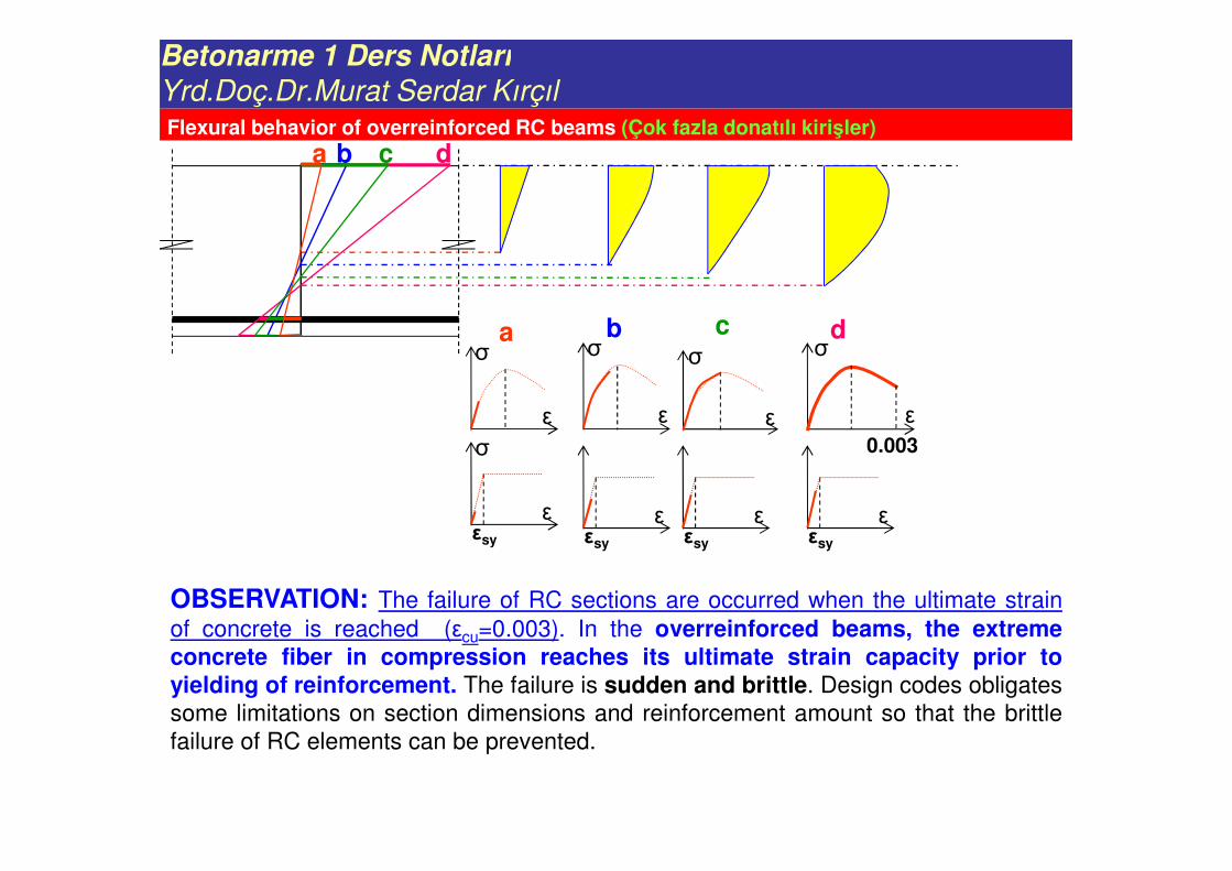
Yrd.Doç.Dr.Murat Serdar KırçılFlexural behavior of overreinforced RC beams (Çok fazla donatılı kirişler)
a b
a bσ
ε
σ
ε
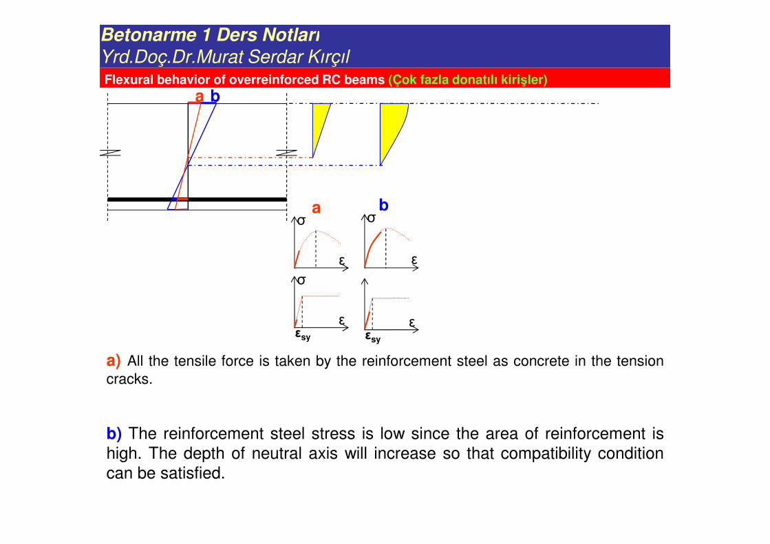
a) All the tensile force is taken by the reinforcement steel as concrete in the tension
cracks.
b) The reinforcement steel stress is low since the area of reinforcement is
high. The depth of neutral axis will increase so that compatibility condition
can be satisfied.
σ
εεsy
εεsy
Betonarme 1 Ders Notları
Yrd.Doç.Dr.Murat Serdar Kırçıl
a b c d
a b c dσ
ε
σ
ε
σ
ε
σ
ε0.003σ
εεsy
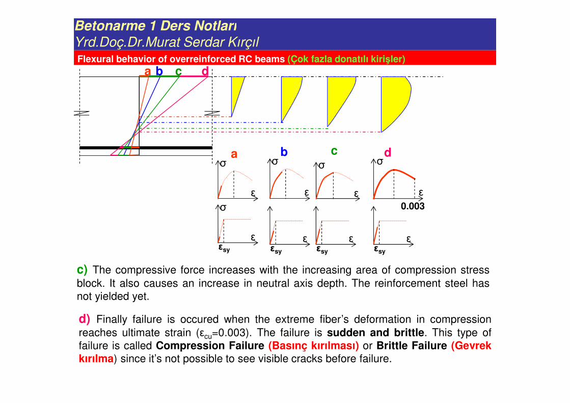
c) The compressive force increases with the increasing area of compression stress
block. It also causes an increase in neutral axis depth. The reinforcement steel has
not yielded yet.
d) Finally failure is occured when the extreme fiber’s deformation in compression
reaches ultimate strain (εcu=0.003). The failure is sudden and brittle. This type of
failure is called Compression Failure (Basınç kırılması) or Brittle Failure (Gevrekkırılma) since it’s not possible to see visible cracks before failure.
εεsy
εεsy
εεsy
Flexural behavior of overreinforced RC beams (Çok fazla donatılı kirişler)
Betonarme 1 Ders Notları
Yrd.Doç.Dr.Murat Serdar Kırçıl
a b c d
a b c dσ
ε
σ
ε
σ
ε
σ
ε0.003σ
εεsy
OBSERVATION: The failure of RC sections are occurred when the ultimate strain
of concrete is reached (εcu=0.003). In the overreinforced beams, the extremeconcrete fiber in compression reaches its ultimate strain capacity prior toyielding of reinforcement. The failure is sudden and brittle. Design codes obligates
some limitations on section dimensions and reinforcement amount so that the brittle
failure of RC elements can be prevented.
εεsy
εεsy
εεsy
Flexural behavior of overreinforced RC beams (Çok fazla donatılı kirişler)
Betonarme 1 Ders Notları
Yrd.Doç.Dr.Murat Serdar Kırçıl
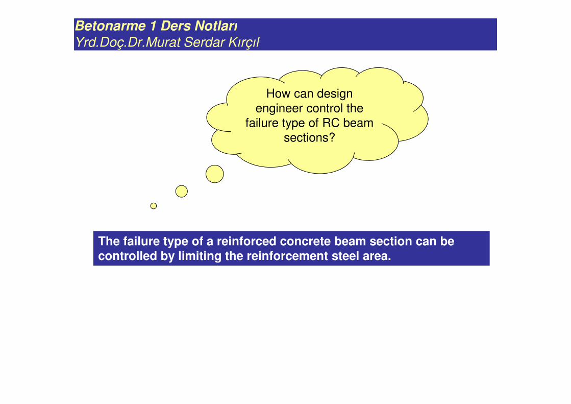
How can design
engineer control the
failure type of RC beam
sections?
The failure type of a reinforced concrete beam section can be controlled by limiting the reinforcement steel area.
Betonarme 1 Ders Notları
Yrd.Doç.Dr.Murat Serdar Kırçıl
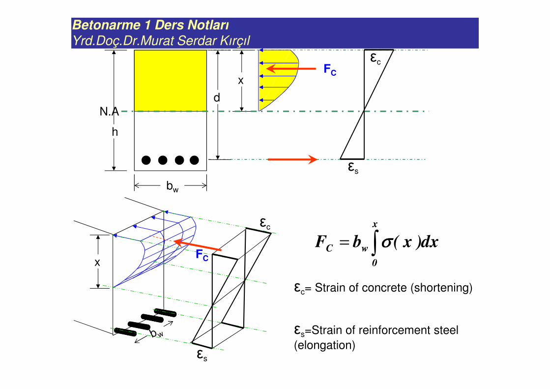
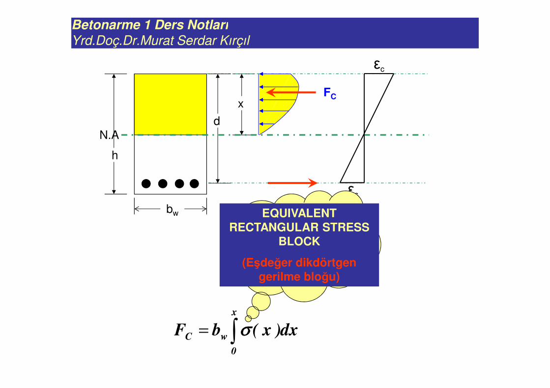
x
N.Ad
εs
εcFC
h
bw
∫=x
0
wC dx)x(bF σσσσεc
x
εs
FC
εc= Strain of concrete (shortening)
εs=Strain of reinforcement steel
(elongation)
εc
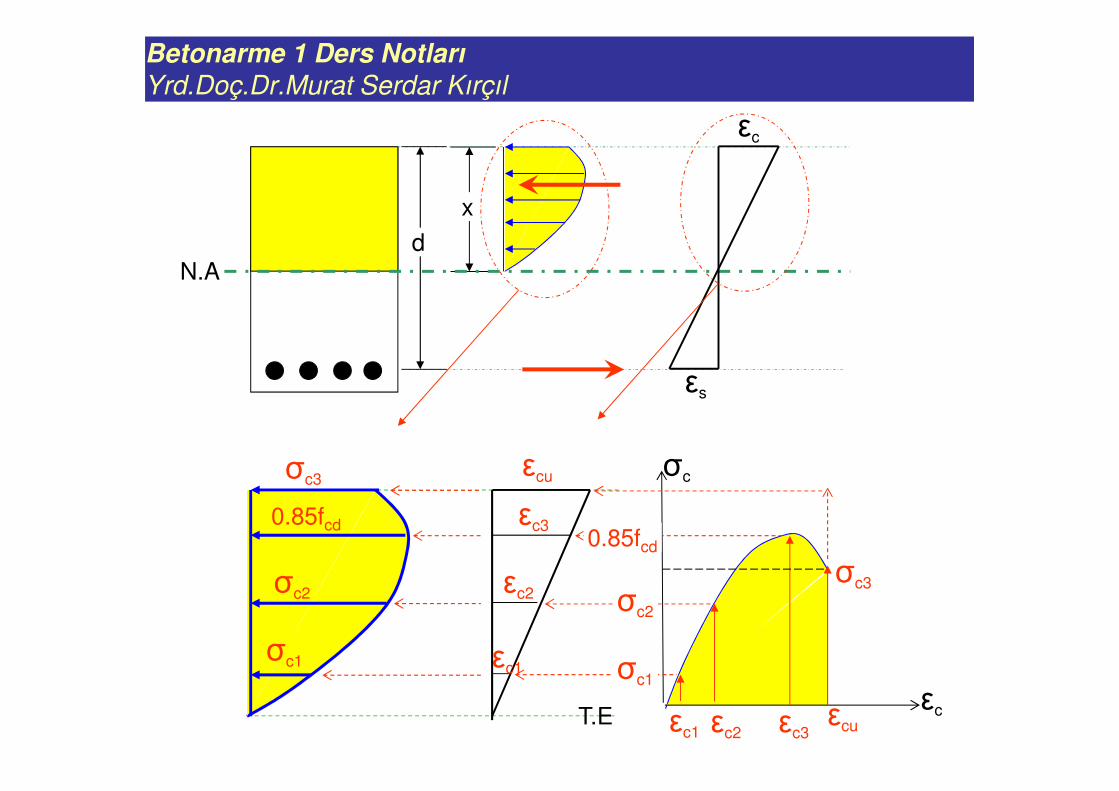
Betonarme 1 Ders Notları
Yrd.Doç.Dr.Murat Serdar Kırçıl
x
N.A
d
εs
εc
σc
εc1
εc1 σc1
σc1
σc2
0.85fcd
σc3
εc2
εc2 σc2
εc3
εc3εcu
0.85fcd
εcu
σc3
T.E
Betonarme 1 Ders Notları
Yrd.Doç.Dr.Murat Serdar Kırçıl
x
N.Ad
εs
εc
FC
h
bw
∫=x
0
wC dx)x(bF σσσσ
Is there simpler
way to calculate
the compression
force instead of
integration?
EQUIVALENT RECTANGULAR STRESS
BLOCK
(Eşdeğer dikdörtgen gerilme bloğu)
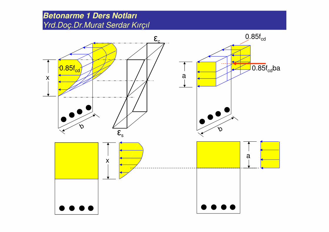
Betonarme 1 Ders Notları
Yrd.Doç.Dr.Murat Serdar Kırçıl
0.85fcd
a
a
x
0.85fcd
x
εs
εc
0.85fcdba
Betonarme 1 Ders Notları
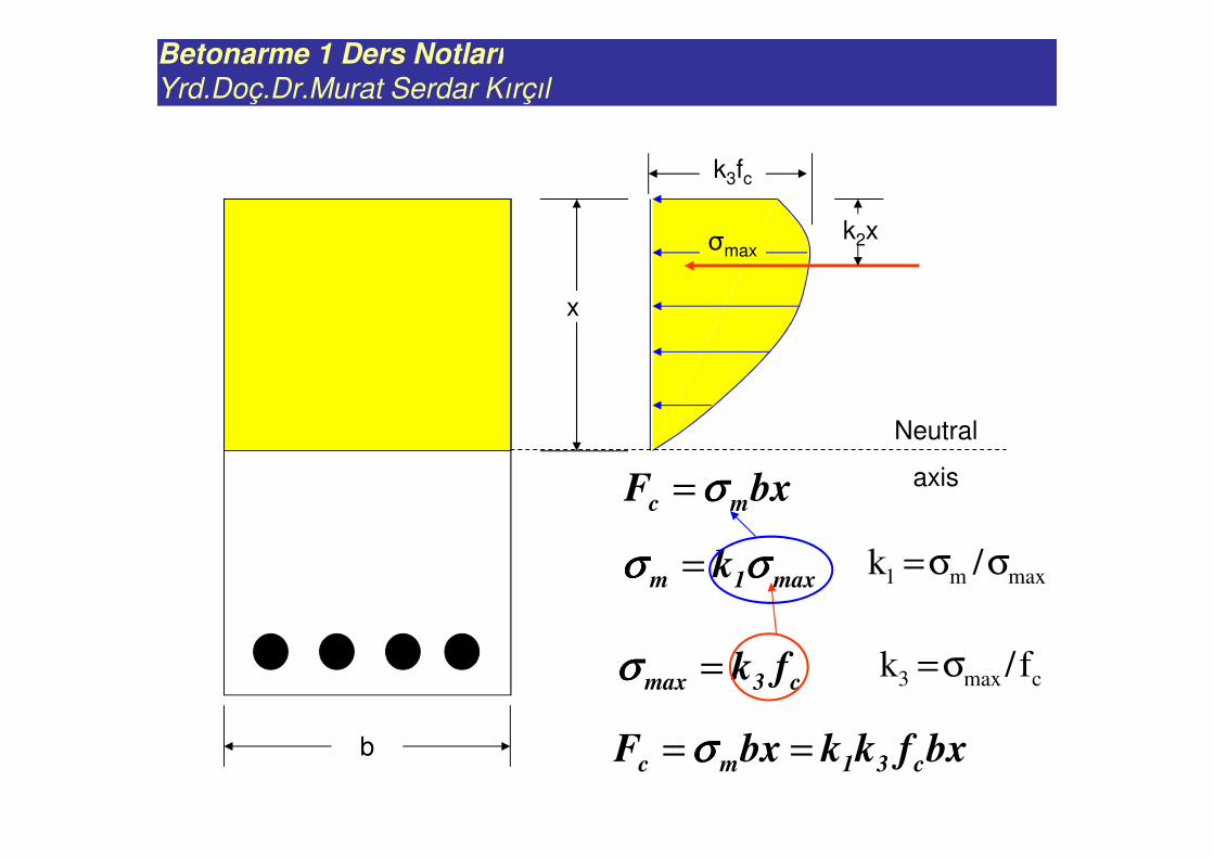
Yrd.Doç.Dr.Murat Serdar Kırçıl
x
k3fc
Neutral
axis
k2x
b bxfkkbxF c31mc == σσσσ
bxF mc σσσσ=
max1m k σσσσσσσσ =
c3max fk=σσσσ
σmax
maxm1 /k σσ=
cmax3 f/k σ=
Betonarme 1 Ders Notları
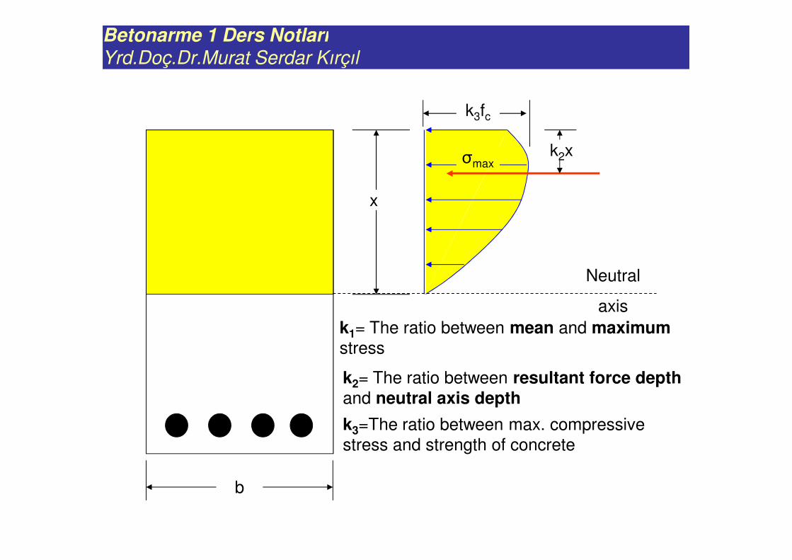
Yrd.Doç.Dr.Murat Serdar Kırçıl
x
k3fc
Neutral
axis
k2x
b
σmax
k1= The ratio between mean and maximumstress
k2= The ratio between resultant force depth and neutral axis depth
k3=The ratio between max. compressive
stress and strength of concrete
Betonarme 1 Ders Notları
Yrd.Doç.Dr.Murat Serdar Kırçıl
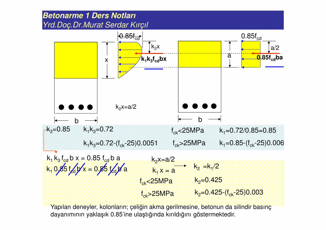
a
0.85fcd
x
0.85fcd
Yapılan deneyler, kolonların; çeliğin akma gerilmesine, betonun da silindir basınç
dayanımının yaklaşık 0.85’ine ulaştığında kırıldığını göstermektedir.
k3=0.85 k1k3=0.72
k1k3=0.72-(fck-25)0.0051
fck<25MPa
fck>25MPa
k1=0.72/0.85=0.85
k1=0.85-(fck-25)0.006
k1k3fcdbx
k2x a/2
k2x=a/2
0.85fcdba
b b
k1 k3 fcd b x = 0.85 fcd b a
k1 0.85 fcd b x = 0.85 fcd b a k1 x = a
k2x=a/2k2 =k1/2
k2=0.425
k2=0.425-(fck-25)0.003
fck<25MPa
fck>25MPa
Betonarme 1 Ders Notları
Yrd.Doç.Dr.Murat Serdar Kırçıl
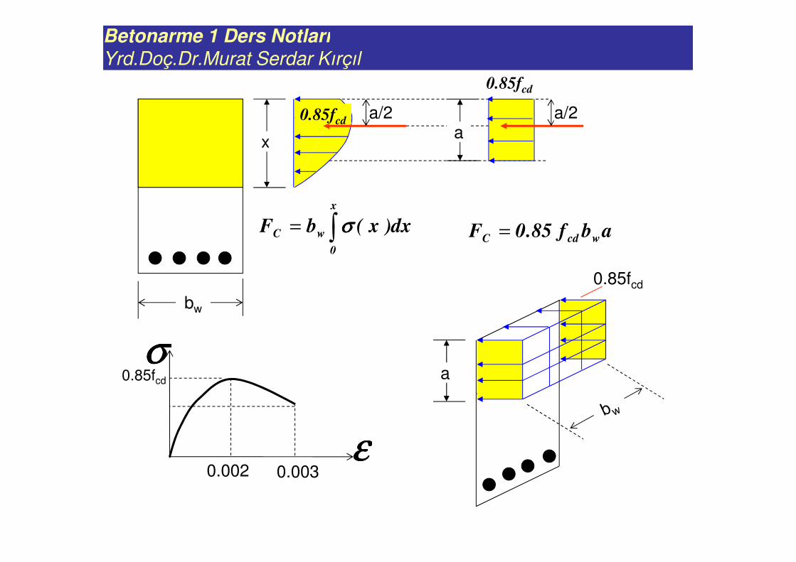
ax
a/2a/2
∫=x
0
wC dx)x(bF σσσσ
0.85fcd
σσσσ
εεεε
0.85fcd
0.002 0.003
0.85fcd
abf85.0F wcdC =
0.85fcd
a
bw
Betonarme 1 Ders Notları
Yrd.Doç.Dr.Murat Serdar Kırçıl
Concrete does not take any tension, all tensile stresses are taken by
reinforcement.
Bernouilli-Navier hypothesis is valid. Plane sections remain plane after
bending.
ASSUMPTIONS
The stress-strain relationship for
reinforcement steel is elastoplastic. fy
Concrete σ-ε curve is the curve obtained from uniaxial compression.
x
σ
ε
0.85fcd
0.002 0.003
ULTIMATE STRENGTH OF MEMBERS SUBJECTED TO PURE BENDING(Basit eğilme etkisindeki betonarme elemanların taşıma gücü)
Betonarme 1 Ders Notları
Yrd.Doç.Dr.Murat Serdar Kırçıl
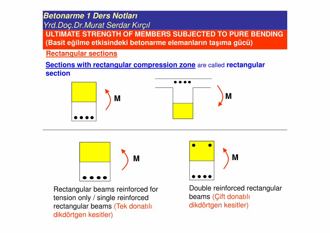
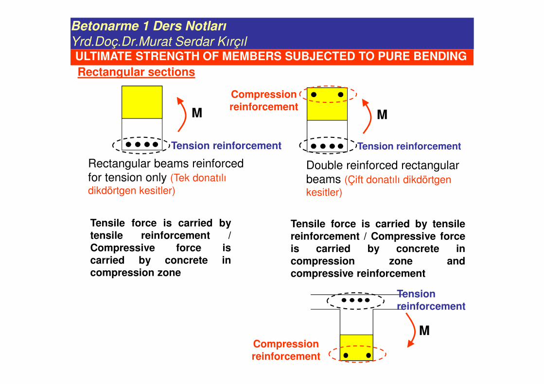
Rectangular sections
Sections with rectangular compression zone are called rectangular section
M M
M
Rectangular beams reinforced for
tension only / single reinforced
rectangular beams (Tek donatılı
dikdörtgen kesitler)
M
Double reinforced rectangular
beams (Çift donatılı
dikdörtgen kesitler)
ULTIMATE STRENGTH OF MEMBERS SUBJECTED TO PURE BENDING(Basit eğilme etkisindeki betonarme elemanların taşıma gücü)
Betonarme 1 Ders Notları
Yrd.Doç.Dr.Murat Serdar Kırçıl
M
Rectangular beams reinforced
for tension only (Tek donatılı
dikdörtgen kesitler)
M
Double reinforced rectangular
beams (Çift donatılı dikdörtgen
kesitler)
Tensile force is carried bytensile reinforcement /Compressive force iscarried by concrete incompression zone
Tensile force is carried by tensilereinforcement / Compressive forceis carried by concrete incompression zone andcompressive reinforcement
Compression reinforcement
Tension reinforcement
M
Tension reinforcement
Compression reinforcement
Rectangular sections
ULTIMATE STRENGTH OF MEMBERS SUBJECTED TO PURE BENDING
Tension reinforcement
Betonarme 1 Ders Notları
Yrd.Doç.Dr.Murat Serdar Kırçıl
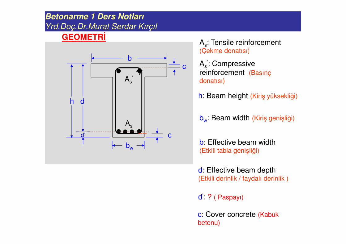
GEOMETRİ
b
bw
d
d’
h
As’
As
c
c
As: Tensile reinforcement (Çekme donatısı)
As’: Compressive
reinforcement (Basınç
donatısı)
bw: Beam width (Kiriş genişliği)
h: Beam height (Kiriş yüksekliği)
b: Effective beam width (Etkili tabla genişliği)
c: Cover concrete (Kabuk
betonu)
d’: ? ( Paspayı)
d: Effective beam depth (Etkili derinlik / faydalı derinlik )
Betonarme 1 Ders Notları
Yrd.Doç.Dr.Murat Serdar Kırçıl
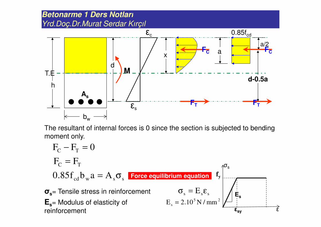
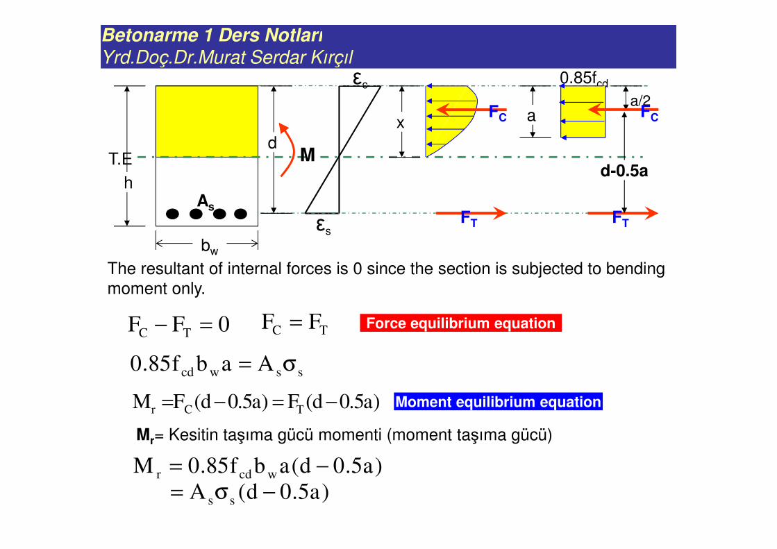
T.Ed
εs
εc
h
bw
0FF TC =−
xFC
FT
a
0.85fcd
a/2FC
FT
d-0.5aM
The resultant of internal forces is 0 since the section is subjected to bending
moment only.
sswcd Aabf85.0 σ=
TC FF =
Force equilibrium equation
As
σs= Tensile stress in reinforcement sss E ε=σ
Es= Modulus of elasticity of
reinforcement
25
s mm/N10.2E =
fy
εεsy
σs
Es
Betonarme 1 Ders Notları
Yrd.Doç.Dr.Murat Serdar Kırçıl
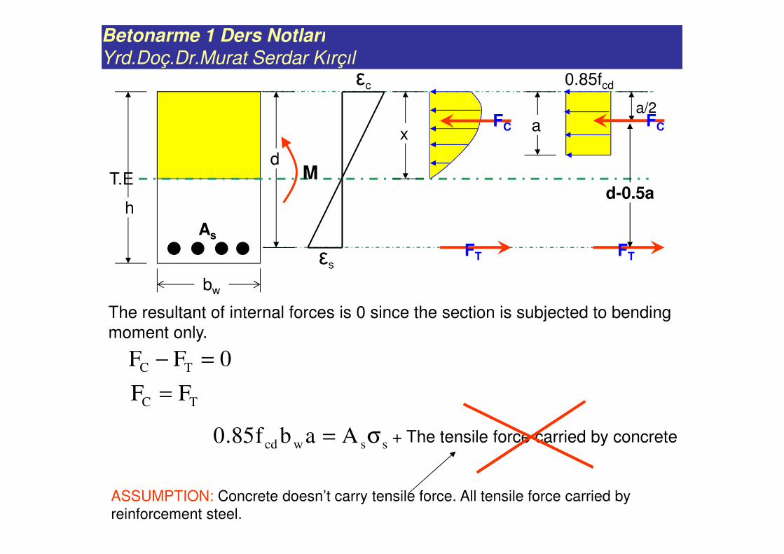
T.Ed
εs
εc
h
bw
0FF TC =−
xFC
FT
a
0.85fcd
a/2FC
FT
d-0.5aM
sswcd Aabf85.0 σ=
TC FF =
As
+ The tensile force carried by concrete
ASSUMPTION: Concrete doesn’t carry tensile force. All tensile force carried by
reinforcement steel.
The resultant of internal forces is 0 since the section is subjected to bending
moment only.
Betonarme 1 Ders Notları
Yrd.Doç.Dr.Murat Serdar Kırçıl
0FF TC =−
sswcd Aabf85.0 σ=
TC FF =
εs
εc
T.Ed
h
bw
xFC
FT
a
0.85fcd
a/2FC
FT
d-0.5aM
As
Moment equilibrium equation
Mr= Kesitin taşıma gücü momenti (moment taşıma gücü)
)a5.0d(abf85.0M wcdr −=)a5.0d(A ss −σ=
)a5.0d(F)a5.0d(FM TCr −=−=
The resultant of internal forces is 0 since the section is subjected to bending
moment only.
Force equilibrium equation
Betonarme 1 Ders Notları
Yrd.Doç.Dr.Murat Serdar Kırçıl
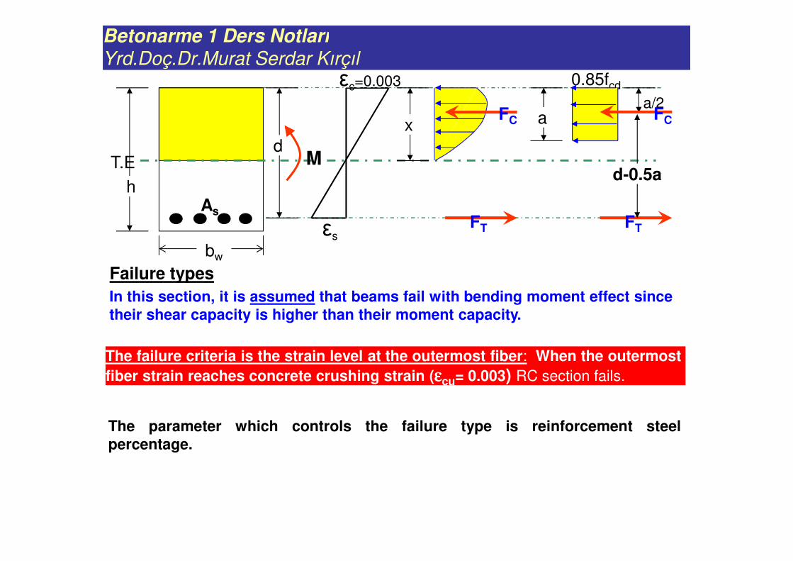
Failure types
εs
εc=0.003
T.Ed
h
bw
xFC
FT
a
0.85fcd
a/2FC
FT
d-0.5aM
As
In this section, it is assumed that beams fail with bending moment effect since their shear capacity is higher than their moment capacity.
The failure criteria is the strain level at the outermost fiber: When the outermost
fiber strain reaches concrete crushing strain (εεεεcu= 0.003) RC section fails.
The parameter which controls the failure type is reinforcement steelpercentage.
Betonarme 1 Ders Notları
Yrd.Doç.Dr.Murat Serdar Kırçıl
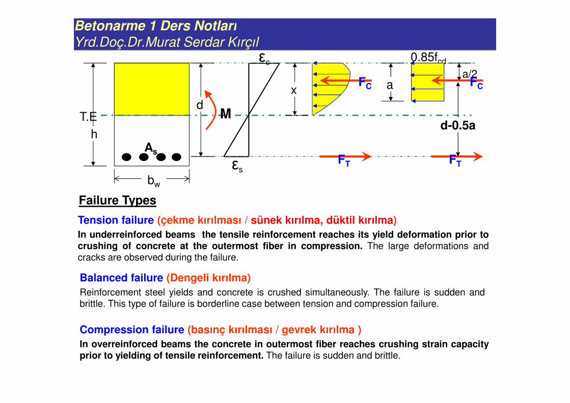
Failure Types
εs
εc
T.Ed
h
bw
xFC
FT
a
0.85fcd
a/2FC
FT
d-0.5aM
As
Tension failure (çekme kırılması / sünek kırılma, düktil kırılma)
In underreinforced beams the tensile reinforcement reaches its yield deformation prior tocrushing of concrete at the outermost fiber in compression. The large deformations andcracks are observed during the failure.
Balanced failure (Dengeli kırılma)
Reinforcement steel yields and concrete is crushed simultaneously. The failure is sudden andbrittle. This type of failure is borderline case between tension and compression failure.
Compression failure (basınç kırılması / gevrek kırılma )
In overreinforced beams the concrete in outermost fiber reaches crushing strain capacityprior to yielding of tensile reinforcement. The failure is sudden and brittle.
Betonarme 1 Ders Notları
Yrd.Doç.Dr.Murat Serdar Kırçıl
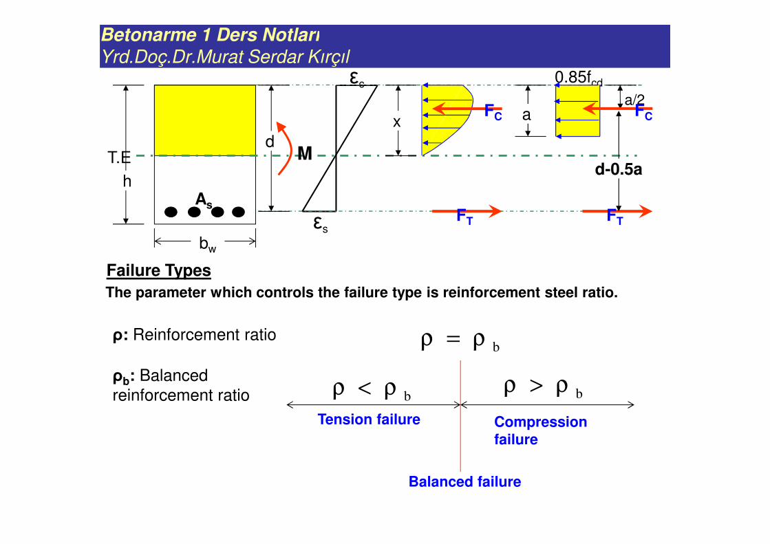
Failure Types
εs
εc
T.Ed
h
bw
xFC
FT
a
0.85fcd
a/2FC
FT
d-0.5aM
As
Tension failure
Balanced failure
Compression failure
bρ<ρ
bρ=ρ
bρ>ρ
ρ: Reinforcement ratio
ρb: Balanced
reinforcement ratio
The parameter which controls the failure type is reinforcement steel ratio.
Betonarme 1 Ders Notları
Yrd.Doç.Dr.Murat Serdar Kırçıl
sswcd Aabf85.0 σ=TC FF =
εs
εc
T.Ed
h
bw
xFC
FT
a
0.85fcd
a/2FC
FT
d-0.5aM
As
)a5.0d(abf85.0M wcdr −=)a5.0d(fA yds −=
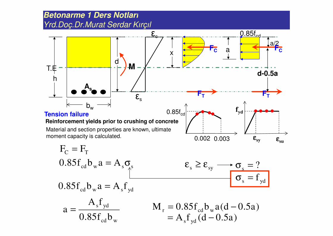
Tension failureReinforcement yields prior to crushing of concrete
0.85fcd
0.002 0.003
sys ε≥ε
fyd
εεεεsy εεεεsu
?s =σ
yds f=σydswcd fAabf85.0 =
wcd
yds
bf85.0
fAa =
Material and section properties are known, ultimate moment capacity is calculated.
Betonarme 1 Ders Notları
Yrd.Doç.Dr.Murat Serdar Kırçıl
sswcd Aabf85.0 σ=
TC FF =
εs
εc
T.Ed
h
bw
xFC
FT
a
0.85fcd
a/2FC
FT
d-0.5aM
As
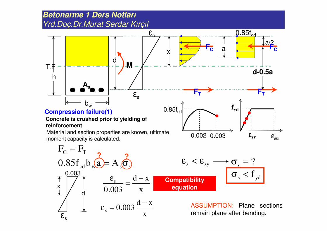
Compression failure(1) Concrete is crushed prior to yielding of reinforcement
0.85fcd
0.002 0.003
sys ε<ε
fyd
εεεεsy εεεεsu
?s =σ
yds f<σ
? ?
εs
0.003
xd
x
xd
003.0
s −=
ε
x
xd003.0s
−=ε
Compatibility equation
Material and section properties are known, ultimate moment capacity is calculated.
ASSUMPTION: Plane sections
remain plane after bending.
Betonarme 1 Ders Notları
Yrd.Doç.Dr.Murat Serdar Kırçıl
sswcd Aabf85.0 σ=TC FF =
εs
εc
T.Ed
h
bw
xFC
FT
a
0.85fcd
a/2FC
FT
d-0.5aM
As
0.85fcd
0.002 0.003
fyd
εεεεsy εεεεsu
? ?
εs
0.003
xd
x
xd003.0s
−=ε
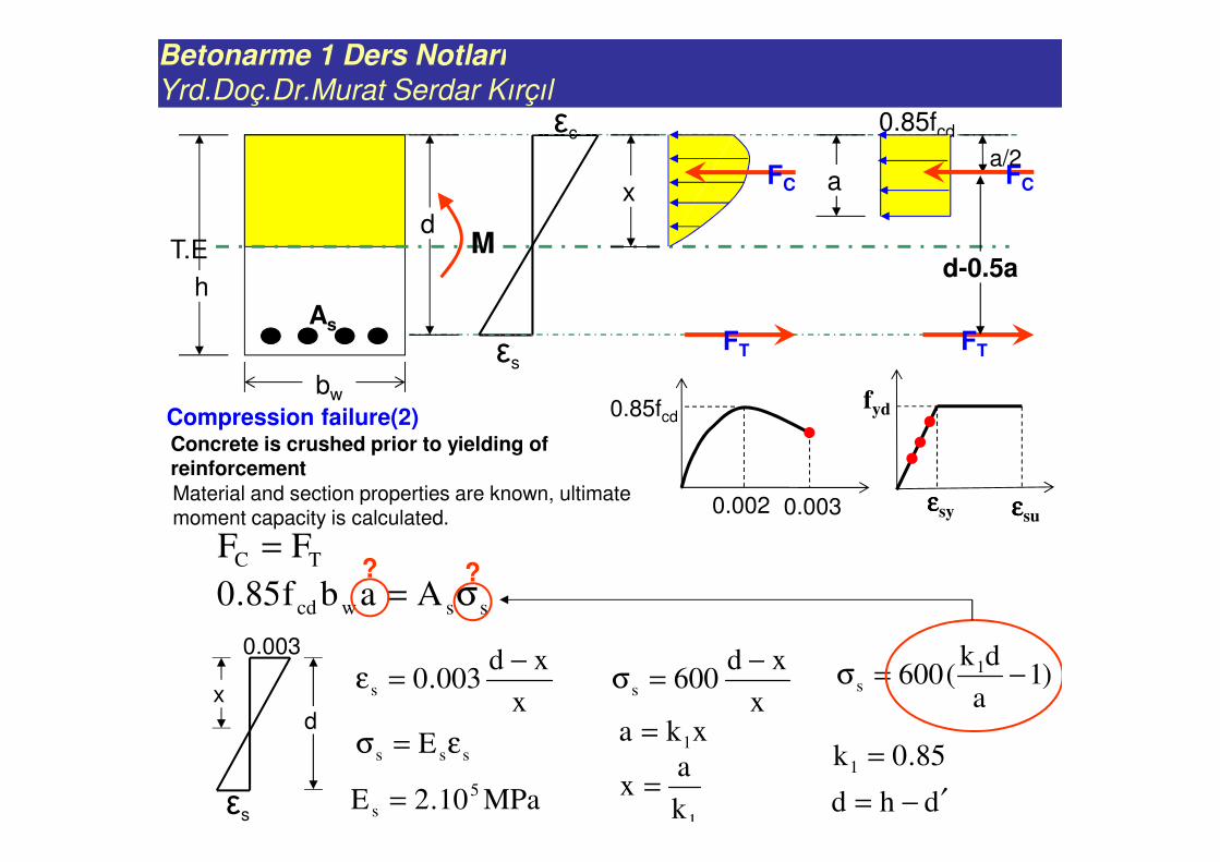
sss E ε=σ
MPa10.2E 5
s =
x
xd600s
−=σ
85.0k1 =
1k
ax =
)1a
dk(600 1
s −=σ
dhd ′−=
xka 1=
Concrete is crushed prior to yielding of reinforcement
Material and section properties are known, ultimate moment capacity is calculated.
Compression failure(2)
Betonarme 1 Ders Notları
Yrd.Doç.Dr.Murat Serdar Kırçıl
)1a
dk(600 1
s −=σ
)1a
dk(600Aabf85.0 1
swcd −=
TC FF =
εs
εc
T.Ed
h
bw
xFC
FT
a
0.85fcd
a/2FC
FT
d-0.5aM
As
)a5.0d(abf85.0M wcdr −=
)a5.0d(A ss −σ=
0.85fcd
0.002 0.003
fyd
εεεεsy εεεεsu
0dkA600a)A600(a)bf85.0( 1ss
2
wcd =−+Solve the second
order equation to
find a
s
ss
E
σ=ε
Compression failure(3)
Betonarme 1 Ders Notları
Yrd.Doç.Dr.Murat Serdar Kırçıl
ydbsbwcd fAabf85.0 =
TC FF =
εs
εc
T.Ed
h
bw
xFC
FT
a
0.85fcd
a/2FC
FT
d-0.5aM
As
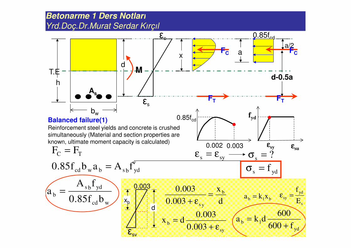
Balanced failure(1) Reinforcement steel yields and concrete is crushed simultaneously (Material and section properties are known, ultimate moment capacity is calculated)
0.85fcd
0.002 0.003
sys ε=ε
fyd
εεεεsy εεεεsu
?s =σ
d
x
003.0
003.0 b
ys
=ε+
yds f=σ
εsy
0.003
xb
d
sy
b003.0
003.0dx
ε+=
b1b xka =
yd
1bf600
600dka
+=
wcd
ydbs
bbf85.0
fAa =
s
yd
syE
f=ε
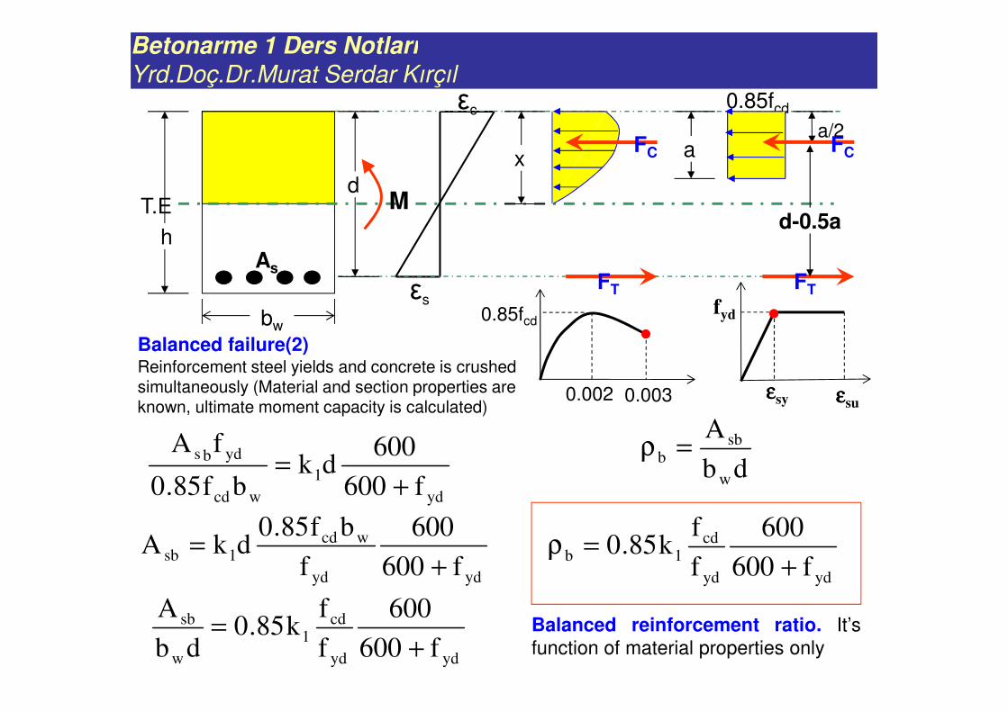
Betonarme 1 Ders Notları
Yrd.Doç.Dr.Murat Serdar Kırçıl
εs
εc
T.Ed
h
bw
xFC
FT
a
0.85fcd
a/2FC
FT
d-0.5aM
As
0.85fcd
0.002 0.003
fyd
εεεεsy εεεεsu
yd
1
wcd
ydbs
f600
600dk
bf85.0
fA
+=
ydyd
wcd1sb
f600
600
f
bf85.0dkA
+=
ydyd
cd1
w
sb
f600
600
f
fk85.0
db
A
+=
db
A
w
sbb =ρ
ydyd
cd1b
f600
600
f
fk85.0
+=ρ
Balanced reinforcement ratio. It’s
function of material properties only
Balanced failure(2) Reinforcement steel yields and concrete is crushed simultaneously (Material and section properties are known, ultimate moment capacity is calculated)
Betonarme 1 Ders Notları
Yrd.Doç.Dr.Murat Serdar Kırçıl
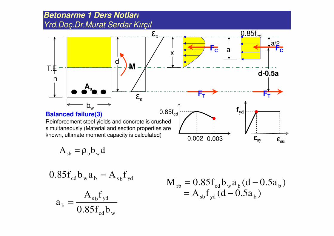
ydbsbwcd fAabf85.0 =
εs
εc
T.Ed
h
bw
xFC
FT
a
0.85fcd
a/2FC
FT
d-0.5aM
As
0.85fcd
0.002 0.003
fyd
εεεεsy εεεεsu
wcd
ydbs
bbf85.0
fAa =
dbA wbsb ρ=
)a5.0d(abf85.0M bbwcdrb −=)a5.0d(fA bydsb −=
Balanced failure(3) Reinforcement steel yields and concrete is crushed simultaneously (Material and section properties are known, ultimate moment capacity is calculated)
Betonarme 1 Ders Notları
Yrd.Doç.Dr.Murat Serdar Kırçıl
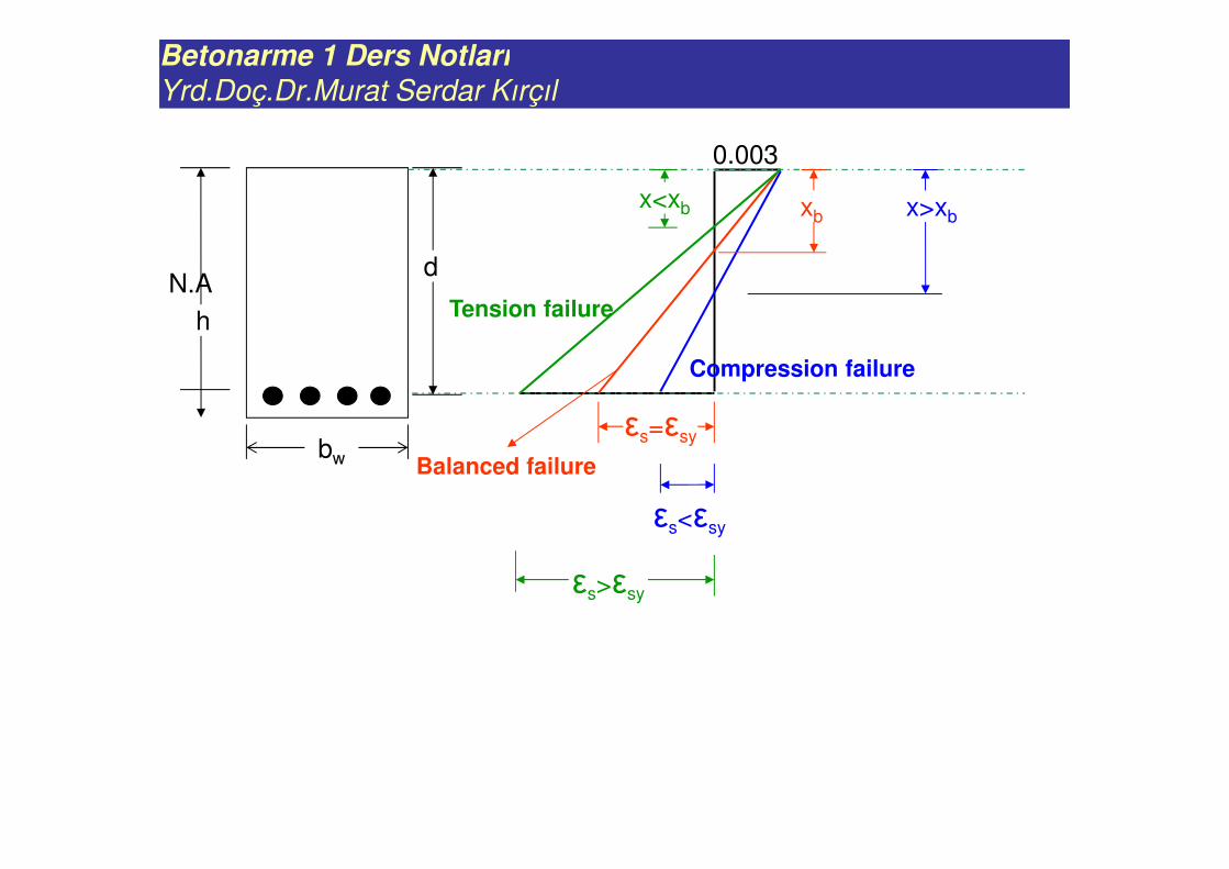
0.003
N.Ad
h
bw
Tension failure
xb
εs=εsy
εs<εsy
εs>εsy
x<xb x>xb
Balanced failure
Compression failure
Betonarme 1 Ders Notları
Yrd.Doç.Dr.Murat Serdar Kırçıl
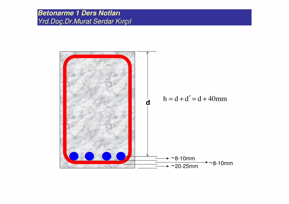
mm40dddh +=′+=d
~20-25mm~8-10mm
~8-10mm
Betonarme 1 Ders Notları
Yrd.Doç.Dr.Murat Serdar Kırçıl
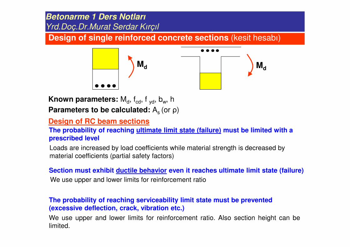
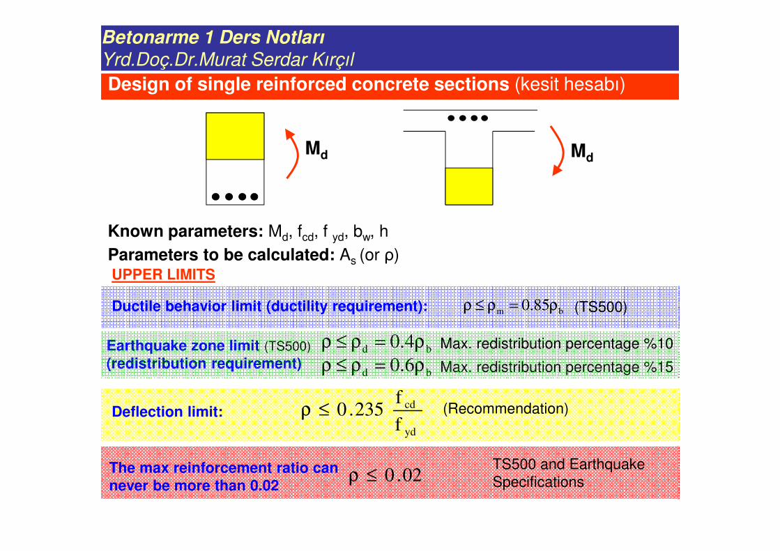
Design of single reinforced concrete sections (kesit hesabı)
Md Md
Parameters to be calculated: As (or ρ)
Design of RC beam sectionsThe probability of reaching ultimate limit state (failure) must be limited with a prescribed level
Section must exhibit ductile behavior even it reaches ultimate limit state (failure)
The probability of reaching serviceability limit state must be prevented (excessive deflection, crack, vibration etc.)
Loads are increased by load coefficients while material strength is decreased by
material coefficients (partial safety factors)
We use upper and lower limits for reinforcement ratio
We use upper and lower limits for reinforcement ratio. Also section height can be
limited.
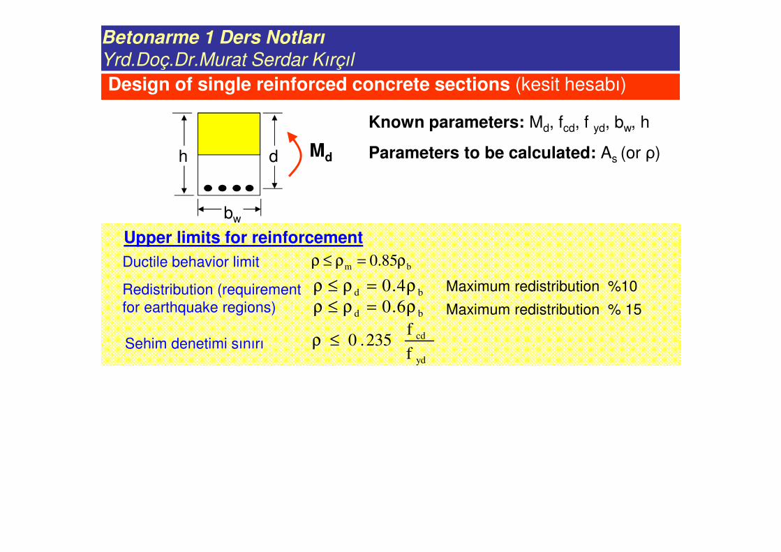
Known parameters: Md, fcd, f yd, bw, h
Betonarme 1 Ders Notları
Yrd.Doç.Dr.Murat Serdar Kırçıl
Md Md
UPPER LIMITS
bm 85.0 ρ=ρ≤ρDuctile behavior limit (ductility requirement): (TS500)
Deflection limit:
yd
cd
f
f235.0≤ρ (Recommendation)
Earthquake zone limit (TS500)
(redistribution requirement)bd 4.0 ρ=ρ≤ρ
Max. redistribution percentage %15bd 6.0 ρ=ρ≤ρ
The max reinforcement ratio can never be more than 0.02
02.0≤ρTS500 and Earthquake
Specifications
Parameters to be calculated: As (or ρ)
Known parameters: Md, fcd, f yd, bw, h
Max. redistribution percentage %10
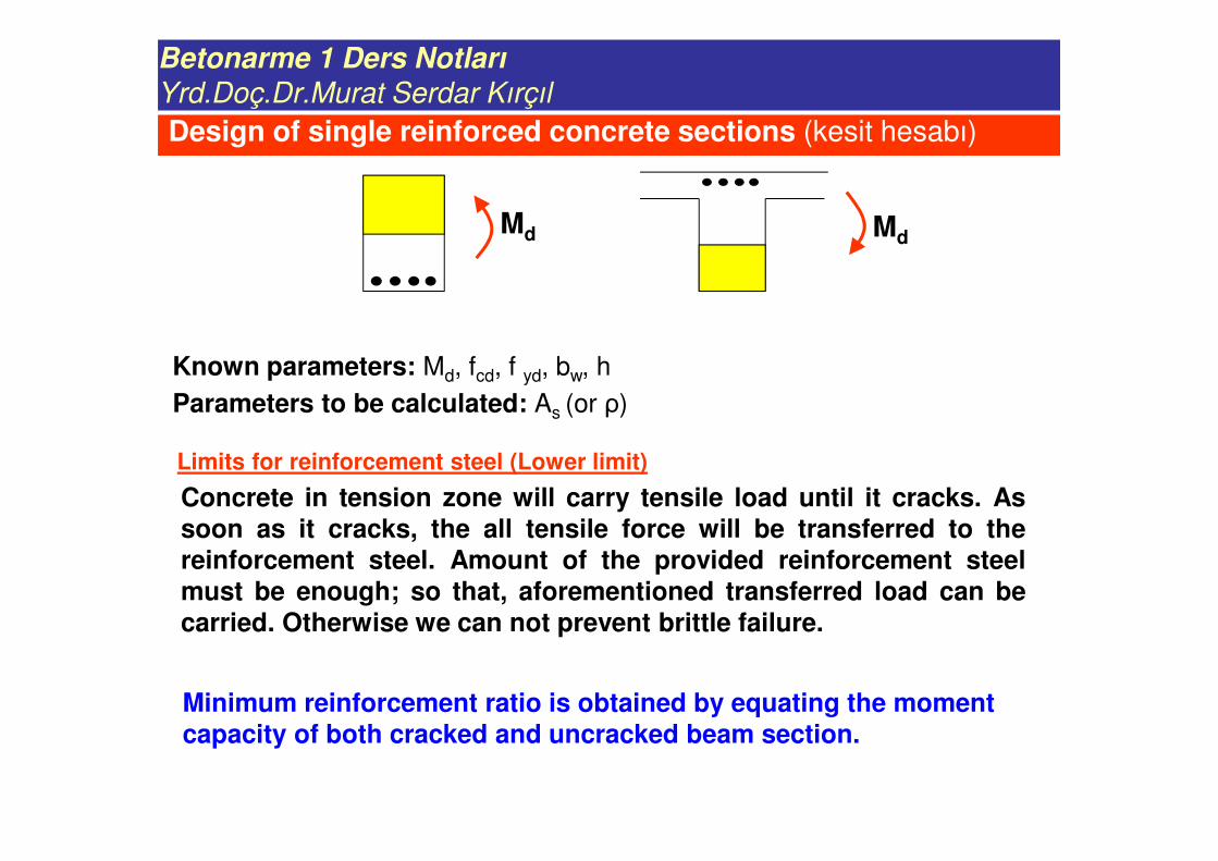
Design of single reinforced concrete sections (kesit hesabı)
Betonarme 1 Ders Notları
Yrd.Doç.Dr.Murat Serdar Kırçıl
Md Md
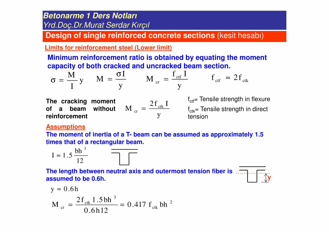
Limits for reinforcement steel (Lower limit)
Concrete in tension zone will carry tensile load until it cracks. Assoon as it cracks, the all tensile force will be transferred to thereinforcement steel. Amount of the provided reinforcement steelmust be enough; so that, aforementioned transferred load can becarried. Otherwise we can not prevent brittle failure.
Minimum reinforcement ratio is obtained by equating the moment capacity of both cracked and uncracked beam section.
Parameters to be calculated: As (or ρ)
Known parameters: Md, fcd, f yd, bw, h
Design of single reinforced concrete sections (kesit hesabı)
Betonarme 1 Ders Notları
Yrd.Doç.Dr.Murat Serdar Kırçıl
Assumptions
yI
M=σ
y
IM
σ=
y
IfM ctf
cr = ctkctf f2f ≈
fctf= Tensile strength in flexure
fctk= Tensile strength in direct
tensiony
If2M ctk
cr =The cracking momentof a beam withoutreinforcement
The moment of inertia of a T- beam can be assumed as approximately 1.5 times that of a rectangular beam.
12
bh5.1I
3
≈
yThe length between neutral axis and outermost tension fiber is assumed to be 0.6h.
2
ctk
3
ctkcr bhf417.0
12h6.0
bh5.1f2M ==
h6.0y ≈
Design of single reinforced concrete sections (kesit hesabı)
Limits for reinforcement steel (Lower limit)
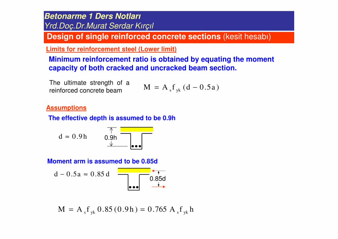
Minimum reinforcement ratio is obtained by equating the moment capacity of both cracked and uncracked beam section.
Betonarme 1 Ders Notları
Yrd.Doç.Dr.Murat Serdar Kırçıl
Assumptions
)a5.0d(fAM yks −=The ultimate strength of a
reinforced concrete beam
The effective depth is assumed to be 0.9h
h9.0d ≈
Moment arm is assumed to be 0.85d
0.9h
0.85dd85.0a5.0d ≈−
hfA765.0)h9.0(85.0fAM yksyks ==
Design of single reinforced concrete sections (kesit hesabı)
Limits for reinforcement steel (Lower limit)
Minimum reinforcement ratio is obtained by equating the moment capacity of both cracked and uncracked beam section.
Betonarme 1 Ders Notları
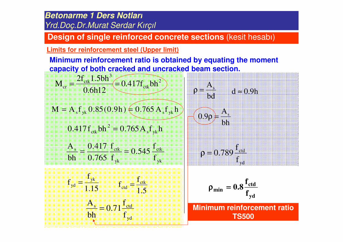
Yrd.Doç.Dr.Murat Serdar Kırçıl
2
ctk
3
ctkcr bhf417.0
12h6.0
bh5.1f2M ==
hfA765.0)h9.0(85.0fAM yksyks ==
h9.0d ≈
hfA765.0bhf417.0 yks
2
ctk =
yk
ctk
yk
ctks
f
f545.0
f
f
765.0
417.0
bh
A==
5.1
ff ctk
ctd =15.1
ff
yk
yd =
yd
ctds
f
f71.0
bh
A=
bd
As=ρ
bh
A9.0 s=ρ
yd
ctd
f
f789.0=ρ
yd
ctdmin
f
f8.0====ρρρρ
Minimum reinforcement ratio TS500
Design of single reinforced concrete sections (kesit hesabı)
Limits for reinforcement steel (Upper limit)
Minimum reinforcement ratio is obtained by equating the moment capacity of both cracked and uncracked beam section.
Betonarme 1 Ders Notları
Yrd.Doç.Dr.Murat Serdar Kırçıl
Tensile reinforcement is assumed to be yielded!
Md
bw
h d
ydswcd fAabf85.0 =
yds f=σ
)a5.0d(fAM ydsd −=
wcd
yds
bf85.0
fAa =
)bf85.0
fA5.0d(fAM
wcd
yds
ydsd −=
0M)bf(A)dbff(A)f59.0( dwcdswcdyd
2
s
2
yd =+− sA
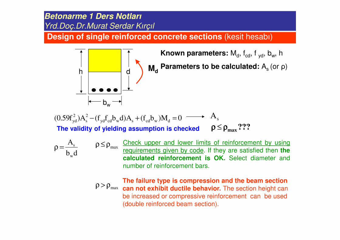
Design of single reinforced concrete sections (kesit hesabı)
Parameters to be calculated: As (or ρ)
Known parameters: Md, fcd, f yd, bw, h
Betonarme 1 Ders Notları
Yrd.Doç.Dr.Murat Serdar Kırçıl
Md
bw
h d
0M)bf(A)dbff(A)f59.0( dwcdswcdyd
2
s
2
yd =+−
The validity of yielding assumption is checked
db
A
w
s=ρ
???maxρρρρρρρρ ≤
Check upper and lower limits of reinforcement by using
requirements given by code. If they are satisfied then thecalculated reinforcement is OK. Select diameter and
number of reinforcement bars.
The failure type is compression and the beam section can not exhibit ductile behavior. The section height can
be increased or compressive reinforcement can be used
(double reinforced beam section).
maxρ≤ρ
maxρ>ρ
sA
Design of single reinforced concrete sections (kesit hesabı)
Parameters to be calculated: As (or ρ)
Known parameters: Md, fcd, f yd, bw, h
Betonarme 1 Ders Notları
Yrd.Doç.Dr.Murat Serdar Kırçıl
Md
bw
h d
Upper limits for reinforcement
bm 85.0 ρ=ρ≤ρDuctile behavior limit
Sehim denetimi sınırıyd
cd
f
f235.0≤ρ
Redistribution (requirement
for earthquake regions)bd 4.0 ρ=ρ≤ρ Maximum redistribution %10
Maximum redistribution % 15bd 6.0 ρ=ρ≤ρ
Design of single reinforced concrete sections (kesit hesabı)
Parameters to be calculated: As (or ρ)
Known parameters: Md, fcd, f yd, bw, h
Betonarme 1 Ders Notları
Yrd.Doç.Dr.Murat Serdar Kırçıl
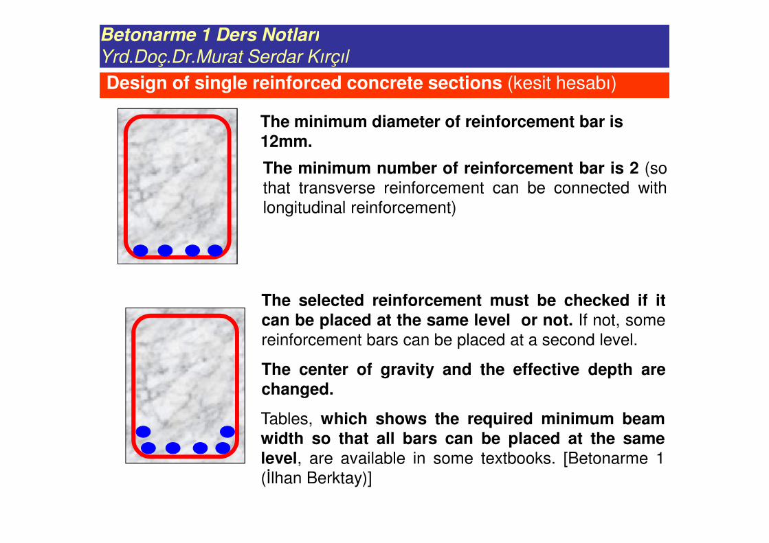
The minimum diameter of reinforcement bar is 12mm.
The minimum number of reinforcement bar is 2 (so
that transverse reinforcement can be connected with
longitudinal reinforcement)
Tables, which shows the required minimum beamwidth so that all bars can be placed at the samelevel, are available in some textbooks. [Betonarme 1
(İlhan Berktay)]
Design of single reinforced concrete sections (kesit hesabı)
The selected reinforcement must be checked if itcan be placed at the same level or not. If not, some
reinforcement bars can be placed at a second level.
The center of gravity and the effective depth arechanged.