Embed Size (px)
Citation preview

Building SolutionsAutomotive
Industry
REHAU STAR CONTROLSINSTALLATION GUIDELINES
www.rehau.co.ukValid from May 2011Subject to technical alterations


3
REHAU STAR CONTROLSCONTENTS
1 . . . . . . . . Explanation of Symbols . . . . . . . . . . . . . . . . . . . . . . 042 . . . . . . . . Safety Instructions . . . . . . . . . . . . . . . . . . . . . . . . 053 . . . . . . . . REHAU STAR Controls . . . . . . . . . . . . . . . . . . . . . . . 063.1 . . . . . . . The STAR Controls Range . . . . . . . . . . . . . . . . . . . . . . 073.2 . . . . . . . For the Installer . . . . . . . . . . . . . . . . . . . . . . . . . . 083.3 . . . . . . . For the Homeowner . . . . . . . . . . . . . . . . . . . . . . . . 094 . . . . . . . . REHAU STAR Technical Data . . . . . . . . . . . . . . . . . . . . . 104.1 . . . . . . . STAR 20 . . . . . . . . . . . . . . . . . . . . . . . . . . . . 104.2 . . . . . . . STAR 30 . . . . . . . . . . . . . . . . . . . . . . . . . . . . 114.3 . . . . . . . STAR 50 . . . . . . . . . . . . . . . . . . . . . . . . . . . . 124.4 . . . . . . . STAR Pump Relay . . . . . . . . . . . . . . . . . . . . . . . . . 134.5 . . . . . . . STAR Centre . . . . . . . . . . . . . . . . . . . . . . . . . . . 145 . . . . . . . . Overview of Main Features . . . . . . . . . . . . . . . . . . . . . 156 . . . . . . . . General Underfl oor Heating Guide . . . . . . . . . . . . . . . . . . 177 . . . . . . . . Principles of Controlling an Underfl oor Heating System (UFH) . . . . . . . 198 . . . . . . . . REHAU STAR Controls Installation . . . . . . . . . . . . . . . . . . 228.1 . . . . . . . Electrical Installation . . . . . . . . . . . . . . . . . . . . . . . . 238.2 . . . . . . . STAR Centre and STAR Pump Relay Connection and Mounting . . . . . . . . . 248.3 . . . . . . . Installer/User Setup STAR 50 . . . . . . . . . . . . . . . . . . . . . 269 . . . . . . . . Typical Specifi cation Phrases and Inclusions . . . . . . . . . . . . . . 2810. . . . . . . . Appendix . . . . . . . . . . . . . . . . . . . . . . . . . . . . 2911. . . . . . . . Notes . . . . . . . . . . . . . . . . . . . . . . . . . . . . . 30

4
1. EXPLANATIONS OF SYMBOLSHAZARD AND SAFETY INSTRUCTIONS
Application rangeThe standard controllers of the REHAU control system for heating must be used for process control and monitoring of surface heating systems only.
Correct applicationTrouble-free and safe operation of the REHAU control system for heating depends on correct transport, storage, assembly, installation and commissioning in additional to correct operation.
Electrical installationFuses, switches, wiring and grounds must be installed in accordance with the local electrical installation codes.
WiringWhen installing wiring in the 230V AC low-voltage areas must be separated to ensure segregation as defi ned in BS 76271 and also to ensure protection from electric shock.
Storage and transportThe limit values listed in the data sheets are applicable for storage and transport at all times.
Maintenance Maintenance of the REHAU control system for heating is restricted to regular cleaning. System components inside the switch cabinet and living areas are best cleaned from dust and other dirt during normal scheduled maintenance.
Installation, commissioning and maintenance of all components or the control system must be conducted by suitably qualifi ed competent engineers. All electrical installations must comply to the correct edition of BS 7671. All installation and testing must be carried out with the power disconnected and isolated.
The control components are operated by electrical current. Improper installation or improperly conducted repairs may cause death by electric shock. The devices and accessories should generally not be opened. Repairs to the device must be conducted by the manufacturer only.
Use only a dry cloth free from solvents to clean components installed in living areas.
Never touch electrical components with wet hands or cleaning cloths!
The installers have confi gured the control system for the specifi c building. Only the installers are permitted to modify the settings. Incorrect confi guration can result in ineffi cient operation of the control system even if it operates without problems otherwise or possibly undercooling of the fl oor or other areas with formation of condensation.
Please do not modify the settings. The warranty will not apply in such circumstances.
General informationPlease take the time to read this manual carefully. Although operation of the system is simple and self-explanatory, you can only take full advantage of the system when you are familiar with all the important functions of the system.
Symbols and Logos
Safety Information
Legal Information
Important Information
Information on the Web
Your Advantages
Action to be performed è

5
è Read the safety recommendations and operation instructions carefully and completely for your own safety and for the safety of other people before starting assembly.
è Retain the operating instructions and keep them handy. è If you do not understand the safety recommendations of individual assembly instructions, or if they are unclear, contact your respective REHAU sales offi ce.
Intended useThe underfl oor heating systems and system components from REHAU may only be planned, installed and operated in accordance with this technical information. Any other use is unintended and therefore impermissible.
è Observe all applicable national and international wiring, installation, accident-prevention and safety regulations when installing control systems and observe the notes in this technical information. Areas of use not dealt with in the technical information (special applications) require consultation with our applications department.
è Please contact your REHAU sales offi ce.
General precautionary measures è Observe the generally applicable accident prevention and safety regulations when installing REHAU control systems.
è Keep the work area clean and free of impeding objects. è Provide suffi cient lighting at the work areas. è Keep children, house pets, and unauthorised persons away from tools and the assembly sites. This is especially important in cases of renovation in inhabited areas.
è Use only the intended components for the respective REHAU system. The use of the components or tools from other companies which are not from the respective REHAU installation system can lead to accidents or other dangers.
Work clothing è Wear protective glasses, suitable work clothing, safety shoes, a protective helmet and gloves.
è Do not wear loose clothing or jewellery, as they can get caught by moving parts.
When assembling the system è Always read and comply with the respective operating instructions of the REHAU controls system used.
è Ensure the fl oor is controlled via a separate high limit temperature control. Details can be found in BS EN 1264. Compact mixers supplied by REHAU can be used to confi rm to this standard.
è When performing service and conversion work always isolate and test to ensure circuits are fully isolated.
NOTES OF THIS TECHNICAL INFORMATION
ApplicabilityThis technical information applies for the DIN standard and all BS, EN and hENs standards applicable.
NavigatingA detailed table of contents with hierarchical titles and the corresponding page numbers is found at the beginning of each chapter.
è Please check at regular intervals whether a more recent version of this technical information is available for your own safety and to ensure correct usage of our products. The date of issue of your technical information is always printed on the bottom right on the cover pages (e.g. 3.07 for March 2007)
- The current technical information is available from your REHAU sales offi ce, or downloadable at www.REHAU.co.uk
SAFETY INSTRUCTIONSINFORMATION ON THIS DOCUMENT
2.

6
REHAU STAR CONTROLSINSTALLATION GUIDELINES
3.
General DescriptionCost effective, easy to use, stylish and reliable, it offers the perfect solution for controlling complete underfl oor heating installations or systems combining underfl oor heating with radiators.
Although comfortable and effi cient, traditionally underfl oor heating has been slow and diffi cult to control and many of the solutions offered in the market have been complex and relatively expensive.
Now, underfl oor heating specialists REHAU are set to change all that by bringing a new range of products to the market with real ‘STAR’ quality.
Designed to operate alongside REHAU underfl oor heating pipework and manifolds and with most types of domestic boiler systems, heat pumps and solar heating, the STAR range includes standard, digital and programmable room controllers and both a wiring centre and pump/boiler module.
The range offers benefi ts for both the homeowner and the installer delivering new levels of luxurious comfort using proven, reliable technologies.
Congratulations on choosing the new range of REHAU’s STAR Controls that brings the luxury of fi ngertip control of underfl oor heating systems within the reach of every homeowner.

7
3.3.1
STAR 20Analogue Electronic Room ControllerArticle No. 206029Provides automatic temperature control to improve system effi ciency and reduce running costs. The simple dial is convenient and easy to use.
STAR 30Digital Room ControllerArticle No. 206028Featuring a large, easy to read LCD display, offers simple one touch control with integrated night set back.
STAR 50Programmable Room ControllerArticle No. 205576Choose from three pre-set profi les for separate temperature zones or use the large text display and easy navigation to set up your own.
Wiring CentreArticle No. 205578Simple plug-in system which can connect up to 6 controllers and 24 actuator units for heating requirements.
REHAU STAR CONTROLSTHE STAR CONTROLS RANGE
Pump RelayPump/Boiler logic moduleArticle No. 205579Allows the pump and boiler to have a switchable function i.e.1) Boiler fi xed on time delay2) Pump fi xed run on time
STAR Centre Plus (preassembled relay and wiring centre)Article No. 206577Simple plug in system connecting up to 6 controllers and 24 actuators complete with pump and boiler modules described earlier.

8
3.3.2
REHAU STAR CONTROLSFOR THE INSTALLER
Advanced controllers combined with a simple plug in wiring centre and boiler/pump logic module to allow you to offer customers a bespoke package of controls perfectly suited to the requirements of their individual property.
The electronic Pulse Width Modulation (PWM) system used throughout operates using a constant comparison of desired and actual temperature. The opening period of the actuators is adjusted to avoid over and under shoot, achieving more precise and comfortable control of the set point desired temperature.
Night setback which can achieve energy savings of up to 30% for homeowners is standard on all three controllers and frost protection mode is available on the digital and programmable units.
Installation of all the units is fast and straightforward. The wiring centre uses plug-in cable connections for up to 6 thermostats and 24 actuator units and the pump/boiler logic module is a simple effi ciency add on which enables the pump only to be switched on when hot water is required.
Electrical installation of the controllers must be carried out in accordance with the current wiring regulations and the connection plan. Only approved certifi ed professionals may carry out the installation.
To reduce call outs and to provide peace of mind for the user, a valve protection feature automatically opens the valves once a week to ensure that they are fully operational even when the underfl oor heating is switched on after Summer down times.
The CE approved REHAU STAR controls range has been specifi cally developed to work with underfl oor heating.

9
3.3.3
This is achieved by switching off the boiler as soon as the heating demand is satisfi ed so, the more accurately this demand can be measured, then the more effi ciently the boiler will operate.
The REHAU STAR controls system uses a system of electronic Pulse Width Modulation (PWM) to constantly compare the desired temperature with the actual temperature so that the boiler does not fi re unnecessarily and does not waste energy by over or under shooting the temperature which has been set.
Combined with a standard night set back feature on the controllers which automatically reduces the room temperature by 4ºC overnight, this can deliver energy savings of up to 30%.
The REHAU STAR controls range is easy to fi t and very easy to use. Whichever stylish surface mounted controller you choose for your home, it can be operated either with simple dial operation or push button controls
An integrated valve protection feature also opens the valves once a week to ensure that there are no problems or system failures when winter arrives.
Reliable and cost effective, the REHAU STAR controls range is the ultimate partner for a REHAU underfl oor heating system.
Underfl oor heating controls work best when they deliver luxurious comfort levels whilst also minimising the amount of energy and fuel used by the boiler.
REHAU STAR CONTROLSFOR THE HOMEOWNER

10
4.4.1
REHAU STAR TECHNICAL DATASTAR 20
AnalogueElectronic Room Temperature controller for underfl oor heating which can also be used as a standard room control systems. The controller combines the traditional with an inbuilt specifi cally developed advanced Pulse width modulated control that gives maximum control and comfort.
GeneralThe room temperature (STAR 20) controller offers key advantages over conventional mechanical products: This unique controller is easy to operate using the conventional backlit adjusting dial, when illuminated shows the room has not achieved set point.
Wiring requirements:-
Solid Wire 0.5 – 1.5mm²
Flexible Wire 1.0 – 1.5mm²
I
It is recommended that different colours are used for all electrical connections as
defi ned in the wiring regulations.
The illuminated dial gives the extra function of displaying when room set point is achieved. It also offers you unique control simplicity for heating applications of all types thanks to the high quality device electronics.
This electronic control system ensures that the set room temperature is maintained without fl uctuation and when required a time signal input automatically activates a reduction in temperature (night setback).
Technical Data STAR 20
Article No: 206029
Operating Voltage: 230VAC / 50Hz
Max. switching current: 10 (3) A
Hysteresis: 0.5K
Protection Rating: IP 30
Dimensions W/H/D: 85mm/85mm/45mm
Temperature range: 5°C - 30°C
Storage temperature: -20°C - 60°C

11
4.4.2
DigitalElectronic Room Temperature controller for underfl oor heating which can also be used as a standard room control systems. The controller combines the traditional with an inbuilt specifi cally developed advanced Pulse width modulated control that gives maximum control and comfort.
GeneralThe new REHAU room Controller (STAR 30) is a state of the art electronic room temperature controller which offers key advantages over conventional mechanical products: The control device can be easily operated by means of two buttons on the front cover.
This controller is backlit for ease of operation with a large numeric display. It also offers you unique control simplicity for heating applications of all types thanks to the high quality device electronics.
REHAU STAR TECHNICAL DATASTAR 30
Wiring requirements:-
Solid Wire 0.5 – 1.5mm²
Flexible Wire 1.0 – 1.5mm²
It is recommended that different colours are used for all electrical connections as
defi ned in the wiring regulations.
This controller ensures that the set room temperature is maintained without fl uctuation and when required a time signal input automatically activates a reduction in temperature (night setback).
The controller displays the current room temperature in stand by mode, yet one touch operates the backlight facility. For extra protection its inbuilt frost protection gives total protection for the client.
Technical Data STAR 30
Article No: 206028
Operating Voltage: 230VAC / 50Hz
Max. switching current: 10 (3) A
Hysteresis: 0.5K
Protection Rating: IP 30
Dimensions W/H/D: 85mm/85mm/45mm
Temperature range: 10°C - 35°C
Storage temperature: -20°C - 60°C
12
4.4.3
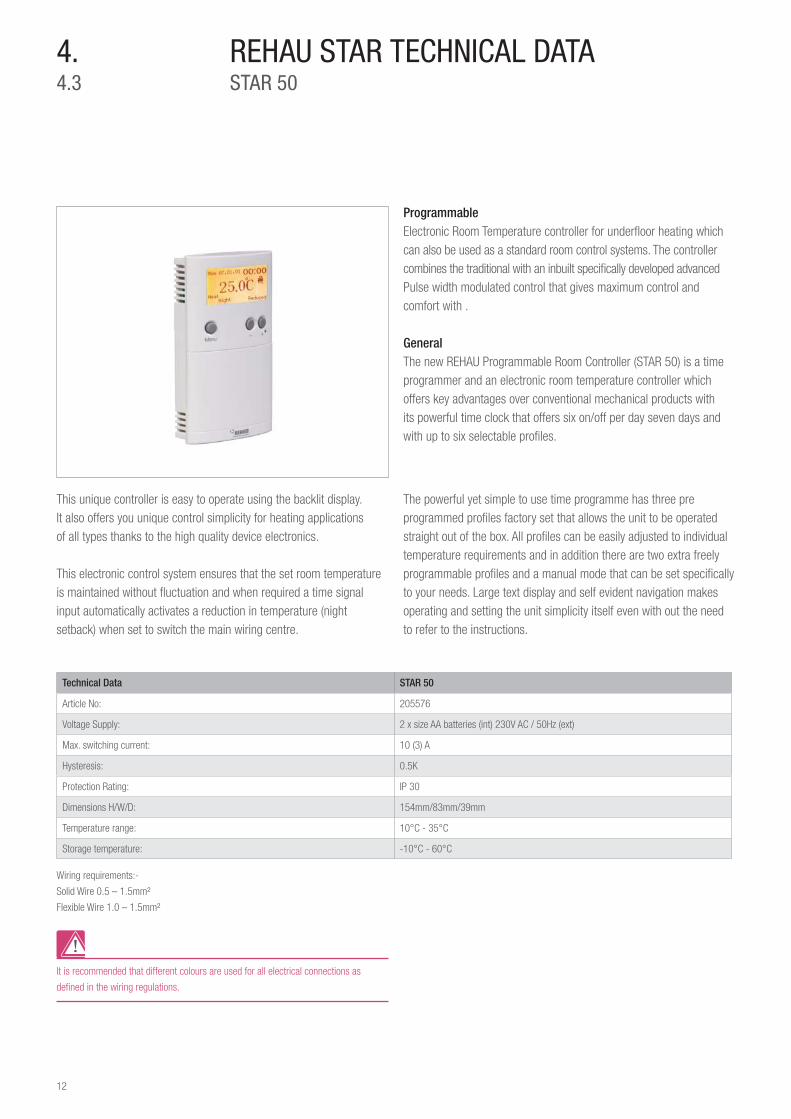
Programmable Electronic Room Temperature controller for underfl oor heating which can also be used as a standard room control systems. The controller combines the traditional with an inbuilt specifi cally developed advanced Pulse width modulated control that gives maximum control and comfort with .
GeneralThe new REHAU Programmable Room Controller (STAR 50) is a time programmer and an electronic room temperature controller which offers key advantages over conventional mechanical products with its powerful time clock that offers six on/off per day seven days and with up to six selectable profi les.
Wiring requirements:-
Solid Wire 0.5 – 1.5mm²
Flexible Wire 1.0 – 1.5mm²
It is recommended that different colours are used for all electrical connections as
defi ned in the wiring regulations.
REHAU STAR TECHNICAL DATASTAR 50
This unique controller is easy to operate using the backlit display. It also offers you unique control simplicity for heating applications of all types thanks to the high quality device electronics.
This electronic control system ensures that the set room temperature is maintained without fl uctuation and when required a time signal input automatically activates a reduction in temperature (night setback) when set to switch the main wiring centre.
The powerful yet simple to use time programme has three pre programmed profi les factory set that allows the unit to be operated straight out of the box. All profi les can be easily adjusted to individual temperature requirements and in addition there are two extra freely programmable profi les and a manual mode that can be set specifi cally to your needs. Large text display and self evident navigation makes operating and setting the unit simplicity itself even with out the need to refer to the instructions.
Technical Data STAR 50
Article No: 205576
Voltage Supply: 2 x size AA batteries (int) 230V AC / 50Hz (ext)
Max. switching current: 10 (3) A
Hysteresis: 0.5K
Protection Rating: IP 30
Dimensions H/W/D: 154mm/83mm/39mm
Temperature range: 10°C - 35°C
Storage temperature: -10°C - 60°C

13
4.4.4
- Pump OverunIt can allow the pump to have a run on time of 3 minutes once sensors have swiched off if required this function can be de activated using jumpers shown.
- Pump and Boiler DelayThis can enable boiler and pump protection, for instance it delays the turn on time for pump and boiler by three minuites after an sensor calls for heat if required this function can be de activated using jumpers shown
Boiler and Pump, Logic ModuleThis is an Intelligent electronic control interface that can switch the pump and boiler dependant on the requirements of the main wiring center. This unit is used to protect the boiler and pump and to reduce cold cycling of the boiler so as to ensure there is a demand for heat prior to switching on the boiler and pump unit.
Our experience over the years have proved that this reduce excessive energy usage and ensures better control of the Underfl oor Heating. The pump module is optional and has the following functions:
REHAU STAR TECHNICAL DATASTAR PUMP RELAY
Technical Data STAR Centre Pump Relay
Article No: 206577
Operating Voltage: 230V AC
Flexible cable 1.0 - 1.5 mm2
Solid Cable: 0.5 - 1.5 mm2
Ambient temperature: 0°C - 50°C
Storage temperature: -25°C to + 60°C
Protection Rating: IP 20
Current Rating: 3(2) A
Dimensions H/W/D: 85mm x 85mm x 38mm
Switch contact: Potential free
Jumper Function Default Setting
J2-Pump overrun time
ON -OFF
Jumper is ON (3
minute) position
ON - After all controller have switched
off the pump runs for an additional 3
minutes for boiler protection
OFF - Disables pump over run. When
all controller are switched off the
pump will also switch off immediately
as well
Jumper Function Default Setting
J1-Boiler and pump
protection ON -OFF
Jumper is ON (3
minute) position
ON -Enables boiler and pump protec-
tion (delays turning on pump and boiler
relays for 3 minutes when a controller
calls for heat)
OFF - Disables boiler and pump
protection (immediately turns pump
and boiler relays on when a controller
calls for heat

14
4.4.5
REHAU STAR TECHNICAL DATASTAR CENTRE
Wiring CentreThis is a specifi cally designed wiring centre interface that is used primarily in the control of underfl oor heating. Its inbuilt logic distributes the Night set back and time signal specifi cally to the controller, actuators and if installed the boiler/pump logic module. It can connect up to six various combinations of controllers. On the output side each zone can have a maximum of four actuators allowing in total the facility of twenty four thermal actuators.
General The wiring centre has an unique system of terminations and are easily pushed into the appropriate terminals using the insertion tool supplied with the unit.
Technical Data Wiring Centre
Article No: 205578
Operating Voltage: 230V AC
Circuit voltage: 230V AC, 5 A
Dimensions H/W/L in mm: 64 x 86.5 x 304
Safety fuse: T2A
Max. no. of controllers: up to 6
Max. no. of actuators: up to 24
Flexible cable: 1.0 - 1.5 mm2
Solid Cable: 0.5 - 1.5 mm2
Ambient temperature: 0°C to 50°C
Storage temperature: -25°C to 60°C
Relative air humidity: max 95% non condensing
Type of safety cut-out: II
Protection rating: IP20

15
Building Regulations and the EnvironmentREHAU have a commitment to assist building owners and occupiers to reduce their carbon footprint. One such way of reducing the energy used, is the effective control of heating and hot water. One way to reduce this energy is to only burn fuel when there is a demand for heat from the boiler, either for heating or hot water. When this demand is satisfi ed, then the boiler should switch off again – it should not be able to fi re until a new demand is created by the controls. This is called Boiler Interlock and represents the minimum standard required under the Building Regulations for new and existing heating systems.
Valve Protection FeatureIn order to ensure that the valves remain movable and functional even after long periods out of operation - i.e. in summer, the REHAU controller is supplied with a switchable valve exercising operation, this ensures that the valves remain functional by operating the outputeach week. This valve protection feature can be deactivated if required.
Controls are the most important pointsSpending time getting the underfl oor heating controls system right for your project will pay dividends of comfort and effi ciency long into the future. Our expertise in control systems sets us apart from our competitors.
Our controls are tried and tested by our distinguished team of experts in controls who’s main interest is client comfort, We can provide you with a range of underfl oor heating controls, from a simple manually mixed system to a highly sophisticated remote sensing and automated system, accessible via BMS and the internet.
Our Control PrinciplesWe believe that each room is unique and will therefore have its own needs, in terms of comfort and control. As a result, it’s generally good practice to combine individual room controls with overall system water temperature control.
This makes sure that you achieve the comfort you require and maximise the effi ciency of the system.
Room comfort control is normally achieved using room controllers but remember, an underfl oor heating controller or room thermostat only acts as a switch, it cannot control the heat output of the system, it can only switch it on or off.
The heat output and therefore comfort level, of the system relates directly to the system water temperature.
For increased effi ciency, we normally operate the room controller in conjunction with a setback control, which maintains the property at a core temperature during off peak periods.
Night Set BackREHAU controls offer night set back to reduce energy and this is simply set on the STAR 50 controller selecting time of operationand this sets all controls to a night or reduced mode of 4°C (fi xed).
Electronic Pulse Width ModulatingThe electronic Pulse Width Modulation (PWM) system used throughout operates using a constant comparison of desired and actual temperature. The opening period of the actuators is adjusted to avoid over and under shoot, achieving more precise and comfortable control of the set point desired temperature.
Pulse width modulation itself is a way of delivering energy through a series of pulses rather than a contiounsly varying analogue signal. By increasing and decreasing pulse widths, the controller regulates the energy fl ow to the underfl oor actuators and hence the fl oor.
Pulse Width Modulation (PWM) Since the PWM control method allows the heater on when the actual temperature is lower than the desired setting temperature, thus, PWM control method is the best intelligent temperature control method to control the slow responsive circuit.
5.OVERVIEW OF MAIN FEATURES
H
HH H
H
HH
LL L
L
High
Low

16
PWM works on a setting temperature and a cycle time. The cycle time is measured in cycles per hour (cph). PWM also uses a differential that is centered around the desired setting temperature. The system operates once per cycle to control the heater on and off in the operation “triangle” (fi gure1).
span: rate of temp changed
t: update interval
cycle
Max.temp
Settingtemp
Min.temp
Span
Figure 1
In one cycle, PWM has many update intervals. Different update intervals have different temperature. The heater on is determined by the position of the actual temperature. If the actual temperature is below the desired temperature in the particular update interval, the heater is turned on (fi gure 2). Otherwise, if the actual temperature is higher than the desired temperature, the heater is turned off. When the time is changed, it will move to other update interval, the desired temperature in new update interval is also changed. The system then uses the new desired temperature to compare the actual temperature to control the heater. Since different intervals have their desired temperature, thus the operation triangle is formed.
Setting temp.
Min. temp.
Max. temp
t: update interval
Heater off
Settingtemp
Heater on
t
Figure 2: Comparison in each update interval t.
The length of the heater on is determined the difference between the desired setting temperature and the actual temperature. If the desired setting temperature and the actual temperature is the same, the heater is turned on for 50% of cycle time. If the actual temperature is higher than the maximum setting temperature, the heater is turned on for 0% of cycle time. Therefore, the length of the heater on is determined by the change of the actual temperature.
The Δ span and span is the sensitive of the control system. If the span is large, the heater is turned even for higher actual temperature. The cycle time and update interval is the rate of heater on and off. If the cycle time is long, the heater is turned on longer for in cycle time.
To ConcludePWM is somewhat like pushing a playground-style merry-go-round.The energy of each push is stored in the inertia of the heavy platform, which accelerates gradually with harder, more frequent, or longer-lasting pushes. The riders receive the kinetic energy in a very different manner than how it’s applied.
Pulse Width Modulation0% Duty Cycle – analogWrite (0)
25% Duty Cycle – analogWrite (64)
50% Duty Cycle – analogWrite (127)
75% Duty Cycle – analogWrite (191)
100% Duty Cycle – analogWrite (255)
5v
0v
5v
0v
5v
0v
5v
0v
5v
0v

17
6.
Design LimitsBS EN 1264-2:1997 states that fl oors may be raised to a maximum of 29°C and up to 35°C in peripheral areas. For screeded fl oors with maximum design surface temperature of 29°C, the fl oor could emit 100W/m2 with an indoor temperature of 21°C.
Pipe SpacingBased on many years of design experience, REHAU established that pipes should generally be spaced at 200mm centres to achieve optimum working effi ciency. In areas of high heat loss, the pipe spacing may be decreased to 150mm.
This is a guide only and REHAU would recommend a system design.
Screed ThicknessFor solid fl oor construction, a normal fl oor screed can be used. No special additives in the screed are required. Where the pipe is laid on insulation, the minimum screed depth must be 65mm for domestic applications and 75mm for commercial applications as specifi ed in UK Building Regulations. Where heavier fl oor loadings are required, the construction engineer should advise on the screed thickness. Where special screeds are specifi ed, the manufacturer must be consulted as to the screed thickness.
Floor CoveringsREHAU must be notifi ed of the fl oor covering type before design commences.
While fl oor coverings laid above the UFH system do not normally present problems, they must be taken into consideration at the design stage to ensure that a good design is established. After installation, the UFH system can be “tuned” to match the variations in fl oor coverings from room to room by adjusting the Lockshield valves for the individual loops.
Timber Floor SurfacesCareful consideration of the type of fl oor to be laid must be established before the system is designed and installed. Particular attention should be paid to moisture content of the wooden fl oor. Consider if the timber fl oor will be fl oated on a screed or fi xed to battens. This will determine which type of UFH system will be used. Not all timber fl oors are suitable for UFH and advice should be sought from the fl ooring supplier from the trade association TRADA. Details of the British Standard BS8201 should be observed.
Glazed AreasIn most areas of a building the heat losses are relatively similar and unless very large areas of glass are used, the pipe centres do not need to vary. When designing the UFH system, the warmer fl ow pipe should be positioned to run immediately next to outside walls or other potential cold spots. This ensures a slightly higher heat output in these areas. Extensive areas of glazing in modern developments may require special design consideration. A closer pipe spacing of 150mm may be chosen.
In double height rooms, e.g. barn conversions or conservatories, the pipes may be spaced at 150mm centres. During extreme winter conditions, supplementary heating may still be required in glazed areas such as conservatories where the heat losses are excessively high.
Positioning the ManifoldsIt is important to fi x the positions of the manifolds at the beginning of the design process. The position of the manifolds should be as central as possible in order to minimise the lengths of pipe tails and unequal loop lengths. One manifold set typically serves a fl oor area up to 150–240m2.
Optimising Loop LengthsTo allow for different loop lengths, heat outputs and different fl oor coverings it is necessary to balance the loops on each manifold. In summary, the fl ow in short loops serving small rooms needs throttling relative to longer loops serving larger rooms. If the loops are not balanced, the shortest loop would “steal” all the water fl ow from the longest loops, resulting in reduced heating to the largest rooms.
To help achieve fl ow balance in the system, loop lengths are normally designed to be of similar length. To avoid many short loops serving small rooms, some areas may be linked into one operating zone, e.g. hallways, toilets and common areas. Two or more loops may be required to serve larger areas.
GENERAL UNDERFLOOR HEATING GUIDE

18
InsulationA layer of insulation should be laid immediately below the heating pipes to prevent downward heat losses. For screeded fl oors, REHAU normally supplies a plastic Clip Rail for fi xing the pipework. Clip Rail is laid onto the insulation to which the pipes are attached. This means that the client can use the insulation material of his choice to lay underneath the fi xing system.
Minimum insulation thickness and type should be specifi ed by the architect and/or builder to comply with the current Building Regulations.
Thermal Response TimeThe better the U-value of the building and the higher the degree of insulation, the faster the response time of the system.
In wooden suspended or fl oating fl oors, system response time is comparable to a radiator system. However, there is no thermal lag with these types of fl oor construction and good levels of insulation are required under these systems. Where it is necessary to allow a small gap between the insulation and the UFH system, there must be no air movement in this air gap.
Where the UFH system is to be installed in wooden suspended ground fl oors with an open void below, all air movement must be prevented between the insulation and the UFH system to ensure maximum effi ciency from the heating system.
For systems installed in screed operating on a daily basis, the response time is fast. This is because the temperature drop during “off” periods of up to 8 hours is of the order of only 3°C due to the thermal lag in the fl oor created by the energy stored in the screed. By carefully setting the system time clock, comfort can be maximised whilst minimising the system “on” time.
Sound InsulationDepending on the type of insulation installed, the insulation will provide a degree of sound insulation. If a specifi c level of sound insulation is specifi ed, details must be advised to the design team before the design process begins.

19
PRINCIPLES OF CONTROLLING AN UNDERFLOOR HEATING SYSTEM (UFH)
REHAU Underfl oor Heating REHAU Underfl oor Heating is a favoured choice for industry professionals. Practical, cost-effective and fl exible, Underfl oor heating is increasingly being specifi ed over traditional radiator systems and establishing a reputation as the preferred modern-day heating solution.
Most common are the wet systems (using warm water), though there are also electric (dry) systems available. Pipes are normally buried in the screed, or run underneath the fl oor surface. The pipes transfer heat from the (slightly warmer) fl oor into the wider room space, which is more effi cient than traditional plumber-installed radiators which transfer heat from a relatively small and very hot surface into a much larger and cooler space (the room).
Advantages - Comfort – Even spread of heat provides a high level of comfort. - Economy – reduced demand on boilers and no wasted heat at
ceiling height saves costs. - Cost-effi ciency – Reduced on-site maintenance – servicing of
boilers and pumps only. - Flexibility – Unrestricted wall surfaces in both old and new buildings. - Safety – No hazardous wall projections or hot surfaces. - Control – REHAU comprehensive controls package offers a solution
for the majority of building applications.
Underfl oor Heating Power Source The heating can be powered by many types of boilers, ground source heat pumps or even solar thermal panels, and your corgi plumber can advise on the best boiler solution for your system. Gas, oil or solid fuels can be used to power up the system, and the best advise is to consult your professional plumber for the appropriate solution for your requirements. Your plumber can further direct you to a condensing boiler that is most suited to your system, as condensing boilers are highly effi cient and match well the requirement of the underfl oor heating system, thus operating at their most effi cient point.
Underfl oor Heating Considerations Your plumber can install the REHAU Underfl oor heating system at either new property developments or as refurbishment and redevelopment or an existing property. Your plumber will be able to design a combined system that uses both traditional radiators and underfl oor heating. For example your corgi registered plumber can design a system that uses underfl oor heating system for the ground fl oor of your home and radiators for the upper fl oor. Alternatively, the plumber can advise to use wet radiators in specifi c rooms (e.g. bathroom, toilet). The best advice is to use a qualifi ed corgi plumber that can design a heating system that is unique and bespoke to your needs.
Further Information on Underfl oor systems can be obtained from REHAU such as:
- Explain the basic principles of warm water underfl oor heating (UFH) systems
- State the advantages of UFH systems - Identify the design conditions and relevant standards appropriate
with UFH systems - Carry out heat loss calculations - Describe the fl oor systems and fi nishes associated with UHF
systems - State the various UFH systems types of the market - Explain the operation of UFH systems and components
Carry out UFH system design using worksheets, including working on a project building
Zone ControlThe REHAU STAR control system is a sophisticated electronic control system that has been specifi cally designed to give optimum and accurate control of FH systems. FH circuits are connected to a central manifold. Each circuit will have a thermoelectric actuator (AC) on the manifold operating the return valve for the circuit.
The heat output in each room is controlled by a room controller, which continuously compares the required room temperature with the actual room temperature. If the room temperature is too low, it will signal the actuator (AC) to open the return valve of the circuit and allow warm water to fl ow through it. (as shown in fi gure 3)
Zone controls give control over local/room temperature by adjusting the amount of water circulating within individual circuits/zones.
7.

20
Adjustments are made dependent upon: - Continuous temperature readings from each room controller - The end user setings such as room temperature set point and
programmed night set-back periods on the timer
UFH - ManifoldACACAC
HLS
IVCP
IVIVZV
UFH - Return
UFH - Flow
RT
VM
T
AC
RTRT
RT
UFH Control centre
Figure 3. Individual zone controlwith FH
Constant Temperature (CT) Mixing OptionsCompact Mixer Unit - Only for domestic/light commercial applications - For outputs up to 12kW use 1/2” valve set (not to be used to size
primary pipes) - For outputs between 12 - 18kW use 3/4” valve set (not to be used
to size primary pipes) - The circulating pump only circulates the warm water through the
circuits. A separate main system pump is needed to supply the manifolds with hot water from the boiler
Working PrincipleThe compact mixer regulates the main system fl ow from the boiler directly into the manifold. It mixes the high temperature water from the main system fl ow (usually required temperature + 70°C), with the cooler water from the FH return of the circuits to ensure the right temperature. The thermostatic inlet valve (TIV) allows small amounts from the main system fl ow to enter the return header, where it mixes with the return water from the circuits. The circulating pump (CP) maintains an uninterrupted fl ow of water from the return header up into the fl ow header and back into the fl oor circuits as long as there is a demand signal present from any of the room thermostats.
The temperature of this mixed fl ow is measured by the in-line temperature probe, which feeds back to the thermostatic head on the (TIV). The thermostatic head of the thermostatic inlet valve (TIV) is set to achieve the required design fl ow temperature. Once the required design fl ow temperature is detected by the in-line temperature probe it closes the thermostatic inlet valve (TIV), No further main system fl ow is allowed into the return header, until the measured temperature falls below the design fl ow temperature. The unit also features a high temperature limit stat (HLS) which is explained later in the section on Temperature Safety Options.
Ω"or æ"
Ω"or æ"
Figure 4. Compact mixer unit fitted to the right side of the manifold with FH flow header on top, FH return header on bottom.

21
Local BalancingThis cleverly prioritises demand from each zone dependent upon the difference between the current and required temperature. This provides more accurate comfort control and adds to energy effi ciency.
Zone TemperaturesBy measuring and linking a room sensor to our system, we can control a given temperature in a room or zone, no matter how large or small, adding yet again to the overall system energy effi ciency.
To calculate the heat loss for a structure. We need to know the following: - The temperature to be maintained within the structure. - The lowest ambient (design outside temperature) which can be
expected for the area. - The direct heat loss from the overall surface area of the structure. - Heat loss through natural or mechanical ventilation. - The temperature lift required i.e. the difference between the
ambient and internal temperatures
- Shown above is a typical heat distribution showing underfl oor and forced air. We see that in the forced air heat rises due to convection warming the upper parts of the building but in the underfl oor heating diagram heat is contained at lower levels which reduces energy losses.
Forced air Underfl oor heating
Ω"or æ"
Ω"or æ"
Figure 5. Compact mixer unit fitted to the left side of the manifold with FH flow header on top, FH return header on bottom.

22
8. REHAU STAR CONTROLS INSTALLATION
STAR 50HEAT SOURCE
STAR 20STAR 30
STAR CENTRE
PUMP RELAY

23
8.8.1
Purpose and Correct UseThe standalone mounted electronic device settings as a temperature control system only in dry and closed living and offi ce spaces. This controller may be opened, installed or repaired only by qualifi ed electricians. These professionals must observe existing standards and regulations.
Clean device only with a dry and soft cloth. Do not use solvents or aggressive cleaning agents! The manufacturer accepts no responsibility for damage caused by non-observance of these instructions.
Installation of controllersThe electrical installation must be carried out in accordance to the current wiring regulations in force and must be in accordance with the connection plan. Only approved certifi ed professionals may carry out the installation. Further more the installation is always to be carried out with the power supply disconnected.
Position the room unit such that it is not covered by curtains, pieces of furniture or other objects. The control should not be installed closeto heat sources (i.e. lamps, fi replaces/chimneys, direct sunlight etc.) and positioned away from draughts. Ensure that it is fi tted on a fl at, solid surface that is non-conductive between 1.2-1.5m off the ground fl oor. This allows the room temperature to be measured at the correct height and results in more comfortable control.
Wall mountingBefore mounting the wall unit, take-off the housing cover from the base plate.
- 1. Remove the screw on the underside - 2. Open the housing by lifting the housing cover on the bottom edge
and then lifting it.
Now fi rmly mount the base plate on the wall or the fl ush-mounted socket with the screws provided.
REHAU STAR 20 & 30 Jumpers
Switch Feature ON OFF
VP Valve protection feature
PWM Pulse-Width-Modulation
Temperature reduction
REHAU STAR CONTROLS INSTALLATIONELECTRICAL INSTALLATION
N
Changing the Batteries in STAR 502 x AA batteriesWith version AC 230 V have batteries changed only be a professional electrician.

24
REHAU STAR CONTROLS INSTALLATIONSTAR CENTRE AND STAR PUMP RELAY CONNECTION AND MOUNTING
8.8.2
1 Click the base onto the service rail (not included) or attach them with screws and plugs on the wall.
2 Cut the cables of the actuators, the controllers and the mains cable to the length mentioned above.
3 Place the power cable in the chassis
4 Place the controller cables (upto 6) in the chassis
5 Place the pump/ boiler cable in the chassis
6 After you have fi nished the cable-work, place the fi bre protector inside the chassis
7 Please put the REHAU STAR Centre Plus inside the chassis and secure it with 6 screws as shown above
8 Bend the cables 180 degrees, then slide them into place in the terminal, using the tool supplied. No screwing needed! Ensure all cables are connected properly.

25
Jumper Function Default Setting
J1-Boiler and pump protection
ON -OFF
Jumper is ON (3
minute) position
ON -Enables boiler and pump protection
(delays turning on pump and boiler relays for
3 minutes when a controller calls for heat)
OFF - Disables boiler and pump protection
(immediately turns pump and boiler relays on
when a controller calls for heat
10
Jumper Function Default Setting
J2-Pump overrun time ON -OFF Jumper is ON (3
minute) position
ON - After all controller have switched off the
pump runs for an additional 3 minutes for
boiler protection
OFF - Disables pump over run. When all
controller are switched off the pump will
also switch off immediately as well
11
Pump and boiler jumper connections
9 Attach cables from actuators in the same way. You can switch up to 4 actuators with each controller. Ensure all cables are connected properly.
12 When you’ve completed the settings, replace the cover on the base using 4 screws.

26
8.8.3
Navigation
Set up data STAR 50Set up data for PROGRAMMABLE Electronic Room Temperature controller for underfl oor heating.
REHAU STAR CONTROLS INSTALLATIONINSTALLER/USER SETUP STAR 50
1 – Access the Main Menu by pressing the Menu Button
2 – Navigate through the menu by pressing – for lower and + for higher entries
3 – Enter the selcted topic by pressing the select button or leave to the previous menu without any changes by pressing cancel
Change DisplayThe Change Display menu offers the Full Screen, selected screen and basic screen view.
Change Profi leIn the change profi le menu you can choose between family, single, offi ce, name 1 and Name 2 profi le
Change HolidayIn the change holiday menu you can make your holidays settings and turn them On or Off
Program On/OffIn the program menu you can choose between Program or Manual operation
Key LockBy pressing – and + button for three seconds, a Key Lock can be attached to protect the controller from failure operation
Manual OperationBy pressing the – or + buttons, the manual operation mode will be activated. Current programs will be overwritten until the next daytime STARts.
Basic Operation

27
Program MenuTo access the program menu, open the hatch and press select and cancel at the same time for three seconds.
Basic SettingsEnter the Basic Settings menu to adjust Date/Time, Language and Maintenance settings.
Temp. ZonesEnter the Temp. zones Menu to adjust the temperatures of the comfort, standard and reduced zones. The three temperature zones can be allocated to the six day times.
Program - Menu To enter the program menu, you have to press + or – fi rst before the following procedures.
Profi leEnter the Profi le menu to adjust the detailed settings of the Family, Single, Offi ce, Name 1 and Name 2 Profi les
You can adjust the profi les to your needs, by varying the 6 daytimes and allocate them new temperature zones. This can be done for a single day or weekday and weekend. You can rename profi les and copy settings inside a profi le and from one profi le to another. In the following table, you can fi nd the factory defaulted settings.
HeatEnter the Heat Menu to activate heat of controller.
ControlEnter the Control menu to male changes on the Span, Setback, Frost* Output and Valve Protection (VP)* Controller serves as protection against frost and
prevents temperature from going below 5°C
If you modify a temperature zone, the
temperature settings within the profi les
will change as well. The zones are factory
defaulted with these temperatures.
Comfort 24°C
Standard 20°C
Reduced 16°C
Daytimes Time Family Single Offi ce Name 1 Name 2
Mon-Fri Early Morning 06:00 – 08:00 Comfort Comfort Comfort Comfort Comfort
Morning 08:00 – 12:00 Standard Standard Standard Standard Standard
Noon 12:00 – 14:00 Comfort Comfort Comfort Comfort Comfort
Afternoon 14:00 – 18:00 Standard Standard Standard Standard Standard
Evening 18:00 – 23:00 Comfort Comfort Comfort Comfort Comfort
Night 23:00 – 06:00 Reduced Reduced Reduced Reduced Reduced
Sat-Sun Early Morning 06:00 – 08:00 Comfort Comfort Comfort Comfort Comfort
Morning 08:00 – 12:00 Standard Standard Standard Standard Standard
Noon 12:00 – 14:00 Comfort Comfort Comfort Comfort Comfort
Afternoon 14:00 – 18:00 Standard Standard Standard Standard Standard
Evening 18:00 – 23:00 Comfort Comfort Comfort Comfort Comfort
Night 23:00 – 06:00 Reduced Reduced Reduced Reduced Reduced

28
9.
Floor Heating Zone Control All main UFH controllers to be capable of accepting 6 zones with up to four actuators per zone.
Thermal ActuatorsAll control valve actuators shall be of electric/electronic type with direct coupling. The actuators shall have automatic self adjustment to compensate for any variation in valve stroke to ensure reaching of full open or tight close-off positions.
The valve actuator shall be provided with valve position indicator for indication of stroke position for easy determination of valve position during trouble shooting. Valve actuators offered shall be of compact size and suitable for multi-pose mounting to overcome mounting diffi culties in confi ned areas.
System Check All main UFH controllers have a feature that enables the installer to individually test and prove each output and call function.
In Normal operation system must have the status identifi ed. - Power on light - Call light on each zone - Pump on indication - Boiler on indication - Night set back mode
Precise Control of Room TemperatureAll zone control to have Pulse width modulating function to enable rapid and stable control of room temperature.
Valves and ActuatorsREHAU recommend the use of compact mixers in domestic application as this can satisfy the requirements of BS1264 and allows preset control over the fl ow into the fl oor including high limit control
This is considered as fi xed fl ow temperature i.e. One fl ow temperature will be provided throughout the year switched off or on
TYPICAL SPECIFICATION PHRASES AND INCLUSIONS
Article number 237092 shown

29
10.APPENDIXSENSOR CHARACTERISTICS
NTC 10k resistance table
-20°C = 96358Ω 11°C = 19037Ω 16°C = 15056Ω 21°C = 11990Ω 26°C = 9612Ω 35°C = 6535Ω 60°C = 2490Ω
-10°C = 55046Ω 12°C = 18202Ω 17°C = 14414Ω 22°C = 11493Ω 27°C = 9224Ω 40°C = 5330Ω 70°C = 1753Ω
0°C = 32554Ω 13°C = 17368Ω 18°C = 13772Ω 23°C = 10995Ω 28°C = 8835Ω 45°C = 4372Ω 80°C = 1256Ω
5°C = 25339Ω 14°C = 16533Ω 19°C = 13130Ω 24°C = 10498Ω 29°C = 8447Ω 50°C = 3605Ω 90°C = 915Ω
10°C = 19872Ω 15°C = 15698Ω 20°C = 12488Ω 25°C = 10000Ω 30°C = 8059Ω 55°C = 2989Ω 100°C = 677

30
REHAU STAR CONTROLSNOTES
11.


www.rehau.co.uk
UK & IRELAND SALES OFFICES London, REHAU Ltd, The Building Centre, 25 Store Street, London WC1E 7BT Phone: 0207 580 6155 Fax: 0207 307 8595 Slough, Units 5 J & K, Langley Business Centre, Station Road, Langley, Slough SL3 8DS Phone: 01753 588500 Fax: 01753 588501 Manchester, Brinell Drive, Irlam, Manchester M44 5BL Phone: 0161 777 7400 Fax: 0161 777 7401 Glasgow, Phoenix House, Phoenix Crescent, Strathclyde Business Park, Bellshill, North Lanarkshire ML4 3NJ Phone: 01698 503700 Fax: 01698 503701 Dublin, 9 St. Johns Court, Business Park, Swords Road, Santry, Dublin 9 Phone: 00353 (0)1 8165020 Fax: 00353 (0)1 8165021
Our verbal and written application engineering advice is based upon experience and the best of our knowledge. However it is to be regarded as non-binding information. Working conditions and use under conditions for which the product was not intended and over which we have no infl uence exclude any claim resulting from our information. We recommend that a suitable check is made as to whether the REHAU product is suitable for the envisaged purpose. Application, use and processing of the products is carried out beyond the scope of our control and are therefore carried out exclusively at your own responsibility. If liability should still apply, then this is restricted, in the case of all damage, to the value of the goods supplied by us and used by you. Our warranty applies to the consistent quality of our products as per our specifi cation and in accordance with our general terms and conditions of delivery and payment. This document is protected by copyright. All rights based on this are reserved. No part of this publication may be translated, reproduced or transmitted in any form or by any similar means, electronic or mechanical, photocopying, recording or otherwise, or stored in a data retrieval system.
954.601EN/DAIR/05.11