Embed Size (px)
Citation preview
W I N O N A B R I D G E P R O J E C T – R E H A B I L I T A T I O N PA C K A G E 6 - a 1
WINONA BRIDGE (BRIDGE 5900)REHABILITATION PACKAGE 6-a6-a
Prepared by SRF Consulting Group & Mead and Hunt
March 29, 2012
Rehab option 6-a is a rehabilitation package whereby all spans of the existing steel through truss structure would be rehabilitated and strengthened. The southerly concrete girder approach spans and the deck truss portions of the bridge would be replaced and widened. The length of widening proposed in this package exceeds the length of widening in package 4-a and would result in better traffic operations. The through trusses would be re-decked. The current walkway would be retained
W I N O N A B R I D G E P R O J E C T – R E H A B I L I T A T I O N PA C K A G E 6 - a 2
1. IntroductionThe Trunk Highway 43 Mississippi River crossing bridge (Winona Bridge, Bridge 5900, Figure 1) was opened in 1942 and connects downtown Winona to Latsch Island, and further north, to Wisconsin USH 53. Bridge 5900 is a 24 span, 2285’ long bridge, see Figure 2. The main river crossing portion is a 933-foot, three-span, steel, riveted, cantilever through-truss (spans 18, 19, and 20). The south approach consists of spans 1 through 17. Spans 1 and 2 are steel girders. Spans 3 through 14 consist of concrete T-beams. Span 15 is a steel riveted plate-girder. Spans 16 and 17 are steel deck trusses. The north approach consists of spans 21 through 24, which are steel deck trusses.
Over time, Bridge 5900 has been altered in appearance and function. The changes include:
1975: Removal of ornamental light standards and replacement with utilitarian fixtures.
1985: Replacement of the deck and widening of the roadway from 27 feet to 30 feet by removing the interior sidewalk and relocating it to the outside of the truss. The new sidewalk consists of laminated wood panels carried on welded brackets.
1985: Replacement of the ornamental metal railings with chain-link fence along the sidewalk.
1985: Replacement of concrete girder approach spans 1 and 2 with steel stringer spans.
1992, 1998: Repairs to concrete piers.
This structure was built in 1942. It is nearing the end of its design life and its condition is deteriorating with time to a point where recent load rating analyses concluded that the bridge needed to be protected from exposure to heavy loads via a 40-ton load posting in 2010. This prevents the structure from fulfilling its transportation role and purpose as a bi-state regional crossing serving the Mississippi River port, agriculture and commuter traffic, and emergency service providers. MnDOT is devel-oping strategies for addressing this problem.
The Winona Bridge was determined to be eligible for the National Register of Historic Places (National Register). As such, this project is required to comply with regulations implementing the National Historic Preservation Act of 1966 (Section 106). Because the bridge is eligible for the National Register, rehabilitation will be considered. The rehabilitation must meet the Secretary of the Interior’s Standards for the Treatment of Historic Properties to avoid an adverse effect under Section 106 and consideration of Section 4(f) of the U.S. Department of Transportation Act.
In response to this, rehabilitation strategies have been developed to address the deterioration of the entire existing bridge structure, while maximizing preservation of the physical characteristics that make the Winona Bridge eligible for the National Register.
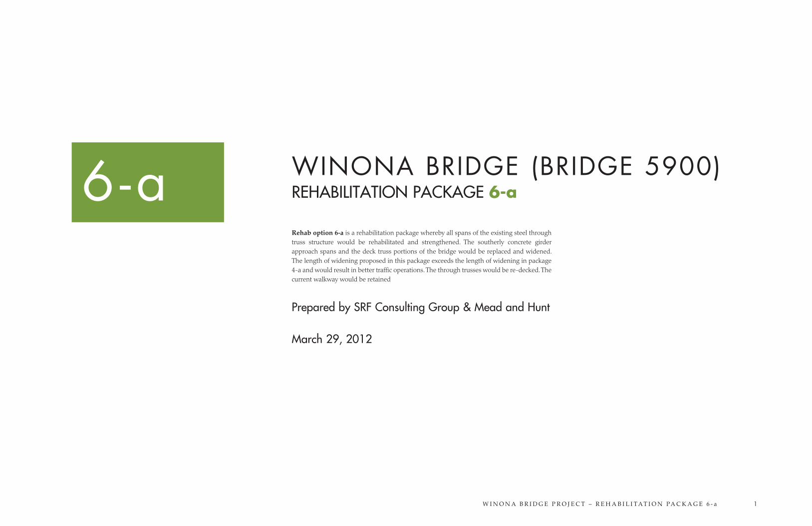
Figure 1. Existing Winona Bridge (Bridge 5900), looking north from Winona onto Latsch Island and into Wisconsin
W I N O N A B R I D G E P R O J E C T – R E H A B I L I T A T I O N PA C K A G E 6 - a 3
2. Rehabilitation Package DefinitionRehab option 6-a is a rehabilitation package whereby all spans of the existing steel through truss structure would be rehabilitated and strengthened. The southerly concrete girder approach spans and the deck truss portions of the bridge would be replaced and widened. The length of widening proposed in this package exceeds the length of widening in package 4-a and would result in better traffic operations. The through trusses would be re-decked. The current walkway would be retained
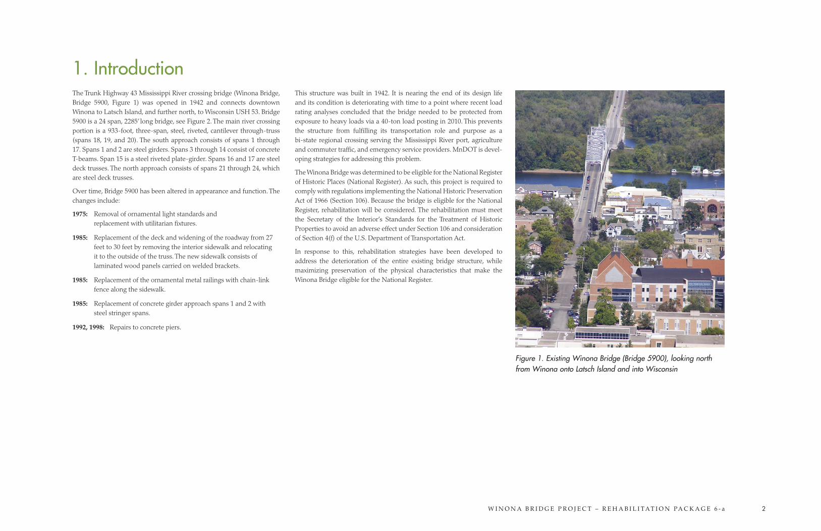
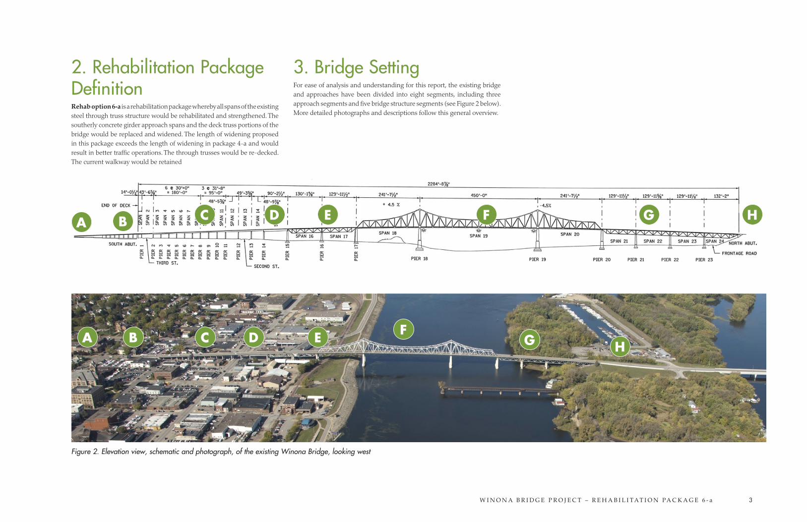
3. Bridge SettingFor ease of analysis and understanding for this report, the existing bridge and approaches have been divided into eight segments, including three approach segments and five bridge structure segments (see Figure 2 below). More detailed photographs and descriptions follow this general overview.
Figure 2. Elevation view, schematic and photograph, of the existing Winona Bridge, looking west
A
A
C
C
B
B
D
D
E
E
F
F
G
G
H
H
W I N O N A B R I D G E P R O J E C T – R E H A B I L I T A T I O N PA C K A G E 6 - a 4
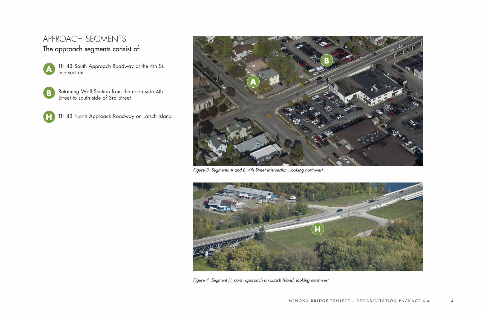
APPROACH SEGMENTS The approach segments consist of:
TH 43 South Approach Roadway at the 4th St. Intersection
Retaining Wall Section from the north side 4th Street to south side of 3rd Street
TH 43 North Approach Roadway on Latsch Island
Figure 3. Segments A and B, 4th Street intersection, looking northwest
Figure 4. Segment H, north approach on Latsch Island, looking northwest
A
B
H
H
A
B
W I N O N A B R I D G E P R O J E C T – R E H A B I L I T A T I O N PA C K A G E 6 - a 5
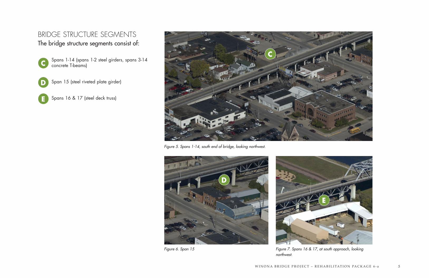
BRIDGE STRUCTURE SEGMENTS The bridge structure segments consist of:
Spans 1-14 (spans 1-2 steel girders, spans 3-14 concrete T-beams)
Span 15 (steel riveted plate girder)
Spans 16 & 17 (steel deck truss)
Figure 5. Spans 1-14, south end of bridge, looking northwest.
Figure 6. Span 15 Figure 7. Spans 16 & 17, at south approach, looking northwest.
CC
D
D
E
E
W I N O N A B R I D G E P R O J E C T – R E H A B I L I T A T I O N PA C K A G E 6 - a 6
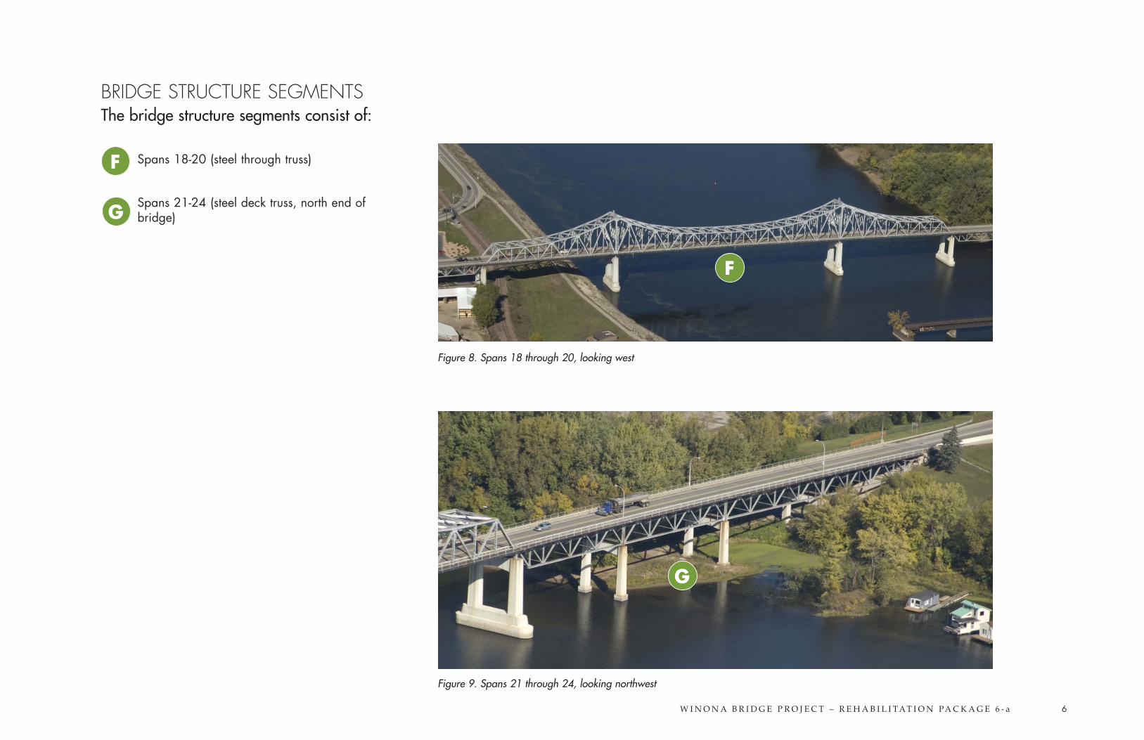
Figure 8. Spans 18 through 20, looking west
Figure 9. Spans 21 through 24, looking northwest
F
G
BRIDGE STRUCTURE SEGMENTS The bridge structure segments consist of:
Spans 18-20 (steel through truss)
Spans 21-24 (steel deck truss, north end of bridge)
F
G
W I N O N A B R I D G E P R O J E C T – R E H A B I L I T A T I O N PA C K A G E 6 - a 7
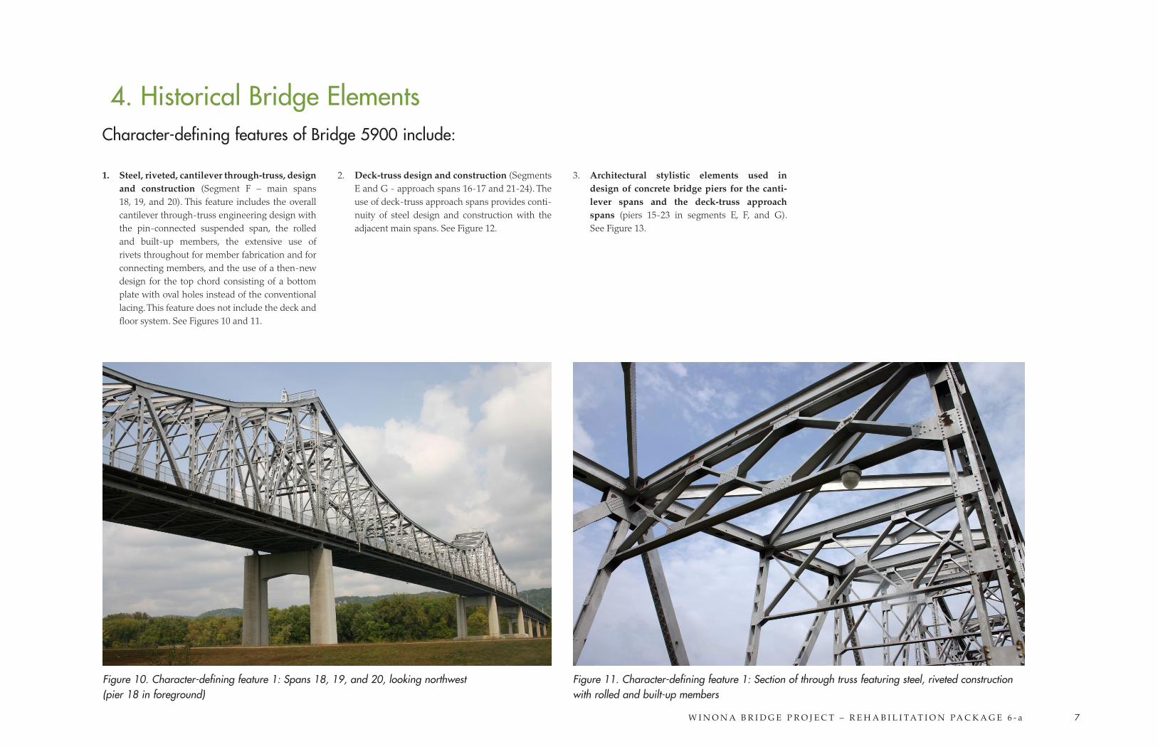
1. Steel, riveted, cantilever through-truss, design and construction (Segment F – main spans 18, 19, and 20). This feature includes the overall cantilever through-truss engineering design with the pin-connected suspended span, the rolled and built-up members, the extensive use of rivets throughout for member fabrication and for connecting members, and the use of a then-new design for the top chord consisting of a bottom plate with oval holes instead of the conventional lacing. This feature does not include the deck and floor system. See Figures 10 and 11.
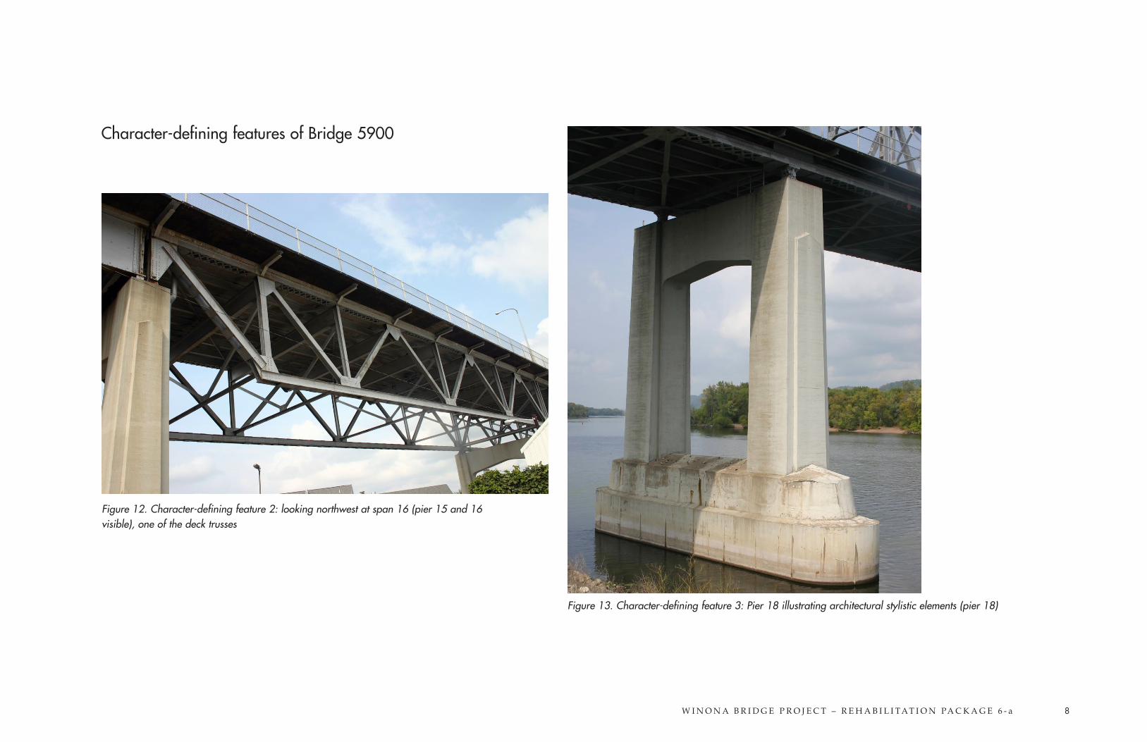
2. Deck-truss design and construction (Segments E and G - approach spans 16-17 and 21-24). The use of deck-truss approach spans provides conti-nuity of steel design and construction with the adjacent main spans. See Figure 12.
3. Architectural stylistic elements used in design of concrete bridge piers for the canti-lever spans and the deck-truss approach spans (piers 15-23 in segments E, F, and G). See Figure 13.
4. Historical Bridge Elements
Figure 10. Character-defining feature 1: Spans 18, 19, and 20, looking northwest (pier 18 in foreground)
Figure 11. Character-defining feature 1: Section of through truss featuring steel, riveted construction with rolled and built-up members
Character-defining features of Bridge 5900 include:
W I N O N A B R I D G E P R O J E C T – R E H A B I L I T A T I O N PA C K A G E 6 - a 8
Character-defining features of Bridge 5900
Figure 12. Character-defining feature 2: looking northwest at span 16 (pier 15 and 16 visible), one of the deck trusses
Figure 13. Character-defining feature 3: Pier 18 illustrating architectural stylistic elements (pier 18)
W I N O N A B R I D G E P R O J E C T – R E H A B I L I T A T I O N PA C K A G E 6 - a 9
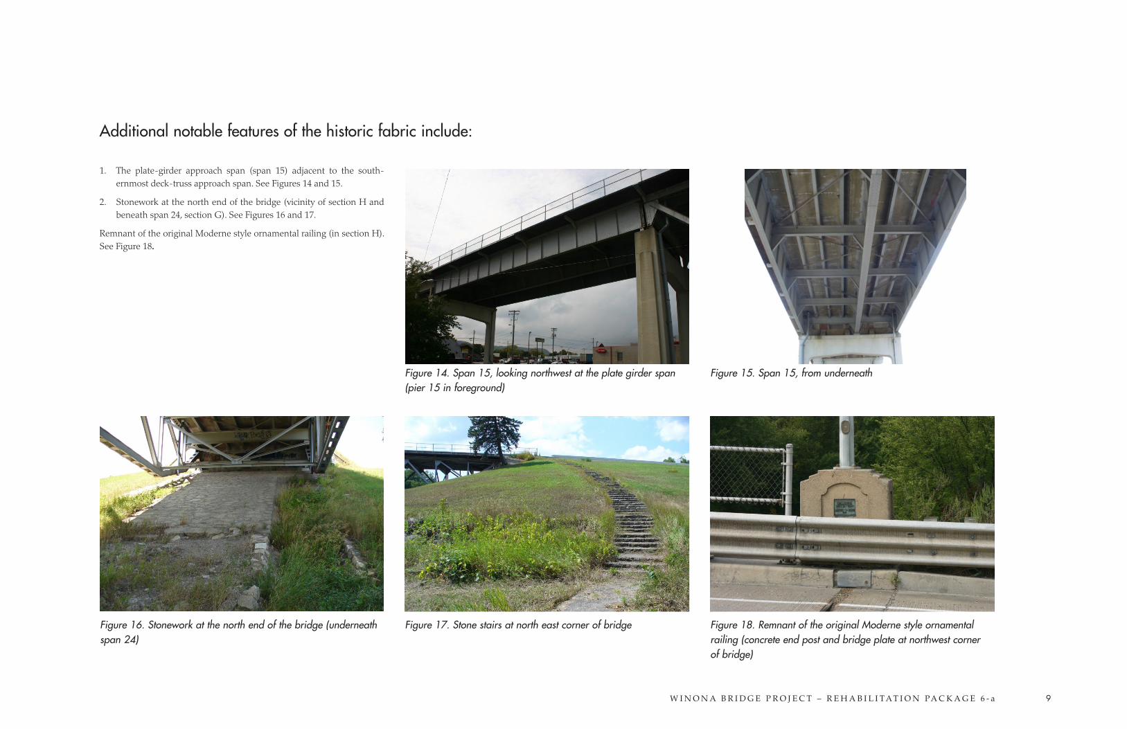
1. The plate-girder approach span (span 15) adjacent to the south-ernmost deck-truss approach span. See Figures 14 and 15.
2. Stonework at the north end of the bridge (vicinity of section H and beneath span 24, section G). See Figures 16 and 17.
Remnant of the original Moderne style ornamental railing (in section H). See Figure 18.
Figure 16. Stonework at the north end of the bridge (underneath span 24)
Figure 18. Remnant of the original Moderne style ornamental railing (concrete end post and bridge plate at northwest corner of bridge)
Figure 15. Span 15, from underneath
Figure 17. Stone stairs at north east corner of bridge
Figure 14. Span 15, looking northwest at the plate girder span (pier 15 in foreground)
Additional notable features of the historic fabric include:
W I N O N A B R I D G E P R O J E C T – R E H A B I L I T A T I O N PA C K A G E 6 - a 10
Continuous across bridge (all segments)• Remove and replace concrete deck
• Retain existing sidewalk
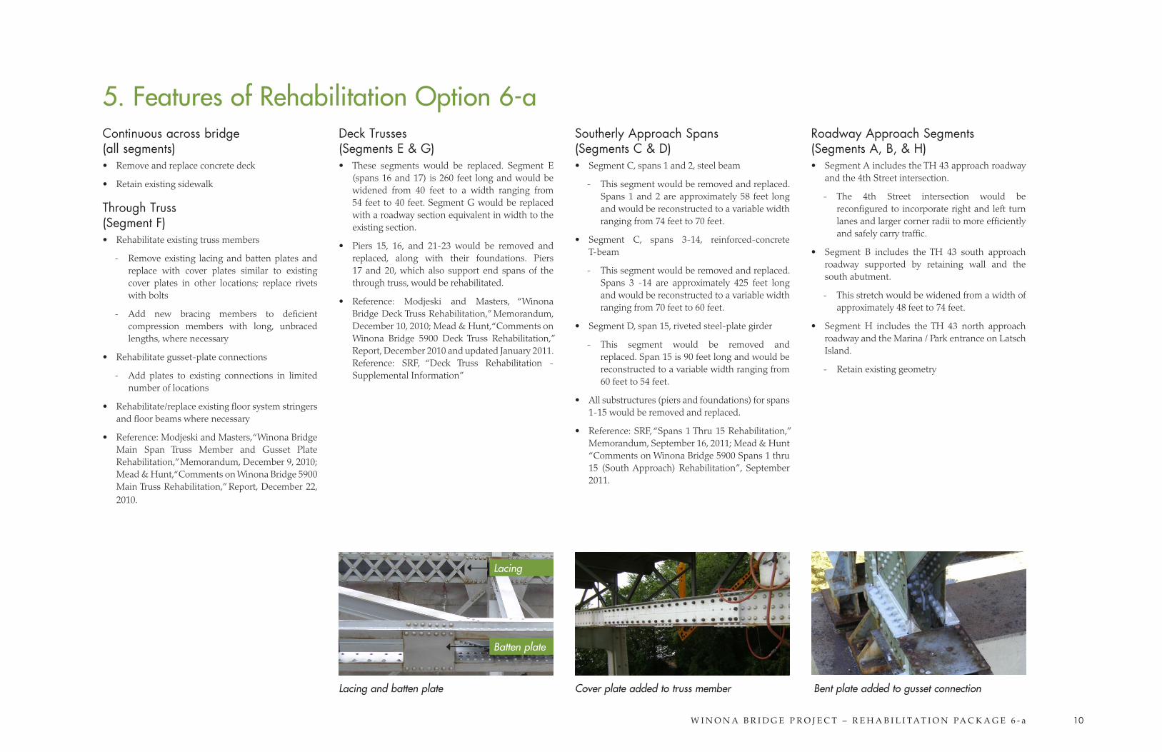
Through Truss (Segment F)• Rehabilitate existing truss members
- Remove existing lacing and batten plates and replace with cover plates similar to existing cover plates in other locations; replace rivets with bolts
- Add new bracing members to deficient compression members with long, unbraced lengths, where necessary
• Rehabilitate gusset-plate connections
- Add plates to existing connections in limited number of locations
• Rehabilitate/replace existing floor system stringers and floor beams where necessary
• Reference: Modjeski and Masters, “Winona Bridge Main Span Truss Member and Gusset Plate Rehabilitation,” Memorandum, December 9, 2010; Mead & Hunt, “Comments on Winona Bridge 5900 Main Truss Rehabilitation,” Report, December 22, 2010.
Deck Trusses (Segments E & G)• These segments would be replaced. Segment E
(spans 16 and 17) is 260 feet long and would be widened from 40 feet to a width ranging from 54 feet to 40 feet. Segment G would be replaced with a roadway section equivalent in width to the existing section.
• Piers 15, 16, and 21-23 would be removed and replaced, along with their foundations. Piers 17 and 20, which also support end spans of the through truss, would be rehabilitated.
• Reference: Modjeski and Masters, “Winona Bridge Deck Truss Rehabilitation,” Memorandum, December 10, 2010; Mead & Hunt, “Comments on Winona Bridge 5900 Deck Truss Rehabilitation,” Report, December 2010 and updated January 2011. Reference: SRF, “Deck Truss Rehabilitation - Supplemental Information”
Southerly Approach Spans (Segments C & D)• Segment C, spans 1 and 2, steel beam
- This segment would be removed and replaced. Spans 1 and 2 are approximately 58 feet long and would be reconstructed to a variable width ranging from 74 feet to 70 feet.
• Segment C, spans 3-14, reinforced-concrete T-beam
- This segment would be removed and replaced. Spans 3 -14 are approximately 425 feet long and would be reconstructed to a variable width ranging from 70 feet to 60 feet.
• Segment D, span 15, riveted steel-plate girder
- This segment would be removed and replaced. Span 15 is 90 feet long and would be reconstructed to a variable width ranging from 60 feet to 54 feet.
• All substructures (piers and foundations) for spans 1-15 would be removed and replaced.
• Reference: SRF, “Spans 1 Thru 15 Rehabilitation,” Memorandum, September 16, 2011; Mead & Hunt “Comments on Winona Bridge 5900 Spans 1 thru 15 (South Approach) Rehabilitation”, September 2011.
Roadway Approach Segments (Segments A, B, & H)• Segment A includes the TH 43 approach roadway
and the 4th Street intersection.
- The 4th Street intersection would be reconfigured to incorporate right and left turn lanes and larger corner radii to more efficiently and safely carry traffic.
• Segment B includes the TH 43 south approach roadway supported by retaining wall and the south abutment.
- This stretch would be widened from a width of approximately 48 feet to 74 feet.
• Segment H includes the TH 43 north approach roadway and the Marina / Park entrance on Latsch Island.
- Retain existing geometry
5. Features of Rehabilitation Option 6-a
Lacing and batten plate Cover plate added to truss member Bent plate added to gusset connection
Lacing
Batten plate
W I N O N A B R I D G E P R O J E C T – R E H A B I L I T A T I O N PA C K A G E 6 - a 11
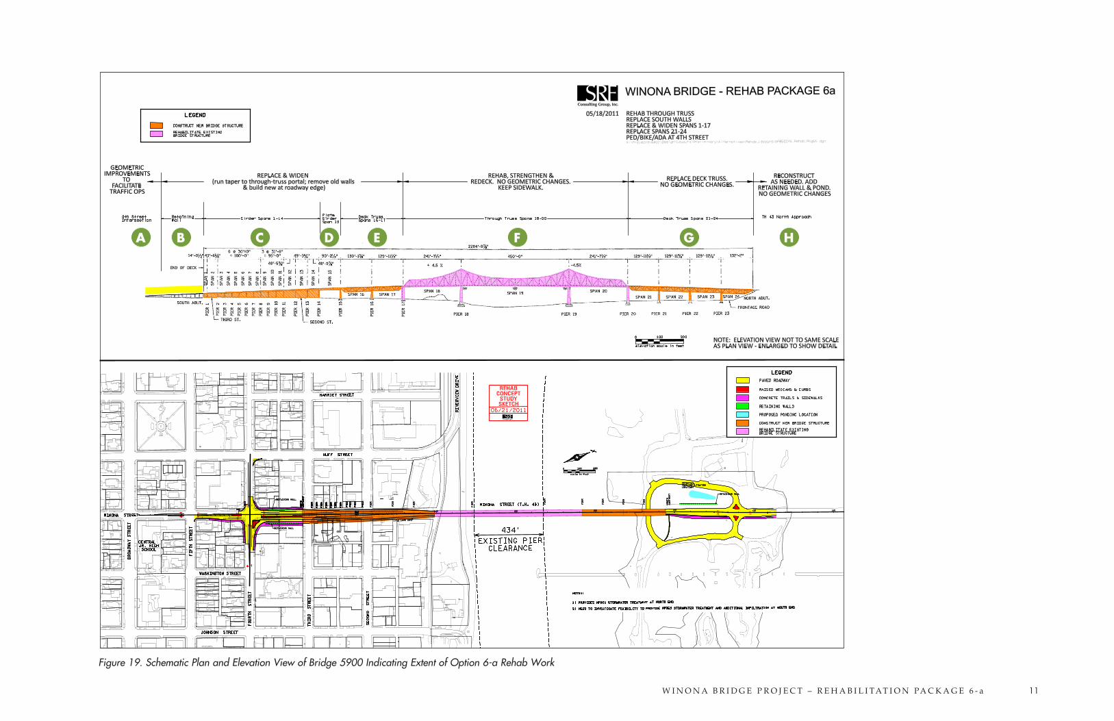
Figure 19. Schematic Plan and Elevation View of Bridge 5900 Indicating Extent of Option 6-a Rehab Work
A CB D E F G H
W I N O N A B R I D G E P R O J E C T – R E H A B I L I T A T I O N PA C K A G E 6 - a 12
6. Issues and AnalysisAbility to meet the project’s purpose and need.• The Purpose and Need statement formally defines
why Mn/DOT is doing the project and states the problems to be addressed. There are three tiers within the overall Purpose and Need:
1. Primary Need – the primary need / objective for the project. For this project the primary need is to provide a structurally sound, safe crossing of the Mississippi River at Winona. The primary need is indicated by the designation “(1)” in the discussion below.
2. Secondary Needs – To be given strong consideration in the development and evaluation of alternatives. Several secondary needs have been identified for this project. Secondary needs are indicated by the designation “(2)” in the discussion below.
3. Other Considerations – To be considered in the development and evaluation of alternatives, but with less importance than the Secondary Needs. Other considerations are indicated by the designation “(3)” in the discussion below.
• Rehabilitation treatments proposed for Bridge 5900 under Option 6-a would address the following elements of the project’s purpose and need:
- Provide a structurally sound, safe crossing of Mississippi River at Winona (1)
- Connect to Wisconsin highway system (2)
- Maintain access to Latsch Island (2)
- Minimize truck routing impacts to residential areas (3)
- Provide structural redundancy (Approach spans – Segments B & C) (3)
- Provide structural redundancy (deck truss spans – Segments E & G) (3)
- Opportunities to improve traffic safety and capacity – by widening the southerly bridge approach area, e.g. the north leg of 4th Street & TH 43. (2)
- Improve geometrics (3)
• Rehabilitation treatments proposed for Bridge 5900 under Option 6-a may address the following elements of the project’s purpose and need (additional detail remains to be developed):
- Maximize “maintenance of traffic” (keeping the crossing and navigation channel open) 2)
- Meet critical regulatory requirements (2)
• Rehabilitation treatments proposed for Bridge 5900 under Option 6-a would not address the following elements of the project’s purpose and need:
- Improve pedestrian / bicycle connections – the existing walk in Segment F would not be widened to meet current standards (3)
- Provide structural redundancy (through truss – Segment F) (3)
Ability to meet the Secretary’s Standards (evaluated by bridge spans/segments).• Rehabilitation treatments proposed for the through
truss (Segment F) comply with the Secretary’s Standards and would result in no adverse effect.
• Removal of deck truss (Segments E & G) would not comply with the Secretary’s Standards and would result in an adverse effect.
• Removal of deck truss would also remove the piers and would result in an adverse effect.
• Removal of the south approach spans 1-15 (Segments C&D) would not comply with the Secretary’s Standards and would result in an adverse effect.
Traffic operations and safety at 4th Street.• The existing approach roadways would be widened
to accommodate large truck traffic more efficiently.
• As a result of proposed widening, traffic operations at the Winona Street intersection projected for 2038 would be an acceptable LOS D.
• The widening would be approximately 200 feet longer than in option 4-a. This extra length would allow traffic to operate at a stable flow condition, whereas the shorter additional lane in option 4-a would not allow merging traffic to accelerate sufficiently to merge into the through lane at similar speeds. The option 4-a condition would trigger queues and cause operations to be unstable.
Temporary maintenance of traffic (MOT)/ROW impacts. • Performing the rehab project under traffic would
be very difficult and would add significant time to the construction schedule. Some phases of rehab work cannot be performed under traffic and would require temporary closure of the bridge.
• Long-term traffic closure of the bridge and rerouting of traffic via a detour or temporary bridge would allow the most efficient rehab project because segments of the bridge can be removed.
• Accelerated bridge construction techniques will be considered.
Pedestrian and bicycle accommodations. • This rehab option would not alter the existing
4-1/2 foot wide cantilevered walkway, which is not historic. The existing walkway width does not meet current ADA requirements or current design standards for bicycle and pedestrian use. However, the existing walkway was constructed before 1990 and would be grandfathered in to meet ADA requirements and could be reconstructed with no geometric changes. An additional sidewalk on the upstream side of the through truss may be considered.
• If a new, wider walkway were to be added, major reconstruction of the entire structure beyond the rehab treatments in this option would be required to meet current design standards.
• If the existing non-historic walkway were to be permanently removed, less rehab work may be required on the truss spans. However, unless an
alternate bike/ped crossing is provided, removal of the existing walkway would not meet the need of providing pedestrian access to Latsch Island.
Risk• Since the deck truss spans would be replaced under
this option, risk associated with rehabilitation of intricate elements and connections of the steel deck truss spans is eliminated. From an engineering perspective, it is not deemed necessary to remove the through trusses because they are generally in better condition.