Embed Size (px)
Citation preview

CIVIL ENGINEERING PRACTICE 2013 1
MATTHEW A. TAYLOR & JOHN G. DELANO
The Massachusetts Department of Con -ser vation and Recreation (DCR) ownsand operates the Otis Reservoir Dam in
Otis, Massachusetts, for recreational purposes.In 2006, the 145-year-old, 31.5-foot-tall, earth-en embankment dam with downstreammasonry wall and stone masonry spillway
was found to be in “Poor” condition due pri-marily to the deteriorating/leaking spillwayand downstream masonry wall and the erodi-bility of the “emergency spillway” over themain embankment section of the dam.
To address most of the main dam safetyconcerns, a reconstructed spillway with ahydraulically actuated crest gate was chosenas the preferred alternative. The crest gateoption provided additional hydraulic capacitywhile also improving the DCR’s ability tomanage the reservoir level, most importantly,during the annual winter drawdown.
During the planning stages of the project,maintaining access to the west side of thereservoir during construction was identifiedas a critical component in the viability of theproject. At the time, the bridge over the spill-way was a one and one-half lane, temporary
Project Considerations
Rehabilitation of theOtis Reservoir Dam:Improving CostEffectiveness byIncluding BridgePlacement
Combining efforts to addressdam safety issues with accessand transportation issues provided a win-win situationfor all of the involved parties.
CEP_28_Taylor_Layout 1 2/13/2014 4:02 PM Page 1

“Bailey bridge” installed in 1995. It was sup-posed to have been replaced with a permanentbridge in 1998. Given that the dam is a large,high hazard structure, the dam repairs neededto move forward to protect the public safety.To expedite the project, the DCR elected toincorporate the bridge replacement into thedam rehabilitation project. The dam rehabili-tation project was transformed, by necessityand creative planning, into a combined damand bridge replacement project that ultimate-ly benefited the DCR and the town of Otis.
Project Background Otis Reservoir Dam is located within TollandState Forest on the Fall River in the town ofOtis, in Berkshire County (see Figure 1). Thedam was originally constructed in 1866 by theFarmington River Water Power Company inorder to provide supplemental water to powermills on the Farmington River in Connecticut.The Commonwealth acquired the reservoir in1967. Otis Reservoir is a 1,000-acre impound-ment with a 16-square-mile drainage area thatencompasses portions of three towns (Otis,Tolland and Blandford). Having a storagecapacity of 22,000 acre-feet (7.1 billion gallons)at normal pool, it is the largest recreationalbody of water in the Commonwealth of Mas -sa chusetts.
Tolland Road, owned by the town of Otis,passes over the dam and provides the onlyaccess to the western side of the reservoir dur-ing the winter months. The majority of the res-idents on the western side of the impound-ment are seasonal, with only four full-timeresidents present during the winter. Becauseof the recreation industry supported by thereservoir, the population in the town of Otisswells from a few thousand in the winter tonear 10,000 during the summer months.
The Otis Reservoir Dam consists of anearthen embankment with a downstreamstone masonry wall. The dam has a maximumstructural height of about 31.5 feet and alength of about 630 feet. The exposed portionof the downstream masonry wall of the dam isapproximately 480 feet in length. TollandRoad, a paved public roadway, traverses thetop of the dam. In 1955/1956, after HurricaneDiane, the top of the embankment was low-
ered by about 3 feet to create an “emergencyspillway,” although no erosion protection,other than the asphalt pavement roadway,was provided. The dam was originally builtwith a 38-foot-long stone masonry primaryspillway located near the dam’s left (west)abutment. The spillway was divided into two,19-foot-long segments by a stone masonrypier.
In 1995, MassHighway replaced the deteri-orating original bridge over the spillway witha temporary one and one-half lane Baileybridge. This bridge was intended to be in serv-ice for three years. A permanent, two-lanebridge was slated for construction in 1998.However, the project was delayed and post-poned, apparently due to MassHighway’sbridge project prioritizations. By 2009, the per-manent bridge replacement at the OtisReservoir Dam had been officially postponeduntil 2014.
Prior to the recent dam rehabilitation, therewere two gatehouses/outlet structures at thedam. The original gatehouse, located in themiddle of the upstream side of the embank-ment, was taken out of service in 1984 whenthe outlet works at the dam were rehabilitat-ed. The original sluice gates, stems and opera-tors were removed and a 4-foot-high by 8-foot-wide intake conduit, with an upstreamsteel trash rack, was installed within the reser-voir. The intake conduit extends into the reser-voir about 40 feet upstream of the dam. Adownstream outlet tower was constructed in1984 with a second gatehouse opposite to theoriginal upstream gatehouse. The outlet towerhas two, 48-inch-square slide gates. One gateserves as a low-level outlet and the otherserves as a mid-level outlet. The outlet toweralso has a 10-foot-wide by 3-foot-high over-flow weir at the same elevation as the primaryspillway crest (with the flashboard in place).The two original 30-inch-square stone sluice-ways through the dam had been retrofittedwith 26-inch-square steel conduits and thengrouted in place.
The Otis Reservoir is operated by theDCR’s park staff according to an order ofconditions from the Otis ConservationCommission, which defines the target sea-sonal reservoir levels and governs the rates
2 CIVIL ENGINEERING PRACTICE 2013
CEP_28_Taylor_Layout 1 2/13/2014 4:02 PM Page 2

of reservoir drawdown and refill. In Octoberof every year, the DCR opens the low-leveloutlet gate to provide a flow of around 300cubic feet per second (cfs) into the Fall River
for an annual weekend canoe race. The DCRsubsequently dials back the release to lowerthe reservoir to about 2 inches per day untilthe winter pool elevation (6 to 8 feet below
CIVIL ENGINEERING PRACTICE 2013 3
FIGURE 1. The location of the Otis Reservoir and dam.
CEP_28_Taylor_Layout 1 2/13/2014 4:02 PM Page 3

4 CIVIL ENGINEERING PRACTICE 2013
the primary spillway crest elevation) isreached. The purpose of the annual draw-down is to allow for the inspection of thedam structure, to prevent ice damage to theshoreline docks and piers, and to providemeltwater storage and discharge controlduring the spring freshet. Beginning inJanuary of each year, the DCR begins to raisethe reservoir level. The reservoir is raised towithin 4 feet of the summer pool level byApril, depending on the ice conditions onthe reservoir. The goal is to have the reser-voir level restored to the summer pool levelby July 4th each year. The 1984 outlet worksconfiguration requires constant adjustmentto manage the reservoir level, especiallyprior to or after storm events.
With the winter pool being maintained byreleasing water from the low-level outlet inthe downstream outlet tower, the DCR couldnot easily monitor the water level below the
ice. An excessive water release could cause thedevelopment of a void between the bottom ofthe ice and the surface of the reservoir. Thepresence of such a void would be a major safe-ty concern, given the year-round recreationaluse of the reservoir, which includes ice fishingand snowmobiling on the reservoir. TheDCR’s staff would use a chain saw to cut holesthrough the ice in order to evaluate the reser-voir level. Obviously, this practice was not anideal approach. So, the DCR indicated that thedam rehabilitation project should also includeprovisions to improve the reservoir operationprocedures.
Engineering Evaluations &Alternative AnalysesFollowing an inspection of the dam in May2006 by an engineering consulting firm, thedam was judged to be in “poor” condition.The primary deficiencies of the dam were:
FIGURE 2. View of the deteriorated and leaking conditions at the spillway prior to rehabili-tation.
CEP_28_Taylor_Layout 1 2/13/2014 4:02 PM Page 4

• The deteriorated masonry and leakageconditions at the spillway (see Figure 2)and the downstream masonry wall; and,
• The erodibility of the “emergency spill-way” over the main embankment sectionof the dam.
In 2007, the engineering consultant per-formed a Phase II Engineering Evaluation andAlternatives Analysis of the dam. This studyincluded field investigations covering wet-lands delineation, a topographic survey of thedam and nearby areas, rare species determina-tions, diving inspections of the intake conduitand interior of the downstream outlet tower,subsurface explorations with test borings andtaking additional readings from the existinginstrumentation (piezometers and inclinome-ters) at the dam. The consultant’s engineeringevaluations included interpretation of the sub-surface conditions from the test borings, geot-echnical laboratory testing (grain size analy-ses) and existing instrumentation readings, aswell as conducting engineering analysesincluding detailed hydrologic and hydraulicanalyses, liquefaction and seismically inducedsettlement analyses, seepage analyses, slopestability analyses and gravity wall stabilityanalyses.
With Otis Reservoir Dam categorized as alarge, high hazard dam per the Massa chu -setts Dam Safety Regulations, its spillwaydesign flood (SDF) is one-half of the proba-ble maximum flood (½ PMF). The results ofthe detailed hydrologic and hydraulic analy-ses revealed that the original spillway wascapable of passing only 10 percent of the SDFand overtopping of the dam by about 3.3 feetwas predicted. The seepage and stabilityanalyses indicated that the dam met most ofthe stability requirements set forth in thedam safety regulations except for the casewhere the dam was overtopped during theSDF event. The factor of safety against slid-ing for the downstream masonry wall wasbelow the recommended minimum value of1.3 due to the likelihood for erosion occur-ring at the base of the wall attributed to over-topping during the SDF.
In concert with the detailed engineeringanalyses, a potential failure mode analysis
(PFMA) was performed with several membersof consultant’s dam engineering team andrepresentatives from the DCR who wereresponsible for the operation and maintenanceof the dam. The objective of the PFMA was toassess possible failure modes and to deter-mine the most likely failure mechanisms,thereby allowing the design of the rehabilita-tion project to address each of these deficien-cies.
Using the information obtained from thedetailed engineering evaluations and thePFMA, an alternatives analysis was per-formed to evaluate the repair/rehabilitationoptions that could address the dam safetyissues. These alternatives included:
• no action;• breach/remove;• raise the dam;• construct an emergency spillway; and,• spillway modification/reconstruction.
Spillway reconstruction, along with raisingthe crest of the dam, were selected as the pre-ferred alternatives.
Selection of the Preferred AlternativesTo address both the dam safety issues andoperational issues, reconstructing the spillwaywith a bottom-hinged, 7.5-foot-tall by 38-foot-wide steel crest gate was selected as a pre-ferred alternative. When the crest gate is in the“up” or “closed” position, the top of the gateis at the current normal summer pool eleva-tion for the reservoir. The invert of the newspillway (i.e., with the crest gate in the“down” or “open” position) was set at thewinter pool elevation so that once the reser-voir was drawn down it could “self-regulate”the reservoir level without constant assess-ment and adjustment by the DCR staff.
To safely pass the SDF, the DCR staffwould need to lower the summer reservoirlevel by 2 feet in advance of the ½ PMFevent and then operate the gate throughoutthe storm to prevent overtopping of thedam. Without proper gate operation, thedam will be subject to overtopping duringthe SDF. However, the proposed dam modi-
CIVIL ENGINEERING PRACTICE 2013 5
CEP_28_Taylor_Layout 1 2/13/2014 4:02 PM Page 5

fications would allow the spillway to safelypass the 500-year flood event with about 2feet of freeboard without lowering the crestgate.
Typically, relying on human operations topass the SDF is not a recommended dam safe-ty practice. The reason it is not recommendedis the potential for improper or lack of opera-tion that can result from human error. How -ever, Otis Reservoir Dam is not a typical damsince it has a full-time dam operations staff inthe DCR’s Tolland State Forest Office at theright abutment of the dam. The DCR also hasstaff who live locally who are “on-call” shouldan emergency situation develop at the dam.Therefore, the design of the new spillway wasable to take advantage of the DCR’s somewhatunique on-site staffing situation.
Other improvements included in the damrehabilitation, as shown in Figure 3, were:
• adding a new gatehouse on the leftabutment of the dam;
• raising the top of the dam by adding upto 3 feet of embankment fill;
• repointing the downstream masonrywall;
• extending the downstream toe drain;• adding a reinforced concrete splash pad
at the base of the downstream masonrywall;
• restoring the rip-rap slope protection onthe upstream and portions of thedownstream slopes; and.
• installing new slide gates on the insideupstream face of the downstream outlettower.
Solving Resident Access IssuesAccess to the west side (left side of the dam) ofthe reservoir was identified as a critical issueearly in the project development. The towns ofOtis and Tolland fully understood the benefitof the project. However, residents of bothtowns were concerned about the potential forshort-term impacts on the recreational-based
6 CIVIL ENGINEERING PRACTICE 2013
FIGURE 3. The locations of repairs/improvements on the dam.
Reconstruct spillway & bridge
Construct spillwaycontrol building
Demolish unusedupstream building
Rehabilitateupstream slope
Repair downstream masonry &construct new toe drain
Rehabilitate outlet tower controls
Raise top of dam, improve roadwayalignment & pedestrian access
N
CEP_28_Taylor_Layout 1 2/13/2014 4:02 PM Page 6

economy. Several concepts and options wereevaluated by the project team in order toaddress this concern.
Initially, a bypass route upstream of thespillway was evaluated. A temporary earthenembankment was considered that would con-vey traffic around the spillway constructionwhile also serving as a temporary cofferdamfor the work area. A significant amount of fillwould have been needed to be placed in wet-lands area fro the embankment. This optionwas eliminated when the constructability, costand permitting requirements were evaluatedmore closely.
A second approach that was consideredwas to construct the spillway in two segments:upstream and downstream. The existingBailey bridge would be left in place initially toallow the upstream portion of the spillway tobe constructed. The Bailey bridge would thenbe moved to the upstream side of the dam andthe downstream half of the spillway would beconstructed. However, this option was alsoeliminated when the costs associated with thephased construction, the extended construc-tion duration, the need for a more robust tem-porary cofferdam capable of remaining inplace throughout the higher summer pool sea-son and the additional risks were evaluatedmore closely.
To limit the impact of the project on therecreational use of the reservoir, it was decid-ed that the majority of the work needed to beperformed in off-season (i.e., winter construc-tion). It was also obvious that with the signifi-cant improvements being considered for thespillway, it did not make sense to reinstall thetemporary Bailey bridge over the newlyreconstructed spillway. Therefore, the DCRdecided to incorporate a permanent bridgereplacement into the dam rehabilitation proj-ect. In exchange for adding the new bridge tothe project, the DCR was granted permissionfrom the towns of Otis and Tolland to closeTolland Road for five months (from October2010 to March 2011) in order to facilitate con-struction.
To address the access issue to the west sideof the reservoir, the DCR offered to establishand maintain a detour route around the reser-voir during the five-month period when the
bridge was closed. The detour route (seeFigure 4), which was about 8 miles in length,included a 2.8-mile section of gravel road thatwas typically not plowed during the winter.The DCR included a construction contractprovision for liquidated damages to be leviedagainst the contractor if the bridge over thespillway was not reopened on time. The townof Otis accepted the DCR’s offer for the newbridge and the temporary detour route, andgranted the DCR permission to close TollandRoad for five months.
Dam & Bridge DesignConsiderationsThe design of the dam rehabilitation and thebridge replacement occurred between 2007and 2010. The engineering consultant retainedanother engineering firm to provide structur-al, mechanical and electrical engineeringdesign services for the new crest gate and fortwo new slide gates in the outlet tower.Under a separate contract, the MassachusttsDepartment of Transportation (MassDOT)engaged another consultant to perform thebridge design. The DCR supervised the bridgedesigner and reported progress to MassDOT.As overall project manager and the dam engi-neer-of-record, the contracting engineeringconsultant was responsible for providingengineering design for the dam, including thehydrologic/hydraulic, geotechnical and civildesigns, in addition to coordinating the otherproject team design responsibilities and merg-ing of the contract documents into a single bidpackage.
A performance-based specification was cre-ated for the crest gate. Two Massachusetts-based gate manufacturers were consulted toprovide input in establishing the crest gatedesign criteria and to understand the implica-tions of the DCR’s intended operation proce-dures. The DCR was committed to providingredundancy with the crest gate operations.The DCR wanted the gate to have twin top-mounted actuators, but the DCR also wantedto have the ability to operate the gate with asingle actuator in the event that one failed.Based on this requirement, a hydraulicallyactuated operation system was selected for theproject. Velocity fuses (i.e., a hydraulic valve
CIVIL ENGINEERING PRACTICE 2013 7
CEP_28_Taylor_Layout 1 2/13/2014 4:02 PM Page 7

used to stop flow if the maximum speed of thefluid is exceeded) were also added to the sys-tem to prevent the gate from opening uninten-tionally in the event of a power loss or a breakin the hydraulic system. The gate system also
included provisions to raise or lower the gatemanually in an emergency situation. A newgatehouse was also added on the left (west)abutment of the dam to house the crest gate’shydraulic system.
8 CIVIL ENGINEERING PRACTICE 2013
FIGURE 4. The 8-mile detour route that was used during construction.
Dam Site
CEP_28_Taylor_Layout 1 2/13/2014 4:02 PM Page 8

With the reservoir’s annual drawdownschedule, there is a need to operate the gate incold-weather months. However, the rubberside and invert seals could be damaged if thecrest gate is operated while it is subjected toice accumulation. As such, robust electric sideseal and invert heaters were incorporated intothe structure. Operational procedures to turnon the heaters in advance of any winter gateoperations were also written into the dam’snew operations and maintenance plan. Thenew gatehouse constructed near the spillwayto house the crest gate controls included pro-visions for connecting a portable generator ifspillway operations were required duringpower outages.
The existing masonry spillway wasremoved and replaced with a reinforced con-crete structure to support the crest gate and toconvey the spillway flow through the dam.The new spillway structure served dual pur-poses: spillway training wall and bridge abut-ments. (In addition to the hydraulic loadsimparted due to the spillway flows, the newconcrete walls were also required to supportthe lateral loads from the embankment, verti-cal dead forces from the bridge structure andHS-25 vehicle loading, and earthquake loads.)The training walls/abutments were to befounded directly on bedrock, which providedadequate bearing capacity and erosion resist-ance.
Several types of superstructure for the newbridge were considered in the early part of theproject. Initially, the bridge types consideredincluded:
• Single span, precast, prestressed concretespread box beams with cast-in-placeconcrete deck.
• Single span, rolled steel stringers with acast-in-place deck.
• Single span, built-up steel plate girderswith a cast-in-place deck.
• Single span, rolled steel stringers with atimber deck.
The initial recommendation for a bridgetype was for a single span, precast concretespread box beams with a cast-in-place deck.However, the winter construction schedule
and the necessity for limited road closure pre-cluded any of the bridge types that used cast-in-place decks. Therefore, a decision wasmade by the project team to only considerbridge types that used prefabricated elements,since they could be brought on-site and low-ered into place once the spillway trainingwalls/bridge abutments were completed. Theprefabricated bridge types that wereconsidered included:
• Prefabricated concrete/steel compositesuperstructure units (formally known asInverset);
• NEXT beam system;• Fiber reinforced polymer (FRP) deck on
steel stringers;• Full depth precast concrete deck panels
on concrete or steel stringers; and,• Butted boxes/deck slab with no cast-in-
place deck.
The effects of each system on thehydraulic performance of the spillway, theirrelative maintenance costs and their impacton construction schedule (if any) were eval-uated. The first alternative — prefabricatedconcrete/steel composite superstructureunits with an asphalt wearing course — waschosen. The composite system includedsteel stringers and a precast concrete deck.The main benefits of this bridge type includ-ed design flexibility, adaptability to thewinter construction schedule and quickinstallation.
Improving Constructability byModifying the Spillway DesignThe winter-only construction schedule, cou-pled with the five-month road closure limita-tion, dictated that the total construction sched-ule for the project occur over a two-year peri-od. And, with the crest gate design, submittalreview process and fabrication requiring up tosix to eight months, the crest gate installationwas not scheduled until the second winterconstruction season. This schedule wouldhave not been possible if the project had beenawarded in the fall since the spillway con-struction would have needed to have beencompleted during the winter road closure of
CIVIL ENGINEERING PRACTICE 2013 9
CEP_28_Taylor_Layout 1 2/13/2014 4:02 PM Page 9

the first construction season. In order toaccommodate this scheduling issue, the deci-sion was made to add stop logs bays to thespillway upstream of the proposed crest gate.The addition of the upstream stop logs pro-vided the following benefits:
• The stop logs provide a permanent mech-anism to allow the crest gate to be takenoff line for servicing and maintenance.
• The stop logs could be installed early inthe spillway construction in order to limitthe amount of time needed for a tempo-rary cofferdam for the project.
• The stop logs could be installed and keptin place to serve as the water controlmechanism until the crest gate was fullyinstalled. Doing so would allow the crestgate design, submittal review and fabri-cation to proceed without the added pres-sure of being the critical path element forthe project.
• The stop logs would also be used to cre-ate a controlled upstream water condi-tion that would allow testing of the crestgate and the training of the DCR opera-tions staff.
Combined Dam & Bridge DesignBenefits Project FinancingWith the project design and constructabilityissues resolved, the next step was to figure outhow the project would be funded. The initialconstruction cost estimate was on the order of$2 million. The DCR Office of Dam Main ten -ance used this figure in their capital planningfor FY2010/2011. However, the initial costestimate did not include a new bridge nor didit consider a two-season construction sched-ule. Consequently, the updated project costestimate was about $1 million higher thanoriginally estimated. In order to address thecost increase, the DCR needed to look at otherfunding options.
10 CIVIL ENGINEERING PRACTICE 2013
FIGURE 5. Improvements to the dam crest and upstream slope.
CEP_28_Taylor_Layout 1 2/13/2014 4:02 PM Page 10

Because this “dam” now included a newbridge, it became obvious that it should quali-fy for “bridge monies.” The bridge and por-tions of the spillway construction that serveda dual capacity (both spillway training wallsand bridge abutments) were funded via theMassDOT Accelerated Bridge Program andnot solely through the DCR’s Office of DamMaintenance dam rehabilitation budget.Second, by extending the project to two con-struction seasons, the project was also extend-ed over two fiscal years. Consequently, theDCR was able to spread the project budget outover two years, which provided the DCR withgreater fiscal flexibility when compared to theinitial approach when the dam rehabilitationwas scheduled to occur over one constructionseason.
Even though the project scope and budgetwere increased by the addition of the bridgereplacement to the project, the DCR, thetown of Otis and the general public benefit-
ed in a greater way with the expanded proj-ect scope and the DCR’s ability to see the bigpicture.
First-Year Construction HighlightsThe project was advertised for bid in the sum-mer of 2010. The project was awarded to thelow bidder, with a bid price of $3,057,496.50.Seven prequalified contractors submitted bidson the project. The four lowest bidders werewithin $150,000 of each other, and all four ofthese bids came within $300,000 (roughly 10percent) of the engineering consultant’s esti-mate for the project.
On September 15, 2010, the DCR and thecontractor began first construction season.Approximately one month later, the portion ofReservoir Road across the top of the dam wasofficially closed and the detour route aroundthe site was established. The first-yearconstruction work included:
CIVIL ENGINEERING PRACTICE 2013 11
FIGURE 6. Bedrock excavation at the spillway.
CEP_28_Taylor_Layout 1 2/13/2014 4:02 PM Page 11

• the construction of the toe drain andsplash pad;
• raising of the embankment crest by 3 feet;• placement of new upstream and down-
stream riprap slope protection (see Figure5 on page XX);
• demolition of the masonry spillway;• construction of the new reinforced con-
crete spillway/bridge abutments;• installation of the new stop logs;• installation of the new bridge;• demolition of the upstream gatehouse;
and,• construction of the new crest gate gate-
house at the left abutment.
Because the invert of the new crest gateswas almost 8 feet lower than the original spill-way crest, bedrock excavation and removalwithin the spillway footprint was required forfoundation construction. The excavationrequired for the new spillway foundations
was approximately 100 by 80 feet in area, andrequired cuts into the bedrock of up to about 7feet.
Excavation of the gneissic bedrock wasaccomplished with a combination of rippingwith an excavator and hoeramming. Due tothe fracture patterns in the bedrock, con-trolled blasting was not required. Figure 6(on the previous page) shows an example oftypical rock excavation at the spillway.Because the bedrock was fractured and rip-pable, the contractor utilized line drillingtechniques on the outer perimeter of theexcavation area to control the limit of therock removal. Construc tion-induced vibra-tions were limited to the criteria set forth in527 CMR 13.00, which provide vibration lim-its based on a relationship between peak par-ticle velocity and frequency. Continuous andevent-specific vibration monitoring was per-formed for the existing downstream masonryface of the dam, the downstream gate-
12 CIVIL ENGINEERING PRACTICE 2013
FIGURE 7. Concrete work during winter 2010/2011 at the spillway.
CEP_28_Taylor_Layout 1 2/13/2014 4:02 PM Page 12

house/outlet tower, and at locations wherenew concrete was being poured.
The bedrock conditions in the area of thespillway were generally less competent than itwas anticipated during design. Because thetop of competent bedrock was generally about1 to 4 feet deeper than the design bottom offooting grades, approximately 150 additionalcubic yards of concrete were required to reachthe design footing subgrade elevations. Thefinal bedrock surface was cleaned out withcompressed air prior to the placement of theconcrete. At the east bridge abutment, a “shearkey” into the bedrock subgrade was addedbecause of the lower than anticipated compe-tent bedrock surface. This shear key wasadded to increase the passive resistance for thetraining wall/bridge abutment foundation.
December 2010 marked the beginning ofconcrete placement for the new spillway. Italso marked the beginning of one of the cold-est winters in recent years in the Berkshires.
As shown on Figure 7, concrete was formedand poured in heated tents, and was typicallyallowed to cure for at least three days withinthe heated tents prior to stripping forms.Diligent maintenance of the heating system bythe contractor allowed for concrete placementto occur relatively unimpeded despite the coldweather. Rock excavation was not allowed for24 hours after concrete had been poured onthe site, and backfilling was not permitteduntil the concrete had achieved its required28-day compressive strength. Field-curedcylinders were used to determine whetherrequired 28-day compressive strengths wereachieved, which, thus, allowed backfilling tobe performed at an accelerated schedule. Thestop log bays foundations, crest gate founda-tion, as well as upstream and downstreamtraining walls/bridge abutments were allpoured throughout the winter in this mannerwith great success. Side seals and heating ele-ments for the hydraulic crest gate were
CIVIL ENGINEERING PRACTICE 2013 13
FIGURE 8. New spillway bridge installation.
CEP_28_Taylor_Layout 1 2/13/2014 4:02 PM Page 13

installed as part of the training wall construc-tion.
By February 2011, work on the spillwayhad progressed sufficiently to allow backfill-ing between the existing embankment andspillway training/abutment walls. Freezingtemperatures required a diligent effort on thecontractor’s part to provide ground heatersand frost blankets. The specifications for back-fill material were geared toward providingcontrol of seepage through the embankment,as opposed to the free-draining materials com-monly associated with roadway and bridgeconstruction. Because of the relatively highfines content (between 15 and 30 percent) ofthe off-site embankment fill material, moisturecontent significantly impacted the contractor’sability to compact the material to the requireddensity. The backfill material was broughtfrom an off-site borrow pit to the site with amoisture content that was typically well overits optimum moisture content. This condition,
in addition to the rainy/wet weather thatbecame more prevalent in the early spring of2011, caused delays in the backfilling opera-tion. The wet backfill issues were addressedprimarily by providing better control of mois-ture in both the on-site and off-site borrowarea stockpiles. In some instances where mois-ture could not be properly controlled, theamount of fill placed in a single day had to belimited to allow porewater to dissipate priorto the placement of the next lift of fill. Despitethe adverse conditions, the backfilling wascompleted, the stop logs were installed andthe temporary cofferdam was removed in timefor the scheduled bridge/road reopening inMarch 2011.
The new bridge has a 20-foot-wide road-way (curb-to-curb) and a 6-foot-wide side-walk on the north side, resulting in an overallwidth of 29 feet. The bridge can accommodatetwo travel lanes, where the previous “tempo-rary” Bailey bridge could not accommodate
14 CIVIL ENGINEERING PRACTICE 2013
FIGURE 9. Spillway flow due to Tropical Storm Irene.
CEP_28_Taylor_Layout 1 2/13/2014 4:02 PM Page 14

travel in both directions. The wider bridgerequired the location of the new bridge to beshifted southward, with respect to the previ-ous bridge, which resulted in a straighteningof the layout of Tolland Road.
The bridge installation was performedusing a 60-ton crane set up at the east (right)abutment of the spillway (see Figure 8 on pageXX). Com pleting the spillway backfillingoperation was critical since it needed to becompleted ahead of the bridge installation inorder for the bridge and Tolland Road to bereopened to the public by March 2011. Thebridge was fabricated in the three sections,which were trailered individually to the damand staged on the dam crest. The crane wasable to set each bridge section into place in oneday. The grouting of the bridge sections andthe installation of the bridge railings werecompleted over a two-week period and thebridge was opened on schedule on March 18,2011.
A Little More Than Just a “Wet Test”
Between the first and second construction sea-sons, on August 27-28, 2011, Otis Reservoirreceived between about 7 and 10 inches of rainfrom Tropical Storm Irene. In anticipation ofthe storm, the DCR began to lower the reser-voir level with the outlet gate two days priorto the storm’s arrival in the area. The outlettower slide gate was kept open during andafter the storm to help control the reservoirlevel. By the time the storm hit, the DCR hadremoved up to three rows of stop logs (1.5feet). The reservoir level eventually rose toabout 12 inches over normal pool (as seen inFigure 9) on August 29, 2011, which is about 6inches above the maximum reservoir levelused to design the stop logs. On September 1,2011, the DCR reported that the three rows ofstop logs had been replaced and gate in theoutlet tower was closed. The DCR inspected
CIVIL ENGINEERING PRACTICE 2013 15
FIGURE 10. Water flowing over the completed crest gate.
CEP_28_Taylor_Layout 1 2/13/2014 4:02 PM Page 15

the spillway and did not observe any notice-able damage.
Second Year Construction: The Home StretchThe contractor re-mobilized to the site full-time in October 2011 in order to begin con-struction on the last parts of the project. Finalpavement of the road and bridge was placedand the pedestrian railings were completed.Construction of the new gatehouse began con-currently with the installation of the hydrauli-cally actuated crest gate. The new gatehousewas constructed on the left (west) side of thespillway:
• to house equipment and controls associ-ated with the hydraulic crest gate;
• to house the remote water levelinstrumentation system; and,
• to provide secure storage for the alu-minum stop logs.
The crest gate (shown in Figures 10 & 11)was installed by the end of December 2011.The hydraulic system was installed and testedas part of the “dry test” in January 2012. A“wet test” of the crest gate system was alsoperformed shortly thereafter. Although thereservoir was at the winter pool elevation,water could be pumped from the reservoirinto the area between the stop logs and crestgate. So, once again, the inclusion of the stoplogs provided a benefit to the project that wentbeyond their primary objective.
The crest gate system was substantiallycomplete by mid-March 2012 when atraining session was held for the DCRpersonnel who would be operating thenew system.
The new slide gates were installed “in-the-wet” inside the downstream tower on itsupstream face. The new slide gates includednew electric actuators (with manual backup).These new slide gates were installed with new
16 CIVIL ENGINEERING PRACTICE 2013
FIGURE 11. Complete crest gate in in the spillway.
CEP_28_Taylor_Layout 1 2/13/2014 4:02 PM Page 16
anchor bolts drilled into the downstream faceof the outlet tower, with cement grout beddinginstalled between the gate flange and the out-let tower wall. However, the contractor hadproblems during the installation of the newgates. During startup testing, the slide gatesleaked significantly through the grout bed-ding and flowed behind each gate’s flangeand through several of the anchor bolt holes.The reason for the leakage was attributed toproblems encountered by divers used duringthe installation of the grout bedding. Severalrepair attempts were made. However, theleakage remained beyond the specified allow-able limit. As of 2013, the DCR is evaluatingrepair options to address the slide gate leak-age.
SummaryThe Otis Rehabilitation Dam and BridgeRehabilitation Project (see Figure 12) was asuccess. The planning efforts, which were ini-
tiated by the dam safety inspections, led to aproject that ultimately benefited the DCR, thetown of Otis and the general public. The crestgate spillway provides the needed hydrauliccapacity to the dam in order to mitigate over-topping and the potential failure of a high haz-ard dam. The crest gate also provides a self-regulating winter pool level that significantlyimproves the DCR’s reservoir operations. Thenew bridge replaces a temporary one-lanebridge that was in place for approximately 15years beyond its intended service life and pro-vides a permanent two-lane bridge that willbenefit the users of the Otis Reservoir. Eventhough the project initially started out withthe primary goal of addressing the dam safetyissues at the dam, the evolution of the projectultimately provided a broader and more sub-stantial benefit to each of the project stake-holders.
ACKNOWLEDGEMENTS — GZA GeoEnviron men -
CIVIL ENGINEERING PRACTICE 2013 17
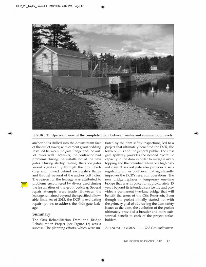
FIGURE 11. Upstream view of the completed dam between winter and summer pool levels.
CEP_28_Taylor_Layout 1 2/13/2014 4:02 PM Page 17

18 CIVIL ENGINEERING PRACTICE 2013
tal, Inc., was the firm that provided the inspection ofthe dam and all engineering analyses and reports onthis project. Working with the DCR, GZA was proj-ect manager. GZA retained Wright-Pierce ofTopsham, Maine, to provide structural, mechanicaland electrical engineering design services for the newcrest gate and for two new slide gates in the outlettower. Under a separate contract, MassDOTengaged Amman Whitney of Boston, Massachusetts,to perform the bridge design. Contractor for the proj-ect was MIG Corporation of Acton, Massachusetts.The bridge superstructure was manufactured by FortMiller Company, Inc., of Schuylerville, New York.The crest gate was fabricated by Rodney Hunt ofOrange, Massachusetts.
MATTHEW A. TAYLOR (bio tocome).
JOHN G. DELANO (bio to come).
CEP_28_Taylor_Layout 1 2/13/2014 4:02 PM Page 18