Embed Size (px)
Citation preview

IFB NO. W912P8-09-B-0035
US Army Corps of Engineers ® New Orleans District Hurricane Protection Office
Grand Isle and Vicinity Hurricane Protection Project Stations 0+00 to 386+00 along Grand Isle Beach
Rehabilitation of Hurricane Gustav and Hurricane Ike Damage Jefferson Parish, Louisiana W912P8-09-B-0035 February 2009 ED 09-075

SOLICITATION: W912P8-09-B-0035 FOR: Grand Isle and Vicinity, Hurricane Protection Project, Rehabilitation of Hurricane Gustav and
Hurricane Ike Damage TO OPEN: I. NOTE THE AFFIRMATIVE ACTION PROGRAM REQUIREMENT OF THE EQUAL OPPORTUNITY CLAUSE WHICH MAY APPLY TO THE CONTRACT RESULTING FROM THIS SOLICITATION. II. NOTE THE CERTIFICATION OF NONSEGREGATED FACILITIES IN THIS SOLICITATION.
Bidders, offerors and applicants are cautioned to note the "Certification of Non-segregated Facilities" in the solicitation. Failure of a bidder or offeror to agree to the certification will render his bid or offer non-responsive to the terms of solicitations involving awards of contracts exceeding $10,000 which are not exempt from the provisions of the Equal Opportunity clause.
III. (DFARS 204.7302) Prospective contractors must be registered in the CCR database prior to
award of a contract. By regulation, no DoD contract can be awarded to any contractor that is not registered in the Department of Defense “Central Contractor Registration” (CCR). If your company is not currently registered in the CCR you may do so by simply going to http://www.ccr.gov. You will be required to provide your company’s Dun and Bradstreet number. If you do not already have a D&B number, one can be obtained simply by calling Dun and Bradstreet at (800) 333-0505.
BIDDERS MUST PROVIDE FULL, ACCURATE AND COMPLETE INFORMATION AS REQUIRED BY THIS SOLICITATION AND ITS ATTACHMENTS. THE PENALTY FOR MAKING FALSE STATEMENTS IN BIDS IS PRESCRIBED IN 18 U.S.C. 1001. (FAR 52.214-4 APR 1984) DESCRIPTION AND MAGNITUDE OF WORK: Install geotextile tube along dune centerline. Replenish the beach and dune with dredged (by the Contractor) sand. Construct pedestrian crossovers and emergency vehicle ramps. Plant dune vegetation. CAUTION TO BIDDERS: In delivery of hand-carried bids, bidders are cautioned to allow sufficient time for delays which may be encountered as a result of frequent trains which are subject to block all access roads to place of bid opening for various lengths of time. Such delays DO NOT permit acceptance or consideration of late bids. NOTE: ALL WORK UNDER THESE SPECIFICATIONS SHALL BE PERFORMED IN ACCORDANCE WITH THE PROVISIONS OF EM 385-1-1 "CORPS OF ENGINEERS SAFETY AND HEALTH REQUIREMENTS MANUAL", DATED SEPTEMBER, 2008. ATTENTION: Effective January 1, 2005, all Contractors who submit an offer/bid are required to register in the Online Representations and Certifications Applications (ORCA). See FAR Clauses 25.204-7 and 52.204-8 for required information. The Web site for ORCA is http://orca.bpn.gov. ORCA registration replaces some of the Representations and Certifications normally found in Section 0700.
ED 09-075

MAIN TABLE OF CONTENTS
00010 Solicitation, Offer and Award (SF-1442) Bidding Schedule 00010-1 thru 1 00700 Contract Clause Inserts 00700-1 thru 17
Division 1 - GENERAL REQUIREMENTS 01100 General Provisions 01100-1 thru 19 01200 Measurement and Payment 01200-1 thru 4 01321 Construction Progress Documentation 01321-1 thru 4 01330 Submittal Procedures 01330-1 thru 6 01331 Surveys 01331-1 thru 5 01352 Environmental Protection 01352-1 thru 11 01451 Contractor Quality Control 01451-1 thru 12 01452 Quality Control Systems (QCS) 01452-1 thru 8 01780 Closeout Submittals 01780-1 thru 6
Division 2 - SITE WORK
02231 Clearing and Grubbing 02231-1 thru 3 02235 Excavation of Existing Dune 02235-1 thru 2 02245 Polyurea Coated Geotextile Tube, 02245-1 thru 18 Scour Apron, and Anchor Tubes 02333 Beach and Dune Sand Cover 02333-1 thru 5 02382 Emergency Vehicle Crossovers 02382-1 thru 4 02482 Dredging in the Borrow Area 02482-1 thru 8 02630 Pedestrian Walkway Dune Crossings 02630-1 thru 4 02930 Dune Planting and Sand Fences 02930-1 thru 11
MTC-a ED 09-075
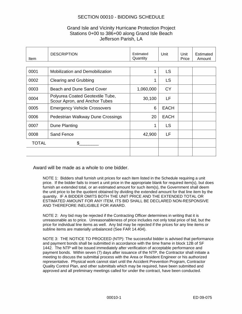
SECTION 00010 - BIDDING SCHEDULE
Grand Isle and Vicinity Hurricane Protection Project Stations 0+00 to 386+00 along Grand Isle Beach
Jefferson Parish, LA
Item
DESCRIPTION
Estimated Quantity
Unit
Unit Price
Estimated Amount
00010-1 ED 09-075
0001 Mobilization and Demobilization 1 LS
0002 Clearing and Grubbing 1 LS
0003 Beach and Dune Sand Cover 1,060,000 CY
0004 Polyurea Coated Geotextile Tube, Scour Apron, and Anchor Tubes 30,100 LF
0005 Emergency Vehicle Crossovers 6 EACH
0006 Pedestrian Walkway Dune Crossings 20 EACH
0007 Dune Planting 1 LS
0008 Sand Fence 42,900 LF
TOTAL $________
Award will be made as a whole to one bidder.
NOTE 1: Bidders shall furnish unit prices for each item listed in the Schedule requiring a unit price. If the bidder fails to insert a unit price in the appropriate blank for required item(s), but does furnish an extended total, or an estimated amount for such item(s), the Government shall deem the unit price to be the quotient obtained by dividing the extended amount for that line item by the quantity. IF A BIDDER OMITS BOTH THE UNIT PRICE AND THE EXTENDED TOTAL OR ESTIMATED AMOUNT FOR ANY ITEM, ITS BID SHALL BE DECLARED NON-RESPONSIVE AND THEREFORE INELIGIBLE FOR AWARD. NOTE 2: Any bid may be rejected if the Contracting Officer determines in writing that it is unreasonable as to price. Unreasonableness of price includes not only total price of bid, but the price for individual line items as well. Any bid may be rejected if the prices for any line items or subline items are materially unbalanced (See FAR 14.404). NOTE 3: THE NOTICE TO PROCEED (NTP): The successful bidder is advised that performance and payment bonds shall be submitted in accordance with the time frame in block 12B of SF 1442. The NTP will be issued immediately after verification of acceptable performance and payment bonds. Within seven (7) days after issuance of the NTP, the Contractor shall initiate a meeting to discuss the submittal process with the Area or Resident Engineer or his authorized representative. Physical work cannot start until the Accident Prevention Program, Contractor Quality Control Plan, and other submittals which may be required, have been submitted and approved and all preliminary meetings called for under the contract, have been conducted.

Section Table of Contents
SECTION 00700 – CONTRACT CLAUSE INSERTS 1. COMMENCEMENT, PROSECUTION, AND COMPLETION OF WORK 1 2. LIQUIDATED DAMAGES 1 3. CONTRACT DRAWINGS AND SPECIFICATIONS 1 4. EQUIPMENT OWNERSHIP AND OPERATING EXPENSE SCHEDULE 3 5. PHYSICAL DATA 4 6. LAYOUT OF WORK 5 7. PAYMENT FOR MOBILIZATION AND DEMOBILIZATION 5 8. PERFORMANCE OF WORK BY CONTRACTOR 6 9. OBSTRUCTION OF NAVIGABLE WATERWAYS 6 10. AVAILABILITY AND USE OF UTILITY SERVICES 7 11 SCHEDULES FOR CONSTRUCTION CONTRACTS 7 12 FIXED-PRICE CONSTRUCTION 8 13 PERMITS AND RESPONSIBILITES 9 14 CHANGES 10 15 ACCIDENT PREVENTION 11 16 SUSPENSION OF WORK 12 17 DIFFERING SITE CONDITIONS 13 18 CLEANING UP 13 19 PROTECTION OF EXISTING VEGETATION, STRUCTURES, EQUIPMENT, UTILITIES, AND IMPROVEMENTS 14 20 OPERATIONS AND STORAGE AREAS 14 21 INPSECTION OF CONSTRUCTION 15 22 SITE INVESTAGATION AND CONDITIONS AFFECTING THE WORK 16
00700Inserts-a ED 09-075

SECTION 00700 – CONTRACT CLAUSE INSERTS 1. COMMENCEMENT, PROSECUTION, AND COMPLETION OF WORK (FAR 52.211-10 - APR 1984)
The Contractor shall be required to
(a) Commence work under this contract within 10 calendar days after the date the Contractor receives the notice to proceed,
(b) Prosecute the work diligently, using multiple work crews if necessary, and
(c) Complete all work within 170 days after the Contractor receives the notice to proceed. The time stated for completion does not include demobilization, final cleanup of the work area, or dune planting. The Contractor may commence dune planting work on February 1st, 2010 and must complete work within 60 days after February 1st.
(End of Clause)
NOTE. The Contractor is hereby informed that time allowed for completion of work has been established as the shortest reasonable duration and that he/she shall make any and all provisions necessary (multiple crews, overtime, concurrent operations, etc.) to accomplish the work within the available time period.
2. LIQUIDATED DAMAGES - CONSTRUCTION (FAR 52.211-12 – SEPT 2000)
(a) If the Contractor fails to complete the work within the time specified in the contract, the Contractor shall pay liquidated damages to the Government in the amount of $5,000.00 for each calendar day of delay until the work is completed or accepted. (b) If the Government terminates the Contractor's right to proceed, liquidated damages will continue to accrue until the work is completed. These liquidated damages are in addition to excess costs of repurchase under the Termination clause.
(End of Clause)
3. CONTRACT DRAWINGS AND SPECIFICATIONS (DFARS 252.236-7001 – AUG 2000)
(a) The Government will provide to the Contractor, without charge, one set of contract drawings and specifications, except publications incorporated into the technical provisions by reference, in electronic or paper media as chosen by the Contracting Officer.
00700Inserts-1 Ed 09-075

(b) The Contractor shall -- (1) Check all drawings furnished immediately upon receipt; (2) Compare all drawings and verify the figures before laying out the work; (3) Promptly notify the Contracting Officer of any discrepancies; (4) Be responsible for any errors that might have been avoided by complying with this paragraph (b); and (5) Reproduce and print contract drawings and specifications as needed.
(c) In general --
(1) Large-scale drawings shall govern small-scale drawings; and (2) The Contractor shall follow figures marked on drawings in preference to scale measurements.
(d) Omissions from the drawings or specifications or the mis-description of details of work that are manifestly necessary to carry out the intent of the drawings and specifications, or that are customarily performed, shall not relieve the Contractor from performing such omitted or mis-described details of the work. The Contractor shall perform such details as if fully and correctly set forth and described in the drawings and specifications. (e) The work shall conform to the specifications and the contract drawings identified on the following index of drawings:
Title File Drawing No. Grand Isle and Vicinity H-16-46949 G1-G4 Hurricane Protection Project C1-C14 Rehabilitation of Hurricane C301-C315 Gustav and Hurricane Ike Damage F1-F4 Jefferson Parish, LA H1
(End of Clause)
00700Inserts-2 Ed 09-075

4. EQUIPMENT OWNERSHIP AND OPERATING EXPENSE SCHEDULE (EFARS 52.231-5000 - MAR 95)
(a) This clause does not apply to terminations. See EFARS 52.249-5000, Basis For Settlement of Proposals, and FAR Part 49. (b) Allowable cost for construction and marine plant and equipment in sound workable condition, owned or controlled and furnished by a Contractor or Subcontractor at any tier shall be based on actual cost data for each piece of equipment or groups of similar serial and series for which the Government can determine both ownership and operating costs from the Contractor's accounting records. When both ownership and operating costs cannot be determined for any piece of equipment or groups of similar serial or series equipment from the Contractor's accounting records, costs for that equipment shall be based upon the applicable provisions of EP 1110-1-8, "Construction Equipment Ownership and Operating Expense Schedule," Region III. Working conditions shall be considered to be average for determining equipment rates using the schedule unless specified otherwise by the Contracting Officer. For equipment not included in the schedule, rates for comparable pieces of equipment may be used or a rate may be developed using the formula provided in the schedule. For forward pricing, the schedule in effect at the time of negotiations shall apply. For retroactive pricing, the schedule in effect at the time the work was performed shall apply. (c) Equipment rental costs are allowable, subject to the provisions of FAR 31.105(d) (ii) and FAR 31.205-36. Rates for equipment rented from an organization under common control, lease-purchase arrangements, and sale-leaseback arrangements will be determined using the schedule, except that actual rates will be used for equipment leased from an organization under common control that has an established practice of leasing the same or similar equipment to unaffiliated lessees. (d) When actual equipment costs are proposed and the total amount of the pricing action exceeds the small purchase threshold, the Contracting Officer shall request the Contractor to submit either certified cost or pricing data, or partial/limited data, as appropriate.
(End of Clause) NOTE1: Costs for repairs or overhauling are not allowed. NOTE 2: A copy of the "EQUIPMENT OWNERSHIP AND OPERATING EXPENSE SCHEDULE CD can be obtained from the Government Printing Office (GPO) by calling (202)512-1800 or through the Internet site www.gpoaccess.gov. Also any references in the paragraph to the manual should be changed to reference the CD.
00700Inserts-3 Ed 09-075

5. PHYSICAL DATA (FAR 52.236-4 - APR 1984)
Data and information furnished or referred to below is for the Contractor's information. The Government shall not be responsible for any interpretation of or conclusion drawn from the data or information by the Contractor.
(a) The indications of physical conditions on the drawings and in the specifications are the result of site investigations by surveys and borings. Field notes, graphic boring logs, field and laboratory test results, and other data on which this information is based are available at U.S. Army Engineer District, New Orleans, Corps of Engineers, Attn: CEMVN-ED, P.O. Box 60267, New Orleans, Louisiana 70160-0267, and access thereto may be had upon request. (b) Weather Conditions. Data on weather conditions may be obtained from the National Weather Service. (c) Transportation Facilities. The work area can be reached by traveling south on LA Hwy. 1 to the town of Grand Isle, LA. Access to the beach will be from public streets shown on the drawings. Travel to the area by crew boats and planes equipped with pontoons is possible.
(d) Condition of Channel. Barataria Pass on the eastern end of Grand Isle is maintained with a 12’ x 125’ channel. The channel is properly equipped by the Coast Guard with buoys and navigation lights. Caminada Pass on the western end of the island is not maintained as a navigation channel. (e) Channel Traffic. Boat traffic in the borrow areas consist of pleasure craft, fishing vessels, crew boats, and shallow draft barges. (f) Obstruction of Channel. The Government will not undertake to keep Barataria Pass free from vessels or other obstructions, except to the extent of such regulations, if any, as may be prescribed by the Secretary of the Army, in accordance with the provisions of Section 7 of the River and Harbor Act approved 8 August 1917. The Contractor will be required to conduct the work in such a manner as to obstruct navigation as little as possible, and in case the Contractor’s plant so obstructs the channel as to make difficult or endanger the passage of vessels, said plant shall be promptly moved on the approach of any vessel to the extent as may be necessary to afford a practicable passage. Upon completion of the work, the Contractor shall promptly remove his plant, including ranges, buoys, piles and other markers placed by him under the contract in navigable water or on shore. (g) Estimates of quantities involved in certain items of work for which bids are being solicited on a lump sum or job basis have been made for the use of the Government. Copies of these quantity estimates may be viewed/obtained by contacting the District Commander, Attn: Contracting Officer, same address as
00700Inserts-4 Ed 09-075

stated in subparagraph (a) above. It is expressly understood that the accuracy of these estimates is in no way warranted and that the furnishing of this information to a bidder will not relieve him of his responsibility to estimate the quantities involved.
(End of Clause)
6. LAYOUT OF WORK (FAR 52.236-17 - APR 1984)
The Contractor shall lay out its work from Government-established base lines as indicated on the drawings, and shall be responsible for all measurements in connection with the layout. The Contractor shall furnish, at its own expense, all stakes, templates, platforms, equipment, tools, materials, and labor required to lay out any part of the work. The Contractor shall be responsible for executing the work to the lines and grades that may be established or indicated by the Contracting Officer. The Contractor shall also be responsible for maintaining and preserving all stakes and other marks established by the Contracting Officer until authorized to remove them. If such marks are destroyed by the Contractor or through its negligence before their removal is authorized, the Contracting Officer may replace them and deduct the expense of the replacement from any amounts due or to become due to the Contractor.
(End of Clause) 7. PAYMENT FOR MOBILIZATION AND DEMOBILIZATION (DFARS 252.236-7004 - DEC 1991)
(a) The Government will pay all costs for the mobilization and demobilization of all of the Contractor's plant and equipment at the contract lump sum price for this item.
(1) Eighty percent (80%) of the lump sum price upon completion of the Contractor's mobilization at the work site. (2) The remaining twenty percent (20%) upon completion of demobilization.
(b) The Contracting Officer may require the Contractor to furnish cost data to justify this portion of the bid if the Contracting Officer believes that the percentages in paragraphs (a) (1) and (a) (2) of this clause do not bear a reasonable relation to the cost of the work in this contract.
(1) Failure to justify such price to the satisfaction of the Contracting Officer will result in payment, as determined by the Contracting Officer, of-
(i) Actual mobilization costs at completion of mobilization;
00700Inserts-5 Ed 09-075

(ii) Actual demobilization costs at completion of demobilization; and (iii) The remainder of this item in the final payment under this contract.
(2) The Contracting Officer's determination of the actual costs in paragraph (b) (1) of this clause is not subject to appeal.
(End of Clause)
8. PERFORMANCE OF WORK BY CONTRACTOR (FAR 52.236-1 - APR 1984)
The Contractor shall perform on the site, and with its own organization, work equivalent to at least twenty percent (20%) of the total amount of the work to be performed under the contract. This percentage may be reduced by a supplemental agreement to this contract, if, during performing the work, the Contractor requests a reduction and the Contracting Officer determines that the reduction would be to the advantage of the Government.
(End of Clause) 9. OBSTRUCTION OF NAVIGABLE WATERWAYS (DFARS 252.236-7002 - DEC 91)
(a) The Contractor shall:
(1) Promptly recover and remove any material, plant, machinery, or appliance which the Contractor loses, dumps, throws overboard, sinks, or misplaces, and which, in the opinion of the Contracting Officer, may be dangerous to or obstruct navigation; (2) Give immediate notice, with description and locations of any such obstructions, to the Contracting Officer; and (3) When required by the Contracting Officer, mark or buoy such obstructions until the same are removed.
(b) The Contracting Officer may:
(1) Remove the obstructions by contract or otherwise should the Contractor refuse, neglect, or delay compliance with paragraph (a) of this clause; and (2) Deduct the cost of removal from any monies due or to become due to the Contractor; or
00700Inserts-6 Ed 09-075

(3) Recover the cost of removal under the Contractor's bond.
(c) The Contractor's liability for the removal of a vessel wrecked or sunk without fault or negligence is limited to that provided in Sections 15, 19, and 20 of the River and Harbor Act of March 3, 1899 (33 U.S.C.410 et.seq.).
(End of Clause) 10. AVAILABILITY AND USE OF UTILITY SERVICES (FAR 52.236-14 - 1984 APR)
(a) The Contractor, at its expense and in a workmanlike manner satisfactory to the Contracting Officer and all local ordinances, shall install and maintain all necessary temporary connections and distribution lines, and all meters required to measure the amount of each utility used for the purpose of determining charges. Before final acceptance of the work by the Government, the Contractor shall remove all the temporary connections, distribution lines, meters, and associated paraphernalia.
(End of Clause) 11. SCHEDULES FOR CONSTRUCTION CONTRACTS (FAR 52.236-15 - APR 1984)
(a) The Contractor shall, within five days after the work commences on the contract or another period of time determined by the Contracting Officer, prepare and submit to the Contracting Officer for approval three copies of a practicable schedule showing the order in which the Contractor proposes to perform the work, and the dates on which the Contractor contemplates starting and completing the several salient features of the work (including acquiring materials, plant, and equipment). The schedule shall be in the form of a progress chart of suitable scale to indicate appropriately the percentage of work scheduled for completion by any given date during the period. If the Contractor fails to submit a schedule within the time prescribed, the Contracting Officer may withhold approval of progress payments until the Contractor submits the required schedule. (b) The Contractor shall enter the actual progress on the chart as directed by the Contracting Officer, and upon doing so shall immediately deliver three copies of the annotated schedule to the Contracting Officer. If, in the opinion of the Contracting Officer, the Contractor falls behind the approved schedule, the Contractor shall take steps necessary to improve its progress, including those that may be required by the Contracting Officer, without additional cost to the Government. In this circumstance, the Contracting Officer may require the Contractor to increase the number of shifts, overtime operations, days of work, and/or the amount of construction plant, and to submit for approval any
00700Inserts-7 Ed 09-075

supplementary schedule or schedules in chart form as the Contracting Officer deems necessary to demonstrate how the approved rate of progress will be regained. (c) Failure of the Contractor to comply with the requirements of the Contracting Officer under this clause shall be grounds for a determination by the Contracting Officer that the Contractor is not prosecuting the work with sufficient diligence to ensure completion within the time specified in the contract. Upon making this determination, the Contracting Officer may terminate the Contractor’s right to proceed with the work, or any separable part of it, in accordance with the default terms of this contract.
(End of Clause)
12. FIXED-PRICE CONSTRUCTION (FAR 52.249-10-APR 1984) (a) If the Contractor refuses or fails to prosecute the work or any separable part, with the diligence that will insure its completion within the time specified in this contract including any extension, or fails to complete the work within this time, the Government may, by written notice to the Contractor, terminate the right to proceed with the work (or the separable part of the work) that has been delayed. In this event, the Government may take over the work and complete it by contract or otherwise, and may take possession of and use any materials, appliances, and plant on the work site necessary for completing the work. The Contractor and its sureties shall be liable for any damage to the Government resulting from the Contractor’s refusal or failure to complete the work within the specified time, whether or not the Contractor’s right to proceed with the work is terminated. This liability includes any increased costs incurred by the Government in completing the work. (b) The Contractor’s right to proceed shall not be terminated nor the Contractor charged with damages under this clause, if—
(1) The delay in completing the work arises from unforeseeable causes beyond the control and without the fault or negligence of the Contractor. Examples of such causes include—
(i) Acts of God or of the public enemy, (ii) Acts of the Government in either its sovereign or contractual capacity, (iii) Acts of another Contractor in the performance of a contract with the Government, (iv) Fires,
00700Inserts-8 Ed 09-075

(v) Floods, (vi) Epidemics, (vii) Quarantine restrictions, (viii) Strikes, (ix) Freight embargoes, (x) Unusually severe weather, or (xi) Delays of subcontractors or suppliers at any tier arising from unforeseeable causes beyond the control and without the fault or negligence of both the Contractor and the subcontractors or suppliers; and
(2) The Contractor, within 10 days from the beginning of any delay (unless extended by the Contracting Officer), notifies the Contracting Officer in writing of the causes of delay. The Contracting Officer shall ascertain the facts and the extent of delay. If, in the judgment of the Contracting Officer, the findings of fact warrant such action, the time for completing the work shall be extended. The findings of the Contracting Officer shall be final and conclusive on the parties, but subject to appeal under the Disputes clause.
(c) If, after termination of the Contractor’s right to proceed, it is determined that the Contractor was not in default, or that the delay was excusable, the rights and obligations of the parties will be the same as if the termination had been issued for the convenience of the Government. (d) The rights and remedies of the Government in this clause are in addition to any other rights and remedies provided by law or under this contract.
(End of Clause)
13. PERMITS AND RESPONSIBILITES (FAR 52.236-7-NOV 1991) The Contractor shall, without additional expense to the Government, be responsible for obtaining any necessary licenses and permits, and for complying with any Federal, State, and municipal laws, codes, and regulations applicable to the performance of the work. The Contractor shall also be responsible for all damages to persons or property that occur as a result of the Contractor’s fault or negligence. The Contractor shall also be responsible for all materials delivered and work performed until completion and acceptance of the entire work, except
00700Inserts-9 Ed 09-075

for any completed unit of work which may have been accepted under the contract.
(End of Clause)
14. CHANGES (FAR 52.243-4-JUNE 2007) a) The Contracting Officer may, at any time, without notice to the sureties, if any, by written order designated or indicated to be a change order, make changes in the work within the general scope of the contract, including changes—
(1) In the specifications (including drawings and designs); (2) In the method or manner of performance of the work; (3) In the Government-furnished property or services; or (4) Directing acceleration in the performance of the work. (b) Any other written or oral order (which, as used in this paragraph (b), includes direction, instruction, interpretation, or determination) from the Contracting Officer that causes a change shall be treated as a change order under this clause; Provided, that the Contractor gives the Contracting Officer written notice stating—
(1) The date, circumstances, and source of the order; and (2) That the Contractor regards the order as a change order.
(c) Except as provided in this clause, no order, statement, or conduct of the Contracting Officer shall be treated as a change under this clause or entitle the Contractor to an equitable adjustment. (d) If any change under this clause causes an increase or decrease in the Contractor’s cost of, or the time required for, the performance of any part of the work under this contract, whether or not changed by any such order, the Contracting Officer shall make an equitable adjustment and modify the contract in writing. However, except for an adjustment based on defective specifications, no adjustment for any change under paragraph (b) of this clause shall be made for any costs incurred more than 20 days before the Contractor gives written notice as required. In the case of defective specifications for which the Government is responsible, the equitable adjustment shall include any increased cost reasonably incurred by the Contractor in attempting to comply with the defective specifications. (e) The Contractor must assert its right to an adjustment under this clause within 30 days after (1) receipt of a written change order under paragraph (a) of this
00700Inserts-10 Ed 09-075

clause or (2) the furnishing of a written notice under paragraph (b) of this clause, by submitting to the Contracting Officer a written statement describing the general nature and amount of the proposal, unless this period is extended by the Government. The statement of proposal for adjustment may be included in the notice under paragraph (b) of this clause. (f) No proposal by the Contractor for an equitable adjustment shall be allowed if asserted after final payment under this contract.
(End of Clause)
15. ACCIDENT PREVENTION (FAR 52.236-13-NOV 2001) a) The Contractor shall provide and maintain work environments and procedures which will—
(1) Safeguard the public and Government personnel, property, materials, supplies, and equipment exposed to Contractor operations and activities; (2) Avoid interruptions of Government operations and delays in project completion dates; and (3) Control costs in the performance of this contract.
(b) For these purposes on contracts for construction or dismantling, demolition, or removal of improvements, the Contractor shall—
(1) Provide appropriate safety barricades, signs, and signal lights; (2) Comply with the standards issued by the Secretary of Labor at 29 CFR Part 1926 and 29 CFR Part 1910; and (3) Ensure that any additional measures the Contracting Officer determines to be reasonably necessary for the purposes are taken.
(c) If this contract is for construction or dismantling, demolition or removal of improvements with any Department of Defense agency or component, the Contractor shall comply with all pertinent provisions of the latest version of U.S. Army Corps of Engineers Safety and Health Requirements Manual, EM 385-1-1, in effect on the date of the solicitation. (d) Whenever the Contracting Officer becomes aware of any noncompliance with these requirements or any condition which poses a serious or imminent danger to the health or safety of the public or Government personnel, the Contracting Officer shall notify the Contractor orally, with written confirmation, and request immediate initiation of corrective action. This notice, when delivered to the
00700Inserts-11 Ed 09-075

Contractor or the Contractor’s representative at the work site, shall be deemed sufficient notice of the noncompliance and that corrective action is required. After receiving the notice, the Contractor shall immediately take corrective action. If the Contractor fails or refuses to promptly take corrective action, the Contracting Officer may issue an order stopping all or part of the work until satisfactory corrective action has been taken. The Contractor shall not be entitled to any equitable adjustment of the contract price or extension of the performance schedule on any stop work order issued under this clause. (e) The Contractor shall insert this clause, including this paragraph (e), with appropriate changes in the designation of the parties, in subcontracts.
(End of Clause)
16. SUSPENSION OF WORK (FAR 52.242-14-APR 1984) a) The Contracting Officer may order the Contractor, in writing, to suspend, delay, or interrupt all or any part of the work of this contract for the period of time that the Contracting Officer determines appropriate for the convenience of the Government. (b) If the performance of all or any part of the work is, for an unreasonable period of time, suspended, delayed, or interrupted (1) by an act of the Contracting Officer in the administration of this contract, or (2) by the Contracting Officer’s failure to act within the time specified in this contract (or within a reasonable time if not specified), an adjustment shall be made for any increase in the cost of performance of this contract (excluding profit) necessarily caused by the unreasonable suspension, delay, or interruption, and the contract modified in writing accordingly. However, no adjustment shall be made under this clause for any suspension, delay, or interruption to the extent that performance would have been so suspended, delayed, or interrupted by any other cause, including the fault or negligence of the Contractor, or for which an equitable adjustment is provided for or excluded under any other term or condition of this contract. (c) A claim under this clause shall not be allowed—
(1) For any costs incurred more than 20 days before the Contractor shall have notified the Contracting Officer in writing of the act or failure to act involved (but this requirement shall not apply as to a claim resulting from a suspension order); and (2) Unless the claim, in an amount stated, is asserted in writing as soon as practicable after the termination of the suspension, delay, or interruption, but not later than the date of final payment under the contract.
(End of Clause)
00700Inserts-12 Ed 09-075

17. DIFFERING SITE CONDITIONS (FAR 52.236-2-APR 1984)
(a) The Contractor shall promptly, and before the conditions are disturbed, give a written notice to the Contracting Officer of—
(1) Subsurface or latent physical conditions at the site which differ materially from those indicated in this contract; or (2) Unknown physical conditions at the site, of an unusual nature, which differ materially from those ordinarily encountered and generally recognized as inhering in work of the character provided for in the contract.
(b) The Contracting Officer shall investigate the site conditions promptly after receiving the notice. If the conditions do materially so differ and cause an increase or decrease in the Contractor’s cost of, or the time required for, performing any part of the work under this contract, whether or not changed as a result of the conditions, an equitable adjustment shall be made under this clause and the contract modified in writing accordingly. (c) No request by the Contractor for an equitable adjustment to the contract under this clause shall be allowed, unless the Contractor has given the written notice required; provided, that the time prescribed in paragraph (a) of this clause for giving written notice may be extended by the Contracting Officer. (d) No request by the Contractor for an equitable adjustment to the contract for differing site conditions shall be allowed if made after final payment under this contract.
(End of Clause)
18. CLEANING UP (FAR 52.236-2-APR 1984) The Contractor shall at all times keep the work area, including storage areas, free from accumulations of waste materials. Before completing the work, the Contractor shall remove from the work and premises any rubbish, tools, scaffolding, equipment, and materials that are not the property of the Government. Upon completing the work, the Contractor shall leave the work area in a clean, neat, and orderly condition satisfactory to the Contracting Officer.
(End of Clause)
00700Inserts-13 Ed 09-075

19. PROTECTION OF EXISTING VEGETATION, STRUCTURES, EQUIPMENT, UTILITIES, AND IMPROVEMENTS (FAR 52.236-9-APR 1984)
(a) The Contractor shall preserve and protect all structures, equipment, and vegetation (such as trees, shrubs, and grass) on or adjacent to the work site, which are not to be removed and which do not unreasonably interfere with the work required under this contract. The Contractor shall only remove trees when specifically authorized to do so, and shall avoid damaging vegetation that will remain in place. If any limbs or branches of trees are broken during contract performance, or by the careless operation of equipment, or by workmen, the Contractor shall trim those limbs or branches with a clean cut and paint the cut with a tree-pruning compound as directed by the Contracting Officer. (b) The Contractor shall protect from damage all existing improvements and utilities (1) at or near the work site, and (2) on adjacent property of a third party, the locations of which are made known to or should be known by the Contractor. The Contractor shall repair any damage to those facilities, including those that are the property of a third party, resulting from failure to comply with the requirements of this contract or failure to exercise reasonable care in performing the work. If the Contractor fails or refuses to repair the damage promptly, the Contracting Officer may have the necessary work performed and charge the cost to the Contractor.
(End of Clause) 20. OPERATIONS AND STORAGE AREAS (FAR 52.236-10-APR 1984)
(a) The Contractor shall confine all operations (including storage of materials) on Government premises to areas authorized or approved by the Contracting Officer. The Contractor shall hold and save the Government, its officers and agents, free and harmless from liability of any nature occasioned by the Contractor’s performance. (b) Temporary buildings (e.g., storage sheds, shops, offices) and utilities may be erected by the Contractor only with the approval of the Contracting Officer and shall be built with labor and materials furnished by the Contractor without expense to the Government. The temporary buildings and utilities shall remain the property of the Contractor and shall be removed by the Contractor at its expense upon completion of the work. With the written consent of the Contracting Officer, the buildings and utilities may be abandoned and need not be removed. (c) The Contractor shall, under regulations prescribed by the Contracting Officer, use only established roadways, or use temporary roadways constructed by the Contractor when and as authorized by the Contracting Officer. When materials are transported in prosecuting the work, vehicles shall not be loaded beyond the loading capacity recommended by the manufacturer of the vehicle or prescribed
00700Inserts-14 Ed 09-075

by any Federal, State, or local law or regulation. When it is necessary to cross curbs or sidewalks, the Contractor shall protect them from damage. The Contractor shall repair or pay for the repair of any damaged curbs, sidewalks, or roads.
(End of Clause)
21. INSPECTION OF CONSTRUCTION (FAR 52.246-12-AUG 1996)
(a) Definition. “Work” includes, but is not limited to, materials, workmanship, and manufacture and fabrication of components. (b) The Contractor shall maintain an adequate inspection system and perform such inspections as will ensure that the work performed under the contract conforms to contract requirements. The Contractor shall maintain complete inspection records and make them available to the Government. All work shall be conducted under the general direction of the Contracting Officer and is subject to Government inspection and test at all places and at all reasonable times before acceptance to ensure strict compliance with the terms of the contract. (c) Government inspections and tests are for the sole benefit of the Government and do not—
(1) Relieve the Contractor of responsibility for providing adequate quality control measures; (2) Relieve the Contractor of responsibility for damage to or loss of the material before acceptance; (3) Constitute or imply acceptance; or (4) Affect the continuing rights of the Government after acceptance of the completed work under paragraph (i) of this section.
(d) The presence or absence of a Government inspector does not relieve the Contractor from any contract requirement, nor is the inspector authorized to change any term or condition of the specification without the Contracting Officer’s written authorization. (e) The Contractor shall promptly furnish, at no increase in contract price, all facilities, labor, and material reasonably needed for performing such safe and convenient inspections and tests as may be required by the Contracting Officer. The Government may charge to the Contractor any additional cost of inspection or test when work is not ready at the time specified by the Contractor for inspection or test, or when prior rejection makes reinspection or retest necessary. The Government shall perform all inspections and tests in a manner that will not
00700Inserts-15 Ed 09-075

unnecessarily delay the work. Special, full size, and performance tests shall be performed as described in the contract. (f) The Contractor shall, without charge, replace or correct work found by the Government not to conform to contract requirements, unless in the public interest the Government consents to accept the work with an appropriate adjustment in contract price. The Contractor shall promptly segregate and remove rejected material from the premises. (g) If the Contractor does not promptly replace or correct rejected work, the Government may—
(1) By contract or otherwise, replace or correct the work and charge the cost to the Contractor; or (2) Terminate for default the Contractor’s right to proceed.
(h) If, before acceptance of the entire work, the Government decides to examine already completed work by removing it or tearing it out, the Contractor, on request, shall promptly furnish all necessary facilities, labor, and material. If the work is found to be defective or nonconforming in any material respect due to the fault of the Contractor or its subcontractors, the Contractor shall defray the expenses of the examination and of satisfactory reconstruction. However, if the work is found to meet contract requirements, the Contracting Officer shall make an equitable adjustment for the additional services involved in the examination and reconstruction, including, if completion of the work was thereby delayed, an extension of time. (i) Unless otherwise specified in the contract, the Government shall accept, as promptly as practicable after completion and inspection, all work required by the contract or that portion of the work the Contracting Officer determines can be accepted separately. Acceptance shall be final and conclusive except for latent defects, fraud, gross mistakes amounting to fraud, or the Government’s rights under any warranty or guarantee.
(End of Clause)
22. SITE INVESTAGATION AND CONDITIONS AFFECTING THE WORK (FAR 52.236-3-APR 1984)
(a) The Contractor acknowledges that it has taken steps reasonably necessary to ascertain the nature and location of the work, and that it has investigated and satisfied itself as to the general and local conditions which can affect the work or its cost, including but not limited to (1) conditions bearing upon transportation, disposal, handling, and storage of materials; (2) the availability of labor, water, electric power, and roads; (3) uncertainties of weather, river stages, tides, or
00700Inserts-16 Ed 09-075

00700Inserts-17 Ed 09-075
similar physical conditions at the site; (4) the conformation and conditions of the ground; and (5) the character of equipment and facilities needed preliminary to and during work performance. The Contractor also acknowledges that it has satisfied itself as to the character, quality, and quantity of surface and subsurface materials or obstacles to be encountered insofar as this information is reasonably ascertainable from an inspection of the site, including all exploratory work done by the Government, as well as from the drawings and specifications made a part of this contract. Any failure of the Contractor to take the actions described and acknowledged in this paragraph will not relieve the Contractor from responsibility for estimating properly the difficulty and cost of successfully performing the work, or for proceeding to successfully perform the work without additional expense to the Government. (b) The Government assumes no responsibility for any conclusions or interpretations made by the Contractor based on the information made available by the Government. Nor does the Government assume responsibility for any understanding reached or representation made concerning conditions which can affect the work by any of its officers or agents before the execution of this contract, unless that understanding or representation is expressly stated in this contract.
(End of Clause)

Section Table of Contents
SECTION 01100 - GENERAL PROVISIONS 1. TIME EXTENSIONS FOR UNUSUALLY SEVERE WEATHER 1 2. DAMAGE TO WORK 2 3. SAFETY PROVISIONS 2 4. QUALITY ASSURANCE REPRESENTATIVE’S FIELD OFFICE 8 5. PROJECT SIGN 9 6. RIGHTS-OF-WAY 9 7. CERTIFICATES OF COMPLIANCE 11 8. ENVIRONMENTAL LITIGATION 11 9. UTILITIES AND IMPROVEMENTS 11 10. WORKING IN THE VICINITY OF STRUCTURES AND UTILITY CROSSINGS 12 11. WEEKENDS, HOLIDAYS, AND NIGHTS 14 12. U.S ARMY CORPS OF ENGINEERS CRD-C STANDARDS 14 13. RADIO AND TELEPHONE COMMUNICATIONS 15 14. SERVICES TO BE FURNISHED TO THE GOVERNMENT 15 15. SEAWORTHINESS CERTIFICATION 16 16. DREDGING CONTRACT ACCESS REQUIREMENTS 17 17. DAMAGED STRUCTURES AND ROADWAYS 17 18. STATE TAXES 17 19. REQUIRED INSURANCE SCHEDULE 18 20. ACCESS PLAN 18 21. PAYMENT FOR MATERIALS STORED OFFSITE 19 22. SIGNAL LIGHTS 19
01100-a Ed 09-075

SECTION 01100 - GENERAL PROVISIONS 1. TIME EXTENSIONS FOR UNUSUALLY SEVERE WEATHER
a. This provision specifies the procedure for determination of time extensions for unusually severe weather in accordance with the Contract Clause in Section 00700, entitled Default (Fixed Price CONSTRUCTION) (FAR 52.249-10). In order for the Contracting Officer to award a time extension under this clause, the following conditions must be satisfied.
(1) The weather experienced at the project site during the contract period must be found to be unusually severe, that is, more severe than the adverse weather anticipated for the project location during any given month. (2) The unusually severe weather must actually cause a delay to the completion of the project. The delay must be beyond the control and without the fault or negligence of the Contractor.
b. The following schedule of monthly anticipated adverse weather delays is based on National Oceanic and Atmospheric Administration (NOAA) or similar data for the project location and will constitute the base line for monthly weather time evaluations. The Contractor's progress schedule must reflect these anticipated adverse weather delays in all weather dependent activities.
MONTHLY ANTICIPATED ADVERSE WEATHER DELAY WORK DAYS
BASED ON (5) DAY WORK WEEK
Jan Feb Mar Apr May Jun Jul Aug Sep Oct Nov Dec 18 11 9 4 4 6 6 4 4 2 7 16
c. Upon acknowledgment of the Notice to Proceed (NTP) and continuing throughout the contract, the Contractor will record on the daily CQC report, the occurrence of adverse weather and resultant impact to normally scheduled work. Actual adverse weather delay days must prevent work on critical activities for 50 percent or more of the Contractor's scheduled work day.
d. The number of actual adverse weather delay days shall include days impacted by actual adverse weather (even if adverse weather occurred in previous month), be calculated chronologically from the first to the last day of each month, and be recorded as full days. If the number of actual adverse weather delay days exceeds the number of days anticipated in paragraph b, above, the Contracting Officer will convert any qualifying delays to calendar days, giving full consideration for equivalent fair weather work days, and issue a modification in accordance with the Contract Clause in Section 00700, entitled "Default (Fixed Price Construction) (FAR 52.249-10). (ER 415-1-15 dated 31 Mar 89).
01100-1 Ed 09-075

2. DAMAGE TO WORK
The responsibility for damage to any part of the permanent work shall be as set forth in the Section 00700 Clause entitled, Permits and Responsibilities (FAR 52.236-7). However, if, in the judgment of the Contracting Officer, any part of the permanent work performed by the Contractor is damaged by flood, earthquake, hurricane, or tornado which damage is not due to the failure of the Contractor to take reasonable precautions or to exercise sound engineering and construction practices in the conduct of the work, the Contractor shall make the repairs as ordered by the Contracting Officer and full compensation for such repairs will be made at the applicable contract unit price or lump sum prices as fixed and established in the contract. If, in the opinion of the Contracting Officer, there is no contract unit or lump sum prices applicable to any part of such work, an equitable adjustment pursuant to the Section 00700 Clause entitled, Changes (FAR 52.243-4) will be made as full compensation for the repairs of that part of the permanent work. Except as herein provided, damage to all work (including temporary construction), utilities, materials, equipment and plant shall be repaired to the satisfaction of the Contracting Officer at the Contractor's expense, regardless of the cause of such damage.
3. SAFETY PROVISIONS
The safety provisions as specified herein refer to the latest edition of EM 385-1-1.
a. Accident Investigations and Reporting. Refer to EM 385- 1-1, Section 01.D. Reports shall be submitted on ENG Form 3394. Accidents shall be investigated and reports completed by the immediate supervisor of the employee(s) involved and reported to the Contracting Officer or his/her representative within one working day after the accident occurs. All data reported must be complete, timely and accurate. A follow-up report shall be submitted when the estimated lost time days differs from the actual lost time days.
b. Accident Prevention Program. (See the Section 00700 Clause entitled, Accident Prevention (FAR 52.236-13).) Within 15 days after receipt of Notice of Award of the contract, and at least 7 days prior to the prework conference, five (5) copies of the Accident Prevention Program shall be submitted to the Contracting Officer for review and acceptance. The program shall be prepared in the following format:
(1) Executed MVN Form 385-43 (Latest Edition), Administrative Plan (available upon request), see Appendix A of EM 385-1-1. (2) Executed MVN 385-43/1 (Latest Edition), Accident Prevention Plan Checklist and MVN Form 385-43/2 (Latest Edition), Activity Hazard Analysis (available upon request), see Figure 1-2 of EM 385-1-1. (3) A copy of company policy statement regarding accident prevention.
01100-2 Ed 09-075

(4) When marine plant and equipment are in use under a contract, the method of fuel oil transfer shall be included on MVN Form 385-10 (Latest Edition), Fuel Oil Transfer, (available upon request). (Refer to 33 CFR 156).
The Contractor shall have on the construction site a trained and qualified Site Safety and Health Officer (SSHO) in accordance with paragraph 01.A.17 of EM 385-1-1. The SSHO will cover both working and non-working hours to ensure added safety. In addition, the contractor shall have a qualified security guard on site 24 hours a day. The Contractor shall not commence physical work at the site until the Contracting Officer, or his/her authorized representative has accepted the program. At the Contracting Officer's discretion, the Contractor may submit its Activity Hazard Accident Prevention Program only for the first phase of construction provided that it is accompanied by an outline of the remaining phases of construction. All remaining phases shall be submitted and accepted prior to the beginning of work in each phase. Also refer to Section 1 of EM 385-1-1.
c. Comprehensive Hazard Communication Program. The Contractor shall develop, implement, and maintain at the workplace a written, Comprehensive Hazard Communication Program (see Section 01.B.06 of EM 385-1-1) that includes identification of potential hazards as prescribed in 29 CFR Part 1910.1200 and 29 CFR Part 1926.59, effects of exposure and control measures to be used for chemical products and physical agents that may be encountered during the performance of work on this contract, provisions for container labeling, Material Safety Data Sheets, inventory list of hazardous substances brought onto the worksite, employee training program, and other criteria in accordance with 29 CFR Part 1910.1200 and 29 CFR Part 1926.59. Training shall include communication methods and systems to be used (i.e., voice, hand signals, radios or other means), and training in the use and understanding of material safety data sheets and chemical product hazard warning labels. Prior to bringing hazardous substances, as defined in 29 CFR Part 1910.1200 and 29 CFR Part 1926.59, onto the job site, a copy of the Hazard Communication Program and the Material Safety Data Sheets of each substance shall be submitted to the Contracting Officer and made available to the Contractor's employees as part of his/her Accident Prevention Program. A site map shall be attached to the inventory list showing where the inventoried hazardous substances are stored. The inventory list and site map shall be updated frequently and whenever hazardous substances arrive at the worksite to ensure accuracy.
d. Daily Inspections. The Contractor shall perform daily safety inspections and record them on the forms approved by the Contracting Officer. A qualified person serving as the Site Safety and Health Officer (SSHO) shall be on site at all times during the contract’s operations. Refer to EM 385-1-1, Section 01.A.17. Reports of daily inspections shall be maintained at the jobsite in accordance with Section
01100-3 Ed 09-075

01451, "CONTRACTOR QUALITY CONTROL". The reports shall be records of the daily inspections and resulting actions. Each report shall include, as a minimum, the following:
(1) Phase(s) of construction underway during the inspection. (2) Locations of areas where inspections were made. (3) Results of inspections, including nature of deficiencies observed and corrective actions taken, or to be taken, date, and signature of the person responsible for its contents.
e. Safety Sign. The Contractor shall furnish, erect, and maintain a safety sign at the site where indicated by the Contracting Officer. The sign shall conform to the requirements of this paragraph and the drawing included at the end of this section. The lettering shall be black, the safety circle and cross green, and the background white. When placed on a floating plant, the sign may be half size. The sign shall be erected as soon as practicable, but not later than 15 calendar days after the date established for commencement of work. The data required shall be current. The sign coordinator is Mary Pizzuto @ 504.862.2734.
f. Ground Fault Protection. Electrical equipment used on this contract shall be equipped with ground fault circuit interrupters in accordance with EM 385-1-1, Section 11.C.05.
g. Haul Roads. Whenever practical, one-way haul roads shall be used on this contract. Haul roads built and maintained for this work shall comply with the following:
(1) One-way haul roads for off-the-road equipment; e.g., belly dumps, scrapers, and off-the-road trucks shall have a minimum usable width of 25-feet. One-way haul roads for over-the- road haulage equipment only (e.g., dump trucks, etc.) may be reduced to a usable width of 15-feet. When the Contracting Officer determines that it is impractical to obtain the required width for one-way haul roads (e.g., a road on top of a levee), a usable width of not less than 10-feet may be approved by the Contracting Officer, provided a positive means of traffic control is implemented. Such positive means shall be signs, signals, and/or signalmen and an effective means of speed control. (2) Two-way haul roads for off-the-road haulage equipment shall have a usable width of 60-feet. Two-way haul roads for over-the-road haulage equipment only may be reduced to a usable width of 30-feet.
01100-4 Ed 09-075

(3) Haul roads shall be graded and otherwise maintained to keep the surface free from potholes, ruts, and similar conditions that could result in unsafe operation. (4) Grades and curves shall allow a minimum sight distance of 200-feet for one-way roads and 300-feet for two-way roads. Sight distance is defined as the centerline distance an equipment operator (4.5-feet above the road surface) can see an object 4.5-foot above the road surface. When conditions make it impractical to obtain the required sight distance (e.g., ramps over levees), a positive means of traffic control shall be implemented. (5) Dust abatement shall permit observation of objects on the roadway at a minimum distance of 200-feet for one-way haul roads, and 300-feet for two-way haul roads. (6) Haul roads shall have the edges of the usable portion marked with posts at intervals of 50-feet on curves and 200-feet maximum elsewhere. Such markers shall extend 6-feet above the road surface and, for nighttime haulage, be provided with reflectors in both directions. (7) Haul roads shall be constructed within the construction right of way.
h. Means of Escape for Personnel Quartered, or Working on Floating Plant. Two means of escape shall be provided for assembly, sleeping, and messing areas on floating plants. For areas involving 10 or more persons, both means of egress shall be through standard size doors opening to different exit routes. Where nine or fewer persons are involved, one of the means of escape may be a window (minimum dimensions 24-inches by 36-inches) which leads to a different exit route. Refer to Section 19 of EM 385-1-1.
i. Emergency Alarms and Signals.
(1) Alarms. Emergency alarms shall be installed and maintained on all floating plant requiring a crew where it is possible for either a passenger or crewman to be out of sight or hearing from any other person. The alarm system shall be operated from the primary electrical system with standby batteries on trickle charge that will automatically furnish the required energy during an electrical-system failure. A sufficient number of signaling devices shall be placed on each deck so that the sound can be heard distinctly at any point above the usual background noise. All signaling devices shall be so interconnected that actuation can occur from at least one strategic point on each deck.
01100-5 Ed 09-075

(2) Signals.
(a) Fire Alarm Signals. The general fire alarm signal shall be in accordance with paragraph 97.13-15b of the Coast Guard Rules and Regulations for Cargo and Miscellaneous Vessels, Sub-Chapter I, 1 Sep 77 (CG 257). (b) Abandon Ship Signals. The signal for abandon ship shall be in accordance with paragraph 97.13-15c of the Coast Guard Rules and Regulations for Cargo and Miscellaneous Vessels, Sub-Chapter I, 1 Sep 77 (CG 257). (c) Man-Overboard Signal. Hail and pass the word to the bridge. All personnel and vessels capable of rendering assistance shall respond.
j. Hurricane Plan. A detailed plan for protection and evacuation of personnel in the event of an impending hurricane or storm is required as an enclosure to the Contractor's Accident Prevention Program. This plan shall be submitted to the Contracting Officer, or his/her representative, for review prior to the preconstruction conference. The plan shall include at least the time each phase of the plan will be put in effect. The time shall be the number of hours remaining for the storm to reach the worksite if it continues at the predicted speed and direction.
k. Construction Warning Signs. The Contractor shall provide, erect, and maintain construction warning signs every 50 feet within the limits of work. The signs shall be 20 inches by 12 inches. Where construction activities are ongoing, the signs shall read "Warning-Construction Area, DO NOT ENTER". Where construction activities are not ongoing but dredge pipe is laying or material is stockpiled, the signs shall read "Warning-Construction Area, ENTER AT YOUR OWN RISK". The signs shall be removed after work has been completed. Paragraph 04.A.04 of EM 385-1-1 will not be applicable under this contract.
l. Equipment Operator Authorization. The Contractor shall submit a list of designated personnel qualified and authorized to operate machinery and mechanized equipment in accordance with Section 16 of EM 385-1-1.
m. Coast Guard Motorboat Operator’s License. A Coast Guard Motorboat Operator’s License shall be required for the operator of any motorboat 26-feet long or longer.
n. Personnel Accountability. An accurate, up-to-date count of all personnel aboard the floating plant, (derrick barge, quarter-boat/office barge) and other vessels/boats used on this contract shall be maintained for all shifts to adequately ensure the safety of the employees and/or Government personnel in
01100-6 Ed 09-075

case of an emergency such as fire or sinking. This log of personnel shall be maintained on the derrick barge and quarter-boat/office barge, and the company shore office. This accountability is the recommendation of the (NTSB) National Transportation Safety Board, Washington, D.C.
o. Use of Jacobs Ladders. Vessels Outfitted with Jacobs Ladders for normal boarding and disembarking will not be allowed. Jacobs Ladders are allowed as a last resort in EM 385-1-1.
p. Boat Length. Motorboats and/or vessels used on this contract shall be a minimum of 18-feet in length.
q. Dredging Safety Management Program. If the Contractor is currently an accepted participant in the Dredging Contractors of America (DCA)/United States Army Corps of Engineers (USACE) Dredging Safety Management Program (DSMP), as determined by the DCA/USACE Joint Committee, and holds a current valid Certificate of Compliance for both the Contractor Program and the Dredge(s) to be used to perform the work required under this contract, the Contractor may, in lieu of the submission of an Accident Prevention Plan (APP):
1. Make available for review, upon request, the Contractor’s current Safety Management System (SMS) documentation, 2. Submit to the Contracting Officer the current valid Company Certificate of Compliance for its SMS, 3. Submit the current dredge(s) Certificate of Compliance based on third party audit, and 4. Submit for review and acceptance, site-specific addenda to the SMS as specified in the solicitation.
r. Fencing and warning signs.
1. Temporary project fencing (or a substitute acceptable to the GDA and delineated in the APP) shall be provided on all projects located in areas of active use by members of the public, including those areas in close proximity to family housing areas and/or school facilities. 2. Fencing shall extend from grade to a minimum of 48 in (1.2m) above grade and shall have a maximum mesh size of 2 in (50 mm). Fencing shall remain rigid/taut with a minimum of 200 lbs (.9 kN) of force exerted on it from any direction with less than 4 in (100 mm) of deflection. 3. Signs warning of the presence of construction hazards and requiring unauthorized persons to keep out of the construction area shall be posted on the fencing. At minimum, signs shall be posted every 150 ft (45.7 m). Fenced sides of projects that are less than 150 ft (45.7 m) shall, at minimum, have at least one warning sign.
01100-7 Ed 09-075

4. Depending upon the nature and location of the project site, the GDA may determine that fencing is not required. This will be based on a risk analysis of public exposure and other project specific considerations, and will be included in the applicable AHA. In those locations where the GDA has determined fencing is not required, signs, warning of construction hazards, shall be conspicuously posted.
4. QUALITY ASSURANCE REPRESENTATIVE’S FIELD OFFICE
a. The Contractor shall furnish, throughout the contract period, for the exclusive use of the Government employees, a temporary waterproof building, or trailer, to be utilized as a field office. It shall be conveniently located at the site of construction and shall be independent of any building, or trailer, used by the Contractor. The Quality Assurance Representative (QAR) field office shall be mobilized to the work site and functional including electric, water and communication services prior to start of work at the site. Toilet facilities and potable water, including bottle water shall be provided within the Quality Assurance Representative's office. It shall be equipped with approved electrical wiring, private telephone service, a telephone answering machine, a fax machine/copier, at least one ceiling lamp receptacle, at least one double convenience outlet, and the required switches and fuses, to provide 110-volt power for lighting and operating a laptop computer and printer. It shall be equipped with an air conditioning unit to provide cooling in warm or hot weather, and a heater, properly installed and vented in accordance with the National Fire Protection Association Code, for heating in cold weather, as required. The Contractor shall make the necessary arrangements to obtain or to generate the power required to operate the air conditioning unit, lights, and laptop computer and printer, and the power or fuel required for the heater, and shall bear the cost thereof. A drafting table providing a working surface having dimensions of at least 4-feet by 6-feet (which may consist of a piece of plywood, at least 3/4-inch thick, hinged to a wall of the building with hinged legs) shall be installed in the building. The building shall have a built-in locker, extending from the floor to the ceiling, having dimensions of at least 2- feet by 5-feet, with a shelf 12-inches from the top, and one door equipped with two hinges, a hasp and a padlock. All exterior doors and window frames of the building shall be equipped with iron security guards. The door shall also be equipped with butt hinges and a cylinder lock. One draftsman's stool, two strong chairs and one desk shall be provided. The building or trailer shall conform to the following minimum requirements: Ceiling height, not less than 6-feet 9-inches Floor space, no less than 240 square feet Windows, not less than 2 Doors, outside 1 Rooms 1
01100-8 Ed 09-075

Screens over doors and windows; walls and ceilings shall be insulated; and interior walls finished. b. The building, or trailer, shall be removed by the Contractor after completion of all work under this contract and before final acceptance thereof. No separate payment will be made for furnishing, maintaining, providing the prescribed utilities, and removing the Quality Assurance Representative's field office, but the cost of the same shall be distributed throughout the existing bid items. In the event the Contractor fails to furnish the required facilities, the Government may elect to procure the required facilities and deduct all costs from amounts due or to become due under this contract. c. The Contractor shall provide daily janitorial services for this building at the site throughout the life of the contract. The cost of this service shall be distributed throughout the existing bid items and there shall be no separate payment.
5. PROJECT SIGN
Prior to commencement of work, the Contractor shall construct a project sign at the site of the work at a location directed by the Contracting Officer. The sign which will identify the work with the Corps of Engineers shall be 4 feet by 6 feet in size and shall conform to the requirements of the PROJECT SIGN drawing and installation instructions attached at the end of this section. The lettering for the 2 feet by 4 feet section of the sign with the Corps logo shall be white, all other lettering shall be black. Lettering for the project name shall be Helvetica Bold; all other lettering shall be Helvetica Regular. No separate payment will be made for construction and erection of the project sign and all costs in connection therewith will be considered an incidental obligation of the Contractor. Upon completion of the work, the sign shall become the property of the Contractor and shall be removed from the job site. NOTE: When placed on a floating plant, the project sign may be half size. The data required shall be current. The sign coordinator is Mary Pizzuto @ 504.862.2734.
6. RIGHTS-OF-WAY
a. The rights of entry required for the work to be constructed under this contract, within the rights-of-way limits indicated on the drawings, have been obtained by the Government and are provided without cost to the Contractor. The Contractor shall make its own investigations to determine the conditions, restrictions, and difficulties, which may be encountered in the transportation of equipment and material to and from the work site. The proposed work, including rights-of-way, as defined by these specifications and as shown on the drawings, is in compliance with all applicable Federal and State environmental laws and regulations. Upon completion of the Contractor’s work, rights-of-way furnished by the Government shall be returned to its original condition prior to construction unless otherwise noted.
01100-9 Ed 09-075

b. If the Contractor proposes a deviation from the Government furnished rights-of-way for his convenience, the Contractor shall notify the Contracting Officer or its representative in writing. The Contractor shall not provide any permanent rights-of-way for the project. The Contractor is cautioned that any deviation to the Government furnished rights-of-way is subject to all applicable Federal and State environmental laws and regulations. Compliance with these environmental laws and regulations may require additional National Environmental Policy Act (NEPA) documents, cultural resources surveys, coordination with the Louisiana State Historical Preservation Officer, water quality certification, modification of the Federal consistency determination, etc. The Government is ultimately responsible for environmental compliance; therefore, the Government will determine the additional environmental coordination and documentation necessary for a proposed deviation to the Government furnished rights-of-way. For any environmental investigations the Government is to perform on areas outside of Government furnished rights-of-way, the Contractor shall provide sufficient rights of entry to the Government. The Contracting Officer will advise the Contractor of the additional environmental coordination and documentation that must be completed. The Government shall be responsible for any additional environmental compliance; however, the Contractor may conduct specific tasks identified by the Government. The Government will offer advice and assistance to the Contractor in conducting these tasks. Depending on the environmental impact of the proposed deviation, obtaining the coordination and documentation may not be approved or could take as much as 180 days for approval by the Government. The Government must review, approve and ensure distribution of all environmental compliance documentation and ensure all comments on the same have been resolved before any utilization of any areas outside of the Government furnished rights-of-way. The Contractor shall reimburse the Government for actual expenses incurred for assistance in completing or attempting to complete additional environmental coordination and documentation, which expenses will not exceed one hundred thousand ($100,000) dollars. There is no guarantee that environmental compliance will be obtained; therefore, the Contractor shall assume all risks and liabilities associated with pursuing a deviation. Any delays resulting from the deviation and/or the environmental coordination and documentation shall not be made the basis of any Contractor claim for increase in the contract cost and/or increase in contract time. Deviations will be at Contractor’s sole risk and liability, including, but not limited to, such liabilities associated with items such as hazardous substances regulated under the Comprehensive Environmental Response, Compensation, and Liability Act (42 U.S.C. 9601 et. seq.), and at no cost to the Government. Government assistance in obtaining additional environmental clearances does not relieve the Contractor of responsibility for complying with other Federal, State or local licenses and permits.
01100-10 Ed 09-075

7. CERTIFICATES OF COMPLIANCE
Any certificates required for demonstrating proof of compliance of materials with specification requirements shall be executed in three (3) copies. Each certificate shall be signed by an official authorized to certify on behalf of the manufacturing company and shall contain the name and address of the Contractor, the project name and location, and the quantity and date or dates of shipment or delivery to which the certificates apply. Copies of laboratory test reports submitted with certificates shall contain the name and address of the testing laboratory and the date or dates of the tests to which the report applies. Certification shall not be construed as relieving the Contractor from furnishing satisfactory material, if, after tests are performed on selected samples, the material is found not to meet specified requirements.
8. ENVIRONMENTAL LITIGATION
a. If the performance of all or any part of the work is suspended, delayed, or interrupted due to an order of a court of competent jurisdiction as a result of environmental litigation, as defined below, the Contracting Officer, at the request of the Contractor, shall determine whether the order is due in any part to the acts or omissions of the Contractor or a Subcontractor at any tier not required by the terms of this contract. If the order is not due in any part to acts or omissions of the Contractor (or a Subcontractor at any tier) other than as required by this contract, such suspension, delay, or interruption shall be as if ordered by the Contracting Officer under the Section 00700 Clause entitled, Suspension of Work (FAR 52.242-14). The period of such suspension, delay or interruption shall be considered unreasonable, and an adjustment shall be made for any increase in the cost of performance of this contract (excluding profit) as provided in that clause, subject to all the provisions thereof. b. The term "environmental litigation", as used herein, means a lawsuit alleging that the work has an adverse effect on the environment or that the Government has not duly considered, either substantively or procedurally, the effect of the work on the environment.
9. UTILITIES AND IMPROVEMENTS
a. All known utilities within the limits of the work, such as pipes, communication lines, power lines, etc., that would interfere with construction work will be removed, modified or relocated by local interests or utility companies at no cost to the Contractor unless otherwise noted in the plans and/or specifications. The Contractor, however, shall cooperate with the authorities or company representatives and shall conduct his/her operations in such manner as to result in a minimum of inconveniences to the owners of said utilities. The Contractor shall notify each utility owner by certified mail 45 days, 15 days, and again 72
01100-11 Ed 09-075

hours prior to the date utilities must be moved and provide a copy of these notifications to the Contracting Officer. b. Any unidentified pipes or structures which may be found within the limits of the work during the course of construction shall not be disturbed nor shall construction or excavation be performed at these locations unless and until approved by the Contracting Officer. Payment for ordered excavation, if any, will be made in accordance with the Contract Clause in Section 00700, entitled Differing Site Conditions (FAR 52.236-2). c. The Contractor shall call Louisiana One Call at 1-800-272-3020 before construction begins to have all underground utilities precisely located. The Contractor shall locate all above ground utilities before construction begins. d. The Contractor shall not stockpile any materials within 50 feet of any pipeline or utility. The Contractor shall not off load any dredge pipe over any pipelines or utilities. No wheeled vehicles over ¾ tons will be allowed over the Freeport Sulfur pipelines unless ramped in accordance with the conditions set forth by Freeport Sulfur. Tracked vehicles will be allowed over the Freeport Sulfur pipelines.
10. WORKING IN THE VICINITY OF STRUCTURES AND UTILITY CROSSINGS
a. The Contractor shall exercise caution when working in the vicinity of structures, pipelines and utility crossings adjacent to the work. Repair of any damage resulting from Contractor operations if required, will be the responsibility of the Contractor. Within 15 days after Notice to Proceed, the Contractor shall submit for approval by the Contracting Officer a detailed plan for operation at each structure, pipeline or utility within 200-feet of any Contractor operation. The plan shall contain emergency measures to be taken in the event of an accident. The Contractor shall notify the owners of the structures, pipelines or utilities at least fourteen days prior to operating within 200-feet of the structure, pipeline or utility and provide a copy of these notifications to the Contracting Officer. b. The following structures, pipelines or utilities are located within the limits of the work. It will be the responsibility of the Contractor to establish these locations vertically and horizontally.
UTILITY, PIPELINE OR STRUCTURE
APPROX. STA.
ELEV OWNER AND REPRESENTATIVE TO BE NOTIFIED
16” Oil Pipeline (abandoned) 293+23 varies
Exxon/Mobile (Pipeline) Chris Savioe PO Box 301 Grand Isle, LA 70358 985-787-2187
01100-12 Ed 09-075

12” Gas Pipeline 297+73 varies
Exxon/Mobile (Production) Mike Cortez PO Box 100 Grand Isle, LA 70358 985-787-5265 (office) 504-915-6524 (cell)
12” Gas Pipeline 297+83 varies
Exxon/Mobile (Production) Mike Cortez PO Box 100 Grand Isle, LA 70358 985-787-5265 (office) 504-915-6524 (cell)
12” Oil Pipeline 307+96 varies
Exxon/Mobile (Pipeline) Chris Savioe PO Box 301 Grand Isle, LA 70358 985-787-2187
12” Oil Pipeline 308+01 varies
Exxon/Mobile (Pipeline) Chris Savioe PO Box 301 Grand Isle, LA 70358 985-787-2187
12” Oil Pipeline 309+33 varies
Exxon/Mobile (Pipeline) Chris Savioe PO Box 301 Grand Isle, LA 70358 985-787-2187
12” Oil Pipeline (abandoned) 309+68 varies
Apache Corporation Mr. Jackie Matherne 2014 W. Pinhook Road, Suite 800 Layfayette, LA 70508 337-735-7224 (office) 985-677-1975 (cell)
16” Oil Pipeline (abandoned) 311+21 varies
Apache Corporation Mr. Jackie Matherne 2014 W. Pinhook Road, Suite 800 Layfayette, LA 70508 337-735-7224 (office) 985-677-1975 (cell)
6” Gas Pipeline 317+71 varies
Exxon/Mobile (Production) Mike Cortez PO Box 100 Grand Isle, LA 70358 985-787-5265 (office)
01100-13 Ed 09-075

504-915-6524 (cell)
10”Gas Pipeline 318+74 varies
Exxon/Mobile (Production) Mike Cortez PO Box 100 Grand Isle, LA 70358 985-787-5265 (office) 504-915-6524 (cell)
Sulphur Lines 338+00 361+50 varies
Freeport Mcmoran Julie Bowen PO Box 61520 New Orleans, LA 70161 504-582-4535
10” Crude Oil Pipeline 361+07 varies
Apache Corporation Mr. Jackie Matherne 2014 W. Pinhook Road, Suite 800 Layfayette, LA 70508 337-735-7224 (office) 985-677-1975 (cell)
(1) Excavation around Apache Corp's pipelines must be accomplished by a DOT certified individual. (2) Apache Corporation must be notified when the Contractor begins excavation within 100 ft of Apache Corporation pipelines so that a company representative may be onsite. (3) Apache Corporation representative, John Garber, is the POC for Apache. His cell number is: 337-344-9959. (4) Louisiana One Call must be contacted at least 3 days prior to working in the vicinity of Apache Corp pipelines.
11. WEEKENDS, HOLIDAYS, AND NIGHTS
When the Contractor elects not to work on weekends, holidays, and nights, notice shall be give to the Contracting Officer at least 24 hours in advance thereof. Adequate lighting for thorough inspection of night operations shall be provided by the Contractor at his/her own expense.
12. U.S ARMY CORPS OF ENGINEERS CRD-C STANDARDS CRD-C standards can be found at www.wes.army.mil/SL/MTC/handbook/handbook.htm Note: This address is case sensitive.
01100-14 Ed 09-075

13. RADIO AND TELEPHONE COMMUNICATIONS
The Contractor shall furnish and maintain the following radio and telephone equipment throughout the period of the contract. Final approval of the plant will not be made until this equipment is installed and in good working order:
a. Maritime Radio Transceiver. The Contractor shall furnish and maintain throughout the contract, one FM ship's radio transceiver with power not in excess of 25 watts, and at least 15 watts output on the maritime frequencies of 156.800 Channel 16 and 156.375 (Channel 67 MHz 16F3 emission, with a tolerance of plus or minus 5 kHz deviation at 100 percent modulation for communication concerning navigation in the vicinity of the floating plant. The radio shall be operated in accordance with FCC rules and regulations. b. Radio Equipment for Additional Floating Plant. In the event that the Contractor should have two plants operating simultaneously under this contract, the above-specified radio equipment shall be furnished and maintained on both floating plants. The radio transceivers provided for hereinabove shall be continuously monitored by qualified Contractor persons operating the floating plants. c. Cellular Telephone. The Contractor shall also furnish and maintain a cellular telephone throughout the period of the contract. Final approval of the plant will not be made until this equipment is installed and in good working order. Cellular phone service shall be available to Government personnel for conducting official Government business 24 hours per day, 7 days per week. d. No separate measurement or payment will be made for furnishing and maintaining radio and telephone equipment as specified herein. All costs for furnishing and maintaining radio and telephone equipment shall be distributed throughout the existing bid items.
14. SERVICES TO BE FURNISHED TO THE GOVERNMENT
a. The Contractor shall furnish under Government Control:
(1) On the request of the Contracting Officer or any Quality Assurance Representative, the use of such boats, laborers, and material forming a part of the ordinary and usual equipment and crew of the floating plant, as may be reasonably necessary in inspecting and supervising the work. (2) throughout the contract period, for exclusive use of the Government, one diesel-powered crew boat, with twin propellers, capable of maintaining and traveling no less than the minimum speed of 25 miles per hour/22 knot, not less than 40 feet in overall length, with enclosed space for at least six passengers after installation of all required equipment. The crew
01100-15 Ed 09-075

boat shall meet or exceed all applicable US Coast Guard regulations for vessels 65 feet or less in length, and shall be certified by the US Coast Guard. The crew boat shall be fully operated, air conditioned and heated, have VHF-FM marine radio transceiver for ship-to-ship communications, have navigation radar, and safety equipment meeting the inspection requirements of the US Coast Guard Auxiliary and EM 385-1-1. Equipment which fails to perform because of insufficient power or other mechanical deficiencies or due to inexperienced operators shall be replaced or the operator replaced, as the case may be, within 12 hours after the Contractor is directed to do so by the representative of the Contracting Officer. All personnel shall observe a No Smoking policy within the cabin when the Government Quality Assurance Representative or other Government Personnel are on board. No smoking signs shall be posted. The Contractor shall furnish, at no additional cost to the Government, a vessel with an enclosed cabin, air conditioned and heated, overall length at least 18-feet, and a combined weight of at least 1,200 pounds. The vessel shall bear a plate of certification for minimum floatation by the Boating Industry Association (BIA) and shall also meet the safety requirements in EM 385-1-1. The vessel shall be outfitted with two outboard motors of at least 40 horsepower (HP) for propulsion.
b. Should the Contractor refuse, neglect, or delay compliance with these requirements, the specific facilities may be furnished and maintained by the Contracting Officer, and the cost thereof will be deducted from any amounts due or become due to the Contractor.
15. SEAWORTHINESS CERTIFICATION
All floating plant (dredges and quarter boat(s)) used on this contract and not subject to U. S. Coast Guard Inspection and certification, must be inspected and certified seaworthy by a reputable marine surveyor who is recognized in the trade. The certificate must be applicable for the intended use, must be less than one year old, and must be submitted to the Contracting Officer before the start of work. All other plant shall be inspected annually by a qualified person and posted in a public place. EM 385-1-1, Section 19.A.01.b states that “All dredges and quarter boats not subject to USCG inspection and certification or not having a current American Bureau of Shipping (ABS) classification shall be inspected in the working mode annually by a marine surveyor accredited by the National Association of Marine Surveyors (NAMS) or Society of Accredited Marine Surveyors (SAMS) and having at least five years experience in commercial marine plant and equipment. All other plant shall be inspected annually by a qualified person. The inspection shall be documented, and a copy of the most recent inspection report shall be posted in a public area on board the vessel and a copy shall be furnished to the designated authority upon request. The inspection shall be appropriate for the intended use of the plant and shall, as a
01100-16 Ed 09-075

minimum, evaluate structural integrity and compliance with NFPA 302, Fire Protection Standard for Pleasure and Commercial Motor Craft.
16. DREDGING CONTRACT ACCESS REQUIREMENTS
The Government or its Dredging Contractor may require access for disposal pipelines across the work area at one or more locations. The Contractor shall provide the necessary access as determined by the Contracting Officer.
17. DAMAGED STRUCTURES AND ROADWAYS
The Contractor shall at his own expense remove and replace any damaged structures and roadways caused by the negligence of the Contractor’s construction work or required to perform the work as directed by the Contracting Officer.
18. STATE TAXES
(a) The bid submitted in response to this Invitation shall not include any amount whatever for payment of any of the following taxes, fees or charges:
(1) The Louisiana "Severance Tax" imposed by LSA R.S. 47:631 and made applicable to the dredging of fill material from rivers and bodies of water within the State of Louisiana by the Severance Tax Regulations promulgated by the Collector of Revenue dated 31 March 1968.
(2) Any amounts claimed by the Louisiana Department of Wildlife and Fisheries for the privilege of removing fill from the water bottoms of the State of Louisiana.
(b) If the Contractor is required to pay or bear the burden of any tax, fee, or charge described in paragraphs a (1) and/or a (2) above, the contract prices shall be increased by the amount which the Contractor is required to pay to the State of Louisiana; provided, however, that no increase in contract price shall be made for any liability the Contractor may incur as a result of his/her fault or negligence or his/her failure to follow the instructions of the Contracting Officer (CO).
(c) The Contractor shall promptly notify the Contracting Officer of all matters pertaining to taxes, fees, or charges as described herein which reasonably may be expected to affect the contract price and shall at all times follow the directions and instructions of the Contracting Officer in regard to the payment of such taxes, fees, or charges.
(d) Before any increase in contract price becomes effective in accordance with the provisions of this clause, the Contractor shall warrant in writing that no
01100-17 Ed 09-075

amount of such taxes, fees, or charges was included in the contract price as a contingency reserve or otherwise.
19. REQUIRED INSURANCE SCHEDULE
The Contractor and subcontractor shall procure and maintain during the entire period of this performance under this contract the following minimum insurance.
(a) Employer's Liability Insurance. The Contractor shall furnish evidence of Employer's Liability Insurance in an amount of not less than $100,000. (b) General Liability Insurance. Bodily injury liability insurance in the minimum limits of $500,000 per occurrence on the comprehensive form of policy. (c) Automobile Liability Insurance. Minimum limits of $200,000 per person and $500,000 per occurrence for bodily injury and $20,000 per accident for property damage. This insurance shall cover the operation of all automobiles used in performance of the contract. All vehicles to be used in the performance of this contract shall be expressly designated in the insurance policy. A copy of the list of such vehicles shall be submitted to the Contracting Officer. In the event that the Contractor acquires a new vehicle for use on this contract after his/her insurance policy has been obtained, he/she shall immediately amend his/her policy to reflect the inclusion of the new vehicle on the policy. In no event shall the Contractor drive a vehicle on the Government installation without first obtaining the required coverage for said vehicle.
20. ACCESS PLAN
The Contractor shall submit an access plan to be reviewed and approved by the Contracting Officer to include, as a minimum, the following:
(a) Layout drawings showing the location of all equipment, office structures, toilets, and storage areas for materials. (b) Show mobilization and demobilization routing and locations of large equipment, such as draglines, cranes, etc. while on the jobsite. (c) Show waterway channels or canals used to mobilize and demobilize equipment and materials and show access routes and docking areas of all marine equipment with respect to the jobsite.
01100-18 Ed 09-075

01100-19 Ed 09-075
21. PAYMENT FOR MATERIALS STORED OFFSITE
Pursuant to the Contract Clause in Section 00700, entitled Payments Under Fixed Price Construction Contracts (FAR 52.235-5), materials delivered to the Contractor at locations other than the site of the work may be taken into consideration in making progress payments if included in invoices for payment estimates and if all the conditions of the Contract Clauses are fulfilled. Payment for items delivered to locations other than the work site shall be limited to materials which have been approved (if required by the Technical Specifications) and fabricated to the point where they are identifiable to an item of work required under this contract. Such payment shall be made only after receipt of paid or receipted invoices or invoices with canceled check showing title to the items by the prime contractor. These invoices must show the dollar value of the materials and labor incorporated into them. The delivery size shall be acceptable to the Government and the materials shall be available for inspection by the Government prior to any consideration for payment. Payment for materials delivered offsite is limited to the following items:
22. SIGNAL LIGHTS
The Contractor shall display signal lights and conduct his/her operations in accordance with U. S. Coast Guard regulations governing lights and day signals to be displayed, as set forth in Commandant, U. S. Coast Guard Instruction M16672.2C, Navigation Rules, International - Inland (COMDTINST M16672); 33 CFR 81, Appendix A (International); and 33 CFR 84 through 33 CFR 90 (Inland) as applicable.

MVN Form 385-43 Proponent: CEMVN-SS August 6, 2005
ACCIDENT PREVENTION PROGRAM ADMINISTRATIVE PLAN
(EM385-1-1 (Aug 05) Pages 3,4 & App A) Accepted copy must be at work site!
1. Contractor 2. Contract Name & No. 3. Date
4. Project Superintendent 5. Shift/day 5a. Hours/shift 5b. Maximum employees/shift
5c. Describe major scope of work and location:
6a. Training - List subjects to be discussed with employees in safety indoctrination.
6b. TRAINING - List mandatory training and certifications that are applicable to this project (e.g., explosive actuated tools, confined space entry, crane operator, diver, vehicle operator, boat captains etc. (List the SSHO and attached a copy of OSHO training Certification) 6c. List major equipment i.e. cranes, dozers, vessels etc.
6d. List special equipment i.e. radioactive equipment (Moisture Density Gage) etc.
7. Responsibility & Authority - Who is responsible for safety? Project: Corporate: Line of Authority? 8. Who will conduct safety inspection?
8a. How? 8b. When?
9a. Is safety & health policy attached? 9b. Is safety program attached? 9c. Day & hour weekly safety meeting to be held:
10. How will subcontractor & supplies be controlled?
11. What are their safety responsibilities?

MVN Form 385-43 Proponent: CEMVN-SS August 6, 2005
ACCIDENT PREVENTION PROGRAM ADMINISTRATIVE PLAN
(EM385-1-1 (Aug 05) Pages 3,4 & App A) Accepted copy must be at work site!
12. Who will report accidents, exposure data? 13. MEDICAL SUPPORT. Outline on-site medical support and off-site medical arrangements: 14. Outline procedures for conducting hazard assessments & written certification of PPE
Who? When? How?
15. Names of first aid attendants having certificates
Type of certificate & expiration date Names of USCG licensed boat operators. Type licence & expiration date.

MVN Form 385-43 Proponent: CEMVN-SS August 6, 2005
ACCIDENT PREVENTION PROGRAM ADMINISTRATIVE PLAN
(EM385-1-1 (Aug 05) Pages 3,4 & App A) Accepted copy must be at work site!
Proposed layout of temporary buildings and facilities (including subcontractors) and traffic patterns including access roads, haul roads, R.R.s. utilities, etc.
The will pursue a positive program of training, inspections (Company) and hazard control throughout the term of this contract. Mr./Ms. has responsibility and authority for enforcing them. ______________________________ Contractor’s Signature Date C.O.R. Signature and Date

ACCIDENT PREVENTION PLAN CHECKLIST USACE NEW ORLEANS DISTRICT
CONTRACT NO.
1- MVN Form 385-43 Accident Prevention Program, Administrative Plan 2- MVN Form 385-43(1) Accident Prevention Plan Checklist 3- MVN Form 385-43(2) Accident Prevention Program, Hazard Analysis 4- Company's Safety Policy Letter 5- MVN Form 385-10 Fuel Oil Transfer 6- First Aid Card Holders 7- CPR Card Holders 8- Seaworthiness Certificates 9- Hurricane Plan 10- Substance Abuse Policy Program 11- Lockout/Tagout Program 12- Plan of Operation 13-12-Hour Shift Waiver 14- Trained Personnel Authorized to Operate Equipment (Explain Training) 15- Crane Certification, Crane/Derrick and Dragline Operator’s Certification 16- Physical Qualifications (yearly) for Crane/Derrick and Dragline Operators 17- Hazardous Chemical Communication Program 18- Confined Space 19- Dive Plan 20- Nuclear Density Meter Certification ___________ 21-Health Plan (reviewed by competent person (Industrial Hygienist) i.e. painting, blasting, working with creosote timbers, etc 22-Safety Plan for loading and dumping of trucks __________ 23-Has the Site Safety and Health Officer been designated and has the OSHA training __________ Remarks: X= OMISSIONS FROM PLAN – SUBMIT Signature:_____________________________________________ Safety Specialist Date
MVN Form 385-43/1 Proponent MVN-SS August 6, 2005

ACCIDENT PREVENTION PLAN CHECKLIST ADMINISTRATIVE SECTION
(Forms must be submitted (7) days prior to start date for reviewing) LOCATION: DATE:
CONTRACT: SIGNATURE:
Please check and submit copies of the following items that are applicable. (See EM385-1-1 (Nov 03) Paragraph 01.A.09 and App A)
YES NO Location in Plan
1. Statement of safety and health policy
2. Identification & accountability of personnel responsible for accident prevention
3. Means for coordinating and controlling work activities of contractors, subcontractors, and suppliers.
4. Responsibilities of subcontractors in effecting the requirements of the accident prevention plan
5. Plans for safety indoctrination and continued safety training
6. Provisions for frequent safety inspections of work sites, material, & equipment to ensure compliance with accident prevention plan and safety manual
7. Means of recording (in inspection reports) identified safety and health deficiencies.
8. Measures, timetable and individual responsible for correction of deficiencies listed above.
9. Procedures for follow-up inspections to ensure correction of deficiencies
10. Responsibility for investigating and reporting accidents; reporting exposure
11. Responsibility for maintaining accident and exposure data, reports, and logs
12. Emergency response capabilities to minimize the consequences of accidents or natural disaster
13. Contingency plans for severe weather, e.g., windstorms, flooding, tornadoes, marine storms, etc.
14. Plans for maintaining job cleanup and safe access
15. Public safety requirements (e.g., fencing, signs)
16. Local requirements which must be addressed
17. Prevention of alcohol and drug abuse on the job
18. Plans for a hazard communication program
19. Written program for the control of hazardous energy (Lockout/Tagout)
20. Dive plans submitted to safety.
21. List of trained/designated equipment operators.
22. Copy of annual crane/derrick certification and a list of licensed crane operators.
23. Written safety plans for the pit and dumping areas.
24. Health Submittals (must be reviewed and signed by contractor's Industrial Hygienist or Occupational Health Physician before submittal)
25. Has the contractor designated a SSHO officer and provided proof that the site safety and health officer has completed the 10 hr OSHA 600 class or equivalent? See our new safety manual, EM385-1-1 revised November 2003, page 10 paragraph 1.A.17. Yes ( ) No ( )
MVN Form 385-43/1 Proponent MVN-SS August 6, 2005

ACCIDENT PREVENTION PROGRAM
CONTRACTOR ACTIVITY HAZARD ANALYSIS 1. Contract No.
2. Contract Name
3. Contract Administrator:
4. Date
5. Location
6. Estimated Start Date
7 PRINCIPAL STEPS 8 POTENTIAL HAZARDS
9 RECOMMENDED CONTROLS
10. EQUIPMENT TO BE USED
11. INSPECTION REQUIREMENTS
12. TRAINING REQUIREMENTS
Contractor/Superintendent or Safety Officer (Signature & Date)
Contractor/Project Manager Or Representative (Signature & Date)
MVN Form 385-43/2 Proponent: CEMVN-SS August 6, 2005

INSTRUCTIONS FOR COMPLETION OF CEMVN Form 385-43/2
Item Number
Instructions
1.
Self-explanatory
2.
Self-explanatory
3.
The Area, Resident, Project, or Field Office administering the contract.
4.
Date Hazard Analysis is prepared.
5.
Location of contract or where activity is to be performed.
6.
Estimated start date of the activity being analyzed.
7.
The principal steps of the operation must be identified in sequential order.
8.
Analyze each principal step for potential hazards and identify here.
9.
Specify the controls to mitigate or minimize each potential hazard.
10.
All major pieces of equipment used in each step of the operation must be identified.
11.
List inspection requirements for the work activity and equipment.
12.
List specific training requirements, including hazard communication
13.
The Contract Superintendent or Safety Officer must sign and date analysis.
14.
Contractor/Project Manager must sign and date.
MVN Form 385-43/2 Proponent: CEMVN-SS August 6, 2005

ACCIDENT PREVENTION PROGRAM FUEL OIL TRANSFER -- FLOATING PLANT
U.S. Army Engineer District, New Orleans EM 385-1-1 (Aug 05) Section 19.A.06 (g)
1) Contractor 2) Contract Name & Number 3) Date
4) Officer in Charge of Fuel Transfer 4a) Name of Vessel 4b) Fuel to be Transferred
5) Name of Vessel 5a) Names of Qualified Tankermen 5b) Type of Certification and expiration date
6) Name of Vessel 6a) Type of fill nozzle or connection on Vessel
6b) Location of fill pipes openings
6c) Location of vents openings
7) Type, number, and size of fire fighting equipment to be available during fuel transfer operations.
8) Sequential steps to be followed when taking on fuel.
_____________________ Contractor's Signature
____________________ Date
_____________________ C.O. or C.O.R. Signature
_________________ Date
MVN Form 385-10 Proponent MVN-SS August 6, 2005


3” 3” 3”
4.5”
2”
3”
3”
ConstructionSupervised by:
US Army Corpsof EngineersNew Orleans District
Gap Closures at Pump Station #3, Interim Protection Plan, Phase 1Jefferson Parish, Louisiana
Contractor:U.D.H. Builders, Inc.Baton Rouge, Louisiana(Do not show physicaladdress)
Lake Pontchartrain, LA, and Vicinity Hurricane ProtectionHigh Level Plan

1
Gap Closures at Pump Station #3, Interim Protection Plan, Phase 1
U.D.H. Builders, Inc.Baton Rouge, Louisiana
Safety is a JobRequirement
This project started 3 5 0 4Date since lastLost time accident
Total lost time injuries 0
3” 3” 3”31” 8”
6”
4.5”
4.875”
10.5”
2.25”
2.25”
3”
5”
3”
4.875” 4.875”
4.5”
4.875”
3”
3” 21” 24”
o
o
o
o
o
o
4052.5”2.5”1.25”2.5”
.75”
.75”
3”
(NOT TO SCALE)

Section Table of Contents
SECTION 01200 – MEASUREMENT AND PAYMENT PART 1 GENERAL 1
1.1 LUMP SUM PAYMENT ITEMS 1 1.1.1 Mobilization and Demobilization 1 1.1.2 Clearing and Grubbing 2 1.1.3 Dune Planting 2
1.2 UNIT PRICE ITEMS 2 1.2.1 Beach and Dune Sand Cover 2
1.2.1.1 Payment 2 1.2.1.2 Measurement 3
1.2.2 Polyurea Coated Geotextile Tube, Scour Apron, and Anchor Tubes 3 1.2.2.1 Measurement 3 1.2.2.2 Payment 3
1.2.3 Emergency Vehicle Crossovers 3 1.2.3.1 Measurement 3 1.2.3.2 Payment 3
1.2.4 Pedestrian Walkway Dune Crossings 4 1.2.4.1 Measurement 4 1.2.4.2 Payment 4
1.2.5 Sand Fence 4 1.2.5.1 Measurement 4 1.2.5.2 Payment 4
PART 2 PRODUCTS (Not Applicable) 4 PART 3 EXECUTION (Not Applicable) 4
01200-a ED 09-075

SECTION 01200 – MEASUREMENT AND PAYMENT PART 1 GENERAL 1.1 LUMP SUM PAYMENT ITEMS
Payment items for the work of this contract for which contract lump sum payments will be made are listed in the BIDDING SCHEDULE and described below. All costs for items of work, which are not specifically mentioned to be included in a particular lump sum or unit price payment item, shall be included in the lump sum item most closely associated with the work involved. The lump sum price and payment made for each item listed shall constitute full compensation for furnishing all plant, labor, materials and equipment, and performing any associated Contractor quality control, environmental protection, meeting safety requirements, tests and reports, and for performing all work required for which separate payment is not otherwise provided.
1.1.1 Mobilization and Demobilization
Payment for all work associated with mobilization and demobilization will be included in the contract lump sum price for item No. 0001, “Mobilization and Demobilization”, as defined under the Contract Clause in Section 00700 entitled, “PAYMENT FOR MOBILIZATION AND DEMOBILIZATION.”
(a) The Government will pay all costs for the mobilization and demobilization of all of the Contractor’s plant and equipment at the contract lump sum price for this item.
(1) Eighty percent (80%) of the lump sum price upon completion of the Contractor’s mobilization at the work site. (2) The remaining twenty percent (20%) upon completion of demobilization.
(b) The Contracting Officer may require the Contractor to furnish cost data to justify this portion of the bid if the Contracting Officer believes that the percentages in paragraph (a) (1) and (a) (2) of this clause do not bear a reasonable relation to the cost of the work in this contract. (1) Failure to justify such price to the satisfaction of the Contracting Officer will result in payment, as determined by the Contracting Officer, of- (i) Actual mobilization costs at completion of mobilization; (ii) Actual demobilization costs at completion of demobilization; and
01200-1 ED 09-075

(iii) The remainder of this item in the final payment under this contract.
1.1.2 Clearing and Grubbing
No measurement will be made for clearing, grubbing, and vegetation removal. Payment for clearing, grubbing, and vegetation removal will be made at the contract lump sum price for "Clearing and Grubbing". Price and payment shall constitute full compensation for furnishing all plant, labor, material and equipment and performing all operations necessary for clearing, grubbing, and vegetation removal of the areas specified herein or indicated on the drawings, for removing and disposing of all cleared, grubbed, and vegetation removal materials, and for filling holes resulting from grubbing operations, and placing embankment to replace earthen material removed as a result of vegetation removal operations.
1.1.3 Dune Planting
Payment for dune planting except disposal of debris, will be made at the lump sum price for “Dune Planting”. Price and payment shall constitute full compensation for furnishing all plant, labor, materials and equipment and performing the work, including any
1.2 UNIT PRICE ITEMS
Payment items for the work of this contract for which Unit Price Pay Items will be made are listed in the BIDDING SCHEDULE and described below. All costs for items of work, which are not specifically mentioned to be included in a particular lump sum or unit price payment item, shall be included in the listed lump sum item most closely associated with the work involved. The unit price and payment made for each item listed shall constitute full compensation for furnishing all plant, labor, materials, and equipment, and performing any associated Contractor quality control, environmental protection, meeting safety requirements, tests and reports, and for performing all work required for which separate payment is not otherwise provided.
1.2.1 Beach and Dune Sand Cover 1.2.1.1 Payment
Payment for the sand material placed in the sand base will be made at the contract unit price per cubic yard for “Beach and Dune Sand Cover”. Price and payment shall constitute full compensation for furnishing all plant, labor, equipment, and for performing all operations necessary for constructing the beach and dune to the lines and grades shown on the drawings.
01200-2 ED 09-075

1.2.1.2 Measurement
Beach and Dune Sand Cover will be measured for payment by the cubic yard with quantities determined by the average end area method. The basis of measurement for dune sand cover will be the difference in volume determined by surveys taken by the Government before construction and surveys performed by the Contractor after the sand fill is placed to design section and grade including allowable tolerance. The basis of measurement for beach cover will be the difference in volume determined by original and final Contractor surveys after the sand fill is placed to design section and grade including allowable tolerance. The Contractor shall take final surveys (with a government representative present) and submit plots to show the final grades. If any sand fill within 500’ reaches are constructed below the design grade and section, the entire 500’ reach will not be measured for payment until they are brought up to design grade and section.
1.2.2 Polyurea Coated Geotextile Tube, Scour Apron, and Anchor Tubes 1.2.2.1 Measurement
Polyurea Coated Geotextile Tube, Scour Apron, and Anchor Tubes shall be measured along the dune centerline to the nearest linear foot of acceptably placed and/or filled polyurea coated geotextile tubes, scour aprons, and anchor tubes, in-place.
1.2.2.2 Payment
Payment will be made at the contract unit price per linear foot for the “Polyurea Coated Geotextile Tubes, Scour Apron, and Anchor Tubes” which constitutes full compensation for plant, labor, material, and equipment and for satisfactorily placing the polyurea coated geotextile tubes, scour apron including sand filled anchor tubes, and the required foundation preparation.
1.2.3 Emergency Vehicle Crossovers 1.2.3.1 Measurement
Emergency Vehicle Crossovers will be measured in terms of each crossover that is satisfactorily constructed.
1.2.3.2 Payment
Payment will be made at the contract price for each Emergency Vehicle Crossover constructed of ACB pavement. Price and payment shall constitute full compensation for furnishing all labor, materials, and equipment, to complete the work, including incidental grading; embedded blocks and anchor trenches, cable gates, geotextile
01200-3 ED 09-075

01200-4 ED 09-075
fabric, filling voids; engineering services and product testing; all as shown on the drawings and as specified herein.
1.2.4 Pedestrian Walkway Dune Crossings 1.2.4.1 Measurement
Pedestrian Crossovers will be measured in terms of each crossover that is satisfactorily constructed.
1.2.4.2 Payment
Payment for pedestrian walkway dune crossings will be made at the contract lump sum price for "Pedestrian Walkway Dune Crossings". Price and payment shall constitute full compensation for furnishing all plant, labor, material and equipment and performing all operations necessary for the construction of pedestrian walkway dune crossings at the locations specified herein or indicated on the drawings.
1.2.5 Sand Fence 1.2.5.1 Measurement
Sand Fencing will be measured to the nearest linear foot. 1.2.5.2 Payment
Payment for sand fencing will be made at the contract unit price per linear foot for ”Sand Fence”. Price and payment shall constitute full compensation for furnishing all labor, materials and equipment and performing the work, including any necessary repairs, in accordance with these specifications. No payment shall be made for sand fence that is rejected or damaged due to Contractor fault or negligence.
PART 2 PRODUCTS (Not Applicable) PART 3 EXECUTION (Not Applicable)

Section Table of Contents
SECTION 01321 - CONSTRUCTION PROGRESS DOCUMENTATION
PART 1 GENERAL 1
1.1 MEASUREMENT AND PAYMENT 1 1.2 GENERAL 1 1.3 REFERENCES 1 1.4 SUBMITTALS 1 1.5 CONSTRUCTION SCHEDULE 1 1.6 NETWORK ANALYSIS SCHEDULE (NAS) 2
1.6.1 CPM Submittals and Procedures 2 1.6.2 Transfer of Schedule into RMS/QCS 2
1.7 UPDATED SCHEDULES 3 1.7.1 Periodic Schedule Update Meetings 3 1.7.2 Narrative Report 3
PART 2 PRODUCTS (Not Applicable) 4 PART 3 EXECUTION (Not Applicable) 4
01321-a ED 09-075

SECTION 01321 - CONSTRUCTION PROGRESS DOCUMENTATION
PART 1 GENERAL 1.1 MEASUREMENT AND PAYMENT
No separate measurement and payment will be made for scheduling of all procurement and construction activities, and all costs associated therewith shall be included in the applicable unit prices or lump-sum prices contained in the Bidding Schedule.
1.2 GENERAL
The scheduling of all procurement and construction activities shall be the responsibility of the Contractor. All construction increments will be interrelated on a single schedule that represents the entire project duration from the NTP to the Contract Completion Date.
1.3 REFERENCES
The publications listed below form a part of this specification to the extent referenced. The publications are referred to within the text by the basic designation only.
U.S. ARMY CORPS OF ENGINEERS (USACE)
ER 1-1-11 (1995) Progress, Schedules, and Network Analysis
Systems 1.4 SUBMITTALS
Government approval is required for submittals with a "G" designation; submittals not having a "G" designation are for information only. When used, a designation following the "G" designation identifies the office that will review the submittal for the Government. Submit the following in accordance with Section 01330 SUBMITTAL PROCEDURES:
SD-01 Preconstruction Submittals
Construction Schedule; G,RO
1.5 CONSTRUCTION SCHEDULE
Submit within 10 calendar days after NTP for approval a construction schedule in the form of a Critical Path Method (CPM), Network Analysis Schedule (NAS) in accordance with the terms in Contract Clause, SCHEDULES FOR CONSTRUCTION CONTRACTS, except as modified in this contract.
01321-1 ED 09-075

1.6 NETWORK ANALYSIS SCHEDULE (NAS)
The schedule shall be the basis for determining progress and therefore the amount of each progress payment. No progress payments will be made without the submittal of an acceptable schedule or update.
The Contractor shall use the critical path method (CPM) to schedule and control construction activities. The network may utilize either the I-J or Precedent Diagramming method and shall show the order and interdependence of activities in which the work is to be performed. The schedule shall be developed to an appropriate level of detail. Reasonable activity durations are those that allow the progress of ongoing activities to be accurately determined between update periods. Generally, less than 2 percent of all non-procurement shall have duration greater than 21 calendar days. The work activity durations must consider all adverse weather impacts that are anticipated during the period the activity is scheduled to be in progress. The schedule shall identify as a minimum:
a. Activity description;
b. Activity duration;
c. Activity cost;
d. Responsibility code assigning activities to the Prime Contractor, Subcontractor or Government agency responsible for the activity;
e. Critical Path;
f. Major submittals and submittal processing time; and
g. Any material with a lead-time of greater than 30 calendar days.
1.6.1 CPM Submittals and Procedures
Submit the original and five copies of all network diagrams, analysis, reports and updates and a copy of the backed-up native files (e.g. .prx or .stx) for the schedule submittal. The project schedule shall also be posted as an Adobe PDF file format with no relationship lines displayed in the graphic.
1.6.2 Transfer of Schedule into RMS/QCS
The Contractor shall load the schedule data into the Construction Contractor module of Resident Management System (RMS), as described in Specification Section 1452 QUALITY CONTROL SYSTEM (QCS) prior to the database being transferred to the Government. This data transfer may be accomplished electronically by using a NAS scheduling software system that meets the activity coding structure defined in the
01321-2 ED 09-075

Standard Data Exchange Format (SDEF) in ER 1-1-11. If the Contractor selects a NAS scheduling software system that is not Standard Data Exchange Format (SDEF) compliant, then the Contractor shall perform this data transfer from the schedule into the QUALITY CONTROL SYSTEM (QCS) manually. This is considered to be additional supporting data in a form and detail required by the Contracting Officer pursuant to the Contract Clause, PAYMENTS UNDER FIXED-PRICE CONSTRUCTION CONTRACTS. The receipt of a proper payment request pursuant to the Contract Clause, PROMPT PAYMENT FOR CONSTRUCTION CONTRACTS, is contingent upon the Government receiving both acceptable and approvable hard copies and electronic export from QCS of the application for progress payment.
1.7 UPDATED SCHEDULES
Update the construction schedule at monthly intervals or more frequently when revisions are required to the schedule. The network analysis system shall be kept current, with changes made to reflect the actual progress status of the construction.
1.7.1 Periodic Schedule Update Meetings
At monthly intervals, the Contractor (consisting as a minimum, the Project Manager) and Government representatives will meet to jointly update the project schedule. The purpose of the meeting is a working interactive exchange to determine earned value amounts for each activity, allow all parties to evaluate project status as of the data date, provide a complete and accurate update of the procurement and construction progress, review the Contractor's proposed out of sequence corrections, determine causes for delay, correct logic, maintain schedule accuracy, create a historical record of the project and establish prediction of completion dates based upon current status. The Contractor is responsible to gather all supporting documentation, present the update data for the schedule and record the meeting minutes in the narrative report. All progress payment earned value amounts will be derived from and tied to the cost-loaded schedule activities. During this meeting, the Contractor shall describe, on an activity-by-activity basis, all proposed revisions and adjustments to the project schedule required to reflect the current status of the project. The Contracting Officer will approve activity progress, proposed revisions, and adjustments as appropriate. The meeting to update the schedule and the post-meeting submission of an error free, acceptable updated schedule and narrative report to the Government is a condition precedent to the submission of an invoice for progress payment.
1.7.2 Narrative Report
The Contractor shall provide a comprehensive and meaningful narrative report with each update of the project schedule. The narrative report is important to indicate that the Contractor has reviewed and evaluated the updated schedule, has developed a plan to recover the original schedule (if applicable), and is planning the work activities
01321-3 ED 09-075

01321-4 ED 09-075
and resources to accomplish the remaining scheduled work. This report shall be provided as the basis of the Contractor's progress payment request. The Narrative Report shall include: a description of activities along the critical paths and the near critical paths (total float 1 - 14 days), a description of current and anticipated problem areas or delaying factors and their impact, and an explanation of corrective actions taken or required to be taken. The narrative report is expected to relay to the Government, the Contractor's thorough analysis of the schedule output and its plans to compensate for any problems, either current or potential, which are revealed through that analysis. The evaluation shall include a review of actual activity durations and crew loadings compared to the scheduled durations and crew loadings for critical and near critical activities. If the Contractor believes that any Government action or inaction has, or potentially will impact its progress, it shall include the specific notice of the fact in this report. This information should include the activity number(s) of the impacted work with the nature and duration of the impact. The narrative report shall also address all modifications and weather activities that were status for the progress and their impact on the contract completion and total float.
PART 2 PRODUCTS (Not Applicable) PART 3 EXECUTION (Not Applicable)

Section Table of Contents
SECTION 01330 – SUBMITTAL PROCEDURES PART 1 GENERAL 1
1.1 SUBMITTAL IDENTIFICATION DEFINITIONS 1 1.2 SUBMITTAL CLASSIFICATION 2
1.2.1 Government Approved 2 1.2.2 Information Only 2
1.3 APPROVED SUBMITTALS 2 1.4 DISAPPROVED SUBMITTALS 3 1.5 MEASUREMENT AND PAYMENT 3
PART 2 PRODUCTS (Not Applicable) 3 PART 3 EXECUTION 3
3.1 GENERAL 3 3.2 SUBMITTAL REGISTER (ENG FORM 4288A). 4 3.3 SCHEDULING 4 3.4 TRANSMITTAL FORM (ENG FORM 4025) 4 3.5 SUBMITTAL PROCEDURE 4
3.5.1 Procedures 4 3.5.2 Deviations 5
3.6 CONTROL OF SUBMITTALS 5 3.7 GOVERNMENT APPROVED SUBMITTALS 5 3.8 INFORMATION ONLY SUBMITTALS 5 3.9 STAMPS 5
01330-a ED 09-075

SECTION 01330 - SUBMITTAL PROCEDURES PART 1 GENERAL 1.1 SUBMITTAL IDENTIFICATION DEFINITIONS
Data Submittals which provide calculations, descriptions, or documentation regarding the work. Drawings Submittals which graphically show relationship of various components of the work, schematic diagrams of systems, details of fabrication, layouts of particular elements, connections, and other relational aspects of the work. Instructions Preprinted material describing installation of a product, system or material, including special notices and material safety data sheets, if any, concerning impedances, hazards, and safety precautions. Schedules Tabular lists showing location, features, or other pertinent information regarding products, materials, equipment, or components to be used in the work. Statements A document, required of the Contractor, or through the Contractor, from a supplier, installer, manufacturer, or other lower tier Contractor, the purpose of which is to confirm the quality or orderly progression of a portion of the work by documenting procedures, acceptability of methods or personnel, qualifications, or other verifications of quality. Reports Reports of inspections or tests, including analysis and interpretation of test results. Certificates Statement signed by an official authorized to certify on behalf of the manufacturer of a product, system or material, attesting that the product, system or material meets specified requirements. The statement must be dated after the award of the contract,
01330-1 ED 09-075

must state the Contractor's name and address, must name the project and location, and must list the specific requirements which are being certified. Samples Samples, including both fabricated and unfabricated physical examples of materials, products, and units of work as complete units or as portions of units of work. Records Documentation to record compliance with technical or administrative requirements. Operation and Maintenance Manuals Data which forms a part of an operation and maintenance manual.
1.2 SUBMITTAL CLASSIFICATION
Submittals are classified as follows: 1.2.1 Government Approved
Governmental approval is required for extensions of design, critical materials, deviations, equipment whose compatibility with the entire system must be checked, and other items as designated by the Contracting Officer. Within the terms of the Contract Clause entitled "SPECIFICATIONS AND DRAWINGS FOR CONSTRUCTION," they are considered to be "shop drawings." Any reference to Government approval by the Contracting Officer (CO) includes the approving authority of the CO, the Administrative Contracting Officer (ACO), or the Contracting Officer's Representative (COR).
1.2.2 Information Only
All submittals not requiring Government approval will be for information only. They are not considered to be "shop drawings" within the terms of the Contract Clause referred to above.
1.3 APPROVED SUBMITTALS
The Contracting Officer's approval of submittals shall not be construed as a complete check, but will indicate only that the general method of construction, materials, detailing and other information are satisfactory. Approval will not relieve the Contractor of the responsibility for any error which may exist, as the Contractor under the CQC requirements of this contract is responsible for dimensions, the design of adequate connections and details, and the satisfactory construction of all work. After submittals have been approved by the Contracting Officer, no resubmittal for the
01330-2 ED 09-075

purpose of substituting materials or equipment will be considered unless accompanied by an explanation of why a substitution is necessary.
1.4 DISAPPROVED SUBMITTALS
The Contractor shall respond to all concerns expressed by the Contracting Officer and promptly make any corrections necessary to address those concerns. The Contractor shall promptly furnish a corrected submittal in the form and number of copies specified for the initial submittal. If the Contractor considers any correction indicated on the submittals to constitute a change to the contract, a notice in accordance with the Contract Clause "CHANGES" (FAR 52.243-4) shall be given promptly to the Contracting Officer.
1.5 MEASUREMENT AND PAYMENT
No separate measurement or payment will be made for submittal requirements as specified herein. Payment for the work covered under this section shall be distributed throughout the existing bid items. Payment for materials incorporated in the work will not be made if required approvals have not been obtained.
PART 2 PRODUCTS (Not Applicable) PART 3 EXECUTION 3.1 GENERAL
The Contractor shall submit all items listed on the Submittal Register (ENG Form 4288A) or specified in the other sections of these specifications. The Contracting Officer may request submittals in addition to those specified when deemed necessary to adequately describe the work covered in the respective sections. Units of weights and measures used on all submittals shall be the same as those used in the contract drawings. Submittals shall be made in the respective number of copies and to the respective Area Office. Each submittal shall be complete and in sufficient detail to allow ready determination of compliance with contract requirements. Prior to submittal, all items shall be checked and approved by the Contractor's Quality Control (CQC) representative and each item shall be stamped, signed, and dated by the CQC representative indicating action taken. Proposed deviations from the contract requirements shall be clearly identified. Submittals shall include items such as: Contractor's, manufacturer's, or fabricator's drawings; descriptive literature including (but not limited to) catalog cuts, diagrams, operating charts or curves; test reports; test cylinders; samples; O&M manuals (including parts list); certifications; warranties; and other such required submittals. Submittals requiring Government approval shall be scheduled and made prior to the acquisition of the material or equipment covered thereby. Samples remaining upon completion of the work shall be picked up and disposed of in accordance with manufacturer's Material Safety Data Sheets (MSDS) and in compliance with existing laws and regulations.
01330-3 ED 09-075
3.2 SUBMITTAL REGISTER (ENG FORM 4288A).
At the end of this section is one set of ENG Form 4288A listing items of equipment and materials for which submittals are required by the specifications; this list may not be all inclusive and additional submittals may be required. Columns "c" thru "q" have been completed by the Government. The Contractor shall complete columns "a", "b", and "r" thru "w", and return 4 completed copies to the Contracting Officer for approval within 14 calendar days after Notice to proceed for approval. The approved submittal register will become the scheduling document and will be used to control submittals throughout the life of the contract. The submittal register and the progress schedules shall be coordinated. The Contractor is responsible for maintaining an effective submittal control system by reviewing and updating the register every thirty (30) days and submitting updating copies to the Resident Engineer every sixty (60) days.
3.3 SCHEDULING
Submittals covering component items forming a system or items that are interrelated shall be scheduled to be coordinated and submitted concurrently. Certifications to be submitted with the pertinent drawings shall be so scheduled. Adequate time (a minimum of 30 calendar days exclusive of mailing time) shall be allowed and shown on the register for review and approval. No delays, damages or time extensions will be allowed for time lost in late submittals.
3.4 TRANSMITTAL FORM (ENG FORM 4025)
The sample transmittal form (ENG Form 4025) attached to this section shall be used for submitting both Government approved and information only submittals in accordance with the instructions on the reverse side of the form. This form shall be properly completed by filling out all the heading blank spaces and identifying each item submitted. Special care shall be exercised to ensure proper listing of the specification paragraph and/or sheet number of the contract drawings pertinent to the data submitted for each item.
3.5 SUBMITTAL PROCEDURE
Submittals shall be made as follows: 3.5.1 Procedures
Procedures for submittals will be stipulated by the Contracting Officer at the preconstruction conference.
01330-4 ED 09-075

3.5.2 Deviations
For submittals which include proposed deviations requested by the Contractor, the column "variation" of ENG Form 4025 shall be checked. The Contractor shall set forth in writing the reason for any deviations and annotate such deviations on the submittal. The Government reserves the right to rescind inadvertent approval of submittals containing unnoted deviations.
3.6 CONTROL OF SUBMITTALS
The Contractor shall carefully control his procurement operations to ensure that each individual submittal is made on or before the Contractor scheduled submittal date shown on the approved "SUBMITTAL REGISTER."
3.7 GOVERNMENT APPROVED SUBMITTALS
Upon completion of review of submittals requiring Government approval, the submittals will be identified as having received approval by being so stamped and dated. Five (5) copies of the submittal will be retained by the Contracting Officer and two (2) copies of the submittal will be returned to the Contractor.
3.8 INFORMATION ONLY SUBMITTALS
Normally submittals for information only will not be returned. Approval of the Contracting Officer is not required on information only submittals. The Government reserves the right to require the Contractor to resubmit any item found not to comply with the contract. This does not relieve the Contractor from the obligation to furnish material conforming to the plans and specifications; will not prevent the Contracting Officer from requiring removal and replacement of nonconforming material incorporated in the work; and does not relieve the Contractor of the requirement to furnish samples for testing by the Government laboratory or for check testing by the Government in those instances where the technical specifications so prescribe.
3.9 STAMPS
Stamps used by the Contractor on the submittal data to certify that the submittal meets contract requirements shall be similar to the following:
01330-5 ED 09-075

01330-6 ED 09-075
Contractor (Firm Name) _____ Approved _____ Approved with corrections as noted on submittal data and/or attached sheets(s). SIGNATURE: _________________________________________ TITLE: _______________________________________________ DATE: _______________________________________________

SHEET OF
I certify that the above submitted items have been reviewedin detail and are correct and in strict conformance with thecontract drawings and specifications except as other wisestated.
CHECK ONE:THIS IS A NEW TRANSMITTALTHIS IS A RESUBMITTAL OF
TRANSMITTAL
DATE
REMARKS
CONTRACT REFERENCEDOCUMENT
SPECIFICATION SEC. NO. (Cover only one section witheach transmittal)
TO: FROM:
PROJECT TITLE AND LOCATION
CONTRACT NO.
ENCLOSURES RETURNED (List by Item No.)
TRANSMITTAL OF SHOP DRAWINGS, EQUIPMENT DATA, MATERIAL SAMPLES, ORMANUFACTURER'S CERTIFICATES OF COMPLIANCE
(Read instructions on the reverse side prior to initiating this form)
SECTION I - REQUEST FOR APPROVAL OF THE FOLLOWING ITEMS (This section will be initiated by the contractor)
TRANSMITTAL NO.
NAME, TITLE AND SIGNATURE OF APPROVING AUTHORITY DATESECTION II - APPROVAL ACTION
ITEMNO.
a.
DESCRIPTION OF ITEM SUBMITTED(Type size, model number/etc.)
b.
MFG OR CONTR.CAT., CURVEDRAWING OR
BROCHURE NO.(See instruction no. 8)
c.
NO.OF
COPIES
d.
SPEC.PARA. NO.
e.
DRAWINGSHEET NO.
f.
FOR CONTRACTOR
USE CODE
g.
VARIATION(See
instructionNo. 6)
h.
FORCE
USECODE
i.
NAME AND SIGNATURE OF CONTRACTOR
ENG FORM 4025-R, MAR 95 (Proponent: CEMP-CE)EDITION OF SEP 93 IS OBSOLETE.(ER 415-1-10)
CHECK ONE: THIS TRANSMITTAL ISFOR FIO GOV'T. APPROVAL
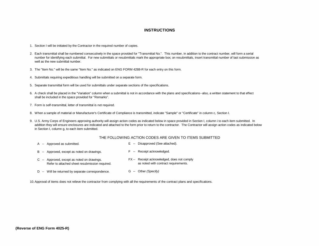
INSTRUCTIONS
1. Section I will be initiated by the Contractor in the required number of copies.
2. Each transmittal shall be numbered consecutively in the space provided for "Transmittal No.". This number, in addition to the contract number, will form a serialnumber for identifying each submittal. For new submittals or resubmittals mark the appropriate box; on resubmittals, insert transmittal number of last submission aswell as the new submittal number.
3. The "Item No." will be the same "Item No." as indicated on ENG FORM 4288-R for each entry on this form.
4. Submittals requiring expeditious handling will be submitted on a separate form.
5. Separate transmittal form will be used for submittals under separate sections of the specifications.
6. A check shall be placed in the "Variation" column when a submittal is not in accordance with the plans and specifications--also, a written statement to that effectshall be included in the space provided for "Remarks".
7. Form is self-transmittal, letter of transmittal is not required.
8. When a sample of material or Manufacturer's Certificate of Compliance is transmitted, indicate "Sample" or "Certificate" in column c, Section I.
9. U.S. Army Corps of Engineers approving authority will assign action codes as indicated below in space provided in Section I, column i to each item submitted. Inaddition they will ensure enclosures are indicated and attached to the form prior to return to the contractor. The Contractor will assign action codes as indicated belowin Section I, column g, to each item submitted.
THE FOLLOWING ACTION CODES ARE GIVEN TO ITEMS SUBMITTED
A -- Approved as submitted.
B -- Approved, except as noted on drawings.
C -- Approved, except as noted on drawings.Refer to attached sheet resubmission required.
D -- Will be returned by separate correspondence.
10.Approval of items does not relieve the contractor from complying with all the requirements of the contract plans and specifications.
(Reverse of ENG Form 4025-R)
E -- Disapproved (See attached).
F -- Receipt acknowledged.
FX -- Receipt acknowledged, does not complyas noted with contract requirements.
G -- Other (Specify)

CONTRACT NO. W912P8-09-B-0035SPECIFICATION NO. 01330
DATA
DRAWINGS
INSTRUCTIONS
SCHEDULES
STATEMENTS
REPORTS
CERTIFICATES
SAMPLES
RECORDS
INFORMATION
ONLY
GOVERNMENT
APPROVED
SUBMIT
APPROVAL
NEEDED BY
MATERIAL
NEEDED BY
CODE
DATE
SUBMIT TO
GOVERNMENT
CODE
DATE
REMARKS
a b c d e f g h i j k l m n o p q r s t u v w x y z1 01100-3.b Accident Prevention Program x x x x x2 01100-3.c Hazard Communication Program x x x x3 01100-20 Access Plan x x4 01321-1.5 Construction Schedule x5 01331-1.3 Survey Data x x x x x x ED-T6 01352-1.4.1 Environmental Pollution Control Plan x x x x7 01352-3.3 Endangered Species Protection x x x8 01451-3.2.1 Quality Control Plan x x9 02231-1.2 QC Reports x x x x x x x
10 02245-1.3.1.1 Geotextiles x x11 02382-1.4.3 Articulated Concrete Block x x x12 02930-2.1 Plants x x x x x x1314151617
PROPONENT (CEMP-CE)
NOTE: THIS REGISTER IS NOT NECESSARILY COMPLETE. THE CONTRACTOR SHALL BE RESPONSIBLE FOR DEVELOPING A COMPREHENSIVE REGISTER
PAGE 1 OF 1
TYPE OF SUBMITTALS CLASS-IFICATION
REVIEWER
CONTRACTOR'SSCHEDULE DATES
CONTRACTORACTION
ENG FORM 4288-R
GOVERNMENTACTION
SUBMITTAL REGISTER(ER 415-1-10)
TITLE AND LOCATIONGrand Isle and Vicinity, Hurrican Protection Project, Rehabiliation of Hurricane Gustav and Hurricane Ike Damage - 2009, Jeffereson Parish, LA
CONTRACTOR
ACTIVITY NO
TRANSMITTAL NO
ITEM NO
SPECIFICATION
PARAGRAPH NO
DESCRIPTION OF
ITEM SUBMITTED
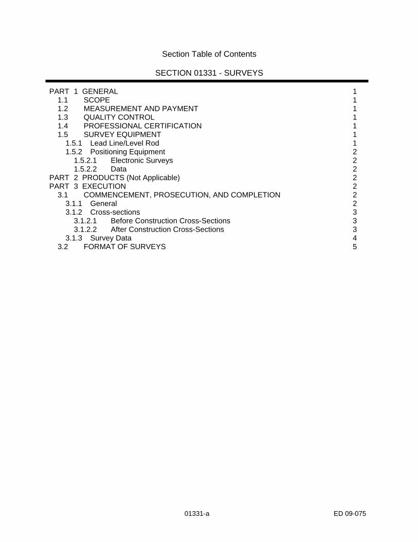
Section Table of Contents
SECTION 01331 - SURVEYS PART 1 GENERAL 1
1.1 SCOPE 1 1.2 MEASUREMENT AND PAYMENT 1 1.3 QUALITY CONTROL 1 1.4 PROFESSIONAL CERTIFICATION 1 1.5 SURVEY EQUIPMENT 1
1.5.1 Lead Line/Level Rod 1 1.5.2 Positioning Equipment 2
1.5.2.1 Electronic Surveys 2 1.5.2.2 Data 2
PART 2 PRODUCTS (Not Applicable) 2 PART 3 EXECUTION 2
3.1 COMMENCEMENT, PROSECUTION, AND COMPLETION 2 3.1.1 General 2 3.1.2 Cross-sections 3
3.1.2.1 Before Construction Cross-Sections 3 3.1.2.2 After Construction Cross-Sections 3
3.1.3 Survey Data 4 3.2 FORMAT OF SURVEYS 5
01331-a ED 09-075

SECTION 01331 - SURVEYS PART 1 GENERAL 1.1 SCOPE
The work provided for herein consists of furnishing all plant, labor, equipment, and materials, and performing all operations necessary for surveying as specified herein and as indicated on the contract drawings.
1.2 MEASUREMENT AND PAYMENT
No separate measurement or payment will be made for surveys. 1.3 QUALITY CONTROL
The Contractor shall establish and maintain quality control for the work specified in this section to assure compliance with the contract requirements and maintain records of his quality control for all surveying including but not limited to the following: (1) Layouts and Surveys. Daily log of layout work and surveys consisting of type and location using the Government furnished conventional land baseline monumentation as stated in the Contract Clause in Section 00700, entitled "Layout of Work (FAR 52.236-17)". (2) Reporting. The original and two copies of these reports and tests, as well as the records of corrective action taken, shall be furnished the Government daily. The report shall include a record of times and dates surveys were run, the horizontal control stations used and their coordinates, the vertical control points used and their elevations, and weather conditions. Format of report shall be as prescribed in Section 01451, "CONTRACTOR QUALITY CONTROL".
1.4 PROFESSIONAL CERTIFICATION
All surveys shall be performed in the presence of the Contracting Officer's Representative. All surveys shall be performed under the direction of and certified by a Professional Land Surveyor currently licensed by a state of the United States and familiar with the USACE Hydrographic Surveying Engineering Manual, EM 1110-2-1003, and procedures therein.
1.5 SURVEY EQUIPMENT 1.5.1 Lead Line/Level Rod
Lead lines used for soundings shall consist of a 12-pound lead having a 6-inch mushroom-shaped bottom. Level rods if used for soundings shall have a 6-inch
01331-1 ED 09-075
square plate attached to the bottom, unless otherwise directed by the Government Inspector.
1.5.2 Positioning Equipment 1.5.2.1 Electronic Surveys
Positioning equipment for electronic surveys shall be capable of achieving the required accuracy for the project. Initial calibration and subsequent checks shall be in accordance with the manufacturer's instructions as required in paragraph 3.1.1.
1.5.2.2 Data
The Contractor shall furnish the required data on IBM compatible CD-ROM containing ASCII character set. The information received should be free of errors and in the following format: (a) The X-coordinate in feet of a recognized Louisiana Lambert grid system, (b) the Y-coordinate in feet of same recognized Louisiana grid system, (c) the elevation in feet of NAVD88, and (d) remarks such as the station number (i.e. 1+00), CL (for centerline), ES (for end of station), EJ (for end of file), and direction of survey (either “L” for + or “R” for -, followed by Station No., i.e. L 30+00). The time and date the cross section was taken and the gage reading applicable to the section shall also be included. The electronic data files, along with a hard copy, shall be presented to the Government Representative on site no later than 3 days after the survey is taken. Under no circumstances shall the information be edited for the purpose of eliminating incorrect soundings. The Contractor shall provide a separate file listing all incorrect soundings to be eliminated. Additional format requirements for these files will be discussed, and sample formatted files will be made available, at the pre-work coordination meeting. The beginning station for each file shall be the repeated ending station from the previous file (i.e., Sta. 820+00 to 840+00, Sta. 840+00 to 860+00, etc.). The format for survey file(s) to be submitted to the Government will be discussed and sample sheets will be given at the Pre-work Coordination Meeting.
PART 2 PRODUCTS (Not Applicable) PART 3 EXECUTION 3.1 COMMENCEMENT, PROSECUTION, AND COMPLETION 3.1.1 General
Surveys for all fixed stations shall be performed in accordance with Class 1 Third Order accuracy as defined by the National Oceanic and Atmospheric administration in "Classification, Standards of Accuracy, and General Specifications of Geodetic Control Surveys." Prior to initiating positioning surveys using electronic survey equipment, a calibration test of the electronic measuring device shall be performed according to the manufacturer's instructions in the presence of the government
01331-2 ED 09-075

inspector. Calibration checks shall be run at the beginning and completion of each day's survey or portion thereof. The government inspector must witness and approve, via signature, each calibration check. Results shall be furnished daily to the government inspector. All electronic surveys shall be tied to one or more of the secondary control points established by the Government as benchmarks labeled or other benchmarks approved by the Contracting Officer. Should the electronic measuring device fail to indicate the known distance within the factory defined error range for the device; the device shall not be used for determining survey positions.
3.1.2 Cross-sections 3.1.2.1 Before Construction Cross-Sections (1) Sand Dune and Beach
The Contractor shall use the government furnished dune survey as the “Before Construction Cross-Sections”. The Contractor shall provide original cross sections of the beach to the Government. These original cross sections of the beach will be used along with the final compliance surveys to figure quantity.
3.1.2.2 After Construction Cross-Sections
(1) Geotextile Tube The Contractor shall take a centerline survey of the top of the geotextile tube structure to ensure compliance with government specifications. Upon completion of suitable reaches of geotextile tube construction, the Contractor shall perform, plot, and submit a geotextile tube centerline profile with shots taken at a maximum of 25-foot intervals. (2) Sand Dune (a) Compliance Surveys. The Contractor shall furnish plotted cross sections at intervals and locations corresponding to the Government's original survey. Upon completion of suitable reaches of embankment, the Contractor shall perform, plot and submit compliance cross section surveys at a maximum of 500-foot intervals and all P.I.'s, dune transitions and breakpoints. All sections shall be taken at locations corresponding to the Government original survey. They shall be plotted by the Contractor on a minimum scale of 1-inch equals 50 feet horizontally and 1 inch equals 5 feet vertically with the theoretical design cross section and allowable grade tolerances superimposed thereon. Additionally, the Contractor shall perform, plot, and submit a dune centerline profile with shots taken at a maximum of 25-foot intervals. (b) Quantity Surveys. The Contractor shall provide plotted cross sections of all surveys for progress payments at a maximum of 500-foot intervals. Perform, plot and
01331-3 ED 09-075

submit partial levee cross sections at a maximum of 500-foot intervals for determining progress payments. Plot on the same scale noted above. (3) Beach (a) Compliance Surveys. The Contractor shall furnish plotted cross sections at intervals and locations corresponding to the original survey. Upon completion of suitable reaches of beach, the Contractor shall perform, plot and submit compliance cross section surveys at a maximum of 500-foot intervals. All sections shall be taken at locations corresponding to the Contractors original survey. They shall be plotted by the Contractor on a minimum scale of 1-inch equals 50 feet horizontally and 1 inch equals 5 feet vertically with the theoretical design cross section and allowable grade tolerances superimposed thereon. (b) Quantity Surveys. The Contractor shall provide plotted cross sections of all surveys for progress payments at a maximum of 500-foot intervals. Perform, plot and submit partial beach cross sections at a maximum of 500-foot intervals for determining progress payments. Plot on the same scale noted above.
3.1.3 Survey Data
Each field book shall be given an identification number, which shall be noted on each page of the book. The information shown in the field notes shall meet the requirements of the Contracting Officer's Representative. If a total station instrument is used to perform the survey, the Contractor shall submit a copy of the survey data on magnetic media, print out of the survey data, and computer-plotted profiles and cross-sections from the original data. The Contractor shall promptly plot the before construction cross-sections on a scale of 1 inch = 50 feet horizontally and 1 inch = 2 feet vertically, or to a scale agreeable to the Contracting Officer’s Representative. Plotted cross-sections, profiles, and duplicate notes shall be kept at the jobsite at all times and made available to the Contracting Officer's Representative as required. The contractor shall furnish to the Contracting Officer's Representative the plotted original cross-sections for a minimum distance of 1000 feet ahead of foreshore dike construction. The original field book and notes shall be submitted to the Contracting Officer’s Representative within 3 days of the completion of surveys. Offshore Borrow Area: The contractor shall perform pre-dredging surveys of the borrow area. The pre-dredging surveys shall be comprised of cross-section surveys performed over the entire length and width of the borrow area with survey lines spaced at 250-ft parallel to the long side of the dredge borrow area. The contractor shall perform, plot and submit both hard copy and electronic versions of the surveys overlaid on project plan sheet page C-8. Within 10 days of completing dredging operations in the borrow area a post-dredging survey shall be performed over the identical cross section survey grid. The post dredging survey also should be plotted overlaid on project plan sheet page-8. Both a hard copy and electronic version of the post-dredging survey should be submitted.
01331-4 ED 09-075

01331-5 ED 09-075
3.2 FORMAT OF SURVEYS
The Contractor shall submit a survey upon completion of all construction activities. The survey shall be in USACE EM Format as described in Section H of the “USACE New Orleans District Guide for Minimum Survey Standards”. This document can be found at the following location: http://www.mvn.usace.army.mil/ed/edss/USACE_MVN_Min_Survey_Standards.PDF. Each surveyed point should be listed on a separate line as a comma-delimited list of the following:
(1) Point_id, northing, easting, elevation, code (2) Surveyed points that are part of a profile shall be grouped under the appropriate #P01 record for that profile. (3) Surveyed points that are part of a cross-section shall be grouped under the appropriate #X01 record for that cross-section. (4) All other points shall be grouped under the appropriate #M01 record.
The code value shall be one of the three letter codes listed in Appendix 2 of “USACE New Orleans District Guide for Minimum Survey Standards”. If a surveyed point is not one of the items listed in Appendix 2, the Contractor should submit a CODES.DAT file containing a semi-colon delimited list of these unique survey codes. Each reference benchmark should be included as #V/#T records with the surveyed elevation #V/T06, and vertical datum and epoch information. The point of contact for survey information is Ronald King @ 504.862.1853. A sample EM Format file is attached at the end of this section.


#H01 SAMPLE.EM #H02 11/06/06 #H03 3 #H04 NAD83 #H05 07-002 #H06 FT #H07 1702 #H08 PLAQUEMINES PARISH LA #H09 CHUSTZ SURVEYING INC. #H12 1.0 #H13 PLAQUEMINES PARISH #H14 NEW ORLEANS EAST SE CHALMETTE SW BERTRANDVILLE NE & NW #H15 W912P8-06-D-0050 #H20 WEST BANK & VICINITY ALGIERS CANAL HURRICANE PROTECTION #H21 LEVEES HERO TO BELLE CHASSE HWY (EAST SIDE) & BELLE CHASSE #H22 HWY TO ALGIERS LOCK (WEST SIDE) ; ; ;-------------------VERTICAL CONTROL INFORMATION--------------------- ; ; #V01 BEL 1 #V02 -3.42 #V03 2004.65 #V04 NAVD88 #V05 GOOD #V06 -3.42 #V07 494282.40,3697937.71 #V20 MONUMENT IS A 3/4" IRON ROD SET FLUSH WITH THE GROUND. IT IS #V21 LOCATED 5.9 FT SE OF A RAILROAD IRON 25 FT NE OF ANOTHER #V22 RAILROAD IRON AND 116 FT EAST OF A GATE POST AT THE PUMP #V23 STATION AREA. #V24 PROJECT BENCHMARK POINTS ARE BEL1 AND V375 SEE #V25 GPS REPORT FOR DETAILS. ; ; #V01 770+58.11 (SETTLEMENT PLUG) #V02 19.21 #V03 2004.65 #V04 NAVD88 #V05 GOOD #V06 19.21 #V07 516940.13,3711674.20 #V20 MONUMENT IS A SETTLEMENT PLUG IN CONCRETE. IT IS LOCATED 9.4 FT #V21 EAST NE OF THE EAST EDGE OF THE METAL STEPS 13.55 FT NE OF THE #V22 EAST CORNER OF THE LOCK WALL AND 17.3 FT NW OF THE NE CORNER #V23 OF THE LOCK HOUSE. ; ; ;-------------------TEMPORARY BENCHMARK INFORMATION------------------ ; ; #T01 TBM AC-1 #T02 7.96 #T05 GOOD #T06 7.96 #T10 MONUMENT IS A STANDARD COE BRASS CAP RECESSED 0.5' BELOW GROUND

#T11 STAMPED "AC-1 07002C". IT IS LOCATED +/-500 FT. SW OF THE #T12 CONCRETE BRIDGE OVER THE CANAL AT GENERAL DE GAULLE RD 69.3 FT #T13 NW OF THE WATERS EDGE OF THE CANAL 17.6 FT NE OF THE SOUTHERN #T14 GATE POST OF AN ENTRANCE GATE AND 17.8 FT NE OF THR NORTHERN #T15 MOST GATE POST. ; ; #T01 TBM AC-2 #T02 8.50 #T05 GOOD #T06 8.50 #T07 482914.44,3683055.07 #T10 MONUMENT IS A STANDARD COE BRASS CAP ON REBAR STAMPED "AC2 #T11 07002C". IT IS LOCATED 86.4 FT WNW OF THE AIRBASE FENCELINE #T12 1.6 MILES SW OF THE PUMP STATION AT THE CROSSING AND 0.17 #T13 MILES NE OF THE EDGE OF THE ASPHALT ROAD AT THE AIRBASE BOAT #T14 RAMP. ; ; #T01 TBM AC-3 #T02 8.86 #T05 GOOD #T06 8.86 #T07 482917.55,3683035.15 #T10 MONUMENT IS A STANDARD COE BRASS CAP ON REBAR STAMPED "AC3 #T11 07002C". IT IS LOCATED 334 FT NW OF THE NORTHERNMOST GATE POST #T12 ON THE ENTRANCE GATE TO THE LEVEE 336 FT NNW OF THE SOUTHERN #T13 POST 0.2 MILES SE OF A POWER LINE CROSSING AND 1 MILE SE OF #T14 A CHAIN LINE FENCE GATE CROSSING THE LEVEE. ; ; ; ; #H02 11/06/06 ; ; #H10 070003 #H11 53 ; ; ; ; ;------------------------FIELD PERSONNEL---------------------------- ; #C01 J. GREMILLION #C02 J. MASSE #C03 K. MANUEL #C03 S. HOLMES ; ;---------------------------EQUIPMENT-------------------------------- ; #E01 TOTAL STATION #E02 46587793 #E03 TCR-305 ; #E01 LEICA #E02 235668975

#E03 GT-3 ; ;-------------------------------------------------------------------- ; #H02 11/02/06 ; ; #H10 070003 #H11 19 ; ; ;-----------------------GAGE INFORMATION-------------------------- ; ; #G02 GAGE AC-3 #G03 0.50 #G04 12:55 #G07 483479.75,3683384.21 #G10 TEMPORARY STAKE GAGE SET AT AC-3 ; ; ;---------------------- CROSS-SECTION ----------------------------- ; ; #X01 3700241.41 501025.16 3700687.38 500799.09 57090.00 570+90 #X03 10:53 #X04 0.80 20590,500960.30,3700343.72,-11.10,SND 20591,500954.99,3700362.88,-13.30,SND 20592,500948.11,3700381.50,-16.50,SND 20593,500942.69,3700401.47,-16.80,SND 20594,500934.73,3700420.93,-18.20,SND 20595,500927.26,3700438.51,-17.00,SND 20596,500916.38,3700455.22,-13.30,SND 20597,500907.08,3700473.36,-10.90,SND 20598,500899.57,3700491.79,-8.50,SND 20599,500892.12,3700510.12,-5.40,SND 20600,500882.66,3700528.07,-4.90,SND 20601,500872.68,3700545.22,-4.50,SND 20602,500862.95,3700562.58,-1.70,SND 20603,500854.68,3700581.17,-1.55,SND 20604,500847.27,3700599.48,-1.88,SND 20605,500838.98,3700617.69,-0.74,SND 20606,500830.68,3700635.90,0.40,SND ; ;----------------------- PROFILE --------------------------------------- #P01 5552,494333.46,3697419.77,9.27,SHP 5553,494376.90,3697443.90,8.56,SHP 5554,494398.99,3697455.69,8.36,SHP 5555,494410.50,3697455.82,8.24,SHP 5556,494411.15,3697455.40,7.78,CLL 5557,494419.34,3697455.62,8.17,CLL 5558,494428.02,3697458.04,8.15,CLL 5559,494439.50,3697463.11,8.46,CLL 5560,494483.81,3697485.83,8.43,CLL 5561,494524.13,3697505.97,8.66,CLL

5562,494550.34,3697518.80,8.54,CLL 5563,494585.08,3697537.20,8.66,CLL 5564,494625.86,3697557.24,8.70,CLL 5565,494664.84,3697577.20,8.93,CLL 5566,494704.71,3697597.16,8.94,CLL 5567,494743.17,3697617.15,8.82,CLL 5568,494782.44,3697636.60,8.64,CLL 5569,494823.03,3697657.00,8.69,CLL 5570,494861.50,3697676.57,8.56,CLL 5571,494898.96,3697696.31,8.77,CLL 5572,494921.54,3697707.77,6.95,CLL 5573,494932.32,3697709.54,7.94,SHP 5574,494950.46,3697718.64,7.67,SHP 5575,494956.49,3697722.33,7.35,SHP 5576,494957.71,3697722.81,6.43,CLL 5577,494971.83,3697731.26,5.79,CLL 5578,494987.62,3697740.41,5.77,CLL 5579,495001.65,3697748.14,5.33,ESH 5580,495024.72,3697759.96,5.43,ESH 5581,495029.15,3697761.70,5.74,CLL ; ;--------------- MISC. SHOT POINTS --------------------------- #M01 MISCELLANEOUS SHOTS TAKEN IN BETWEEN RANGES 312+00 AND 318+00 ; ; 2807,482976.57,3682869.45,1.52,FL 2808,482905.77,3682933.86,4.69,FL 2809,482896.57,3682942.44,9.02,FL 2810,482885.94,3682951.60,8.64,FL 2811,482863.67,3682971.79,-0.26,FL 2812,482785.09,3683042.12,-2.88,FL 2813,482917.55,3683035.15,-0.89,RMP 2814,482931.41,3683036.73,1.15,RMP 2815,482952.25,3683037.10,4.61,RMP 2816,482977.95,3683039.14,8.61,RMP 2817,482998.08,3683041.58,9.32,RMP 2818,483030.60,3683049.20,7.53,RMP 2819,483056.35,3683056.21,4.64,RMP 2820,483051.39,3683065.63,5.47,RMP 2821,483033.83,3683062.95,7.85,RMP 2822,483020.70,3683060.67,9.36,RMP 2823,482995.31,3683055.36,9.26,RMP 2824,482970.99,3683049.58,7.08,RMP 2825,482951.69,3683049.63,4.06,RMP 2826,482914.44,3683055.07,-1.17,RMP 2827,483110.59,3683031.57,2.16,PIR 2828,483127.39,3683017.25,2.61,PIR 2829,483137.72,3683029.53,2.55,PIR 2830,483133.88,3683032.85,2.46,PIR 2831,483125.12,3683022.40,2.67,PIR 2832,483112.12,3683033.44,2.18,PIR 2833,483265.05,3683138.27,1.66,FL 2834,483195.48,3683208.46,5.46,FL 2835,483183.05,3683219.30,9.36,FL 2836,483172.83,3683229.40,9.28,FL 2837,483156.14,3683245.27,1.95,FL 2838,483069.19,3683323.97,-3.40,FL

Section Table of Contents
SECTION 01352 – ENVIRONMENTAL PROTECTION PART 1 GENERAL 1
1.1 SCOPE 1 1.2 APPLICABLE REGULATIONS 1 1.3 MEASUREMENT AND PAYMENT 2
1.3.1 Environment Protection 2 1.3.2 Non-Regulated Waste 2 1.3.3 Hazardous/Regulated Waste 2
1.4 QUALITY CONTROL 2 1.4.1 General 2 1.4.2 Reporting 3
1.5 NOTIFICATION 3 1.6 SUBCONTRACTORS 3 1.7 IMPLEMENTATION 3
1.7.1 Environmental Assessment of Contract Deviations 4 PART 2 PRODUCTS (NOT APPLICABLE) 4 PART 3 EXECUTION 4
3.1 PROTECTION OF LAND RESOURCES 4 3.1.1 General 4 3.1.2 Prevention of Landscape Defacement 5 3.1.3 Temporary Excavation and Embankments 5 3.1.4 Post-Construction Cleanup or Obliteration 6 3.1.5 Recording and Preserving Historical and Archeological Finds 6
3.2 PROTECTION OF WATER RESOURCES 6 3.2.1 Contamination of Water 6 3.2.2 Disposal of Materials 6 3.2.3 Erosion Control 6
3.3 PROTECTION OF FISH AND WILDLIFE 7 3.3.1 Manatees 7
3.3.1.1 Manatee Signs 8 3.3.1.2 Sightings 8
3.4. JANITOR SERVICES 8 3.5 DISPOSAL OF NON-REGULATED DEBRIS AND OTHER WASTE 9 3.6 DISPOSAL OF HAZARDOUS AND/OR REGULATED SOLID WASTES 9
3.6.1 Hazardous Wastes 10 3.6.2 Regulated Solid Wastes 10 3.6.3 Laboratory Accreditation 11
3.7 MAINTENANCE OF POLLUTION CONTROL FACILITIES 11 3.8 REPORTING OF POLLUTION SPILLS 11
01352-a ED 09-075

SECTION 01352 - ENVIRONMENTAL PROTECTION PART 1 GENERAL 1.1 SCOPE
The work covered by this section consists of furnishing all labor, materials and equipment, and performing all work required for the prevention of environmental pollution and the handling, removal, transportation and disposal of any hazardous and/or regulated solid waste generated during and as the result of construction operations under this contract except for those measures set forth in other provisions of these specifications. For the purpose of this specification, environmental pollution is defined as the presence of chemical, physical, or biological elements or agents which adversely affect human health or welfare; unfavorably alter ecological balances of importance to man; or degrade the utility of the environment for esthetic and recreational purposes. The control of environmental pollution requires consideration of air, water, and land, and involves noise, solid waste-management, management of radiant energy and radioactive materials, as well as other pollutants including hazardous wastes, materials, substances and chemicals.
1.2 APPLICABLE REGULATIONS
In order to prevent, and to provide for abatement and control of any environmental pollution arising from construction activities in the performance of this contract, the Contractor shall comply with all applicable Federal, State, and Local laws, and regulations as well as USACE regulations concerning environmental pollution control and abatement and any regulations referred to in the following paragraphs. For hazardous wastes, materials, substances and chemicals applicable regulations shall include, but are not limited to: USACE EM 385-1-1, Louisiana Administrative Code (LAC), Title 33, Environmental Quality, Part V, Hazardous Waste and Hazardous Materials, and LAC Title 33, Environmental Quality, Part VII, Solid Waste Regulations, 29 CFR 1910 Occupational Safety and Health Standards, 29 CFR 1910.1200 Hazard Communication 40 CFR 260 Hazardous Waste Management Systems: General, 40 CFR 261 Identification and Listing of Hazardous Waste, 40 CFR 262 Generators of Hazardous Waste, 40 CFR 263 Transporters of Hazardous Waste, 40 CFR 264 Owners and Operators of Hazardous Waste, Treatment, Storage, and Disposal Facilities, 40 CFR 265 Interim Status Standard for Owners and Operators of Hazardous Waste Treatment, Storage, and Disposal Facilities, 40 CFR 266 Management of Specific Hazardous Wastes and Specific Types of Hazardous Waste Management Facilities, 40 CFR 268 Land Disposal Restrictions, 40 CFR 279 Standards for the Management of Used Oil, 40 CFR 355 Emergency Planning and Notification, 40CFR 372 Toxic Chemical Release Reporting Community Right To Know, 49 CFR 171-178 Hazardous Materials Requirements.
01352-1 ED 09-075

1.3 MEASUREMENT AND PAYMENT 1.3.1 Environment Protection
No separate measurement or payment will be made for environmental protection including protection of fish and wildlife. Payment for the work covered under this section unless otherwise specified shall be distributed throughout the existing bid items.
1.3.2 Non-Regulated Waste
No separate measurement or payment will be made for the work associated with and the disposal of non-regulated debris not specifically covered elsewhere. Payment for the work associated with and the disposal of non-regulated debris not specifically covered elsewhere shall be distributed throughout the existing bid items.
1.3.3 Hazardous/Regulated Waste
If the Contractor generates hazardous and/or regulated solid wastes through his/her actions, no separate measurement or payment will be made for handling, removal, transportation and disposal of hazardous and/or regulated solid wastes. Payment for the work associated with and the disposal of hazardous/regulated solid waste generated by the Contractor shall be distributed throughout the existing bid items. If the Contractor uncovers an existing hazardous/regulated waste not Contractor generated, not shown on the drawings, and not specified herein, the Contractor must notify the COR immediately. Payment for handling, removal, transportation and disposal of hazardous and/or regulated solid wastes not Contractor generated, not shown on the drawings, and not specified herein will be made as an equitable adjustment in contract price under the Contract Clause in Section 00700, entitled Changes (FAR 52.243-4).
1.4 QUALITY CONTROL 1.4.1 General
The Contractor shall establish and maintain quality control for environment protection to assure compliance with contract specifications and maintain records of his quality control for all construction operations including but not limited to the following: (1) Submit Environmental Pollution Plan/Environmental Protection Plan. For Contractor work activities (such as capping piles, field treating damaged piles, etc.) that will involve bringing hazardous chemicals, hazardous substances or hazardous materials onto the project site, the Contractor shall include in the plan a Hazard Communication Program and Safe Storage Plan. For Contractor activities that anticipate generation of hazardous wastes at the project site, the Contractor shall
01352-2 ED 09-075

include in the plan a Waste Identification / Determination and Waste Disposal Plan. For Contractor on-site activities that pose a risk of an oil or hazardous substance spill, the Contractor shall include in the plan a Spill Reporting and Response Plan. (2) Procure applicable Federal, State, and Local regulations on pollution control. (3) Air Pollution - Checks made on dust, smoke, and noise. (4) Water Pollution - Checks made on disposal of water, oil, etc. (5) Land Pollution - Checks made on disposal of debris, restoration of temporary construction sites, etc. (6) Training Course for Employees.
1.4.2 Reporting
The original and two copies of these records, as well as the records of corrective action taken, shall be furnished the Government daily. Format of report shall be as prescribed in Section 01451, "CONTRACTOR QUALITY CONTROL".
1.5 NOTIFICATION
The Contracting Officer will notify the Contractor in writing of any non-compliance with the foregoing provisions and the action to be taken. The Contractor shall, after receipt of such notice, immediately take corrective action. Such notice, when delivered to the Contractor or his/her authorized representative at the site of the work, shall be deemed sufficient for the purpose. If the Contractor fails or refuses to comply promptly, the Contracting Officer may issue an order stopping all or part of the work until satisfactory corrective action has been taken. No part of the time lost due to any such stop orders shall be made the subject of a claim for extension of time or for excess cost of damages by the Contractor.
1.6 SUBCONTRACTORS
Compliance with the provisions of this section by subcontractors will be the responsibility of the Contractor.
1.7 IMPLEMENTATION
Within 10 days after receipt of Notice of Award, or otherwise directed below, the Contractor shall: (1) Submit in writing his/her proposals for implementing environmental pollution control at the project site, disposal of debris, non-hazardous wastes and hazardous wastes generated at the project site as well as storage and management of regulated
01352-3 ED 09-075

materials, substances and chemicals brought onto and used at the project site. Provide one copy each to the Contracting Officer and one copy to CEMVN-PM-RS; Attention Beth Nord for review prior to approval of the document by the Contracting Officer. (2) Meet with representatives of the Contracting Officer to develop mutual understanding relative to compliance with this provision and administration of the environmental pollution control program. (3) If applicable, submit a plan for the identification, handling, removal, transportation and disposal of hazardous and/or regulated solid wastes generated because of the Contractor's operation.
1.7.1 Environmental Assessment of Contract Deviations
The Contractor is advised that deviations from the drawings or specifications (e.g., proposed alternate borrow areas, disposal areas, staging areas, alternate access routes, etc.) could result in the requirement for the Government to reanalyze the project from an environmental standpoint. Deviations from the construction methods and procedures indicated by the plans and specifications, which may have an environmental impact, will require an extended review, processing, and approval time by the Government. The Contracting Officer reserves the right to disapprove alternate methods, even if they are more cost effective, if the Contracting Officer determines that the proposed alternate method will have an adverse environmental impact.
PART 2 PRODUCTS (NOT APPLICABLE) PART 3 EXECUTION 3.1 PROTECTION OF LAND RESOURCES 3.1.1 General
The land resources within the project boundaries and outside the limits of permanent work performed under this contract shall be preserved in their present condition or be restored to a condition after completion of construction that will appear to be natural and not detract from the appearance of the project. The Contractor shall confine his/her construction activities to areas defined by the plans or specifications. The following additional requirements are intended to supplement and clarify the requirements of the Contract Clauses in Section 00700, entitled Cleaning Up (FAR 52.236-12), Protection Of Existing Vegetation, Structures, Equipment, Utilities, And Improvements (FAR 52.236-9), and Operations And Storage Areas (FAR 52.236-10).
01352-4 ED 09-075
3.1.2 Prevention of Landscape Defacement
Except in areas to be cleared and as provided in paragraph 3.1.3, the Contractor shall not deface, injure, or destroy trees or shrubs, nor remove or cut them without the approval of the Contracting Officer. Felling of trees shall be performed in such a manner as to avoid damage to trees to be left standing. Where trees may possibly be defaced, bruised, injured, or otherwise damaged by the Contractor's operations or equipment; adequate protection measures shall be implemented. A tree protection zone shall be constructed around all trees that may be affected by construction activities. The tree protection zone shall be established by placing metal posts and temporary construction safety fencing around trees below the trees’ canopy drip edge. The Contractor shall not store any material, equipment, backfill, drive any machinery, or cause any changes to the existing grade around trees and their respective canopy drip edges. Native material shall not be displaced into uncleared areas. All excess native material shall be removed from the construction site. All monuments and markers shall be protected before beginning operations near them, or properly removed and stored by the Contractor during construction, and repositioned after construction. Landscape features damaged by the Contractor's equipment or operations shall be replaced or restored to their original condition. The Contractor shall secure the services of a licensed arborist to assess any damage to trees that occur as a result of construction activities. The Contractor shall submit to the Contracting Officer, for review and approval, a written report from the licensed arborist on the inflicted damage, as well as a proposed remediation plan of action, or if required the replacement of affected trees. The plan of action shall identify measures such as proper pruning and bark tracing to restore the damaged trees, or tree replacement options. No separate measurement and payment will be made for all work required to implement tree protection zone measures around all trees within the construction limits that are to remain. The Contractor shall include any and all costs for tree protection zone measures in the contract prices for items to which the work is incidental thereto. Should the services of a licensed arborist be required as a result of damages due to the actions of the Contractor, all services, material, labor and equipment to implement the remediation plan and restore and or replace the affected trees shall be accomplished by the Contractor at no additional cost to the Government.
3.1.3 Temporary Excavation and Embankments
If the Contractor proposes to construct temporary roads or embankments and excavation for plant and/or work areas, the Contractor shall obtain approval of the Contracting Officer prior to start of such temporary work. Reference Section 01100; Rights-of-way regarding possible environmental requirements associated with deviations from Government furnished rights-of-way.
01352-5 ED 09-075

3.1.4 Post-Construction Cleanup or Obliteration
The Contractor shall obliterate all signs of temporary construction facilities such as haul roads, work areas, structures, foundations of temporary structures, and stockpiles of excess or waste materials upon completion of construction. The Contractor will be required to restore the construction area to near natural conditions which will permit the growth of vegetation.
3.1.5 Recording and Preserving Historical and Archeological Finds
When any item having apparent historical or archaeological interest is discovered in the course of any construction activities, then no work will proceed in the area containing these cultural resources until a USACE archaeologist has been notified and final coordination with the State Historic Preservation Officer has been completed. The contractor shall leave the archaeological find undisturbed and shall immediately report the find to the Contracting Officer so that the proper authorities may be notified.
3.2 PROTECTION OF WATER RESOURCES 3.2.1 Contamination of Water
The Contractor shall not pollute lakes, ditches, rivers, bayous, canals, groundwater, waterways, or reservoirs with fuels, oils, bitumens, calcium chloride, insecticides, herbicides, or other similar materials harmful to fish, shellfish, or wildlife, or materials which may be a detriment to outdoor recreation.
3.2.2 Disposal of Materials
The methods and locations of disposal of materials, wastes, effluents, trash, garbage, oil, grease, chemicals, etc., within the right-of-way limits shall be such that harmful debris will not enter lakes, ditches, rivers, bayous, canals, groundwater, waterways, or reservoirs by erosion, and thus prevent the use of the area for recreation or present a hazard to wildlife.
3.2.3 Erosion Control
Surface drainage from cuts and fills within the construction limits, whether or not completed, and from borrow and waste disposal areas, shall, if turbidity producing materials are present, be held in suitable sedimentation ponds or shall be graded to control erosion within acceptable limits. Temporary erosion and sediment control measures such as berms, dikes, drains, hay bales, erosion control fences or curtains, or sedimentation basins, if required to meet the above standards, shall be provided and maintained until permanent drainage and erosion control facilities are completed and operative. The area of bare soil exposed at any one time by construction operations shall not exceed that necessary to perform the work. Stream crossings by
01352-6 ED 09-075
fording with equipment shall be limited to control turbidity and in areas of frequent crossings temporary culverts or bridges shall be installed. Any temporary culverts or bridges shall be removed upon completion of the project. Fills and waste area shall be constructed by selective placement to eliminate silts or clays on the surface that will erode and contaminate adjacent streams.
3.3 PROTECTION OF FISH AND WILDLIFE
The Contractor shall at all times perform all work and take such steps required to prevent any interference of disturbance to fish and wildlife. The Contractor will not be permitted to alter water flows or otherwise disturb native habitat adjacent to the project area, which are critical to fish or wildlife. Colonial nesting wading birds (including, but not limited to herons, egrets, and ibis) and seabirds/waterbirds (including, but not limited to, terns, gulls, black skimmers, and pelicans) should be avoided to reduce the risk of injuring birds. The nesting activity period generally extends from February 15 through September 15. Presence of nesting wading birds and/or seabirds/waterbirds must be immediately reported to Beth Nord at (504)862-2167. If nests of these birds are present on the work area, a no-work distance restriction of 650 feet for terns, gulls, and black skimmers, 1000 feet for colonial nesting wading birds, and 2000 feet for brown pelicans must be implemented. Coordination by New Orleans District personnel with the U.S. Fish and Wildlife Service may result in a reduction of no-work distance restrictions depending on the species of birds found nesting at the work site. The contractor should note that the only federally listed birds that would occur in the project area are the brown pelican and the piping plover. The brown pelican prefers nesting on uninhabited islands away from human presence/disturbance, and the piping plover only winters on Grand Isle (it nests/breeds in the northern U.S. and Canada). As far as other bird species of concern that may nest in the coastal areas in Louisiana, most of those species prefer uninhabited areas away from human presence/disturbance. All of these birds preference to avoid human presence/disturbance makes the occurrence of stoppages in any work highly unlikely at the project area.
3.3.1 Manatees
The West Indian manatee may be present in the project vicinity. The Contractor shall instruct all personnel associated with the project of the potential presence of manatees in the area, and the need to avoid collisions with these animals. All construction personnel shall be advised that there are civil and criminal penalties for harming, harassing, or killing manatees, which are protected under the Marine Mammal Protection Act of 1972 and the Endangered Species Act of 1973. The Contractor will be responsible for any manatee harmed, harassed, or killed as a result of construction activities not conducted in accordance with these specifications. The Contractor shall adhere to the following:
01352-7 ED 09-075

(1) If a manatee(s) is sighted within 100 yards of the project area, all appropriate precautions shall be implemented by the Contractor to ensure protection of the manatee. These precautions shall include the operation of all moving equipment no closer than 50 feet of a manatee. If a manatee is closer than 50 feet to moving equipment or the project area, the equipment shall be shut down and all construction activities shall cease to ensure protection of the manatee. Construction activities shall not resume until the manatee has departed and the 50-foot buffer has been re-established. (2) If a manatee(s) is sighted in the project area, all vessels associated with the project shall operate at "no wake/idle" speeds at all times while in waters where the draft of the vessel provides less than a four-foot clearance from the bottom, and vessels shall follow routes of deep water whenever possible. Boats used to transport personnel shall be shallow-draft vessels, preferably of the light-displacement category, where navigational safety permits. (3) If siltation barriers are used, they shall be made of material in which manatees cannot become entangled, are properly secured, and are regularly monitored to avoid manatee entrapment.
3.3.1.1 Manatee Signs
Prior to commencement of construction, each vessel involved in construction activities shall display at the vessel control station or in a prominent location, visible to all employees operating the vessel, a temporary sign at least 8-1/2" x 11" reading, "CAUTION: MANATEE HABITAT/IDLE SPEED IS REQUIRED IN CONSTRUCTION AREA." In the absence of a vessel, a temporary 3' x 4' sign reading "CAUTION: MANATEE AREA" shall be posted adjacent to the issued construction permit. A second temporary sign measuring 8-1/2" x 11" reading "CAUTION: MANATEE HABITAT. EQUIPMENT MUST BE SHUTDOWN IMMEDIATELY IF A MANATEE COMES WITHIN 50 FEET OF OPERATION" shall be posted at the dredge operator control station and at a location prominently adjacent to the issued construction permit. The Contractor shall remove the signs upon completion of construction.
3.3.1.2 Sightings
Any sightings of manatees, or collisions with a manatee, shall be reported immediately to the Corps of Engineers. The point of contact within the Corps of Engineers will be Beth Nord, (504) 862-2167.
3.4. JANITOR SERVICES
The Contractor shall furnish daily janitorial services for all Contractor furnished offices, shops, laboratories, or other buildings being used by the Contractor or Government employees, and perform any required maintenance of the facilities and grounds during the life of the contract. Toilet facilities shall be kept clean and sanitary
01352-8 ED 09-075

at all times. Services shall be performed at such a time and in such a manner to least interfere with the operations but will be accomplished only when the buildings are in daily use. Services shall be accomplished to the satisfaction of the Contracting Officer. The Contractor shall also provide daily trash collection and cleanup of the buildings and adjacent outside areas, and shall dispose of all discarded debris in a manner approved by the Contracting Officer.
3.5 DISPOSAL OF NON-REGULATED DEBRIS AND OTHER WASTE
All debris and other wastes resulting from construction operations on this contract shall be disposed of by removal from the site. All waste generated on-site by the Contractor must be promptly identified whether a waste is subject to regulation as hazardous waste, toxic substance, used oil or other regulated waste. No regulated wastes shall be allowed to accumulate on-site for more than 90 days. If the Contractor discovers or comes into contact with any hazardous chemicals or other materials other than those addressed in this specification, the Contractor shall immediately notify the Contracting Officer (CO) who will make a determination as to the course of action. The Contractor shall provide the CO copies of waste identification/determination, manifests and disposal certificates of wastes generated by work performed under this contract. This information shall be kept on file for a period of at least 3 years.
3.6 DISPOSAL OF HAZARDOUS AND/OR REGULATED SOLID WASTES
If any hazardous or regulated solid wastes will be generated as a result of the Contractor's operations, the Contractor shall submit a plan that details the proper handling, removal, transportation and disposal of such wastes. The plan shall identify what types of hazardous and/or regulated solid wastes will be generated and shall list the hazards involved with each waste. All waste generated on-site by the Contractor must be properly identified within 30 days of generation. No regulated wastes shall be allowed to accumulate on-site for more than 90 days. Regulated solid wastes are those listed in the Louisiana Administrative Code (LAC), Title 33, Environmental Quality, Part VII, Solid Waste Regulations (Feb 93). The plan shall include Material Safety Data Sheets (MSDS), if applicable, for all wastes expected to be generated. The plan shall include, but not be limited to the following: (a) Hazardous waste shall be placed in closed containers and shall be shielded adequately to prevent dispersion of the waste by wind or water. Any evidence of improper storage shall be cause for immediate shutdown of the project until corrective action is taken. (b) Nonhazardous waste shall be stored in containers separate from hazardous waste storage areas.
01352-9 ED 09-075

(c) All hazardous waste shall be transported by a licensed transporter in accordance with Louisiana Administrative Code (LAC), Title 33, Environmental Quality, Part V, Hazardous Waste and Hazardous Materials and 49 CFR 171, Subchapter C. (d) All nonhazardous waste shall be transported in accordance with local regulations regarding waste transportation. (e) In addition to the number of manifest copies required by LAC Title 33, one copy of each manifest will be supplied to the Contracting Officer prior to transportation. (f) The plan shall identify what types of hazardous and/or regulated solid wastes will be generated and shall list the hazards involved with each waste.
3.6.1 Hazardous Wastes
For the handling, removal, transportation and disposal of any generated hazardous wastes, the plan shall conform to the requirements of 29 CFR 1910.120. All employees of the Contractor or his/her Subcontractors that will be directly involved in the handling and/or removal of hazardous wastes shall be trained in accordance with 40 CFR 260-268, 49 CFR 171-178 as well as other applicable Federal, State and Local regulations. In addition, the employees shall have undergone a medical evaluation in accordance with 29 CFR 1910.120. The Contractor shall include copies of employees' certifications and medical examinations as part of the plan specified herein. The plan shall also address the proper Personnel Protective Equipment (PPE) that the employees will be required to wear during the handling and removal of hazardous wastes. The Contractor shall obtain an EPA ID# and Hazardous Waste Disposal Manifests and shall sign the manifests as the generator. Wastes shall be transported via state and Federal approved hazardous waste transporter and treated, stored or disposed of at a RCRA permitted treatment, storage and disposal (TSD) facility. Copies of licenses and certifications of the transporter and TSD shall be included in the plan. The plan shall list the name and address of each transporter and TSD to be utilized. The Contractor shall be responsible for any sampling and analysis required by the TSD for characterization purposes. The Contractor shall submit to the Contracting Officer completed copies of all Hazardous Waste Disposal Manifests within five (5) days after ultimate disposal at the TSD. Other regulations applicable to the handling, removal, transportation and disposal of hazardous wastes are: 40 CFR 261 "Identification and Listing of Hazardous Wastes"; 40 CFR 262 "Standards Applicable to Generators of Hazardous Wastes"; 40 CFR 268 "Land Disposal Restrictions"; and, Louisiana Administrative Code (LAC), Title 33, Environmental Quality, Part V, Hazardous Waste and Hazardous Materials.
3.6.2 Regulated Solid Wastes
For the handling, removal, transportation and disposal of any generated regulated solid wastes, the plan shall conform to the requirements of Louisiana Administrative Code (LAC), Title 33, Environmental Quality, Part VII, Solid Waste Regulation. Solid
01352-10 ED 09-075

01352-11 ED 09-075
wastes shall be transported to a Federal and state approved TSD, oil recycler or Industrial Type I Landfill. The Contractor shall identify in the plan how he/she intends to dispose of each solid waste. The plan shall include the name, address, licenses and certifications of each disposal facility that will be used. If disposal manifests are required, the Contractor shall sign them as the generator. The Contractor shall be responsible for any sampling and analyses that may be required by the disposal facility(ies) for characterization purposes. Licenses and certifications of the transporter and disposal facilities shall be included in the plan. The Contractor shall submit to the Contracting Officer a completed copy of any waste disposal manifests within five (5) days after ultimate disposal.
3.6.3 Laboratory Accreditation
All laboratory testing for waste determinations shall be performed by a laboratory which has received accreditation from the Louisiana Department of Environmental Quality (LDEQ) laboratory certification program. The name and address of the laboratory shall be included in the Waste Classification, Handling and Disposal Plan.
3.7 MAINTENANCE OF POLLUTION CONTROL FACILITIES
During the life of this contract the Contractor shall maintain all facilities constructed for pollution control under this contract as long as the operations creating the particular pollutant are being carried out or until the material concerned has become stabilized to the extent that pollution is no longer being created. Early in the construction period the Contractor shall conduct a training course that will emphasize all phases of environmental protection.
3.8 REPORTING OF POLLUTION SPILLS
In the event that an oil spill or chemical release occurs during the performance of this contract, the Contractor is required to contact the National Response Center, telephone number 1-800-424-8802 as soon as possible, or if telephone communication is not possible, the nearest U.S. Coast Guard office may be contacted by radio to report the spill, (33 CFR 153.203). The Contractor shall comply with any instructions from the responding agency concerning containment and/or completion of surveys.

Section Table of Contents
SECTION 01451 – CONTRACTOR QUALITY CONTROL PART 1 GENERAL 1
1.1 REFERENCES 1 1.2 MEASUREMENT AND PAYMENT 1 1.3 ELECTRONIC TEST REPORT DATA 1
PART 2 PRODUCTS (NOT APPLICABLE) 1 PART 3 EXECUTION 1
3.1 GENERAL 1 3.2 QUALITY CONTROL PLAN 2
3.2.1 General 2 3.2.2 Content of the CQC Plan 2 3.2.3 Acceptance of Plan 3 3.2.4 Notification of Changes 3
3.3 COORDINATION MEETING 3 3.4 QUALITY CONTROL ORGANIZATION 4
3.4.1 General 4 3.4.2 CQC System Manager 4 3.4.3 CQC Personnel 4 3.4.4 Additional Requirement 5 3.4.5 Organizational Changes 5
3.5 SUBMITTALS 6 3.6 CONTROL 6
3.6.1 Preparatory Phase 6 3.6.2 Initial Phase 7 3.6.3 Follow-up Phase 7 3.6.4 Additional Preparatory and Initial Phases 8
3.7 TESTS 8 3.7.1 Testing Procedure 8 3.7.2 Testing Laboratories 9
3.7.2.1 Capability Check 9 3.7.3 Onsite Laboratory 9 3.7.4 Furnishing or Transportation of Quality Assurance Samples for Testing 9
3.8 COMPLETION INSPECTION 10 3.8.1 Punch-Out Inspection 10 3.8.2 Pre-Final Inspection 10 3.8.3 Final Acceptance Inspection 10
3.9 DOCUMENTATION 11 3.10 SAMPLE FORMS 12 3.11 NOTIFICATION OF NONCOMPLIANCE 12
01451-a ED 09-075

SECTION 01451 - CONTRACTOR QUALITY CONTROL PART 1 GENERAL 1.1 REFERENCES
The publications listed below form a part of this specification to the extent referenced. The publications are referred to in the text by basic designation only. AMERICAN SOCIETY FOR TESTING AND MATERIALS (ASTM) ASTM E 329 (2005b) Standard Specification for Agencies Engaged in the Testing and/or Inspection of Materials Used in Construction
1.2 MEASUREMENT AND PAYMENT
Separate measurement or payment will not be made for providing and maintaining an effective Quality Control program, and all costs associated therewith shall be included in the applicable unit prices or lump-sum prices contained in the Bidding Schedule.
1.3 ELECTRONIC TEST REPORT DATA
As part of the Contractor's Quality Control Program, electronic transmission of test report data in the prescribed formats in addition to the original test report data shall be furnished to the Government. The New Orleans District Construction Control Manual (NODCC Manual) specifies the minimum number of tests to be made and includes forms which shall be used to report test data. The Technical Specification sections may include testing and/or frequency requirements other than those listed in the NODCC Manual. The more comprehensive requirements shall govern in case of conflict. Two copies of the NODCC Manual will be furnished to the Contractor by the Government.
PART 2 PRODUCTS (NOT APPLICABLE) PART 3 EXECUTION 3.1 GENERAL
The Contractor is responsible for quality control and shall establish and maintain an effective quality control system in compliance with the Contract Clause in Section 00700, entitled Inspection Of Construction (FAR 52.246-12). The quality control system shall consist of plans, procedures, and organization necessary to produce an end product which complies with the contract requirements. The system shall cover all construction operations, both onsite and offsite, and shall be keyed to the proposed construction sequence. The project superintendent will be held responsible for the quality control of work on the job and is subject to removal by the Contracting
01451-1 ED 09-075

Officer for non-compliance with quality requirements specified in the contract. The project superintendent in this context shall mean the individual with the responsibility for the overall management of the project including quality and production.
3.2 QUALITY CONTROL PLAN 3.2.1 General
The Contractor shall furnish for review by the Government, not later than 15 days after receipt of notice of award, the Contractor Quality Control (CQC) Plan proposed to implement the requirements of the Contract Clause in Section 00700, entitled Inspection Of Construction (FAR 52.246-12). The plan shall identify personnel, procedures, control, instructions, test, records, and forms to be used. The Government will consider an interim plan for the first 30 days of operation. Construction will be permitted to begin only after acceptance of the CQC Plan or acceptance of an interim plan applicable to the particular feature of work to be started. Work outside of the features of work included in an accepted interim plan will not be permitted to begin until acceptance of a CQC Plan or another interim plan containing the additional features of work to be started. A sample CQC Plan is attached at the end of this section.
3.2.2 Content of the CQC Plan
The CQC Plan shall include, as a minimum, the following to cover all construction operations, both onsite and offsite, including work by subcontractors, fabricators, suppliers, and purchasing agents: a. A description of the quality control organization, including a chart showing lines of authority and acknowledgment that the CQC staff shall implement the three phase control system for all aspects of the work specified. The staff shall include a CQC System Manager who shall report to the project superintendent. b. The name, qualifications (in resume format), duties, responsibilities, and authorities of each person assigned a CQC function. c. A copy of the letter to the CQC System Manager signed by an authorized official of the firm which describes the responsibilities and delegates sufficient authorities to adequately perform the functions of the CQC System Manager, including authority to stop work which is not in compliance with the contract. The CQC System Manager shall issue letters of direction to all other various quality control representatives outlining duties, authorities, and responsibilities. Copies of these letters shall also be furnished to the Government. d. Procedures for scheduling, reviewing, certifying, and managing submittals, including those of subcontractors, offsite fabricators, suppliers, and purchasing
01451-2 ED 09-075

agents. These procedures shall be in accordance with Section 01330, “SUBMITTAL PROCEDURES”. e. Control, verification, and acceptance testing procedures for each specific test to include the test name, specification paragraph requiring test, feature of work to be tested, test frequency, and person responsible for each test. (Laboratory facilities will be approved by the Contracting Officer.) f. Procedures for tracking preparatory, initial, and follow-up control phases and control, verification, and acceptance tests including documentation. g. Procedures for tracking construction deficiencies from identification through acceptable corrective action. These procedures shall establish verification that identified deficiencies have been corrected. h. Reporting procedures, including proposed reporting formats. i. A list of the definable features of work. A definable feature of work is a task which is separate and distinct from other tasks, has separate control requirements, and may be identified by different trades or disciplines, or it may be work by the same trade in a different environment. Although each section of the specifications may generally be considered as a definable feature of work, there is frequently more than one definable feature under a particular section. This list will be agreed upon during the coordination meeting.
3.2.3 Acceptance of Plan
Acceptance of the Contractor's plan is required prior to the start of construction. Acceptance is conditional and will be predicated on satisfactory performance during the construction. The Government reserves the right to require the Contractor to make changes in his/her CQC Plan and operations including removal of personnel, as necessary, to obtain the quality specified.
3.2.4 Notification of Changes
After acceptance of the CQC Plan, the Contractor shall notify the Contracting Officer in writing of any proposed change. Proposed changes are subject to acceptance by the Contracting Officer.
3.3 COORDINATION MEETING
After the Preconstruction Conference, before start of construction, and after acceptance by the Government of the CQC Plan, the Contractor shall meet with the Contracting Officer or Authorized Representative and discuss the Contractor's quality control system. The CQC Plan shall be accepted by the Government prior to the Coordination Meeting. The CQC Plan shall be submitted for review a minimum of 14
01451-3 ED 09-075

calendar days prior to the Coordination Meeting. During the Coordination meeting, a mutual understanding of the system details shall be developed, including the forms for recording the CQC operations, control activities, testing, administration of the system for both onsite and offsite work, and the interrelationship of Contractor's Management and control with the Government's Quality Assurance. Minutes of the meeting shall be prepared by the Government and signed by both the Contractor and the Contracting Officer. The minutes shall become a part of the contract file. There may be occasions when subsequent conferences will be called by either party to reconfirm mutual understandings and/or address deficiencies in the CQC system or procedures that may require corrective action by the Contractor.
3.4 QUALITY CONTROL ORGANIZATION 3.4.1 General
The requirements for the CQC organization are a CQC System Manager and sufficient number of additional qualified personnel to ensure contract compliance. The Contractor shall provide a CQC organization that shall be at the site at all times during progress of the work and with complete authority to take any action necessary to ensure compliance with the contract. All CQC staff members shall be subject to acceptance by the Contracting Officer.
3.4.2 CQC System Manager
The Contractor shall identify as CQC System Manager an individual within his/her organization at the site of the work that shall be responsible for overall management of CQC and have the authority to act in all CQC matters for the Contractor. The CQC System Manager shall be a construction person with a minimum of 3 years in related work. This CQC System Manager shall be on the site at all times during construction and will be employed by the prime Contractor. The CQC System Manager shall be assigned as System Manager, and shall be assigned no other duties. An alternate for the CQC System Manager will be identified in the plan to serve in case of the System Manager's absence. The requirements for the alternate will be the same as for the designated CQC System Manager.
3.4.3 CQC Personnel
In addition to CQC personnel specified elsewhere in the contract, the Contractor shall provide as part of the CQC organization specialized personnel to assist the CQC System Manager for the following areas: electrical, mechanical, civil, structural, environmental, architectural, materials technician, and submittals clerk. These individuals may be employees of the prime or subcontractor; be responsible to the CQC System Manager; be physically present at the construction site during work on their areas of responsibility; have the necessary education and/or experience in accordance with the experience matrix listed herein. These individuals may perform
01451-4 ED 09-075

other duties but must be allowed sufficient time to perform their assigned quality control duties as described in the Quality Control Plan.
Experience Matrix
Area Qualifications
a. Civil Graduate Civil Engineer with 2 years experience in the type of work being performed on this project or technician with five yrs related experience
b. Mechanical Graduate Mechanical Engineer with two yrs
experience or person with five yrs related experience
c. Electrical Graduate Electrical Engineer with two yrs related
experience or person with five yrs related experience
d. Structural Graduate Structural Engineer with two yrs
experience or person with five yrs related experience
e. Architectural Graduate Architect with two yrs experience or
person with five yrs related experience f. Environmental Graduate Environmental Engineer with 3 yrs
experience g. Submittals Submittal Clerk with 1 yrs experience h. Concrete, Pavements and Soils Materials Technician with two yrs
experience for the appropriate area 3.4.4 Additional Requirement
In addition to the above experience requirements the CQC System Manager shall have completed the course entitled "Construction Quality Management For Contractors" within the past 5 years. This course is periodically offered at the New Orleans District and other Corps of Engineers Districts.
3.4.5 Organizational Changes
The Contractor shall maintain the CQC staff at full strength at all times. When it is necessary to make changes to the CQC staff, the Contractor shall revise the CQC Plan to reflect the changes and submit the changes to the Contracting Officer for acceptance.
01451-5 ED 09-075

3.5 SUBMITTALS
Submittals shall be made as specified in Section 01330, “SUBMITTAL PROCEDURES”. The CQC organization shall be responsible for certifying that all submittals comply with the contract requirements.
3.6 CONTROL
Contractor Quality Control is the means by which the Contractor ensures that the construction, to include that of subcontractors and suppliers, complies with the requirements of the contract. At least three phases of control shall be conducted by the CQC System Manager for each definable feature of work as follows:
3.6.1 Preparatory Phase
This phase shall be performed prior to beginning work on each definable feature of work, after all required plans/documents/materials are approved/accepted, and after copies are at the work site. This phase shall include: a. A review of each paragraph of applicable specifications. b. A review of the contract drawings. c. A check to assure that all materials and/or equipment have been tested, submitted, and approved. d. Review of provisions that have been made to provide required control inspection and testing. e. Examination of the work area to assure that all required preliminary work has been completed and complies with the contract. f. A physical examination of required materials, equipment, and sample work to assure that they are on hand, conform to approved shop drawings or submitted data, and are properly stored. g. A review of the appropriate activity hazard analysis to assure safety requirements are met. h. Discussion of procedures for controlling quality of the work, including repetitive deficiencies. Document construction tolerances and workmanship standards for that feature of work. i. A check to ensure that the portion of the plan for the work to be performed has been accepted by the Contracting Officer.
01451-6 ED 09-075

j. Discussion of the initial control phase. k. The Government Quality Assurance personnel shall be notified at least 48 hours in advance of beginning the preparatory control phase. The Contractor shall submit a written agenda of the topics to be discussed at the preparatory meeting on the day prior to the meeting date. This phase shall include a meeting conducted by the CQC System Manager and attended by the superintendent, other CQC personnel (as applicable), Government Quality Assurance personnel and the foreman responsible for the definable feature. The results of the preparatory phase actions shall be documented by separate minutes prepared by the CQC System Manager and attached to the daily CQC report. The Contractor shall instruct applicable workers as to the acceptable level of workmanship required in order to meet contract specifications.
3.6.2 Initial Phase
This phase shall be accomplished at the beginning of a definable feature of work. The following shall be accomplished: a. A check of work to ensure that it is in full compliance with contract requirements. Review minutes of the preparatory meeting. b. Verify adequacy of controls to ensure full contract compliance. Verify required control inspection and testing. c. Establish level of workmanship and verify that it meets minimum acceptable workmanship standards. Compare with required sample panels as appropriate. d. Resolve all differences. e. Check safety to include compliance with and upgrading of the safety plan and activity hazard analysis. Review the activity analysis with each worker. f. The Government shall be notified at least 24 hours in advance of beginning the initial phase. Separate minutes of this phase shall be prepared by the CQC System Manager and attached to the daily CQC report. Exact location of initial phase shall be indicated for future reference and comparison with follow-up phases. g. The initial phase should be repeated for each new crew to work onsite, or any time acceptable specified quality standards are not being met.
3.6.3 Follow-up Phase
Daily checks shall be performed to assure control activities, including control testing, are providing continued compliance with contract requirements, until completion of the particular feature of work. The checks shall be made a matter of record in the CQC
01451-7 ED 09-075
documentation. Final follow-up checks shall be conducted and all deficiencies corrected prior to the start of additional features of work that may be affected by the deficient work. The Contractor shall not build upon nor conceal non-conforming work.
3.6.4 Additional Preparatory and Initial Phases
Additional preparatory and initial phases shall be conducted on the same definable features of work if the quality of on-going work is unacceptable, if there are changes in the applicable CQC staff, onsite production supervision or work crew, if work on a definable feature is resumed after a substantial period of inactivity, or if other problems develop.
3.7 TESTS 3.7.1 Testing Procedure
The Contractor shall perform specified or required tests to verify that control measures are adequate to provide a product that conforms to contract requirements. Upon request, the Contractor shall furnish to the Government duplicate samples of test specimens for possible testing by the Government. Testing includes operation and/or acceptance tests when specified. The Contractor shall procure the services of a Corps of Engineers approved testing laboratory or establish an approved testing laboratory at the project site. Depending upon the workload by the Government inspecting agency, acceptance or rejection of the Contractor proposed testing laboratory is usually done approximately 60 to 120 days after notification is received from the Contractor. The certification shall be valid for two years. The Contractor shall perform the following activities and record and provide the following data: a. Verify that testing procedures comply with contract requirements. b. Verify that facilities and testing equipment are available and comply with testing standards. c. Check test instrument calibration data against certified standards. d. Verify that recording forms and test identification control number system, including all of the test documentation requirements, have been prepared. e. Results of all tests taken, both passing and failing tests, shall be recorded on the CQC report for the date taken. Specification paragraph reference, location where tests were taken, and the sequential control number identifying the test shall be given. If approved by the Contracting Officer, actual test reports may be submitted later with a reference to the test number and date taken. An information copy of tests performed by an offsite or commercial test facility shall be provided directly to the Contracting Officer. Failure to submit timely test reports as stated may result in
01451-8 ED 09-075

nonpayment for related work performed and disapproval of the test facility for this contract. f. Field soil sampling and testing locations shall be recorded using GPS coordinates accurate to the meter range. g. An informational electronic copy (PDF file of actual test result) of all material tests performed (regardless of whether performed by an offsite test facility or an on-site test facility) shall be electronically transmitted to a Government FTP location within 24 hours of test report completion. An electronic data entry form (Excel based) will be provided by the Government to enter electronic data, in a format prescribed by the Government. This data file shall contain the results of the required material tests. The Government will provide the required template for data transmission at the CQC Plan Coordination Meeting.
3.7.2 Testing Laboratories 3.7.2.1 Capability Check
The Government reserves the right to check laboratory equipment in the proposed laboratory for compliance with the standards set forth in the contract specifications and to check the laboratory technician's testing procedures and techniques. Laboratories utilized for testing shall meet criteria detailed in ASTM E 329.
3.7.3 Onsite Laboratory
The Government reserves the right to utilize the Contractor's control testing laboratory and equipment to make assurance tests and to check the Contractor's testing procedures, techniques, and test results at no additional cost to the Government.
3.7.4 Furnishing or Transportation of Quality Assurance Samples for Testing
Costs incidental to the transportation of quality assurance samples or materials shall be borne by the Contractor. Samples of materials for test verification and acceptance testing by the Government shall be delivered to the Corps of Engineers Laboratory, f.o.b., at the following address: For all Materials Except Concrete Test Cylinders. U.S. Army Engineer Research and Development Center (Waterways Experiment Station) 3909 Halls Ferry Road Vicksburg, Mississippi 39180-6199
01451-9 ED 09-075

3.8 COMPLETION INSPECTION 3.8.1 Punch-Out Inspection
Near the completion of all work or any increment thereof established by a completion time stated in the Contract Clause in Section 00700, entitled Commencement, Prosecution, And Completion Of Work (FAR 52.211-10), or stated elsewhere in the specifications, the CQC System Manager shall conduct an inspection of the work and develop a punch list of items which do not conform to the approved drawings and specifications. Such a list of deficiencies shall be included in the CQC documentation, as required by paragraph 3.9, and shall include the estimated date by which the deficiencies will be corrected. The CQC System Manager or staff shall make a second inspection to ascertain that all deficiencies have been corrected. Once this is accomplished, the Contractor shall notify the Government that the structure is ready for the Government Pre-Final inspection.
3.8.2 Pre-Final Inspection
The Government will perform this inspection to verify that the structure is complete. A Government Pre-Final Punch List may be developed as a result of this inspection. The Contractor's CQC System Manager shall ensure that all items on this list have been corrected before notifying the Government so that a Final inspection with the customer can be scheduled. Any items noted on the Pre-Final inspection shall be corrected in a timely manner. These inspections and any deficiency corrections required by this paragraph shall be accomplished within the time slated for completion of the entire work or any particular increment thereof if the project is divided into increments by separate completion dates.
3.8.3 Final Acceptance Inspection
The Contractor's Quality Control Inspection personnel, plus the superintendent or other primary management person, and the Contracting Officer's Representative shall be in attendance at this inspection. Additional Government personnel including, but not limited to, those from the New Orleans District, Mississippi Valley Division and local interest may also be in attendance. The final acceptance inspection will be formally scheduled by the Contracting Officer based upon results of the Pre-Final inspection. Notice shall be given to the Contracting Officer at least 14 days prior to the final acceptance inspection and shall include the Contractor's assurance that all specific items previously identified to the Contractor as being unacceptable, along with all remaining work performed under the contract, will be complete and acceptable by the date scheduled for the final acceptance inspection. Failure of the Contractor to have all contract work acceptably complete for this inspection will be cause for the Contracting Officer to bill the Contractor for the Government's additional inspection cost in accordance with the Contract Clause in Section 00700, entitled Inspection Of Construction (FAR 52.246-12).
01451-10 ED 09-075
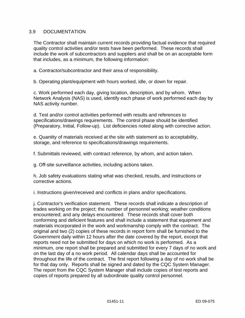
3.9 DOCUMENTATION
The Contractor shall maintain current records providing factual evidence that required quality control activities and/or tests have been performed. These records shall include the work of subcontractors and suppliers and shall be on an acceptable form that includes, as a minimum, the following information: a. Contractor/subcontractor and their area of responsibility. b. Operating plant/equipment with hours worked, idle, or down for repair. c. Work performed each day, giving location, description, and by whom. When Network Analysis (NAS) is used, identify each phase of work performed each day by NAS activity number. d. Test and/or control activities performed with results and references to specifications/drawings requirements. The control phase should be identified (Preparatory, Initial, Follow-up). List deficiencies noted along with corrective action. e. Quantity of materials received at the site with statement as to acceptability, storage, and reference to specifications/drawings requirements. f. Submittals reviewed, with contract reference, by whom, and action taken. g. Off-site surveillance activities, including actions taken. h. Job safety evaluations stating what was checked, results, and instructions or corrective actions. i. Instructions given/received and conflicts in plans and/or specifications. j. Contractor's verification statement. These records shall indicate a description of trades working on the project; the number of personnel working; weather conditions encountered; and any delays encountered. These records shall cover both conforming and deficient features and shall include a statement that equipment and materials incorporated in the work and workmanship comply with the contract. The original and two (2) copies of these records in report form shall be furnished to the Government daily within 12 hours after the date covered by the report, except that reports need not be submitted for days on which no work is performed. As a minimum, one report shall be prepared and submitted for every 7 days of no work and on the last day of a no work period. All calendar days shall be accounted for throughout the life of the contract. The first report following a day of no work shall be for that day only. Reports shall be signed and dated by the CQC System Manager. The report from the CQC System Manager shall include copies of test reports and copies of reports prepared by all subordinate quality control personnel.
01451-11 ED 09-075

01451-12 ED 09-075
3.10 SAMPLE FORMS
Sample forms for guidance in preparing the CQC Plan are enclosed at the end of this section.
3.11 NOTIFICATION OF NONCOMPLIANCE
The Contracting Officer will notify the Contractor of any detected noncompliance with the foregoing requirements. The Contractor shall take immediate corrective action after receipt of such notice. Such notice, when delivered to the Contractor at the work site, shall be deemed sufficient for the purpose of notification. If the Contractor fails or refuses to comply promptly, the Contracting Officer may issue an order stopping all or part of the work until satisfactory corrective action has been taken. No part of the time lost due to such stop orders shall be made the subject of claim for extension of time or for excess costs or damages by the Contractor.

Construction Control Manual Sampling & Testing
Construction Materials
Reporting Test Results CEMVN PAM 415-X-X 1 June 2008
DEPARTMENT OF THE ARMY NEW ORLEANS DISTRICT, CORPS OF ENGINEERS
P.O. BOX 60267 NEW ORLEANS, LOUISIANA 70160-0267
5/15/08
CEMVN-CD Pamphlet Number CEMVN-CD-415-X-X 1 June 2008
Construction
CONSTRUCTION CONTROL MANUAL 1. Purpose. This manual describes the means and methods for the Contractor Quality Control (CQC) and Government Quality Assurance (QA) testing of some of the more common construction materials incorporated into New Orleans District projects. Information is given on sampling, the test required, testing frequency, reporting requirements, and database maintenance. This manual only describes a minimum testing program on a limited number of common construction materials and the specifications may require additional tests that demonstrate compliance with the contract documents. 2. Applicability. This manual applies to all New Orleans District elements having responsibility for the design and construction of assigned projects. 3. Scope of the Manual. This manual is intended to guide the Quality Control and Quality Assurance process and provide for the construction of a project whose quality and durability is a direct reflection of the Contractor’s and the Government’s efforts in meeting the project’s goals and objectives. If there is a conflict between this manual and the technical specification sections, the most stringent requirements shall govern.
ALVIN B. LEE COL, MVN
Commanding

i
DEPARTMENT OF THE ARMY U.S. ARMY ENGINEER DISTRICT, NEW ORLEANS
CORPS OF ENGINEERS P.O. BOX 60267
NEW ORLEANS, LOUISANA 70160-0267 Pamphlet No. CEMVN-CD-415- X-X 1 June 2008
Construction CONSTRUCTION CONTROL MANUAL
Table of Contents
Page
Chapter 1 – Introduction General 1-1 Definitions 1-1 Responsibility, Compilation, and Submittal of Test Results 1-1 Chapter 2 – Soils 2.1. Scope 2-1 2.2. Samples 2-1 2.3. Tests 2-1 2.4. Sampling and Testing of Compacted Embankments and Berms, 2-2
Ramps and Structural Backfill Material 2.5. Sampling and Testing of Un-Compacted Berm Material 2-2 2.6. Compilation of Test Data for Submittal 2-3 Soil Testing Forms (see list of figures below) Chapter 3 – Concrete 3.1. Scope 3-1 3.2. Samples 3-1 3.3. Typical Test Requirements 3-1 Aggregate and Concrete Forms (see list of figures below) Chapter 4 – Welding 4.1. Scope 4-1 4.2. Definitions 4-1 4.3. Testing Personnel 4-1

ii
4.4. Visual Inspection Requirements 4-2 4.5. Nondestructive Testing Requirements 4-2 4.6. Acceptance Criteria 4-2 4.7. Frequency of Testing 4-2 Weld Testing Forms (see list of figures below) Appendices
Appendix A, Testing Database A-1 Appendix B, Material Testing Laboratory Requirements B-1
List of Figures Soil Testing Forms Figure 2-1, Compaction – Moisture Density Relationship – ASTM D 698 Figure 2-2, One-Point Proctor – ASTM D 698 (modified, under development) Figure 2-3, Field Density – Sand Cone Method – ASTM D 1556 Figure 2-4, Field Density – Nuclear Method – ASTM D 6938
Figure 2-5, Moisture Content Determination – ASTM D 2216 (Method B) Figure 2-6, Moisture Content Determination – ASTM D 4643
Figure 2-7, Moisture, Ash, and Organic Content Determination – ASTM D 2974 (Method C)
Figure 2-8, Liquid Limit, Plastic Limit, and Plasticity Index – ASTM D 4318 Figure 2-9, Sieve Analysis – ASTM C 117 and ASTM C 136 Aggregate and Concrete Forms Figure 3-1, Concrete Compression Specimen Data Figure 3-2, Instruction for form Figure 3-3, Aggregate Data Sheet Figure 3-4, Concrete Field Data Welding Forms Figure 4-1, Welds-Visual Inspection Figure 4-2, Welds-Ultrasonic Inspection Figure 4-3, Welds-Magnetic Particle Inspection Figure 4-4, Welds-Liquid Penetrant Inspection Figure 4-5, Welds-Radiographic Inspection

1-1
Chapter 1
Introduction 1-1. General. This manual describes the means and methods for the Contractor Quality Control and Government Quality Assurance testing of construction materials incorporated into the New Orleans District (CEMVN) projects. Information is given on sampling, the test required, testing frequency, reporting requirements, and database maintenance. This manual only describes a minimum testing program on a limited number of common construction materials and the specifications may require additional tests that demonstrate compliance with the contract documents. If there is a conflict between this manual and the technical specification sections, the most stringent requirements shall govern. The most recent version of this manual at the time of contract solicitation will supplement the construction material control requirements for a specific contract unless noted otherwise. 1-2. Definitions.
a. Quality Management System. Quality management is defined as all control, inspection, and other assurance activities instituted to achieve the product quality established by the contract plans and specifications.
b. Contractor Quality Control. Contractor Quality Control (CQC) is that part of
the system by which the Contractor regulates, tests and inspects their own, suppliers, and subcontractors procedures, equipment, materials, and personnel so that the completed product will comply with the requirements of the project’s contract documents.
c. Government Quality Assurance. Government Quality Assurance (QA) is that
part of the system by which the Government verifies or assures that the Contractor’s Quality Control system is performing properly and the completed product conforms to the contract documents. The number of CQC test observed by QA personnel should be generally related to the consistency in CQC and QA test results. 1-3. Responsibility, Compilation, and Submittal of Test Results.
a. The contractor is responsible for complying with the contract documents in the performance of all required tests and the preparation, submittal, and maintenance of those test reports outlined in this manual and the contract specifications. The test results from QC and QA testing shall be compiled separately as outlined in this manual.
b. All test results will be entered into the CEMVN material testing database as
described in Appendix A. Test results will be entered into the testing database within 24 hours after test completion. Payment for any material placed, as well as for any subsequent construction, will not be made until test results are entered into the database and analyzed by Quality Control and Quality Assurance personnel. The Contractor shall maintain a hard copy of the materials testing log and test reports at the Contractor’s field

1-2
office. These records will be available at all times for review by Government personnel. The original test report will be distributed to the Administrative Contracting Officer (ACO) within 48 hours of completion of the test. This original test report submission is in addition to any required electronic submission.
c. Any failing tests, i.e. those not indicating conformance with the contract
documents, will be immediately reported to the Administrative Contracting Officer along with the recommended corrective action to bring the work into complete compliance with the specifications. The Administrative Contracting Officer may designate additional re-sampling or retesting to verify the work represented by the failing test. This testing is at the Contractor’s expense.
d. Reference to standard test methods and testing procedures for sampling and
testing of common construction materials are given in each chapter of this manual. Additional testing may also be required in the contract documents.
e. Random Quality Assurance tests will provide further assurance of the
contractor’s compliance with the contract requirements and specifications. These results will also be entered into the testing database for record purposes. Quality Assurance testing will be as described in the contract specific QA plan but the recommended minimum testing frequency is five percent of the number of quality control tests.
f. Laboratory Facilities. The contractor shall only use those laboratories,
including his own that have been inspected and/or validated by an inspection or audit performed by the Materials Testing Center, Corps of Engineers. Appendix B further describes this requirement. Refer to Chapter 4 for welding laboratories.

2-1
Chapter 2
Soils 2-1. Scope. This chapter prescribes methods and procedures for the Contractor Quality Control (CQC) and Government Quality Assurance (QA) testing of materials used in compacted levee embankments and berms, un-compacted berms, ramps, and structural backfill. 2-2. Samples. Samples shall be collected and secured in accordance with individually specified ASTM testing procedures as applicable. 2-3. Tests. Testing and reporting shall be performed in accordance with the American Society of Testing and Materials (ASTM) Standards as indicated below in Table 2-1.
Table 2-1
ASTM References
Gradation ASTM C 136 Sieve or Screen Analysis of Fine and Course
Aggregates ASTM C 117 Materials Finer than No. 200 Sieve in Mineral
Aggregates by Washing Moisture Content
ASTM D 2216 Laboratory Determination of Water, (Moisture) Content of Soil and Rock by Mass (Method B)
ASTM D 4643 Determination of Water (Moisture) Content of Soil by Microwave Method
Moisture/Density Relationship ASTM D 698 Laboratory Compaction Characteristics of Soil
Using Standard Efforts (12,400ft lbs/ft^3 (6000KN)) Field Density
ASTM D 1556 Density and Unit Weight of Soil in Place by the Sand-Cone Method
ASTM D 6938 In-Place Density and Water Content of Soil and Soil-Aggregate Nuclear Methods (Shallow Depth)
Materials Classification ASTM D 2487 Classification of Soils for Engineering Purposes
ASTM D 4318 Liquid Limit, Plastic Limit, and Plasticity Index of
Soils Organic Content
ASTM D 2974 Moisture, Ash, and Organic Matter of Peat and Other Organic Soils (Method C)

2-2
2-4. Sampling and Testing of Compacted Embankments and Berms, Ramps, and Structural Backfill Material. This sampling and testing shall be in accordance with the standard procedures referred to in this manual. The minimum number of CQC tests to be performed shall be as indicated in Table 2-2.
Table 2-2
Type of Tests and Frequency of Testing
Compacted Embankments and Berms, Ramps, and Structural Backfill Material
Frequency Standard
Field Density
One test per 1,500 cubic yards of compacted fill placed per lift, but not less than one density test per 500 linear feet per lift. A lift placed on any one side of an existing embankment will be considered as a separate lift. At least one test shall be performed in any shift that compacted fill is placed.
ASTM D 1556
ASTM D 6938 (11.3.2 only, ASTM D 3017
is not applicable to field density testing)
Moisture/Density Determination Two control compaction curves will be required for each type of material from each source. Where construction operations result in blending of several types of material prior to or during fill placement, two control compaction curves will be required for each resulting blend of material and will be utilized in lieu of those required for the "unblended materials". The average of the two tests shall be the controlling optimum moisture content and maximum density.
ASTM D 698
One-Point Proctor Verification One test to be obtained for every five (5) field density locations.
ASTM D 698 (modified, under development)
Moisture Content One test at each field density test location.
ASTM D 2216 (at lab) ASTM D 4643 (in field)
Organic Content
One test at each field density test location.
ASTM D 2974 (Method C)
Materials Classification
One test obtained for each control compaction curve and one test for each field density test.
ASTM D 2487 ASTM D 4318 ASTM C 136 ASTM C 117

2-3
2-5. Sampling and Testing of Un-Compacted Berm Material. This sampling and testing shall be in accordance with the standard procedures referred to in this manual. The minimum number of QC tests to be performed shall be as indicated in Table 2-3.
Table 2-3
Type of Tests and Frequency of Testing
Un-Compacted Berm Material
Frequency Standard
Organic Content
One test at materials classification test location.
ASTM D 2974 (Method C)
Materials Classification
One test per 3,000 cubic yards of un-compacted fill placed, but not less than one test per 1,000 linear feet of un-compacted fill placed. At least one test shall be performed in any shift that un-compacted fill is placed.
ASTM D 2487 ASTM D 4318 ASTM C 136 ASTM C 117
2-6. Compilation of Test Data for Submittal. The results of the following tests shall be recorded in the MVN testing database. Samples of the reporting forms are given in this chapter and described as follows.
a. Compaction – Moisture Density Relationship Determination – ASTM D 698
(Figure 2-1). This form is to be used in reporting the determination of the optimum moisture content and the maximum dry density. The moisture-density curve shall be plotted based on a minimum of five compaction test specimens. The results shall be submitted electronically within 24 hours of the test. A one-point Proctor test – ASTM D 698 (modified, Figure 2-2) shall be obtained for every five (5) field density test locations, and reported with same.
b. Field Density – Sand Cone Method – ASTM D 1556 (Figure 2-3). This form
is to be used in reporting the determination of the degree of compaction. Contract specifications shall govern the required compaction effort. The results shall be submitted electronically within 24 hours of the test.
c. Field Density Test – Nuclear Method – ASTM D 6938 (Figure 2-4). This form
is to be used in reporting the determination of the degree of compaction. Contract specifications shall govern the required compaction effort. If the nuclear method is selected for field density testing, the sand-cone method shall be used to confirm the accuracy of the nuclear method. This confirmation shall be accomplished by performing an initial comparison test of the two methods at the start of construction. The initial comparison test shall be determined by conducting ten comparison tests (five D-6938 & five D-1556) and calculating the average difference (correction) for each soil type encountered. For comparison purposes, the nuclear and sand-cone wet densities should

2-4
represent the same layer thickness within the testing area selected. The nuclear method wet density shall be verified throughout the project at a rate of one sand-cone test for every ten nuclear tests thereafter. If the nuclear method wet density is within three percent (3%) of the sand cone method, no correction of the nuclear method wet density will be required and the testing may continue with the nuclear method. If the variance at any time exceeds three percent (3%), a correction factor will be required to be determined prior to any further testing. The correction factor shall be determined by conducting ten comparison tests (five D-6938 & five D-1556) and calculating the average difference (correction) for each soil type encountered. The developed correction shall be used for adjusting the nuclear wet density readings. When a field density result is in doubt, the sand-cone density test shall be considered the rule for acceptance. The results shall be submitted electronically within 24 hours of the test.
d. Moisture Content Determination – ASTM D 2216 (Method B) (Figure 2-5).
This form is to be used in reporting the determination of the moisture content of the material when ASTM D 2216 (Method B) is the test method utilized. Contract specifications shall govern the acceptable limits of moisture content. The results shall be submitted electronically within 24 hours of the test.
e. Moisture Content Determination – ASTM D 4643 (Figure 2-6). This form is
to be used in reporting the determination of the moisture content of the in-place material when ASTM D 4643 is the test method utilized. Contract specifications shall govern the acceptable limits of moisture content. The results shall be submitted electronically within 24 hours of the test.
f. Moisture, Ash, and Organic Content Determination – ASTM D 2974 (Method
C) (Figure 2-7). This form is to be used in reporting the determination of the organic content of the material. Determination of organic content shall be performed in accordance with ASTM D 2974, Method C. Contract specifications shall govern the acceptable limits of organic content. The results shall be submitted electronically within 48 hours of the test.
g. Material Classification (Figure 2-8 and Figure 2-9). Liquid Limit, Plastic
Limit, and Plasticity Index – ASTM D 4318 (Figure 2-8) is to be used to report the determination of the liquid limit, plastic limit, and plasticity index of the material if a non-granular material is specified for structural backfill, and also for all embankment fill. Sieve Analysis – ASTM C 117 and ASTM C 136 (Figure 2-9) is to be used to report the results of gradation tests of the material if a granular material is specified for structural backfill. The final soil classification in accordance with ASTM D 2487 shall be stated on same forms. Contract specifications shall govern the acceptable Atterberg limits, gradation limits, and material classification. If the Nuclear Method (ASTM D 6938) is used for field density determinations, the soil sample utilized for material classification shall come from within a radius of 12 inches of the center of the in-place density test site. The soil classification obtained from in-place density tests will serve as the basis for determining the applicable control compaction curves. The results shall be submitted electronically within 24 hours of the test.
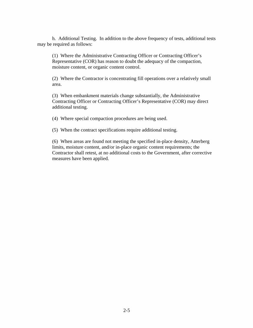
2-5
h. Additional Testing. In addition to the above frequency of tests, additional tests
may be required as follows: (1) Where the Administrative Contracting Officer or Contracting Officer’s Representative (COR) has reason to doubt the adequacy of the compaction, moisture content, or organic content control. (2) Where the Contractor is concentrating fill operations over a relatively small area. (3) When embankment materials change substantially, the Administrative Contracting Officer or Contracting Officer’s Representative (COR) may direct additional testing. (4) Where special compaction procedures are being used. (5) When the contract specifications require additional testing. (6) When areas are found not meeting the specified in-place density, Atterberg limits, moisture content, and/or in-place organic content requirements; the Contractor shall retest, at no additional costs to the Government, after corrective measures have been applied.

Laboratory Test IDUSACE Contract Number ContractorProject DateSource of Material Feature Visual Description (ASTM D 2488)Station Offset Lift NumberX-Coordinate Y-Coordinate Elevation (ft)Test Method Preparation Method As-Received Moisture ContentHand / Mechanical Rammer Specific GravityPercent Retained - No. 4 Sieve Percent Retained - 3/8" Sieve Percent Retained - 3/4" Sieve Oversize Fraction ASTM D 3718 Correction - Yes/NoTested By Checked By Submitted ByTest Sequence Number 1 2 3 4 5a. Mold Numberb. Mass of Mold (g)c. Volume of Mold (cf)d. Mass of Wet Soil+Mold (g)e. Mass of Wet Soil (g) f. Wet Unit Weight (lbs/cf)g. Container No.h. Mass of Tare (g)i. Mass of Wet Soil+Tare (g)j. Mass of Dry Soil+Tare (g)k. Mass of Water (g) l. Mass of Dry Soil (g) m. Moisture Content % n. Dry Unit Weight (lbs/cf)
Compaction Curve Control No. Optimum Moisture Content (%)Max. Dry Unit Weight (lbs/cf)
Classification of Sample
Liquid LimitPlastic Limit
Plasticity Index Symbol From Plastic Chart:
% Passing 200% Passing No. 4
Test Results
Remarks:
Liquid And Plastic Limits
Compaction - Moisture Density Relationship - ASTM D 698
Specific Gravity Method: As Tested or Estimated
Compaction Curve
85.0
86.0
87.0
88.0
89.0
90.0
91.0
92.0
93.0
94.0
95.0
15 16 17 18 19 20 21 22
Moisture Content, %
Dry
Uni
t Wei
ght,
lbs/
cf
85
Dry Unit Weight ScaleMin 95Max
15
Moisture Content % ScaleMin 22Max Change
Graph Scale
FIGURE 2-1

LaboratoryUSACE Contract NumberProjectSource of MaterialStationX-CoordinateTested By
Remarks:
Moisture Content
n. Wet Unit Weight (lbs/cf)
l. Volume of Test Hole (cubic cm)m. Dry Mass of Soil Removed from Hole (g)
5. Bulk-Density of Sand (g/cubic cm)
Comparison of Field Density and Maximum Density
w. Moisture Content (%)
s. Mass of Wet Sample + Container (g)t. Mass of Dry Sample + Container (g) u. Mass of Water (g)
q. Container Number
i. Mass of Sand in Test Hole (g) j. Mass of Wet Soil Removed from Hole (g) k. Bulk-Density Sand (g/cubic cm) (from 5)
3. Mass of Sand (g) 4. Vol. of Calibration Container (cubic cm)
e. Mass of Apparatus and Sand (Initial) (g)f. Mass of Apparatus and Sand (Finish) (g)g. Mass of Sand Used (g)
d. Mass of Sand in Cone and Plate (g)
Bulk Density of Sand
c. Mass of Apparatus (after Cone Fill) (g) b. Mass of Initial Apparatus with Sand (g)
Calibration of Sand Cone Funnel And Plate
Checked By
2. Mass of Calibration Container (g)
Retest Of Test ID
FeatureOffsetY-Coordinate
Visual Description (ASTM D 2488)Lift NumberElevation (ft)
Date
Submitted By
Field Density - Sand Cone Method - ASTM D 1556
a. Apparatus Number 1. Mass of Sand + Calibration Container (g)
Test IDContractor
Density Determination
6. Compaction Curve Control Number7. Optimum Moisture (Control C) (%)8. Max. Dry Unit Weight (Control C) (lbs/cf)9. Compaction Required (%)10. Degree of Compaction (%)
h. Mass of Sand in Cone/Plate (g) (from d)
12. Mass Retained No. 4 (g)
v. Mass of Dry Sample (g)
p. Moisture Content Method
13. Mass Passing No. 4 (g)
o. Dry Unit Weight (lbs/cf)
11. Difference from Opt. Moisture (%) (+/-)
r. Mass of Container (g)
14. Total Mass (g)
FIGURE 2-3
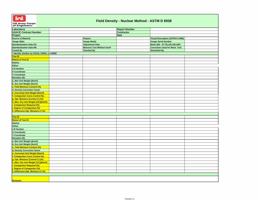
Laboratory Report NumberUSACE Contract Number ContractorProject DateSource of Material Feature Visual Description (ASTM D 2488)Gauge Make Gauge Model Gauge Serial NumberStandardization Data DS Adjustment Data Mode (BS - DT 50,100,150,200)Standardization Data MS Moisture Test Method Used* Correction Used for Moist. TestTested By Checked By Submitted By
Test IDRetest of Test IDStationOffsetLift NumberX-CoordinateY-Coordinate Elevation (ft)a. Wet Unit Weight (lbs/cf)b. Dry Unit Weight (lbs/cf)c. Field Moisture Content (%)d. Density Correction Factore. Corrected Unit Weight (lbs/cf)f. Compaction Curve Control No.g. Opt. Moisture (Control C) (%)h. Max. Dry Unit Weight (CC)(lbs/cf) i. Compaction Required (%)j. Degree of Compaction (%)k. Difference-Opt. Moisture (+/-%)
Test IDRetest of Test IDStationOffsetLift NumberX-CoordinateY-Coordinate Elevation (ft)a. Wet Unit Weight (lbs/cf)b. Dry Unit Weight (lbs/cf)c. Field Moisture Content (%)d. Density Correction Factore. Corrected Unit Weight (lbs/cf)f. Compaction Curve Control No.g. Opt. Moisture (Control C) (%)h. Max. Dry Unit Weight (CC)(lbs/cf) i. Compaction Required (%)j. Degree of Compaction (%)k. Difference-Opt. Moisture (+/-%)
* Identify whether by D2216, D4643, or D4959
Field Density - Nuclear Method - ASTM D 6938
Remarks:
FIGURE 2-4

Laboratory Report NumberUSACE Contract Number ContractorProject DateSource of Material Feature Visual Description (ASTM D 2488)Date / Time In Oven Date / Time Out of Oven Oven UsedTested By Checked By Submitted By
Test IDRetest Of Test IDStationOffsetLift NumberX-CoordinateY-Coordinate Elevation (ft)
a. Container / Lid Numberb. Wet Soil + Tare Mass (g)c. Dry Soil + Tare Mass (g)d. Water Mass (g)e.Tare Mass (g)f. Dry Soil Mass (g) Moisture Content (%)Optimum Moisture Content (%)Difference from Opt. Moisture
Test IDRetest Of Test IDStationOffsetLift NumberX-CoordinateY-Coordinate Elevation (ft)
a. Container / Lid Numberb. Wet Soil + Tare Mass (g)c. Dry Soil + Tare Mass (g)d. Water Mass (g)e.Tare Mass (g)f. Dry Soil Mass (g) Moisture Content (%)Optimum Moisture Content (%)Difference from Opt. Moisture
Moisture Content Determination - ASTM D 2216 (Method B)
Remarks:
FIGURE 2-5

Report NumberContractorDate
Feature Visual Description (ASTM D 2488)
Checked By Submitted By
c. After 3 min (Soil+Tare)(g) d. Plus 1 min. (Soil+Tare)(g) e. Plus 1 min. (Soil+Tare)(g) f. Plus 1 min. (Soil+Tare)(g) g. Plus 1 min. (Soil+Tare)(g) h. Plus 1 min. (Soil+Tare)(g)
c. After 3 min (Soil+Tare)(g) d. Plus 1 min. (Soil+Tare)(g) e. Plus 1 min. (Soil+Tare)(g) f. Plus 1 min. (Soil+Tare)(g) g. Plus 1 min. (Soil+Tare)(g) h. Plus 1 min. (Soil+Tare)(g)
LaboratoryUSACE Contract Number
Test ID
Y-Coordinate
Tested By
ProjectSource of Material
Moisture Content Determination - ASTM D 4643
Microwave Oven Used
StationOffset
Retest Of Test ID
j. Water Mass (g) (b-i)
Retest Of Test ID
k. Tare Mass (g)
Lift NumberX-Coordinate
Elevation (ft)
i. Dry Soil+Tare (Final) (g)
a. Container / Lid Numberb. Wet Soil+Tare (Initial) (g)
Required Moisture Content (%)
Test ID
StationOffset
Y-Coordinate
Lift NumberX-Coordinate
Incr
emen
tal M
easu
rem
ent
b. Wet Soil+Tare (Initial) (g)
j. Water Mass (g) (b-i)k. Tare Mass (g)
l. Dry Soil Mass (g) (i-k)
Elevation (ft)
Incr
emen
tal M
easu
rem
ent
i. Dry Soil+Tare (Final) (g)
Moisture Content(%)((j/l) x 100))
a. Container / Lid Number
Moisture Content(%)((j/l) x 100))
Remarks:
l. Dry Soil Mass (g) (i-k)
Required Moisture Content (%)
FIGURE 2-6

Laboratory Report NumberUSACE Contract Number ContractorProject DateSource of Material FeatureFurnace Temperature Oven UsedTested By Checked By Submitted By
Test IDStationOffsetLift NumberX-CoordinateY-Coordinate Elevation (ft)
a. Ash Dish Container Numberb. Dried Soil + Tare Mass (g)c. Ash Dish Tare Mass (g)d. Dried Soil Mass (g)e. Ashed Soil+Tare Mass (g)f. Ashed Soil Mass (g) g. Ash Content (%) h. Organic Matter (%) i. Max. Allow. Organic Matter (%)
Test IDStationOffsetLift NumberX-CoordinateY-Coordinate Elevation (ft)
a. Ash Dish Container Numberb. Dried Soil + Tare Mass (g)c. Ash Dish Tare Mass (g)d. Dried Soil Mass (g)e. Ashed Soil+Tare Mass (g)f. Ashed Soil Mass (g) g. Ash Content (%) h. Organic Matter (%) i. Max. Allow. Organic Matter (%)
Moisture, Ash, and Organic Content Determination - ASTM D 2974 (Method C)
Remarks:
Visual Description (ASTM D 2488)
FIGURE 2-7

Test Sequence Number 6a. Container Numberb. Wet Soil+Tare Mass (g)c. Dry Soil+Tare Mass (g)d. Water Mass (g)e. Tare Mass (g)f. Dry Soil Mass (g)g. Moisture Content (%)h. Number of Blows
Test Sequence Number 6i. Container Numberj. Wet Soil+Tare Mass (g)k. Dry Soil+Tare Mass (g)l. Water Mass (g)m. Tare Mass (g)n. Dry Soil Mass (g)o. Moisture Content (%)
Classification Symbol
Plasticity Index
Specified Liquid Limit (%)Liquid Limit (%)
Plastic Limit (%)
Specified Plasticity Index (%)
Liquid Limit, Plastic Limit, and Plasticity Index - ASTM D 4318
4
Submitted By
Lift Number
Test ID
5
ContractorDate
Visual Description (ASTM D 2488)
Elevation (ft)Checked By
3Liquid Limits
1 2
Y-Coordinate OffsetStation
X-CoordinateTested By
Feature
LaboratoryUSACE Contract NumberProjectSource of Material
1 2 3 4 5
Remarks:
Plastic Limit
Flow Curve
40302010525
30
35
40
45
50
55
60
65
70
75
Number of Blows
Moi
stur
e C
onte
nt (%
)
FIGURE 2-8
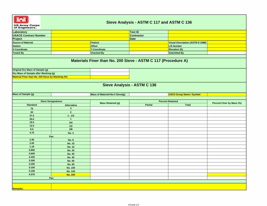
Laboratory Test IDUSACE Contract Number ContractorProject DateSource of Material Feature Visual Description (ASTM D 2488)Station Offset Lift NumberX-Coordinate Y-Coordinate Elevation (ft)Tested By Checked By Submitted By
Mass of Sample (g) Mass of Material>No.4 Sieve(g) USCS Group Name / Symbol
Standard Alternative Partial Total 75 350 2
37.5 1 - 1/225.0 119.0 3/412.5 1/29.5 3/84.75 No. 4
2.36 No. 82.00 No. 101.18 No. 160.850 No. 200.600 No. 300.425 No. 400.300 No. 500.250 No. 600.150 No. 1000.106 No. 1400.075 No. 200
Original Dry Mass of Sample (g)
Pan
Pan
Percent Finer by Mass (%)
Materials Finer than No. 200 Sieve - ASTM C 117 (Procedure A)
Sieve Analysis - ASTM C 136
Remarks:
Percent RetainedSieve DesignationsMass Retained (g)
Dry Mass of Sample after Washing (g)Material Finer than No. 200 Sieve by Washing (%)
Sieve Analysis - ASTM C 117 and ASTM C 136
FIGURE 2-9

Chapter 3
Concrete 3-1. Scope. This chapter prescribes methods and procedures for the testing of concrete and concrete aggregates. This section does not supersede contract documents. 3-2. Samples. Concrete samples shall be secured in accordance with ASTM C 172. Concrete aggregates shall be sampled in accordance with ASTM D 75 3-3. Typical Test Requirements. Test requirements specified in the contracts documents may be more stringent than those listed below in Table 3-1. Appropriate report forms are shown at the end of this chapter. All test data will be entered in the CEMVN material testing database. Acceptable test values are contained in the contract documents.
Table 3-1 Test Requirements
Property Method Form Frequency Remarks AGGREGATE, FINE
Deleterious Substances
ASTM C 33 AF 1 per week When COR requires
Fineness Modulus
CRD-C 104 AF 1 per shift when concrete plant is operating
Calculation based on gradation test results
Gradation ASTM C 136 AF 1 per shift when concrete plant is operating
Tests selected randomly
If moisture meter is working properly, 2 per week to verify If moisture meter is not working, 4 every 8 hrs of mixing plant operation
Moisture content
ASTM C 566 AF
Additional tests if slump is out of control or variability is excessive
Tests selected randomly
3-1

Table 3-1 Test Requirements (continued)
Property Method Form Frequency Remarks AGGREGATE, COARSE
Deleterious Substances
ASTM C 33 Eng Form 6011-R
1 per week When COR requires
Gradation ASTM C 136 Eng Form 6011-R
1 per shift when concrete plant is operating
Tests selected randomly for each aggregate size
2 per week Moisture Content
ASTM C 566 Eng Form 6011-R
When two consecutive readings for smallest size differ by more than 1.0 percent, frequency of testing shall be increased to 4 every 8 hours until the difference falls below 1.0 percent
Tests selected randomly for each aggregate size
CONCRETE MVN 835-R
CF 1 every time concrete cylinders are molded
plus two additional during each 8 hours of concrete production
Air Content ASTM C 231
Additional tests if workability variation is excessive
On randomly selected batches for each separate concrete mix produced
Compression Cylinders (for acceptance testing)
ASTM C 31 ASTM C 39
MVN 835-RCF
1 set of 3 cylinders for each increment or fraction of 150 cubic yards placed during every 8-hour shift
On randomly selected batches for each separate concrete mix produced Cure in accordance with paragraph 10.2 of ASTM C 31
1 set of 4 cylinders per day (6 if 90-day strengths are specified)
Compression Cylinders (for quality control)
ASTM C 31 ASTM C 39
MVN 835-RCF
Additional sets when mix proportions change or low strengths are detected
On randomly selected batches for each separate concrete mix produced Cure in accordance with paragraph 10.2 of ASTM C 31
3-2

Table 3-1 Test Requirements (continued)
Property Method Form Frequency Remarks Compression Cylinders (for form stripping, putting concrete into service, or other purposes indicated in paragraph 4.3 of ASTM C 31)
ASTM C 31 ASTM C 39
MVN 835-R
1 set of multiple pairs of cylinders per item to be evaluated
Cure in accordance with paragraph 10.2 of ASTM C 31
MVN 835-RCF
1 every time concrete cylinders are molded
plus 4 additional during each 8 hours of concrete production
Slump ASTM C 143
Additional tests if workability variation is excessive
On randomly selected batches for each separate concrete mix produced
MVN 835-RCF
1 every time concrete cylinders are molded
Temperature ASTM C 1064
Additional readings when temperature is near or out of specified limits
3-3

Test IDContractor
Test DateConcrete SupplierTested BySpecified StrengthSpecified (W/C+P) Y-Coordinate
Field Water (gal)Sample Obtained From Slump (in) Air Content
Cement (C) lbs
Pozzolan (P) lbs
Fine Ag Water Coarse Ag Water Batch Ice Field Total Water lbsTime Batched Time Molded Molded By Temps: Air (F) Concrete (F) W/(C+P) act
Delivered by COE A-E ContractorCushioning
method Date received
Fine Aggregate
Compressive Strength (psi)Tested By Break TypeTotal Load
(lbs)Height (in) Diameter (in) Area (sq in)
Aggregate Absorption (Percent)
Size/ GradeAggregate Moisture (Percent)
Excess Moisture (lbs)
Speciman Marking Test At (Days) Date to be Tested Tested At (Days)
Coarse Aggregate NMS (in)
Aggregate Batch Weight
(lbs)
USACE Contract NumberLaboratory
Concrete Compression Test Specimen Data
Project Name
Pit/ Quarry Name
Time cured in water tank on job site at 73.4 plus or minus 3 degrees F after intial curing hrs Date delivered to lab
Description
Placement LocationMix Designation
X-Coordinate
FIGURE 3-1
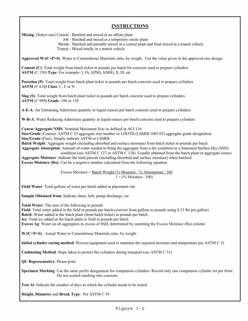
Figure 3-2
INSTRUCTIONS
Mixing: (Select one) Central - Batched and mixed at an offsite plant Job - Batched and mixed at a temporary onsite plant Shrink - Batched and partially mixed at a central plant and final mixed in a transit vehicle Transit - Mixed totally in a transit vehicle Approved W/(C+P+S): Water to Cementitious Materials ratio, by weight. Use the value given in the approved mix design. Cement (C): Total weight from batch ticket in pounds per batch for concrete used to prepare cylinders ASTM (C 150) Type: For example- I, IA, I(PM), I(MH), II, Ill, etc Pozzolan (P): Total weight from batch plant ticket in pounds per batch concrete used to prepare cylinders ASTM (C 618) Class: C, F or N Slag (S): Total weight from batch plant ticket in pounds per batch concrete used to prepare cylinders ASTM (C 989) Grade: 100 or 120 A-E-A: Air Entraining Admixture quantity in liquid ounces per batch concrete used to prepare cylinders W-R-A: Water Reducing Admixture quantity in liquid ounces per batch concrete used to prepare cylinders Coarse Aggregate NMS: Nominal Maximum Size as defined in ACI 116 Size/Grade (Coarse): ASTM C 33 aggregate size number or LDOTD (LSSRB 1003.02) aggregate grade designation Size/Grade (Fine): Simply indicate ASTM or LSSRB Batch Weight: Aggregate weight (including absorbed and surface moisture) from batch ticket in pounds per batch Aggregate Absorption: Amount of water needed to bring the aggregate from a dry condition to a Saturated Surface Dry (SSD)
condition (see ASTM C 127 or ASTM C 128). Usually obtained from the batch plant or aggregate source Aggregate Moisture: Indicate the total percent (including absorbed and surface moisture) when batched. Excess Moisture (lbs): Can be a negative number calculated from the following equation Excess Moisture = Batch Weight (% Moisture - % Absorption) / 100 1 + (% Moisture / 100) Field Water: Total gallons of water per batch added at placement site Sample Obtained from: Indicate chute, belt, pump discharge, etc. Total Water: The sum of the following in pounds Field: Total water added in the field in pounds per batch (convert from gallons to pounds using 8.33 lbs per gallon) Batch: Water added at the batch plant (from batch ticket) in pounds per batch Ice: Total ice added at the batch plant or field in pounds per batch Excess Ag: Water on all aggregates in excess of SSD, determined by summing the Excess Moisture (lbs) column W/(C+P+S): Actual Water to Cementitious Materials ratio, by weight Initial cylinder curing method: Process/equipment used to maintain the required moisture and temperature per ASTM C 31 Cushioning Method: Steps taken to protect the cylinders during transport (see ASTM C 31) QC Representative: Please print Specimen Marking: Use the same prefix designation for companion cylinders. Record only one companion cylinder set per form.
Do not scratch marking into concrete. Test At: Indicate the number of days in which the cylinder needs to be tested. Height, Diameter and Break Type: Per ASTM C 39

Laboratory Test IDUSACE Contract Number ContractorProjectConcrete Supplier DescriptionTest DateTested By Checked By Submitted By
Sieve6 in5 in4 in3 in2 1/2 in2 in1 1/2 in1 in3/4 in1/2 in3/8 inNo. 4No. 8No. 16No. 30 Type Cement Ratio Days % Days %No. 50No. 100No. 200 -200(a) Parallel Across On AverageF.M. (b)
2 mo. 6 mo. 9 mo. 12 mo. 3 mo. 5 mo. 9mo. 12mo.Low- Alk. Cement: High- Alk. Cement:
F&T HW- CD HD-CWFine AGG. DFE308Fine AGG. DFE308
#4- 3/4" Fine AGG.
Remarks:
Grading (CRD-C 103) ( Cum. % Passing):
3-6" 1 1/2- 3" 3/4- 1 1/7
# 4- 1 1/4 Fine Agg.
Bulk SP GR, S.S.D. (CRD-C 107,108)Absorption, % (CRD-C 107,108):
3-6" 1 1/2- 3 3/4- 1 1/7Test Results
Organic Impurities, Fig. No. (CRD-C 121)Soft Particles, % (CRD-C 130)
% Lighter Than SP GR (CRD-C 122)% Flat and Elongated (CRD-C 119, 120)
WT AV % Loss, 5 Cyc Mg504 (CRD-C 115)L.A. Abrasion Loss, % (CRD-C 117, 145) Grading
Unit WT. LB/CU FT (CRD-C 106):Friable Particles, % (CRD-C 142)
(a) CRD-C 106 (b) CRD-C 104
Coarse AGG
Mortar:Mortar- Bar Expansion AT 100F, % (CRD-C 123):
Aggregate Data Sheet
Coarse Aggregate
Spec Heat, BTU/ LB/DEG F. (CRD-C 124)Reactivity with NoOH
(CRD-C 128):
Linear Thermal Expansion, Millionths/ DEG F. (CRD-C 125,126):Rock Type
Fine Aggregate
Soundness in Concrete (CRD-C 40, 114):
Petrographic Data (CRD-C 127) :
% N62O Equivalent:% N62O Equivalent:
Coarse AGG
5c, mM/L19c, mM/L
Mortar-Making Properties (CRD-C 116)
FIGURE 3-3
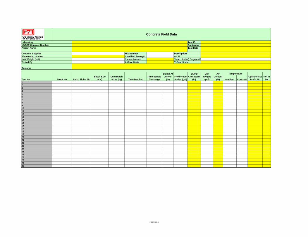
Test IDContractor
Mix NumberSpecified StrengthSlump (Inches)X-Coordinate
Ambient Concrete123456789101112131415161718192021222324252627282930
Test Date
Y-Coordinate
Concrete Field Data
DescriptionAir %Temp Limit(s) Degrees F
Placement LocationUnit Weight (pcf)Tested By
Remarks
LaboratoryUSACE Contract Number
Concrete Supplier
Project Name
Temperature
Truck No Batch Ticket NoField Water Added (gal)
Slump After Water
(in)
Unit Weight
(pcf)
Slump At Arrival
(in) Batch Size
(CY)Cum Batch Sizes (cy) Time Batched
Time Started Discharge
Cylinder Set Prefix No
No. In SetTest No
Air Content
(%)
FIGURE 3-4

Chapter 4
Welding 4.1. Scope. This Section specifies the weld testing requirements for Group 1 and Group 2 carbon steels as defined by AWS D1.1, Table 3.1 and their ASTM A709 counterparts. Welding of sheet metal, reinforcement bars, castings, stainless steel, aluminum and other non ferrous metals are not included in this document and should reference the appropriate AWS or ASME Code. 4.2. Definitions. a. Fracture Critical Welds. Fracture critical welds as defined by ER 1110-2-8157 are members or member components are tension members or tension components of bending members (including those subject to reversal of stress), the failure of which would be expected to result in collapse of the hydraulic steel structure. The designation “FCM” shall mean fracture critical member or member component. Members and components that are not subject to tensile stress under any condition of live load shall not be defined as fracture critical. FCMs, in general, are dewatering components (needle girders, bulkheads, needles), lifting eyes, or other tension members. This includes any members welded to these members as cracks could propagate to these members and cause failures also. These welds should either be shown on the drawings or called out in the specifications. Tubular welds are not applicable to AWS D1.5. AWS D1.5, Section 12 is the applicable code for these welds. b. Other Welds. These welds are the remaining welds that are not considered Fracture Critical Welds. AWS D1.1 is the applicable code for these welds. 4.3. Testing Personnel.
a. Visual Inspection. Visual inspection shall be performed by Certified Welding Inspectors (CWI) that are qualified and certified in accordance with the provisions of AWS QC1. Verification of documentation may be obtained from the AWS web site. Note: Certification number is required for this verification.
b. Nondestructive Testing Technicians. All ASNT Level III personal shall be qualified in accordance with ASNT CP-189. Only individuals qualified for NDT Level II or individuals qualified for Level I and working under the direct supervision of a Level II shall perform nondestructive testing. Level I and Level II personnel shall qualified in accordance with either ASNT CP-189 or ASNT SNT-TC-1A. Level III NDT Inspectors shall posses a currently valid ASNT Level III certificate in each of the processes they are qualifying inspectors to. Copies of the certifications, including the Level III NDT Technician that certified the Level I and Level II Technicians shall be included in the submittals. Verification of Level III documentation may be obtained from the ASNT web site. Note: Either Certification number or name is required for this verification.
4-1

4.4. Visual Inspection Requirements. Visual inspection of welds shall conform to the requirements of AWS D1.1, Section 6, or AWS D1.5 Section 12, as applicable. 4.5. Nondestructive Testing Requirements.
a. Ultrasonic Testing. Ultrasonic testing of welds shall conform to the requirements of AWS D1.1, Section 6, Part F or AWS D1.5 Subsection 12.16, as applicable.
b. Radiographic Testing. Radiographic testing of welds shall conform to the requirements of AWS D1.1, Section 6, Part E or AWS D1.5 Subsection 12.16, as applicable. Only film types designated as “fine grain” or “extra fine” shall be employed.
c. Magnetic Particle Inspection. Magnetic particle inspection of welds shall conform to the applicable provisions of ASTM E 709 or AWS D1.5 Subsection 12.16, as applicable and in addition all magnetic particle inspections of welds shall be made using the Wet Contrasting Black on White Method. 4.6. Acceptance Criteria.
a. Visual and Magnetic Particle Testing. Welds shall be unacceptable if shown to have defects prohibited by AWS D 1.1/D 1.1M, Section 6, Part C. Visual and magnetic particle testing acceptance criteria shall be for the applicable criteria for either “Cyclically Loaded Nontubular Connections” or “Tubular Connections” per AWS D 1.1/D 1.1M, Table 6.1. Fracture critical welds shall be unacceptable if shown to have defects prohibited by AWS D 1.5/D 1.5M, Section 12. All welds shall be assumed in tension for the acceptance criteria for visual and the appropriate nondestructive testing method. b. Ultrasonic Testing. Ultrasonic acceptance criteria shall be the applicable criteria for either “Cyclically Loaded Nontubular Connections” or “Tubular Connections, Class R”. Fracture critical welds shall be unacceptable if shown to have defects prohibited by AWS D 1.5/D 1.5M, Section 12. All welds shall be assumed in tension for the acceptance criteria for visual and the appropriate nondestructive testing method.
c. Radiographic Testing. Radiographic acceptance criteria shall be the applicable criteria for either “Cyclically Loaded Nontubular Connections (Tensile Stress)” or “Tubular Connections”. Fracture critical welds shall be unacceptable if shown to have defects prohibited by AWS D 1.5/D 1.5M, Section 12. All welds shall be assumed in tension for the acceptance criteria for visual and the appropriate nondestructive testing method. 4.7. Frequency of Testing. The frequency specified is the minimum required. The design engineer shall determine the required frequency and include this information in the specifications and/or drawings. The design engineer shall also specify the locations of radiographic testing.
4-2

a. Visual Inspection. All welds shall be visually inspected by a CWI to insure
compliance with the requirements of the applicable AWS Welding Code. Prior to any welding, a CWI shall visually inspect the preparation of material for welding to assure compliance with the applicable AWS Code (D1.1 or D1.5) and approved WPS. The CWI shall also perform VT inspection throughout the welding process to assure compliance with the applicable AWS Code (D1.1 or D1.5) and approved WPS. All completed welds shall be cleaned free of oxide, flux, scale, or other foreign matter before inspection.
b. Full Penetration Welds. Full penetration welds shall be examined by the Contractor using ultrasonic testing (UT) procedures described above. In additional to the full penetration welds specified for testing, a randomly chosen twenty-five percent (25%) of the remaining full penetration welds shall be ultrasonically tested to ensure the quality of the procedure and process. The random testing shall include a representative sample of welds from all welders and each of the processes each welder used. The random testing shall be spread throughout the project.
c. Full Penetration Butt Splice Welds. All full penetration butt splices shall be examined using ultrasonic testing (UT) and radiographic testing (RT) procedures described above. These welds shall be defined in the specification or noted on the drawings.
d. Fillet Welds and Partial Penetration Groove Welds. Fillet welds and partial penetration groove welds shall be examined by the Contractor using magnetic particle testing (MT) procedures described above. In additional to the fillet and partial penetration welds specified for testing, a randomly chosen twenty-five percent (25%) of the remaining fillet and partial penetration welds shall be magnetic particle tested to ensure the quality of the procedure and process. The random testing shall include a representative sample of welds from all welders and each of the processes each welder used. The random testing shall be spread throughout the project.
4-3

Laboratory Test IDUSACE Contract Number Test Date
Tested ByChecked By
Contractor Submitted By
Item Number/Description Weld Identification - Location, Type, or Size
Accept Reject Retest of Test ID (Test IDItem Number)
Manfacturer or ContractorAuthorized ByDate
CommentsArea Examined
Remarks
We, the undersigned, certify that the statements in this record are correct and that the test welds were prepared and tested in conformance with the requirements of AWS D1. 1/D1. 1M, ( ) Structural Welding Code- Steel.
Project
Report Of Visual Examination Of Welds
FIGURE 4-1

Laboratory Test IDUSACE Contract Number Test Date
Tested ByChecked By
Contractor Submitted By
Procedure No.:Instrument Type:Instrument S/N:Wedge Angle (s):Date of Calibration:Date of Re-Calibration:
Item Number/Description Weld Identification - Location, Type, or Size
Area Examined Accept Reject Retest of Test ID (Test ID-Item Number)
InspectorLevel
Remarks
Manfacturer or Contractor
We, the undersigned, certify that the statements in this record are correct and that the test welds were prepared and tested in conformance with the requirements of AWS D1. 1/D1. 1M, ( ) Structural Welding Code- Steel.
Report Of Ultrasonic Examination Of Welds
Inspection Equipment and TechniquesTransducer MakeTransducer S/N:
Comments
Authorized ByDate
Reference Level:
Transducer Diameter:Couplant:
Project
Transducer Frequency:
FIGURE 4-2

LaboratoryUSACE Contract Number Test Date
Tested ByChecked By
Contractor
Quantity Tested Total Accepted Total RejectedItem Number/Description Weld Identification Accept Reject
Instrument Make Model Serial No.Date of Calibration Serial No.
Dry Wet Visible
Residual ContinuousAC DCProds Yoke OtherDirection for Field: CircularStrength of Field:
InspectorLevel
Date
Manufacturer or Contractor
Re-calibration date Calibration block weight
Equipment
Pre- Examination
(Ampere turns, field density, magnetizing force, number, and duration of force application)Post Examination
Report Of Magnetic- Particle Examination Of Welds
Project
Test ID
Submitted By
Surface Preparation
Area Examined Retest of Test ID (Test ID-Item Number)
Marking Method
How Media Applied
Authorized By
Method of InspectionFluorescent
Demagnetizing Technique (if required)
Longitudinal
Particle/Bath
We, the undersigned, certify that the statements in this record are correct and that the test welds were prepared and tested in conformance with the requirements of AWS D1.1/D1.1M, ( ) Structural Welding Code- Steel Cleaning (if required)
Comments
Remarks
True ContinuousHalf WaveCable Wrap
Procedure Number
FIGURE 4-3

Laboratory Test IDUSACE Contract Number Test Date
Tested ByChecked By
Contractor Submitted By
Procedure No.:Manufacturer:Developer:Development Time:Black Light Manufacturer:Black Light S/N:
Item Number/Description Weld Identification - Location, Type, or Size
Area Examined Accept Reject Retest of Test ID (Test ID - Item No)
InspectorLevel
Inspection Equipment and TechniquesCleaner:Penetrant:Penetrant Dwell Time:Emulsifier:Emulsification Time:
Report Of Liquid Penetrant Examination Of Welds
Project
Comments
We, the undersigned, certify that the statements in this record are correct and that the test welds were prepared and tested in conformance with the requirements of AWS D1. 1/D1. 1M, ( ) Structural Welding Code- Steel.
Remarks
Manfacturer or ContractorAuthorized ByDate
FIGURE 4-4

Laboratory Test IDUSACE Contract Number Test Date
Tested ByChecked By
Contractor Submitted By
Item Number/Description Weld Identification Area Examined Accept Reject Retest of Test ID (Test ID-Item Number)
Radiographer(s)Interpreter
Remarks
Comments
We, the undersigned, certify that the statements in this record are correct and that the test welds were prepared and tested in conformance with the requirements of AWS D1. 1/D1. 1M, ( ) Structural Welding Code- Steel.
Authorized ByDate
Report Of Radiographic Examination Of Welds
Project
Manfacturer or Contractor
FIGURE 4-5

Appendix A
Under development
A-1

Appendix B
Material Testing Laboratory Requirements
B-1. Purpose
All construction material testing laboratories used in support of the Contractor’s Quality Control (CQC) testing and the Government’s Quality Assurance (QA) testing must receive validation by the Material Testing Center (MTC), Engineering and Research Development Center (ERDC), in Vicksburg Mississippi. This includes all contractor and government on-site laboratories or commercial laboratories used either for CQC or QA testing.
B-2. Applicability
This procedure applies to all projects being managed by the New Orleans District for which CQC and QA testing of construction materials is conducted
B-3. References
ASTM E 329-06a, Agencies Engaged in the Construction Inspection and/or Testing
ER 1110-1-261 (28 April 99), Quality Assurance of Laboratory Testing Procedures
ER 1110-1-8100 (31 Dec 97), Laboratory Investigations and Testing
Corps of Engineers Validated Laboratories http://www.wes.army.mil/SL/MTC/ValidatedLabsList.htm
New Orleans Construction Division Operating Manual (CDOM), 1 March 2002
B-4. Responsibilities
The Administrative Contracting Officer (ACO) / Contracting Officer’s Representative (COR) is responsible for ensuring that all testing laboratories used for CQC or QA testing are on the electronic validated list for the tests to be performed and for requesting that New Orleans District coordinate as necessary to pursue validation of a desired laboratory.
CEMVN-CD-Q is responsible for funding Material Testing Center (MTC) inspections and audits, tracking labs that have been inspected and validated, and ensuring validated labs are added to the electronic listing referenced above.
B-1

B-5. Procedures
After award, the contractor submits a Quality Control Plan which in part delineates the scope of the testing program and identifies a testing laboratory(s) proposed for specific tests. Contract specific Quality Assurance Plans will include requirements for QA verification testing by a Corps validated laboratory.
The Administrative Contracting Officer (ACO) / Contracting Officer’s Representative (COR) will ensure that the CQC laboratory is independent of the QA laboratory and will work with the contractor if necessary to select another laboratory for CQC or QA testing. The CQC and QA plans will reflect the selected laboratories. If the laboratory proposed by the contractor is not a currently validated lab, then the Administrative Contracting Officer (ACO) / Contracting Officer’s Representative (COR) will notify the contractor and request an inspection of the selected laboratory coordinated by CEMVN-CD-Q in accordance with the procedures described in Construction Division’s Operating Manual (CDOM). For planning purposes, the validation process may require a period of six months to complete.
Briefly the MTC validation process is described as follows:
Validation of a laboratory may consist of either (1) an inspection of the laboratory and their processes or (2) an audit of inspection reports and other documentation furnished by other validating agencies or organizations. MTC will perform inspections in accordance with ASTM E 329 and applicable tests in ER 1110-2-1906 or tests required by project specifications. The MTC may validate a laboratory if it has been accredited by the Concrete and Cement Reference Laboratory (CCRL) or ASHTO Materials Reference Laboratory (AMRL) within the past two years using ASTM E 329. Inspection by the MTC may be required after auditing if one or more of the critical testing procedures required in the project specifications were not included in the CCRL or AMRL inspection report or if there is any question that the laboratory may not be able to provide the required services for the specified tests. More information about the validation process is available at the following case sensitive address: “http://www.wes.army.mil/SL/MTC/inspection.htm”. B-6. Records Records demonstrating laboratory validation will be maintained by CEMVN-CD-Q for a particular project during the contract period and at the MTC web site for the most current laboratory listing.
B-2

Section Table of Contents
SECTION 01452 - QUALITY CONTROL SYSTEM (QCS) PART 1 GENERAL 1
1.1 MEASUREMENT AND PAYMENT 1 1.2 CONTRACT ADMINISTRATION 1
1.2.1 Correspondence and Electronic Communications 1 1.2.2 Other Factors 1
1.3 QCS SOFTWARE 2 1.4 SYSTEM REQUIREMENTS 2 1.5 RELATED INFORMATION 3
1.5.1 QCS User Guide 3 1.5.2 Contractor Quality Control (CQC) Training 3
1.6 CONTRACT DATABASE 3 1.7 DATABASE MAINTENANCE 3
1.7.1 Administration 4 1.7.1.1 Contractor Information 4 1.7.1.2 Subcontractor Information 4 1.7.1.3 Correspondence 4 1.7.1.4 Equipment 4 1.7.1.5 Management Reporting 4 1.7.1.6 Request for Information 4
1.7.2 Finances 5 1.7.2.1 Pay Activity Data 5 1.7.2.2 Payment Requests 5
1.7.3 Quality Control (QC) 5 1.7.3.1 Daily Contractor Quality Control (CQC) Reports 5 1.7.3.2 Deficiency Tracking. 6 1.7.3.3 QC Requirements 6 1.7.3.4 Three-Phase Control Meetings 6 1.7.3.5 Labor and Equipment Hours 6 1.7.3.6 Accident/Safety Tracking. 6 1.7.3.7 Features of Work 6 1.7.3.8 Hazard Analysis 7
1.7.4 Submittal Management 7 1.7.5 Schedule 7 1.7.6 Import/Export of Data 7
1.8 IMPLEMENTATION 7 1.9 DATA SUBMISSION VIA CD-ROM 7
1.9.1 File Medium 8 1.9.2 CD-ROM Labels 8 1.9.3 File Names 8
1.10 MONTHLY COORDINATION MEETING 8 1.11 NOTIFICATION OF NONCOMPLIANCE 8
PART 2 PRODUCTS (Not Applicable) 8 PART 3 EXECUTION (Not Applicable) 8
01452-a ED 09-075

SECTION 01452 - QUALITY CONTROL SYSTEM (QCS) PART 1 GENERAL 1.1 MEASUREMENT AND PAYMENT
No separate measurement and payment will be made for providing and maintaining an effective Quality Control System, and all costs associated therewith shall be included in the applicable unit prices or lump-sum prices contained in the Bidding Schedule.
1.2 CONTRACT ADMINISTRATION
The Government will use the Resident Management System for Windows (RMS) to assist in its monitoring and administration of this contract. The Contractor shall use the Government-furnished Construction Contractor Module of RMS, referred to as QCS, to record, maintain, and submit various information throughout the contract period. The Contractor module, user manuals, updates, and training information can be downloaded from the RMS web site. This joint Government-Contractor use of RMS and QCS will facilitate electronic exchange of information and overall management of the contract. QCS provides the means for the Contractor to input, track, and electronically share information with the Government in the following areas: Administration Finances Quality Control Submittal Monitoring Scheduling Import/Export of Data
1.2.1 Correspondence and Electronic Communications
For ease and speed of communications, both Government and Contractor will, to the maximum extent feasible, exchange correspondence and other documents in electronic format. Correspondence, pay requests and other documents comprising the official contract record shall also be provided in paper format, with signatures and dates where necessary. Paper documents will govern, in the event of discrepancy with the electronic version.
1.2.2 Other Factors
Particular attention is directed to Contract Clause, "Schedules for Construction Contracts", Contract Clause, "Payments", Section 01330, SUBMITTAL PROCEDURES, and Section 01451, CONTRACTOR QUALITY CONTROL, which have a direct relationship to the reporting to be accomplished through QCS. Section 01321, CONSTRUCTION PROGRESS DOCUMENTATION scheduling requirements
01452-1 ED 09-075

will also have a direct relationship to the reporting to be accomplished through QCS. There is no separate payment for establishing and maintaining the QCS database; all costs associated therewith shall be included in the contract pricing for the work.
1.3 QCS SOFTWARE
QCS is a Windows-based program that can be run on a stand-alone personal computer or on a network. The Government will make available the QCS software to the Contractor after award of the construction contract. Prior to the Pre-Construction Conference, the Contractor shall be responsible to download, install and use the latest version of the QCS software from the Government's RMS Internet Website. Upon specific justification and request by the Contractor, the Government can provide QCS on CD-ROM. Any program updates of QCS will be made available to the Contractor via the Government RMS Website as they become available.
1.4 SYSTEM REQUIREMENTS
The following is the minimum system configuration that the Contractor shall have to run QCS: QCS System Hardware IBM-compatible PC with 1000 MHz Pentium or higher processor 256+ MB RAM for workstation / 512+ MB RAM for server 1 GB hard drive disk space for sole use by the QCS system Compact Disk (CD) Reader 8x speed or higher SVGA or higher resolution monitor (1024x768, 256 colors) Mouse or other pointing device Windows compatible printer. (Laser printer must have 4 MB+ of RAM) Connection to the Internet, minimum 56k BPS Software MS Windows 2000 or higher Word Processing software: MS Word 2000 or newer
01452-2 ED 09-075

Latest version of: Netscape Navigator, Microsoft Internet Explorer, or other browser that supports HTML 4.0 or higher Electronic mail (E-mail) MAPI compatible Virus protection software that is regularly upgraded with all issued manufacturer's updates
1.5 RELATED INFORMATION 1.5.1 QCS User Guide
After contract award, the Contractor shall download instructions for the installation and use of QCS from the Government RMS Internet Website. In case of justifiable difficulties, the Government will provide the Contractor with a CD-ROM containing these instructions.
1.5.2 Contractor Quality Control (CQC) Training
The use of QCS will be discussed with the Contractor's QC System Manager during the mandatory CQC Training class.
1.6 CONTRACT DATABASE
Prior to the pre-construction conference, the Government shall provide the Contractor with basic contract award data to use for QCS. The Government will provide data updates to the Contractor as needed, generally by using the Government's SFTP repository built into QCS import/export function. These updates will generally consist of submittal reviews, correspondence status, QA comments, and other administrative and QA data.
1.7 DATABASE MAINTENANCE
The Contractor shall establish, maintain, and update data for the contract in the QCS database throughout the duration of the contract. The Contractor shall establish and maintain the QCS database at the Contractor's site office. Submit data updates to the Government (e.g., daily reports, submittals, RFI's, schedule updates, payment requests, etc.) using the Government's SFTP repository built into QCS export function. If permitted by the Contracting Officer, a CD-ROM may be used instead of the SFTP repository (see Paragraph DATA SUBMISSION VIA CD-ROM). The QCS database typically shall include current data on the following items:
01452-3 ED 09-075

1.7.1 Administration 1.7.1.1 Contractor Information
The database shall contain the Contractor's name, address, telephone numbers, management staff, and other required items. Within 14 calendar days of receipt of QCS software from the Government, the Contractor shall deliver Contractor administrative data in electronic format.
1.7.1.2 Subcontractor Information
The database shall contain the name, trade, address, phone numbers, and other required information for all subcontractors. A subcontractor must be listed separately for each trade to be performed. Each subcontractor/trade shall be assigned a unique Responsibility Code, provided in QCS. Within 14 calendar days of receipt of QCS software from the Government, the Contractor shall deliver subcontractor administrative data in electronic format.
1.7.1.3 Correspondence
All Contractor correspondence to the Government shall be identified with a serial number. Correspondence initiated by the Contractor's site office shall be prefixed with "S". Letters initiated by the Contractor's home (main) office shall be prefixed with "H". Letters shall be numbered starting from 0001. (e.g., H-0001 or S-0001). The Government's letters to the Contractor will be prefixed with "C".
1.7.1.4 Equipment
The Contractor's QCS database shall contain a current list of equipment planned for use or being used on the jobsite, including the most recent and planned equipment inspection dates.
1.7.1.5 Management Reporting
QCS includes a number of reports that Contractor management can use to track the status of the project. The value of these reports is reflective of the quality of the data input, and is maintained in the various sections of QCS. Among these reports are: Progress Payment Request worksheet, QA/QC comments, Submittal Register Status, Three-Phase Inspection checklists.
1.7.1.6 Request for Information
Exchange all Requests for Information (RFI) using the Built-in RFI generator and tracker in QCS.
01452-4 ED 09-075

1.7.2 Finances 1.7.2.1 Pay Activity Data
The QCS database shall include a list of pay activities that the Contractor shall develop in conjunction with the construction schedule. The sum of all pay activities shall be equal to the total contract amount, including modifications. Pay activities shall be grouped by Contract Line Item Number (CLIN), and the sum of the activities shall equal the amount of each CLIN. The total of all CLINs equals the Contract Amount.
1.7.2.2 Payment Requests
All progress payment requests shall be prepared using QCS. The Contractor shall complete the payment request worksheet and include it with the payment request. The work completed under the contract, measured as percent or as specific quantities, shall be updated at least monthly. After the update, the Contractor shall generate a payment request report using QCS. Submit the payment request; prompt payment certification, and payment invoice with supporting data using the Government's SFTP repository built into the QCS export function. If permitted by the Contracting Officer, e-mail or a CD-ROM may be used. A signed paper copy of the approved payment request is also required, which shall govern in the event of discrepancy with the electronic version.
1.7.3 Quality Control (QC)
QCS provides a means to track implementation of the 3-phase QC Control System, prepare daily reports, identify and track deficiencies, document progress of work, and support other Contractor QC requirements. The Contractor shall maintain this data on a daily basis. Entered data will automatically output to the QCS generated daily report. The Contractor shall provide the Government a Contractor Quality Control (CQC) Plan within the time required in Section 01451, CONTRACTOR QUALITY CONTROL. Within seven calendar days of Government acceptance, the Contractor shall submit a QCS update reflecting the information contained in the accepted CQC Plan: schedule, pay activities, features of work, submittal register, QC requirements, and equipment list.
1.7.3.1 Daily Contractor Quality Control (CQC) Reports
QCS includes the means to produce the Daily CQC Report. The Contractor may use other formats to record basic QC data. However, the Daily CQC Report generated by QCS shall be the Contractor's official report. Summarize data from any supplemental reports by the Contractor and consolidate onto the QCS-generated Daily CQC Report. Submit daily CQC Reports as required by Section 01451, CONTRACTOR QUALITY CONTROL. Electronically submit reports to the Government within 24
01452-5 ED 09-075

hours after the date covered by the report. Also provide the Government a signed, printed copy of the daily CQC report.
1.7.3.2 Deficiency Tracking.
The Contractor shall use QCS to track deficiencies. Deficiencies identified by the Contractor will be numerically tracked using QC punch list items. The Contractor shall maintain a current log of its QC punch list items in the QCS database. The Government will log the deficiencies it has identified using its QA punch list items. The Government's QA punch list items will be included in its export file to the Contractor. The Contractor shall regularly update the correction status of both QC and QA punch list items.
1.7.3.3 QC Requirements
Develop and maintain a complete list of QC testing, transferred and installed property, and user training requirements in QCS. Update all data on these QC requirements as work progresses, and promptly provide this information to the Government via QCS.
1.7.3.4 Three-Phase Control Meetings
The Contractor shall maintain scheduled and actual dates and times of preparatory and initial control meetings in QCS.
1.7.3.5 Labor and Equipment Hours
Log labor and equipment exposure hours on a daily basis. This data will be rolled up into a monthly exposure report.
1.7.3.6 Accident/Safety Tracking.
The Government will issue safety comments, directions, or guidance whenever safety deficiencies are observed. The Government's safety comments will be included in its export file to the Contractor. The Contractor shall regularly update the correction status of the safety comments. In addition, the Contractor shall utilize QCS to advise the Government of any accidents occurring on the jobsite. This brief supplemental entry is not to be considered as a substitute for completion of mandatory reports, e.g., ENG Form 3394 and OSHA Form 300.
1.7.3.7 Features of Work
The Contractor shall include a complete list of the features of work in the QCS database. A feature of work may be associated with multiple pay activities. However, each pay activity will only be linked to a single feature of work.
01452-6 ED 09-075

1.7.3.8 Hazard Analysis
Use QCS to develop a hazard analysis for each feature of work included in the CQC Plan. The hazard analysis shall address any hazards, or potential hazards, that may be associated with the work.
1.7.4 Submittal Management
The Government will provide the initial submittal register in electronic format. Thereafter, the Contractor shall maintain a complete list of all submittals, including completion of all data columns. Dates on which submittals are received and returned by the Government will be included in its export file to the Contractor. The Contractor shall use QCS to track and transmit all submittals. ENG Form 4025, submittal transmittal form, and the submittal register update shall be produced using QCS. RMS will be used to update, store and exchange submittal registers and transmittals, but will not be used for storage of actual submittals.
1.7.5 Schedule
The Contractor shall develop a construction schedule consisting of pay activities, in accordance with Contract Clause "Schedules for Construction Contracts", and Section 01321, CONSTRUCTION PROGRESS DOCUMENTATION. This schedule shall be input and maintained in the QCS database either manually, or by using the Standard Data Exchange Format (SDEF) if applicable (also see Section 01321, CONSTRUCTION PROGRESS DOCUMENTATION. The updated schedule data shall be included with each pay request submitted by the Contractor.
1.7.6 Import/Export of Data
QCS includes the ability to export Contractor data to the Government and to import submittal register and other Government-provided data, and schedule data using SDEF.
1.8 IMPLEMENTATION
Contractor use of QCS as described in the preceding paragraphs is mandatory. The Contractor shall ensure that sufficient resources are available to maintain its QCS database, and to provide the Government with regular database updates. QCS shall be an integral part of the Contractor's management of quality control.
1.9 DATA SUBMISSION VIA CD-ROM
The Government-preferred method for Contractor's submission of QCS data is by using the Government's SFTP repository built into QCS export function. Other data should be submitted using E-mail with file attachment(s). For locations where this is not feasible, the Contracting Officer may permit use of CD-ROM for data transfer.
01452-7 ED 09-075

01452-8 ED 09-075
Export data onto CDs using the QCS built-in export function. If used, submit CD-ROMs in accordance with the following:
1.9.1 File Medium
The Contractor shall submit required data on CD-ROM. They shall conform to industry standards used in the United States. All data shall be provided in English.
1.9.2 CD-ROM Labels
The Contractor shall affix a permanent exterior label to each CD-ROM submitted. The label shall indicate in English, the QCS file name, full contract number, contract name, project location, data date, name and telephone number of person responsible for the data.
1.9.3 File Names
The files will be automatically named by the QCS software. The naming convention established by the QCS software shall not be altered in any way by the Contractor.
1.10 MONTHLY COORDINATION MEETING
The Contractor shall update the QCS database each workday. At least monthly, the Contractor shall generate and submit an export file to the Government with schedule update and progress payment request. As required in Contract Clause "Payments", at least one week prior to submittal, the Contractor shall meet with the Government representative to review the planned progress payment data submission for errors and omissions. The Contractor shall make all required corrections prior to Government acceptance of the export file and progress payment request. Payment requests accompanied by incomplete or incorrect data submittals will be returned. The Government will not process progress payments until an acceptable QCS export file is received.
1.11 NOTIFICATION OF NONCOMPLIANCE
The Contracting Officer will notify the Contractor of any detected noncompliance with the requirements of this specification. The Contractor shall take immediate corrective action after receipt of such notice. Such notice, when delivered to the Contractor at the work site, shall be deemed sufficient for the purpose of notification.
PART 2 PRODUCTS (Not Applicable) PART 3 EXECUTION (Not Applicable)
Section Table of Contents
SECTION 01780 – CLOSEOUT SUBMITTALS PART 1 GENERAL 1
1.1 MEASUREMENT AND PAYMENT 1 1.2 SUBMITTALS 1
1.2.1 As-Built Drawings; G 1 1.2.2 Qualifications of CADD personnel; G 1
1.3 PROJECT RECORD DOCUMENTS 1 1.3.1 As-Built Drawings 1
1.3.1.1 Government Furnished Materials 1 1.3.1.2 Working As-Built and Final As-Built Drawings 2 1.3.1.3 Drawing Preparation 3 1.3.1.4 Qualifications of CADD personnel 3 1.3.1.5 Computer Aided Design and Drafting (CADD) Drawings 4
55566
1.4 MECHANICAL TESTING, ADJUSTING, BALANCING, AND COMMISSIONING 1.5 OPERATION AND MAINTENANCE MANUALS 1.6 FINAL CLEANING
PART 2 PRODUCTS (NOT USED) PART 3 EXECUTION (NOT USED)
01780-a Ed 09-075

SECTION 01780 – CLOSEOUT SUBMITTALS PART 1 GENERAL 1.1 MEASUREMENT AND PAYMENT
No separate measurement or payment will be made for submittal requirements as specified herein. Payment for the work covered under this section shall be distributed throughout the existing bid items.
1.2 SUBMITTALS
Government approval is required for submittals with a "G" designation; submittals not having a "G" designation are for information only. When used, a designation following the "G" designation identifies the office that will review the submittal for the Government. The following shall be submitted in accordance with Section 01330 SUBMITTAL PROCEDURES:
1.2.1 As-Built Drawings; G
Drawings showing final as-built conditions of the project. The final CADD as-built drawings shall consist of one set of electronic CADD drawing files in the specified format, one set of Mylar drawings, 2 sets of blue-line prints of the mylars, and one set of the approved working as-built drawings.
1.2.2 Qualifications of CADD personnel; G
Resume showing experience in the required CADD drafting standards. 1.3 PROJECT RECORD DOCUMENTS 1.3.1 As-Built Drawings
This paragraph covers as-built drawings complete, as a requirement of the contract. The terms "drawings," "contract drawings," "drawing files," "working as-built drawings" and "final as-built drawings" refer to contract drawings which are revised to be used for final as-built drawings.
1.3.1.1 Government Furnished Materials
One set of electronic CADD files in the specified software and format revised to reflect all bid amendments will be provided by the Government at the preconstruction conference for projects requiring CADD file as-built drawings.
01780-1 Ed 09-075

1.3.1.2 Working As-Built and Final As-Built Drawings
The Contractor shall revise 2 sets of paper drawings by red-line process to show the as-built conditions during the prosecution of the project. These working as-built marked drawings shall be kept current on a weekly basis and at least one set shall be available on the jobsite at all times. Changes from the contract plans which are made in the work or additional information which might be uncovered in the course of construction shall be accurately and neatly recorded as they occur by means of details and notes. The working as-built marked prints and final as-built drawings will be jointly reviewed for accuracy and completeness by the Contracting Officer and the Contractor prior to submission of each monthly pay estimate. If the Contractor fails to maintain the working and final as-built drawings as specified herein, the Contracting Officer will deduct from the monthly progress payment an amount representing the estimated cost of maintaining the as-built drawings. This monthly deduction will continue until an agreement can be reached between the Contracting Officer and the Contractor regarding the accuracy and completeness of updated drawings. The working and final as-built drawings shall show, but shall not be limited to, the following information: a. The actual location, kinds and sizes of all sub-surface utility lines. In order that the location of these lines and appurtenances may be determined in the event the surface openings or indicators become covered over or obscured, the as-built drawings shall show, by offset dimensions to two permanently fixed surface features, the end of each run including each change in direction. Valves, splice boxes and similar appurtenances shall be located by dimensioning along the utility run from a reference point. The average depth below the surface of each run shall also be recorded. b. The location and dimensions of any changes within the building structure. c. Correct grade, elevations, cross section, or alignment of roads, earthwork, structures or utilities if any changes were made from contract plans. d. Changes in details of design or additional information obtained from working drawings specified to be prepared and/or furnished by the Contractor; including but not limited to fabrication, erection, installation plans and placing details, pipe sizes, insulation material, dimensions of equipment foundations, etc. e. The topography, invert elevations and grades of drainage installed or affected as part of the project construction. f. Changes or modifications which result from the final inspection. g. Where contract drawings or specifications present options, only the option selected for construction shall be shown on the final as-built prints.
01780-2 Ed 09-075

h. If borrow material for this project is from sources on Government property, or if Government property is used as a spoil area, the Contractor shall furnish a contour map of the final borrow pit/spoil area elevations. i. Systems designed or enhanced by the Contractor, such as HVAC controls, fire alarm, fire sprinkler, and irrigation systems. j. Modifications will be shown in accordance with the following procedures. (1) Directions in the modification for posting descriptive changes shall be followed. (2) A Modification Triangle shall be placed at the location of each deletion. (3) For new details or sections which are added to a drawing, a Modification Triangle shall be placed by the detail or section title. (4) For minor changes, a Modification Triangle shall be placed by the area changed on the drawing (each location). (5) For major changes to a drawing, a Modification Triangle shall be placed by the title of the affected plan, section, or detail at each location. (6) For changes to schedules or drawings, a Modification Triangle shall be placed either by the schedule heading or by the change in the schedule. (7) The Modification Triangle size shall be 13 mm (1/2 inch) on a side unless the area where the circle is to be placed is crowded. Smaller size circle shall be used for crowded areas.
1.3.1.3 Drawing Preparation
The as-built drawings shall be modified as may be necessary to correctly show the features of the project as it has been constructed by bringing the contract set into agreement with approved working as-built prints, and adding such additional drawings as may be necessary. These working as-built marked prints shall be neat, legible and accurate. These drawings are part of the permanent records of this project and shall be returned to the Contracting Officer after approval by the Government. Any drawings damaged or lost by the Contractor shall be satisfactorily replaced by the Contractor at no expense to the Government.
1.3.1.4 Qualifications of CADD personnel
Only personnel proficient in the preparation of CADD drawings shall be employed to modify the contract drawings or prepare additional new drawings. The contractor shall submit the qualifications of the personnel who will prepare the CADD drawings
01780-3 Ed 09-075

for approval. The Contractor shall comply with the A/E/C CADD Standard requirements included on the electronic bid set CD for all drawing modifications.
1.3.1.5 Computer Aided Design and Drafting (CADD) Drawings
Additions and corrections to the contract drawings shall be equal in quality and detail to that of the originals. Line colors, line weights, lettering, layering conventions, and symbols shall be the same as the original line colors, line weights, lettering, layering conventions, and symbols. If additional drawings are required, they shall be prepared using the specified electronic file format applying the same graphic standards specified for original drawings. The title block and drawing border to be used for any new final as-built drawings shall be identical to that used on the contract drawings. Additions and corrections to the contract drawings shall be accomplished using CADD files. The Contractor will be furnished "as-designed" drawings in Microstation V8 format compatible with a Windows XP operating system. The electronic files will be supplied on compact disc, read-only memory (CD-ROM). The Contractor shall be responsible for providing all program files and hardware necessary to prepare final as-built drawings. The Contracting Officer will review final as-built drawings for accuracy and the Contractor shall make required corrections, changes, additions, and deletions. a. CADD colors shall be the "base" colors of red, green, and blue. Color code for changes shall be as follows: (1) Deletions (red) - Deleted graphic items (lines) shall be colored red with red lettering in notes and leaders. (2) Additions (Green) - Added items shall be drawn in green with green lettering in notes and leaders. (3) Special (Blue) - Items requiring special information, coordination, or special detailing or detailing notes shall be in blue. b. The Contract Drawing files shall be renamed in a manner related to the contract number (i.e., 98-C-10.DGN) as instructed in the Pre-Construction conference. Marked-up changes shall be made only to those renamed files. All changes shall be made on the layer/level as the original item. There shall be no deletions of existing lines; existing lines shall be over struck in red. Additions shall be in green with line weights the same as the drawing. Special notes shall be in blue on layer "?-ANNO-NOTE" where "?" represents the discipline designator (for example; "C" for Civil, "E" for electrical, "S" for Structural, etc.). c. When final revisions have been completed, the cover sheet drawing shall show the wording "RECORD DRAWING AS-BUILT" followed by the name of the Contractor in letters at least 5 mm (3/16 inch) high. All other contract drawings shall be marked either "AS-Built" drawing denoting no revisions on the sheet or "Revised As-Built"
01780-4 Ed 09-075

denoting one or more revisions. Original contract drawings shall be dated in the revision block. d. Within 20 days after Government approval of all of the working as-built drawings, the Contractor shall prepare the final CADD as-built drawings for that phase of work and submit two sets of blue-lined prints of these drawings for Government review and approval. The Government will promptly return one set of prints annotated with any necessary corrections. Within 10 days the Contractor shall revise the CADD files accordingly at no additional cost and submit one set of final prints for the completed phase of work to the Government. Within 10 day of substantial completion of all phases of work, the Contractor shall submit the final as-built drawing package for the entire project. The submittal shall consist of one set of electronic files on compact disc, read-only memory (CD-ROM), one set of mylars, two sets of blue-line prints and one set of the approved working as-built drawings. They shall be complete in all details and identical in form and function to the contract drawing files supplied by the Government. Any transactions or an adjustment necessary to accomplish this is the responsibility of the Contractor. The Government reserves the right to reject any drawing files it deems incompatible with the customer's CADD system. Paper prints, drawing files and storage media submitted will become the property of the Government upon final approval. Failure to submit final as-built drawing files and marked prints as specified shall be cause for withholding any payment due the Contractor under this contract. Approval and acceptance of final as-built drawings shall be accomplished before final payment is made to the Contractor.
1.4 MECHANICAL TESTING, ADJUSTING, BALANCING, AND COMMISSIONING
Prior to final inspection and transfer of the completed facility; all reports, statements, certificates, and completed checklists for testing, adjusting, balancing, and commissioning of mechanical systems shall be submitted to and approved by the Contracting Officer as specified in applicable technical specification sections.
1.5 OPERATION AND MAINTENANCE MANUALS
Operation manuals and maintenance manuals shall be submitted as specified. Operation manuals and maintenance manuals provided in a common volume shall be clearly differentiated and shall be separately indexed.
1.6 FINAL CLEANING
The premises shall be left broom clean. Stains, foreign substances, and temporary labels shall be removed from surfaces. Equipment and fixtures shall be cleaned to a sanitary condition. Filters of operating equipment shall be replaced. Debris shall be removed from roofs, drainage systems, gutters, and downspouts. Paved areas shall be swept and landscaped areas shall be raked clean. The site shall have waste, surplus materials, and rubbish removed. The project area shall have temporary structures, barricades, project signs, and construction facilities removed.
01780-5 Ed 09-075

01780-6 Ed 09-075
PART 2 PRODUCTS (NOT USED) PART 3 EXECUTION (NOT USED)

Section Table of Contents
SECTION 02231 - CLEARING AND GRUBBING PART 1 GENERAL 1
1.1 SCOPE 1 1.2 QUALITY CONTROL 1
PART 2 PRODUCTS (Not Applicable) 1 PART 3 EXECUTION 1
3.1 GENERAL REQUIREMENTS 1 3.2 CLEARING 2
3.2.1 General 2 3.2.2 Vegetation 2 3.2.3 Areas to be Cleared 2
3.3 GRUBBING 2 3.3.1 General 2 3.3.2 Areas to be Grubbed 2 3.3.3 Filling of Holes 2
3.4 DISPOSAL OF DEBRIS 3 3.4.1 General 3 3.4.2 Removal from Site of Work 3
02231-a ED 09-075

SECTION 02231 - CLEARING AND GRUBBING PART 1 GENERAL 1.1 SCOPE
The work covered by this section consists of furnishing all plant, labor, equipment, and materials, and performing all operations necessary for the clearing and grubbing of the areas specified herein or indicated on the drawings, for the removal and disposal of all cleared and grubbed materials, and for the filling of all holes caused by grubbing operations, as specified herein.
1.2 QUALITY CONTROL
The Contractor shall establish and maintain quality control for clearing and grubbing operations to assure compliance with contract requirements, and maintain records of his/her quality control for all construction operations including but not limited to the following: (1) Clearing. Station to station limits transverse clearing limits from applicable Right of Way line; percentages of area complete; type of material. (2) Grubbing. Station to station limits, transverse grubbing limits from applicable Right of Way line; percentage of area complete; type of material. (3) Disposition of Cleared and Grubbed Materials. Method and location of disposition; damage to timber or improvements which are not to be cleared. The original and two copies of these records of inspections and tests, as well as the records of corrective action taken, shall be furnished the Government daily. Format of the report shall be as prescribed in Section 01451, "CONTRACTOR QUALITY CONTROL".
PART 2 PRODUCTS (Not Applicable) PART 3 EXECUTION 3.1 GENERAL REQUIREMENTS
All clearing and grubbing work shall be completed at least 500-feet in advance of dune excavation and no more than 2000-feet in advance of dune excavation. If private land owner items remain on the dune, the Contracting Officers Representative should be contacted to discuss disposition.
02231-1 ED 09-075

3.2 CLEARING 3.2.1 General
Clearing, unless otherwise specified, shall consist of the complete removal above the ground surface of all trees, stumps, down timber snags, brush, vegetation, loose stone, dune crossing structures (except structures located adjacent to the Grand Isle State Park, as shown on the drawings), fencing and similar debris.
3.2.2 Vegetation
Vegetation to be removed shall consist of grass, bushes, and weeds. Acceptance of the vegetation removal operation shall precede the initiation of foundation preparation in the area from which vegetation has been removed.
3.2.3 Areas to be Cleared
The entire area to be occupied by the dune structure (including walkways) and the nourished beach shall be cleared. Any vegetation on the land side of the dune structure that is within the right-of-way but not within construction limits shall not be cleared.
3.3 GRUBBING 3.3.1 General
Grubbing shall consist of the removal of all stumps, roots, buried logs, old piling, old paving, old foundations, pipes, drains, and other unsuitable matter.
3.3.2 Areas to be Grubbed
The entire area to be occupied by the dune structure (including walkways) and the nourished beach shall be grubbed. All roots and other projections over 1 ½-inch in diameter shall be removed to a depth of 3-feet below the grade of the bottom of the geotextile tube dune core. The areas to be grubbed are those specific areas within the limits specified herein above from which trees, stumps, down timber, snags, abandoned structures, and other projections and/or debris are to be removed. In the event the areas are not drained, and growth and projections standing in water are cut off as permitted in paragraph 3.2.1, grubbing within such areas will not be required.
3.3.3 Filling of Holes
All holes caused by grubbing operations and removal of pipes and drains shall be backfilled with suitable material in 12-inch layers to the elevation of the adjacent ground surface, and each layer compacted to a density at least equal to that of the adjoining undisturbed material.
02231-2 ED 09-075

02231-3 ED 09-075
3.4 DISPOSAL OF DEBRIS 3.4.1 General
All debris resulting from clearing and grubbing operations will be disposed of by removal from the site. The Contractor shall make a reasonable effort to channel merchantable material into the commercial market to make beneficial use of materials resulting from clearing and grubbing operations.
3.4.2 Removal from Site of Work
The Contractor will remove all debris from the site of the work. Such disposal shall comply with all applicable Federal, State, and Local laws. The Contractor shall, at his/her option, either retain for his/her own use or dispose of by sale or otherwise, such materials of value. The Government is not responsible for the protection and safekeeping of any materials retained by the Contractor. Such materials shall be removed from the site of the work before the date of completion of the work.

Section Table of Contents
SECTION 02235- EXCAVATION OF EXISTING DUNE PART 1 GENERAL 1
1.1 SCOPE 1 1.2 MEASUREMENT AND PAYMENT 1 1.3 QUALITY CONTROL 1
1.3.1 Quality Control Reports 1 PART 2 PRODUCTS (Not Applicable) 1 PART 3 EXECUTION 1
3.1 EXCAVATING 1 3.1.1 General 1 3.1.2 Surveys 2 3.1.3 Character of Materials 2
3.2 DISPOSAL OF DEBRIS 2 3.2.1 General 2 3.2.2 Removal from Site of Work 2
02235-a ED 09-075

SECTION 02235 – EXCAVATION OF THE EXISTING DUNE PART 1 GENERAL 1.1 SCOPE
The work provided for herein consists of furnishing all plant, labor, materials, and equipment and performing all operations necessary for the excavation of material from the existing sand dune. The excavated area will be graded to form the base for placement of the geotextile tube.
1.2 MEASUREMENT AND PAYMENT
No separate measurement will be made for payment for the excavation of the existing dune. Work specified in this section should be included for payment in the bid price for “Polyurea Coated Geotextile Tube, Scour Apron, and Anchor Tubes”.
1.3 QUALITY CONTROL
The Contractor shall establish and maintain quality control for excavation operations to assure compliance with contract requirements and maintain records of his/her quality control for all excavation operations.
1.3.1 Quality Control Reports
The original and two copies of these reports and tests, as well as the records of corrective action taken, shall be furnished the Government daily. Format of this report shall be as prescribed in Section 01451, "CONTRACTOR QUALITY CONTROL".
PART 2 PRODUCTS (Not Applicable) PART 3 EXECUTION 3.1 EXCAVATING 3.1.1 General
The excavation shall remove material from the existing dune centerline to the dimensions specified on the drawings as “Excavation Width” in order to create a uniform base for the geotextile tube, scour apron, and anchor tubes. This material is to be stockpiled at least 50 feet from the dune centerline on the gulf side of the dune. Should the Contractor encounter any existing dune section that is below the dimensions specified on the drawings, the Contractor is to bring the section up to the dimensions specified on the drawings, using either excavated material or material dredged from the designated borrow area. Excavation shall be at a minimum of 500
02235-1 ED 09-075

02235-2 ED 09-075
feet in advance but not more than 2000 feet in advance of the installation of the geotextile tubes, scour aprons, and anchor tubes.
The excavated material shall be used as fill material for the geotextile tubes to be installed in the dune core. Additional material remaining after geotextile tube completion may be used as sand dune cover or for beach nourishment.
3.1.2 Surveys
After excavation, the Contractor shall take a centerline profile with points taken every 50 feet as well as cross sections (points taken at the land side and gulf side limits of the excavation) every 200 feet perpendicular to the beach, to insure the +5.0 ft NAVD88, with a tolerance of + 6 inches/- 0 inches, elevation of excavation is not violated. Promptly upon completion of a survey, the Contractor shall furnish the originals of all field notes and all other records relating to the survey to the Contracting Officer. The Contractor shall retain copies of all such material furnished to the Contracting Officer.
3.1.3 Character of Materials
The material to be excavated from the existing dune should consist primarily of silty sand. However, past projects may have incorporated sections of dune that contain medium to large rocks, broken up concrete slabs, clay fill, or other foreign material. This material or debris is to be disposed of by removal from the site of the work. Clay fill encountered may be reincorporated into the sand cap, as long as a minimum of 3 feet of sand covers the clay over any section of the dune.
3.2 DISPOSAL OF DEBRIS 3.2.1 General
See Paragraph 3.4.1, Section 02231, Clearing and Grubbing 3.2.2 Removal from Site of Work
See Paragraph 3.4.2, Section 02231, Clearing and Grubbing

Section Table of Contents SECTION 02245- POLYUREA COATED GEOTEXTILE TUBE, SCOUR APRON,
AND ANCHOR TUBES PART 1 GENERAL 1
1.1 SCOPE 1 1.2 REFERENCES 1 1.3 SUBMITTALS 2
1.3.1 Data 2 1.3.1.1 Geotextile 2 1.3.1.2 Construction Plan 2 1.3.1.3 Quality Control Plan 3
1.3.2 Certificates 3 1.3.2.1 Geotextile 3 1.3.2.2 Geotextile Seams 3
1.3.3 Geotextile Samples 3 1.3.3.1 Geotextile 3 1.3.3.2 Polyurea Coated Geotextile Tubes 3 1.3.3.3 Geotextile Tube Seam 4 1.3.3.4 Geotextile, Scour Apron, Anchor Tubes 4 1.3.3.5 Anchor Tube Seam 4
1.4 DELIVERY, STORAGE, AND HANDLING 4 1.4.1 General 4 1.4.2 Handling 5 1.4.3 Storage 5
PART 2 PRODUCTS 5 2.1 MATERIALS 5
2.1.1 Fill Materials 5 2.1.2 Dredge Fill Materials 6 2.1.3 Geotextile Materials 6 2.1.4 Anchorage 8 2.1.5 Polyurea Coating 8
2.1.5.1 General Requirements 8 2.1.5.2 Geotextile Fabrics 8 2.1.5.3 Polyurea Coatings 8 2.1.5.4 Application Equipment for Polyurea Coatings 9
2.2 MATERIALS AND MANUFACTURING REQUIREMENTS 9 2.2.1 General 9 2.2.2 Geotextile Tube 10 2.2.3 Tube Details 10 2.2.4 Scour Apron 10 2.2.5 Anchor Tube 11
2.3 TESTS, INSPECTIONS, AND VERIFICATIONS 11 2.3.1 Contractor 11
PART 3 EXECUTION 12 3.1 SURFACE PREPARATION 12
3.1.1 General 12 3.2 INSTALLATION 12
3.2.1 General 12
02245-a ED 09-075

02245-b ED 09-075
3.2.2 Scour Aprons 12 3.2.3 Anchor Tube and Alternative Anchorage 13 3.2.4 Geotextile Tube Placement 13 3.2.5 Filling Polyurea Coated Geotextile Tubes 13
3.2.5.1 Beach Excavation 13 3.2.5.2 Geotextile Tube Fill 13
3.2.5.2.1 Hydraulic Filling 14 3.2.5.3 Inlet Sleeves and Pressure Relief Ports 14 3.2.5.4 Tube Alignment and Height 14
3.3 GEOTEXTILE TUBE JOINTS 15 3.3.1 General 15
3.3.1.1 Butt Joint 15 3.3.1.2 Geotextile Wrapped Clay 15
3.4 GRADE TOLERANCES 15 3.5 PROTECTION OF GEOTEXTILES 15 3.6 REPAIRS 15 3.7 SURVEYS 16
3.7.1 General 16 3.7.2 Layout 16 3.7.3 Profile surveys 16
3.8 GEOTEXTILE TUBE ACCEPTANCE 17 3.9 CONTRACTOR QUALITY CONTROL 17
3.9.1 General 17 3.9.2 Records 17
3.10 ORDER OF WORK 18
SECTION 02245- POLYUREA COATED GEOTEXTILE TUBE, SCOUR APRON, AND ANCHOR TUBES
PART 1 GENERAL 1.1 SCOPE
The work covered in this Section consists of furnishing plant, labor, material, and equipment and performing the operations required to furnish, test, haul, place, and fill polyurea coated geotextile tubes and scour protection with sand and other miscellaneous work related to the construction of Grand Isle Dune Repair and Shore Restoration prior to their use in this contract, as specified herein and as shown.
1.2 REFERENCES
The publications listed below, form a part of this specification to the extent referenced. The publications are referred to in the text by the basic designations only. AMERICAN SOCIETY FOR TESTING AND MATERIALS (ASTM) STANDARD D2487-98 Classification of Soils for Engineering Purposes (Unified Soils
Classification System) D3786-87 Hydraulic Bursting Strength of Knitted Goods and Nonwoven
Fabrics – Diaphragm Bursting Strength Test Method D3884-92 Abrasion Resistance of Textile Fabrics (Rotary Platform Double-
Head Method) D422-63 Standard Test Method for Particle-Size Analysis of Soils D4354-96 Sampling of Geosynthetics for Testing D4355-92 Deterioration of Geotextiles from Exposure to Ultraviolet Light
and Water (Xenon-Arc Type Apparatus) D4491-99 Water Permeability of Geotextiles by Permittivity D4533-91 Trapezoid Tearing Strength of Geotextiles D4595-86 Tensile Properties of Geotextiles by the Wide Width Strip Method D4632-91 Grab Breaking Load and Elongation of Geotextiles
02245-1 ED 09-075

D4751-99 Determining Apparent Opening Size of a Geotextile D4759-88 Determining the Specification Performance of Geosynthetics D4833-88 Index Puncture Resistance of Geotextiles, Geomembranes, and
Related Products D4873-95 Identification, Storage, and Handling of Geosynthetic Rolls D4884-96 Strength of Sewn or Thermally Bonded Seams of Geotextiles D5261-92 Mass Per Unit Area of Geotextiles.
1.3 SUBMITTALS
Government approval is required for submittals with a "GA" designation; submittals having an "FIO designation are for information only. The following shall be submitted to the Contracting Officer in accordance with the SECTION entitled SUBMITTAL PROCEDURES.
1.3.1 Data 1.3.1.1 Geotextile
GA. Manufacturer’s data for each geotextile shall be submitted upon delivery of the geotextiles.
1.3.1.2 Construction Plan
The Contractor shall submit a Construction Plan for each phase of the work. The Plan shall include specific installation procedures for each of the component parts of the scour protection, but shall not be limited to sequence, equipment (including pumps and other filling equipment), and a listing of personnel experienced in installation of earth fill geotextile tubes. Additional information required for this Plan is specified in the Paragraphs: MATERIAL AND MANUFACTURING REQUIREMENTS and INSTALLATION below. The Plan shall incorporate the requirements specified herein and shall include a brief written discussion and sketches describing geometry, orientation, placement of material, fabrics, fabrication, installation, anchoring, and filling procedures. Geotextile material fabric details can be found in MATERIALS section 2.1.3 in Table 1. Fabrication details or installation techniques that differ from those specified herein may be documented in the Construction Plan and submitted for approval. However, rejection of alternative methods suggested by the Contractor shall not constitute a basis for claim against the Government. The Contractor shall not begin installation of the polyurea coated geotextile tubes until the work delineated in the Plan is approved. Upon receipt of the
02245-2 ED 09-075

Plan, the Government will provide comments or questions within 5 days. The Contractor shall provide written or verbal responses, as directed, and a satisfactory resolution of the Plan-related issues shall be reached prior to commencement of construction.
1.3.1.3 Quality Control Plan
The Contractor's Quality Control Plan shall include details regarding execution of the specified Quality control actions required for this contract, including surveys, testing of geotextiles, and elevation control of installed tubes. The Plan shall also include information regarding the Geotextile Testing Laboratory selected by the Contractor which shall include certification, personnel, experience, and description of the testing equipment.
1.3.2 Certificates 1.3.2.1 Geotextile
A written certificate of compliance shall be submitted upon delivery of the geotextiles (per lot). The certificate shall state that geotextiles shipped to the site meet or exceed the minimum average roll values listed in TABLE 1 below and the chemical, physical, and manufacturing requirements specified herein.
1.3.2.2 Geotextile Seams
A written certificate of compliance shall be submitted upon delivery of the geotextiles (per lot). The certificate shall state that each geotextile seam meet or exceed the minimum average roll values listed in TABLE 1 in section 2.1.3.
1.3.3 Geotextile Samples 1.3.3.1 Geotextile
GA. The Contractor shall arrange for the geotextile manufacturer to provide the following listed samples, along with or prior to, delivery of geotextile materials. These samples shall be used in Quality Control testing by the Contractor, and Quality Assurance testing. Upon delivery, one (1) sample shall be submitted for Quality Assurance purposes. The second sample shall be delivered to the Contractor's Independent Geotextile Testing Laboratory for Quality Control testing. Details of this testing are specified in the Paragraph; TESTS, INSPECTIONS, AND VERIFICATIONS below.
1.3.3.2 Polyurea Coated Geotextile Tubes
Two (2) samples of material used to manufacturer each of the geotextile tube lots (truckload) are required. Each sample shall be taken from the same roll of
02245-3 ED 09-075

material used to manufacture the tube, shall be the manufactured width of the geotextile, and a minimum of 5 feet in length. Each sample shall be indelibly marked at both ends and in the center with the Geotextile Tube Number, as specified herein, included in the Construction Plan or shown, as applicable. Two (2) 8-inch by 10-inch samples of geotextile with polyurea coating as specified above are also required.
1.3.3.3 Geotextile Tube Seam
GA. Two (2) samples of the factory seam of the material used to manufacturer each of the geotextile tube lots (truckload) are required. The samples shall consist of two 4-foot by 4-foot pieces of all geotextile material, sewn together in a typical seam, along the same weave direction as is sewn for the geotextile tube fabrication. Alternate sample sizes shall be approved in advance. Each seam sample shall be indelibly marked with the Geotextile Tube Lot Number, as specified herein, included in the Construction Plan or shown, as applicable.
1.3.3.4 Geotextile, Scour Apron, Anchor Tubes
GA. Two (2) samples of each type of material are required. Each sample shall be half the manufactured width of the geotextile and a minimum of 5 feet in length. Each sample shall be indelibly marked with identification at both ends and in the center. One (1) sample of each material shall be submitted for Quality Assurance testing.
1.3.3.5 Anchor Tube Seam
GA. Two (2) samples of typical factory anchor tube seam shall be submitted by the manufacturer, at or prior to the time of delivery of the first section of scour apron. The samples shall consist of two 4-foot by pieces of material, sewn together in a typical seam along the same weave direction as is sewn for the geotextile anchor tube fabrication. Each seam sample shall be indelibly marked for identification. Alternate sample sizes shall be approved in advance. Seams for attaching the fill sleeves and vents shall be represented as well.
1.4 DELIVERY, STORAGE, AND HANDLING 1.4.1 General
Geotextiles shall be labeled, shipped, stored, and handled in accordance with ASTM D 4873 and as specified herein. Each roll shall be wrapped in an opaque and waterproof layer of plastic during shipment and storage. The plastic wrapping shall be placed around the geotextile roll in the manufacturing facility and shall not be removed until installation. Each roll shall be labeled with the manufacturer's name, geotextile type, lot number, roll number, and roll dimensions, including length, width, or gross weight. Also, rolls of sewn
02245-4 ED 09-075

polyurea coated geotextile tubes shall be labeled with the Geotextile Tube Number, as assigned by the Contractor, included in the Construction Plan, and as shown. The Geotextile Tube Number shall be indicated both on the manufacturer's label and marked on the outside of the plastic wrapping. Geotextile or plastic wrapping damaged as a result of delivery, storage, or handling prior to receipt by the Contractor shall be repaired or replaced, as directed, at no additional cost to the Government.
1.4.2 Handling
No hooks, tongs, or other sharp instruments shall be used to handle the geotextiles. Geotextiles shall not be dragged along the ground. The surface upon which it is to be installed shall be smooth and free of burrs or protrusions that can snag and tear the fabric. If piles are located within the footprint of the tube and scour apron, they must be pulled, and not cut at grade.
1.4.3 Storage
Geotextiles shall be stored in areas where water cannot accumulate, elevated off the ground, and protected from conditions that will affect the properties or performance of the geotextile. Geotextile shall not be exposed to temperatures in excess of 140 degrees F. Outdoor storage shall not exceed the period recommended by the manufacturer or 2 months, whichever is less. Prior to installation geotextile shall not be exposed to direct sunlight for more than 28 days.
PART 2 PRODUCTS 2.1 MATERIALS 2.1.1 Fill Materials
Fill for tubes shall consist of materials predominately classified as SM, SP, SP-SM, or SW located within the existing dune section along the right of way of the project in accordance with ASTM D 2487. Satisfactory material can be obtained from the locations specified. Plots of grain-size distribution from 2008 of the existing dune material are included at the end of this Section. The location of each sample can be found on plan sheets C-1 through 7 labeled at WP ##. Once installed, the Contractor shall not excavate fill materials within 50 feet of the anchor tubes or scour aprons. Prior to installation of tubes and scour aprons, excavations of fill material shall lie internal to the tube dike alignment. The Contractor shall investigate materials at the locations where the material is to be obtained for tube filling. Gradation testing of fill materials shall be conducted in accordance with ASTM D 422. Samples shall be obtained from the sand fill containment area immediately before inserting the fill pipe into the fill port. At a minimum, one gradation test shall be performed for each
02245-5 ED 09-075

1000 linear feet (300 m) of fill tube. Also, additional testing may be warranted at any time that visual inspection of the sand fill materials indicate that the percentage of fines may exceed the requirements presented herein. It shall be determined in advance the loss of material that can be expected during the filling process so sufficient quantities exist within the work area to fill the tubes.
2.1.2 Dredge Fill Materials
Any additional fill for tubes shall consist of materials predominantly classified as SM, SP, SP-SM, or SW, in accordance with ASTM D 2487, located at the bottom surface of the designated borrow site. Satisfactory material can be obtained from the locations specified. The geotechnical report including plots of grain-size distribution from 2007 of the borrow area is included at the end of this Section. The Contractor shall investigate materials at the locations where the material is to be obtained for tube filling. Gradation testing of hydraulic fill materials shall be conducted in accordance with ASTM D 422. Samples shall be obtained from the dredge or pump discharge pipe. At a minimum, one gradation test shall be performed for each 1000 linear feet (300 m) of fill tube. Also, additional testing may be warranted at any time that visual inspection of the sand fill materials indicate that the percentage of fines may exceed the requirements presented herein. It shall be determined in advance the loss of material that can be expected during the filling process so sufficient quantities exist within the work area to fill the tubes.
2.1.3 Geotextile Materials
The geotextile used for fabricating the geotextile tubes and for the geotextile scour apron and anchor tube shall be woven pervious sheets of polymeric yarn. Fibers used in the manufacture of the geotextiles shall consist of long-chain synthetic polymers composed of at least 85 percent by weight polyolefins, polyesters, or polyamides. Stabilizers and inhibitors shall be added to the base polymer of the geotextiles if necessary to make the filaments resistant to deterioration by ultra-violet light and heat exposure. Reclaimed or recycled fibers or polymer shall not be added to the formulation. Geotextiles shall be formed into a network so that the filaments or yarns retain dimensional stability relative to each other, including the edges. The geotextile shall be manufactured to the largest loom width possible. Geotextile tube seams shall not be field sewn. The upper half of the geotextile tubes shall be coated with tan sprayable polyurea to a thickness of 30 mils (Fox Industries FX-640 or equivalent). The geotextile physical properties shall equal or exceed the Minimum Average Roll Values (MARV) listed in Table 1 below. Acceptance of geotextiles shall be in accordance with ASTM D 4759.
02245-6 ED 09-075

TABLE 1 - GEOTEXTILE PHYSICAL PROPERTIES FOR GEOTEXTILE TUBES, SCOUR APRON AND ANCHOR TUBES (WOVEN) MINIMUM TEST PROPERTY
TEST METHOD UNIT VALUE
Apparent Opening Size (U.S. Sieve)
ASTM D 4751 U.S. Sieve (mm)
#40 (0.425)
Flow Rate ASTM D 4491 gal/min/ft2
(l/min/m2) 20 (813)
Permeability ASTM D 4491 cm/sec 0.040 Permittivity ASTM D 4491 sec-1 0.26 Puncture ASTM D 4833 lbs
(N) 260 (1155)
Wide Width Tensile Ultimate Tensile Strength Machine Direction (MD) Cross Direction (CD)
ASTM D 4595 lbs/in (kN/m) lbs/in (kN/m)
400 (70) 550 (96)
Wide Width Tensile Elongation MD and CD
ASTM 4595
%
18
Mullen Strength ASTM D 3786 psi
(kPa) 1200 (8259)
Trapezoidal Tear ASTM D 4533 lbs 250 X 300 Ultraviolet Degradation (percent strength retained at 500 hours)
ASTM D 4355 70% strength retained for all classes
Seam Strength Wide Width Tests Machine Direction (MD) Cross Direction (CD)
ASTM D 4884 lbs/in lbs/in
250 400
02245-7 ED 09-075

2.1.4 Anchorage
Edges of the scour apron shall be fabricated to allow anchorage. The anchorage shall consist of continuous anchorage at the foot of scour apron edge. The continuous weight is accomplished by providing for a 7-foot circumference anchor tube filled with excavated material.
2.1.5 Polyurea Coating 2.1.5.1 General Requirements
Geotextile tube shall have the upper 50% coated with a 30 mil nominal thickness tan polyurea in the factory. Polyurea Coating shall be applied to the geotextile tube at the manufacturer. No field application shall be permitted.
Substrate must be clean and dry prior to application.
Application shall not take place if substrate temperature is less than 5° F above dew point.
Project shall be completed by an experienced, qualified applicator or installer.
All coatings and fabric shall be stored in a dry area at above 50° F in unopened containers.
Read and review all Data and MSDS sheets on the polyurea products.
2.1.5.2 Geotextile Fabrics
Geotextile fabric shall be stored in a dry, protected area. Do not place or roll fabric onto a wet or damp surface. Plastic may be used under the fabric if wet or damp conditions man not be avoided.
When using Geotextile no primer will be required.
2.1.5.3 Polyurea Coatings
The coating to be used is Fox Industries FX-640 or equivalent, tan sprayable polyurea. Polyureas, have no useable pot life and shall be applied using heated, plural component spray equipment only.
No solvents or thinners are to be used with polyurea.
02245-8 ED 09-075

Polyurea dries in seconds and must be top coated or repaired if necessary within 24 hours. Applications or repairs after this 24 hour period are critical. Consult with manufacturer technical engineer for proper procedures.
It is recommended that the material temperature of polyurea be between 140° F and 160° F.
2.1.5.4 Application Equipment for Polyurea Coatings
A high pressure proportioner with heated lines and an external impingement mix, two – component spray gun may be used. The Gusmer, Graco or WIWA plural component pumps are recommended. The Gusmer Model H-V high pressure propertioner and Gusmer Model GX-7 impingement mix spray gun are recommended, Best spray pressure is 2000 to 3000 psi hydraulic pressure at 400-550 psi.
Primary and hose heat system shall be capable of maintaining liquid temperatures of 140° F to 160° F
Air dryers/traps must be used on all compressors and checked daily.
TABLE 2 - TEMPERATURE/AMBIENT APPLICATION PARAMETERS PARAMETER MINIMUM MAXIMUM Drum storage/pail storage 50° F 100° F Liquid Temperature in drums during application 70° F 100° F Ambient Substrate temperatures Polyurea Finish 20° F 120° F Relative humidity 85% Primary heaters (polyurea only) 140° F 170° F Hose Heaters (polyurea only) 140° F 170° F
Cure Times-Allow to cure a minimum of 24 hours prior to putting area back into service. Dependent on application and service a 48 to 72 hour cure period may be necessary.
2.2 MATERIALS AND MANUFACTURING REQUIREMENTS 2.2.1 General
The Contractor shall be responsible for providing the material and manufacturing requirements to the geotextile, and assuring that manufacturing and fabricating details meet specifications. Prior to installation of geotextile, the Contractor shall inspect the materials to ensure that the materials conform to the required manufacturing requirements and details. Geotextiles that do not meet fabrication requirements shall be removed from the site and replaced at contractor’s expense.
02245-9 ED 09-075

2.2.2 Geotextile Tube
For butt joints, the Contractor shall firmly attach no less than six (6) uniformly spaced loops around the edge of one (1) end of the tube. An equal number of straps of length no less than 6 inches in length shall be attached at corresponding locations on the other end of the tube. The material used for the straps, loops, and the attachment to the tube, whether stitched or otherwise attached, shall be equal or greater in strength to the geotextile tube material and of adequate strength to hold the end of the tubes together prior to completion of filling of both tubes. Manufacturer or Contractor suggested alternate method to maintain the initial contact between tube ends, instead of the six (6) ties, shall be submitted for approval in advance of manufacture of the tubes and shall be documented in the Construction Plan. Joints will be subject to the same final elevation requirement as the tube.
2.2.3 Tube Details
The nominal circumference of each geotextile tube is 30 feet, as generally defined in the industry. The tube length, circumference, and other relevant information can be found on the drawings, along with a plan drawing showing the location of the tubes. The number and size of filling sleeves (ports) on the tubes shall be determined by the Contractor, along with consideration of the manufacturer’s recommendations, based on the type of equipment to be used, and the proposed method of execution of the filling. The spacing and supporting details for setting the spacing of the port sleeves for filling shall be included in the Construction Plan. Each fill port shall consist of a geotextile sleeve having a length of at least 3 feet and circumference slightly greater than that of the discharge pipe or a minimum 12-inch diameter. In addition, a pressure relief port, similar in size to the filling port sleeves, shall be fabricated from a geotextile having the same tensile strength as the tubes. All fill sleeves and relief ports shall be folded and sewn shut in accordance with the manufacturer’s recommendations upon completion of filling. Loops and straps shall be incorporated along the sides of the tube to facilitate installation and anchoring. The loops or straps shall have similar or greater tensile strength as the tube geotextile. Geotextile tube seams shall be factory sewn.
2.2.4 Scour Apron
Scour apron dimensions shown, or specified herein shall be interpreted as the apron dimension, not including anchor tube material. The tubes shall have a scour apron with a minimum finished width of 40 feet as shown on the drawings. The scour apron shall include a 7-foot circumference anchor tube located along the leading edges of the apron as shown. Scour aprons shall be fabricated so that when placed, the principal weave direction (higher strength) is perpendicular to the centerline of the tube. A scour apron and an anchor tube shall be placed on both the gulf and land side of the main geotextile tube
02245-10 ED 09-075

with adjacent scour aprons having a 10 foot overlap. The scour apron shall be installed and the anchor tubes filled prior to the filling of the main geotextile tube.
2.2.5 Anchor Tube
The anchor tube shall be continuously attached to the remainder of the scour apron by a seam verified to be in conformance to the strength requirement shown in Table 1. The anchor tube shall have filling sleeves with a minimum diameter of 8 inches and a minimum length of 18 inches, sewn at each end and at 50-foot intervals along the entire anchor tube. Loops shall be sewn along the edges of the scour apron at the requested interval, to facilitate handling and anchoring.
2.3 TESTS, INSPECTIONS, AND VERIFICATIONS 2.3.1 Contractor
The Contractor shall employ the services of a fully qualified and approved Geotextile Testing Laboratory to perform the required testing listed in the TABLE OF REQUIRED TESTS below. The laboratory shall be capable of performing each test and providing the results within 2 days of receipt of the sample and test assignment. The tests shall be performed on the samples which will be provided to the Contractor by the manufacturer. The required tests will be assigned by the Contracting Officer and shall be submitted in writing or by FAX transmission within 24 hours of verbal request by the Contractor. Additional tests, beyond the number listed may be required to be performed if determined necessary by the Contracting Officer to ensure satisfactory Quality Control. The Contractor shall be responsible for the arrangements to accomplish the required testing on each of the numbered geotextile tubes prior to placing and filling the tube.
TABLE 3 - TABLE OF REQUIRED TESTING Property Test Method Number of Tests (Per Fabric) Apparent Opening Size ASTM D 4751 1 Trapezoid Tear Strength ASTM D 4533 1 Property Test Method Number of Tests (Per Lot) Seam Strength Machine Direction Cross Direction
ASTM D 4884 1 1
02245-11 ED 09-075

Wide Width Tensile Machine Direction Cross Direction
ASTM D 4595 1 1
PART 3 EXECUTION 3.1 SURFACE PREPARATION 3.1.1 General
The areas on which geotextile scour aprons and tubes are to be placed shall be completely cleared of driftwood and other debris. If piles are located within the footprint of the tube and scour apron, they must be pulled, and not cut at grade. The surface to receive the geotextile scour apron shall be prepared to a relatively smooth condition free of ruts, erosion rills, obstructions, depressions, or debris. This surface will be graded according Section 2235 Excavation of Existing Dune, Part 3.1.3. No equipment shall be allowed to operate on top of scour aprons unless a minimum 6" of sand is covering the geotextile. Sand shall not be placed between the geotextile tube and the scour apron. The elevation of the scour apron along the centerline of the geotextile tube shall be +5.0 feet per the drawings.
3.2 INSTALLATION 3.2.1 General
The Contractor shall visually inspect the geotextiles, prior to installation, for damage and imperfections. Defective geotextiles shall be marked and repaired in accordance with the manufacture's specifications. The scour aprons and geotextile tubes shall be placed at the locations indicated in the Construction Plan. Deviations from the work as outlined in the Construction Plan shall be requested in writing and approved in advance. The Contractor shall not commence placement of the geotextile scour aprons or of geotextile tubes until completion of the assigned Quality Control test on the corresponding numbered sample, for verification of the required physical property of the material. Tubes inadvertently placed and filled by the Contractor, which are determined to be fabricated of unacceptable material not meeting the required test criteria, or non-compliance with fabrication and manufacturing requirements, shall be removed and replaced as specified herein, at no additional cost to the government.
3.2.2 Scour Aprons
Scour aprons shall be laid smooth to minimize tension, stress, folds, wrinkles, or creases. The edges of each adjacent sheet shall be overlapped a minimum of 10 feet. Prior to filling the anchor tube shall be held in place by anchor
02245-12 ED 09-075

weights or stakes along the front and back edges of the sheets. Stakes shall be used in conjunction with pre-sewn loops along the edge of the scour. At no time shall stakes be driven through the scour.
3.2.3 Anchor Tube and Alternative Anchorage
The anchor tube shall be hydraulically filled using the port sleeves. No slits shall be made on the anchor tube. After filling, the sleeve shall be securely tied with an approved cord as specified herein or sewn shut.
3.2.4 Geotextile Tube Placement
When placed on the scour apron, the polyurea coated geotextile tubes shall produce a smooth plane surface in continuous contact with the scour apron. The tube shall be pulled taut along its centerline. Prior to filling the tube, the tube shall be aligned and held in place by anchoring stakes along the front and back. Stakes shall be used in by tying to pre-sewn loops along the edge of the tube. At no time shall stakes be driven through the scour apron.
3.2.5 Filling Polyurea Coated Geotextile Tubes 3.2.5.1 Beach Excavation
Approved locations for obtaining satisfactory fill material for dune construction or filling of the polyurea coated geotextile tubes are as specified herein or as shown. Unless specifically shown otherwise, satisfactory material from the required excavations is approved for use as fill material. A satisfactory material is defined as sand with less than 10% passing the #200 sieve.
3.2.5.2 Geotextile Tube Fill
Material used to fill geotextile tubes and anchor tubes shall be obtained from the previously excavated dunes along the alignment of the geotextile tube. When using sand from a containment area, a minimum distance of 50 feet from the tube is required so as to avoid any possibility of damaging either the tubes or the foundation. Before and during filling, the geotextile tubes shall be prevented from rolling or shifting from the alignment shown on the drawings. The tubes are to be filled hydraulically with a slurry of sand and water. Satisfactory fill material is defined as sand (per ASTM D 2487) with less than 10% passing the No. 200 sieve. If excessive fines are observed during the filling process, the contractor should divert the flow until more suitable fill material can be located.
02245-13 ED 09-075

3.2.5.2.1 Hydraulic Filling
If enough suitable material is not available from dune excavation additional fill may be obtained from the borrow area. After completing the deployment and anchorage of the geotextile tube, filling with sand from the borrow area shall be accomplished in accordance with the approved Plan of Construction. The discharge line of the dredge or pump shall be fitted with a "Y-valve" or header system to allow control of the rate of filling. The Y-valve system must be fitted with an internal mechanism such as a gate, butterfly valve, ball valve, or pinch valve to allow the contractor to regulate discharge into the geotextile tube. Any excess discharge shall be directed away from the tubes toward the containment area. The discharge pipe shall also be fitted with a pressure gage as an aid to monitor pressure within the tube. The contractor is responsible to ensure that, at no time, shall the internal pressure in the tube, at the discharge pipe, exceed 5.0 psi (35 kpa). Additionally, the Contractor shall ensure that the inflated tube height not exceed 6.0 feet. As a rule of thumb, dredge or pump discharge pipes should be limited to 10 inches diameter and smaller. This is due to the fact that as dredge discharge size increases; the flow rate being delivered by the pump increases greatly, increasing the potential for overstressing the tube. Dredge or pump discharge pipes below 6 inches are often too small to adequately fill the tube to the proper height but can be used to add additional fill when necessary. When tube filling is initiated, it can not be suspended until the tube is fully installed at the required elevation. The contractor is responsible for scheduling work and crews to insure that a tube is never left partially filled overnight or a period exceeding 2 hours.
3.2.5.3 Inlet Sleeves and Pressure Relief Ports
The inlet sleeve shall be secured to the injection pipe and the pipe extended into the tube prior to pumping fill material. The geotextile tubes shall be filled until the required elevations have been achieved, the sleeves shall be temporarily tied and excess water then allowed to drain. The inlet sleeves shall remain tied closed until it is clear to the Contractor that no further re-filling of the tubes will be required. Prior to completion of this contract, the Contractor shall fold over and sew, or otherwise permanently secure the sleeves.
3.2.5.4 Tube Alignment and Height
Filled tubes shall have an alignment within ± 2.0 feet of the baseline. The alignment can be facilitated by a number of methods, e.g., earthen cradles, tie-down straps, or physical buttressing. The filled tubes shall have a height tolerance of + 0.5 feet -0.0 feet of the specified elevation (5.5 feet). Effective
02245-14 ED 09-075

height is defined as the height from the tube foundation (El. +5.0 feet) to the average top of the filled tube measured every 25 feet along the length of the tube including fill ports and butt joints. Any subsidence of the top elevation of the tube below the specified height shall be corrected by supplemental filling or, if the tube has been damaged, replacement of the tube.
3.3 GEOTEXTILE TUBE JOINTS 3.3.1 General
Joints of the ends of two (2) new polyurea coated geotextile tubes or a new tube and existing tube, shall be accomplished using an approved butt joint, as specified herein or as shown.
3.3.1.1 Butt Joint
The butt joint requires no overlap. The end of the second tube is firmly tied or held in place by an approved alternative method and filled so that after filling, the ends have full and continuous contact between the two (2) aligned ends.
3.3.1.2 Geotextile Wrapped Clay
Polyurea coated geotextile tubes to be placed seaward of the geotexitle wrapped clay and shall have an overlap length of a minimum of 50 feet. On the overlapping section between the geotextile tube and the geotextile wrapped clay, the contractor is not required to place any land side scour apron or anchor tube.
3.4 GRADE TOLERANCES
Except as otherwise specified herein, the tubes shall be constructed to the net grades and cross sections shown without the addition of allowance for shrinkage of the fill. At all points an allowance of 1/2 of 1 foot above the prescribed grade will be permitted in the final template.
3.5 PROTECTION OF GEOTEXTILES
The geotextiles shall be protected during installation from binding, clogging, penetration, tears, or other damage.
3.6 REPAIRS
Damaged or defective geotextiles shall be replaced or repaired. Damaged tubes that have not been completely filled to grade are not to be repaired and must be replaced at the contractor's expense. Repair of tubes that have been successfully filled to grade shall be made by placing a patch of the same type
02245-15 ED 09-075

of geotextile which extends a minimum of 18 inches beyond the edge of the damage or defect. Patches shall be continuously fastened using a sewn seam or other approved methods recommended by the manufacturer. The machine direction of the patch shall be aligned with the machine direction of the geotextile being repaired. Geotextiles which cannot be repaired shall be replaced at no additional cost to the Government.
3.7 SURVEYS 3.7.1 General
The Contractor shall maintain full continuous surveying capabilities at the sites during construction and dredge material placement. The Contractor shall perform the surveys specified or directed during the construction to support and accomplish site layout, Quality Control, and provide information required for acceptance of the completed work.
3.7.2 Layout
Surveys include staking at all points of intersection along the perimeter and at 200-foot intervals along the alignment, the location of each of the short tubes and the points of intersection and end points of the discharge corridors and required ditches, and other locations shown or specified. Stakes shall be clearly marked and identified and shall be maintained until completion and acceptance of construction.
3.7.3 Profile surveys
"Before-Construction" elevation profile surveys shall be taken along the geotextile tube alignment before placing the scour apron. See Section 02235, Excavation of Existing Dune, Part 3.1.2. "As-built" elevation profile surveys shall be taken after filling the tube to the required elevation. Elevation shots shall be taken every 50 feet, as a minimum, with additional shots taken at joints, uneven areas, and other locations required to produce an accurate, continuous top of tube profile. Station locations of joints and ends of short tubes shall be determined and recorded. Additional elevation shots shall be taken along the tubes during filling for elevation control; however, only the final survey elevations shall be included in the "As-built" profile. For acceptance of the tubes, the final "As-built" profiles shall be taken after a minimum of 2 weeks has been allowed for settlement of the pumped fill with a tolerance of +6 inches and -0 inches. Plots of 'Before-Construction" and "As-built" elevations shall be submitted for review prior to the request for acceptance of completed work as specified herein.
02245-16 ED 09-075

3.8 GEOTEXTILE TUBE ACCEPTANCE
Acceptance will be based on the "As-built" elevation profile and the Quality Control and Quality Assurance documentation of work being performed as specified herein and as shown.
3.9 CONTRACTOR QUALITY CONTROL 3.9.1 General
The Quality Control Plan shall include the information and details regarding the conduct of Quality Control specified herein, including the Quality Control surveys and the conduct of required geotextile testing. The Contractor shall ensure that the materials meet the specified standards and that the Quality Control surveys, verification testing, and inspections for compliance with contract requirements are carried out and documented as specified. Records of verification, testing, and inspections and the survey data shall be provided as scheduled and specified. Inspection of the work to ensure conformance as specified herein shall include but not be limited to: (1) Borrow excavation locations are at specified minimum distances from tubes and dikes. (2) Correct alignment and location of tubes, scour aprons, dikes, and staking. (3) Removal or relocation of ends of deflated existing tubes prior to new tube installation. (4) Proper joint closure construction, to required elevations and dimensions. (5) Closure of the port sleeves, and closure of the shroud port sleeve covers. (6) Performance and submittal of required Quality Control testing of geotextiles. (7) Removal of all stakes, alignment ropes and equipment employed during layout and alignment of the tubes.
3.9.2 Records
Copies of the records of inspections, as well as the records of corrective actions taken, shall be submitted as specified or directed.
02245-17 ED 09-075

02245-18 ED 09-075
3.10 ORDER OF WORK
The geotextile tube construction may proceed simultaneously from multiple starting points along stations 85+00 to 386+00.

(X=NO)PERCENTFINERSIZEPASS?SPEC.*PERCENTSIEVE
Project No:
Project:Client:
Elev./Depth:Location:Date:Source of Sample:Sample No.:
Remarks
Classification
Coefficients
Atterberg Limits
Material Description
*
AASHTO=USCS=
Cc=Cu=D10=D15=D30=D50=D60=D85=
PI=LL=PL=
Particle Size Distribution Report
10
20
30
40
50
60
70
80
90
0
100
PE
RC
EN
T FI
NE
R
100 10 1 0.1 0.01 0.001500GRAIN SIZE - mm
% COBBLES% GRAVEL
CRS. FINE% SAND
CRS. MEDIUM FINE% FINES
SILT CLAY
6 in
.
3 in
.
2 in
.
1-1/
2 in
.
1 in
.
3/4
in.
1/2
in.
3/8
in.
#4 #10
#20
#30
#40
#60
#100
#140
#200
0.0 0.0 0.0 0.0 0.0 97.5 2.5
Figure
12/29/08Grand IsleWP #01
SP
1.081.760.09590.1070.1320.1570.1680.196
Poorly graded sand
(no specification provided)
US ARMYCORPS OF ENGINEERS
ST. LOUIS
100.0100.0100.0100.0
97.043.8
2.5
0.375 in.#4
#10#40#70
#100#200

(X=NO)PERCENTFINERSIZEPASS?SPEC.*PERCENTSIEVE
Project No:
Project:Client:
Elev./Depth:Location:Date:Source of Sample:Sample No.:
Remarks
Classification
Coefficients
Atterberg Limits
Material Description
*
AASHTO=USCS=
Cc=Cu=D10=D15=D30=D50=D60=D85=
PI=LL=PL=
Particle Size Distribution Report
10
20
30
40
50
60
70
80
90
0
100
PE
RC
EN
T FI
NE
R
100 10 1 0.1 0.01 0.001500GRAIN SIZE - mm
% COBBLES% GRAVEL
CRS. FINE% SAND
CRS. MEDIUM FINE% FINES
SILT CLAY
6 in
.
3 in
.
2 in
.
1-1/
2 in
.
1 in
.
3/4
in.
1/2
in.
3/8
in.
#4 #10
#20
#30
#40
#60
#100
#140
#200
0.0 0.0 0.0 0.0 0.5 93.9 5.6
Figure
12/29/2008Grand IsleWP #02
SP-SM
1.131.790.09490.1090.1350.1600.1700.197
Poorly graded sand with silt
(no specification provided)
US ARMYCORPS OF ENGINEERS
ST. LOUIS
100.0100.0100.0
99.596.641.6
5.6
0.375 in.#4
#10#40#70
#100#200
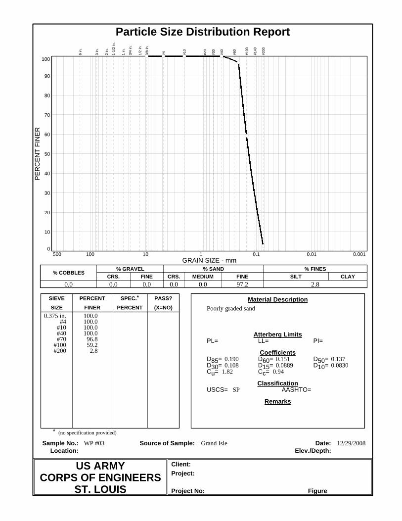
(X=NO)PERCENTFINERSIZEPASS?SPEC.*PERCENTSIEVE
Project No:
Project:Client:
Elev./Depth:Location:Date:Source of Sample:Sample No.:
Remarks
Classification
Coefficients
Atterberg Limits
Material Description
*
AASHTO=USCS=
Cc=Cu=D10=D15=D30=D50=D60=D85=
PI=LL=PL=
Particle Size Distribution Report
10
20
30
40
50
60
70
80
90
0
100
PE
RC
EN
T FI
NE
R
100 10 1 0.1 0.01 0.001500GRAIN SIZE - mm
% COBBLES% GRAVEL
CRS. FINE% SAND
CRS. MEDIUM FINE% FINES
SILT CLAY
6 in
.
3 in
.
2 in
.
1-1/
2 in
.
1 in
.
3/4
in.
1/2
in.
3/8
in.
#4 #10
#20
#30
#40
#60
#100
#140
#200
0.0 0.0 0.0 0.0 0.0 97.2 2.8
Figure
12/29/2008Grand IsleWP #03
SP
0.941.820.08300.08890.1080.1370.1510.190
Poorly graded sand
(no specification provided)
US ARMYCORPS OF ENGINEERS
ST. LOUIS
100.0100.0100.0100.0
96.859.2
2.8
0.375 in.#4
#10#40#70
#100#200

(X=NO)PERCENTFINERSIZEPASS?SPEC.*PERCENTSIEVE
Project No:
Project:Client:
Elev./Depth:Location:Date:Source of Sample:Sample No.:
Remarks
Classification
Coefficients
Atterberg Limits
Material Description
*
AASHTO=USCS=
Cc=Cu=D10=D15=D30=D50=D60=D85=
PI=LL=PL=
Particle Size Distribution Report
10
20
30
40
50
60
70
80
90
0
100
PE
RC
EN
T FI
NE
R
100 10 1 0.1 0.01 0.001500GRAIN SIZE - mm
% COBBLES% GRAVEL
CRS. FINE% SAND
CRS. MEDIUM FINE% FINES
SILT CLAY
6 in
.
3 in
.
2 in
.
1-1/
2 in
.
1 in
.
3/4
in.
1/2
in.
3/8
in.
#4 #10
#20
#30
#40
#60
#100
#140
#200
0.0 0.0 0.0 0.0 0.0 96.0 4.0
Figure
12/29/2008Grand IsleWP #04
SP
0.971.870.08280.08970.1120.1410.1550.191
Poorly graded sand
(no specification provided)
US ARMYCORPS OF ENGINEERS
ST. LOUIS
100.0100.0100.0100.0
97.156.5
4.0
0.375 in.#4
#10#40#70
#100#200

(X=NO)PERCENTFINERSIZEPASS?SPEC.*PERCENTSIEVE
Project No:
Project:Client:
Elev./Depth:Location:Date:Source of Sample:Sample No.:
Remarks
Classification
Coefficients
Atterberg Limits
Material Description
*
AASHTO=USCS=
Cc=Cu=D10=D15=D30=D50=D60=D85=
PI=LL=PL=
Particle Size Distribution Report
10
20
30
40
50
60
70
80
90
0
100
PE
RC
EN
T FI
NE
R
100 10 1 0.1 0.01 0.001500GRAIN SIZE - mm
% COBBLES% GRAVEL
CRS. FINE% SAND
CRS. MEDIUM FINE% FINES
SILT CLAY
6 in
.
3 in
.
2 in
.
1-1/
2 in
.
1 in
.
3/4
in.
1/2
in.
3/8
in.
#4 #10
#20
#30
#40
#60
#100
#140
#200
0.0 0.0 0.0 0.0 1.0 95.5 3.5
Figure
12/29/2008Grand IsleWP #05
SP
1.021.920.08600.09480.1200.1510.1650.201
Poorly graded sand
(no specification provided)
US ARMYCORPS OF ENGINEERS
ST. LOUIS
100.0100.0100.0
99.090.949.4
3.5
0.375 in.#4
#10#40#70
#100#200
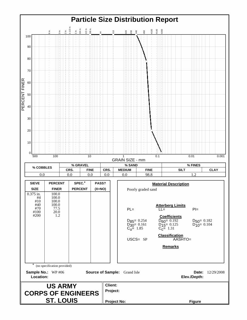
(X=NO)PERCENTFINERSIZEPASS?SPEC.*PERCENTSIEVE
Project No:
Project:Client:
Elev./Depth:Location:Date:Source of Sample:Sample No.:
Remarks
Classification
Coefficients
Atterberg Limits
Material Description
*
AASHTO=USCS=
Cc=Cu=D10=D15=D30=D50=D60=D85=
PI=LL=PL=
Particle Size Distribution Report
10
20
30
40
50
60
70
80
90
0
100
PE
RC
EN
T FI
NE
R
100 10 1 0.1 0.01 0.001500GRAIN SIZE - mm
% COBBLES% GRAVEL
CRS. FINE% SAND
CRS. MEDIUM FINE% FINES
SILT CLAY
6 in
.
3 in
.
2 in
.
1-1/
2 in
.
1 in
.
3/4
in.
1/2
in.
3/8
in.
#4 #10
#20
#30
#40
#60
#100
#140
#200
0.0 0.0 0.0 0.0 0.0 98.8 1.2
Figure
12/29/2008Grand IsleWP #06
SP
1.311.850.1040.1250.1610.1820.1920.254
Poorly graded sand
(no specification provided)
US ARMYCORPS OF ENGINEERS
ST. LOUIS
100.0100.0100.0100.0
77.520.0
1.2
0.375 in.#4
#10#40#70
#100#200

(X=NO)PERCENTFINERSIZEPASS?SPEC.*PERCENTSIEVE
Project No:
Project:Client:
Elev./Depth:Location:Date:Source of Sample:Sample No.:
Remarks
Classification
Coefficients
Atterberg Limits
Material Description
*
AASHTO=USCS=
Cc=Cu=D10=D15=D30=D50=D60=D85=
PI=LL=PL=
Particle Size Distribution Report
10
20
30
40
50
60
70
80
90
0
100
PE
RC
EN
T FI
NE
R
100 10 1 0.1 0.01 0.001500GRAIN SIZE - mm
% COBBLES% GRAVEL
CRS. FINE% SAND
CRS. MEDIUM FINE% FINES
SILT CLAY
6 in
.
3 in
.
2 in
.
1-1/
2 in
.
1 in
.
3/4
in.
1/2
in.
3/8
in.
#4 #10
#20
#30
#40
#60
#100
#140
#200
0.0 0.0 0.0 0.0 0.0 98.9 1.1
Figure
12/29/2008Grand IsleWP #07
SP
1.311.950.09230.1040.1470.1700.1800.204
Poorly graded sand
(no specification provided)
US ARMYCORPS OF ENGINEERS
ST. LOUIS
100.0100.0100.0100.0
90.330.8
1.1
0.375 in.#4
#10#40#70
#100#200

(X=NO)PERCENTFINERSIZEPASS?SPEC.*PERCENTSIEVE
Project No:
Project:Client:
Elev./Depth:Location:Date:Source of Sample:Sample No.:
Remarks
Classification
Coefficients
Atterberg Limits
Material Description
*
AASHTO=USCS=
Cc=Cu=D10=D15=D30=D50=D60=D85=
PI=LL=PL=
Particle Size Distribution Report
10
20
30
40
50
60
70
80
90
0
100
PE
RC
EN
T FI
NE
R
100 10 1 0.1 0.01 0.001500GRAIN SIZE - mm
% COBBLES% GRAVEL
CRS. FINE% SAND
CRS. MEDIUM FINE% FINES
SILT CLAY
6 in
.
3 in
.
2 in
.
1-1/
2 in
.
1 in
.
3/4
in.
1/2
in.
3/8
in.
#4 #10
#20
#30
#40
#60
#100
#140
#200
0.0 0.0 0.0 0.0 0.0 98.9 1.1
Figure
12/29/2008Grand IsleWP #08
SP
1.371.890.09360.1060.1510.1690.1770.198
Poorly graded sand
(no specification provided)
US ARMYCORPS OF ENGINEERS
ST. LOUIS
100.0100.0100.0100.0
98.128.9
1.1
0.375 in.#4
#10#40#70
#100#200

(X=NO)PERCENTFINERSIZEPASS?SPEC.*PERCENTSIEVE
Project No:
Project:Client:
Elev./Depth:Location:Date:Source of Sample:Sample No.:
Remarks
Classification
Coefficients
Atterberg Limits
Material Description
*
AASHTO=USCS=
Cc=Cu=D10=D15=D30=D50=D60=D85=
PI=LL=PL=
Particle Size Distribution Report
10
20
30
40
50
60
70
80
90
0
100
PE
RC
EN
T FI
NE
R
100 10 1 0.1 0.01 0.001500GRAIN SIZE - mm
% COBBLES% GRAVEL
CRS. FINE% SAND
CRS. MEDIUM FINE% FINES
SILT CLAY
6 in
.
3 in
.
2 in
.
1-1/
2 in
.
1 in
.
3/4
in.
1/2
in.
3/8
in.
#4 #10
#20
#30
#40
#60
#100
#140
#200
0.0 0.0 0.0 0.0 0.0 96.2 3.8
Figure
12/29/2008Grand IsleWP #09
SP
1.061.880.08690.09660.1220.1510.1630.194
Poorly graded sand
(no specification provided)
US ARMYCORPS OF ENGINEERS
ST. LOUIS
100.0100.0100.0100.0
96.949.6
3.8
0.375 in.#4
#10#40#70
#100#200

(X=NO)PERCENTFINERSIZEPASS?SPEC.*PERCENTSIEVE
Project No:
Project:Client:
Elev./Depth:Location:Date:Source of Sample:Sample No.:
Remarks
Classification
Coefficients
Atterberg Limits
Material Description
*
AASHTO=USCS=
Cc=Cu=D10=D15=D30=D50=D60=D85=
PI=LL=PL=
Particle Size Distribution Report
10
20
30
40
50
60
70
80
90
0
100
PE
RC
EN
T FI
NE
R
100 10 1 0.1 0.01 0.001500GRAIN SIZE - mm
% COBBLES% GRAVEL
CRS. FINE% SAND
CRS. MEDIUM FINE% FINES
SILT CLAY
6 in
.
3 in
.
2 in
.
1-1/
2 in
.
1 in
.
3/4
in.
1/2
in.
3/8
in.
#4 #10
#20
#30
#40
#60
#100
#140
#200
0.0 0.0 0.0 0.0 0.0 93.0 7.0
Figure
12/29/2008Grand IsleWP #10
SP-SM
0.891.650.07720.08100.09360.1140.1270.173
Poorly graded sand with silt
(no specification provided)
US ARMYCORPS OF ENGINEERS
ST. LOUIS
100.0100.0100.0100.0
98.974.2
7.0
0.375 in.#4
#10#40#70
#100#200

(X=NO)PERCENTFINERSIZEPASS?SPEC.*PERCENTSIEVE
Project No:
Project:Client:
Elev./Depth:Location:Date:Source of Sample:Sample No.:
Remarks
Classification
Coefficients
Atterberg Limits
Material Description
*
AASHTO=USCS=
Cc=Cu=D10=D15=D30=D50=D60=D85=
PI=LL=PL=
Particle Size Distribution Report
10
20
30
40
50
60
70
80
90
0
100
PE
RC
EN
T FI
NE
R
100 10 1 0.1 0.01 0.001500GRAIN SIZE - mm
% COBBLES% GRAVEL
CRS. FINE% SAND
CRS. MEDIUM FINE% FINES
SILT CLAY
6 in
.
3 in
.
2 in
.
1-1/
2 in
.
1 in
.
3/4
in.
1/2
in.
3/8
in.
#4 #10
#20
#30
#40
#60
#100
#140
#200
0.0 0.0 0.0 0.0 0.0 97.7 2.3
Figure
12/29/2008Grand IsleWP #11
SP
1.261.980.08950.1000.1420.1680.1770.201
Poorly graded sand
(no specification provided)
US ARMYCORPS OF ENGINEERS
ST. LOUIS
100.0100.0100.0100.0
93.432.5
2.3
0.375 in.#4
#10#40#70
#100#200

(X=NO)PERCENTFINERSIZEPASS?SPEC.*PERCENTSIEVE
Project No:
Project:Client:
Elev./Depth:Location:Date:Source of Sample:Sample No.:
Remarks
Classification
Coefficients
Atterberg Limits
Material Description
*
AASHTO=USCS=
Cc=Cu=D10=D15=D30=D50=D60=D85=
PI=LL=PL=
Particle Size Distribution Report
10
20
30
40
50
60
70
80
90
0
100
PE
RC
EN
T FI
NE
R
100 10 1 0.1 0.01 0.001500GRAIN SIZE - mm
% COBBLES% GRAVEL
CRS. FINE% SAND
CRS. MEDIUM FINE% FINES
SILT CLAY
6 in
.
3 in
.
2 in
.
1-1/
2 in
.
1 in
.
3/4
in.
1/2
in.
3/8
in.
#4 #10
#20
#30
#40
#60
#100
#140
#200
0.0 0.0 0.0 0.0 0.0 93.6 6.4
Figure
12/29/2008Grand IsleWP #12
SP-SM
0.891.730.07800.08230.09680.1200.1350.179
Poorly graded sand with silt
(no specification provided)
US ARMYCORPS OF ENGINEERS
ST. LOUIS
100.0100.0100.0100.0
99.169.7
6.4
0.375 in.#4
#10#40#70
#100#200

(X=NO)PERCENTFINERSIZEPASS?SPEC.*PERCENTSIEVE
Project No:
Project:Client:
Elev./Depth:Location:Date:Source of Sample:Sample No.:
Remarks
Classification
Coefficients
Atterberg Limits
Material Description
*
AASHTO=USCS=
Cc=Cu=D10=D15=D30=D50=D60=D85=
PI=LL=PL=
Particle Size Distribution Report
10
20
30
40
50
60
70
80
90
0
100
PE
RC
EN
T FI
NE
R
100 10 1 0.1 0.01 0.001500GRAIN SIZE - mm
% COBBLES% GRAVEL
CRS. FINE% SAND
CRS. MEDIUM FINE% FINES
SILT CLAY
6 in
.
3 in
.
2 in
.
1-1/
2 in
.
1 in
.
3/4
in.
1/2
in.
3/8
in.
#4 #10
#20
#30
#40
#60
#100
#140
#200
0.0 0.0 0.0 0.0 0.0 94.9 5.1
Figure
12/29/2008Grand IsleWP #13
SP-SM
0.901.730.07920.08360.09860.1230.1370.180
Poorly graded sand with silt
(no specification provided)
US ARMYCORPS OF ENGINEERS
ST. LOUIS
100.0100.0100.0100.0
99.068.2
5.1
0.375 in.#4
#10#40#70
#100#200

(X=NO)PERCENTFINERSIZEPASS?SPEC.*PERCENTSIEVE
Project No:
Project:Client:
Elev./Depth:Location:Date:Source of Sample:Sample No.:
Remarks
Classification
Coefficients
Atterberg Limits
Material Description
*
AASHTO=USCS=
Cc=Cu=D10=D15=D30=D50=D60=D85=
PI=LL=PL=
Particle Size Distribution Report
10
20
30
40
50
60
70
80
90
0
100
PE
RC
EN
T FI
NE
R
100 10 1 0.1 0.01 0.001500GRAIN SIZE - mm
% COBBLES% GRAVEL
CRS. FINE% SAND
CRS. MEDIUM FINE% FINES
SILT CLAY
6 in
.
3 in
.
2 in
.
1-1/
2 in
.
1 in
.
3/4
in.
1/2
in.
3/8
in.
#4 #10
#20
#30
#40
#60
#100
#140
#200
0.0 0.0 0.0 0.0 0.0 97.2 2.8
Figure
12/29/2008Grand IsleWP #14
SP
1.041.840.08770.09670.1210.1490.1620.193
Poorly graded sand
(no specification provided)
US ARMYCORPS OF ENGINEERS
ST. LOUIS
100.0100.0100.0100.0
98.250.7
2.8
0.375 in.#4
#10#40#70
#100#200

(X=NO)PERCENTFINERSIZEPASS?SPEC.*PERCENTSIEVE
Project No:
Project:Client:
Elev./Depth:Location:Date:Source of Sample:Sample No.:
Remarks
Classification
Coefficients
Atterberg Limits
Material Description
*
AASHTO=USCS=
Cc=Cu=D10=D15=D30=D50=D60=D85=
PI=LL=PL=
Particle Size Distribution Report
10
20
30
40
50
60
70
80
90
0
100
PE
RC
EN
T FI
NE
R
100 10 1 0.1 0.01 0.001500GRAIN SIZE - mm
% COBBLES% GRAVEL
CRS. FINE% SAND
CRS. MEDIUM FINE% FINES
SILT CLAY
6 in
.
3 in
.
2 in
.
1-1/
2 in
.
1 in
.
3/4
in.
1/2
in.
3/8
in.
#4 #10
#20
#30
#40
#60
#100
#140
#200
0.0 0.0 0.0 0.0 0.0 90.3 9.7
Figure
12/29/2008Grand IsleWP #15
SP-SM
0.911.910.07530.08080.09940.1280.1440.186
Poorly graded sand with silt
(no specification provided)
US ARMYCORPS OF ENGINEERS
ST. LOUIS
100.0100.0100.0100.0
97.263.8
9.7
0.375 in.#4
#10#40#70
#100#200

(X=NO)PERCENTFINERSIZEPASS?SPEC.*PERCENTSIEVE
Project No:
Project:Client:
Elev./Depth:Location:Date:Source of Sample:Sample No.:
Remarks
Classification
Coefficients
Atterberg Limits
Material Description
*
AASHTO=USCS=
Cc=Cu=D10=D15=D30=D50=D60=D85=
PI=LL=PL=
Particle Size Distribution Report
10
20
30
40
50
60
70
80
90
0
100
PE
RC
EN
T FI
NE
R
100 10 1 0.1 0.01 0.001500GRAIN SIZE - mm
% COBBLES% GRAVEL
CRS. FINE% SAND
CRS. MEDIUM FINE% FINES
SILT CLAY
6 in
.
3 in
.
2 in
.
1-1/
2 in
.
1 in
.
3/4
in.
1/2
in.
3/8
in.
#4 #10
#20
#30
#40
#60
#100
#140
#200
0.0 0.0 0.0 0.0 0.0 97.5 2.5
Figure
12/29/2008Grand IsleWP #16
SP
1.411.950.09110.1040.1510.1690.1780.199
Poorly graded sand
(no specification provided)
US ARMYCORPS OF ENGINEERS
ST. LOUIS
100.0100.0100.0100.0
97.429.2
2.5
0.375 in.#4
#10#40#70
#100#200

(X=NO)PERCENTFINERSIZEPASS?SPEC.*PERCENTSIEVE
Project No:
Project:Client:
Elev./Depth:Location:Date:Source of Sample:Sample No.:
Remarks
Classification
Coefficients
Atterberg Limits
Material Description
*
AASHTO=USCS=
Cc=Cu=D10=D15=D30=D50=D60=D85=
PI=LL=PL=
Particle Size Distribution Report
10
20
30
40
50
60
70
80
90
0
100
PE
RC
EN
T FI
NE
R
100 10 1 0.1 0.01 0.001500GRAIN SIZE - mm
% COBBLES% GRAVEL
CRS. FINE% SAND
CRS. MEDIUM FINE% FINES
SILT CLAY
6 in
.
3 in
.
2 in
.
1-1/
2 in
.
1 in
.
3/4
in.
1/2
in.
3/8
in.
#4 #10
#20
#30
#40
#60
#100
#140
#200
0.0 0.0 0.0 0.0 0.0 99.1 0.9
Figure
12/29/2008Grand IsleWP #17
SP
1.061.640.1040.1140.1370.1600.1700.196
Poorly graded sand
(no specification provided)
US ARMYCORPS OF ENGINEERS
ST. LOUIS
100.0100.0100.0100.0
98.241.0
0.9
0.375 in.#4
#10#40#70
#100#200

(X=NO)PERCENTFINERSIZEPASS?SPEC.*PERCENTSIEVE
Project No:
Project:Client:
Elev./Depth:Location:Date:Source of Sample:Sample No.:
Remarks
Classification
Coefficients
Atterberg Limits
Material Description
*
AASHTO=USCS=
Cc=Cu=D10=D15=D30=D50=D60=D85=
PI=LL=PL=
Particle Size Distribution Report
10
20
30
40
50
60
70
80
90
0
100
PE
RC
EN
T FI
NE
R
100 10 1 0.1 0.01 0.001500GRAIN SIZE - mm
% COBBLES% GRAVEL
CRS. FINE% SAND
CRS. MEDIUM FINE% FINES
SILT CLAY
6 in
.
3 in
.
2 in
.
1-1/
2 in
.
1 in
.
3/4
in.
1/2
in.
3/8
in.
#4 #10
#20
#30
#40
#60
#100
#140
#200
0.0 0.0 0.0 0.0 0.0 98.8 1.2
Figure
12/29/2008Grand IsleWP #18
SP
1.071.730.09680.1070.1320.1560.1680.195
Poorly graded sand
(no specification provided)
US ARMYCORPS OF ENGINEERS
ST. LOUIS
100.0100.0100.0100.0
97.644.4
1.2
0.375 in.#4
#10#40#70
#100#200

(X=NO)PERCENTFINERSIZEPASS?SPEC.*PERCENTSIEVE
Project No:
Project:Client:
Elev./Depth:Location:Date:Source of Sample:Sample No.:
Remarks
Classification
Coefficients
Atterberg Limits
Material Description
*
AASHTO=USCS=
Cc=Cu=D10=D15=D30=D50=D60=D85=
PI=LL=PL=
Particle Size Distribution Report
10
20
30
40
50
60
70
80
90
0
100
PE
RC
EN
T FI
NE
R
100 10 1 0.1 0.01 0.001500GRAIN SIZE - mm
% COBBLES% GRAVEL
CRS. FINE% SAND
CRS. MEDIUM FINE% FINES
SILT CLAY
6 in
.
3 in
.
2 in
.
1-1/
2 in
.
1 in
.
3/4
in.
1/2
in.
3/8
in.
#4 #10
#20
#30
#40
#60
#100
#140
#200
0.0 0.0 0.0 0.0 0.0 99.3 0.7
Figure
12/29/2008Grand IsleWP #19
SP
1.061.630.1040.1140.1370.1600.1700.196
Poorly graded sand
(no specification provided)
US ARMYCORPS OF ENGINEERS
ST. LOUIS
100.0100.0100.0100.0
98.440.8
0.7
0.375 in.#4
#10#40#70
#100#200

(X=NO)PERCENTFINERSIZEPASS?SPEC.*PERCENTSIEVE
Project No:
Project:Client:
Elev./Depth:Location:Date:Source of Sample:Sample No.:
Remarks
Classification
Coefficients
Atterberg Limits
Material Description
*
AASHTO=USCS=
Cc=Cu=D10=D15=D30=D50=D60=D85=
PI=LL=PL=
Particle Size Distribution Report
10
20
30
40
50
60
70
80
90
0
100
PE
RC
EN
T FI
NE
R
100 10 1 0.1 0.01 0.001500GRAIN SIZE - mm
% COBBLES% GRAVEL
CRS. FINE% SAND
CRS. MEDIUM FINE% FINES
SILT CLAY
6 in
.
3 in
.
2 in
.
1-1/
2 in
.
1 in
.
3/4
in.
1/2
in.
3/8
in.
#4 #10
#20
#30
#40
#60
#100
#140
#200
0.0 0.0 0.0 0.0 0.0 98.9 1.1
Figure
12/29/2008Grand IsleWP #20
SP
1.061.630.1050.1150.1370.1600.1700.196
Poorly graded sand
(no specification provided)
US ARMYCORPS OF ENGINEERS
ST. LOUIS
100.0100.0100.0100.0
98.540.5
1.1
0.375 in.#4
#10#40#70
#100#200

(X=NO)PERCENTFINERSIZEPASS?SPEC.*PERCENTSIEVE
Project No:
Project:Client:
Elev./Depth:Location:Date:Source of Sample:Sample No.:
Remarks
Classification
Coefficients
Atterberg Limits
Material Description
*
AASHTO=USCS=
Cc=Cu=D10=D15=D30=D50=D60=D85=
PI=LL=PL=
Particle Size Distribution Report
10
20
30
40
50
60
70
80
90
0
100
PE
RC
EN
T FI
NE
R
100 10 1 0.1 0.01 0.001500GRAIN SIZE - mm
% COBBLES% GRAVEL
CRS. FINE% SAND
CRS. MEDIUM FINE% FINES
SILT CLAY
6 in
.
3 in
.
2 in
.
1-1/
2 in
.
1 in
.
3/4
in.
1/2
in.
3/8
in.
#4 #10
#20
#30
#40
#60
#100
#140
#200
0.0 0.0 0.0 0.0 0.0 98.0 2.0
Figure
12/29/2008Grand IsleWP #21
SP
1.071.630.1040.1150.1380.1600.1700.195
Poorly graded sand
(no specification provided)
US ARMYCORPS OF ENGINEERS
ST. LOUIS
100.0100.0100.0100.0
99.140.4
2.0
0.375 in.#4
#10#40#70
#100#200

(X=NO)PERCENTFINERSIZEPASS?SPEC.*PERCENTSIEVE
Project No:
Project:Client:
Elev./Depth:Location:Date:Source of Sample:Sample No.:
Remarks
Classification
Coefficients
Atterberg Limits
Material Description
*
AASHTO=USCS=
Cc=Cu=D10=D15=D30=D50=D60=D85=
PI=LL=PL=
Particle Size Distribution Report
10
20
30
40
50
60
70
80
90
0
100
PE
RC
EN
T FI
NE
R
100 10 1 0.1 0.01 0.001500GRAIN SIZE - mm
% COBBLES% GRAVEL
CRS. FINE% SAND
CRS. MEDIUM FINE% FINES
SILT CLAY
6 in
.
3 in
.
2 in
.
1-1/
2 in
.
1 in
.
3/4
in.
1/2
in.
3/8
in.
#4 #10
#20
#30
#40
#60
#100
#140
#200
0.0 0.0 0.0 0.0 0.0 97.2 2.8
Figure
Grand IsleWP #22
SP
1.071.660.1060.1170.1410.1650.1760.204
Poorly graded sand
(no specification provided)
US ARMYCORPS OF ENGINEERS
ST. LOUIS
100.0100.0100.0100.0
90.236.7
2.8
0.375 in.#4
#10#40#70
#100#200

(X=NO)PERCENTFINERSIZEPASS?SPEC.*PERCENTSIEVE
Project No:
Project:Client:
Elev./Depth:Location:Date:Source of Sample:Sample No.:
Remarks
Classification
Coefficients
Atterberg Limits
Material Description
*
AASHTO=USCS=
Cc=Cu=D10=D15=D30=D50=D60=D85=
PI=LL=PL=
Particle Size Distribution Report
10
20
30
40
50
60
70
80
90
0
100
PE
RC
EN
T FI
NE
R
100 10 1 0.1 0.01 0.001500GRAIN SIZE - mm
% COBBLES% GRAVEL
CRS. FINE% SAND
CRS. MEDIUM FINE% FINES
SILT CLAY
6 in
.
3 in
.
2 in
.
1-1/
2 in
.
1 in
.
3/4
in.
1/2
in.
3/8
in.
#4 #10
#20
#30
#40
#60
#100
#140
#200
0.0 0.0 0.0 0.0 0.0 99.7 0.3
Figure
12/29/2008Grand IsleWP #23
SP
1.331.840.09970.1150.1560.1750.1830.206
Poorly graded sand
(no specification provided)
US ARMYCORPS OF ENGINEERS
ST. LOUIS
100.0100.0100.0100.0
89.223.9
0.3
0.375 in.#4
#10#40#70
#100#200

(X=NO)PERCENTFINERSIZEPASS?SPEC.*PERCENTSIEVE
Project No:
Project:Client:
Elev./Depth:Location:Date:Source of Sample:Sample No.:
Remarks
Classification
Coefficients
Atterberg Limits
Material Description
*
AASHTO=USCS=
Cc=Cu=D10=D15=D30=D50=D60=D85=
PI=LL=PL=
Particle Size Distribution Report
10
20
30
40
50
60
70
80
90
0
100
PE
RC
EN
T FI
NE
R
100 10 1 0.1 0.01 0.001500GRAIN SIZE - mm
% COBBLES% GRAVEL
CRS. FINE% SAND
CRS. MEDIUM FINE% FINES
SILT CLAY
6 in
.
3 in
.
2 in
.
1-1/
2 in
.
1 in
.
3/4
in.
1/2
in.
3/8
in.
#4 #10
#20
#30
#40
#60
#100
#140
#200
0.0 0.0 0.0 0.0 0.0 97.2 2.8
Figure
12/29/2008Grand IsleWP #24
SP
1.391.970.08990.1020.1490.1680.1770.199
Poorly graded sand
(no specification provided)
US ARMYCORPS OF ENGINEERS
ST. LOUIS
100.0100.0100.0100.0
97.730.3
2.8
0.375 in.#4
#10#40#70
#100#200

(X=NO)PERCENTFINERSIZEPASS?SPEC.*PERCENTSIEVE
Project No:
Project:Client:
Elev./Depth:Location:Date:Source of Sample:Sample No.:
Remarks
Classification
Coefficients
Atterberg Limits
Material Description
*
AASHTO=USCS=
Cc=Cu=D10=D15=D30=D50=D60=D85=
PI=LL=PL=
Particle Size Distribution Report
10
20
30
40
50
60
70
80
90
0
100
PE
RC
EN
T FI
NE
R
100 10 1 0.1 0.01 0.001500GRAIN SIZE - mm
% COBBLES% GRAVEL
CRS. FINE% SAND
CRS. MEDIUM FINE% FINES
SILT CLAY
6 in
.
3 in
.
2 in
.
1-1/
2 in
.
1 in
.
3/4
in.
1/2
in.
3/8
in.
#4 #10
#20
#30
#40
#60
#100
#140
#200
0.0 0.0 0.0 0.0 0.0 98.7 1.3
Figure
12/29/2008Grand IsleWP #25
SP
1.361.930.09370.1060.1520.1720.1810.205
Poorly graded sand
(no specification provided)
US ARMYCORPS OF ENGINEERS
ST. LOUIS
100.0100.0100.0100.0
89.728.4
1.3
0.375 in.#4
#10#40#70
#100#200

(X=NO)PERCENTFINERSIZEPASS?SPEC.*PERCENTSIEVE
Project No:
Project:Client:
Elev./Depth:Location:Date:Source of Sample:Sample No.:
Remarks
Classification
Coefficients
Atterberg Limits
Material Description
*
AASHTO=USCS=
Cc=Cu=D10=D15=D30=D50=D60=D85=
PI=LL=PL=
Particle Size Distribution Report
10
20
30
40
50
60
70
80
90
0
100
PE
RC
EN
T FI
NE
R
100 10 1 0.1 0.01 0.001500GRAIN SIZE - mm
% COBBLES% GRAVEL
CRS. FINE% SAND
CRS. MEDIUM FINE% FINES
SILT CLAY
6 in
.
3 in
.
2 in
.
1-1/
2 in
.
1 in
.
3/4
in.
1/2
in.
3/8
in.
#4 #10
#20
#30
#40
#60
#100
#140
#200
0.0 0.0 0.0 0.0 0.0 98.0 2.0
Figure
12/29/2008Grand IsleWP #26
SP
1.391.930.09340.1070.1530.1710.1800.203
Poorly graded sand
(no specification provided)
US ARMYCORPS OF ENGINEERS
ST. LOUIS
100.0100.0100.0100.0
92.827.3
2.0
0.375 in.#4
#10#40#70
#100#200

(X=NO)PERCENTFINERSIZEPASS?SPEC.*PERCENTSIEVE
Project No:
Project:Client:
Elev./Depth:Location:Date:Source of Sample:Sample No.:
Remarks
Classification
Coefficients
Atterberg Limits
Material Description
*
AASHTO=USCS=
Cc=Cu=D10=D15=D30=D50=D60=D85=
PI=LL=PL=
Particle Size Distribution Report
10
20
30
40
50
60
70
80
90
0
100
PE
RC
EN
T FI
NE
R
100 10 1 0.1 0.01 0.001500GRAIN SIZE - mm
% COBBLES% GRAVEL
CRS. FINE% SAND
CRS. MEDIUM FINE% FINES
SILT CLAY
6 in
.
3 in
.
2 in
.
1-1/
2 in
.
1 in
.
3/4
in.
1/2
in.
3/8
in.
#4 #10
#20
#30
#40
#60
#100
#140
#200
0.0 0.0 0.0 0.0 0.0 99.0 1.0
Figure
12/29/2008Grand IsleWP #27
SP
1.361.910.09340.1060.1510.1690.1780.200
Poorly graded sand
(no specification provided)
US ARMYCORPS OF ENGINEERS
ST. LOUIS
100.0100.0100.0100.0
95.429.4
1.0
0.375 in.#4
#10#40#70
#100#200

(X=NO)PERCENTFINERSIZEPASS?SPEC.*PERCENTSIEVE
Project No:
Project:Client:
Elev./Depth:Location:Date:Source of Sample:Sample No.:
Remarks
Classification
Coefficients
Atterberg Limits
Material Description
*
AASHTO=USCS=
Cc=Cu=D10=D15=D30=D50=D60=D85=
PI=LL=PL=
Particle Size Distribution Report
10
20
30
40
50
60
70
80
90
0
100
PE
RC
EN
T FI
NE
R
100 10 1 0.1 0.01 0.001500GRAIN SIZE - mm
% COBBLES% GRAVEL
CRS. FINE% SAND
CRS. MEDIUM FINE% FINES
SILT CLAY
6 in
.
3 in
.
2 in
.
1-1/
2 in
.
1 in
.
3/4
in.
1/2
in.
3/8
in.
#4 #10
#20
#30
#40
#60
#100
#140
#200
0.0 0.0 0.0 0.0 0.0 99.6 0.4
Figure
12/29/2008Grand IsleWP #28
SP
1.291.750.1070.1290.1610.1780.1870.209
Poorly graded sand
(no specification provided)
US ARMYCORPS OF ENGINEERS
ST. LOUIS
100.0100.0100.0100.0
85.619.1
0.4
0.375 in.#4
#10#40#70
#100#200

(X=NO)PERCENTFINERSIZEPASS?SPEC.*PERCENTSIEVE
Project No:
Project:Client:
Elev./Depth:Location:Date:Source of Sample:Sample No.:
Remarks
Classification
Coefficients
Atterberg Limits
Material Description
*
AASHTO=USCS=
Cc=Cu=D10=D15=D30=D50=D60=D85=
PI=LL=PL=
Particle Size Distribution Report
10
20
30
40
50
60
70
80
90
0
100
PE
RC
EN
T FI
NE
R
100 10 1 0.1 0.01 0.001500GRAIN SIZE - mm
% COBBLES% GRAVEL
CRS. FINE% SAND
CRS. MEDIUM FINE% FINES
SILT CLAY
6 in
.
3 in
.
2 in
.
1-1/
2 in
.
1 in
.
3/4
in.
1/2
in.
3/8
in.
#4 #10
#20
#30
#40
#60
#100
#140
#200
0.0 0.0 0.0 0.0 0.0 99.5 0.5
Figure
12/29/2008Grand IsleWP #29
SP
1.041.950.1040.1160.1470.1820.2020.289
Poorly graded sand
(no specification provided)
US ARMYCORPS OF ENGINEERS
ST. LOUIS
100.0100.0100.0100.0
63.631.6
0.5
0.375 in.#4
#10#40#70
#100#200

(X=NO)PERCENTFINERSIZEPASS?SPEC.*PERCENTSIEVE
Project No:
Project:Client:
Elev./Depth:Location:Date:Source of Sample:Sample No.:
Remarks
Classification
Coefficients
Atterberg Limits
Material Description
*
AASHTO=USCS=
Cc=Cu=D10=D15=D30=D50=D60=D85=
PI=LL=PL=
Particle Size Distribution Report
10
20
30
40
50
60
70
80
90
0
100
PE
RC
EN
T FI
NE
R
100 10 1 0.1 0.01 0.001500GRAIN SIZE - mm
% COBBLES% GRAVEL
CRS. FINE% SAND
CRS. MEDIUM FINE% FINES
SILT CLAY
6 in
.
3 in
.
2 in
.
1-1/
2 in
.
1 in
.
3/4
in.
1/2
in.
3/8
in.
#4 #10
#20
#30
#40
#60
#100
#140
#200
0.0 0.0 0.0 0.0 0.0 98.9 1.1
Figure
12/29/2008Grand IsleWP #30
SP
1.331.910.09950.1170.1580.1790.1900.249
Poorly graded sand
(no specification provided)
US ARMYCORPS OF ENGINEERS
ST. LOUIS
100.0100.0100.0100.0
78.722.9
1.1
0.375 in.#4
#10#40#70
#100#200

(X=NO)PERCENTFINERSIZEPASS?SPEC.*PERCENTSIEVE
Project No:
Project:Client:
Elev./Depth:Location:Date:Source of Sample:Sample No.:
Remarks
Classification
Coefficients
Atterberg Limits
Material Description
*
AASHTO=USCS=
Cc=Cu=D10=D15=D30=D50=D60=D85=
PI=LL=PL=
Particle Size Distribution Report
10
20
30
40
50
60
70
80
90
0
100
PE
RC
EN
T FI
NE
R
100 10 1 0.1 0.01 0.001500GRAIN SIZE - mm
% COBBLES% GRAVEL
CRS. FINE% SAND
CRS. MEDIUM FINE% FINES
SILT CLAY
6 in
.
3 in
.
2 in
.
1-1/
2 in
.
1 in
.
3/4
in.
1/2
in.
3/8
in.
#4 #10
#20
#30
#40
#60
#100
#140
#200
0.0 0.0 0.0 0.0 0.0 98.9 1.1
Figure
12/29/2009Grand IsleWP #31
SP
1.361.890.09550.1090.1530.1720.1810.203
Poorly graded sand
(no specification provided)
US ARMYCORPS OF ENGINEERS
ST. LOUIS
100.0100.0100.0100.0
92.326.6
1.1
0.375 in.#4
#10#40#70
#100#200

(X=NO)PERCENTFINERSIZEPASS?SPEC.*PERCENTSIEVE
Project No:
Project:Client:
Elev./Depth:Location:Date:Source of Sample:Sample No.:
Remarks
Classification
Coefficients
Atterberg Limits
Material Description
*
AASHTO=USCS=
Cc=Cu=D10=D15=D30=D50=D60=D85=
PI=LL=PL=
Particle Size Distribution Report
10
20
30
40
50
60
70
80
90
0
100
PE
RC
EN
T FI
NE
R
100 10 1 0.1 0.01 0.001500GRAIN SIZE - mm
% COBBLES% GRAVEL
CRS. FINE% SAND
CRS. MEDIUM FINE% FINES
SILT CLAY
6 in
.
3 in
.
2 in
.
1-1/
2 in
.
1 in
.
3/4
in.
1/2
in.
3/8
in.
#4 #10
#20
#30
#40
#60
#100
#140
#200
0.0 0.0 0.0 0.0 0.0 98.8 1.2
Figure
12/29/2008Grand IsleWP #32
SP
1.381.890.09420.1070.1520.1700.1780.199
Poorly graded sand
(no specification provided)
US ARMYCORPS OF ENGINEERS
ST. LOUIS
100.0100.0100.0100.0
96.927.9
1.2
0.375 in.#4
#10#40#70
#100#200

(X=NO)PERCENTFINERSIZEPASS?SPEC.*PERCENTSIEVE
Project No:
Project:Client:
Elev./Depth:Location:Date:Source of Sample:Sample No.:
Remarks
Classification
Coefficients
Atterberg Limits
Material Description
*
AASHTO=USCS=
Cc=Cu=D10=D15=D30=D50=D60=D85=
PI=LL=PL=
Particle Size Distribution Report
10
20
30
40
50
60
70
80
90
0
100
PE
RC
EN
T FI
NE
R
100 10 1 0.1 0.01 0.001500GRAIN SIZE - mm
% COBBLES% GRAVEL
CRS. FINE% SAND
CRS. MEDIUM FINE% FINES
SILT CLAY
6 in
.
3 in
.
2 in
.
1-1/
2 in
.
1 in
.
3/4
in.
1/2
in.
3/8
in.
#4 #10
#20
#30
#40
#60
#100
#140
#200
0.0 0.0 0.0 0.0 0.0 98.9 1.1
Figure
12/29/2008Grand IsleWP #33
SP
1.341.930.09670.1110.1550.1760.1860.225
Poorly graded sand
(no specification provided)
US ARMYCORPS OF ENGINEERS
ST. LOUIS
100.0100.0100.0100.0
82.825.4
1.1
0.375 in.#4
#10#40#70
#100#200

(X=NO)PERCENTFINERSIZEPASS?SPEC.*PERCENTSIEVE
Project No:
Project:Client:
Elev./Depth:Location:Date:Source of Sample:Sample No.:
Remarks
Classification
Coefficients
Atterberg Limits
Material Description
*
AASHTO=USCS=
Cc=Cu=D10=D15=D30=D50=D60=D85=
PI=LL=PL=
Particle Size Distribution Report
10
20
30
40
50
60
70
80
90
0
100
PE
RC
EN
T FI
NE
R
100 10 1 0.1 0.01 0.001500GRAIN SIZE - mm
% COBBLES% GRAVEL
CRS. FINE% SAND
CRS. MEDIUM FINE% FINES
SILT CLAY
6 in
.
3 in
.
2 in
.
1-1/
2 in
.
1 in
.
3/4
in.
1/2
in.
3/8
in.
#4 #10
#20
#30
#40
#60
#100
#140
#200
0.0 0.0 0.0 0.0 0.0 99.5 0.5
Figure
12/29/2008Grand IsleWP #34
SP
1.341.840.09960.1160.1560.1740.1830.205
Poorly graded sand
(no specification provided)
US ARMYCORPS OF ENGINEERS
ST. LOUIS
100.0100.0100.0100.0
90.123.7
0.5
0.375 in.#4
#10#40#70
#100#200

(X=NO)PERCENTFINERSIZEPASS?SPEC.*PERCENTSIEVE
Project No:
Project:Client:
Elev./Depth:Location:Date:Source of Sample:Sample No.:
Remarks
Classification
Coefficients
Atterberg Limits
Material Description
*
AASHTO=USCS=
Cc=Cu=D10=D15=D30=D50=D60=D85=
PI=LL=PL=
Particle Size Distribution Report
10
20
30
40
50
60
70
80
90
0
100
PE
RC
EN
T FI
NE
R
100 10 1 0.1 0.01 0.001500GRAIN SIZE - mm
% COBBLES% GRAVEL
CRS. FINE% SAND
CRS. MEDIUM FINE% FINES
SILT CLAY
6 in
.
3 in
.
2 in
.
1-1/
2 in
.
1 in
.
3/4
in.
1/2
in.
3/8
in.
#4 #10
#20
#30
#40
#60
#100
#140
#200
0.0 0.0 0.0 0.0 0.0 98.4 1.6
Figure
12/29/2008Grand IsleWP #35
SP
1.071.730.09670.1070.1320.1570.1680.195
Poorly graded sand
(no specification provided)
US ARMYCORPS OF ENGINEERS
ST. LOUIS
100.0100.0100.0100.0
97.944.3
1.6
0.375 in.#4
#10#40#70
#100#200

(X=NO)PERCENTFINERSIZEPASS?SPEC.*PERCENTSIEVE
Project No:
Project:Client:
Elev./Depth:Location:Date:Source of Sample:Sample No.:
Remarks
Classification
Coefficients
Atterberg Limits
Material Description
*
AASHTO=USCS=
Cc=Cu=D10=D15=D30=D50=D60=D85=
PI=LL=PL=
Particle Size Distribution Report
10
20
30
40
50
60
70
80
90
0
100
PE
RC
EN
T FI
NE
R
100 10 1 0.1 0.01 0.001500GRAIN SIZE - mm
% COBBLES% GRAVEL
CRS. FINE% SAND
CRS. MEDIUM FINE% FINES
SILT CLAY
6 in
.
3 in
.
2 in
.
1-1/
2 in
.
1 in
.
3/4
in.
1/2
in.
3/8
in.
#4 #10
#20
#30
#40
#60
#100
#140
#200
0.0 0.0 0.0 0.0 0.1 98.8 1.1
Figure
12/29/2008Grand IsleWP #36
SP
1.361.830.09900.1160.1560.1730.1810.201
Poorly graded sand
(no specification provided)
US ARMYCORPS OF ENGINEERS
ST. LOUIS
100.0100.0100.0
99.995.523.3
1.1
0.375 in.#4
#10#40#70
#100#200

(X=NO)PERCENTFINERSIZEPASS?SPEC.*PERCENTSIEVE
Project No:
Project:Client:
Elev./Depth:Location:Date:Source of Sample:Sample No.:
Remarks
Classification
Coefficients
Atterberg Limits
Material Description
*
AASHTO=USCS=
Cc=Cu=D10=D15=D30=D50=D60=D85=
PI=LL=PL=
Particle Size Distribution Report
10
20
30
40
50
60
70
80
90
0
100
PE
RC
EN
T FI
NE
R
100 10 1 0.1 0.01 0.001500GRAIN SIZE - mm
% COBBLES% GRAVEL
CRS. FINE% SAND
CRS. MEDIUM FINE% FINES
SILT CLAY
6 in
.
3 in
.
2 in
.
1-1/
2 in
.
1 in
.
3/4
in.
1/2
in.
3/8
in.
#4 #10
#20
#30
#40
#60
#100
#140
#200
0.0 0.0 0.0 0.0 0.0 99.3 0.7
Figure
12/29/2008Grand IsleWP #37
SP
1.361.850.09730.1120.1540.1720.1800.201
Poorly graded sand
(no specification provided)
US ARMYCORPS OF ENGINEERS
ST. LOUIS
100.0100.0100.0100.0
94.925.5
0.7
0.375 in.#4
#10#40#70
#100#200

(X=NO)PERCENTFINERSIZEPASS?SPEC.*PERCENTSIEVE
Project No:
Project:Client:
Elev./Depth:Location:Date:Source of Sample:Sample No.:
Remarks
Classification
Coefficients
Atterberg Limits
Material Description
*
AASHTO=USCS=
Cc=Cu=D10=D15=D30=D50=D60=D85=
PI=LL=PL=
Particle Size Distribution Report
10
20
30
40
50
60
70
80
90
0
100
PE
RC
EN
T FI
NE
R
100 10 1 0.1 0.01 0.001500GRAIN SIZE - mm
% COBBLES% GRAVEL
CRS. FINE% SAND
CRS. MEDIUM FINE% FINES
SILT CLAY
6 in
.
3 in
.
2 in
.
1-1/
2 in
.
1 in
.
3/4
in.
1/2
in.
3/8
in.
#4 #10
#20
#30
#40
#60
#100
#140
#200
0.0 0.0 0.0 0.2 0.4 87.5 11.9
Figure
12/29/Grand IsleWP #38
SP-SM
0.07980.1050.1380.1540.193
Poorly graded sand with silt
(no specification provided)
US ARMYCORPS OF ENGINEERS
ST. LOUIS
100.0100.0
99.899.495.357.611.9
0.375 in.#4
#10#40#70
#100#200

(X=NO)PERCENTFINERSIZEPASS?SPEC.*PERCENTSIEVE
Project No:
Project:Client:
Elev./Depth:Location:Date:Source of Sample:Sample No.:
Remarks
Classification
Coefficients
Atterberg Limits
Material Description
*
AASHTO=USCS=
Cc=Cu=D10=D15=D30=D50=D60=D85=
PI=LL=PL=
Particle Size Distribution Report
10
20
30
40
50
60
70
80
90
0
100
PE
RC
EN
T FI
NE
R
100 10 1 0.1 0.01 0.001500GRAIN SIZE - mm
% COBBLES% GRAVEL
CRS. FINE% SAND
CRS. MEDIUM FINE% FINES
SILT CLAY
6 in
.
3 in
.
2 in
.
1-1/
2 in
.
1 in
.
3/4
in.
1/2
in.
3/8
in.
#4 #10
#20
#30
#40
#60
#100
#140
#200
0.0 0.0 0.0 0.0 0.0 98.5 1.5
Figure
12/30/2008Grand IsleWP #39
SP
1.221.950.09010.1000.1390.1660.1760.199
Poorly graded sand
(no specification provided)
US ARMYCORPS OF ENGINEERS
ST. LOUIS
100.0100.0100.0100.0
95.833.6
1.5
0.375 in.#4
#10#40#70
#100#200

(X=NO)PERCENTFINERSIZEPASS?SPEC.*PERCENTSIEVE
Project No:
Project:Client:
Elev./Depth:Location:Date:Source of Sample:Sample No.:
Remarks
Classification
Coefficients
Atterberg Limits
Material Description
*
AASHTO=USCS=
Cc=Cu=D10=D15=D30=D50=D60=D85=
PI=LL=PL=
Particle Size Distribution Report
10
20
30
40
50
60
70
80
90
0
100
PE
RC
EN
T FI
NE
R
100 10 1 0.1 0.01 0.001500GRAIN SIZE - mm
% COBBLES% GRAVEL
CRS. FINE% SAND
CRS. MEDIUM FINE% FINES
SILT CLAY
6 in
.
3 in
.
2 in
.
1-1/
2 in
.
1 in
.
3/4
in.
1/2
in.
3/8
in.
#4 #10
#20
#30
#40
#60
#100
#140
#200
0.0 0.0 0.0 0.0 0.0 93.8 6.2
Figure
12/20/2008Grand IsleWP #40
SP-SM
1.051.980.08190.09130.1180.1480.1620.195
Poorly graded sand with silt
(no specification provided)
US ARMYCORPS OF ENGINEERS
ST. LOUIS
100.0100.0100.0100.0
95.151.3
6.2
0.375 in.#4
#10#40#70
#100#200

(X=NO)PERCENTFINERSIZEPASS?SPEC.*PERCENTSIEVE
Project No:
Project:Client:
Elev./Depth:Location:Date:Source of Sample:Sample No.:
Remarks
Classification
Coefficients
Atterberg Limits
Material Description
*
AASHTO=USCS=
Cc=Cu=D10=D15=D30=D50=D60=D85=
PI=LL=PL=
Particle Size Distribution Report
10
20
30
40
50
60
70
80
90
0
100
PE
RC
EN
T FI
NE
R
100 10 1 0.1 0.01 0.001500GRAIN SIZE - mm
% COBBLES% GRAVEL
CRS. FINE% SAND
CRS. MEDIUM FINE% FINES
SILT CLAY
6 in
.
3 in
.
2 in
.
1-1/
2 in
.
1 in
.
3/4
in.
1/2
in.
3/8
in.
#4 #10
#20
#30
#40
#60
#100
#140
#200
0.0 0.0 0.0 0.0 0.0 96.9 3.1
Figure
12/30/2008Grand IsleWP #41
SP
1.091.780.09550.1070.1330.1580.1700.198
Poorly graded sand
(no specification provided)
US ARMYCORPS OF ENGINEERS
ST. LOUIS
100.0100.0100.0100.0
95.042.9
3.1
0.375 in.#4
#10#40#70
#100#200

(X=NO)PERCENTFINERSIZEPASS?SPEC.*PERCENTSIEVE
Project No:
Project:Client:
Elev./Depth:Location:Date:Source of Sample:Sample No.:
Remarks
Classification
Coefficients
Atterberg Limits
Material Description
*
AASHTO=USCS=
Cc=Cu=D10=D15=D30=D50=D60=D85=
PI=LL=PL=
Particle Size Distribution Report
10
20
30
40
50
60
70
80
90
0
100
PE
RC
EN
T FI
NE
R
100 10 1 0.1 0.01 0.001500GRAIN SIZE - mm
% COBBLES% GRAVEL
CRS. FINE% SAND
CRS. MEDIUM FINE% FINES
SILT CLAY
6 in
.
3 in
.
2 in
.
1-1/
2 in
.
1 in
.
3/4
in.
1/2
in.
3/8
in.
#4 #10
#20
#30
#40
#60
#100
#140
#200
0.0 0.0 0.0 0.0 0.0 99.6 0.4
Figure
12/30/2008Grand IsleWP #42
SP
1.311.720.1060.1270.1590.1750.1820.201
Poorly graded sand
(no specification provided)
US ARMYCORPS OF ENGINEERS
ST. LOUIS
100.0100.0100.0100.0
96.119.6
0.4
0.375 in.#4
#10#40#70
#100#200

(X=NO)PERCENTFINERSIZEPASS?SPEC.*PERCENTSIEVE
Project No:
Project:Client:
Elev./Depth:Location:Date:Source of Sample:Sample No.:
Remarks
Classification
Coefficients
Atterberg Limits
Material Description
*
AASHTO=USCS=
Cc=Cu=D10=D15=D30=D50=D60=D85=
PI=LL=PL=
Particle Size Distribution Report
10
20
30
40
50
60
70
80
90
0
100
PE
RC
EN
T FI
NE
R
100 10 1 0.1 0.01 0.001500GRAIN SIZE - mm
% COBBLES% GRAVEL
CRS. FINE% SAND
CRS. MEDIUM FINE% FINES
SILT CLAY
6 in
.
3 in
.
2 in
.
1-1/
2 in
.
1 in
.
3/4
in.
1/2
in.
3/8
in.
#4 #10
#20
#30
#40
#60
#100
#140
#200
0.0 0.0 0.0 0.0 0.0 91.6 8.4
Figure
12/30/2008Grand IsleWP #43
SP-SM
0.951.960.07700.08340.1050.1350.1510.190
Poorly graded sand with silt
(no specification provided)
US ARMYCORPS OF ENGINEERS
ST. LOUIS
100.0100.0100.0100.0
96.659.6
8.4
0.375 in.#4
#10#40#70
#100#200

(X=NO)PERCENTFINERSIZEPASS?SPEC.*PERCENTSIEVE
Project No:
Project:Client:
Elev./Depth:Location:Date:Source of Sample:Sample No.:
Remarks
Classification
Coefficients
Atterberg Limits
Material Description
*
AASHTO=USCS=
Cc=Cu=D10=D15=D30=D50=D60=D85=
PI=LL=PL=
Particle Size Distribution Report
10
20
30
40
50
60
70
80
90
0
100
PE
RC
EN
T FI
NE
R
100 10 1 0.1 0.01 0.001500GRAIN SIZE - mm
% COBBLES% GRAVEL
CRS. FINE% SAND
CRS. MEDIUM FINE% FINES
SILT CLAY
6 in
.
3 in
.
2 in
.
1-1/
2 in
.
1 in
.
3/4
in.
1/2
in.
3/8
in.
#4 #10
#20
#30
#40
#60
#100
#140
#200
0.0 0.0 0.0 0.0 0.0 99.8 0.2
Figure
12/30/2008Grand IsleWP #44
SP
1.181.640.1200.1500.1670.1870.1970.277
Poorly graded sand
(no specification provided)
US ARMYCORPS OF ENGINEERS
ST. LOUIS
100.0100.0100.0100.0
71.714.6
0.2
0.375 in.#4
#10#40#70
#100#200

(X=NO)PERCENTFINERSIZEPASS?SPEC.*PERCENTSIEVE
Project No:
Project:Client:
Elev./Depth:Location:Date:Source of Sample:Sample No.:
Remarks
Classification
Coefficients
Atterberg Limits
Material Description
*
AASHTO=USCS=
Cc=Cu=D10=D15=D30=D50=D60=D85=
PI=LL=PL=
Particle Size Distribution Report
10
20
30
40
50
60
70
80
90
0
100
PE
RC
EN
T FI
NE
R
100 10 1 0.1 0.01 0.001500GRAIN SIZE - mm
% COBBLES% GRAVEL
CRS. FINE% SAND
CRS. MEDIUM FINE% FINES
SILT CLAY
6 in
.
3 in
.
2 in
.
1-1/
2 in
.
1 in
.
3/4
in.
1/2
in.
3/8
in.
#4 #10
#20
#30
#40
#60
#100
#140
#200
0.0 0.0 0.0 0.0 0.0 99.4 0.6
Figure
12/30/2008Grand IsleWP #45
SP
1.231.610.1150.1450.1620.1780.1860.205
Poorly graded sand
(no specification provided)
US ARMYCORPS OF ENGINEERS
ST. LOUIS
100.0100.0100.0100.0
91.215.7
0.6
0.375 in.#4
#10#40#70
#100#200

(X=NO)PERCENTFINERSIZEPASS?SPEC.*PERCENTSIEVE
Project No:
Project:Client:
Elev./Depth:Location:Date:Source of Sample:Sample No.:
Remarks
Classification
Coefficients
Atterberg Limits
Material Description
*
AASHTO=USCS=
Cc=Cu=D10=D15=D30=D50=D60=D85=
PI=LL=PL=
Particle Size Distribution Report
10
20
30
40
50
60
70
80
90
0
100
PE
RC
EN
T FI
NE
R
100 10 1 0.1 0.01 0.001500GRAIN SIZE - mm
% COBBLES% GRAVEL
CRS. FINE% SAND
CRS. MEDIUM FINE% FINES
SILT CLAY
6 in
.
3 in
.
2 in
.
1-1/
2 in
.
1 in
.
3/4
in.
1/2
in.
3/8
in.
#4 #10
#20
#30
#40
#60
#100
#140
#200
0.0 0.0 0.0 0.0 0.0 99.7 0.3
Figure
12/30/2008Grand IsleWP #46
SP
1.281.670.1100.1330.1600.1750.1830.202
Poorly graded sand
(no specification provided)
US ARMYCORPS OF ENGINEERS
ST. LOUIS
100.0100.0100.0100.0
95.818.0
0.3
0.375 in.#4
#10#40#70
#100#200

(X=NO)PERCENTFINERSIZEPASS?SPEC.*PERCENTSIEVE
Project No:
Project:Client:
Elev./Depth:Location:Date:Source of Sample:Sample No.:
Remarks
Classification
Coefficients
Atterberg Limits
Material Description
*
AASHTO=USCS=
Cc=Cu=D10=D15=D30=D50=D60=D85=
PI=LL=PL=
Particle Size Distribution Report
10
20
30
40
50
60
70
80
90
0
100
PE
RC
EN
T FI
NE
R
100 10 1 0.1 0.01 0.001500GRAIN SIZE - mm
% COBBLES% GRAVEL
CRS. FINE% SAND
CRS. MEDIUM FINE% FINES
SILT CLAY
6 in
.
3 in
.
2 in
.
1-1/
2 in
.
1 in
.
3/4
in.
1/2
in.
3/8
in.
#4 #10
#20
#30
#40
#60
#100
#140
#200
0.0 0.0 0.0 0.0 0.0 99.5 0.5
Figure
12/30/2008Grand IsleWP #47
SP
1.191.540.1200.1510.1630.1780.1860.204
Poorly graded sand
(no specification provided)
US ARMYCORPS OF ENGINEERS
ST. LOUIS
100.0100.0100.0100.0
92.314.4
0.5
0.375 in.#4
#10#40#70
#100#200

(X=NO)PERCENTFINERSIZEPASS?SPEC.*PERCENTSIEVE
Project No:
Project:Client:
Elev./Depth:Location:Date:Source of Sample:Sample No.:
Remarks
Classification
Coefficients
Atterberg Limits
Material Description
*
AASHTO=USCS=
Cc=Cu=D10=D15=D30=D50=D60=D85=
PI=LL=PL=
Particle Size Distribution Report
10
20
30
40
50
60
70
80
90
0
100
PE
RC
EN
T FI
NE
R
100 10 1 0.1 0.01 0.001500GRAIN SIZE - mm
% COBBLES% GRAVEL
CRS. FINE% SAND
CRS. MEDIUM FINE% FINES
SILT CLAY
6 in
.
3 in
.
2 in
.
1-1/
2 in
.
1 in
.
3/4
in.
1/2
in.
3/8
in.
#4 #10
#20
#30
#40
#60
#100
#140
#200
0.0 0.0 0.0 0.0 0.0 95.1 4.9
Figure
12/30/2008Grand IsleWP #48
SP
1.081.650.1080.1200.1440.1670.1770.204
Poorly graded sand
(no specification provided)
US ARMYCORPS OF ENGINEERS
ST. LOUIS
100.0100.0100.0100.0
89.935.1
4.9
0.375 in.#4
#10#40#70
#100#200

(X=NO)PERCENTFINERSIZEPASS?SPEC.*PERCENTSIEVE
Project No:
Project:Client:
Elev./Depth:Location:Date:Source of Sample:Sample No.:
Remarks
Classification
Coefficients
Atterberg Limits
Material Description
*
AASHTO=USCS=
Cc=Cu=D10=D15=D30=D50=D60=D85=
PI=LL=PL=
Particle Size Distribution Report
10
20
30
40
50
60
70
80
90
0
100
PE
RC
EN
T FI
NE
R
100 10 1 0.1 0.01 0.001500GRAIN SIZE - mm
% COBBLES% GRAVEL
CRS. FINE% SAND
CRS. MEDIUM FINE% FINES
SILT CLAY
6 in
.
3 in
.
2 in
.
1-1/
2 in
.
1 in
.
3/4
in.
1/2
in.
3/8
in.
#4 #10
#20
#30
#40
#60
#100
#140
#200
0.0 0.0 0.0 0.0 0.0 98.8 1.2
Figure
12/30/2008Grand IsleWP #49
SP
1.131.450.1290.1520.1640.1790.1860.205
Poorly graded sand
(no specification provided)
US ARMYCORPS OF ENGINEERS
ST. LOUIS
100.0100.0100.0100.0
92.212.5
1.2
0.375 in.#4
#10#40#70
#100#200

(X=NO)PERCENTFINERSIZEPASS?SPEC.*PERCENTSIEVE
Project No:
Project:Client:
Elev./Depth:Location:Date:Source of Sample:Sample No.:
Remarks
Classification
Coefficients
Atterberg Limits
Material Description
*
AASHTO=USCS=
Cc=Cu=D10=D15=D30=D50=D60=D85=
PI=LL=PL=
Particle Size Distribution Report
10
20
30
40
50
60
70
80
90
0
100
PE
RC
EN
T FI
NE
R
100 10 1 0.1 0.01 0.001500GRAIN SIZE - mm
% COBBLES% GRAVEL
CRS. FINE% SAND
CRS. MEDIUM FINE% FINES
SILT CLAY
6 in
.
3 in
.
2 in
.
1-1/
2 in
.
1 in
.
3/4
in.
1/2
in.
3/8
in.
#4 #10
#20
#30
#40
#60
#100
#140
#200
0.0 0.0 0.0 0.0 0.0 90.7 9.3
Figure
12/30/2008Grand IsleWP #50
SP-SM
0.972.040.07600.08310.1070.1390.1550.196
Poorly graded sand with silt
(no specification provided)
US ARMYCORPS OF ENGINEERS
ST. LOUIS
100.0100.0100.0100.0
93.156.8
9.3
0.375 in.#4
#10#40#70
#100#200

(X=NO)PERCENTFINERSIZEPASS?SPEC.*PERCENTSIEVE
Project No:
Project:Client:
Elev./Depth:Location:Date:Source of Sample:Sample No.:
Remarks
Classification
Coefficients
Atterberg Limits
Material Description
*
AASHTO=USCS=
Cc=Cu=D10=D15=D30=D50=D60=D85=
PI=LL=PL=
Particle Size Distribution Report
10
20
30
40
50
60
70
80
90
0
100
PE
RC
EN
T FI
NE
R
100 10 1 0.1 0.01 0.001500GRAIN SIZE - mm
% COBBLES% GRAVEL
CRS. FINE% SAND
CRS. MEDIUM FINE% FINES
SILT CLAY
6 in
.
3 in
.
2 in
.
1-1/
2 in
.
1 in
.
3/4
in.
1/2
in.
3/8
in.
#4 #10
#20
#30
#40
#60
#100
#140
#200
0.0 0.0 0.0 0.0 0.0 93.3 6.7
Figure
12/30/2008Grand IsleWP #51
SP-SM
1.202.150.08110.09130.1300.1650.1750.199
Poorly graded sand with silt
(no specification provided)
US ARMYCORPS OF ENGINEERS
ST. LOUIS
100.0100.0100.0100.0
95.536.0
6.7
0.375 in.#4
#10#40#70
#100#200

(X=NO)PERCENTFINERSIZEPASS?SPEC.*PERCENTSIEVE
Project No:
Project:Client:
Elev./Depth:Location:Date:Source of Sample:Sample No.:
Remarks
Classification
Coefficients
Atterberg Limits
Material Description
*
AASHTO=USCS=
Cc=Cu=D10=D15=D30=D50=D60=D85=
PI=LL=PL=
Particle Size Distribution Report
10
20
30
40
50
60
70
80
90
0
100
PE
RC
EN
T FI
NE
R
100 10 1 0.1 0.01 0.001500GRAIN SIZE - mm
% COBBLES% GRAVEL
CRS. FINE% SAND
CRS. MEDIUM FINE% FINES
SILT CLAY
6 in
.
3 in
.
2 in
.
1-1/
2 in
.
1 in
.
3/4
in.
1/2
in.
3/8
in.
#4 #10
#20
#30
#40
#60
#100
#140
#200
0.0 0.0 0.0 0.0 0.0 93.1 6.9
Figure
12/30/2008Grand IsleWP #52
SP-SM
1.072.000.08100.09110.1190.1490.1620.196
Poorly graded sand with silt
(no specification provided)
US ARMYCORPS OF ENGINEERS
ST. LOUIS
100.0100.0100.0100.0
95.250.7
6.9
0.375 in.#4
#10#40#70
#100#200

(X=NO)PERCENTFINERSIZEPASS?SPEC.*PERCENTSIEVE
Project No:
Project:Client:
Elev./Depth:Location:Date:Source of Sample:Sample No.:
Remarks
Classification
Coefficients
Atterberg Limits
Material Description
*
AASHTO=USCS=
Cc=Cu=D10=D15=D30=D50=D60=D85=
PI=LL=PL=
Particle Size Distribution Report
10
20
30
40
50
60
70
80
90
0
100
PE
RC
EN
T FI
NE
R
100 10 1 0.1 0.01 0.001500GRAIN SIZE - mm
% COBBLES% GRAVEL
CRS. FINE% SAND
CRS. MEDIUM FINE% FINES
SILT CLAY
6 in
.
3 in
.
2 in
.
1-1/
2 in
.
1 in
.
3/4
in.
1/2
in.
3/8
in.
#4 #10
#20
#30
#40
#60
#100
#140
#200
0.0 0.0 0.0 0.0 0.0 96.9 3.1
Figure
12/30/2008Grand IsleWP #53
SP
1.091.780.09450.1060.1320.1570.1680.196
Poorly graded sand
(no specification provided)
US ARMYCORPS OF ENGINEERS
ST. LOUIS
100.0100.0100.0100.0
96.944.1
3.1
0.375 in.#4
#10#40#70
#100#200

(X=NO)PERCENTFINERSIZEPASS?SPEC.*PERCENTSIEVE
Project No:
Project:Client:
Elev./Depth:Location:Date:Source of Sample:Sample No.:
Remarks
Classification
Coefficients
Atterberg Limits
Material Description
*
AASHTO=USCS=
Cc=Cu=D10=D15=D30=D50=D60=D85=
PI=LL=PL=
Particle Size Distribution Report
10
20
30
40
50
60
70
80
90
0
100
PE
RC
EN
T FI
NE
R
100 10 1 0.1 0.01 0.001500GRAIN SIZE - mm
% COBBLES% GRAVEL
CRS. FINE% SAND
CRS. MEDIUM FINE% FINES
SILT CLAY
6 in
.
3 in
.
2 in
.
1-1/
2 in
.
1 in
.
3/4
in.
1/2
in.
3/8
in.
#4 #10
#20
#30
#40
#60
#100
#140
#200
0.0 0.0 0.0 0.0 0.0 99.7 0.3
Figure
12/30/2008Grand IsleWP #54
SP
0.931.480.1520.1590.1780.2060.2250.307
Poorly graded sand
(no specification provided)
US ARMYCORPS OF ENGINEERS
ST. LOUIS
100.0100.0100.0100.0
52.28.80.3
0.375 in.#4
#10#40#70
#100#200

(X=NO)PERCENTFINERSIZEPASS?SPEC.*PERCENTSIEVE
Project No:
Project:Client:
Elev./Depth:Location:Date:Source of Sample:Sample No.:
Remarks
Classification
Coefficients
Atterberg Limits
Material Description
*
AASHTO=USCS=
Cc=Cu=D10=D15=D30=D50=D60=D85=
PI=LL=PL=
Particle Size Distribution Report
10
20
30
40
50
60
70
80
90
0
100
PE
RC
EN
T FI
NE
R
100 10 1 0.1 0.01 0.001500GRAIN SIZE - mm
% COBBLES% GRAVEL
CRS. FINE% SAND
CRS. MEDIUM FINE% FINES
SILT CLAY
6 in
.
3 in
.
2 in
.
1-1/
2 in
.
1 in
.
3/4
in.
1/2
in.
3/8
in.
#4 #10
#20
#30
#40
#60
#100
#140
#200
0.0 0.0 0.0 0.0 0.0 91.8 8.2
Figure
12/30/2008Grand IsleWP #55
SP-SM
0.981.970.07750.08470.1080.1390.1530.189
Poorly graded sand with silt
(no specification provided)
US ARMYCORPS OF ENGINEERS
ST. LOUIS
100.0100.0100.0100.0
98.557.9
8.2
0.375 in.#4
#10#40#70
#100#200

(X=NO)PERCENTFINERSIZEPASS?SPEC.*PERCENTSIEVE
Project No:
Project:Client:
Elev./Depth:Location:Date:Source of Sample:Sample No.:
Remarks
Classification
Coefficients
Atterberg Limits
Material Description
*
AASHTO=USCS=
Cc=Cu=D10=D15=D30=D50=D60=D85=
PI=LL=PL=
Particle Size Distribution Report
10
20
30
40
50
60
70
80
90
0
100
PE
RC
EN
T FI
NE
R
100 10 1 0.1 0.01 0.001500GRAIN SIZE - mm
% COBBLES% GRAVEL
CRS. FINE% SAND
CRS. MEDIUM FINE% FINES
SILT CLAY
6 in
.
3 in
.
2 in
.
1-1/
2 in
.
1 in
.
3/4
in.
1/2
in.
3/8
in.
#4 #10
#20
#30
#40
#60
#100
#140
#200
0.0 0.0 0.0 0.0 0.0 95.6 4.4
Figure
12/30/2008Grand IsleWP #56
SP
1.111.820.09150.1040.1300.1550.1660.194
Poorly graded sand
(no specification provided)
US ARMYCORPS OF ENGINEERS
ST. LOUIS
100.0100.0100.0100.0
99.045.4
4.4
0.375 in.#4
#10#40#70
#100#200

(X=NO)PERCENTFINERSIZEPASS?SPEC.*PERCENTSIEVE
Project No:
Project:Client:
Elev./Depth:Location:Date:Source of Sample:Sample No.:
Remarks
Classification
Coefficients
Atterberg Limits
Material Description
*
AASHTO=USCS=
Cc=Cu=D10=D15=D30=D50=D60=D85=
PI=LL=PL=
Particle Size Distribution Report
10
20
30
40
50
60
70
80
90
0
100
PE
RC
EN
T FI
NE
R
100 10 1 0.1 0.01 0.001500GRAIN SIZE - mm
% COBBLES% GRAVEL
CRS. FINE% SAND
CRS. MEDIUM FINE% FINES
SILT CLAY
6 in
.
3 in
.
2 in
.
1-1/
2 in
.
1 in
.
3/4
in.
1/2
in.
3/8
in.
#4 #10
#20
#30
#40
#60
#100
#140
#200
0.0 0.0 0.0 0.0 0.0 98.2 1.8
Figure
12/30/2008Grand IsleWP #57
SP
1.361.810.1010.1200.1580.1740.1820.201
Poorly graded sand
(no specification provided)
US ARMYCORPS OF ENGINEERS
ST. LOUIS
100.0100.0100.0100.0
95.721.1
1.8
0.375 in.#4
#10#40#70
#100#200

(X=NO)PERCENTFINERSIZEPASS?SPEC.*PERCENTSIEVE
Project No:
Project:Client:
Elev./Depth:Location:Date:Source of Sample:Sample No.:
Remarks
Classification
Coefficients
Atterberg Limits
Material Description
*
AASHTO=USCS=
Cc=Cu=D10=D15=D30=D50=D60=D85=
PI=LL=PL=
Particle Size Distribution Report
10
20
30
40
50
60
70
80
90
0
100
PE
RC
EN
T FI
NE
R
100 10 1 0.1 0.01 0.001500GRAIN SIZE - mm
% COBBLES% GRAVEL
CRS. FINE% SAND
CRS. MEDIUM FINE% FINES
SILT CLAY
6 in
.
3 in
.
2 in
.
1-1/
2 in
.
1 in
.
3/4
in.
1/2
in.
3/8
in.
#4 #10
#20
#30
#40
#60
#100
#140
#200
0.0 0.0 0.0 0.0 0.0 86.0 14.0
Figure
12/30/2008Grand IsleWP #58
SM
0.07590.09050.1150.1300.180
Silty sand
(no specification provided)
US ARMYCORPS OF ENGINEERS
ST. LOUIS
100.0100.0100.0100.0
96.571.314.0
0.375 in.#4
#10#40#70
#100#200

(X=NO)PERCENTFINERSIZEPASS?SPEC.*PERCENTSIEVE
Project No:
Project:Client:
Elev./Depth:Location:Date:Source of Sample:Sample No.:
Remarks
Classification
Coefficients
Atterberg Limits
Material Description
*
AASHTO=USCS=
Cc=Cu=D10=D15=D30=D50=D60=D85=
PI=LL=PL=
Particle Size Distribution Report
10
20
30
40
50
60
70
80
90
0
100
PE
RC
EN
T FI
NE
R
100 10 1 0.1 0.01 0.001500GRAIN SIZE - mm
% COBBLES% GRAVEL
CRS. FINE% SAND
CRS. MEDIUM FINE% FINES
SILT CLAY
6 in
.
3 in
.
2 in
.
1-1/
2 in
.
1 in
.
3/4
in.
1/2
in.
3/8
in.
#4 #10
#20
#30
#40
#60
#100
#140
#200
0.0 0.0 0.0 0.0 0.0 96.6 3.4
Figure
12/30/2008Grand IsleWP #59
SP
1.431.920.09450.1130.1560.1730.1810.202
Poorly graded sand
(no specification provided)
US ARMYCORPS OF ENGINEERS
ST. LOUIS
100.0100.0100.0100.0
94.923.2
3.4
0.375 in.#4
#10#40#70
#100#200
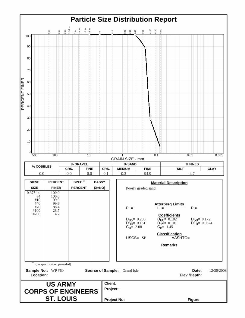
(X=NO)PERCENTFINERSIZEPASS?SPEC.*PERCENTSIEVE
Project No:
Project:Client:
Elev./Depth:Location:Date:Source of Sample:Sample No.:
Remarks
Classification
Coefficients
Atterberg Limits
Material Description
*
AASHTO=USCS=
Cc=Cu=D10=D15=D30=D50=D60=D85=
PI=LL=PL=
Particle Size Distribution Report
10
20
30
40
50
60
70
80
90
0
100
PE
RC
EN
T FI
NE
R
100 10 1 0.1 0.01 0.001500GRAIN SIZE - mm
% COBBLES% GRAVEL
CRS. FINE% SAND
CRS. MEDIUM FINE% FINES
SILT CLAY
6 in
.
3 in
.
2 in
.
1-1/
2 in
.
1 in
.
3/4
in.
1/2
in.
3/8
in.
#4 #10
#20
#30
#40
#60
#100
#140
#200
0.0 0.0 0.0 0.1 0.3 94.9 4.7
Figure
12/30/2008Grand IsleWP #60
SP
1.452.080.08740.1010.1510.1720.1820.206
Poorly graded sand
(no specification provided)
US ARMYCORPS OF ENGINEERS
ST. LOUIS
100.0100.0
99.999.688.428.7
4.7
0.375 in.#4
#10#40#70
#100#200

(X=NO)PERCENTFINERSIZEPASS?SPEC.*PERCENTSIEVE
Project No:
Project:Client:
Elev./Depth:Location:Date:Source of Sample:Sample No.:
Remarks
Classification
Coefficients
Atterberg Limits
Material Description
*
AASHTO=USCS=
Cc=Cu=D10=D15=D30=D50=D60=D85=
PI=LL=PL=
Particle Size Distribution Report
10
20
30
40
50
60
70
80
90
0
100
PE
RC
EN
T FI
NE
R
100 10 1 0.1 0.01 0.001500GRAIN SIZE - mm
% COBBLES% GRAVEL
CRS. FINE% SAND
CRS. MEDIUM FINE% FINES
SILT CLAY
6 in
.
3 in
.
2 in
.
1-1/
2 in
.
1 in
.
3/4
in.
1/2
in.
3/8
in.
#4 #10
#20
#30
#40
#60
#100
#140
#200
0.0 0.0 0.0 0.1 0.1 92.3 7.5
Figure
12/30/2008Grand IsleWP #61
SP-SM
1.572.210.08180.09730.1530.1720.1810.204
Poorly graded sand with silt
(no specification provided)
US ARMYCORPS OF ENGINEERS
ST. LOUIS
100.0100.0
99.999.891.127.5
7.5
0.375 in.#4
#10#40#70
#100#200

Geotechnical Report
Grand Isle and Vicinity Hurricane Protection Project Rehabilitation to Hurricane Katrina Damages - 2005 Jefferson Parish, LA Contract No. W912P8-06-D-0033
July 6, 2007
Prepared For: US Army Corps of Engineers New Orleans District Prepared By: HNTB Corporation

Geotechnical Report for Grand Isle & Vicinity Hurricane Protection Project Contract W912P8-06-D-0033 July 6, 2007
TABLE OF CONTENTS 1.0 INTRODUCTION................................................................................................1 2.0 GEOTECHNICAL SCOPE OF WORK ..............................................................1 3.0 SUBSURFACE EXPLORATION PROGRAM ..................................................1 4.0 GEOLOGY & SUBSURFACE CONDITIONS...................................................1 5.0 RECOMMENDATIONS ....................................................................................2 6.0 LIMITATIONS...................................................................................................2
LIST OF APPENDICES APPENDIX A BORING LOCATION MAP & BORINGS APPENDIX B LABORATORY RESULTS

Geotechnical Report for Grand Isle & Vicinity Hurricane Protection Project Page 1 Contract W912P8-06-D-0033 July 6, 2007
1.0 INTRODUCTION The work referenced in this report is located in Jefferson Parish, Louisiana, and is part of the Grand Isle and Vicinity Hurricane Protection Project. The site of work is 7.5 miles of beach and the area immediately off the southern beach on Grand Isle, Louisiana. The project consists of rehabilitating or replacing-in-kind 20 out of 23 breakwaters, 2 jetties, sand dunes, sand fencing and plantings, emergency vehicles cross-overs, and wooden pedestrian crosswalks.
2.0 GEOTECHNICAL SCOPE OF WORK The geotechnical project scope of work consists of obtaining geotechnical data to confirm the predetermined sand borrow area’s suitability and availability. The geotechnical report was to include the boring logs, laboratory data, and construction recommendations for the sand dunes.
3.0 SUBSURFACE EXPLORATION PROGRAM The subsurface exploration program consisted of drilling 18 borings (B-1 through B-18) to approximately 20 feet below the mud line. Borings were drilled between March 13 and 21, 2007 by Eustis Engineering from a barge just off the Grand Isle beach in two previously used sand borrow pit areas in 1991 and 1993. Boring locations are presented on the Boring Location Map in Appendix A. Coordinates of the borings were provided by HNTB to Eustis, who identified the locations in the field by a global positioning system (GPS). Soil sampling was performed using 2.5-inch outside diameter split-spoon sampling in sands and 3-inch Shelby tubes in clay. In general, samples were spaced at 2.5-foot centers for the first 10 feet and 5-foot centers for the second 10 feet. All drilling and sampling procedure were performed according to USACE requirements. Classification of soil samples and preparation of the boring and lab logs were completed by Eustis. These logs were included in the plans and are shown in Appendix A. Selection of corresponding testing assignments was identified by HNTB. Eustis performed the laboratory testing and provided HNTB the results. Laboratory tests conducted included Moisture Content tests and Particle Size Distribution tests. Testing procedures and protocols were according to USACE requirements identified in applicable Engineering Manuals (EMs). Summary of the laboratory reports, lab logs, and particle-size distribution curves are presented in Appendix B.
4.0 GEOLOGY & SUBSURFACE CONDITIONS In addition to reviewing the existing borings, the 1979 Phase I General Design Memorandum for the Grand Isle & Vicinity in Louisiana was reviewed. The DM indicated that the geology in the area is located on a deltaic plain of the Mississippi River, a region of low relief. As stated in the DM, during the last 4,000 to 5,000 years, the rise in the sea level ceased, many deltas were formed, and a gulfward growth of land mass began. This land mass started to shift seaward as the course of the Mississippi River and deltas changed and deposited fine-grained alluvium. Over many changes in the course of the Mississippi and corresponding deltas, subsidence and erosion became more prevalent, and the abandoned delta then began to move landward forming sand delta margin islands with well-developed beaches.
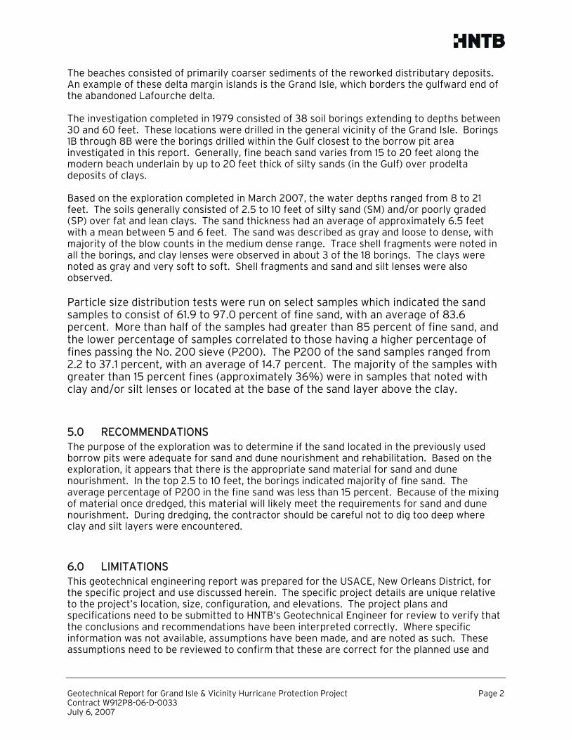
Geotechnical Report for Grand Isle & Vicinity Hurricane Protection Project Page 2 Contract W912P8-06-D-0033 July 6, 2007
The beaches consisted of primarily coarser sediments of the reworked distributary deposits. An example of these delta margin islands is the Grand Isle, which borders the gulfward end of the abandoned Lafourche delta. The investigation completed in 1979 consisted of 38 soil borings extending to depths between 30 and 60 feet. These locations were drilled in the general vicinity of the Grand Isle. Borings 1B through 8B were the borings drilled within the Gulf closest to the borrow pit area investigated in this report. Generally, fine beach sand varies from 15 to 20 feet along the modern beach underlain by up to 20 feet thick of silty sands (in the Gulf) over prodelta deposits of clays. Based on the exploration completed in March 2007, the water depths ranged from 8 to 21 feet. The soils generally consisted of 2.5 to 10 feet of silty sand (SM) and/or poorly graded (SP) over fat and lean clays. The sand thickness had an average of approximately 6.5 feet with a mean between 5 and 6 feet. The sand was described as gray and loose to dense, with majority of the blow counts in the medium dense range. Trace shell fragments were noted in all the borings, and clay lenses were observed in about 3 of the 18 borings. The clays were noted as gray and very soft to soft. Shell fragments and sand and silt lenses were also observed. Particle size distribution tests were run on select samples which indicated the sand samples to consist of 61.9 to 97.0 percent of fine sand, with an average of 83.6 percent. More than half of the samples had greater than 85 percent of fine sand, and the lower percentage of samples correlated to those having a higher percentage of fines passing the No. 200 sieve (P200). The P200 of the sand samples ranged from 2.2 to 37.1 percent, with an average of 14.7 percent. The majority of the samples with greater than 15 percent fines (approximately 36%) were in samples that noted with clay and/or silt lenses or located at the base of the sand layer above the clay.
5.0 RECOMMENDATIONS The purpose of the exploration was to determine if the sand located in the previously used borrow pits were adequate for sand and dune nourishment and rehabilitation. Based on the exploration, it appears that there is the appropriate sand material for sand and dune nourishment. In the top 2.5 to 10 feet, the borings indicated majority of fine sand. The average percentage of P200 in the fine sand was less than 15 percent. Because of the mixing of material once dredged, this material will likely meet the requirements for sand and dune nourishment. During dredging, the contractor should be careful not to dig too deep where clay and silt layers were encountered.
6.0 LIMITATIONS This geotechnical engineering report was prepared for the USACE, New Orleans District, for the specific project and use discussed herein. The specific project details are unique relative to the project’s location, size, configuration, and elevations. The project plans and specifications need to be submitted to HNTB’s Geotechnical Engineer for review to verify that the conclusions and recommendations have been interpreted correctly. Where specific information was not available, assumptions have been made, and are noted as such. These assumptions need to be reviewed to confirm that these are correct for the planned use and

Geotechnical Report for Grand Isle & Vicinity Hurricane Protection Project Page 3 Contract W912P8-06-D-0033 July 6, 2007
project. If these assumptions are not correct, HNTB’s Geotechnical Engineer should be informed and allowed to modify the report, its conclusions, and recommendations. The accuracy and completeness of any documents or information provided by others as to project specifics or prior property uses have been reasonably relied on by the geotechnical engineer in providing its evaluation. In addition, if details of the planned construction change from those outlined in this report, HNTB’s Geotechnical Engineer must be notified to determine if the changes affect the recommendations. Supplemental recommendations may then need to be made. The analysis, conclusions, and recommendations in this report are based on the subsurface conditions present in the test boring and the engineering characteristics of the soil as determined through field and laboratory testing at this point in time, as defined in the current work scope. Subsurface conditions can change over time due to both natural and manmade forces, including changes in condition or use of adjacent properties. The report does not reflect variations in subsurface conditions that may exist between or beyond these borings. Variations in soil conditions should be expected, the nature and extent of which may not become evident until construction is undertaken. The construction is recommended to be monitored by the geotechnical engineer to determine if the subsurface conditions are as indicated by the boring and perform as anticipated. If the conditions encountered during construction are different from those inferred by the test boring or the project details and information provided to HNTB changes, HNTB Geotechnical Engineers must be contacted to determine if modification to the recommendation presented in this report are required. The recommendations found in this report are related and are not mutually exclusive of each other. Therefore no single portion of the report should be removed or be considered as a stand alone recommendation. Boring logs must also remain with the report as they are not to be interpreted on their own. The geotechnical engineering recommendations presented herein are an evaluation of subsoil performance based on the geotechnical engineer’s experience and professional opinion. These services were performed with the degree of skill and care normally utilized by other members of the geotechnical engineering profession practicing in this location at this time. No warranty is either expressed or implied. This report is intended for geotechnical design and construction purposes only and does not document the presence or absence of any environmental impacts at the site. Environmental services were specifically beyond the authorized scope of service. Any use or reuse of this report for any purpose other than as specifically intended hereunder without written verification by the Geotechnical engineer shall be at user’s own risk. Prepared by HNTB Corporation Therese Koutnik, P.E. Geotechnical Engineer

Geotechnical Report for Grand Isle & Vicinity Hurricane Protection Project Contract W912P8-06-D-0033 July 6, 2007
APPENDIX A
BORING LOCATION MAP & BORING LOGS

00
SC
AL
E: 1
’’ =
40
0’
400’
400’
80
0’
N
MATCH LINE - STA. 289+00
MATCH LINE - STA. 358+00
1200’
16
00
’
25 of 28 BORROW AREA
BORROW_05.DGN
SOLICITATION NO.:
FILE NAME:
DWN BY: CKD BY:
DESIGNED BY:
DESCRIPTION
1
D
23
C
45
A B
MARK APPR.
DATE:
FILE NUMBER:
SIZE:
SUBMITTED BY:
PLOT SCALE: PLOT DATE:
DATE MARK DESCRIPTION APPR.DATE
CONTRACT NO.:
US
AR
MY
CO
RP
S
OF
EN
GIN
EE
RS
NE
W O
RL
EA
NS
DIS
TR
ICT
U. S. ARMY ENGINEER DISTRICT
CORPS OF ENGINEERS
MISSISSIPPI VALLEY DIVISION
H-8-46405
200:1ANSI E
BATON ROUGE, LOUISIANA
9100 BLUEBONNET CENTRE BLVD.
SUITE 301
SH
EE
T
ID
EN
TIF
IC
AT
IO
N
NU
MB
ER
GRAND ISLE AND VICINITY HURRICANE
PROTECTION PROJECT
REHABILITATION TO HURRICANE KATRINA
DAMAGES - 2005
JEFFERSON PARISH, LA
KHM MLM
ROBERT IVARSON ___
6/28/2007
M. MAHONEY 7/6/2007
13
14
15
16
17
18
LO
UIS
IA
NA
HW
Y 1
G
R
A
N
D
I
S
L
E
AD
MIR
AL
CR
AIK
DR
IVE
3151
19
20
21
22
23
24
25
26
27
28
29
30
31
32
33
34
35
36
AD
MIR
AL
CR
AIK
DR
IVE
East E
nd
Jetty
GR
AN
D IS
LE
OR
LE
AN
S A
VE
.
YACHT HARBOR AVE.
EXXON GAS PLANT RD.
HELIPORT RD.
HATTERAS DR.
AQ
UA
SPO
RT D
R.
GU
LF
OF
ME
XI
CO
GU
LF
OF
ME
XI C
O
CU
RV
E 4
R=
750.00’
D=
07^38’22"
=76^00’00"
L=
994.84’
T=
585.96
C=
923.49’
M=
158.99’
E=
201.76’
CO
NS
TR
UC
TIO
N L
IMIT
S
R/W
BA
SE
LIN
E &
Existing R
/W
R/W
BA
SE
LIN
E &
Exis
ting R
/W
CL D
UN
E
CL D
UN
E
20’ C
ON
ST
RU
CT
ION
EA
SE
ME
NT
RE
PL
EN
IS
H B
EA
CH
AN
D D
UN
ET
O C
RO
WN
E
LE
VA
TIO
N 11.5’
RE
PL
EN
IS
H B
EA
CH
AN
D D
UN
ET
O C
RO
WN
E
LE
VA
TIO
N 11.5’
NA
VIG
AT
ION
LIG
HT
NA
VIG
AT
ION
LIG
HT
NA
VIG
AT
ION
LIG
HT
NA
VIG
AT
ION
LIG
HT
P
r
o
p
o
s
e
d
Sand F
ill
Proposed
Sand F
ill
Proposed
Sand F
ill
RE
PL
EN
ISH
BE
AC
H A
ND
DU
NE
TO
CR
OW
N E
LE
VA
TIO
N 1
1.5
’
LOMA LINDAAVE.
386+
00
EN
D P
RO
JE
CT
State P
ark R
am
p
(DO
NO
T D
IST
UR
B)
CO
NS
TR
UC
TIO
N L
IMIT
S
B
A
T
H
H
O
U
S
E
NO
. 1
BA
TH
HO
US
E
NO
. 2
CO
NS
TR
UC
TIO
N L
IMIT
S
BR
EA
KW
AT
ER
DO
NO
T D
IS
TU
RB
B
R
E
A
K
W
A
T
E
R
D
O
N
O
T
D
I
S
T
U
R
B
B
R
E
A
K
W
A
T
E
R
S
CO
NST
RU
CT
ION
EA
SE
ME
NT
CO
NS
TR
UC
TIO
N L
IMIT
S
RE
PL
EN
ISH
BE
AC
H A
ND
DU
NE
TO
CR
OW
N E
LE
VA
TIO
N 1
1.5
’
SA
ND
FE
NC
E
F
O
R
D
E
T
A
I
L
SE
E S
HE
ET
12 O
F 2
8
SA
ND
FE
NC
E
FO
R D
ET
AIL
SE
E S
HE
ET
12 O
F 2
8
PI 272+37.18
PI 282+27.35
PI 297+17.64
PI 312+60.49
PI 334+00.46
PI 349+25.39
PI 368+11.32
PI 372+30.13
PC
382+
80.00
236^02’33"
239^09’1
5"
241^29’58"
240^23’27"
214^09’56"
218^47’28"
220^47’56"
199^26’3
9"
123^28’47"
239^09’15"
218^47’28"
PT
392+
74.8
4=
ST
AM
PE
D 3
92+
03.4
7
dd
d
d
d
d
d
d
d
d
PR
EV
IOU
SL
Y U
SE
D
SA
ND
BO
RR
OW
AR
EA
(1991)
x=3729979.7
9318
y=273553.0
2378
x=3727847.7
9032
y=276330.0
5769
x=3727054.7
9410
y=275721.0
7104
x=3724923.8
1457
y=278498.0
9432
x=3722940.8
2417
y=276975.1
2801
x=3725070.8
1770
y=274198.0
9690
x=3727201.8
2819
y=271422.0
5838
PR
OP
OS
ED
BO
RIN
GS
BO
RR
OW
AR
EA
#1
B
O
R
R
O
W
A
R
E
A
#
2
PR
EV
IOU
SL
Y U
SE
D
SA
ND
BO
RR
OW
AR
EA
(1993)
50
0’
(TY
P.)
X=3725712.4
5142
Y=274685.5
4937
X=3727509.4
5502
Y=272345.5
4469
X=3729059.4
5812
Y=273535.5
4707
X=3729383.4
5877
Y=273090.5
4618
B-1
8B
-17
B-1
6
B-15
B-14
B-1
3
B-1
2B
-11
B-10
FR
EEPO
RT
SU
LFU
R L
INE
12" O
IL (E
XX
ON
PIP
ELIN
E C
O.)
16" OIL
(APA
CH
E C
OR
P.) A
BA
ND
ON
ED
12" OIL (EXXON PIPLINE CO.)
12" BB (EXXON PIPLINE CO.)
FREEPORTSULFUR LINE10" CRUDE OIL (APACHE CORP.)
8" H
UM
BL
E O
IL
PIP
EL
IN
E
12" H
UM
BL
E O
IL P
IPE
LIN
E
4" P
RO
PA
NE
LIN
E
GE
TT
Y O
IL
12" O
IL
P
IP
EL
IN
E
6" C
ON
OC
O G
AS
PIP
EL
INE
LA
PO
WE
R &
LIG
HT
CO
.
15 K
V S
UB
MA
RIN
E C
AB
LE
12" E
XX
ON
OIL
PIP
EL
INE
x=3724978.0
930
y=273840.9
162
x=3726952.4
430
y=271230.1
886
16" O
IL
(EX
XO
N P
IPELIN
E C
O) A
BA
ND
ON
ED
12" GA
S
(EX
XO
N PR
OD
UC
TIO
N U
SA)
NE
W L
INE
CO
OR
D PE
ND
ING
12" GA
S
(EX
XO
N PR
OD
UC
TIO
N U
SA)
12" O
IL
(AP
AC
HE
CO
RP
.) AB
AN
DO
NE
D
12" O
IL
(EX
XO
N P
IPELIN
E C
O.)
GULF COASTTELEPHONE CABLE (ABANDONED)
6" GAS(EXXON PRODUCTION USA)10" GAS
(EXXON PRODUCTION USA)
B-1
B-2
B-3
B-4
B-5
B-6
B-7
B-8
B-9

26 0f 28 SOIL_BORING_LOGS.DGN
29
slf
dG
r&
Gr
(1
1)
34
slf,C
S(3)
31
slf
(1
3)
30
slf,C
S(1
3)
SS
31
vS
o,slf
71
So
,slf
SS
69
So
Gr
BO
R. B
-1
ST
A. L
AT
N2
9^1
5’1
4.4
6" L
ON
G W
89
^5
6’4
1.0
4"
WA
TE
R D
EP
TH
= 1
0.0
’
13
MA
RC
H 2
00
7
W o
r D
10
CH
- F
at C
lay
CL
- L
ean C
lay
SM
- S
ilty S
and
SP
- S
an
d, P
oo
rly
G
rad
ed
0
0
-1
0
-2
0
-3
0
0
-1
0
-2
0
-3
0
DEPTH IN FEET
DEPTH IN FEET
Water
24
0.1100
Tr,slf
(2
7)
27
Tr,slf
(4
2)
31
0.0890
Tr,slf
(6)
31
Tr,slf
(1
6)
42
vS
o,slf
(3)
54
SS
56
So
Gr
BO
R. B
-2
ST
A. L
AT
N2
9^1
5’1
9.2
0" L
ON
G W
89
^5
6’3
4.4
4"
WA
TE
R D
EP
TH
= 1
5.0
’
19
MA
RC
H 2
00
7
W o
r D
10
CH
- F
at C
lay
CL
- L
ean C
lay
SM
- S
ilty S
and
SP
- S
an
d, P
oo
rly
G
rad
ed
0
0
-1
0
-2
0
-3
0
-4
0
0
-1
0
-2
0
-3
0
-4
0
DEPTH IN FEET
DEPTH IN FEET
WA
TE
R
28
0.1070
(3
3)
30
0.0
85
8(1
6)
27
0.0
85
0
Tr,slf
Br&
Gr
(3
6)
34
CS
,T
r,slf
(1
2)
33
So
,slf
64
SlS
47
So
Gr
BO
R. B
-3
ST
A. L
AT
N2
9^1
5’2
2.7
4" L
ON
G W
89
^5
6’2
7.2
4"
WA
TE
R D
EP
TH
= 8
.0’
19
MA
RC
H 2
00
7
W o
r D
10
CH
- F
at C
lay
CL
- L
ean C
lay
SM
- S
ilty S
and
SP
- S
an
d, P
oo
rly
G
rad
ed
0
0
-1
0
-2
0
-3
0
0
-1
0
-2
0
-3
0
DEPTH IN FEETDEPTH IN FEET
WA
TE
R
28
Tr,slf
Gr
(1
2)
30
Tr,slf
Gr&
Br
(1
6)
36
Tr,slf
Gr
(1
2)
28
CS
,T
r,slf
Br&
Gr
(1
1)
42
M,slf
(6)
SS
79
vS
o
SlS
49
So
Gr
BO
R. B
-4
ST
A. L
AT
N2
9^1
5’0
7.8
6" L
ON
G W
89
^5
6’3
6.2
4"
WA
TE
R D
EP
TH
= 1
0.0
’
19
MA
RC
H 2
00
7
W o
r D
10
CH
- F
at C
lay
CL
- L
ean C
lay
SM
- S
ilty S
and
0
0
-1
0
-2
0
-3
0
0
-1
0
-2
0
-3
0
DEPTH IN FEET
DEPTH IN FEET
WA
TE
R
29
Tr,slf
(2
8)
34
Tr,slf
(6)
31
Tr,W
d
39
50
45
So
SlS
55
So
Gr
BO
R. B
-5
ST
A. L
AT
N2
9^1
5’1
2.9
6" L
ON
G W
89
^5
6’2
9.5
2"
WA
TE
R D
EP
TH
= 1
4.0
’
19 M
AR
CH
2007
W o
r D
10
CH
- F
at C
lay
CL
- L
ean C
lay
SC
- C
layey S
and
SM
- S
ilty
S
an
d
0
0
-1
0
-2
0
-3
0
-4
0
0
-1
0
-2
0
-3
0
-4
0
DEPTH IN FEET
DEPTH IN FEET
WA
TE
R
25
0.1110
Tr,slf
(2
7)
29
Tr,slf
T&
Br
(2
2)
29
0.0
761
slf
(2
1)
56
vS
o,slf
(3
)
39
So
,slf
SS
62
So
49
vS
o
Gr
BO
R. B
-6
ST
A. L
AT
N2
9^1
5’1
6.5
6" L
ON
G W
89
^5
6’2
2.1
4"
WA
TE
R D
EP
TH
= 8
.0’
19 M
AR
CH
2007
W o
r D
10
CH
- F
at C
lay
CL
- L
ean C
lay
SM
- S
ilty
S
an
d
SP
- S
and, P
oorly G
raded
0
0
-1
0
-2
0
-3
0
0
-1
0
-2
0
-3
0
DEPTH IN FEET
DEPTH IN FEET
WA
TE
R
25
(1
4)
27
Tr,slf
(1
9)
27
CS
(7)
51
vS
o,S
(3)
29
slf
29
So
,slf
37
So
Gr
BO
R. B
-7
ST
A. L
AT
N2
9^1
5’0
0.8
4" L
ON
G W
89
^5
6’2
8.9
8"
WA
TE
R D
EP
TH
= 1
5.0
’
19 M
AR
CH
2007
W o
r D
10
CH
- F
at C
lay
CL
- L
ean C
lay
SM
- S
ilty
S
an
d
0
0
-1
0
-2
0
-3
0
-4
0
0
-1
0
-2
0
-3
0
-4
0
DEPTH IN FEET
DEPTH IN FEET
WA
TE
R
28
(1
5)
31
Tr,slf
(1
4)
36
vS
o,T
r,slf
(1)
SS
49
So
SlS
43
So
,S
33
So
,slf
Gr
BO
R. B
-8
ST
A. L
AT
N2
9^1
5’0
5.2
2" L
ON
G W
89
^5
6’2
2.3
8"
WA
TE
R D
EP
TH
= 1
4.0
’
21
MA
RC
H 2
00
7
W o
r D
10
CH
- F
at C
lay
CL
- L
ean
C
lay
SM
- S
ilty
S
an
d
0
0
-1
0
-2
0
-3
0
-4
0
0
-1
0
-2
0
-3
0
-4
0
DEPTH IN FEET
DEPTH IN FEET
WA
TE
R
26
(1
8)
29
Tr,slf
(9)
52
SlS
,vS
o,T
r,slf
(3)
SS
54
SlS
61
So
44
So
,slf
Gr
BO
R. B
-9
ST
A. L
AT
N2
9^1
5’0
8.2
2" L
ON
G W
89
^5
6’1
5.4
8"
WA
TE
R D
EP
TH
= 1
4.0
’
21 M
AR
CH
2007
W o
r D
10
CH
- F
at C
lay
CL
- L
ean C
lay
SM
- S
ilty
S
an
d
0
0
-1
0
-2
0
-3
0
-4
0
0
-1
0
-2
0
-3
0
-4
0
DEPTH IN FEET
DEPTH IN FEET
WA
TE
R
25
0.0760
Tr,slf
(2
6)
27
(1
5)
28
Tr,slf
(1
2)
37
33
35
So
,slf
Gr
BO
R. B
-11
ST
A. L
AT
N2
9^1
4’5
8.6
8" L
ON
G W
89
^5
6’1
7.3
4"
WA
TE
R D
EP
TH
= 1
3.0
’
21 M
AR
CH
2007
W o
r D
10
CL
- L
ean C
lay
SM
- S
ilty
S
an
d
SP
- S
and, P
oorly G
raded
0
0
-1
0
-2
0
-3
0
-4
0
0
-1
0
-2
0
-3
0
-4
0
DEPTH IN FEET
DEPTH IN FEET
WA
TE
R
28
Tr,slf
(6
)
24
0.0790
Tr,slf
(1
2)
46
SlS
,vS
o,T
r,slf
(2
)
46
So
39
So
,slf
37
So
Gr
BO
R. B
-10
ST
A. L
AT
N2
9^1
4’5
4.3
6" L
ON
G W
89
^5
6’2
4.1
8"
WA
TE
R D
EP
TH
= 1
0.0
’
21 M
AR
CH
2007
W o
r D
10
CH
- F
at C
lay
CL
- L
ean C
lay
SM
- S
ilty
S
an
d
SP
- S
and, P
oorly G
raded
0
0
-1
0
-2
0
-3
0
0
-1
0
-2
0
-3
0
DEPTH IN FEET
DEPTH IN FEET
WA
TE
R
27
Tr,slf
(1
3)
32
0.0
80
0T
r,slf
(1
0)
44
vS
o,T
r,slf
(0)
52
vS
o,slf
39
40
So
,slf
Gr
BO
R. B
-1
2
ST
A. L
AT
N2
9^1
5’0
3.6
0" L
ON
G W
89
^5
6’1
1.1
0"
WA
TE
R D
EP
TH
= 1
5.0
’
21
MA
RC
H 2
00
7
W o
r D
10
CL
- L
ean C
lay
SM
- S
ilty S
and
SP
- S
an
d, P
oo
rly
G
rad
ed
0
0
-1
0
-2
0
-3
0
-4
0
0
-1
0
-2
0
-3
0
-4
0
DEPTH IN FEET
DEPTH IN FEET
WA
TE
R
SOIL BORING LOGS
SOLICITATION NO.:
FILE NAME:
DWN BY: CKD BY:
DESIGNED BY:
DESCRIPTION
1
D
23
C
45
A B
MARK APPR.
DATE:
FILE NUMBER:
SIZE:
SUBMITTED BY:
PLOT SCALE: PLOT DATE:
DATE MARK DESCRIPTION APPR.DATE
CONTRACT NO.:
US
AR
MY
CO
RP
S
OF
EN
GIN
EE
RS
NE
W O
RL
EA
NS
DIS
TR
ICT
U. S. ARMY ENGINEER DISTRICT
CORPS OF ENGINEERS
MISSISSIPPI VALLEY DIVISION
H-8-46405
200:1ANSI E
BATON ROUGE, LOUISIANA
9100 BLUEBONNET CENTRE BLVD.
SUITE 301
SH
EE
T
ID
EN
TIF
IC
AT
IO
N
NU
MB
ER
LDE STH
GRAND ISLE AND VICINITY HURRICANE
PROTECTION PROJECT
REHABILITATION TO HURRICANE KATRINA
DAMAGES - 2005
JEFFERSON PRRISH, LA
ROBERT IVARSON ___
6/28/2007
S. HAGUE 7/6/2007

27 0f 28 SOIL_BORING_LOGS.DGN
26
slf
(1
5)
25
Tr,slf,C
S(7
)
31
Tr,slf,C
S(3
)
68
SS
52
So
31
So
Gr
BO
R. B
-1
4
ST
A. L
AT
N2
9^1
4’3
9.6
0" L
ON
G W
89
^5
6’1
3.6
2"
WA
TE
R D
EP
TH
= 1
4.0
’
19
MA
RC
H 2
00
7
W o
r D
10
CH
- F
at C
lay
CL
- L
ean C
lay
ML
- S
ilt, L
ow
P
lasticity
SM
- S
ilty
S
an
d
0
0
-1
0
-2
0
-3
0
-4
0
0
-1
0
-2
0
-3
0
-4
0
DEPTH IN FEET
DEPTH IN FEET
WA
TE
R
26
0.0
93
9slf
(1
7)
28
Tr,slf
(1
1)
44
vS
o,T
r,slf,T
r,O
(2)
39
So
,S
SlS
48
So
22
Tr,slf
Gr
BO
R. B
-1
5
ST
A. L
AT
N2
9^1
4’3
2.1
0" L
ON
G W
89
^5
6’0
6.5
4"
WA
TE
R D
EP
TH
= 1
2.0
’
20
MA
RC
H 2
00
7
W o
r D
10
CH
- F
at C
lay
CL
- L
ean C
lay
SM
- S
ilty
S
an
d
SP
- S
an
d, P
oo
rly
G
rad
ed
0
0
-1
0
-2
0
-3
0
-4
0
0
-1
0
-2
0
-3
0
-4
0
DEPTH IN FEET
DEPTH IN FEET
WA
TE
R
26
0.0
764
Tr,slf
(1
4)
28
Tr,slf
(1
1)
44
vS
o,T
r,slf
(2)
46
So
51
SlS
55
So
Gr
BO
R. B
-1
6
ST
A. L
AT
N2
9^1
4’2
4.3
6" L
ON
G W
89
^5
6’0
0.0
6"
WA
TE
R D
EP
TH
= 1
3.0
’
20
MA
RC
H 2
00
7
W o
r D
10
CH
- F
at C
lay
CL
- L
ean
C
lay
SM
- S
ilty
S
an
d
SP
- S
and, P
oorly G
raded
0
0
-1
0
-2
0
-3
0
-4
0
0
-1
0
-2
0
-3
0
-4
0
DEPTH IN FEET
DEPTH IN FEET
WA
TE
R
25
(1
6)
30
Tr,slf
(7)
61
vS
o,slf
(1)
61
vS
o
45
So
SlS
57
So
Gr
BO
R. B
-1
7
ST
A. L
AT
N2
9^1
4’3
0.2
4" L
ON
G W
89
^5
5’5
1.5
4"
WA
TE
R D
EP
TH
= 1
4.0
’
20
MA
RC
H 2
00
7
W o
r D
10
CH
- F
at C
lay
CL
- L
ean C
lay
SM
- S
ilty
S
an
d
0
0
-1
0
-2
0
-3
0
-4
0
0
-1
0
-2
0
-3
0
-4
0
DEPTH IN FEET
DEPTH IN FEET
WA
TE
R
26
Tr,slf
(1
3)
54
vS
o,S
(1)
47
So
44
So
,S
SlS
56
So
63
So
,S
Gr
BO
R. B
-1
8
ST
A. L
AT
N2
9^1
4’3
7.2
0" L
ON
G W
89
^5
5’4
2.9
6"
WA
TE
R D
EP
TH
= 2
1.0
’
20
MA
RC
H 2
00
7
W o
r D
10
CH
- F
at C
lay
CL
- L
ean C
lay
SM
- S
ilty
S
an
d
0
-1
0
-2
0
-3
0
-4
0
-5
0
0
-1
0
-2
0
-3
0
-4
0
-5
0
DEPTH IN FEET
DEPTH IN FEET
WA
TE
R
0
26
0.0
879
Tr,slf
(2
0)
27
Tr,slf
(1
3)
47
vS
o,slf
(3)
54
So,slf,S
SS
66
So
22
slf
29
So
,slf
Gr
BO
R. B
-1
3
ST
A. L
AT
N2
9^1
4’4
7.5
6" L
ON
G W
89
^5
6’2
0.1
6"
WA
TE
R D
EP
TH
= 1
5.0
’
19
MA
RC
H 2
00
7
W o
r D
10
CH
- F
at C
lay
CL
- L
ean C
lay
SM
- S
ilty S
and
SP
- S
an
d, P
oo
rly
G
rad
ed
0
0
-1
0
-2
0
-3
0
-4
0
0
-1
0
-2
0
-3
0
-4
0
DEPTH IN FEET
DEPTH IN FEET
WA
TE
R
SOIL BORING LOGS
SOLICITATION NO.:
FILE NAME:
DWN BY: CKD BY:
DESIGNED BY:
DESCRIPTION
1
D
23
C
45
A B
MARK APPR.
DATE:
FILE NUMBER:
SIZE:
SUBMITTED BY:
PLOT SCALE: PLOT DATE:
DATE MARK DESCRIPTION APPR.DATE
CONTRACT NO.:
US
AR
MY
CO
RP
S
OF
EN
GIN
EE
RS
NE
W O
RL
EA
NS
DIS
TR
ICT
U. S. ARMY ENGINEER DISTRICT
CORPS OF ENGINEERS
MISSISSIPPI VALLEY DIVISION
H-8-46405
200:1ANSI E
BATON ROUGE, LOUISIANA
9100 BLUEBONNET CENTRE BLVD.
SUITE 301
SH
EE
T
ID
EN
TIF
IC
AT
IO
N
NU
MB
ER
LDE STH
GRAND ISLE AND VICINITY HURRICANE
PROTECTION PROJECT
REHABILITATION TO HURRICANE KATRINA
DAMAGES - 2005
JEFFERSON PRRISH, LA
ROBERT IVARSON ___
6/28/2007
S. HAGUE 7/6/2007

Geotechnical Report for Grand Isle & Vicinity Hurricane Protection Project Contract W912P8-06-D-0033 July 6, 2007
APPENDIX B
LABORATORY RESULTS


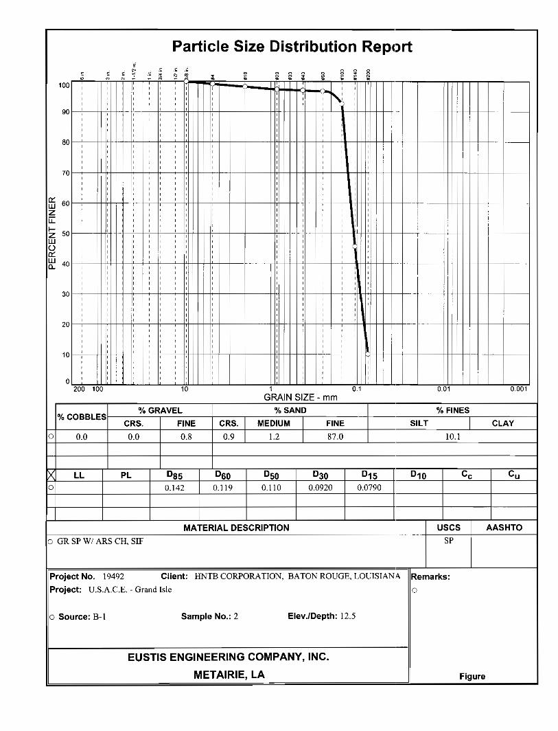


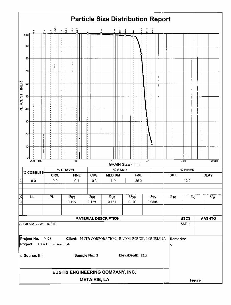
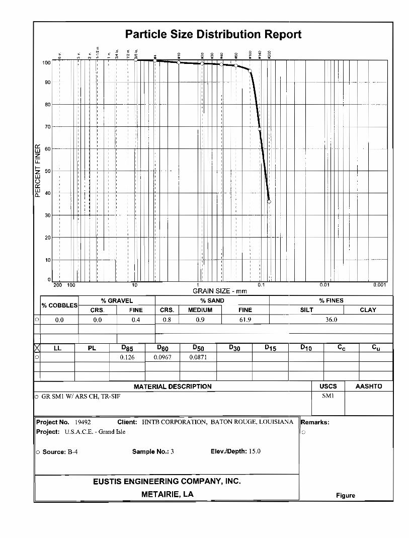

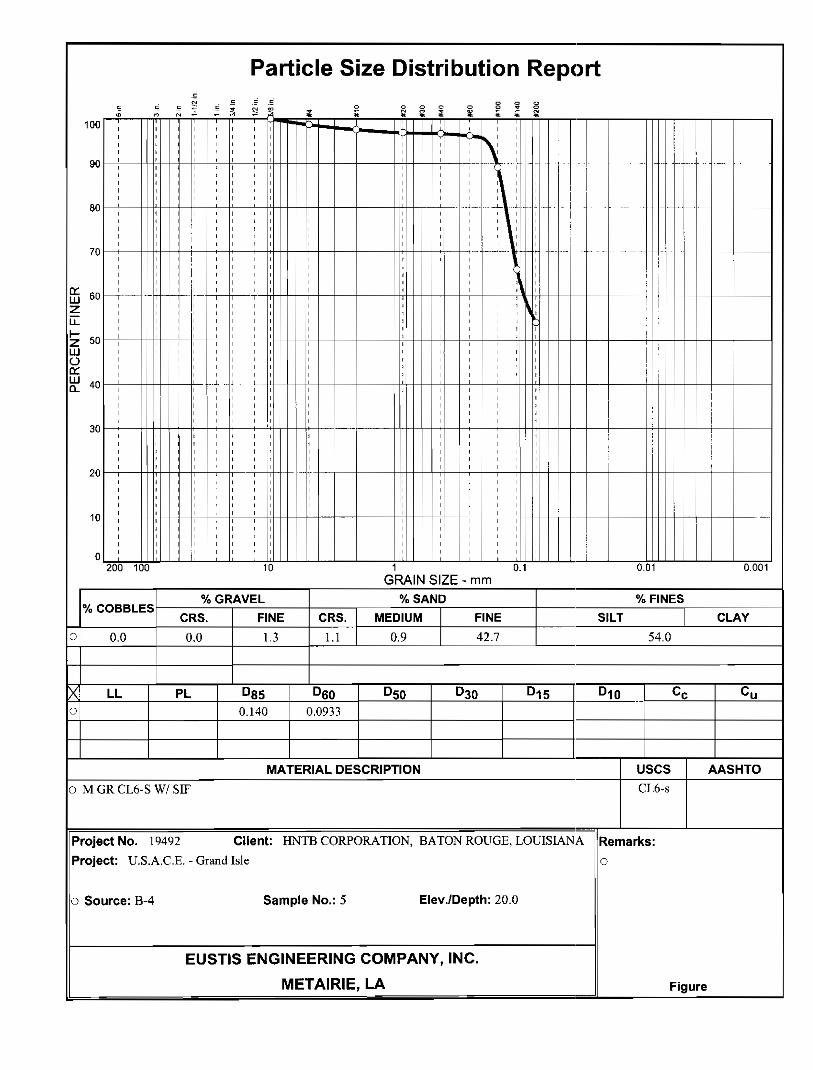

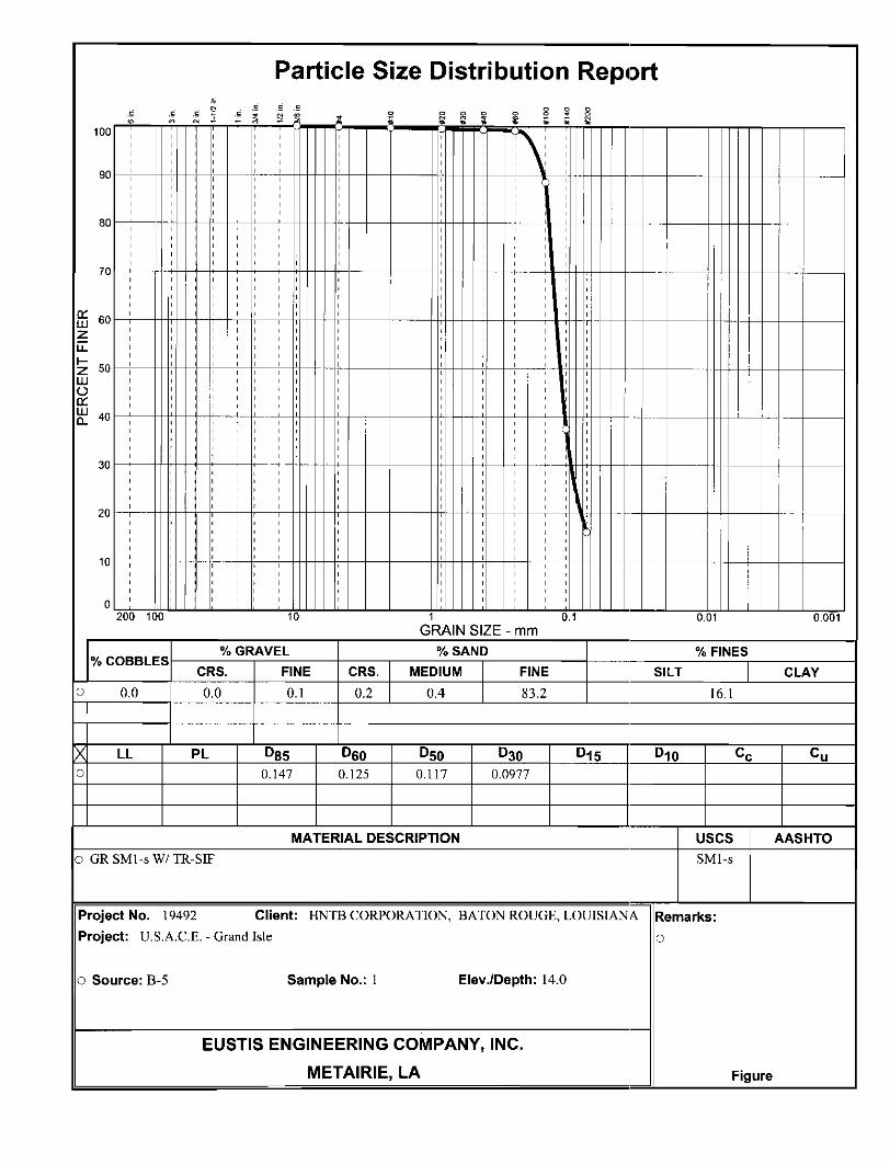


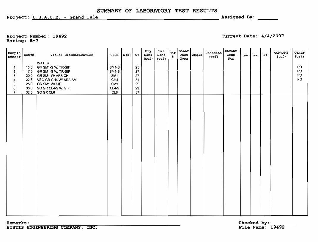


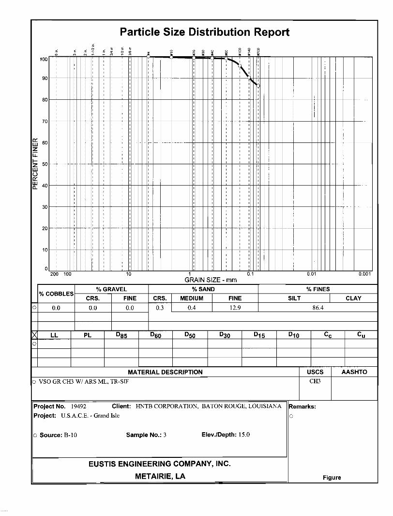

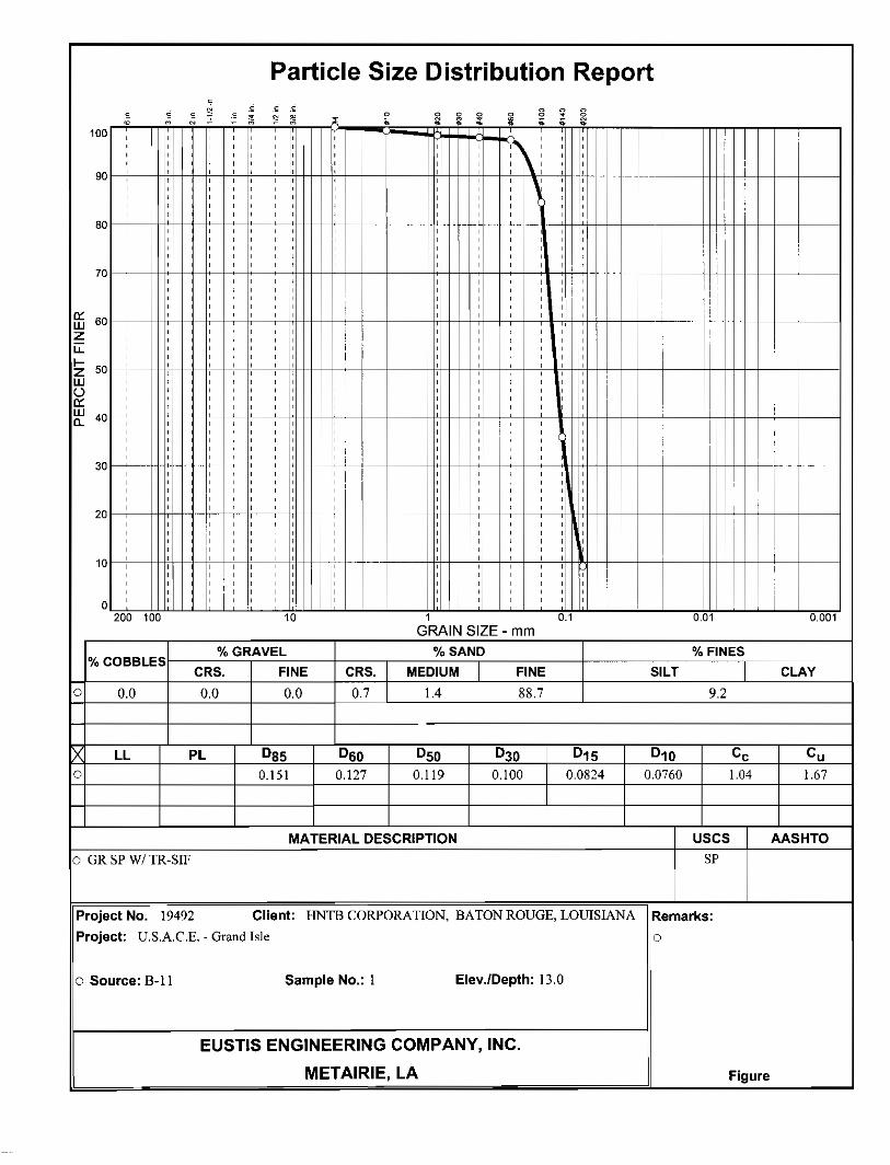


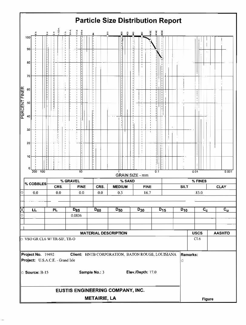


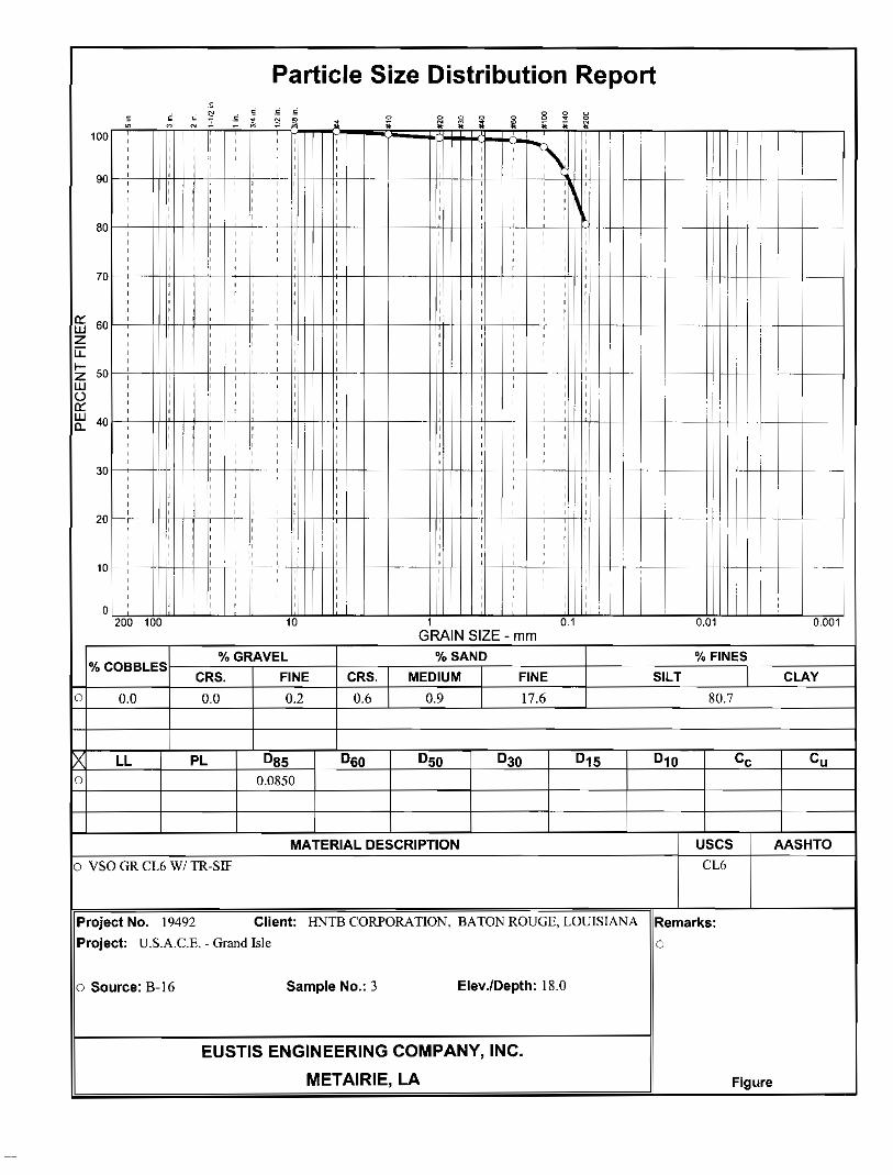


Section Table of Contents
SECTION 02333- BEACH AND DUNE SAND COVER PART 1 GENERAL 1
1.1 SCOPE 1 1.2 REFERENCES 1 1.3 QUALITY CONTROL 1
1.3.1 General 1 1.3.2 Reporting 2
1.4 BEACH NOURISHMENT AND DUNE SAND COVER MATERIALS 2 1.4.1 Dune Sand Cover and Beach Nourishment Sand 2
PART 2 PRODUCTS (Not Applicable) 3 PART 3 EXECUTION 3
3.1 BEACH AND DUNE SAND COVER PLACEMENT 3 3.2 GRADE TOLERANCES 3
3.2.1 Beach 3 3.2.2 Dune Sand Cover 4
3.3 DITCHES AND DEPRESSIONS 4 3.3.1 Surveys 4
3.3.1.1 Final Grade 4 3.4 CROSS SECTIONS 4
3.4.1 Beach and Dune Sections 4 3.5 ACCESS ROADS 4
3.5.1 Access Roads 4 3.5.2 Maintenance 5
02333-a ED 09-075

SECTION 02333 – BEACH AND DUNE SAND COVER PART 1 GENERAL 1.1 SCOPE
The work covered by this section consists of furnishing all plant, labor, equipment, and materials and performing all operations in connection with placing and grading sand fill for beach nourishment and dune sand cover construction (after placement of geotextile tubes), Contractor constructed access roads, and other incidental earthwork as may be necessary to complete the beach and dune sand cover, as shown on the drawings, and as hereinafter specified.
1.2 REFERENCES
The following publications of the issues listed below, but referred to before and thereafter by the basic designation only, form a part of this specification to the extent indicated by the references thereto:
AMERICAN SOCIETY FOR TESTING AND MATERIALS (ASTM) STANDARD D698-91 Moisture-Density Relations of Soils and Soil-Aggregate Mixtures
Using a 5.5 lb. Rammer and a 12-inch Drop D1556-90 Density of Soil in Place by the Sand-Cone Method D2216-80 Laboratory Determination of Water, (Moisture) Content of Soil-
Aggregate Mixtures D2487-93 Classification of Soils for Engineering Purposes D2922-91 Density of Soil and Soil-Aggregate in Place by Nuclear Methods
(Shallow Depth) D3740-80 Evaluation of Agencies Engaged in the Testing and/or Inspection
of Soil and Rock as used in Engineering Design and Construction D4318-93 Liquid Limit, Plastic Limit, and Plasticity Index of Soils
1.3 QUALITY CONTROL 1.3.1 General
The Contractor shall establish and maintain quality control for beach nourishment and dune sand cover construction operations to assure
02333-1 ED 09-075

compliance with contract requirements, and maintain records of its quality control for all construction operations including but not limited to the following: (1) Equipment. Type, size, and suitability for construction of the prescribed work. (2) Materials. Suitability. (3) Construction. Layout, site grading for drainage, and spreading sand for beach and dune cover. (4) Grade and Cross Section. Crown width, crown slope, side slopes, and grades. (5) Roads and Ramps. Location of Contractor constructed access roads. Location and placement of fills for ramps in accordance with specified dimensions and grades. (6) Grade Tolerances. Check fills to determine if placement conforms to prescribed grade and cross section.
1.3.2 Reporting
The original and two copies of these records of inspections and tests, as well as the records of corrective action taken, shall be furnished the Government daily. Format of the report shall be as prescribed in Section 01451, "CONTRACTOR QUALITY CONTROL".
1.4 BEACH NOURISHMENT AND DUNE SAND COVER MATERIALS 1.4.1 Dune Sand Cover and Beach Nourishment Sand
(1) Dune Sand Cover construction material shall be obtained from the dredge borrow area (as shown on the drawings) or from material left over from the excavation of the existing dune after the filling of all geotextile tubes. (2) Materials which are unsuitable for dune cover construction are defined as masses of organic matter, sticks, branches, roots, and other debris. Earthen materials from the designated borrow area may contain excessive amounts of clay, sea shell, and wood. Isolated pieces of these materials will not be considered objectionable in the dune provided their length does not exceed one foot, their volume does not exceed 48 cubic inches, and they are distributed throughout the fill.
02333-2 ED 09-075

PART 2 PRODUCTS (Not Applicable) PART 3 EXECUTION 3.1 BEACH AND DUNE SAND COVER PLACEMENT
(1) General. The dune cover consists of sand placed over the geotextile tube from Sta. 85+00 to 386+00 and sand placed over the existing clay filled geotextile wrap from Sta. 8+80 to 85+00. The sand material will also be used to nourish the beach to design grades including along the landside of the West End Jetty from Sta 0+00 to 8+80. (2) The dune sand cover shall be placed in accordance with the applicable provisions of the plans and specifications. A plan of operations shall be prepared and submitted at the preconstruction meeting by the Contractor, in writing and reviewed by the Contracting Officer. (3) The Contractor shall remove all masses of organic matter and other debris from the dune promptly and before such objectionable material is covered. Such debris shall be disposed of as specified in Section 01352 ENVIRONMENTAL PROTECTION. (4) The areas of work shall be brought to not less than the prescribed design cross section at all points, except as provided in paragraph 3.2. All surfaces shall be dressed and constructed to drain. (5) No damage to the geotextile tube core of the dune structure or its scour apron and scour tubes shall be permitted. The Contractor should operate equipment in such a manner as necessary to not harm these works. Any damage to the geotextile tube core of the dune structure shall be reported immediately to the Contracting Officer. The Contractor shall repair or replace as to the satisfaction of the Contracting Officer at no additional expense to the government.
3.2 GRADE TOLERANCES 3.2.1 Beach
The beach shall be constructed to the grade and cross section shown on the drawings subject to the following tolerances. For sand fill above El. 1.5 NAVD88, a tolerance of +/-6 inches is permitted. For sand fill below El. 1.5 NAVD88, a tolerance of +/-1 foot is permitted.
02333-3 ED 09-075
3.2.2 Dune Sand Cover
On the full length of the dune, excess material shall be so distributed that the crown of the dune drains, there are no abrupt humps or depressions in surfaces or bulges in the width of the crown, and the side slopes are uniform. The crown height shall have a tolerance of +6 inches.
3.3 DITCHES AND DEPRESSIONS
All ditches and depressions beyond the limits of the dune, but within the rights-of-way or temporary construction easement, shall be filled with suitable material, as described in paragraph 1.4.1 to a height sufficient to insure drainage at the direction of the Contracting Officer. This work will be completed at no additional cost to the government.
3.3.1 Surveys 3.3.1.1 Final Grade
After placement of the Dune Sand Cover and Beach Fill, the Contractor shall take final cross section surveys over the work area every 100 feet perpendicular to the beach to ensure that all design requirements in this specification and on the drawings have been met. Promptly upon completion of a survey, the Contractor shall furnish the originals of all field notes and all other records relating to the survey to the Contracting Officer. The Contractor shall retain copies of all such material furnished to the Contracting Officer.
3.4 CROSS SECTIONS 3.4.1 Beach and Dune Sections
Unless otherwise specified, the dimensions and slopes shall conform to the applicable cross sections including the allowable tolerance, shown on the drawings.
3.5 ACCESS ROADS 3.5.1 Access Roads
Access roads are indicated on drawings. They shall be maintained in good conditions throughout the contract period and restored to pre-construction conditions upon completion of construction. The pre-construction and post-construction conditions shall be verified/documented by the use of Contractor furnished surveys, photographs and/or videos at the direction of the Contracting Officer. In addition to all Contract Clauses, the Contractor shall take note of the Contract Clauses entitled "PERMITS AND
02333-4 ED 09-075

02333-5 ED 09-075
RESPONSIBILITIES""(FAR 52.236-7) and "OPERATIONS AND STORAGE AREAS"(FAR 52.236-10) in the performance of the work required herein. The Contractor should also be aware that truck routes and truck speed limits are subject to change and he should check with the appropriate state and/or parish officials for the applicable regulations in performance of this construction work. In addition to the requirements stated above, the Contractor shall keep any public street used free and clean of mud and other debris resulting from his operations. This is necessary to insure safe operation of all vehicles using public streets.
3.5.2 Maintenance
Shell/crushed stone access roads in the East End State Park shall be maintained by such blading, shaping, and addition of surfacing material as directed by the Contracting Officer to provide a usable and drivable road under all weather conditions during the construction period. Upon completion of construction, the Contractor will return the road to preconstruction conditions. No separate additional payment will be made for blading and shaping operations, or additional surfacing materials, and all costs shall be distributed throughout the existing bid items.

Section Table of Contents
SECTION 02382- EMERGENCY VEHICLE CROSSOVERS PART 1 GENERAL 1
1.1 SCOPE 1 1.2 REFERENCES 1 1.3 SURVEYS 1 1.4 SUBMITTALS 1
1.4.1 Block Installation; Geotextile (Carrier Fabric) Installation 1 1.4.2 Articulated Concrete Block; Geotextile (Carrier Fabric) 2 1.4.3 Articulated Concrete Block 2
1.5 SCHEDULE 2 1.6 DELIVERY, STORAGE AND HANDLING 2
PART 2 PRODUCTS 2 2.1 CELLULAR CONCRETE BLOCK MATS 2 2.2 CARRIER FABRIC 3
PART 3 EXECUTION 3 3.1 CONSTRUCTION EQUIPMENT CROSSOVERS 3 3.2 SUBGRADE PREPARATION 3
3.2.1 Removal of Remaining Portions of Existing Ramps 3 3.2.2 Ramps Locations 3
3.3 BLOCK INSTALLATION 4 3.3.1 Placement of Pre-Assembled Mattresses 4 3.3.2 Tolerances 4
02382-a ED 09-075

SECTION 02382 – EMERGENCY VEHICLE CROSSOVERS PART 1 GENERAL 1.1 SCOPE
The work covered by this section consists of furnishing all labor and materials and performing all work necessary to construct and maintain the concrete block pavement for the emergency vehicle crossover ramps as indicated on the drawings.
1.2 REFERENCES
The publications listed below form a part of this specification to the extent referenced. The publications are referred to within the text by the basic designation only.
AMERICAN SOCIETY FOR TESTING AND MATERIALS (ASTM) STANDARD D4873-02 Identification, Storage, and Handling of Geosynthetic Rolls and Samples
1.3 SURVEYS
The contractor shall conduct a centerline survey over the entire length of each emergency vehicle crossover. Survey points shall be spaced every 10 feet. All original field notes, computations and other records for the purpose of layout of surveys conducted by the Contractor shall be recorded in duplicating field books, the original pages of which shall be furnished promptly to the Contracting Officer, or his representative, at the site of work. The Contractor shall furnish the Contracting Officer, or his representative, profile data for the survey on a computer disk. The survey data shall be in an X, Y, Z format, and stored on CD's compatible with the MS-DOS operating system. The Contractor shall submit to the Contracting Officer, prior to surveying, a base line drawing showing all offsets, elevation, reference lines and range line locations to be utilized.
1.4 SUBMITTALS
The following shall be submitted in accordance with Section 01330 - SUBMITTAL PROCEDURES: Shop Drawings
1.4.1 Block Installation; Geotextile (Carrier Fabric) Installation
Drawings shall be submitted that show details of the ACB and Geotextile (Carrier Fabric) Installation. The details shall show the block layout patterns in relation to the
02382-1 ED 09-075

feature alignment, anticipated locations of cast-in-place concrete joints, mattress junction details, and proposed installation methods for void filling materials. Product Data
1.4.2 Articulated Concrete Block; Geotextile (Carrier Fabric)
Descriptive technical data shall be submitted on the blocks and geotextile. The submittal shall include all material properties specified under paragraph PRODUCTS. Catalog cuts, technical data sheets, or test data shall be submitted showing that the products meet the manufacturer’s specifications. The submittal shall also include a copy of any standard manufacturer's warranties for the products. Samples
1.4.3 Articulated Concrete Block
At the same time as the ACB and Geotextile (Carrier Fabric) Data submittal, the Contractor shall submit two samples of the proposed block. The samples shall be typical of the size, texture, color, and finish. If the Contracting Officer is familiar with the product, this submittal may be waived.
1.5 SCHEDULE
To limit ultraviolet light exposure of the carrier fabric, the blocks shall generally be placed within 7 days after placing the carrier fabric, and the void filler shall generally be placed within 14 days after placing the carrier fabric.
1.6 DELIVERY, STORAGE AND HANDLING
The Contractor shall check products upon delivery to assure that the proper material has been received and is undamaged. For geosynthetics, the guidelines presented in ASTM D 4873 shall be followed. Block / Carrier fabric mats shall be stored on the delivery pallets until installation. All blocks and carrier fabric shall be sound and free of defects that would interfere with proper placement or that would impair the strength or longevity of the installation.
PART 2 PRODUCTS 2.1 CELLULAR CONCRETE BLOCK MATS
Cellular concrete block mats shall be 6-inch "Tri-Lock Block" Model #40-15 or an approved equal.
02382-2 ED 09-075

2.2 CARRIER FABRIC
The carrier fabric shall be made of a material recommended by the block manufacturer and be of sufficient strength to support not less than three times the weight of the mat, when slung by lifting at the ends. A certificate of compliance shall be furnished to the Contracting Officer. The carrier fabric shall be free of defects, rips, holes or flaws. The fabric shall be in one sheet of the size required to make the specified size mats.
PART 3 EXECUTION 3.1 CONSTRUCTION EQUIPMENT CROSSOVERS
Construction equipment crossing locations shall be limited to the emergency vehicle crossover locations unless approved by the Contracting Officer. No construction equipment shall cross over emergency vehicle crossover locations after placement of the articulated concrete block pavement (ACBP).
3.2 SUBGRADE PREPARATION
The ACB revetment shall be placed on undisturbed native soils, or acceptably placed fill. The ACB shall not be placed on surfaces that contain mud, frost, organic soils, or where the Contracting Officer determines that unsatisfactory material remains in or under the subgrade.
3.2.1 Removal of Remaining Portions of Existing Ramps
The Contractor shall remove all non-salvageable materials which could include cellular concrete block and carrier fabric, shell, and cable gate. The unusable materials shall be disposed of as specified in SECTION 01352 – ENVIRONMENTAL PROTECTION, paragraph 3.5.
3.2.2 Ramps Locations
The emergency ramp crossover shall be reconstructed in accordance with the drawings. The following is a list of the crossover ramps. a. Laura Street b. Krantz Street c. Capitol Street d. Landry Lane e. Birch Street
02382-3 ED 09-075

02382-4 ED 09-075
3.3 BLOCK INSTALLATION
All placement of blocks shall be in accordance with the manufacturer's recommendations and the Contractor's approved shop drawings.
3.3.1 Placement of Pre-Assembled Mattresses
The mattresses shall be placed directly into position, with a maximum space or gap between mattresses of 3 inches in excess of the nominal joint spacing of blocks within the mattress. Mattresses out of alignment shall be lifted and reset. Mattresses shall not be pushed or pulled laterally after they are in contact with the carrier fabric. No overlapping of mats will be accepted and no blocks shall project vertically more than 1 inch beyond the adjacent blocks.
3.3.2 Tolerances
Maximum acceptable block projections (vertical offset from adjacent blocks) shall not exceed 0.5 inches for interlocking blocks and mats. Typical block projections shall be less than half the maximum projections.

Section Table of Contents
SECTION 02482 - DREDGING IN THE BORROW AREA PART 1 GENERAL 1
1.1 MOBILIZATION AND DEMOBILIZATION 1 1.2 DREDGING OF GRAND ISLE BORROW AREA 1 1.3 MEASUREMENT AND PAYMENT 1
1.3.1 Surveys 1 1.3.2 Original Drawings 2
1.4 SITE CONDITIONS 2 1.5 SEDIMENTATION PERMITS 2 1.6 SUBMITTALS 2 1.7 QUALITY CONTROL 2 1.8 REPORTING REQUIREMENTS 3
1.8.1 Daily Report of Operations 3 PART 2 PRODUCTS 4
2.1 CHARACTER OF MATERIALS 4 2.2 BORROW AREAS 4
2.2.1 Quantity 4 2.2.1.1 Grand Isle Beach Renourishment 4
2.2.2 Borrow Area Limits 4 2.2.3 Soundings 5 2.2.4 Slopes 5
PART 3 EXECUTION 5 3.1 PLACEMENT OF SAND FILL 5
3.1.1 Material Deposited Elsewhere 5 3.1.2 Dredge Material 5 3.1.3 Floatable Material 5 3.1.4 Dredge Discharge 5 3.1.5 Placement of Dredged Material 5
3.2 PLANT 6 3.2.1 Scows 6 3.2.2 Hydraulic Pipelines 7 3.2.3 Marking of Submerged Dredge Pipelines 7
3.3 DREDGE LOCATION CONTROL 7 3.3.1 Dredging Depth Monitoring Equipment 7
3.4 EXISTING PIPELINES, STRUCTURES, OR UTILITIES 8 3.4.1 Unidentified Pipelines, Structures, or Utilities 8
3.5 TEMPORARY FENCES 8 3.5.1 Land Booster Pumps 8
02482-a ED 09-075

SECTION 02482 – DREDGING IN THE BORROW AREA PART 1 GENERAL 1.1 MOBILIZATION AND DEMOBILIZATION
Mobilization shall include all operations accomplished prior to commencement of actual dredging operations, such as transfer of dredge and attendant plant and equipment to site, initial installations of pipe, preparation of beach fill areas, and other incidentals in advance of the actual dredging. Demobilization shall include general preparation for transfer of plant to it home base, removal of pipelines, cleanup of beach fill areas, and transfer of plant to its home use.
1.2 DREDGING OF GRAND ISLE BORROW AREA
The work provided for herein consists of furnishing all plant, labor, materials, and equipment and performing all operations necessary for the dredging of the Grand Isle borrow area to acquire fill material to be used for dune cover and beach nourishment shown on the contract drawings.
1.3 MEASUREMENT AND PAYMENT
No separate measurement will be made for dredging operations. Payment for dredging operations shall be included in the contract price for the bid items “Beach and Dune Sand Cover”.
1.3.1 Surveys
Prior to any dredging operations, the contractor shall take a “before-dredge” hydrographic survey. This survey shall consist of survey lines spaced every 250’ longitudinally along the long axis of the dredge borrow area. The dredge material shall be measured by daily surveys of the Grand Isle dredge borrow area, taken by the Contractor and compared to the “before-dredge” hydrographic survey. Quantities will be determined by the average end method or other suitable method approved by the Government representative. All original field notes, computations and other records for the purpose of layout of surveys conducted by the Contractor shall be recorded in duplicating field books, the original pages of which shall be furnished promptly to the Contracting Officer, or his representative, at the site of work. The Contractor shall furnish the Contracting Officer, or his representative, profile data for the survey on a computer disk. The survey data shall be in a format compatible with both the HYPACK or ISRP program and in X, Y, Z format, and stored on CD's compatible with the MS-DOS operating system. The Contractor shall submit to the Contracting Officer, prior to surveying, a base line drawing showing all offsets, elevation, reference lines and range line locations to be utilized.
02482-1 ED 09-075

1.3.2 Original Drawings
All original drawings that are submitted to the Contracting Officer will be accompanied by three prints of each.
1.4 SITE CONDITIONS
Bidders are expected to examine the site of the work, including the placement areas and decide for themselves the conditions affecting their operations prior to submitting their bids. See Contract Clause entitled: "SITE INVESTIGATION AND CONDITIONS AFFECTING THE WORK" (FAR 52.236-3).
1.5 SEDIMENTATION PERMITS
No local governmental sedimentation or erosion control permits are required for this work except that as required in accordance with Contract Clause entitled: "PERMITS AND RESPONSIBILITIES" (FAR 52.236 7).
1.6 SUBMITTALS
The Contractor shall submit for approval, by the Contracting Officer and/or his Representative, his plan for development of any contractor-furnished placement areas or any modification to the Government furnished placement area. This plan shall show areas or portions thereof to be used. The plan shall also show the manner in which the dredged material will be distributed in the areas. Such plans shall be provided by the contractor at the Preconstruction Conference. If the plan is not accepted the Contractor is to perform the work in accordance with the specifications.
1.7 QUALITY CONTROL
a. QUALITY CONTROL: The Contractor shall establish and maintain quality control for material placement to assure compliance with contract requirements, and maintain records of his quality control for all construction operations, including but not limited to the following: 1) Dredging, including suitability of dredged material and manipulation and control of the dredge discharge. 2) Placement of sand fill material, including continuity and order of placement; distribution of material and measures used to control loss of material. b. The Contractor will have a "NOTICE TO MARINERS" published by the Coast Guard 15 days prior to start of work. c. Placement Plan: The Contractor shall submit for approval his placement plan at the Preconstruction Conference. The placement plan shall include the particular
02482-2 ED 09-075

site(s) to be utilized, all special conditions specific to sites(s) being used, contractor access to the site(s) locations and cross-section of existing and proposed dikes, maximum elevations and quantities of placement material for each site, weir and drainage structure locations, manner in which the dredged material will be distributed in the areas, etc. Approval of the placement plan by the Contracting Officer or his representative is required prior to placement site(s) preparation. The Contractor shall conduct his work in accordance with the Placement Plan; however, approval of the plan for development of the placement area does not in any manner relieve the Contractor of his responsibility for the adequacy of the design and construction and drainage facilities required. d. Pre-Construction Site Visit: Prior to actual construction of any placement site, the Contractor and the Contracting Officer and/or his representatives shall visit the site(s) for the purpose of delineating areas of access avoidance. e. Construction/Maintenance of Containment Structure. The Contractor shall construct all retaining dikes as is necessary for confining the dredged material. f. Inspection of Structures and Adjacent Areas. The Contractor shall inspect all dikes, roads, waste weirs, and adjacent areas utilized during this operation on a daily basis to assure their safety and stability. The Contractor shall include these inspections in his daily quality control report. The inspection shall include but not be limited to structures, equipment, safety, security, drainage and seepage. g. Reporting Requirements. The Contractor shall maintain a daily written record of all placement site operations. This requirement shall be made a part of the Contractor's Quality Control Plan and each record shall be included in the Contractor's Quality Control Report. h. Containment Structure Restoration. The Contractor shall restore any feature of any containment structures as required to prevent the escape of dredged material from the placement site on to adjacent areas. i. Removal of Containment Area Structures. Any structures (i.e., weirs, pipeline, etc.) installed by the Contractor for use in his placement operations shall be removed and the contractor shall repair and stabilize all areas affected by the removal of these structures as approved by the Contracting Officer.
1.8 REPORTING REQUIREMENTS 1.8.1 Daily Report of Operations
The Contractor will, on Eng. Form 4267, be required to prepare and maintain a daily report of operations and inspections and furnish copies thereof to the Contracting Officer or his representative. All the forms prescribed for the required information are in Section 1330. Further instructions on the preparation of the report will be furnished
02482-3 ED 09-075

at a pre-construction conference. Attached to the form, the Contractor shall submit a plan of the borrow area indicating the location, depth and extent of his dredging operations for that day.
PART 2 PRODUCTS 2.1 CHARACTER OF MATERIALS
The materials within the Grand Isle borrow area are primarily silty sand. If rock, rubble, consolidated clay, or any other unsuitable material is encountered during dredging, the Contractor shall immediately cease operations and relocate to another section of the Grand Isle borrow area. He shall report the encounter with the debris on the quality control form and immediately notify the Contracting Officer, or his representative, verbally, providing location in Louisiana Lambert coordinates of the area of debris. Debris larger than two (2) inches in diameter which is excavated and placed on the beach will be removed by the Contractor, totally at his own cost. If the Contractor fails to remove the debris, such material may be removed by the Government and the cost of such removal may be deducted from the money due, or to become due to the Contractor or may be recovered under his bond. Bidders are expected to examine the site of the work and boring samples and decide for themselves the character of the materials.
2.2 BORROW AREAS 2.2.1 Quantity 2.2.1.1 Grand Isle Beach Renourishment
For the Grand Isle beach renourishment and dune sand cover, a sufficient quantity of material suitable for the beach fill and dune cover is available from the Grand Isle borrow area, shown on the Contract Drawings.
2.2.2 Borrow Area Limits
All material shall be dredged from within the Grand Isle borrow area. In the event any portion of the borrow areas yields material unsuitable for use on the beach, the Contracting Officer, or his representative, may direct that the excavating equipment be moved to other portions of the borrow areas that will yield suitable material. Under no circumstances shall material be obtained from outside the established limits of the borrow area. Should it be determined that an area outside the limits of the designated borrow areas was used for borrow, the Contractor shall restore such area to original condition. Borrow areas limits shown on the drawing are toe of slope.
02482-4 ED 09-075

2.2.3 Soundings
Soundings in the borrow area are shown on the drawings. Dredging in the borrow areas will be allowed to the depths indicated on the drawings.
2.2.4 Slopes
The dredge cuts in the borrow area shall not have side slopes steeper than 1 on 20. Borrow area entrance and exit slopes shall not be steeper than 1 on 20.
PART 3 EXECUTION 3.1 PLACEMENT OF SAND FILL 3.1.1 Material Deposited Elsewhere
Any material that is deposited elsewhere than in places designated or approved by the Contracting Officer, or his representative, will not be paid for, and the Contractor may be required to remove such material, and deposit it where directed, at his expense.
3.1.2 Dredge Material
Dredge material shall be pumped directly from the dredging vessel to the beach placement area. Dredge discharge shall be manipulated and controlled by the Contractor in such a manner that a minimum of shaping by mechanical equipment will be required and a minimum amount of material will be lost.
3.1.3 Floatable Material
All floatable material excavated, including, without limitation, wood and tires, shall be disposed of at an existing approved upland placement area. Should the Contractor encounter floatable material, a copy of a letter granting the permission of appropriate authorities to use an existing approved upland placement area shall be submitted to the Contracting Officer and/or his representative.
3.1.4 Dredge Discharge
It is intended that dredge discharge shall be manipulated and controlled by the Contractor in such a manner that a minimum of shaping by mechanical equipment will be required and a minimum amount of material will be lost.
3.1.5 Placement of Dredged Material
Placement of dredged material on the beach fill area shall be subject to the following conditions:
02482-5 ED 09-075

(1) Any discharge pipeline crossing navigation channels must be submerged so that sufficient depth for navigation exists. (2) Such discharge pipeline must be marked by signs, lights or other devices to insure safety to navigation by day and by night. All of these devices shall be in complete accordance with Coast Guard regulations. The contractor shall provide a written discussion of pipeline markings in the Accident Prevention Plan. (3) The discharge pipeline shall be arranged as approved by the Contracting Officer or his representative. (4) Tracked vehicles shall be operated on the fill in such manner so that they do not cause excessive gouging. (5) During all pumping operations, the Contractor shall provide personnel to maintain visual control at the end of the discharge line. Radio contact shall also be provided by the Contractor to enable such personnel to halt dredging in case of emergency. (6) The Contractor may be directed to move to another location within the Borrow Area if undesirable material begins to be pumped onto the beach (i.e. clay). (7) The area where filling operations are in progress shall be floodlighted during the hours of darkness. Illumination shall be provided by using portable light equipment such as model No.LDA I6 MTVE manufactured by ALLMAND BROS. INC. of HOLDREIRE, or approved equal. A minimum of 3-foot candles of illumination shall be maintained in the immediate vicinity of the pipe discharge. (8) Monitoring the discharge operation by radio communication from the discharge location to the leverman during all pumping operations is required.
3.2 PLANT
The Contractor agrees to keep on the job sufficient plant to meet the requirements of the work. The plant shall be in a satisfactory operating condition and capable of safely and efficiently performing the work as set forth in the specifications. The plant shall be subject to the inspection of the Contracting Officer and/or his Representative at all times. No reduction in the capacity of the plant employed on the work shall be made except by written permission of the Contracting Officer and/or his Representative. The measure of the "capacity of the plant" shall be its actual performance on the work to which these specifications apply.
3.2.1 Scows
All scows must be kept in good condition, the coamings repaired and the pockets provided with proper doors or appliances to prevent leakage of material.
02482-6 ED 09-075

3.2.2 Hydraulic Pipelines
All pipelines for hydraulic dredging Plant must be kept in good condition at all times and any leaks or breaks along their length shall be promptly repaired. All breaks in any pipeline shall be reported on the Contractor's Daily Quality Control Report for the date the break occurred. An estimation of the duration of the break and the quantity of misplaced material shall be provided in the report.
3.2.3 Marking of Submerged Dredge Pipelines
If a submerged discharge line is used, it shall at no time reduce the depth and width of the existing channel in which it is placed. When the submerged pipeline is placed in shallow water and where the possibility exists for motor boats to cross the pipeline, the pipeline shall be marked at 150ft intervals for the entire length of the pipeline with Coast Guard approved fluorescent orange buoys and signs stating "DANGER SUBMERGED PIPELINE."
3.3 DREDGE LOCATION CONTROL
The Contractor is required to have electronic positioning equipment that will accurately compute and plot the position of the dredge. Whenever dredging operations are underway, the location of the dredge shall be continuously monitored and the dredge location, in Louisiana Lambert Coordinates, shall be recorded at intervals not to exceed one (1) minute. Such records, and an accurate map showing actual dredging locations, shall be furnished to the Contracting Officer, or his representative daily as part of the Quality Control Reports. The electronic positioning equipment shall be installed on the dredge so as to monitor, as closely as possible, the actual location of the cutterhead. This equipment shall be continuously accessible by the Government representative on board the dredge, who must be able to verify equipment calibration at any time. The electronic positioning equipment shall be required to be calibrated monthly, maintained and operated so that the maximum error for the coordinates recorded do not exceed 3 feet. The location on the dredge of the master antenna and the distance and direction from the master antenna to the cutterhead shall be reported on the Quality Control Reports. No dredging will take place outside the borrow area limits as shown on the drawings. Dredging outside of the borrow area limits will result in immediate shutdown of work. The Contractor's methods of location of the dredge shall be submitted with the quality control plan. Information to be submitted shall include a written description of the equipment, including applicable manufacturer’s brochure and data, and previous jobs on which the equipment has been used.
3.3.1 Dredging Depth Monitoring Equipment
The Contractor shall have in continuous operation whenever dredging operations are underway, electronic equipment which measures the cutterhead head depth. The
02482-7 ED 09-075

02482-8 ED 09-075
depth measuring device (as approved by the Contracting Officer or Contracting Officer Representative) shall be used and interfaced with the electronic positioning equipment required in Paragraph 3.3. The depth measuring device shall be calibrated by a bar check daily. This equipment shall be accessible to the Government Representative onboard the dredge, who shall be able to verify calibration. Vertical accuracy shall be + or - 0.1 foot. Records required for dredge location (Paragraph 3.4) shall also include depth corrected for tide (elevation reference to MLW). Details of the depth measuring device shall be submitted with the quality control plan.
3.4 EXISTING PIPELINES, STRUCTURES, OR UTILITIES
No pipelines, structures, or utilities are known to exist within the work area. 3.4.1 Unidentified Pipelines, Structures, or Utilities
Any unidentified pipelines, structures, or utilities that may be found within the limits of the work, during the course of dredging shall not be disturbed nor shall excavation be performed at this location unless approved by the Contracting Officer.
3.5 TEMPORARY FENCES 3.5.1 Land Booster Pumps
If land booster pumps are used, a temporary protective stock mesh wire fence shall be installed by the Contractor around the booster facility. This fence shall have either wood or steel posts of adequate size installed to the acceptance of the contracting office, and/or his representative, and the wire mesh shall conform to federal specification rr-f221 & int. Am-1, table ix, type ii, style 8, chicken fencing 6'-0" high, 4"x6" mesh, 14 ½ gage wire, design 2672-6 or approved substitute. The fence shall be removed by the Contractor at the completion of the work or when directed by the contracting officer and/or his representative and all material used shall remain property of the contractor.

Section Table of Contents
SECTION 02630 – PEDESTRIAN WALKWAY DUNE CROSSINGS PART 1 GENERAL 1
1.1 SCOPE 1 1.2 QUALITY CONTROL 1 1.3 SURVEYING 1
PART 2 PRODUCTS 2 2.1 PEDESTRIAN WALKWAY SURFACE 2
PART 3 EXECUTION 2 3.1 GENERAL REQUIREMENTS 2 3.2 PEDESTRIAN WALKWAY SURFACE 2
3.2.1 Grading 2 3.3 EMBANKMENT CONSTRUCTION 3
3.3.1 Materials 3 3.3.2 Grading 3
3.4 DISPOSAL OF OBJECTIONABLE MATERIAL 3 3.4.1 General 3 3.4.2 Removal from Site of Work 3
02630-a ED 09-075

SECTION 02630 – PEDESTRIAN WALKWAY DUNE CROSSINGS PART 1 GENERAL 1.1 SCOPE
The work covered by this section consists of furnishing all plant, labor, equipment, and materials, and performing all operations necessary for the construction of pedestrian walkway dune crossings at the locations specified herein or indicated on the drawings.
1.2 QUALITY CONTROL
The Contractor shall establish and maintain quality control for the construction of the pedestrian walkway dune crossings to assure compliance with contract requirements, and maintain records of his/her quality control for all construction operations including but not limited to the following: (1) Inspection of grading of sandy material to insure compliance with contract requirements. (2) Inspection of surface materials before they are incorporated into the work to insure compliance with contract requirements. (3) Inspection of installation of surface materials and anchoring to insure compliance with contract requirements. (4) Length of walkway installed each day. The original and two copies of these records of inspections and tests, as well as the records of corrective action taken, shall be furnished the Government daily. Format of the report shall be as prescribed in Section 01451, "CONTRACTOR QUALITY CONTROL".
1.3 SURVEYING
The contractor shall conduct a centerline survey over the entire length of each pedestrian walkways. Survey points shall be spaced every 5 feet. All original field notes, computations and other records for the purpose of layout of surveys conducted by the Contractor shall be recorded in duplicating field books, the original pages of which shall be furnished promptly to the Contracting Officer, or his representative, at the site of work. The Contractor shall furnish the Contracting Officer, or his representative, profile data for the survey on a computer disk. The survey data shall be in an X, Y, Z format, and stored on CD's compatible with the MS-DOS operating system. The Contractor shall submit to the Contracting Officer, prior
02630-1 ED 09-075

to surveying, a base line drawing showing all offsets, elevation, reference lines and range line locations to be utilized.
PART 2 PRODUCTS 2.1 PEDESTRIAN WALKWAY SURFACE
Pedestrian surfacing shall be constructed out of rollout systems consisting of either synthetic matting or wooden planking. Systems shall be centered on all walkway ramps and shall be ADA compliant. Minimum width for either rollout systems shall be 60 inches. For non-wood rollout systems, the anchoring system of the mat shall consist of 19 inch metal staples installed 15 feet apart lengthwise and 2 feet apart widthwise at the ends. Rolls shall be installed end to end. Rolls longer than 82 inches shall be stretched by mechanical means. Weight of mat shall be at minimum .37 lbs/sq ft. Matting shall be of white or tan color. For wood systems, material shall be made of pressure treated, non-arsenic type or Teak/Ipe type. Minimum planking thickness shall be 1.5 inches. Planks shall have no spaces between joints by appropriate chording as specified by manufacturer. Synthetic matting shall be as manufactured by Mobi-Mat 1-800-957-6287 or approved equal.
PART 3 EXECUTION 3.1 GENERAL REQUIREMENTS
All pedestrian walkway dune crossings work shall be constructed after installation of geotextile tube dune core and sand dune cover, but before dune planting. Slopes of the pedestrian walkway dune crossings shall be planted in the same manner as typical dune slopes as shown on the drawings. Walkway surfaces are to be 5 feet in width along the entire length of the dune crossing.
3.2 PEDESTRIAN WALKWAY SURFACE 3.2.1 Grading
(a) Land Side The grade of the Gulf Side of the walkway surface shall be no greater than of 1V on 12H. The width of the walkway surface shall be 5 feet along the length of the walkway. Landings shall be installed for every 30 feet of horizontal transition. Landings shall be 5 feet in length as shown on the drawings. (b) Gulf Side The grade of the Land Side of the walkway surface shall be no greater than 1V on 20H. The width of the walkway surface shall be 5 feet along the length of the walkway. No landings are necessary on this side of the dune.
02630-2 ED 09-075

3.3 EMBANKMENT CONSTRUCTION 3.3.1 Materials
The embankment for all pedestrian walkway dune crossings shall be the sand dune cover material. The Contractor shall check the material as it is placed so that no unsuitable material is used for the embankment (refer to section 02231 – Clearing and Grubbing).
3.3.2 Grading
Grading of the side slopes of the Pedestrian Walkway Dune Crossings shall be 1V on 5H, the same as that of the finish grade of the sand dune. The contractor should leave a minimum width for the pedestrian walkway surface of 8 feet as shown on the drawings.
3.4 DISPOSAL OF OBJECTIONABLE MATERIAL 3.4.1 General
All debris resulting from removal of any objectionable material shall, at the Contractor's option, be disposed of by removal from the site. The Contractor shall make a reasonable effort to channel merchantable material into the commercial market to make beneficial use of materials resulting from clearing and grubbing operations.
3.4.2 Removal from Site of Work
The Contractor may elect to remove all or part of the objectionable material from the site of the work. Such disposal shall comply with all applicable Federal, State, and Local laws. The Contractor shall, at his/her option, either retain for his/her own use or dispose of by sale or otherwise, such materials of value. The Government is not responsible for the protection and safekeeping of any materials retained by the Contractor. Such materials shall be removed from the site of the work before the date of completion of the work. If objectionable material from embankment construction operations is placed on adjacent property, the Contractor shall obtain, without cost to the Government, additional right-of-way for such purposes. Such material shall be so placed as not to interfere with roads, drainage or other improvements and in such a manner as to eliminate the possibility of its entering into channels, ditches, or streams. The Contractor shall submit written evidence to the Contracting Officer that he/she has obtained from the property owner permission for disposal of material on the owner's property. The written evidence shall consist of an authenticated copy of the conveyance under which the Contractor acquired the property rights and access thereto, prepared and executed in accordance with the laws of the State of Louisiana. If temporary rights are obtained by the Contractor, then the period of time shall coincide with the requirements in the Contract Clause in Section 00700 entitled,
02630-3 ED 09-075

02630-4 ED 09-075
Commencement, Prosecution, And Completion Of Work (FAR 52.211-10), plus any extension authorized under the Contract Clause entitled, Default (Fixed-Price Construction) (FAR 52.249-10), subparagraph (b) (1). However, delay resulting from acquisition of additional rights-of-way for alternate disposal areas will not qualify as excusable delays if suitable Government-furnished disposal areas are available.
Section Table of Contents
SECTION 02930- DUNE PLANTING AND SAND FENCING PART 1 GENERAL 1
1.1 SCOPE 1 1.2 REFERENCES 1 1.3 SUBMITTALS 1
1.3.1 Licenses/Permits 1 1.3.2 Production 1 1.3.3 Nursery Stock Permits 1 1.3.4 Location of Nurseries 2
1.4 QUALITY CONTROL 2 1.4.1 Reporting 2
1.5 DELIVERY, STORAGE, AND HANDLING 2 1.5.1 Packaging 2 1.5.2 Delivery Slip 2
1.6 TIME RESTRICTIONS AND PLANTING CONDITIONS 3 1.7 PLANT CARE 3
PART 2 PRODUCTS 3 2.1 PLANTS 3
2.1.1 Bitter Panicum 3 2.1.2 Sea Oats 4
2.2 FERTILIZER 5 2.3 SAMPLING AND TESTING 5
2.3.1 Fertilizer testing 5 2.4 EROSION CONTROL MATERIALS 5
2.4.1 Slats 5 2.4.2 Wire 6
2.5 COMMERCIAL PRODUCERS 6 PART 3 EXECUTION 7
3.1 COMMENCEMENT, PROSECUTION AND COMPLETION 7 3.1.1 Sequence of Work 7 3.1.2 Preparation of Ground Surface 7 3.1.3 Application of Fertilizer 8 3.1.4 Damage to Planting 8 3.1.5 Planting 8 3.1.6 Spacing 8
3.2 PREPARATION OF GROUND SURFACE 9 3.2.1 Preparation 9 3.2.2 Damage to Planting 9
3.3 FENCE INSTALLATION 9 3.4 PLANT INSTALLATION 10 3.5 FERTILIZER APPLICATION 10 3.6 REPLANTING 10 3.7 ESTABLISHMENT 10 3.8 INSPECTION AND ACCEPTANCE 10 3.9 RESTORATION AND CLEAN UP 11 3.10 SAND FENCING INSTALLATION 11
02930-a ED 09-075

SECTION 02930 – DUNE PLANTING AND SAND FENCING PART 1 GENERAL 1.1 SCOPE
The work covered by this section consists of furnishing all plant, labor, equipment, and materials and performing all operations necessary for installing temporary erosion control sand fencing and planting the dune as specified herein and as indicated in the drawings. The planting shall be performed upon completion of the dune construction. The deadline for completion of the dune plantings is 60 days after February 1st, 2010.
1.2 REFERENCES
The following publication referred to thereafter by basic designation only, form a part of this specification to the extent indicated:
AMERICAN NATIONAL STANDARDS INSTITUTE (ANSI) ANSI Z60.1 (2004) Nursery Stock
1.3 SUBMITTALS
Government approval is required for submittals with a "GA" designation; submittals not having a "GA" designation are for information only. When used, a designation following the "GA" designation identifies the office that will review the submittal for the Government. The following shall be submitted in accordance with Section 01330 SUBMITTAL PROCEDURES.
1.3.1 Licenses/Permits
A legible copy of all current state nursery license(s) and/or permit(s) issued to the contracting nursery or nurseries, or their Subcontractors, to be utilized by the Contractor shall be provided.
1.3.2 Production
Certification shall be provided, that all plant materials have been produced in accordance with federal and Louisiana state laws where applicable. Federal and State Quarantine Summaries are available through the Regulatory Affairs Director, American Nursery and Landscape Association, Washington, DC.
1.3.3 Nursery Stock Permits
The Contractor shall secure all permits required in the transportation, collection, and propagation of nursery stock and submit a copy.
02930-1 ED 09-075

1.3.4 Location of Nurseries
Within thirty (30) days following the receipt of the Notice to Proceed, the Contractor shall notify, in writing to the Government, that plant material is on the premises of the nursery or nurseries responsible for growing operations in an amount sufficient to propagate the required number of Contract transplants. After submission of the nursery or nurseries to be utilized, the Contractor shall not change the selected source of plant materials without notifying the Government in writing.
1.4 QUALITY CONTROL
The Contractor shall establish and maintain quality control for finished dressing, fertilizing and planting operations to assure compliance with the contract specifications and shall maintain records of his quality control for all construction operations including, but not limited to the following: (1) Top Soil Preparation. (2) Fertilizing. Quality of materials. Areas fertilized and quantity applied. (3) Planting. Areas planted and type. (4) Fence Installation.
1.4.1 Reporting
The original and two copies of these records of inspections and tests, as well as the records of corrective action taken, shall be furnished the Government daily. Format of the report shall be as prescribed in Section 01451 entitled "CONTRACTOR QUALITY CONTROL".
1.5 DELIVERY, STORAGE, AND HANDLING 1.5.1 Packaging
All plants shall be packed for delivery from the nursery to the delivery site and from the delivery site to the planting site in such a manner as to ensure adequate protection against climatic, seasonal, wind damage or other injuries during transit. Special care shall be taken for prompt delivery and careful handling in loading and unloading. Damaged plants shall be rejected by the Government and shall be removed and replaced immediately at the Contractor's expense.
1.5.2 Delivery Slip
Each individual shipment of plants to the delivery site shall be accompanied by a delivery slip indicating the following information:
02930-2 ED 09-075

1) Source of plant material (nursery name), 2) Species (scientific and common name and if applicable, cultivar), 3) Plant size, 4) Quantity being delivered, and 5) Date of delivery. Shipping slips are to be signed by the Contractor. Copies of the shipping slips shall be provided to the Government.
1.6 TIME RESTRICTIONS AND PLANTING CONDITIONS
Planting shall commence February 1st, 2010 and be completed within 60 days. 1.7 PLANT CARE
The contracting nursery shall acclimate plant materials by growing plants in full sun conditions for at least ten (10) days before planting. (i.e. not inside greenhouse, under glass, under shade cloth, etc.). Plants shall be free of defects, disfiguring, sun scalding, diseases, insects, insect eggs, borers, or other forms of infections or infestation. The Contractor and the nursery (or nurseries) shall make available for inspection to the Government or their Quality Assurance Representatives, the specified plants vegetation that are to be used for this project. The contractor shall convene a pre-installation meeting a minimum of one week prior to commencing work of this section to review conditions of operations, procedures and coordination with related work. Representatives of all parties directly affecting work of this section shall attend this meeting.
PART 2 PRODUCTS 2.1 PLANTS 2.1.1 Bitter Panicum
Only containerized planting stock of Fourchon Bitter Panicum (Panicum amarum var. Amarum) shall be used as planting material. The plant species Panicum amarum var. amarum ‘Fourchon’ is a cultivated variety released by the USDA, Natural Resources Conservation Service, Golden Meadow PMC. Foundation material as it relates to Panicum amarum var. amarum ‘Fourchon’ and this Contract is defined as and shall meet all three of the following: Vegetative germplasm released and maintained by the Natural Resource Conservation Service, Golden Meadow PMC; and Foundation material provided directly to a nursery from the Golden Meadow PMC; and Vegetative propagules subsequently produced as direct accessional generations from the original foundation material provided to a nursery by the Golden Meadow PMC. That
02930-3 ED 09-075

is, the plants shall be reproduced vegetatively by and at a nursery from its own foundation material obtained from the Golden Meadow PMC. The Contractor shall provided official documentation that the nursery providing plant material has received foundation material for Panicum amarum var. amarum ‘Fourchon’ from the Golden Meadow PMC. Foundation Material for nursery propagation can be obtained from: Golden Meadow PMC 438 Airport Road Galliano, LA 70354 (985) 475-5280 Each four (4) inch container of Panicum amarum var. amarum ‘Fourchon’ shall have a minimum of three (3) live and actively growing stems. Each of the three (3) required stems shall have a minimum stem height/length of twelve (12) inches from the stem-root interface to the stem (not leaf) tip. Plants produced from seed, cell and tissue culture lines, DNA fragments and pollen, or other methods of biotechnology are not acceptable.
2.1.2 Sea Oats
Only containerized planting stock of Caminada Sea Oats (Uniola paniculata) shall be used as planting material. Acceptable Sea Oat plants for the purpose of this Contract are nursery grown plants produced vegatatively from first generation foundation material and/or plants produced vegatatively as accessional generations from foundation materials of Uniola paniculata ‘Caminada.’ For this project Sea Oats shall be grown in trade gallons containers. Plants produced from seed, cell and tissue culture lines, DNA fragments and pollen, or other methods of biotechnology are not acceptable. The plant species Uniola paniculata ‘Caminada’ is a cultivated variety released by the USDA, Natural Resources Conservation Service, Golden Meadow PMC in 2001. Foundation material as it related to Uniola paniculata ‘Caminada’ and this Contract is defined as and shall meet all three of the following: Vegetative germplasm released and maintained by the Natural Resource Conservation Service, Golden Meadow PMC; and Foundation material provided directly to a nursery from the Golden Meadow PMC; and Vegetative propagules subsequently produced as direct accessional generations from the original foundation material provided to a nursery by the Golden Meadow PMC. That is, the plants shall be reproduced vegetatively by and at a nursery from its own foundation material obtained from the Golden Meadow PMC. The Contractor shall provided official documentation that the nursery providing plant material has received foundation material from Uniola paniculata ‘Caminada’ from the Golden Meadow PMC. Foundation Material for nursery propagation can be obtained from: Golden Meadow PMC 438 Airport Road Galliano, LA 70354 (985) 475-5280
02930-4 ED 09-075
Each Sea Oats trade gallon container shall have a minimum of five (5) live stems, attached at the stem-root interface. At least two (2) of the five (5) stems shall have a minimum stem height/length of ten (10) inches from the stem-root interface to the stem (not leaf) tip.
2.2 FERTILIZER
Fertilizer shall be uniform in composition and free flowing. The fertilizer may be delivered to the site in bags or other convenient containers or delivered in bulk. If delivered in bags or containers, the fertilizer shall be fully labeled in accordance with the applicable state fertilizer laws and shall bear the name, tradename, or trademark, and warranty of the producer. The fertilizer shall meet the requirements for commercial fertilizer. Should the commercial fertilizer be furnished in bulk, the Contractor shall furnish certified weight tickets and a certified quantitative analysis report, in triplicate, from a recognized testing laboratory, certifying the nutrient ratio of the materials. In the event the commercial mixture is delivered to the jobsite in the original containers, unopened, the analysis report will not be required.
2.3 SAMPLING AND TESTING
Sampling and testing of the fertilizer shall be the responsibility of the Contractor and shall be performed at no additional cost to the Government. Sampling and testing shall be performed by a recognized commercial testing laboratory or may be performed by the Contractor. Tests shall be performed in sufficient number to insure that materials meet the specified requirements. Signed copies of the test results shall be furnished to the Contracting Officer.
2.3.1 Fertilizer testing
Duplicate signed copies of invoices from supplies shall be furnished. Invoices shall show quantities of nitrogen and phosphate. Upon completion of the project, a final check of the total quantity of fertilizer used will be made against total area treated, and if minimum rates of application have not been met, an additional quantity of material sufficient to make up the minimum application rate shall be distributed as directed.
2.4 EROSION CONTROL MATERIALS
The sand fence shall correspond to the following requirements. 2.4.1 Slats
Slats shall be made of No. 1 aspen or spruce measuring three-eighths inches (3/8”) thick, one and one-half (1 ½”) inches wide and forty-eight (48”) inches high.
02930-5 ED 09-075

2.4.2 Wire
The base metal of the wire shall be of a good commercial quality of steel conforming to ASTM A641. The galvanized wire shall not be less than thirteen (13) steel wire gauge. The weight of the coating shall not be less than three-tenths (0.3) ounce per square foot of uncoated wire surface, determined in accordance with AASCO Designation T65 (Class I) Weight of Coating on Zinc-Coated (Galvanized) Iron on Steel Articles. The zinc coating shall adhere to the wire, without flaking and without being removable by rubbing with bare fingers, when the wire is bent completely around a pin of the same diameter as that of the wire.
2.5 COMMERCIAL PRODUCERS
Possible commercial plant producers and/or Contractors include: Environmental Plant Resources 32110 State Road 62 Duette, Florida 33834 Mr. Stephen Wheeler [email protected] Office: (800) 771-4114 Mitch Pitre 13957 East Main Cut Off, Louisiana 70345 Mr. Mitch Pitre [email protected] Office: (985) 693-6354 Mobile: (985) 696-2566 Black Lake Marsh Attn: Jeff Murphy 1200 Paris Street Lake Charles, LA 70605 (337) 912-7303 Erosion Control Services Attn: Stanley Bordelon P.O. Box 541 Simmesport, LA 71369 (318) 941-2461
02930-6 ED 09-075

Stream Wetland Services Attn: Dean Roberts P.O. Box 40 Lake Charles, LA 70602 (337) 433-1057 Wetlands Restorations Attn: Aubry Dauterive 4700 E. Old Jeanerette New Iberia, LA 70563 (337) 369-6411 T-Beb’s Nursery Attn: Herdis Neil 105 T-Beb Street Montegut, LA 70377 (985) 594-4955 Southern Coastal Restoration Attn: Bryan Cheramie P.O. Box 201 Larose, LA 70373 (985) 696-5550
PART 3 EXECUTION 3.1 COMMENCEMENT, PROSECUTION AND COMPLETION
Fertilizing and planting operations shall be accomplished as soon as possible following a minimum of 1.5 inches of rainfall as specified in 3.1.5.
3.1.1 Sequence of Work
The sequence of operations for work prescribed in this section will be as follows: (1) Preparation of Ground Surface. (2) Planting. (3) Fertilizing and placing sand fence.
3.1.2 Preparation of Ground Surface
Equipment, in good condition, shall be provided for the proper preparation of the ground and for handling and placing all materials. Equipment shall be approved by
02930-7 ED 09-075

the Contracting Officer before work is started. The dune shall be planted in segments as soon as that segment has been completed and as allowed in 3.1.5.
3.1.3 Application of Fertilizer
Fertilizer shall be distributed uniformly over areas to be planted in accordance with paragraph 3.5.
3.1.4 Damage to Planting
The Contractor shall be fully responsible for any damage to the planted areas caused by his operations. Areas that become damaged shall be repaired and replanted to specification requirements, without additional cost to the Government.
3.1.5 Planting
The Contractor shall plant in all reconstructed or disturbed areas of the dune within the limits of work as shown on the drawings. No planting shall commence before 1.5 inches of rainfall has been recorded following final dressing of the dune section. Only seedlings from healthy stock shall be used. (1) There are several acceptable methods of planting and types of planting material. If rooted seedlings are utilized, they shall be planted 5 to 8 inches deep. If mature stems are utilized, they shall be planted 6 to 10 inches deep. Those stems longer than 30 inches should be broken in half before planting. The upper and lower halves are equally viable. If this method is employed, care shall be taken to ensure the correct orientation of stems. Both rooted seedlings and mature stems are to be planted upright on 3 foot centers along the dune. The greatest amount of new plants can be obtained by planting stems end to end. By burying stems 4 to 6 inches deep in furrows with the top 3 to 6 inches left exposed, new plants will emerge at nearly every buried node. Regardless of which planting method is utilized, the sand must be moist when the planting is accomplished. (2) Sea oats planting stock can be peat-pot, liner-grown, or bare rooted seedlings. Plantings shall be upright and on 3 foot centers along the dune. If peat-pot or liner-grown seedlings are utilized, planting depth shall be 2 to 3 inches below the top of the pot. If bare rooted stock is used, planting depth shall be 6 to 8 inches. Sea oats usually experience a higher mortality rate than does bitter panicum; therefore, extreme care should be taken in the transport, storage, and planting of sea oats planting material.
3.1.6 Spacing
The planting pattern is shown on the drawings. Planting shall begin with the eight rows on top of the dune and proceed seaward and landward in sequence as shown. This pattern shall be for bitter panicum planted upright. The rows of sea oats are to
02930-8 ED 09-075

be fitted in a pattern which is somewhat dependent upon the supply of plants. Sea oats shall be used in the third and seventh rows from the front on top of the dune. In case of inadequate sea oats planting stock, sea oats could be planted in alternate hills with bitter panicum in these rows at the Contracting Officer's discretion. The inadequacy of sea oat stock must be approved by the Contracting Officer. Inadequacy is defined as insufficient wild or commercial stock.
Location Spacing (on Centers) No. Rows Width Seaward Slope 3.5 ft. 2 7.0 ft. Seaward Slope 3.0 ft. 3 9.0 ft. Seaward Slope 2.5 ft. 4 10.0 ft. Seaward Slope 2.0 ft. 4 8.0 ft. Top of dune 1.5 ft. 9 12.0 ft. Landward Slope 2.0 ft. 4 8.0 ft. Landward Slope 3.0 ft. 7 21.0 ft. Total 33 75.0 ft.
3.2 PREPARATION OF GROUND SURFACE
The Contractor shall be responsible for the procurement, shipping, storage, handling and planting of seedlings. Equipment, in good condition, shall be used for the proper preparation of the ground and for handling and placing all materials. Equipment shall be approved by the Contracting Officer before work is started.
3.2.1 Preparation
The work shall be performed only during periods when, in the opinion of the Contracting Officer, beneficial results are likely to be obtained. When drought, excessive moisture, or other unsatisfactory conditions prevail, the work shall be stopped when directed. Undulations or irregularities in the surface to be fertilized and planted shall be dressed before the next specified operation.
3.2.2 Damage to Planting
The Contractor shall be fully responsible for any damage to the planted areas caused by his operations. Areas that become damaged as a result of poor workmanship or failure to meet the requirements of the specifications shall be repaired to specification requirements, without additional cost to the Government.
3.3 FENCE INSTALLATION
Install sand fencing immediately after dune construction is completed. Support fence on posts 12’ on center, embedded 4’ into sand.
02930-9 ED 09-075
3.4 PLANT INSTALLATION
Except for smoothing areas which have been impacted by construction activities, no other ground preparation is usually required. Sand must be moist enough that it will not run back into the hole before the plant is set. Plants should be planted in staggered rows approximately as shown on the drawings. Once the plant is placed in the hole, tamp the soil. Sand should be firm and moist around roots, with no air pockets near the base of the plants. The Contractor shall not trim freshly planted plants. If inspection during or after planting operations indicates that areas have been left unplanted or other areas have not been adequately addressed, additional plantings shall be applied if so directed by the Contracting Officer's Representative.
3.5 FERTILIZER APPLICATION
Broadcast 50 pounds/acre of nitrogen (N) and 50 pounds/acre of Phosphate (P2O5) in pelleted or granular form 30 days after planting, or as soon as new growth appears. Two additional applications of 50 pounds/acre of nitrogen (from ammonium nitrate or equivalent) will be required at six week intervals after the initial application of fertilizer. A total of three applications of fertilizer shall be required. The additional applications of fertilizer should be made during the months of April, June, or August if possible. Fertilizer may be applied by hand, with ground equipment, or by air. Care must be taken with ground equipment to avoid damage to the cover. The fertilizer may be obtained in a mixture such as 10-10-10 as long as it satisfies minimum requirements.
3.6 REPLANTING
Approximately one month after initial planting, the Contractor shall restore any eroded areas and perform surface preparation, fertilize and replant all bare spots larger than 100 square feet in accordance with the requirements of this specification, all at no additional cost to the Government.
3.7 ESTABLISHMENT
Plantings will be considered established and completed when the areas to be planted have produced the required species over a minimum of 75 percent of the entire area as determined by the Contracting Officer's Representative by random sampling. In order for the method to be non-bias, measurements should be conducted on random areas selected prior to plant establishment.
3.8 INSPECTION AND ACCEPTANCE
Acceptance inspections of the entire planted area shall be performed by the Contracting Officer's Representative by random sampling and supplemented by visual inspections. Bare areas with diameters larger than 24 inches are to be considered unacceptable. This measurement would supersede the first criteria for vegetative acceptance. These areas should be noted for repairs. If inspection determines that
02930-10 ED 09-075

02930-11 ED 09-075
plant establishment is not complete, the Contractor shall meet with the Contracting Officer's Representative at the job site to identify bare spots, eroded areas and damage and to discuss the Contractor's plan of operation for completing new plant establishment. Prior to acceptance of planted areas by the Contracting Officer's Representative, the Contractor shall restore any damaged areas resulting from the Contractor's operations or by natural forces at no additional cost to the Government.
3.9 RESTORATION AND CLEAN UP
Excess and waste material shall be removed from the installed area and shall be disposed offsite at an approved landfill, recycling center, or composting center.
3.10 SAND FENCING INSTALLATION
Erosion control consists of the construction of sand fence segments along the water side face of dune which receive fill. The segments shall not be placed any lower than approximately half the distance between the dune’s crown and the toe of the dune. The segments shall be oriented in the east-west direction as shown on the drawings. The slats shall be spaced two and one-quarter (2 ¼”) inches apart plus or minus ¼”, and there shall be not less than two (2) three hundred and sixty (360) degree twists of the wire in the weave between the slats. The slats should be place such that the bottom should just touch the sand.The fabric must be tightly woven so that the wire is forced into the wood slats sufficiently to hold them tightly. The strands of wire shall be spaced ten (10) inches apart and four (4) inches from the ends of the slat. The fence shall be stretched after weaving and before being placed in rolls. Posts shall be at least 3’’ diameter 8’ in length, meant to be embedded 4 feet.


![Origin of the Hurricane Ike forerunner surgecoast.nd.edu/reports_papers/forerunner_2011GL047090.pdf2. Hurricane Ike Forerunner Observations [4] Two days prior to Ike’s landfall,](https://img.pdfslide.us/doc/110x75/5f77c490deecde5f0019f526/origin-of-the-hurricane-ike-forerunner-2-hurricane-ike-forerunner-observations.jpg)