Embed Size (px)
Citation preview
Congrès annuel 2008 de la SCGC CSCE 2008 Annual Conference
Québec, QC
10 au 13 juin 2008 / June 10-13, 2008
1
REHABILITATION OF A 100-YEAR-OLD STEEL TRUSS BRIDGE
K. Lima1, N. Robson
1, S. Oosterhof
1, S. Kanji
2, J.DiBattista
1, C.J. Montgomery
1
1 Cohos Evamy integratedesign
TM, Edmonton, Canada
2 The City of Edmonton, Edmonton, Canada
Abstract : The Low Level Bridge Northbound over the North Saskatchewan River in Edmonton, Canada, has been in service for over 100 years. A riveted steel through-truss with four equal spans of 53 metres, the bridge was originally designed for trains of the Grand Trunk Pacific Railway. Later converted to carry highway vehicles, the bridge currently accommodates 23,000 vehicles per day along with significant pedestrian and cyclist traffic.
In 2004 a bridge condition assessment revealed serious corrosion of many of the steel truss members and severe deterioration of the outdated paint coating. A program of rehabilitation began immediately to extend the life of the structure for an additional 50 years.
Presented as a case study, the paper includes a literature review on strength assessment of corroded riveted steel members. The rationale for selecting the rehabilitation strategy for the bridge is described, along with the methodology by which main members were identified for replacement. Challenging design aspects related to widening the sidewalk are also discussed. The need to respect the appearance of the bridge to meet local historical protection bylaws compounded the difficulty of the design work.
Construction techniques for the replacement of tension chords and main tension diagonals are described, and lessons learned during both the design and construction stages are outlined. Practical recommendations are presented for the strength assessment of corroded members, based upon the results of the literature survey and the experience gained during the project.
1. BACKGROUND AND HISTORICAL CONTEXT
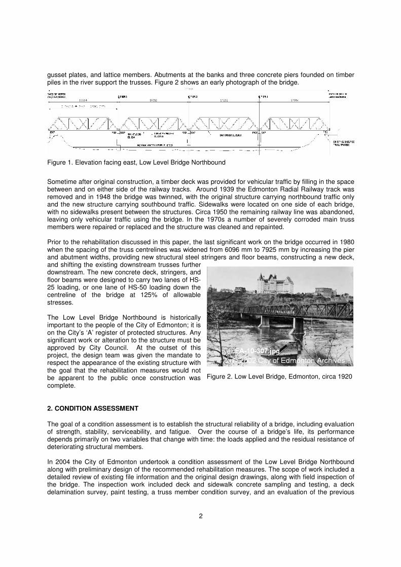
The Low Level Bridge Northbound in Edmonton, Canada, was originally designed for trains of the Grand Trunk Pacific Railway and was the first railway bridge to cross the North Saskatchewan River at Edmonton. Constructed between 1898 and 1900, the structure is a riveted steel through-truss with four equal spans of 53 metres, as illustrated in Figure 1. When originally constructed, it carried a Grand Trunk track centered between the trusses along with a second track for the Edmonton Radial Railway streetcar offset from the centreline. The specified railway loading was CN55%-2-8-0, which is approximately equivalent to the current Cooper E50 loading. The trusses are built up from structural steel angles, cover plates,
2
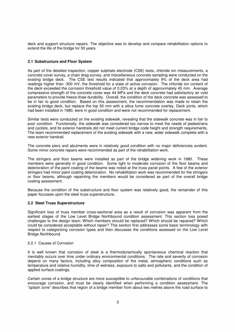
gusset plates, and lattice members. Abutments at the banks and three concrete piers founded on timber piles in the river support the trusses. Figure 2 shows an early photograph of the bridge.
Sometime after original construction, a timber deck was provided for vehicular traffic by filling in the space between and on either side of the railway tracks. Around 1939 the Edmonton Radial Railway track was removed and in 1948 the bridge was twinned, with the original structure carrying northbound traffic only and the new structure carrying southbound traffic. Sidewalks were located on one side of each bridge, with no sidewalks present between the structures. Circa 1950 the remaining railway line was abandoned, leaving only vehicular traffic using the bridge. In the 1970s a number of severely corroded main truss members were repaired or replaced and the structure was cleaned and repainted. Prior to the rehabilitation discussed in this paper, the last significant work on the bridge occurred in 1980 when the spacing of the truss centrelines was widened from 6096 mm to 7925 mm by increasing the pier and abutment widths, providing new structural steel stringers and floor beams, constructing a new deck, and shifting the existing downstream trusses further downstream. The new concrete deck, stringers, and floor beams were designed to carry two lanes of HS-25 loading, or one lane of HS-50 loading down the centreline of the bridge at 125% of allowable stresses. The Low Level Bridge Northbound is historically important to the people of the City of Edmonton; it is on the City’s ‘A’ register of protected structures. Any significant work or alteration to the structure must be approved by City Council. At the outset of this project, the design team was given the mandate to respect the appearance of the existing structure with the goal that the rehabilitation measures would not be apparent to the public once construction was complete.
2. CONDITION ASSESSMENT
The goal of a condition assessment is to establish the structural reliability of a bridge, including evaluation of strength, stability, serviceability, and fatigue. Over the course of a bridge’s life, its performance depends primarily on two variables that change with time: the loads applied and the residual resistance of deteriorating structural members. In 2004 the City of Edmonton undertook a condition assessment of the Low Level Bridge Northbound along with preliminary design of the recommended rehabilitation measures. The scope of work included a detailed review of existing file information and the original design drawings, along with field inspection of the bridge. The inspection work included deck and sidewalk concrete sampling and testing, a deck delamination survey, paint testing, a truss member condition survey, and an evaluation of the previous
Figure 2. Low Level Bridge, Edmonton, circa 1920
Figure 1. Elevation facing east, Low Level Bridge Northbound
3
deck and support structure repairs. The objective was to develop and compare rehabilitation options to extend the life of the bridge for 50 years.
2.1 Substructure and Floor System
As part of the detailed inspection, copper sulphate electrode (CSE) tests, chloride ion measurements, a concrete cover survey, a chain drag survey, and miscellaneous concrete sampling were conducted on the existing bridge deck. The CSE test results indicated that approximately 9% of the deck area had readings higher than -300 mV, the threshold for a state of active corrosion. The chloride ion content of the deck exceeded the corrosion threshold value of 0.03% at a depth of approximately 45 mm. Average compressive strength of the concrete cores was 44 MPa and the deck concrete had satisfactory air void parameters to provide freeze-thaw durability. Overall, the condition of the deck concrete was assessed to be in fair to good condition. Based on this assessment, the recommendation was made to retain the existing bridge deck, but replace the top 50 mm with a silica fume concrete overlay. Deck joints, which had been installed in 1980, were in good condition and were not recommended for replacement. Similar tests were conducted on the existing sidewalk, revealing that the sidewalk concrete was in fair to poor condition. Functionally, the sidewalk was considered too narrow to meet the needs of pedestrians and cyclists, and its exterior handrails did not meet current bridge code height and strength requirements. The team recommended replacement of the existing sidewalk with a new, wider sidewalk complete with a new exterior handrail. The concrete piers and abutments were in relatively good condition with no major deficiencies evident. Some minor concrete repairs were recommended as part of the rehabilitation work. The stringers and floor beams were installed as part of the bridge widening work in 1980. These members were generally in good condition. Some light to moderate corrosion of the floor beams and deterioration of the paint coating of the beams was noted at the truss panel points. A few of the exterior stringers had minor paint coating deterioration. No rehabilitation work was recommended for the stringers or floor beams, although repainting the members would be considered as part of the overall bridge coating assessment. Because the condition of the substructure and floor system was relatively good, the remainder of this paper focusses upon the steel truss superstructure. 2.2 Steel Truss Superstructure Significant loss of truss member cross-sectional area as a result of corrosion was apparent from the earliest stages of the Low Level Bridge Northbound condition assessment. This section loss posed challenges to the design team: Which members should be replaced? Which should be repaired? Which could be considered acceptable without repair? This section first addresses some basic terminology with respect to categorizing corrosion types and then discusses the conditions assessed on the Low Level Bridge Northbound.
2.2.1 Causes of Corrosion
It is well known that corrosion of steel is a thermodynamically spontaneous chemical reaction that inevitably occurs over time under ordinary environmental conditions. The rate and severity of corrosion depend on many factors, including alloy composition of the metal, atmospheric conditions such as temperature and relative humidity, time of wetness, exposure to salts and pollutants, and the condition of applied surface coatings. Certain zones of a bridge structure are more susceptible to unfavourable combinations of conditions that encourage corrosion, and must be clearly identified when performing a condition assessment. The “splash zone” describes that region of a bridge member from about two metres above the road surface to
4
about two metres below. Debris such as gravel and sand is thrown by vehicles, causing damage to protective coatings. Water and road salts are subsequently splashed onto the exposed steel. Other zones of concern are areas that tend to collect and pool water for extended periods of time, including the bottom chords of steel members and drainage systems plugged with debris. It is possible for severe deterioration to occur in these zones while other areas on the same bridge coincidentally show little or no evidence of corrosion.
2.2.2 Types of Corrosion
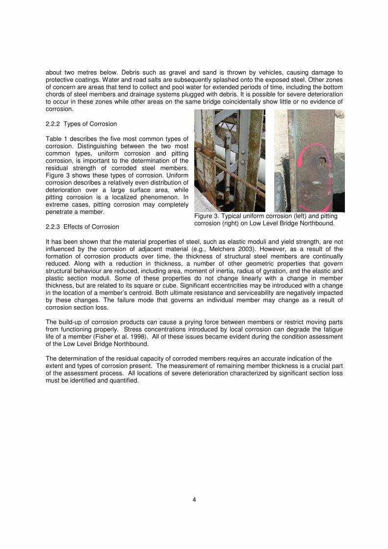
Table 1 describes the five most common types of corrosion. Distinguishing between the two most common types, uniform corrosion and pitting corrosion, is important to the determination of the residual strength of corroded steel members. Figure 3 shows these types of corrosion. Uniform corrosion describes a relatively even distribution of deterioration over a large surface area, while pitting corrosion is a localized phenomenon. In extreme cases, pitting corrosion may completely penetrate a member.
2.2.3 Effects of Corrosion
It has been shown that the material properties of steel, such as elastic moduli and yield strength, are not influenced by the corrosion of adjacent material (e.g., Melchers 2003). However, as a result of the formation of corrosion products over time, the thickness of structural steel members are continually reduced. Along with a reduction in thickness, a number of other geometric properties that govern structural behaviour are reduced, including area, moment of inertia, radius of gyration, and the elastic and plastic section moduli. Some of these properties do not change linearly with a change in member thickness, but are related to its square or cube. Significant eccentricities may be introduced with a change in the location of a member’s centroid. Both ultimate resistance and serviceability are negatively impacted by these changes. The failure mode that governs an individual member may change as a result of corrosion section loss. The build-up of corrosion products can cause a prying force between members or restrict moving parts from functioning properly. Stress concentrations introduced by local corrosion can degrade the fatigue life of a member (Fisher et al. 1998). All of these issues became evident during the condition assessment of the Low Level Bridge Northbound. The determination of the residual capacity of corroded members requires an accurate indication of the extent and types of corrosion present. The measurement of remaining member thickness is a crucial part of the assessment process. All locations of severe deterioration characterized by significant section loss must be identified and quantified.
Figure 3. Typical uniform corrosion (left) and pitting corrosion (right) on Low Level Bridge Northbound.
5
The often subjective nature of assessing the extent of corrosion damage in steel bridges has been identified by previous studies as a major issue that hinders the determination of structural reliability (Akgul and Frangopol, 2004; Estes and Frangopol, 1999). The high variability of corrosion development makes it difficult to establish clear, consistent procedures for assessing damage. Even more difficult is the task of quantitatively forecasting the rate and extent of future corrosion development. While models have been proposed to predict the expected corrosion penetration of steel bridge girders (Kayser and Nowak 1989; Cheung and Li 2001), the accuracy of these models depends on highly variable, often unavailable environmental data. A well-formulated prediction model simply does not exist. Thus a condition assessment typically requires a quantitative analysis based on partially subjective data. 2.2.4. Condition of Low Level Bridge Trusses Field inspections revealed that paint on the steel trusses had signs of deterioration expected after 28 years of service. The paint film was brittle, with large portions of the truss having exposed bare metal, particularly along the west bottom chord. Within the splash zones, the paint provided little or no protection against further corrosion. Repair of the existing paint system was not possible; the team determined that the entire bridge structure should be gritblasted clean to base metal and repainted. A calcium sulfonate penetrant sealer and topcoat system was proposed as the best option to address crevice corrosion and provide long-term protection for the structure. Inspection of the truss members revealed severe crevice corrosion of the bottom chords throughout their length. The west bottom chords were in the worst condition. These chords are not protected by a sidewalk above and are exposed to roadway splash from both the northbound bridge and the adjacent southbound bridge. The east bottom chords are partially protected by the existing sidewalk of the northbound bridge, but severe corrosion was found at the truss panel points where the vertical members pass through formed holes in the sidewalk concrete. Due to the amount of corrosion and pack rust on the bottom chords it was difficult to accurately assess the amount of section loss that occurred. The cross-sectional area loss of the bottom chords at particular crevice corrosion locations was estimated to be approximately 25%. The top chord members and the steel bracing between the chords were generally in good condition, since they are outside the traffic splash zone. The vertical and diagonal truss members were in good to fair condition above the splash zone, but were in poor condition below the splash zone. Several locations
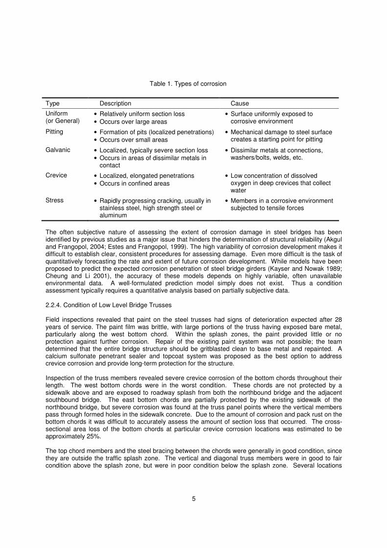
Type Description Cause
Uniform (or General)
• Relatively uniform section loss
• Occurs over large areas
• Surface uniformly exposed to corrosive environment
Pitting • Formation of pits (localized penetrations)
• Occurs over small areas
• Mechanical damage to steel surface creates a starting point for pitting
Galvanic • Localized, typically severe section loss
• Occurs in areas of dissimilar metals in contact
• Dissimilar metals at connections, washers/bolts, welds, etc.
Crevice • Localized, elongated penetrations
• Occurs in confined areas
• Low concentration of dissolved oxygen in deep crevices that collect water
Stress • Rapidly progressing cracking, usually in stainless steel, high strength steel or aluminum
• Members in a corrosive environment subjected to tensile forces
Table 1. Types of corrosion
6
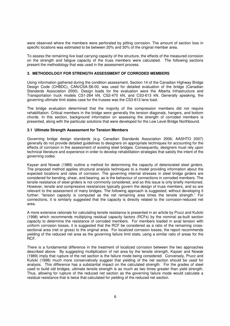
were observed where the members were perforated by pitting corrosion. The amount of section loss in specific locations was estimated to be between 20% and 30% of the original member area. To assess the remaining live load carrying capacity of the structure, the effects of the measured corrosion on the strength and fatigue capacity of the truss members were calculated. The following sections present the methodology that was used in the assessment process.
3. METHODOLOGY FOR STRENGTH ASSESSMENT OF CORRODED MEMBERS
Using information gathered during the condition assessment, Section 14 of the Canadian Highway Bridge Design Code (CHBDC), CAN/CSA-S6-00, was used for detailed evaluation of the bridge (Canadian Standards Association 2000). Design loads for the evaluation were the Alberta Infrastructure and Transportation truck models CS1-264 kN, CS2-470 kN, and CS3-613 kN. Generally speaking, the governing ultimate limit states case for the trusses was the CS3-613 lane load. The bridge evaluation determined that the majority of the compression members did not require rehabilitation. Critical members in the bridge were generally the tension diagonals, hangers, and bottom chords. In this section, background information on assessing the strength of corroded members is presented, along with the particular solutions that were developed for the Low Level Bridge Northbound. 3.1 Ultimate Strength Assessment for Tension Members Governing bridge design standards (e.g. Canadian Standards Association 2006; AASHTO 2007) generally do not provide detailed guidelines to designers on appropriate techniques for accounting for the effects of corrosion in the assessment of existing steel bridges. Consequently, designers must rely upon technical literature and experience in order to develop rehabilitation strategies that satisfy the intent of the governing codes. Kayser and Nowak (1989) outline a method for determining the capacity of deteriorated steel girders. The proposed method applies structural analysis techniques to a model providing information about the expected locations and rates of corrosion. The governing internal stresses in steel bridge girders are considered for bending, shear, and bearing, as is the behaviour of connections in corroded members. The tensile resistance of steel girders is not commonly considered, and so this issue is only briefly mentioned. However, tensile and compressive resistances typically govern the design of truss members, and so are relevant to the assessment of many bridges. The following approach is suggested, without developing it further: “tension capacity is computed as the net remaining area times the tensile strength.” For connections, it is similarly suggested that the capacity is directly related to the corrosion-reduced net area. A more extensive rationale for calculating tensile resistance is presented in an article by Prucz and Kulicki (1998) which recommends multiplying residual capacity factors (RCFs) by the nominal as-built section capacity to determine the resistance of corroded members. For members loaded in axial tension with uniform corrosion losses, it is suggested that the RCF be considered as a ratio of the remaining cross-sectional area (net or gross) to the original area. For localized corrosion losses, the report recommends yielding of the reduced net area as the governing failure limit state, using a similar ratio of areas for the RCF. There is a fundamental difference in the treatment of localized corrosion between the two approaches described above. By suggesting multiplication of net area by the tensile strength, Kayser and Nowak (1989) imply that rupture of the net section is the failure mode being considered. Conversely, Prucz and Kulicki (1998) much more conservatively suggest that yielding of the net section should be used for analysis. This difference has a substantial impact on the calculated strength. For the grades of steel used to build old bridges, ultimate tensile strength is as much as two times greater than yield strength. Thus, allowing for rupture of the reduced net section as the governing failure mode would calculate a residual resistance that is twice that calculated for yielding of the reduced net section.
7
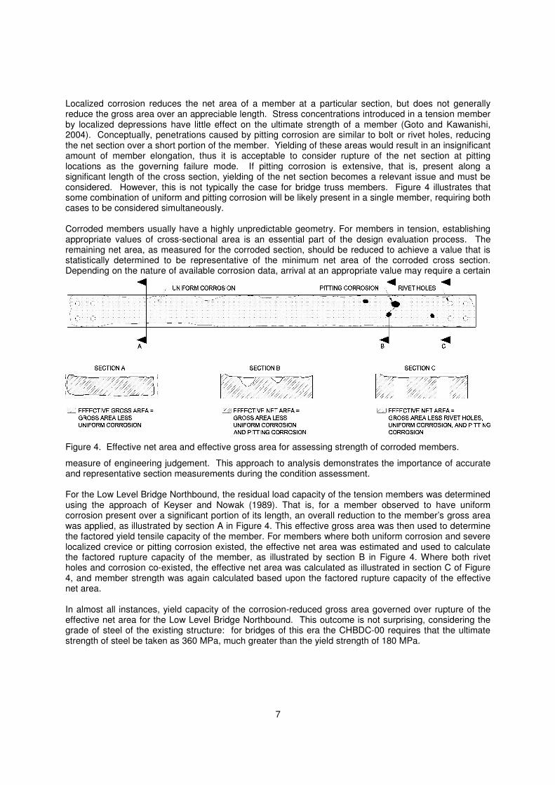
Localized corrosion reduces the net area of a member at a particular section, but does not generally reduce the gross area over an appreciable length. Stress concentrations introduced in a tension member by localized depressions have little effect on the ultimate strength of a member (Goto and Kawanishi, 2004). Conceptually, penetrations caused by pitting corrosion are similar to bolt or rivet holes, reducing the net section over a short portion of the member. Yielding of these areas would result in an insignificant amount of member elongation, thus it is acceptable to consider rupture of the net section at pitting locations as the governing failure mode. If pitting corrosion is extensive, that is, present along a significant length of the cross section, yielding of the net section becomes a relevant issue and must be considered. However, this is not typically the case for bridge truss members. Figure 4 illustrates that some combination of uniform and pitting corrosion will be likely present in a single member, requiring both cases to be considered simultaneously. Corroded members usually have a highly unpredictable geometry. For members in tension, establishing appropriate values of cross-sectional area is an essential part of the design evaluation process. The remaining net area, as measured for the corroded section, should be reduced to achieve a value that is statistically determined to be representative of the minimum net area of the corroded cross section. Depending on the nature of available corrosion data, arrival at an appropriate value may require a certain
measure of engineering judgement. This approach to analysis demonstrates the importance of accurate and representative section measurements during the condition assessment. For the Low Level Bridge Northbound, the residual load capacity of the tension members was determined using the approach of Keyser and Nowak (1989). That is, for a member observed to have uniform corrosion present over a significant portion of its length, an overall reduction to the member’s gross area was applied, as illustrated by section A in Figure 4. This effective gross area was then used to determine the factored yield tensile capacity of the member. For members where both uniform corrosion and severe localized crevice or pitting corrosion existed, the effective net area was estimated and used to calculate the factored rupture capacity of the member, as illustrated by section B in Figure 4. Where both rivet holes and corrosion co-existed, the effective net area was calculated as illustrated in section C of Figure 4, and member strength was again calculated based upon the factored rupture capacity of the effective net area. In almost all instances, yield capacity of the corrosion-reduced gross area governed over rupture of the effective net area for the Low Level Bridge Northbound. This outcome is not surprising, considering the grade of steel of the existing structure: for bridges of this era the CHBDC-00 requires that the ultimate strength of steel be taken as 360 MPa, much greater than the yield strength of 180 MPa.
Figure 4. Effective net area and effective gross area for assessing strength of corroded members.
8
3.2 Fatigue Strength Assessment
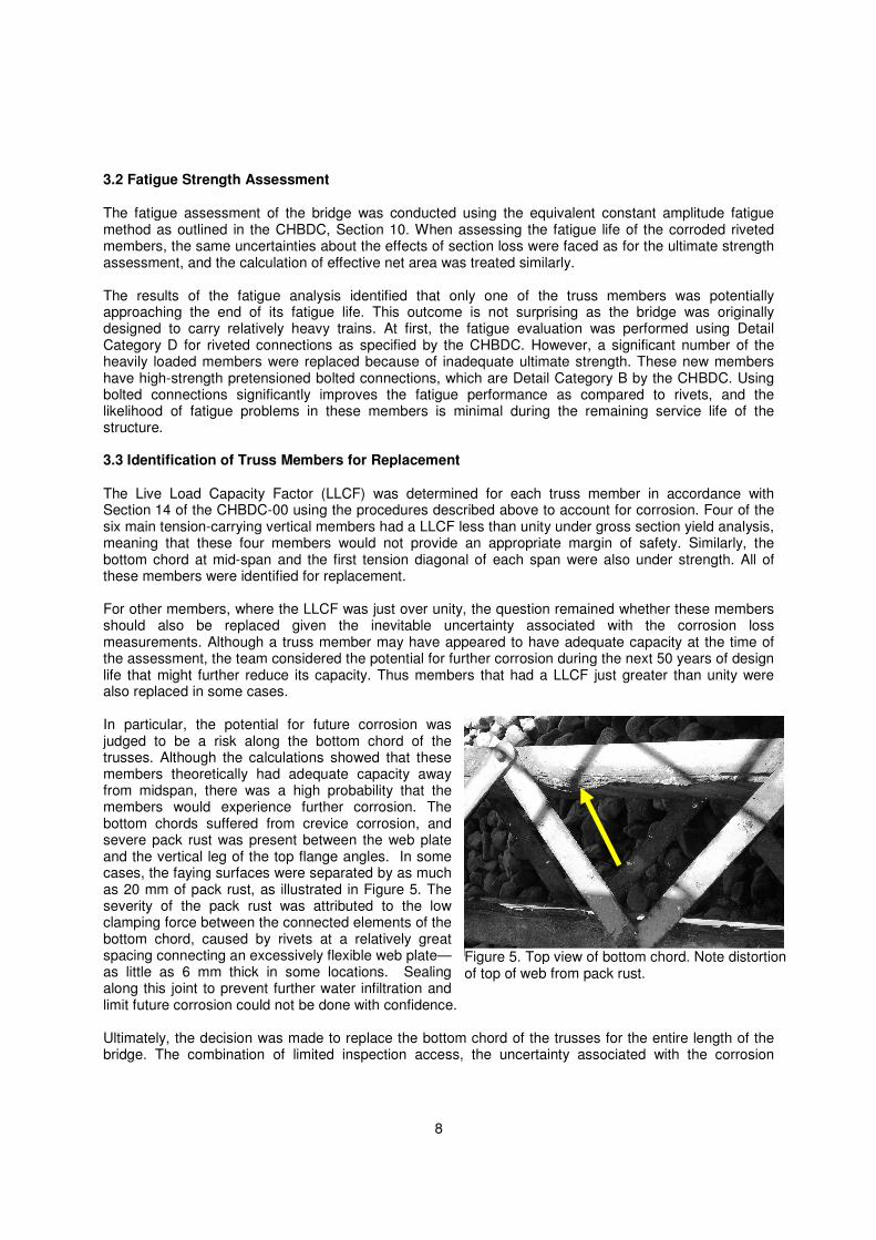
The fatigue assessment of the bridge was conducted using the equivalent constant amplitude fatigue method as outlined in the CHBDC, Section 10. When assessing the fatigue life of the corroded riveted members, the same uncertainties about the effects of section loss were faced as for the ultimate strength assessment, and the calculation of effective net area was treated similarly. The results of the fatigue analysis identified that only one of the truss members was potentially approaching the end of its fatigue life. This outcome is not surprising as the bridge was originally designed to carry relatively heavy trains. At first, the fatigue evaluation was performed using Detail Category D for riveted connections as specified by the CHBDC. However, a significant number of the heavily loaded members were replaced because of inadequate ultimate strength. These new members have high-strength pretensioned bolted connections, which are Detail Category B by the CHBDC. Using bolted connections significantly improves the fatigue performance as compared to rivets, and the likelihood of fatigue problems in these members is minimal during the remaining service life of the structure. 3.3 Identification of Truss Members for Replacement The Live Load Capacity Factor (LLCF) was determined for each truss member in accordance with Section 14 of the CHBDC-00 using the procedures described above to account for corrosion. Four of the six main tension-carrying vertical members had a LLCF less than unity under gross section yield analysis, meaning that these four members would not provide an appropriate margin of safety. Similarly, the bottom chord at mid-span and the first tension diagonal of each span were also under strength. All of these members were identified for replacement. For other members, where the LLCF was just over unity, the question remained whether these members should also be replaced given the inevitable uncertainty associated with the corrosion loss measurements. Although a truss member may have appeared to have adequate capacity at the time of the assessment, the team considered the potential for further corrosion during the next 50 years of design life that might further reduce its capacity. Thus members that had a LLCF just greater than unity were also replaced in some cases. In particular, the potential for future corrosion was judged to be a risk along the bottom chord of the trusses. Although the calculations showed that these members theoretically had adequate capacity away from midspan, there was a high probability that the members would experience further corrosion. The bottom chords suffered from crevice corrosion, and severe pack rust was present between the web plate and the vertical leg of the top flange angles. In some cases, the faying surfaces were separated by as much as 20 mm of pack rust, as illustrated in Figure 5. The severity of the pack rust was attributed to the low clamping force between the connected elements of the bottom chord, caused by rivets at a relatively great spacing connecting an excessively flexible web plate—as little as 6 mm thick in some locations. Sealing along this joint to prevent further water infiltration and limit future corrosion could not be done with confidence. Ultimately, the decision was made to replace the bottom chord of the trusses for the entire length of the bridge. The combination of limited inspection access, the uncertainty associated with the corrosion
Figure 5. Top view of bottom chord. Note distortion of top of web from pack rust.

9
measurements, and the difficultly in controlling further deterioration of the existing members led to this decision. Using modern 350WT steel while maintaining the same cross-sectional area of the existing members, the strength and fatigue resistance of the new members enables them to carry Alberta legal loads. Reuse of the existing gusset plates, which were in relatively good condition, permitted the existing deck and floor system to be maintained and offered considerable cost savings. 4. OTHER DESIGN AND CONSTRUCTION CHALLENGES 4.1 Widened sidewalk One of the most significant challenges faced by the design team was that the new, wider sidewalk would cause an overload in approximately half of the existing, corroded main truss members. The new sidewalk is nearly twice as wide as the original sidewalk, resulting in increased loads on the existing connections to the truss members. An innovative idea solved the problem: a small steel strap plate was slotted between the angles of the existing built-up vertical truss members, allowing the sidewalk forces to bypass the truss members and transfer the load directly into the floor beams. Figure 6 illustrates the new sidewalk system. The new, wider sidewalk dramatically improves the experience of pedestrians and cyclists using this bridge as part of Edmonton’s River Valley trail system. 4.2 Historical Significance
At the outset of the project, the design team was given the mandate to respect the appearance of the existing structure and to ensure that the rehabilitation measures would not be apparent to the public once construction was complete. The original truss diagonals and verticals are riveted, built-up “I” sections consisting of angles that form the flanges and lattice plates that form the web (see Figure 6). This fabrication method, common in the era that the Low Level Bridge Northbound was built, gives the truss members a unique appearance that had to be maintained in the replacement members. Discussions with local fabricators revealed that it would be expensive and time consuming to fabricate the replacement members using riveted or bolted built-up lattice members, due principally to the intensive amount of labour involved. As a more economical alternate, new members were constructed to the same cross-sectional dimensions as the original, but were fabricated instead using plates welded together to form the flanges and webs. Figure 6 shows how the original lattice pattern of the original webs was duplicated using plasma-cut holes in the new web plate, a modern construction technique that maintains the historical appearance of the members. A similar approach was used to imitate the original appearance of the bridge railing.
Figure 6. Drawing and photograph of widened sidewalk. Note plasma-cut railings and truss webs to emulate original lattice construction.
10
4.3 Truss Member Replacement Techniques
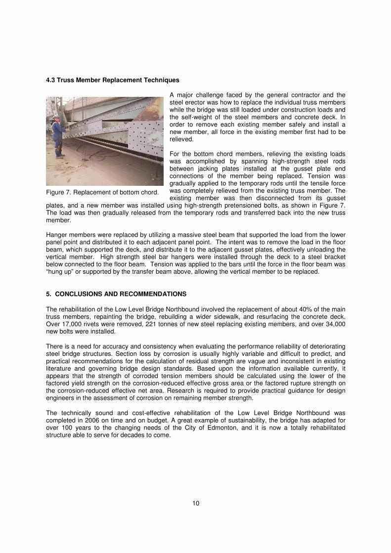
A major challenge faced by the general contractor and the steel erector was how to replace the individual truss members while the bridge was still loaded under construction loads and the self-weight of the steel members and concrete deck. In order to remove each existing member safely and install a new member, all force in the existing member first had to be relieved. For the bottom chord members, relieving the existing loads was accomplished by spanning high-strength steel rods between jacking plates installed at the gusset plate end connections of the member being replaced. Tension was gradually applied to the temporary rods until the tensile force was completely relieved from the existing truss member. The existing member was then disconnected from its gusset
plates, and a new member was installed using high-strength pretensioned bolts, as shown in Figure 7. The load was then gradually released from the temporary rods and transferred back into the new truss member. Hanger members were replaced by utilizing a massive steel beam that supported the load from the lower panel point and distributed it to each adjacent panel point. The intent was to remove the load in the floor beam, which supported the deck, and distribute it to the adjacent gusset plates, effectively unloading the vertical member. High strength steel bar hangers were installed through the deck to a steel bracket below connected to the floor beam. Tension was applied to the bars until the force in the floor beam was “hung up” or supported by the transfer beam above, allowing the vertical member to be replaced.
5. CONCLUSIONS AND RECOMMENDATIONS
The rehabilitation of the Low Level Bridge Northbound involved the replacement of about 40% of the main truss members, repainting the bridge, rebuilding a wider sidewalk, and resurfacing the concrete deck. Over 17,000 rivets were removed, 221 tonnes of new steel replacing existing members, and over 34,000 new bolts were installed.
There is a need for accuracy and consistency when evaluating the performance reliability of deteriorating steel bridge structures. Section loss by corrosion is usually highly variable and difficult to predict, and practical recommendations for the calculation of residual strength are vague and inconsistent in existing literature and governing bridge design standards. Based upon the information available currently, it appears that the strength of corroded tension members should be calculated using the lower of the factored yield strength on the corrosion-reduced effective gross area or the factored rupture strength on the corrosion-reduced effective net area. Research is required to provide practical guidance for design engineers in the assessment of corrosion on remaining member strength.
The technically sound and cost-effective rehabilitation of the Low Level Bridge Northbound was completed in 2006 on time and on budget. A great example of sustainability, the bridge has adapted for over 100 years to the changing needs of the City of Edmonton, and it is now a totally rehabilitated structure able to serve for decades to come.
Figure 7. Replacement of bottom chord.
11
ACKNOWLEDGEMENTS
The authors acknowledge the entire project team for the success of the rehabilitation work, including The City of Edmonton, Alberco Construction Ltd., Midwest Constructors, Supreme Steel Bridge Division, and Clara Industries. In particular, the efforts of Mr. Mike Marlow and Mr. Jason Meliefste with The City of Edmonton Transportation Department are acknowledged with thanks.
REFERENCES
AASHTO. 2007. LRFD Bridge Design Specifications, SI Units, 4th Edition. American Association of State Highway and Transportation Officials, Washington, DC.
Akgul, F., and Frangopol, D.M. 2004. “Lifetime Performance Analysis of Existing Steel Girder Bridge Superstructures,” Journal of Structural Engineering, ASCE, 130: 1875-1888.
Canadian Standards Association. 2000. CAN/CSA-S6-00, Canadian Highway Bridge Design Code. Missassauga, ON.
Canadian Standards Association. 2006. CAN/CSA-S6-06, Canadian Highway Bridge Design Code. Missassauga, ON.
Cheung, M.S., and Li, W.C. 2001. “Serviceability Reliability of Corroded Steel Bridges,” Canadian Journal of Civil Engineering, 28: 419-424.
Estes, A.C., and Frangopol, D.M. 1999. Repair Optimization of Highway Bridges Using System Reliability Approach, Journal of Structural Engineering, ASCE, 125: 766-775.
Fisher, J.W., Kulak, G.L., and Smith, I.F.C. 1998. A Fatigue Primer for Structural Engineers. National Steel Bridge Alliance, AISC, Chicago, IL.
Goto, Y., and Kawanishi, N. 2004. Analysis to Predict Long-Term Mechanical Performance of Steel Structures with Histories of Corrosion and Repair. Journal of Structural Engineering, ASCE, 130: 1578-1585.
Kayser, J.R., and Nowak, A.S. 1989. Capacity Loss Due to Corrosion in Steel-Girder Bridges. Journal of Structural Engineering, ASCE, 115: 1525-1537.
Melchers, R.E. 2003. Probabilistic Models for Corrosion in Structural Reliability Assessment- Part 1: Empirical Models. Journal of Offshore Mechanics and Artic Engineering. ASME, 125: 265-271.
Prucz, Z. and Kulicki, J.M. 1998. Accounting for Effects of Corrosion Section Loss in Steel Bridges. Transportation Research Record, No. 1624: 101-109.