Embed Size (px)
Citation preview

REGULATORY INFORMATION DISTRIBUTION SYSTEM (RIDS) DISTRIBUTION FOR INCOMING MATERIAL 50-261
REC: CASE E B ORB: UTLEY E E DOCDATE: 01/20/78 NRC CAROLINA PWR & LIGHT DATE RCVD: 01/23/78
DOCTYPE: LETTER NOTARIZED: NO COPIES RECEIVED SUBJECT: LTR 1 ENCL 1 RESPONSE TO NRC LTR DTD 12/15/77... FORWARDING RESPONSE TO QUESTIONNAIRE CONCERNING STANDBY DIESEL GENERATOR UNITS...W/ATT SHEET OF PERSON RESPONSIBLE FOR ANY FOLLOW-UP COMMUNICATIONS.
PLANT NAME:H B ROBINSON - UNIT 2 REVIEWER INITIAL: XJM DISTRIBUTOR INITIAL:
****++*****++**+* DISTRIBUTION OF THIS MATERIAL IS AS FOLLOWS ++++************
DISTRIBUTION OF "RELIABILITY OF STANDBY DIESEL GENERATOR UNITS" PER J. (DISTRIBUTION CODE A014)
FOR ACTION: BRANCH CHIEF REID**W/7 ENCL
INTERNAL: C: EGF L NRC PDR**W/ENCL .C : WOELD**W/*ENC:L
HANAUER**W/ENCL CHECK**W/ENCL EISENHUT**W/ENCL SHAO**W/ENCL BAER**W/ENCL BUTLER**W/ENCL GRIMES**W/ENCL J IOLLINS**W/ENCL J. MCGOUNH**W/ENCL F. CLEMENSON**W/ENCL
EXTERNAL: LPDR*S HARTSVIOLLE, SC**W/ENCL
TIHC**W/ENCL NSIHC**W/ENCL ACRS CAT B**W/16 ENCL
DISTRIBUTION: LTR 40 ENCL 40 CONTROL NBR: 780230056 SIZE: NP+SP+1/4"I
ACRSCATBW/16THE ENDENC DISTIBUION LT 40 NCL40 ONTOL NR: 802005

CP&L AEGULr0,7Y DICKF Carolina Power & Light Company c
January 20, 1978
-0 02 2 FILE: NG-3514 (R) SERIAL: GD-78-176
Mr. Edson G. Case, Acting Director Office of Nuclear Reactor Regulation U. S. Nuclear Regulatory Commission VAN 31978 Washington, D.C. 20555 los
H. B. ROBINSON STEAM ELECTRIC PLANT UNIT NO. 2 DOCKET NO. 50-261
FACILITY OPERATING LICENSE NO. DPR-23 STANDBY DIESEL GENERATOR UNITS QUESTIONNAIRE
Dear Mr. Case:
In the letter of December 15, 1977, from Mr. Karl R. Goller, it was requested that the enclosed questionnaire on Standby Diesel Generator Units be completed and returned to your office. Enclosed also is a separate sheet with the name, address, and phone number of the person responsible for responding to any follow-up communications concerning this questionnaire.
Yours very truly,
Senior Vice President Power Supply
DCS:as
Enclosures
7802 0056
336 Favetteville Street.* P. O. Box 1551 *Raleiah. N. C. 27602

For response to questions concerning the H. B. Robinson Unit No. 2 Standby Diesel Generator Units, please contact:
Mr. R. B. .Starkey, Jr., Manager H. B. Robinson Steam Electric Plant
Post Office Box 790 Hartsville, South Carolina 29550

Questionnaire
for
NUCLEAR REGULATORY COMMISSION RELIABILITY STUDY
of
Standby Diesel Generator Units
Date Questionnaire Completed: January 6, 1978
-Plant Hame: H. B. Robinson Unit No. 2
Di-.e e.il inufacturer: Fairbanks Morse Model: 38TD-8 1/8
Number of Units: 2
Size Kw/Unit: 2500 Rated Speed: 900
Average Operating Hours Per Unit to Date: 497.3
DIESEL GENERATOR STATUS
A. Engine:
1. Problems are caused chiefly by (give estimated number)
a. Defective parts 2 b. Installation errors: 1 c. Failure of system to respond properly in
function or sequence: . 8 d. Faulty adjustment: 0
2. .Would more stringent inspection and testing requirements
.. .during acceptance or preoperational tests significantly -mprove the diesel-generator power plant performance?
Yes _No X
,3. Starting Systems (indicate which):
1. Air-to-cylinder cranking. X
Air cranking motor' Mfr. N/A Model No. N/A
Electric cranking motor Mfr. N/A Model No. N/A

-2
2. If air cranking, then:
Give size of starting air tank: Length 96" Diameter 30"
Normal standby air tank pressure 225-250 psi.
Is pressure reducer used? Yes No x Reducer pipe size? N/A inches.
Starting air control admission valve pipe size in air piping system, 1 1/2 inches. (2 Valves)
Minimum air tank pressure for engine cranking 150 psi.
Number of five-second cranking periods between above pressures with no tank recharging 8
Number of air tanks per engine 1
Can starting air tanks serve more than one engine? Yes x No _
Is air pipe to engine from top of air tank? Yes X No
Does starting air tank have water condensate drain? Yes x No Also air dryer between compressor and tank. Does starting air pipe have water condensate trap and drain near engine? "Yes No X
Is starting air piping horizontal? Yes X No X Some vertical runs also.
Does it slant toward drain? Yes No x
If water condensate drains are provided, then is draining:
a. Automatic through float valve? Yes No x
b. Manual by hand valve? Yes x No c. If manual, then is draining water condensate done:

-3
daily? weekly? x monthly? before each start if manual? no procedure?
Is dirt and rust filter provided in starting air pipe? Yes X Ho
If provided, where installed? Before solenoid valves and before
engine (3 total)
How is it cleaned? Remove screen and clean
How often. and when? Refueling
Give pipe size of filter:. 1 1/2 inches.
How is it known whether filter is plugged or has high pressure drop? We have experienced no problems with these screens.
Is starting air pipe to engine positioned:
a. Below floor? N/A b. On the floor? x c. Overhead? X
Overhead and then down to diesel skid floor
What is air pressure drop from air tank to engine during cranking UN psi No provisions for checking
Give approximate length (nearest ten feet) of starting air piDe for individual engine or all engines from air tank to:
a. Nearest engine 30 feet b. Furthest enqine 100 feet

-4
Diameter of starting air pipe from: 1 -2-2
a. Air tank to starting valve inches b. At air starting valve 11_ inches (2 Valves) c. At engine 1, inches
What is the primary source of power for the starting air system? 480 volt safety related bus
Is there a duplicate and redundant motor and air compressor set? Yes No x
What is the time required to recharge one air tank? 4- minutes
Does starting air supply system have independent secondary power supply for-compressor? Yes No x
If yes, then by:
a. Gasoline engine? N/A
b. Motor driven? N/A c. Other? (SpecifyT N/A
3. If electric (Battery powered) cranking, then:
a. Battery charging: Continuous trickle charger N/A Intermittent charging N/A
If so, how is charging requirement determined?
-- Time cycle N/A Test N/A Other N/A
b. Battery used: Common Plant N/A Individual Unit N/A Other N/A
Starting cable size N/A ; Length: Battery to engine (longest) N/A

C. Fuel Oil System: Bulk Tank to Day Tank
1. Does the bulk tank to day tank fuel supply system (viz: pump, motor, etc.) have redundant independent power supplies? Yes x No
Does this system have a hand-operated emergency fuel pump? Yes No X
If yes, is this hand-operated pump and piping in immediate operating condition? Yes N/A NO N/A
2. Is there a water and sediment drain from the very bottom of the:
a. Bulk tank? Yes x No b. Day tank? Yes x No
3. Is the regular functional fuel oil outlet~slightly above (two to three inches) the bottom of the:
a. Bulk tank? Yes X No b. Day or integral tank? Yes X No
4. Is bottom of day tank and/or integral tank above all parts and piping of the enqine fuel injection systems? Yes No X
If yes,
Give approximate amount inches N/A feet N/A
5. Does the engine fuel system have a fuel bleed return line to the fuel day tank and/or integral tank? Yes x No
During extended operation, such as more than two to three hours, does the fuel in the day tank become: (yes or no)
a. Warm? No b. Hot? No (above 130*F)

-6
What is fuel oil return line size (nominal)?
a. Pipe size 3/4 inches b. Tubing size~77 inches
6. Do engine fuel oil filters have air bleed or vent valves readily accessible? Yes _ No
7. How is fuel transferred from day tank to engine-fuel system?
a. By gravity N/A b. Engine driven pump x c. Electric motor driven pump N/A d. Is a manual pump also provided for injection
system filling and/or air venting after servicing or replacement of parts in the fuel injection system? Yes X No
If yes, is the manual .pump in immediate operating condition? Yes X No
8. Type of fuel (e.g., #1, #2, #3', JP-4, etc.) #2
9. Approximate bulk tank capacity, 25,000 gallons. 200 in day tank
10. Typical frequency of refilling (weekly, monthly, etc.) 4-5 months
11. Typical refill (gallons), 5,000
D. Lube Oil System
1. Lube oil
a. Type URSA-ED-40 b. Viscosity 40
c. Specification number MIL-L-2104B
d. Oil change determined by:
Time interval: Yes No X
Give interval N/A monthly, yearly By oil analysis: Yes x No

-7
2. Lube oil filters are:
a. Full flow X b. Bypass N/A
c. Combination N/A
3. Interval and/or basis for changing filter cartridge:
a. Monthly N/A b. Yearly N/A c. By running time N/A hours
By oil analysis. Yes No X By pressure drop. Yes x No
f. Does provisions exist for changing cartridges during engine operation? Yes No x
4, Oil Pressure Monitoring
a. Normal operating pressure 35 psi b. Alarm 18 psi c. Shutdown 18 psI Non-emergency only
5. Oil temperature control:
a. By standby heater in engine sump 125 aF.
b. Heating means for maintaining standby temperature:
Direct in oil X Oil-to-water heat exchanger N/A Other (Specify) N/A
E. Cooling System - Engine Water
1. Temperature control by:
a. By thermostat in water? Yes x No
If yes, then:
Bypass thermostat? Yes X No
Throttle thermostat? Yes No X
-8
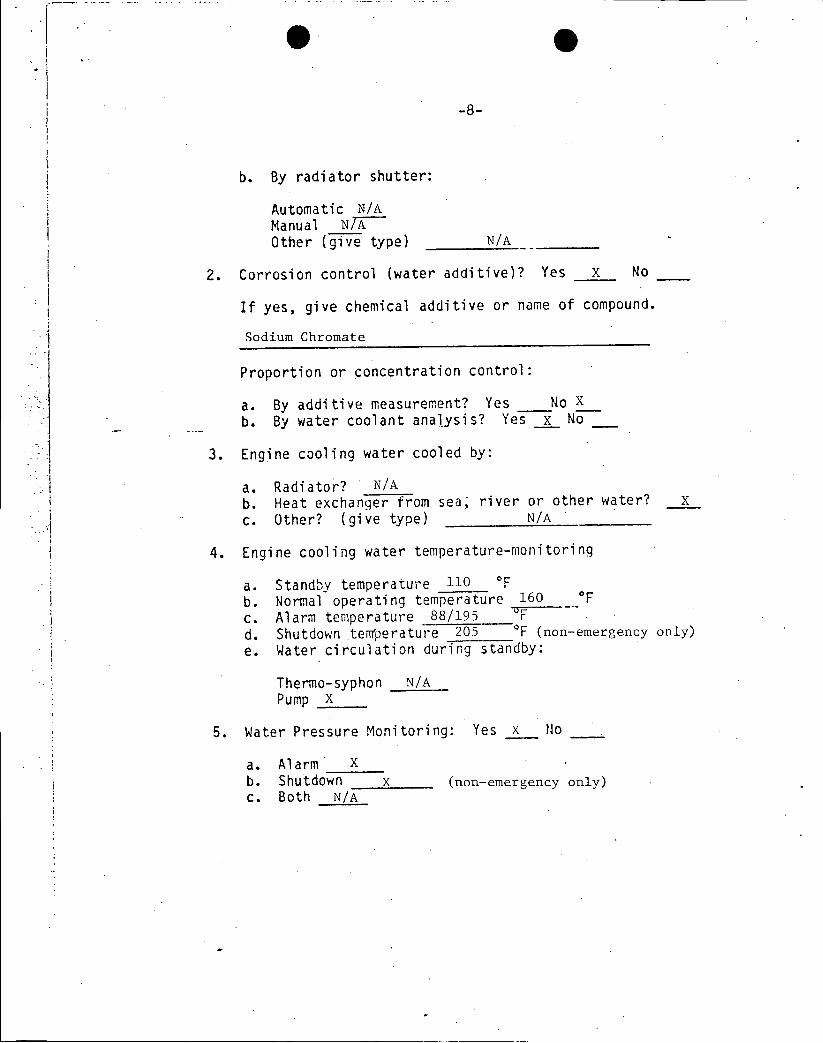
b. By radiator shutter:
Automatic N/A Manual NTX Other (give type) N/A
2. Corrosion control (water additive)? Yes X No
If yes, give chemical additive or name of compound.
Sodium Chromate
Proportion or concentration control:
a. By additive measurement? Yes No X
b. By water coolant analysis? Yes x No
3. Engine cooling water cooled by:
a. Radiator? N/A b. Heat exchanger from sea, river or other water? X c. Other? (give type) N/A
4. Engine cooling water temperature-monitoring
a. Standby temperature 110 OF
b. Normal operating temperature 160 F c. Alarm temperature 88/195 F d. Shutdown teperature 205 0F (non-emergency only) e. Water circulation during standby:
Thermo-syphon N/A Pump X
5. Water Pressure Monitoring: Yes X No
a. Alarm X b. Shutdown X (non-emergency only) c. Both N/A
* .g
-9
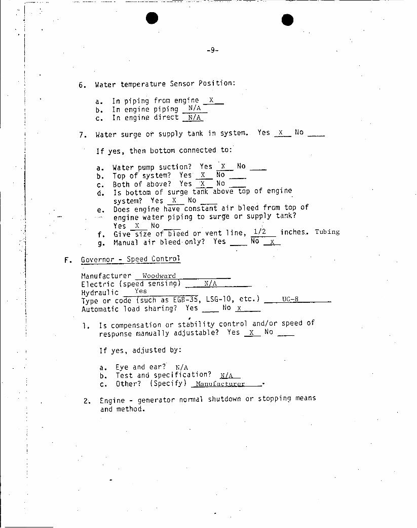
6. Water temperature Sensor Position:
a. In piping from engine x b. In engine piping N/A c. In engine direct N/A
7. Water surge or supply tank in system. Yes x No
If yes, then bottom connected to:
a. Water pump suction? Yes x No b. Top of system? Yes x No c. Both of above? Yes 'X No d. Is bottom of surge tank above top of engine
system? Yes X No e. Does engine have constant air bleed from top of
engine water piping to surge or supply tank? Yes X No
f. Give size of bleed or vent line, 1/2 inches.. Tubing
g. Manual air bleed-only? Yes No x
F. Governor - Speed Control
Manufacturer Woodward Electric (speed sensing) N/A Hydraulic Yes
Type or code (such as EGB-35, LSG-10, etc.) UG-8
Automatic load shari.ng? Yes No x tI
1. Is compensation or stability control and/or speed of
response manually adjustable? Yes x No
If yes, adjusted by:
a. Eye and ear? N/A b. Test and specification? N/A c. Other? (Specify) Manufacturer
2. Engine - generator normal shutdown or stoppinq means
and method.
-10
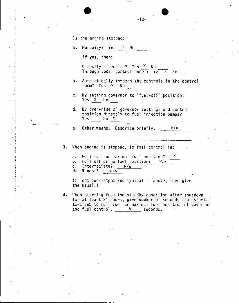
Is the engine stopped:
a. Manually? Yes X No
If yes, then:
Directly at engine? Yes X No Through local control panel? Yes X No
b. Automaticall through the controls in the control room? Yes No
c. By setting governor to "fuel-off" position? Yes X No
d. By over-ride of governor settings and control position directly to fuel injection pumps? Yes No X
e. Other means. Describe briefly. N/A
3. When engine is stopped, is fuel control in:
a. Full fuel or maximum fuel position? X b. Full off or no fuel position? N/A c. Intermediate? N/A d. Random? N/A
(If not consistent and typical in above, then give the usual.)
4. When starting from the standby condition after shutdown for at least 24 hours, give number of seconds from startto-crank to full fuel or maximum fuel position of governor and fuel control, 8 seconds.

G. Governor - Overspeed (shutdown)
1. Speed sensing?
a. Electrical N/A b. Flyball x c. Other (Specify) N/A
2. Fuel shutoff force generated by:
a. Spring? N/A b. Air? N/A
c. Hydraulic? N/A d. Electrical? Normal e. Other? (Spec i Manual Fuel &-rk
3. Overspeed sensing setting? (in terms of full speed)
a. 115% N/A b. 110% N/A c. Other-Tpecify) 112%
4. Is overspeed tripping set point tested periodically? Yes No x
If yes, then how often? N/A (yearly, monthly, etc.)
H. 1. Generator Mfr. Fairbanks Morse Model No. Type TG7T Single bearing cr'two bearings? Two Does generator have damper windings? Yes No X
2. Does generator have any obvious fault or difficulty? Yes No X
Is problem repetitive? Yes No x
If yes, then describe briefly. N/A
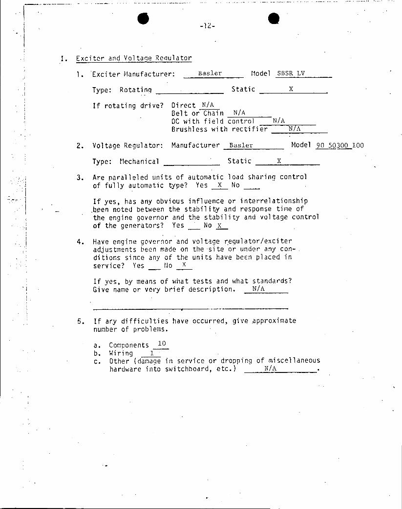
I. Exciter and Voltaqe Reoulator
1. Exciter Manufacturer: Basler Model SBSR LV
Type: Rotating . Static x
If rotating drive? Direct N/A Belt or Chain N/A DC with field control N/A Brushless with rectifier N/A
2. Voltage Regulator: Manufacturer Basler Model 90 50300 100
Type: Mechanical Static X
3. Are paralleled units of automatic load sharing control of fully automatic type? Yes X No
If yes, has any obvious influence or interrelationship -been noted between the stability and response time of the engine governor and the stability and voltage control of the generators? Yes No x
4. Have engine governor and voltage regulator/exciter adjustments been made on the -site or under any con-. ditions since any of the units have been placed in service? Yes 11o X
If yes, by means of what tests and what standards? Give name or very brief description. N/A
5. If ary difficulties have occurred, give approximate number of problems.
a. Components 10 b. Wiring 1 c. Other (damage in service or dropping of miscellaneous
hardware into switchboard, etc.) N/A

-13
J. Parallelinq: Engine-Generator Units
1. Do all units consistently have the proper voltage output? Yes X No
2. Do all units automatically share both the "real" or
in-phase load and also the reactive load reasonably well? Yes X No
3. At the same Kw load, are both the field and the armature
line currents of the several units consistently close
to the same value? Yes .X No
If no, approximate percent difference. N/A
4. Synchronizi nq
a. In automatic synchronizing do circuit breakers close
immediately after reaching full synchronous speed? Yes N/A No N/A
b. If "no" above then, does'speed of some units drift
slowly while failing to synchronize and close circuit breakers?
How many seconds? N/A
Occasionally N/A
Always N/A
Never N/A'
K. Switch Gear and Electrical Con (other than exciter/ voltage regulator)
1. If any difficulties have occurred, then give approximate
number of problems. None
a. Components N/A b. Wirina N/A c. Other (damage in service or dropping of miscellaneous
hardware into switchboard, etc.) N/A d. Design concept faults. That is, does the switch
gear and its controls perform the proper functions and in proper sequence and timing. Yes

2. a. Do the on-site diesel generator units and related support equipment have any storage battery power systems for any service whatsoever? Yes x No
b. Identify each storage battery power system associated with the on-site diesel generator uni.t and its function. 1 - Station batteries - normal control and field flashing
2 - emergency field flashing batteries - field flashing only
c. Does each system identified above adequately fulfill the service requirements for which it is intended? Yes x No
If no, briefly describe. N/A
d. Is there a DG battery maintenance program? Yes x No
L. Safety Shut downs
Give safety shut down settings compared to equilibrium operating conditions.
1. Engine and generator speed. Give rpm or hertz:
a. Synchronous and usual 900 rpm or 60 __ Hz b. Overspeed shutdown setting 1010 rpm or 67 Hz
2. Engine cooling water (see E.4)
a. Equilibrium 160 *F b. Alarm 88/195 F c. Shut down 205 oF (non-emergency only)
3. Lube oil pressure (see D.4)
a. Equilibriun 35 psi b. Alarm 18 psi c. Shut down 18 psi (non-emergency only)

4. Lube oil temperature
a. Equilibrium 200 OF b. Alarm 115/225
c. .Shutdow 225 OF (non-emergency only)
5. Indicate all other protective interlocks (give name
and;) 1) Generator Lockout 2) Crankcase Pressure.
a. Usual or proper condition 1 - Reset 2 - Trip Blocked Position
b. Shutdown condition 1 - Reset 2 - Trip Blocked Position
6. a. What source of power is provided to operate alarms
and shutdown controls? (See G.2) Station Batteries
b. Do the generator units automatically shutdown in
case of the electrical power loss to its control
system? Yes No X
M. Emergency or Alert Conditions
1. Are all safety shutdown and safety interlocks bypassed
during emergency conditions? Yes No x
2. If "no" above, then which are not bypassed. Name items.
Generator Lockout
Overspeed Trip
3. For each interlock not bypassed is coincident logic used? Yes No x
If yes, is it testable? YesjA No N/A
N. Maintenance
1. Does plant have regularly scheduled maintenance pro
cedures? Yes
If so, return copy of these procedures with questionnaire.
A serviceman checks the units out during refueling using the manual as a guide.

-16
2. When need for minor adjustments obviously exists, then:
a. Is remedial action taken immediately or at earliest practical opportunity? Yes X No
b. Is remedial action taken only at periodic prescheduled or programmed times and conditions? Yes No x
c. For best performance record which of above appears better:
immediate or early action? X as scheduled only?
d. Must permission for minor maintenace be obtained from some higher out-of-plant authority? .Yes No x
e. Is maintenance referred to above allowed and encouraged? Yes X No
f. In periodic surveillance tests, simulated alert standby tests, etc., is the criteria "pass/not pass" the test used? Yes x N o
g. Is there a conscious continuing policy to detect and remedy marginal conditions or imminent trouble: for
examples: lube oil .pressure shutdown only two to five psi belowroperating pressure or, perhaps overspeed governor setting only one or two percent above starting speed surge or etc.? Yes X No
h. Are efforts to remedy marginal or questionable conditions as mentioned above encouraged by plant management?
Yes X No
i. Are remedial steps on items similar to the above taken or allowed when the unit has started and operated satisfactorily within specified limits or conditions? Yes X No
0. Starting Conditions
1. Give starting or necessary cranking time as experienced.
a. Starting time per specification 10 seconds b. Usual starting time 8 seconds c. Maximum starting time observed 9 seconds
-17
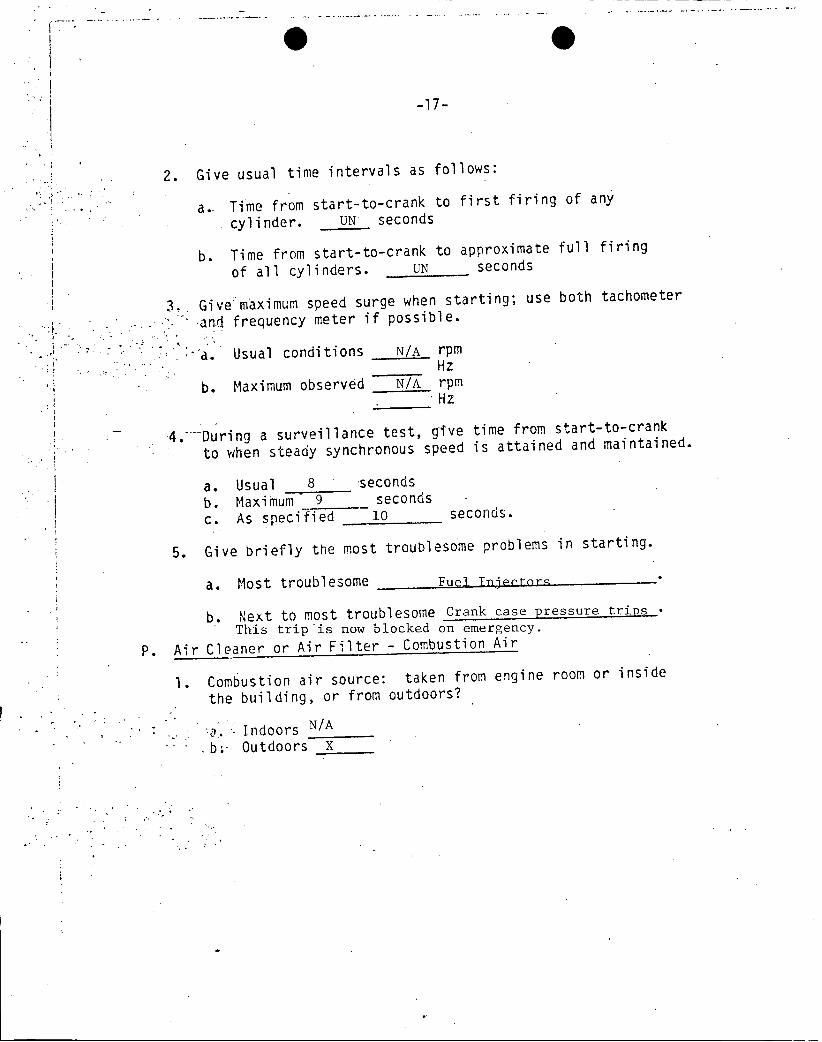
2. Give usual time intervals as follows:
a.. Time from start-to-crank to first firing of any
cylinder. UN seconds
b. Time from start-to-crank to approximate full firing of all cylinders. UN seconds
3. Give maximum speed surge when starting; use both tachometer
1and frequency meter if possible.
a. Usual conditions N/A rpm Hz
b. Maximum observed N/A rpm Hz
4- During a surveillance test, give time from start-to-crank
to when steady synchronous speed is attained and maintained.
a. Usual 8 seconds b. Maximum 9 seconds c. As specified 10 seconds.
5. Give briefly the most troublesome problems in starting.
a. Most troublesome Fuel Tnjctn-
b. Next to most troublesome Crank case pressure trips
This trip is now blocked on emergency.
P. Air Cleaner or Air Filter - Combustion Air
1. Combustion air source: taken from engine room or inside
the building, or from outdoors?
Indoors N/A
. Outdoors X

2. Give type and make of air cleaners or air filters:
a. Oil bath N/A Make N/A
b. Oil wetted screen N/A Make N/A
c. Paper N/A Make N/A
d. Other Fiber Make mirgeoc Mnning
e. Precleaner: Yes No x
3. Excessive air flow restriction and servicing need determined by?
a. Instrument such as:
manometer No
If other give type N/A b. Personal judgement by appearance, etc. Yes c. By smoking exhaust No d. Time schedule No e. Other (Specify) N/A
4. Are climatic extremes normally experienced such as:
a. Air heavily loaded with water mist, high humidity and low temperature? Yes No x
b. Blowing sand and dust? Yes No x
c. Blowing snow (blizzards)? Yes No X d. Other-Name N/A
5. Are climatic extremes potentially possible such as:
a.. Air heavily loaded with water mist, high humidity and low temperature? Yes X No'
b. Blowing sand and dust? YesTx No ___
c. Blowing snow (blizzards)? Yes X No d. Other-Name N/A
Q. Temperature Conditions
1. Ambient outside hottest 104 OF.
2. Ambient outside coldest 10 OF.
3. Engine-generator room hottest 105 *F.
4. Engine-generator room coldest 55 OF.
5. Inside switch gear hottest 105 0 F

. 19
R. Operator Qualifications (as presently exists, and suggested minimums if different)
1. Minimum education required (check)
Existing Sugested
a. High School . X x
b. Trade School
c. Technical School _
*. No minimum
2. Minimum Years of operating experience (diesel electric generator)
Existing Suggested
a. 0-3 x x b. 3-6 _
c. 6-10 _
d. 10-15
3. Operator training
Existing Suggested
a. Military
b. Industrial
c. On-the-job X X d. Combination of a, b,
and c (indicate which)
4. Lcensing required
Existina Suggested
a. State
b. Federal X X d. Utility or self
. None _

-20
S. Are any foreign gases such as propane, freon, halon, carbon dioxide, etc. stored in the: Diesel Engine room? Yes No x or adjacent buildings? Yes X No
If yes, (other than hand portable fire extinguishers), then identify gases and give approximate tank size.
-3Gases CO2 -Vomef(ft+ 1525 lbs.
T. Does control system automatically bypass, in emergency starting, any engine temporarily out of service for maintenance? Yes No X
If yes, then how many failures to bypass have occured? NIA
U. Does the control system automatically override the test mode under emergency conditions? Yes x No
V. Have repetitive mechanical failures occurred in any component part or subsystem of the engine, generator, or switch gear, etc.? Yes X No
If yes, then which part or subsystem? Fuel Injectors
How many failures? 4
Give nature of failure. Sticking Injectors
W. Would periodic (yearly or other) evaluation and/or testing by "outside experts" contribute significantly to the dieselgenerator reliability? Yes X No
Give brief reasons for the answer. Manufacturer should check units on refueling outages normally
and anytime their expertise is needed.

-21
X. 1. Give the accumulated time-load operating record for each diesel-generator unit from installation to the present (Running Hours): A - 499.8 Hours
B - 494.9 Hours
Preoperational test Date 5-5-70
Engine : Surv. Testing & : Emergency Total :Serial No. Maintenance Hrs. : and Other Hours
No Load : Loaded : Service Hrs.
A 38D86803OTDSM12: UN : UN UN : 499.8
B 38D868025TDSM12 UN UN : UN 494.9
2. Surveillance test load (percent of continuous rating) 100%
3. Give the projected or planned time-load operation for each diesel-generator unit during the next 12 months.
:Surveillance & : Emergency : Total :Maintenance Hrs. : and other : Hours
: ,Service Hrs. :
70 0 . 70
4. Provide the following summary of the periodic surveillance testing experience:
a. Starting date of surveillance testing (OL date) 9-1-70 b. Periodic test interval Bi-Weekly-Refueling c. Total number of surveillance tests performed 202 d. Total number of test failures 6
failure to start 1 failure to accept load None failure to carry load 5 failures due to operator error _ failure due to equipment not being operative during emergency conditions None
e.. Supply a copy of the surveillance test procedures with this completed questionnaire. PT-23.1
PT-23.2 - Attached
PT-23.3

-22
Additional Comments
Y. General Suggestions
Briefly give constructive criticism or suggestions as to
improvement in reliability of the diesel generators. These remarks may cover tests, maintenance, practices, orders, policy, adjustments, etc.

H. OBINSON STEAM ELECTIfC PLANT
UNIT NO.2.
PERIODIC TEST NO. CPL-PT-23.1
EMERGENCY DIESELS
BI-WEEKLY INTERVAL
REVISION 4
OCTOBER, 1977
TEST PROCEDURE APPROVAL
RECOMMEND / APPROVAL: ,;
Operating Suervisor Date
APPROVED:__
Plant Manager / Date

H1. B. ROBINSON STEAM ELECTRIC PLANT PT-23.l:1
UNIT NO. 2
PERIODIC TEST NO. CPL-PT-23.1
EMERCENCY DIESELS
BI-WEEKLY INTERVAL
REVISION 4
OCTOBER, 1977
1.0 PURPOSE
1.1 To verify mechanical performance and assess operational readiness
of components to fulfill their required safeguard functions.
1.2 The valves shall be tested in accordance with ASME Section XI "Rules
for Inservice Inspection of Nuclear Power Plant Components", editions
or addenda as set forth in Technical Specifications; and to comply
with the testing requirements set forth in Technical Specifications.
2.0 SCOPE
2.1 To ensure that the diesel generators will operate properly when
required during emergency conditions.
2.2 The following test quantities shall be measured or observed as
applicable:
2.2.1 Valves
1. Valve stem travel or disk movement
2. Proper operation of Remote Position Indicators (R.P.I.'s)
3. Time required to cycle valve
4. Verification that the valve assumes its proper failure
position on loss of operating power.
2.3 All data will be compared to baseline data after the completion of
this .test.

PT-23.1 :2
3.0 REFERENCES
3.1 Technical Specification 4.6.1.1; 4.6.2; 4.6.3.3
3.2 ASME Section XI, Subsection IWV
3.3 CPL-OP-07
3.4 Engineering flow diagrams:
3.4.1 Emergency Diesel Generator Systems
G-190204
3.4.2 Service and Cooling Water Systems
G-190199
4.0 EQUIPMENIT REQUIRED
4.1 Stopwatch
5.0 PRECAUTIONS AND LIMITATIONS
5.1 Only one diesel generator shall be tested at a time.
5.2 A minimum fuel oil storage of 25,000 gallons.
NOTE: 19,000 gallons in diesel fuel oil tank plus 6,000 gallons in
I.C. turbine oil tank or 25,000 gallons in diesel fuel oil
tank.
6.0 PREREQUISITES
6.1 The diesel generators are aligned for operation in accordance with
CPL-OP-07.
6.2 The plant is in such a condition that performing this test will not
prevent the system from performing its intended safety function.
There are no outstanding OWP's which could adversely affect this
system.

PT-23.1:3
6.3 Any steps that are not applicable shall be marked N/A.
6.4 Unless otherwise noted, the data recorded in this PT is "as found".
If adjustments are performed, the "as left" data will be recorded
adjacent to the "as found" and remarks made as appropriate.
6.5 The Shift Foreman has given permission to perform this test and all
prerequisites are met.
Authorizing Shift Foreman Date.
7.0 DIESEL GENERATOR TEST
7.1 Initial Conditions
7.1.1 480V breakers lined up and in normal service
7.1.2 Emergency diesel generator "A" and "B" in emergency standby
condition and system aligned per CPL-OP-07.
7.1.3 Air start solenoid defeat switch to normal position ("A" and
"B" diesels).
7.1.4 All emergency diesel generator annunciators cleared.
7.1.5 Verify emergency diesel generator "Trips Defeat" key switches
are in the "Trip Defeat" position.
7.1.6 Station an auxiliary operator in the respective diesel gener
ator room to monitor the starting of the diesel generator and
to observe and time the opening and closing of service water
valves TCV-1660.and TCV-1661.

PT-23.l:4
7.2 Diesel Generator "2A" Test Procedure
7.2.1 Ensure that field voltage control switch is in the "auto" position.
7.2.2 "Parallel-Isolation" switch to parallel.
7.2.3 Observe, time and record the opening of TCV-1660 on the attached
data sheet when the diesel starts.
7.2.4 Diesel "2A" controls in remote start position.
7.2.5 Turn 2A diesel generator switch (on RTB) to START position. (2A'diesel
generator will prelube two minutes, start and come up to speed.
7.2.6 After the diesel has run for one minute, reinstate the diesel
engine trips by placing the Engine Trips Defeat Key Switch in the
"Trips in Service" position.
NOTE: Monitor the diesel engine control panel closely during this
one minute time period. If any abnormal conditions are
indicated, manually trip the diesel generator.
7.2.7 Flash field and adjust Generator "2A" terminal voltage as required
for load operation.
7.2.8 Synchronize Generator "2A" with Bus E-1.
7.2.9 Close Breaker 52/17B and adjust governor to assume rated.
load of 2500 kw for one hour. Complete attached data sheet.
Time Closed_
7.2.10 Reduce Generator "2A" load. Time Reduced
7.2.11 Observe the closing of TCV-1660 and record on the attached data
sheet when the diesel stops.
7.2.12 Open Breaker 52/17B and shutdown diesel "'2A".
7.2.13 Diesel "2A" controls in remote start position.
7.2.14 "Parallel-Isolation" switch to isolation.

PT-23.1 :5
7.2.15 Place the engine "Trips Defeat" key switch in the "Trip Defeat"
position and remove the key.
.7.3 Diesel Generator "2B" Test Procedure
7.3.1 Ensure that field voltage control switch is in the "auto" position.
7.3.2 "Parallel-Isolation" switch to parallel.
7.3.3 . Observe, time and record the opening of TCV-1661 on the attached
data sheet when the diesel starts.
7.3.4 Diesel "2B" controls in remote start position.
7.3.5--Turn 2B diesel generator switch (on RTB) to START position.
(2B diesel generator will prelube two minutes and come up to
speed).
7.3.6 After the diesel has run for one minute, reinstate the diesel
engine trips by placing the Engine Trips Defeat Key Switch in
the "Trips in Service" position.
NOTE: Monitor the diesel engine control panel closely during
this one minute time period. If any abnormal conditions
are indicated, manually trip the diesel generator.
7.3.7 Flash field and adjust Generator "2B" terminal voltage as required
for load operation.
7.3.8 Synchronize Generator "2B" with Bus E-2. .
7.3.9 Close breaker 52/17B and adjust governor to assume rated load of
2500 kw for one hour. . Time Closed
7.3.10 Reduce Generator "2B" load. Time Reduced
7.3.11 Observe the closing of TCV-1661 and record on the attached data
sheet when the diesel stops.

PT-23.1:6
7.3.12 Open Breaker 52/27B and shutdown diesel "2B". .
7.3.13 Diesel "2B" controls in remote start postion
7.3.14 "Parallel-Isolation" switch to isolation
7.3.15 Place the Engine Trips Defeat Key Switch in the "Trip Defeat"
position and remove the key.
8.0 Diesel Generator Valve Test
8.1 The necessary valve stem or disk movement shall be established by
exercising the valve and verifying travel by the method(s) indicated
on the valve data sheet.
- 8.2; Perform all required tests as indicated byblank data blocks on the
appropriate valve data sheet(s).
9.0 COMPLETION OF TEST
9.1 All required tests have been completed, all required data has been
recorded and the system has been restored to pretest condition.
10.0 VALVE ACCEPTANCE CRITERIA
10.1. Each valve shall exhibit the required change of valve stem or disk
position by full stroke, part stroke, and/or fail testing. For
valves required to be stroke-timed, the valve shall stroke within
time indicated on the valve data sheet. Any abnormalities or erratic
action shall be reported.
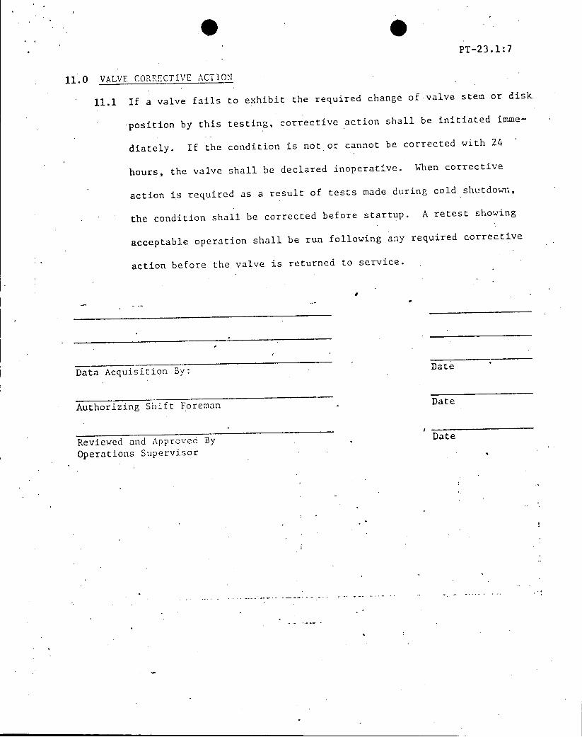
PT-23.1:7
11.0 VALVE CORRECTIVE ACTION
11.1 If a valve fails to exhibit the required change of valve stem or disk
position by this testing, corrective action shall be initiated imme
diately. If the condition is not or cannot be corrected with 24
hours, the valve shall be declared inoperative. When corrective
action is required as a result of tests made during cold shutdown,
the condition shall be corrected before startup. A retest showing
acceptable operation shall be run following any required corrective
action before the valve is returned to service.
Data Acquisition By: Date
Authorizing Shift Foreman Date
Reviewed and Approved By Date
Operations Supervisor

PT-23.1:8
ENGINE DATA SHEET
Diesel fax. Trip _____ ____or
or Point Min.*
A B
Lube oil pressure, psig 2.0 min 18
L.O. strainer inlet pressure, psig
L.O. strainer outlet pressure, psig
L.O. strainer AP, psi . 15 max.
L.O. filter inlet pressure, psig
L.O. filter outlet pressure, psig
L.O. filter AP, psi 13 max.
Coolant discharge pressure, psig 20 min. 12
Coolant temperature, o 195 max. 205
0.8 +0.5
Crankcase vacuum, inches water (vacuum) (press.)
* Write a trouble ticket if the maxumum or minimum is reached and so
state below:

VALVE DATA SHEET
VERIFICATION OF STROKE TIME
TRAVEL BY (SEC.) ACCEPTANCE C4L C4 0 1
) W P &N. HI CRITERIA
STEM LIGHTS OTHER OPEN CLOSE U P-4
T660 C N/A 'A/ N/A N_/_A 60 Seconds TC6 C N- /
1I__ C /A N/A N N/A /A N/A 60 Seconds
All spaces next to valve number shall be filled in with an appropriate entry, initials or N/A as applicable.
* List in comments the method used to determine valve travel.
C0?IENTS:*
Date: __ Performed By:
Date: Reviewed By:

H. B. ROBINSON STEAM ELECTRIC PLANT
UNIT NO. 2
PERIODIC TEST CPL-PT-23.2
REVISION 3
SEPTEMBER 30, 1975
EMERGENCY DIESEL AUTO START ON LOSS OF POWER AND SAFETY INJECTION
EMERGENCY DIESEL TRIPS DEFEAT
REFUELING INTERVAL
TEST PROCEDURE APPROVAL
RECOMMEN D APPROVAL: EngiDATE:
Engineeri g Supervisor
APPROVED: /___DATE:
an t tf1agor

H. B. ROBINSON STEAM ELECTRIC PLANT
UNIT NO. 2
PERIODIC TEST NO. CPL-PT-23.2
SEPTEMBER 30, 1975
EMERGENCY DIESEL AUTO START ON LOSS OF POWER AND SAFETY INJECTION
EMERGENCY DIESEL TRIPS DEFEAT
REFUELING INTERVAL
REV.3
1.0 PURPOSE
1.1 The purpose of this test is to:
1.1.1 Assure auto start of the-diesel generators, load shedding
and restoration to operation of particular vital equipment
initiated by a loss of power to the vital busses together
with a Safety Injection signal.
1.1.2 Assure that the diesel generators will start and assume
required load within 50 seconds after the initial starting
signal.
1.1.3 Demonstrate that the diesel protective trip devices will
not trip the diesels when in the "trips defeat" position.
1.2 Satisfactory completion of this test will fulfill the require
ments of Technical Specifications 4.6.1.2 and 3.7.1 D.
2.0 EQUIPMENT LIST
2.1 20 point event recorder Rec. Calib. Date . Ser. No.
2.2 Stop watch

Vage 2
3.0 INITIAL CONDITIO*
3.1 Connect the recorder as shown below:
EQUIPMENT RELAY RACK CONTACT RECORDER SAFEGUARD SHEET
RHR Pump A 2RHRA 51 12 SI Pump A 2SIA 51 4 6 2 - 12
HVH-1 2HVIl 51 4 6 3 12
HVH-2 2HVH2 51 4 6 4 12
SW Pump A . 2SWA 51 4 6 5 12
SW Pump B 2SWB 51 4 6 6 12
870A, 841A 867A, 744A SIlix 52 12 16 7 6 870B, 841B 867B, 744B J S121X 64 12 16 8 6
RHR Pump B 2RHRB 63 4 6 9 12
SI PumpC -- 2SIC 63 4 6 10 12
HVH-3 2HVH3 63 4 6 11 .12
HVH-4 2HivHi4 63 4 6 12 12
SW Pump C 2SwC 63 4 -6 013 12
SW Pump D 2SWD . 63 4 6 14 12
SWBP-A Relay G(83X) Aux. Pnl. 9 10 15 CWD 845 FB
SWBP-B Relay G(83X) Aux. Pnl. JB 10 16 . CWD 846
SI Pump B * . Aux. Pnl. ---
JE 12 114 1 7 0- CWD 238
AFW Pump A * Aux. Pnl. .FF . 6 -8 O18 CWD 651
AFW Pump B * Aux. Pnl. JE H~-i---019 CD655 JF
Push Button for Time Zero -o20 -
120 VAC L from computer
L
* Connect an auxiliary relay in series with the "b" contacts of the subject breaker to obtain a spare contact. Numbers denote connection points on the auxiliary panel.

3.0 INITIAL CONDITIONS W tinued)
3.2 Plant in a cold or refueling shutdown condition on RHR
3.3 Refueling water storage tank above the low level alarm point.
3.4 All control rods on bottom.
3.5 SI Accumulators A, B, and C .are depressurized to less than RCS
pressure.
3.6 Emergency diesel generators in standby condition.
3.7 RHR Pumps "A" and/or "B" running as required for RCS temperature
control.
3.8 Service water system lined up for normal service.
3.9 Perform the following valve line up:
3.9.1 SI Pump Recirculation
888A SI Pump A Discharge Closed
856A Recirc. to RWST Open
888B SI Pump B Discharge Closed
856B Recirc. to RWST Open
888C SI Pump C Discharge Closed
886A SI Pump A Suction Open
886B SI Pump B Suction Open
886C SI Pump C Suction Open
805B SFP to RWST Closed
864A Refueling Tank Isolation Open
864B Refueling Tank Isolation Open
895P SI Test Line to RWST .Isolation Closed
898G SI Pump A Miniflow Isol-ition Open
89811 SI Pump B Miniflow Open
898J SI Pump C Miniflow Isolation Open

L '4
3 .0 INITIAL CONDITIONS # tinued)
865A "A" Accumulator Isolation Closed
865B "B" Accumulator Isolation Closed
865C "C" Accumulator Isolation Closed
866A Hot Leg Injection Closed
866B Hot Leg Injection Closed
841A Boron Injection Tank to Boric Acid Tanks Closed
841B Boron Injection Tank to Boric Acid Tanks Closed
8 6 7A Safety Injection Line to Boron Injection
Tank Closed
867B Safety Injection Line to Boron Injection
Tank Closed
870A Safety Injection Line to Cold Legs Closed
870B Safety Injection Line to Cold Legs Closed
3.9.2 RR Recirculation
862A Refueling Water to PJR Pump Suction Closed
862B Refueling Water to RHR Pump Suction Closed
752A RHR Pump A Suction Open
752B RHR Pump B Suction Open
75 4A RHR Pump A Discharge Open
754B RRR Pump B Discharge Open
757C RHR Hx A Bypass Open
757D RHR Hx B Bypass Open
757A RHR Hx A inlet Open
757B RHR Hx B Inlet Open
759A RHR Hx A Outlet Open/Closed
759B RH R Hx B Outlet Open/Closed
750 Loop 2 Hot Leg to RHR Open
751 Loop 2 Hot Leg to RH1R Open
Page>
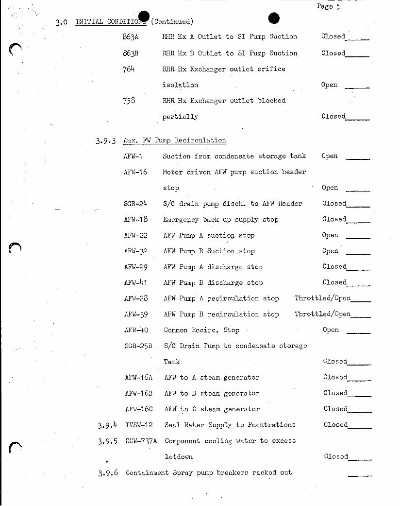
3.0 INITIAL CONDITIO (Continued)
B63A RHR Hx A Outlet to SI Pump Suction Closed
86M RR Hx B Outlet to SI Pump Suction Closed
764 RHR Hx Exchanger outlet orifice
isolation Open
758 RHR Hx Exchanger outlet blocked
partially 'Closed
3.9.3 Aux. FW Pump Recirculation
AFW-1 Suction from condensate storage tank Open
AFW-16 Motor driven AFW pump suction header
stop Open
SGB-24 S/G drain pump disch. to AFT Header Closed
AFW-18 Emergency back up supply stop Closed
AFW-22 AFW Pump A suction stop Open
AFW-32 AFW Pump B Suction.stop Open
AFW-29 AFW Pump A discharge stop Closed
AFW-141 AFW Pump B discharge stop Closed
AFW-28 AFW Pump A recirculation stop Throttled/Open
AFW-39 AFW Pump B recirculation stop Throttled/Open
AFW-4o Common Recirc. Stop Open
SGB-25B S/G Drain Pump to condensate storage
Tank Closed
AFW-16A AFV to A steam generator Closed
ATW-16B AFJW to B steam generator Closed
AFW-16C AFW to C steam generator Closed_
3.9.lt IVSW-12 Seal Water Supply to Pnentrations Closed_
3.9.5 CCW-737A Component cooling water to excess
letdown Closed
3.9.6 Containment Spray pump breakers racked out
3.0 INITIAL CONDITI (Continued) t
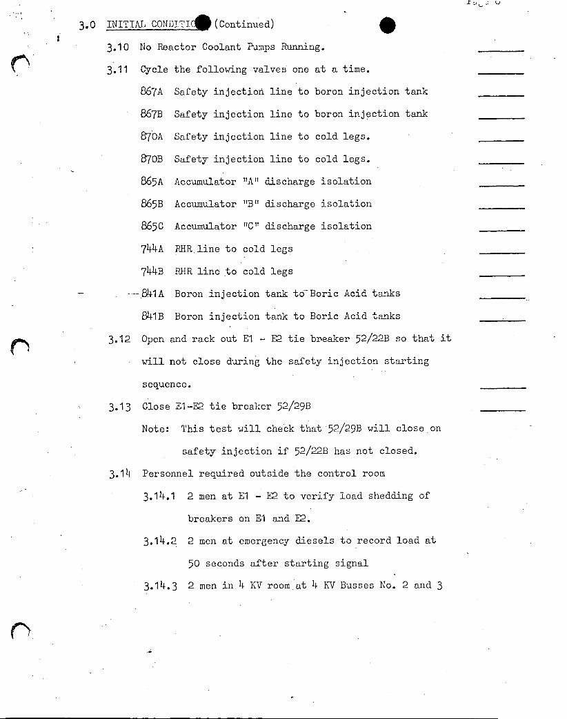
3.10 No Reactor Coolant Pumps Running.
3.11 Cycle the following valves one at a time.
867A Safety injection line to boron injection tank
867B Safety injection line to boron injection tank
870A Safety injection line to cold legs.
870B Safety injection line to cold legs.
865A Accumulator "A" discharge isolation
865B Accumulator "B" discharge isolation
865C Accumulator "C" discharge isolation
744A RHR.line to cold legs
74kB RHR line to cold legs
--.841A Boron injection tank td"Boric Acid tanks
841B Boron injection tank to Boric Acid tanks
3.12 Open and rack out El - E2 tie breaker 52/22B so that it
will not close during the safety injection starting
sequence.
3.13 Close El-E2 tie breaker 52/29B
Note: This test will check that 52/29B will close on
safety injection if 52/22B has not closed.
3.14 Personnel required outside the control room
3.14.1 2 men at El - E2 to verify load shedding of
breakers on El and E2.
3.14.2 2 men at emergency diesels to record load at
50 seconds after starting signal
3.14.3 2 men in 4 KV room.at 4 KV Busses No. 2 and 3

4.0 PRECAUTIONS
4.1 During this test power will be lost to 48O V Busses No. 1 and 3
4.2 During this test power will be momentarily lost to 480 V Emergency
Busses E-1 and E-2.
4.3 The safety injection pumps are lined up to recirculate with their
manual discharge valves closed and will not inject water into the
RCS during this test. These pumps should not be run on recircu
lation for more than 15 minutes.
4.4 The auxiliary feedwater pumps are lined up to recirculate with
their manual discharge valves closed and will not inject water
into the steam generators during this test. These pumps should
not be run on recirculation for more than 15 minutes.
4.5 The Residual Heat Removal (RHR) pumps will be lined up to recircu
late the RCS through 750 and 751 and the normal RHR flow path
during this test.
4.6 Do not prelube the diesel generators and then not start them.
4.7 Ensure that refueling operations are not in progress.
4.8 Instrument air will be lost to containment during the Safety Injec
tion portion of this test.
4.9 Do not exceed 3750 gpm flow rate with one RKR pump running and 7500
gpm flow rate with 2 RHR pumps.
4.10 Halt any steam generator tests or operations requiring work in or
around the channel head.
4.11 The station batteries should be capable of accepting emergency loads.
4.12 Both diesel field flashing batteries charged and operable.

Page 8
5.0 INSTRUCTIONS
NOTE: The following Steps 5.1, 5.2, 5.3, 5.4, 5.5, 5.6, 5.7 and
5.8 are to be performed after all other requirements for this
test are met and just prior to the initiation of the start of
the test.
5.1 To simulate an undervoltage on El such that breaker 52/29B will
close, Jumper Points 11 and 12 on Terminal Block 5L in safeguards
rack 51, and Points 3 and 12 on Aux. Panel JA.
5.2 Open 841 A & B Boron Injection Tank to.Boric Acid Tanks _
5.3 If the turbine is on the turning gear, start the emergency
D.C. lube oil pump.
5.4 If the seal oil system is in operation, start the D.C. air
side seal oil backup pump and leave the A.C. air side seal
oil pump running.
5.5 Stop the RHR pump (s)
5.6 Close 744A RHR to cold legs. Closed
Close 744B RHR to cold legs. Closed
5.7 Prelube both 2A and 2B diesels for 1 minute 2A
2B
5.8 Verify one component cooling water pump on the vital
bus (B or C) operating
5.9 Announce over the plant P.A. System:
"A5-cecond count down follows for loss of power and safety injection"
(Twice) 5
3
2
1
Zero

5.0 INSTRUCTIONS (CONTtD) P
5.10 Perform the following steps simutaneously to initiate a safety
injection signal together with a loss of power.
5.10.1 At 4 KV Bux No. 2
Open breaker 52/13. 4KV Bus No. 2 supply to
station service transformer 2A
5.10.2 At 4 KV Bux No. 3
Open breaker 52/15 4 KV Bux No.3 supply to
station service transformer 2C
5.10.3 Depress either safety injection push button to initiate
a safety injection signal.
5.10.4 Note this time as .time 0. (Start the stop watch)
Mark the 20 point event recorder at time "0".
5.11 Load shedding.
5.11.1 Verify that the following breakers trip open
52/1B 48OV Bus No. 1 and El feeder breaker
52/2B 48ov Bus No. 1 feeder breaker
52/18B El main breaker
52/29B El - E2 tie breaker
52/16D 48OV Bus No. 3 and E2 feeder breaker
52/15B 48OV Bus No. 3 main breaker
52/28 E2 main breaker
Note exceptions
5.11.2 Verify load shedding of all breakers on El except for
MCC-5.
Note exceptions

Page 10
5.0 INSTRUCTIONS (Co ninued)
5.11.3 Verify load shedding of all breakers on E-2 except for
MCC-6.
Note exceptions
5.12 Restoration of Power to Vital Busses by the Emergency Diesels
5.12.1 Verify that emergency diesels start. 2A
2B
5.12.2 Verify that emergency diesel breakers close.
2A diesel 52/17B Closed
2B Diesel 52/27B Closed
5.12.3 Verify that El - E2 tie breaker closes.
52/29B Closed
Note: 52/29B should close because an undervoltage condition
on Bus El is simulated along with SI signal..
5.13 Verify.that the following pumps and fans start.
Note: The time indicates time after 52/17B and 52/27B closed.
This PT does not include timing the start of each pump.
SI Pump A 5 sec.
SI Pump c 5 sec.
SI Pump B 10 sec.
RHR Pump A 15 sec.
RIR Pump B 15 sec.
SW Pump A 20 sec.
SW Booster Pump A 20 sec.
SW Pump C 20 sec.
SW Booster Pump B 20 sec.
SW Punip B 25 sec.
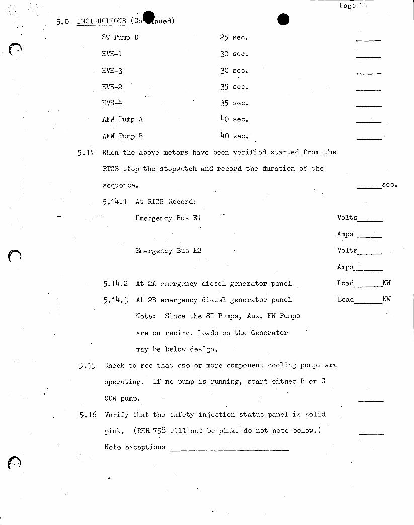
PaLJ 11
5.0 INSTRUCTIONS (Co nued)
SW Pump D 25 sec.
HVH-1 30 sec.
HVH-3 30 sec.
HVH-2 35 see.
HVH-4 35 sec.
AFW Pump A 40 sec.
AFW Pump B 40 sec.
5.14 When the above motors have been verified started from the
RTGB stop the stopwatch and record the duration of the
sequence. sec.
5.14.1 At RTGB Record:
Emergency Bus El Volts
Amps _
Emergency Bus E2 Volts
Amps
5.14.2 At 2A emergency diesel generator panel Load KW
5.14.3 At 2B emergency diesel generator panel Load KW
Note: Since the SI Pumps, Aux. Fn Pumps
are on recirc. loads on the Generator
may be below design.
5.15 Check to see that one or more component cooling pumps are
operating. If no pump is running, start either B or C
CUW pump.
5.16 Verify that the safety injection status panel is solid
pink. (RHR 758 will'not be pink, do not note below.)
Note exceptions .
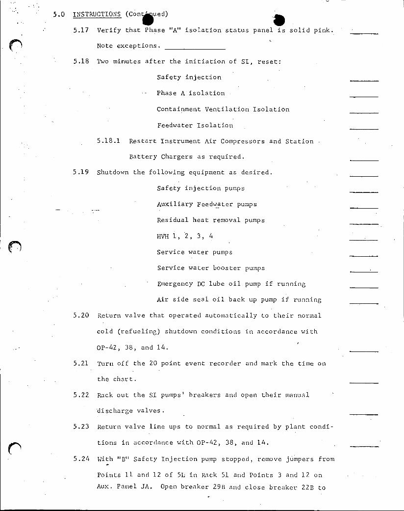
5.0 INSTRUCTIONS (Con ued)
5.17 Verify that Phase "A" isolation status panel is solid pink.
Note exceptions.
5.18 Two minutes after the initiation of SI, reset:
Safety injection _
Phase A isolation _
Containment Ventilation Isolation
Feedwater Isolation
5.18.1 Restart Instrument Air Compressors and Station
Battery Chargers as required.
5.19 Shutdown the following equipment as desired.
Safety injection pumps
Auxiliary Feedwater pumps
Residual heat removal pumps
HVH 1, 2, 3, 4
Service water pumps
Service water booster pumps
Emergency DC lube oil pump if running
Air side seal oil back up pump if running
5.20 Return valve that operated automatically to their normal
cold (refueling) shutdown conditions in accordance with
OP-42, 38, and 14.
5.21 Turn off the 20 point event recorder and mark the time on
the chart.
5.22 Rack out the SI pumps' breakers and open their manual
discharge valves.
5.23 Return valve line ups to normal as required by plant condi
tions in accordance with OP-42, 38, and 14.
5.24 With "B" Safety Injection pump stopped, remove jumpers from
Points 11 and 12 of 5L in Rack 51 and Points 3 and 12 on
Aux. Panel JA. Open breaker 29B and close breaker 22B to

5.0 INSTRUCTIONS (Co nued)
to complete the normal tie-bus line up.
5.25 Restore power to 48OV Bus No. 1
5.25.1 Close 52/44-i.KV Bus No. 2 supply to station
service transformer 2A.
5.25.2 Close 52/1B 480V Bus No. 1 and El feeder breaker.
5.25.3 Close breaker 52/2B 480V Bus No. 1 feeder breaker.
Note: Power is now restored to 480V Bus No. 1 from 4KV
Bus No. 2 but is still separated from El which is
being supplied from 2A diesel.
5.25.4 Synchronize Emergency Bus E-1 with system at 2A
diesel panel and close Breaker 52/18B, El main
breaker.
5.25.5 Separate 2A diesel generator from the system by re
ducing load to "O" and opening diesel generator breaker
52/17B 52/17B Open
5.25.6 Restore all normal loads to 480V Bus 1 and emer
gency Bus El.
5.26 Restore power to 48OV Bus No. 3
5.26.1 Close breaker 52/15 4KV Bus No. 3 supply to station
service transformer 2C.
5.26.2 Close breaker 52/16B 48Ov Bus No. 3 and E2 feeder
breaker.
5.26.3 Close breaker 52/15B 48oV Bus No. 3 feeder breaker.
Note: Power is now restored to 480V Bus No. 3 from 4KV
Bus No. 3 but is still separated from E-2 which is
being supplied from 2B.diesel.
5.26.4 Synchronize Emergency Bus E-2 with system at 2B
diesel panel and close breaker 52/28B, E-2 main breaker.

5.0 INSTRUCTIONS (Contoued)
5.26.5 Separate 2B diesel generator from the system by
reducing load to "0" and open diesel generator
breaker 52/27B.
5.27 Restore all normal loads to 480V Bus 3 and Emergency Bus E-2.
5.28 Diesel protective bypasses shall be demonstrated to be operable
by simulating a trip signal to each of the trip devices that is
bypassed and observing that diesel does not trip. Test the
trips for each diesel as follows:
5.28.1 Ensure 2A and 2B diesels trip defeat switches are 2A 2B
in the trips defeat position.
5.28.2 Low Lube Oil Pressure Trip
Isolate the lube oil pressure switch and gauge at
the 8 valve manifold. Bleed down low lube oil
pressure switch until red "low lube oil pressure
trip" light illuminates. The diesel should not
trip.
5.28.3 Place low lube oil pressure switch back in service.
5.28.4 Low Coolant Pressure Trip
Isolate the low coolant pressure switch at the 8
valve manifold. Bleed down the "low coolant
pressure" switch until the red "low coolant
pressure trip" light illuminates. The diesel
should not trip.
5.28.5 Place "Low Coolant Pressure" switch back in
service.

5.0 INSTRUICTIONS (Cout inued) 2A .2B
5.28.6 ' Clolnt Teri. Trp ..
Have I and C adjust temperature switch CTHS
until red "High Coolant Tenp _ri" light
illuminates. The diesel should not trip.
5.28. 7 Return temerature switch CIS to normal.
5.28.8 High Crankcase Pres;sure Triig
11ave I and C jumper pressure switch CP and
check that the "HILi Crankecse Pressure Tri2
light illuminiates. The diesel. should not
trip. _____ _____
5.28.9 Return pressure swi tch CP to normal
5.28.10 Startin Failure. Tri p of Fue]. Racks
Have. I aind C operate relay TD-2, assure red
'Starting Tailure trip" light illuminates.
The diesel should not trip.
5.28.11 Return relay )D---2 to normal,___

Page u
6.0 ACCEPTANCE CRITERIA:
This Periodic Test is acceptable if the requirements of Technical
Specifications 3.7.1.d and 4.6.1.2 are met.
APPLICABLE STEPS:
5.11, 5.12, 5.13 Diesel generators 2A and 2B must start automatically.
All breakers listed in Step 5.11 must load shed, and
all equipment listed in Step 5.13 must operate. The
diesels must assume required load within 50 seconds
after initial starting signal.
5.28 - Diesels shall not trip when initiating trip signals
In Step 5.28.
The reviewing authority may accept this test when the specific acceptance
criteria is not met if known plant conditions have caused an expected
variation in operation, provided no violation to Technical Specifications
or the FSAR occurs.
Date Completed: _
Performed By:
Reviewed by:
__Shift Foreman Date
Test Coordinator Date
Recommend Approval Date
Engineering Supervisor
Approved By Date Plant Manager

UN, T NO. 2
PER 1,01) 1C TEST CPL[-PT'-23. 3
SEPTEMBER i\ 30, 1976
DI1ESE L CJ,EERATO RS EMERC;ENCY F]IELD) VIUASHI1G
MNULI Cf,O)SURLE 0r E CN EATORS MANBREAREP'S
REIP'UI.KTAIG TNTIR\'AL
TESTI Pl-RO(UKDU El AT'PEOVAL
APPROVAl,: ' __
Rug inC,0rlill, oupelr\ i.sor Da
~1iIN ia ingt ,r Da ce L/

H. B. ROBINSON STEAM ELECTRIC PLANT
UNIT NO. 2
PERIODIC TEST NO. CPL-PT-23.3
SEPTEMBER 30, 1976
REVISION 3
DIESEL GENERATORS EMERGENCY FIELD FLASHING AND
MANUAL CLOSURE OF GENERATORS MAIN BREAKERS
REFUELING INTERVAL
1.0 PURPOSE
1.1 The intent of this Periodic jest is to verify both emergency busses
can be energized to provide vital safeguard equipment in the event
of total or partial loss of DC Power.
2.0 INITIAL CONDITIONS
2.1 Plant is at cold shutdown.
2.2 Diesel generators in standby condition.
2.3 Diesels have been shutdown for 24 hours.
NOTE: 24 hours ensures minimum effect of Residual Magnetism on Field Flashing.
3.0 PRECAUTIONS
3.1 This test is to be performed in a manner so that emergency
operation features of the system will not be decreased in
the event of an accident during the test.
3.2 Personnel involved in the P.T. should thoroughly familiarize
themselves with evolutions to be performed.
3.3 Notify shift foreman prior to performing this test.

Page 2
4.0 INSITRUCTIONS
4. 1 Diesel Generator 2A and Bus E-1
4.1.1 Announce the following over the.Plant P.A. System:
"Attention all personnel in Containment, disregard
the Hi-Flux at Shutdown Alarm until further notice '
4:1.2 Transfer all loads from 480V Bus E-1. to 480V
Bus E-2 except MCC-5.
4.1.3 Swap lnstrument .Bus No. 1 supply from WGG-5 to
MCC-8.
4.1.4 Transfer MCC-5 power supply from Bus E-1 to
480V Bus No. 3 as per OP-3, Plant Electrical
Distribution, Section F.
4.1.5 Open E-1/E-2 Tie Breaker 52/22B and pull breaker
control fuses.
4.1.6 Pull fuses on 2A Emergency Generator Main Breaker
52/17B and all equipment breakers that close when
voltage is lost and restored.
NOTE: Breakers that close on loss of voltage are
identified with a red DANGER plate.
4.1.7 Open 2A Emergency Generator Exciter.D-C supply
breaker on 125 VDC Panel A Circuit 8.
4.1.8 Open E-1 Main Breaker 52/18B.
NOTE: Emergency Diesel will start at this time.
4.1.9 Open E-1 Bus D-C Supply Breaker 'at 125VDC Panel
A Circuit 1.
4.1.10 Replace fuses in 2A Emergency Generu tor Main
Breaker 52/17B.
4.1.11 In Diesel Generator 2A Control Panel, position the
Field Flashing Switch to the Emergency Position.

PT-23.3 Con'd Page 3
4.0 INSTRUCT1ONS (Continued)
4.1.12 Establish operating voltage and frequency on Emergency
Generator 2A..
4.1.13 Manually close 2A Emergency Generator Breaker
52/17B by placing lover in manual closure device
on breaker and pushing downward.
4..1.14 NOTE: Bus E-1 will he energized at this time.
4.1.15 Close E-1 D--C Supply Breaker, Circuit 1 on
125VDC Panel A
4.1.16 Synchronize 2A Emergency Generator with 480V
system and close E-1 Main. Breaker 52/181.
4.1.17 Reduce load on 2A Emergency Generator, open
Generator Main Breaker And retire diesel.
4.1.19 Close 2A Emergency Generator Exciter D-C Supply
Breaker Circuit 8 on 125 VDC Panel A.
4.1.20 Place 2A Dicsel Generator Field Flashing Switch
in the normal position.
4.1.21 Return equipment to normal that starts on loss of
* voltage by holding the Start Switch on the RTGB
in the OFF position and replacing fuses.
NOTE: This completes the first portion of thie test.
4.2 Diesel Generator 2B and Bus E-2.
4.2.1 Transfer all loads from 480V Bus E-2 to Bus E-1
except MCC-6. .
4.2.2 Transfer all loads from MCC-6 and MCC-9 that can
be transferred to MCC-5 and MCC-10.
4.2.3 Swap Instrument Bus No. 4 from MCC-6 to MCC-B.

'T- 3. 3 Page
4.0 INSTRUCTIONS (Continued)
4.2.4 Pull fuses on 28 Emergency Generator Main Breaker
52/271B and all equipment breakers that close when
voltage has been lost and restored.
NOTE: Breakers that close on loss of voltage are
identified wti a red DANGER plate..
4.2.5 Open 28 Emergency Generator Exciteor D-C Supply
Breaker on 125 VDC Panel F CircuiLt 8.
4.2.6 Announce on P .A. System, "Attention all personnel,
some pla n t lighting wil1 be lost momentari.
4.2.7 Open Bus E-2 Main Breaker 52/281,.
NOTE: 213 Emergency Dicsel wi11 start at this time, and power will be. lost to MCC-6 and MCC-9.
4.2.8 Open Bus, E-2 125VDC Supply Breaker on 125VDC
Panel B Circuit 1.
4.2.9 Replace fuses in 21. Emcrgency Genera tor Main
Breaker 52/2713.
4.2.10 In Diesel Generator 28 Control Panel, position
the Field Flashing Switch to the Emergency
position.
4 .2. 11 Establish operating voltage. and frequency on 28
Emergency Generator.
4.2. 12 Manually close 2B Emergency Generator Breaker by
placing lever in manual closure device on breaker
and pushing downward.
NOTE: Bus E-2, MCC-6, and NCC--9 will be energized
at this time . Be sure "I)" Battery Charger
has inergized.
4. 2.13 Close Bus E-1 D-C Supply Breaker Circuit I on
125 VDC Panel B.
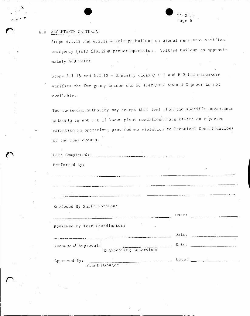
PT-23. 3 Page 6
6.0 ACCEPTANCE CRIlTERIA:
Steps 4.1.12 and 4.2.11 - Voltage buildup on diesel generator verifies
emergency field flashing proper operation. Voltage buildup to apprOXi
mately 480 volts.
Steps 4.1.15 and 4.2.12 - Manually closing E-1 and E-2 flain reakers
verifies the Emergency Busses can be energized when.D-C power is not
avai lab l.
The reviewing autho r ity may accept thi s Lest when the spec i fic acceptance
criteria is not I-,t if knowin plaint cond itions have caused an e >:pected
variation in operation, provided no violation to Technical Specifications
or the FSAR occurs.
Date Completed:
Performed By:
Reviewed By Shift Foreman:
Date:
Reviewed by Test Coordinator:
Date:
Recommend App rova.: Date:
Engineer ing Supcrvisor
Approved By: __Date:
Plant Manager


![PRO 810580 06 Condensate-Manual en[1]](https://img.pdfslide.us/doc/110x75/553317b04a7959824c8b47e3/pro-810580-06-condensate-manual-en1.jpg)