Embed Size (px)
Citation preview
1
REGULATIONS FOR DESIGN, CONSTRUCTION AND REPAIR OF INDIVIDUAL SEWAGE DISPOSAL SYSTEMS
PURSUANT TO MARIN COUNTY CODE CHAPTER 18.06 Adopted: May 6, 2008
Corrected: Jan. 13, 2016 100 PERMIT APPLICATION AND PROCEDURES 101 Application for an Individual Sewage Disposal Permit shall be made on a form supplied by the Health
Officer accompanied by the appropriate fee. 102 All information required on the form must be supplied or the application will be deemed incomplete and
returned to the applicant. 103 Three copies of a detailed Plot Plan shall accompany each application for a permit, drawn to scale of not
less than 1 inch equals 20 feet. Plans shall be a minimum of 8 1/2" x 11" in size and not greater than 24" x 36" in size. Plans shall contain the following:
A. Location map indicating location of parcel with respect to community and nearest public road. B. Parcel boundary and dimensions. C. Owner's name and address of dwelling or structure, Assessor's Parcel Number, north arrow and plan scale. D. Location of all wells (both on site and in general vicinity), springs, watercourses and water bodies, marsh areas, drainage ditches, channels, cuts, embankments, natural bluffs or unstable land forms on the property or within 100 feet of any portion of the proposed system or reserve area. E. Location of existing and/or proposed structures, swimming pools, retaining walls, driveways, paved
areas, water lines, underground utilities, storage tanks (underground and above ground), all trees greater than or equal to six (6) inch dbh and easements on the site and within 25 feet of the proposed
system. F. Contours, and/or spot elevations, except those parcels where the average slope is 5% or less may indicate only the direction and percentage of slope. The direction and percentage of slope of the drainfield area shall be shown for all plans. G. Location of any existing sewage disposal system(s) on the property. H. Layout (including dimensions) of proposed system. I. Typical trench section and any other essential construction details, such as pumps, intercept drains,
supplemental treatment units, etc. J. Location of individual soil percolation test holes and soil profile holes. K. Name and signature of the Registered Civil Engineer, Registered Environmental Health Specialist,
Certified Engineering Geologist, Registered Geologist, or Certified Professional Soil Scientist responsible for design.
104 Soil percolation test results, soil profile logs and/or results of soil textural analysis shall accompany each
application, on forms supplied or approved by the Health Officer. 105 Each application shall be accompanied by the calculations used to determine sizing of the septic tank and
absorption area and any other special design features.
2
106 Acceptance of an application for a permit as complete does not guarantee that a permit will be issued. Issuance of a permit does not ensure that a system will operate satisfactorily.
107 Upon issuance of a septic system permit and building permit (if applicable), work may commence on
construction of the approved system. The septic tank and drainfield/absorption area may not be covered until an inspection is performed by the Health Officer. A minimum of two business days advance notice is required to arrange for final inspections by the Health Officer.
108 A copy of the building plans, including the approved sewage disposal system, shall be available at the job
site during the system installation and until the system is approved by the Health Officer. 200 DEFINITIONS 201 Absorption Area: The effective absorption area shall include only the two sidewall areas below the bottom
of the drainfield pipe. 202 Alternative System: Any individual onsite treatment system that includes a supplemental treatment unit in
addition to or in place of a standard septic tank and/or does not include standard leaching trenches for effluent disposal. See additional information provided in Section 800 (separate package)
203 Bedrock: Solid rock, which may have fractures, that lies beneath soils and other unconsolidated material.
Bedrock may be exposed at the surface or have an overburden up to several hundred feet thick. 204 Bedroom: Any room designated by applicant as a "bedroom" or providing privacy, such as sewing rooms,
dens, offices, studios, lofts, game rooms, etc., may also be considered as bedrooms. Rooms having one or more of the following features may not be considered by the Health Officer to constitute a bedroom:
A. A large, arched doorway without a door which opens onto the entryway or a main activity area.
B. Use of a half wall or railing along at least one side of the room. Notwithstanding the above provisions, the minimum number of bedrooms for any dwelling shall be no less
than the following:
Gross Floor Area No. of Bedrooms
0-1450 S.F. 1
1451-2000 S.F. 2
2001-2900 S.F. 3
Over 2900 S.F. 4
205 Building: A structure including decks and steps, whether covered or uncovered, breezeways, covered
patios, carports and similar structures. 206 Clay: As a soil separate, the mineral soil particles less than 0.002 millimeters in diameter. As a soil textural
class, soil material that is 40 percent or more clay, less than 45 percent sand, and less than 40 percent silt. 207 Conventional (Standard) System: Sewage from the structure flows by gravity into a septic tank. Effluent
is then discharged to the soil via gravity or mechanized delivery (pumps or dosing siphons). 208 Cut or Embankment: Any altered area of land surface having a distinctly greater slope than the adjacent
natural ground surface, over 24 inches in vertical height, and any part of which is lower in elevation than the ground surface at the nearest point of the individual sewage disposal system. Cuts supported by retaining walls or similar structures shall be included within this definition.
3
209 Disinfection: The destruction of disease-causing organisms (e.g. bacteria, viruses) by the application of
chemical or physical agents. 210 Dosing Tanks/Sump Chamber/Recirculating Chamber : A watertight covered receptacle made of
approved materials, designed to collect treated sewage for a period of time and then periodically discharge it into an absorption area or supplemental treatment unit by means of an automatic siphon or pump so that the effluent is distributed as designed.
211 Downslope Property Line: A property line of the subject property where the ground on the adjacent
property slopes downward from that property line. 212 Drainfield: System of aggregate-filled trenches, gravelless chamber systems, drip systems, or bed(s) that
distributes treated sewage effluent for absorption into the soil (also "Leachfield", "Soil Absorption System"). 213 Drip Dispersal: A method of underground wastewater dispersal capable of delivering small precise
volumes of wastewater effluent to the infiltration surface through flexible polyethylene tubing with in-line emitters.
214 Dual Drainfield: An effluent disposal system consisting of two complete drainfields typically connected by
an accessible diversion valve and intended for alternating use on a periodic basis. 215 Effective Trench Depth or “Effective Drainfield Depth”: The depth of media below the bottom of the
drainfield pipe 216 Effluent Filter or Effluent Screen: An NSF 40 or equivalent device fitted to the outlet of the septic tank
that provides additional surface area for buoyant or suspended solids to collect and attach, thereby improving the quality of effluent before it reaches the soil absorption system. Effluent filters are usually fitted into an outlet tee or can be installed in a basin external to the tank. An access port directly above the filter is necessary for servicing. Flow openings range from 1/16” to 1/8”.
217 Ephemeral Watercourse: A watercourse, or stream channel consisting of a dry channel throughout most
of the year that flows only during or for a short time after rainfall. 218 Equal Pressure Dosed Trenches: Equally pressure-dosed trenches, are standard trenches that are
uniformly dosed by means of a pump or dosing siphon system through small diameter piping network. They provide an equal volumetric dose of effluent to each individual trench.
219 Gleying: Sticky greenish-gray or bluish-gray low-chroma soil, produced by the chemical reduction of iron
and other elements under the anaerobic conditions of poorly drained or waterlogged soil.
220 Gravelless chamber system: A buried structure used to create a stone aggregate-free storage and absorption area for infiltration and treatment of wastewater.
221 Grease Interceptor or Grease Trap: An external, in-ground, watertight receptacle/chamber, designed
and constructed to intercept fats, oils, and grease upstream of the septic tank and/or any supplementary treatment tank.
222 Groundwater: Any subsurface body of water, that is beneficially used or is usable. It includes perched
water if such water is used or usable, or is hydraulically continuous with used or usable water. 223 Hardpan: A hardened or cemented soil horizon or layer. The soil material may be sandy or clayey and may
be cemented by iron oxide, silica, calcium carbonate, or other substances. 224 Health Officer: The Marin County Health Officer or his/her authorized representatives. 225 Impermeable layer: A soil or geologic formation, that may contain water but is incapable of transmitting
significant quantities. For example, clay, hardpan and solid bedrock belong in this category.
4
226 Innovative System: An alternative septic system which, in the opinion of the Health Officer, has technical merit but not necessarily documented longstanding performance history, or a system for which the County has not adopted specific technical siting and design criteria.
227 Intermittent Sand Filter: An intermittent (single pass) sand filter consisting of sand media with a relatively
uniform particle-size distribution above a gravel layer. Wastewater passes through the filter thereby providing supplemental treatment.
228 Intermittent Watercourse: Any watercourse, or stream channel which carries water only part of the year
and is dry the remainder of the year, but which receives flow from the ground water table when it is high enough.
229 Large Flow Systems: Any system with a design flow volume between 1500 gallons and 10,000 gallons
per day. 230 Leachfield: See Drainfield 231 Mottling: Soil characterized by irregularly marked spots of different colors that vary in number and size.
Mottling in soils usually indicates poor aeration, periodic saturation, or poor drainage. 232 Mound: An individual sewage disposal system that utilizes a permeable fill material and by dispersion or
uniform application of wastewater makes more effective use of absorption capabilities in areas containing high groundwater levels or soils of limited permeability or depth. A mound contains the following parts; (1) the mound body fill material; (2) the distribution bed; (3) the distribution manifold and laterals; and (4) the topsoil cover.
233 Operating Permit: A written document issued by the Health Officer authorizing the permittee to operate,
monitor, and, maintain an onsite wastewater treatment system 234 Perched Water: A subsurface body of water separated from the main groundwater body by a relatively
impermeable stratum above the main groundwater body. 235 Percolation Test: The percolation test procedure authorized by these regulations. 236 Perennial Watercourse: Any stretch of a stream that can be expected to flow continuously or seasonally.
Perennial watercourses are generally fed in part by springs. 237 Pressure Dosed Sand Trenches (PDST): A trench dispersal system that incorporates a sand medium to
provide further treatment to the effluent before it enters the surrounding soil for absorption. The trench uses a network of pressure distribution piping to distribute the effluent uniformly throughout the length of each trench. Refer to Section 800 (Alternative systems).
238 Public Entity: Shall mean a local agency, as defined in the State of California Government Code, Section
53090, et seq., which is empowered to plan, design, finance, construct, operate, maintain, and to abandon, if necessary, any sewage system or the expansion of any sewage system and sewage treatment facilities serving a land development. In addition, the entity shall be empowered to provide permits and to have supervision over the location, design, financing, construction, operation, and maintenance of any facilities necessary for the disposal of waste pumped from individual sewage disposal systems and to conduct any monitoring or surveillance programs required for water quality control purposes (unless there is an existing public entity performing these tasks).
239 Roadside Ditch: A shallow excavation or channel that conveys water away from the road and adjoining
property and does not receive inflow from a natural ephemeral, intermittent, or perennial watercourse. 240 Sand: Individual rock or mineral fragments in soils having diameters ranging from 0.05 to 2.0 millimeters.
Most sand grains consist of quartz, but they may be of any mineral composition. The textural class name of any soil that contains 85 percent or more sand and not more than 10 percent clay.
5
241 Saturated Soil: The condition of soil when all available pore space is occupied by water and the soil is unable to accept additional moisture. In very fine textured soils a free water surface may not be apparent.
242 Seasonal Wetland: Sites that are ephemerally or intermittently inundated or saturated. 243 Seepage Bed: A type of absorption system which uses a very wide trench partially filled with gravel or
crushed stone. Piping distributes the treated sewage evenly throughout the entire bed so that it may seep into the earth. The seepage bed is covered with soil to prevent sewage from reaching the ground surface. (Also Absorption Bed.)
244 Septic Tank: A watertight, covered receptacle designed and constructed to receive the discharge of
sewage from a building sewer, separate solids from the liquid, digest organic matter and store digested solids through a period of detention, and allow the clarified liquids to discharge for final disposal.
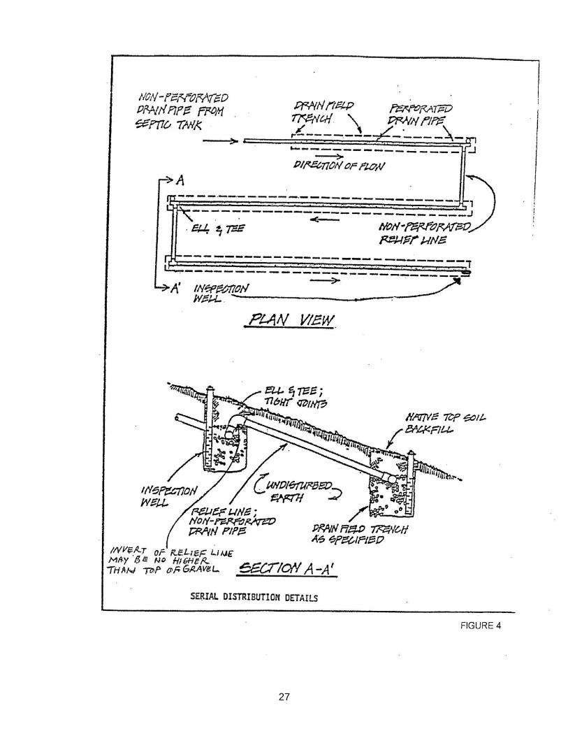
245 Serial Distribution: An arrangement of an absorption area in which the lines are connected consecutively
to receive the flow of sewage one after another. It is most useful for hillside locations. 246 Service Provider: A qualified individual with knowledge and competency in the onsite wastewater
treatment system operation, maintenance and monitoring. This knowledge may be gained through experience and/or education. The individual must also possess up-to-date certification from the National Sanitation Foundation, the Consortium of Institutes for Decentralized Wastewater Treatment, National Onsite Wastewater Recycling Association, National Association of Wastewater Transporters or completion of California Onsite Wastewater Association’s Onsite Wastewater Inspection Level II Program.
247 Setback: The minimum horizontal distance from any point along the outside edge of a septic tank or the
edge of a drainfield trench, mound, etc., to any point on the described site feature. 248 Silt: Individual mineral particles in a soil that range in diameter from the upper limit of clay (0.002
millimeter) to the lower limit of very fine sand (0.05 millimeter). Soil of the silt textural class is 80 percent or more silt and less than 12 percent clay.
249 Soil: The unconsolidated material on the surface of the earth that exhibits properties and characteristics
that are a product of the combined factors of parent material, climate, living organisms, topography, and time.
250 Soil Absorption System: See Drainfield. 251 Soil Depth: The combined thickness of adjacent soil layers that are suitable for effluent filtration. Soil depth
is measured vertically to bedrock, hardpan, or an impermeable soil layer. 252 Soil Horizon or Layer: A layer of soil differing from adjacent (underlying or overlying) layers in some
property or characteristic. Differences include, but are not limited to, color, texture, pH, rock content, structure, and porosity.
253 Soil Texture: The relative proportions of sand, silt, and clay as defined by the classes of the soil textural
triangle (U.S. Department of Agriculture). The basic textural classes in order of increasing proportion of fine particles are sand, loamy sand, sandy loam, loam, silt loan, silt, sandy clay loam, clay loam, silty clay loam, sandy clay, silty clay and clay. Textural classes may be modified when coarse fragments are present in sufficient number, i.e., gravelly sandy loam, cobbly clay, etc.
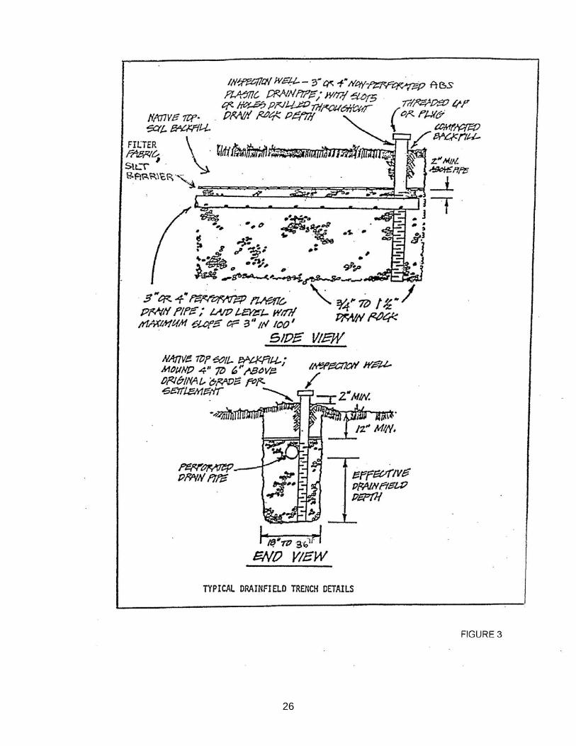
254 Standard Leaching Trenches: Lateral sewage disposal lines containing aggregate or gravelless
chambers and perforated pipe for storage and dispersal of wastewater into the soil absorption area. Leaching trenches are designed in accordance with standard practice and Section 603 C of these Regulations. Refer to Figure 3.
255 Subsurface Drip Dispersal System: A method of subsurface effluent dispersal using shallow distribution
in combination with pressurized, low-flow drip emitters.
6
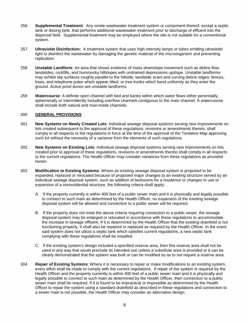
256 Supplemental Treatment: Any onsite wastewater treatment system or component thereof, except a septic tank or dosing tank, that performs additional wastewater treatment prior to discharge of effluent into the dispersal field. Supplemental treatment may be employed where the site is not suitable for a conventional system.
257 Ultraviolet Disinfection: A treatment system that uses high intensity lamps or tubes emitting ultraviolet
light to disinfect the wastewater by damaging the genetic material of the microorganism and preventing replication.
258 Unstable Landform: An area that shows evidence of mass downslope movement such as debris flow,
landslides, rockfills, and hummocky hillslopes with undrained depressions upslope. Unstable landforms may exhibit slip surfaces roughly parallel to the hillside; landslide scars and curving debris ridges; fences, trees, and telephone poles which appear tilted; or tree trunks which bend uniformly as they enter the ground. Active pond dunes are unstable landforms.
259 Watercourse: A definite open channel with bed and banks within which water flows either perennially,
ephemerally or intermittently including overflow channels contiguous to the main channel. A watercourse shall include both natural and man-made channels.
300 GENERAL PROVISIONS 301 New Systems on Newly Created Lots: Individual sewage disposal systems serving new improvements on
lots created subsequent to the approval of these regulations, revisions or amendments thereto, shall comply in all respects to the regulations in force at the time of the approval of the Tentative Map approving such lot without the necessity of a variance from the elements of such regulations.
302 New Systems on Existing Lots: Individual sewage disposal systems serving new improvements on lots
created prior to approval of these regulations, revisions or amendments thereto shall comply in all respects to the current regulations. The Health Officer may consider variances from these regulations as provided herein.
303 Modification to Existing Systems: Where an existing sewage disposal system is proposed to be
expanded, replaced or relocated because of proposed major changes to an existing structure served by an individual sewage disposal system, such as addition of bedrooms for a residence or changes in use or expansion of a nonresidential structure, the following criteria shall apply:
A. If the property currently is within 400 feet of a public sewer main and it is physically and legally possible to connect to such main as determined by the Health Officer, no expansion of the existing sewage disposal system will be allowed and connection to a public sewer will be required. B. If the property does not meet the above criteria requiring connection to a public sewer, the sewage disposal system may be enlarged or relocated in accordance with these regulations to accommodate the increase in sewage effluent. If it is determined by the Health Officer that the existing drainfield is not functioning properly, it shall also be repaired or replaced as required by the Health Officer. In the event said system does not utilize a septic tank which satisfies current regulations, a new septic tank complying with these regulations shall be installed.
C. If the existing system's design included a specified reserve area, then this reserve area shall not be used in any way that would preclude its intended use unless a substitute area is provided or it can be clearly demonstrated that the system was built or can be modified so as to not require a reserve area.
304 Repair of Existing Systems: Where it is necessary to repair or make modifications to an existing system,
every effort shall be made to comply with the current regulations. If repair of the system is required by the Health Officer and the property currently is within 400 feet of a public sewer main and it is physically and legally possible to connect to such main as determined by the Health Officer, then connection to a public sewer main shall be required. If it is found to be impractical or impossible as determined by the Health Officer to repair the system using a standard drainfield as described in these regulations and connection to a sewer main is not possible, the Health Officer may consider an alternative design.
7
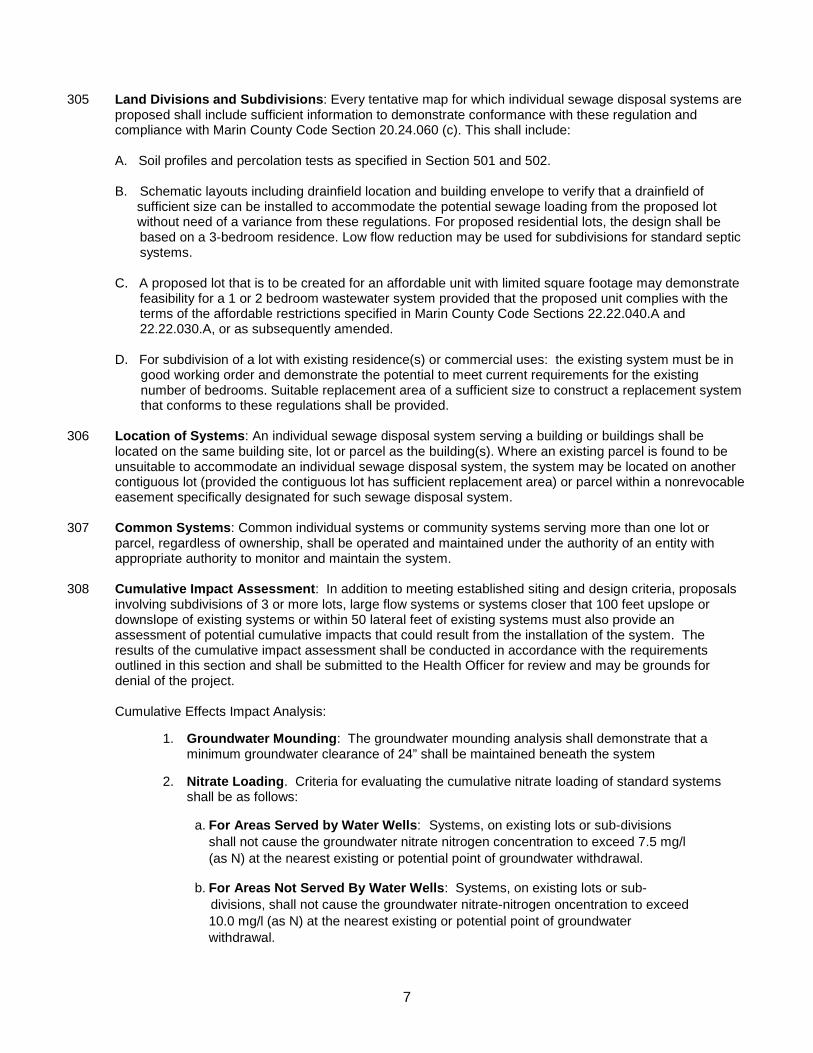
305 Land Divisions and Subdivisions: Every tentative map for which individual sewage disposal systems are
proposed shall include sufficient information to demonstrate conformance with these regulation and compliance with Marin County Code Section 20.24.060 (c). This shall include:
A. Soil profiles and percolation tests as specified in Section 501 and 502.
B. Schematic layouts including drainfield location and building envelope to verify that a drainfield of sufficient size can be installed to accommodate the potential sewage loading from the proposed lot without need of a variance from these regulations. For proposed residential lots, the design shall be
based on a 3-bedroom residence. Low flow reduction may be used for subdivisions for standard septic systems.
C. A proposed lot that is to be created for an affordable unit with limited square footage may demonstrate feasibility for a 1 or 2 bedroom wastewater system provided that the proposed unit complies with the terms of the affordable restrictions specified in Marin County Code Sections 22.22.040.A and 22.22.030.A, or as subsequently amended.
D. For subdivision of a lot with existing residence(s) or commercial uses: the existing system must be in good working order and demonstrate the potential to meet current requirements for the existing number of bedrooms. Suitable replacement area of a sufficient size to construct a replacement system that conforms to these regulations shall be provided.
306 Location of Systems: An individual sewage disposal system serving a building or buildings shall be located on the same building site, lot or parcel as the building(s). Where an existing parcel is found to be unsuitable to accommodate an individual sewage disposal system, the system may be located on another contiguous lot (provided the contiguous lot has sufficient replacement area) or parcel within a nonrevocable easement specifically designated for such sewage disposal system.
307 Common Systems: Common individual systems or community systems serving more than one lot or
parcel, regardless of ownership, shall be operated and maintained under the authority of an entity with appropriate authority to monitor and maintain the system.
308 Cumulative Impact Assessment: In addition to meeting established siting and design criteria, proposals
involving subdivisions of 3 or more lots, large flow systems or systems closer that 100 feet upslope or downslope of existing systems or within 50 lateral feet of existing systems must also provide an assessment of potential cumulative impacts that could result from the installation of the system. The results of the cumulative impact assessment shall be conducted in accordance with the requirements outlined in this section and shall be submitted to the Health Officer for review and may be grounds for denial of the project.
Cumulative Effects Impact Analysis:
1. Groundwater Mounding: The groundwater mounding analysis shall demonstrate that a minimum groundwater clearance of 24” shall be maintained beneath the system
2. Nitrate Loading. Criteria for evaluating the cumulative nitrate loading of standard systems
shall be as follows:
a. For Areas Served by Water Wells: Systems, on existing lots or sub-divisions shall not cause the groundwater nitrate nitrogen concentration to exceed 7.5 mg/l (as N) at the nearest existing or potential point of groundwater withdrawal.
b. For Areas Not Served By Water Wells: Systems, on existing lots or sub-
divisions, shall not cause the groundwater nitrate-nitrogen oncentration to exceed 10.0 mg/l (as N) at the nearest existing or potential point of groundwater withdrawal.
8
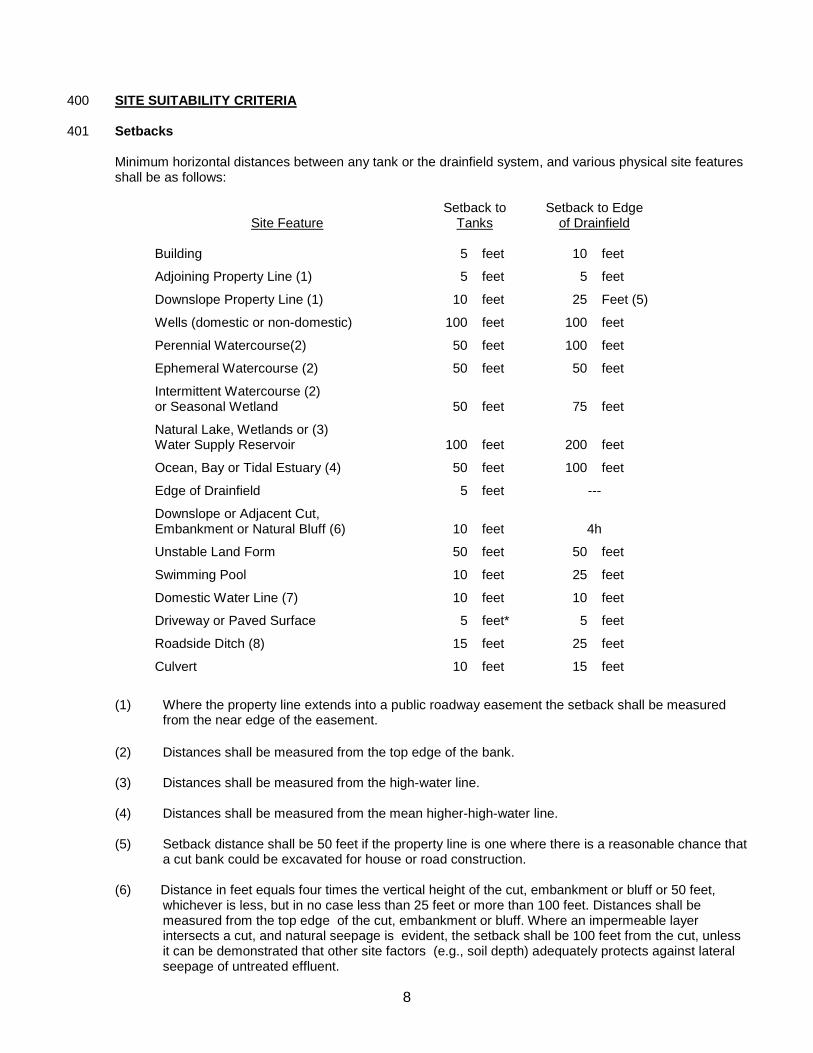
400 SITE SUITABILITY CRITERIA 401 Setbacks
Minimum horizontal distances between any tank or the drainfield system, and various physical site features shall be as follows:
Site Feature
Setback to Tanks
Setback to Edge of Drainfield
Building 5 feet 10 feet
Adjoining Property Line (1) 5 feet 5 feet
Downslope Property Line (1) 10 feet 25 Feet (5)
Wells (domestic or non-domestic) 100 feet 100 feet
Perennial Watercourse(2) 50 feet 100 feet
Ephemeral Watercourse (2) 50 feet 50 feet
Intermittent Watercourse (2) or Seasonal Wetland
50 feet 75 feet
Natural Lake, Wetlands or (3) Water Supply Reservoir
100 feet 200 feet
Ocean, Bay or Tidal Estuary (4) 50 feet 100 feet
Edge of Drainfield 5 feet ---
Downslope or Adjacent Cut, Embankment or Natural Bluff (6)
10 feet 4h
Unstable Land Form 50 feet 50 feet
Swimming Pool 10 feet 25 feet
Domestic Water Line (7) 10 feet 10 feet
Driveway or Paved Surface 5 feet* 5 feet
Roadside Ditch (8) 15 feet 25 feet
Culvert 10 feet 15 feet
(1) Where the property line extends into a public roadway easement the setback shall be measured
from the near edge of the easement. (2) Distances shall be measured from the top edge of the bank. (3) Distances shall be measured from the high-water line. (4) Distances shall be measured from the mean higher-high-water line. (5) Setback distance shall be 50 feet if the property line is one where there is a reasonable chance that
a cut bank could be excavated for house or road construction. (6) Distance in feet equals four times the vertical height of the cut, embankment or bluff or 50 feet,
whichever is less, but in no case less than 25 feet or more than 100 feet. Distances shall be measured from the top edge of the cut, embankment or bluff. Where an impermeable layer intersects a cut, and natural seepage is evident, the setback shall be 100 feet from the cut, unless it can be demonstrated that other site factors (e.g., soil depth) adequately protects against lateral seepage of untreated effluent.
9
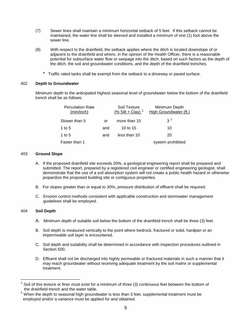
(7) Sewer lines shall maintain a minimum horizontal setback of 5 feet. If this setback cannot be
maintained, the water line shall be sleeved and installed a minimum of one (1) foot above the sewer line.
(8) With respect to the drainfield, the setback applies where the ditch is located downslope of or
adjacent to the drainfield and where, in the opinion of the Health Officer, there is a reasonable potential for subsurface water flow or seepage into the ditch, based on such factors as the depth of the ditch, the soil and groundwater conditions, and the depth of the drainfield trenches.
* Traffic rated tanks shall be exempt from the setback to a driveway or paved surface.
402 Depth to Groundwater
Minimum depth to the anticipated highest seasonal level of groundwater below the bottom of the drainfield trench shall be as follows:
Percolation Rate
(min/inch) Soil Texture
(% Silt + Clay) 1 Minimum Depth
High Groundwater (ft.)
Slower than 5
or
more than 15
3 2
1 to 5 and 10 to 15 10
1 to 5 and less than 10 20
Faster than 1 system prohibited
403 Ground Slope
A. If the proposed drainfield site exceeds 20%, a geological engineering report shall be prepared and submitted. The report, prepared by a registered civil engineer or certified engineering geologist, shall demonstrate that the use of a soil absorption system will not create a public health hazard or otherwise jeopardize the proposed building site or contiguous properties.
B. For slopes greater than or equal to 30%, pressure distribution of effluent shall be required. C. Erosion control methods consistent with applicable construction and stormwater management
guidelines shall be employed. 404 Soil Depth A. Minimum depth of suitable soil below the bottom of the drainfield trench shall be three (3) feet.
B. Soil depth is measured vertically to the point where bedrock, fractured or solid, hardpan or an impermeable soil layer is encountered.
C. Soil depth and suitability shall be determined in accordance with inspection procedures outlined in
Section 500.
D. Effluent shall not be discharged into highly permeable or fractured materials in such a manner that it may reach groundwater without receiving adequate treatment by the soil matrix or supplemental treatment.
1 Soil of this texture or finer must exist for a minimum of three (3) continuous feet between the bottom of the drainfield trench and the water table. 2 When the depth to seasonal high groundwater is less than 3 feet, supplemental treatment must be employed and/or a variance must be applied for and obtained.
10
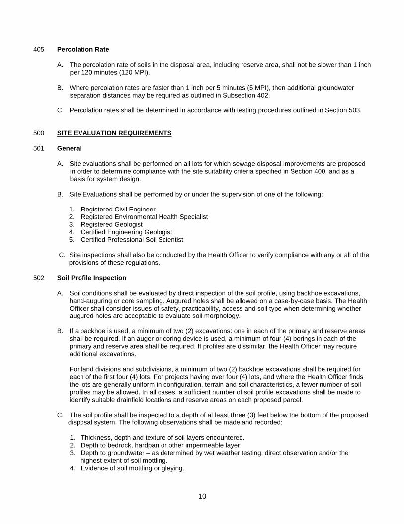
405 Percolation Rate
A. The percolation rate of soils in the disposal area, including reserve area, shall not be slower than 1 inch per 120 minutes (120 MPI). B. Where percolation rates are faster than 1 inch per 5 minutes (5 MPI), then additional groundwater separation distances may be required as outlined in Subsection 402. C. Percolation rates shall be determined in accordance with testing procedures outlined in Section 503.
500 SITE EVALUATION REQUIREMENTS 501 General
A. Site evaluations shall be performed on all lots for which sewage disposal improvements are proposed in order to determine compliance with the site suitability criteria specified in Section 400, and as a basis for system design.
B. Site Evaluations shall be performed by or under the supervision of one of the following:
1. Registered Civil Engineer 2. Registered Environmental Health Specialist 3. Registered Geologist 4. Certified Engineering Geologist 5. Certified Professional Soil Scientist
C. Site inspections shall also be conducted by the Health Officer to verify compliance with any or all of the
provisions of these regulations. 502 Soil Profile Inspection
A. Soil conditions shall be evaluated by direct inspection of the soil profile, using backhoe excavations, hand-auguring or core sampling. Augured holes shall be allowed on a case-by-case basis. The Health Officer shall consider issues of safety, practicability, access and soil type when determining whether augured holes are acceptable to evaluate soil morphology.
B. If a backhoe is used, a minimum of two (2) excavations: one in each of the primary and reserve areas
shall be required. If an auger or coring device is used, a minimum of four (4) borings in each of the primary and reserve area shall be required. If profiles are dissimilar, the Health Officer may require additional excavations.
For land divisions and subdivisions, a minimum of two (2) backhoe excavations shall be required for each of the first four (4) lots. For projects having over four (4) lots, and where the Health Officer finds the lots are generally uniform in configuration, terrain and soil characteristics, a fewer number of soil profiles may be allowed. In all cases, a sufficient number of soil profile excavations shall be made to identify suitable drainfield locations and reserve areas on each proposed parcel.
C. The soil profile shall be inspected to a depth of at least three (3) feet below the bottom of the proposed disposal system. The following observations shall be made and recorded: 1. Thickness, depth and texture of soil layers encountered. 2. Depth to bedrock, hardpan or other impermeable layer. 3. Depth to groundwater – as determined by wet weather testing, direct observation and/or the
highest extent of soil mottling. 4. Evidence of soil mottling or gleying.
11
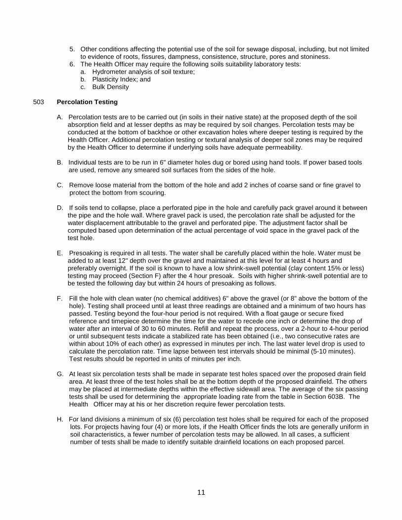
5. Other conditions affecting the potential use of the soil for sewage disposal, including, but not limited to evidence of roots, fissures, dampness, consistence, structure, pores and stoniness. 6. The Health Officer may require the following soils suitability laboratory tests:
a. Hydrometer analysis of soil texture; b. Plasticity Index; and c. Bulk Density
503 Percolation Testing
A. Percolation tests are to be carried out (in soils in their native state) at the proposed depth of the soil absorption field and at lesser depths as may be required by soil changes. Percolation tests may be conducted at the bottom of backhoe or other excavation holes where deeper testing is required by the Health Officer. Additional percolation testing or textural analysis of deeper soil zones may be required by the Health Officer to determine if underlying soils have adequate permeability. B. Individual tests are to be run in 6" diameter holes dug or bored using hand tools. If power based tools
are used, remove any smeared soil surfaces from the sides of the hole. C. Remove loose material from the bottom of the hole and add 2 inches of coarse sand or fine gravel to protect the bottom from scouring. D. If soils tend to collapse, place a perforated pipe in the hole and carefully pack gravel around it between the pipe and the hole wall. Where gravel pack is used, the percolation rate shall be adjusted for the water displacement attributable to the gravel and perforated pipe. The adjustment factor shall be computed based upon determination of the actual percentage of void space in the gravel pack of the test hole. E. Presoaking is required in all tests. The water shall be carefully placed within the hole. Water must be added to at least 12" depth over the gravel and maintained at this level for at least 4 hours and preferably overnight. If the soil is known to have a low shrink-swell potential (clay content 15% or less) testing may proceed (Section F) after the 4 hour presoak. Soils with higher shrink-swell potential are to be tested the following day but within 24 hours of presoaking as follows. F. Fill the hole with clean water (no chemical additives) 6" above the gravel (or 8" above the bottom of the
hole). Testing shall proceed until at least three readings are obtained and a minimum of two hours has passed. Testing beyond the four-hour period is not required. With a float gauge or secure fixed reference and timepiece determine the time for the water to recede one inch or determine the drop of water after an interval of 30 to 60 minutes. Refill and repeat the process, over a 2-hour to 4-hour period or until subsequent tests indicate a stabilized rate has been obtained (i.e., two consecutive rates are within about 10% of each other) as expressed in minutes per inch. The last water level drop is used to calculate the percolation rate. Time lapse between test intervals should be minimal (5-10 minutes). Test results should be reported in units of minutes per inch.
G. At least six percolation tests shall be made in separate test holes spaced over the proposed drain field
area. At least three of the test holes shall be at the bottom depth of the proposed drainfield. The others may be placed at intermediate depths within the effective sidewall area. The average of the six passing tests shall be used for determining the appropriate loading rate from the table in Section 603B. The Health Officer may at his or her discretion require fewer percolation tests.
H. For land divisions a minimum of six (6) percolation test holes shall be required for each of the proposed
lots. For projects having four (4) or more lots, if the Health Officer finds the lots are generally uniform in soil characteristics, a fewer number of percolation tests may be allowed. In all cases, a sufficient number of tests shall be made to identify suitable drainfield locations on each proposed parcel.
12
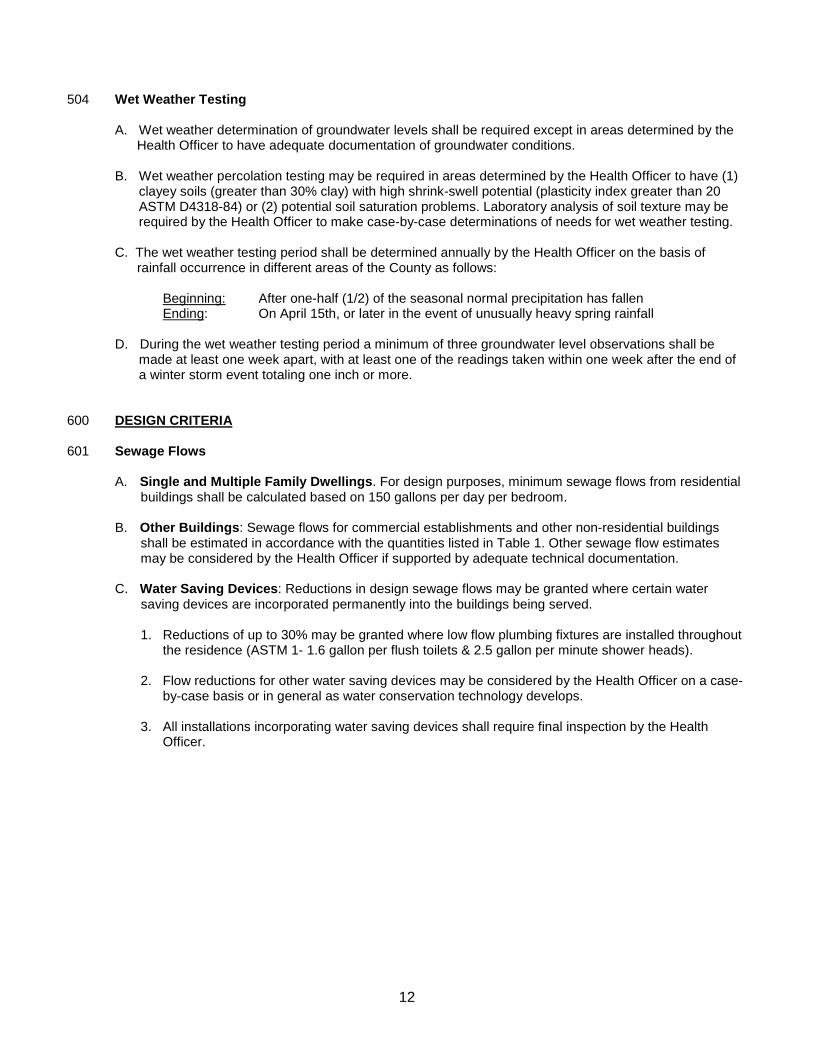
504 Wet Weather Testing
A. Wet weather determination of groundwater levels shall be required except in areas determined by the Health Officer to have adequate documentation of groundwater conditions. B. Wet weather percolation testing may be required in areas determined by the Health Officer to have (1)
clayey soils (greater than 30% clay) with high shrink-swell potential (plasticity index greater than 20 ASTM D4318-84) or (2) potential soil saturation problems. Laboratory analysis of soil texture may be required by the Health Officer to make case-by-case determinations of needs for wet weather testing.
C. The wet weather testing period shall be determined annually by the Health Officer on the basis of
rainfall occurrence in different areas of the County as follows:
Beginning: After one-half (1/2) of the seasonal normal precipitation has fallen Ending: On April 15th, or later in the event of unusually heavy spring rainfall
D. During the wet weather testing period a minimum of three groundwater level observations shall be
made at least one week apart, with at least one of the readings taken within one week after the end of a winter storm event totaling one inch or more.
600 DESIGN CRITERIA 601 Sewage Flows
A. Single and Multiple Family Dwellings. For design purposes, minimum sewage flows from residential buildings shall be calculated based on 150 gallons per day per bedroom. B. Other Buildings: Sewage flows for commercial establishments and other non-residential buildings shall be estimated in accordance with the quantities listed in Table 1. Other sewage flow estimates may be considered by the Health Officer if supported by adequate technical documentation. C. Water Saving Devices: Reductions in design sewage flows may be granted where certain water
saving devices are incorporated permanently into the buildings being served. 1. Reductions of up to 30% may be granted where low flow plumbing fixtures are installed throughout
the residence (ASTM 1- 1.6 gallon per flush toilets & 2.5 gallon per minute shower heads). 2. Flow reductions for other water saving devices may be considered by the Health Officer on a case-
by-case basis or in general as water conservation technology develops. 3. All installations incorporating water saving devices shall require final inspection by the Health
Officer.
13
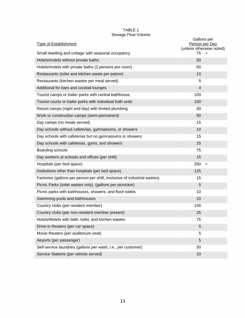
TABLE 1
Sewage Flow Volume
Type of Establishment Gallons per
Person per Day (unless otherwise noted)
Small dwelling and cottage with seasonal occupancy 75 +
Hotels/motels without private baths 50
Hotels/motels with private baths (2 persons per room) 60
Restaurants (toilet and kitchen waste per patron) 10
Restaurants (kitchen wastes per meal served) 5
Additional for bars and cocktail lounges 4
Tourist camps or trailer parks with central bathhouse 100
Tourist courts or trailer parks with individual bath units 150
Resort camps (night and day) with limited plumbing 40
Work or construction camps (semi-permanent) 50
Day camps (no meals served) 15
Day schools without cafeterias, gymnasiums, or showers 10
Day schools with cafeterias but no gymnasiums or showers 15
Day schools with cafeterias, gyms, and showers 25
Boarding schools 75
Day workers at schools and offices (per shift) 15
Hospitals (per bed space) 250 +
Institutions other than hospitals (per bed space) 125
Factories (gallons per person per shift, exclusive of industrial wastes) 15
Picnic Parks (toilet wastes only), (gallons per picnicker) 5
Picnic parks with bathhouses, showers, and flush toilets 10
Swimming pools and bathhouses 10
Country clubs (per resident member) 100
Country clubs (per non-resident member present) 25
Hotels/Motels with bath, toilet, and kitchen wastes 75
Drive-in theaters (per car space) 5
Movie theaters (per auditorium seat) 5
Airports (per passenger) 5
Self-service laundries (gallons per wash, i.e., per customer) 50
Service Stations (per vehicle served) 10
14
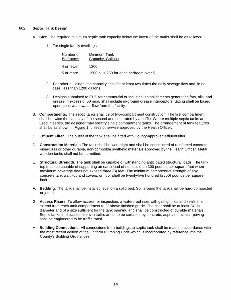
602 Septic Tank Design A. Size. The required minimum septic tank capacity below the invert of the outlet shall be as follows: 1. For single family dwellings:
Number of Bedrooms
Minimum Tank Capacity, Gallons
4 or fewer
1200
5 or more 1500 plus 250 for each bedroom over 5
2. For other buildings, the capacity shall be at least two times the daily sewage flow and, in no case, less than 1200 gallons. 3. Designs submitted to EHS for commercial or industrial establishments generating fats, oils, and
grease in excess of 50 mg/L shall include in-ground grease interceptors. Sizing shall be based upon peak wastewater flow from the facility.
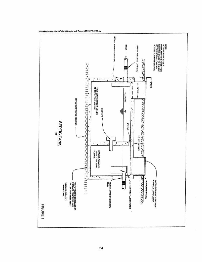
B. Compartments. The septic tanks shall be of two-compartment construction. The first compartment
shall be twice the capacity of the second and separated by a baffle. Where multiple septic tanks are used in series, the designer may specify single compartment tanks. The arrangement of tank features shall be as shown in Figure 1, unless otherwise approved by the Health Officer.
C. Effluent Filter. The outlet of the tank shall be fitted with County-approved effluent filter. D. Construction Materials The tank shall be watertight and shall be constructed of reinforced concrete,
Fiberglass or other durable, non-corrodible synthetic materials approved by the Health Officer. Metal wooden tanks shall not be permitted.
E. Structural Strength. The tank shall be capable of withstanding anticipated structural loads. The tank top must be capable of supporting an earth load of not less than 300 pounds per square foot when maximum coverage does not exceed three (3) feet. The minimum compressive strength of any concrete tank wall, top and covers, or floor shall be twenty-five hundred (2500) pounds per square inch. F. Bedding. The tank shall be installed level on a solid bed. Soil around the tank shall be hard-compacted
or jetted.
G. Access Risers. To allow access for inspection, a waterproof riser with gastight lids and seals shall extend from each tank compartment to 2” above finished grade. The riser shall be at least 24” in diameter and of a size sufficient for the tank opening and shall be constructed of durable materials. Septic tanks and access risers in traffic areas to be surfaced by concrete, asphalt or similar paving shall be engineered to be traffic rated.
H. Building Connections. All connections from buildings to septic tank shall be made in accordance with the most recent edition of the Uniform Plumbing Code which is incorporated by reference into the County's Building Ordinances.
15
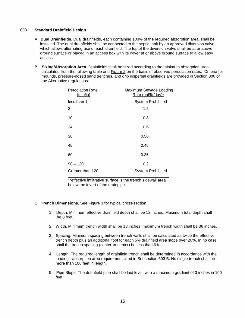
603 Standard Drainfield Design
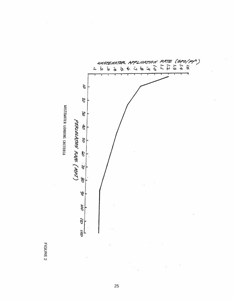
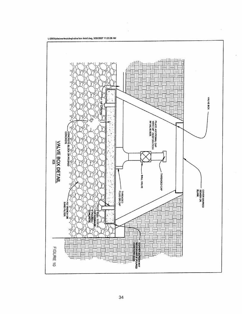
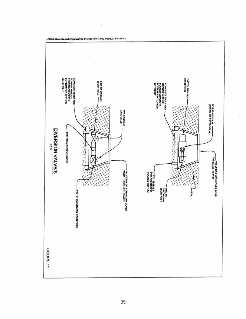
A. Dual Drainfields. Dual drainfields, each containing 100% of the required absorption area, shall be installed. The dual drainfields shall be connected to the septic tank by an approved diversion valve which allows alternating use of each drainfield. The top of the diversion valve shall be at or above ground surface or placed in an access box with its cover at or above ground surface to allow easy access. B. Sizing/Absorption Area. Drainfields shall be sized according to the minimum absorption area
calculated from the following table and Figure 2 on the basis of observed percolation rates. Criteria for mounds, pressure-dosed sand trenches, and drip dispersal drainfields are provided in Section 800 of the Alternative regulations.
Percolation Rate (min/in)
Maximum Sewage Loading Rate (gal/ft2/day)*
less than 1 System Prohibited
3 1.2
10 0.8
24 0.6
30 0.56
45 0.45
60 0.35
90 – 120 0.2
Greater than 120 System Prohibited **effective infiltrative surface is the trench sidewall area below the invert of the drainpipe.
C. Trench Dimensions. See Figure 3 for typical cross-section
1. Depth. Minimum effective drainfield depth shall be 12 inches. Maximum total depth shall be 8 feet. 2. Width. Minimum trench width shall be 18 inches; maximum trench width shall be 36 inches.
3. Spacing. Minimum spacing between trench walls shall be calculated as twice the effective trench depth plus an additional foot for each 5% drainfield area slope over 20%. In no case shall the trench spacing (center-to-center) be less than 6 feet. 4. Length. The required length of drainfield trench shall be determined in accordance with the loading - absorption area requirement cited in Subsection 603 B. No single trench shall be more than 100 feet in length. 5. Pipe Slope. The drainfield pipe shall be laid level, with a maximum gradient of 3 inches in 100 feet.
16
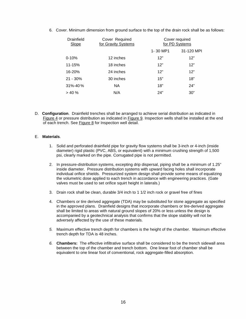
6. Cover. Minimum dimension from ground surface to the top of the drain rock shall be as follows:
Drainfield Slope
Cover Required for Gravity Systems
Cover required for PD Systems
1- 30 MP1 31-120 MPI
0-10% 12 inches 12” 12”
11-15% 18 inches 12” 12”
16-20% 24 inches 12” 12”
21 - 30% 30 inches 15” 18”
31%-40 % NA 18” 24”
> 40 % N/A 24” 30”
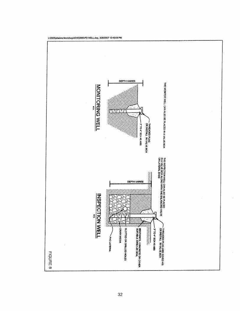
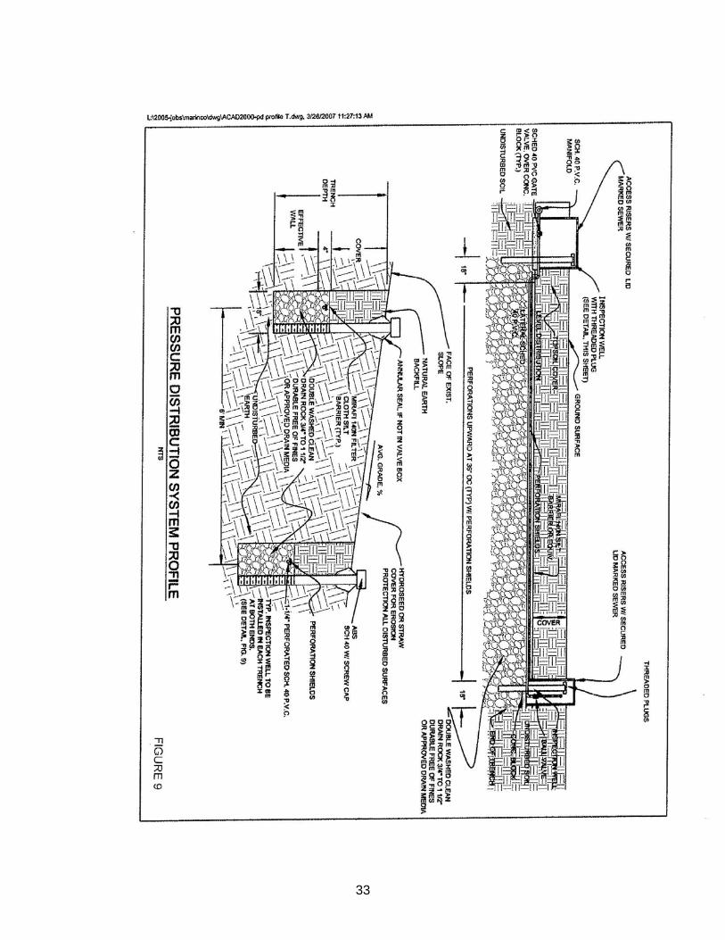
D. Configuration. Drainfield trenches shall be arranged to achieve serial distribution as indicated in Figure 4 or pressure distribution as indicated in Figure 9. Inspection wells shall be installed at the end of each trench. See Figure 8 for Inspection well detail.
E. Materials.
1. Solid and perforated drainfield pipe for gravity flow systems shall be 3-inch or 4-inch (inside diameter) rigid plastic (PVC, ABS, or equivalent) with a minimum crushing strength of 1,500 psi, clearly marked on the pipe. Corrugated pipe is not permitted.
2. In pressure-distribution systems, excepting drip dispersal, piping shall be a minimum of 1.25”
inside diameter. Pressure distribution systems with upward facing holes shall incorporate individual orifice shields. Pressurized system design shall provide some means of equalizing the volumetric dose applied to each trench in accordance with engineering practices. (Gate valves must be used to set orifice squirt height in laterals.)
3. Drain rock shall be clean, durable 3/4 inch to 1 1/2 inch rock or gravel free of fines
4. Chambers or tire derived aggregate (TDA) may be substituted for stone aggregate as specified
in the approved plans. Drainfield designs that incorporate chambers or tire-derived aggregate shall be limited to areas with natural ground slopes of 20% or less unless the design is accompanied by a geotechnical analysis that confirms that the slope stability will not be adversely affected by the use of these materials.
5. Maximum effective trench depth for chambers is the height of the chamber. Maximum effective
trench depth for TDA is 48 inches.
6. Chambers: The effective infiltrative surface shall be considered to be the trench sidewall area between the top of the chamber and trench bottom. One linear foot of chamber shall be equivalent to one linear foot of conventional, rock aggregate-filled absorption.
17
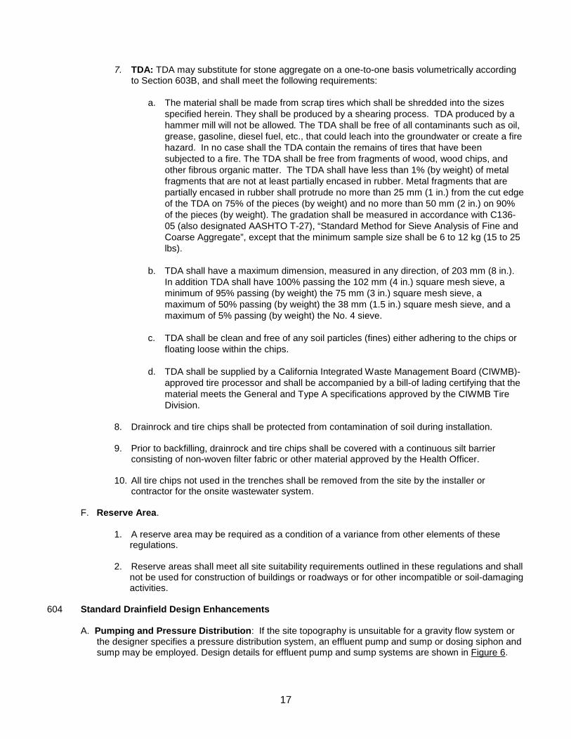
7. TDA: TDA may substitute for stone aggregate on a one-to-one basis volumetrically according
to Section 603B, and shall meet the following requirements:
a. The material shall be made from scrap tires which shall be shredded into the sizes specified herein. They shall be produced by a shearing process. TDA produced by a hammer mill will not be allowed. The TDA shall be free of all contaminants such as oil, grease, gasoline, diesel fuel, etc., that could leach into the groundwater or create a fire hazard. In no case shall the TDA contain the remains of tires that have been subjected to a fire. The TDA shall be free from fragments of wood, wood chips, and other fibrous organic matter. The TDA shall have less than 1% (by weight) of metal fragments that are not at least partially encased in rubber. Metal fragments that are partially encased in rubber shall protrude no more than 25 mm (1 in.) from the cut edge of the TDA on 75% of the pieces (by weight) and no more than 50 mm (2 in.) on 90% of the pieces (by weight). The gradation shall be measured in accordance with C136-05 (also designated AASHTO T-27), “Standard Method for Sieve Analysis of Fine and Coarse Aggregate”, except that the minimum sample size shall be 6 to 12 kg (15 to 25 lbs).
b. TDA shall have a maximum dimension, measured in any direction, of 203 mm (8 in.). In addition TDA shall have 100% passing the 102 mm (4 in.) square mesh sieve, a minimum of 95% passing (by weight) the 75 mm (3 in.) square mesh sieve, a maximum of 50% passing (by weight) the 38 mm (1.5 in.) square mesh sieve, and a maximum of 5% passing (by weight) the No. 4 sieve.
c. TDA shall be clean and free of any soil particles (fines) either adhering to the chips or floating loose within the chips.
d. TDA shall be supplied by a California Integrated Waste Management Board (CIWMB)-approved tire processor and shall be accompanied by a bill-of lading certifying that the material meets the General and Type A specifications approved by the CIWMB Tire Division.
8. Drainrock and tire chips shall be protected from contamination of soil during installation.
9. Prior to backfilling, drainrock and tire chips shall be covered with a continuous silt barrier
consisting of non-woven filter fabric or other material approved by the Health Officer.
10. All tire chips not used in the trenches shall be removed from the site by the installer or contractor for the onsite wastewater system.
F. Reserve Area.
1. A reserve area may be required as a condition of a variance from other elements of these regulations. 2. Reserve areas shall meet all site suitability requirements outlined in these regulations and shall not be used for construction of buildings or roadways or for other incompatible or soil-damaging activities.
604 Standard Drainfield Design Enhancements
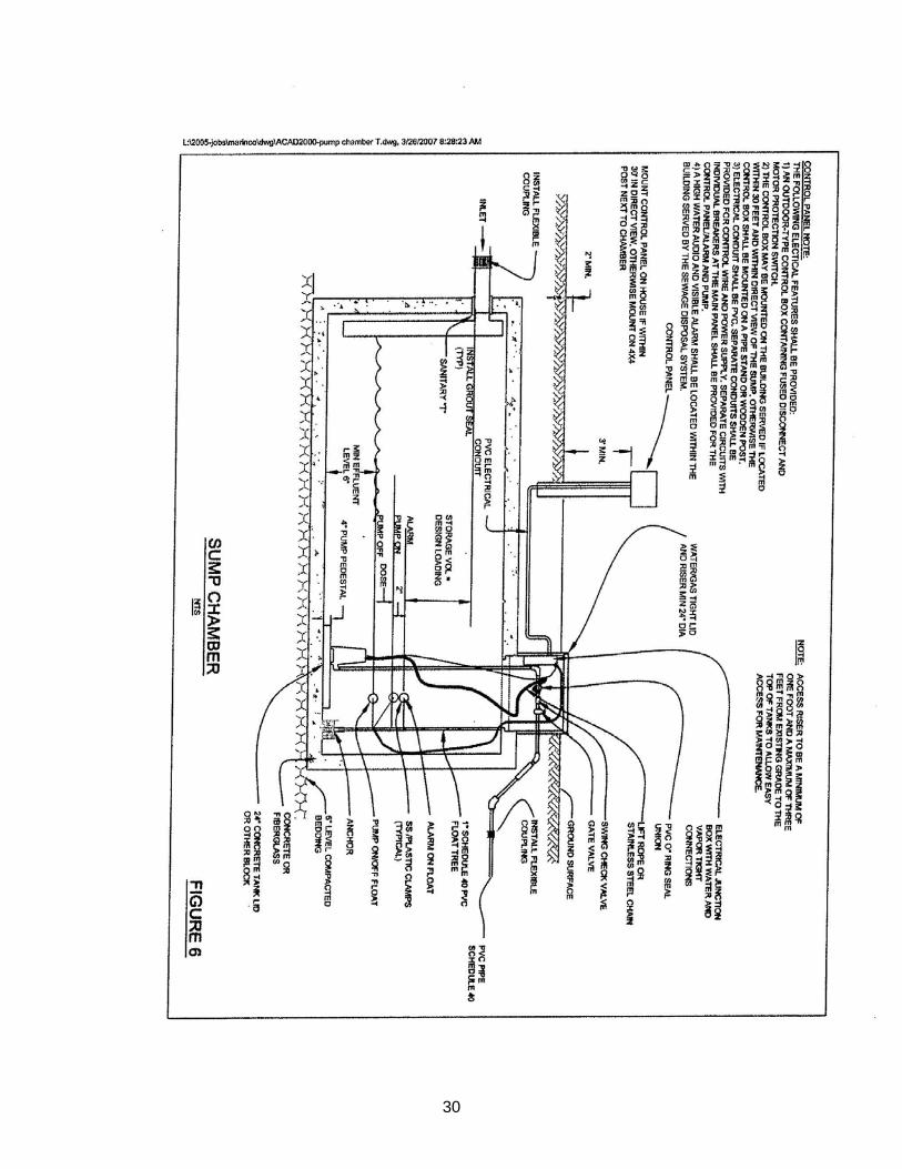
A. Pumping and Pressure Distribution: If the site topography is unsuitable for a gravity flow system or the designer specifies a pressure distribution system, an effluent pump and sump or dosing siphon and sump may be employed. Design details for effluent pump and sump systems are shown in Figure 6.
18
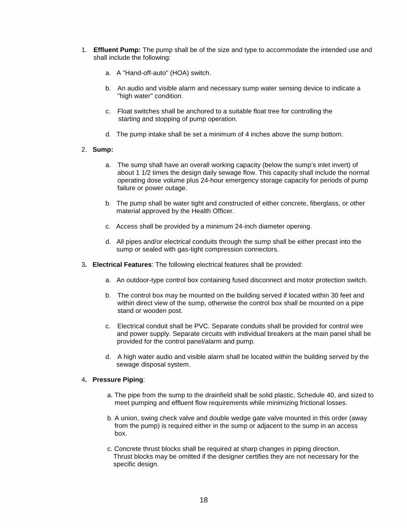
1. Effluent Pump: The pump shall be of the size and type to accommodate the intended use and
shall include the following: a. A "Hand-off-auto" (HOA) switch.
b. An audio and visible alarm and necessary sump water sensing device to indicate a "high water" condition.
c. Float switches shall be anchored to a suitable float tree for controlling the starting and stopping of pump operation. d. The pump intake shall be set a minimum of 4 inches above the sump bottom.
2. Sump:
a. The sump shall have an overall working capacity (below the sump’s inlet invert) of about 1 1/2 times the design daily sewage flow. This capacity shall include the normal operating dose volume plus 24-hour emergency storage capacity for periods of pump failure or power outage.
b. The pump shall be water tight and constructed of either concrete, fiberglass, or other material approved by the Health Officer.
c. Access shall be provided by a minimum 24-inch diameter opening. d. All pipes and/or electrical conduits through the sump shall be either precast into the sump or sealed with gas-tight compression connectors.
3. Electrical Features: The following electrical features shall be provided: a. An outdoor-type control box containing fused disconnect and motor protection switch.
b. The control box may be mounted on the building served if located within 30 feet and
within direct view of the sump, otherwise the control box shall be mounted on a pipe stand or wooden post.
c. Electrical conduit shall be PVC. Separate conduits shall be provided for control wire
and power supply. Separate circuits with individual breakers at the main panel shall be provided for the control panel/alarm and pump.
d. A high water audio and visible alarm shall be located within the building served by the sewage disposal system.
4. Pressure Piping:
a. The pipe from the sump to the drainfield shall be solid plastic, Schedule 40, and sized to meet pumping and effluent flow requirements while minimizing frictional losses. b. A union, swing check valve and double wedge gate valve mounted in this order (away from the pump) is required either in the sump or adjacent to the sump in an access box. c. Concrete thrust blocks shall be required at sharp changes in piping direction.
Thrust blocks may be omitted if the designer certifies they are not necessary for the specific design.
19
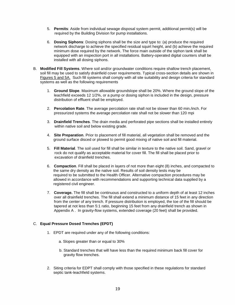
5. Permits: Aside from individual sewage disposal system permit, additional permit(s) will be required by the Building Division for pump installations. 6. Dosing Siphons: Dosing siphons shall be the size and type to: (a) produce the required
network discharge to achieve the specified residual squirt height, and (b) achieve the required minimum dose required by the network. The force main outside of the siphon tank shall be equipped with an inspection port in all installations. Battery-operated digital counters shall be installed with all dosing siphons.
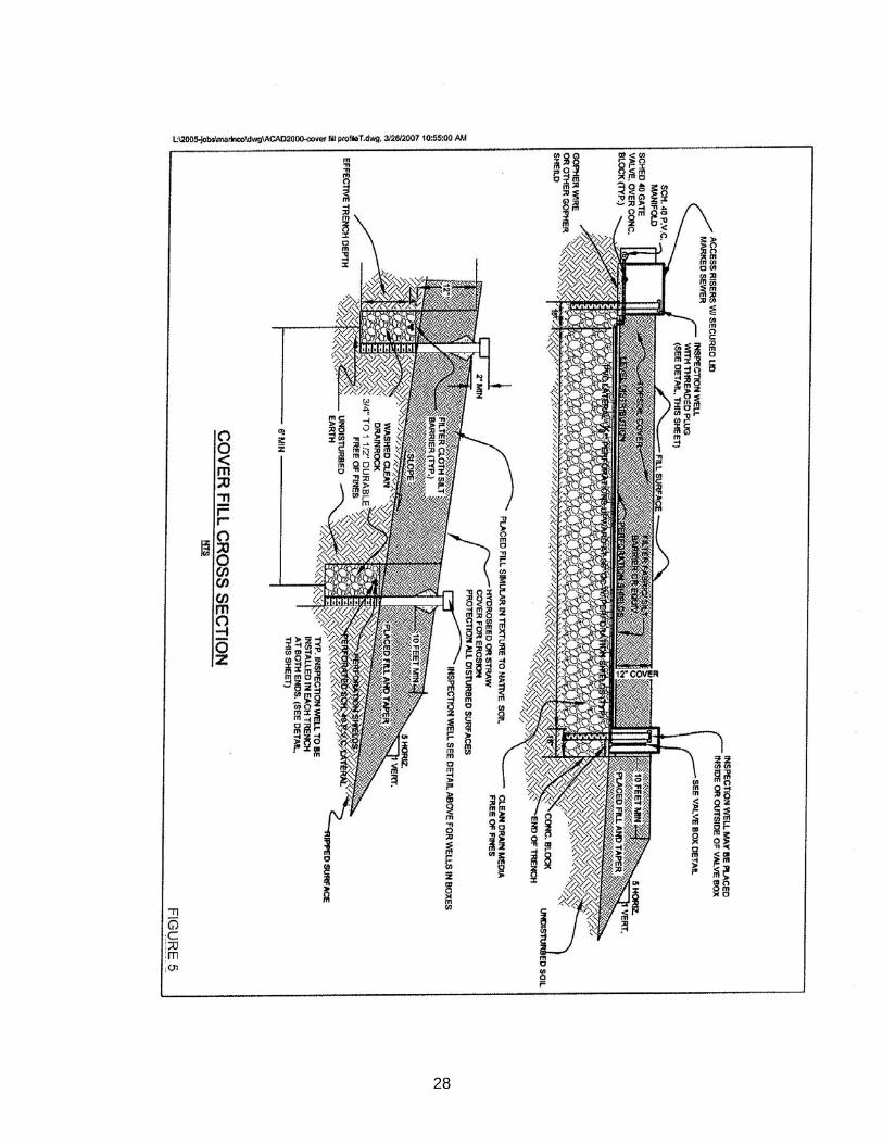
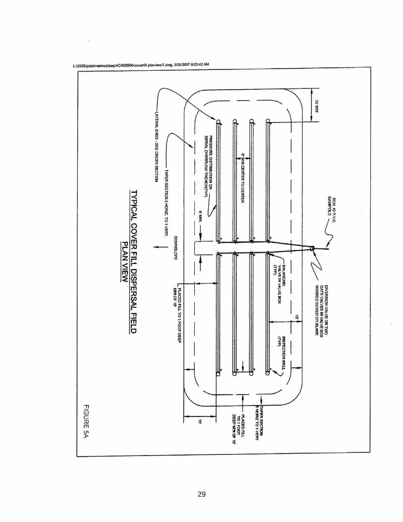
B. Modified Fill Systems. Where soil and/or groundwater conditions require shallow trench placement,
soil fill may be used to satisfy drainfield cover requirements. Typical cross-section details are shown in Figures 5 and 5A. Such fill systems shall comply with all site suitability and design criteria for standard systems as well as the following requirements
1. Ground Slope. Maximum allowable groundslope shall be 20%. Where the ground slope of the
leachfield exceeds 12 1/2%, or a pump or dosing siphon is included in the design, pressure distribution of effluent shall be employed.
2. Percolation Rate. The average percolation rate shall not be slower than 60 min./inch. For
pressurized systems the average percolation rate shall not be slower than 120 mpi
3. Drainfield Trenches. The drain media and perforated pipe sections shall be installed entirely within native soil and below existing grade. 4. Site Preparation. Prior to placement of fill material, all vegetation shall be removed and the
ground surface disced or plowed to permit good mixing of native soil and fill material. 5. Fill Material. The soil used for fill shall be similar in texture to the native soil. Sand, gravel or rock do not qualify as acceptable material for cover fill. The fill shall be placed prior to excavation of drainfield trenches. 6. Compaction. Fill shall be placed in layers of not more than eight (8) inches, and compacted to the same dry density as the native soil. Results of soil density tests may be required to be submitted to the Health Officer. Alternative compaction procedures may be allowed in accordance with recommendations and supporting technical data supplied by a registered civil engineer. 7. Coverage. The fill shall be continuous and constructed to a uniform depth of at least 12 inches
over all drainfield trenches. The fill shall extend a minimum distance of 15 feet in any direction from the center of any trench. If pressure distribution is employed, the toe of the fill should be tapered at not less than 5:1 ratio, beginning 15 feet from any drainfield trench as shown in Appendix A . In gravity-flow systems, extended coverage (20 feet) shall be provided.
C. Equal Pressure Dosed Trenches (EPDT)
1. EPDT are required under any of the following conditions:
a. Slopes greater than or equal to 30%
b. Standard trenches that will have less than the required minimum back fill cover for gravity flow trenches.
2. Siting criteria for EDPT shall comply with those specified in these regulations for standard
septic tank-leachfield systems.
20
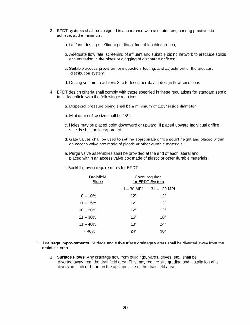
3. EPDT systems shall be designed in accordance with accepted engineering practices to achieve, at the minimum:
a. Uniform dosing of effluent per lineal foot of leaching trench;
b. Adequate flow rate, screening of effluent and suitable piping network to preclude solids accumulation in the pipes or clogging of discharge orifices;
c. Suitable access provision for inspection, testing, and adjustment of the pressure
distribution system; d. Dosing volume to achieve 3 to 5 doses per day at design flow conditions
4. EPDT design criteria shall comply with those specified in these regulations for standard septic tank- leachfield with the following exceptions:
a. Dispersal pressure piping shall be a minimum of 1.25” inside diameter. b. Minimum orifice size shall be 1/8”.
c. Holes may be placed point downward or upward. If placed upward Individual orifice shields shall be incorporated.
d. Gate valves shall be used to set the appropriate orifice squirt height and placed within an access valve box made of plastic or other durable materials. e. Purge valve assemblies shall be provided at the end of each lateral and
placed within an access valve box made of plastic or other durable materials.
f. Backfill (cover) requirements for EPDT
Drainfield Slope
Cover required for EPDT System
1 – 30 MP1 31 – 120 MPI
0 – 10% 12” 12”
11 – 15% 12” 12”
16 – 20% 12” 12”
21 – 30% 15” 18”
31 – 40% 18” 24”
> 40% 24” 30”
D. Drainage Improvements. Surface and sub-surface drainage waters shall be diverted away from the drainfield area.
1. Surface Flows. Any drainage flow from buildings, yards, drives, etc., shall be diverted away from the drainfield area. This may require site grading and installation of a diversion ditch or berm on the upslope side of the drainfield area.
21
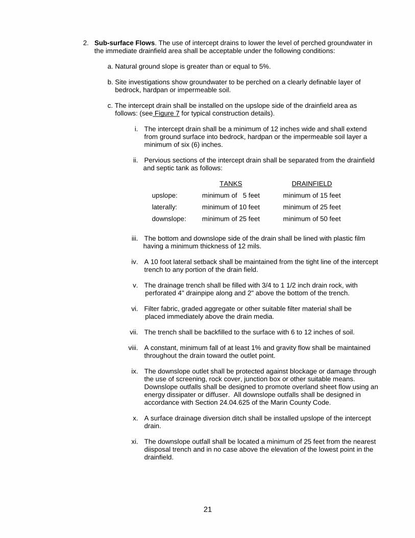
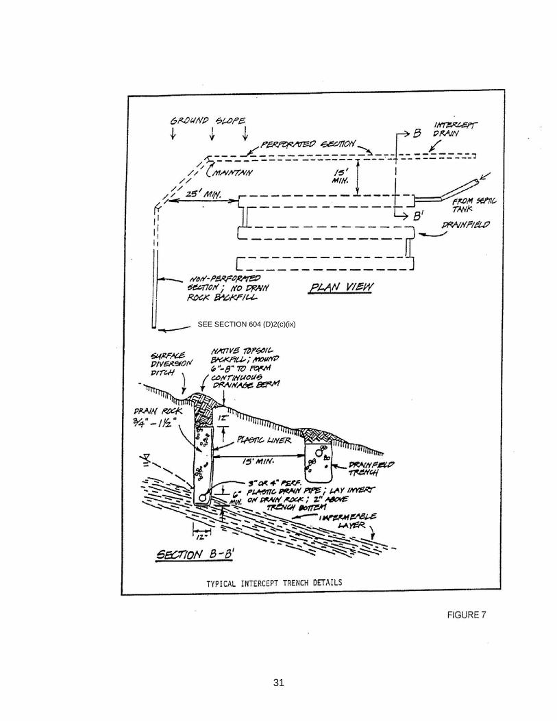
2. Sub-surface Flows. The use of intercept drains to lower the level of perched groundwater in the immediate drainfield area shall be acceptable under the following conditions: a. Natural ground slope is greater than or equal to 5%.
b. Site investigations show groundwater to be perched on a clearly definable layer of bedrock, hardpan or impermeable soil. c. The intercept drain shall be installed on the upslope side of the drainfield area as follows: (see Figure 7 for typical construction details).
i. The intercept drain shall be a minimum of 12 inches wide and shall extend from ground surface into bedrock, hardpan or the impermeable soil layer a minimum of six (6) inches.
ii. Pervious sections of the intercept drain shall be separated from the drainfield and septic tank as follows:
TANKS DRAINFIELD
upslope: minimum of 5 feet minimum of 15 feet
laterally: minimum of 10 feet minimum of 25 feet
downslope: minimum of 25 feet minimum of 50 feet
iii. The bottom and downslope side of the drain shall be lined with plastic film having a minimum thickness of 12 mils. iv. A 10 foot lateral setback shall be maintained from the tight line of the intercept
trench to any portion of the drain field. v. The drainage trench shall be filled with 3/4 to 1 1/2 inch drain rock, with perforated 4" drainpipe along and 2" above the bottom of the trench. vi. Filter fabric, graded aggregate or other suitable filter material shall be placed immediately above the drain media.
vii. The trench shall be backfilled to the surface with 6 to 12 inches of soil.
viii. A constant, minimum fall of at least 1% and gravity flow shall be maintained throughout the drain toward the outlet point.
ix. The downslope outlet shall be protected against blockage or damage through
the use of screening, rock cover, junction box or other suitable means. Downslope outfalls shall be designed to promote overland sheet flow using an energy dissipater or diffuser. All downslope outfalls shall be designed in accordance with Section 24.04.625 of the Marin County Code.
x. A surface drainage diversion ditch shall be installed upslope of the intercept
drain. xi. The downslope outfall shall be located a minimum of 25 feet from the nearest
diisposal trench and in no case above the elevation of the lowest point in the drainfield.
22
xii. Subsurface dispersal may be used as a basis for justifying a reduced separation distance between a drainfield and a retaining wall or building drain located downslope of the drainfield. Where this approach is used, the subsurface dispersal system shall be of a sufficient capacity for the expected amount of water collected in the building or wall drainage system.
xiii. Proposals that incorporate designs or materials that differ from the
requirements above may be accepted if certified by the design consultant and supported by technical documentation and independent testing
d. Engineering plans shall be provided to demonstrate compliance with the above provisions. Where the potential effectiveness of the intercept drain is not clear, the Health Officer may require such drain to be installed and demonstrated effective prior to issuance of an individual Sewage Disposal System.
700 INSTALLATION AND INSPECTION 701 General: Sewage disposal systems shall be installed in accordance with plans approved by the Health
Officer except for minor deviations. Changes in sewage disposal plans made during system installation must be approved by the Health Officer and documented in an as-built drawing. The Department may require a homeowner who installs his or her own system to retain the services of a qualified special inspector. The special inspector shall observe, inspect and report on critical aspects of the system installation.
702 Tanks:
A. All tanks including septic tanks, grease interceptor tanks, processing tanks and sumps shall be installed level on a firm bedding of compacted soil, sand or gravel in accordance with the manufacturer’s specifications.
B. All tanks shall be sealed against leaks and demonstrated to be watertight by field testing conducted as follows during the installation of the system: Fill tanks with water two inches into riser connections and mark water level. No drop in the water level should be observed during field inspection by County staff. If water level drops, the tank will need to be resealed and retested.
C. Design details and calculations for in-ground grease interceptors shall be submitted to EHS for review
and approval. The interceptor volume shall be based upon the peak wastewater flow from the facility.
703 Drain fields:
A. Trenches should be constructed when the soil is dry to minimize unnecessary soil compaction and smearing of trench sidewalls. B. Smearing of the infiltrative surfaces (trench bottom and sidewalls) during construction shall be Corrected by scarifying the infiltrative surfaces after excavation is complete. C. Surface runoff shall be prevented from entering open trenches during construction to minimize siltation of the trench bottom area. D. Backfill shall be placed so as to maximize surface runoff and not crush piping or chambers. E. Erosion protection in the drainfield area shall be required upon completion of installation.
23
704 Inspections: A. All installations shall be inspected by the Health Officer before they are considered complete.
B. The Health Officer shall be notified at least two business days prior to installation of the system to allow inspection of trenches, septic tank and related features. C. Sewage disposal systems requiring pump installations or other electrical features shall be inspected by the County Building Inspection Division. D. In addition to items 1, 2 and 3 above, alternative systems shall require inspection, testing and certification by the engineer of record. Such inspection work shall be conducted in accordance with recommended procedures proposed by the engineer and approved by the Health Officer. (See Section 800 Alternative Systems.)
800 ALTERNATIVE SYSTEMS (see separate package) 900 WAIVER OF REGULATIONS 901 General: Waiver of any of the regulations contained herein may be granted by the Health Officer when,
because of special circumstances applicable to the location, soil characteristics, or surroundings, the strict application of these regulations would deprive such property of privileges enjoyed by other properties in the vicinity, provided, however, that no waiver shall be granted if reduction of requirements would present a threat to water quality or public health. Waiver requests shall be processed in accordance with the provisions contained in Marin County Code Section 18.07.105
902 Application: Applications for waiver(s) shall be made in writing on a form prescribed by the Health Officer,
and shall be accompanied by appropriate technical information or report(s) supporting the waiver request. 903 Review and Determination: Upon receipt of the application and supporting information, the Health Officer
shall review the request and conduct an investigation to determine whether a waiver should be granted under the provisions of Section 901 above. The Regional Water Quality Control Board shall be notified of the waiver application and the Health Officer's investigation. After conclusion of the investigation, the Health Officer shall prepare a written order granting or denying the waiver, and shall include in such written order specific findings of fact and reasons for its granting or denial.
904 Nonconforming Lots: This section shall not be construed to allow the creation of new substandard or
nonconforming lots or parcels, except with the explicit approval of the Board of Supervisors, and upon a showing of good cause and finding that such variance will not be injurious to the public health.
905 Geographical Area Waivers: From time to time, the Health Officer may consider the issuance of waivers
to specific provisions of these regulations for general geographical areas of the county. Such geographical area waivers may be considered in response to application(s) by individuals or solely upon the initiative of the Health Officer. Adequate technical justification must be presented in support of such waivers, and will be subject to review and concurrence by the San Francisco Bay Regional Water Quality Control Board. Geographical area waivers adopted as provided here will be incorporated into these regulations.
24
25
26
27
28
29
30
31
SEE SECTION 604 (D)2(c)(ix)
32
33
34
35