Embed Size (px)
Citation preview
REGISTERS AND REGISTER
TRANSFERS
Basic Symbols
1
EKT221 - DIGITAL ELECTRONIC II
Outlines
Register Transfer Language
Type of Registers
Basic Symbols
Register Transfer
Arithmetic Microoperations
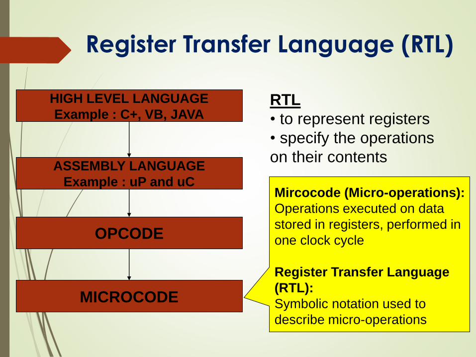
HIGH LEVEL LANGUAGE
Example : C+, VB, JAVA
ASSEMBLY LANGUAGE
Example : uP and uC
OPCODE
MICROCODE
Mircocode (Micro-operations):
Operations executed on data
stored in registers, performed in
one clock cycle
Register Transfer Language
(RTL):
Symbolic notation used to
describe micro-operations
Register Transfer Language (RTL)
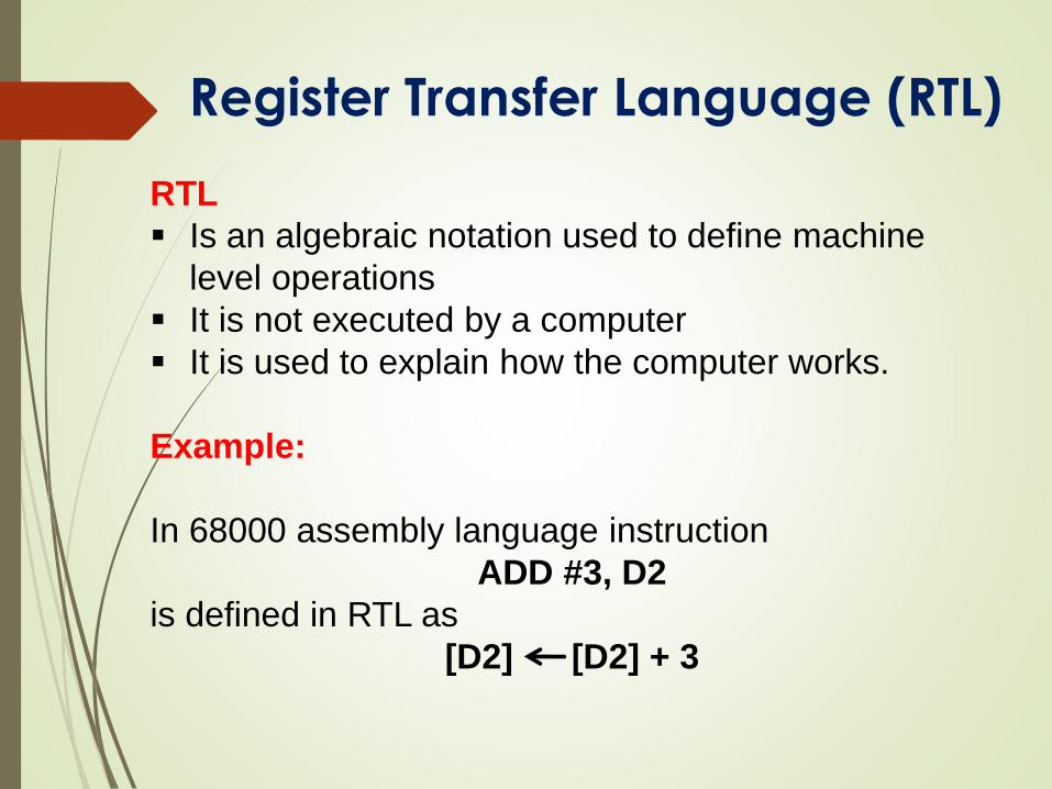
RTL
• to represent registers
• specify the operations
on their contents
RTL
Is an algebraic notation used to define machine
level operations
It is not executed by a computer
It is used to explain how the computer works.
Example:
In 68000 assembly language instruction
ADD #3, D2
is defined in RTL as
[D2] [D2] + 3
Register Transfer Language (RTL)
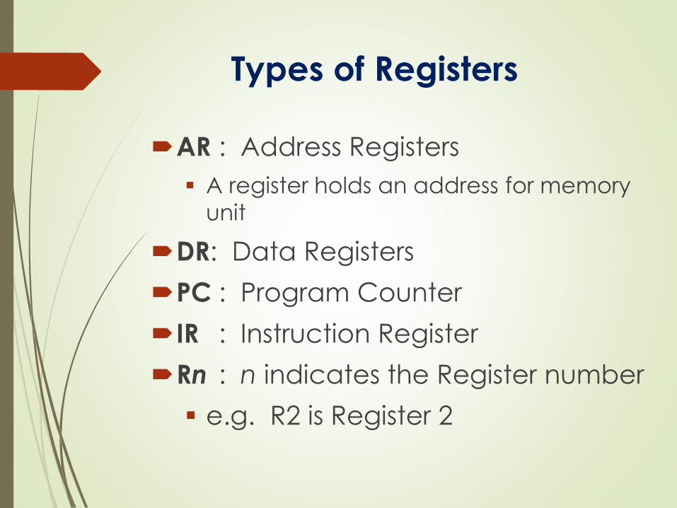
Types of Registers
AR : Address Registers
A register holds an address for memory
unit
DR: Data Registers
PC : Program Counter
IR : Instruction Register
Rn : n indicates the Register number
e.g. R2 is Register 2
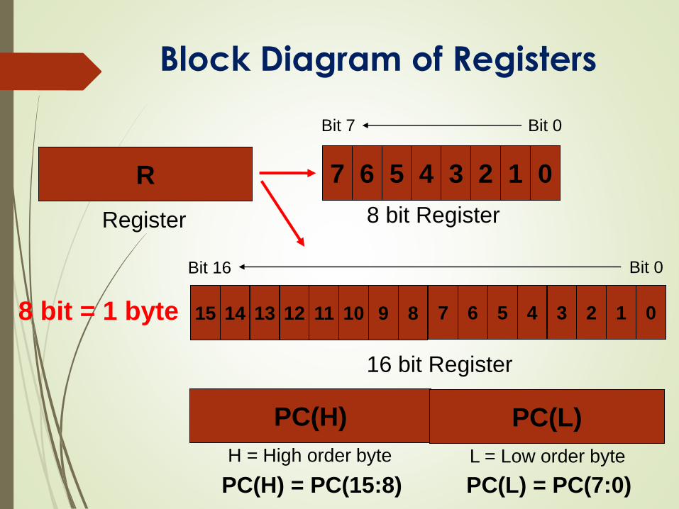
Block Diagram of Registers
R
PC(H)
Register
16 bit Register
7
8 bit Register
6 5 4 3 2 1 0
Bit 7 Bit 0
15 14 13 12 11 10 9 8 7 6 5 4 3 2 1 0
Bit 16 Bit 0
PC(L)
8 bit = 1 byte
H = High order byte L = Low order byte
PC(H) = PC(15:8) PC(L) = PC(7:0)
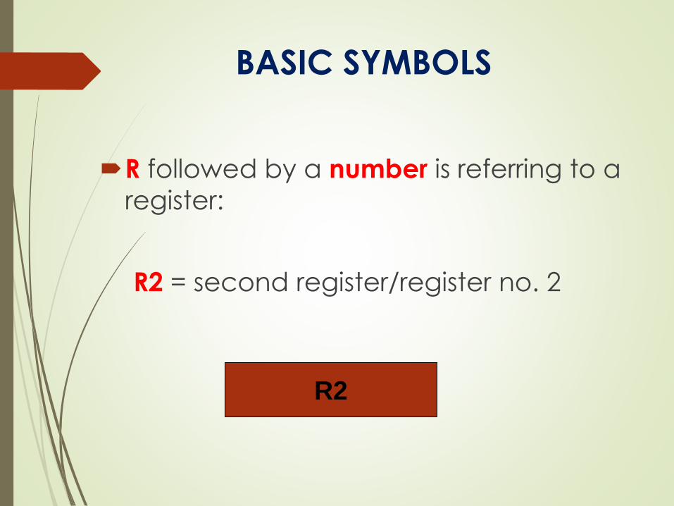
BASIC SYMBOLS
R followed by a number is referring to a
register:
R2 = second register/register no. 2
R2
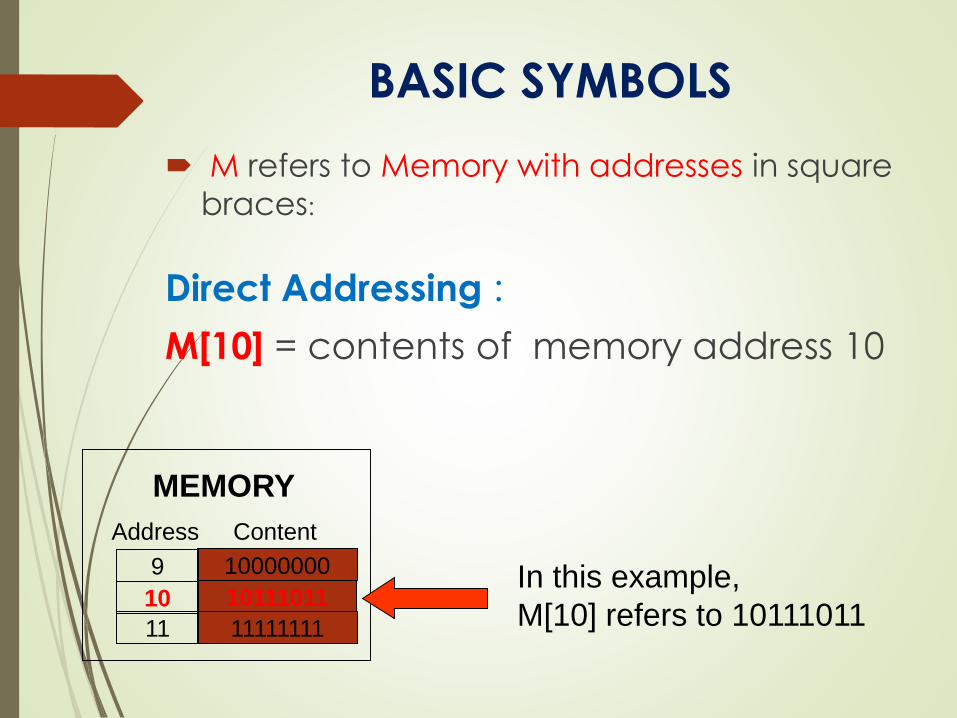
BASIC SYMBOLS
M refers to Memory with addresses in square
braces:
Direct Addressing :
M[10] = contents of memory address 10
In this example,
M[10] refers to 10111011
10000000
10111011
11111111
9
10
11
Address Content
MEMORY
BASIC SYMBOLS
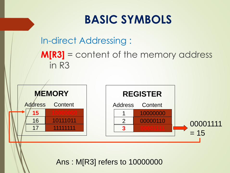
In-direct Addressing :
M[R3] = content of the memory address
in R3
10000000
10111011
11111111
15
16
17
Address Content
MEMORY
10000000
00000110
00001111
1
2
3
Address Content
REGISTER
00001111
= 15
Ans : M[R3] refers to 10000000
BASIC SYMBOLS
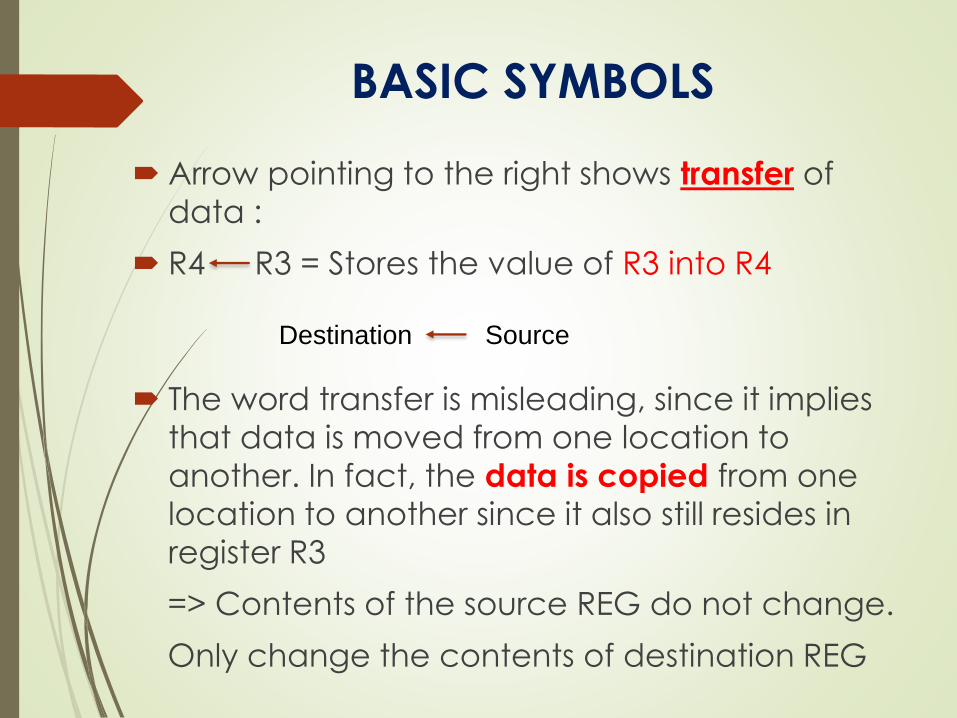
Arrow pointing to the right shows transfer of
data :
R4 R3 = Stores the value of R3 into R4
The word transfer is misleading, since it implies
that data is moved from one location to
another. In fact, the data is copied from one
location to another since it also still resides in
register R3
=> Contents of the source REG do not change.
Only change the contents of destination REG
Destination Source
BASIC SYMBOLS
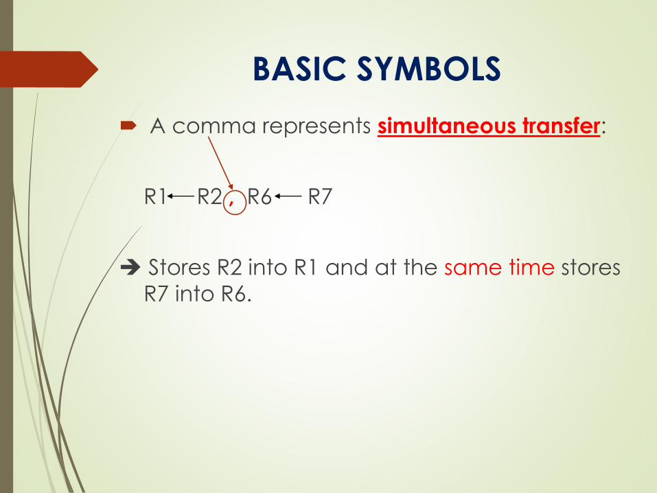
A comma represents simultaneous transfer:
R1 R2 , R6 R7
Stores R2 into R1 and at the same time stores
R7 into R6.
BASIC SYMBOLS
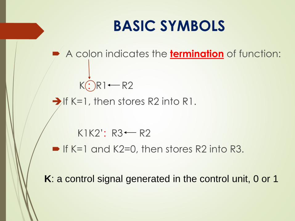
A colon indicates the termination of function:
K : R1 R2
If K=1, then stores R2 into R1.
K1K2’: R3 R2
If K=1 and K2=0, then stores R2 into R3.
K: a control signal generated in the control unit, 0 or 1
BASIC SYMBOLS
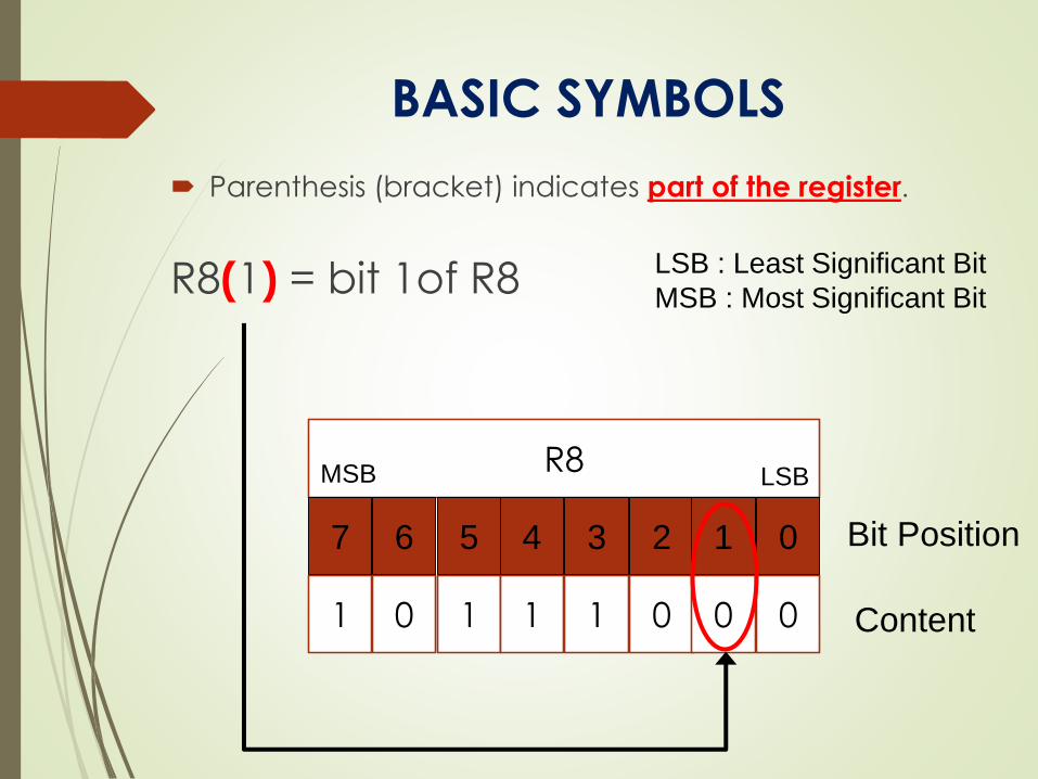
Parenthesis (bracket) indicates part of the register.
R8(1) = bit 1of R8
R8
7 6 5 34 2 1 0
1 0 1 11 0 0 0
Bit Position
Content
MSB LSB
LSB : Least Significant Bit
MSB : Most Significant Bit
BASIC SYMBOLS
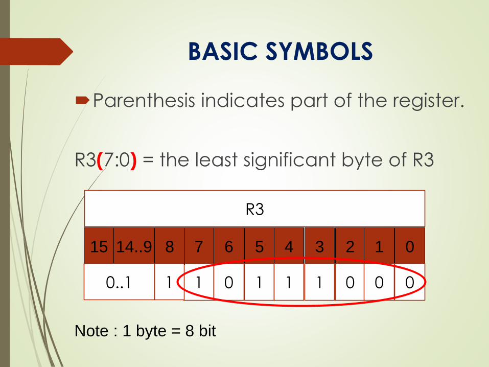
Parenthesis indicates part of the register.
R3(7:0) = the least significant byte of R3
Note : 1 byte = 8 bit
R3
7 6 5 34 2 1 0
1 0 1 11 0 0 0
14..915 8
10..1
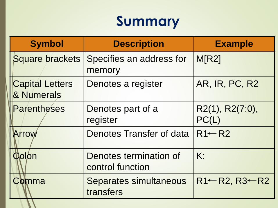
Summary
Symbol Description Example
Square brackets Specifies an address for
memory
M[R2]
Capital Letters
& Numerals
Denotes a register AR, IR, PC, R2
Parentheses Denotes part of a
register
R2(1), R2(7:0),
PC(L)
Arrow Denotes Transfer of data R1 R2
Colon Denotes termination of
control function
K:
Comma Separates simultaneous
transfers
R1 R2, R3 R2
ARITHMETIC MICROOPERATIONS
The basic arithmetic microoperations areAddition
Subtraction
Increment
Decrement
The additional arithmetic microoperationsareAdd with carry
Subtract with borrow
Transfer/Load
etc. …
Arithmetic Microoperations
MATHEMATICAL AND
LOGICAL SYMBOLS
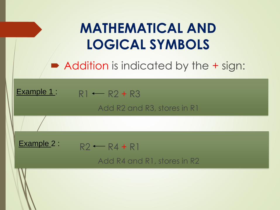
Addition is indicated by the + sign:
R1 R2 + R3
Add R2 and R3, stores in R1
R2 R4 + R1
Add R4 and R1, stores in R2
Example 1 :
Example 2 :
MATHEMATICAL AND
LOGICAL SYMBOLS
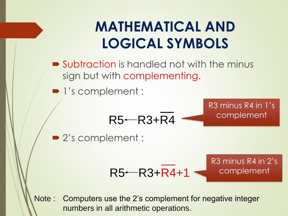
Subtraction is handled not with the minus
sign but with complementing.
1’s complement :
2’s complement :
R5 R3+R4
R5 R3+R4+1
R3 minus R4 in 1’s
complement
R3 minus R4 in 2’s
complement
Note : Computers use the 2’s complement for negative integer
numbers in all arithmetic operations.
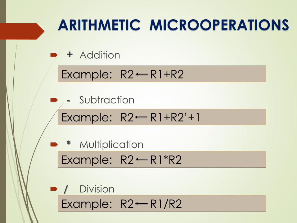
+ Addition
- Subtraction
* Multiplication
/ Division
Example: R2 R1+R2
Example: R2 R1+R2’+1
Example: R2 R1*R2
Example: R2 R1/R2
ARITHMETIC MICROOPERATIONS
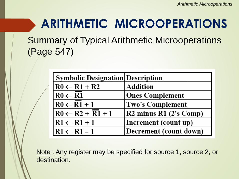
Summary of Typical Arithmetic Microoperations
(Page 547)
Arithmetic Microoperations
ARITHMETIC MICROOPERATIONS
Note : Any register may be specified for source 1, source 2, or
destination.
MICROOPERATIONS
Microoperations - The operations performed
on data stored in registers or in memory.
The functions built into registers are
examples of microoperations
Shift
Load
Clear
Increment
…
MICROOPERATIONS
The microoperations most often encountered in digital systems are of four types:
Register transfer microoperations
Transfer binary data from one REG to another
Arithmetic microoperations
Perform arithmetic on data in REG
Logic microoperations
Perform bit manipulation on data in REG
Shift microoperations
Shift data in REG
REGISTER TRANSFER
Copying the contents of one register to
another is a register transfer.
A register transfer is indicated as
R2 R1 In this case the contents of register R1 are copied
(loaded) into register R2.
A simultaneous transfer of all bits from the source R1
to the destination register R2, during one clock pulse.
Note that this is a non-destructive; i.e. the contents of
R1 are not altered by copying (loading) them to R2
REGISTER TRANSFER
A register transfer such as
R3 R5Implies that the digital system has
the data lines from the source register (R5) to
the destination register (R3)
Parallel load in the destination register (R3)
All bits are loaded simultaneously on clock pulse
(same source)
Control lines to perform the action
Control the transfer or clock cycles
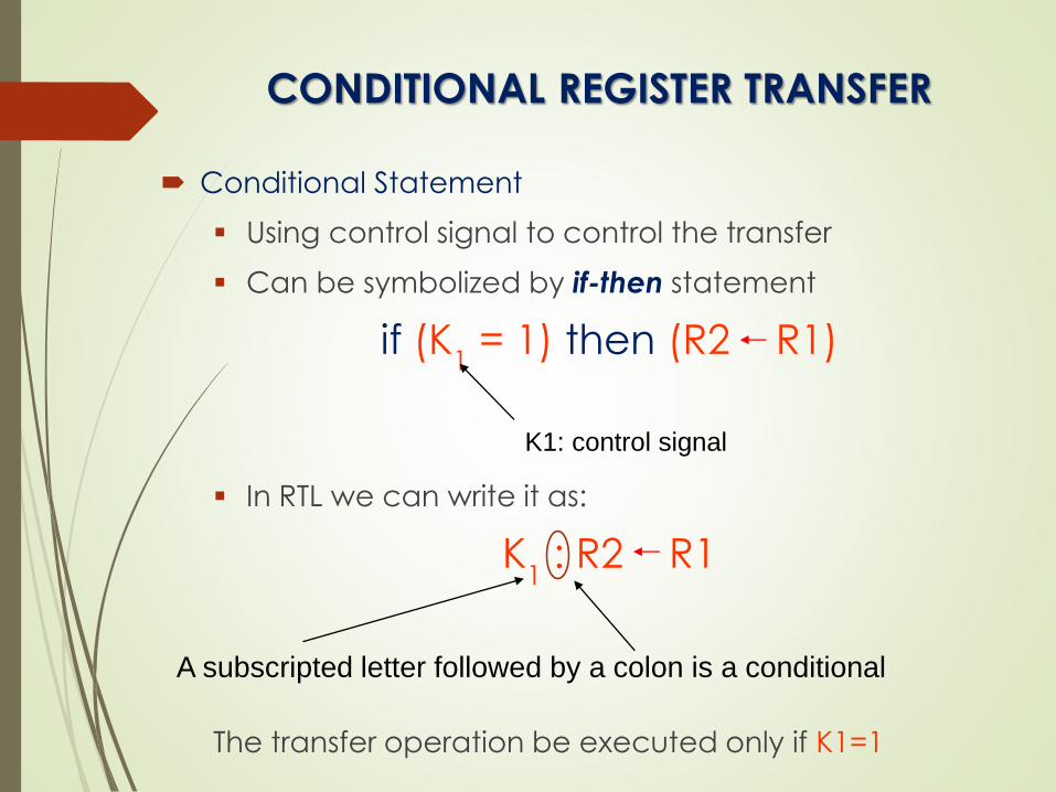
CONDITIONAL REGISTER TRANSFER
Conditional Statement
Using control signal to control the transfer
Can be symbolized by if-then statement
if (K1
= 1) then (R2 R1)
In RTL we can write it as:
K1
: R2 R1
The transfer operation be executed only if K1=1
A subscripted letter followed by a colon is a conditional
K1: control signal
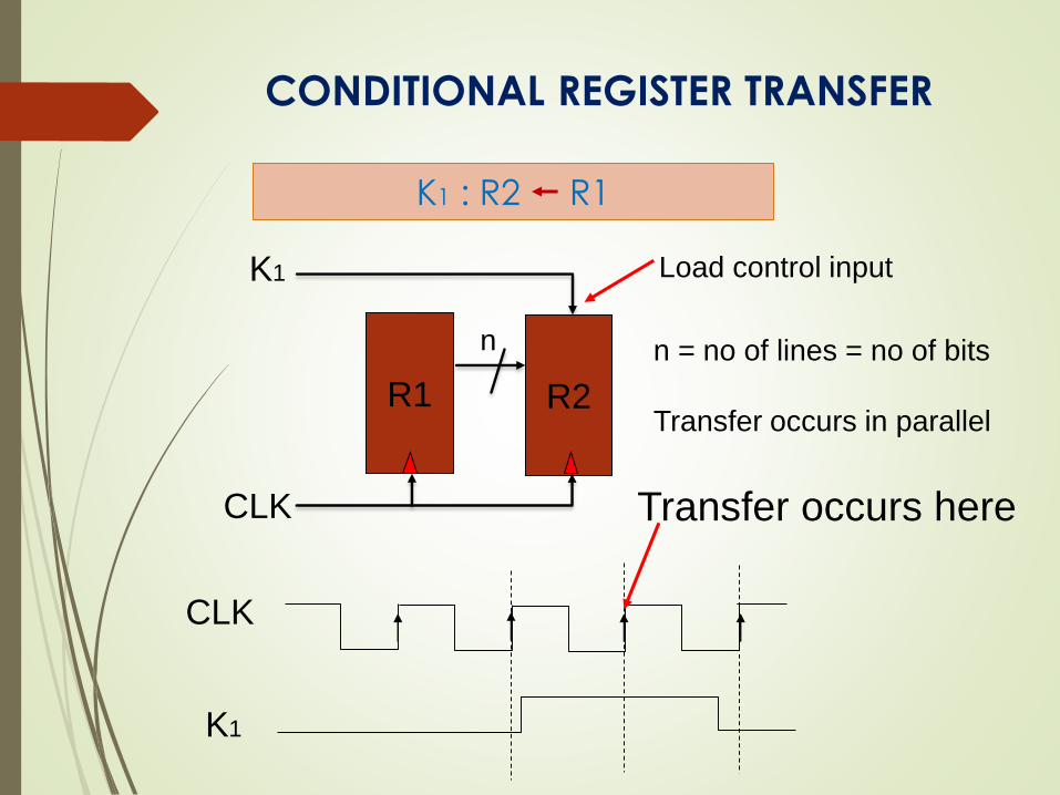
CONDITIONAL REGISTER TRANSFER
R2R1
K1
CLK
n
K1
CLK
Transfer occurs here
n = no of lines = no of bits
Transfer occurs in parallel
K1 : R2 R1
Load control input
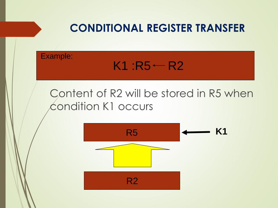
K1 :R5 R2
CONDITIONAL REGISTER TRANSFER
Content of R2 will be stored in R5 when
condition K1 occurs
R5
R2
K1
Example:
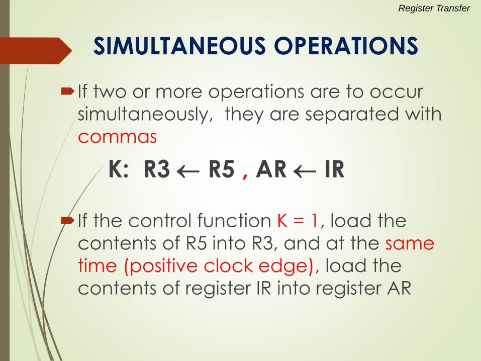
SIMULTANEOUS OPERATIONS
If two or more operations are to occur
simultaneously, they are separated with
commas
K: R3 R5 , AR IR
If the control function K = 1, load the
contents of R5 into R3, and at the same
time (positive clock edge), load the
contents of register IR into register AR
Register Transfer
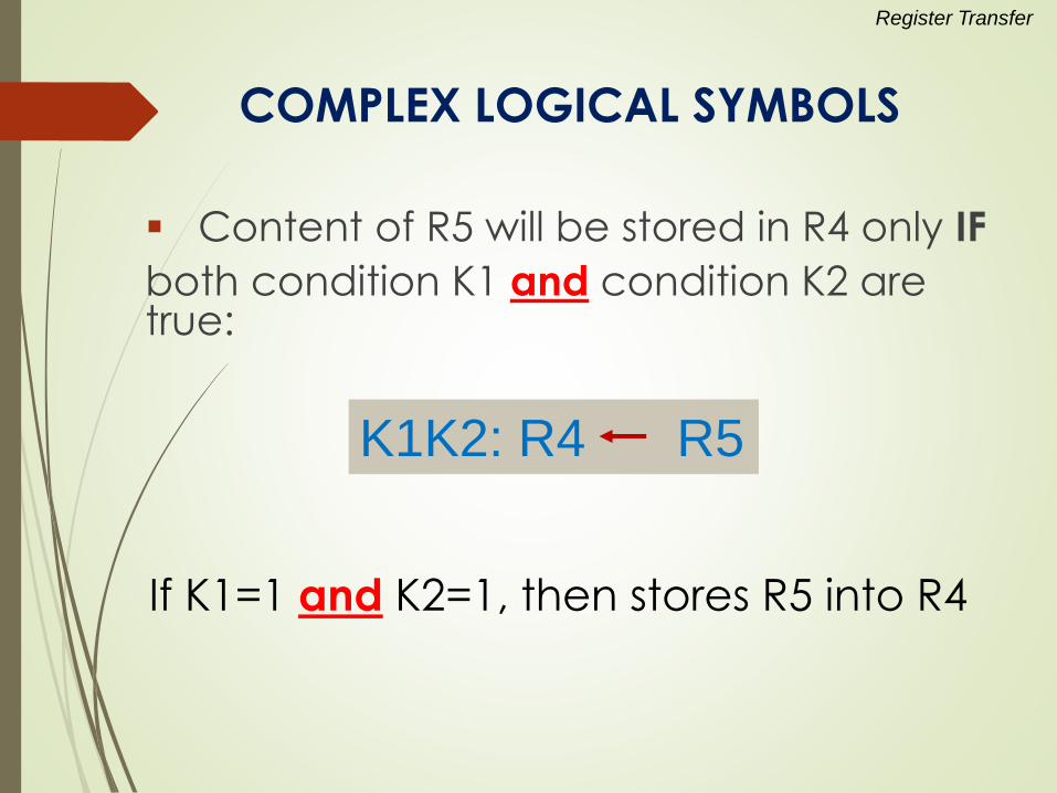
COMPLEX LOGICAL SYMBOLS
Content of R5 will be stored in R4 only IF
both condition K1 and condition K2 are true:
K1K2: R4 R5
Register Transfer
If K1=1 and K2=1, then stores R5 into R4
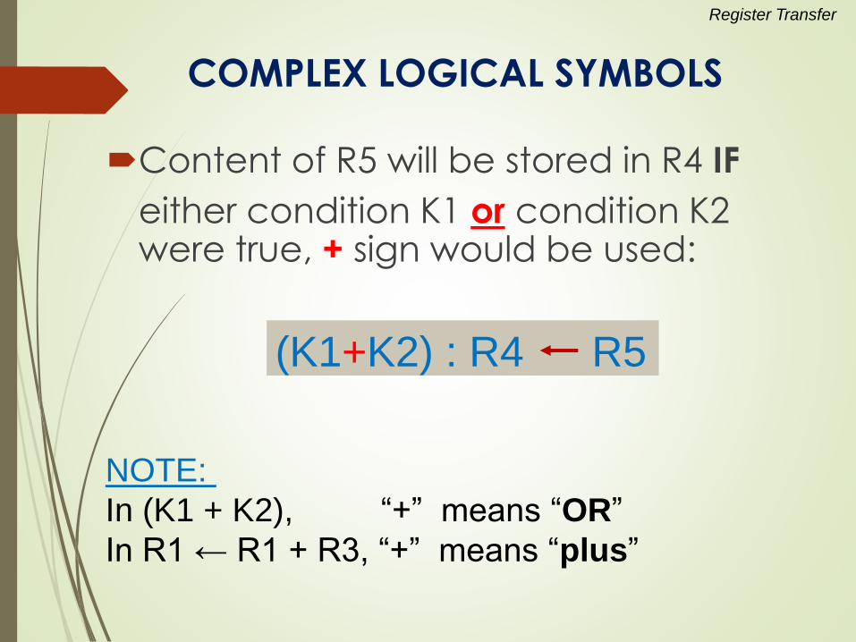
COMPLEX LOGICAL SYMBOLS
Content of R5 will be stored in R4 IF
either condition K1 or condition K2 were true, + sign would be used:
(K1+K2) : R4 R5
NOTE:
In (K1 + K2), “+” means “OR”
In R1 ← R1 + R3, “+” means “plus”
Register Transfer
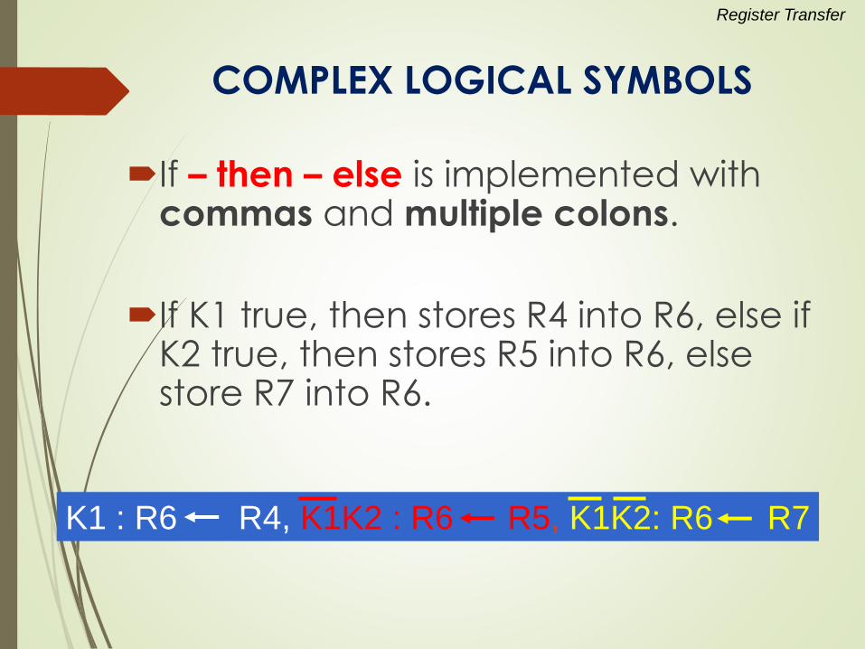
COMPLEX LOGICAL SYMBOLS
If – then – else is implemented with commas and multiple colons.
If K1 true, then stores R4 into R6, else if K2 true, then stores R5 into R6, else store R7 into R6.
K1 : R6 R4, K1K2 : R6 R5, K1K2: R6 R7
Register Transfer

Thank you