Embed Size (px)
Citation preview

W-2134B-16 AUGUST 22, 2016 PAGE 1 OF 8 ADDENDUM NO. 6
Regional Municipality of Halton APPLEBY ZONE 3 BOOSTER PUMPING STATION
IN THE CITY OF BURLINGTON CONTRACT W-2134B-16
ADDENDUM NO. 6
Issue Date: Monday, August 22, 2016
This Addendum No. 6 forms part of the Plans and Contract Documents for the above noted contract and shall be read in conjunction therewith. This Addendum No. 6 shall take precedence over all requirements of the original plans and contract documents issued previously. The Tenderer must acknowledge receipt of this Addendum No. 6 on page 3 of the Form of Tender.
NO. OF ADDENDUM PAGES: 8 NO. OF REVISED CONTRACT DOCUMENT PAGES: 1 NO. OF DRAWINGS (SKETCHES): 10 NO. OF NEW SPECIFICATION PAGES: 5 TOTAL NO. OF PAGES:
24
ISSUE 1: HVAC QUESTIONS
1) Is there a spec on the Air Handler Unit?
Response: Please refer to the mechanical schedule on Drawing M-402.
2) Is there an alternate to Lennox Listed?
Response: Please refer to the Air Conditioning System mechanical schedule on Drawing M-402. Per the Region of Halton’s Pre-Qualified Equipment List, May 2016 approved products for the air conditioning and heating systems are Carrier Ltd., Trane Canada Ltd., and Lennox Industries.
3) Outside air intake ductwork; specification on drawing M – 101 calls for 1” thick fiberglass insulation. Note 3 on drawing M – 201 calls for 2” thick insulation. Which is correct?
4) Note 3 also say’s to insulate ductwork up to the equipment connected yet the drawing shows the duct only partially insulated back from the wall. Which is correct?
5) Exhaust ductwork; specification on drawing M – 101 calls for 1” thick fiberglass insulation. Note 3 on drawing M – 201 calls for 2” thick insulation. Which is correct?

W-2134B-16 AUGUST 22, 2016 PAGE 2 OF 8 ADDENDUM NO. 6
6) Specification on drawing M – 101 calls for insulation on the last 5 LF on exhaust ductwork. Note 3 on drawing M – 201 calls for insulation on the last 10 LF of ductwork. Which is correct?
Response: Insulation for outside air intake ductwork to be 1". Duct insulation to be 3000 mm upstream of the exterior wall penetration. Insulation for exhaust ductwork to be 1". Insulation to be on the last 10 LF of the exhaust ductwork.
7) Mechanical – Drawing M-101 Note 7.4 states to insulate all new rigid supply air duct. However the supply air shown on drawing M-201 below the walkway is exposed in the area that is being served. There are also dashed lines immediately after the air intake louvre. There are no dashed lines shown on the ductwork shortly before and after the supply fan. Will external insulation be required where the supply air is exposed in the area that it serves or only where indicated with dashed line on outside of drawn intake air duct?
8) Mechanical – Drawing M-101 Note 7.5 states that all exhaust and air intake are to be insulated with 1” thick insulation 5 feet back from exterior penetrations. However general note 3 on drawing M-201 states that exhaust is to be insulated with 50 mm thick insulation 3000mm from exterior penetration and outside air is to be insulated up to the equipment connected. Please clarify which note to follow.
Response: All duct insulation to be 3000 mm downstream of the exterior wall penetration / air handling unit. All duct insulation to be 25mm.
9) RE: Insulation Specification on Drawing No: M – 101, Ductwork insulation section’s 7.4 & 7.5. The insulation is spec’d as 1” x 3 lb/cuft foil faced rigid board OR 1” x 3 lb/cuft foil faced flexible with no distinction as too where. Is the intent to use rigid board on exposed ductwork and flexible on the concealed ductwork or rigid board on all rectangular ductwork and flexible insulation on all round?
Response: The intent is to use rigid board where ductwork is exposed, and flexible insulation on all concealed ductwork.
10) The requested density for the 1” foil faced flexible duct insulation is 3 lb/cuft. This product is not available in this density. Typically ¾ lb/cuft density is used on concealed and round ductwork. Would 1 ½” thick x ¾ lb/cuft density be acceptable on the concealed and/or round ductwork?
Response: 1 ½” thick x ¾ lb/cu ft density will be acceptable for use on the concealed and/or round ductwork.
ISSUE 2: COUPLINGS ON SS PIPING
Please clarify the requirements for grooved type couplings on stainless steel process piping. The details provided in Section 15050-2.5 are somewhat generic. Specifically, are the couplings to be epoxy-coated, galvanized, stainless steel or either of the three? A make and model would also be helpful.
Response: See Response to Addendum No.5 Issue 15.

W-2134B-16 AUGUST 22, 2016 PAGE 3 OF 8 ADDENDUM NO. 6
ISSUE 3: CONSTRUCTION STAGING
Refer to SGC.4 - Staging of the Work. Please advise what Pumping Station construction activities can be started before receiving the building permit?
Response: With full Site Plan Approval, the following works can begin on site: mobilization, clearing and grubbing and site fencing. Following acquisition of the full Site Plan Approval, the Region will obtain a Shoring and Excavation Permit and a Foundation Permit to allow excavation and foundation works to proceed.
ISSUE 4: STEEL LINTELS
There is a steel lintel schedule for block walls on drawing S-500 detail T16; however, schedule for the 90mm veneer brick cannot be found. Architectural detail 5 on a drawing A114 refer to the structural, but structural detail is giving info only for the block wall.
Response: Lintels are to be galvanized steel angles L90 x 90 x 10 mm.
ISSUE 5: ELECTRICAL QUESTIONS
1) It is not clear how information from the RTDs will be monitored.
2) Addendum #3 – Issue 7 – There is a mention of the service entrance disconnect to be 15A that should be 1000A or 800A. Are we to use the 15A until awarded the job?
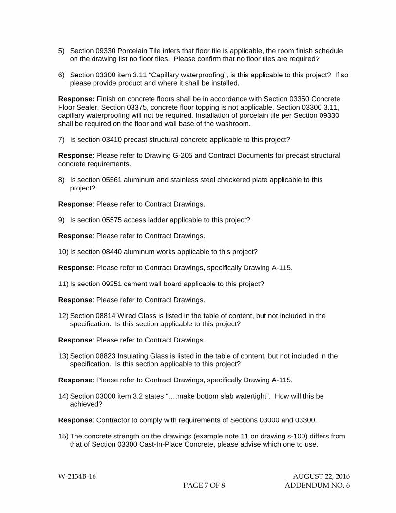
Response: DELETE Drawings E-201, E-202, and E-203 and REPLACE WITH revised Drawings E-201, E-202, and E-203 attached. DELETE Drawing E-103 and REPLACE WITH revised Drawing E-103 attached.
3) Addendum #3 – Issue 8 – Dwg. E102, the cables from the transformer are 12 – 1C 350 RWU90 + 1 gnd teck. Does this mean 12 – 350 Rwu90 cables (are only cables) & only the gnd is the teck? Drawing E301 shows the duct bank having only 8 – 3” conduits, there should be 12 conduits and 3” is not large enough. This is also the same for the cables to the generator.
Response: Please see response to Addendum No. 5 Issue 16.
4) Drawing E-101 indicates that the 1000kVA Transformer is to be located where the existing 500kVA transformer is currently located. Drawing G-101 indicates that the transformer is in a different location. Which one is correct?
Response: Drawing G-101 is correct. The intent of the description on E-101 is that the existing transformer be replaced with a 1000kVA transformer at the other transformer location near the east property line.
ISSUE 6: IGU GLASS
IGU glass spec and drawing are in conflict. spec 6mm tem+13warm+6mm ag 50 drawing 6mm tem lam +10warm+6mm lam ag 50 drawing price almost two time specs.
Response: IGU glass per Architectural Drawings is correct.

W-2134B-16 AUGUST 22, 2016 PAGE 4 OF 8 ADDENDUM NO. 6
ISSUE 7: INSULATION FOR SANITARY LATERAL TRENCH
What is the alternate method of insulation could be used for the sanitary trench? In the same context is it possible to provide minimum cover by grading the ditch accordingly to minimise the amount of insulation required?
Response: Provide insulated PVC pipe for the sanitary lateral as indicated in Contract Drawings G-221 to G-223.
ISSUE 8: EXISTING VALVE HOUSE AS-BUILTS
As per section 13300 scope of work, we have to replace all existing power and control wiring of instruments in existing valve house. Can we have as-built drawing showing locations of instruments in reservoir valve house so we can allow for new conduit and wiring as indicated in scope of work.
Response: Please see attached As-Built Drawings for existing valve house.
Note in regard to the as-built drawings: The Regional Municipality of Halton, its employees, officers and agents are not responsible for any errors, omissions or inaccuracies whether due to their negligence or otherwise. All information in the drawings should be verified.
ISSUE 9: ROOFING
Refer to indicated single ply fully adhered roofing system as per drawing A-105, no specification identified, please confirm.
Response: Please refer to Specification Section 07610 "Pre-Finished Metal Roofing".
ISSUE 10: BEDDING MATERIAL
Type and depth of granular material is not specified in the drawing.
Response: See response to Addendum No.5 Issue 8, Questions 2, 3, and 4.
ISSUE 11: GENERATOR SOUND ATTENUATION
“Could you please ask for clarification on addendum # 3 Issue 18?
Generator Enclosure sound levels.
Please review the sound calculations provided? The general rule of thumb for sound reduction is sound decreases by 6dba every time you double the distance (ex; 78dba @ 7m once doubled to 14m will provide 72dba sound pressure level) therefore the calculation provided based on 78dba@ 7m would result in sound level at property line of approximately 70dba.
My calculations estimate required sound level at 7m from generator should be 60dba to meet 50dba a property line (18m).”

W-2134B-16 AUGUST 22, 2016 PAGE 5 OF 8 ADDENDUM NO. 6
Response: Sound attenuation for the standby diesel generator is to be designed, supplied and installed to meet all criteria indicated in Addendum No.3. The maximum allowable sound level at the property limit is 50 dBA.
ISSUE 12: LOCAL CONTROL PANEL FABRICATION
Please advise whether the local control panel (Tag PMSCP05 relating to Section 11221, I-103) needs to be fabricated in a CSA approved shop per Section 16641 or is it acceptable for the local control panel to be fabricated according to CSA standards and come with CSA field evaluation stamp ?
Response: It is acceptable for the local control panel to be fabricated according to CSA standards and to be provided with a CSA field evaluation stamp.
ISSUE 13: INSTRUMENTATION
1) Instruments Summary List indicates that ALRCST1LI, and Ultrasonic Level Sensor are existing; however, these items are in bold on drawing I-202. Please clarify.
Response: ALRCST1LI and Ultrasonic Level Sensor are to be replaced per Drawing I-202.
2) Drawing I-400 indicates a reservoir building. Please provide a drawing and location of the reservoir building.
Response: The facility referred to as the Reservoir Building in the instrumentation drawings is the same facility as the existing Valve House per Drawing E-101.
3) Are computers indicated in drawing I-400 existing, or to be supplied by contractor? Please provide specifications on workstations, software, and thin client, if required. Which division will supply these?
Response: Computer workstations indicated on Drawing I-400 shall be supplied by the Region per Note 2 on Drawing I-400.
ISSUE 14: CHEMICAL SYSTEM
Is Chemical pump control panel, ALRPMSCP05, to be supplied by named chemical system supplier? Division 11 does not specify any pump panels for the chemical feed system.
Response: Chemical pump control panel, ALRPMSCP05, is to be supplied by named chemical system supplier.
ISSUE 15: MESH CONFIGURATION
Spec section 6610, 2.4.5 reads "Mesh Configuration: 25.4 mm x 50 mm with a tolerance of plus or minus 1.5 mm mesh centreline to centreline." This is a high load capacity grating for vehicular traffic; is this correct or should this be the regular square mesh grating?
Response: Mesh configuration to comply with Section 06610 2.4.5.

W-2134B-16 AUGUST 22, 2016 PAGE 6 OF 8 ADDENDUM NO. 6
ISSUE 16: SANITARY LATERAL
1) Reference: Sanitary Lateral Section 02531 Clause 2.4 Miscellaneous Appurtenances- Is it applicable to the Sanitary Laterals?
Response: Appurtenances as specified in Section 02531 are applicable for both the sanitary lateral and sewer.
2) Do we have to provide tracer wires for the Sanitary Lateral?
Response: Tracer wire is required for the sanitary lateral and sewer as specified in Section 02531.
3) What is the testing requirements for the Sanitary Laterals
Response: The testing and commissioning of the sanitary lateral and sewer shall comply with the requirements specified in Section 02531 and applicable Division 1 specifications.
ISSUE 17: ARCHITECTURAL QUESTIONS
1) Refer to drawing A-106 and A-108. Please provide a specification for the glass fibre reinforced concrete arches and prefinished cementitious panels.
Response: Glass fibre reinforced concrete arches and prefinished cementitious panels to be standard supply as indicated on Architectural Drawings and attached Section 04400 Glass Fibre Reinforced Concrete Arches and Capitals.
2) The brick specification in Division 4 notes a Metric Modular unit. The brick noted for Wall Type W1 drawing note Sheet A-100 requirements is a Jumbo Brick.
Response: DELETE Section 04200 2.2.2
and REPLACE WITH revised Section 04200 2.2.2:
"Brick size – Metric Jumbo Brick: 90 mm × 90 mm × 290 mm. Brick colours to be selected by Consultant. Final colour samples are to be selected from bricks by Brampton Brick, Shaw Brick, or approved equivalent manufacturer. Minimum compressive strength to be 3,000 psi."
3) Door Types (elevation) on the drawing A-117 has a note for Door B and C “embossed panels where noted”. Door schedule does not mention anything about embossed panels; however, building elevations show doors with embossed panels. If HM doors are required to have embossed panels, they cannot be provided because this type of doors are not manufactured anymore. Please confirm that embossed panels are not required.
Response: Remove all references to embossed panels in Architectural Drawings. Doors to comply with schedules provided on Drawing A-117 and specification Section 08110.
4) Is section 03375 concrete floor topping applicable to this project?
W-2134B-16 AUGUST 22, 2016 PAGE 7 OF 8 ADDENDUM NO. 6
5) Section 09330 Porcelain Tile infers that floor tile is applicable, the room finish schedule on the drawing list no floor tiles. Please confirm that no floor tiles are required?
6) Section 03300 item 3.11 “Capillary waterproofing”, is this applicable to this project? If so please provide product and where it shall be installed.
Response: Finish on concrete floors shall be in accordance with Section 03350 Concrete Floor Sealer. Section 03375, concrete floor topping is not applicable. Section 03300 3.11, capillary waterproofing will not be required. Installation of porcelain tile per Section 09330 shall be required on the floor and wall base of the washroom.
7) Is section 03410 precast structural concrete applicable to this project?
Response: Please refer to Drawing G-205 and Contract Documents for precast structural concrete requirements.
8) Is section 05561 aluminum and stainless steel checkered plate applicable to this project?
Response: Please refer to Contract Drawings.
9) Is section 05575 access ladder applicable to this project?
Response: Please refer to Contract Drawings.
10) Is section 08440 aluminum works applicable to this project?
Response: Please refer to Contract Drawings, specifically Drawing A-115.
11) Is section 09251 cement wall board applicable to this project?
Response: Please refer to Contract Drawings.
12) Section 08814 Wired Glass is listed in the table of content, but not included in the specification. Is this section applicable to this project?
Response: Please refer to Contract Drawings.
13) Section 08823 Insulating Glass is listed in the table of content, but not included in the specification. Is this section applicable to this project?
Response: Please refer to Contract Drawings, specifically Drawing A-115.
14) Section 03000 item 3.2 states “….make bottom slab watertight”. How will this be achieved?
Response: Contractor to comply with requirements of Sections 03000 and 03300.
15) The concrete strength on the drawings (example note 11 on drawing s-100) differs from that of Section 03300 Cast-In-Place Concrete, please advise which one to use.

W-2134B-16 AUGUST 22, 2016 PAGE 8 OF 8 ADDENDUM NO. 6
Response: Where potential discrepancies are identified between Section 03300 Cast-in-Place Concrete and the Structural Drawings, Section 03300 shall take precedence. Concrete strengths shall comply with the requirements indicated in the table in Section 03300 2.3.5.1.
ISSUE 18: IRREVOCABILITY PERIOD AND BID BOND
1) Should the “60 days” in the information to tenderers page 16 be changed to 90 days
to match that of page 7?
Response: The Irrevocability Period is 90 days. Please see the revised Bid Bond form that replaces page 16 of Information for Tenderers.
End of Addendum No. 6

SECTION 04400 GLASS FIBRE REINFORCED CONCRETE ARCHES AND CAPITALS
i
PART 1 – GENERAL ....................................................................................................................1
1.1 SCOPE ............................................................................................................................................. 1 1.2 RELATED WORK SPECIFIED ELSEWHERE ............................................................................. 1 1.3 REFERENCE STANDARDS .......................................................................................................... 1 1.4 PRODUCT DELIVERY AND STORAGE ..................................................................................... 1 1.5 INSPECTION .................................................................................................................................. 2 1.6 SUBMITTALS ................................................................................................................................ 2 1.7 QUALITY ASSURANCE ............................................................................................................... 2 1.8 DELIVERY, STORAGE, AND HANDLING ................................................................................ 2
2 PART 2 - PRODUCTS ......................................................................................................2
2.1 MATERIALS ................................................................................................................................... 2
3 PART 3 – EXECUTION ...................................................................................................4
3.1 EXAMINATION ............................................................................................................................. 4 3.2 PREPARATION .............................................................................................................................. 4 3.3 INSTALLATION ............................................................................................................................ 4 3.4 PROTECTION ................................................................................................................................. 4

APPLEBY ZONE 3 BOOSTER PUMPING STATION AUGUST 2016 1
04400 GLASS FIBRE REINFORCED
CONCRETE ARCHES AND CAPITALS
SECTION 04400 GLASS FIBRE REINFORCED CONCRETE ARCHES AND CAPITALS
PART 1 – GENERAL
1.1 SCOPE
.1 The work covered by this Section includes but is not necessarily limited to the following:
.1 Supply and installation of glass fibre reinforced concrete arches and capitals and related works as indicated on the Architectural Drawings.
1.2 RELATED WORK SPECIFIED ELSEWHERE
.1 Masonry: Section 04000
.2 Unit Masonry: Section 04200
.3 Glass Unit Masonry: Section 04270
.4 Metal Fabrications: Section 05500
.5 Rough Carpentry: Section 06100
.6 Painting: Section 09900
1.3 REFERENCE STANDARDS
.1 CSA A165.1 Concrete Masonry Units
.2 CSA A165.2 “Bradstone” Masonry Units
.3 CSA A179 Mortar and Grout for Unit Masonry
.4 CAN3-A5 Portland Cement
1.4 PRODUCT DELIVERY AND STORAGE
.1 Deliver masonry units on skids and store on dry, level area of the site, cover with tarpaulins and maintain materials dry at all times.
.2 Protect stored materials from weather and against chipping of edges and corners, soiling and other deterioration.

APPLEBY ZONE 3 BOOSTER PUMPING STATION AUGUST 2016 2
04400 GLASS FIBRE REINFORCED
CONCRETE ARCHES AND CAPITALS
1.5 INSPECTION
.1 Examine areas to receive the work of this Section and do not proceed until unsatisfactory conditions are corrected.
1.6 SUBMITTALS
.1 Product Data: Manufacturer's data sheets on each product to be used, including dimensions, finishes, storage and handling requirements and recommendations, and installation recommendations.
.2 Shop Drawings: Provide drawings showing dimensions, layout, joints, details, and interface with adjacent work; include field measured dimensions of the spaces where items are to be installed, if critical to proper installation.
.3 Samples: For each custom finish specified, two samples, minimum size 6 inches (150 mm) square, representing actual product, color, and patterns.
1.7 QUALITY ASSURANCE
.1 Installer Qualifications: Regularly engaged and experienced in the installation of glass fibre reinforced concrete or precast concrete units.
1.8 DELIVERY, STORAGE, AND HANDLING
.1 Transport, lift, and handle units with care, avoiding excessive stress and preventing damage; use appropriate equipment.
.2 Store products in manufacturer's unopened packaging until ready for installation, in a clean dry area protected from weather, moisture and damage; store units upright and not stacked unless permitted by manufacturer.
2 PART 2 - PRODUCTS
2.1 MATERIALS
.1 Glass Fibre Reinforced Concrete Fabrications: High density concrete made of ASTM C 150 Portland cement, crushed stone, silica sand, and polymers reinforced with continuous filament glass fibre mat and structural reinforcing as required; asbestos free.
.1 Colour: As selected from manufacturer's selection and approved by Consultant.
.2 Density: 140 pcf (2240 kg/cu m).
.3 Shell Thickness: 3/8” to 3/4 inch (9.5 mm), nominal.

APPLEBY ZONE 3 BOOSTER PUMPING STATION AUGUST 2016 3
04400 GLASS FIBRE REINFORCED
CONCRETE ARCHES AND CAPITALS
.4 Surface Burning Characteristics: Flame spread index of 0, smoke developed index of 5; when tested in accordance with ASTM E 84. Fuel contribution of 3.
.5 Weather Resistance: No significant loss in strength or change in appearance after 200 hours accelerated weathering conducted in accordance with ASTM G 23.
.6 Flexural Strength: 1000 to 1800 psi (6.9 to 12.4 MPa).
.7 Modulus of Elasticity: 1.4x10⁶ to 2.9 x10⁶
.8 Compressive Strength: Over 5000 psi (34 MPa).
.9 Variation from dimensions indicated on drawings: Plus and minus 1/8 inch (3 mm), maximum.
.10 Variation from plane along edge or surface: Plus and minus 1/16 inch per linear foot (1.5 mm in 300 mm), maximum.
.11 Outside Corner Radius: 1/16 inch to 1/8 inch (1.5 to 3 mm).
.12 Draft Angle: 3 degrees, minimum, on returns, setbacks, reveals, and grooves.
.13 Provide concealed anchorage points for plaster type wire anchors.
.14 Provide screwed or bolted anchors with reinforced holes through face of units.
.15 Provide anchors and reinforced anchoring points as indicated on drawings.
.2 Do not begin installation until substrates have been properly constructed; verify that substrates are plumb and true.
.3 If substrate preparation is the responsibility of another installer, notify Consultant of unsatisfactory preparation before proceeding.
.4 Check field dimensions before beginning installation. If dimensions vary too much from design dimensions for proper installation, notify Consultant and wait for instructions before beginning installation.

APPLEBY ZONE 3 BOOSTER PUMPING STATION AUGUST 2016 4
04400 GLASS FIBRE REINFORCED
CONCRETE ARCHES AND CAPITALS
3 PART 3 – EXECUTION
3.1 EXAMINATION
.1 Do not begin installation until substrates have been properly constructed; verify that substrates are plumb and true.
.2 If substrate preparation is the responsibility of another installer, notify Consultant of unsatisfactory preparation before proceeding.
.3 Check field dimensions before beginning installation. If dimensions vary too much from design dimensions for proper installation, notify Consultant and wait for instructions before beginning installation.
3.2 PREPARATION
.1 Clean surfaces thoroughly prior to installation.
.2 Prepare surfaces using the methods recommended by the manufacturer for achieving the best result for the substrate under the project conditions.
.3 Install supplementary temporary and permanent supports as required for proper installation.
3.3 INSTALLATION
.1 Install in accordance with applicable code and manufacturer's recommendations, plumb and true to line; shim where necessary.
.2 Provide control joints at not more than 35 feet (10.5 m) on center if not indicated on drawings.
.3 Provide expansion joints where moving joints in substrate occur.
.4 Patch exposed anchor points to match color and texture of unit.
3.4 PROTECTION
.1 Protect installed products until completion of project.
.2 Touch-up, repair or replace damaged products as required prior to Substantial Completion.
4 5 END OF SECTION
PR
OC
ES
S P
UM
P A
LRH
BP
1VF
PA
NE
L LA
YO
UT
ST
AR
TS
TO
P
LOC
AL
- R
EM
OT
EC
ON
TR
OL
MO
DE
RU
NN
ING
OF
F
GR
OV
ER
LOA
D
A
RE
AD
Y
W
VF
DF
AU
LT
A
TY
PIC
AL
FO
R P
RO
CE
SS
PU
MP
ALR
HB
P2V
F A
ND
PR
OC
ES
S P
UM
P A
LRH
BP
3VF
VF
D L
AY
OU
T F
OR
PR
OC
ES
S P
UM
PS
NO
TE
S:
1.F
OR
EQ
UIP
ME
NT
LA
YO
UT
SE
E D
RA
WIN
G E
-104
.
2.C
ON
TR
AC
TO
R T
O V
ER
IFY
TH
AT
CO
NT
RO
L P
AN
ELS
SU
PP
LIE
D A
ND
INS
TA
LLE
D C
ON
FO
RM
TO
RE
GIO
N O
F H
ALT
ON
ST
AN
DA
RD
S IN
CLU
DIN
G
TH
E P
RO
VIS
ION
OF
HM
I ON
PA
NE
L D
OO
R.
MC
C-1
FR
ON
T F
AC
E
MO
TO
R T
EM
PR
ES
ET
MO
TO
RT
EM
P
R
TH
E R
EG
ION
AL
MU
NIC
IPA
LIT
Y O
F H
ALT
ON
AP
PLE
BY
ZO
NE
3 B
OO
ST
ER
PU
MP
ING
ST
AT
ION
Rev
iew
ed F
or C
ompl
ianc
e W
ithR
egio
nal S
tand
ards
Onl
y.
Man
ager
Dire
ctor
625
Coc
hran
e D
rive,
Sui
te 5
00, M
arkh
am, O
N, L
3R 9
R9
Tel
epho
ne: (
905)
943
-050
0 / F
ax: (
905)
943
-040
01
MA
Y 2
015
ISS
UE
D F
OR
PR
ELI
MIN
AR
Y D
ES
IGN
RE
VIE
WJ.
H.
H. Z
.
2O
CT
. 201
5IS
SU
ED
FO
R 5
0% D
ET
AIL
DE
SIG
N R
EV
IEW
J. H
.H
. Z.
3N
OV
. 201
5IS
SU
ED
FO
R 9
0% D
ET
AIL
DE
SIG
N R
EV
IEW
J. H
.H
. Z.
4JA
N. 2
016
ISS
UE
D F
OR
100
% D
ET
AIL
DE
SIG
N R
EV
IEW
J. H
.H
. Z.
5JU
N. 2
016
ISS
UE
D F
OR
SIT
E P
LAN
AP
PR
OV
AL
J. H
.H
. Z.
6JU
L. 2
016
ISS
UE
D F
OR
BU
ILD
ING
PE
RM
ITJ.
H.
H. Z
.
7JU
L. 2
016
ISS
UE
D F
OR
TE
ND
ER
J. H
.H
. Z.
ELE
CT
RIC
AL
E-1
03JU
LY 1
8, 2
016
A. A
. M. F
AH
MY
NO
N
VOR RPI
ECN
O
DE RET SI GE
FRO P
EISS
E
R AT
R OI
EENIGN
A L
FO

PR
OC
ES
SP
UM
P(A
LRH
BP
1VF
)M
OT
OR
PR
OC
ES
S P
UM
P A
LRH
BP
1VF
CO
NT
RO
L S
CH
EM
AT
ICS
3PH, 600V
600V
DIS
C.
L1 L2 L3
FU
1
120V
LFU
1L
CO
NT
RO
LT
RA
NS
FO
RM
ER
FU
2
N
1001
X X X
X X X
DR
IVE
VF
D
N
LIN
EF
ILT
ER
FIE
LD D
ISC
ON
NE
CT
VF
D C
ON
TR
OL
BO
AR
D
1022
1020
1020
1020
1020
1023
1024
1020
1025
1001
1027
1001
1026
1021
1001
1007
1006
1008
1013
1009
1010
1011
1012
1016
1017
1014
1015
1005
1001
1001
1001
1001
1001 10
01
1001
1001
1001
1006
B10
06A
1002
1006
C10
06D
1019
1018
1001
1001
1001
1028
NO
TE
S:
1.A
LL H
AR
D W
IRE
D IN
TE
RLO
CK
S T
O B
E IN
SE
RIE
S W
ITH
RE
AD
Y R
ELA
Y. A
LL IN
TE
RLO
CK
S A
RE
PR
OC
ES
S
FA
IL S
AF
E. F
UT
UR
E IN
PU
TS
, RE
LAT
ED
RE
LAY
S A
ND
PLC
INP
UT
S T
O B
E A
DD
ED
TO
RU
NG
S 5
4-70
.
2.L/
R S
WIT
CH
IS 2
PO
SIT
ION
MA
KE
BE
FO
RE
BR
EA
K.
3.A
LL L
IGH
TS
AR
E P
US
H T
O T
ES
T.
4.A
LL T
B A
ND
WIR
E L
AB
ELS
AR
E S
HO
WN
ON
LO
OP
DR
AW
ING
S.
CR
4
51
CR
4
51
RT
D-1
RT
D-2
RT
D-3
RT
D-4
RT
D-5
RT
D-6
RT
D-7
RT
D-8
CN
612
MO
TO
R T
EM
P. R
ELA
YW
ITH
LA
TC
H A
LAR
M
TH
E R
EG
ION
AL
MU
NIC
IPA
LIT
Y O
F H
ALT
ON
AP
PLE
BY
ZO
NE
3 B
OO
ST
ER
PU
MP
ING
ST
AT
ION
Rev
iew
ed F
or C
ompl
ianc
e W
ithR
egio
nal S
tand
ards
Onl
y.
Man
ager
Dire
ctor
625
Coc
hran
e D
rive,
Sui
te 5
00, M
arkh
am, O
N, L
3R 9
R9
Tel
epho
ne: (
905)
943
-050
0 / F
ax: (
905)
943
-040
01
MA
Y 2
015
ISS
UE
D F
OR
PR
ELI
MIN
AR
Y D
ES
IGN
RE
VIE
WJ.
H.
H. Z
.
2O
CT
. 201
5IS
SU
ED
FO
R 5
0% D
ET
AIL
DE
SIG
N R
EV
IEW
J. H
.H
. Z.
3N
OV
. 201
5IS
SU
ED
FO
R 9
0% D
ET
AIL
DE
SIG
N R
EV
IEW
J. H
.H
. Z.
4JA
N. 2
016
ISS
UE
D F
OR
100
% D
ET
AIL
DE
SIG
N R
EV
IEW
J. H
.H
. Z.
5JU
N. 2
016
ISS
UE
D F
OR
SIT
E P
LAN
AP
PR
OV
AL
J. H
.H
. Z.
6JU
L. 2
016
ISS
UE
D F
OR
BU
ILD
ING
PE
RM
ITJ.
H.
H. Z
.
7JU
L. 2
016
ISS
UE
D F
OR
TE
ND
ER
J. H
.H
. Z.
ELE
CT
RIC
AL
E-2
01JU
LY 1
8, 2
016
A. A
. M. F
AH
MY
NO
N
VOR RPI
ECN
O
DE RET SI GE
FRO P
EISS
E
R AT
R OI
EENIGN
A L
FO

PR
OC
ES
SP
UM
P(A
LRH
BP
2VF
)M
OT
OR
PR
OC
ES
S P
UM
P A
LRH
BP
2VF
CO
NT
RO
L S
CH
EM
AT
ICS
3PH, 600V
600V
DIS
C.
L1 L2 L3
FU
1
120V
LFU
1L
CO
NT
RO
LT
RA
NS
FO
RM
ER
FU
2
N
1001
X X X
X X X
DR
IVE
VF
D
N
LIN
EF
ILT
ER
FIE
LD D
ISC
ON
NE
CT
VF
D C
ON
TR
OL
BO
AR
D
1022
1020
1020
1020
1020
1023
1024
1020
1025
1001
1027
1001
1026
1021
1001
1007
1006
1008
1013
1009
1010
1011
1012
1016
1017
1014
1015
1005
1001
1001
1001
1001
1001
1001
1001
1001
1001
1006
B10
06A
1002
1006
C10
06D
1019
1018
1001
1001
1001
1028
NO
TE
S:
1.A
LL H
AR
D W
IRE
D IN
TE
RLO
CK
S T
O B
E IN
SE
RIE
S W
ITH
RE
AD
Y R
ELA
Y. A
LL IN
TE
RLO
CK
S A
RE
PR
OC
ES
S
FA
IL S
AF
E. F
UT
UR
E IN
PU
TS
, RE
LAT
ED
RE
LAY
S A
ND
PLC
INP
UT
S T
O B
E A
DD
ED
TO
RU
NG
S 5
4-70
.
2.L/
R S
WIT
CH
IS 2
PO
SIT
ION
MA
KE
BE
FO
RE
BR
EA
K.
3.A
LL L
IGH
TS
AR
E P
US
H T
O T
ES
T.
4.A
LL T
B A
ND
WIR
E L
AB
ELS
AR
E S
HO
WN
ON
LO
OP
DR
AW
ING
S.
CR
4
51
CR
4
51
RT
D-1
RT
D-2
RT
D-3
RT
D-4
RT
D-5
RT
D-6
RT
D-7
RT
D-8
CN
612
MO
TO
R T
EM
P. R
ELA
YW
ITH
LA
TC
H A
LAR
M
TH
E R
EG
ION
AL
MU
NIC
IPA
LIT
Y O
F H
ALT
ON
AP
PLE
BY
ZO
NE
3 B
OO
ST
ER
PU
MP
ING
ST
AT
ION
Rev
iew
ed F
or C
ompl
ianc
e W
ithR
egio
nal S
tand
ards
Onl
y.
Man
ager
Dire
ctor
625
Coc
hran
e D
rive,
Sui
te 5
00, M
arkh
am, O
N, L
3R 9
R9
Tel
epho
ne: (
905)
943
-050
0 / F
ax: (
905)
943
-040
01
MA
Y 2
015
ISS
UE
D F
OR
PR
ELI
MIN
AR
Y D
ES
IGN
RE
VIE
WJ.
H.
H. Z
.
2O
CT
. 201
5IS
SU
ED
FO
R 5
0% D
ET
AIL
DE
SIG
N R
EV
IEW
J. H
.H
. Z.
3N
OV
. 201
5IS
SU
ED
FO
R 9
0% D
ET
AIL
DE
SIG
N R
EV
IEW
J. H
.H
. Z.
4JA
N. 2
016
ISS
UE
D F
OR
100
% D
ET
AIL
DE
SIG
N R
EV
IEW
J. H
.H
. Z.
5JU
N. 2
016
ISS
UE
D F
OR
SIT
E P
LAN
AP
PR
OV
AL
J. H
.H
. Z.
6JU
L. 2
016
ISS
UE
D F
OR
BU
ILD
ING
PE
RM
ITJ.
H.
H. Z
.
7JU
L. 2
016
ISS
UE
D F
OR
TE
ND
ER
J. H
.H
. Z.
ELE
CT
RIC
AL
E-2
02JU
LY 1
8, 2
016
A. A
. M. F
AH
MY
NO
N
VOR RPI
ECN
O
DE RET SI GE
FRO P
EISS
E
R AT
R OI
EENIGN
A L
FO

PR
OC
ES
SP
UM
P(A
LRH
BP
3VF
)M
OT
OR
PR
OC
ES
S P
UM
P A
LRH
BP
3VF
CO
NT
RO
L S
CH
EM
AT
ICS
3PH, 600V
600V
DIS
C.
L1 L2 L3
FU
1
120V
LFU
1L
CO
NT
RO
LT
RA
NS
FO
RM
ER
FU
2
N
1001
X X X
X X X
DR
IVE
VF
D
N
LIN
EF
ILT
ER
FIE
LD D
ISC
ON
NE
CT
VF
D C
ON
TR
OL
BO
AR
D
1022
1020
1020
1020
1020
1023
1024
1020
1025
1001
1027
1001
1026
1021
1001
1007
1006
1008
1013
1009
1010
1011
1012
1016
1017
1014
1015
1005
1001
1001
1001
1001
1001
1001
1001
1001
1001
1006
B10
06A
1002
1006
C10
06D
1019
1018
1001
1001
1001
1028
NO
TE
S:
1.A
LL H
AR
D W
IRE
D IN
TE
RLO
CK
S T
O B
E IN
SE
RIE
S W
ITH
RE
AD
Y R
ELA
Y. A
LL IN
TE
RLO
CK
S A
RE
PR
OC
ES
S
FA
IL S
AF
E. F
UT
UR
E IN
PU
TS
, RE
LAT
ED
RE
LAY
S A
ND
PLC
INP
UT
S T
O B
E A
DD
ED
TO
RU
NG
S 5
4-70
.
2.L/
R S
WIT
CH
IS 2
PO
SIT
ION
MA
KE
BE
FO
RE
BR
EA
K.
3.A
LL L
IGH
TS
AR
E P
US
H T
O T
ES
T.
4.A
LL T
B A
ND
WIR
E L
AB
ELS
AR
E S
HO
WN
ON
LO
OP
DR
AW
ING
S.
CR
4
51
CR
4
51
RT
D-1
RT
D-2
RT
D-3
RT
D-4
RT
D-5
RT
D-6
RT
D-7
RT
D-8
CN
612
MO
TO
R T
EM
P. R
ELA
YW
ITH
LA
TC
H A
LAR
M
TH
E R
EG
ION
AL
MU
NIC
IPA
LIT
Y O
F H
ALT
ON
AP
PLE
BY
ZO
NE
3 B
OO
ST
ER
PU
MP
ING
ST
AT
ION
Rev
iew
ed F
or C
ompl
ianc
e W
ithR
egio
nal S
tand
ards
Onl
y.
Man
ager
Dire
ctor
625
Coc
hran
e D
rive,
Sui
te 5
00, M
arkh
am, O
N, L
3R 9
R9
Tel
epho
ne: (
905)
943
-050
0 / F
ax: (
905)
943
-040
01
MA
Y 2
015
ISS
UE
D F
OR
PR
ELI
MIN
AR
Y D
ES
IGN
RE
VIE
WJ.
H.
H. Z
.
2O
CT
. 201
5IS
SU
ED
FO
R 5
0% D
ET
AIL
DE
SIG
N R
EV
IEW
J. H
.H
. Z.
3N
OV
. 201
5IS
SU
ED
FO
R 9
0% D
ET
AIL
DE
SIG
N R
EV
IEW
J. H
.H
. Z.
4JA
N. 2
016
ISS
UE
D F
OR
100
% D
ET
AIL
DE
SIG
N R
EV
IEW
J. H
.H
. Z.
5JU
N. 2
016
ISS
UE
D F
OR
SIT
E P
LAN
AP
PR
OV
AL
J. H
.H
. Z.
6JU
L. 2
016
ISS
UE
D F
OR
BU
ILD
ING
PE
RM
ITJ.
H.
H. Z
.
7JU
L. 2
016
ISS
UE
D F
OR
TE
ND
ER
J. H
.H
. Z.
ELE
CT
RIC
AL
E-2
03JU
LY 1
8, 2
016
A. A
. M. F
AH
MY
NO
N
VOR RPI
ECN
O
DE RET SI GE
FRO P
EISS
E
R AT
R OI
EENIGN
A L
FO