Embed Size (px)
Citation preview
REGIONAL INFORMATION SYSTEM
PART D
OPERATIONAL GUIDES AND TECHNICAL DOCUMENTS
SECTION 11
PRATICAL GUIDE FOR MARINE CHEMICAL SPILLS
JUNE 2003
NOTE This document has been prepared by the Regional Marine Pollution Emergency Response Centre for the Mediterranean Sea under Project ME/1100-98-05 as a contribution to the implementation of the Protocol concerning Co-operation in Combating Pollution of the Mediterranean Sea by Oil and other Harmful Substances in Cases of Emergency. The designations employed and the presentation of the material in this document do not imply the expression of any opinion whatsoever on the part of IMO, UNEP or REMPEC concerning the legal status of any State, Territory, city or area, or of its authorities, or concerning the delimitation of their frontiers or boundaries. _____________________ For bibliographic purposes this document should be cited as follows: IMO/UNEP: Regional Information System, Part D, Operational Guides and Technical Manuals,
Section 11, Practical Guide to Marine Chemical Spills, REMPEC, June 1999, updated January 2000.
INTRODUCTION
When a hazardous material marine spill has occurred or is likely to occur, certain decisions need to be taken related to plausible response measures. This guide, designed as a reference for use in the field or office, is to assist a person select such measures. Its scope is to provide a decision-maker with options for response to marine chemical emergencies and to present them in a structured format which can facilitate the decision given the amount of information available at the start of the event.
The guide contains response options presented in decision-tree format which are reinforced by tables, matrices and diagrams, some of which represent actual experiences at marine incident sites. The decision-trees are based on the behaviour classification system for chemicals spilled at sea which is a scheme accepted by the International Maritime Organization and other regional arrangements for combating accidental marine pollution. Other sections have been included which contain information on the behaviour of commonly transported chemicals, the compatibility of chemicals, the resistance of equipment material to chemicals and safety precautions when entering spill sites. This information has been included based on the feedback the Centre has received from trainees when conducting training courses on preparedness and response to marine chemical emergencies. They have expressed the need for such information when conducting response operations to marine chemical spills.
Finally, the guide is a compilation of information originating from different sources which the Centre has assembled to reflect the current state-of-the-art for responding to marine chemical emergencies, with the hope that the final product is a workable guide to the end-user. Information sources used include work originating from: Baltic Marine Environment Protection Commission, Bonn Agreement, Centre de Documentation de Recherche et d’Experimentations sur les Pollutions Accidentelles des Eaux (CEDRE), Environment Canada, Emergency Services College, Finland, Hellenic Marine Environment Protection Association (HELMEPA), Nordic Council of Ministers and the Finnish Ministry of Interior, North Sea Directorate, Oil Companies International Marine Forum (OCIMF), Society of International Gas Tanker and Terminal Operators Ltd. (SIGTTO), Swedish Coast Guard and United States Coast Guard.
TABLE OF CONTENTS INTRODUCTION SECTION I. FLOW CHART FOR DECISION-MAKERS RESPONDING TO MARINE CHEMICAL
EMERGENCIES II. RESPONSE OPTIONS III. CLASSIFYING CHEMICALS SPILLED AT SEA IV. PHYSICAL-CHEMICAL PROPERTIES OF SELECTED CHEMICALS CARRIED IN
BULK V. CHEMICAL COMPATIBILITY MATRIX VI. MATERIALS RESISTANCE TABLE VII. HAZARDOUS SUBSTANCE INFORMATION SHEET VIII. HAZARDOUS CHEMICAL EMERGENCY RESPONSE LIST IX. SAFETY OF RESPONSE PERSONNEL
SECTION I
FLOW CHART FOR DECISION-MAKERS RESPONDING TO MARINE CHEMICAL EMERGENCIES
The following two sections (Section I and II) present a series of decision trees for marine spills of hazardous chemicals and are only intended for guidance. The main entry to the trees is through a main or core group of response methods (see TREE 2
in this Section). These are general response options which are usually available to a responder irrespective of the type of marine emergency and are based for the most part on the premise that the material is still in its containment. Following this core group of methods, consideration is given to the hazard/behaviour combination
of the chemical (Section II). Most of the response methods in Section II are concerned with the situation when the material is likely to be spilled. It is
imperative that decisions be taken in consultation with other experts. Sources:
1) Tokeva Instructions, Finnish Emergency Services College and Nordic Council of Ministers. 2) Response methods applicable to substances classified as gases and fast evaporators when
released into the aquatic environment, SDU Publishers, 1988. 3) Ship to Ship Transfer Guide, OCIMF, 1988. 4) A Survey of Chemical Spill Countermeasures, Environment Canada, 1986. 5) Bonn Agreement Combating Manual. 6) Helcom Combating Manual, Volume III. 7) A Guide for the Emergency Towing Arrangements, HELMEPA and Tsavliris Salvage
International. 8) Swedish Coast Guard Notes on Chemicals and Dangerous Goods. 9) Oil Pollution at Sea - Securing Evidence on Discharges from Ships, Bonn Agreement, 1993.
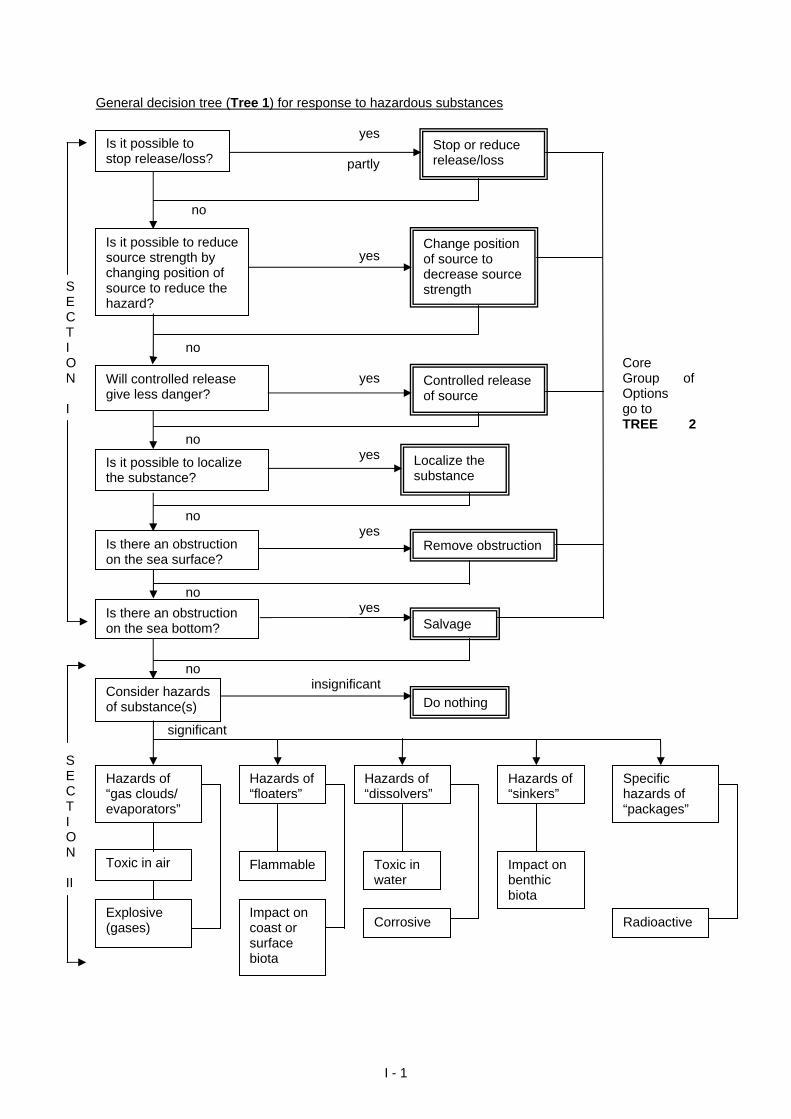
General decision tree (Tree 1) for response to hazardous substances yes partly no yes
S E C T I no O Core N yes Group of Options Options I go to
TREE 2 no yes no yes no yes
no insignificant significant
Is it possible to stop release/loss?
Is it possible to reduce source strength by changing position of source to reduce the hazard?
Stop or reduce release/loss
Change position of source to decrease source strength
Will controlled release give less danger?
Controlled release of source
Is it possible to localize the substance?
Localize the substance
Is there an obstruction on the sea surface?
Remove obstruction
Is there an obstruction on the sea bottom?
Do nothingConsider hazards of substance(s)
Salvage
S E C T I O N II
Hazards of “gas clouds/ evaporators”
Toxic in air
Explosive (gases)
Hazards of “floaters”
Flammable
Impact on coast or surface biota
Hazards of “dissolvers”
Toxic in water
Corrosive
Impact on benthic biota
Hazards of “sinkers”
Specific hazards of “packages”
Radioactive
I - 1
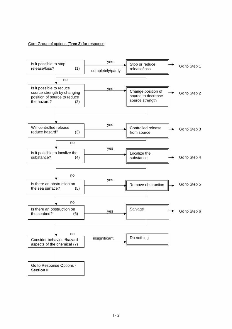
Core Group of options (Tree 2) for response yes Go to Step 1 completely/partly no yes Go to Step 2 yes Go to Step 3 no
yes Go to Step 4 no yes
Is it possible to stop release/loss? (1)
Is it possible to reduce source strength by changing position of source to reduce the hazard? (2)
Will controlled release reduce hazard? (3)
Is it possible to localize the substance? (4)
Localize the substance
Controlled release from source
Change position of source to decrease source strength
Stop or reduce release/loss
Go to Step 5
Is there an obstruction on the sea surface? (5)
Remove obstruction
no yes Go to Step 6
Is there an obstruction on the seabed? (6)
Salvage
no insignificant
Go to Response Options - Section II
Do nothing Consider behaviour/hazard aspects of the chemical (7)
I - 2
STEP 1
yes completely or partly
Stop or reduce release/loss Is it possible to stop release/loss?
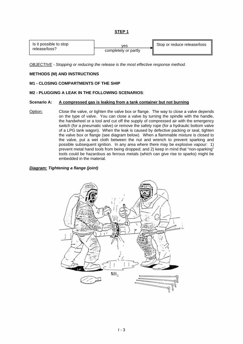
OBJECTIVE - Stopping or reducing the release is the most effective response method. METHODS (M) AND INSTRUCTIONS M1 - CLOSING COMPARTMENTS OF THE SHIP M2 - PLUGGING A LEAK IN THE FOLLOWING SCENARIOS: Scenario A: A compressed gas is leaking from a tank container but not burning Option: Close the valve, or tighten the valve box or flange. The way to close a valve depends
on the type of valve. You can close a valve by turning the spindle with the handle, the handwheel or a tool and cut off the supply of compressed air with the emergency switch (for a pneumatic valve) or remove the safety rope (for a hydraulic bottom valve of a LPG tank wagon). When the leak is caused by defective packing or seal, tighten the valve box or flange (see diagram below). When a flammable mixture is closed to the valve, put a wet cloth between the nut and wrench to prevent sparking and possible subsequent ignition. In any area where there may be explosive vapour: 1) prevent metal hand tools from being dropped; and 2) keep in mind that “non-sparking” tools could be hazardous as ferrous metals (which can give rise to sparks) might be embedded in the material.
Diagram: Tightening a flange (joint)
I - 3
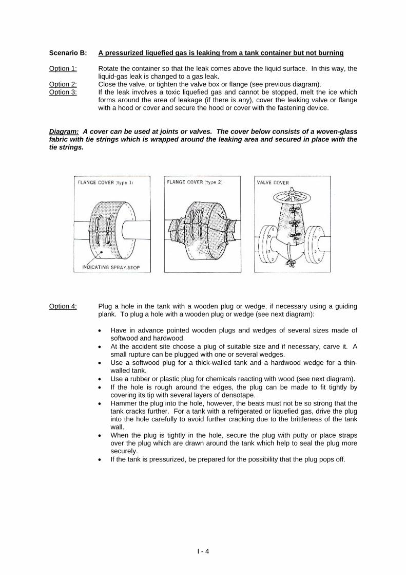
Scenario B: A pressurized liquefied gas is leaking from a tank container but not burning Option 1: Rotate the container so that the leak comes above the liquid surface. In this way, the
liquid-gas leak is changed to a gas leak. Option 2: Close the valve, or tighten the valve box or flange (see previous diagram). Option 3: If the leak involves a toxic liquefied gas and cannot be stopped, melt the ice which
forms around the area of leakage (if there is any), cover the leaking valve or flange with a hood or cover and secure the hood or cover with the fastening device.
Diagram: A cover can be used at joints or valves. The cover below consists of a woven-glass fabric with tie strings which is wrapped around the leaking area and secured in place with the tie strings.
Option 4: Plug a hole in the tank with a wooden plug or wedge, if necessary using a guiding
plank. To plug a hole with a wooden plug or wedge (see next diagram):
Have in advance pointed wooden plugs and wedges of several sizes made of softwood and hardwood.
At the accident site choose a plug of suitable size and if necessary, carve it. A small rupture can be plugged with one or several wedges.
Use a softwood plug for a thick-walled tank and a hardwood wedge for a thin-walled tank.
Use a rubber or plastic plug for chemicals reacting with wood (see next diagram). If the hole is rough around the edges, the plug can be made to fit tightly by
covering its tip with several layers of densotape. Hammer the plug into the hole, however, the beats must not be so strong that the
tank cracks further. For a tank with a refrigerated or liquefied gas, drive the plug into the hole carefully to avoid further cracking due to the brittleness of the tank wall.
When the plug is tightly in the hole, secure the plug with putty or place straps over the plug which are drawn around the tank which help to seal the plug more securely.
If the tank is pressurized, be prepared for the possibility that the plug pops off.
I - 4
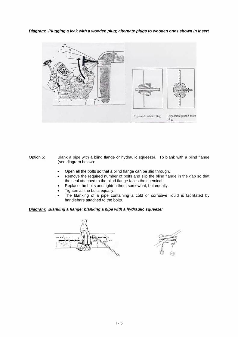
Diagram: Plugging a leak with a wooden plug; alternate plugs to wooden ones shown in insert
Option 5: Blank a pipe with a blind flange or hydraulic squeezer. To blank with a blind flange
(see diagram below):
Open all the bolts so that a blind flange can be slid through. Remove the required number of bolts and slip the blind flange in the gap so that
the seal attached to the blind flange faces the chemical. Replace the bolts and tighten them somewhat, but equally. Tighten all the bolts equally. The blanking of a pipe containing a cold or corrosive liquid is facilitated by
handlebars attached to the bolts. Diagram: Blanking a flange; blanking a pipe with a hydraulic squeezer
I - 5
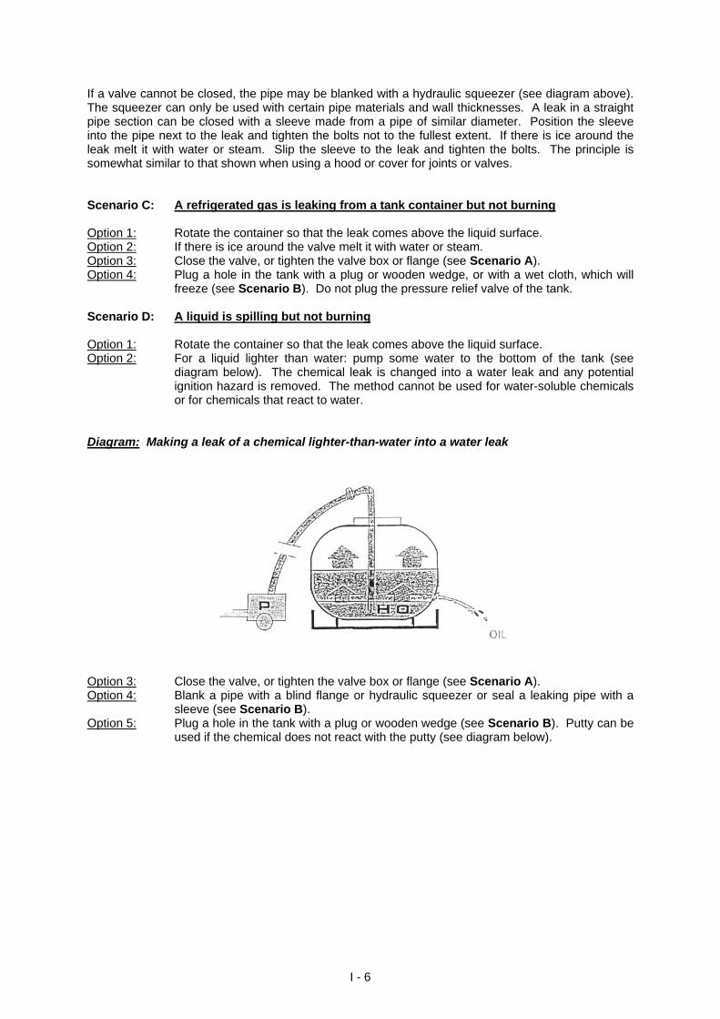
If a valve cannot be closed, the pipe may be blanked with a hydraulic squeezer (see diagram above). The squeezer can only be used with certain pipe materials and wall thicknesses. A leak in a straight pipe section can be closed with a sleeve made from a pipe of similar diameter. Position the sleeve into the pipe next to the leak and tighten the bolts not to the fullest extent. If there is ice around the leak melt it with water or steam. Slip the sleeve to the leak and tighten the bolts. The principle is somewhat similar to that shown when using a hood or cover for joints or valves. Scenario C: A refrigerated gas is leaking from a tank container but not burning Option 1: Rotate the container so that the leak comes above the liquid surface. Option 2: If there is ice around the valve melt it with water or steam. Option 3: Close the valve, or tighten the valve box or flange (see Scenario A). Option 4: Plug a hole in the tank with a plug or wooden wedge, or with a wet cloth, which will
freeze (see Scenario B). Do not plug the pressure relief valve of the tank. Scenario D: A liquid is spilling but not burning Option 1: Rotate the container so that the leak comes above the liquid surface. Option 2: For a liquid lighter than water: pump some water to the bottom of the tank (see
diagram below). The chemical leak is changed into a water leak and any potential ignition hazard is removed. The method cannot be used for water-soluble chemicals or for chemicals that react to water.
Diagram: Making a leak of a chemical lighter-than-water into a water leak
Option 3: Close the valve, or tighten the valve box or flange (see Scenario A). Option 4: Blank a pipe with a blind flange or hydraulic squeezer or seal a leaking pipe with a
sleeve (see Scenario B). Option 5: Plug a hole in the tank with a plug or wooden wedge (see Scenario B). Putty can be
used if the chemical does not react with the putty (see diagram below).
I - 6
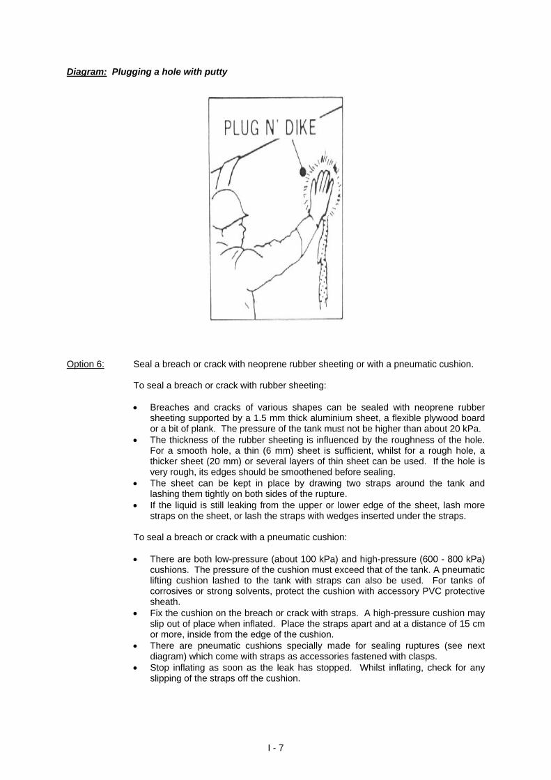
Diagram: Plugging a hole with putty
Option 6: Seal a breach or crack with neoprene rubber sheeting or with a pneumatic cushion. To seal a breach or crack with rubber sheeting:
Breaches and cracks of various shapes can be sealed with neoprene rubber sheeting supported by a 1.5 mm thick aluminium sheet, a flexible plywood board or a bit of plank. The pressure of the tank must not be higher than about 20 kPa.
The thickness of the rubber sheeting is influenced by the roughness of the hole. For a smooth hole, a thin (6 mm) sheet is sufficient, whilst for a rough hole, a thicker sheet (20 mm) or several layers of thin sheet can be used. If the hole is very rough, its edges should be smoothened before sealing.
The sheet can be kept in place by drawing two straps around the tank and lashing them tightly on both sides of the rupture.
If the liquid is still leaking from the upper or lower edge of the sheet, lash more straps on the sheet, or lash the straps with wedges inserted under the straps.
To seal a breach or crack with a pneumatic cushion:
There are both low-pressure (about 100 kPa) and high-pressure (600 - 800 kPa) cushions. The pressure of the cushion must exceed that of the tank. A pneumatic lifting cushion lashed to the tank with straps can also be used. For tanks of corrosives or strong solvents, protect the cushion with accessory PVC protective sheath.
Fix the cushion on the breach or crack with straps. A high-pressure cushion may slip out of place when inflated. Place the straps apart and at a distance of 15 cm or more, inside from the edge of the cushion.
There are pneumatic cushions specially made for sealing ruptures (see next diagram) which come with straps as accessories fastened with clasps.
Stop inflating as soon as the leak has stopped. Whilst inflating, check for any slipping of the straps off the cushion.
I - 7
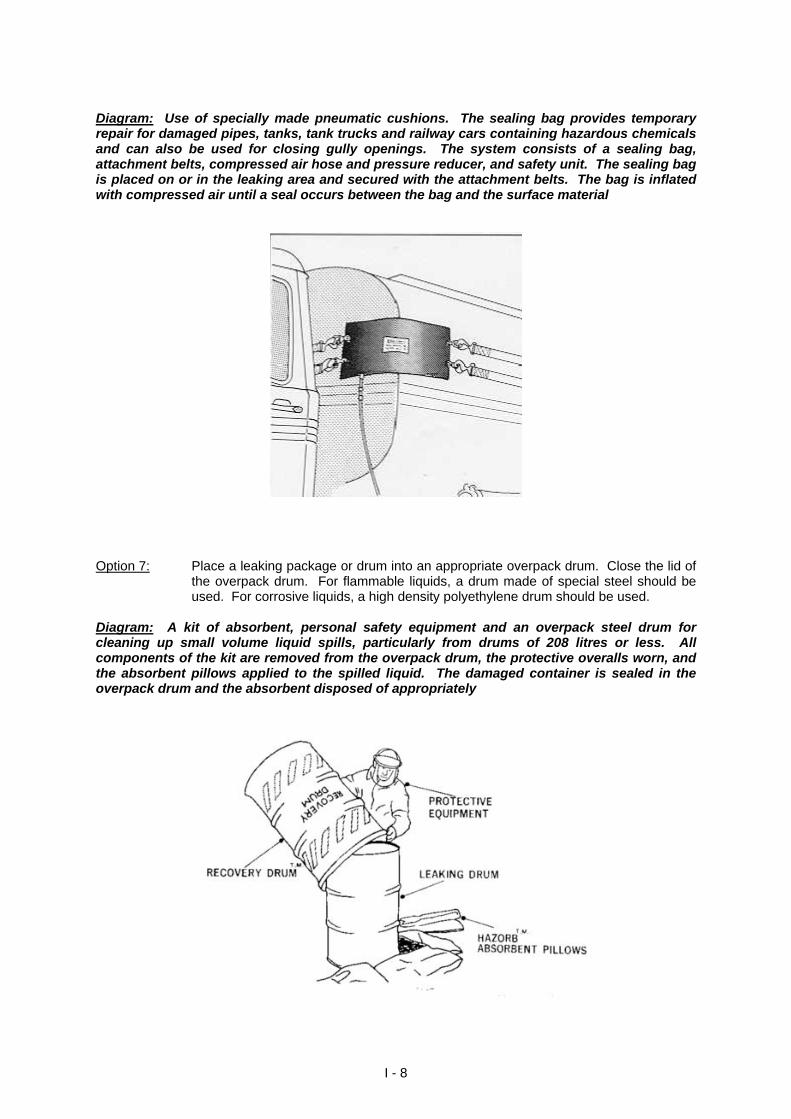
Diagram: Use of specially made pneumatic cushions. The sealing bag provides temporary repair for damaged pipes, tanks, tank trucks and railway cars containing hazardous chemicals and can also be used for closing gully openings. The system consists of a sealing bag, attachment belts, compressed air hose and pressure reducer, and safety unit. The sealing bag is placed on or in the leaking area and secured with the attachment belts. The bag is inflated with compressed air until a seal occurs between the bag and the surface material
Option 7: Place a leaking package or drum into an appropriate overpack drum. Close the lid of
the overpack drum. For flammable liquids, a drum made of special steel should be used. For corrosive liquids, a high density polyethylene drum should be used.
Diagram: A kit of absorbent, personal safety equipment and an overpack steel drum for cleaning up small volume liquid spills, particularly from drums of 208 litres or less. All components of the kit are removed from the overpack drum, the protective overalls worn, and the absorbent pillows applied to the spilled liquid. The damaged container is sealed in the overpack drum and the absorbent disposed of appropriately
I - 8
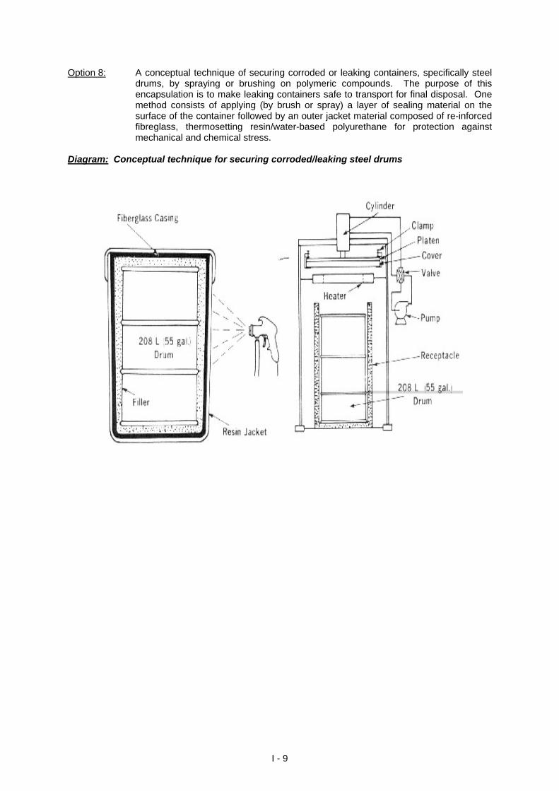
Option 8: A conceptual technique of securing corroded or leaking containers, specifically steel drums, by spraying or brushing on polymeric compounds. The purpose of this encapsulation is to make leaking containers safe to transport for final disposal. One method consists of applying (by brush or spray) a layer of sealing material on the surface of the container followed by an outer jacket material composed of re-inforced fibreglass, thermosetting resin/water-based polyurethane for protection against mechanical and chemical stress.
Diagram: Conceptual technique for securing corroded/leaking steel drums
I - 9
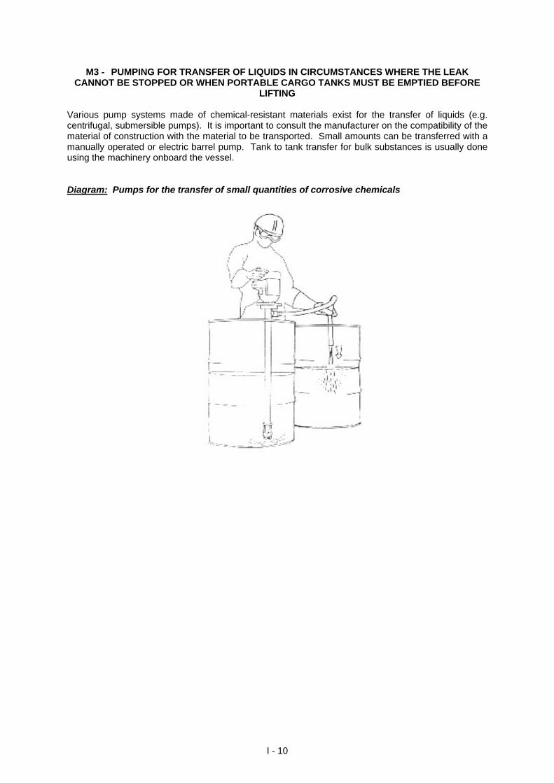
M3 - PUMPING FOR TRANSFER OF LIQUIDS IN CIRCUMSTANCES WHERE THE LEAK CANNOT BE STOPPED OR WHEN PORTABLE CARGO TANKS MUST BE EMPTIED BEFORE
LIFTING Various pump systems made of chemical-resistant materials exist for the transfer of liquids (e.g. centrifugal, submersible pumps). It is important to consult the manufacturer on the compatibility of the material of construction with the material to be transported. Small amounts can be transferred with a manually operated or electric barrel pump. Tank to tank transfer for bulk substances is usually done using the machinery onboard the vessel. Diagram: Pumps for the transfer of small quantities of corrosive chemicals
I - 10
STEP 2
yes
Is it possible to reduce source strength by changing position of source to reduce the hazard? (2)
Change position of source to decrease source strength
OBJECTIVE - The main aim of changing the position of the source (vessel or cargo) is to restrict further possible outflow and/or reduce other hazards. M1 - CHANGE POSITION OF SHIP
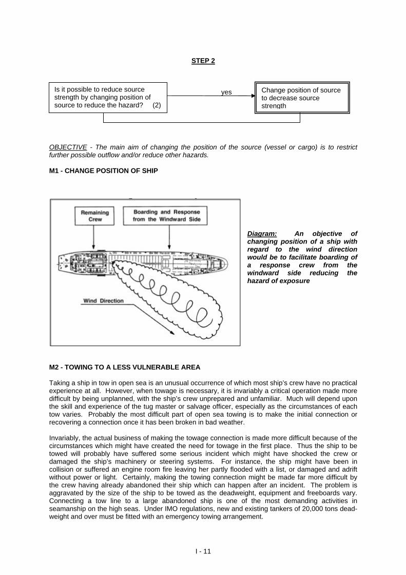
Diagram: An objective of changing position of a ship with regard to the wind direction would be to facilitate boarding of a response crew from the windward side reducing the hazard of exposure
M2 - TOWING TO A LESS VULNERABLE AREA Taking a ship in tow in open sea is an unusual occurrence of which most ship’s crew have no practical experience at all. However, when towage is necessary, it is invariably a critical operation made more difficult by being unplanned, with the ship’s crew unprepared and unfamiliar. Much will depend upon the skill and experience of the tug master or salvage officer, especially as the circumstances of each tow varies. Probably the most difficult part of open sea towing is to make the initial connection or recovering a connection once it has been broken in bad weather. Invariably, the actual business of making the towage connection is made more difficult because of the circumstances which might have created the need for towage in the first place. Thus the ship to be towed will probably have suffered some serious incident which might have shocked the crew or damaged the ship’s machinery or steering systems. For instance, the ship might have been in collision or suffered an engine room fire leaving her partly flooded with a list, or damaged and adrift without power or light. Certainly, making the towing connection might be made far more difficult by the crew having already abandoned their ship which can happen after an incident. The problem is aggravated by the size of the ship to be towed as the deadweight, equipment and freeboards vary. Connecting a tow line to a large abandoned ship is one of the most demanding activities in seamanship on the high seas. Under IMO regulations, new and existing tankers of 20,000 tons dead-weight and over must be fitted with an emergency towing arrangement.
I - 11
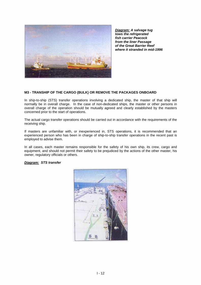
Diagram: A salvage tug tows the refrigerated fish carrier Peacock from the liner Passage of the Great Barrier Reef where it stranded in mid-1996
M3 - TRANSHIP OF THE CARGO (BULK) OR REMOVE THE PACKAGES ONBOARD In ship-to-ship (STS) transfer operations involving a dedicated ship, the master of that ship will normally be in overall charge. In the case of non-dedicated ships, the master or other persons in overall charge of the operation should be mutually agreed and clearly established by the masters concerned prior to the start of operations. The actual cargo transfer operations should be carried out in accordance with the requirements of the receiving ship. If masters are unfamiliar with, or inexperienced in, STS operations, it is recommended that an experienced person who has been in charge of ship-to-ship transfer operations in the recent past is employed to advise them. In all cases, each master remains responsible for the safety of his own ship, its crew, cargo and equipment, and should not permit their safety to be prejudiced by the actions of the other master, his owner, regulatory officials or others. Diagram: STS transfer
I - 12
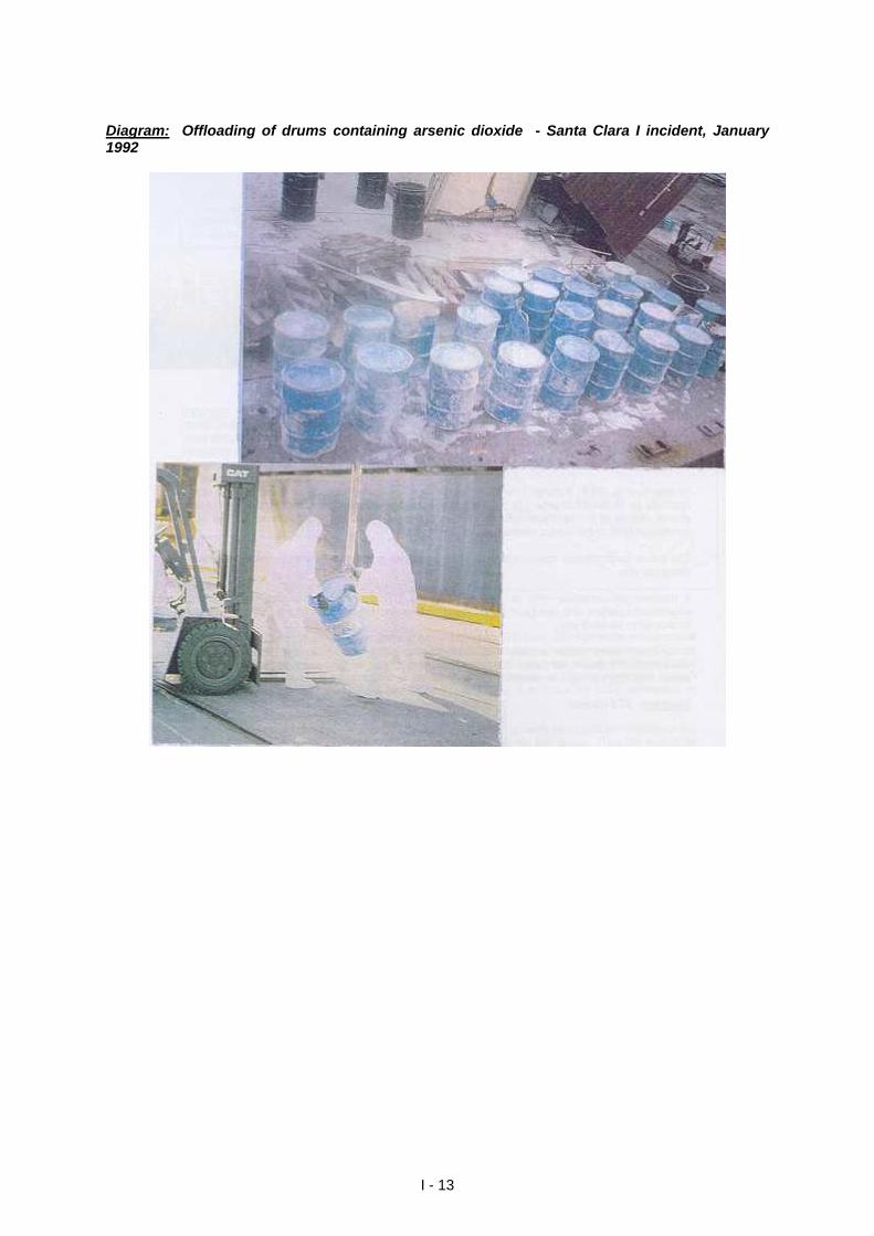
Diagram: Offloading of drums containing arsenic dioxide - Santa Clara I incident, January 1992
I - 13
STEP 3 yes
Will controlled release reduce hazard? (3)
Controlled release from source
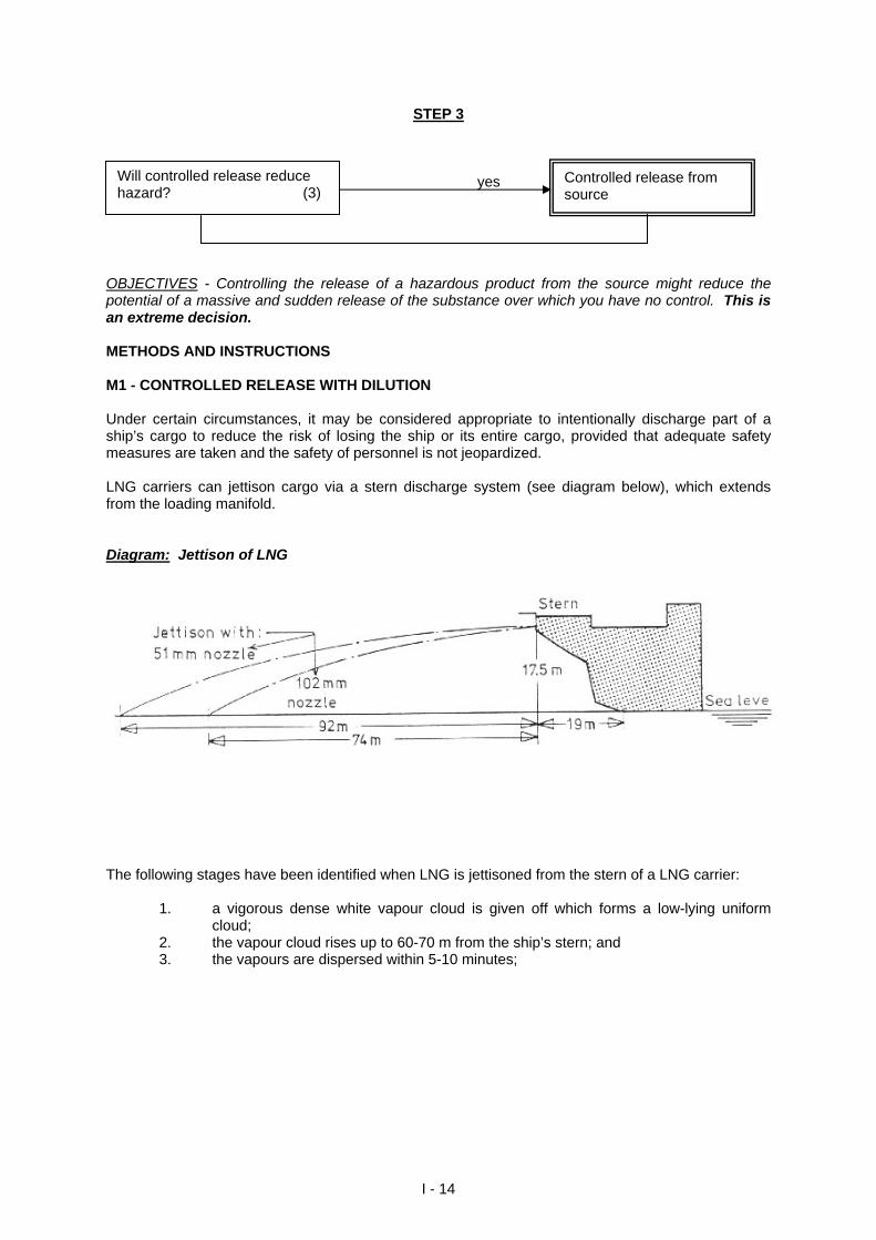
OBJECTIVES - Controlling the release of a hazardous product from the source might reduce the potential of a massive and sudden release of the substance over which you have no control. This is an extreme decision. METHODS AND INSTRUCTIONS M1 - CONTROLLED RELEASE WITH DILUTION Under certain circumstances, it may be considered appropriate to intentionally discharge part of a ship’s cargo to reduce the risk of losing the ship or its entire cargo, provided that adequate safety measures are taken and the safety of personnel is not jeopardized. LNG carriers can jettison cargo via a stern discharge system (see diagram below), which extends from the loading manifold. Diagram: Jettison of LNG
The following stages have been identified when LNG is jettisoned from the stern of a LNG carrier:
1. a vigorous dense white vapour cloud is given off which forms a low-lying uniform cloud;
2. the vapour cloud rises up to 60-70 m from the ship’s stern; and 3. the vapours are dispersed within 5-10 minutes;
I - 14
During trials with such a system, the following observations were made:
1. during discharge, liquid methane was barely visible; 2. no vapour explosions occurred and no LNG pools were formed outside the surface;
and 3. methane was not detected on the ship.
This method is successful subject to the following conditions: 1. the wind speed has to be less than 3 m/s; 2. the wind direction has to be between 30o and 60o off the bow to reduce the possibility
of eddy effects in the cloud; and 3. the LNG nozzle should be able to achieve velocities of 40-50 m/s and as a
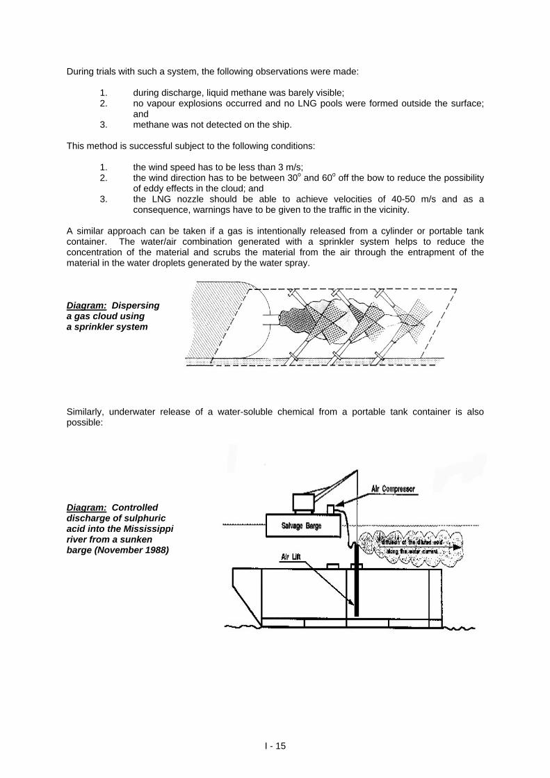
consequence, warnings have to be given to the traffic in the vicinity. A similar approach can be taken if a gas is intentionally released from a cylinder or portable tank container. The water/air combination generated with a sprinkler system helps to reduce the concentration of the material and scrubs the material from the air through the entrapment of the material in the water droplets generated by the water spray. Diagram: Dispersing a gas cloud using a sprinkler system Similarly, underwater release of a water-soluble chemical from a portable tank container is also possible: Diagram: Controlled discharge of sulphuric acid into the Mississippi river from a sunken barge (November 1988)
I - 15
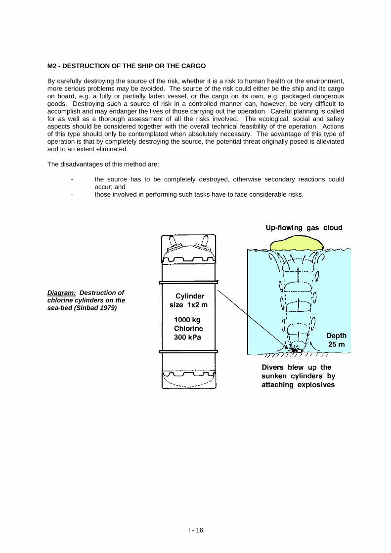
M2 - DESTRUCTION OF THE SHIP OR THE CARGO By carefully destroying the source of the risk, whether it is a risk to human health or the environment, more serious problems may be avoided. The source of the risk could either be the ship and its cargo on board, e.g. a fully or partially laden vessel, or the cargo on its own, e.g. packaged dangerous goods. Destroying such a source of risk in a controlled manner can, however, be very difficult to accomplish and may endanger the lives of those carrying out the operation. Careful planning is called for as well as a thorough assessment of all the risks involved. The ecological, social and safety aspects should be considered together with the overall technical feasibility of the operation. Actions of this type should only be contemplated when absolutely necessary. The advantage of this type of operation is that by completely destroying the source, the potential threat originally posed is alleviated and to an extent eliminated. The disadvantages of this method are: - the source has to be completely destroyed, otherwise secondary reactions could
occur; and - those involved in performing such tasks have to face considerable risks. Diagram: Destruction of chlorine cylinders on the sea-bed (Sinbad 1979)
I - 16
STEP 4 yes
Is it possible to localize the substance? (4)
Localize the substance
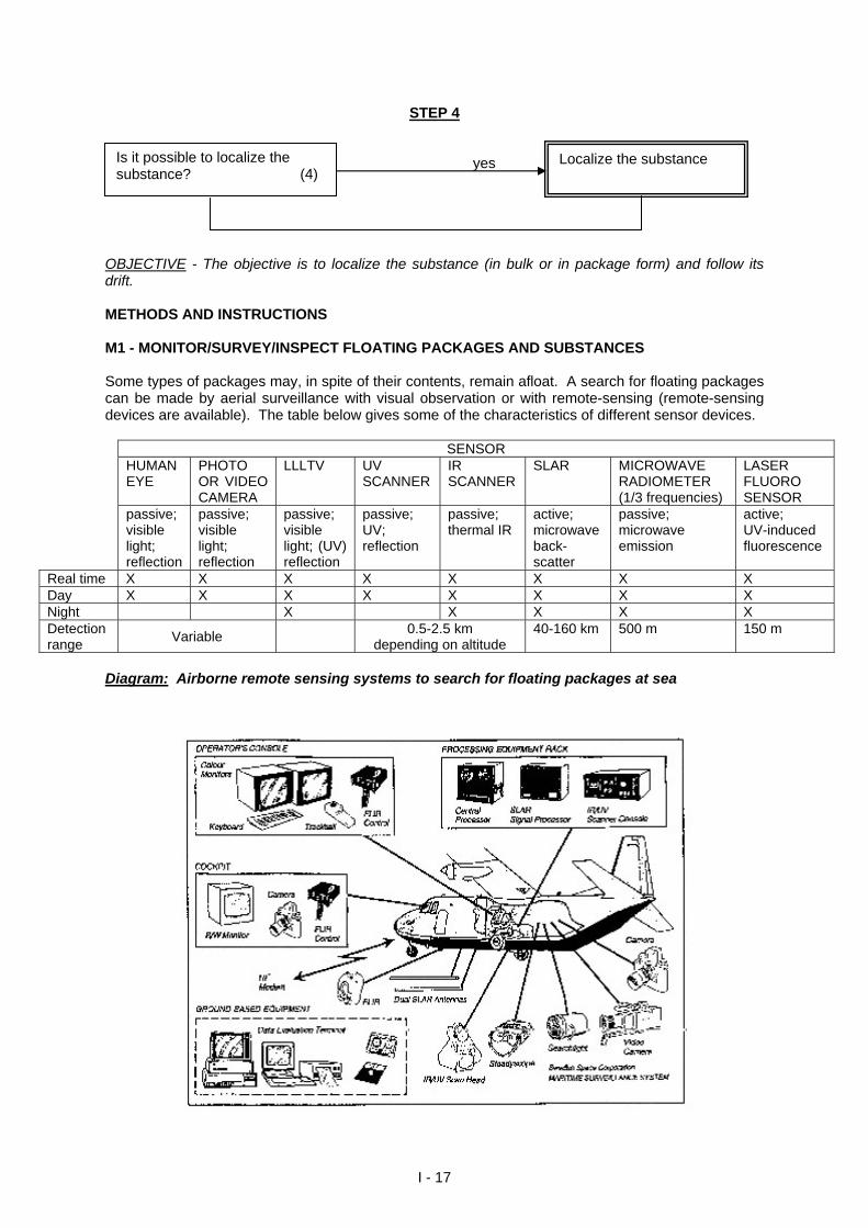
OBJECTIVE - The objective is to localize the substance (in bulk or in package form) and follow its drift. METHODS AND INSTRUCTIONS M1 - MONITOR/SURVEY/INSPECT FLOATING PACKAGES AND SUBSTANCES Some types of packages may, in spite of their contents, remain afloat. A search for floating packages can be made by aerial surveillance with visual observation or with remote-sensing (remote-sensing devices are available). The table below gives some of the characteristics of different sensor devices.
SENSOR HUMAN EYE
PHOTO OR VIDEO CAMERA
LLLTV UV SCANNER
IR SCANNER
SLAR MICROWAVE RADIOMETER (1/3 frequencies)
LASER FLUORO SENSOR
passive; visible light; reflection
passive; visible light; reflection
passive; visible light; (UV) reflection
passive; UV; reflection
passive; thermal IR
active; microwave back- scatter
passive; microwave emission
active; UV-induced fluorescence
Real time X X X X X X X X Day X X X X X X X X Night X X X X X Detection range
Variable 0.5-2.5 km
depending on altitude 40-160 km 500 m 150 m
Diagram: Airborne remote sensing systems to search for floating packages at sea
I - 17
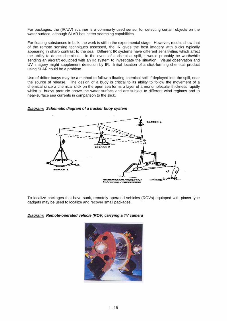
For packages, the (IR/UV) scanner is a commonly used sensor for detecting certain objects on the water surface, although SLAR has better searching capabilities. For floating substances in bulk, the work is still in the experimental stage. However, results show that of the remote sensing techniques assessed, the IR gives the best imagery with slicks typically appearing in sharp contrast to the sea. Different IR systems have different sensitivities which affect the ability to detect chemicals. In the event of a chemical spill, it would probably be worthwhile sending an aircraft equipped with an IR system to investigate the situation. Visual observation and UV imagery might supplement detection by IR. Initial location of a slick-forming chemical product using SLAR could be a problem. Use of drifter buoys may be a method to follow a floating chemical spill if deployed into the spill, near the source of release. The design of a buoy is critical to its ability to follow the movement of a chemical since a chemical slick on the open sea forms a layer of a monomolecular thickness rapidly whilst all buoys protrude above the water surface and are subject to different wind regimes and to near-surface sea currents in comparison to the slick. Diagram: Schematic diagram of a tracker buoy system
To localize packages that have sunk, remotely operated vehicles (ROVs) equipped with pincer-type gadgets may be used to localize and recover small packages. Diagram: Remote-operated vehicle (ROV) carrying a TV camera
I - 18
STEP 5
yes
Is there an obstruction on the sea-surface? (5)
Remove obstruction
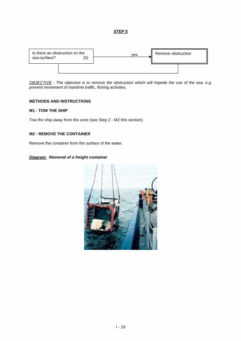
OBJECTIVE - The objective is to remove the obstruction which will impede the use of the sea, e.g. prevent movement of maritime traffic, fishing activities. METHODS AND INSTRUCTIONS M1 - TOW THE SHIP Tow the ship away from the zone (see Step 2 - M2 this section). M2 - REMOVE THE CONTAINER Remove the container from the surface of the water. Diagram: Removal of a freight container
I - 19
STEP 6 yes
Is there an obstruction on the seabed? (6)
Salvage
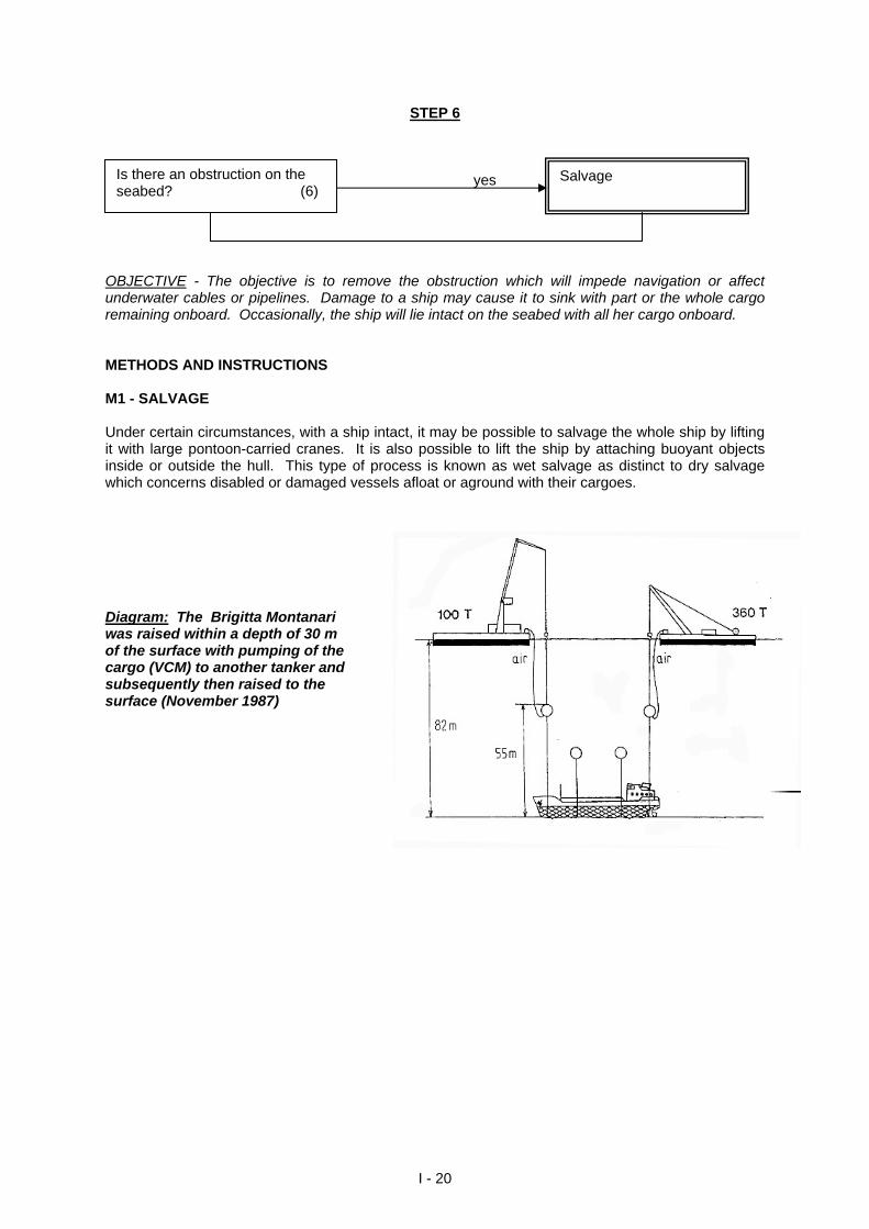
OBJECTIVE - The objective is to remove the obstruction which will impede navigation or affect underwater cables or pipelines. Damage to a ship may cause it to sink with part or the whole cargo remaining onboard. Occasionally, the ship will lie intact on the seabed with all her cargo onboard. METHODS AND INSTRUCTIONS M1 - SALVAGE Under certain circumstances, with a ship intact, it may be possible to salvage the whole ship by lifting it with large pontoon-carried cranes. It is also possible to lift the ship by attaching buoyant objects inside or outside the hull. This type of process is known as wet salvage as distinct to dry salvage which concerns disabled or damaged vessels afloat or aground with their cargoes. Diagram: The Brigitta Montanari was raised within a depth of 30 m of the surface with pumping of the cargo (VCM) to another tanker and subsequently then raised to the surface (November 1987)
I - 20
SECTION II
RESPONSE OPTIONS
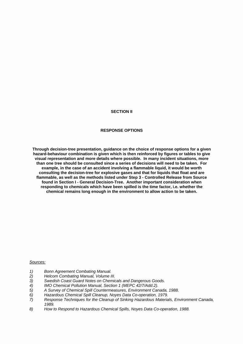
Through decision-tree presentation, guidance on the choice of response options for a given hazard-behaviour combination is given which is then reinforced by figures or tables to give visual representation and more details where possible. In many incident situations, more than one tree should be consulted since a series of decisions will need to be taken. For
example, in the case of an accident involving a flammable liquid, it would be worth consulting the decision-tree for explosive gases and that for liquids that float and are
flammable, as well as the methods listed under Step 3 - Controlled Release from Source found in Section I - General Decision-Tree. Another important consideration when responding to chemicals which have been spilled is the time factor, i.e. whether the
chemical remains long enough in the environment to allow action to be taken. Sources: 1) Bonn Agreement Combating Manual. 2) Helcom Combating Manual, Volume III. 3) Swedish Coast Guard Notes on Chemicals and Dangerous Goods. 4) IMO Chemical Pollution Manual, Section 1 (MEPC 42/7/Add.2). 5) A Survey of Chemical Spill Countermeasures, Environment Canada, 1988. 6) Hazardous Chemical Spill Cleanup, Noyes Data Co-operation, 1979. 7) Response Techniques for the Cleanup of Sinking Hazardous Materials, Environment Canada,
1989. 8) How to Respond to Hazardous Chemical Spills, Noyes Data Co-operation, 1988.
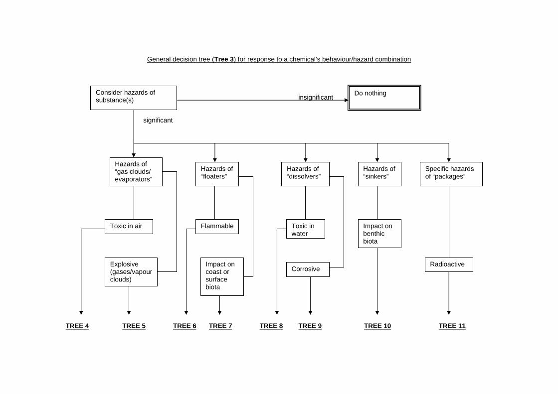
General decision tree (Tree 3) for response to a chemical’s behaviour/hazard combination
insignificant significant
Consider hazards of substance(s)
Do nothing
Hazards of “gas clouds/ evaporators”
Toxic in air
Explosive (gases/vapour clouds)
Hazards of “floaters”
Flammable
Impact on coast or surface biota
Hazards of “dissolvers”
Toxic in water
Corrosive
Impact on benthic biota
Hazards of “sinkers”
Radioactive
Specific hazards of “packages”
TREE 4 TREE 5 TREE 6 TREE 7 TREE 8 TREE 9 TREE 10 TREE 11
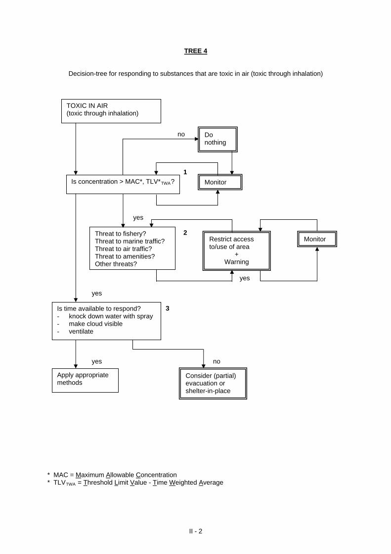
TREE 4
Decision-tree for responding to substances that are toxic in air (toxic through inhalation)
II - 2
no 1 yes 2 yes yes
Threat to fishery? Threat to marine traffic? Threat to air traffic? Threat to amenities? Other threats?
MonitorRestrict access to/use of area
+ Warning
Is concentration > MAC*, TLV*TWA?
Do nothing
Monitor
TOXIC IN AIR (toxic through inhalation)
3 yes no
Consider (partial) evacuation or shelter-in-place
Apply appropriate methods
Is time available to respond? - knock down water with spray - make cloud visible - ventilate
* MAC = Maximum Allowable Concentration * TLVTWA = Threshold Limit Value - Time Weighted Average
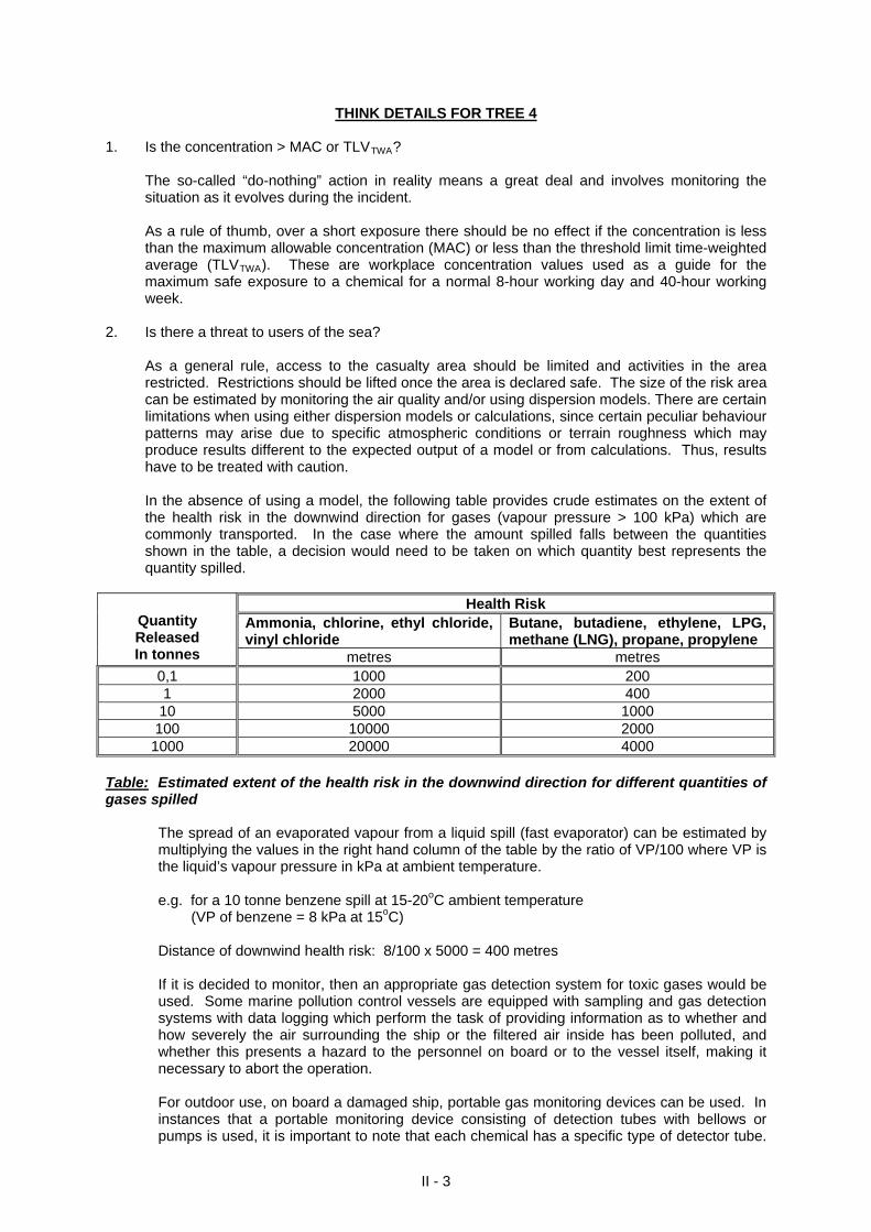
THINK DETAILS FOR TREE 4 1. Is the concentration > MAC or TLVTWA?
The so-called “do-nothing” action in reality means a great deal and involves monitoring the situation as it evolves during the incident. As a rule of thumb, over a short exposure there should be no effect if the concentration is less than the maximum allowable concentration (MAC) or less than the threshold limit time-weighted average (TLVTWA). These are workplace concentration values used as a guide for the maximum safe exposure to a chemical for a normal 8-hour working day and 40-hour working week.
2. Is there a threat to users of the sea?
As a general rule, access to the casualty area should be limited and activities in the area restricted. Restrictions should be lifted once the area is declared safe. The size of the risk area can be estimated by monitoring the air quality and/or using dispersion models. There are certain limitations when using either dispersion models or calculations, since certain peculiar behaviour patterns may arise due to specific atmospheric conditions or terrain roughness which may produce results different to the expected output of a model or from calculations. Thus, results have to be treated with caution. In the absence of using a model, the following table provides crude estimates on the extent of the health risk in the downwind direction for gases (vapour pressure > 100 kPa) which are commonly transported. In the case where the amount spilled falls between the quantities shown in the table, a decision would need to be taken on which quantity best represents the quantity spilled.
Health Risk Ammonia, chlorine, ethyl chloride, vinyl chloride
Butane, butadiene, ethylene, LPG, methane (LNG), propane, propylene
Quantity Released In tonnes metres metres
0,1 1000 200 1 2000 400 10 5000 1000
100 10000 2000 1000 20000 4000
Table: Estimated extent of the health risk in the downwind direction for different quantities of gases spilled
The spread of an evaporated vapour from a liquid spill (fast evaporator) can be estimated by multiplying the values in the right hand column of the table by the ratio of VP/100 where VP is the liquid’s vapour pressure in kPa at ambient temperature.
e.g. for a 10 tonne benzene spill at 15-20oC ambient temperature (VP of benzene = 8 kPa at 15oC) Distance of downwind health risk: 8/100 x 5000 = 400 metres
If it is decided to monitor, then an appropriate gas detection system for toxic gases would be used. Some marine pollution control vessels are equipped with sampling and gas detection systems with data logging which perform the task of providing information as to whether and how severely the air surrounding the ship or the filtered air inside has been polluted, and whether this presents a hazard to the personnel on board or to the vessel itself, making it necessary to abort the operation. For outdoor use, on board a damaged ship, portable gas monitoring devices can be used. In instances that a portable monitoring device consisting of detection tubes with bellows or pumps is used, it is important to note that each chemical has a specific type of detector tube.
II - 3
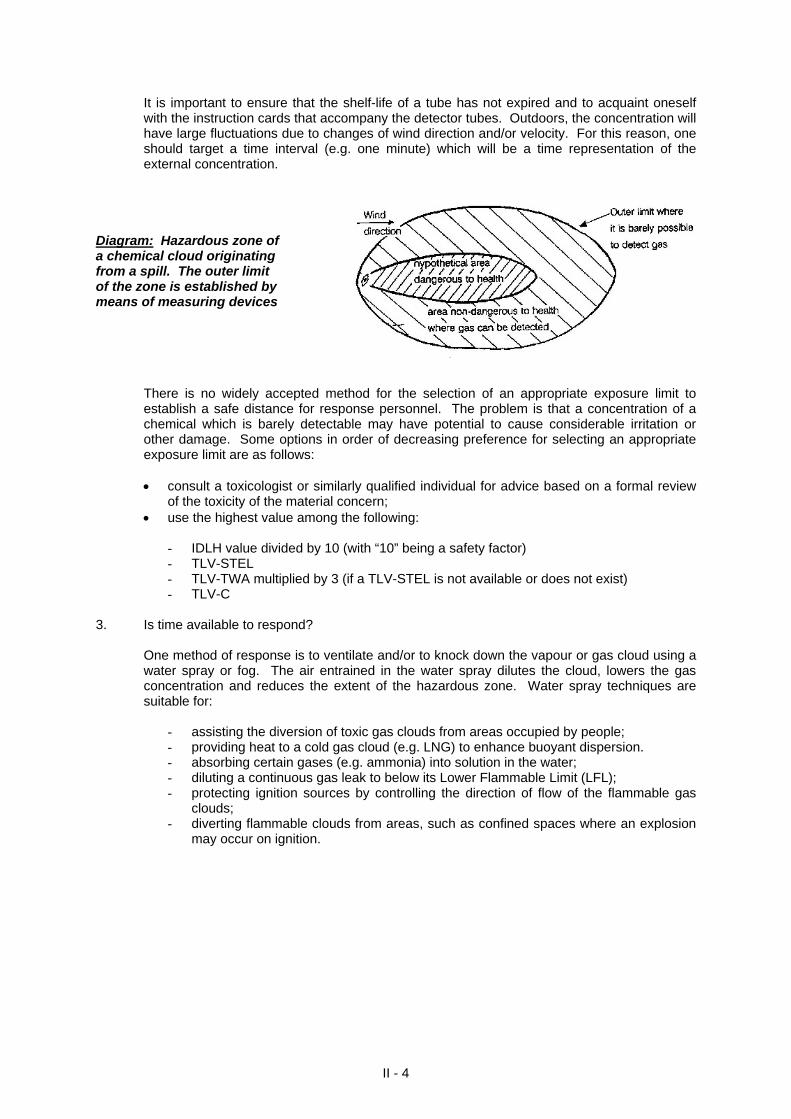
It is important to ensure that the shelf-life of a tube has not expired and to acquaint oneself with the instruction cards that accompany the detector tubes. Outdoors, the concentration will have large fluctuations due to changes of wind direction and/or velocity. For this reason, one should target a time interval (e.g. one minute) which will be a time representation of the external concentration.
Diagram: Hazardous zone of a chemical cloud originating from a spill. The outer limit of the zone is established by means of measuring devices
There is no widely accepted method for the selection of an appropriate exposure limit to establish a safe distance for response personnel. The problem is that a concentration of a chemical which is barely detectable may have potential to cause considerable irritation or other damage. Some options in order of decreasing preference for selecting an appropriate exposure limit are as follows: consult a toxicologist or similarly qualified individual for advice based on a formal review
of the toxicity of the material concern; use the highest value among the following:
- IDLH value divided by 10 (with “10” being a safety factor) - TLV-STEL - TLV-TWA multiplied by 3 (if a TLV-STEL is not available or does not exist) - TLV-C
3. Is time available to respond? One method of response is to ventilate and/or to knock down the vapour or gas cloud using a
water spray or fog. The air entrained in the water spray dilutes the cloud, lowers the gas concentration and reduces the extent of the hazardous zone. Water spray techniques are suitable for:
- assisting the diversion of toxic gas clouds from areas occupied by people; - providing heat to a cold gas cloud (e.g. LNG) to enhance buoyant dispersion. - absorbing certain gases (e.g. ammonia) into solution in the water; - diluting a continuous gas leak to below its Lower Flammable Limit (LFL); - protecting ignition sources by controlling the direction of flow of the flammable gas
clouds; - diverting flammable clouds from areas, such as confined spaces where an explosion
may occur on ignition.
II - 4
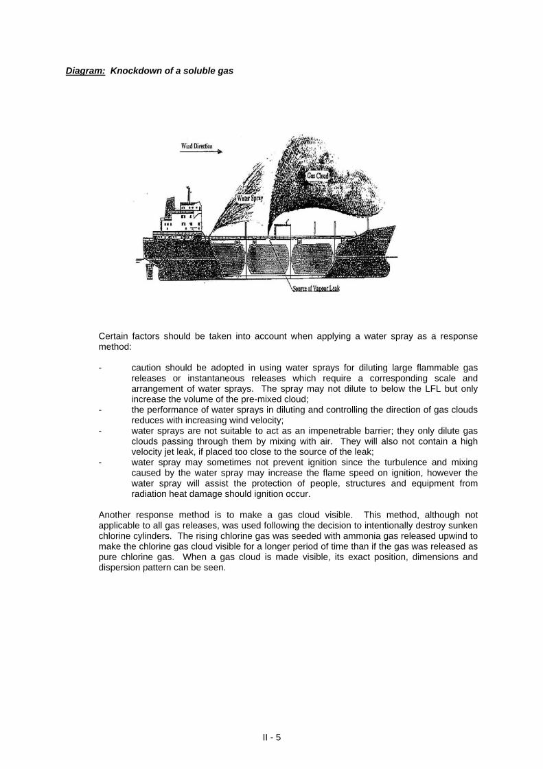
Diagram: Knockdown of a soluble gas
Certain factors should be taken into account when applying a water spray as a response method: - caution should be adopted in using water sprays for diluting large flammable gas
releases or instantaneous releases which require a corresponding scale and arrangement of water sprays. The spray may not dilute to below the LFL but only increase the volume of the pre-mixed cloud;
- the performance of water sprays in diluting and controlling the direction of gas clouds reduces with increasing wind velocity;
- water sprays are not suitable to act as an impenetrable barrier; they only dilute gas clouds passing through them by mixing with air. They will also not contain a high velocity jet leak, if placed too close to the source of the leak;
- water spray may sometimes not prevent ignition since the turbulence and mixing caused by the water spray may increase the flame speed on ignition, however the water spray will assist the protection of people, structures and equipment from radiation heat damage should ignition occur.
Another response method is to make a gas cloud visible. This method, although not applicable to all gas releases, was used following the decision to intentionally destroy sunken chlorine cylinders. The rising chlorine gas was seeded with ammonia gas released upwind to make the chlorine gas cloud visible for a longer period of time than if the gas was released as pure chlorine gas. When a gas cloud is made visible, its exact position, dimensions and dispersion pattern can be seen.
II - 5
II - 6
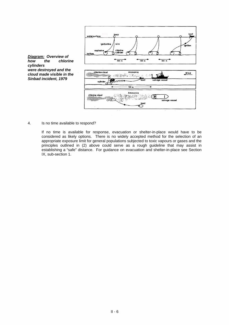
Diagram: Overview of how the chlorine cylinders were destroyed and the cloud made visible in the Sinbad incident, 1979 4. Is no time available to respond?
If no time is available for response, evacuation or shelter-in-place would have to be considered as likely options. There is no widely accepted method for the selection of an appropriate exposure limit for general populations subjected to toxic vapours or gases and the principles outlined in (2) above could serve as a rough guideline that may assist in establishing a “safe” distance. For guidance on evacuation and shelter-in-place see Section IX, sub-section 1.
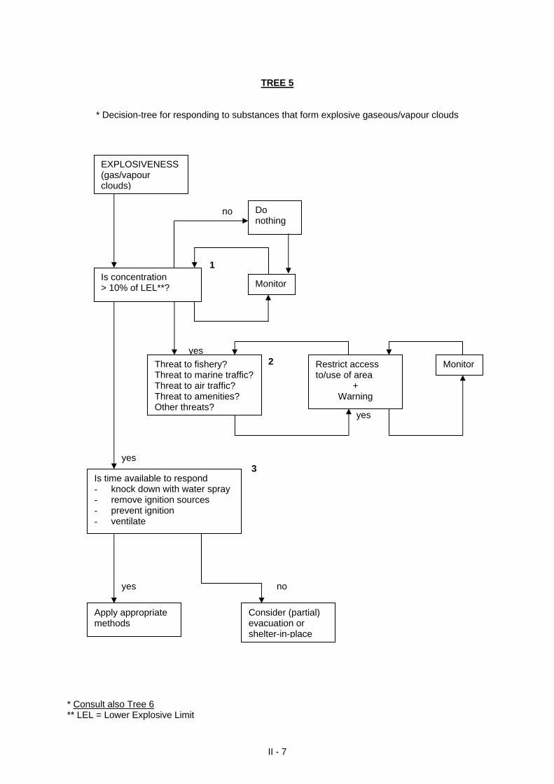
TREE 5
* Decision-tree for responding to substances that form explosive gaseous/vapour clouds
II - 7
no 1 yes 2 yes yes 3
Threat to fishery? Threat to marine traffic? Threat to air traffic? Threat to amenities? Other threats?
Monitor Restrict access to/use of area
+ Warning
Do nothing
Monitor Is concentration > 10% of LEL**?
EXPLOSIVENESS (gas/vapour clouds)
yes no
Is time available to respond - knock down with water spray - remove ignition sources - prevent ignition - ventilate
Apply appropriate
methods Consider (partial) evacuation or shelter-in-place
* Consult also Tree 6 ** LEL = Lower Explosive Limit
THINK DETAILS FOR TREE 5
1. Is the concentration > 10% of LEL?
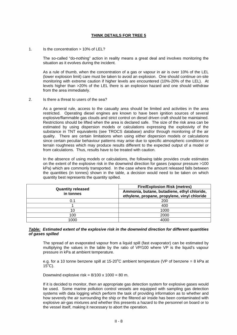
The so-called “do-nothing” action in reality means a great deal and involves monitoring the situation as it evolves during the incident. As a rule of thumb, when the concentration of a gas or vapour in air is over 10% of the LEL (lower explosion limit) care must be taken to avoid an explosion. One should continue on-site monitoring with extreme caution if higher levels are encountered (10%-20% of the LEL). At levels higher than >20% of the LEL there is an explosion hazard and one should withdraw from the area immediately.
2. Is there a threat to users of the sea?
As a general rule, access to the casualty area should be limited and activities in the area restricted. Operating diesel engines are known to have been ignition sources of several explosive/flammable gas clouds and strict control on diesel driven craft should be maintained. Restrictions should be lifted when the area is declared safe. The size of the risk area can be estimated by using dispersion models or calculations expressing the explosivity of the substance in TNT equivalents (see TROCS database) and/or through monitoring of the air quality. There are certain limitations when using either dispersion models or calculations since certain peculiar behaviour patterns may arise due to specific atmospheric conditions or terrain roughness which may produce results different to the expected output of a model or from calculations. Thus, results have to be treated with caution. In the absence of using models or calculations, the following table provides crude estimates on the extent of the explosive risk in the downwind direction for gases (vapour pressure >100 kPa) which are commonly transported. In the case where the amount released falls between the quantities (in tonnes) shown in the table, a decision would need to be taken on which quantity best represents the quantity spilled.
Fire/Explosion Risk (metres)
Quantity released in tonnes Ammonia, butane, butadiene, ethyl chloride,
ethylene, propane, propylene, vinyl chloride 0.1 200 1 400 10 1000
100 2000 1000 4000
Table: Estimated extent of the explosive risk in the downwind direction for different quantities of gases spilled
The spread of an evaporated vapour from a liquid spill (fast evaporator) can be estimated by multiplying the values in the table by the ratio of VP/100 where VP is the liquid’s vapour pressure in kPa at ambient temperature.
e.g. for a 10 tonne benzene spill at 15-20oC ambient temperature (VP of benzene = 8 kPa at 15oC).
Downwind explosive risk = 8/100 x 1000 = 80 m. If it is decided to monitor, then an appropriate gas detection system for explosive gases would be used. Some marine pollution control vessels are equipped with sampling gas detection systems with data logging which perform the task of providing information as to whether and how severely the air surrounding the ship or the filtered air inside has been contaminated with explosive air-gas mixtures and whether this presents a hazard to the personnel on board or to the vessel itself, making it necessary to abort the operation.
II - 8
For outdoor use, on board a damaged ship, a portable explosimeter should be used. It is important to check in the manual of the explosimeter if it can be used for the gas or vapour present in the air. It also needs regular calibration and this should be done according to the manual instructions. Certain factors may give rise to erratic readings:
- lower readings than actual due to the low heat of combustion of the gas or vapour, e.g.
carbon disulphide; - a decrease in the values of the readings during measurements due to polymer formation
of the chemicals which accumulates on the sensor (polymerising chemicals such as styrene, acrylonitrile). This problem can be anticipated for certain liquid chemicals since these are carried with inhibitor additions;
- invalid readings due to a concentration of oxygen of < 19.5%; - total failure of the explosimeter due to corrosion or loss of catalytic property of the
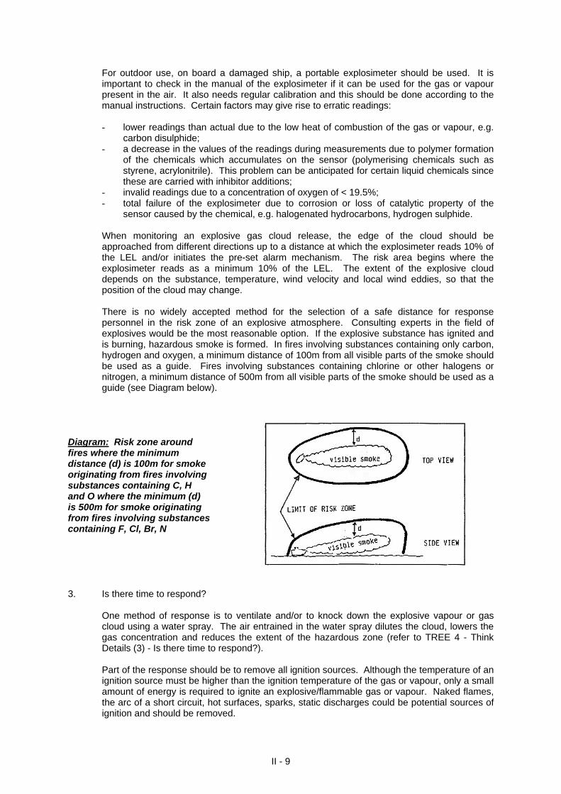
sensor caused by the chemical, e.g. halogenated hydrocarbons, hydrogen sulphide. When monitoring an explosive gas cloud release, the edge of the cloud should be approached from different directions up to a distance at which the explosimeter reads 10% of the LEL and/or initiates the pre-set alarm mechanism. The risk area begins where the explosimeter reads as a minimum 10% of the LEL. The extent of the explosive cloud depends on the substance, temperature, wind velocity and local wind eddies, so that the position of the cloud may change. There is no widely accepted method for the selection of a safe distance for response personnel in the risk zone of an explosive atmosphere. Consulting experts in the field of explosives would be the most reasonable option. If the explosive substance has ignited and is burning, hazardous smoke is formed. In fires involving substances containing only carbon, hydrogen and oxygen, a minimum distance of 100m from all visible parts of the smoke should be used as a guide. Fires involving substances containing chlorine or other halogens or nitrogen, a minimum distance of 500m from all visible parts of the smoke should be used as a guide (see Diagram below).
Diagram: Risk zone around fires where the minimum distance (d) is 100m for smoke originating from fires involving substances containing C, H and O where the minimum (d) is 500m for smoke originating from fires involving substances containing F, Cl, Br, N 3. Is there time to respond?
One method of response is to ventilate and/or to knock down the explosive vapour or gas cloud using a water spray. The air entrained in the water spray dilutes the cloud, lowers the gas concentration and reduces the extent of the hazardous zone (refer to TREE 4 - Think Details (3) - Is there time to respond?). Part of the response should be to remove all ignition sources. Although the temperature of an ignition source must be higher than the ignition temperature of the gas or vapour, only a small amount of energy is required to ignite an explosive/flammable gas or vapour. Naked flames, the arc of a short circuit, hot surfaces, sparks, static discharges could be potential sources of ignition and should be removed.
II - 9
Operating diesel engines are known to have been ignition sources of several explosive/flammable gas clouds. A ship’s diesel driven emergency fire pumps could be a source of ignition. The discharge of CO2 from a fire extinguisher into the air intake of a diesel engine will stop it. Furthermore, non-sparking hand tools and explosive proof equipment and working methods that do not produce sparks should be used.
4. Is there no time to respond?
If no time is available to respond, evacuation or shelter-in-place would have to be considered as likely options. There is no widely accepted method for the selection of an appropriate safe distance from an explosive zone. The principles outlined in (2) above could serve as a rough guideline that may assist in establishing a “safe distance”. For guidance on evacuation and shelter-in-place see Section IX, sub-section 1.
II - 10
TREE 6
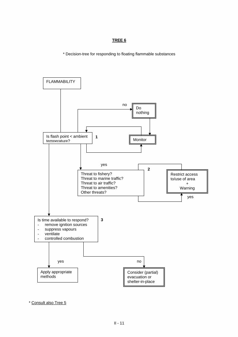
* Decision-tree for responding to floating flammable substances
II - 11
no 1 yes 2 yes
Is flash point < ambient temperature?
Do nothing
Threat to fishery?
Monitor
Restrict access to/use of area
+ Warning
Threat to marine traffic? Threat to air traffic? Threat to amenities? Other threats?
FLAMMABILITY
3 yes no
Consider (partial) evacuation or shelter-in-place
Apply appropriate methods
Is time available to respond? - remove ignition sources - suppress vapours - ventilate - controlled combustion
* Consult also Tree 5
THINK DETAILS FOR TREE 6 1. Is the flash point < ambient temperature?
The so-called “do-nothing” action in reality means a great deal and involves monitoring the situation as it evolves during the incident. The flash point of a liquid is the lowest temperature of a material at which vapours over its liquid surface will ignite and burn when exposed to a specified ignition source. As a rule of thumb, a liquid which has a flash point close to the ambient temperature, or has a lower flash point relative to the ambient temperature, will be easily ignited by a spark or naked flame. Any liquid with a flash point < 21oC can be considered highly flammable. There must also be sufficient oxygen and vapours available in the vapour-air mixture to support and sustain combustion. The minimum concentration of a vapour that will ignite and propagate a flame is the Lower Flammable Limit (LFL). The flash point is theoretically the temperature at atmospheric pressure to which a liquid must be raised to produce a vapour over its surface equivalent to its LFL. The words flammable and explosive are also used interchangeably such that LFL values typically equal LEL. Similar to explosive gaseous/vapour clouds, the same rule of thumb applies, i.e. care must be taken when the concentration of the vapour exceeds 10% of the LFL (refer to TREE 5 - Think Details (1) - Is the concentration > 10% of LEL?)
2. Is there a threat to users of the sea?
As a general rule, access to the casualty area should be limited and activities in the area restricted. Restrictions should be lifted once the area is declared safe. The size of the risk area can be estimated by using dispersion models. If it is decided to monitor, then an appropriate gas detection system for flammable (explosive) vapours would be used. In general, the same think details apply here as for TREE 5 (refer to TREE 5 - Think Details (2) - Is there a threat to users of the sea?).
3. Is there time to respond?
Part of the response should be to remove all ignition sources such as naked flames, hot surfaces, sparks (refer to TREE 5 - Think Details (3) - Is there time to respond?).
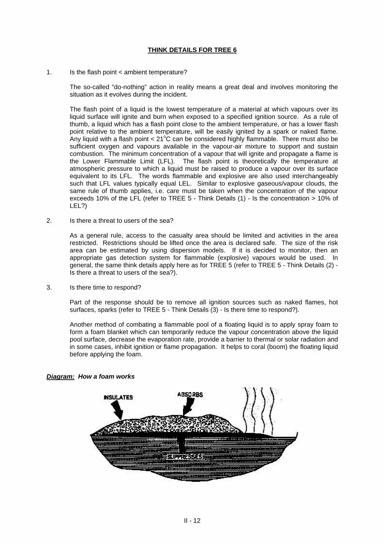
Another method of combating a flammable pool of a floating liquid is to apply spray foam to
form a foam blanket which can temporarily reduce the vapour concentration above the liquid pool surface, decrease the evaporation rate, provide a barrier to thermal or solar radiation and in some cases, inhibit ignition or flame propagation. It helps to coral (boom) the floating liquid before applying the foam.
Diagram: How a foam works
II - 12
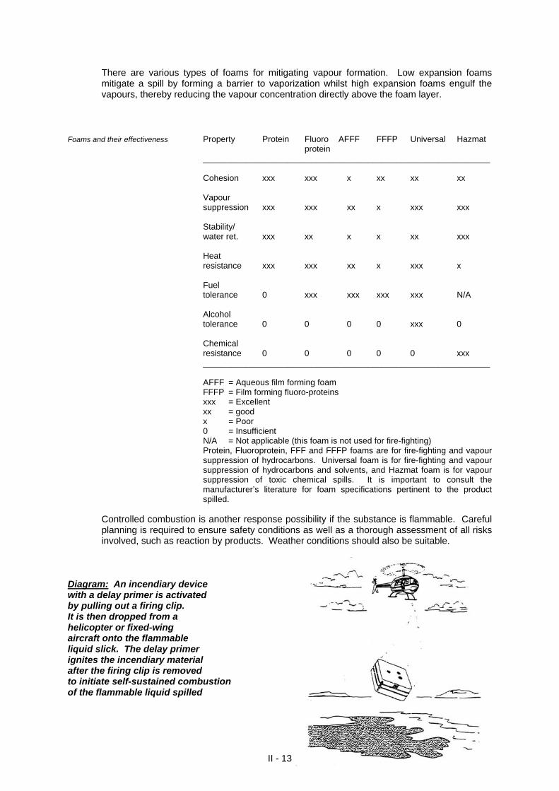
There are various types of foams for mitigating vapour formation. Low expansion foams mitigate a spill by forming a barrier to vaporization whilst high expansion foams engulf the vapours, thereby reducing the vapour concentration directly above the foam layer.
Foams and their effectiveness Property Protein Fluoro AFFF FFFP Universal Hazmat protein _____________________________________________________________ Cohesion xxx xxx x xx xx xx Vapour suppression xxx xxx xx x xxx xxx Stability/ water ret. xxx xx x x xx xxx Heat resistance xxx xxx xx x xxx x Fuel tolerance 0 xxx xxx xxx xxx N/A Alcohol tolerance 0 0 0 0 xxx 0 Chemical resistance 0 0 0 0 0 xxx _____________________________________________________________ AFFF = Aqueous film forming foam FFFP = Film forming fluoro-proteins xxx = Excellent xx = good x = Poor 0 = Insufficient N/A = Not applicable (this foam is not used for fire-fighting) Protein, Fluoroprotein, FFF and FFFP foams are for fire-fighting and vapour
suppression of hydrocarbons. Universal foam is for fire-fighting and vapour suppression of hydrocarbons and solvents, and Hazmat foam is for vapour suppression of toxic chemical spills. It is important to consult the manufacturer’s literature for foam specifications pertinent to the product spilled.
Controlled combustion is another response possibility if the substance is flammable. Careful
planning is required to ensure safety conditions as well as a thorough assessment of all risks involved, such as reaction by products. Weather conditions should also be suitable.
II - 13
Diagram: An incendiary device with a delay primer is activated by pulling out a firing clip. It is then dropped from a helicopter or fixed-wing aircraft onto the flammable liquid slick. The delay primer ignites the incendiary material after the firing clip is removed to initiate self-sustained combustion of the flammable liquid spilled
4. Is there no time to respond?
If no time is available to respond, evacuation or shelter-in-place would have to be considered as likely options. For guidance on evacuation and shelter-in-place see Section IX, sub-section 1.
II - 14
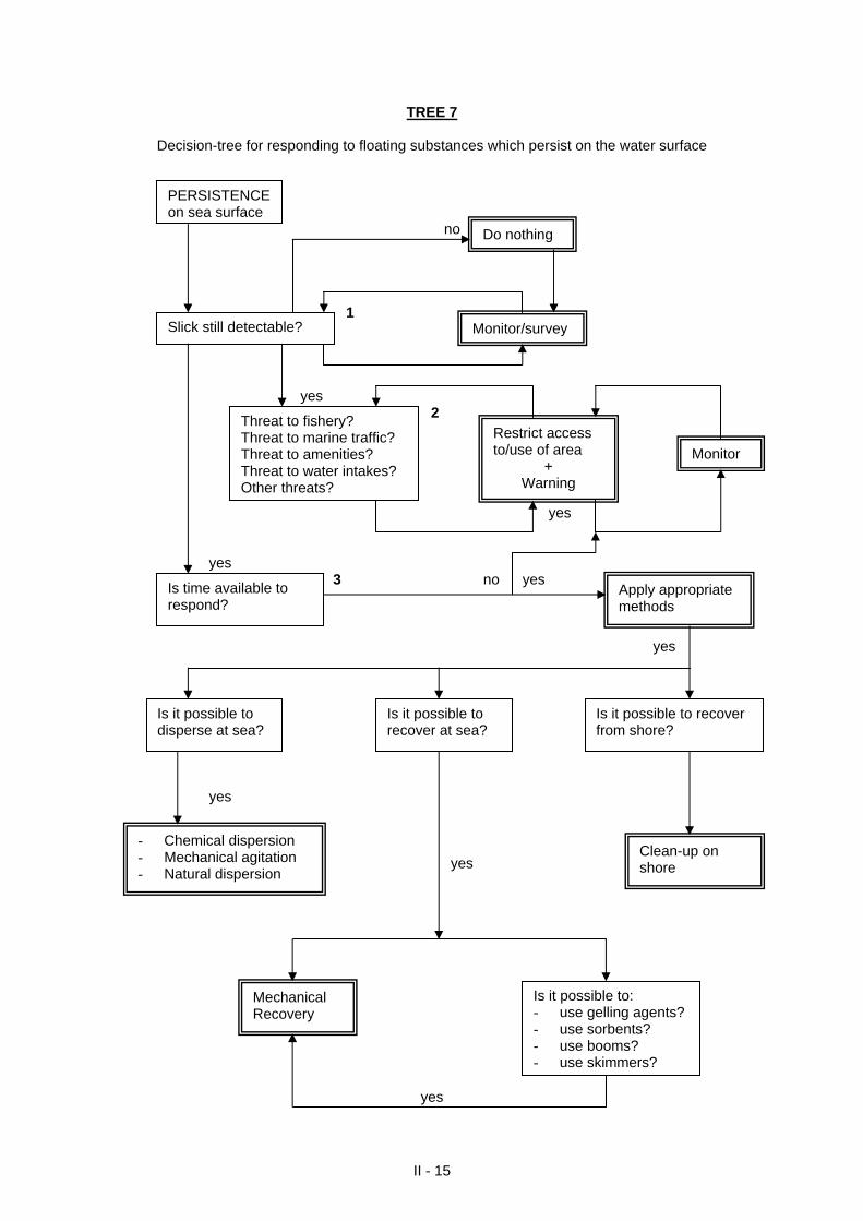
TREE 7
Decision-tree for responding to floating substances which persist on the water surface no 1
II - 15
yes 2 yes yes 3 no yes yes yes yes
yes
PERSISTENCE on sea surface
Slick still detectable?
Do nothing
Is time available to respond?
Apply appropriate methods
- Chemical dispersion - Mechanical agitation - Natural dispersion
Monitor/survey
Mechanical Recovery
Clean-up on shore
Is it possible to: - use gelling agents? - use sorbents? - use booms? - use skimmers?
Is it possible to recover at sea?
Is it possible to recover from shore?
Is it possible to disperse at sea?
Threat to fishery? Threat to marine traffic? Threat to amenities? Threat to water intakes? Other threats?
Restrict access to/use of area
+ Warning
Monitor
THINK DETAILS FOR TREE 7
1. Is the slick still detectable?
The so-called “do-nothing” action in reality means a great deal and involves monitoring the situation as it evolves during the incident. Due to evaporation and/or dissolution, spills of floating chemicals belonging to the floater-evaporator, floater-evaporator-dissolver or floater-dissolver categories will disappear from the water surface relatively fast (< 10 hours). Chemicals which are considered as pure floaters (liquids: density < 1.03, solubility < 0.1%, vapour pressure < 0.3 kPa; solids: density < 1.03, solubility < 10%) are those which could be persistent enough to cause a nuisance on the sea-surface. The viscosity of a hazardous chemical has significant importance for controlling the behaviour of a floater because it indicates how fluid the chemical is. Certain pure floaters of low viscosity will spread quickly to form a monomolecular film in a short time. They will rapidly disperse by turbulence due to waves and currents.
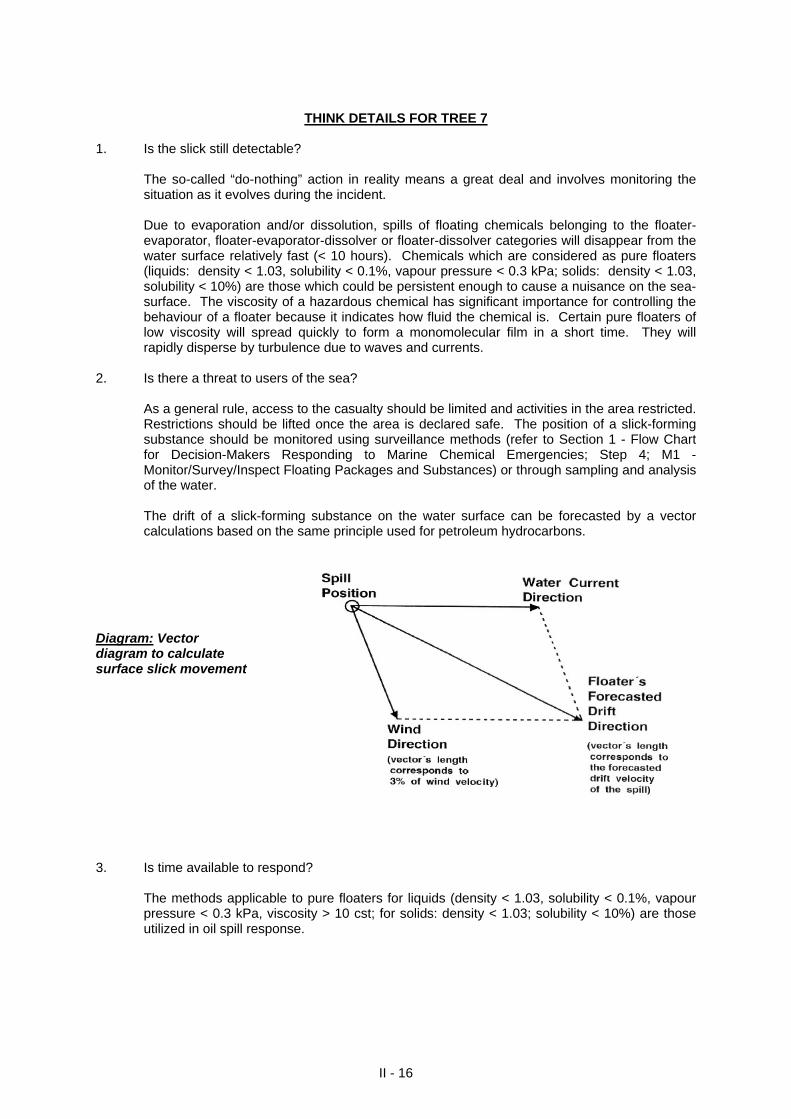
2. Is there a threat to users of the sea?
As a general rule, access to the casualty should be limited and activities in the area restricted. Restrictions should be lifted once the area is declared safe. The position of a slick-forming substance should be monitored using surveillance methods (refer to Section 1 - Flow Chart for Decision-Makers Responding to Marine Chemical Emergencies; Step 4; M1 - Monitor/Survey/Inspect Floating Packages and Substances) or through sampling and analysis of the water. The drift of a slick-forming substance on the water surface can be forecasted by a vector calculations based on the same principle used for petroleum hydrocarbons.
Diagram: Vector diagram to calculate surface slick movement
3. Is time available to respond?
The methods applicable to pure floaters for liquids (density < 1.03, solubility < 0.1%, vapour pressure < 0.3 kPa, viscosity > 10 cst; for solids: density < 1.03; solubility < 10%) are those utilized in oil spill response.
II - 16
3a. Is it possible to disperse at sea? Dispersion facilitates the dilution of the spilled material over an area to reduce the
concentration of the material to below the recommended limits by breaking up the floating liquid into tiny droplets that no longer float but become finely dispersed in the water column. The chemical dispersion technique utilizes surfactants which reduce interfacial tension between oil and water, diluting the chemical and facilitating an increase in the rate of biological and physical degradation. The table below presents laboratory results of the ability of selected floating chemicals to be dispersed by the oil dispersant Finasol OSR5.
“Solubility” Gain in (% mass at 20oC) dispersibility aniline 3.7 +3 n-butyl acetate 0.68 +17 butyl acrylate 0.2 +55 n-butilic alcohol 7.7 0 dodecyl benzene < 5.10-4 +44 ethyl benzene 0.015 +50 2-ethyl hexanol 0.1 +49 hexanol 0.58 0 MIBK 1.28 +13 xylene 0.011 +50 styrene 0.03 +62 Table: Dispersion ability (laboratory results) of selected chemicals in contact with Finasol
OSR5. Although laboratory experiments have been conducted successfully in the field, the chemical
dispersion technique may be difficult to apply since most floating chemicals are colourless and spread very quickly.
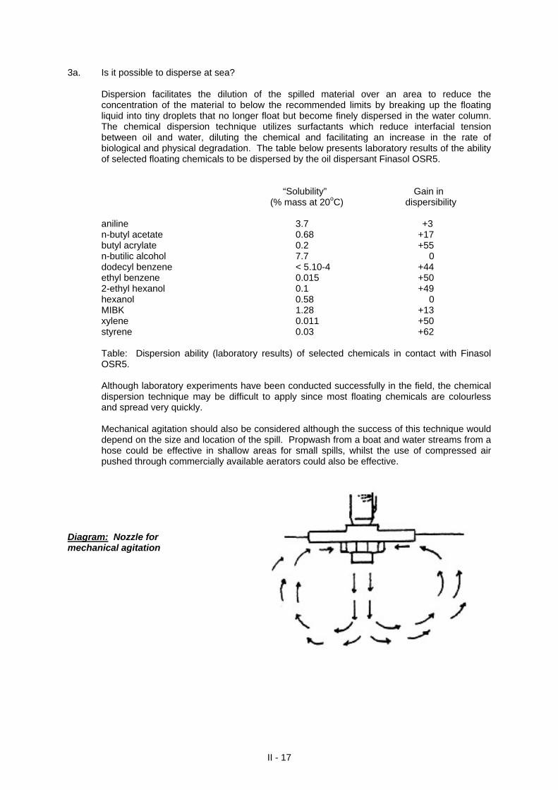
Mechanical agitation should also be considered although the success of this technique would
depend on the size and location of the spill. Propwash from a boat and water streams from a hose could be effective in shallow areas for small spills, whilst the use of compressed air pushed through commercially available aerators could also be effective.
Diagram: Nozzle for mechanical agitation
II - 17
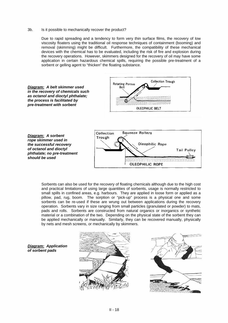
3b. Is it possible to mechanically recover the product? Due to rapid spreading and a tendency to form very thin surface films, the recovery of low
viscosity floaters using the traditional oil response techniques of containment (booming) and removal (skimming) might be difficult. Furthermore, the compatibility of these mechanical devices with the chemical has to be evaluated, including the risk of fire and explosion during the recovery operations. However, skimmers designed for the recovery of oil may have some application in certain hazardous chemical spills, requiring the possible pre-treatment of a sorbent or gelling agent to “thicken” the floating substance.
Diagram: A belt skimmer used in the recovery of chemicals such as octanol and dioctyl phthalate; the process is facilitated by pre-treatment with sorbent Diagram: A sorbent rope skimmer used in the successful recovery of octanol and dioctyl phthalate; no pre-treatment should be used Sorbents can also be used for the recovery of floating chemicals although due to the high cost
and practical limitations of using large quantities of sorbents, usage is normally restricted to small spills in confined areas, e.g. harbours. They are applied in loose form or applied as a pillow, pad, rug, boom. The sorption or “pick-up” process is a physical one and some sorbents can be re-used if these are wrung out between applications during the recovery operation. Sorbents vary in size ranging from small particles (granulated or powder) to mats, pads and rolls. Sorbents are constructed from natural organics or inorganics or synthetic material or a combination of the two. Depending on the physical state of the sorbent they can be applied mechanically or manually. Similarly, they can be recovered manually, physically by nets and mesh screens, or mechanically by skimmers.
Diagram: Application of sorbent pads
II - 18
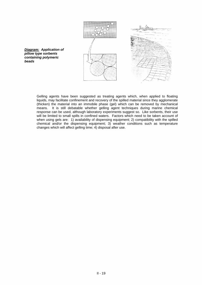
Diagram: Application of pillow type sorbents containing polymeric beads Gelling agents have been suggested as treating agents which, when applied to floating
liquids, may facilitate confinement and recovery of the spilled material since they agglomerate (thicken) the material into an immobile phase (gel) which can be removed by mechanical means. It is still debatable whether gelling agent techniques during marine chemical response can be used, although laboratory experiments suggest so. Like sorbents, their use will be limited to small spills in confined waters. Factors which need to be taken account of when using gels are: 1) availability of dispensing equipment; 2) compatibility with the spilled chemical and/or the dispensing equipment; 3) weather conditions such as temperature changes which will affect gelling time; 4) disposal after use.
II - 19
TREE 8
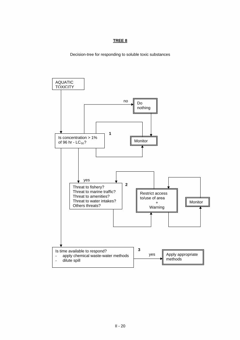
Decision-tree for responding to soluble toxic substances
II - 20
no 1 yes 2 3 yes
Is concentration > 1% of 96 hr - LC50?
Do nothing
Threat to fishery? Threat to marine traffic? Threat to amenities? Threat to water intakes? Others threats?
Restrict access to/use of area
+ Warning
Is time available to respond? - apply chemical waste-water methods - dilute spill
Monitor
Apply appropriate methods
Monitor
AQUATIC TOXICITY

THINK DETAILS FOR TREE 8
1. Is the concentration > 1% of 96hr-LC50?
The so-called “do-nothing” action in reality means a great deal and involves monitoring the situation as it evolves during the incident. As a rule of thumb, when the concentration of the spilled substance in water is greater than 1% of the 96hr-LC50, the substance spilled concentration may cause immediate damage to marine living resources. In cases where the scientific data in the literature exist for more than one aquatic species, it is best that the lowest LC50 (i.e. the value showing the highest acute toxicity) be considered for evaluating the hazard. If possible, data from the following three tests should be obtained and the lowest value taken: - a 96hr LC50 fish test; - a 48-96hr LC50/EC50 crustacean test; and - a 72 hr or EC50 microalgal growth inhibition test.
The following table provides significance to aquatic toxicity data:
LC50 (mg/l) Significance >1000 100-1000 10-100 1-10 0.1-1 0.01-0.1 <0.01
non-toxic practically non-toxic slightly toxic moderately toxic highly toxic very highly toxic extremely toxic
The LC50 for fish can be estimated using the relationship: Log LC50 = -0.94 log Pow + 0.94 log (0.000068Pow + 1) - 1.25 where log Pow is the logarithm to base 10 of the octanol-water partition coefficient (Kow) and
can be found as a physical-chemical datum in material data sheets for chemicals or other sources of information on the chemical spilled.
The log Pow is also indicative of an organic chemical’s propensity for bioconcentration by
aquatic organisms and is used as a surrogate for the bioconcentration factor (BCF) which provides definitive information on the potential of a substance to bioaccumulate. The following table provides significance to log Pow and BCF values:
* log Pow < 1 or ca.7 No potential to bioaccumulate no measurable BCF log Pow 1 - < 2 Very low potential to bioaccumulate BCF 1 - < 10 log Pow 2 - < 3 Low potential to bioaccumulate BCF 10 - < 100 log Pow 3 - < 4 Moderate potential to bioaccumlate BCF 100 - < 500 log Pow 4 - < 5 High potential to bioaccumulate BCF 500 - < 4000 Log Pow > 5 Very high potential to bioaccumulate BCF > 4000 * Note: In general, when evaluating the potential to bioaccumulate, the BCF data should overrule log Pow data; substances with high log Pow (ca.> 7) are presumed to be too insoluble in water to bioaccumulate; substance with high molecular weights 700 - > 1000 are assumed not to accumulate.
II - 21
2. Is there a threat to users of the sea?
As a general rule, access to the casualty area should be limited and activities in the area restricted. Restrictions should be lifted once the area is declared safe. A spill involving a dissolver will disperse through the water column and it is important to map the extent of the dispersion. Detecting the extent of dispersion is done by a monitoring campaign involving a programme of marine life, water and sediment sampling and analyses. Analyses of dissolved chemicals in water can be done by different types of portable instruments, spectrometers, conductivity meters, fluorometers. In all cases, the background level of the uncontaminated sea-water must be known for comparison purposes. Depending on availability, a monitoring campaign may also involve elaborate instrumentation and equipment be placed onboard a vessel to allow continuous analysis of certain hydrobiological parameters.
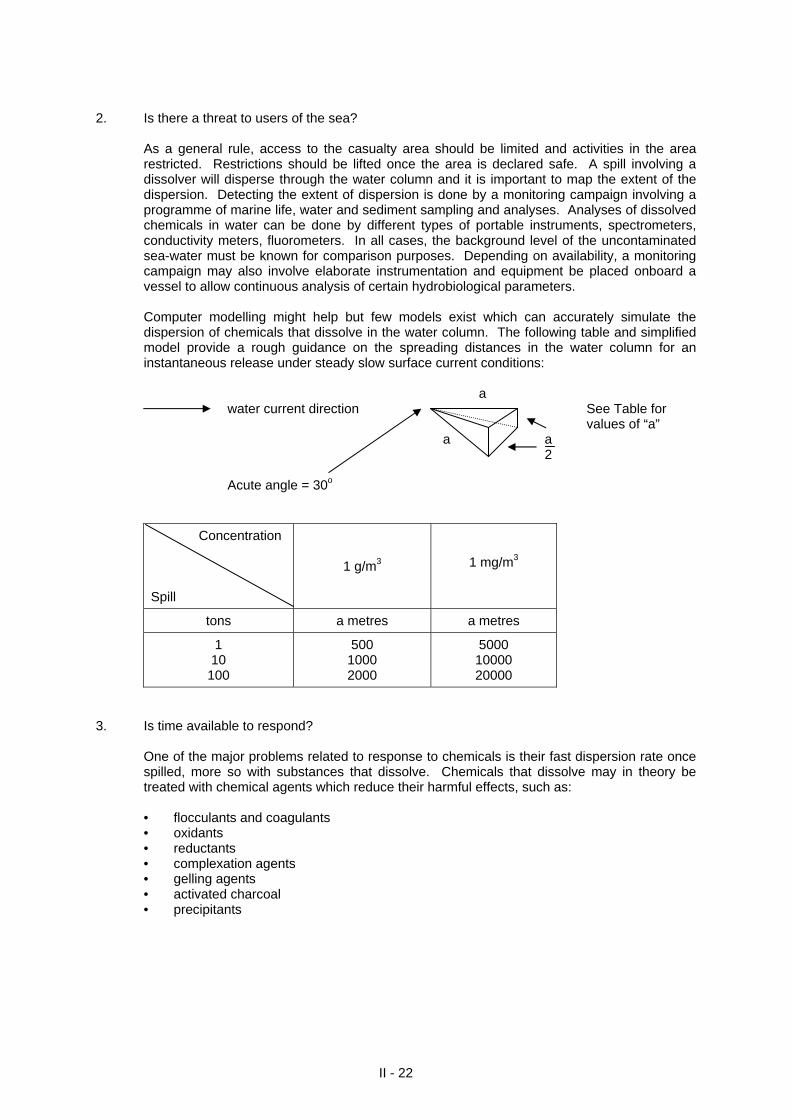
Computer modelling might help but few models exist which can accurately simulate the
dispersion of chemicals that dissolve in the water column. The following table and simplified model provide a rough guidance on the spreading distances in the water column for an instantaneous release under steady slow surface current conditions:
a water current direction See Table for values of “a”
II - 22
a a 2 Acute angle = 30o
Concentration Spill
1 g/m3
1 mg/m3
tons a metres a metres
1 10
100
500 1000 2000
5000 10000 20000
3. Is time available to respond?
One of the major problems related to response to chemicals is their fast dispersion rate once spilled, more so with substances that dissolve. Chemicals that dissolve may in theory be treated with chemical agents which reduce their harmful effects, such as: • flocculants and coagulants • oxidants • reductants • complexation agents • gelling agents • activated charcoal • precipitants
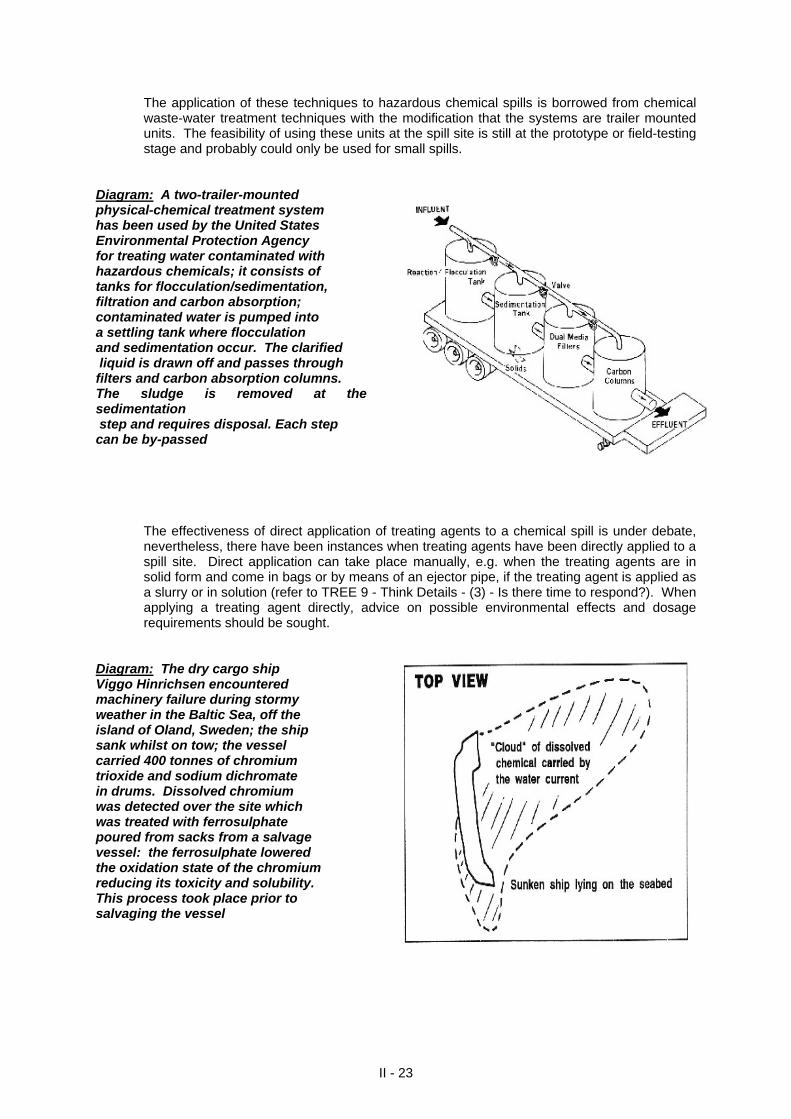
The application of these techniques to hazardous chemical spills is borrowed from chemical waste-water treatment techniques with the modification that the systems are trailer mounted units. The feasibility of using these units at the spill site is still at the prototype or field-testing stage and probably could only be used for small spills.
II - 23
Diagram: A two-trailer-mounted physical-chemical treatment system has been used by the United States Environmental Protection Agency for treating water contaminated with hazardous chemicals; it consists of tanks for flocculation/sedimentation, filtration and carbon absorption; contaminated water is pumped into a settling tank where flocculation and sedimentation occur. The clarified liquid is drawn off and passes through filters and carbon absorption columns. The sludge is removed at the sedimentation step and requires disposal. Each step can be by-passed The effectiveness of direct application of treating agents to a chemical spill is under debate,
nevertheless, there have been instances when treating agents have been directly applied to a spill site. Direct application can take place manually, e.g. when the treating agents are in solid form and come in bags or by means of an ejector pipe, if the treating agent is applied as a slurry or in solution (refer to TREE 9 - Think Details - (3) - Is there time to respond?). When applying a treating agent directly, advice on possible environmental effects and dosage requirements should be sought.
Diagram: The dry cargo ship Viggo Hinrichsen encountered machinery failure during stormy weather in the Baltic Sea, off the island of Oland, Sweden; the ship sank whilst on tow; the vessel carried 400 tonnes of chromium trioxide and sodium dichromate in drums. Dissolved chromium was detected over the site which was treated with ferrosulphate poured from sacks from a salvage vessel: the ferrosulphate lowered the oxidation state of the chromium reducing its toxicity and solubility. This process took place prior to salvaging the vessel
TREE 9
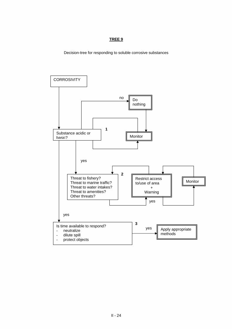
Decision-tree for responding to soluble corrosive substances
II - 24
no 1 yes 2 yes yes 3 yes
CORROSIVITY
Substance acidic or basic?
Do nothing
Threat to fishery? Threat to marine traffic? Threat to water intakes? Threat to amenities? Other threats?
Restrict access to/use of area
+ Warning
Is time available to respond? - neutralize - dilute spill - protect objects
Monitor
Apply appropriate methods
Monitor
THINK DETAILS FOR TREE 9 1. Is the substance acidic or basic? The so-called “do-nothing” action in reality means a great deal and involves monitoring the
situation as it evolves during the incident. Certain materials, e.g. sulphuric acid, caustic soda, when dissolved in water have what is
called a positive heat of solution, meaning that they generate heat when mixing. General substances in this category (strong acids or bases) also generate large amounts of fumes when in contact with water or even moisture in air. These fumes usually consist of acidic or basic vapours which are highly irritating, corrosive and heavier than air. The acidic or basic nature of a substance is measured by its pH which is an expression of the concentration of the hydrogen ion on a logarithmic scale of 1 to 14. A pH of 1 is extremely acidic, a pH of 14 is extremely basic and a pH of 7 is neutral. A change of 1 unit, e.g. pH change of 2 to 3, means a 10-fold increase in hydrogen ion concentration.
2. Is there a threat to users of the sea? As a general rule, access to the casualty area should be limited and activities in the area
restricted. Restrictions should be lifted once the area is declared safe. The size of the risk area can be estimated by sampling and monitoring and/or using dispersion models (refer to TREE 8 - Think Details (2) - Is there a threat to users of the sea?). Monitoring of acids or bases can be done with a pH meter or with pH or indicator. In the latter case, the paper is impregnated with an indicator which changes colour on contact with the water sample. The resulting colour is compared with the colour reflecting pH value.
3. Is time available to respond? One method of dealing with spilled acids or bases is by neutralization. Neutralization is the
process of applying acids or bases to a spill to form a neutral salt. Strong bases or acids are the most economical neutralization since only small amounts are
required to be applied. However, application of strong neutralizers makes it difficult to control the neutralization process and can result in extreme pH levels due to overdosing (i.e. outside the range of 6 - 9) which may be more hazardous than the original spilled material.
Sodium dehydrogen phosphate (NaH2PO4) and sodium bicarbonate (NaHCO3) have been
shown to be the most promising neutralizing agents for basic or alkaline and acidic spills respectively. In theory, it should be possible to add, together with the neutralizing agent, a pH indicator. This must have the chemical characteristic of undergoing a perceptible colour change. On addition of the neutralizing agent - pH indicator mixture, the pH indicator should exhibit the appropriate colour change for the pH change. Bromothymol blue might be a suitable pH indicator.
Acids Compounds reacting with water to give acids
Acetic Acid Acrylic Acid Formic Acid Hydrochloric Acid Hydrofluoric Acid Hydrogen Chloride Sulphuric Acid (spent) Hydrogen Fluoride Nitric Acid Oxalic Acid Phosphoric Acid Sulphuric Acid
Acetic Anhydride Aluminium Chloride Benzoyl Chloride Bromine Chlorosulphonic Acid Maleic Anhydride Nitrogen Tetroxide Nitrosyl Chloride Oleum Phosphorus Oxychloride Phosphorus Pentasulphide Polyphosphoric Acid Sulphur Monochloride Sulphuryl Chloride Titanium Tetrachloride
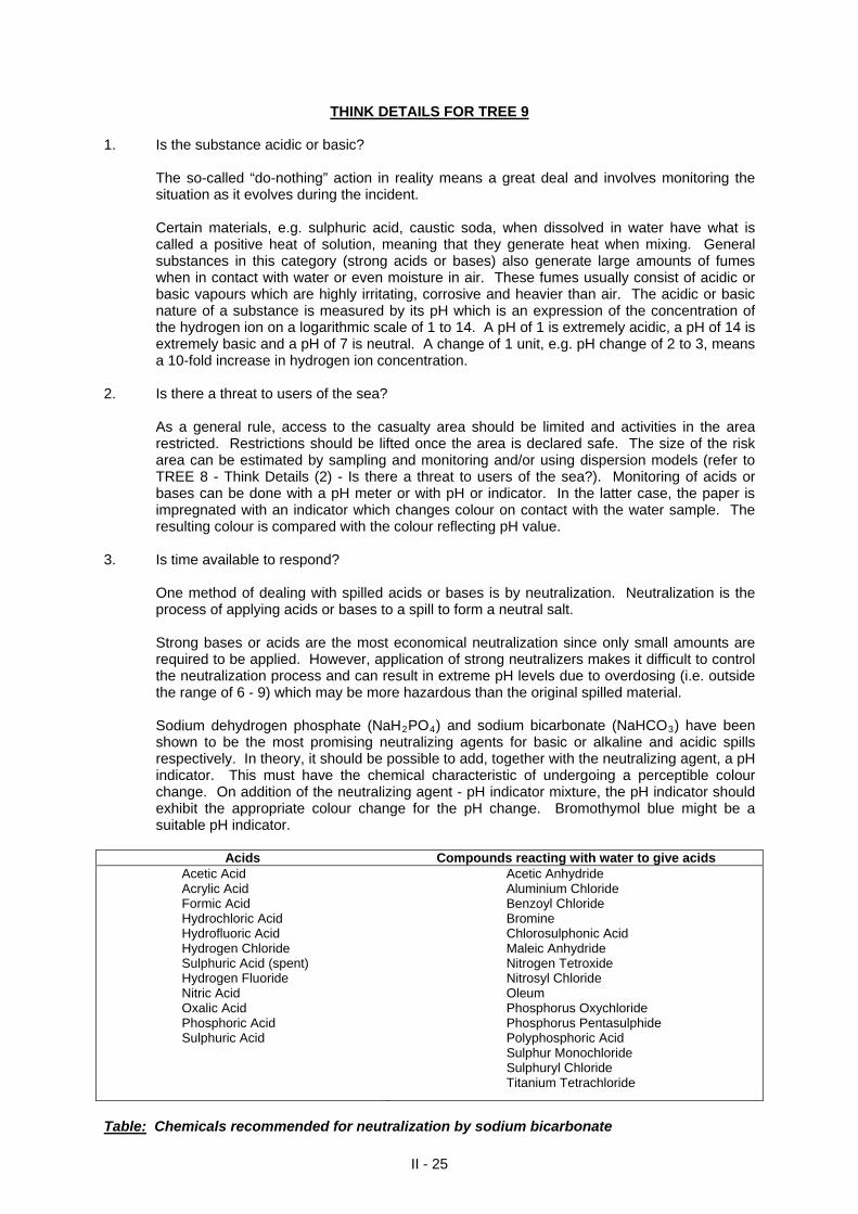
Table: Chemicals recommended for neutralization by sodium bicarbonate
II - 25
Bases Compounds reacting with water to give bases Aminoethylethanolamine Ammonium Hydroxide Caustic Potash Solution Caustic Soda Solution Cyclohexylamine Diethynolamine Diethylamine Diethylenetriamine Diisopropanolamine 1,1-Dimethylhydrazine Ethylenediamine Hydrazine Monoethanolamine Monoisopropanolamine Morpholine Potassium Hydroxide Sodium Hydroxide Triethanolamine Triethylamine Triethylenetetramine Trimethylamine Hexamethylenediamine
Sodium Sodium Amide Sodium Hydride Anhydrous Ammonia Ethyleneimine Lithium Aluminium Hydride
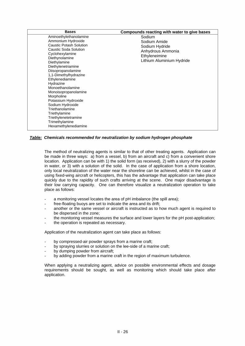
Table: Chemicals recommended for neutralization by sodium hydrogen phosphate The method of neutralizing agents is similar to that of other treating agents. Application can
be made in three ways: a) from a vessel, b) from an aircraft and c) from a convenient shore location. Application can be with 1) the solid form (as received), 2) with a slurry of the powder in water, or 3) with a solution of the solid. In the case of application from a shore location, only local neutralization of the water near the shoreline can be achieved, whilst in the case of using fixed-wing aircraft or helicopters, this has the advantage that application can take place quickly due to the rapidity of such crafts arriving at the scene. One major disadvantage is their low carrying capacity. One can therefore visualize a neutralization operation to take place as follows:
- a monitoring vessel locates the area of pH imbalance (the spill area); - free-floating buoys are set to indicate the area and its drift; - another or the same vessel or aircraft is instructed as to how much agent is required to
be dispersed in the zone; - the monitoring vessel measures the surface and lower layers for the pH post-application; - the operation is repeated as necessary.
Application of the neutralization agent can take place as follows:
- by compressed-air powder sprays from a marine craft; - by spraying slurries or solution on the lee-side of a marine craft; - by dumping powder from aircraft; - by adding powder from a marine craft in the region of maximum turbulence.
When applying a neutralizing agent, advice on possible environmental effects and dosage
requirements should be sought, as well as monitoring which should take place after application.
II - 26
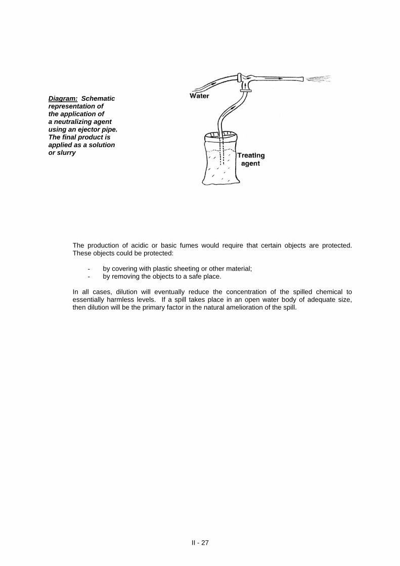
Diagram: Schematic representation of the application of a neutralizing agent using an ejector pipe. The final product is applied as a solution or slurry The production of acidic or basic fumes would require that certain objects are protected.
These objects could be protected:
- by covering with plastic sheeting or other material; - by removing the objects to a safe place.
In all cases, dilution will eventually reduce the concentration of the spilled chemical to
essentially harmless levels. If a spill takes place in an open water body of adequate size, then dilution will be the primary factor in the natural amelioration of the spill.
II - 27
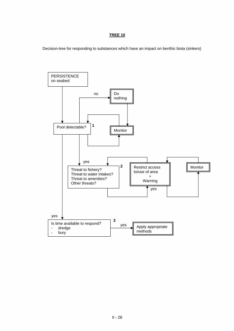
TREE 10
Decision-tree for responding to substances which have an impact on benthic biota (sinkers)
II - 28
no 1 yes 2 yes yes 3
Threat to fishery? Threat to water intakes? Threat to amenities? Other threats?
MonitorRestrict access to/use of area
+ Warning
Pool detectable?
Do nothing
Monitor
PERSISTENCE on seabed
yes Apply appropriate methods
Is time available to respond? - dredge - bury
THINK DETAILS FOR TREE 10
1. Is the pool detectable?
The so-called “do-nothing” action in reality means a great deal and involves monitoring the situation as it evolves during the incident. A liquid pool or solid bulk material can cause blanketing of the sea floor as well as anaerobic conditions harming the benthic ecosystem. A spill involving a sinker will spread over the sea floor. It is therefore important to map the extent of the spread. Detecting the extent of spread is done by sampling the water, interstitial waters, sediments and benthic organisms followed by chemical analysis. Sinking substances could also be slightly soluble due to the large quantities of water surrounding the substance.
2. Is there a threat to users of the sea?
As a general rule, access to the casualty area should be limited and activities in the area restricted. Restrictions should be lifted once the area is declared safe. The size of the risk area is determined by the extent of contamination noted (see 1 above). Safe distances are then determined by applying a safety factor to the exterior limit of the contaminated area.
3. Is time available to respond?
Dredging, which is a method for the removal of underwater material, can be used as a response method for substances that are heavier than water and considered insoluble. Three different categories of dredges can be used: mechanical, hydraulic or pneumatic.
Category Type
Mechanical dredges Mechanical dredges such as grab (clamshell), dipper or bucket ladder type are designed for the removal of hard or soft material and normally are not self-propelled; it is not advisable to use such dredges since the devices used for excavating tend to disturb the sediment to the extent that contaminated sediment is scattered.
Hydraulic dredges Hydraulic dredges remove contaminated sediment in slurry form through nozzles connected to suction pumps; it is not advisable to use hydraulic dredges if they are used since they too tend to scatter the chemicals during operations. Sometimes certain devices (cutterheads) are attached to the nozzles during routine dredging operations. These devices should be removed when used for collecting sunken substances since, like the buckets or grabs on mechanical dredges, these tend to cause significant sediment disturbance scattering the chemical.
Airlift dredges Pneumatic dredges are hydraulic pipeline systems that use a compressed air-operated pump; airlift dredge systems have been used with some success in accidents. Airlift dredges are hydraulic systems that have pipes extending from surface to bottom and use a compressed air-operated pump to inject compressed air at the intake which helps to push the contaminated sediment upwards. These systems have been used with some sources in chemical accidents. Sometimes these devices are small enough to be manipulated by a diver in which case the major drawback is contaminant exposure for the operator.
II - 29
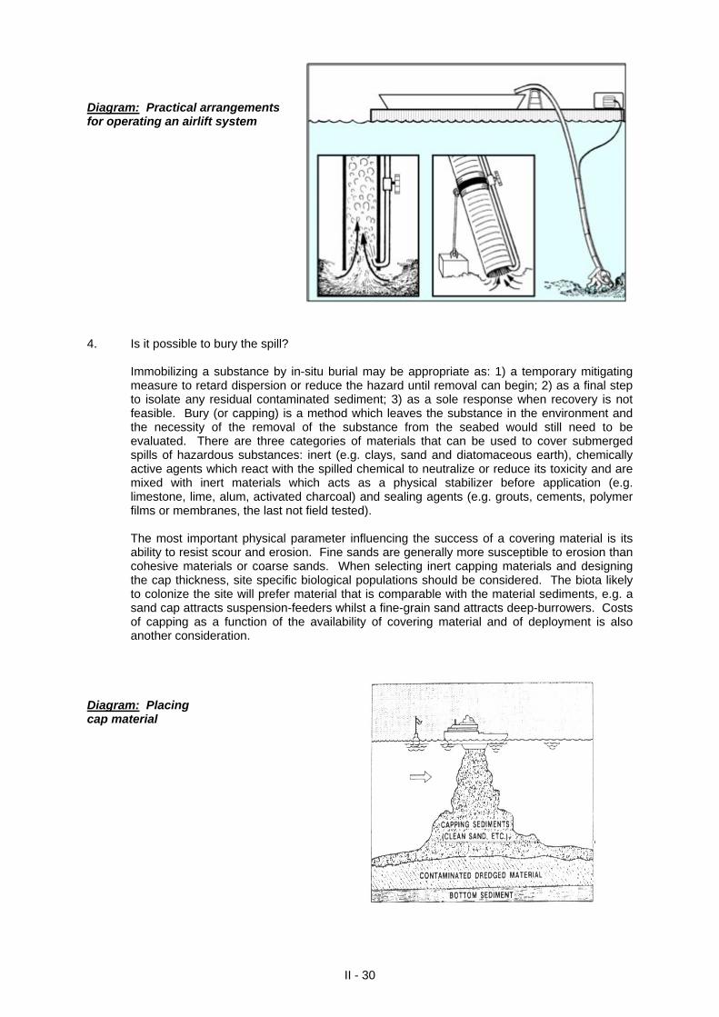
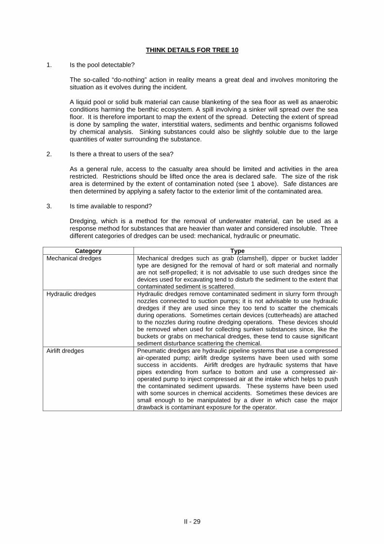
Diagram: Practical arrangements for operating an airlift system 4. Is it possible to bury the spill?
Immobilizing a substance by in-situ burial may be appropriate as: 1) a temporary mitigating measure to retard dispersion or reduce the hazard until removal can begin; 2) as a final step to isolate any residual contaminated sediment; 3) as a sole response when recovery is not feasible. Bury (or capping) is a method which leaves the substance in the environment and the necessity of the removal of the substance from the seabed would still need to be evaluated. There are three categories of materials that can be used to cover submerged spills of hazardous substances: inert (e.g. clays, sand and diatomaceous earth), chemically active agents which react with the spilled chemical to neutralize or reduce its toxicity and are mixed with inert materials which acts as a physical stabilizer before application (e.g. limestone, lime, alum, activated charcoal) and sealing agents (e.g. grouts, cements, polymer films or membranes, the last not field tested).
The most important physical parameter influencing the success of a covering material is its ability to resist scour and erosion. Fine sands are generally more susceptible to erosion than cohesive materials or coarse sands. When selecting inert capping materials and designing the cap thickness, site specific biological populations should be considered. The biota likely to colonize the site will prefer material that is comparable with the material sediments, e.g. a sand cap attracts suspension-feeders whilst a fine-grain sand attracts deep-burrowers. Costs of capping as a function of the availability of covering material and of deployment is also another consideration.
Diagram: Placing cap material
II - 30
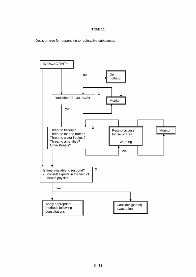
TREE 11
Decision-tree for responding to radioactive substances
II - 31
no 1 yes 2 yes
Radiation 25 - 30 µSv/hr
Do nothing
Threat to fishery? Threat to marine traffic? Threat to water intakes? Threat to amenities? Other threats?
MonitorRestrict access to/use of area
+ Warning
Monitor
RADIOACTIVITY
3 yes Consider (partial)
evacuation
Apply appropriate methods following consultations
Is time available to respond? - consult experts in the field of
health physics
II - 32
THINK DETAILS FOR TREE 11
1. Is the concentration > 25 - 30 µSv/hr?
The so-called “do-nothing” action in reality means a great deal and involves monitoring the situation as it evolves during the incident. Radioactivity is the spontaneous disintegration of certain nuclei accompanied by the emission of the alpha particles (helium nuclei), beta-particles (electrons), or gamma-radiation (short-wave electromagnetic waves which have similar properties to x-rays). Since radiation is the general term used to express the emission and propagation of energy through space or through some other medium, it is also extended to include emission of sub-atomic particles as alpha particles, beta particles and gamma rays from radioactive sources. The interaction of certain kinds of radiation with matter results in ionization. The damage to living tissue inflicted by radiation is a consequence of this ionization whilst all instruments for radioactivity measurements depend on this property. The amount of damage inflicted depends on the type and energy of radiation. Gamma rays are the most penetrating. Radiation is measured by a special unit, a unit not of quantity, but of effect of radiation. This is the Seivert (Sv) or the Roentgen (rem; 10 mSv = 1 rem) which are units of absorbed dose of radiation. If the radiation is detected above background levels (25 µSv/h - 30 µSv/h equivalent to 2.5 mrem/h - 3.0 mrem/hr), this signifies the presence of possible radioactive sources and more monitoring is advisable. At values of > 100 µSv/hr, there is potential of a radiation hazard and evacuation should be considered. Monitoring should only continue on advice of a health physicist.
2. Is there a threat to users of the sea? As a general rule, access to the casualty area is limited and activities in the area restricted. Restrictions are lifted once the area is declared safe. The size of the risk area can be determined by monitoring. It is important that proper radiation detection equipment be available to determine the type of radiation hazard present if it is decided to monitor. Generally, radiameters cannot detect all types of radiation.
3. Is there a possibility to protect from external sources of radiation?
Exposure from an external source (such as an intact package of radioactive material) can be reduced by increasing the distance from the source, reducing time in the vicinity of the sources; providing intervening shielding between you and the source.
SECTION III
CLASSIFYING CHEMICALS SPILLED AT SEA
A classification system has been developed to classify substances according to their behaviour when spilled at sea. The main principle is
the categorization of a chemical release as an evaporator, floater, dissolver and sinker so that chemicals belonging to the same group showing similar physical behaviour in water can be responded to by using similar methods.
Some chemicals may show special patterns of behaviour when spilled. Sources: 1) CEDRE’s Notes to MEDEXPOL 1998. 2) Helcom Combating Manual, Volume III. 3) Swedish Coast Guard Notes on Chemicals and Dangerous Goods. 4) IMO Chemical Pollution Manual, Section 1 (MEPC 42/7/Add.2).
CLASSIFICATION BY BEHAVIOUR This classification is based upon the distribution of chemicals in air, water surface, water column or on the seabed. By dividing chemical substances into groups, it should be easier to develop more appropriate combating methods. This classification system divides chemical substances into four main categories and is based on the work done within the Bonn Agreement and the Helsinki Commission:
evaporators (E); floaters (F);
dissolvers (D);
sinkers (S).
Because chemicals can also belong to several other categories, each main category is divided further. For example, a substance may float on the water surface and, at the same time, evaporate and/or dissolve. The physical properties used for the categorization are as follows:
state of the substance: gas, liquid, solid; density compared to sea-water;
partial vapour pressure;
solubility;
density relative to air.
CRITERIA FOR THE CLASSIFICATION
The physical state of the substance has been set at 20oC. The evaluation of the 300 most commonly transported chemicals in the North Sea shows that there is no major difference in behaviour over the temperature range 5 - 20oC.
The density relative to sea-water determines whether a substance floats on the water surface.
The relative density of sea-water has been taken as 1.03 at 20oC.
The vapour pressure has been set to 0.3 kPa because with a vapour pressure less than 0.3 kPa, substances have been considered to be non-evaporators. At the other end of the scale, the criterion for rapid evaporation (disappearance of 1000 m3 of a chemical within one hour) is a vapour pressure of 3 kPa (23 mm Hg). Substances with a vapour pressure higher than 100 kPa (760 mm Hg) are considered true gases.
Solubility. Criteria are different according to the physical state of the substance. Liquids with
a solubility less than 0.1% can be disregarded with respect to the dissolution process. With a solubility higher than 5%, the process of dissolution becomes the most significant process. For solids, the limits to ignore or to consider the process of dissolution are respectively 10% and 100%.
Density relative to air. Gases or vapours with a density relative to air > 1.0 will remain at the
water surface. The density relative to air has been taken as 1.0 at 20oC.
III - 1
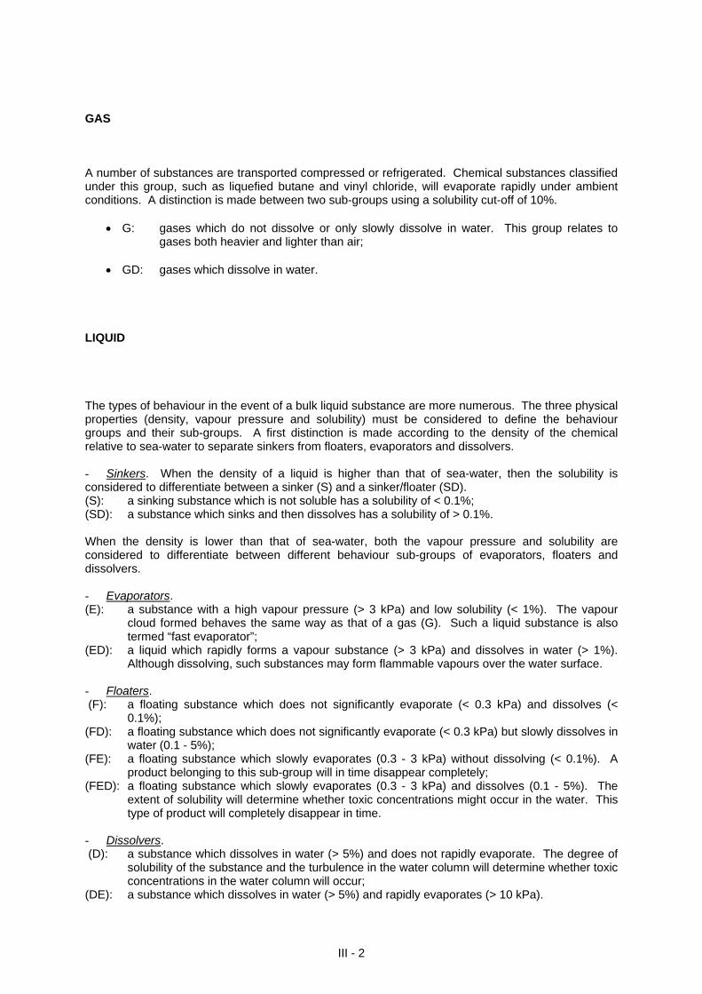
GAS A number of substances are transported compressed or refrigerated. Chemical substances classified under this group, such as liquefied butane and vinyl chloride, will evaporate rapidly under ambient conditions. A distinction is made between two sub-groups using a solubility cut-off of 10%. G: gases which do not dissolve or only slowly dissolve in water. This group relates to
gases both heavier and lighter than air; GD: gases which dissolve in water. LIQUID The types of behaviour in the event of a bulk liquid substance are more numerous. The three physical properties (density, vapour pressure and solubility) must be considered to define the behaviour groups and their sub-groups. A first distinction is made according to the density of the chemical relative to sea-water to separate sinkers from floaters, evaporators and dissolvers. - Sinkers. When the density of a liquid is higher than that of sea-water, then the solubility is considered to differentiate between a sinker (S) and a sinker/floater (SD). (S): a sinking substance which is not soluble has a solubility of < 0.1%; (SD): a substance which sinks and then dissolves has a solubility of > 0.1%. When the density is lower than that of sea-water, both the vapour pressure and solubility are considered to differentiate between different behaviour sub-groups of evaporators, floaters and dissolvers. - Evaporators. (E): a substance with a high vapour pressure (> 3 kPa) and low solubility (< 1%). The vapour
cloud formed behaves the same way as that of a gas (G). Such a liquid substance is also termed “fast evaporator”;
(ED): a liquid which rapidly forms a vapour substance (> 3 kPa) and dissolves in water (> 1%). Although dissolving, such substances may form flammable vapours over the water surface.
- Floaters. (F): a floating substance which does not significantly evaporate (< 0.3 kPa) and dissolves (<
0.1%); (FD): a floating substance which does not significantly evaporate (< 0.3 kPa) but slowly dissolves in
water (0.1 - 5%); (FE): a floating substance which slowly evaporates (0.3 - 3 kPa) without dissolving (< 0.1%). A
product belonging to this sub-group will in time disappear completely; (FED): a floating substance which slowly evaporates (0.3 - 3 kPa) and dissolves (0.1 - 5%). The
extent of solubility will determine whether toxic concentrations might occur in the water. This type of product will completely disappear in time.
- Dissolvers. (D): a substance which dissolves in water (> 5%) and does not rapidly evaporate. The degree of
solubility of the substance and the turbulence in the water column will determine whether toxic concentrations in the water column will occur;
(DE): a substance which dissolves in water (> 5%) and rapidly evaporates (> 10 kPa).
III - 2
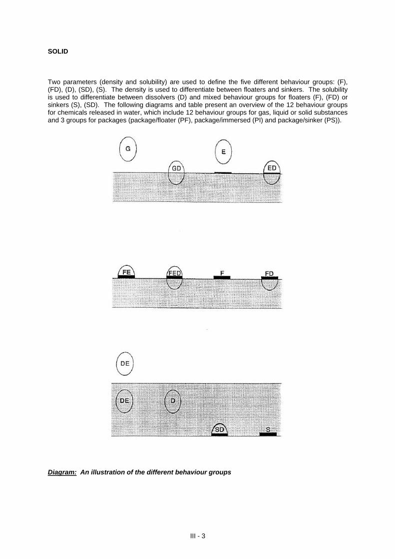
SOLID Two parameters (density and solubility) are used to define the five different behaviour groups: (F), (FD), (D), (SD), (S). The density is used to differentiate between floaters and sinkers. The solubility is used to differentiate between dissolvers (D) and mixed behaviour groups for floaters (F), (FD) or sinkers (S), (SD). The following diagrams and table present an overview of the 12 behaviour groups for chemicals released in water, which include 12 behaviour groups for gas, liquid or solid substances and 3 groups for packages (package/floater (PF), package/immersed (PI) and package/sinker (PS)).
Diagram: An illustration of the different behaviour groups
III - 3
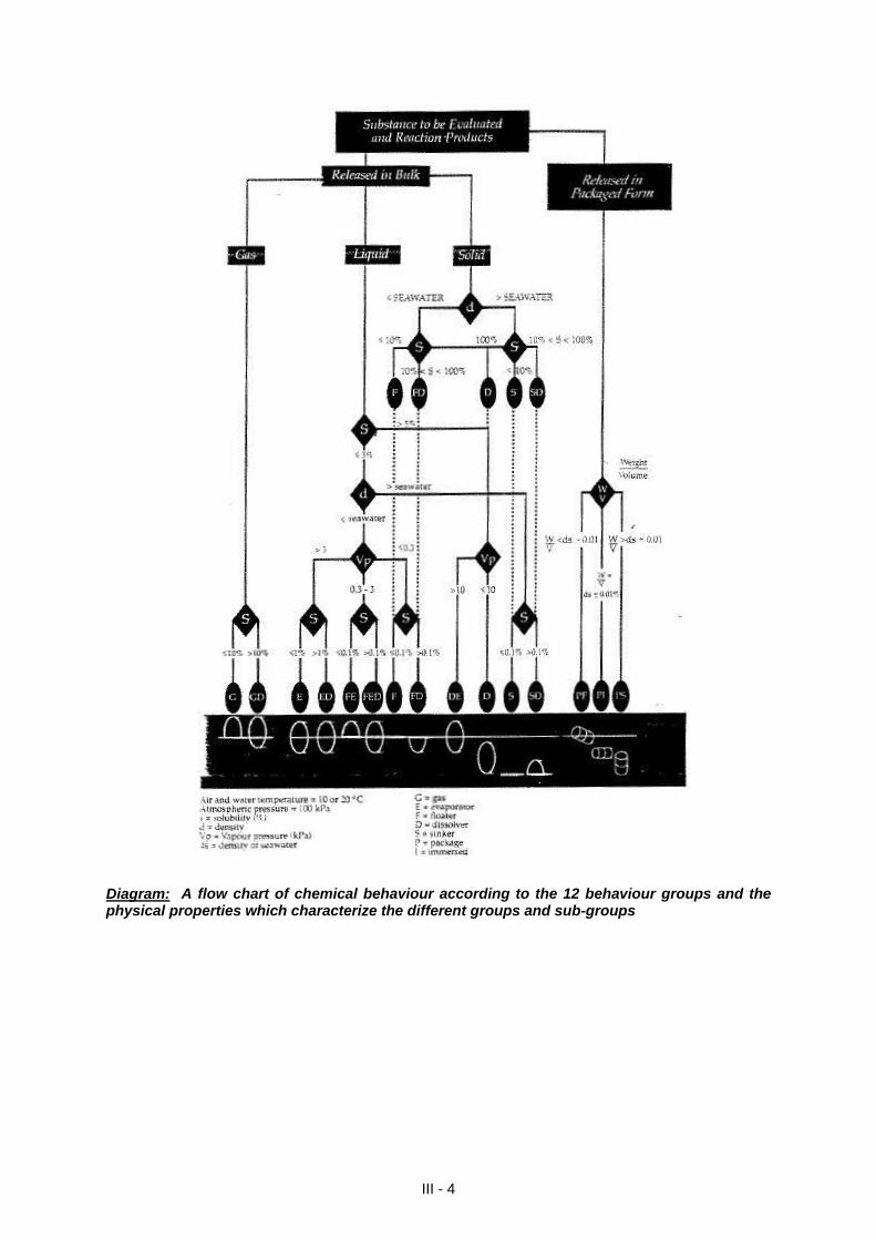
Diagram: A flow chart of chemical behaviour according to the 12 behaviour groups and the physical properties which characterize the different groups and sub-groups
III - 4
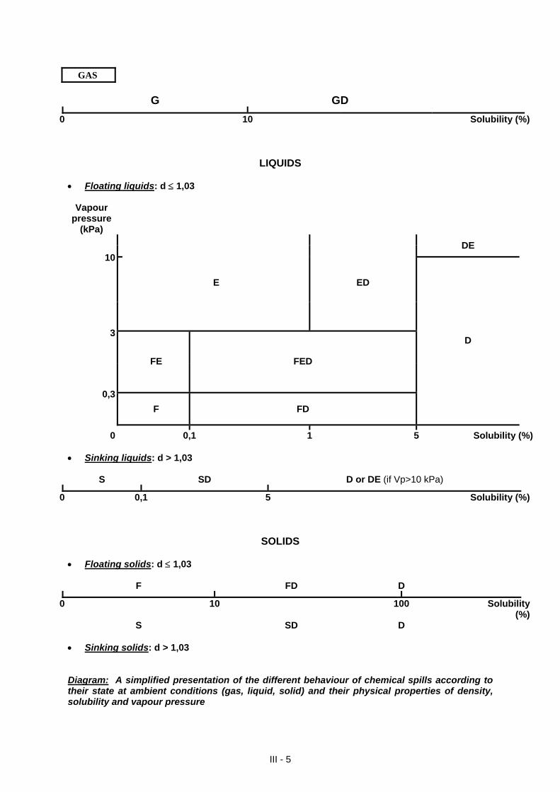
GAS
G GD
0 10 Solubility (%)
LIQUIDS Floating liquids: d 1,03
Vapour pressure
(kPa)
DE 10
E ED
3
FE FED
0,3
F FD
D
0 0,1 1 5 Solubility (%) Sinking liquids: d > 1,03
S SD D or DE (if Vp>10 kPa)
0 0,1 5 Solubility (%)
SOLIDS Floating solids: d 1,03
F FD D
0 10 100 Solubility (%)
S SD D Sinking solids: d > 1,03 Diagram: A simplified presentation of the different behaviour of chemical spills according to their state at ambient conditions (gas, liquid, solid) and their physical properties of density, solubility and vapour pressure
III - 5
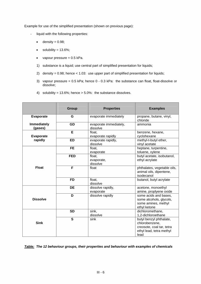
Example for use of the simplified presentation (shown on previous page):
- liquid with the following properties:
density = 0.98;
solubility = 13.6%;
vapour pressure = 0.5 kPa.
1) substance is a liquid; use central part of simplified presentation for liquids;
2) density = 0.98; hence < 1.03: use upper part of simplified presentation for liquids;
3) vapour pressure = 0.5 kPa; hence 0 - 0.3 kPa: the substance can float, float-dissolve or dissolve;
4) solubility = 13.6%; hence > 5.0%: the substance dissolves.
Group
Properties
Examples
G evaporate immediately propane, butane, vinyl, chloride
Evaporate
Immediately (gases)
GD evaporate immediately, dissolve
ammonia
E float, evaporate rapidly
benzene, hexane, cyclohexane
Evaporate
rapidly
ED evaporate rapidly, dissolve
methyl-t-butyl ether, vinyl acetate
FE float, evaporate
heptane, turpentine, toluene, xylene
FED float, evaporate, dissolve
butyl acetate, isobutanol, ethyl acrylate
F float phthalates, vegetable oils, animal oils, dipentene, isodecanol
Float
FD float, dissolve
butanol, butyl acrylate
DE dissolve rapidly, evaporate
acetone, monoethyl amine, proplyene oxide
Dissolve D dissolve rapidly some acids and bases,
some alcohols, glycols, some amines, methyl ethyl ketone
SD sink, dissolve
dichloromethane, 1,2-dichloroethane
Sink S sink butyl benzyl phthalate,
chlorobenzene, creosote, coal tar, tetra ethyl lead, tetra methyl lead
Table: The 12 behaviour groups, their properties and behaviour with examples of chemicals
III - 6
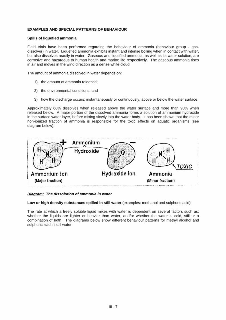
EXAMPLES AND SPECIAL PATTERNS OF BEHAVIOUR Spills of liquefied ammonia Field trials have been performed regarding the behaviour of ammonia (behaviour group - gas-dissolver) in water. Liquefied ammonia exhibits instant and intense boiling when in contact with water, but also dissolves readily in water. Gaseous and liquefied ammonia, as well as its water solution, are corrosive and hazardous to human health and marine life respectively. The gaseous ammonia rises in air and moves in the wind direction as a dense white cloud. The amount of ammonia dissolved in water depends on:
1) the amount of ammonia released; 2) the environmental conditions; and
3) how the discharge occurs; instantaneously or continuously, above or below the water surface.
Approximately 60% dissolves when released above the water surface and more than 90% when released below. A major portion of the dissolved ammonia forms a solution of ammonium hydroxide in the surface water layer, before mixing slowly into the water body. It has been shown that the minor non-ionized fraction of ammonia is responsible for the toxic effects on aquatic organisms (see diagram below).
Diagram: The dissolution of ammonia in water Low or high density substances spilled in still water (examples: methanol and sulphuric acid) The rate at which a freely soluble liquid mixes with water is dependent on several factors such as: whether the liquids are lighter or heavier than water, and/or whether the water is cold, still or a combination of both. The diagrams below show different behaviour patterns for methyl alcohol and sulphuric acid in still water.
III - 7
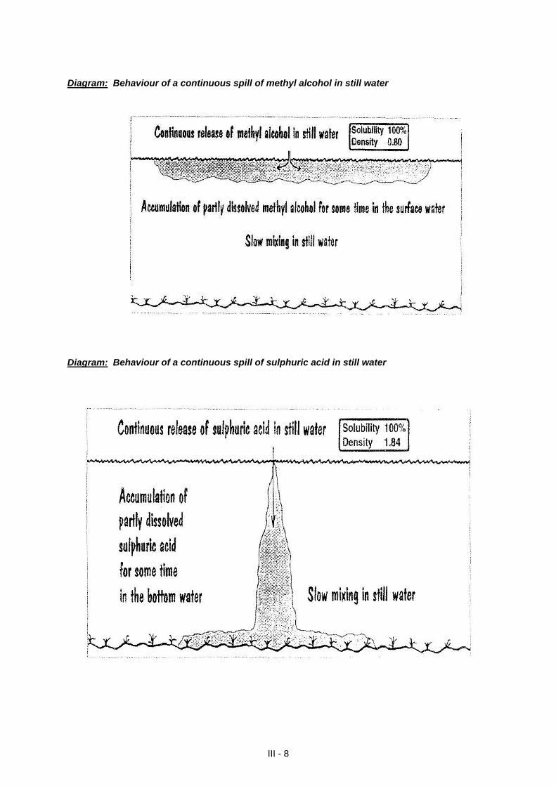
Diagram: Behaviour of a continuous spill of methyl alcohol in still water Diagram: Behaviour of a continuous spill of sulphuric acid in still water
III - 8
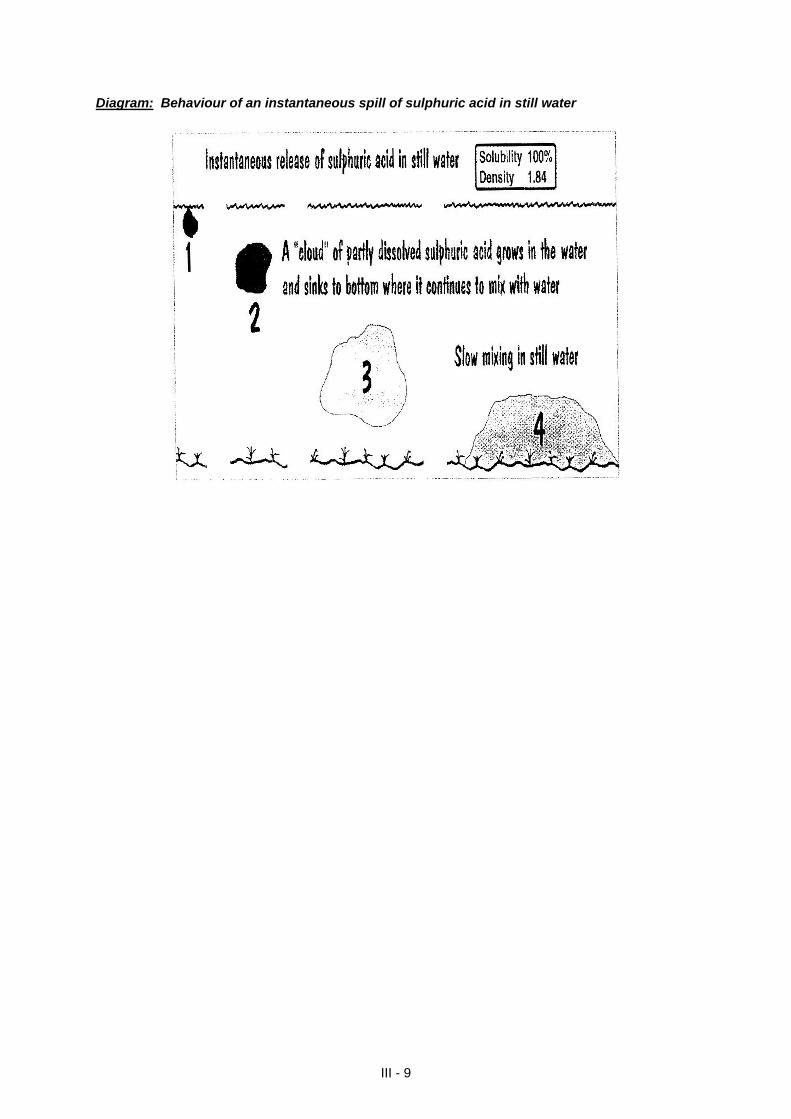
Diagram: Behaviour of an instantaneous spill of sulphuric acid in still water
III - 9
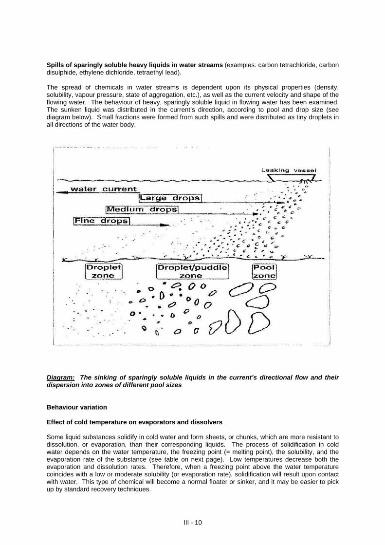
Spills of sparingly soluble heavy liquids in water streams (examples: carbon tetrachloride, carbon disulphide, ethylene dichloride, tetraethyl lead). The spread of chemicals in water streams is dependent upon its physical properties (density, solubility, vapour pressure, state of aggregation, etc.), as well as the current velocity and shape of the flowing water. The behaviour of heavy, sparingly soluble liquid in flowing water has been examined. The sunken liquid was distributed in the current’s direction, according to pool and drop size (see diagram below). Small fractions were formed from such spills and were distributed as tiny droplets in all directions of the water body.
Diagram: The sinking of sparingly soluble liquids in the current’s directional flow and their dispersion into zones of different pool sizes Behaviour variation Effect of cold temperature on evaporators and dissolvers Some liquid substances solidify in cold water and form sheets, or chunks, which are more resistant to dissolution, or evaporation, than their corresponding liquids. The process of solidification in cold water depends on the water temperature, the freezing point (= melting point), the solubility, and the evaporation rate of the substance (see table on next page). Low temperatures decrease both the evaporation and dissolution rates. Therefore, when a freezing point above the water temperature coincides with a low or moderate solubility (or evaporation rate), solidification will result upon contact with water. This type of chemical will become a normal floater or sinker, and it may be easier to pick up by standard recovery techniques.
III - 10

The first four chemicals listed in the first table have very low values of both solubility and vapour pressure. Their behaviour will not alter significantly when they change from liquid to the solid state upon contact with water.
III - 11
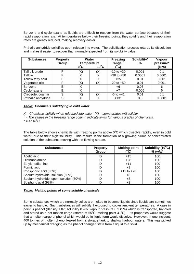
Benzene and cyclohexane as liquids are difficult to recover from the water surface because of their rapid evaporation rate. At temperatures below their freezing points, they solidify and their evaporation rates are greatly reduced, making recovery easier. Phthalic anhydride solidifies upon release into water. The solidification process retards its dissolution and makes it easier to recover than normally expected from its solubility value.
Substances Property Group
Water Temperature
0oC 10oC
Freezing range †
(oC)
Solubility*
% Vapour
pressure* (kPa)
Tall oil, crude Tallow Tallow fatty acid Vegetable oils
F F F F
(X) X X
(X)
(X) X X
(X)
-10 to +30 +30 to +50
+35 -20 to +50
0.001 0.0001
0.01 0.01
0.1 0.0001 0.001 0.001
Benzene Cyclohexane
E E
X X
+6 +7
0.05 0.005
6 6
Creosote, coal tar Phthalic anhydride
S S
(X) X
(X) X
-6 to +41 +131
0.01 0.3
0.1 0.0001
Table: Chemicals solidifying in cold water X = Chemicals solidify when released into water; (X) = some grades will solidify. † = The values in the freezing range column indicate limits for various grades of chemicals. * = At 10oC. The table below shows chemicals with freezing points above 0oC which dissolve rapidly, even in cold water, due to their high solubility. This results in the formation of a growing plume of concentrated solution of the substance moving with the flowing stream.
Substances Property Group
Melting point (oC)
Solubility (10oC) % (w/w)
Acetic acid Diethanolamine Ethylenediamine Formic acid Phosphoric acid (85%) Sodium hydroxide, solution (50%) Sodium hydroxide, spent solution (50%) Sulphuric acid (98%)
D D D D D D D D
+15 +28 +11 +8
+15 to +28 +8 +8 +3
100 100 100 100 100 100 100 100
Table: Melting points of some soluble chemicals Some substances which are normally solids are melted to become liquids since liquids are sometimes easier to handle. Such substances will solidify if exposed to cooler ambient temperatures. A case in point is phenol (density 1.07; solubility 8.4%; vapour pressure 0.1 kPa) which is transported, handled and stored as a hot molten cargo (stored at 55oC, melting point 41oC). Its properties would suggest that a molten cargo of phenol which would be in liquid form would dissolve. However, in one incident, 400 tonnes of molten phenol leaked from a storage tank to shallow harbour waters. This was picked up by mechanical dredging as the phenol changed state from a liquid to a solid.
III - 12
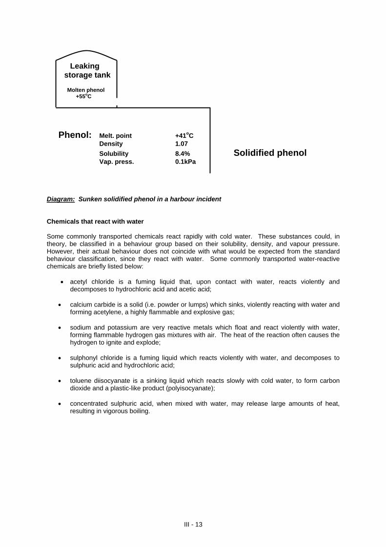
III - 13
Leaking storage tank Molten phenol +55oC
Phenol: Melt. point +41oC Density 1.07
Solubility 8.4% Solidified phenol Vap. press. 0.1kPa Diagram: Sunken solidified phenol in a harbour incident Chemicals that react with water Some commonly transported chemicals react rapidly with cold water. These substances could, in theory, be classified in a behaviour group based on their solubility, density, and vapour pressure. However, their actual behaviour does not coincide with what would be expected from the standard behaviour classification, since they react with water. Some commonly transported water-reactive chemicals are briefly listed below:
acetyl chloride is a fuming liquid that, upon contact with water, reacts violently and decomposes to hydrochloric acid and acetic acid;
calcium carbide is a solid (i.e. powder or lumps) which sinks, violently reacting with water and
forming acetylene, a highly flammable and explosive gas;
sodium and potassium are very reactive metals which float and react violently with water, forming flammable hydrogen gas mixtures with air. The heat of the reaction often causes the hydrogen to ignite and explode;
sulphonyl chloride is a fuming liquid which reacts violently with water, and decomposes to
sulphuric acid and hydrochloric acid;
toluene diisocyanate is a sinking liquid which reacts slowly with cold water, to form carbon dioxide and a plastic-like product (polyisocyanate);
concentrated sulphuric acid, when mixed with water, may release large amounts of heat,
resulting in vigorous boiling.

SECTION IV
PHYSICAL-CHEMICAL PROPERTIES OF SELECTED CHEMICALS
CARRIED IN BULK
Sources: 1) Helcom Combating Manual, Volume III. 2) International Maritime Dangerous Goods Code. 3) GESAMP Composite List, February 1999.
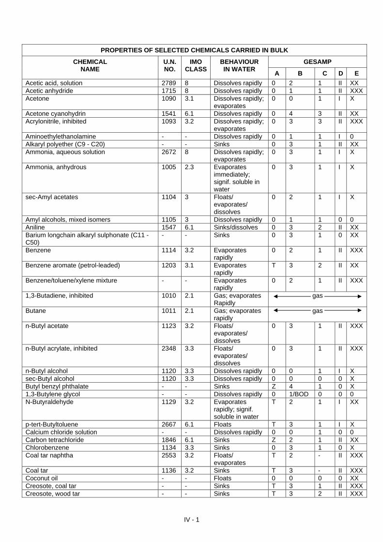
PROPERTIES OF SELECTED CHEMICALS CARRIED IN BULK
GESAMP CHEMICAL NAME
U.N. NO.
IMO CLASS
BEHAVIOUR IN WATER
A B C D E
Acetic acid, solution 2789 8 Dissolves rapidly 0 2 1 II XX Acetic anhydride 1715 8 Dissolves rapidly 0 1 1 II XXX Acetone 1090 3.1 Dissolves rapidly;
evaporates 0 0 1 I X
Acetone cyanohydrin 1541 6.1 Dissolves rapidly 0 4 3 II XX Acrylonitrile, inhibited 1093 3.2 Dissolves rapidly;
evaporates 0 3 3 II XXX
Aminoethylethanolamine - - Dissolves rapidly 0 1 1 I 0 Alkaryl polyether (C9 - C20) - - Sinks 0 3 1 II XX Ammonia, aqueous solution 2672 8 Dissolves rapidly;
evaporates 0 3 1 I X
Ammonia, anhydrous 1005 2.3 Evaporates immediately; signif. soluble in water
0 3 1 I X
sec-Amyl acetates 1104 3 Floats/ evaporates/ dissolves
0 2 1 I X
Amyl alcohols, mixed isomers 1105 3 Dissolves rapidly 0 1 1 0 0 Aniline 1547 6.1 Sinks/dissolves 0 3 2 II XX Barium longchain alkaryl sulphonate (C11 - C50)
- - Sinks 0 3 1 0 XX
Benzene 1114 3.2 Evaporates rapidly
0 2 1 II XXX
Benzene aromate (petrol-leaded) 1203 3.1 Evaporates rapidly
T 3 2 II XX
Benzene/toluene/xylene mixture - - Evaporates rapidly
0 2 1 II XXX
1,3-Butadiene, inhibited 1010 2.1 Gas; evaporates Rapidly
gas
Butane 1011 2.1 Gas; evaporates rapidly
gas
n-Butyl acetate 1123 3.2 Floats/ evaporates/ dissolves
0 3 1 II XXX
n-Butyl acrylate, inhibited 2348 3.3 Floats/ evaporates/ dissolves
0 3 1 II XXX
n-Butyl alcohol 1120 3.3 Dissolves rapidly 0 0 1 I X sec-Butyl alcohol 1120 3.3 Dissolves rapidly 0 0 0 0 X Butyl benzyl phthalate - - Sinks Z 4 1 0 X 1,3-Butylene glycol - - Dissolves rapidly 0 1/BOD 0 0 0 N-Butyraldehyde 1129 3.2 Evaporates
rapidly; signif. soluble in water
T 2 1 I XX
p-tert-Butyltoluene 2667 6.1 Floats T 3 1 I X Calcium chloride solution - - Dissolves rapidly 0 0 1 0 0 Carbon tetrachloride 1846 6.1 Sinks Z 2 1 II XX Chlorobenzene 1134 3.3 Sinks 0 3 1 0 X Coal tar naphtha 2553 3.2 Floats/
evaporates T 2 - II XXX
Coal tar 1136 3.2 Sinks T 3 - II XXX Coconut oil - - Floats 0 0 0 0 XX Creosote, coal tar - - Sinks T 3 1 II XXX Creosote, wood tar - - Sinks T 3 2 II XXX
IV - 1
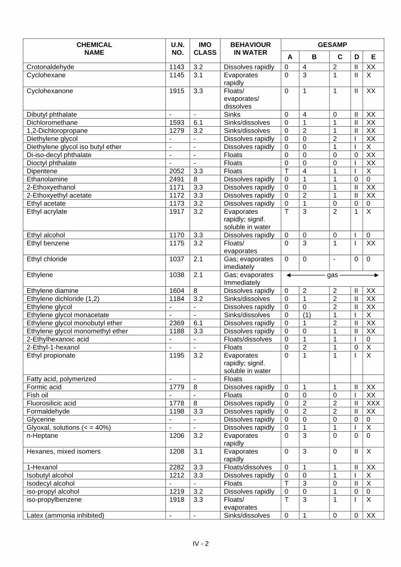
GESAMP CHEMICAL NAME
U.N. NO.
IMO CLASS
BEHAVIOUR IN WATER
A B C D E
Crotonaldehyde 1143 3.2 Dissolves rapidly 0 4 2 II XX Cyclohexane 1145 3.1 Evaporates
rapidly 0 3 1 II X
Cyclohexanone 1915 3.3 Floats/ evaporates/ dissolves
0 1 1 II XX
Dibutyl phthalate - - Sinks 0 4 0 II XX Dichloromethane 1593 6.1 Sinks/dissolves 0 1 1 II XX 1,2-Dichloropropane 1279 3.2 Sinks/dissolves 0 2 1 II XX Diethylene glycol - - Dissolves rapidly 0 0 2 I XX Diethylene glycol iso butyl ether - - Dissolves rapidly 0 0 1 I X Di-iso-decyl phthalate - - Floats 0 0 0 0 XX Dioctyl phthalate - - Floats 0 0 0 I XX Dipentene 2052 3.3 Floats T 4 1 I X Ethanolamine 2491 8 Dissolves rapidly 0 1 1 0 0 2-Ethoxyethanol 1171 3.3 Dissolves rapidly 0 0 1 II XX 2-Ethoxyethyl acetate 1172 3.3 Dissolves rapidly 0 2 1 II XX Ethyl acetate 1173 3.2 Dissolves rapidly 0 1 0 0 0 Ethyl acrylate 1917 3.2 Evaporates
rapidly; signif. soluble in water
T 3 2 1 X
Ethyl alcohol 1170 3.3 Dissolves rapidly 0 0 0 I 0 Ethyl benzene 1175 3.2 Floats/
evaporates 0 3 1 I XX
Ethyl chloride 1037 2.1 Gas; evaporates imediately
0 0 - 0 0
Ethylene 1038 2.1 Gas; evaporates Immediately
gas
Ethylene diamine 1604 8 Dissolves rapidly 0 2 2 II XX Ethylene dichloride (1,2) 1184 3.2 Sinks/dissolves 0 1 2 II XX Ethylene glycol - - Dissolves rapidly 0 0 2 II XX Ethylene glycol monacetate - - Sinks/dissolves 0 (1) 1 I X Ethylene glycol monobutyl ether 2369 6.1 Dissolves rapidly 0 1 2 II XX Ethylene glycol monomethyl ether 1188 3.3 Dissolves rapidly 0 0 1 II XX 2-Ethylhexanoic acid - - Floats/dissolves 0 1 1 I 0 2-Ethyl-1-hexanol - - Floats 0 2 1 0 X Ethyl propionate 1195 3.2 Evaporates
rapidly; signif. soluble in water
0 1 1 I X
Fatty acid, polymerized - - Floats Formic acid 1779 8 Dissolves rapidly 0 1 1 II XX Fish oil - - Floats 0 0 0 I XX Fluorosilicic acid 1778 8 Dissolves rapidly 0 2 2 II XXX Formaldehyde 1198 3.3 Dissolves rapidly 0 2 2 II XX Glycerine - - Dissolves rapidly 0 0 0 0 0 Glyoxal, solutions (< = 40%) - - Dissolves rapidly 0 1 1 I X n-Heptane 1206 3.2 Evaporates
rapidly 0 3 0 0 0
Hexanes, mixed isomers 1208 3.1 Evaporates rapidly
0 3 0 II X
1-Hexanol 2282 3.3 Floats/dissolves 0 1 1 II XX Isobutyl alcohol 1212 3.3 Dissolves rapidly 0 0 1 I X Isodecyl alcohol - - Floats T 3 0 II X iso-propyl alcohol 1219 3.2 Dissolves rapidly 0 0 1 0 0 iso-propylbenzene 1918 3.3 Floats/
evaporates T 3 1 I X
Latex (ammonia inhibited) - - Sinks/dissolves 0 1 0 0 XX
IV - 2
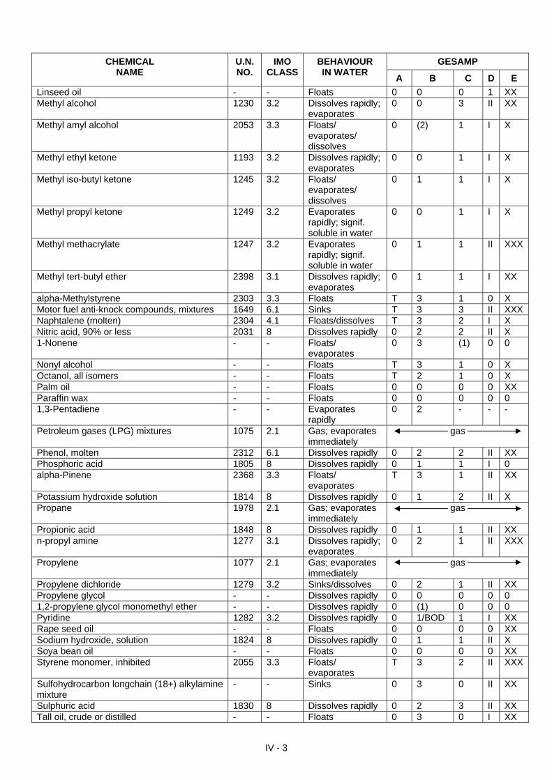
GESAMP CHEMICAL NAME
U.N. NO.
IMO CLASS
BEHAVIOUR IN WATER
A B C D E
Linseed oil - - Floats 0 0 0 1 XX Methyl alcohol 1230 3.2 Dissolves rapidly;
evaporates 0 0 3 II XX
Methyl amyl alcohol 2053 3.3 Floats/ evaporates/ dissolves
0 (2) 1 I X
Methyl ethyl ketone 1193 3.2 Dissolves rapidly; evaporates
0 0 1 I X
Methyl iso-butyl ketone 1245 3.2 Floats/ evaporates/ dissolves
0 1 1 I X
Methyl propyl ketone 1249 3.2 Evaporates rapidly; signif. soluble in water
0 0 1 I X
Methyl methacrylate 1247 3.2 Evaporates rapidly; signif. soluble in water
0 1 1 II XXX
Methyl tert-butyl ether 2398 3.1 Dissolves rapidly; evaporates
0 1 1 I XX
alpha-Methylstyrene 2303 3.3 Floats T 3 1 0 X Motor fuel anti-knock compounds, mixtures 1649 6.1 Sinks T 3 3 II XXX Naphtalene (molten) 2304 4.1 Floats/dissolves T 3 2 I X Nitric acid, 90% or less 2031 8 Dissolves rapidly 0 2 2 II X 1-Nonene - - Floats/
evaporates 0 3 (1) 0 0
Nonyl alcohol - - Floats T 3 1 0 X Octanol, all isomers - - Floats T 2 1 0 X Palm oil - - Floats 0 0 0 0 XX Paraffin wax - - Floats 0 0 0 0 0 1,3-Pentadiene - - Evaporates
rapidly 0 2 - - -
Petroleum gases (LPG) mixtures 1075 2.1 Gas; evaporates immediately
gas
Phenol, molten 2312 6.1 Dissolves rapidly 0 2 2 II XX Phosphoric acid 1805 8 Dissolves rapidly 0 1 1 I 0 alpha-Pinene 2368 3.3 Floats/
evaporates T 3 1 II XX
Potassium hydroxide solution 1814 8 Dissolves rapidly 0 1 2 II X Propane 1978 2.1 Gas; evaporates
immediately gas
Propionic acid 1848 8 Dissolves rapidly 0 1 1 II XX n-propyl amine 1277 3.1 Dissolves rapidly;
evaporates 0 2 1 II XXX
Propylene 1077 2.1 Gas; evaporates immediately
gas
Propylene dichloride 1279 3.2 Sinks/dissolves 0 2 1 II XX Propylene glycol - - Dissolves rapidly 0 0 0 0 0 1,2-propylene glycol monomethyl ether - - Dissolves rapidly 0 (1) 0 0 0 Pyridine 1282 3.2 Dissolves rapidly 0 1/BOD 1 I XX Rape seed oil - - Floats 0 0 0 0 XX Sodium hydroxide, solution 1824 8 Dissolves rapidly 0 1 1 II X Soya bean oil - - Floats 0 0 0 0 XX Styrene monomer, inhibited 2055 3.3 Floats/
evaporates T 3 2 II XXX
Sulfohydrocarbon longchain (18+) alkylamine mixture
- - Sinks 0 3 0 II XX
Sulphuric acid 1830 8 Dissolves rapidly 0 2 3 II XX Tall oil, crude or distilled - - Floats 0 3 0 I XX
IV - 3
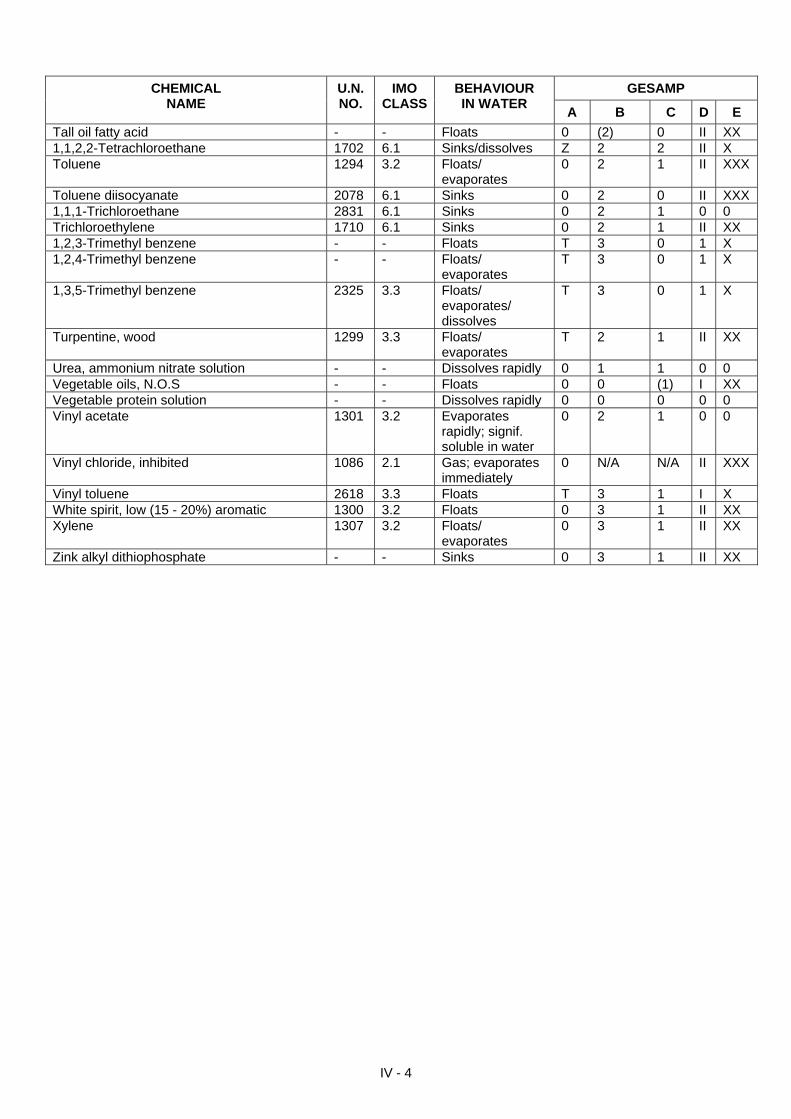
IV - 4
GESAMP CHEMICAL NAME
U.N. NO.
IMO CLASS
BEHAVIOUR IN WATER
A B C D E
Tall oil fatty acid - - Floats 0 (2) 0 II XX 1,1,2,2-Tetrachloroethane 1702 6.1 Sinks/dissolves Z 2 2 II X Toluene 1294 3.2 Floats/
evaporates 0 2 1 II XXX
Toluene diisocyanate 2078 6.1 Sinks 0 2 0 II XXX 1,1,1-Trichloroethane 2831 6.1 Sinks 0 2 1 0 0 Trichloroethylene 1710 6.1 Sinks 0 2 1 II XX 1,2,3-Trimethyl benzene - - Floats T 3 0 1 X 1,2,4-Trimethyl benzene - - Floats/
evaporates T 3 0 1 X
1,3,5-Trimethyl benzene 2325 3.3 Floats/ evaporates/ dissolves
T 3 0 1 X
Turpentine, wood 1299 3.3 Floats/ evaporates
T 2 1 II XX
Urea, ammonium nitrate solution - - Dissolves rapidly 0 1 1 0 0 Vegetable oils, N.O.S - - Floats 0 0 (1) I XX Vegetable protein solution - - Dissolves rapidly 0 0 0 0 0 Vinyl acetate 1301 3.2 Evaporates
rapidly; signif. soluble in water
0 2 1 0 0
Vinyl chloride, inhibited 1086 2.1 Gas; evaporates immediately
0 N/A N/A II XXX
Vinyl toluene 2618 3.3 Floats T 3 1 I X White spirit, low (15 - 20%) aromatic 1300 3.2 Floats 0 3 1 II XX Xylene 1307 3.2 Floats/
evaporates 0 3 1 II XX
Zink alkyl dithiophosphate - - Sinks 0 3 1 II XX
SECTION V
CHEMICAL COMPATIBILITY MATRIX
The aim of such a matrix is to provide the user with a screening tool for potential incompatibilities
of chemical substances in close proximity Sources: 1) CHRIS, Hazardous Chemical Data, United States Department of Transportation, United
States Coast Guard. 2) Proceedings of the Marine Safety Council, Volume 55, 56, 1998.
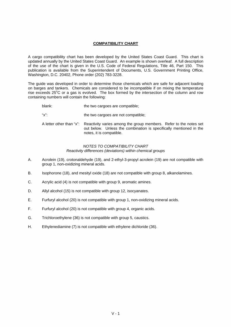
COMPATIBILITY CHART A cargo compatibility chart has been developed by the United States Coast Guard. This chart is updated annually by the United States Coast Guard. An example is shown overleaf. A full description of the use of the chart is given in the U.S. Code of Federal Regulations, Title 46, Part 150. This publication is available from the Superintendent of Documents, U.S. Government Printing Office, Washington, D.C. 20402, Phone order (202) 783-3228. The guide was developed in order to determine those chemicals which are safe for adjacent loading on barges and tankers. Chemicals are considered to be incompatible if on mixing the temperature rise exceeds 25oC or a gas is evolved. The box formed by the intersection of the column and row containing numbers will contain the following: blank: the two cargoes are compatible; “x”: the two cargoes are not compatible; A letter other than “x”: Reactivity varies among the group members. Refer to the notes set
out below. Unless the combination is specifically mentioned in the notes, it is compatible.
NOTES TO COMPATIBILITY CHART Reactivity differences (deviations) within chemical groups
A. Acrolein (19), crotonaldehyde (19), and 2-ethyl-3-propyl acrolein (19) are not compatible with
group 1, non-oxidizing mineral acids. B. Isophorone (18), and mesityl oxide (18) are not compatible with group 8, alkanolamines. C. Acrylic acid (4) is not compatible with group 9, aromatic amines. D. Allyl alcohol (15) is not compatible with group 12, isocyanates. E. Furfuryl alcohol (20) is not compatible with group 1, non-oxidizing mineral acids. F. Furfuryl alcohol (20) is not compatible with group 4, organic acids. G. Trichloroethylene (36) is not compatible with group 5, caustics. H. Ethylenediamine (7) is not compatible with ethylene dichloride (36).
V - 1
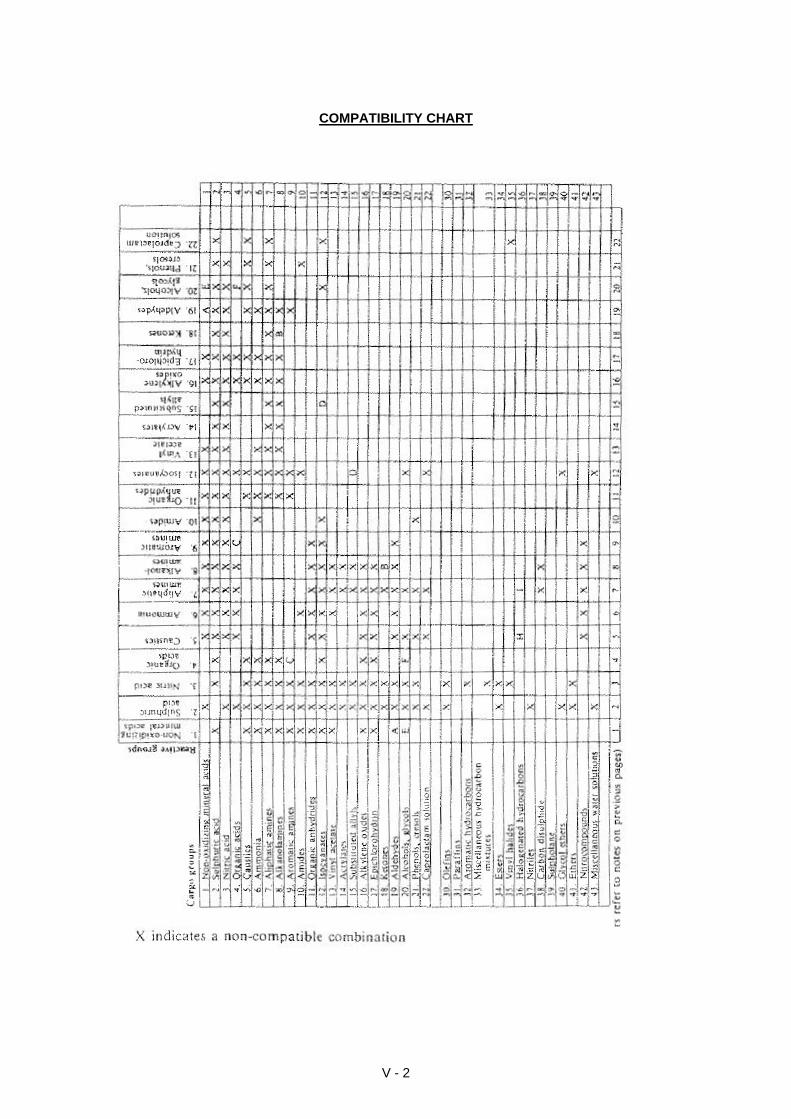
COMPATIBILITY CHART
V - 2
SECTION VI
MATERIALS RESISTANCE TABLE
The chemicals appearing in the materials resistance table refer to pure chemical products. The effect of the chemical mixtures or impurities in chemical products on material resistance
can be noticeably stronger compared with the pure product. The resistance of a material is also greatly affected by temperature and concentration of the chemical with which it is in contact. Exceptions can occur for substances belonging to the same chemical
group. For this reason, the information contained in the table should be taken only as indicative. If possible, the durability of a material should be checked against
the chemical substance and the manufacturer of the equipment should be consulted.
The requirement for system earthing must be checked for hoses, basins and tanks without electrical leads which are manufactured from plastic or rubber materials.
Account should also be taken of the mechanical resistance of the material. For example, a tank manufactured from plastic is not a pressure vessel, nor can it withstand the evaporation pressure of liquid gases enclosed within it.
Source: 1) Tokeva Instructions, Finnish Emergency Services College and Nordic Council of Ministers.
The letters at the top of the table columns relate to the following chemicals and chemical groups (an example is given in brackets): A chlorine K chlorinated hydrocarbon (carbon tetrachloride) B sulphur dioxide L alcohols (isopropanol) C ammonia M ketones (asetone) D oxidized substances (hydrogen peroxide) N ethers (diethylether) E salt solutions (natrium chloride solution) O esters (ethylacetate) F alkalis, lyes (natrium hydroxide) P nitriles (acrylnitrile) G inorganic acids (sulphuric acid) Q amines (triethanolamine) H organic acids (formic acid) R amides (dimethylformamide) I aliphatic hydrocarbons (fuel oil) S aldehydes (formaldehyde) J aromatic hydrocarbons (toluene)
VI - 1
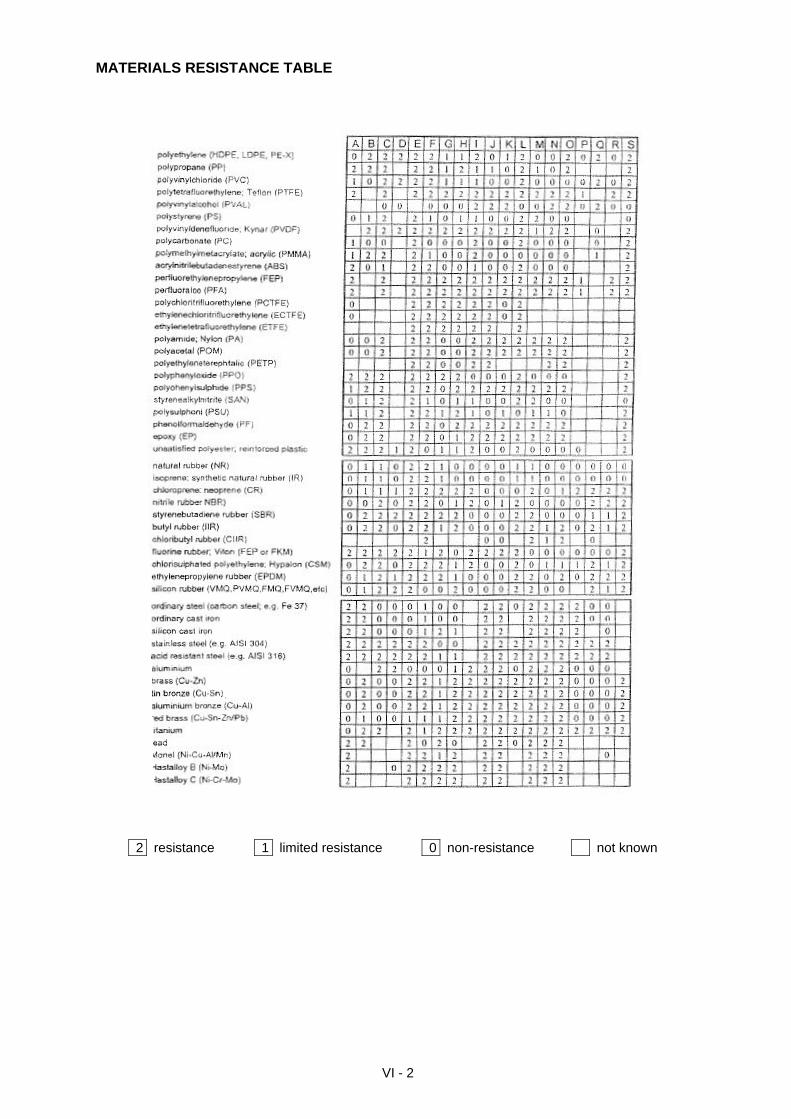
MATERIALS RESISTANCE TABLE
VI - 2
2 resistance 1 limited resistance 0 non-resistance not known
SECTION VII
HAZARDOUS SUBSTANCE INFORMATION SHEET
The collection of relevant and specific information regarding the properties of a chemical is essential. Having a “fill in blank” information sheet ensures that relevant information is not missed and such a data sheet forms a record for the collection of
data which can be quickly passed to others in various stages of the response Source: 1) United States Coast Guard National Strike Force Field Guide Book.
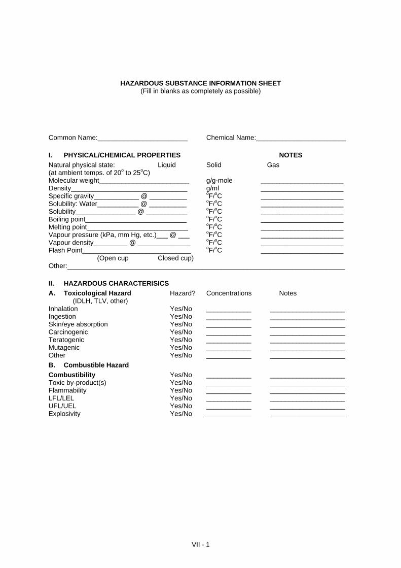
HAZARDOUS SUBSTANCE INFORMATION SHEET (Fill in blanks as completely as possible)
Common Name:________________________ Chemical Name:________________________
I. PHYSICAL/CHEMICAL PROPERTIES NOTES
Natural physical state: Liquid Solid Gas (at ambient temps. of 20o to 25oC) Molecular weight________________________ g/g-mole ______________________ Density_______________________________ g/ml ______________________ Specific gravity____________ @ __________ oF/oC ______________________ Solubility: Water___________ @ __________ oF/oC ______________________ Solubility________________ @ ___________ oF/oC ______________________ Boiling point___________________________ oF/oC ______________________ Melting point___________________________ oF/oC ______________________ Vapour pressure (kPa, mm Hg, etc.)___ @ ___ oF/oC ______________________ Vapour density_________ @ ______________ oF/oC ______________________ Flash Point_____________________________ oF/oC ______________________ (Open cup Closed cup) Other:__________________________________________________________________________
II. HAZARDOUS CHARACTERISICS
A. Toxicological Hazard Hazard? Concentrations Notes (IDLH, TLV, other) Inhalation Yes/No ____________ ____________________ Ingestion Yes/No ____________ ____________________ Skin/eye absorption Yes/No ____________ ____________________ Carcinogenic Yes/No ____________ ____________________ Teratogenic Yes/No ____________ ____________________ Mutagenic Yes/No ____________ ____________________ Other Yes/No ____________ ____________________
B. Combustible Hazard
Combustibility Yes/No ____________ ____________________ Toxic by-product(s) Yes/No ____________ ____________________ Flammability Yes/No ____________ ____________________ LFL/LEL Yes/No ____________ ____________________ UFL/UEL Yes/No ____________ ____________________ Explosivity Yes/No ____________ ____________________
VII - 1
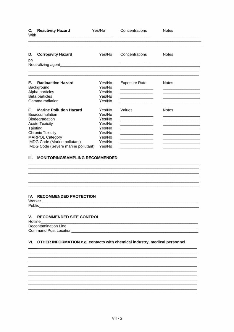
C. Reactivity Hazard Yes/No Concentrations Notes With___________________________________ ______________ _________________ _______________________________________________________________________________ _______________________________________________________________________________
D. Corrosivity Hazard Yes/No Concentrations Notes
ph __________________ ______________ _________________ Neutralizing agent________________________________________________________________ ______________________________________________________________________________ ______________________________________________________________________________ E. Radioactive Hazard Yes/No Exposure Rate Notes Background Yes/No _______________ _________________ Alpha particles Yes/No _______________ _________________ Beta particles Yes/No _______________ _________________ Gamma radiation Yes/No _______________ _________________ F. Marine Pollution Hazard Yes/No Values Notes Bioaccumulation Yes/No _______________ _________________ Biodegradation Yes/No _______________ _________________ Acute Toxicity Yes/No _______________ _________________ Tainting Yes/No _______________ _________________ Chronic Toxicity Yes/No _______________ _________________ MARPOL Category Yes/No _______________ _________________ IMDG Code (Marine pollutant) Yes/No _______________ _________________ IMDG Code (Severe marine pollutant) Yes/No _______________ _________________
III. MONITORING/SAMPLING RECOMMENDED ______________________________________________________________________________ ______________________________________________________________________________ ______________________________________________________________________________ ______________________________________________________________________________ ______________________________________________________________________________ ______________________________________________________________________________
IV. RECOMMENDED PROTECTION Worker________________________________________________________________________ Public_________________________________________________________________________
V. RECOMMENDED SITE CONTROL Hotline________________________________________________________________________ Decontamination Line____________________________________________________________ Command Post Location__________________________________________________________
VI. OTHER INFORMATION e.g. contacts with chemical industry, medical personnel _____________________________________________________________________________ _____________________________________________________________________________ _____________________________________________________________________________ _____________________________________________________________________________ _____________________________________________________________________________ _____________________________________________________________________________ _____________________________________________________________________________ _____________________________________________________________________________ _____________________________________________________________________________ _____________________________________________________________________________ _____________________________________________________________________________
VII - 2
VII - 3
Hazard Assessment Decision Tree: the oval boxes along each path represent decision points that are based upon physical properties, and the triangles are decision points set by environmental conditions. The rectangular boxes identify physical phenomena (boiling, dispersion, etc.) which can occur. Each path leads to one or more circles, which are points at which an evaluation can be made of the danger before considering what response action is appropriate.
SECTION VIII
HAZARDOUS CHEMICAL EMERGENCY RESPONSE
CHECKLIST
A checklist on the items that need to be considered to ensure safety of response personnel
Source: 1) United States Coast Guard National Strike Force Field Guide Book.
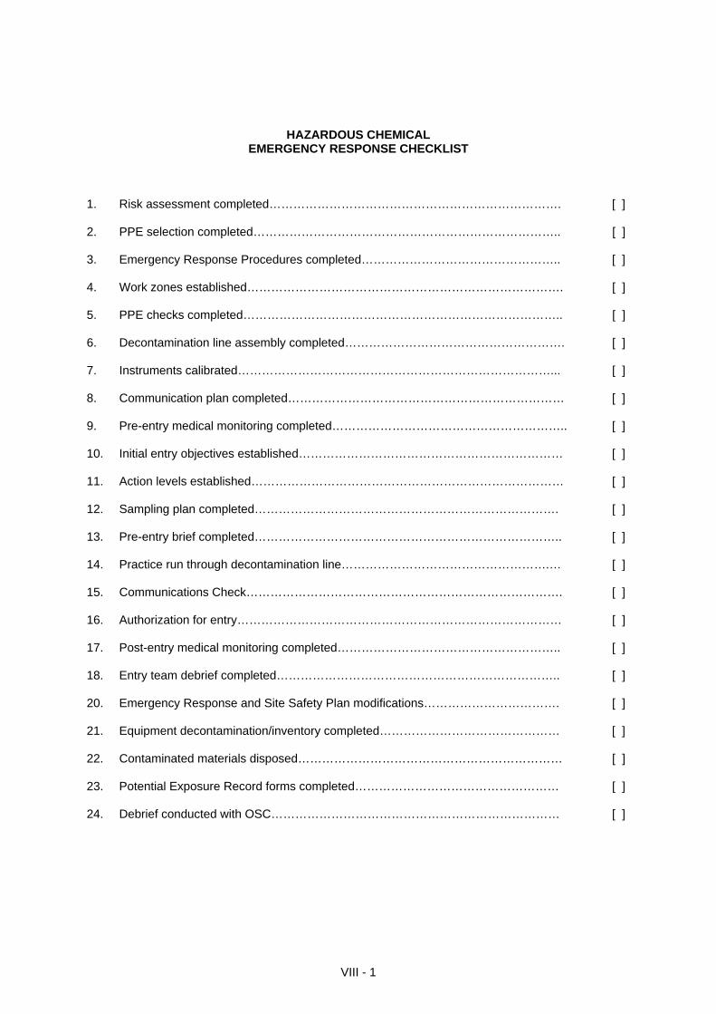
HAZARDOUS CHEMICAL
EMERGENCY RESPONSE CHECKLIST 1. Risk assessment completed………………………………………………………………. [ ] 2. PPE selection completed………………………………………………………………….. [ ] 3. Emergency Response Procedures completed………………………………………….. [ ] 4. Work zones established……………………………………………………………………. [ ] 5. PPE checks completed…………………………………………………………………….. [ ] 6. Decontamination line assembly completed………………………………………………. [ ] 7. Instruments calibrated……………………………………………………………………... [ ] 8. Communication plan completed…………………………………………………………… [ ] 9. Pre-entry medical monitoring completed………………………………………………….. [ ] 10. Initial entry objectives established………………………………………………………… [ ] 11. Action levels established…………………………………………………………………… [ ] 12. Sampling plan completed…………………………………………………………………. [ ] 13. Pre-entry brief completed………………………………………………………………….. [ ] 14. Practice run through decontamination line…………………………………………….… [ ] 15. Communications Check……………………………………………………………………. [ ] 16. Authorization for entry……………………………………………………………………… [ ] 17. Post-entry medical monitoring completed……………………………………………….. [ ] 18. Entry team debrief completed…………………………………………………………….. [ ] 20. Emergency Response and Site Safety Plan modifications……………………………. [ ] 21. Equipment decontamination/inventory completed……………………………………… [ ] 22. Contaminated materials disposed………………………………………………………… [ ] 23. Potential Exposure Record forms completed…………………………………………… [ ] 24. Debrief conducted with OSC……………………………………………………………… [ ]
VIII - 1
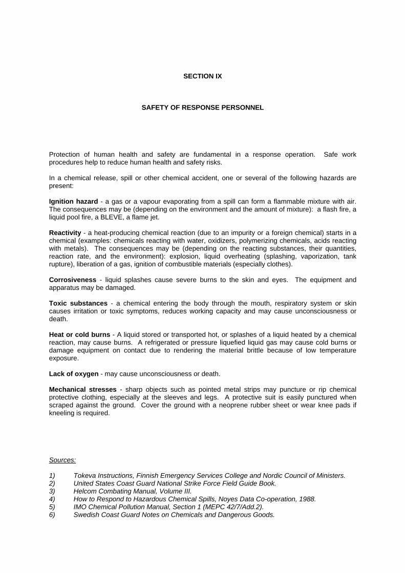
SECTION IX
SAFETY OF RESPONSE PERSONNEL
Protection of human health and safety are fundamental in a response operation. Safe work procedures help to reduce human health and safety risks. In a chemical release, spill or other chemical accident, one or several of the following hazards are present: Ignition hazard - a gas or a vapour evaporating from a spill can form a flammable mixture with air. The consequences may be (depending on the environment and the amount of mixture): a flash fire, a liquid pool fire, a BLEVE, a flame jet. Reactivity - a heat-producing chemical reaction (due to an impurity or a foreign chemical) starts in a chemical (examples: chemicals reacting with water, oxidizers, polymerizing chemicals, acids reacting with metals). The consequences may be (depending on the reacting substances, their quantities, reaction rate, and the environment): explosion, liquid overheating (splashing, vaporization, tank rupture), liberation of a gas, ignition of combustible materials (especially clothes). Corrosiveness - liquid splashes cause severe burns to the skin and eyes. The equipment and apparatus may be damaged. Toxic substances - a chemical entering the body through the mouth, respiratory system or skin causes irritation or toxic symptoms, reduces working capacity and may cause unconsciousness or death. Heat or cold burns - A liquid stored or transported hot, or splashes of a liquid heated by a chemical reaction, may cause burns. A refrigerated or pressure liquefied liquid gas may cause cold burns or damage equipment on contact due to rendering the material brittle because of low temperature exposure. Lack of oxygen - may cause unconsciousness or death. Mechanical stresses - sharp objects such as pointed metal strips may puncture or rip chemical protective clothing, especially at the sleeves and legs. A protective suit is easily punctured when scraped against the ground. Cover the ground with a neoprene rubber sheet or wear knee pads if kneeling is required. Sources: 1) Tokeva Instructions, Finnish Emergency Services College and Nordic Council of Ministers. 2) United States Coast Guard National Strike Force Field Guide Book. 3) Helcom Combating Manual, Volume III. 4) How to Respond to Hazardous Chemical Spills, Noyes Data Co-operation, 1988. 5) IMO Chemical Pollution Manual, Section 1 (MEPC 42/7/Add.2). 6) Swedish Coast Guard Notes on Chemicals and Dangerous Goods.
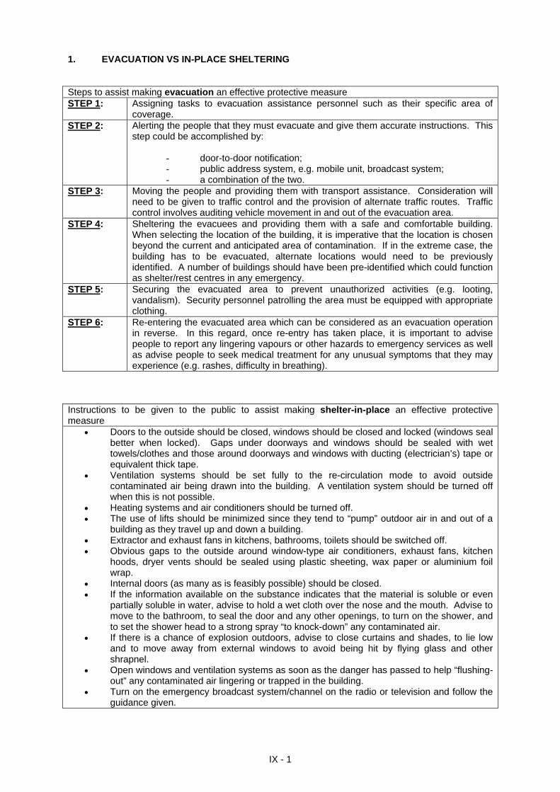
1. EVACUATION VS IN-PLACE SHELTERING Steps to assist making evacuation an effective protective measure STEP 1: Assigning tasks to evacuation assistance personnel such as their specific area of
coverage. STEP 2: Alerting the people that they must evacuate and give them accurate instructions. This
step could be accomplished by:
- door-to-door notification; - public address system, e.g. mobile unit, broadcast system; - a combination of the two.
STEP 3: Moving the people and providing them with transport assistance. Consideration will need to be given to traffic control and the provision of alternate traffic routes. Traffic control involves auditing vehicle movement in and out of the evacuation area.
STEP 4: Sheltering the evacuees and providing them with a safe and comfortable building. When selecting the location of the building, it is imperative that the location is chosen beyond the current and anticipated area of contamination. If in the extreme case, the building has to be evacuated, alternate locations would need to be previously identified. A number of buildings should have been pre-identified which could function as shelter/rest centres in any emergency.
STEP 5: Securing the evacuated area to prevent unauthorized activities (e.g. looting, vandalism). Security personnel patrolling the area must be equipped with appropriate clothing.
STEP 6: Re-entering the evacuated area which can be considered as an evacuation operation in reverse. In this regard, once re-entry has taken place, it is important to advise people to report any lingering vapours or other hazards to emergency services as well as advise people to seek medical treatment for any unusual symptoms that they may experience (e.g. rashes, difficulty in breathing).
Instructions to be given to the public to assist making shelter-in-place an effective protective measure
Doors to the outside should be closed, windows should be closed and locked (windows seal better when locked). Gaps under doorways and windows should be sealed with wet towels/clothes and those around doorways and windows with ducting (electrician’s) tape or equivalent thick tape.
Ventilation systems should be set fully to the re-circulation mode to avoid outside contaminated air being drawn into the building. A ventilation system should be turned off when this is not possible.
Heating systems and air conditioners should be turned off. The use of lifts should be minimized since they tend to “pump” outdoor air in and out of a
building as they travel up and down a building. Extractor and exhaust fans in kitchens, bathrooms, toilets should be switched off. Obvious gaps to the outside around window-type air conditioners, exhaust fans, kitchen
hoods, dryer vents should be sealed using plastic sheeting, wax paper or aluminium foil wrap.
Internal doors (as many as is feasibly possible) should be closed. If the information available on the substance indicates that the material is soluble or even
partially soluble in water, advise to hold a wet cloth over the nose and the mouth. Advise to move to the bathroom, to seal the door and any other openings, to turn on the shower, and to set the shower head to a strong spray “to knock-down” any contaminated air.
If there is a chance of explosion outdoors, advise to close curtains and shades, to lie low and to move away from external windows to avoid being hit by flying glass and other shrapnel.
Open windows and ventilation systems as soon as the danger has passed to help “flushing-out” any contaminated air lingering or trapped in the building.
Turn on the emergency broadcast system/channel on the radio or television and follow the guidance given.
IX - 1
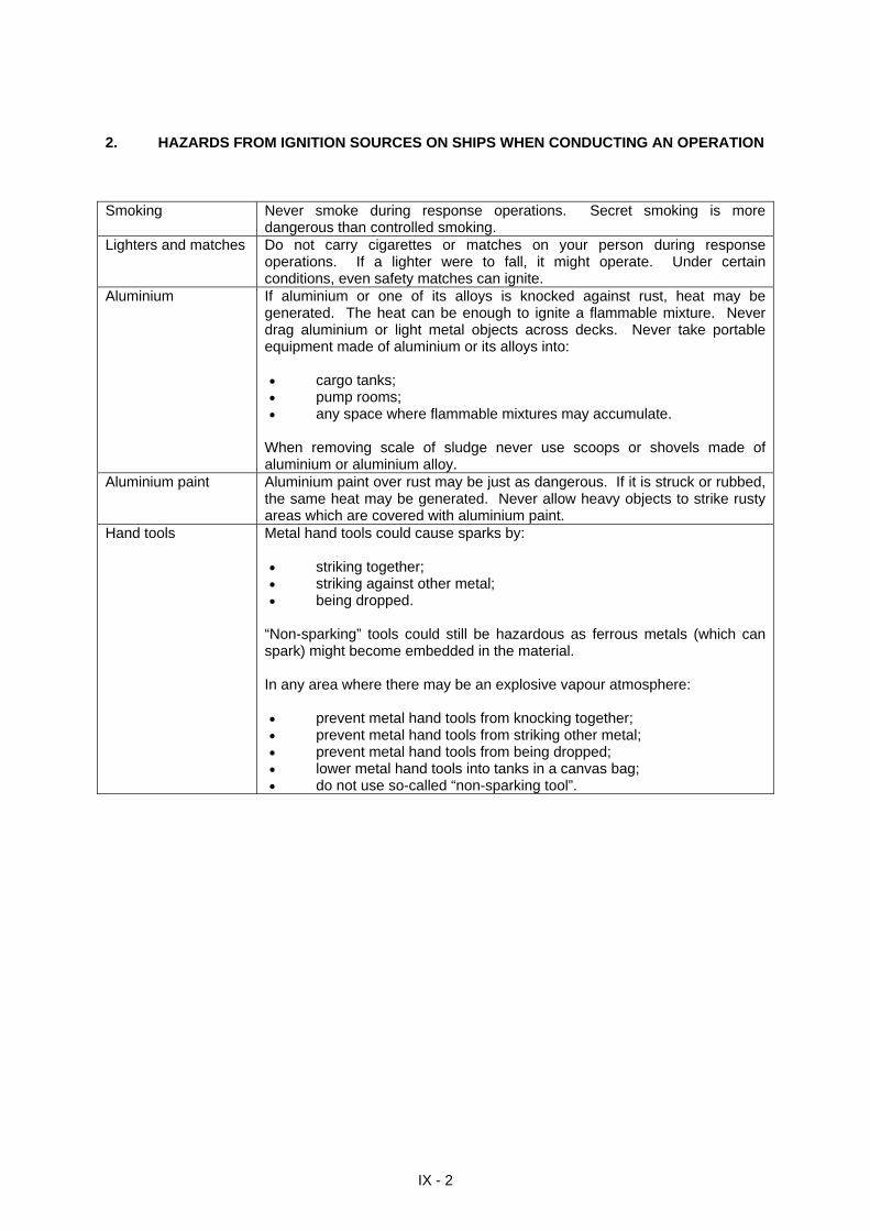
2. HAZARDS FROM IGNITION SOURCES ON SHIPS WHEN CONDUCTING AN OPERATION Smoking Never smoke during response operations. Secret smoking is more
dangerous than controlled smoking. Lighters and matches Do not carry cigarettes or matches on your person during response
operations. If a lighter were to fall, it might operate. Under certain conditions, even safety matches can ignite.
Aluminium If aluminium or one of its alloys is knocked against rust, heat may be generated. The heat can be enough to ignite a flammable mixture. Never drag aluminium or light metal objects across decks. Never take portable equipment made of aluminium or its alloys into: cargo tanks; pump rooms; any space where flammable mixtures may accumulate.
When removing scale of sludge never use scoops or shovels made of aluminium or aluminium alloy.
Aluminium paint Aluminium paint over rust may be just as dangerous. If it is struck or rubbed, the same heat may be generated. Never allow heavy objects to strike rusty areas which are covered with aluminium paint.
Hand tools Metal hand tools could cause sparks by: striking together; striking against other metal; being dropped.
“Non-sparking” tools could still be hazardous as ferrous metals (which can spark) might become embedded in the material. In any area where there may be an explosive vapour atmosphere: prevent metal hand tools from knocking together; prevent metal hand tools from striking other metal; prevent metal hand tools from being dropped; lower metal hand tools into tanks in a canvas bag; do not use so-called “non-sparking tool”.
IX - 2
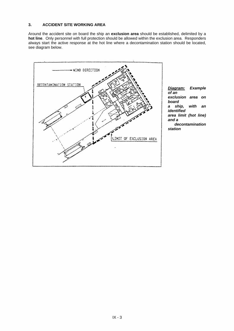
3. ACCIDENT SITE WORKING AREA Around the accident site on board the ship an exclusion area should be established, delimited by a hot line. Only personnel with full protection should be allowed within the exclusion area. Responders always start the active response at the hot line where a decontamination station should be located, see diagram below.
Diagram: Example of an exclusion area on board a ship, with an identified area limit (hot line) and a
decontamination station
IX - 3
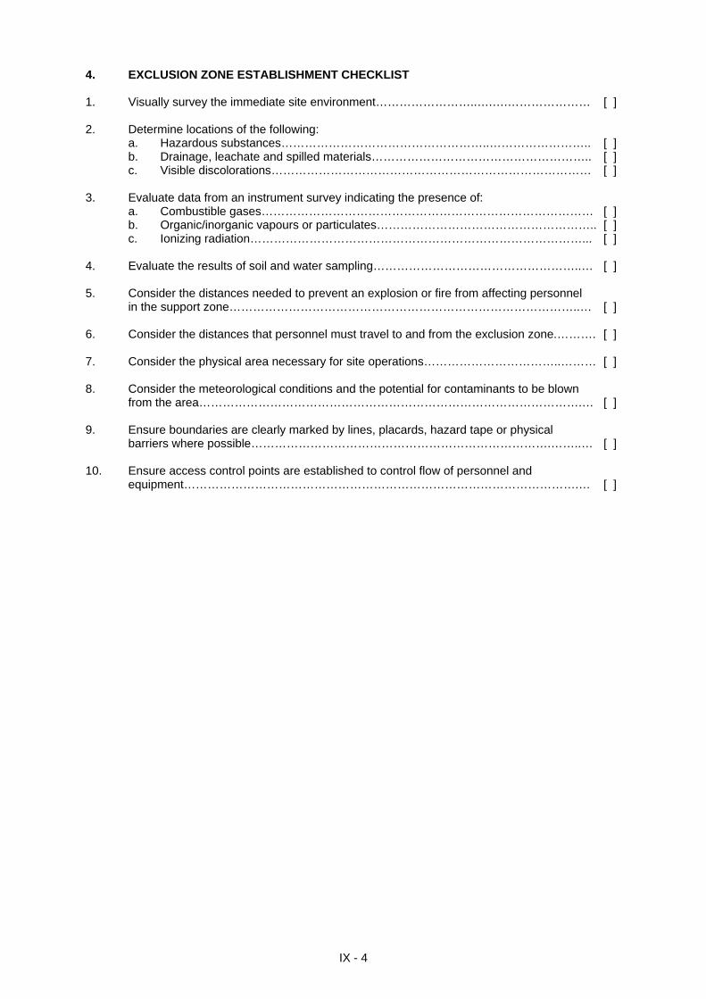
4. EXCLUSION ZONE ESTABLISHMENT CHECKLIST 1. Visually survey the immediate site environment……………………..….….………………… [ ] 2. Determine locations of the following:
a. Hazardous substances……………………………………………..…………………….. [ ] b. Drainage, leachate and spilled materials……………………………………………….. [ ] c. Visible discolorations……………………………………………………………………… [ ]
3. Evaluate data from an instrument survey indicating the presence of: a. Combustible gases………………………………………………………………………… [ ] b. Organic/inorganic vapours or particulates……………………………………………….. [ ] c. Ionizing radiation…………………………………………………………………………... [ ] 4. Evaluate the results of soil and water sampling……………………………………………..… [ ] 5. Consider the distances needed to prevent an explosion or fire from affecting personnel in the support zone……………………………………………………………………………..… [ ] 6. Consider the distances that personnel must travel to and from the exclusion zone.………. [ ] 7. Consider the physical area necessary for site operations……………………………..……… [ ] 8. Consider the meteorological conditions and the potential for contaminants to be blown
from the area…………………………………………………………………………………….… [ ] 9. Ensure boundaries are clearly marked by lines, placards, hazard tape or physical
barriers where possible………………………………………………………………….……..… [ ] 10. Ensure access control points are established to control flow of personnel and equipment……………………………………………………………………………………….… [ ]
IX - 4
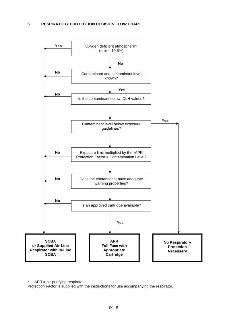
5. RESPIRATORY PROTECTION DECISION FLOW CHART Yes
No No
Yes No
Yes
No
No
No
Yes
Oxygen deficient atmosphere? (< or = 19.5%)
Contaminant and contaminant level known?
Is the contaminant below IDLH values?
Contaminant level below exposure guidelines?
Exposure limit multiplied by the *APR Protection Factor > Contamination Level?
Does the contaminant have adequate warning properties?
Is an approved cartridge available?
SCBA
or Supplied Air-Line Respirator with in-Line
SCBA
APR
Full Face with Appropriate
Cartridge
No Respiratory Protection Necessary
* APR = air-purifying respirator. Protection Factor is supplied with the instructions for use accompanying the respirator.
IX - 5
6. ATMOSPHERIC MONITORING The purpose of monitoring surveys made during site entry is to enable one make a preliminary evaluation of atmospheric hazards. The table below provides guidelines on the action to be taken under different atmospheric hazards.
Hazard Ambient Level Action Explosive atmosphere < 10% LEL
10% - 20% > 20% LEL
Continue investigation. Continue on-site monitoring with extreme caution as higher levels are encountered. Explosion hazards; withdraw from area immediately.
Oxygen < 19.5% 19.5% - 22% > 22.0%
Monitor wearing SCBA. NOTE: Combustible gas readings are not valid in atmospheres with < 19.5% oxygen. Continue investigation with caution. SCBA not needed, based on oxygen content alone. Discontinue inspection; fire hazard potential. Consult specialist.
Radiation < 25 µSv/h - 30 µSv/h > 100 µSv/h
Continue investigation. If radiation is detected above background levels, this signifies the presence of possible radiation sources; at this level, more thorough monitoring is advisable. Consult with a health physicist. Potential radiation hazard; evacuate site. Continue monitoring only upon the advice of a health physicist or medical personnel.
Organic and inorganic vapours/gases
Depends on species Consult standard reference manuals for air concentrations/toxicity data.
Organic vapours/gases Depends on species Consult standard reference manuals for air concentrations/toxicity data.
Organic vapours/gases Depends on species Consult standard reference manuals for air concentrations/toxicity data.
7. PRECAUTIONS WHEN ENTERING ENCLOSED SPACES ON SHIPS Enclosed spaces on ships, e.g.: - cargo pump or
compressor rooms; - ballast tanks; - double bottom tanks;
- empty compartments next to the cargo tanks.
May have contained flammable and/or toxic gases/ vapours.
May be adjacent to spaces containing dangerous cargoes which may have leaked into them.
May contain insufficient oxygen. May be inerted.
Before entering an enclosed space
Obtain permission. Check the atmosphere. Make sure there is someone outside to keep watch. Ensure ventilation equipment works. Have a lifeline, harness and breathing apparatus ready
for use at the entrance. Watching over someone who is in difficulty
DO NOT BECOME THE NEXT CASUALTY YOURSELF. Think. Do not go immediately to the assistance of the person in
trouble. Raise the alarm. Wait for help. Do not enter the space unless you have another person
available to take your place at the entrance. Wear breathing apparatus for entry.
IX - 6
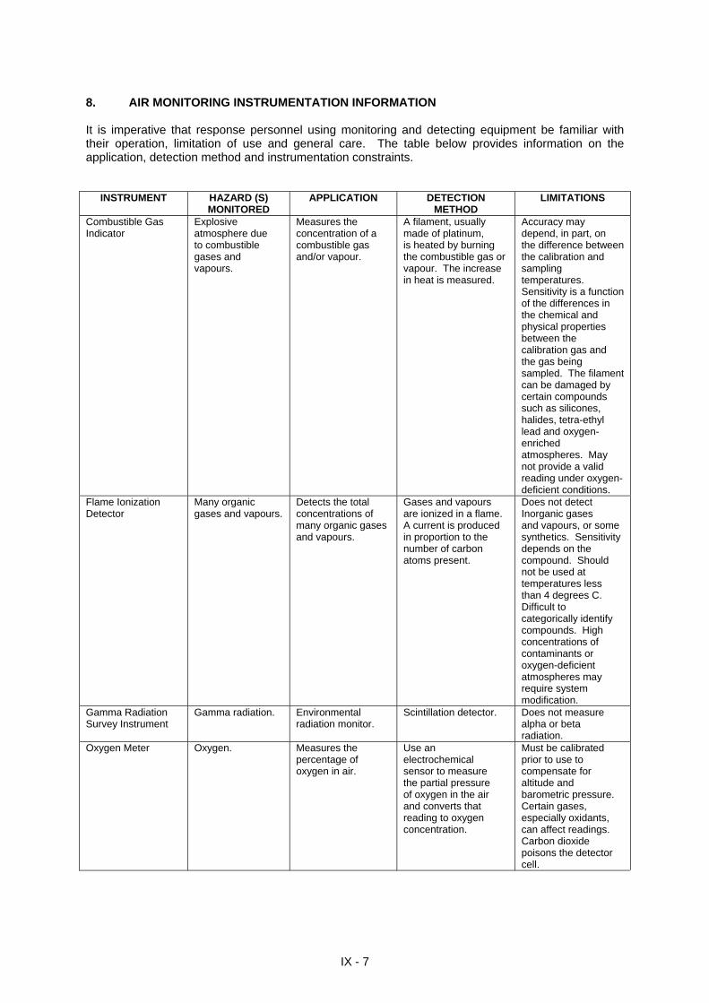
8. AIR MONITORING INSTRUMENTATION INFORMATION It is imperative that response personnel using monitoring and detecting equipment be familiar with their operation, limitation of use and general care. The table below provides information on the application, detection method and instrumentation constraints.
INSTRUMENT HAZARD (S) MONITORED
APPLICATION DETECTION METHOD
LIMITATIONS
Combustible Gas Indicator
Explosive atmosphere due to combustible gases and vapours.
Measures the concentration of a combustible gas and/or vapour.
A filament, usually made of platinum, is heated by burning the combustible gas or vapour. The increase in heat is measured.
Accuracy may depend, in part, on the difference between the calibration and sampling temperatures. Sensitivity is a function of the differences in the chemical and physical properties between the calibration gas and the gas being sampled. The filament can be damaged by certain compounds such as silicones, halides, tetra-ethyl lead and oxygen- enriched atmospheres. May not provide a valid reading under oxygen-deficient conditions.
Flame Ionization Detector
Many organic gases and vapours.
Detects the total concentrations of many organic gases and vapours.
Gases and vapours are ionized in a flame. A current is produced in proportion to the number of carbon atoms present.
Does not detect Inorganic gases and vapours, or some synthetics. Sensitivity depends on the compound. Should not be used at temperatures less than 4 degrees C. Difficult to categorically identify compounds. High concentrations of contaminants or oxygen-deficient atmospheres may require system modification.
Gamma Radiation Survey Instrument
Gamma radiation. Environmental radiation monitor.
Scintillation detector. Does not measure alpha or beta radiation.
Oxygen Meter Oxygen. Measures the percentage of oxygen in air.
Use an electrochemical sensor to measure the partial pressure of oxygen in the air and converts that reading to oxygen concentration.
Must be calibrated prior to use to compensate for altitude and barometric pressure. Certain gases, especially oxidants, can affect readings. Carbon dioxide poisons the detector cell.
IX - 7
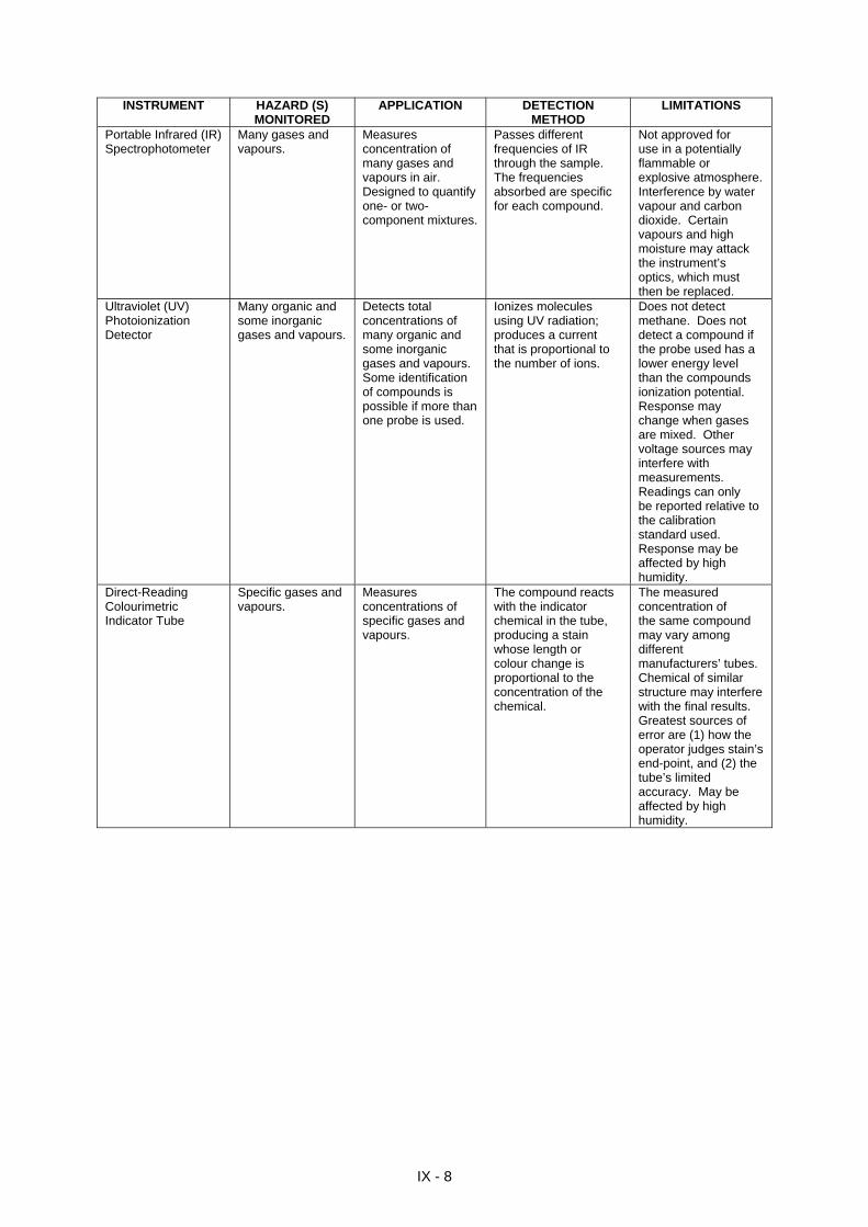
INSTRUMENT HAZARD (S)
MONITORED APPLICATION DETECTION
METHOD LIMITATIONS
Portable Infrared (IR) Spectrophotometer
Many gases and vapours.
Measures concentration of many gases and vapours in air. Designed to quantify one- or two-component mixtures.
Passes different frequencies of IR through the sample. The frequencies absorbed are specific for each compound.
Not approved for use in a potentially flammable or explosive atmosphere. Interference by water vapour and carbon dioxide. Certain vapours and high moisture may attack the instrument’s optics, which must then be replaced.
Ultraviolet (UV) Photoionization Detector
Many organic and some inorganic gases and vapours.
Detects total concentrations of many organic and some inorganic gases and vapours. Some identification of compounds is possible if more than one probe is used.
Ionizes molecules using UV radiation; produces a current that is proportional to the number of ions.
Does not detect methane. Does not detect a compound if the probe used has a lower energy level than the compounds ionization potential. Response may change when gases are mixed. Other voltage sources may interfere with measurements. Readings can only be reported relative to the calibration standard used. Response may be affected by high humidity.
Direct-Reading Colourimetric Indicator Tube
Specific gases and vapours.
Measures concentrations of specific gases and vapours.
The compound reacts with the indicator chemical in the tube, producing a stain whose length or colour change is proportional to the concentration of the chemical.
The measured concentration of the same compound may vary among different manufacturers’ tubes. Chemical of similar structure may interfere with the final results. Greatest sources of error are (1) how the operator judges stain’s end-point, and (2) the tube’s limited accuracy. May be affected by high humidity.
IX - 8
9. RESPONSE OPERATION TEAM STRUCTURE When dealing with any chemical emergency: i) approach with care; ii) identify the products; iii) assess the situation; and iv) use appropriate protective clothing. A response operation within an exclusion area should be regarded as a high priority risk operation and performed according to the scheme below (diagram). All adequate safety precautions must be taken.
IX - 9
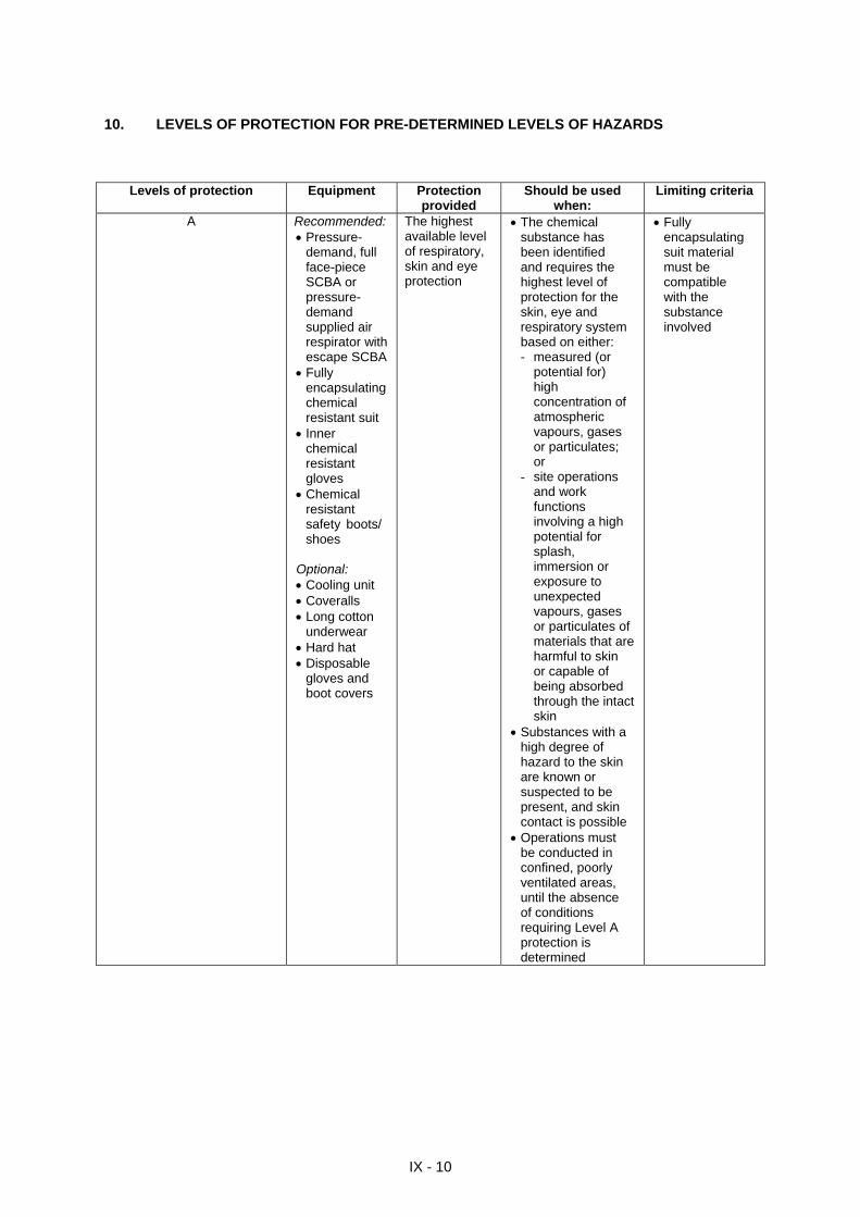
10. LEVELS OF PROTECTION FOR PRE-DETERMINED LEVELS OF HAZARDS
Levels of protection Equipment Protection provided
Should be used when:
Limiting criteria
A Recommended: Pressure- demand, full face-piece SCBA or pressure- demand supplied air respirator with escape SCBA Fully encapsulating chemical resistant suit Inner
chemical resistant gloves Chemical resistant safety boots/ shoes Optional: Cooling unit Coveralls Long cotton underwear Hard hat Disposable
gloves and boot covers
The highest available level of respiratory, skin and eye protection
The chemical substance has been identified and requires the highest level of protection for the skin, eye and respiratory system based on either: - measured (or potential for) high
concentration of atmospheric
vapours, gases or particulates; or
- site operations and work functions involving a high
potential for splash, immersion or exposure to unexpected vapours, gases or particulates of materials that are harmful to skin or capable of being absorbed through the intact skin Substances with a
high degree of hazard to the skin are known or suspected to be present, and skin contact is possible Operations must
be conducted in confined, poorly ventilated areas, until the absence of conditions requiring Level A protection is determined
Fully encapsulating suit material must be
compatible with the substance involved
IX - 10
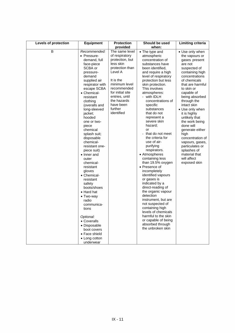
Levels of protection Equipment Protection provided
Should be used when:
Limiting criteria
B Recommended: Pressure-
demand, full face-piece SCBA or pressure- demand supplied air respirator with escape SCBA Chemical-
resistant clothing (overalls and
long-sleeved jacket;
hooded one or two- piece
chemical splash suit; disposable chemical- resistant one- piece suit) Inner and outer chemical- resistant
gloves Chemical- resistant
safety boots/shoes Hard hat Two-way
radio communica-tions
Optional: Coveralls Disposable
boot covers Face shield Long cotton underwear
The same level of respiratory protection, but less skin protection than Level A It is the minimum level recommended for initial site entries, until the hazards have been further identified
The type and atmospheric concentration of
substances have been identified, and require a high
level of respiratory protection but less skin protection.
This involves atmospheres: - with IDLH concentrations of specific
substances that do not represent a severe skin hazard; or
- that do not meet the criteria for
use of air- purifying
respirators. Atmospheres
containing less than 19.5% oxygen Presence of
incompletely identified vapours or gases is indicated by a direct-reading of the organic vapour detection
instrument, but are not suspected of containing high levels of chemicals harmful to the skin or capable of being
absorbed through the unbroken skin
Use only when the vapours or gases present
are not suspected of containing high concentrations
of chemicals that are harmful to skin or capable of being absorbed through the intact skin Use only when it is highly unlikely that the work being done will generate either high
concentration of vapours, gases, particulates or splashes of material that will affect exposed skin
IX - 11
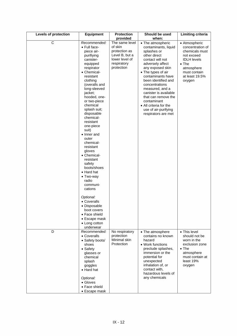
Levels of protection Equipment Protection provided
Should be used when:
Limiting criteria
C Recommended: Full face- piece air- purifiying canister- equipped respirator Chemical-
resistant clothing (overalls and
long-sleeved jacket; hooded, one- or two-piece chemical splash suit; disposable chemical- resistant one-piece suit) Inner and
outer chemical-resistant gloves
Chemical-resistant safety boots/shoes
Hard hat Two-way
radio communi-cations
Optional: Coveralls Disposable
boot covers Face shield Escape mask Long cotton underwear
The same level of skin protection as Level B, but a lower level of respiratory protection
The atmospheric contaminants, liquid
splashes or other direct contact will not adversely affect any exposed skin The types of air
contaminants have been identified and
concentrations measured, and a canister is available that can remove the contaminant All criteria for the use of air-purifying respirators are met
Atmospheric concentration of chemicals must not exceed IDLH levels The
atmosphere must contain at least 19.5% oxygen
D Recommended: Coveralls Safety boots/
shoes Safety
glasses or chemical splash goggles
Hard hat Optional: Gloves Face shield Escape mask
No respiratory protection Minimal skin Protection
The atmosphere contains no known hazard Work functions
preclude splashes, immersion or the potential for unexpected inhalation of, or contact with, hazardous levels of any chemicals
This level should not be worn in the exclusion zone
The atmosphere must contain at least 19% oxygen
IX - 12
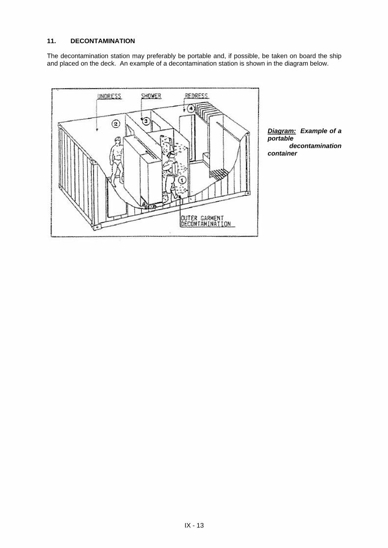
11. DECONTAMINATION The decontamination station may preferably be portable and, if possible, be taken on board the ship and placed on the deck. An example of a decontamination station is shown in the diagram below.
Diagram: Example of a portable
decontamination container
IX - 13
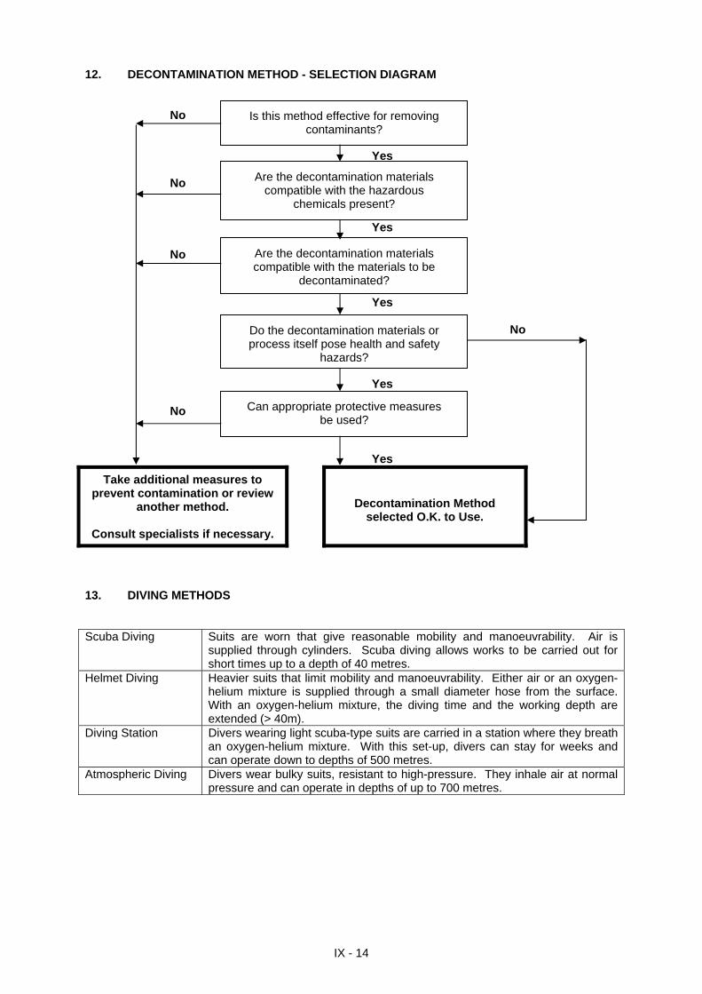
12. DECONTAMINATION METHOD - SELECTION DIAGRAM No
IX - 14
Yes No
Yes
No
Yes No
Yes
No
Yes
Take additional measures to prevent contamination or review
another method.
Consult specialists if necessary.
Decontamination Method selected O.K. to Use.
Is this method effective for removing contaminants?
Are the decontamination materials compatible with the hazardous
chemicals present?
Are the decontamination materials compatible with the materials to be
decontaminated?
Do the decontamination materials or process itself pose health and safety
hazards?
Can appropriate protective measures be used?
13. DIVING METHODS Scuba Diving Suits are worn that give reasonable mobility and manoeuvrability. Air is
supplied through cylinders. Scuba diving allows works to be carried out for short times up to a depth of 40 metres.
Helmet Diving Heavier suits that limit mobility and manoeuvrability. Either air or an oxygen-helium mixture is supplied through a small diameter hose from the surface. With an oxygen-helium mixture, the diving time and the working depth are extended (> 40m).
Diving Station Divers wearing light scuba-type suits are carried in a station where they breath an oxygen-helium mixture. With this set-up, divers can stay for weeks and can operate down to depths of 500 metres.
Atmospheric Diving Divers wear bulky suits, resistant to high-pressure. They inhale air at normal pressure and can operate in depths of up to 700 metres.
NOTE FOR THE CUSTOMS This document is produced and distributed free of charge by the Regional Marine Pollution Emergency Response Centre for the Mediterranean Sea (REMPEC), an office of the UNITED NATIONS, to its National Focal Points.
Issued and printed by the:
Regional Marine Pollution Emergency Response Centre for the Mediterranean Sea (REMPEC) Manoel Island, GZR 03 MALTA. Telex: 1464 UNROCC MW Telephone: +356 (-) 21 33 72 96 +356 (-) 21 33 72 97 +356 (-) 21 33 72 98 Telefax: +356 (-) 21 33 99 51 E-mail: [email protected] Website: www.rempec.org


![Chemical Spills [1]](https://img.pdfslide.us/doc/110x75/577ccfc91a28ab9e789093e1/chemical-spills-1.jpg)