Embed Size (px)
Citation preview
Regenerative Braking on Bicycles to Power LED Safety Flashers
by
Ian M. Collier
Submitted to the Department of Mechanical Engineering in Partial Fulfillment of theRequirements for the Degree of
Bachelor of Science
at the
Massachusetts Institute of Technology
June 2005
© 2005 Ian M. CollierAll rights reserved
MASSACHUSETTS INSTITUTEOF TECHNOLOGY
JUN 8 2005
LIBRARIES
The author hereby grants to MIT permission to reproduce and todistribute publicly paper and electronic copies of this thesis document in whole or in part.
Signature of Author......................................................................... ............................................Department of Mechanical Engineering
May 6, 2005
Certified by.. .................................................................................. ....... ..... ..... .............-David Wallace
Associate Professor of Mechanical EngineeringThesis Supervisor
Accepted by ..................................... .................................................................................................Ernest G. Cravalho
Chairman, Undergraduate Thesis Committee
.ARCHIVES
1

Regenerative Braking on Bicycles to Power LED Safety Flashers
by
Ian M. Collier
Submitted to the Department of Mechanical Engineeringon May 6, 2005 in Partial Fulfillment of the
Requirements for the Degree of Bachelor of Science inMechanical Engineering
Abstract
This work develops a method for capturing some of the kinetic energy ordinarily lost duringbraking on bicycles to power LED safety flashers. The system is designed to eliminate: (a)battery changing in popular LED flashers, and (b) the "generator drag" associated with battery-less human-powered bicycle lights and flashers. System sizing, mechanical designconsiderations, potential end-user factors, and a model for braking frequencies in urban settingsare discussed. With the urban commuter cyclist in mind as a potential user of the regenerativebraking system, custom direct-pull brake calipers (or "V-Brakes") were designed andmanufactured to include both conventional friction pads in addition to a DC motor to be used asa generator for kinetic energy capture.
The energy captured by the DC motor during braking is passed through a full wave bridge toa bank of Nickel-Cadmium batteries at an efficiency of 79%. The output of the full wave bridgeand the batteries are connected in parallel with a step-down switching voltage regulator, whichinsulates the LED safety flasher from voltage spikes due to braking at high cycling speeds.
The performance of the final prototype was evaluated at cycling speeds ranging from 8 to 19mph and braking frequencies ranging from 2 to 8 operations/stops per mile of travel. From themean power flow (charging) into the batteries per unit distance of travel and the power requiredby LED safety flashers, the effectiveness of the system at each speed and stopping frequency isexamined. For cyclists traveling at average speeds of 10 mph or higher, the LED safety flasherscan be powered continuously for stopping frequencies of 8 times per mile and semi-continuously(> 50% of the time) for stopping frequencies of at least 4 times per mile. As such, the system isdetermined to be potentially useful to urban commuter cyclists, who frequently perform brakingoperations at regularly spaced intersections and traffic signals, and who regularly travel bybicycle in low-light conditions (dawn or dusk), though usually less than 50% of the time.
Thesis Supervisor: David WallaceTitle: Associate Professor of Mechanical Engineering
2

Table of Contents
1. Introduction...............................................................................................................................5
2. System Design ........................................................................................................................... 72.1. The physics of braking ....................................................................................................... 72.2. Analysis of available energy..............................................................................................9
2.2.1. Characterization of braking operations for bicycle commuters .............................. 92.2.2. Average continuous power available during a city ride ........................................ 10
2.3. M otor sizing and selection...............................................................................................122.4. Energy storage..................................................................................................................13
3. Brake Caliper Design .............................................................................................................. 153.1. Design with a user focus .................................................................................................. 153.2. Iterative brake caliper design using CAD ........................................................................ 153.3. M anufacture of custom direct-pull brake calipers ......................................................... 17
4.. Testing ......................................................................................................................................204. 1. M easuring voltage and current flow during braking operations ...................................... 204.2. System efficiency and power analysis ............................................................................. 224.3. Evaluation of braking model............................................................................................25
5. Conclusions and discussion.....................................................................................................26
6.. References ................................................................................................................................286.1 . Cited references in order of appearance...........................................................................286.2. Additional references in alphabetical order .....................................................................29
3

Table of Figures
1.1 : Schematic of regenerative braking system for bicycles .......................................................... 5
2. 1.1 : Photo of direct-pull brake and lever......................................................................................7
2.1.2: Reaction forces at front and rear wheels during braking ...................................................... 8
2. 1.3: Diagram of a two-stage regenerative brake .......................................................................... 9
2.4.1: Schematic of energy storage circuit .................................................................................... 13
2.4.2: Voltage regulator circuit diagram ....................................................................................... 14
3.2.1: CAD model of regenerative braking system attached to existing brake caliper ................. 16
3.2.2: CAD model of concept including a custom brake caliper .................................................. 16
3..2',.3: CAD model of final prototype ............................................................................................ 17
32. 1: Photo of final brake caliper prototype from above ............................................................. 18
3.2a: Photo of final brake caliper prototype from the side ......................................................... 19
3 3.2b: Photo of final brake caliper prototype from the front ....................................................... 19
4. 1.1: Schematic of energy storage circuit with voltage and current probes for testing ............... 20
4.1.2: Plot showing the power consumption of PWM and continuous LED flasher modes ......... 21
4 1.3: Plot showing voltage and current of the motor and battery during braking ........................ 22
4.2.1: Plot of power flow out of the motor/generator and battery during braking ........................ 23
4.2.2: Plot of power flow out of the battery for braking at several initial speed values ............... 24
4
1. Introduction
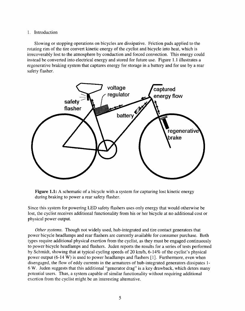
Slowing or stopping operations on bicycles are dissipative. Friction pads applied to therotating rim of the tire convert kinetic energy of the cyclist and bicycle into heat, which isirrecoverably lost to the atmosphere by conduction and forced convection. This energy couldinstead be converted into electrical energy and stored for future use. Figure 1.1 illustrates aregenerative braking system that captures energy for storage in a battery and for use by a rearsafety flasher.
Figure 1.1: A schematic of a bicycle with a system for capturing lost kinetic energyduring braking to power a rear safety flasher.
Since this system for powering LED safety flashers uses only energy that would otherwise belost, the cyclist receives additional functionality from his or her bicycle at no additional cost orphysical power output.
Other systems. Though not widely used, hub-integrated and tire contact generators thatpower bicycle headlamps and rear flashers are currently available for consumer purchase. Bothtypes require additional physical exertion from the cyclist, as they must be engaged continuouslyto power bicycle headlamps and flashers. Juden reports the results for a series of tests performedby Schmidt, showing that at typical cycling speeds of 20 km/h, 6-14% of the cyclist's physicalpower output (6-14 W) is used to power headlamps and flashers [1]. Furthermore, even whendisengaged, the flow of eddy currents in the armatures of hub-integrated generators dissipates 1-6 W. Juden suggests that this additional "generator drag" is a key drawback, which deters manypotential users. Thus, a system capable of similar functionality without requiring additionalexertion from the cyclist might be an interesting alternative.
5
Need for bicycle flashers. The urban bicycle commuter is susceptible to accidents and injurydue to the frequent necessity of riding with automobile traffic in low-visibility conditions.Bicycle-automobile accidents occur most frequently at intersections and drives, and account forthe vast majority of fatal bicycle accidents. A disproportionate number of such accidents occurduring low-light conditions, when fewer cyclists are on the road. A study completed by theJohns Hopkins Injury Prevention Center reports that the death rate per million bicycle trips is 8times greater between 10 PM and 1 AM than during the hours between 9 AM and 1 PM [2]. Toincrease night visibility and avoid collisions, most experts recommend the use of (flashing) lightsat the rear and front of the bicycle. However, according to a study reported on the MassachusettsBicycle Coalition's website by Osberg, Stiles, and Asare, only 15% of cyclists in Boston "wereobserved using either a headlight or taillight at night" [3].
In North America, highly efficient battery powered LED lighting systems such as those sold byCat Eye [4] are popular among commuters and are packaged to meet various power/lightintensity needs. Most common among this type are low-power models that conserve energy byflashing. High-power LEDs such as those offered by Luxeon [5] have recently become availablefor use as bright headlamps on bicycles. All such models are very compact and simple to operate.The only obvious drawback to these types is that they require an occasional change of batteries.
This work develops a consumer product concept for kinetic energy storage during brakingoperations to power popular LED safety flashers on bicycles. A system for energy recovery (DCmotor/generator) and storage (battery) is developed and implemented in the form of a functionalprototype, which requires no change of batteries. The actual efficiency and utility of the productare subsequently tested and compared with performance predictions. Finally, future generationsand directions for the concept are presented and discussed.
6
2. System Design
2.1. The physics of braking
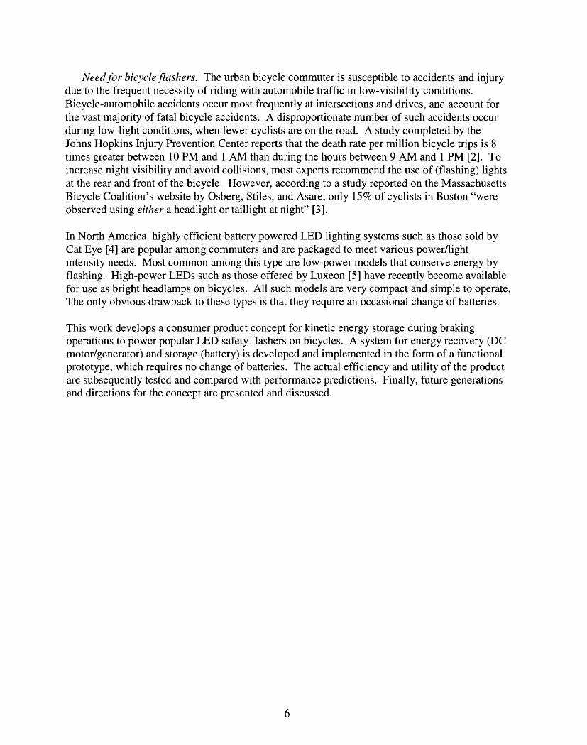
Bicycles are generally decelerated by the action of forcing a brake pad against the rim of thefront and/or rear wheel. Brake pads are typically made of a rubber-like material, which is chosenfor its high friction coefficient when incident with both dry and wet aluminum. A system oflever arms at the brake handle and the brake caliper provide a mechanism for greatly amplifyingthe braking force at the pad. Consider the direct-pull brakes of typical mountain bikes shownbelow in Fig. 2.1.1.
.X
Figure 2.1.1: Typical mountain bicycle direct-pull or "V-Brake" calipers andbrake handle.
The force applied by the fingers is amplified by lever arms at both the handle and the calipers toget the force of braking. This mechanical advantage allows the cyclist to easily apply forcessufficient at the brake pad-rim interface to lock the wheels. Additionally, bicycle tires are madeof rubber, which has a very high coefficient of friction on cement and asphalt. The result is thatdecelerations due to braking are usually limited by the location of the center of mass, not bywheel locking.
On bicycles, the center of mass of the bicycle and rider is located far above the wheel contactat the ground and between the two points of wheel contact with the ground. As a result, brakingoperations using either the front or rear wheel are limited by the reduction of the reaction force atthe rear wheel when the mass rapidly decelerates. During rear wheel braking, this results inskidding. In front wheel braking, the rear wheel can lift off of the ground entirely and the ridercan be thrown over the handlebars! This is due in part to the high coefficient of friction at thetire-road interface mentioned above.
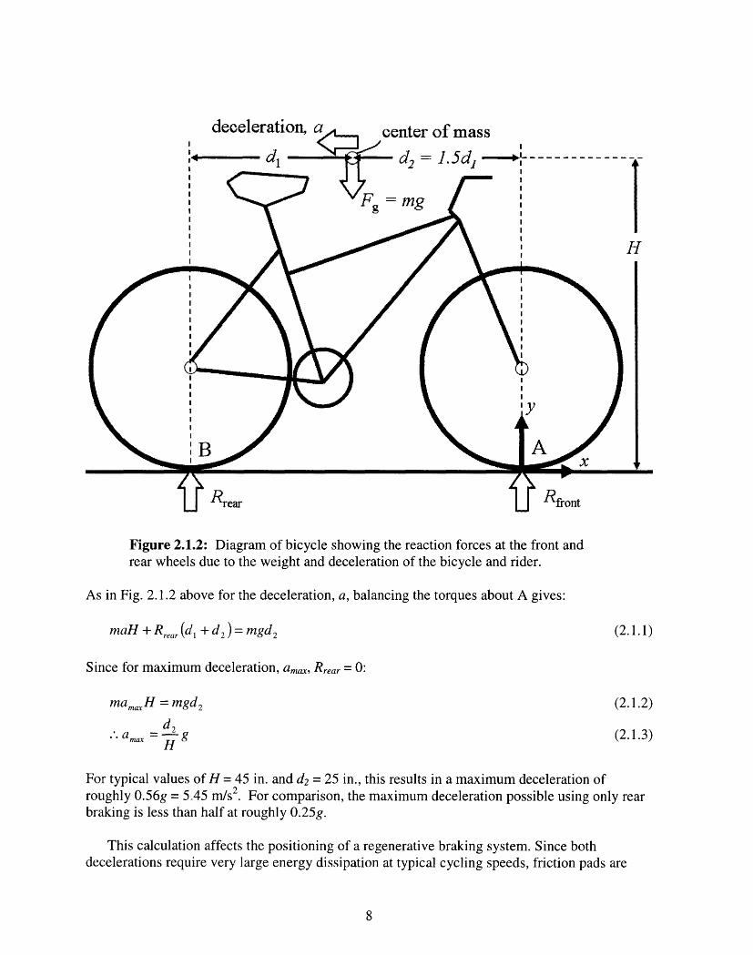
To understand the limits of possible decelerations on bicycles, consider the maximumdeceleration when the reaction force at the rear wheel contact goes to zero. Fig. 2.1.2 belowshows both reaction forces, Rfront and Rrear, for the wheel contacts as well as the approximatelocation of the center of mass (60% rear and 40% front for crouched cyclists) [6].
7
t�
A l~~~r~~ti(~~~n· tn
d2 = 1.5dj ::--
mg
/I\ ' H
Figure 2.1.2: Diagram of bicycle showing the reaction forces at the front andrear wheels due to the weight and deceleration of the bicycle and rider.
As in Fig. 2.1.2 above for the deceleration, a, balancing the torques about A gives:
mnaH + Rrear (d1 + d 2 ) = mgd 2 (2.1.1)
Since for maximum deceleration, am,, Rrear = 0:
nat maxH = mgd 2 (2.1.2)
.'.amax = Hg (2.1.3)H
For typical values of H = 45 in. and d2 = 25 in., this results in a maximum deceleration ofroughly 0.56g = 5.45 m/s2. For comparison, the maximum deceleration possible using only rearbraking is less than half at roughly 0.25g.
This calculation affects the positioning of a regenerative braking system. Since bothdecelerations require very large energy dissipation at typical cycling speeds, friction pads are
8
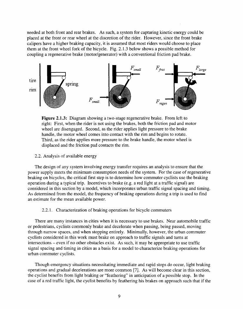
needed at both front and rear brakes. As such, a system for capturing kinetic energy could beplaced at the front: or rear wheel at the discretion of the rider. However, since the front brakecalipers have a higher braking capacity, it is assumed that most riders would choose to placethem at the front wheel fork of the bicycle. Fig. 2.1.3 below shows a possible method forcoupling a regenerative brake (motor/generator) with a conventional friction pad brake.
sprmng
Fsmala
Small
Figure 2.1.3: Diagram showing a two-stage regenerative brake. From left toright: First, when the rider is not using the brakes, both the friction pad and motorwheel are disengaged. Second, as the rider applies light pressure to the brakehandle, the motor wheel comes into contact with the rim and begins to rotate.Third, as the rider applies more pressure to the brake handle, the motor wheel isdisplaced and the friction pad contacts the rim.
2.2. Analysis of available energy
The design of any system involving energy transfer requires an analysis to ensure that thepower supply meets the minimum consumption needs of the system. For the case of regenerativebraking on bicycles, the critical first step is to determine how commuter cyclists use the brakingoperation during a typical trip. Incentives to brake (e.g. a red light at a traffic signal) areconsidered in this section by a model, which incorporates urban traffic signal spacing and timing.As determined from the model, the frequency of braking operations during a trip is used to findan estimate for the mean available power.
2.2.1. Characterization of braking operations for bicycle commuters
There are many instances in cities when it is necessary to use brakes. Near automobile trafficor pedestrians, cyclists commonly brake and decelerate when passing, being passed, movingthrough narrow spaces, and when stopping entirely. Minimally, however, the urban commutercyclists considered in this work must brake on approach to traffic signals and turns atintersections - even if no other obstacles exist. As such, it may be appropriate to use trafficsignal spacing and timing in cities as a basis for a model to characterize braking operations forurban commuter cyclists.
Though emergency situations necessitating immediate and rapid stops do occur, light brakingoperations and gradual decelerations are more common [7]. As will become clear in this section,the cyclist benefits from light braking or "feathering" in anticipation of a possible stop. In thecase of a red traffic light, the cyclist benefits by feathering his brakes on approach such that if the
9
tire
rim
I
ii
iii
I

light turns green, he may proceed through the intersection with a minimal loss of speed andkinetic energy.
2.2.2. Average continuous power available during a city ride
This section proposes a method for estimating the mean power available to supply LEDsafety flashers by assuming that a known fraction of the total kinetic energy of the bicycle andrider can be captured and stored by regenerative braking. The model considers typical cyclingspeeds, urban traffic signal spacing, and an equal probability of arriving at all times during thesignal cycle.
The energy available for capture and storage is simply the energy associated with a movingmass -- in this case, a bicycle and rider. Recall that the instantaneous kinetic energy, KE, of abicycle and rider of combined mass, m, at velocity, v, is shown in Eq. 2.2.1:
mv 2
2KE= 2.(2.2.1)If the cyclist were to use his or her brakes and come to a complete stop, this would be the totalenergy dissipated in that operation. More generally, the energy lost (or captured) in braking isdue to a change from initial velocity, vi, to a final (lower) velocity, Vf. From Eq. 2.2.1, theresulting change in energy, AKE, is:
AiKSE= 2 (Vf V (2.2.2)2
For a better understanding of how this applies to cycling, it is helpful to think of vi as typicalcruising velocity before braking and of Vf as a fraction of the cruising velocity. Describing thefinal velocity as a fraction,f< 1, of the initial velocity, the result is:
AKJE= _ v i(f2 -1). (2.2.3)
Note that AKE will always be negative - kinetic energy of the bicycle and rider is always lostduring braking operations.
Based upon ideas presented in the previous section, a simple model was developed toestimate the kinetic energy which could be captured during typical braking operations and usedto power LED safety flashers. The model assumes that cyclists must minimally use brakes whenapproaching red lights at major intersections. According to Prof. Peter Furth [8], since signals atmajor intersections in cities are not coordinated for bicycle traffic it is appropriate to assume thata cyclist will arrive at any given traffic signal at a random point in its (green-yellow-red) cycle.The duration of the red light is typically - 35 seconds, so for a typical 70 second, two-stagetraffic signal, the probability that a traffic signal will be red, Pred, on approach is simply the ratioof the "red time," t
read, to the total period of the traffic signal, Tsig:
10
red rt (2.2.4)'red = ~~ri
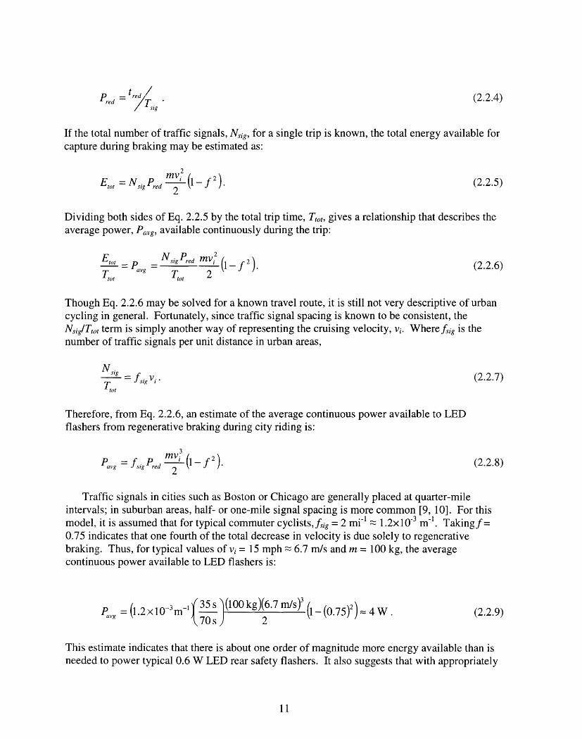
If the total number of traffic signals, Nsig, for a single trip is known, the total energy available forcapture during braking may be estimated as:
Etot = NsigPrd 2 (1 f 2) (2.2.5)
Dividing both sides of Eq. 2.2.5 by the total trip time, Ttot, gives a relationship that describes theaverage power, Pavg, available continuously during the trip:
E °=v Nsig Pred mv(2
t' = Pavg reT0 2 (1-f)(2.2.6)to tot 2
Though Eq. 2.2.6 may be solved for a known travel route, it is still not very descriptive of urbancycling in general. Fortunately, since traffic signal spacing is known to be consistent, theN'ig/Ttot term is simply another way of representing the cruising velocity, vi. Wherefsig is thenumber of traffic signals per unit distance in urban areas,
N sigN sig vi (2.2.7)Tot
Therefore, from Eq. 2.2.6, an estimate of the average continuous power available to LEDflashers from regenerative braking during city riding is:
Pavg = fsigPred 2 (1 f ) (2.2.8)
Traffic signals in cities such as Boston or Chicago are generally placed at quarter-mileintervals; in suburban areas, half- or one-mile signal spacing is more common [9, 10]. For thismodel., it is assumed that for typical commuter cyclists,fsig = 2 mi -1 1.2x10 -3 m- 1. Takingf=0.75 indicates that one fourth of the total decrease in velocity is due solely to regenerativebraking. Thus, for typical values of vi = 15 mph 6.7 m/s and m = 100 kg, the averagecontinuous power available to LED flashers is:
Pavg = (1.2x10⁻³m-j 3 5 s )(100kg)(6.7m/s) (0.75)2)=4W (2.2.9avg 70 s 2 4W(229
This estimate indicates that there is about one order of magnitude more energy available than isneeded to power typical 0.6 W LED rear safety flashers. It also suggests that with appropriately
11
high efficiencies for energy conversion and storage, powering 2.4 W high-power LEDheadlamps may also be feasible.
2.3. Motor sizing and selection
The conversion of kinetic mechanical energy to stored electrical energy requires a suitablemotor or generator. Ideally, the motor would be sized to capture all or most of the kinetic energyfor storage during a braking operation, such that dissipative friction brakes would not benecessary. However, this is simply not possible on bicycles, where size and weight are majorconstraints. For the worst-case scenario of maximum deceleration ( 0.5g, as from Sec. 2.1) athigh velocity (- 30 mph), the peak power, Ppeak, dissipated when the brakes are first engaged is:
Ppeak - mavi 7000 W. (2.3.1)
Generators capable of capturing all of this energy would be too large to mount on bicycle brakecalipers. For comparison, 7 kW generators are sold as standby power supplies to meet theenergy needs of small homes during power outages [11]! Since the power required for "hardbraking" is beyond the capabilities of small DC motors, dissipative friction brakes must be usedin combination with a regenerative system for the safety of the cyclist. Further, it should benoted that even feathered braking operations will not produce useful decelerations unless themotor is of sufficient power.
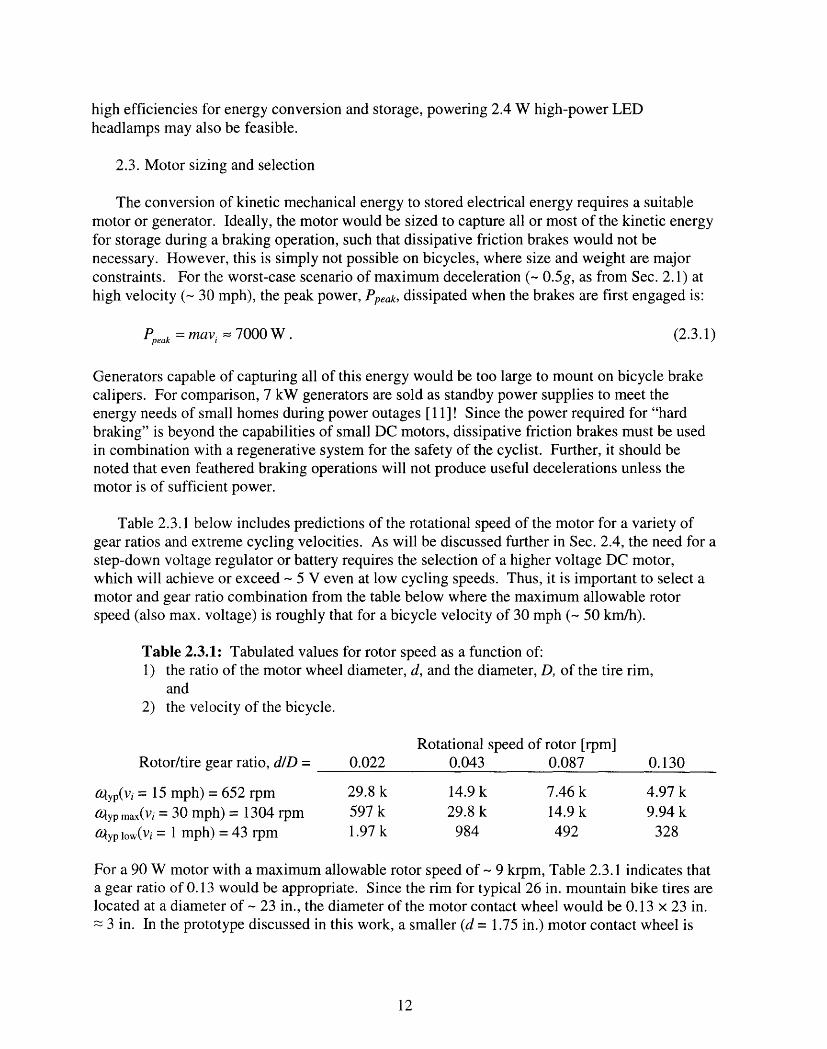
Table 2.3.1 below includes predictions of the rotational speed of the motor for a variety ofgear ratios and extreme cycling velocities. As will be discussed further in Sec. 2.4, the need for astep-down voltage regulator or battery requires the selection of a higher voltage DC motor,which will achieve or exceed - 5 V even at low cycling speeds. Thus, it is important to select amotor and gear ratio combination from the table below where the maximum allowable rotorspeed (also max. voltage) is roughly that for a bicycle velocity of 30 mph (- 50 km/h).
Table 2.3.1: Tabulated values for rotor speed as a function of:1) the ratio of the motor wheel diameter, d, and the diameter, D, of the tire rim,
and2) the velocity of the bicycle.
Rotational speed of rotor [rpm]Rotor/tire gear ratio, d/D = 0.022 0.043 0.087 0.130
atyp(vi = 15 mph)= 652 rpm 29.8 k 14.9 k 7.46 k 4.97 k
ypmax(Vi = 30 mph) = 1304 rpm 597 k 29.8 k 14.9 k 9.94 kNyp low(v/= 1 mph) = 43 rpm 1.97 k 984 492 328
For a 90 W motor with a maximum allowable rotor speed of- 9 krpm, Table 2.3.1 indicates thata gear ratio of 0.13 would be appropriate. Since the rim for typical 26 in. mountain bike tires arelocated at a diameter of - 23 in., the diameter of the motor contact wheel would be 0.13 x 23 in.
3 in. In the prototype discussed in this work, a smaller (d = 1.75 in.) motor contact wheel is
12
used to obtain greater power regeneration capacity at lower cycling speeds since mountain bikeused will not reach speeds of 30 mph.
In summary, proper motor selection will determine the effectiveness of the final system.Given the tight space constraints of bicycle brake calipers, it becomes important to choose amotor with the highest rated power so that braking operations will provide useful deceleration forthe cyclist. For both voltage regulation and battery charging, it will additionally be critical toselect a motor capable of exceeding the minimum "lockout" voltage and the charge thresholdvoltage, respectively. DC brush motors with rare earth magnets are widely available, whichfillfill all of the above requirements; they are ideal for this type of application.
Though slightly larger than desired, a 90 W Maxon RE 35 motor at 48 VDC was selected forreasons of availability. One benefit of choosing such a motor, however, is the complete lack of"cogging" effects common in cheap high-power DC brush motors, which tend to resist rotationof the motor shaft. This could cause the motor contact wheel to slip on the rim of the tire.
2.4. Energy storage
To store the energy captured by the motor/generator during braking, the system must includea bank of batteries or supercapacitors. In this work, because the primary focus is on themechanical design and a proof of concept, AA NiCd batteries were selected. Thoughsupercapacitors can accept energy at much higher rates when compared with batteries, any over-voltage would damage the supercapacitors. Rechargeable NiCd batteries are sufficient for thestorage needs of this work, cost less, and are less delicate.
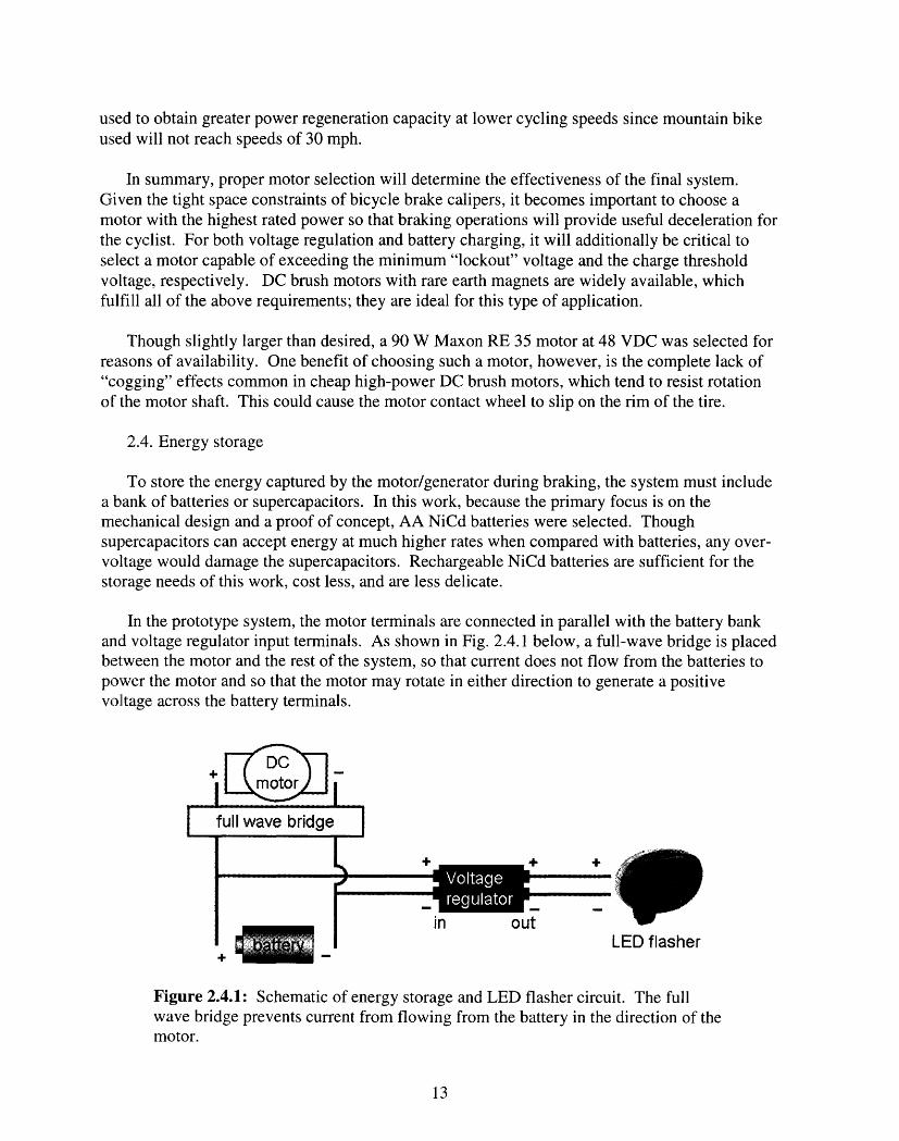
In the prototype system, the motor terminals are connected in parallel with the battery bankand voltage regulator input terminals. As shown in Fig. 2.4.1 below, a full-wave bridge is placedbetween the motor and the rest of the system, so that current does not flow from the batteries topower the motor and so that the motor may rotate in either direction to generate a positivevoltage across the battery terminals.
4-
4- I +_ _
in outLED flasher
Figure 2.4.1: Schematic of energy storage and LED flasher circuit. The fullwave bridge prevents current from flowing from the battery in the direction of themotor.
13

One limitation that arises from this setup is that no current will flow from the motor through thebridge if the voltage across the motor terminals is lower than the voltage of the battery bank.Since the Maxon RE 35 motor used in this work has a speed constant of 80.6 rpm/V and thevoltage across the NiCd battery bank is roughly 5.2 V, the motor will not charge the batteries forbicycle less than 0.73 mph.
The system must also include a way of converting the dynamically changing input voltagefrom the motor and batteries to supply a constant, low voltage to the LED safety flashers. Forthis purpose, a LM2575 adjustable step-down switching voltage regulator is used. The circuitdiagram used is shown below in Fig. 2.4.2. The feedback resistors RI and R2 were selected toprovide the LED flashers with a constant Vout = 3 V.
Figure 2.4.2: Circuit diagram for LM2575 step-down switching voltage regulatorused to protect the LED safety flashers from spikes in voltage from themotor/generator. R and R2 were selected such that the output, Vout = 3 V [12].
14

3. Brake Caliper Design
3.1. Design with a user focus
When choosing a design for a prototype regenerative braking system, it is necessary tounderstand the needs and habits of those commuter cyclists who might use such a system. Thefirst point to consider is that brake calipers are not consistent across different types of bicycles.Road bikes, for example, use different mounting hardware and mechanisms for braking than domountain bicycles. Since the regenerative braking system described by this work would be mosteffective in urban areas where braking is more frequent, the urban commuter cyclist is of primaryirnmportance.
The mountain bicycle is commonly used for city commutes due to its rugged design. Thefatter, treaded tires are less responsive than those of road bikes, but are better for jumping curbsor riding over potholes and through gravel. Except those with disc brakes installed, mountainbikes also have common brake mounting points at the backstays and front fork. These canaccommodate both cantilever brakes and direct-pull or V-Brakes. For the reasons above andbecause of availability, the prototype braking system in this work was designed to fit themounting points of standard mountain bikes.
The direct-pull geometry of Fig. 2.1.1 was chosen as a basis for the design of the calipersand friction pads, primarily because of their high mechanical advantage when compared tocantilever brakes. Also, for a motor as large as the Maxon RE 35 used in this work, the reducedangular rotation about the mounting point on the fork decreases the chance that the rear of themotor could impact the spokes of the wheel as the brake is released.
The emphasis on utilizing familiar brake geometry is intended to assist the potential users inunderstanding the function and utility of a regenerative braking system, which providesimproved safety (LED flasher) at no additional cost. Without the integration of a regenerativesystem with familiar friction brakes, the system could easily be confused at first glance with oneof the common wheel contact generators associated with increased physical effort and "generatordrag." This distinction is even more difficult to convey in the case of hub-integrated generators,which has a lower profile and no visible mechanical contact with the moving wheel. Ignoringthe drawbacks of eddy currents altogether, cyclists who do not understand the basic principles ofthermodynamics may not even consider the notion that the energy used to power lights andflashers results directly from increased physical effort on their part. One bicycle store clerkrefused to believe that hub-integrated generators contributed any drag whatsoever since the rotordoes not physically come into mechanical contact with the windings.
3.2. Iterative brake caliper design using CAD
Computer-aided drafting (CAD) techniques enabled the rapid visualization of multiple designconcepts, which provided the insight necessary for finalizing the prototype design. Manipulationof virtual components in the CAD environment elucidated the need for a completely new brakecaliper as well as the importance of maintaining several degrees of freedom for an adjustablemotor contact wheel.
15

Partly to improve the end user's understanding of how the system works, and partly to savetime, the design of the mechanical components of the system began with an effort to utilizepoints of attachment on existing, familiar bicycle brake calipers. Shown below in Fig. 3.2.1 is aconcept, which attaches to the brake caliper at the friction pad mount.
Figure 3.2.1: Design concept for attaching a motor for regenerative braking to anexisting brake caliper.
In this design as the brake caliper is engaged, the motor contact wheel touches the rim first. Asadditional force is supplied at the brake handle, the motor remains in contact with the rim, butallows a friction pad to bear against the rim through rotation about a pivot. The main problemwith this concept is that there are too few degrees of adjustability. It is clear even from thedrawing above that the motor contact wheel would not be tangent to the rim.
In a subsequent CAD exploration, a concept, which required the design of an entirely newbrake calipers was generated. As shown in Fig. 3.2.2, the concept includes a linear motion of themotor contact wheel. In the figure, a spring would be placed between the caliper itself and themotor contact wheel.
16
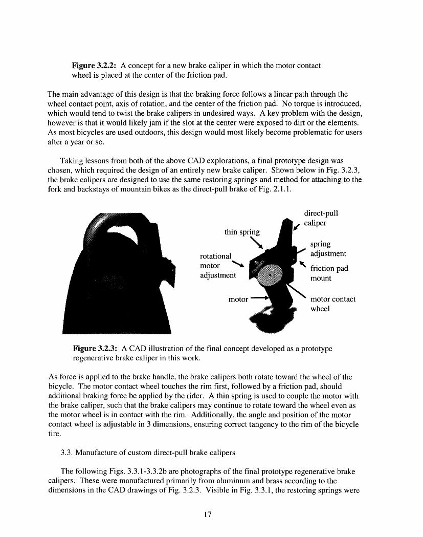
Figure 3.2.2: A concept for a new brake caliper in which the motor contactwheel is placed at the center of the friction pad.
The main advantage of this design is that the braking force follows a linear path through thewheel contact point, axis of rotation, and the center of the friction pad. No torque is introduced,which would tend to twist the brake calipers in undesired ways. A key problem with the design,however is that it would likely jam if the slot at the center were exposed to dirt or the elements.As most bicycles are used outdoors, this design would most likely become problematic for usersafter a year or so.
Taking lessons from both of the above CAD explorations, a final prototype design waschosen, which required the design of an entirely new brake caliper. Shown below in Fig. 3.2.3,the brake calipers are designed to use the same restoring springs and method for attaching to thefork and backstays of mountain bikes as the direct-pull brake of Fig. 2.1.1.
dilrect-pull
thin sp
rotationalmotor '%adjustment
moto]
, caliper
springadjustment
friction padmount
motor contactwheel
Figure 3.2.3: A CAD illustration of the final concept developed as a prototyperegenerative brake caliper in this work.
As force is applied to the brake handle, the brake calipers both rotate toward the wheel of thebicycle. The motor contact wheel touches the rim first, followed by a friction pad, shouldadditional braking force be applied by the rider. A thin spring is used to couple the motor withthe brake caliper, such that the brake calipers may continue to rotate toward the wheel even asthe motor wheel is in contact with the rim. Additionally, the angle and position of the motorcontact wheel is adjustable in 3 dimensions, ensuring correct tangency to the rim of the bicycletire.
3.3. Manufacture of custom direct-pull brake calipers
The following Figs. 3.3.1-3.3.2b are photographs of the final prototype regenerative brakecalipers. These were manufactured primarily from aluminum and brass according to thedimensions in the CAD drawings of Fig. 3.2.3. Visible in Fig. 3.3.1, the restoring springs were
17

formed from spheroidized air-hardening steel using v-brake restoring springs as a template.They were then hardened and tempered using a furnace to increase their springback and the bulkstiffness of the brake calipers. As noted below, an adjustment screw was placed to locate themotor contact wheel in the direction perpendicular to the bicycle tire plane.
Figure 3.3.1: View of brake calipers and motor/generator wheel from above.
Shown as dark gray in Fig. 3.2.3, but absent from the caliper at the left in Fig. 3.3.1 above, is afree-spinning wheel, which was designed to balance the force of the motor contact wheel. Inpractice, it was found to be unnecessary due to the much higher stiffness of the temperedrestoring springs.
Figs. 3.3.2a and 3.3.2b highlight some additional features and details of the prototype, whichare absent or different from the solid model of Fig. 3.2.3. Most notably, the profile of thecalipers was changed significantly from that of the CAD model to permit clearance of the tiretreads. Also important is the rubber o-ring for frictional contact with the aluminum rim of thebicycle wheel. A groove was cut on the circumference of the motor wheel to tightly fit astandard o-ring allowing for replacement in case of damage or wear.
18

Figure 3.3.2a: View of brake calipers andfront fork of bicycle from the side.
Figure 3.3.2b: View of brake calipers andfront fork of bicycle from the front.
The cantilevered spring coupling the motor with the brake caliper was cut on a water-jetcutting machine from 0.020 in. thick tempered steel sheet. The spring was designed to be verystiff in the direction of the fork to support the weight of the motor and somewhat compliant inthe perpendicular direction - allowing for rotation about the primary axis of the brake caliper.
19

4. Testing
4.1. Measuring voltage and current flow during braking operations
Shown below in Fig. 4.1.1 is a schematic of the prototype regenerative braking systemcomplete with instrumentation for measuring voltage and current.
R/10
R/10
1
+
Figure 4.1.1: Schematic of setup used for testing the regenerative braking system.Resistors were put in parallel with the ammeters to maintain current levels belowtheir rated value of 600 mA.
Since it was necessary to bring the bicycle up to normal cycling speeds during system tests, aremote method for data collection was necessary. Measurements of current and voltage from thearnmeters and voltmeters shown in Fig. 4.1.1 were recorded using a battery powered VernierLabPro® [13]. The use of the LabPro device restricted the types of voltage and current probes,which could be used. For example, the standard voltage and current probes were only rated for+/- 10 VDC and 600 mA, respectively. For the purpose of measuring higher currents, powerresistors were placed in parallel with the current probes as shown in the diagram above.
Prior to brake caliper testing, the voltage regulator and LED flasher circuit were connected tothe terminals of a lead-acid battery bank (different from the NiCd battery pack used otherwise) to
20
,r

obtain an idea of what the system. The power out of the battery is shown below in Fig. 4.1.2 forboth the pulse-width modulated (PWM) flashing mode and the continuous operation mode.
0.5
0.4
0iD©
0.3
0.2
0.1
0
0.0 0.5 1.0 1.5
Time (s)
2.0
Figure 4.1.2: Power out of a 4 V lead-acid battery during continuous and PWMflashing mode LED flasher operation. The peaks in power during the PWM modeare due to a switching "on" of the LEDs. It is important also to note that thepower does not go to zero between the peaks. Some of the remaining - 0.1 Wpowers the voltage regulator circuit.
During the testing of the prototype system, a Sigma Sport BC 500 Cycle Computer [14]positioned at the handle bar was used to visually monitor cycling speed on a liquid crystaldisplay. When the desired speed of each test was reached, the brakes were immediately applied.Two types of braking operations were performed along a straight course of travel at speedsranging from 8 mph to 19 mph:
1) motor wheel contact only, and2) a full stop at -0.2g deceleration.
Fig. 4.1.3 below shows data gathered for such a test at 15 mph. Note that during 1 < t < 3 sonly the motor wheel is in contact with the rim of the wheel and that the subsequent full stopoperation begins at t = 4.5 s.
21

/
6
5
4
3
2I-, 1tQ 0
o -1
-2
-3
-4
-5
-6'7
.1
2.5
2
1.5
1
0.5
0
-0.5 U
-1
-1.5
-2
-2.5
_'2
0 1 2 3 4 5 6 7 8 9 10 11 12 13 14 15
Time (s)
Figure 4.1.3: Plot of voltage and current as functions of time for several criticalpoints during two consecutive braking operations at 15 mph. A current flowingfrom the positive terminal of the motor (long dashed line) indicates braking. For1 s < t < 3 s, only the motor wheel was active and for 4.5 s < t < 10 s both thefriction pad and the motor wheel were brought into contact with the rim or the tire.
The sharp drop in current from 3 to 0 A following the feathered braking operation is due to therelease of the brake handle. A short release of the brake handle helped to distinguish separatebraking operations and to show that the restoring springs of the brake caliper were workingeffectively to allow rim contact only during braking operations.
Since testing was performed indoors on a 1/8-mile track, it became impossible at speeds > 15mph to feather the brakes, release the brake handle, and then complete a full stop all whilemaintaining a straight course. As such, at high speeds only a full stop braking operation wasperformed.
4.2. System efficiency and power analysis
The data from Fig. 4.1.3 were used to determine the flow of energy in the prototype systemfrom the motor to the batteries and from the batteries to the voltage regulator and LED safetyflasher. Using the familiar relationship for power P = VI in an electrical circuit, the power flow
22
-7 A n
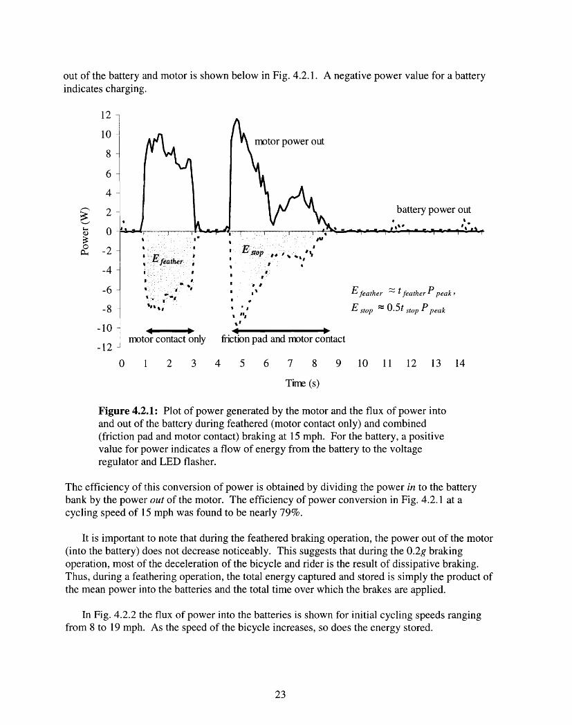
out of the battery and motor is shown below in Fig. 4.2.1. A negative power value for a batteryindicates charging.
motor power out
battery power out
-.
Efeather tfeather P peak,
E stop - 0.5t stop P peak
I �'U
E� 0�
* tI
I� *g
* I
, *,
a.I%I
4 -.Z b * ~~~ ~-NBmotor contact only friction pad and motor contact
0 1 2 3 4 5 6 7 8 9 10 11 12 13
Time (s)
Figure 4.2.1: Plot of power generated by the motor and the flux of power intoand out of the battery during feathered (motor contact only) and combined(friction pad and motor contact) braking at 15 mph. For the battery, a positivevalue for power indicates a flow of energy from the battery to the voltageregulator and LED flasher.
14
The efficiency of this conversion of power is obtained by dividing the power in to the batterybank by the power out of the motor. The efficiency of power conversion in Fig. 4.2.1 at acycling speed of 15 mph was found to be nearly 79%.
It is important to note that during the feathered braking operation, the power out of the motor(into the battery) does not decrease noticeably. This suggests that during the 0.2g brakingoperation, most of the deceleration of the bicycle and rider is the result of dissipative braking.Thus, during a feathering operation, the total energy captured and stored is simply the product ofthe mean power into the batteries and the total time over which the brakes are applied.
In Fig. 4.2.2 the flux of power into the batteries is shown for initial cycling speeds rangingfrom 8 to 19 mph. As the speed of the bicycle increases, so does the energy stored.
23
12
10
8
6
4
2
00
P-4 -2
-4
-6
-8
-10
-12

2
0
-2
· -4
-6
-8
-10
1'3-1z -
0 1 2 3 4 5 6 7 8 9 10
Tine (s)
Figure 4.2.2 Power flow out of the battery during braking operations for severalinitial cycling speeds. Negative power values indicate battery charging.
If is assumed that urban commuter cyclists travel at a nearly constant speed and stop withsomne frequency over their total travel distance, the mean power available, Pavailable, during acommute may be calculated. In Table 4.1.1, this estimate is obtained for several stoppingfrequencies and cycling speeds. In each instance, it is assumed that the cyclist comes to a fulland complete stop. The captured energy associated for each stop is 0.5tstopPpeak, as in Fig. 4.1.2.
Table 4.1.1: The dependence of the ratio of power in (Pavailable from braking) topower out (to LED flashers, Pflash = 0.18 W) on stopping frequency. Dark grayshading indicates cases where the system is capable of powering the LED flashercontinuously. Light gray shading indicates cases where the system is capable ofpowering the system > 50% of the time.
Cycling Energy stored per braking Pavailable/Pflash dependencespeed [mph] operation [J] on travel distance per full stop
1 s feathering full stop8 4 5.510 6 10.515 8 1419 8 20
24
The results tabulated above show that if the cyclist travels consistently at speeds greater than 10mph, LED safety flashers drawing 0.18 W from the motor and batteries can be powered:
1) continuously for stopping frequencies of at least 8 per mile, and2) semi-continuously for stopping frequencies of at least 4 per mile.
In other words, the commuter cyclist who travels only in low-light conditions would have toapply brake pressure about 8 times per mile, while a commuter who travels in low-light only50% of the time would have to apply brake pressure half as frequently. Thus, this system wouldwork well for a commuter in a city with 1/4-mile traffic signal spacing. If the commuter onlyneeded to turn on the LED flashers during a return trip in the evening, then the power needs ofthe flashers would be completely met by the brakes and the batteries would not need to bereplaced or recharged outside of the system.
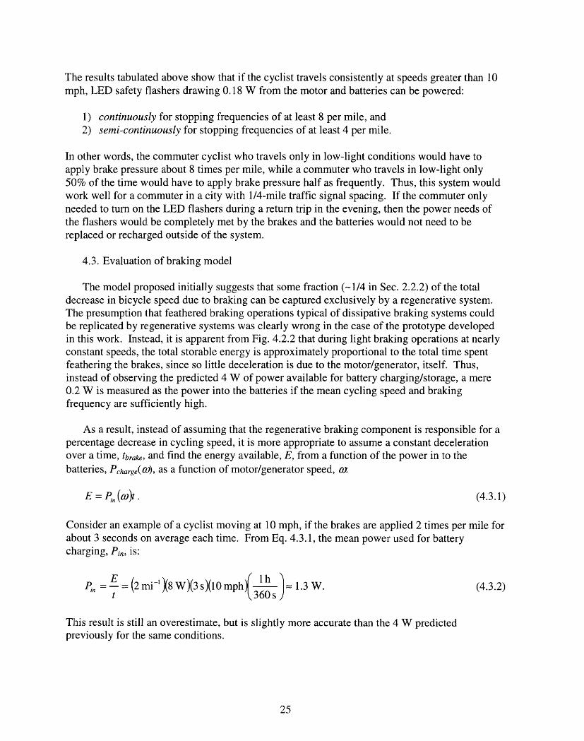
4.3. Evaluation of braking model
The model proposed initially suggests that some fraction (-1/4 in Sec. 2.2.2) of the totaldecrease in bicycle speed due to braking can be captured exclusively by a regenerative system.The presumption that feathered braking operations typical of dissipative braking systems couldbe replicated by regenerative systems was clearly wrong in the case of the prototype developedin this work. Instead, it is apparent from Fig. 4.2.2 that during light braking operations at nearlyconstant speeds, the total storable energy is approximately proportional to the total time spentfeathering the brakes, since so little deceleration is due to the motor/generator, itself. Thus,instead of observing the predicted 4 W of power available for battery charging/storage, a mere0.2 W is measured as the power into the batteries if the mean cycling speed and brakingfrequency are sufficiently high.
As a result, instead of assuming that the regenerative braking component is responsible for apercentage decrease in cycling speed, it is more appropriate to assume a constant decelerationover a time, tbrake, and find the energy available, E, from a function of the power in to thebatteries, Pharge(v), as a function of motor/generator speed, w.
E = Pn (o)t. (4.3.1)
Consider an example of a cyclist moving at 10 mph, if the brakes are applied 2 times per mile forabout 3 seconds on average each time. From Eq. 4.3.1, the mean power used for batterycharging, Pin, is:
Pi= E- =(2mi-'X8W)(3s)(10mph3- = 1.3W. (4.3.2)t 360s)
This result is still an overestimate, but is slightly more accurate than the 4 W predictedpreviously for the same conditions.
25

5, Conclusions and discussion
The current prototype. A novel method for powering LED safety flashers using regenerativebraking has been presented in this work. Custom direct-pull calipers were designed toaccommodate traditional friction pads and a DC motor/generator for the recovery of kineticenergy. In this way, the additional functionality of safety flashers has been added at no cost tothe cyclist. Throughout the course of normal cycling and braking, a battery bank powering theLED safety flashers is re-charged. This improves dramatically upon hub-integrated and wheelcontact generators, currently available, which drain up to 14% of the rider's total physical effortat typical cycling speeds.
While it has been shown that the total kinetic energy dissipated during normal brakingoperations is very large compared with the energy needed to power LED safety flashers, not allof it can be captured with small DC motors. Even the rather large 90 W motor used in this workdoes not contribute nearly enough deceleration to feel like dissipative friction braking. Such alarge motor or generator would be needed to feel such an effect that it would be impractical tomount on a bicycle. As such, it makes more sense to minimize the profile of the regenerativebrake and use the smallest motors with the greatest power density. DC brush motors with rareearth magnets rated for 30-40 W would be ideal. At cycling speeds up to 19 mph, only 14% ofthe capacity was utilized for the 90 W motor in this work.
The simple step-down voltage conversion circuit used to protect the LED flasher from over-voltage worked well for a motor with a speed constant of 80.6 rpm/V and a gear ratio of 1:14.For energy storage, cost-effective NiCd batteries had sufficient power density and were able tostore energy supplied by the motor at efficiencies near 79% on average.
The overall effectiveness of the regenerative braking system improves with increasingaverage cycling speed and with increasing stopping/braking frequency. For cyclists traveling atspeeds greater than 10 mph, the LED safety flashers will operate continuously for a stoppingfrequency of 8 times per mile and semi-continuously (> 50% of the time) for a stoppingfrequency of 4 times per mile. These conclusions support the design and development of thissystem specifically for use by urban commuters. Since some commuters regularly travel in low-light conditions less than 50% of the time, even semi-continuous LED flasher operation may besuitable in areas where braking is not as frequent.
Ideas for future development. The most obvious next step for development of the system asit stands would be to guard it against sand, gravel, and weather. Though the mechanicalcomponents of the system were designed to work well, even when covered in grease or dirt, themotor, voltage regulator circuit, and battery pack would need to be packaged to prevent damagefrom water. An injection molded casing with appropriate rubber seals or gaskets would probablybe sufficient. If a smaller, unsealed motor is used, additional protection would need to beconsidered to protect it against sand, grease, and water.
A second improvement, which would be needed for long battery life, is an appropriate chargecontroller. As is, the system does not guard against overcharging at all, which in the case ofNiCd batteries could cause damage to the cells and hazardous venting [ 15]. Another solution
26

would be to instead use supercapacitors to store energy. Though somewhat expensive, they havean even higher power density than the NiCd battery used in the prototype and are capable ofachieving efficiencies of nearly 90% - a - 10% improvement over the current efficiency. Fullycharged, two 50 F supercapacitors at 2.5 V would have enough energy to power 0.2 W LEDsafety flashers for nearly 26 minutes. Improving the efficiency in this way would improve thefunction of the regenerative braking system in areas where stopping frequency is less frequent.
27

6. References
6.1. Cited references in order of appearance
[1]] Juden, Chris. "Dynotest." Cycle Touring and Campaigning, Feb/Mar 1998. CyclistsTouring Club. Surrey, Great Britain. <http://www.myra-simon.com/bike/dynotest.html>
[2] "Injuries to Bicyclists" From a monograph by the Johns Hopkins Injury PreventionCenter Sponsored by the Snell Memorial Foundation.<http://www.smf.org/articles/injury.html>
[3] "Bicycle Crash Statistics." Massachusetts Bicycle Coalition. 2002.<http://www.massbike.org/infol/stats.htm>
[4] Cat Eye Home Page. Cat Eye Co. Inc. 2004. <http://www.cateye.com/en/index.php>
[5] Luxeon Product Home Page. Lumileds Lighting, L.L.C. 2005.<http://www.luxeon.com/products/>
[6] Wilson, David Gordon. Bicycling Science. 3 ed. Chapter 7: Braking. pp. 237-261.Cambridge: MIT Press, 2004.
[7] Forester, John. Effective Cycling. 6 ed. pp. 205-208, 378-387. Cambridge: MIT Press,2001.
[8] Furth, Peter. Chair, Department of Civil & Environmental Engineering, NortheasternUniversity. 15 Feb., 2005.
[9] "Access Management." Issue Brief 13. U.S. Department of Transportation FederalHighway Administration and the Institute of Transportation Engineers. Apr., 2004.<www.ite. org/library/IntersectionSafety/access.pdf>
[10] Levinson, Herbert S. "Street Spacing and Scale." Urban Street Symposium ConferenceProceedings. Dallas, TX. Jun. 28-30, 1999.<http://www.mackblackwell.org/research/finals/arc9012/streetspacing.pdf>
[11] 7,000 Watt Automatic Home Standby Generator System. Briggs & Stratton ProductCatalog. Briggs & Stratton Power Products. 2004.<http://www.standbygeneratorsystems.com/products/7kw.cfm>
[12] "1-A Simple Step-Down Switching Voltage Regulator." Texas Instruments. April 2005.<http://focus.ti.com/lit/ds/symlink/lm2575-33.pdf>
[13] Vernier LabPro User's Guide.Vernier Software & Technology. 2000.
28
[14] Sigma Sport US Home Page. Sigma Sport Germany. 2005.<http://www.sigmasport.com/index_usa.html>
[15] "Nickel Cadmium Application Manual." Moltech Power Systems, Inc. 2000.<http://www.moltechpower.com/techdata/appmanuals/NiCdApplication_Manual.htm>
6.2. Additional references in alphabetical order
"A Compendium of Statistics from Various Sources." Bicycle Helmet Safety Institute. 25 Mar.,2005. <http://www.bhsi.org/stats.htm>
Ballantine, Richard. Richard's 2lSt-Century Bicycle Book. pp. 33-34. New York: Overlook Press,2001.
"13Bicycle Lighting.." Wikipedia. 31 Mar., 2005. <http://en.wikipedia.org/wiki/Bicyclelighting>
Kifer, Ken. "How to Avoid Traffic Accidents." Ken Kifer's Bike Pages. 1999.<lttp://www.kenkifer.com/bikepages/traffic/accident.htm>
"Police Safety Tips and Information." City of Auburn, Indiana Home Page. 2004.<lhttp:#lwww.ci.auburn.in.us/departments/police/safetytips/>
29
![[PPT]Regenerative Braking Systems and their functions · Web viewHow Does Regenerative Braking Work? Regular brakes waste large amounts of useable energy6 Regenerative Braking systems](https://img.pdfslide.us/doc/110x75/5ae8634b7f8b9aee078f7805/pptregenerative-braking-systems-and-their-functions-viewhow-does-regenerative.jpg)
![REGENERATIVE BRAKING SYSTEM IN ELECTRIC VEHICLES · REGENERATIVE BRAKING SYSTEM IN ELECTRIC VEHICLES ... REGENERATIVE BRAKING SYSTEM ... Regenerative action during braking[9]](https://img.pdfslide.us/doc/110x75/5adccef67f8b9a1a088c7cf0/regenerative-braking-system-in-electric-vehicles-braking-system-in-electric-vehicles.jpg)