Embed Size (px)
Citation preview

FPI FIREPLACE PRODUCTS INTERNATIONAL LTD. 6988 Venture St., Delta, BC Canada, V4G 1H4919-625d 07.23.18
Tested by:
Installer: Please complete the details on the back cover and leave this manual with the homeowner.
Homeowner: Please keep these instructions for future reference.
www.regency-fire.com
- Do not store or use gasoline or other flammable vapors and liquids in the vicinity of this or any other appliance.
- WHAT TO DO IF YOU SMELL GAS • Do not try to light any appliance. • Do not touch any electrical switch: do not use any phone in your building. Leave the building immediately. • Immediately call your gas supplier from a neighbour's phone. Follow the gas supplier's
instructions. • If you cannot reach your gas supplier, call the fire department. - Installation and service must be performed by a qualified installer, service agency or the gas supplier.
WARNINGFIRE OR EXPLOSION HAZARDFailure to follow safety warnings exactly could result in seriousinjury, death, or property damage.
Regency Ultimate™ U900EGas Fireplace
Owners & Installation Manual
MODELS: U900E-NG Natural Gas U900E-LP Propane

2 | Regency Ultimate™ U900E Gas Fireplace
This appliance is only for use with the type of gas indicated on the rating plate. This appliance is not convertible for use with other gases unless a certified kit is used.
This appliance may be installed as an OEM installation in a manufactured home (USA only) or mobile home and must be installed in accordance with the manufacturer's instruction and the Manufactured Home Construction and Safety Standard, Title 24 CFR, Part 3280, in the Untied States, or the Standard for Installation in Mobile Homes, CAN/CSA Z240 MH, in Canada.
MANUFACTURED MOBILE HOME REQUIREMENTSINFORMATION FOR MOBILE/MANUFACTURED HOMES AFTER FIRST SALE
This Regency® product has been tested and listed by Warnock Hersey/Intertek as a Direct Vent Wall Furnace to the following standards: VENTED GAS FIREPLACE HEATERS ANSI Z21.88-2014 / CSA 2.33-2014 and GAS-FIRED APPLIANCES FOR USE AT HIGH ALTITUDES CAN / CGA 2.17-M91.
This appliance may only be installed in an aftermarket permanently located, manufactured home (U.S.A only) or mobile home, where not prohibited by local codes.
This Direct Vent System Appliance must be installed in accordance with the manufacturer's installation instructions and the Manufactured Home Construction and Safety Standard, Title 24 CFR, Part 3280, or the current Standard of Fire Safety Criteria for Manufactured Home Installations, Sites, and Communities ANSI/NFPA 501A, and with CAN/CSA Z240-MH Mobile Home Standard in Canada.
This appliance installation must comply with the manufacturer's installation instructions and local codes, if any. In the absence of local codes follow the current National Fuel Gas Code, ANSI Z223.1 and the current National Electrical Code ANSI/NFPA 70 in the U.S.A., and the current CAN/CGA B149 Gas Installation Code and the current Canadian Electrical Code CSA C22.1 in Canada.
This appliance comes equipped with a dedicated #8 Ground Lug for attachment of the ground wire to the steel chassis as applicable to local codes.
The appliance, when installed, must be electrically grounded in accordance with local codes or, in the absence of local codes, with the National Electrical Code, ANSI/NFPA 70, or the Canadian Electrical Code, CSA C22.1.
Ensure that structural members are not cut or weakened during installation.

Regency Ultimate™ U900E Gas Fireplace | 3
To the New Owner:
Congratulations! You are the owner of a state-of-the-art Gas Fireplace by REGENCY®. The U900E has been designed to provide you with all the warmth and charm of a fireplace at the flick of a switch. The model U900E has been approved by Warnock Hersey/Intertek for both safety and efficiency. As it also bears our own mark, it promises to provide you with economy, comfort and security for many trouble free years to follow. Please take a moment now to acquaint yourself with these instructions and the many features of your Regency® Fireplace.

4 | Regency Ultimate™ U900E Gas Fireplace
table of contents
Installation Copy of Safety Decal .....................................................5MA Code - CO Detector ................................................6Important Message ......................................................8Before You Start .............................................................8General Safety Information ............................................8Installation Checklist ......................................................9Locating Your Gas Fireplace ..........................................9Heatwave Duct System .................................................9Clearances ..................................................................10Mantel Clearances .......................................................11Mantel Leg Clearances ................................................11Unit Assembly Prior To Installation ..............................12
Nailing Strips........................................................12Installation Access panel .....................................12
Framing Dimensions ....................................................13Optional Framing kit .....................................................14Horizontal vent deflector installation ............................15Wall mount On / Off Switch and battery holder installation-required for all installations .......................16Non-Combustible Requirements..................................17Non-combustible facing installation ............................17Framing & Finishing .....................................................18Exterior Vent Termination Requirements .....................20Vent Restrictor Setting .................................................21Venting .........................................................................22
Direct Vent System (Flex) ..................................224” x 6-5/8” Rigid Pipe ..................................................23Cross Reference Chart only ........................................23
Rigid Pipe Venting Systems .................................25Venting Introduction .....................................................26Venting Arrangement for Horizontal Terminations .......26Venting Arrangement for Vertical Terminations ............27Vertical Termination - Co-linear Flex System into a masonry chimney .......................................................30Venting Arrangements - Vertical Termination ...............31Unit Installation with Horizontal Termination ...............324" x 6-5/8" venting .......................................................32Unit Installation with Horizontal Termination ...............33Dura-Vent Horizontal terminations ...............................34Unit installation with Vertical Termination .....................354" x 6-5/8" venting .......................................................35
Vertical Termination - 4'' x 6-7/8'' Venting (Part#946-755) .....................................................................................36Flex vent components ..................................................37High Elevation ..............................................................38Gas Line Installation ....................................................38Pilot Adjustment ...........................................................38Gas Pipe Pressure Testing ..........................................38885 S.I.T. Valve Description .........................................38Aeration Adjustment ....................................................39Wiring Diagram ............................................................40Log set installation .......................................................41Front trim removal / Installation ...................................43Inner panel removal / Installation .................................43Screen & inner Door frame Installation ........................44Glass surround installation ..........................................45Optional finishing trim installation ................................45Faceplate installation ...................................................46First Fire ......................................................................47
Operating InstructionsOperating Instructions .................................................47Coding/Pairing of remote control transmitter with on/off switch .......................................47Lighting Procedure ......................................................48Shutdown Procedure ...................................................48Copy of the Lighting Plate Instructions .......................49Proflame II Remote Control Operating Instructions 50-53Normal Operating Sounds of Gas Appliances .............54
MaintenanceMaintenance Instructions ............................................54Glass Gasket ...............................................................55Glass Door ...................................................................55
Glass Replacement .............................................55General Vent Maintenance ..........................................55Fan Service .................................................................57Glass door removal .....................................................57Valve Tray Replacement ..............................................58
PartsMain Assembly ............................................................59Accessories .................................................................61
WarrantyWarranty ......................................................................62

Regency Ultimate™ U900E Gas Fireplace | 5
safety decalThis is a copy of the label that accompanies each U900E-NG and U900E-LP Direct Vent Gas Fireplace. We have printed a copy of the contents here for your review.
NOTE: Regency® units are constantly being improved. Check the label on the unit and if there is a difference, the label on the unit is the correct one.
COPY OF SAFETY DECAL
For the State of Massachusetts, installation and repair must be done by a plumber or gasfitter licensed in the Commonwealth of Massachusetts.
For the State of Massachusetts, flexible con-nectors shall not exceed 36 inches in length.
For the State of Massachusetts, the appli-ances individual manual shut-off must be a t-handle type valve.
The State of Massachusetts requires the installation of a carbon monoxide alarm in accordance with NFPA 720 and a CO alarm with battery back up in the same room where the gas appliance is installed.
Part #: 919-624
Colour: Black on grey except what is indicated as being printed red.Size: (File at 100%) 9.3"w x 5.9"hMaterial: 2 ml silver matt polyester (DPM SMS)
Dec 14/15: Created draftFeb 24/16: UpdatedMar. 10/16: Updated Heatwave kit part #
DO NOT REMOVE THIS LABEL / NE PAS ENLEVER CETTE ÉTIQUETTE
443
443
DOOR SEAL: Please check that the door is
properly sealed
FPI Fireplace Products International Ltd. Delta, BC, Canada
Minimum Clearances to Combustibles /Dégagement minimum des matériaux combustibles
Serial No./ No de Série
919-624
MAY BE INSTALLED IN MANUFACTURED (MOBILE) HOMES AFTER FIRST SALE.
Listed/Nom: VENTED GAS FIREPLACE HEATER / FOYER AU GAZ À ÉVACUATIONCertified for/Certifi e pour: CANADA and U.S.A.éTested to: CAN/CGA-2.17-M91(R2009)
ANSI Z21.88-2014Conforms to:CSA 2.33-2014Certified to:
Electrical supply / Électrique 115VAC, 1.13 A, 60Hz.Fan Part # 910-157/P
Made in Canada/ Fabriqué au Canada
Duplicate S/N
(See Instruction Manual for detailed instructions)
(Voir Manuel pour plus de détails)
APPAREIL FONCTIONNANT AU GAZ PROPANECONÇU POUR FOYER : Modèle U900E-LP
PROPANE GAS: Model U900E-LP
NATURAL GAS: Model U900E-NG
Minimum supply pressureManifold pressure - HighManifold pressure - LowOrifice sizeMaximum inputMinimum inputAltitude
APPAREIL FONCTIONNANT AU GAZ NATUREL CONÇU POUR FOYER : Modèle U900E-NG
5.0" WC/C.E. (1.25 kPa)3.5" WC/C.E. (0.87 kPa)1.6" WC/C.E. (0.40 kPa)# 35 DMS 34,000 Btu/h (9.96 kW)23,500 Btu/h (6.89 kW)0-4500 ft/pi (0-1372 m)
11“ WC (2.73 kpa)10" WC/C.E. (2.49 kPa)6.4" WC/C.E. (1.60 kPa)# 52 DMS 31,500 Btu/h (9.23kW)25,000 Btu/h (7.33 kW)0-4500 ft/pi (0-1372 m)
Minimum supply pressureManifold pressure - HighManifold pressure - LowOrifice sizeMaximum inputMinimum inputAltitude
D
E
F
A
B
C
Side Walls / Murs latérauxA 8” (203 mm)Ceiling / PlafondB 48” (1219 mm)Min. Mantel Height /Hteur Min ManteauC 20" (508 mm)Max. Mantel Depth/Profondeur Max ManteauD 12” (305 mm) Alcove Width/Largeur AlcôveE 84" (1524 mm)Alcove Depth/Profondeur AlcôveF 36" (2134 mm)
This appliance must be installed in accordance with local codes, if any; if none, follow the National Fuel Gas Code, ANSI Z223.1, or Natural Gas and Propane Installation Code, CSA B149.1.This appliance must be installed in accordance with the Standard CAN/CSA Z240 MH, Mobile Housing, in Canada, or with the Manufactured Home Construction and Safety Standard, Title 24 CFR, Part 3280, in the United States, or when such a standard is not applicable, ANSI/NCSBCS A225.1/NFPA 501A, Manufactured Home Installations Standard or ANSI A119.2 ou NFPA 501C Standard for Recreational VehiclesThis appliance is only for use with the type(s) of gas indicated on the rating plate and may be installed in an aftermarket, permanently located, manufactured home (USA only) or mobile home, where not prohibited by local codes. See owner's manual for details. This appliance is supplied with a conversion kit.L'appareil doit être installé conformément aux codes et règlements locaux, ou, en l'absence de tels règlements, selon les codes d'installation National Fuel Gas Code ANSI Z223.1, ou CSA-B149.1 Natural Gas and Propane Installation Code en vigueur.L'appareil doit être installé conformément à la norme CAN/CSA-Z240, Série MM, Maisons mobiles ou CAN/CSA-Z240 VC, Véhicules de camping, ou la norme 24 CFR Part 3280, Manufactured Home Construction and Safety Standard. Si ces normes ne sont pas applicables, veuillez vous référer à la norme ANSI/NCSBCS A225.1/NFPA 501A, Manufactured Home Installations Standard, ou ANSI A119.2 ou NFPA 501C Standard for Recreational Vehicles.Cet appareil doit être utilisé uniquement avec les types de gaz indiqués sur la plaque signalétique et peut être installé dans une maison préfabriquée (É.-U. seulement) ou mobile installée à demeure si les règlements locaux le permettent. Voir la notice de l'utilisateur pour plus de renseignements. Une trousse de conversion est fournie avec cet appareil.f si une trousse de conversion certifiée est fournie.
4001172
For Use Only with Barrier (Part # 466-111) Follow installation instructions. Utiliser uniquement avec l’écran (n °466-111). Suivre les instructions d'installation.
Pression d'allimentation minimumPression de sortie (manifold) - HautePression de sortie (manifold) - BasseTaille de l’orificeD bit Calorifique maximum éD bit Calorifique minimuméAltitude
Pression d'allimentation minimumPression de sortie (manifold) - HautePression de sortie (manifold) - BasseTaille de l’orificeD bit Calorifique maximuméD bit Calorifique minimuméAltitude
VENTED GAS FIREPLACE HEATER - NOT FOR USE WITH SOLID FUELS. NE PAS UTILISER AVEC UN COMBUSTIBLE SOLIDE. FOYER AU GAZ À ÉVACUATION -
Part No. 946-753 register kit may be used. La trousse de registre (no.de pièce 946-753 ) peut être utilisée.

6 | Regency Ultimate™ U900E Gas Fireplace
requirements
5.08: Modifications to NFPA-54, Chapter 10
(2) Revise 10.8.3 by adding the following additional requirements:
(a) For all side wall horizontally vented gas fueled equipment installed in every dwelling, building or structure used in whole or in part for residential purposes, including those owned or operated by the Commonwealth and where the side wall exhaust vent termination is less than seven (7) feet above finished grade in the area of the venting, including but not limited to decks and porches, the following requirements shall be satisfied:
1. INSTALLATION OF CARBON MONOXIDE DETECTORS. At the time of installation of the side wall horizontal vented gas fueled equipment, the installing plumber or gasfitter shall observe that a hard wired carbon monoxide detector with an alarm and battery back-up is installed on the floor level where the gas equipment is to be installed. In addition, the installing plumber or gasfitter shall observe that a battery operated or hard wired carbon monoxide detector with an alarm is installed on each additional level of the dwelling, building or structure served by the side wall horizontal vented gas fueled equipment. It shall be the responsibility of the property owner to secure the services of qualified licensed professionals for the installation of hard wired carbon monoxide detectors
a. In the event that the side wall horizontally vented gas fueled equipment is installed in a crawl space or an attic, the hard wired carbon monoxide detector with alarm and battery back-up may be installed on the next adjacent floor level.
b. In the event that the requirements of this subdivision can not be met at the time of completion of installation, the owner shall have a period of thirty (30) days to comply with the above requirements; provided, however, that during said thirty (30) day period, a battery operated carbon monoxide detector with an alarm shall be installed.
2. APPROVED CARBON MONOXIDE DETECTORS. Each carbon monoxide detector as required in accordance with the above provisions shall comply with NFPA 720 and be ANSI/UL 2034 listed and IAS certified.
3. SIGNAGE. A metal or plastic identification plate shall be permanently mounted to the exterior of the building at a minimum height of eight (8) feet above grade directly in line with the exhaust vent terminal for the horizontally vented gas fueled heating appliance or equipment. The sign shall read, in print size no less than one-half (1/2) inch in size, "GAS VENT DIRECTLY BELOW. KEEP CLEAR OF ALL OBSTRUCTIONS".
4. INSPECTION. The state or local gas inspector of the side wall horizontally vented gas fueled equipment shall not approve the installation unless, upon inspection, the inspector observes carbon monoxide detectors and signage installed in accordance with the provisions of 248 CMR 5.08(2)(a)1 through 4.
(b) EXEMPTIONS: The following equipment is exempt from 248 CMR 5.08(2)(a)1 through 4:
1. The equipment listed in Chapter 10 entitled "Equipment Not Required To Be Vented" in the most current edition of NFPA 54 as adopted by the Board; and
2. Product Approved side wall horizontally vented gas fueled equipment installed in a room or structure separate from the dwelling, building or structure used in whole or in part for residential purposes.
(c) MANUFACTURER REQUIREMENTS - GAS EQUIPMENT VENTING SYSTEM PROVIDED. When the manufacturer of Product Approved side wall horizontally vented gas equipment provides a venting system design or venting system components with the equipment, the instructions provided by the manufacturer for installation of the equipment and the venting system shall include:
1. Detailed instructions for the installation of the venting system design or the venting system components; and
2. A complete parts list for the venting system design or venting system.
(d) MANUFACTURER REQUIREMENTS - GAS EQUIPMENT VENTING SYSTEM NOT PROVIDED. When the manufacturer of a Product Approved side wall horizontally vented gas fueled equipment does not provide the parts for venting the flue gases, but identifies "special venting systems", the following requirements shall be satisfied by the manufacturer:
1. The referenced "special venting system" instructions shall be included with the appliance or equipment installation instructions; and
2. The "special venting systems" shall be Product Approved by the Board, and the instructions for that system shall include a parts list and detailed installation instructions.
(e) A copy of all installation instructions for all Product Approved side wall horizontally vented gas fueled equipment, all venting instructions, all parts lists for venting instructions, and/or all venting design instructions shall remain with the appliance or equipment at the completion of the installation.
MA Code - CO Detector(for the State of Massachusetts only)

Regency Ultimate™ U900E Gas Fireplace | 7
dimensions
ALL PICTURES / DIAGRAMS SHOWN THROUGHOUT THIS MANUAL ARE FOR ILLUSTRATION PURPOSES ONLY.ACTUAL PRODUCT MAY VARY DUE TO PRODUCT ENHANCEMENTS.
Outer Faceplate size - 43-1/16" W x 25-14" HGlass Surround size - 47" W x 25-1/4" HFinishing Trim (Clean Edge Design) size - 40-1/4" W x 18-7/8" H

8 | Regency Ultimate™ U900E Gas Fireplace
installation
3. See general construction and assembly instructions. The appliance and vent should be enclosed.
4. This appliance must be connected to the specified vent and termination cap to the outside of the building envelope. Never vent to another room or inside a building. Make sure that the vent is fitted as per Venting instructions.
5. Inspect the venting system annually for blockage and any signs of deterioration.
6. Venting terminals shall not be recessed into a wall or siding.
7. Any safety glass removed for servicing must be replaced prior to operating the appliance.
8. To prevent injury, do not allow anyone who is unfamiliar with the operation to use the fireplace.
9. Wear gloves and safety glasses for protection while doing required maintenance.
10. Be aware of electrical wiring locations in walls and ceilings when cutting holes for termination.
11. Under no circumstance should this appliance be modified. Parts that have to be removed for servicing should be replaced prior to operating this appliance.
12. Installation and any repairs to this appliance should be done by a qualified service person. A professional service person should be called to inspect this appliance annually. Make it a practice to have all of your gas appliances checked annually.
13. Do not slam shut or strike the glass door.
14. Under no circumstances should any solid fuels (wood, paper, cardboard, coal, etc.) be used in this appliance.
15. The appliance area must be kept clear and free of combustible materials, (gases and other flammable vapours and liquids).
IMPORTANT MESSAGE SAVE THESE INSTRUCTIONS
The Gas Fireplace must be installed in accordance with these instructions. Carefully read all the instructions in this manual first. Consult the "authority having jurisdiction" to determine the need for a permit prior to starting the installation. It is the responsibility of the installer to ensure this fireplace is installed in compliance with manufacturers instructions and all applicable codes.
BEFORE YOU START
Safe installation and operation of this appliance requires common sense, however, we are required by the Canadian Safety Standards and ANSI Standards to make you aware of the following:
CLOTHING OR OTHER FLAMMABLE MATERIAL SHOULD NOT BE PLACED ON OR NEAR THE APPLIANCE.
CHILDREN AND ADULTS SHOULD BE ALERTED TO THE HAZARDS OF HIGH SURFACE TEMPERATURES, ESPE-CIALLY THE FIREPLACE GLASS, AND SHOULD STAY AWAY TO AVOID BURNS OR CLOTHING IGNITION.
GENERAL SAFETY INFORMATION
1. The appliance installation must conform with local codes or, in the absence of local codes, with the current Canadian or National Gas Codes, CAN1-B149 or ANSI Z223.1 Installation Codes.
2. The appliance when installed, must be electrically grounded in accordance with local codes, or in the absence of local codes with the current National Electrical Code, ANSI/NFPA 70 or CSA C22.1 Canadian Electrical Code.
INSTALLATION AND REPAIR SHOULD BE DONE BY AN AUTHORIZED SERVICE PERSON. THE APPLIANCE SHOULD BE INSPECTED BEFORE USE AND AT LEAST ANNUALLY BY A PROFESSIONAL SERVICE PERSON. MORE FREQUENT CLEANING MAY BE REQUIRED DUE TO EXCESSIVE LINT FROM CARPETING, BEDDING MATERIAL, ETC. IT IS IMPERATIVE THAT CONTROL COMPARTMENTS, BURNERS AND CIRCULATING AIR PASSAGEWAYS OF THE APPLIANCE BE KEPT CLEAN.
DUE TO HIGH TEMPERATURES, THE APPLIANCE SHOULD BE LOCATED OUT OF TRAFFIC AND AWAY FROM FURNITURE AND DRAPERIES.
WARNING: FAILURE TO INSTALL THIS APPLIANCE CORRECTLY WILL VOID YOUR WARRANTY AND MAY CAUSE A SERIOUS HOUSE FIRE.
YOUNG CHILDREN SHOULD BE CARE-FULLY SUPERVISED WHEN THEY ARE IN THE SAME AREA AS THE APPLI-ANCE. TODDLERS, YOUNG CHILDREN AND OTHERS MAY BE SUSCEPTIBLE TO ACCIDENTAL CONTACT BURNS. A PHYSICAL BARRIERS IS RECOMMEND-ED IF THERE ARE AT RISK INDIVIDUAL IN THE HOUSE. TO RESTRICT ACCESS TO A FIREPLACE OR STOVE, INSTALL AN ADJUSTABLE SAFETY GATE TO KEEP TODDLERS, YOUNG CHILDREN AND OTHER AT RISK INDIVIDUALS OUT OF THE ROOM AND AWAY FROM HOT SURFACES.
A BARRIER DESIGNED TO REDUCE THE RISK OF BURNS FROM THE HOT VIEWING GLASS IS PROVIDED WITH THIS APPLIANCE AND SHALL BE INSTALLED FOR THE PROTECTION OF CHILDREN AND OTHER AT-RISK INDIVIDUALS
IF THE BARRIER BECOMES DAMAGED, THE BARRIER SHALL BE REPLACED WITH THE MANUFACTURER'S BARRIER FOR THIS APPLIANCE.
ANY SAFETY SCREEN, GUARD, OR BARRIER REMOVED FOR SERVICING AN APPLIANCE MUST BE REPLACED PRIOR TO OPERATING THE APPLIANCE.

Regency Ultimate™ U900E Gas Fireplace | 9
installation
This includes:
1. Clocking the appliance to ensure the correct firing rate (rate noted on label 34,000 Btu/h (NG), 31,500 Btu/h (LP) after burning appliance for 15 minutes.
2. If required, adjusting the primary air to ensure that the flame does not carbon. First allow the unit to burn for 15-20 min. to stabilize.
CAUTION: Any alteration to the product that causes sooting or carboning that results in dam-age is not the responsibility of the manufacturer.
INSTALLATION CHECKLIST
1. Locate appliance a) Room location (Refer to "Locating Your Gas
fireplace" section) b) Clearances to Combustibles (Refer to
"Clearances" section) c) Mantel Clearances (Refer to "Mantel
Clearances" section) d) Framing & Finishing Requirements (Refer
to "Framing & Finishing" section) e) Venting Requirements (Refer to "Venting"
section)
2. Position nailing strips (Refer to "Unit Assembly Prior to Installation).
3. Slide unit into place.
4. Remove installation access panel.
5. Install vent (Refer to "Venting Arrangement" sections).
6. Make gas connections (Refer to "Gas Line Installation section).
7. Make electrical connections to receptacle supplied with unit (recommended).
8. Install batteries into the transmitter. Batteries should not be installed into the battery holder/switch box if electrical connections are made to the receptacle. They can be installed during power outages to run the main burner.
9. See remote control instructions for operation of this device.
10. Test the pilot (Refer to "Pilot Adjustment" section).
11. Test Gas Pressure (Refer to "Gas Pipe Pressure Testing" section).
12. Install standard and optional features. Refer to the following sections:
a) Log Install b) Inner Door Frame c) Outer Faceplate/Verona surround d) Finishing Trim e) Enamel panels f) Heatwave kit
13. Reinstall installation access panel.
14. Final check.
Before leaving this unit with the customer, the installer must ensure that the appliance is firing correctly and operation fully explained to customer.
LOCATING YOUR GAS FIREPLACE
1. When selecting a location for your fireplace, ensure that the clearances are met.
2. The appliance must be installed on a flat, solid, continuous surface For example a wood, metal or concrete floor or in a raised (on the wall) ap-plication. The appliance must be installed on a metal or wood panel extending the full width and depth of the appliance.
3. The U900E Direct Vent Gas Fireplace can be installed in a recessed position or framed out into the room as in A, B, C and D.
See Diagram 1.
Diagram 1
A) Flat on WallB) Flat on Wall CornerC) Recessed into Wall/AlcoveD) Corner
4. This appliance is Listed for bedroom installations using the standard Remote (thermostat system). Some areas may have further requirements, check local codes before installation.
5. The U900E Direct Vent Gas Fireplace is approved for alcove installations, see "Clearances" section for details.
6. We recommend that you plan your installation on paper using exact measurements for clearances and floor protection before actually installing this appliance. Have an authorized inspector, dealer, or installer review your plans before installation.
Note: For vent terminations refer to "Exterior Vent Termination Locations" section.
HEATWAVE DUCT SYSTEMOPTIONAL KIT #946-753The HeatWave Air Duct Kit increases the effectiveness of your fireplace by dispersing warm air from the fireplace to remote locations in the same room or other rooms in your home.
Up to two kits may be installed on the fireplace.
Please Note: Only 1 HeatWave kit may be oper-ated at one time. This includes the internal blower option as well.
The HeatWave Duct Kit has different clearance and framing requirements, check the HeatWave manual for details.

10 | Regency Ultimate™ U900E Gas Fireplace
installation
Caution RequirementsThe top, back and sides of the fireplace are defined by
standoffs. The metal ends of the standoff may NOT be recessed into combustible construction.
WARNINGFire hazard is an extreme risk
if these clearances (air space) to combustible materials are not adhered to. It is of greatest importance that this fireplace and vent
system be installed only in accordance with these instructions.
CLEARANCES
The clearances listed below are Minimum distances unless otherwise stated:
A major cause of chimney related fires is failure to maintain required clearances (air space) to combustible materials. It is of the greatest importance that this fireplace and vent system be installed only in accordance with these instructions.
Clearance: Dimension Measured From:A: Mantel Height (min.) 20" (508mm) Top of Fireplace Opening
B: Sidewall (on one side) 8" (203mm) Side of Fireplace Opening
C: Ceiling (room and/or alcove)
48" (1219mm) Top of Fireplace Opening
D: Mantel Depth (max.) 12" (305mm) 29" Above Fireplace Opening
E: Alcove Width 84" (2134mm) Sidewall to Sidewall (Minimum)
F: Alcove Depth 36" (914mm) Front to Back Wall (Maximum)G: From Floor 24" (610mm) Top of Fireplace OpeningNote: 0" No hearth required
Installed closeto ceiling.
Flue Pipe Clearances to CombustiblesHorizontal - Top 3"Horizontal - Side 2"Horizontal - Bottom 2"Vertical 2"
Passing through wall/f loor/cei l ing - when firestop is used.
1-1/2"
Alcove
E
F
E
D
AB
Installed Closeto Floor
G
The HeatWave Duct Kit has differ-ent clearance and framing require-ments, check the HeatWave manual for details.

Regency Ultimate™ U900E Gas Fireplace | 11
installation
MANTEL CLEARANCES
Due to the extreme heat this fireplace emits, the mantel clearances are critical. Combustible mantel clearances from top of front facing are shown in the diagram on the right.
Note: Ensure the paint that is used on the mantel and the facing is "high quality" or the paint may discolour.
MANTEL LEG CLEARANCES
Combustible mantel leg clearances as per diagram:

12 | Regency Ultimate™ U900E Gas Fireplace
installation
Nailing Strips(DO NOT REMOVE NAILING
STRIPS)
UNIT ASSEMBLY PRIOR TO INSTALLATION
The nailing strips must be correctly positioned and attached before unit is slid into position.
NAILING STRIPS
The nailing strips come attached to the unit. There is 1 plate on each side, these nailing strips are secured to the framing.
IMPORTANT NOTEFraming depth measurement is noted with the nailing strips set as far forward on the firebox as possible. The nailing strips can be adjusted back up to 1-1/2" (38mm) to allow for varying thicknesses in non-combustible material & wall finishes.
INSTALLATION ACCESS PANEL
The unit is equipped with a removable access panel for pre-finish installation of optional components - this panel is located on the lower front face. 1) Remove 4 screws to remove access panel.
2) Easier access to gas connection with panel removed.
3) Install any optional components with access panel removed.
4) Reinstall access panel with 4 screws
Note: Access panel is no longer usable once facing material installed.
Installation Access Panel

Regency Ultimate™ U900E Gas Fireplace | 13
installation
FRAMING DIMENSIONSFraming Dimensions Description U900E
A Framing Height 42-1/4" (1073mm)B Framing Width 45" (1143mm)C* Framing Depth 22-3/4" (578mm)D Minimum Height to Combustibles 52-1/4" (1327mm)E Corner Facing Wall Depth 51-1/2" (1308mm)F Corner Facing Wall Width 72-1/2"(1842mm)G Vent Centerline Height 39" (991mm)H Non-combustible facing height 20" (508mm)I Gas Connection Opening Height 1-11/16" (43mm)J Gas Connection Height 2-11/16" (67mm)K Gas Connection Inset 1-1/8" (29mm)L Gas Connection Opening Width 4-11/16" (119mm)
* Framing depth measurement is noted with the nailing strips set as far forward on the firebox as possible. The nailing strips can be adjusted back up to 1-1/2" (38mm) to allow for varying thicknesses in non-combustible material & wall finishes.The non combustible board is supplied to meet the requirements for this appliance. See non combustible section in this manual for details.
Steel header on edge

14 | Regency Ultimate™ U900E Gas Fireplace
installation
OPTIONAL FRAMING KIT
919-633 02.09.16
OPTIONAL FRAMING KIT
1. Construct the wood framing, ensure inside dimensions are 42-7/8" H x 44-3/8" W as shown below.
42-7/8”44-3/8”
2. Bend both side nailing strips from the side of the appliance until positioned as shown below.
Determine the overall combined thickness of the non-combustible board + finished material being used. The nailing strips can be adjusted up to 1-1/2".
Nailing Strips
3. Adjust the nailing strips by loosening 2 screws on each nailing strip - adjust and retighten screws.
4. Attach both vertical studs (466-126) to the vertical wood studs and secure using 6 screws (2 at bottom, 2 at top and 2 on sides) as shown.
NOTE: Ensure the flat side of the steel stud is facing the wood framing.
(466-126) Flat side out
5. Secure horizontal steel header stud (466-128) with 2 screws per side as per diagram.
6. Slide the unit into position. Hook up gas, venting, electrical and conversion kit (if purchased) prior to installing the remaining steel studs.
7. Secure the upper horizontal steel stud (466-128) as shown with 2 screws per side.
8. Secure the 2 remaining large horizontal studs (466-127) with 2 screws per side as shown.
Large stud (466-127)
Large stud (466-127)
Header stud(466-128)
Horizontal stud
(466-128)
1
U900E

Regency Ultimate™ U900E Gas Fireplace | 15
installation
HORIZONTAL VENT DEFLECTOR INSTALLATION
Note: This installation is only required for horizontal terminations. If any rise is used when venting this unit - the deflector and extender are not required.
1. The deflector and extender are shipped on top of the firebox.
2. Install the vertical section of the deflector to the top of the firebox with 3 screws as shown below.
3. Install the horizontal section of the deflector to the vertical section at the desired height with 2 screws.
4. If the deflector extender is required, install with 2 screws, extend to desired length before tightening screws.
5. If there is any excess material on the horizontal section of the deflector, it can be folded down at the fold lines.
Deflector vertical section
Deflector horizontal section
Deflector extender

16 | Regency Ultimate™ U900E Gas Fireplace
installation
J-BoxBattery Holder
Wall Plate
Slider Switch
Low Voltage Junction Box
Diagram 1
IMPORTANT INSTALLATION NOTE:
The Battery Holder must be placed inside the supplied (Low Voltage) junction type wall box and installed into the wall only.
DO NOT INSTALL WITHIN THE CONFINES OF THE FIREPLACE SWITCH MUST BE ACCESSIBLE Battery Holder Installation1. Install the low voltage junction box to the framing, at desired location within 15 ft. from fireplace. 2. Feed the 6 pin connector through the opening at back of junction box. 3. Connect the 6 pin connector to the back of the Battery Holder. 4. Install the Battery Holder in the Low Voltage Junction box. 5. Install batteries only if 120 volt power will not be used. Batteries are only used if power is lost within the
home and serve as a secondary power source. Insert the 4 AA type batteries in the battery compartment with the correct polarity.
6. Place the slider into the cover plate.7. Put the Battery Holder switch in the “OFF” position, to allow correct lineup for slider switch.8. Make sure the Battery Holder and cover plate words “ON” and “UP” are on the same side.9. Align the slider with the switch on the Battery Holder and couple the switch into the slider.10. Align the screw holes.11. Using the two (2) screws provided secure the cover plate to the Battery Holder.12. For coding instructions, see full details in this manual.
Proflame Battery Holder
WALL MOUNT ON / OFF SWITCH AND BATTERY HOLDER INSTALLATIONREQUIRED FOR ALL INSTALLATIONS

Regency Ultimate™ U900E Gas Fireplace | 17
installation
NON-COMBUSTIBLE FACING INSTALLATION
Non-combustible board
Non-combustible board-faces and edgesMUST BE PRIMED.
Non-combustible board
shipped with unit
shipped with unit
Caution: The non-combustible board supplied with this unit can be damaged if dropped or struck. Handle with care.
1. Using drywall screws - secure non combustible material around unit, framing and top nailing strip every 6 inches.
Important Note: To avoid cracking the board - pre-drill holes prior to securing to unit/ framing.
2. Wipe any debris/dust from the non combustible material and drywall.
3. Prior to securing it is mandatory to prime the facing and edges using a quality primer. This will ensure proper adhesion of both the tape and mud. The supplied board is very porous.
Failure to follow this procedure will result in cracked seams.
4. Tape the seams using a mesh type tape.
5. Mud seams as normal. We recommend using a product called Durabond high strength compound - for the first coat. This product can be found at any hardware store. Mud must be cured as per manufacturer’s recommendations.
6. Prime wall for a second time for proper adhesion of paint
7. Paint walls using a high quality paint which will withstand the high temperatures being emitted from this appliance.
NON-COMBUSTIBLE REQUIREMENTS
* Installation of the ON/OFF Wall Switch/Battery Holder must be completed before installing non-combustible facing.All three pieces (top, 2 sides) may be ordered separately to meet the non combustible requirements.
Calcium silicate board is a high - grade materialwith cement, quartz, natural and selectedminerals as the main raw materials. It is widelyused for partitions and ceilings in buildings.It is fire proof and earthquake proof.
If finishing the wall above the unit with materialssuch as tile, brick, marble, etc. non-combustibleboard available from the building supply storecan be used.
Note: Calcium Silicate is 1/2' thick NOTE: A minimum thickness of 1/2" non combustible facing is required.

18 | Regency Ultimate™ U900E Gas Fireplace
installation
FRAMING & FINISHING
Note: When constructing the framed opening, please ensure there is access to install the gas lines when the unit is installed.
2) For exterior walls, insulate the enclosure to the same degree as the rest of the house, apply vapour barrier and drywall, as per lo-cal installation codes. (Do not insulate the fireplace itself and/or the venting. Clearances must be maintained as per this manual.)
WARNING: Failure to insulate and add vapor barriers to the inside of the exterior wall will result in operational and per-formance problems including, but not limited to: excessive condensation on glass doors, poor flame package, carbon, blue flames etc. These are not product related issues.
3) The unit does not have to be completely enclosed in a chase. You must maintain clearances from the vent to combustible materials: See "Clearances" section. Combustible materials can be laid against the side and back standoffs and the stove base.
4) Non-combustible material (ie. tile, slate, etc) may be brought up to and overlap the unit (top and bottom) ensuring that the maximum thickness does not go beyond the 1-1/2" as shown in the diagram below. The faceplate will not be able to be mounted if finished material is beyond 1-1/2".
1) Frame in the enclosure for the unit with framing material.
IMPORTANT: The facing material must be of non-combustible material.
5) If material such as brick, stone, etc extends past the faceplate depth 1-1/2", when finishing around the faceplate, the minimum opening dimensions noted below must be adhered to ensuring for the removal of the faceplate and for the safe operation of this appliance.
NOTE: Spacing of 1"around the completed surround must be adhered to.
Unit shown with inner door frame onlyUsing the clean edge of the unit shown in
a typical tiled facing.
39-7/16”
17-1
/2”
Ensure front of facing material is flush with the edge of the flange on the fireplace.

Regency Ultimate™ U900E Gas Fireplace | 19
installationFRAMING & FINISHING
Important:Determine the nailing strip position by determining the facing material being used.
Examples:
1/2" non-combustible wall board for clean finish =1" adjustment.
1/2" non-combustible wall board + 1/2" tile = 1" of finished material= 1/2" adjustment.
Note:Depending on the material used for finishing, the nailing strips must be set ac-cordingly so that the finished material is always at the 1-1/2" edge of the flange.
Note : If material such as brick, stone, etc extends past the depth of 1-1/2" when finishing around the faceplate ( Inner/Outer faceplate/Verona glass surround), the minimum opening dimensions around the faceplate must be adhered to ensuring for the removal of the faceplate and for the safe operation of this ap-pliance. See framing and finishing in this manual for details.If only using the inner door trim to create a clean edge finish on all 4 sides, non combustible material may extend beyond the 1 1/2" face to give you a recessed look. If the material below the appliance which only requires combustible material extends beyond the 1 1/2" lip, ( ie: a hearth in front of the appliance) non com-bustible material must be used. Combustible material cannot extend beyond the bottom lip of the fireplace.If using the finishing trim for clean face design, the maximum allowable depth is 1 1/2" .The finishing trim will not fit if it exceeds 1 1/2".
FinishedMaterial
Nailing StripPosition
1/2"(13mm)
1"(25mm)
1"(25mm)
1/2"(13mm)
1-1/2"(38mm)
0" (flush)
Unit
Steel Stud
Unit
Steel Stud
Unit
Steel Stud
Finished material
Finished material
Finished material
IMPORTANTRegency Fireplace Products are designed, produced, tested and certified to the highest industry standards. The finishing of the walls surrounding your Regency Horizon Fireplace is as critical as the installation itself. The temperatures around linear gas fireplaces are typically higher than would be acceptable for combustible materials. Your Regency Horizon Fireplace is no exception to this rule. Therefore, the units are specified with non-combustible required materials to specific dimensions above and around the units. This is due to these areas reaching higher temperature levels than required/acceptable for a combustible material. To obtain the best, most durable finish around your fireplace, this calls for a high level of care and attention to the preparation and finish around this appliance, using only the highest quality materials, able to withstand the temperatures produced.By following the installation instructions in the manual exactly, you will increase your chances of a damage free finish.While every precaution is taken in providing the recommendations on preparation and finish, given the variations in paint quality, with temperature limits and workmanship in application, Regency is unable to guarantee the life of the joint compounds, paint or any other finish materials or workmanship applied to or used in any application surrounding the fireplace. This includes framing as well as finishing.Over time natural convection from any fireplace can cause discoloration in the area directly above the appliance. Lower quality paints, under-prepared finishes, poor applications, and any framing discrepancies or in the installation can cause this discoloration process to be expedited.Discoloration is not the responsibility of Regency Fireplace Products. This is out of the control of Regency Fireplace Products Ltd., therefore not covered under any part of the warranty policy.While discoloration is not the responsibility of Regency Fireplace Products, we believe careful attention to the recommendations provided here will result in an aesthetically pleasing result free of issues outlined above.

20 | Regency Ultimate™ U900E Gas Fireplace
installation
EXTERIOR VENT TERMINATION REQUIREMENTS
Minimum Clearance Requirements Canada1 USA2
A Clearance above grade, veranda, porch, deck, or balcony 12"(30cm) 12"(30cm)
B Clearance to window or door that may be opened 12"(30cm) 9" (23cm)
C Clearance to permanently closed window * *
D Vertical clearance to ventilated soffit located above the terminal within a horizontal distance of 2 feet (61cm) from the center line of the terminal (check with the local code)
19"(48cm) 19"(48cm)
E Clearance to unventilated soffit 19"(48cm) 19"(48cm)
F Clearance to outside corner: with AstroCap Termination Cap. 7"(18cm) 7"(18cm)
Clearance to outside corner: with all other approved Termination Caps. 13"(33cm) 13"(33cm)
G Clearance to inside corner: with AstroCap Termination Cap 7"(18cm) 7"(18cm)
Clearance to inside corner: with all other approved Termination Caps. 13"(33cm) 13"(33cm)
H Clearance to each side of center line extended above meter/regulator assembly 36"(90cm)a *
J Clearance to service regulator vent outlet 36"(90cm) *
K Clearance to non-mechanical air supply inlet to building or the combustion air inlet to any other appliance 12"(30cm) 9" (23cm)
L Clearance to a mechanical air supply inlet #3' (91cm) above if within 10' (3m) horizontally. 72"(1.8m) 36"(90cm)b
M Clearance above paved sidewalk or a paved driveway located on public property 84"(2.1m)┼ *
N Clearance under veranda, porch, deck, or balcony 12"(30cm)‡ *
1 In accordance with current CSA B149.1, Natural Gas and Propane Installation Code2 In accordance with the current ANSI Z223.1/NFPA 54, National Fuel Gas Code┼ A vent shall not terminate directly above a sidewalk or paved driveway which is located between two single family dwellings and serves both dwellings‡ Permitted only if veranda, porch, deck, or balcony is fully open on a minimum of two sides beneath the floor
* Clearance in accordance with local installation codes and the requirements of the gas suppliera 3 feet (91cm) within a height of 15 feet (4.5m) above the meter / regulator assemblyb 3 feet (91cm) above - if within 10 feet (3m) horizontally

Regency Ultimate™ U900E Gas Fireplace | 21
installation
VENT RESTRICTOR SETTING
Set 0 - 3" Open
Set 2 - 1-1/2" open
Set 1 - 2" open
Vent restriction is required for certain venting installations, see the diagrams in the "Venting Arrangements" section to determine if they are required for your installation.
The Vent Restrictor plate is located on the inside top of the firebox.
To set the vent restriction as indicated in the venting arrangements diagrams, refer to the following instructions;
1. Remove the glass door and inner panels - see instructions in this manual.
2. Remove 6 screws (3 front - 3 back) to remove heat baffle to access restrictor plate.
Heat Baffle
3. Remove the screws that hold the vent restrictor in place.
4. Adjust the vent restrictor plate to the required vent restrictor position as per the diagrams shown below.
5. Once the vent restrictor plate is in the required position, secure with screws.

22 | Regency Ultimate™ U900E Gas Fireplace
installation
VENTING
DIRECT VENT SYSTEM (FLEX) HORIZONTAL TERMINATIONS ONLY
These venting systems, in combination with the U900E Direct Vent Gas Fireplace, have been tested and listed as a direct vent heater system by Warnock Hersey/ITS. The location of the termination cap must conform to the requirements in the Vent Terminal Locations diagram in the "Exterior Vent Termination Locations" section.
Regency Direct Vent (Flex) System Termination Kit (Part # 946-515) includes all the parts needed to install the U900E with a maximum run of 4 feet.
1) 6-7/8" dia. flexible liner (4 ft. length)
2) 4" dia. flexible liner (4 ft. length)
3) spring spacers (4)
4) thimble (2)
5) AstroCap termination cap (1)
6) screws (12)
7) tube of Mill Pac (1)
8) plated screws (8)
9) screws #8 x 1-1/2" Drill Point, Stainless Steel (4)
1) 6-7/8" dia. flexible liner (10 ft. length)
2) 4" dia. flexible liner (10 ft. length)
3) spring spacers (7)
4) thimble (2)
5) AstroCap termination cap (1)
6) screws (12)
7) tube of Mill Pac (1)
8) plated screws (8)
9) screws #8 x 1-1/2" Drill Point, Stainless Steel (4)
If longer runs are needed, the Regency Direct Vent system (Flex) # 946-516 includes all the parts needed to install the U900E with a maximum 10' run.
Notes: 1) Liner sections must be continuous without any joints or seams.
2) Only Flex pipe purchased from Regency may be used for Flex installations.

Regency Ultimate™ U900E Gas Fireplace | 23
installation4” X 6-5/8” RIGID PIPE CROSS REFERENCE CHART ONLYComponents from different Manufacturers may not be mixed. Not All Rigid Pipe components are available directly from FPI.
Description SimpsonDirect Vent Pro®
SelkirkDirect Temp™
American MetalProducts®Amerivent Direct
Metal-Fab™Sure Seal
SecuritySecure- Vent®
ICC Excel Direct
OlympiaVentis DV*
6” Pipe Length-Galvanized 46DVA-06 4DT-6 N/A 4D6 SV4L6 TC-4DL6 VDV-0406
6” Pipe Length-Black 46DVA-06B 4DT-6B N/A 4D6B SV4LB6 TC-4DL6B VDVB-0406
7” Pipe Length-Galvanized N/A N/A 4D7 N/A N/A N/A N/A
7” Pipe Length-Black N/A N/A 4D7B N/A N/A N/A N/A
9” Pipe Length-Galvanized 46DVA-09 4DT-9 N/A N/A N/A TC-4DL9 VDV-0409
9” Pipe Length-Black 46DVA-09B 4DT-9B N/A N/A N/A TC-4DL9B VDVB-0409
12” Pipe Length-Galvanized 46DVA-12 4DT-12 4D12 4D12 SV4L12 TC-4DL1 VDV-0412
12” Pipe Length-Black 46DVA-12B 4DT-12B 4D12B 4D12B SV4LB12 TC-4DL1B VDVB-0412
18” Pipe Length-Galvanized 46DVA-18 4DT-18 4D18 4D18 SV4LA TC-4DL18 VDV-0418
18” Pipe Length-Black 46DVA-18B 4DT-18B 4D18B 4D18B SV4LA TC-4DL18B VDVB-0418
24” Pipe Length-Galvanized 46DVA-24 4DT-24 4D24 4D24 SV4L24 TC-4DL2 VDV-0424
24” Pipe Length-Black 46DVA-24B 4DT-24B 4D24B 4D24B SV4LB24 TC-4DL2B VDVB-0424
36” Pipe Length-Galvanized 46DVA-36 4DT-36 4D36 4D36 SV4L36 TC-4DL3 VDV-0436
36” Pipe Length-Black 46DVA-36B 4DT-36B 4D36B 4D36B SV4LB36 TC-4DL3B VDVCB-0436
48” Pipe Length-Galvanized 46DVA-48 4DT-48 4D48 4D48 SV4L48 TC-4DL4 VDV-0448
48” Pipe Length-Black 46DVA-48B 4DT-48B 4D48B 4D48B SV4LB48 TC-4DL4B VDVB-0448
60” Pipe Length-Galvanized 46DVA-60 4DT-60 N/A N/A N/A N/A N/A
60” Pipe Length-Black 46DVA-60B 4DT-60B N/A N/A N/A N/A N/A
Adjustable Length 3”-10”-Galvanized N/A N/A N/A 4DAL N/A TC-4DLT N/A
Adjustable Length 3”-10”-Black N/A N/A N/A 4DALB N/A TC-4DLTB N/A
Adjustable Length 7”-Galvanized N/A N/A 4D7A N/A N/A N/A N/A
Adjustable Length 7”-Black N/A N/A 4D7AB N/A N/A N/A N/A
Extension Pipe 8-1/2”-Galvanized 46DVA-08A N/A N/A N/A N/A N/A N/A
Extension Pipe 8-1/2”-Black 46DVA-08AB N/A N/A N/A N/A N/A N/A
Adjustable Length 12”-Galvanized N/A N/A 4D12A N/A SV4LA12 TC-4dLSI N/A
Adjustable Length 12”-Black N/A N/A 4D12A N/A SV4LBA12 TC-4dLSIB N/A
Extension Pipe 16”-Galvanized 46DVA-16A N/A N/A N/A N/A N/A N/A
Extension Pipe 16”-Black 46DVA-16AB N/A N/A N/A N/A N/A N/A
45º Elbow-Galvanized 46DVA-E45 4DT-EL45 4D45L N/A N/A TE-4DE45 VDV-EL0445
45º Elbow-Black 46DVA-E45B 4DT-EL45B 4DT-EL45B N/A N/A TE-4DE45B VDVB-EL0445
45º Elbow Swivel-Galvanized See 46DVA-E45 N/A N/A 4D45L SV4E45 N/A N/A
45º Elbow Swivel-Black See 46DVA-E45B N/A N/A 4D45LB SV4EB45 N/A N/A
90º Elbow-Galvanized 46DVA-E90 4DT-EL90S 4DT-EL90S N/A N/A TE-4DE90 VDV-EL0445
90º Elbow-Black 46DVA-E90B 4DT-EL90SB 4DT-EL90SB N/A SV4EBR90-1 TE-4DE90B VDVB-EL0445
90º Elbow, Swivel-Galvanized See 46DVA-E90 N/A N/A 4D90L SV4E90-1 N/A N/A
90º Elbow, Swivel-Black See 46DVA-E90B N/A N/A 4D90LB SV4EB90-1 N/A N/A
90º Starter Elbow, Swivel-Galvanized N/A N/A N/A 4D90A N/A N/A N/A
Adaptor* N/A N/A N/A 4D90L N/A N/A VDV-UAA04
4” X 6-5/8” RIGID PIPE CROSS REFERENCE CHARTComponents from different Manufacturers may not be mixed. Not all rigid pipe components are available directly from Regency.Note: The listed manufacturers may have other lengths not shown on this chart, which would also be approved.
Ceiling Support N/A 4DT-CS 4DSP 4DFSP SV4SD TM4-RDS VDV-SCR04
Cathedral Support Box 46DVA-CS 4DT-CSS 4DRSB 4DRS SV4CSB TM4-SDS VDV-CSS04
Wall Support/Band 46DVA-WS 4DT-WS/B 4DWS 4DWS SV4BM TM-SWS VDV-WS04
Offset Support 46DVA-ES - N/A from FPI
4DT-OS N/A N/A SV4SU TM-SOS N/A
Wall Thimble-Black 46DVA-WT 4DT-WT 4DWT 4DWT SV4RSM N/A VDV-WPT04
Wall Thimble Support/Ceiling Support 46DVA-DC N/A N/A N/A SV4PF N/A N/A
Firestop Spacer 46DVA-FS 4DT-FS 4DFSP 4DFS SV4BF TM-4CS VDV-FS04
Trim Plate-Black N/A 4DT-TP 4DFPB 4DcP SV4LA TM-4TP VDV-WTC04

24 | Regency Ultimate™ U900E Gas Fireplace
installation
Description SimpsonDirect Vent Pro®
SelkirkDirect Temp™
American MetalProducts®Amerivent Direct
Metal-Fab™Sure Seal
SecuritySecure- Vent®
ICC Excel Direct
OlympiaVentis DV*
Attic Insulation Shield 12” 46DVA-IS N/A@ FPI N/A 4DAIS12 N/A SV4RSA N/A VDV-AIS04
Attic Insulation Shield - Cold Climates 36” N/A N/A 4DAIS12 N/A N/A TM-4AS N/A
High Wind Vertical Cap 46DVA-VCH N/A N/A N/A N/A TM-4VT VDV-VCHW04
High Wind Horizontal Cap 46DVA-HC N/A N/A N/A N/A TM-4DHT N/A
Horizontal Square Termination Cap 46DVA-HC 4DT-HHC 4DHC 4DHT SV4CHC-1 TM-4HT VDV-HC04
Vertical Termination Cap 46DVA-VC 4DT-HVC 4DVC 4DVT SV4CGV-1 N/A N/A
Storm Collar 46DVA-08A 4DT-SC 4DSC 4DSC SV4FC TM-SC VDV-SC04
Restrictor Disk N/A N/A N/A N/A N/A TM-4DS N/A
Extended Vertical Termination Cap N/A N/A N/A N/A N/A N/A N/A
Chimney Conversion Kit A (USA only) 46DVA-KCA N/A N/A N/A N/A TM-4CA6 N/A
Chimney Conversion Kit B (USA only) 46DVA-KCB N/A N/A N/A N/A TM-4CA7 N/A
Chimney Conversion Kit C (USA only)
46DVA-KCC N/A N/A N/A N/A TM-4CA8 N/A
Wall Firestop 46DVA-WFS N/A N/A N/A N/A TM-4TR VDV-FS04
Colinear Flex Connectors 46DVA-ADF N/A N/A N/A N/A N/A N/A
Adjustable Flashing 0/12-6/12 46DVA-F6 4DT-ST14 4D12S 4DST14 SV4STC14 TF-4FA VDV-F0406
Adjustable Flashing 6/12-12/12 46DVA-F12 4DT-ST36 4D36S 4DST36 SV4STC36 TF-4FB VDV-SSO
Vinyl Siding Standoff 46DVA-VSS 4DT-VS N/A 4DVS SV4VS TM-VSS N/A
Vinyl Siding Shield Plate N/A 4DT-VSP N/A N/A SV4VS N/A N/A
Snorkel Termination 14” 46DVA-SNK14 N/A N/A N/A N/A TM-4ST14 N/A
Snorkel Termination 36” N/A N/A N/A N/A N/A TM-4ST36 N/A
Basic Horizontal Termination Kit (A) Disc. 4DT-HKA 4DHTK2 4DHTKA SV-SHK TM4-HTK VDV-KW04
Horizontal Termination Kit (B) 46DVA-KHA(Changed Components)
4DT-HKB 4DHTK1 4DHTKB SV-HK TM4-HTK VDV-K04
Vertical Termination Kit Disc. 4DT-VKC 4DHTK 4DHTK SV-FK N/A N/A
FPI
946-506/P Vent Guard (Optional) for AstroCap 946-205 Vinyl Siding Shield for Riser Vent Terminal
510-994 Rigid Pipe Adaptor (Must use with all rigid piping) 946-208/P Vent Guard (Optional) for Riser Vent Terminal
640-530/P Riser Vent Terminal 946-523/P AstroCap Horizontal Cap
946-206 Vinyl Siding Standoff for AstroCap
Note: When using Metal-Fab Sure Seal Rigid Piping - please note that the Adaptor (4DDA) must be used in conjunction with FPI Rigid Pipe Adaptor (510-994).
Note: Horizontal runs of vent must be level, or have a 1/4” rise for every 1 foot of run towards the termination. Never allow the vent to run downward - this could cause high temperatures and may present a possible fi re hazard.
Offset Pipe Selection: Use this table to determine offset pipe lengths.
Pipe Length(L)
4” x 6-5/8” Venting For specifi c instructions on venting components - visit the manufacturers website listed below.
Run (X) Rise (Y)
0” (0mm) 4-7/8” (124mm) 13-7/8” (340mm) Simpson Direct Vent Pro: www.duravent.com
6” (152mm) 8” (203mm) 16-1/2” (419mm) Selkirk Direct-Temp: www.selkirkcorp.com
9” (229mm) 10-1/8” (257mm) 18-5/8” (473mm) American Metal Products: www.americanmetalproducts.com
12” (305mm) 12-1/4” (311mm) 20-3/4” (527mm) Metal-Fab Sure Seal: www.mtlfab.com
24” (610mm) 20-5/8” (524mm) 29-1/8” (740mm) Security Secure Vent: www.securitychimneys.com
36” (914mm) 29” (737mm) 37-1/2” (953mm) Industrial Chimney Company: www.icc-rsf.com
48” (1219mm) 37-7/16” (951mm) 45-15/16” (1167mm)
* Olympia Ventis DV applicable for the following units only: B36XTE, B36XTCE, B41XTE, B41XTCE, P36, P36E

Regency Ultimate™ U900E Gas Fireplace | 25
installation
RIGID PIPE VENTING SYSTEMS
Horizontal or Vertical Terminations
The minimum components required for a basic horizontal termination are:
1 Horizontal Termination Cap 1 90o Elbow 1 Rigid Pipe Adaptor 1 Wall Thimble 1 Length of pipe to suit wall thickness (see chart)
Wall thickness is measured from the back standoffs to the inside mounting surface of termination cap. For siding other than vinyl furring strips may be used, instead of the vinyl siding standoff, to create a level surface to mount the vent terminal. The Terminal must not be recessed into siding. Measure the wall thickness including furring strips.
If a Vinyl Siding Standoff is required (it must be used with vinyl siding), measure to outside surface of wall without siding and add 2 inches.
Alternate Horizontal Ter-mination Caps
Flat Wall InstallationWall Thickness
(inches)Vent Length Required
(inches)4" - 5-1/2" 6"
7" - 8-1/2" 9"
10" - 1-1/2" 12"
9" - 14-1/2" 11" - 14-5/8" Adj. Pipe
15" - 23-1/2" 17" - 24" Adj.
Corner InstallationWall Thickness
(inches) Vent Length Required
(inches)3-1/4" - 6-3/4" 11" - 14-5/8" Adj. Pipe
7-3/4" - 16-1/4" 17" - 24" Adj. Pipe
7-1/4" - 8-3/4" 6" + 12"9" + 9"
4-1/4" - 5-3/4" 6" + 9"
WARNING:
Do not combine venting components from different venting systems.
However use of the AstroCapTM and Regency Riser is acceptable with all systems.
This product has been evaluated by Intertek for using a Rigid Pipe Adaptor in conjunction with Direct Vent Pro®Selkirk Direct Temp™American Metal Products® Amerivent DirectMetal-Fab™ Sure SealSecurity Secure- Vent®ICC Excel DirectVent systems.
Use of these systems with the Rigid Pipe adaptor is deemed acceptable and does not affect the Intertek WHI listing of components.
When using Rigid Vent other thanSimpson Dura-Vent, 3 screws must be used to secure rigid pipe to adaptor.
The Regency AstroCapTM and Regency Riser Vent terminal are certified for installations using Regency venting systems as well as Simpson Dura-Vent® Direct Vent , American Metal Products Ameri Vent Direct Vent, Security Secure Vent®, Selkirk Direct-Temp. AstroCapTM is a proprietary trademark of Regency Fireplace Products. Dura-Vent® and Direct Vent are registered and/or proprietary trademarks of Simpson Dura-Vent Co. Inc.

26 | Regency Ultimate™ U900E Gas Fireplace
installation
VENTING INTRODUCTION
The U900E uses the "balanced flue" technology Co-Axial system. The inner liner vents products of combustion to the outside while the outer liner draws outside combustion air into the combustion chamber thereby eliminating the need to use heated room air for combustion and losing warm room air up the chimney.
Note: These flue pipes must not be connected to any other appliance.
The gas appliance and vent system must be vented directly to the outside of the building, and never be attached to a chimney serving a separate solid fuel or gas burning appliance. Each direct vent gas appliance must use it's own separate vent system. Common vent systems are prohibited.
VENTING ARRANGEMENT FOR HORIZONTAL TERMINATIONS
The diagram shows all allowable combinations of vertical runs with horizontal terminations, using one 90o (two 45o elbows equal one 90o elbow). Note: Must use optional rigid pipe adapter (Part# 510-994. when using Rigid Pipe Venting Systems.
• Maintain clearances to combustibles as listed in "Clearances" section• Horizontal vent must be supported every 3 feet.• Firestops are required at each floor level and whenever passing through a wall.• A vent guard should be used whenever the termination is lower than the specified minimum or as per local codes.
VENT RESTRICTOR SETTING:Vent restrictor factory set at Set 0.Refer to the "Vent Restrictor Position" section for details on how to change the vent restrictor from the factory setting of Set 0 to Set 1 if required.
Note: For horizontal terminations the Regency Direct Vent Flex System may be used for installations with a maximum continuous vent length of up to 10 feet. If longer runs are required, rigid pipe must be used.

Regency Ultimate™ U900E Gas Fireplace | 27
installation
VENTING ARRANGEMENT FOR VERTICAL TERMINATIONSVertical Venting with One(1. 90o Elbows (1 - 90o = 2 - 45o) with straight Vertical and or a maximum offset using 2 - 90º elbows
The shaded area in the diagram shows all allowable combinations of straight vertical and offset to vertical terminations, using one 90o elbow, with Rigid Pipe Venting Systems.
Two 45o elbows equal to one 90o elbow.
• Vent must be supported at offsets.
• Minimum distance between elbows is 1 ft. (305mm).
• Maintain clearances to combustibles as listed in the "Clearances" section.
• Horizontal vent must be supported every 3 feet.
• Firestops are required at each floor level and whenever passing through a wall.
• Must use optional rigid pipe adaptor (Part# 510-994. when using rigid pipe vent systems.
• Refer to the "Vent Restrictor Position" section for details on how to change the vent restrictor from the factory setting of Set 0 to Set 1 or Set 2 if required.

28 | Regency Ultimate™ U900E Gas Fireplace
installation
Vertical Venting with Three (3) 90o Elbows
One 90o elbow = Two 45o elbows.
Option V H + H1 V + V1With these options, max. total pipe length is 30 feet with min. of 10 feet total vertical and max. 8 feet total horizontal.
Please note min. 1 foot between 90o elbows is required.
A) 0' Min. 2' Max. 2' Min.B) 1' Min. 2' Max 3' Min.C) 2' Min. 3' Max 4' Min.D) 3' Min. 4' Max 6' Min.E) 4' Min. 5' Max 7' Min.F) 5' Min. 6' Max 8' Min.G) 6' Min. 7' Max 9' Min.H) 7' Min. 8' Max 10' Min.
Restrictor Set 0 - 3" Factory Setting

Regency Ultimate™ U900E Gas Fireplace | 29
installation
Horizontal Venting with Three (3) 90o Elbows
One 90o elbow = Two 45o elbows.
Horizontal Venting with Two (2) 90o Elbows
One 90o elbow = Two 45o elbows.
Option V H + H1With these opt ions, maximum total pipe length is 30 feet with minimum of 6 feet total vertical and maximum 8 feet total horizontal.
Please note minimum 1 foot between 90o elbows is required.
A) 1' Min. 3' Max.B) 2' Min. 4' Max.C) 3' Min. 5' Max.D) 4' Min. 6' Max.E) 5' Min. 7' Max.F) 6' Min. 8' Max.
Restrictor Set 0 - 3" Factory Setting
Option V H V + V1 H + H1With these options, max. total pipe length is 30 feet with min. of 12 feet total vertical and max. 9 feet total horizontal.
Please note min. 1 foot between 90o elbows is required.
A) 0' Min. 1' Max. 1' Min. 2' Max.B) 1' Min. 2' Max. 3' Min. 3' Max.C) 2' Min. 2' Max. 5' Min. 4' Max.D) 3' Min. 2' Max. 7' Min. 5' Max. E) 4' Min. 3 Max. 9' Min. 6' Max. F) 5' Min. 4' Max. 10' Min. 7' Max.G) 6' Min. 5' Max. 11' Min. 8' Max.H) 7' Min. 6' Max. 12' Min. 9' Max.
Restrictor Set 0 - 3" Factory Setting

30 | Regency Ultimate™ U900E Gas Fireplace
installation
VERTICAL TERMINATION - CO-LINEAR FLEX SYSTEM INTO A MASONRY CHIMNEY
THE APPLIANCE MUST NOT BE CONNECTED TO A CHIMNEY FLUE SERVING A SEPARATE SOLID FUELBURNING APPLIANCE.
This appliance is designed to be attached to two 3" (76mm) co-linear aluminium flex run-ning the full length of the chimney. See the "Venting Arrangements" section for minimum and maximum heights.
NOTE: Maximum flue height is 30 feet.
Masonry chimneys may take various contours which the flexible liner will accommodate. However, keep the flexible liner as straight as possible, avoid unnecessary bending.
The Air Intake pipe must be attached to the inlet air collar of the termination cap.
Required Parts:Part # Description946-529 Co-linear DV Vertical Termination Cap948-305 3" Flex - 35 ft.946-563 Co-Axial to Co-Linear Adapter Kit which contains the following: Co-linear Flex Adapter Outer Pipe Inner Pipe Adapter 510-994 Flue Adaptor

Regency Ultimate™ U900E Gas Fireplace | 31
installation
The shaded area in the diagrams show the allowable vertical terminations. Restrictor Position Set 0-3" Factory Setting
VENTING ARRANGEMENTS - VERTICAL TERMINATION
with Co-linear Flex System for both
Residential & Manufactured Homes into Masonry Fireplaces

32 | Regency Ultimate™ U900E Gas Fireplace
installation
Diagram 4
Diagram 3
7. Ensure that the pipe clearances to combustible materials are maintained (Diagram 3). Install the termination cap.
Note: If installing termination on a vinyl siding covered wall, a vinyl siding standoff or furring strips must be used to ensure that the termination is not recessed into the siding.
The four wood screws provided should be replaced with appropriate fasteners for stucco, brick, concrete, or other types of sidings.
8. Before connecting the horizontal run of vent pipe to the vent termination, slide the Wall Thimble over the vent pipe. The wall thimble is required for all horizontal terminations.
9. Slide the appliance and vent assembly towards the wall carefully inserting the vent pipe into the vent cap assembly. It is important that the vent pipe extends into the vent cap sufficient distance so as to result in a minimum pipe overlap of 1-1/4 inches (32mm). Secure the connection between the vent pipe and the vent cap.
10. Install wall thimble in the center of the framed hole and attach with wood screws (Diagram 4).
Install the vent system according to the manufacturer's instructions included with the components.
1. Set the unit in its desired location. Check to determine if wall studs or roof rafters are in the way when the venting system is attached. If this is the case, you may want to adjust the location of the unit. Rough in the gas preferably on the right side of the unit and the electrical (junction block is on the left side) on the left.
2. Direct Vent pipe and fittings are designed with special twist-lock connections to connect the venting system to the appliance flue outlet. A twist-lock appliance adaptor is required.
3. In conjunction with the Approved Vent system, install the adaptor after the unit is set in its desired location. Put a bead of Mill-Pac inside the outer section of the adapter and a bead of Mill-Pac on the inner collar. Slip the adapter over the existing inner and outer flue collar. Fasten to the outer collar only with the 3 supplied screws (drilling pilot holes will make this easier).
4. Level the fireplace and fasten it to the framing using nails or screws through the side nailing strips.
Diagram 1
Note: For best resul ts and opt imum performance with each approved v e n t i n g s y s t e m , i t i s h i g h l y recommended to apply Mill-Pac sealant (supplied) to every inner pipe connection. Failure to do so may result in drafting or performance issues not covered under warranty.
Horizontal runs of vent must be supported every 3 feet (0.9meter). Wall straps are available for this purpose.
6. Mark the wall for a square hole.-see chart to left for size. The center of the square hole should line up with the center-line of the horizontal pipe. Cut and frame the square hole in the exterior wall where the vent will be terminated. See diagram 2 for center line requirements.
If the wall being penetrated is constructed of non-combustible material, i.e. masonry block or concrete, an 7" (178mm) diameter hole is acceptable.
Note: a) The horizontal run of vent must be level, or
have a 1/4 inch rise for every 1 foot of run towards the termination. Never allow the vent to run downward. This could cause high temperatures and may present the possibility of a fire.
b) The location of the horizontal vent termination on an exterior wall must meet all local and national building codes.
5. Assemble the desired combination of pipe and elbows to the appliance adaptor and twist-lock for a solid connection.
Recommended Framed Opening Size
Vent Size Framing Size
4" x 6 - 5/8" 10" x 10"
Horizontal Top* 3" (76mm)*
Horizontal Side 2 " (51mm)
Horizontal Bottom 2" (51mm)
Vertical Vent 2" (51mm)
Minimum Vent Clearancesto Combustibles
UNIT INSTALLATION WITH HORIZONTAL TERMINATION 4" X 6-5/8" VENTING(Rigid Vent Systems)
Below are the recommended framing dimensions (inside measurements) for the 4" x 6-5/8" rigid vent terminations - for use with a firestop or wall thimble.
* Clearances noted below must be maintained; except when passing through a wall, ceiling or at the termination where the use of a firestop or wall thimble reduces clearance to 1-1/2" (38mm).
CL
CL
Min
. h
eig
ht
(Rig
id)
39"
(991m
m)
centerof hole
Diagram 2

Regency Ultimate™ U900E Gas Fireplace | 33
installation
Outside Wall
Mur extérieur
FurringStrips
Fourrures en bois
Furstrp.eps
see also c34020a.eps
furstrpf.epsfrench
1. Locate the unit in the framing, rough in the gas (preferably on the right side of the unit). Locate the centerline of the termination and mark wall accordingly. Cut an square hole in the wall - see chart (inside dimension).
Note: If installing termination on a vinyl siding covered wall, a vinyl siding standoff or vinyl furring strips must be used to en-sure that the termination is not recessed into the siding.
2. Level the fireplace and fasten it to the framing using nails or screws through the nailing strips.
3. Assemble the vent assembly by applying Mill Pac to the inner flue collar of the termination and slipping the inner flex liner over it at least 1-3/8" (35mm). Fasten with the 3 screws (drilling pilot holes will make this easier). Apply Mill-Pac to the outer flex pipe and slip it over the outer flue collar of the vent terminal at least 1-3/8"(35mm) and fasten with the 3 screws.
11”
11”
(294mm)
(294mm)
ASTROCAPDIMENSIONS (946-523/P)
Minimum Vent Clearancesto Combustibles
UNIT INSTALLATION WITH HORIZONTAL TERMINATION 4" X 6-5/8" VENTING(Flex Vent Systems)
NOTE: Horizontal sections must be supported at intervals not exceeding 3 feet (0.9 meter). (Flame picture and performance will be affected by sags in the liner).
4. Separate the 2 halves of the wall thimble and securely fasten the one with the tabs to the outside wall making sure that the tabs are on top and bottom. Fasten the other thimble half to the inside wall. The thimble halves slip inside each other and can be adjusted for 2 x 4 or 2 x 6 walls.
5. Slip the assembled liner and termination assembly through the thimble making sure the termination cap faces up (there are markings on the cap indicating which way is up). This will position the termination cap with proper down slope for draining water. Fasten the cap to the outer wall with the 4 supplied screws.
6. Pull the centre inner and outer flex liner out enough to slip over the flue collars of the fireplace. (You may wish to cut the liner shorter to make it more workable.) Do not bend liner more than 90o. The liners must slip over the collars a minimum of 1-3/8".
7. Apply Mill Pac over the fireplace inner flue collar and slip the inner flex liner down over it and attach with 3 supplied screws.
8. Do the same with the outer flue collar and outer flex liner.
9. Apply a bead of silicone between the thimble and termination and around the outer edge of the terminal at the wall in order to keep the water out.
IMPORTANT: Do not locate termination hood where excessive snow or ice buildup may occur. Be sure to check vent termination area after snow falls, and clear to prevent accidental blockage of venting system. When using snow blowers, make sure snow is not directed towards vent termination area.
* Clearances noted below must be maintained; except when passing through a wall, ceiling or at the termination where the use of a firestop or wall thimble reduces clearance to 1-1/2" (38mm).
Recommended Framed Opening Size
Vent Size Framing Size
4" x 6 - 5/8" 10" x 10"
Below are the recommended framing dimensions (inside measurements) for the 4" x 6-5/8" flex vent terminations - for use with a firestop or wall thimble.
Horizontal Top* 3" (76mm)*
Horizontal Side 2 " (51mm)
Horizontal Bottom 2" (51mm)
Vertical Vent 2" (51mm)
CL
CL
39
”(9
91
mm
)M
in.
of hole
Usi
ng F
lex
Sys
tem
TerminationCap
Wall Thimble 2 pieces(10" (254mm)
Outer Diameter)
2” x 4” or 2” x 6”
6-7/8" (173mm)dia. air intake
4" (102mm) dia. flue pipewith spring spacer
Screws(3 per
connection)
Screws(4 per
connection)
Note: If the wall being penetrated is constructed of noncombustible material, i.e. masonry block orconcrete, a 7-1/2"(191mm) hole is acceptable when using flex

34 | Regency Ultimate™ U900E Gas Fireplace
installation
Diagram 4
Below Grade InstallationIf the Snorkel Termination must be installed below grade, i.e. basement application, proper drainage must be provided to prevent water from entering the Snorkel Termination. Refer to Diagram 4. Do not attempt to enclose the Snorkel within the wall, or any other type of enclosure.
*Diagrams 3 & 4: As specified in CGA B149 Installation Code. Local codes or regulations may require different clearances.
DURA-VENT HORIZONTAL TERMINATIONS
Install the vent system according to the manufacturer's instructions included with the components.
1) Set the unit in its desired location. Check to determine if wall studs or roof rafters are in the way when the venting system is attached. If this is the case, you may want to adjust the location of the unit. Rough in the gas preferably on the right side of the unit and the electrical (junction block is on the left side) on the left.
2) Direct Vent pipe and fittings are designed with special twist-lock connections to con-nect the venting system to the appliance flue outlet. A twist-lock appliance adaptor is an available option that must be used in conjunction with the Simpson Dura-Vent Direct Vent system.
3) Put a bead of Mill-Pac inside the outer section of the adapter and on the inner collar. Slip the adapter over the existing inner and outer flue collar and fasten to the outer collar only with the 3 supplied screws (drilling pilot holes will make this easier). Level the fireplace and fasten it to the framing using nails or screws through the nailing strips.
4) Assemble the desired combination of pipe and elbows to the appliance adaptor and twist-lock for a solid connection.
Note: a) Twist-lock procedure: Four indenta-tions, located on the female ends of pipes and fittings, are designed to slide straight onto the male ends of adjacent pipes and fittings, by orienting the four pipe indentations so they match and slide in to the four entry slots on the male ends, Diagram 1. Push the pipe sections completely together, then twist-lock one section clockwise approximately one-quarter turn, until the two sections are fully locked. The female locking lugs will not be visible from the outside, on the Black Pipe or fittings. They may be located by examining the inside of the female ends.
Diagram 1
b) Horizontal runs of vent must be supported
every three feet. Wall straps are available for this purpose.
5) Mark the wall for a 10" x 10" square hole. The center of the square hole should line up with the centerline of the horizontal pipe. Cut and frame the 10 inch square hole in the ex-terior wall where the vent will be terminated. If the wall being penetrated is constructed of non-combustible material, i.e. masonry block or concrete, a 7"(178mm) dia. (when using ridid pipe) hole is acceptable.
Diagram 2
Note: a) The horizontal run of vent must be level,
or have a 1/4 inch rise for every 1 foot of run towards the termination. Never allow the vent to run downward. This could cause high temperatures and may present the possibility of a fire.
b) The location of the horizontal vent termination on an exterior wall must meet all local and national building codes, and must not be blocked or obstructed. For External Vent Terminal Locations, see the "Exterior Vent Termination Locations" section.
c) Snorkel Terminations: For installa-
tions requir-ing a verti-cal rise on the exterior of the build-ing, 14-inch and 36-inch tall Snorkel Te r m i n a -tions are available, as well as the stand-ard Riser Vent. Fol-l o w t h e same in-s ta l la t ion procedures as used for standard Horizontal Termina-tion. NEVER install the snorkel upside down.
Diagram 3a
Note: Riser Vent is only for use in above grade terminations.
NOTE: For best results and optimum perfor-mance with each approved venting system, it is highly recommended to apply “Mill-Pac” seal-ant (supplied) to every inner pipe connection. Failure to do so may result in drafting or per-formance issues not covered under warranty.
Note: With Dura-Vent, the minimum height is achieved by installing a 90 o e lbow directly to the flue adaptor.
6) The arrow on the vent cap should be pointing up. Insure that the 1-1/2" clearances to combustible materials are maintained (Diagram 4). Install the termination cap.

Regency Ultimate™ U900E Gas Fireplace | 35
installation
Diagram 4
Diagram 3: The upper half of the flashing is installed under the roofing material and not nailed down until the chimney is installed. This allows for small adjustments.
Diagram 2
UNIT INSTALLATION WITH VERTICAL TERMINATION4" X 6-5/8" VENTING(Rigid Vent Systems)
1. Maintain the 1-1/2" clearances (air spaces) to combustibles when passing through ceilings, walls, roofs, enclosures, attic rafter, or other nearby combustible surfaces when using the firestop spacer/wall thimble Do not pack air spaces with insulation. Check "Venting" Sections for the maximum vertical rise of the venting system and the maximum horizontal offset limitations.
2. Set the gas appliance in its desired location. Drop a plumb bob down from the ceiling to the position of the appliance flue exit, and mark the location where the vent will penetrate the ceiling. Drill a small hole at this point. Next, drop a plumb bob from the roof to the hole previously drilled in the ceiling, and mark the spot where the vent will penetrate the roof.
3. A Firestop spacer must be installed in the floor or ceiling of every level. To install the Firestop spacer in a flat ceiling or wall, cut a 10 inch square hole. Frame the hole as shown in Diagram 2 and install the firestop.
NOTE: For best results and optimum perfor-mance with each approved venting system, it is highly recommended to apply “Mill-Pac” sealant (supplied) to every inner pipe connection. Failure to do so may result in drafting or performance issues not covered under warranty.
4. Assemble the desired lengths of pipe and elbows. Ensure that all pipes and elbow con-
nections are in the fully twist-locked position and sealed.
5. Cut a hole in the roof centered on the small drilled hole placed in the roof in Step 2. The hole should be of sufficient size to meet the minimum requirements for clearance to combustibles . Slip the flashing under the shingles (shingles should overlap half the flashing) as per Diagram 3.
6. Continue to assemble pipe lengths.
Note: If an offset is necessary in the attic to avoid obstructions, it is important to support the vent pipe every 3 feet, to avoid excessive stress on the elbows, and possible separation. Wall straps are available for this purpose.
Galvanized pipe is desirable above the roofline
due to its higher corrosion resistance. Continue to add pipe sections through the flashing until the height of the vent cap meets the minimum height requirements specified in Dia. 4 or local codes. Note that for steep roof pitches, the vertical height must be increased. A poor draft, or down drafting can result from high wind conditions near big trees or adjoining roof lines, in these cases, increasing the vent height may solve the problem.
7. Ensure vent is vertical and secure the base of the flashing to the roof with roofing rails, slide storm collar over the pipe section and seal with a mastic.
8. Install the vertical termination cap by twist-locking it.
Note: Any closets or storage spaces, which the vent passes through must be enclosed.
Diagram 1
Note: All vertical terminations are vented using 4" x 6-5/8" venting and rigid pipe adaptor #510-994.
Roof Pitch Minimum Vent Height
Feet Meters
flat to 7/12 2 0.61
over 7/12 to 8/12 2 0.61
over 8/12 to 9/12 2 0.61
over 9/12 to 10/12 2.5 0.76
over 10/12 to 11/12 3.25 0.99
over 11/12 to 12/12 4 1.22
over 12/12 to 14/12 5 1.52
over 14/12 to 16/12 6 1.83
over 16/12 to 18/12 7 2.13
over 18/12 to 20/12 7.5 2.29
over 20/12 to 21/12 8 2.44

36 | Regency Ultimate™ U900E Gas Fireplace
installation
919-695 08.10.16
Diagram 1: The upper half of the fl ashing is installed under the roofi ng material and not nailed down until the chimney is installed.
This allows for small adjustments.
1. Maintain the 1-½” clearance (air space) to combustibles when passing through ceilings, walls, fl oors, enclosures, attic rafters or other nearby combustibles. Do not pack air spaces with insulation. Check Venting sections for the maximum vertical rise of the venting system and the maximum horizontal off set limitations.
Ensure that you maintain clearances around enclosures, walls, below or above fl oors, fl oor joists, etc. Each appliance has diff erent clearance requirements (top,sides,bottom). See specifi c appliance manual for details.
2. Set the appliance in its desired position. Drop a plumb bob down from the ceiling/fl oor joist to the position of the appliance fl ue exit and mark the location where the vent will penetrate the ceiling. Drill a small hole at this point. Next drop a plumb bob from the roof to the hole previously drilled at the ceiling level and mark the spot where the vent will penetrate the roof.
6. Determine the overall height of the chimney from the top of the appliance to the underside of the fl ashing. If required cut the fl exible inner and outer pipe to the desired length up to a maximum of 20 feet.
7. Put a bead of Mill-Pac around the 4 inch collar on the appliance and slide the inner fl ex pipe over the inner collar of the appliance and secure with a minimum of 3 screws.
8. Install 4 inch spacers around 4 inch fl ex.
9. Repeat Step 7 to install the outer pipe to the outer collar of the appliance
Note: If an off set is necessary in the attic or fl oor joists it is important to support the vent pipe every 3 feet to avoid excessive stress and sagging of the vent pipe. Wall straps are provided (3 in total) for this purpose. All round/plumbers strapping may also be used if further supports are required.
10. Attach the rigid pipe section to the adaptor by using Mill-Pac on the inner/
outer pipe. Use 3 screws to secure outer pipe.
3. Cut a hole in the roof centered on the small hole placed in the roof in the previous steps. The hole should be a minimum of 10-¼ inches. The hole may be round and or square.
4. Slip the fl ashing under the shingles and line up fl ashing so it is centered to the hole (shingles should overlap half of the fl ashing) as per Diagram 1.
VERTICAL TERMINATION 4" X 6-7/8" VENTING - VERTICAL FLEX VENT KIT (946-755)
11. Secure inner fl ex pipe to pipe adaptor by using Mill-Pac over the adaptor. Slide the inner pipe over adaptor and secure with 3 screws.
12. Repeat Step 11 to secure outer fl ex.
Diagram 4
14. Put a bead of caulking on the exterior between the outer pipe and fl ashing to prevent water from penetrating the chimney system.
15. Slide storm collar over pipe length until it reaches the fl ashing.
16. Install termination cap by twist locking it.
17. Secure the fl ashing to the roof using screws
Note: Any closets or storage spaces which the vent passes through must be enclosed.
Roof Pitch Minimum Vent Height Feet Metersfl at to 7/12 2 0.61over 7/12 to 8/12 2 0.61over 8/12 to 9/12 2 0.61over 9/12 to 10/12 2.5 0.76over 10/12 to 11/12 3.25 0.99over 11/12 to 12/12 4 1.22over 12/12 to 14/12 5 1.52over 14/12 to 16/12 6 1.83over 16/12 to 18/12 7 2.13over 18/12 to 20/12 7.5 2.29over 20/12 to 21/12 8 2.44
Diagram 3 Diagram 3a
Diagram 3b
13. Slide the fi nished length up towards the fl ashing ensuring the length of pipe is a minimum of 2 feet measured from the top of the roof. Level the chimney and secure using the roof support provided with kit to bottom side of the roof as shown using a minimum of 2 screws per side- see Diagram 3b. See Diagram 4 for roof pitch and height requirements. See Diagram 3a for securing method if 2 ft. is insuffi cient and additional lengths are required, this may be purchased separately. See Simpson Duravent components list in the instruction manual for part numbers.
Flex Pipe
Ceiling Firestop
Roof Support / Brace
Flashing
Storm Collar
Termination Cap
Ceiling Firestop
Enclosure
Flex Pipe
Ceiling Firestop
Roof Support
Flashing
Elbow Support
Termination Cap
Storm Collar
Ceiling Firestop
Support to prevent sagging
Enclosure
Ceiling firestop
Flashing
Termination Cap
Storm Collar
Roof support
Ceiling firestop
60-1/4
Ceiling firestop
Diagram 2
Diagram 2a
Diagram 1
Enclosure
Ceiling firestop
Flashing
Termination Cap
Storm Collar
Roof support
Ceiling firestop
Firestop spacer to prevent debris from falling into the
ceiling fi restop
5. A ceiling fi restop/fi restop spacer must be installed when passing through each fl oor or ceiling level. To install the ceiling fi restop/fi restop spacer in a fl at ceiling or fl oor joist cut a 10- ¼ inch square hole. Frame the hole as show in Diagram 1 and install the ceiling fi restop. Slide the top attic insulation spacer onto the top of the attic insulation shield/fi restop - See Diagram 1a. Secure with 4 screws/nails. If more than one is required, these can be purchased separately.
Note: The ceiling fi restop/fi restop spacer may be cut down to size if this shield is too high for the application.
1

Regency Ultimate™ U900E Gas Fireplace | 37
installation
919-696 08.10.16
20 foot Flex pipe Extension(Used in conjunction with the 946-755 Vertical Flex kit and 948-367/P flex to flex adaptor).
1. Stretch out both inner 4" (100 mm) and outer 6 7/8" (175mm) pipe up to a maximum of 20 feet.
Note :The inner and outer pipes may be cut if only a short length is required.
2. Install spring spacers around 4" (100 mm) inner pipe as shown. Slide outer flex pipe over and all the way down the 4" pipe.
3. Apply a bead of Mill Pac around the perimeter of the 4" (100mm) inner collar of the flex adapter and slip the 4" (100mm) inner flex pipe from the Vertical termination kit over the flex adapter ensuring that the inner flex pipe overlaps the collar by at least 1-3/8" (35mm). Fasten with 3 screws.
4. Apply a bead of Mill Pac around the perimeter of the 6-7/8" (175mm) outer collar of the flue adapter and slip it over the 6-7/8" (175 mm) outer flex pipe from the vertical termination kit ensuring that the outer flex pipe overlaps the collar by at least 1-3/8" (35mm). Fasten with the 3 screws.
5. Repeat steps to secure the other end of the flex adapter using the flex kit.
6. See Vertical Vent installation instructions for installation of the complete vent system.
Note: If an offset is necessary in the attic or floor joists it is important to sup-port the vent pipe every 3 feet to avoid excessive stress and sagging of the vent pipe. Wall straps are provided (3 in total) for this purpose.
All round/plumbers strapping may also be used if further supports are required.
VERTICAL FLUE EXTENSION KIT (PART # 946-756)
3 wall straps
flex adaptor
4" (100mm) inner pipe 20ft.
6-7/8" (175mm) outer flex pipe
20ft
10 spring spacers
1
919-698
919-698
06.12.18
06.12.18
60-1/4
Ceiling firestop
60-1/4
Ceiling firestop
Diagram 1
Diagram 1
Diagram 1a
Diagram 1a
Enclosure
Ceiling firestop
Flashing
Termination Cap
Storm Collar
Roof support
Ceiling firestop
Enclosure
Ceiling firestop
Flashing
Termination Cap
Storm Collar
Roof support
Ceiling firestop
Firestop spacer to prevent debris from falling into the ceiling
firestop
A ceiling firestop/firestop spacer must be installed when passing through each floor or ceiling level. To install the ceiling firestop/firestop spacer in a flat ceiling or floor joist cut a 10- ¼ inch square hole. Frame the hole as show in Diagram 1 and install the ceiling firestop. Slide the top attic insula-tion spacer onto the top of the attic insulation shield/firestop - See Diagram 1a. Secure with 4 screws/nails. If more than one is required, these can be purchased separately.
Note: The ceiling firestop/firestop spacer may be cut down to size if this shield is too high for the application.
CEILING FIRESTOP/FIRESTOP SPACER ( PART # 946-757)
Used in conjunction with the 946-755 Vertical flex kit and 946-756 kit Vertical flex extension kit/Horizontal power vent kit.
CEILING FIRESTOP/FIRESTOP SPACER ( PART # 946-757)
Used in conjunction with the 946-755 Vertical flex kit and 946-756 kit Vertical flex extension kit/Horizontal power vent kit.
Firestop spacer to prevent debris from falling into the ceiling
firestop
A ceiling firestop/firestop spacer must be installed when passing through each floor or ceiling level. To install the ceiling firestop/firestop spacer in a flat ceiling or floor joist cut a 10- ¼ inch square hole. Frame the hole as show in Diagram 1 and install the ceiling firestop. Slide the top attic insula-tion spacer onto the top of the attic insulation shield/firestop - See Diagram 1a. Secure with 4 screws/nails. If more than one is required, these can be purchased separately.
Note: The ceiling firestop/firestop spacer may be cut down to size if this shield is too high for the application.
1
1
VERTICAL FLUE EXTENSION KIT (PART #946-756)
CEILING FIRESTOP / FIRESTOP SPACER (PART #946-757)

38 | Regency Ultimate™ U900E Gas Fireplace
installation
GAS PIPE PRESSURE TESTING
The appliance must be isolated from the gas sup-ply piping system by closing its individual manual shut-off valve during any pressure testing of the gas supply piping system at test pressures equal to or less than 1/2 psig. (3.45 kPa). Disconnect piping from valve at pressures over 1/2 psig.
The manifold pressure is controlled by a regulator built into the gas control, and should be checked at the pressure test point.
Note: To properly check gas pressure, both inlet and manifold pressures should be checked using the valve pressure ports on the valve.
1. Make sure the unit is in the "OFF" position.
2. Loosen the "IN" and/or "OUT" pressure tap(s), turning counterclockwise with a
1/8" wide flat screwdriver.
3. Attach manometer to "IN" and/or "OUT" pressure tap(s) using a 5/16" ID hose.
4. Turn the unit on with the remote or wall switch
5. The pressure check should be carried out with the unit burning and the setting should be within the limits specified on the safety label.
6. When finished reading manometer, turn off the unit, disconnect the hose and tighten the screw (clockwise) with a 1/8" flat screwdriver. Note: Screw should be snug, but do not over tighten.
HIGH ELEVATION
This unit is approved for altitude 0 to 4500 ft. (CAN1 2.17-M91.
GAS LINEINSTALLATIONSince some municipalities have additional local codes it is always best to consult with your local authorities and the CAN/CGA B149 installation code.
For USA installations follow local codes and/or the current National Fuel Gas Code, ANSI Z223.1.
When using copper or flex connectors use only approved fittings. Always provide a union so that gas lines can be easily disconnected for servicing. Flare nuts for copper lines and flex connectors are usually considered to meet this requirement.
NOTE: A shutoff / dante valve should be sup-plied in or near the unit (or as per local codes) for ease of servicing this appliance.
IMPORTANT: Always check for gas leaks with a soap and water solution or gas leak detector. Do not use open flame for leak testing.
U900E-NG SYSTEM DATAMin. Supply Pressure 5" WC (1.25 kpa)
Max. Supply Pressure 1/2" Psi (3.45 kpa)
Manifold Pressure - High 3.5" WC (0.87 kpa)
Manifold Pressure - Low 1.6" WC (0.40 kPa)
Orifice Size #35 DMS
Maximum Input 34,000 Btu/h (9.96 kW)
Minimum Input 23,500 Btu/h(6.89 KW)
U900E-LP SYSTEM DATAMin. Supply Pressure 11" WC (2.73 kpa)
Max. Supply Pressure 1/2" Psi (3.45 kpa)
Manifold Pressure-High 10" WC (2.49 kpa)
Manifold Pressure-Low 6.4" WC (1.60 kpa)
Orifice Size #52 DMS
Maximum Input 31,500 Btu/h (9.23 kW)
Minimum Input 25,000 Btu/h (7.33 KW)
Note: If you have an incorrect flame pattern, contact your Regency® dealer for further instructions.
Incorrect flame pattern will have small, probably yellow flames, not coming into proper contact with the rear burner or flame sensor.
Burner
Flame Sensor
Pilot Ignitor
PILOT ADJUSTMENT
Periodically check the pilot flames. Correct flame pattern has two strong blue flames: 1 flowing around the flame sensor and 1 flowing across the burner (it does not have to be touching the burner).
885 S.I.T. VALVE DESCRIPTION
1) 6 Stage flame adjustment2) Pilot adjustment3) Outlet Pressure Tap4) Inlet Pressure Tap5) Pilot Outlet6) Main Gas Outlet7) Main Gas Inlet
1
2
34
6
5
7

Regency Ultimate™ U900E Gas Fireplace | 39
installation
PRIOR TO REMOVING THE BURNER, ENSURE UNIT HAS COOLED TO ROOM TEMPERATURE, ALL POWER IS DISCONNECTED AND GAS SUPPLY IS TURNED OFF.
1. Remove faceplate, inner frame, glass door, front trim piece and inner panels - see instructions in this manual.
2. Remove logs.
3. Remove burner side panels by lifting out as shown in Diagram 1.
Diagram 1 - Burner Side Panels
4. Remove enamel side panels by loosening the 2 screws (1 per side) in locations noted and remove the 2 clips.
5. Remove front lip by removing 2 screws located on firebox floor.
6. Remove rear log tray by removing 3 screws as shown in Diagram 2 below.
Diagram 2 - Side Panel, Front Lip & Log Tray Screw Locations
Side Panel Screws
Log Tray Screws
Front Lip Screws
Diagram 3 - Burner Screw Locations
7. Remove burner by removing 2 screws in locations shown below.
8. You can now access the air shutter and adjust aeration.
AERATION ADJUSTMENTThe burner aeration is factory set but may need adjusting due to either the local gas supply or altitude. Open the air shutter for a blue flame or close for a more yellow flame.
Minimum Air Shutter Opening:
NG 1/4" OpenLP Fully Open
Note: Any damage due to carboning resulting from improperly setting the aeration controls is NOT covered under warranty.
To access the air shutter, the burner needs to be removed. See below instructions to remove the burner.

40 | Regency Ultimate™ U900E Gas Fireplace
installationWIRING DIAGRAM
CAUTION: Label all wires prior to disconnection when servicing controls. Wiring errors can cause improper and dangerous operation.
DISCONNECT POWER SUPPLY TO UNIT PRIOR TO WORKING ON ELECTRICAL COMPONENTS.
This heater does not require a 120V A.C. supply for operation. In case of a power failure, the re-mote control/thermostat will continue to operate.
However, a 120V A.C. power supply is needed for the fan/blower operation.
CAUTION: Ensure that the wires do not touch a hot surface and are away from sharp edges.
WARNING: Electrical Grounding
InstructionsThis appliance is equipped with
a three pronged (grounding) plug for your protection against shock
hazard and should be plugged directly into a properly grounded three-prong receptacle. Do not cut or remove the grounding
prong from this plug.
Note: 4 AA Batteries must be installed into the wall
mounted battery holder, however for this unit to operate when power is lost. See battery back up instructions in this manual. The fan will not operate during a power outage.

Regency Ultimate™ U900E Gas Fireplace | 41
installation
919-135 03/19/12
Log Set InStaLLatIonRead the instructions below carefully and refer to the images. If the logs are broken do not use the unit until they are replaced. Broken logs can interfere with pilot operation.
Improper positioning of the logs may create carbon build-up and can alter the unit's performance which is not covered under warranty.
Log kit # 466-930 contains the following pieces:
1. Line up locators on Log 1 with corresponding locators on Log Tray as shown in Diagram 2.
2. Line up locators on Log 2 with corresponding locators on Ceramic Log Burner as shown in Diagram 3.
3. Line up locator on Log 3 with corresponding locator on Ceramic Log Burner as shown in Diagrams 4 and 5.
Diagram 2
Diagram 3
Diagram 4
Diagram 5
34
5
6
7
28
1
Diagram 1Completed Install and Log Identification
1
2
3
3
Description
1 Log 1
1 Log 2
1 Log 3
1 Log 4
1 Log 5
1 Log 6
1 Log 7
1 Log 8
Embers
1
gF900
LOG SET INSTALLATION

42 | Regency Ultimate™ U900E Gas Fireplace
installation
919-135 03/19/12
4. Rest Log 4 on Log 1 and Ceramic Log Burner as shown in Diagram 6.
5. Log 4 fi nal position shown in Diagram 7.
7. Position Log 6 to rest on Log 1 and Log 3 as shown in Diagram 9.
8. Line up locator on bottom of Log 7 with locator on Ceramic Log Burner as shown in Diagram 10.
6. Log 5 fi nal position shown in Diagram 8.
6. Log 8 in fi nal position shown in Diagram 11. Place supplied embers over burner screw holes in locations shown
below.
Diagram 7
Diagram 8
Diagram 9
Diagram 10
Diagram 11 - Log 8 and ember locations
Diagram 6
3
61
3
8
7
4
4
1
1
2
2
2
4 5
1
2
GF900

Regency Ultimate™ U900E Gas Fireplace | 43
installation
1. Remove faceplate, inner door frame, and glass door if already installed - see instructions in this manual.
2. Remove two (2) screws in locations shown below to remove front trim piece.
3. Reverse steps to reinstall.
1. Remove front trim piece - see instructions above.
2. Remove two (2) screws in locations shown below to release panel clips.
3. Remove panels by sliding out.
4. Reverse steps to reinstall.
Front Trim Piece
Panel Clip Screw Locations
Panel Clip
Diagram 1 - Front Trim Screw Locations
INNER PANEL REMOVAL / INSTALLATION
FRONT TRIM REMOVAL / INSTALLATION

44 | Regency Ultimate™ U900E Gas Fireplace
installation
SCREEN & INNER DOOR FRAME INSTALLATION
919-691 08.03.161
SAFETY SCREEN / INNER DOOR FRAME REMOVAL/INSTALLATIONTHE INNER DOOR FRAME (3) MUST BE PURCHASED SEPARATELY IN EITHER STAINLESS STEEL OR BLACK
1. The inner door trim (1) and safety screen (2) come attached to the fireplace. Remove the inner door trim and safety screen by pulling the bottom of the trim towards you as one, then lift up.
3. Install screen into inner door frame - secure safety screen by bending in 6 tabs in locations shown below.
4. Hook the inner door frame (3) and safety screen assembly (2) over the inner door trim.
1
5. Bend the center tab up and secure with a screw to attach the inner door frame/safety screen assembly to the inner door trim
7. Attach completed assembly to the glass door on unit.
8. Secure the assembly with 1 screw on each side.
Note: Bottom of frame is secured to glass door frame with left and right magnets.
2
3
Tabs
2. Remove screws from inner side of the inner door trim and discard screws and the brackets. (Brackets not shown). Remove the screen mesh from inner door trim.
Screw Locations
6. Bend in magnetic tabs—located in lower corners of the frame (lower left shown below).

Regency Ultimate™ U900E Gas Fireplace | 45
installation
919-220 11/13/152
GF900
GLASS SURROUND INSTALLATIONInstall the fascia to the unit by hooking the left and right side mounting brackets into the mounting slots at the side of the fi rebox as shownbelow. It is recommended that you use the fi rst mounting slot (the one closest to the door frame overlay) out of the 3 so that the faceplateand door frame overlay are fl ush with one another. See diagram below.
NOTE: There are 3 mounting slots available, this is to accommodate any fi nishing that protrudes slightly beyond the faceplate.
Warning: Turn off the unit by way of the wall switch or remote. Allow unit to cool at least 10 min. - prior to removing the faceplate.
Diagram 1 - Glass Surround Install
Diagram 3- Final Install
Diagram 2 - adjustments
+1/4" (6mm)
+1/2" (13mm)
Use fi rst notch in bracket for standard installation
919-615 11.05.15
GF900/GF1500L
919-615 11.05.151
OPTIONAL FINISHING TRIM INSTALLATION
tooltip
tooltip
1. Install the optional finishing trim by lining up trim with the outside of the fascia. Press trim inward firmly to seat onto the unit.
Note: magnets will keep the trim in place.
2. Pull trim outward–away from the unit to remove.
Finishing Trim Installed
1
GF900/GF1500LOPTIONAL FINISHING TRIM INSTALLATION
GLASS SURROUND INSTALLATION

46 | Regency Ultimate™ U900E Gas Fireplace
installation
FACEPLATE INSTALLATION
Warning: Turn off the unit by way of the on/off switch on the wall mounted battery holder or remote. Allow unit to cool at least 10 min. - prior to removing the faceplate.
Install the faceplate to the unit by hooking the left and right side mounting brackets into the mounting slots at the side of the firebox as shownbelow. It is recommended that you use the first mounting slot (the one closest to the door frame overlay) out of the 3 so that the faceplateand door frame overlay are flush with one another. See diagram below.
NOTE: There are 3 mounting slots available, this is to accommodate any finishing that protrudes slightly beyond the faceplate.
Diagram 1 - Contemporary Faceplate Install

Regency Ultimate™ U900E Gas Fireplace | 47
operating instructions
FIRST FIRE
The first fire in your fireplace is part of the paint curing process. To ensure that the paint is properly cured, it is recommended that you burn your fireplace for at least four (4) hours the first time you use it with the fan on. When first operated, the unit will release an odour caused by the curing of the paint, the burning off of any oils remaining from manufacturing. Smoke detectors in the house may go off at this time. Open a few windows to ventilate the room for a couple of hours.
The glass panel may require cleaning after the unit has cooled down.
DO NOT ATTEMPT TO CLEAN THE GLASS WHILE IT IS HOT.
Note: When the glass is cold and the appliance is lit, it may cause condensation and fog the glass. This condensation is normal and will disappear in a few minutes as the glass heats up.
OPERATING INSTRUCTIONS
1. Read and understand these instructions before operating this appliance.
2. Check to see that all wiring is correct and enclosed to prevent possible shock.
3. Check to ensure there are no gas leaks.
4. Make sure the glass in the door frame is properly positioned. Never operate the appliance with the glass removed.
5. Verify that the venting and cap are unobstructed.
6. Verify log placement. If the pilot cannot be seen when lighting the unit, the logs have been incorrectly positioned.
7. The unit should never be turned off, and on again without a minimum of a 60 second wait.
During the first few fires, a white film may develop on the glass front as part of the curing process. The glass should be cleaned or the film will bake on and become very difficult to remove. Use a non-abrasive cleaner and NEVER clean the glass while it is hot.
DO NOT BURN THE APPLIANCE WITHOUT THE GLASS FRONT IN PLACE.
8. Remote control requires coding. See remote coding instructions for details.
NOTE: This appliance will operate with 4 AA back-up batteries installed (see Back-up Battery section for details) during power outages. The fan will not operate until power is restored. If the transmitter is misplaced the unit can be operated by sliding the switch on the battery holder to the OFF or ON position.
CODING/PAIRING OF REMOTE CONTROL TRANSMITTER WITH ON/OFF SWITCH
1. Plug in 120 volt power. If power is not present proceed to step 1a.
1a. Install the 4 AA batteries into the wall mounted battery holder. Note the polarity of the battery and insert into the battery bay as indicated on the Battery cover (+/-).
2. Place the 3 position slider switch in the “Remote” position.
3. Using the end of a paper clip, or other similar object, insert the end of the paper clip into the hole marked “PRG” on the Receiver front cover. The Receiver will “beep” three (3) times to indicate that it is ready to synchronize with a Transmitter.
4. Install the 3 AAA type batteries in the Transmitter battery bay, located on the base of the Transmit-ter. With the batteries already installed in the Transmitter, push the On button. The Receiver will “beep” four times to indicate the Transmitter's command is accepted and sets to the particular code of that Transmitter.
5. The system is now initialized.

48 | Regency Ultimate™ U900E Gas Fireplace
operating instructions
IMPORTANT: The remote control system supplied with this appliance has several options for starting/operating the appliance using the battery holder and ON/OFF key on the hand held transmitter.
Prior to operating this appliance, please read the remote control operating instructions (packaged with remote control) to understand how to operate this remote control system.
1. Ensure the battery holder switch is in the Remote position and / or wall mounted battery holder (if equipped) is in the <REMOTE> position.
2. Press and release the ON/OFF button on the remote handheld transmitter (see Diagram 1). An audible beep should be heard from the receiver. If not using the remote, the unit can also be turned on by sliding the battery holder switch to the <ON> position (if equipped).
Note: The first try for ignition will last approximately 60 seconds. If there is no flame ignition (rectification) the board will stop sparking for approximately 35 seconds. After wait time , the board will start second try for ignition by sparking for approximately 60 seconds . If there is still no positive ignition the board will go into lock out.
The system will need to be reset as follows:
a) Turn the system off by pressing the ON/OFF button on the remote.b) Wait 5 minutes then repeat from step 2.
SHUTDOWN PROCEDURE
1. Press the ON/OFF button on the remote
2. If service is to be performed- you must disconnect power and shut off gas to the unit.
ON/OFF Button
Diagram 1Remote shown in Manual Mode on Hi
3. After approximately 4 seconds the spark ignition system will spark for 60 seconds to light the main burner.
4. The unit will turn on.
LIGHTING PROCEDURE
Fan Operation:The optional fan can be operated by using the remote control supplied with this unit. See remote control instructions.
Note: In thermostat mode: When the appliance is turned on, the fan will not come on for the first 5 minutes (if fan is turned on). When the appliance is turned off the fan will not turn off for 12 minutes (if in on position)
Manual mode: Fan will turn on and off immediately using the remote control transmitter if the fan function is in the "on" position.
Continuous Pilot/Intermittent Pilot (CPI/IPI) selection
See remote control instructions for details.

Regency Ultimate™ U900E Gas Fireplace | 49
operating instructionsCOPY OF THE LIGHTING PLATE INSTRUCTIONS
919-634
Part #: 919-634
Colours: Black on Grey, except for parts indicated as being Red.
Size: 100% w- 5.19" h- 10.4" Feb 09/16: Created decal
A) This appliance is equipped with an ignition device which automatically lights the pilot. Do not try to light the pilot by hand.B) BEFORE OPERATING smell all around the appliance area for gas. Be sure to smell next to the floor because some gas is heavier than air and will settle on the floor. WHAT TO DO IF YOU SMELL GAS
- Do not try to light any appliance.- Do not touch any electric switch, do not use any phone in your building.- Immediately call your gas supplier from a neighbours phone. Follow the gas supplier’s instructions.- If you cannot reach your gas supplier, call the fire department.
C) Do not use this appliance if any part has been under water. Immediately call a qualified service technician to inspect the appliance and replace any part of the control system and any gas control which has been underwater.A) Cet appareil est muni d’un dispositif d’allumage qui allume automatiquement la veilleuse. Ne tentez pas d’allumer la veilleuse manuellement. B) AVANT LA MISE EN MARCHE, reniflez tout autour de l’appareil pour déceler une odeur de gaz. Reniflez au niveau du plancher, car certains gaz sont plus lourds que l’air et peuvent s’accumuler au niveau du sol. QUE FAIRE SI VOUS SENTEZ UNE ODEUR DE GAZ : • Ne tentez pas d’allumer l’appareil • Ne touchez à aucun interrupteur; n'utilisez pas de téléphones se trouvant dans le bâtiment. • Appelez immédiatement votre fournisseur de gaz depuis un téléphone extérieur. Suivez les instructions du fournisseur. • Si vous ne pouvez rejoindre le fournisseur, appelez le service incendies.C) N’utilisez pas cet appareil s’il a été plongé dans l’eau, même partiellement. Faites inspecter l’appareil par un tech-
nicien qualifié et remplacez tout élément du système de contrôle ou de commande qui a été plongé dans l’eau.
DO NOT REMOVE THIS INSTRUCTION PLATE
TO TURN OFF GAS APPLIANCE
This appliance must be installed in accordance with local codes, if any;if none, follow the National Fuel Gas Code, ANSI Z223.1/NFPA 54, or
Natural Gas and Propane Installation Codes, CSA B149.1.
CAUTION: Hot while in operation. Do not touch. Severe Burns may result. Due to high surface temperatures keep children, clothing and furniture, gasoline and other liquids having flammable vapors away. Keep burner and control compartment clean. See installation and operating instructions accompanying appliance.
WARNING: If you do not follow these instructions exactly, a fire or explosion may result causing property damage, personal injury or loss of life. Improper installation, adjustment, alteration, service or maintenance can cause injury or property damage. Refer to the owner’s information manual provided with this appliance. For assistance or additional information consult a qualified installer, service agency or gas supplier.AVERTISSEMENT. Quiconque ne respecte pas scrupuleusement les instructions de la présente notice risque de déclencher un incendie ou une explosion pouvant entraîner des dégâts matériels ou des blessures pouvant être mortelles.Tout défaut d'installation, d'ajustement, de modification, de service ou d'entretien peut entraîner des blessures ou des dommages matériels. Reportez-vous au manuel d'utilisation fournie avec cet équipement. Pour obtenir de l'aide ou des informations complémentaires, consulter un installateur qualifié, une agence d'entretien ou votre fournisseur de gaz.
1) Ensure the Main switch is in the ON position and/or the wall mounted battery holder (if equipped) is in the <REMOTE> position.
2) Press and release the ON/OFF button on the remote handheld transmitter. An audible beep should be heard from the receiver. If not using the remote, the unit can also be turned on by sliding the battery holder switch to the <ON> position (if equipped).
3) After approximately 4 seconds the spark ignition system will spark for 60 seconds to light the main burner.4) The unit will turn on.Note: The first attempt to ignition will last approximately 60 seconds. If there is no flame ignition (rectifica-tion) the board will stop sparking for approximately 35 seconds. After this wait time, the board will start a second try for ignition by sparking for approximately 60 seconds. If there is still no positive ignition after the second attempt the board will go into lock out.The system will need to be reset as follows (after going into lock out mode): a) Wait 5 minutes - turn the system off by pressing the ON/OFF button on the remote. b) After approximately 2 seconds press the ON/OFF button again. c) Unit will repeat step 2.1) S’assurer que le commutateur principal est en position ON et/ou que le bloc-piles mural (le cas échéant) est en position <REMOTE>.2) Appuyer sur la touche ON/OFF de la télécommande et relâcher. Un bip sonore retentira depuis le récep-teur. Si vous n'utilisez pas la télécommande, l'appareil peut également être allumé en faisant glisser le com-mutateur du bloc-piles à la position <ON> (le cas échéant).3) Après environ 4 secondes, le système d'allumage produira une étincelle pendant 60 secondes pour al-lumer le brûleur principal.4) L'appareil s’allumera.Remarque : Au premier allumage, le système tente d’allumer les flammes pendant 60 secondes. Si l’essai est infructueux, le système fera une pause de 35 secondes. C’est ce qu'on appelle l'étape de rectification. Ce délai écoulé, le système tente à nouveau d'allumer les flammes en produisant des étincelles pendant 60 secondes. Si les flammes ne s’allument toujours pas, le système se met en mode verrouillage. Il faut alors le réinitialiser en suivant les étapes ci-dessous (pour le déverrouiller) : a) Attendre 5 minutes et éteindre l’appareil en appuyant sur la touche ON/OFF de la télécom-
mande. b) Attendre 2 secondes et appuyer encore une fois sur la touche ON/OFF. c) L'unité répétera l'étape 2.
1) Press the ON/OFF button on the remote.2) If service is to be performed–you must disconnect power and shut off gas to the unit.
1) Appuyer sur la touche ON/OFF de la télécommande.2) En cas d'entretien, vous devez débrancher l'alimentation et couper le gaz alimentant l'unité.
LIGHTING INSTRUCTIONS
FOR YOUR SAFETY READ BEFORE LIGHTING
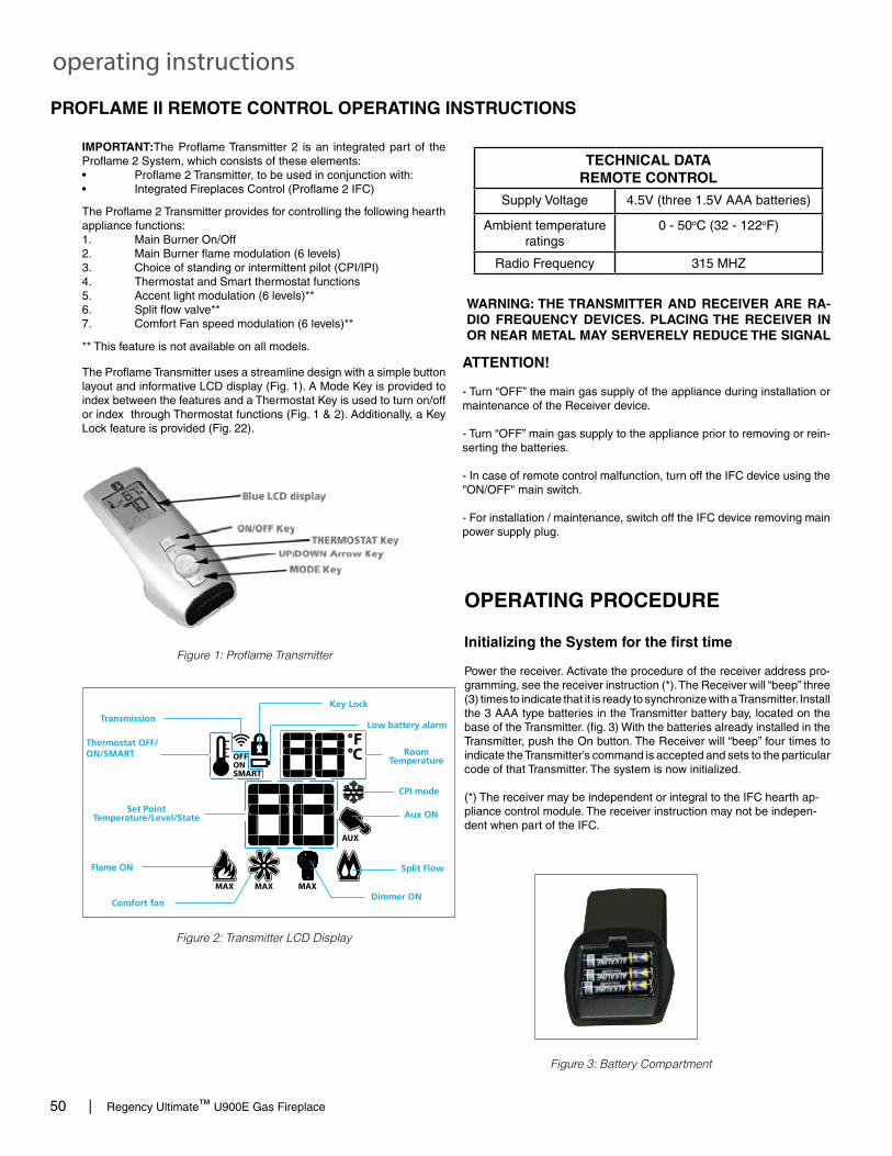
50 | Regency Ultimate™ U900E Gas Fireplace
operating instructions
PROFLAME II REMOTE CONTROL OPERATING INSTRUCTIONS
919-829 09.29.17
PROFLAME II REMOTE CONTROL OPERATING INSTRUCTIONS
WARNING: THE TRANSMITTER AND RECEIVER ARE RA‑DIO FREQUENCY DEVICES. PLACING THE RECEIVER IN OR NEAR METAL MAY SERVERELY REDUCE THE SIGNAL
The Proflame 2 Transmitter provides for controlling the following hearth appliance functions:1. Main Burner On/Off2. Main Burner flame modulation (6 levels)3. Choice of standing or intermittent pilot (CPI/IPI)4. Thermostat and Smart thermostat functions5. Accent light modulation (6 levels)**6. Split flow valve**7. Comfort Fan speed modulation (6 levels)**
** This feature is not available on all models.
IMPORTANT:The Proflame Transmitter 2 is an integrated part of the Proflame 2 System, which consists of these elements:• Proflame 2 Transmitter, to be used in conjunction with:• Integrated Fireplaces Control (Proflame 2 IFC)
The Proflame Transmitter uses a streamline design with a simple button layout and informative LCD display (Fig. 1). A Mode Key is provided to index between the features and a Thermostat Key is used to turn on/off or index through Thermostat functions (Fig. 1 & 2). Additionally, a Key Lock feature is provided (Fig. 22).
Figure 1: Proflame Transmitter
Figure 2: Transmitter LCD Display
TECHNICAL DATAREMOTE CONTROL
Supply Voltage 4.5V (three 1.5V AAA batteries)
Ambient temperature ratings
0 - 50oC (32 - 122oF)
Radio Frequency 315 MHZ
ATTENTION!
- Turn “OFF” the main gas supply of the appliance during installation or maintenance of the Receiver device.
- Turn “OFF” main gas supply to the appliance prior to removing or rein-serting the batteries.
- In case of remote control malfunction, turn off the IFC device using the "ON/OFF" main switch.
- For installation / maintenance, switch off the IFC device removing main power supply plug.
OPERATING PROCEDURE
Initializing the System for the first time
Power the receiver. Activate the procedure of the receiver address pro-gramming, see the receiver instruction (*). The Receiver will “beep” three (3) times to indicate that it is ready to synchronize with a Transmitter. Install the 3 AAA type batteries in the Transmitter battery bay, located on the base of the Transmitter. (fig. 3) With the batteries already installed in the Transmitter, push the On button. The Receiver will “beep” four times to indicate the Transmitter’s command is accepted and sets to the particular code of that Transmitter. The system is now initialized.
(*) The receiver may be independent or integral to the IFC hearth ap-pliance control module. The receiver instruction may not be indepen-dent when part of the IFC.
Figure 3: Battery Compartment
�
PRO
FLAM
E 2
TRAN
SMI
TTER
U
SE
ANDI
NST
AL L
The Proflame Remote Control System consists of three elements:
1. Proflame Transmitter.2. Proflame Receiver and a wiring harness to connect the Receiver to the gas valve, stepper motor and Fan Control Module.3. Proflame Fan Control Module (FCM)
The Proflame Transmitter uses a streamline design with a simple button layout and informative LCD display (Fig. 1). The Transmitter is powered by 3 AAA type batteries.A Mode Key is provided to Index between the features and a Thermostat Key is used to turn on/off or index through Thermostat functions (Fig. 1 & 2).
TRANsMITTER (Remote Control with LCD Display)
sysTEM DEsCRIpTIoN
Fig. 1: PROFLAME Transmitter.
Low battery alarmChild safety lock-out
RoomTemperature
Aux ON
Set PointTemperature/Level/State
Flame ON
Thermostat OFF/ON/SMART
Fan
Fig. 2: Transmitter LCD display.
Transmission
Turn on the Appliance
With the system OFF, press the ON/OFF Key on the Transmitter. The Transmitter display will show some other active Icons on the screen. At the same time the Receiver wil activate the appliance. A single “beep” from the Receiver will confirm reception of the command.
Turn off the Appliance
With the system ON, press the ON/OFF Key on the Transmitter. The Transmitter LCD display will only show the room temperature (Fig. 6). At the same time the Receiver will turn off the appliance. A single “beep” from the Receiver confirms reception of the command. Fig. 6: Remote Control display.
3 Positions Slider
Fig. 4: Proflame Receiver body.
PRG Key
Fig3: Battery compartment.
Fig. 4: Remote Control display in Farenheit. Fig. 5: Remote Control display in Celsius.
9957099_00_nero_mod_05-10-2011.i4 4 05/10/2011 8.36.38
1

Regency Ultimate™ U900E Gas Fireplace | 51
operating instructions
919-829 09.29.17
Figure 4: Remote Control dis-play in Farenheit.
Temperature indication Display
With the system in the "OFF" position, press the Thermostat Key and the Mode Key at the same time. Look at the LCD screen on the transmit-ter to verify that a C or F is visible to the right of the room temperature display (Figures 4 & 5).
Figure 5: Remote Control dis-play in Celsius.
Turn on the Appliance
With the system OFF, press the ON/OFF Key on the Transmitter. The Transmitter display will show some other active Icons on the screen. At the same time the Receiver wil ac-tivate the appliance. A single “beep” from the Receiver will confi rm recep-tion of the command.
Figure 6: Remote Control display
Remote-Flame Control
The profl ame has six (6) fl ame levels. With the system on, and the fl ame level at the maximum in the appliance, pressing the Down Arrow Key once will reduce the fl ame height by one step until the fl ame is turned off.The Up Arrow Key will increase the fl ame height each time it is pressed. If the Up Arrow Key is pressed while the system is on but the fl ame is off, the fl ame will come on in the high position. ( Fig. 7 & 8 ) A single “beep” will confi rm reception of the command.
Fig. 7
Fig. 8
Room Thermostat (Transmitter Operation)
The Remote Control can operate as a room thermostat. The thermostat can be set to a desired temperature to control the comfort level in a room.To activate this function, press the Thermostat Key (Fig. 1). The Lcd display on the Transmitter will change to show that the room thermostat is “ON” and the set temperature is now displayed (Fig. 9). To adjust the set temperature, press the Up or Down Arrow Keys until the desired set temperature is displayed on the LCD screen of the Transmitter.
Figure 9 Figure 10
Turn off the Appliance
With the system ON, press the ON/OFF Key on the Transmitter. The Transmitter LCD display will only show the room temperature (Fig. 6). At the same time the Receiver will turn off the appliance. A single “beep” from the Receiver confi rms reception of the command.
2

52 | Regency Ultimate™ U900E Gas Fireplace
operating instructions
919-829 09.29.17
Smart Thermostat (Transmitter Operation)
The Smart Thermostat function adjusts the fl ame height in accordance to the differencebetween the set point temperature and the actual room temperatures. As the roomtemperature gets closer to the set point the Smart Function will modulate the fl ame down.To activate this function, press the Thermostat Key (Fig. 1) until the word "SMART" appears tothe right of the temperature bulb graphic (Fig. 11).To adjust the set temperature, press the Up or Down Arrow Keys until the desidered settemperature is displayed on the LCD screen of the Transmitter (Fig. 12).Note. When Smart Thermostat is activated, manual fl ame height adjust-ment is disabled.
Figure 12Figure 11: Smart Flame Function
Fan Speed Control**
If the appliance is equipped with a hot air circulating fan, the speed of the fan can be controlled by the Profl ame system. The fan speed can be adjusted through six (6) speeds. To activate this function use the Mode Key (fi g.1) to index to the fan control icon (Fig. 13). Use the Up/Down Arrow Keys (fi g.1) to turn on, off or adjust the fan speed (fi g. 14). A single “beep”will confi rm reception of the command.
Figure 13 Figure 14
Remote dimmer control (Light)**
The auxiliary function controls the AUX power outlet by the dimmable light control. To activate this function use the Mode Key (fi g. 1) to index to the AUX icon (fi g. 15 & 16).The intensity of the output can be adjusted through six (6) levels. Use the Up/Down Arrow Keys (fi g.1) adjust the output level (fi g. 16). A single “beep” will confi rm reception of the command.
Note: This function is available only with the IFC Control Module.
Figure 15 Figure 16
Split Flow control**
The secondary burner is controlled by the split Flow. To activate this function use the Mode Key (fi g. 1) to index to the SPLIT FLOW mode icon (fi g. 17 & 18).Pressing the Up Arrow Key will activate the secondary burner. Pressing the Down Arrow Key will turn the secondary burner off. A single “beep” will confi rm the reception of the command.
Figure 17 Figure 18
3

Regency Ultimate™ U900E Gas Fireplace | 53
operating instructions
919-829 09.29.17
Smart Thermostat (Transmitter Operation)
The Smart Thermostat function adjusts the fl ame height in accordance to the differencebetween the set point temperature and the actual room temperatures. As the roomtemperature gets closer to the set point the Smart Function will modulate the fl ame down.To activate this function, press the Thermostat Key (Fig. 1) until the word "SMART" appears tothe right of the temperature bulb graphic (Fig. 11).To adjust the set temperature, press the Up or Down Arrow Keys until the desidered settemperature is displayed on the LCD screen of the Transmitter (Fig. 12).Note. When Smart Thermostat is activated, manual fl ame height adjust-ment is disabled.
Figure 12Figure 11: Smart Flame Function
Fan Speed Control**
If the appliance is equipped with a hot air circulating fan, the speed of the fan can be controlled by the Profl ame system. The fan speed can be adjusted through six (6) speeds. To activate this function use the Mode Key (fi g.1) to index to the fan control icon (Fig. 13). Use the Up/Down Arrow Keys (fi g.1) to turn on, off or adjust the fan speed (fi g. 14). A single “beep”will confi rm reception of the command.
Figure 13 Figure 14
Remote dimmer control (Light)**
The auxiliary function controls the AUX power outlet by the dimmable light control. To activate this function use the Mode Key (fi g. 1) to index to the AUX icon (fi g. 15 & 16).The intensity of the output can be adjusted through six (6) levels. Use the Up/Down Arrow Keys (fi g.1) adjust the output level (fi g. 16). A single “beep” will confi rm reception of the command.
Note: This function is available only with the IFC Control Module.
Figure 15 Figure 16
Split Flow control**
The secondary burner is controlled by the split Flow. To activate this function use the Mode Key (fi g. 1) to index to the SPLIT FLOW mode icon (fi g. 17 & 18).Pressing the Up Arrow Key will activate the secondary burner. Pressing the Down Arrow Key will turn the secondary burner off. A single “beep” will confi rm the reception of the command.
Figure 17 Figure 18
3

54 | Regency Ultimate™ U900E Gas Fireplace
maintenance
Top View of pilot flame
MAINTENANCE INSTRUCTIONS
1) Always turn off the valve before cleaning. For relighting, refer to lighting instructions. Keep the burner and control compartment clean by brushing and vacuuming at least once a year. When cleaning the logs, use a soft clean paint brush as the logs are fragile and easily dam-aged.
CAUTION: ANY SAFETY SCREEN OR GUARD REMOVED FOR SER-VICING AN APPLIANCE MUST BE REPLACED PRIOR TO OPERATING THE APPLIANCE.
Top View of pilot flame
Incorrect flame pattern will have small, probably yellow flames, not coming into proper contact with the rear of the burner.
NORMAL OPERATING SOUNDS OF GAS APPLIANCES
It is possible that you will hear some sounds from your gas appliance. This is perfectly normal due to the fact that there are various gauges and types of steel used within your appliance. Listed below are some examples. All are normal operating sounds and should not be considered as defects in your appliance.
Blower: Regency® gas appliances use high tech blowers to push heated air farther into the room. It is not unusual for the fan to make a "whirring" sound when ON. This sound will increase or decrease in volume depending on the speed setting of your fan speed control.
Burner Tray: The burner tray is positioned directly under the burner tube(s) and logs and is made of a differ-ent gauge material from the rest of the firebox and body. Therefore, the varying thicknesses of steel will expand and contract at slightly different rates which can cause "ticking" and "cracking" sounds. You should also be aware that as there are temperature changes within the unit these sounds will likely re-occur. Again, this is normal for steel fireboxes.
Pilot Flame: While the pilot flame is on it can make a very slight "whisper" sound.
Gas Control Valve: As the gas control valve turns ON and OFF, a dull clicking sound may be audible, this is normal operation of a gas regulator or valve.
Unit Body/Firebox: Different types and thicknesses of steel will expand and contract at different rates resulting in some "cracking" and "ticking" sounds will be heard throughout the cycling process.
WARNING: CHILDREN AND ADULTS SHOULD BE ALERTED TO THE HAZARDS OF HIGH SURFACE TEMPERATURE AND SHOULD STAY AWAY TO AVOID BURNS OR CLOTH-ING IGNITION. YOUNG CHILDREN SHOULD BE CAREFULLY SUPER-VISED WHEN THEY ARE IN THE SAME ROOM AS THE APPLIANCE.
8) Each time the appliance is lit, it may cause condensation and fog the glass. This conden-sation and fog is normal and will disappear in a few minutes as the glass heats up.
Never operate the appliance without the glass properly secured in place.
9) Periodically check the pilot flames. Correct flame pattern has three strong blue flames: 1 flowing around the thermopile and 1 around the thermocouple, and 1 flowing across the rear of the burner (it does not have to be touching the burner).
Note: If you have an incorrect flame pattern, contact your Regency® dealer for further instructions.
2) Clean glass (never when unit is hot), appliance, and door with a damp cloth. Never use an abrasive cleaner.
3) The heater is finished in a porcelain finish or with a heat resistant paint and should only be refinished with heat resistant paint (not with wall paint).
Never use an abrasive cleaner on the porcelain finish as it may scratch the surface.
4) Make a periodic check of burner for proper posi-tion and condition. Visually check the flame of the burner periodically, making sure the flames are steady; not lifting or floating. If there is a problem, call a qualified service person.
5) Caution: Label all wires prior to discon-nection when servicing controls. Wiring errors can cause improper and dangerous operation.
6) The appliance and venting system must be inspected before use, and at least annually, by a qualified field service person, to ensure that the flow of combustion and ventilation air is not obstructed.
During the annual service call, the burner should be removed from the burner tray and cleaned. Replace the embers but do not block the pilot.
7) Keep the area near the appliance clear and free from combustible materials, gasoline, and other flammable vapours and liquids.
DO NOT USE THIS APPLIANCE IF ANY PART HAS BEEN UNDER WA-TER. IMMEDIATELY CALL A QUALI-FIED SERVICE TECHNICIAN TO INSPECT THE APPLIANCE AND TO REPLACE ANY PART OF CONTROL SYSTEM AND ANY GAS CONTROL WHICH HAS BEEN UNDER WATER.
CLOTHING OR OTHER FLAM-MABLE MATERIAL SHOULD NOT BE PLACED ON OR NEAR THE APPLIANCE.
10) Verify operation after servicing.

Regency Ultimate™ U900E Gas Fireplace | 55
maintenanceGLASS GASKET If the glass gasket requires replacement use a tadpole glass gasket (Part # 936-157.
CAUTION: Wear gloves when removing damaged or broken glass.
WARNING: Do not operate the appliance with the glass panels removed, cracked or broken. Replacement of the glass panels should be done by a licensed or qualified service person.
GLASS DOOR
Your Regency® fireplace is supplied with high temperature 5mm-Ceramic glass. If your glass requires cleaning, we recommend using an approved glass cleaner available at all authorized dealers. Do not use abrasive materials.
CAUTION & WARNINGS:
* Do not clean when the glass is hot.* The use of substitute glass will void all product
warranties.* Care must be taken to avoid breakage of the
glass.* Do not strike or abuse the glass.* Do not operate this fireplace without the glass
front or with a cracked or broken glass front.* Wear gloves when removing damaged or broken
glass.* Replacement of the glass panel(s) should be
done by a licensed or qualified service person.
GLASS REPLACEMENT
In the event that you break your glass by impact, purchase your replacement from an authorized Regency® dealer only.
Replacement neo-ceramic glass (Part # 940-373/P) is shipped with gasket.
GENERAL VENT MAINTENANCE
Conduct an inspection of the venting system semi-annually. Recommended areas to inspect as follows:
1. Check the Venting System for corrosion in areas that are exposed to the elements. These will appear as rust spots or streaks, and in extreme cases, holes. These components should be replaced immediately.
2. Remove the Cap, and shine a flashlight down the Vent. Remove any bird nests, or other foreign material.
3. Check for evidences of excessive condensation, such as water droplets forming in the inner liner, and subsequently dripping out the joints, Continuous condensation can cause corrosion of caps, pipe, and fittings. It may be caused by having excessive lateral runs, too many elbows, and exterior portions of the system being exposed to cold weather.
4. Inspect joints, to verify that no pipe sections or fittings have been disturbed, and consequently loosened. Also check mechanical supports such as Wall Straps, or plumbers' tape for rigidity.
5. Remove the inner panels - reverse of "Inner panel Installation" in this manual.
6. Remove the burner tray cover by lifting up and out as shown below.

56 | Regency Ultimate™ U900E Gas Fireplace
maintenance
FAN SERVICE
PRIOR TO SERVICING THE FAN, ENSURE UNIT HAS COOLED TO ROOM TEMPERATURE, ALL POWER IS DISCONNECTED AND GAS SUPPLY IS TURNED OFF.
1. Remove faceplate, inner frame, glass door, front trim piece and inner panels - see instructions in this manual.
2. Remove logs.
3. Remove burner side panels by lifting out as shown in Diagram 1.
9. Remove two (2) screws to remove fan shown in Diagram 6.
10. Reverse steps to reinstall fan.
8. Remove access panel by removing eight(8) screws in locations shown in Diagram 4.
Diagram 5 - Fan Screws
Diagram 4 - Access Tray screws
Diagram 1 - Burner Side Panels
4. Remove enamel side panels by loosening the 2 screws (1 per side) in locations noted and remove the 2 clips.
5. Remove front lip by removing 2 screws located on firebox floor.
6. Remove rear log tray by removing 3 screws as shown in Diagram 2 below.
Diagram 2 - Side Panel, Front Lip & Log Tray Screw Locations
Side Panel Screws
Log Tray Screws
Front Lip Screws
Diagram 3 - Burner Screw Locations
7. Remove burner by removing 2 screws in locations shown below.

Regency Ultimate™ U900E Gas Fireplace | 57
maintenance
GLASS DOOR REMOVAL
2. Pull forward until the lower door latch is disengaged from the door frame.
3. Push downward until the Lower Door Latch is below the Door Frame.
4. Release the lower door latch until it reaches its resting point.
5. Remove the door tool and repeat steps 1-5 on the other lower door latch.
6. Pull the bottom of the door towards you until the door is angled away from the firebox by about 30°. Lift the door up and over the upper door hooks.
7. To install the glass door - reverse steps.
1. Insert the door tool into the lower door latch.
WARNING: Do not operate the appliance with the glass panels removed, cracked or broken. Replacement of the glass panels should be done by a licensed or qualified service person. Glass should be cool if cleaning is necessary.
Door Tool
Upper Door Hooks
Lower Door Latches

58 | Regency Ultimate™ U900E Gas Fireplace
maintenance
VALVE TRAY REPLACEMENT
PRIOR TO VALVE TRAY REPLACEMENT, ENSURE UNIT HAS COOLED TO ROOM TEMPERATURE, ALL POWER IS DISCONNECTED AND GAS SUPPLY IS TURNED OFF.
8. Remove valve tray by removing 14 screws in locations shown below.
9. Lift out valve tray.
10. Replace valve tray and reverse steps.
Diagram 4 - Valve Tray Screw Locations
Diagram 5 - Valve Tray Removal
1. Remove faceplate, inner frame, glass door, front trim piece and inner panels - see instructions in this manual.
2. Remove logs.
3. Remove burner side panels by lifting out as shown in Diagram 1.
Diagram 1 - Burner Side Panels
4. Remove enamel side panels by loosening the 2 screws (1 per side) in locations noted and remove the 2 clips.
5. Remove front lip by removing 2 screws located on firebox floor.
6. Remove rear log tray by removing 3 screws as shown in Diagram 2 below.
Diagram 2 - Side Panel, Front Lip & Log Tray Screw Locations
Diagram 3 - Burner Screw Locations
Side Panel Screws
Log Tray Screws
Front Lip Screws
7. Remove burner by removing 2 screws in locations shown below.
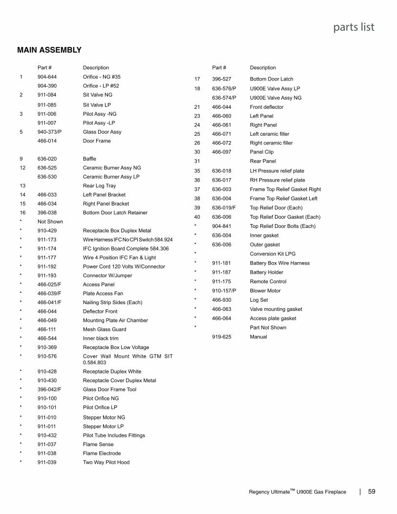
Regency Ultimate™ U900E Gas Fireplace | 59
parts list
MAIN ASSEMBLY
Part # Description
1 904-644 Orifice - NG #35
904-390 Orifice - LP #52
2 911-084 Sit Valve NG
911-085 Sit Valve LP
3 911-006 Pilot Assy -NG
911-007 Pilot Assy -LP
5 940-373/P Glass Door Assy
466-014 Door Frame
9 636-020 Baffle
12 636-525 Ceramic Burner Assy NG
636-530 Ceramic Burner Assy LP
13 Rear Log Tray
14 466-033 Left Panel Bracket
15 466-034 Right Panel Bracket
16 396-038 Bottom Door Latch Retainer
* Not Shown
* 910-429 Receptacle Box Duplex Metal
* 911-173 Wire Harness IFC No CPI Switch 584.924
* 911-174 IFC Ignition Board Complete 584.306
* 911-177 Wire 4 Position IFC Fan & Light
* 911-192 Power Cord 120 Volts W/Connector
* 911-193 Connector W/Jumper
* 466-025/F Access Panel
* 466-039/F Plate Access Fan
* 466-041/F Nailing Strip Sides (Each)
* 466-044 Deflector Front
* 466-049 Mounting Plate Air Chamber
* 466-111 Mesh Glass Guard
* 466-544 Inner black trim
* 910-369 Receptacle Box Low Voltage
* 910-576 Cover Wall Mount White GTM SIT 0.584.803
* 910-428 Receptacle Duplex White
* 910-430 Receptacle Cover Duplex Metal
* 396-042/F Glass Door Frame Tool
* 910-100 Pilot Orifice NG
* 910-101 Pilot Orifice LP
* 911-010 Stepper Motor NG
* 911-011 Stepper Motor LP
* 910-432 Pilot Tube Includes Fittings
* 911-037 Flame Sense
* 911-038 Flame Electrode
* 911-039 Two Way Pilot Hood
Part # Description
17 396-527 Bottom Door Latch
18 636-576/P U900E Valve Assy LP
636-574/P U900E Valve Assy NG
21 466-044 Front deflector
23 466-060 Left Panel
24 466-061 Right Panel
25 466-071 Left ceramic filler
26 466-072 Right ceramic filler
30 466-097 Panel Clip
31 Rear Panel
35 636-018 LH Pressure relief plate
36 636-017 RH Pressure relief plate
37 636-003 Frame Top Relief Gasket Right
38 636-004 Frame Top Relief Gasket Left
39 636-019/F Top Relief Door (Each)
40 636-006 Top Relief Door Gasket (Each)
* 904-841 Top Relief Door Bolts (Each)
* 636-004 Inner gasket
* 636-006 Outer gasket
* Conversion Kit LPG
* 911-181 Battery Box Wire Harness
* 911-187 Battery Holder
* 911-175 Remote Control
* 910-157/P Blower Motor
* 466-930 Log Set
* 466-063 Valve mounting gasket
* 466-064 Access plate gasket
* Part Not Shown
919-625 Manual

60 | Regency Ultimate™ U900E Gas Fireplace
parts list
MAIN ASSEMBLY

Regency Ultimate™ U900E Gas Fireplace | 61
parts list
ACCESSORIES
32
33
Part # Description
32 636-914 Inner door frame - Black w/ Screen33 636-924 Faceplate & Door Frame Black 636-951 Faceplate & Door Frame Black Glass (not shown) 467-900 Steel Stud Framing (not shown) 636-936 Non-combustible board (not shown) 636-969 LP conversion kit (not shown)

62 | Regency Ultimate™ U900E Gas Fireplace
warranty
Limited Lifetime Warranty FPI Fireplace Products International Ltd. (for Canadian customers) and Fireplace Products U.S., Inc. (for U.S. customers) (collectively referred to herein as “FPI”) extends this Limited Lifetime Warranty to the original purchaser of this appliance provided the product remains in the original place of installation. The items covered by this limited warranty and the period of such coverage is set forth in the table below. Some conditions apply (see below). The policy is not transferable, amendable or negotiable under any circumstances.
Indoor Gas Products Part Supplier Labor
Coverage Warranty Coverage Parts and Labor Lifetime 5 years 2 years 1 year Warranty (Years)
Firebox and Heat Exchanger 3 Steel Burner Tube 3 Glass Thermal breakage only 3 All Surrounds/Inlays Finishes 3 Brick Panels/Log sets/Ceramic Burners 3
All Castings 3 Valve assembly and all gas control components, (Pilot assembly, flame sensors, Spark Electrode, Pilot Tubing, Orifices, Thermocouple, Thermopile)
2
All Other Electrical components,(Ignition Control Boards, Wiring, Switches, Blowers, Blower Control Module, Battery Pack, Remote Control Systems)
2
Enamel Panels 1 Venting/Venting Components 1 All Stainless steel surrounds 1 All Firebox Media (Crystals, Firebeads, Volcanic, Ceramic & Spa Stones)
1
All hardware 1 Mesh/Glass Safety Barriers 1 Accent Light Bulbs 1 Glass (Crazing) 1
Conditions: Warranty protects against defect in manufacture or FPI factory assembled components only, unless herein specified otherwise. Any part(s) found to be defective during the warranty period as outlined above will be repaired or replaced at FPI’s option through an accredited distributor, dealer or pre-approved and assigned agent provided that the defective part is returned to the distributor, dealer or agent for inspection if requested by FPI. Alternatively, FPI may at its own discretion fully discharge all of its obligations under the warranty by refunding the verified purchase price of the product to the original purchaser. The purchase price must be confirmed by the original Bill of Sale. The authorized selling dealer, or an alternative authorized FPI dealer if pre-approved by FPI, is responsible for all in-field diagnosis and service work related to all warranty claims. FPI is not responsible for results or costs of workmanship of unauthorized FPI dealers or agents in the negligence of their service work.
Revision Date: December 2016 Regency Gas Products Warranty

Regency Ultimate™ U900E Gas Fireplace | 63
warranty
At all times FPI reserves the right to inspect reported complaints on location in the field claimed to be defective prior to processing or authorizing of any claim. Failure to allow this upon request will void the warranty. All warranty claims must be submitted by the dealer servicing the claim, including a copy of the Bill of Sale (proof of purchase by you). All claims must be complete and provide full details as requested by FPI to receive consideration for evaluation. Incomplete claims may be rejected. Unit must be installed according to all manufacturers’ instructions as per the manual. All Local and National required codes must be met. The installer is responsible to ensure the unit is operating as designed at the time of installation. The original purchaser is responsible for annual maintenance of the unit, as outlined in the owner’s manual. As outlined below, the warranty may be voided due to problems caused by lack of maintenance. Repair/replacement parts purchased by the consumer from FPI after the original coverage has expired on the unit will carry a 90 day warranty, valid with a receipt only. Any item shown to be defective will be repaired or replaced at our discretion. No labor coverage is included with these parts Exclusions: This Limited Lifetime Warranty does not extend to paint, rust or corrosion of any kind due to a lack of maintenance or improper venting, combustion air provision, corrosive chemicals (i.e. chlorine, salt, air, etc.), door or glass gasketing. Malfunction, damage or performance based issues as a result of environmental conditions, location, chemical damages, downdrafts, installation error, installation by an unqualified installer, incorrect chimney components (including but not limited to cap size or type), operator error, abuse, misuse, use of improper fuels , lack of regular maintenance and upkeep, acts of God, weather related problems from hurricanes, tornados, earthquakes, floods, lightning strikes/bolts or acts of terrorism or war, which result in malfunction of the appliance are not covered under the terms of this Limited Lifetime Warranty. FPI has no obligation to enhance or modify any unit once manufactured (i.e. as products evolve, field modifications or upgrades will not be performed on existing appliances). This warranty does not cover dealer travel costs for diagnostic or service work. All labor rates paid to authorized dealers are subsidized, pre-determined rates. Dealers may charge homeowner for travel and additional time beyond their subsidy. Any unit showing signs of neglect or misuse will not be covered under the terms of this warranty policy and may void this warranty. This includes units with rusted or corroded fireboxes which have not been reported as rusted or corroded within three (3) months of installation/purchase. Units which show evidence of being operated while damaged, or with problems known to the purchaser and causing further damages will void this warranty. Units where the serial no. has been altered, deleted, removed or made illegible will void this warranty. Minor movement, expansion and contraction of the steel is normal and is not covered under the terms of this warranty. Freight damages for products or parts are not covered under the terms of the warranty. Products made or provided by other manufacturers and used in conjunction with the FPI appliance without prior authorization from FPI may void this warranty.
Revision Date: December 2016 Regency Gas Products Warranty

64 | Regency Ultimate™ U900E Gas Fireplace
warranty
Limitations of Liability: The original purchaser’s exclusive remedy under this warranty, and FPI’s sole obligation under this warranty, express or implied, in contract or in tort, shall be limited to replacement, repair, or refund, as outlined above. IN NO EVENT WILL FPI BE LIABLE UNDER THIS WARRANTY FOR ANY INCIDENTAL OR CONSEQUENTIAL COMMERCIAL DAMAGES OR DAMAGES TO PROPERTY. TO THE EXTENT PERMITTED BY APPLICABLE LAW, FPI MAKES NO EXPRESS WARRANTIES OTHER THAN THE WARRANTY SPECIFIED HEREIN. THE DURATION OF ANY IMPLIED WARRANTY IS LIMITED TO DURATION OF THE EXPRESSED WARRANTY SPECIFIED ABOVE. IF IMPLIED WARRANTIES CANNOT BE DISCLAIMED, THEN SUCH WARRANTIES ARE LIMITED IN DURATION TO THE DURATION OF THIS WARRANTY. Some U.S. states do not allow limitations on how long an implied warranty lasts, or allow exclusion or limitation of incidental or consequential damages, so the above limitations or exclusions may not apply to you. Customers located outside the U.S. should consult their local, provincial or national legal codes for additional terms which may be applicable to this warranty. How to Obtain Warranty Service: Customers should contact the authorized selling dealer to obtain warranty service. In the event the authorized selling dealer is unable to provide warranty service, please contact FPI by mail at the address listed below. Please include a brief description of the problem and your address, email and telephone contact information. A representative will contact you to make arrangements for an inspection and/or warranty service. Canadian Warrantor: FPI Fireplace Products International Ltd. 6988 Venture St. Delta, British Columbia Canada, V4G 1H4
U.S. Warrantor: Fireplace Products U.S., Inc. PO Box 2189 PMB 125 Blaine, WA United States, 98231
Or contact the Regency Customer Care Centre at 1-800-442-7432 (phone) / 604-946-4349 (fax) Product Registration and Customer Support: Thank you for choosing a Regency Fireplace. Regency strives to be a world leader in the design, manufacture, and marketing of hearth products. To provide the best support for your product, we request that you complete a product registration form at http://www.regency-fire.com/Customer-Care/Warranty-Registration.aspx within ninety (90) days of purchase.
Revision Date: December 2016 Regency Gas Products Warranty

Regency Ultimate™ U900E Gas Fireplace | 65
warranty
Product Registration and Customer Support:
Thank you for choosing a Regency Fireplace. Regency strives to be a world leader in the design, manufacture, and marketing of hearth products. To provide the best support for your product, we request that you complete a product registration form found on our Web Site under Customer Care within ninety (90) days of purchase.
For purchases made in CANADA or the UNITED STATES: http://www.regency-fire.com/Customer-Care/Warranty-Registration.aspx
For purchases made in AUSTRALIA: http://www.regency-fire.com.au/Customer-Care/Warranty-Registration.aspx
You may also complete the warranty registration form below to register your Regency Fireplace Product and mail and/or fax it back to us, and we will register the warranty for you. It is important you provide us with all the information below in order for us to serve you better.
Warranty Registration Form (or Register online immediately at the above Web Site):
Warranty Details
Serial Number (required):
Purchase Date (required) (mm/dd/yyyy):
Product Details
Product Model (required):
Dealer Details
Dealer Name (required):
Dealer Address:
Dealer Phone #:
Installer:
Date Installed (mm/dd/yyyy):
Your Contact Details (required)
Name:
Address:
Phone:
Email:
For purchases made in CANADA:
FPI Fireplace Products International Ltd. 6988 Venture St. Delta, British Columbia Canada, V4G 1H4
For purchases made in the UNITED STATES:
Fireplace Products U.S., Inc. PO Box 2189 PMB 125 Blaine, WA United States, 98231
Phone: 604-946-5155 Fax: 604-946-4349
Phone: 604-946-5155 Fax: 604-946-4349
For purchases made in AUSTRALIA:
Fireplace Products Australia Pty Ltd 1- 3 Conquest Way Hallam, VIC Australia, 3803
Phone: +61 3 9799 7277 Fax: +61 3 9799 7822
For fireplace care and tips and answers to most common questions please visit our Customer Care section on our Web Site. Please feel free to contact your selling dealer if you have any questions about your Regency product.


Printed in CanadaRegency and Ultimate are trademarks of FPI Fireplace Products International Ltd.© Copyright 2018, FPI Fireplace Products International Ltd. All rights reserved.
Installer: Please complete the following information
Dealer Name & Address: ______________________________________________
___________________________________________________________________
Installer: ___________________________________________________________
Phone #: ___________________________________________________________
Date Installed: ______________________________________________________
Serial No.: __________________________________________________________