Embed Size (px)
Citation preview

CAUTIONBEFORE SERVICING THE UNIT,READ THE SAFETY PRECAUTIONS IN THIS MANUAL.
MODEL : LFX28978**
COLOR : STAINLESS(ST)WESTERN BLACK(SB)SUPER WHITE(SW)
REFRIGERATOR SERVICE MANUAL
- 2 -
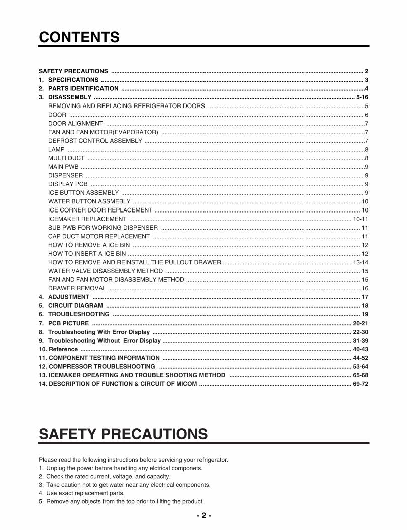
CONTENTS
SAFETY PRECAUTIONS ....................................................................................................................................................... 21. SPECIFICATIONS ............................................................................................................................................................. 32. PARTS IDENTIFICATION ..................................................................................................................................................43. DISASSEMBLY ............................................................................................................................................................ 5-16
REMOVING AND REPLACING REFRIGERATOR DOORS ..............................................................................................5DOOR ................................................................................................................................................................................ 6DOOR ALIGNMENT ...........................................................................................................................................................7FAN AND FAN MOTOR(EVAPORATOR) ..........................................................................................................................7DEFROST CONTROL ASSEMBLY ....................................................................................................................................7LAMP ..................................................................................................................................................................................8MULTI DUCT ......................................................................................................................................................................8MAIN PWB ..........................................................................................................................................................................9DISPENSER ...................................................................................................................................................................... 9DISPLAY PCB ................................................................................................................................................................... 9ICE BUTTON ASSEMBLY ................................................................................................................................................. 9WATER BUTTON ASSMEBLY ........................................................................................................................................ 10ICE CORNER DOOR REPLACEMENT ........................................................................................................................... 10ICEMAKER REPLACEMENT ..................................................................................................................................... 10-11SUB PWB FOR WORKING DISPENSER ....................................................................................................................... 11CAP DUCT MOTOR REPLACEMENT ............................................................................................................................ 11HOW TO REMOVE A ICE BIN ........................................................................................................................................ 12HOW TO INSERT A ICE BIN ........................................................................................................................................... 12HOW TO REMOVE AND REINSTALL THE PULLOUT DRAWER ............................................................................. 13-14WATER VALVE DISASSEMBLY METHOD .................................................................................................................... 15FAN AND FAN MOTOR DISASSEMBLY METHOD ........................................................................................................ 15DRAWER REMOVAL ...................................................................................................................................................... 16
4. ADJUSTMENT ................................................................................................................................................................ 175. CIRCUIT DIAGRAM ........................................................................................................................................................ 186. TROUBLESHOOTING .................................................................................................................................................... 197. PCB PICTURE ........................................................................................................................................................... 20-218. Troubleshooting With Error Display ....................................................................................................................... 22-309. Troubleshooting Without Error Display ................................................................................................................. 31-3910. Reference .................................................................................................................................................................. 40-4311. COMPONENT TESTING INFORMATION ................................................................................................................. 44-5212. COMPRESSOR TROUBLESHOOTING ................................................................................................................... 53-6413. ICEMAKER OPEARTING AND TROUBLE SHOOTING METHOD ......................................................................... 65-6814. DESCRIPTION OF FUNCTION & CIRCUIT OF MICOM ........................................................................................... 69-72
SAFETY PRECAUTIONS
Please read the following instructions before servicing your refrigerator.1. Unplug the power before handling any elctrical componets.2. Check the rated current, voltage, and capacity.3. Take caution not to get water near any electrical components.4. Use exact replacement parts.5. Remove any objects from the top prior to tilting the product.

- 3 -
1. SPECIFICATIONS
1-1 LFX28978**
DOOR DESIGN
DIMENSIONS (inches)
NET WEIGHT (pounds)
COOLING SYSTEM
TEMPERATURE CONTROL
DEFROSTING SYSTEM
DOOR FINISH
HANDLE TYPE
INNER CASE
INSULATION
ITEMS
Side Rounded
35 3/4 X 35 3/8 X 69 3/4 (WXDXH) 28cu.ft.
155kg (342lb)
Fan Cooling
Micom Control
Full Automatic
Heater Defrost
PCM, VCM, Stainless
Bar
ABS Resin
Polyurethane Foam
SPECIFICATIONS
28 cu.ft.
VEGETABLE TRAY
COMPRESSOR
EVAPORATOR
CONDENSER
REFRIGERANT
LUBRICATING OIL
DEFROSTING DEVICE
ITEMS
Clear Drawer Type
Linear
Fin Tube Type
Spiral Condenser
R-134a (140 g)
ISO10 (280 ml)
SHEATH HEATER
LED Module(24)
Bulb Lamp
SPECIFICATIONS
LAMPREFRIGERATOR
FREEZER
DIMENSIONS
Depth w/ Handles
Depth w/o Handles
Depth w/o Door
Depth (Total with Door Open)
Height to Top of Case
Height to Top of Door Hinge
Width
Width (door open 90 deg. w/o handle)
Width (door open 90 deg. w/ handle)
A
B
C
D
E
F
G
H
I
35 3/8 in
32 7/8 in
29 in
47 5/8 in
68 3/8 in
69 3/4 in
35 3/4 in
39 1/4 in
44 1/4 in
Description LFX28978**
- 4 -
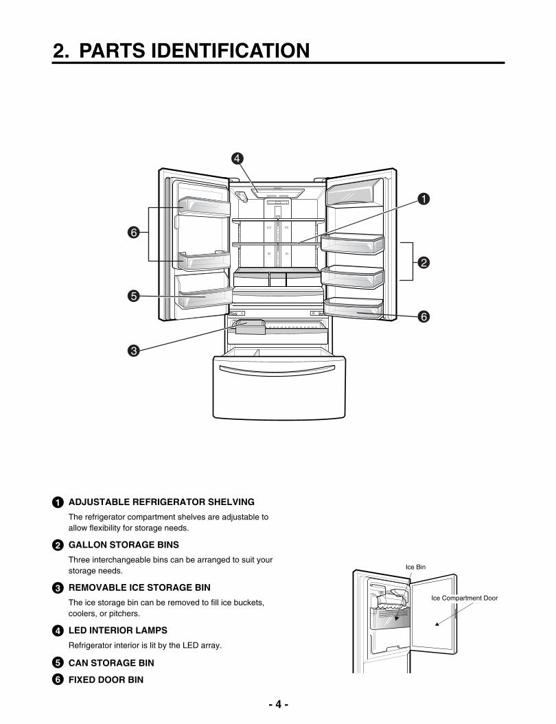
2. PARTS IDENTIFICATION
3
5
6
6
1
2
4
ADJUSTABLE REFRIGERATOR SHELVING1
The refrigerator compartment shelves are adjustable toallow flexibility for storage needs.
GALLON STORAGE BINS2
Three interchangeable bins can be arranged to suit yourstorage needs.
REMOVABLE ICE STORAGE BIN3
The ice storage bin can be removed to fill ice buckets,coolers, or pitchers.
LED INTERIOR LAMPS4
Refrigerator interior is lit by the LED array.
CAN STORAGE BIN5
FIXED DOOR BIN6

- 5 -
3. DISASSEMBLY
3-1 REMOVING AND REPLACING REFRIGERATOR DOORS
Removing Refrigerator Door
CAUTION: Before you begin, unplug the refrigerator. Remove food and bins from doors.
Left Door -FIG. 2
1. Disconnect water supply tube by pushing back on the disconnect ring (3).-FIG. 1 2. Open door. Loosen top hinge cover screw (1).
Use flat tip screwdriver to pry back hooks on front underside of cover (2). Lift up cover.3. Disconnect door switch wire harness and remove the cover.4. Pull out the tube.5. Disconnect all 3 wiring harnesses (4). Remove the grounding screw (5).6. Rotate hinge lever (6) counterclockwise. Lift top hinge (7) free of hinge lever latch (8).
7. Lift door from middle hinge pin and remove door.8. Place the door with the insides facing up, on a not scratch surface.
CAUTION: When lifting hinge free from the latch, be careful that door does not fall forward.
Right Door -FIG. 3
1. Open the door, remove 1 screw on the top of the hinge cover. Loosen top hinge cover screw (1). Lift up cover (2). 2. Disconnect door switch wire harness and remove the cover.3. Rotate hinge lever (3) clockwise. Lift top hinge (4) free of hinge lever latch (5).4. Lift door from middle hinge pin and remove door.
5. Place the door with the insides facing up, on a not scratch surface.
CAUTION: When lifting hinge free from the latch, be careful that the door does not fall forward.
Figure 2 Figure 3
Figure 1
1) Insert the tube until you can see only one ofthe lines printed on the tube.
2) After inserting, pull the tube to ascertain thatit is secure.
3) Assemble clip.

- 6 -
1. Remove gasketPull gasket free from gasket channel on the fourremaining sides of door.
3-2 DOOR
Mullion Removal
1. Remove 2 screws.
Door Gasket Removal
2. Lift Mullion up carefully.
3. Disconnect wire harness.
Door Gasket Replacement
1. Insert gasket into channelPress gasket into channels on the four remainingsides of door.
2. Insert mullion into the channel.Insert the cover assembly into bracket, door.
Mullion Replacement
1. Connect wire harness.
3. Assemble 2 screws.
Figure 1
Figure 2
Figure 3
Figure 4
Figure 5
Figure 6
Figure 7
Figure 8

- 7 -
* Ice Fan Scroll Assembly Replacement
1) Remove the plastic guide on the left side, using aphillips screwdriver to remove the screws.
2) Pull off the sensor cover.3) Remove the grill cover.4) Gently pull on the grill assembly to remove.5) Disconnect the wiring harness.6) Remove all screws on the scroll assembly.
(1) (2)
(3) (4)
(5) (6)
3-5 DEFROST CONTROL ASSEMBLY
Defrost Control assembly consists of Defrost Sensor andFUSE-M.The Defrost Sensor works to defrost automatically. It isattached to the metal side of the Evaporator and senses itstemperature. At 46F(8°C), it turns the Defrost Heater off.Fuse-M is a safety device for preventing over-heating ofthe Heater when defrosting.1. Pull out the grille assembly. (Figure 12)2. Separate the connector with the Defrost Control
assembly and replace the Defrost Control assembly aftercutting the Tie Wrap. (Figure 13)
Figure 12 Figure 13
GRILLE ASSEMBLY DEFROST-CONTROLASSEMBLY
3-3 Door Alignment
If the space between the door are uneven, follow the instructions to align them.Remove the Base Grillie. Turn the leveling legs counterclock wise to raise or clock wise to lower the height of thefront of the refrigerator by using flat blade screw driver or11/32" wrench. Use the wrench (Included with the UserManual) to adjust the bolt in the door hinge to adjust theheight. (CCW to raise or CW to lower the height.)
3-4 FAN AND FAN MOTOR(EVAPORATOR)
1. Remove the freezer drawer. (If your refrigerator has anicemaker, remove the icemaker first)
2. Remove the plastic guide for slides on left side byunscrewing phillips head screws.
3. Remove the grille by removing 4 screws and pulling thegrille forward.
4. Remove the Fan Motor assembly by loosening 3 screwsand disassembling the shroud.
5. Pull out the fan and separate the Fan Motor and Bracket.
FAN MOTOR
BRACKETMOTOR
Shroud
Figure 9
Figure 10
Figure 11

- 8 -
Figure 18
1. Unplug refrigerator power cord form outlet.2. Remove screw with driver.3. Grasp the cover Lamp, pull the cover downward.
3-6-2 Freezer Compartment Lamp
3-7 MULTI DUCT
1. Romove the upper andlower caps with a flatscrewdriver and remove2 screws.(Figure 19)
2. Disconnect the lead wireon the bottom position.
Figure 19
Figure 14
Figure 15
3-6 LAMP
Unplug, or disconnect power at the circuit breaker.If necessary, remove top shelf or shelves.
1) Release 2 screws.2) Hold both ends and pull down to remove.
3-6-1 Refrigerator Compartment Lamp
Figure 16
4) Use a flat tool as shown below to remove the lampcover.
Figure 17
5) To remove the LED assembly, pull apart the cover.
Cover, lamp
Case, lamp
LED, Assembly
3) To remove the lamp case and cover, release 2 screwsas shown.
- 9 -
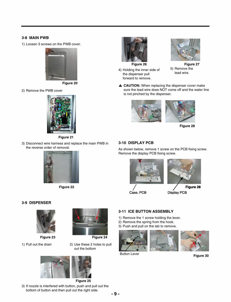
3-8 MAIN PWB
1) Loosen 3 screws on the PWB cover.
3-9 DISPENSER
1) Pull out the drain
2) Remove the PWB cover
3) Disconnect wire harness and replace the main PWB inthe reverse order of removal.
3-10 DISPLAY PCB
As shown below, remove 1 screw on the PCB fixing screw.Remove the display PCB fixing screw.
3-11 ICE BUTTON ASSEMBLY
1) Remove the 1 screw holding the lever.2) Remove the spring from the hook.3) Push and pull on the tab to remove.
CAUTION: When replacing the dispenser cover makesure the lead wire does NOT come off and the water lineis not pinched by the dispenser.
Case, PCB
Button Lever
Display PCB
Figure 20
Figure 21
Figure 22
Figure 23 Figure 24
Figure 25
Figure 30
Figure 28
Case, PCB Display PCB
Figure 29
Figure 28
2) Use these 2 holes to pullout the bottom
3) If nozzle is interfered with button, push and pull out thebottom of button and then pull out the right side.
4) Holding the inner side ofthe dispenser pullforward to remove.
5) Remove thelead wire.
Figure 26 Figure 27
- 10 -- 10 -
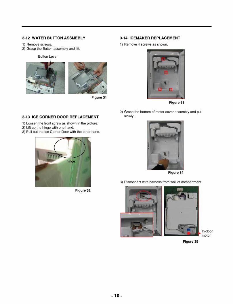
3-13 ICE CORNER DOOR REPLACEMENT
1) Loosen the front screw as shown in the picture.2) Lift up the hinge with one hand.3) Pull out the Ice Corner Door with the other hand.
3-12 WATER BUTTON ASSMEBLY
1) Remove screws.2) Grasp the Button assembly and lift.
Button Lever
hinge
3-14 ICEMAKER REPLACEMENT
1) Remove 4 screws as shown.
2) Grasp the bottom of motor cover assembly and pullslowly.
3) Disconnect wire harness from wall of compartment.
In-doormotor
Figure 31
Figure 32
Figure 35
Figure 33
Figure 34
- 11 -
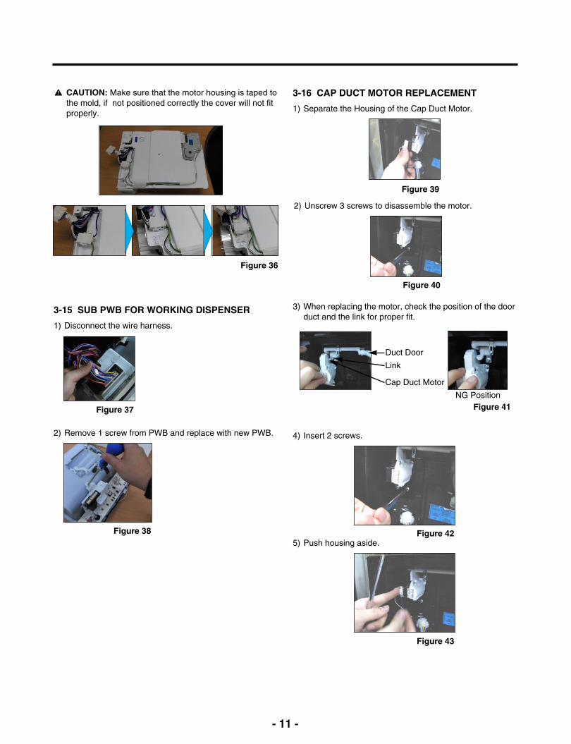
3-16 CAP DUCT MOTOR REPLACEMENT
1) Separate the Housing of the Cap Duct Motor.
3) When replacing the motor, check the position of the doorduct and the link for proper fit.
Link
Duct Door
Cap Duct Motor
NG Position
2) Unscrew 3 screws to disassemble the motor.
4) Insert 2 screws.
5) Push housing aside.
3-15 SUB PWB FOR WORKING DISPENSER
1) Disconnect the wire harness.
2) Remove 1 screw from PWB and replace with new PWB.
CAUTION: Make sure that the motor housing is taped tothe mold, if not positioned correctly the cover will not fitproperly.
Figure 36
Figure 37
Figure 38
Figure 43
Figure 42
Figure 41
Figure 40
Figure 39

- 12 -
3-17 HOW TO REMOVE A ICE BIN
1) Grip the handles, as shown.
2) Tilt and lift slightly as shown.
3-18 HOW TO INSERT A ICE BIN
1) Insert the Ice Bin, slightly tilting to avoid touching theIcemaker. (Especially, Ice-Detecting Sensor)
3) Remove ice bin slowly.
Figure 44
Figure 45
Figure 46
Figure 47
- 13 -
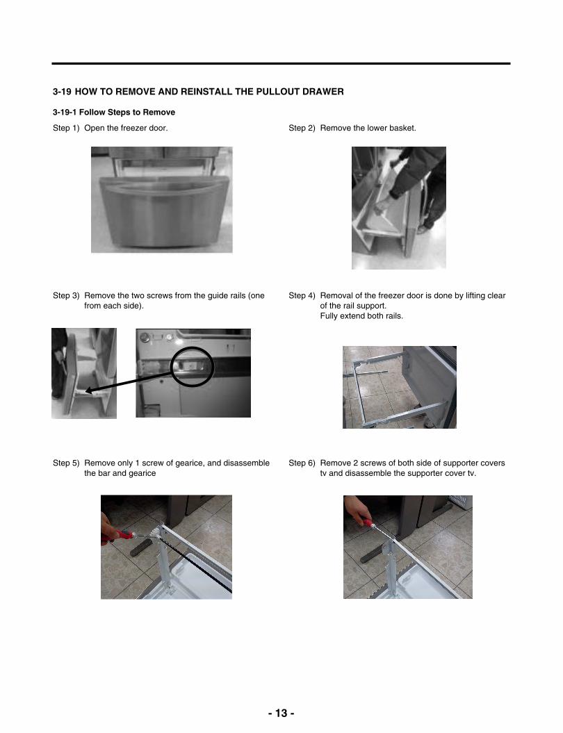
3-19 HOW TO REMOVE AND REINSTALL THE PULLOUT DRAWER
3-19-1 Follow Steps to Remove
Step 1) Open the freezer door.
Step 3) Remove the two screws from the guide rails (onefrom each side).
Step 2) Remove the lower basket.
Step 4) Removal of the freezer door is done by lifting clearof the rail support. Fully extend both rails.
Step 6) Remove 2 screws of both side of supporter coverstv and disassemble the supporter cover tv.
Step 5) Remove only 1 screw of gearice, and disassemblethe bar and gearice
- 14 -
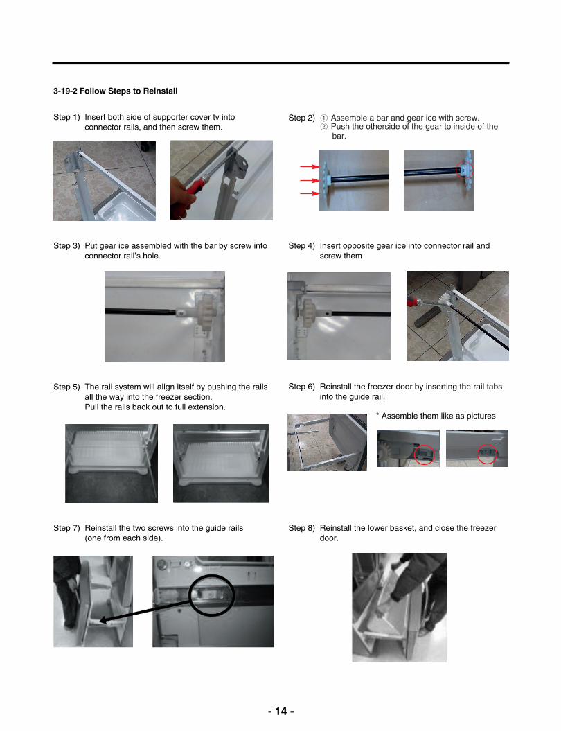
3-19-2 Follow Steps to Reinstall
Step 1) Insert both side of supporter cover tv intoconnector rails, and then screw them.
Step 3) Put gear ice assembled with the bar by screw intoconnector rail’s hole.
Step 4) Insert opposite gear ice into connector rail andscrew them
Step 6) Reinstall the freezer door by inserting the rail tabsinto the guide rail.
Step 8) Reinstall the lower basket, and close the freezerdoor.
Step 5) The rail system will align itself by pushing the railsall the way into the freezer section.Pull the rails back out to full extension.
Step 7) Reinstall the two screws into the guide rails(one from each side).
Step 2) ① Assemble a bar and gear ice with screw.② Push the otherside of the gear to inside of the
bar.
* Assemble them like as pictures
- 15 -
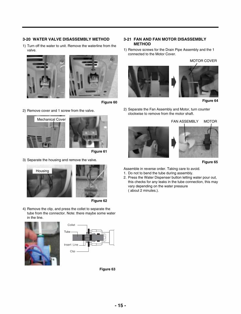
3-20 WATER VALVE DISASSEMBLY METHOD
1) Turn off the water to unit. Remove the waterline from thevalve.
3-21 FAN AND FAN MOTOR DISASSEMBLYMETHOD
1) Remove screws for the Drain Pipe Assembly and the 1connected to the Motor Cover.
2) Remove cover and 1 screw from the valve.
3) Separate the housing and remove the valve.
4) Remove the clip, and press the collet to separate thetube from the connector. Note: there maybe some waterin the line.
Mechanical Cover
Housing
MOTOR COVER
2) Separate the Fan Assembly and Motor, turn counterclockwise to remove from the motor shaft.
FAN ASSEMBLY MOTOR
Assemble in reverse order. Taking care to avoid.1. Do not to bend the tube during assembly.2. Press the Water Dispenser button letting water pour out,
this checks for any leaks in the tube connection, this mayvary depending on the water pressure ( about 2 minutes.).
Figure 60
Figure 61
Figure 62
Figure 63
Figure 64
Figure 65
- 16 -
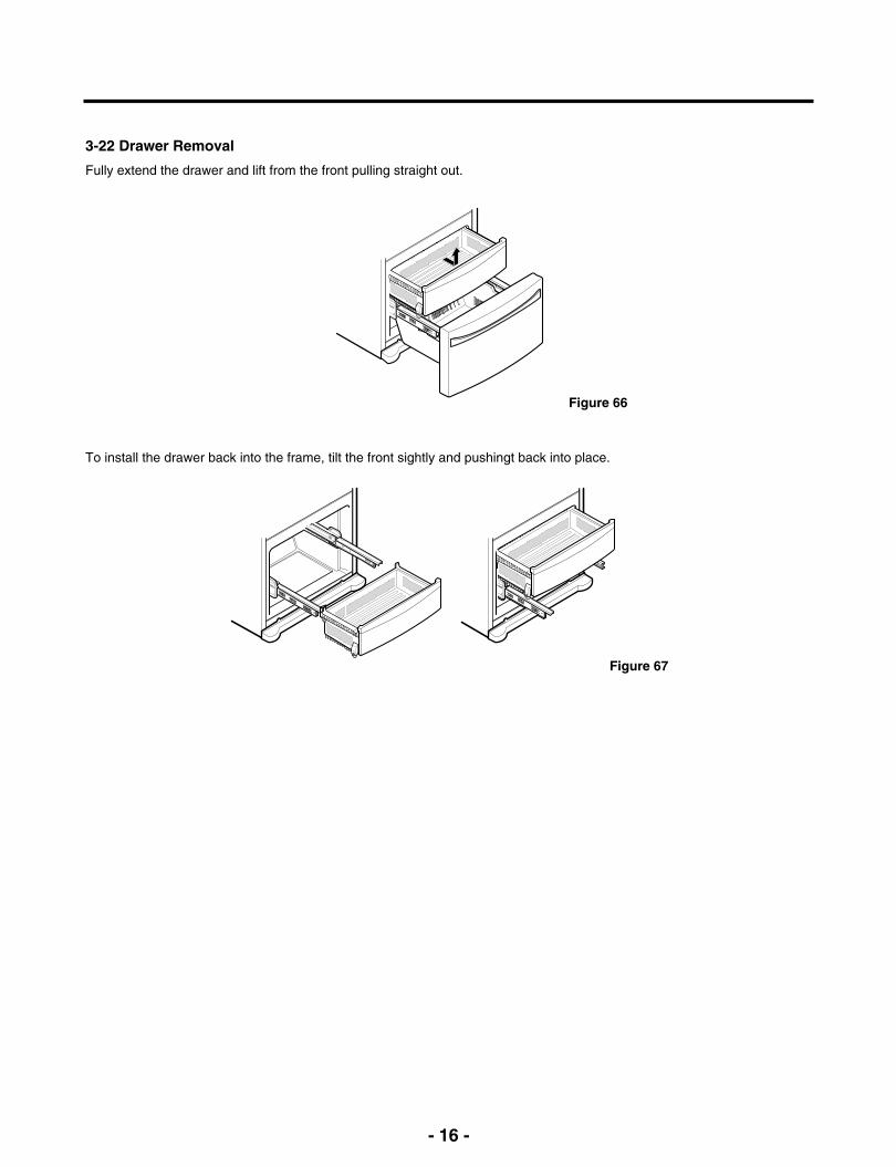
3-22 Drawer Removal
Fully extend the drawer and lift from the front pulling straight out.
To install the drawer back into the frame, tilt the front sightly and pushingt back into place.
Figure 66
Figure 67
- 17 -
4-2-3 Compressor protection logicSince linear Comp conducts linear reciprocating motion,we have protection logic for compressor, motor and PCBas the below.
- Stroke TripDuring the operation, if stroke is above the target value,decrease the target volt by 3V.
- Current TripCurrent trip is set in order to protect compressormechanical part and drive from the overcurrent that mightarise during the operation.Check the current for every 416.7us and if the Tripexceeds 1.86Arms more than three times at Comp ON,forcibly stop and restart six minutes later.
- Lock Piston TripIf stroke is under 5mm even if the current is more than14Arms, Take it as ‘piston lock’ and restart after 2’30” ofComp OFF. Check the current and stroke for every416.7us and if the condition fits more than three times atComp ON, the Trip occurs.
- IPM fault TripIt occurs if FO signal received from IPM is LOW. Forevery 416.7us, check whether FO signal is LOW. The tripoccurs if it is found three times during the fiveperiods(83ms).
4. ADJUSTMENT
4-1-1 Role
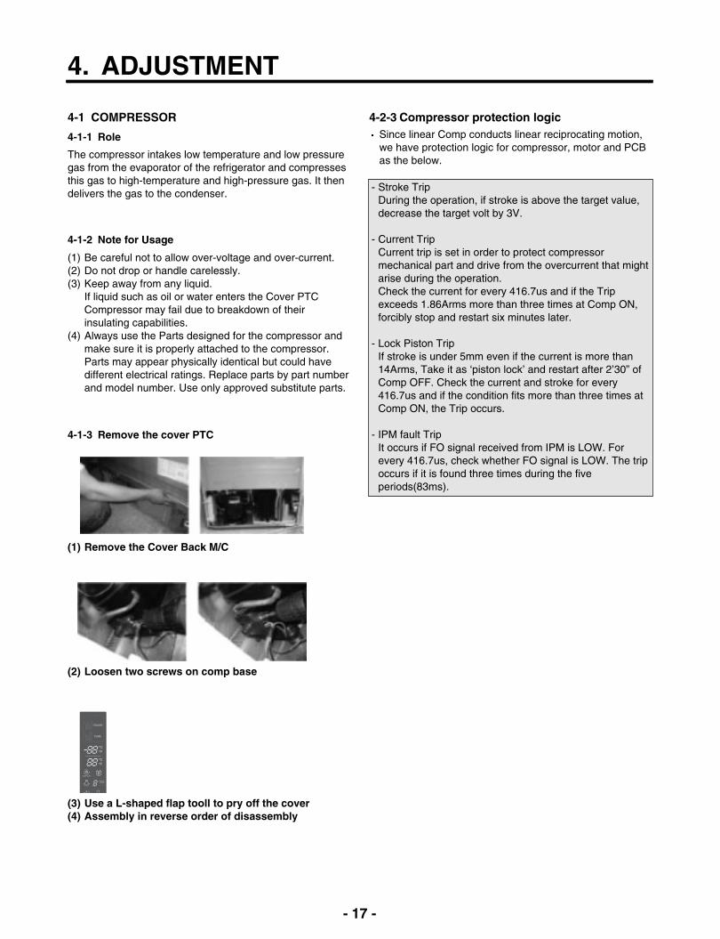
4-1 COMPRESSOR
The compressor intakes low temperature and low pressuregas from the evaporator of the refrigerator and compressesthis gas to high-temperature and high-pressure gas. It thendelivers the gas to the condenser.
4-1-2 Note for Usage
(1) Be careful not to allow over-voltage and over-current.(2) Do not drop or handle carelessly.(3) Keep away from any liquid.
If liquid such as oil or water enters the Cover PTCCompressor may fail due to breakdown of theirinsulating capabilities.
(4) Always use the Parts designed for the compressor andmake sure it is properly attached to the compressor.Parts may appear physically identical but could havedifferent electrical ratings. Replace parts by part numberand model number. Use only approved substitute parts.
4-1-3 Remove the cover PTC
(1) Remove the Cover Back M/C
(2) Loosen two screws on comp base
(3) Use a L-shaped flap tooll to pry off the cover(4) Assembly in reverse order of disassembly

- 18 -
5. CIRCUIT DIAGRAM
LFX28978**
- 19 -
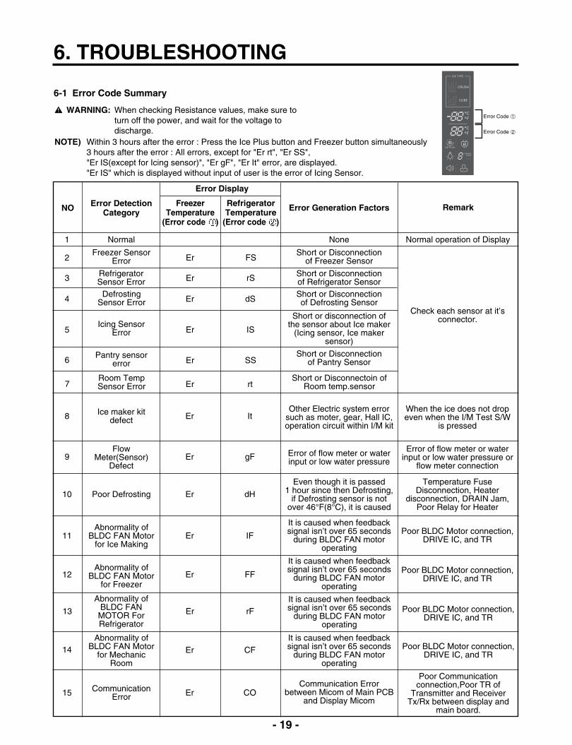
6. TROUBLESHOOTING
6-1 Error Code Summary
WARNING: When checking Resistance values, make sure toturn off the power, and wait for the voltage todischarge.
NOTE) Within 3 hours after the error : Press the Ice Plus button and Freezer button simultaneously3 hours after the error : All errors, except for "Er rt", "Er SS", "Er IS(except for Icing sensor)", "Er gF", "Er It" error, are displayed. "Er IS" which is displayed without input of user is the error of Icing Sensor.
NO Error DetectionCategory
1 Normal None Normal operation of Display
2Freezer Sensor
Error Er FSShort or Disconnection
of Freezer Sensor
3 RefrigeratorSensor Error Er rS Short or Disconnection
of Refrigerator Sensor
Check each sensor at it’sconnector.
Error Generation Factors Remark
Error Display
4Defrosting
Sensor Error Er dSShort or Disconnectionof Defrosting Sensor
5Icing Sensor
Error Er IS
Short or disconnection of the sensor about Ice maker
(Icing sensor, Ice makersensor)
6Pantry sensor
error Er SSShort or Disconnection
of Pantry Sensor
10 Poor Defrosting Er dH
Even though it is passed 1 hour since then Defrosting,
if Defrosting sensor is notover 46°F(8°C), it is caused
Temperature FuseDisconnection, Heater
disconnection, DRAIN Jam,Poor Relay for Heater
8 Ice maker kitdefect Er It
Other Electric system errorsuch as moter, gear, Hall IC,operation circuit within I/M kit
When the ice does not dropeven when the I/M Test S/W
is pressed
9Flow
Meter(Sensor)Defect
Er gF Error of flow meter or waterinput or low water pressure
Error of flow meter or waterinput or low water pressure or
flow meter connection
11Abnormality of
BLDC FAN Motorfor Ice Making
Er IF
It is caused when feedbacksignal isn’t over 65 seconds
during BLDC FAN motoroperating
Poor BLDC Motor connection,DRIVE IC, and TR
12Abnormality of
BLDC FAN Motorfor Freezer
Er FF
It is caused when feedbacksignal isn’t over 65 seconds
during BLDC FAN motoroperating
Poor BLDC Motor connection,DRIVE IC, and TR
14Abnormality of
BLDC FAN Motorfor Mechanic
Room
Er CFIt is caused when feedbacksignal isn’t over 65 seconds
during BLDC FAN motoroperating
Poor BLDC Motor connection,DRIVE IC, and TR
15 CommunicationError Er CO
Communication Errorbetween Micom of Main PCB
and Display Micom
Poor Communicationconnection,Poor TR of
Transmitter and ReceiverTx/Rx between display and
main board.
7Room TempSensor Error Er rt
Short or Disconnectoin ofRoom temp.sensor
13
Abnormality ofBLDC FANMOTOR ForRefrigerator
Er rFIt is caused when feedbacksignal isn’t over 65 seconds
during BLDC FAN motoroperating
Poor BLDC Motor connection,DRIVE IC, and TR
FreezerTemperature
(Error code )
RefrigeratorTemperature
(Error code )
- 20 -
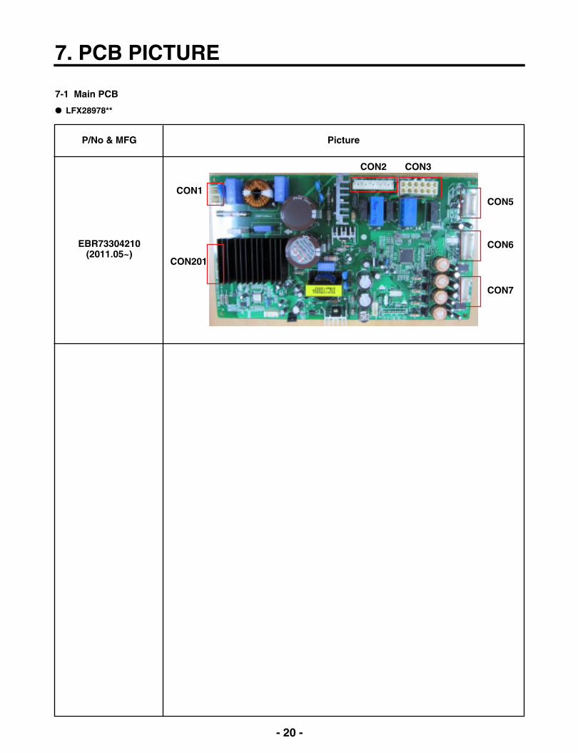
7. PCB PICTURE
7-1 Main PCB
P/No & MFG
EBR73304210(2011.05~)
Picture
CON1
CON201
CON5
CON2
CON6
CON7
CON3
LFX28978**

- 21 -
7-2 Display PCB & Sub PCB
P/No
Display PCBEBR65749303
(2011.05~)
Sub PCBEBR60070707
(2010.02~)
Picture
CON2
CON103 CON102 CON101

- 22 -
8. Troubleshooting With Error Display
0 Ω
OFF
Other
Short
Open
Normal
Change the sensor
Replace the refrigerator
Check the Temp andresistance (Table-1)
Result SVC Action
8-1 Freezer Sensor Error (Er FS)
No
1
2
Checking flow
Check for a loose connection.
Check the Blue/White to Blue/White atCON7 on the main PCB
Result & SVC Action
<CON7>
<Temperature table-1>
(1) To (2)
-22°F / -30°C
-13°F / -25°C
-4°F / -20°C
5°F / -15°C
14°F / -10°C
23°F / -5°C
32°F / 0°C
Result
40
30
23
17
13
10
8
※ The sensor is determined by the temperature.For example, 23 indicates -4°F.
- 23 -
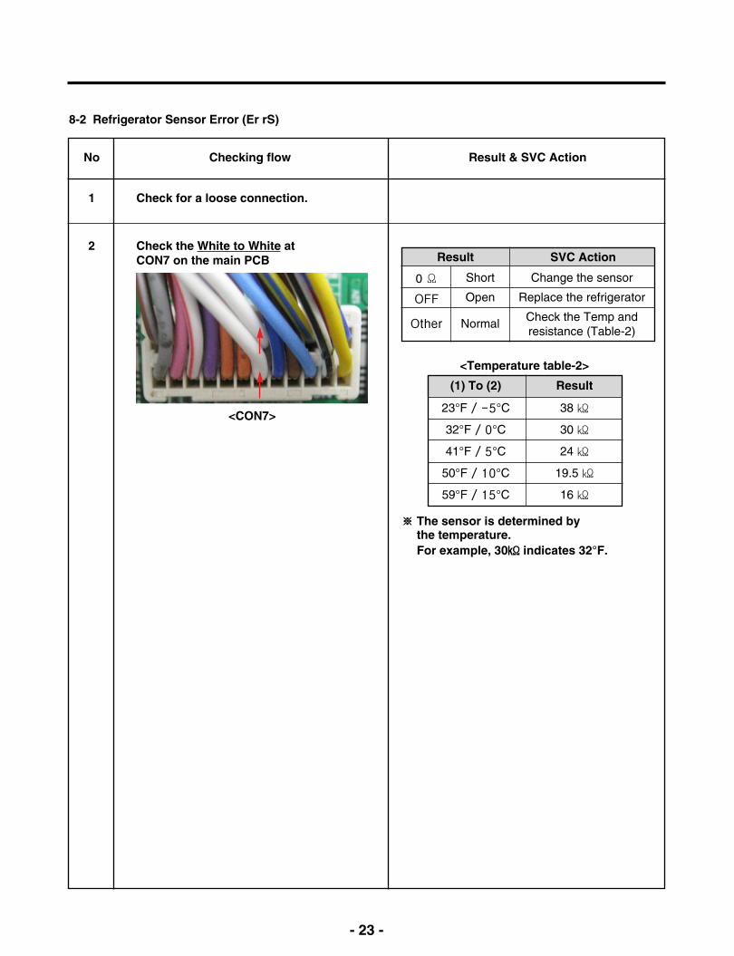
0 Ω
OFF
Other
Short
Open
Normal
Change the sensor
Replace the refrigerator
Check the Temp andresistance (Table-2)
Result SVC Action
8-2 Refrigerator Sensor Error (Er rS)
No
1
2
Checking flow
Check for a loose connection.
Check the White to White atCON7 on the main PCB
Result & SVC Action
<Temperature table-2>
(1) To (2)
23°F / -5°C
32°F / 0°C
41°F / 5°C
50°F / 10°C
59°F / 15°C
Result
38
30
24
19.5
16
※ The sensor is determined by the temperature.For example, 30 indicates 32°F.
<CON7>
- 24 -
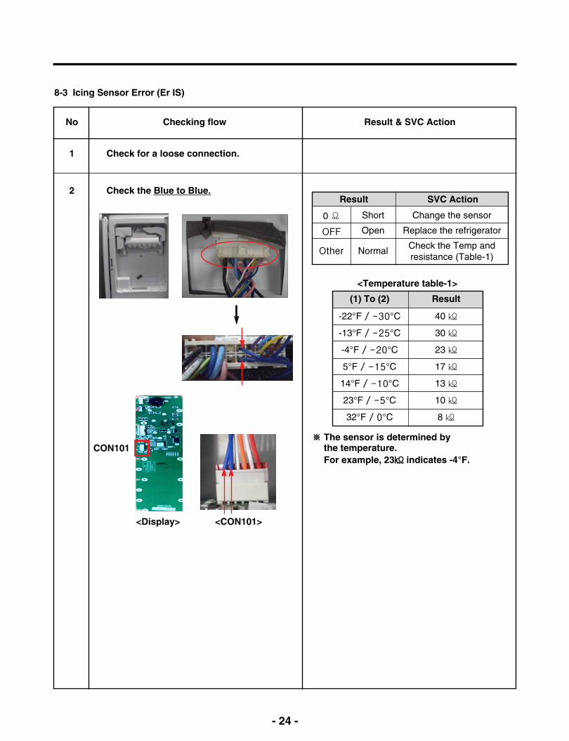
8-3 Icing Sensor Error (Er IS)
0 Ω
OFF
Other
Short
Open
Normal
Change the sensor
Replace the refrigerator
Check the Temp andresistance (Table-1)
Result SVC Action
No
1
2
Checking flow
Check for a loose connection.
Check the Blue to Blue.
Result & SVC Action
<Temperature table-1>
(1) To (2)
-22°F / -30°C
-13°F / -25°C
-4°F / -20°C
5°F / -15°C
14°F / -10°C
23°F / -5°C
32°F / 0°C
Result
40
30
23
17
13
10
8
※ The sensor is determined by the temperature.For example, 23 indicates -4°F.
<CON101><Display>
CON101

- 25 -
0 Ω
OFF
Other
Short
Open
Normal
Change the sensor
Replace the refrigerator
Check the Temp andresistance (Table-3)
Result SVC Action
8-4 Defrost Sensor Error (F dS)
No
1
2
Checking flow
Check for a loose connection.
Check the Orange to Orange.
Result & SVC Action
Check the Brown to Brown atCON7 on the main PCB
<CON7>
<Temperature table-3>
(1) To (2)
23°F / -5°C
32°F / 0°C
41°F / 5°C
50°F / 10°C
59°F / 15°C
Result
38
30
24
19.5
16
※ The sensor is determined by the temperature.For example, 30 indicates 32°F.
- 26 -
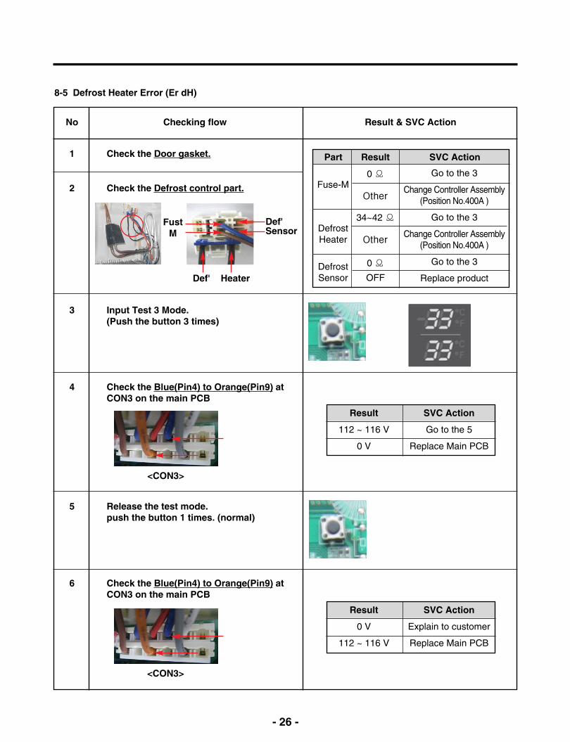
8-5 Defrost Heater Error (Er dH)
Fuse-M
DefrostHeater
DefrostSensor
0 Ω
Other
34~42 Ω
Other
0 Ω
OFF
Go to the 3
Change Controller Assembly(Position No.400A )
Go to the 3
Change Controller Assembly(Position No.400A )
Go to the 3
Replace product
Part Result SVC Action
No
1
2
Checking flow
Check the Door gasket.
Check the Defrost control part.
3 Input Test 3 Mode.(Push the button 3 times)
4 Check the Blue(Pin4) to Orange(Pin9) atCON3 on the main PCB
Result & SVC Action
Def' Heater
FustM
Def'Sensor
5 Release the test mode. push the button 1 times. (normal)
<CON3>
Result
112 ~ 116 V
0 V
SVC Action
Go to the 5
Replace Main PCB
6 Check the Blue(Pin4) to Orange(Pin9) atCON3 on the main PCB
Result
0 V
112 ~ 116 V
SVC Action
Explain to customer
Replace Main PCB
<CON3>

- 27 -
8-6 Freezer Fan Error (Er FF)
No
1
2
Checking flow
Reset the unit and Input Test 1 Mode.(Push the button 1 time)
Open the freezer door and Check the airflow.※ While an error code is displayed, thefan is not working.
3 Check the Fan motor. Rotate fan using your hand.It feel sticky, change the motor.(cause of ice or rust inside of motor)
4 Check the Fan motor voltage.
Result & SVC Action
Below 7 V
0 or 5 V
(2) ~ (3)
(1) ~ (3)
Change the PCB
Change the motor
Point Result SVC Action
Status
No windy
Windy
SVC Action
Go to 3
Go to 4
<CON7>
(1)Pin8, (2)Pin10, (3)Pin12
- 28 -
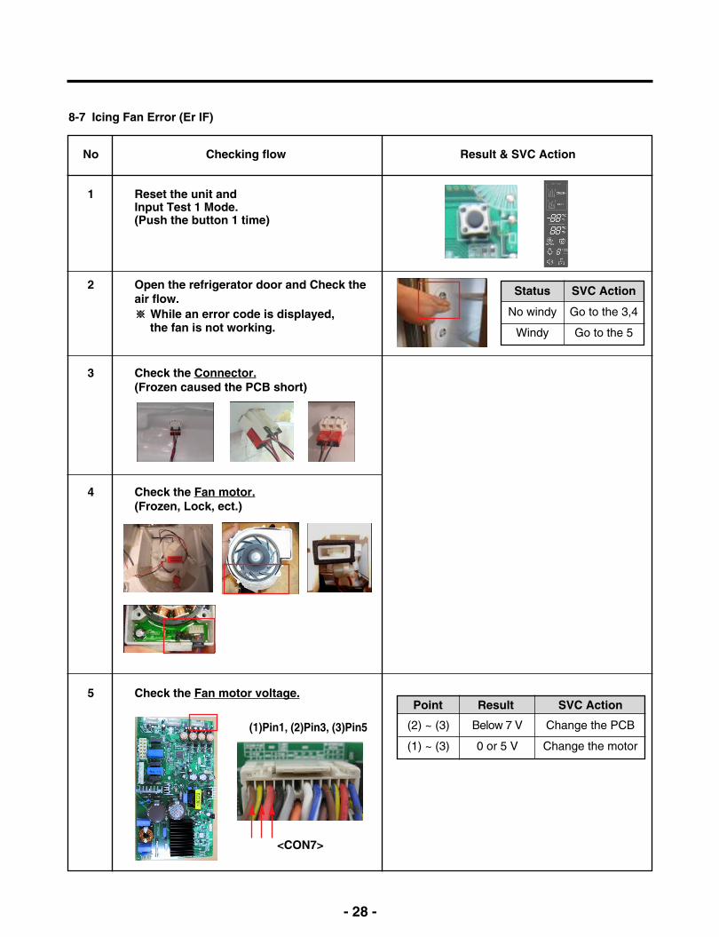
8-7 Icing Fan Error (Er IF)
No
1
2
Checking flow
Reset the unit and Input Test 1 Mode.(Push the button 1 time)
Open the refrigerator door and Check theair flow.※ While an error code is displayed,
the fan is not working.
3 Check the Connector.(Frozen caused the PCB short)
Result & SVC Action
Status
No windy
Windy
SVC Action
Go to the 3,4
Go to the 5
4 Check the Fan motor.(Frozen, Lock, ect.)
5 Check the Fan motor voltage.
Below 7 V
0 or 5 V
(2) ~ (3)
(1) ~ (3)
Change the PCB
Change the motor
Point Result SVC Action
<CON7>
(1)Pin1, (2)Pin3, (3)Pin5
- 29 -
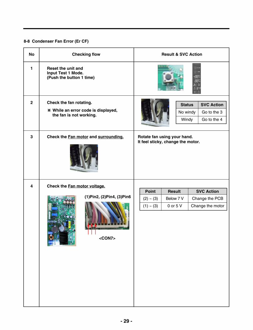
8-8 Condenser Fan Error (Er CF)
No
1
2
Checking flow
Reset the unit and Input Test 1 Mode.(Push the button 1 time)
Check the fan rotating.
※ While an error code is displayed,the fan is not working.
3 Check the Fan motor and surrounding. Rotate fan using your hand.It feel sticky, change the motor.
Result & SVC Action
4 Check the Fan motor voltage.
Status
No windy
Windy
SVC Action
Go to the 3
Go to the 4
Below 7 V
0 or 5 V
(2) ~ (3)
(1) ~ (3)
Change the PCB
Change the motor
Point Result SVC Action
<CON7>
(1)Pin2, (2)Pin4, (3)Pin6
- 30 -
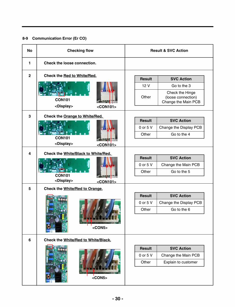
8-9 Communication Error (Er CO)
No
1
2
Checking flow
Check the loose connection.
Check the Red to White/Red.
Result & SVC Action
Result
12 V
Other
SVC Action
Go to the 3
Check the Hinge (loose connection)
Change the Main PCB
5 Check the White/Red to Orange.
6 Check the White/Red to White/Black.
<CON101>
3 Check the Orange to White/Red. Result
0 or 5 V
Other
SVC Action
Change the Display PCB
Go to the 4
4 Check the White/Black to White/Red. Result
0 or 5 V
Other
SVC Action
Change the Main PCB
Go to the 5
Result
0 or 5 V
Other
SVC Action
Change the Display PCB
Go to the 6
Result
0 or 5 V
Other
SVC Action
Change the Main PCB
Explain to customer
CON101
<Display>
<CON101>
CON101<Display>
<CON101>
CON101<Display>
<CON5>
<CON5>

- 31 -
9. Troubleshooting Without Error Display
9-1 Cube mode doesn’t work
No
1
2
Checking flow
Check the loose connection on theDispenser PCB
Check the Black to White on the DispenserPCB (While pushing the Ice Button)
Result & SVC Action
<CON2>
3 Check the RED to White Red. (While pushing the lever S/W)
4 Check the resistance value.
<CON1><CON3>
<Ice Maker>
<AC Indoor Motor> <Dispenser Motor>
(2)(1) (3)
(4)
Pushing
Notpushing
112 ~ 115 V
Other
0 ~2 V
Other
Go to the 3
Dispenser PCB
Go to the 3
Dispenser PCB
Ice Button Result SVC Action
Pushing
Notpushing
9 ~ 12 V
Other
0 ~2 V
Other
Go to the 4
Dispenser PCB
Go to the 4
Dispenser PCB
Ice Button Result SVC Action
(1) to (2)
(3) to (4)
31.1 ~ 42.1 Ω
Other
9.9 ~ 12.1 Ω
Other
Explain
Replace<AC Indoor Motor>
Explain
Replace<AC Indoor Motor>
Point Result SVC Action
- 32 -
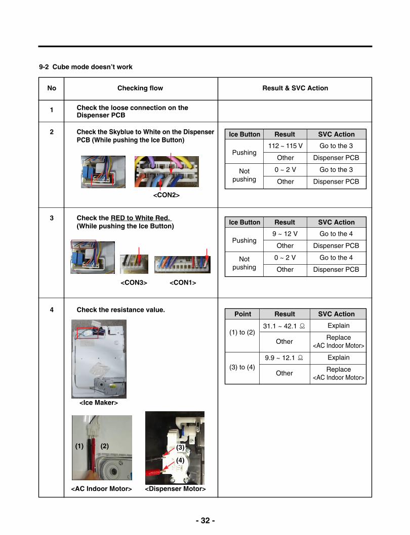
9-2 Cube mode doesn’t work
No
1
2
Checking flow
Check the loose connection on theDispenser PCB
Check the Skyblue to White on the DispenserPCB (While pushing the Ice Button)
Result & SVC Action
<CON2>
3 Check the RED to White Red. (While pushing the Ice Button)
4 Check the resistance value.
<CON1><CON3>
<Ice Maker>
<AC Indoor Motor> <Dispenser Motor>
(2)(1) (3)
(4)
Pushing
Notpushing
112 ~ 115 V
Other
0 ~ 2 V
Other
Go to the 3
Dispenser PCB
Go to the 3
Dispenser PCB
Ice Button Result SVC Action
Pushing
Notpushing
9 ~ 12 V
Other
0 ~ 2 V
Other
Go to the 4
Dispenser PCB
Go to the 4
Dispenser PCB
Ice Button Result SVC Action
(1) to (2)
(3) to (4)
31.1 ~ 42.1 Ω
Other
9.9 ~ 12.1 Ω
Other
Explain
Replace<AC Indoor Motor>
Explain
Replace<AC Indoor Motor>
Point Result SVC Action

- 33 -
<CON2>
9-3 Water mode doesn’t work
No
1
2
Checking flow
Check the loose connection on theDispenser PCB
Check the Purple to White on the DispenserPCB (While pushing the Water Button)
Result & SVC Action
Pushing
Notpushing
112 ~ 115 V
Other
0 ~2 V
Other
Go to the 3
Dispenser PCB
Go to the 3
Dispenser PCB
Water Button Result SVC Action
(3) (4)
4 Check the resistance value.
<Pilot Valve>Machine Room
<Water Valve>In door
(1) to (2)
(3) to (4)
360 ~ 420Ω
Other
360 ~ 420Ω
Other
Explain
ReplacePilot Valve
Explain
ReplaceWater Valve
Point Result SVC Action
(1) (2)
Dispenser Ice Maker
<CON3>
3 Check the Blue to Gray on the DispenserPCB (While pushing the Water Button)
Pushing
Notpushing
112 ~ 115 V
Other
0 ~2 V
Other
Go to the 4
Dispenser PCB
Go to the 4
Dispenser PCB
Water Button Result SVC Action
- 34 -
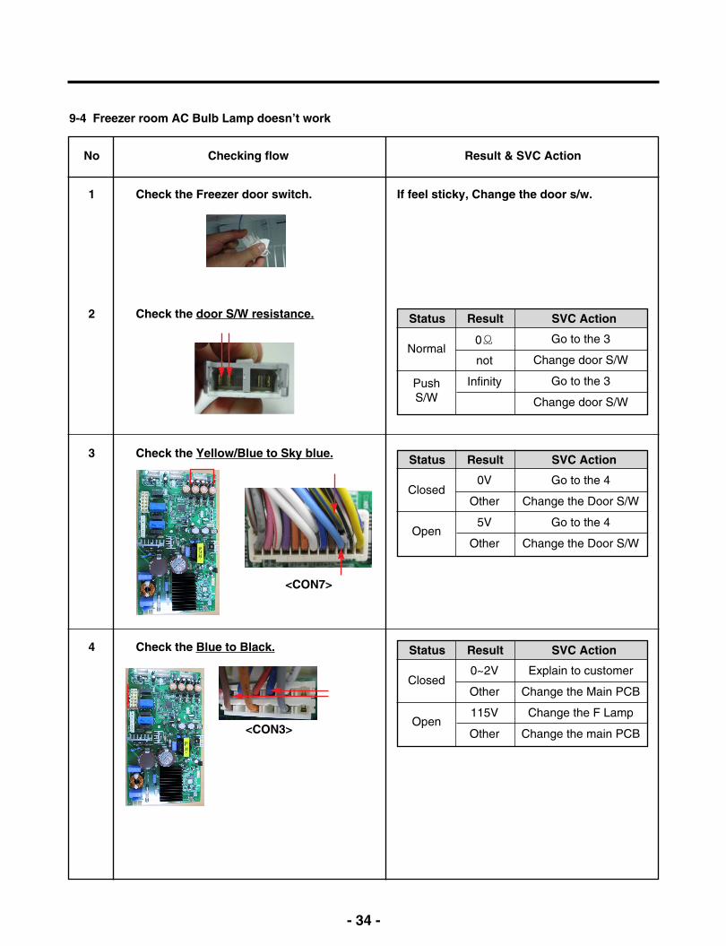
9-4 Freezer room AC Bulb Lamp doesn’t work
No
1
Checking flow
Check the Freezer door switch. If feel sticky, Change the door s/w.
Result & SVC Action
2 Check the door S/W resistance.
3 Check the Yellow/Blue to Sky blue.
4 Check the Blue to Black.
Normal
PushS/W
0Ω
not
Infinity
Go to the 3
Change door S/W
Go to the 3
Change door S/W
Status Result SVC Action
Closed
Open
0V
Other
5V
Other
Go to the 4
Change the Door S/W
Go to the 4
Change the Door S/W
Status Result SVC Action
Closed
Open
0~2V
Other
115V
Other
Explain to customer
Change the Main PCB
Change the F Lamp
Change the main PCB
Status Result SVC Action
<CON7>
<CON3>
- 35 -
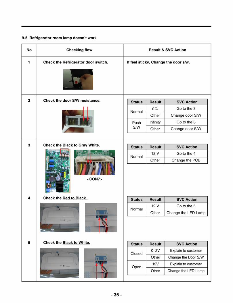
9-5 Refrigerator room lamp doesn’t work
No
1
Checking flow
Check the Refrigerator door switch. If feel sticky, Change the door s/w.
Result & SVC Action
2 Check the door S/W resistance.
3 Check the Black to Gray White.
4 Check the Red to Black.
Closed
Open
0~2V
Other
12V
Other
Explain to customer
Change the Door S/W
Explain to customer
Change the LED Lamp
Status Result SVC Action
Normal
PushS/W
0Ω
Other
Infinity
Other
Go to the 3
Change door S/W
Go to the 3
Change door S/W
Status Result SVC Action
Normal12 V
Other
Go to the 4
Change the PCB
Status Result SVC Action
Normal12 V
Other
Go to the 5
Change the LED Lamp
Status Result SVC Action
5 Check the Black to White.
<CON7>

- 36 -
9-6 Poor cooling in Refrigerator room
No
1
Checking flow
Check R-Sensor resistance.
2 Reset the unit and Input Test 1 Mode.(Push the button 1 time)
3 Open the fresh food door and Check theair flow.
※ R-Sensor is determined by the temperature.For example, 30 indicates 32°F.
Result & SVC Action
Temperature
23°F / -5°C
32°F / 0°C
41°F / 5°C
50°F / 10°C
59°F / 15°C
Result
38
30
24
19.5
16
Status
Windy
No windy
SVC Action
Go to the 4
Check the F Fan motorCheck the Damper
(Go to the 5)
4 Check the air temperature.Cold or not ?
Status
Cold
Not cold
SVC Action
Explain to customer
Check the CompressorAnd sealed system
<CON7>
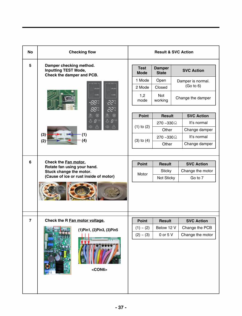
No
5
Checking flow
Damper checking method.Inputting TEST Mode, Check the damper and PCB.
6 Check the Fan motor.Rotate fan using your hand.Stuck change the motor.(Cause of ice or rust inside of motor)
Result & SVC Action
(1)(3)
(2) (4)
Open
Closed
Notworking
1 Mode
2 Mode
1,2mode
Damper is normal.(Go to 6)
Change the damper
TestMode
DamperState SVC Action
(1) to (2)
(3) to (4)
270 ~330Ω
Other
270 ~330Ω
Other
It’s normal
Change damper
It’s normal
Change damper
Point Result SVC Action
Below 12 V
0 or 5 V
(1) ~ (2)
(2) ~ (3)
Change the PCB
Change the motor
Point Result SVC Action
Sticky
Not StickyMotor
Change the motor
Go to 7
Point Result SVC Action
- 37 -
<CON6>
(1)Pin1, (2)Pin3, (3)Pin5
7 Check the R Fan motor voltage.

- 38 -
9-7 Poor cooling in Freezer compartment
No
1
Checking flow
Check the F Sensor resistance
2 Reset the unit and Input Test 1 Mode.(Push the button 1 time)
3 Open the freezer door and Check the airflow.
※ The F Sensor is determined by the temperature.For example, 23 indicate -4°F.
Result & SVC Action
Temperature
-22°F / -30°C
-13°F / -25°C
-4°F / -20°C
5°F / -15°C
14°F / -10°C
23°F / -5°C
32°F / 0°C
Result
40
30
23
17
13
10
8
Status
Windy
No windy
SVC Action
Go to the 4
Check the F Fan motor
4 Check the air temperature.Cold or not ?
Status
Cold
Not cold
SVC Action
Explain to customer
Check the CompressorAnd sealed system
<CON7>
- 39 -
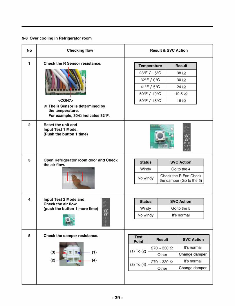
9-8 Over cooling in Refrigerator room
No
1
Checking flow
Check the R Sensor resistance.
2 Reset the unit and Input Test 1 Mode.(Push the button 1 time)
3 Open Refrigerator room door and Checkthe air flow.
※ The R Sensor is determined by the temperature.For example, 30 indicates 32°F.
Result & SVC Action
Status
Windy
No windy
SVC Action
Go to the 4
Check the R Fan Checkthe damper (Go to the 5)
4 Input Test 2 Mode andCheck the air flow.(push the button 1 more time)
Status
Windy
No windy
SVC Action
Go to the 5
It’s normal
5 Check the damper resistance.
<CON7>
Temperature
23°F / -5°C
32°F / 0°C
41°F / 5°C
50°F / 10°C
59°F / 15°C
Result
38
30
24
19.5
16
(1)
(4)
(3)
(2)
(1) To (2)
(3) To (4)
270 ~ 330 Ω
Other
270 ~ 330 Ω
Other
It’s normal
Change damper
It’s normal
Change damper
Result SVC ActionTestPoint

- 40 -
10. Reference
※ After measure the values, you should put in the TPA again.
10-1 TEST MODE and Removing TPA
1. How to enter the TEST MODEPush the test button on the Main PCB to enter the TEST MODE.
2. How to remove Terminal Position Assurance (TPA)
* 1 time : Comp / Damper / All FAN on(Everything is displayed)
* 2 times : Damper closed (22 22 displayed)
* 3 times : Forced defrost mode(33 33 displayed)
Main PWB
<AC TPA> <DC TPA>
- 41 -
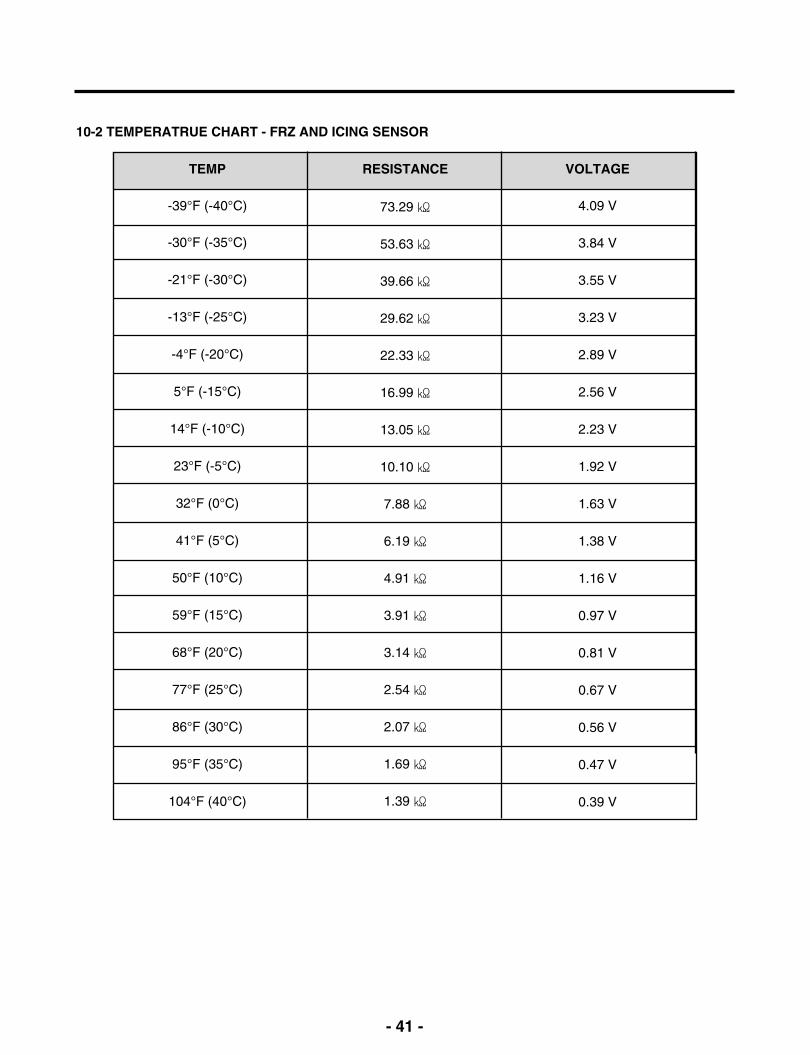
10-2 TEMPERATRUE CHART - FRZ AND ICING SENSOR
TEMP
-39°F (-40°C)
-30°F (-35°C)
-21°F (-30°C)
-13°F (-25°C)
-4°F (-20°C)
5°F (-15°C)
14°F (-10°C)
23°F (-5°C)
32°F (0°C)
41°F (5°C)
50°F (10°C)
59°F (15°C)
68°F (20°C)
77°F (25°C)
86°F (30°C)
95°F (35°C)
104°F (40°C)
RESISTANCE
73.29
53.63
39.66
29.62
22.33
16.99
13.05
10.10
7.88
6.19
4.91
3.91
3.14
2.54
2.07
1.69
1.39
VOLTAGE
4.09 V
3.84 V
3.55 V
3.23 V
2.89 V
2.56 V
2.23 V
1.92 V
1.63 V
1.38 V
1.16 V
0.97 V
0.81 V
0.67 V
0.56 V
0.47 V
0.39 V
- 42 -
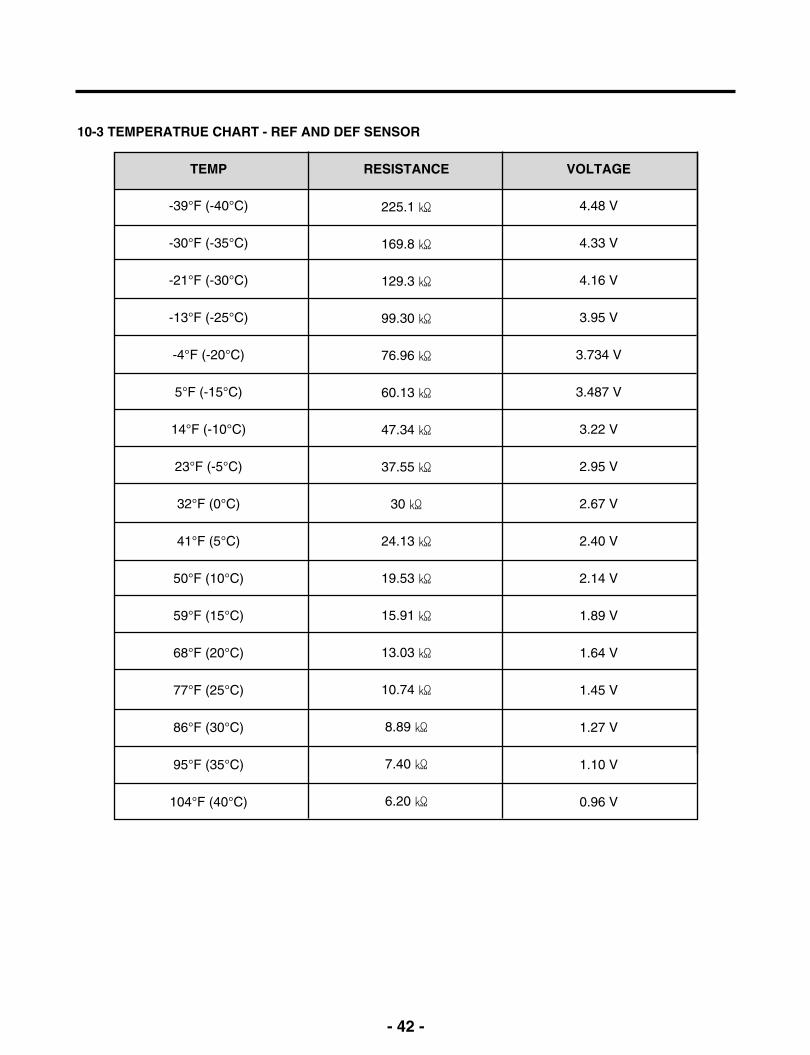
10-3 TEMPERATRUE CHART - REF AND DEF SENSOR
TEMP
-39°F (-40°C)
-30°F (-35°C)
-21°F (-30°C)
-13°F (-25°C)
-4°F (-20°C)
5°F (-15°C)
14°F (-10°C)
23°F (-5°C)
32°F (0°C)
41°F (5°C)
50°F (10°C)
59°F (15°C)
68°F (20°C)
77°F (25°C)
86°F (30°C)
95°F (35°C)
104°F (40°C)
RESISTANCE
225.1
169.8
129.3
99.30
76.96
60.13
47.34
37.55
30
24.13
19.53
15.91
13.03
10.74
8.89
7.40
6.20
VOLTAGE
4.48 V
4.33 V
4.16 V
3.95 V
3.734 V
3.487 V
3.22 V
2.95 V
2.67 V
2.40 V
2.14 V
1.89 V
1.64 V
1.45 V
1.27 V
1.10 V
0.96 V

- 43 -
10-4 How to check the Fan-Error
(1) EBR650027**After sending a signal to the fan, the MICOM checks the BLDC fanmotor s lock status. If there is no feedback signal from the BLDC fan,the fan motor stops for 10 seconds and then is powered again for 15seconds. To determine that there is a fan motor malfunction,this process is repeated 3 times. If the fan motor is determined to bedefective, the error code will be shown in the display for 30 minutes.At this point, the process will be repeated until the fan motor operatesnormally. If normal operation is achieved, the error display is erased andthe MICOM is reset automatically.
No signal Error Display
15s
10s
15s
10s
15s
Normal drive
No signal Repeat
20s
10s
15s
10s Pause 30minPause 30min 10s
15s 20s

- 44 -
11. COMPONENT TESTING INFORMATION
11-1 Defrost Controller Assembly
Function The controller assembly is made up of two different kinds of parts. The fuse and the sensor. To determine if these parts are defective, check for resistance. The fuse will cut power to thedefrost heater at very high temperatures.
How toMeasure(Fuse-M)
Set a ohmmeter to the 2 housing pin.Measure the 2 pin connected to Fuse-M.If the ohmmeter indicate below 0.1ohmfuse-m is a good condition, But if infinite thepart is bad.
How toMeasure(Sensor)
Set a ohmmeter to The 2housing pin.Measure the 2 pin connected to Sensor.If the ohmmeter indicate 11 (at roomtemperature) Sensor is good.When check the ohm at other temperaturesCheck the sensor manual.
Standard Sensor (at room temperature)
Test Point
(1) to (2)
Ressult
11Ω
Fuse-M (at all temperature)
Test Point
(1) to (2)
Ressult
0 ~ 0.1Ω
(1) to (2)
(1) to (2)

- 45 -
11-2 Sheath Heater
Function Sheath heater is a part for defrost. All heating wire is connected to only one line. To check ifthe part is defective, check the resistance.
How toMeasure
Set a ohmmeter connect to The 2 housing pin.Measure the 2 pin connected to Sheath Heater.If the ohmmeter indicate (V°øV)/Watt=R is good condition,ex) when watt=350w, voltage=115v R=(115°ø115)/350=38ΩBut if the ohm meter indicate infinity the Sheath heater is bad.
Standard Sheath heater (at all temperature)
Test Point
(1) to (2)
Ressult
34 ~ 42Ω
(1) (2)
- 46 -
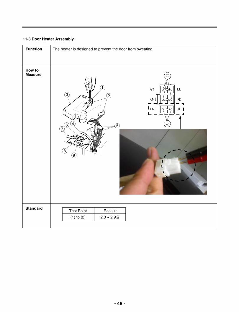
11-3 Door Heater Assembly
Function The heater is designed to prevent the door from sweating.
How toMeasure
StandardTest Point
(1) to (2)
Ressult
2.3 ~ 2.9Ω
1
23
5
89
467
- 47 -
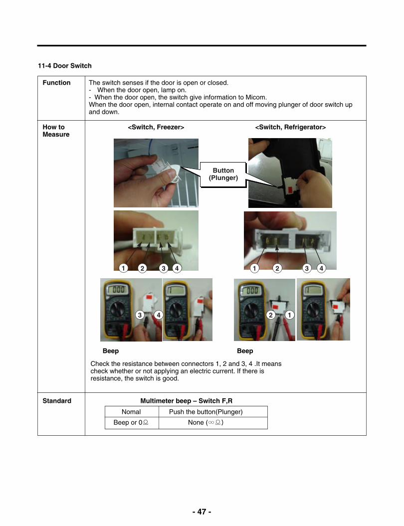
11-4 Door Switch
Function The switch senses if the door is open or closed.- When the door open, lamp on.- When the door open, the switch give information to Micom.When the door open, internal contact operate on and off moving plunger of door switch upand down.
How toMeasure
<Switch, Freezer> <Switch, Refrigerator>
Check the resistance between connectors 1, 2 and 3, 4 .It meanscheck whether or not applying an electric current. If there isresistance, the switch is good.
Standard
Beep Beep
Multimeter beep – Switch F,R
Nomal
Beep or 0Ω
Push the button(Plunger)
None (∞Ω)
Button(Plunger)
1 2 3 4
3 4 2 1
1 2 3 4
- 48 -
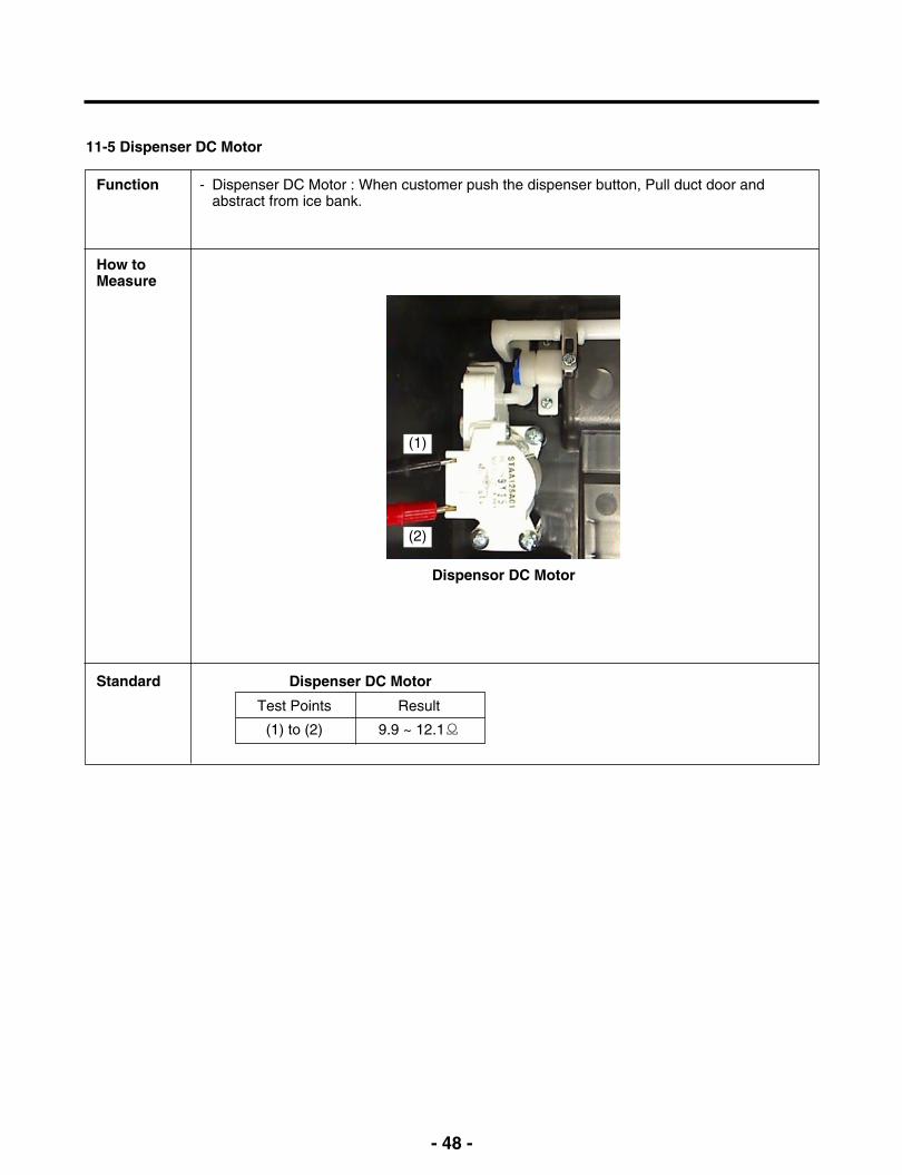
11-5 Dispenser DC Motor
Function - Dispenser DC Motor : When customer push the dispenser button, Pull duct door andabstract from ice bank.
How toMeasure
Standard
Dispensor DC Motor
Dispenser DC Motor
Test Points
(1) to (2)
Result
9.9 ~ 12.1Ω
(1)
(2)

- 49 -
11-6 AC Motor ASSEMBLY
Function The motor in the door pushed the ice into the dispenser.
How toMeasure
< In-door Motor > < In-door Motor >
Standard Geared Motor
Test Points
(1) to (2)
Result
31.1 ~ 42.09Ω
Cube Solenoid
Test Points
(1) to (3)
Result
31.1 ~ 42.09Ω
Separate thehousing.
Measure theresistance between(1) and (2)
Check the resistance between connectors (In-door motor 1, 2) and(In-door motor 1, 3). It means check whether or not applying anElectric current. If there is resistance, it means the geared motor orsolenoid is not inferiority
(1) (2)
(3)(1)
1
2
Separate thehousing.
Measure theresistance between(1) and (3)
1
2
- 50 -
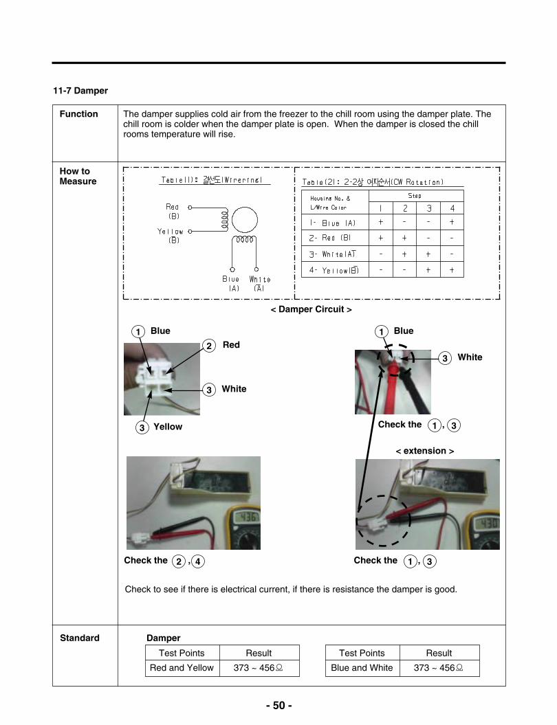
11-7 Damper
Function The damper supplies cold air from the freezer to the chill room using the damper plate. Thechill room is colder when the damper plate is open. When the damper is closed the chillrooms temperature will rise.
How toMeasure
< Damper Circuit >
< extension >
Check the ,
Standard Damper
Test Points
Red and Yellow
Result
373 ~ 456Ω
Test Points
Blue and White
Result
373 ~ 456Ω
Check to see if there is electrical current, if there is resistance the damper is good.
1 Blue 1 Blue
2 Red
3 White
3 White
1 3
Check the , 2 4 Check the , 1 3
3 Yellow

- 51 -
11-8 Lamp Socket
Function The lamp socket connect cover lamp assembly to lamp.The lamp socket fix lamp and unite lamp and cover lamp assembly.The lamp socket supply electric source to lamp also.
How toMeasure
Standard
Check the resistance between connector of housing and connector of lamp socket. It meanscheck whether or not applying an electric current.If there is resistance it means the lamp socket is good.
Test Points
(1) to (2) and (3) to (4)
Result
0Ω
(1) (2)
(3) (4)
- 52 -
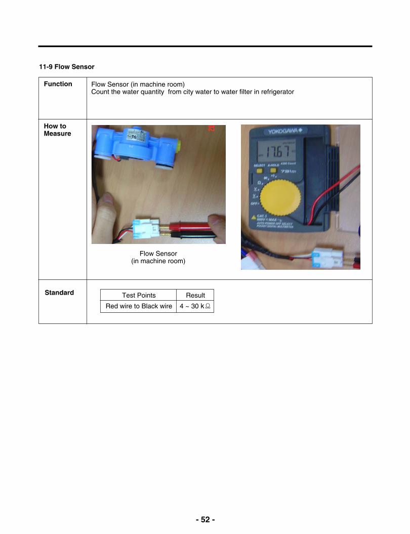
11-9 Flow Sensor
Function Flow Sensor (in machine room)Count the water quantity from city water to water filter in refrigerator
How toMeasure
Standard
Flow Sensor(in machine room)
Test Points
Red wire to Black wire
Result
4 ~ 30 kΩ

- 53 -
12. Compressor Troubleshooting
PCB Check (Simplify)
Test Mode
Power Off Power On PCB OK
Replace Driver PCB
N
YTime>30sec& V≒200
Con201Disconnect
A-inverterTEST 1 Mode
Protection Logic
Check Voltage about 200Vpast 30second after turn on
Troubleshooting
N
Y
N
N
Y
Y
Y
N
NN
Y
Y
Y
N
N
Y
Y N
N
NotCooling
Y N
N
N
N
N
Y
N
YRecheck
LED blink 1
LED blink 7
LED blink 5
LED blink2
LED blink6
Reset
Reset
Reset
Reset
LED blink 1
LED blink 7
Replace Driver PCBComp.Check?
Replace Driver PCB
LED blink 5
LED blink2
Heavy Repair
Heavy Repair
Comp.Work?
Comp.Check? Replace Comp.
Comp.Work?
Comp.Check?
HarnessCheck?
Leakage? Recheck
Reset LED blink6
Heavy Repair
Heavy Repair Recheck
Replace Driver PCBComp.Work?
Comp.Check?
Refrigerantleak ?
IPM output>
80V-20%
Refrigerantleak? Recheck
Fix Harness
Comp.Work?
Comp.Check?
Leakage? Recheck
Reset
Check C
LEDBlink?
Ref.Comp
FC75(A-Inverter)Refer
TEST1 Forced Starting TDC (Full Stroke)
Display & sound
Display ON, Buzz 1 time

- 54 -
12-1 Check A
- There is PC Board located in the PCB case.The control driver is PC board for the compressor.
- This step shows the source voltage of the driver PC board.
* Driver PCB located in machine room.
Step1. Open PCB Cover Step2. Check Driver PCB
- 55 -
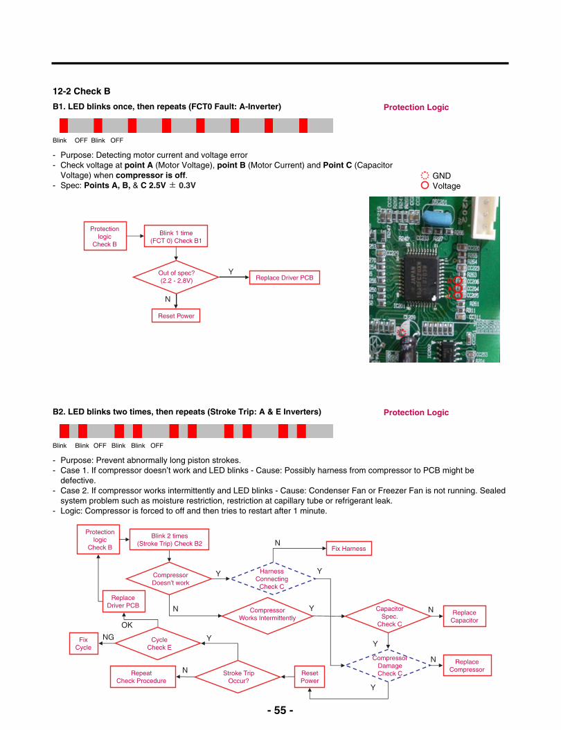
12-2 Check B
B1. LED blinks once, then repeats (FCT0 Fault: A-Inverter)
- Purpose: Detecting motor current and voltage error- Check voltage at point A (Motor Voltage), point B (Motor Current) and Point C (Capacitor
Voltage) when compressor is off.- Spec: Points A, B, & C 2.5V ± 0.3V
Protection Logic
Blink OFF Blink OFF
Y
N
Protectionlogic
Check B
Blink 1 time(FCT 0) Check B1
Out of spec?(2.2 - 2.8V)
Reset Power
Replace Driver PCB
B2. LED blinks two times, then repeats (Stroke Trip: A & E Inverters) Protection Logic
Blink Blink OFF Blink Blink OFF
Y
Y
Y
Y
Protectionlogic
Check B
Blink 2 times(Stroke Trip) Check B2
CompressorDoesn’t work
Y
N CompressorWorks Intermittently
CapacitorSpec.
Check C
CompressorDamageCheck C
ReplaceCapacitor
ReplaceCompressor
N
N
ResetPower
Stroke TripOccur?
Y
RepeatCheck Procedure
HarnessConnecting
Check C
Fix HarnessN
N
CycleCheck E
FixCycle
ReplaceDriver PCB
OK
NG
- Purpose: Prevent abnormally long piston strokes.- Case 1. If compressor doesn’t work and LED blinks - Cause: Possibly harness from compressor to PCB might be
defective.- Case 2. If compressor works intermittently and LED blinks - Cause: Condenser Fan or Freezer Fan is not running. Sealed
system problem such as moisture restriction, restriction at capillary tube or refrigerant leak.- Logic: Compressor is forced to off and then tries to restart after 1 minute.
GNDVoltage

- 56 -
B3. LED blinks five times, then repeats (Locked Piston: A & E Inverters) Protection Logic
Protection Logic
Blink Blink Blink Blink Blink OFF
Protectionlogic
Check B
Blink 5 times(Lock Piston Trip) Check B3
CompressorDoesn’t work
RepeatCheck Procedure
ResetPower
CompressorDoesn’t work
N
Y
ReplaceCompressor
Hi siderestriction
N
Y
SealedsystemRepair
- Purpose: To detect locked piston- Cause: Lack of oil to the cylinder, cylinder or piston damaged and or restricted discharge.
A Locked Piston can also be caused by foreign materials inside the compressor.- Logic: Compressor is forced off and tries to restart within 2.5 minutes.
B4. LED blinks six times, then repeats (Current Trip: A & E-Inverters)
Blink Blink Blink Blink Blink Blink OFF
Protectionlogic
Check B
Blink 6 time(Current Trip) Check B4
CompressorIntermittently
works
Y CapacitorSpec.
Check C2
CompressorDamage
Check C3
ReplaceCapacitor
ReplaceCompressor
NG
NGResetPower
Y
Current tripOccur?
Y
RepeatCheck Procedure
IPMCheck B5
Y
ReplaceDriver PCB
NG
N Y
N
CycleCheck E
Y
FixCycle
- Purpose: Prevent over-current (overload protect)- Cause: Ambient temperature is high (over 43°C) and/or refrigerator’s condenser air movement is restricted.- Condenser Fan is stopped, restricted discharge line, compressor is damaged, or IPM device is defective.- Logic: Compressor is forced off and tries to restart after 6 minutes.
- 57 -
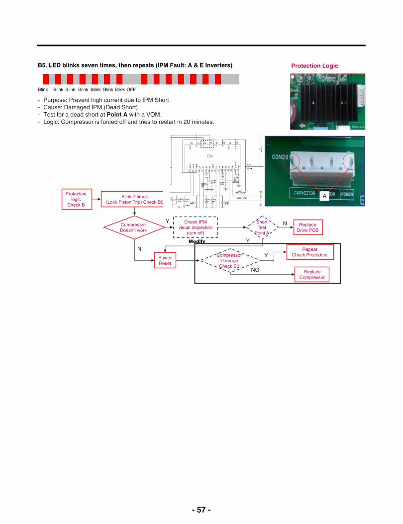
B5. LED blinks seven times, then repeats (IPM Fault: A & E Inverters) Protection Logic
Blink BlinkBlink Blink Blink Blink Blink OFF
Protectionlogic
Check B
Blink 7 times(Lock Piston Trip) Check B5
CompressorDoesn’t work
Y
N RepeatCheck Procedure
ReplaceDrive PCB
N
Y
Check IPMvisual inspection
(turn off)
ShortTest
Point A
PowerReset
CompressorDamage
Check C3Replace
Compressor
NG
Y
Modify
- Purpose: Prevent high current due to IPM Short- Cause: Damaged IPM (Dead Short)- Test for a dead short at Point A with a VOM.- Logic: Compressor is forced off and tries to restart in 20 minutes.
A
- 58 -
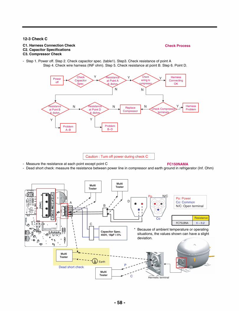
12-3 Check C
C1. Harness Connection CheckC2. Capacitor SpecificationsC3. Compressor Check
- Step 1. Power off. Step 2. Check capacitor spec. (table1). Step3. Check resistance of point AStep 4. Check wire harness (INF ohm). Step 5. Check resistance at point B. Step 6. Point D.
Check Process
Poweroff
Resistanceat Point A6~8ohm
HarnessConnecting
OK
ProblemA~B
CheckCapacitor
Spec.
Resistanceat Point B6~8ohm
Resistanceat Point D6~8ohm
ReplaceCompressor
ProblemB~D
Checkwiring to
compressor
Y
N
N
Y
Y
Y
N
N
Check Compressorterminals
HarnessProblem
YN
Y
- Measure the resistance at each point except point C- Dead short check: measure the resistance between power line in compressor and earth ground in refrigerator (Inf. Ohm)
FC150NAMA
MultiTester
Capacitor Spec.450V, 18μF±5%
MultiTester
MultiTester
MultiTester
Caution : Turn off power during check C
* Because of ambient temperature or operatingsituations, the values shown can have a slightdeviation.
- 59 -
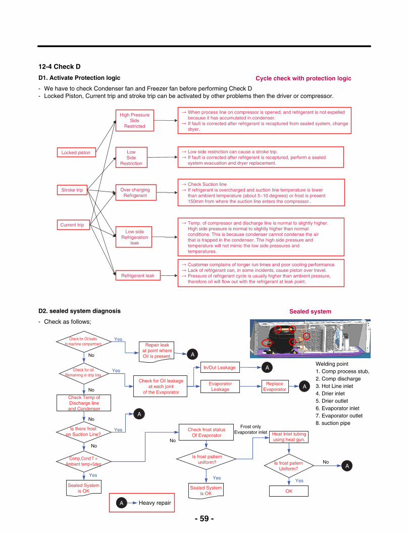
12-4 Check D
D1. Activate Protection logic
- We have to check Condenser fan and Freezer fan before performing Check D- Locked Piston, Current trip and stroke trip can be activated by other problems then the driver or compressor.
Cycle check with protection logic
High PressureSide
Restricted
→ When process line on compressor is opened, and refrigerant is not expelledbecause it has accumulated in condenser.
→ If fault is corrected after refrigerant is recaptured from sealed system, change dryer.
→ Low side restriction can cause a stroke trip.→ If fault is corrected after refrigerant is recaptured, perform a sealed
system evacuation and dryer replacement.
→ Check Suction line→ If refrigerant is overcharged and suction line temperature is lower
than ambient temperature (about 5~10 degrees) or frost is present150mm from where the suction line enters the compressor..
→ Customer complains of longer run times and poor cooling performance.→ Lack of refrigerant can, in some incidents, cause piston over travel.→ Pressure of refrigerant cycle is usually higher than ambient pressure,
therefore oil will flow out with the refrigerant at leak point.
→ Temp. of compressor and discharge line is normal to slightly higher.High side pressure is normal to slightly higher than normalconditions. This is because condenser cannot condense the airthat is trapped in the condenser. The high side pressure andtemperature will not mimic the low side pressures andtemperatures.
Over chargingRefrigerant
Low sideRefrigeration
leak
Locked piston
Current trip
Refrigerant leak
LowSide
Restriction
Stroke trip
D2. sealed system diagnosis
- Check as follows;
Sealed system
No
No
Check for oilRemaining in drip tray
Check for Oil leaksIn machine compartment
Comp,Cond T >Ambient temp+5deg
Check Temp ofDischarge lineand Condenser
Check frost statusOf Evaporator
Is frost patternuniform?
Heat Inlet tubingusing heat gun.
Is frost paternUniform?
OK
YesYes
No
Frost onlyEvaporator inlet
Yes
No
Sealed Systemis OK
Sealed Systemis OK
Repair leakat point whereOil is present.
Yes
Yes
A
In/Out Leakage
EvaporatorLeakage
A
ReplaceEvaporator A
A
Check for Oil leakageat each joint
of the Evaporator
Is there froston Suction Line?
Yes
ANo
No
A Heavy repair
Welding point1. Comp process stub,2. Comp discharge3. Hot Line inlet4. Drier inlet5. Drier outlet6. Evaporator inlet7. Evaporator outlet8. suction pipe
- 60 -
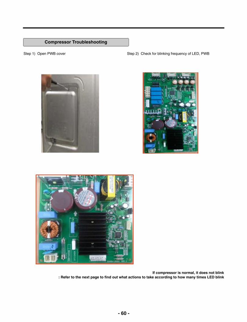
Compressor Troubleshooting
Step 1) Open PWB cover Step 2) Check for blinking frequency of LED, PWB
If compressor is normal, it does not blink : Refer to the next page to find out what actions to take according to how many times LED blink
- 61 -
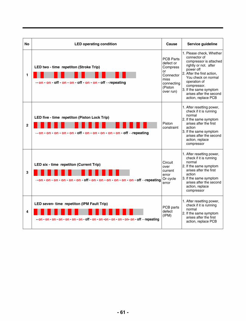
LED two - time repetiton (Stroke Trip)
on - on - off - on - on - off - on - on - off repeating
PCB Partsdefect orCompressorConnectormissconnecting(Pistonover run)
1. Please check, Whetherconnector ofcompressor is attachedrightly or not. afterpower off
2. After the first action,You check on normaloperation ofcompressor.
3. If the same symptomarises after the secondaction, replace PCB
Pistonconstraint
1. After resetting power,check if it is runningnormal
2. If the same symptomarises after the firstaction
3. If the same symptomarises after the secondaction, replacecompressor
CircuitovercurrenterrorOr cycleerror
1. After resetting power,check if it is runningnormal
2. If the same symptomarises after the firstaction
3. If the same symptomarises after the secondaction, replacecompressor
PCB partsdefect(IPM)
1. After resetting power,check if it is runningnormal
2. If the same symptomarises after the firstaction, replace PCB
1
LED five - time repetiton (Piston Lock Trip)
on - on - on - on - on - off - on - on - on - on - on - off repeating
2
LED six - time repetiton (Current Trip)
on - on - on - on - on - on - off - on - on - on - on - on - on - off repeating
3
LED seven- time repetiton (IPM Fault Trip)
on - on - on - on - on - on - on - off - on - on -on - on - on - on- on - off repeating
4
No LED operating condition Cause Service guideline
- 62 -
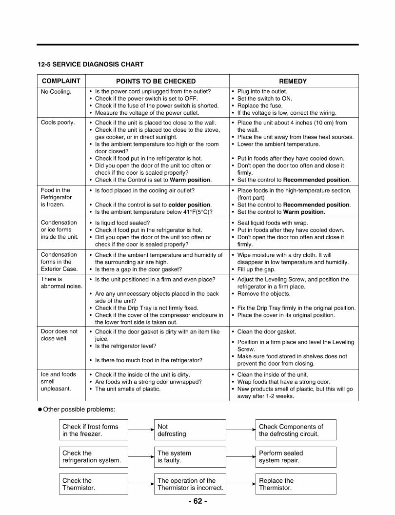
12-5 SERVICE DIAGNOSIS CHART
COMPLAINT POINTS TO BE CHECKED REMEDY
No Cooling. • Is the power cord unplugged from the outlet?• Check if the power switch is set to OFF.• Check if the fuse of the power switch is shorted.• Measure the voltage of the power outlet.
• Plug into the outlet.• Set the switch to ON.• Replace the fuse.• If the voltage is low, correct the wiring.
Cools poorly. • Check if the unit is placed too close to the wall.• Check if the unit is placed too close to the stove,
gas cooker, or in direct sunlight.• Is the ambient temperature too high or the room
door closed?• Check if food put in the refrigerator is hot.• Did you open the door of the unit too often or
check if the door is sealed properly?• Check if the Control is set to Warm position.
• Place the unit about 4 inches (10 cm) fromthe wall.
• Place the unit away from these heat sources.• Lower the ambient temperature.
• Put in foods after they have cooled down.• Don't open the door too often and close it
firmly.• Set the control to Recommended position.
Food in theRefrigeratoris frozen.
• Is food placed in the cooling air outlet?
• Check if the control is set to colder position.• Is the ambient temperature below 41°F(5°C)?
• Place foods in the high-temperature section.(front part)
• Set the control to Recommended position.• Set the control to Warm position.
Condensationor ice formsinside the unit.
• Is liquid food sealed?• Check if food put in the refrigerator is hot.• Did you open the door of the unit too often or
check if the door is sealed properly?
• Seal liquid foods with wrap.• Put in foods after they have cooled down.• Don't open the door too often and close it
firmly.
Condensationforms in theExterior Case.
• Check if the ambient temperature and humidity ofthe surrounding air are high.
• Is there a gap in the door gasket?
• Wipe moisture with a dry cloth. It willdisappear in low temperature and humidity.
• Fill up the gap.
There isabnormal noise.
• Is the unit positioned in a firm and even place?
• Are any unnecessary objects placed in the backside of the unit?
• Check if the Drip Tray is not firmly fixed.• Check if the cover of the compressor enclosure in
the lower front side is taken out.
• Adjust the Leveling Screw, and position therefrigerator in a firm place.
• Remove the objects.
• Fix the Drip Tray firmly in the original position.• Place the cover in its original position.
Door does notclose well.
• Check if the door gasket is dirty with an item likejuice.
• Is the refrigerator level?
• Is there too much food in the refrigerator?
• Clean the door gasket.
• Position in a firm place and level the LevelingScrew.
• Make sure food stored in shelves does notprevent the door from closing.
Ice and foodssmellunpleasant.
• Check if the inside of the unit is dirty.• Are foods with a strong odor unwrapped?• The unit smells of plastic.
• Clean the inside of the unit.• Wrap foods that have a strong odor.• New products smell of plastic, but this will go
away after 1-2 weeks.
Other possible problems:
Check if frost formsin the freezer.
Check therefrigeration system.
Check theThermistor.
Notdefrosting
The systemis faulty.
The operation of theThermistor is incorrect.
Check Components ofthe defrosting circuit.
Perform sealedsystem repair.
Replace theThermistor.
- 63 -
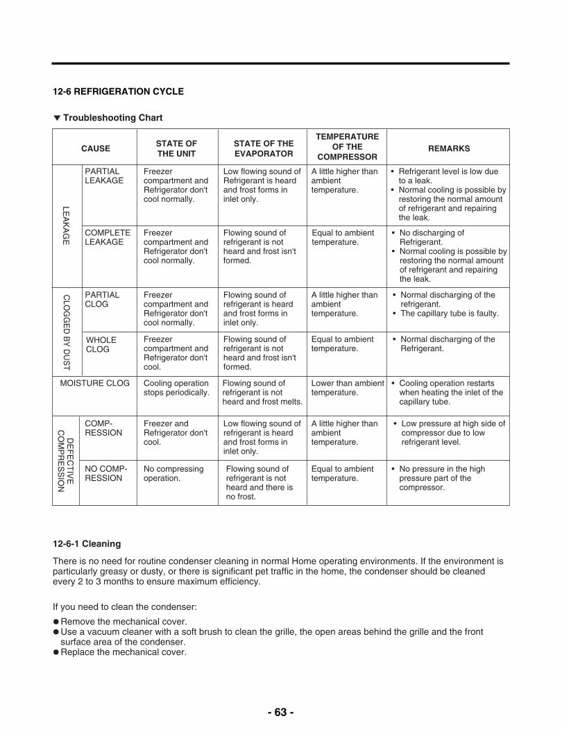
12-6 REFRIGERATION CYCLE
Troubleshooting Chart
PARTIALLEAKAGE
Freezercompartment andRefrigerator don'tcool normally.
Low flowing sound ofRefrigerant is heardand frost forms ininlet only.
A little higher thanambienttemperature.
• Refrigerant level is low dueto a leak.
• Normal cooling is possible byrestoring the normal amountof refrigerant and repairingthe leak.
COMPLETELEAKAGE
Freezercompartment andRefrigerator don'tcool normally.
Flowing sound ofrefrigerant is notheard and frost isn'tformed.
Equal to ambienttemperature.
• No discharging ofRefrigerant.
• Normal cooling is possible byrestoring the normal amountof refrigerant and repairingthe leak.
LEA
KA
GE
PARTIALCLOG
Freezercompartment andRefrigerator don'tcool normally.
Flowing sound ofrefrigerant is heardand frost forms ininlet only.
A little higher thanambienttemperature.
• Normal discharging of therefrigerant.
• The capillary tube is faulty.
WHOLECLOG
Freezercompartment andRefrigerator don'tcool.
Flowing sound ofrefrigerant is notheard and frost isn'tformed.
Equal to ambienttemperature.
• Normal discharging of theRefrigerant.
MOISTURE CLOG Cooling operationstops periodically.
Flowing sound ofrefrigerant is notheard and frost melts.
Lower than ambienttemperature.
• Cooling operation restartswhen heating the inlet of thecapillary tube.
CLO
GG
ED
BY
DU
ST
COMP-RESSION
Freezer andRefrigerator don'tcool.
Low flowing sound ofrefrigerant is heardand frost forms ininlet only.
A little higher thanambienttemperature.
• Low pressure at high side ofcompressor due to lowrefrigerant level.
NO COMP-RESSION
No compressingoperation.
Flowing sound ofrefrigerant is notheard and there isno frost.
Equal to ambienttemperature.
• No pressure in the highpressure part of thecompressor.
DE
FE
CT
IVE
CO
MP
RE
SS
ION
CAUSE REMARKSSTATE OF THEEVAPORATOR
TEMPERATUREOF THE
COMPRESSOR
STATE OFTHE UNIT
12-6-1 Cleaning
There is no need for routine condenser cleaning in normal Home operating environments. If the environment isparticularly greasy or dusty, or there is significant pet traffic in the home, the condenser should be cleanedevery 2 to 3 months to ensure maximum efficiency.
If you need to clean the condenser:
Remove the mechanical cover.Use a vacuum cleaner with a soft brush to clean the grille, the open areas behind the grille and the front
surface area of the condenser.Replace the mechanical cover.
- 64 -
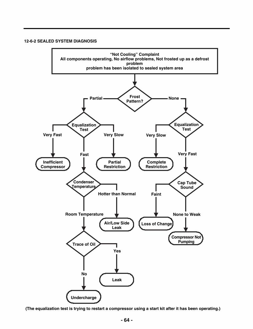
12-6-2 SEALED SYSTEM DIAGNOSIS
“Not Cooling” ComplaintAll components operating, No airflow problems, Not frosted up as a defrost
problemproblem has been isolated to sealed system area
FrostPattern?
Partial
EqualizationTest
Very Slow
None
EqualizationTest
Very FastFast
Very Fast
InefficientCompressor
PartialRestriction
CompleteRestriction
CondenserTemperature
Cap TubeSound
Yes
No
Air/Low SideLeak
Loss of Change
Very Slow
FaintHotter than Normal
None to WeakRoom Temperature
Compressor NotPumping
Trace of Oil
Undercharge
(The equalization test is trying to restart a compressor using a start kit after it has been operating.)
Leak
- 65 -
13. ICEMAKER OPERATING METHOD AND TROUBLE SHOOTING
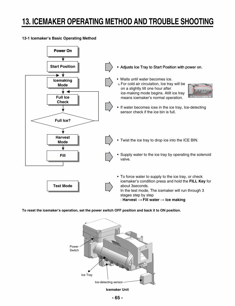
13-1 Icemaker’s Basic Operating Method
Power OnPower On
Start Position • Adjusts Ice Tray to Start Position with power on.• Adjusts Ice Tray to Start Position with power on.
IcemakingMode
Full IceCheck
HarvestMode
Full Ice?
Fill
Test Mode
• If water becomes ices in the ice tray, Ice-detectingsensor check if the ice bin is full.
• Twist the ice tray to drop ice into the ICE BIN.
• Supply water to the ice tray by operating the solenoidvalve.
• To force water to supply to the ice tray, or checkicemaker’s condition press and hold the FILL Key forabout 3seconds. In the test mode, The icemaker will run through 3stages step by step: Harvest Fill water Ice making
To reset the icemaker’s operation, set the power switch OFF position and back it to ON position.
Icemaker Unit
PowerSwitch
Ice Tray
Ice-detecting sensor
• Waits until water becomes ice.For cold air circulation, Ice tray will be on a slightly tilt one hour after ice-making mode begins. Atilt ice tray means icemaker’s normal operation. Ice Tray on a slightly tilt

- 66 -
13-2 ICE MAKER FUNCTIONS
13-2-1 Icemaking Mode
1. Icemaking Mode begins right after the ice tray fills with water.2. Icemaker waits until water becomes ice in the ice tray.
Ice-detecting sensor checks if the ice bin is full every 2min.
13-2-2 Harvest Mode
At least in 110min, since icemaker begun icemaking mode, Icemaker starts to twist the ice tray to drop ices into the Ice bin.(After installation, at least 1day is needed to make ices)
If the icemaker never drop ices to the ice bin though water becomes ices in the ice tray, check the real temperature ofcompartment. (not temperature on display) Icemaker needs below 0°F to drop ices to ice bin.
13-3 Trouble Shooting Ice & Water system Issues
13-3-1 Icemaker not making ice or not making enough ice (Environmental Diagnosis)
Icemaker can’t make ices itself. Basically, water, temperature and time are needed.- Water : If no Water, then no Ice.- Temperature : The compartment, where the icemaker is located, has to be at least 1°F so that icemaker dumps ices to
the bin.- Time : At least 80 minutes must be passed to make one series of ices after water comes into icemaker.
Test Mode should not be carried out before checking below.
13-2-3 Fill/Park Position
Once the normal harvest mode has been completed, the water solenoid will be activated.
Not making ice
Water
Yes
Yes
No
No
No
Temperature
Time
Is Icemaker’s tray filledwith water or Ice?
Is measuredtemperature below 10°Fin the icemakercompartment
How long has customerwaited for icemaker tomake ices?
1. Is saddle valve turned on? Check saddle valve.2. Is the icemaker fill tube frozen? Check the fill tube heater’s electrical
resistance.3. Are water valve housings are connected properly? Check all the water valve’
connection.4. Water line kinked or damaged? 5. Is water filter too old?
1. Does cold air come out from air vent normally? Check if Icing fan is working.Check if multi duct is blocked.
2. Are the R & F room cold enough? Measure the temp. and Check gas leakageat the back.
3. Does icemaker compartment door close tightly?
1. At least 120min. must be passed to make ices after water comes into icemaker.2. At least 24 hours must be passed to have ice bin full of ices. (not in case of
installation)
If the issue haven’t resolved yet, though you have checked all the items above, go to next step.

- 67 -
13-3-2 Icemaker not making ice or not making enough ice (Icemaker Unit & Ice-detecting sensor Diagnosis)
Icemaker Unit and Ice-detecting sensor DiagnosisThe icemaker unit and Ice-detecting sensor is programmed to be diagnosed. Follow the procedure step by step to check to see if icemaker and Ice-detecting sensor is working normally.
1st STEP (Icemaker Unit Diagnosis)Press the fill key for about 3sec. If the icemaker runs 2 stages of harvest and filling water step by step, It means icemaker’smechanism is normal.
Caution : Be sure that the ice tray is not filled with water before pressing fill key.
Icemaker Unit
Fill Key
Ice-detecting sensor

- 68 -
13-3-3 Icemaker not making ice or not making enough ice (Other Suspected Items)
Strongly suspect items below If the issue remains yet, though all the diagnosis for icemaker has been carried out.- Cap duct bad sealing - Defective thermal sensor in the icemaker compartment - Not cold icemaker compartment area (sealed system)
13-3-4 Not Dispensing Ice
Clogged Ice In the Ice Bin (suspected items)- Customer haven’t used ice dispenser over a week.
Resolution : the ices gets stuck if customer doesn’t use ice dispenser. In this case, empty the ice bin and wait until the new ices are stacked in the ice bin.
- Temperature of icemaker compartment is not cold enough. Resolution : Check ice fan, sealed system, cap duct, vent and other items related to temperature.
- Cap duct doesn’t seal the air properly.Resolution : Possibly, warm air could get into the compartment and make ices get stuck. Replace the cap duct withnew one.
- In-door geared motor doesn’t workResolution : Change the in-door geared motor and test it.
- The water comes out of fill cup and the water get into the ice bin.Resolution : The water pressure from shutoff valve is too high. Recommend to use regulator to the customer and close the shutoff valve slightly.
Clogged Ices In the Chute (suspected items)- Cap duct doesn’t seal the air properly.
Resolution : Possibly, warm air could get into the compartment and make ices get stuck. Replace the cap duct withnew one.
2st STEP (Ice-detecting sensor Diagnosis)
3. Wait for 3min.1. Remove Ice bin from compartment
4. Freezer door stays open
5. Push the refrigeratorbutton & lock button at the
same time.
2. Close the left door(Door switch pushed)
If ETY is shown on the display after the procedure above, Ice-detecting sensor is normal. If FULL is shown on the display after the procedure above, Ice-detecting sensor is abnormal.
ETY = empty
- 69 -
14. DESCRIPTION OF FUNCTION & CIRCUIT OF MICOM
14-1 FUNCTION
14-1-1 Function
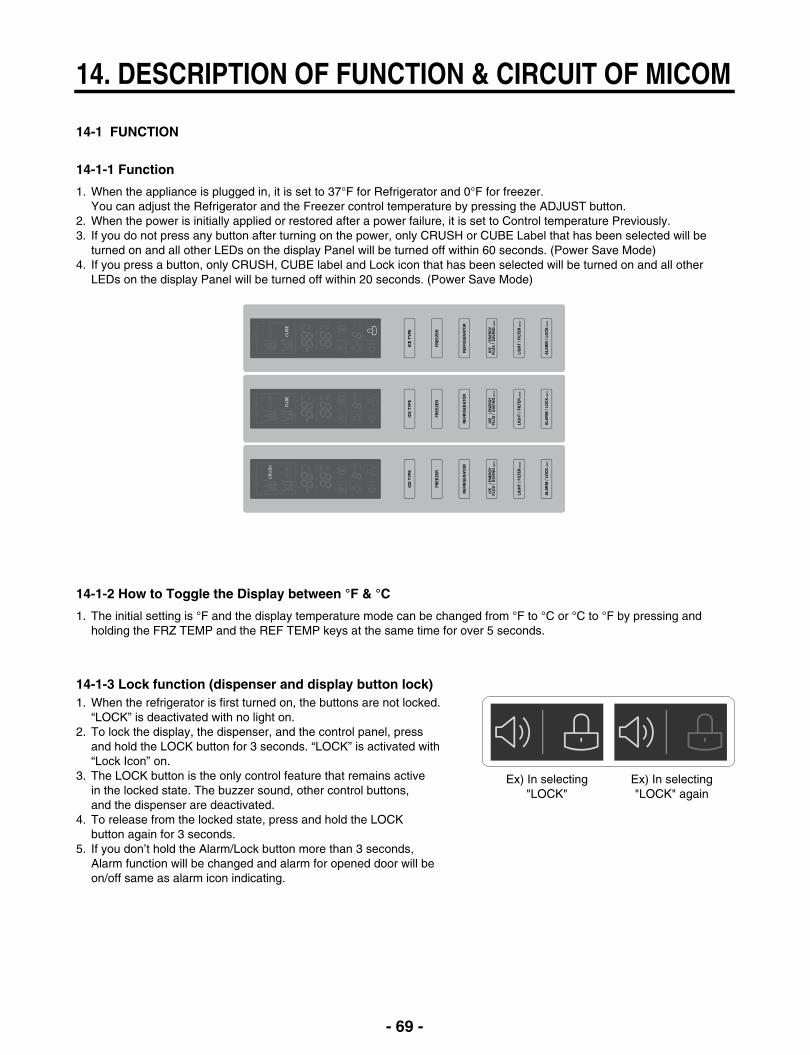
1. When the appliance is plugged in, it is set to 37°F for Refrigerator and 0°F for freezer.You can adjust the Refrigerator and the Freezer control temperature by pressing the ADJUST button.
2. When the power is initially applied or restored after a power failure, it is set to Control temperature Previously.3. If you do not press any button after turning on the power, only CRUSH or CUBE Label that has been selected will be
turned on and all other LEDs on the display Panel will be turned off within 60 seconds. (Power Save Mode) 4. If you press a button, only CRUSH, CUBE label and Lock icon that has been selected will be turned on and all other
LEDs on the display Panel will be turned off within 20 seconds. (Power Save Mode)
14-1-2 How to Toggle the Display between °F & °C
1. The initial setting is °F and the display temperature mode can be changed from °F to °C or °C to °F by pressing andholding the FRZ TEMP and the REF TEMP keys at the same time for over 5 seconds.
14-1-3 Lock function (dispenser and display button lock)1. When the refrigerator is first turned on, the buttons are not locked.
“LOCK” is deactivated with no light on.2. To lock the display, the dispenser, and the control panel, press
and hold the LOCK button for 3 seconds. “LOCK” is activated with“Lock Icon” on.
3. The LOCK button is the only control feature that remains activein the locked state. The buzzer sound, other control buttons,and the dispenser are deactivated.
4. To release from the locked state, press and hold the LOCKbutton again for 3 seconds.
5. If you don’t hold the Alarm/Lock button more than 3 seconds,Alarm function will be changed and alarm for opened door will beon/off same as alarm icon indicating.
Ex) In selecting"LOCK"
Ex) In selecting"LOCK" again

- 70 -
14-1-4 Filter condition display function
1. There is a replacement indicator light for the filtercartridge on the dispenser.
2. Water filter needs replacement once six months or ofusing water filter.
3. When the Water Filter Icon blinks, you must exchangethe filter.
4. After replacing the filter, press and hold the Light/Filterbutton for more than 3 seconds.After then water Filter icon turn off with reset status.
In initial Power On/ Filter RESET
Blinking
Filter StatusDisplay
Classification
14-1-5 Ice Plus selection
1. Please select ice plus function for quick freezing.2. When you press the ice plus button, the ice plus icon will be turned
on again.3. Ice plus function automatically turns off after a fixed time passes.4. If you want additional power save, you can turn on energy saving
(some heater off for anti-dew). 5. To turn on or off the energy saving function, press Ice plus/Energy
saving Button for more than 3 seconds.6. We recommend using energy saving function when you go out for
quite a long time and are out of the rainy season.
14-1-6 Dispenser use selection
You can select water or ice by separated pad switch.
• When you press ice type button, ice type will be changed. (Crush orCube)
• Hold your cup in the dispenser for a few seconds after dispensingice or water to allow the last pieces of ice drops of water to fall intothe cup.
• When after initially establ ishing the water comes out, the water tankinside fills and until at the time of quality the hour is caught.
WATER PADICE PAD

- 71 -
14-1-11 Ice PLUS
1. The purpose of this function is to intensify the cooling speed of freezer and to increase the amount of ice.2. Whenever selection switch is pressed, selection/release, the Icon will turn ON or OFF.3. If there is a power outage and the refrigerator is powered on again, Ice PLUS will be canceled.4. To activate this function, press the Ice PLUS key and the Icon will turn ON. This function will remain activated for 24 hrs.
The first one hour the compressor, Freezer Fan and Icing Fan will be ON. The next 23 hours the Ice room will becontrolled at the lowest temperature. After 24 hours or if the Ice PLUS key is pressed again, the Ice room will return to itsprevious temperature.
5. During the first hour :(1) Compressor, Freezer Fan and Icing Fan run continuously.(2) If a defrost cycle begins during the first 30 minutes of Ice Plus, the Ice PLUS cycle will complete its cycle after
defrosting has ended.If the defrost cycle begins when Ice Plus has run for more than 30 minutes, Ice PLUS will run for 40 minutes after thedefrost is completed.
(3) If Ice PLUS is pressed during defrost, Ice Plus Icon is on but this function will start seven minutes after defrost iscompleted and it shall operate for three hours.
(4) If Ice Plus is selected within seven minutes after compressor has stopped, the compressor (compressor delays seven minutes) shall start after the balance of the delay time.
6. For the rest of the 23 hours, the Ice room will be controlled at the lowest temperature.
14-1-12 How to set the display mode and cancel it
1. With the refrigerator door open, keep pressing the Refrigerator Temp Button and ICE PLUS Button more than 5 seconds,then it goes to the display mode with Special Beep Sound With Special Beep Sound.
2. Perform the same way again to cancel the display mode.3. All Freezing unit will be turned off at display mode (Exceptions : Lamp, Display)
14-1-7 CONTROL OF FREEZER FAN MOTOR
1. Freezer fan motor has high and standard speeds.2. High speed is used at power-up, for Ultra Ice, and when refrigerator is overloaded.
Standard speeds is used for general purposes.3. To improve cooling speed, the RPM of the freezer fan motor change from normal speed to high.4. High speed (2700RPM) : Initial power on or load corresponding operation, Ultra Ice.
Normal speed (2400RPM) : General working conditions.
14-1-8 Cooling Fan Motor
1. The cooling fan is switched ON and OFF in conjunction with the compressor.2. The cooling fan Motor has high and standard speeds. (When room temper rapture more high then 38°C speed is high)3. The Failure sensing method is the same as in the fan motor of the freezing fan motor(refer to failure diagnosis function
table for failure display).
14-1-9 Ice Compartment Fan
1. The Icing Fan is controlled by the the sensor on the top of the ice compartment.2. The Failure sensing method is the same as in the fan motor of the freezer
(refer to failure diagnosis function table for failure display)
14-1-10 Refrigeration room Fan Motor
1. The refrigeration room fan is switched ON and OFF in conjunction with the refrigeration room temperature.2. The Failure sensing method is the same as in the fan motor of the freezing fan motor (refer to failure diagnosis function
table for failure display).
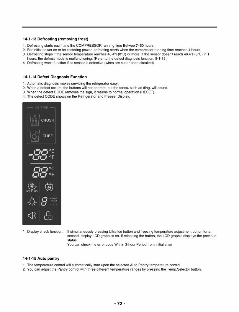
- 72 -
14-1-13 Defrosting (removing frost)
1. Defrosting starts each time the COMPRESSOR running time Betwee 7~50 hours.2. For initial power on or for restoring power, defrosting starts when the compressor running time reaches 4 hours.3. Defrosting stops if the sensor temperature reaches 46.4°F(8°C) or more. If the sensor doesn’t reach 46.4°F(8°C) in 1
hours, the defrost mode is malfunctioning. (Refer to the defect diagnosis function, 8-1-15.)4. Defrosting won’t function if its sensor is defective (wires are cut or short circuited)
14-1-15 Auto pantry
1. The temperature control will automatically start upon the selected Auto Pantry temperature control.2. You can adjust the Pantry control with three different temperature ranges by pressing the Temp.Selector button.
14-1-14 Defect Diagnosis Function
1. Automatic diagnosis makes servicing the refrigerator easy.2. When a defect occurs, the buttons will not operate; but the tones. such as ding. will sound.3. When the defect CODE removes the sign, it returns to normal operation (RESET).4. The defect CODE shows on the Refrigerator and Freezer Display.
* Display check function: If simultaneously pressing Ultra Ice button and freezing temperature adjustment button for a second, display LCD graphics on. If releasing the button, the LCD graphic displays the previous status.You can check the error code Within 3-hour Period from initial error

15. EXPLODED VIEW & REPLACEMENT PARTS LIST
406D
402A
271B
500P
103B
103A
501F
503D
503E
610D
207A
624A
624C
624G
626A
603C
603E624E
207B402A
120A
120C
145A
405E329B
405C405F
120F 120B
500A
410J271D
S01
S01
B01
B01
S03
S03
282G
158A
405D
404B405H
405I282F
145B
262B
406B
405J
315B315C
323B
319A
319C
420A
S20
315B
158B
409B
503G
409D
405H
405B329A
332C
405C
405F
407A
103C
315A
315C
106A
106A
313A
410G411A
249C
262H
249D
310B
312A
300A314A
317A318A
309B 329C
312C
303A
304A303C
302B
400A
408A
404A
105A105D
146G
CASE PARTSCAUTION: Use the part number to order part, not the position number.
610E

133B
131A
133B
145F
136A
133A
132P
237C
133B
136B
145C
136C
FREEZER PARTSCAUTION: Use the part number to order part, not the position number.
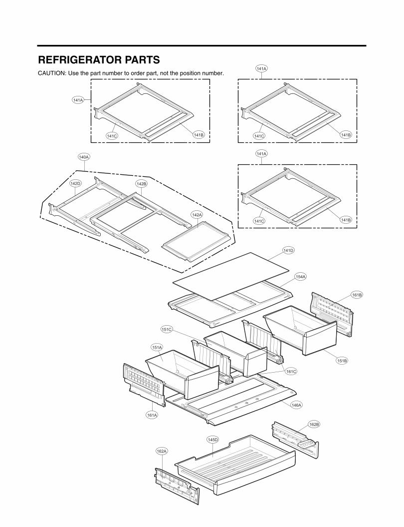
161C
151A
146A
151B
140A
142D 142B
141A
141C 141B
141A
141C 141B
141A
141C 141B
142A
161B
141D
154A
162B
145D
162A
161A
151C
REFRIGERATOR PARTSCAUTION: Use the part number to order part, not the position number.
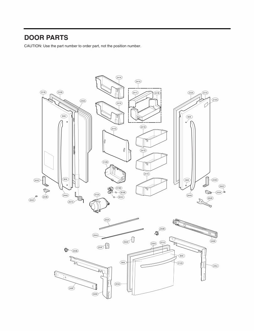
233A 231A
212G
B06
233B231B
235A
B06
B06243C
244A243B
241G241D
241D
241E
B06 243D
243A
262E
244A
241C
241A
241B
203A
B06
250F
250K
212D
B06
619B
603B
603C
200A
262C
262C
249K
250A
253A
249J
250B
249F
250B
249E
615A
312B
241K
241K
201A
267A
DOOR PARTSCAUTION: Use the part number to order part, not the position number.
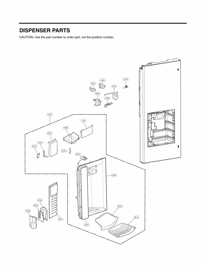
279B
276A
276B
405A
279I
279H
279J
402C
281A
279D
500C
279E
501A
279A
279C
281B
275A
276F
276G
501D
278C
278D
DISPENSER PARTSCAUTION: Use the part number to order part, not the position number.

617A
625A
616G
623B
616J
616G
623B616J
603C
616D
616D
616F
627B
619E
627A
603B
619A
VALVE & WATER TUBE PARTSCAUTION: Use the part number to order part, not the position number.
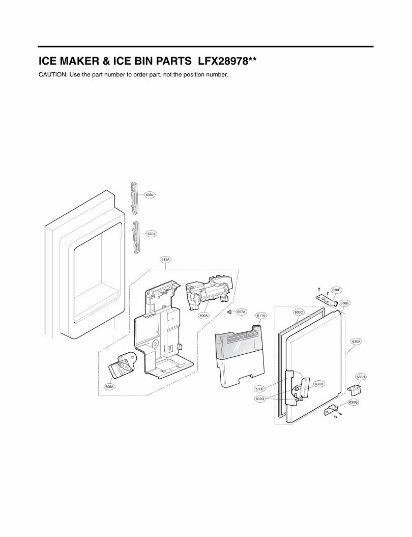
ICE MAKER & ICE BIN PARTS LFX28978**CAUTION: Use the part number to order part, not the position number.
600A
630F
630B
630A
630H
630G
630C
630Q
630E
630D
611A
612A
630J
606A
630J
607A

China ni detnirP 2102 .YAM