Embed Size (px)
Citation preview
17
www.truemfg.comTRUETECHNICAL SERVICE MANUAL - ALL MODELS
In this section you can find information that is helpful for the
customer and the service technician to help you understand how
our refrigeration system works along with how to diagnose
and correct any problems that might arise.
REFRIGERATION

NOTES
18

www.truemfg.com
19
TRUETECHNICAL SERVICE MANUAL - ALL MODELS
Basics
REFRIGERATION

Good refrigeration practices will always start with good detective work to find out what caused the failure so we can eliminate the possibility of a repeat failure. Below is a step by step set of procedures we would recommend is followed when repairing a refrigeration system.
ANY NITROGEN ADDED TO THE SYSTEM SHOULD NOT EXCEED 200 PSI.
Before opening the refrigeration system remember that POE oil is very hydroscopic and absorbs moisture very quickly. You should not leave the system open to the atmosphere for more that 15 minutes. Any vacuum that exists before any repair should be broken with nitrogen to avoid moisture being pulled into the system. ALWAYS CHANGE THE DRIER WHENEVER THE REFRIGERATION SYSTEM HAS BEEN OPENED.
Recover the refrigerant from the system.
The introduction to the refrigeration system of anything other than a flushing agent, nitrogen, refrigerant, or oil is prohibited.
Remove the faulty refrigeration component and filter drier by cutting them out with a tubing cutter. (We would recommend this method over removing with a torch since it may destroy the evidence of what may have caused the failure or signs of oil contamination.)
If you are changing a component keep the system closed up with plugs or caps to reduce moisture contamination.
Take a look at the filter drier and the components that have been removed for signs of oil breakdown, foreign objects like desiccant from drier, metal pieces from valves, etc.
When replacing a compressor make sure to also remove all old oil from the system.
Be sure to pierce a hole (approx 1/8”) in the bottom of the accumulator so we do not leave contaminated oil in the system. After blowing this out with nitrogen, be sure to braze the hole closed.
Be sure and test the oil from the refrigeration system for contamination using the proper test kit for the type of oil.
If the oil shows signs of contamination or there was a restriction in the system, all of the oil must be removed and replaced. This can be done by flushing the entire system with nitrogen, removing all the oil in the compressor, and in the accumulator, measure all of the old oil in a measuring cup and replace the exact amount you removed with the new oil.
Now that the system has been cleaned up, install the new compressor. Please also remember that the system should not be opened more than 15 minutes.
Now place a nitrogen charge in the system to check for any leaks. Use maximum 200 PSI.
Release the nitrogen charge down to about 2 pounds of positive pressure.
Start pulling a vacuum as soon as possible to help remove any moisture from the system. Remember that any moisture that is absorbed by the POE oil cannot be removed and we must start the process over.
Change vacuum pump oil regularly to ensure the deepest vacuum your pump is capable of.
Using a micron gauge, pull the system down to hold a minimum of 500 microns.
See if the system will hold this micron with the gauges closed and the pump switched off to test for leaks or moisture.
Once the system is evacuated, weigh in the proper charge as a liquid only on the high side of the refrigeration system.
Test run the unit and check for proper operation.
RD 6/14
Good Refrigeration PracticesBUILDING THE FINEST COMMERCIAL REFRIGERATION-TRUE, “The Best of the Cold Ones”
Manufacturing
1 855 372 [email protected]
UK+44 1709 888 0808:30AM – 5:00PM M-F
GERMANY+49 7622 667 71058:00AM – 5:00PM M-F
AUSTRALIA+61 2 9218 45008:30AM – 5:00PM M-F
MEXICO CITY+52 555 804 6343/449:00AM – 5:30PM M-F
PLEASE CALL TRUE TECHNICAL SERVICE WITH ANY QUESTIONS REGARDING THE ABOVE PRACTICES.
WORLD HEADQUARTERS: O’FALLON, MISSOURI, USASERVICE DEPARTMENT HOURS OF OPERATION: 7:00-7:00 CST MONDAY-THURSDAY, 7:00-6:00 FRIDAY, 8:00-12:00 SATURDAYS
TRUETECHNICAL SERVICE MANUAL - ALL MODELS www.truemfg.com
21
GOOD REFRIGERATION PRACTICES
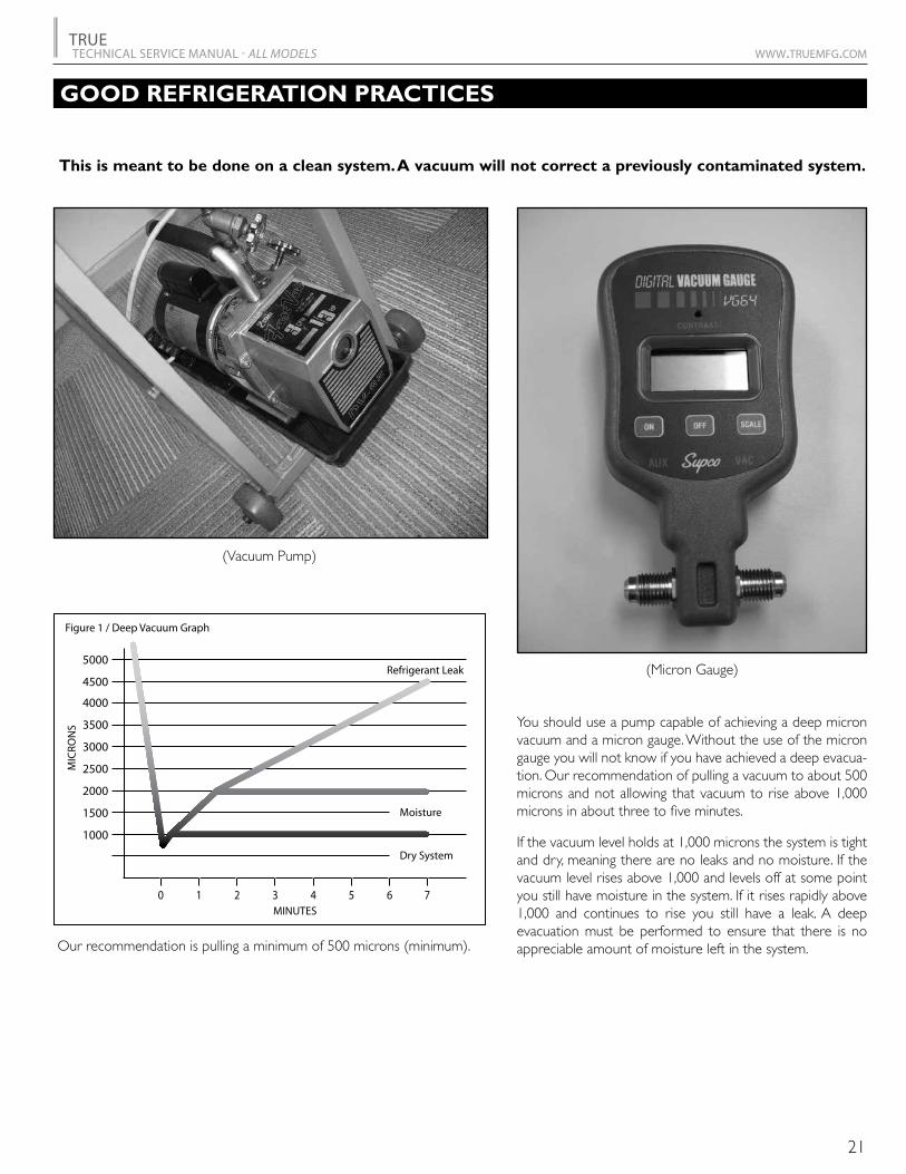
(Vacuum Pump)
(Micron Gauge)
0 1 2 3 4 5 6
1000
1500
2000
2500
3000
3500
4000
4500
5000
7
Figure 1 / Deep Vacuum Graph
Dry System
MINUTES
Moisture
Refrigerant Leak
MIC
RON
S You should use a pump capable of achieving a deep micron vacuum and a micron gauge. Without the use of the micron gauge you will not know if you have achieved a deep evacua-tion. Our recommendation of pulling a vacuum to about 500 microns and not allowing that vacuum to rise above 1,000 microns in about three to five minutes.
If the vacuum level holds at 1,000 microns the system is tight and dry, meaning there are no leaks and no moisture. If the vacuum level rises above 1,000 and levels off at some point you still have moisture in the system. If it rises rapidly above 1,000 and continues to rise you still have a leak. A deep evacuation must be performed to ensure that there is no appreciable amount of moisture left in the system.
This is meant to be done on a clean system. A vacuum will not correct a previously contaminated system.
Our recommendation is pulling a minimum of 500 microns (minimum).
TRUETECHNICAL SERVICE MANUAL - ALL MODELS www.truemfg.com
22
GOOD REFRIGERATION PRACTICES
OPERATION INSTRUCTIONS
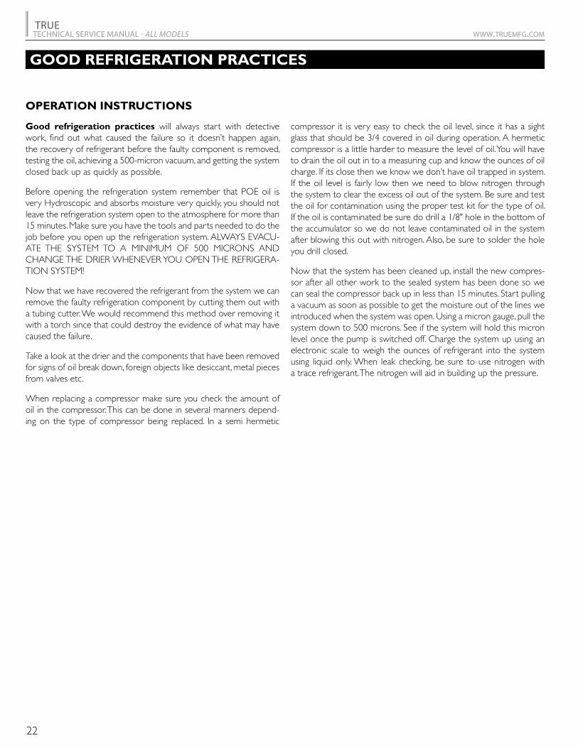
Good refrigeration practices will always start with detective work, find out what caused the failure so it doesn’t happen again, the recovery of refrigerant before the faulty component is removed, testing the oil, achieving a 500-micron vacuum, and getting the system closed back up as quickly as possible.
Before opening the refrigeration system remember that POE oil is very Hydroscopic and absorbs moisture very quickly, you should not leave the refrigeration system open to the atmosphere for more than 15 minutes. Make sure you have the tools and parts needed to do the job before you open up the refrigeration system. ALWAYS EVACU-ATE THE SYSTEM TO A MINIMUM OF 500 MICRONS AND CHANGE THE DRIER WHENEVER YOU OPEN THE REFRIGERA-TION SYSTEM!
Now that we have recovered the refrigerant from the system we can remove the faulty refrigeration component by cutting them out with a tubing cutter. We would recommend this method over removing it with a torch since that could destroy the evidence of what may have caused the failure.
Take a look at the drier and the components that have been removed for signs of oil break down, foreign objects like desiccant, metal pieces from valves etc.
When replacing a compressor make sure you check the amount of oil in the compressor. This can be done in several manners depend-ing on the type of compressor being replaced. In a semi hermetic
compressor it is very easy to check the oil level, since it has a sight glass that should be 3/4 covered in oil during operation. A hermetic compressor is a little harder to measure the level of oil. You will have to drain the oil out in to a measuring cup and know the ounces of oil charge. If its close then we know we don’t have oil trapped in system. If the oil level is fairly low then we need to blow nitrogen through the system to clear the excess oil out of the system. Be sure and test the oil for contamination using the proper test kit for the type of oil. If the oil is contaminated be sure do drill a 1/8" hole in the bottom of the accumulator so we do not leave contaminated oil in the system after blowing this out with nitrogen. Also, be sure to solder the hole you drill closed.
Now that the system has been cleaned up, install the new compres-sor after all other work to the sealed system has been done so we can seal the compressor back up in less than 15 minutes. Start pulling a vacuum as soon as possible to get the moisture out of the lines we introduced when the system was open. Using a micron gauge, pull the system down to 500 microns. See if the system will hold this micron level once the pump is switched off. Charge the system up using an electronic scale to weigh the ounces of refrigerant into the system using liquid only. When leak checking, be sure to use nitrogen with a trace refrigerant. The nitrogen will aid in building up the pressure.

TRUETECHNICAL SERVICE MANUAL - ALL MODELS www.truemfg.com
23
POLYOL ESTER LUBRICANT
After exhaustive research and testing, Copeland has determined that Polyol Ester (POE) lubricants provide the best combination of characteristics for use with the new generation of chlorine-free re-frigerant. In addition to providing superior lubrication. POE has other advantages which increase its attractiveness for use in refrigeration.
Polyol Ester is a synthetic lubricant used primarily for jet engine lu-brication. It is manufactured by numerous companies and there are various types and grades available. Therefore, it is important to recog-nize that all POE’s are not the same.
Since POE is synthetic, it has better resistance to high temperature degradation than refrigeration mineral oils. POE is also made from more expensive base stocks making it significantly more expensive than other refrigeration oils. Furthermore, POE is compatible with common refrigerant and mineral oil. Therefore, a compressor con-taining the oil can be installed in a system containing HCFC’s or HFC’s. In short, POE provides significant flexibility in the face of changes brought on by the CFC issue.
HFC refrigerant require the use of POE for all Copeland compres-sors. This is necessary for two specific reasons. First, mineral oils are not readily miscible in HFC’s. When using HFC’s conventional oils will not return to the compressor. Secondly, the chlorine contained in CFCs and HCFCs aids in the lubricity of mineral oil.
One drawback from using POE is that they absorb moisture from the air at a much greater rate than do mineral oils. As a result, they must be handled and packaged with much more care than conventional oils. Copeland has not tested all types of compressors or all combina-tions of refrigerant and con-Industry knowledge of POE must rapidly increase in order to maintain and improve expected reliability.
After conducting extensive tests for both compressor durability and reliability on more than 40 refrigerant/oil combinations, Copeland identified Mobil Oil Corporation as our preferred U.S. supplier of polyol ester oil in terms of both the oil itself and Mobil’s ability to package and deliver the oil with acceptable low moisture levels. Be-cause of its technical superiority. Copeland has approved Mobil’s EAL Artic 22 CC polyol ester oil for use in our compressors.
To serve our customers, Copeland will distribute EAL Artic 22 CC to the after market through Copeland’s network of 800 authorized wholesalers. The lubricant will be charged into our new production compressors whenever a polyol ester is specified. Currently, certain approved compressor models sold to OEMs are available with this oil installed during manufacture. Refrigeration service compressors charged with POE will be supplied in the near future.
THE CFC REPORT - LEADING THE WAY INTO A NEW AGE
SERVICE CONTRACTORS (ATTENTION PLEASE)
SERVICE CONTRACTORS
ATTENTION PLEASE
This is a Tecumseh hermetic compressor specifically designed for use with environmentally friendly HFC refrigerant R404A. However, it is ac-ceptable to use this compressor as a service replacement with R502.
The Tecumseh approved polyolester (POE) oil contained in this compressor is compatible with all internal component materials and is miscible (mixes) with R502 to effect proper oil return. Using R502 with this R404A compressor will result in very similar performance to the replaced R502 compressor. But, the following precautions should be taken.
1. Care must be taken to assure that most of the mineral oil is removed from the system before the new com-pressor is installed. Small amounts of mineral oil (up to 5%) left in the system are acceptable but 1% or less if achievable is desired.
2. POE oils are 100 times more hygroscopic (ability to absorb moisture) than mineral oils thus the utmost care must be taken to prevent moisture from entering the
system. The compressor or system should not be left open to the atmosphere for longer than 15 minutes maximum.
3. The appropriate new drier provided must be installed in the system.
4. Established industry procedures for recovery, evacu-ation, refrigerant charging and leak testing should be followed.
TRUE MANUFACTURING COMPANY

TRUETECHNICAL SERVICE MANUAL - ALL MODELS www.truemfg.com
24
CAPILLARY TUBE SYSTEM
REFRIGERATION BASICS
THE CAPILLARY TUBE SYSTEM
Starting at the Capillary Tube, refrigerant flows into the evaporator and changes from a liquid to a gas. As it absorbs heat, after leaving the evaporator, it flows through the accumulator. The accumulator is a part that is designed like a reservoir to allow any refrigerant, that has not changed from a liquid to a gas, space to do so before returning to the compressor. After flowing through the accumulator, refrigerant flows through the suction line as a low pressure gas into the com-pressor. The compressor pumps the refrigerant from a low pressure gas to a high pressure gas and forces it into the condenser. In the con-denser with a fan circulating air over it the refrigerant condenses from high pressure gas to high pressure liquid. After leaving the condenser
refrigerant flow through the drier which is designed to remove any particles or moisture in the system. Refrigerant then flows through the liquid line into the capillary tube. The capillary tube is designed to allow a certain amount of refrigerant to flow through it to keep the evaporator evenly flooded. The capillary tube is taped to the suc-tion line to cool the liquid to allow the best heat transfer. When the refrigerant enters the evaporator as a liquid, warm air from inside the cabinet is circulated through the evaporator coil and the heat from the air is then absorbed in the refrigerant.

www.truemfg.com
25
CAPILLARY TUBE SYSTEM
Suc
tion
Line
(lo
w p
ress
ure
vapo
r)
Cap
illar
y Tu
be (
liqui
d lin
e)
Eva
pora
tor
Dra
in T
ube
Hot air out
Cool air in
Evaporator Fan Motor
The Refrigeration Cycle
Low pressure liquid
High pressure liquid
High pressure vapor
Low pressure vapor
Evaporator
1
2
3
4
5
6
2. Compressor
Condenser
Capillary Tube
5. Thermostat
Condensate Pan
Color ChartThe condensate pan collects moisture that has condensed on the outside of the evaporator coil and drained through the evaporator drain tube. Warm air from the condenser coil is utilized to evaporate the water in the condensate pan.
The thermostat senses the evaporator temperature; cycling the compressor on and off.
The capillary tube meters the volume of high pressure liquid refrigerant entering the evaporator coil.
While the condenser fan motor(s) circulate cool ambient air over the condenser coil; heat absorbed by the refrigerant in the evaporator coil is removed. This causes a change of state in the refrigerant from a high pressure vapor to a high pressure liquid.
Low pressure vapor refrigerant is compressed, combining the heat absorbed in the evaporator with the heat of compression from the piston stroke before being pumped into the condenser.
While the evaporator fan motor(s) circulate air over the evaporator coil; liquid refrigerant running within the evaporator coil tubing absorbs heat through the walls of the evaporator coil. This causes a change of state in the refrigerant from a low pressure liquid to a low pressure vapor.
1
2
3
4
5
6
Drier
SB • 3/14
TRUETECHNICAL SERVICE MANUAL - ALL MODELS www.truemfg.com
26
TRUE’S REMOTE SYSTEM - HOW IT WORKS
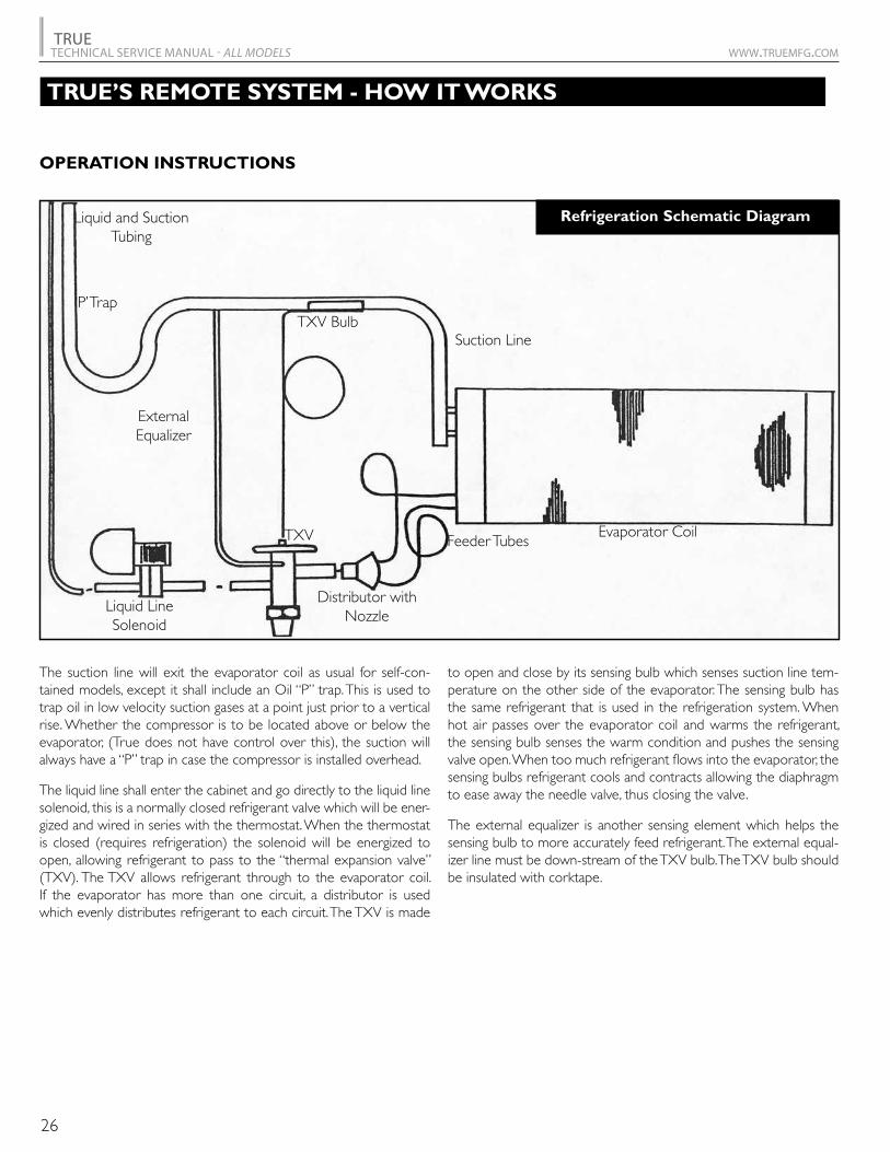
The suction line will exit the evaporator coil as usual for self-con-tained models, except it shall include an Oil “P” trap. This is used to trap oil in low velocity suction gases at a point just prior to a vertical rise. Whether the compressor is to be located above or below the evaporator, (True does not have control over this), the suction will always have a “P” trap in case the compressor is installed overhead.
The liquid line shall enter the cabinet and go directly to the liquid line solenoid, this is a normally closed refrigerant valve which will be ener-gized and wired in series with the thermostat. When the thermostat is closed (requires refrigeration) the solenoid will be energized to open, allowing refrigerant to pass to the “thermal expansion valve” (TXV). The TXV allows refrigerant through to the evaporator coil. If the evaporator has more than one circuit, a distributor is used which evenly distributes refrigerant to each circuit. The TXV is made
to open and close by its sensing bulb which senses suction line tem-perature on the other side of the evaporator. The sensing bulb has the same refrigerant that is used in the refrigeration system. When hot air passes over the evaporator coil and warms the refrigerant, the sensing bulb senses the warm condition and pushes the sensing valve open. When too much refrigerant flows into the evaporator, the sensing bulbs refrigerant cools and contracts allowing the diaphragm to ease away the needle valve, thus closing the valve.
The external equalizer is another sensing element which helps the sensing bulb to more accurately feed refrigerant. The external equal-izer line must be down-stream of the TXV bulb. The TXV bulb should be insulated with corktape.
Liquid and SuctionTubing
Suction Line
Evaporator Coil
Distributor with Nozzle
TXV Bulb
ExternalEqualizer
Liquid LineSolenoid
TXV Feeder Tubes
‘P’ Trap
OPERATION INSTRUCTIONS
Refrigeration Schematic Diagram

TRUETECHNICAL SERVICE MANUAL - ALL MODELS www.truemfg.com
27
BASIC REFRIGERATION
REFRIGERATION BASICS
CONTROL OF LIQUID REFRIGERANT FLOODBACK TO THE COMPRESSOR DURING OPERATION
Liquid refrigerant accumulation in the compressor can also be caused by liquid migration to the compressor during periods of shutdown. This condition can be controlled by the application of a crankcase heater. A suction line accumulator does nothing to prevent liquid migration and a crankcase heater does nothing to prevent liquid floodback. Each without the other is half a job - both together provide balanced compressor protection.
LOW PRESSUREGAS
HIGH PRESSUREGAS
LOW PRESSURELIQUID
HIGH PRESSURELIQUID
Fan Fan
Filter
Evaporator Condenser
Expansion Device
Compressor
Compressor
Fan Fan
Filter
Evaporator Condenser
Expansion Device
Accumulator
CrankcaseHeater
LOW PRESSUREGAS
HIGH PRESSUREGAS
LOW PRESSURELIQUID
HIGH PRESSURELIQUID
Liquid floodback during operation can be caused by fan failure, or dirty clogged filters that can reduce the heat transfer rate to such a point that the liquid refrigerant floods through, instead of vaporizing. When this situation occurs, liquid refrigerant may enter the compressor under conditions which result in separation of the oil and refrigerant. This separation may result in an accumula-tion of the refrigerant under the oil. Thus, when the compressor is started, the first liquid to be pumped to the bearings will probably be refrigerant, not oil. Even if this oil-refrigerant separation does not occur, the large amount of liquid refrigerant in the crankcase will instantly vaporize and boil away the oil charge when the compressor starts. Thereby leaving the compressor oil-starved for many seconds.
Liquid floodback can be prevented by the application of a properly designed and sized suction line accumulator. Using a totally new concept, Tecumseh en-gineers have designed a suction line accumulator available in eight basic sizes covering a full range of system applications and refrigerant. When properly se-lected based upon system charge, a Tecumseh suction line accumulator will improve compressor reliability and endurance by preventing damaging liquid refrigerant floodback.

TRUETECHNICAL SERVICE MANUAL - ALL MODELS www.truemfg.com
28
REFRIGERATION TROUBLESHOOTING
TROUBLESHOOTING INSTRUCTIONS // REFRIGERATION TROUBLESHOOTING CHART (REFRIGERATOR)
PROBLEM: Cabinet is running warm.
1. Are lights and evaporator fan working?
Check to make sure cabinet is plugged in, check to make sure circuit breaker is not tripped, check to see if tem-perature control is set on #5.
Remove the grill covering the condensing unit.
2. Is the condenser coil (looks like a car radiator) clean? If not clean this with a brush and either a vacuum or condensed air. Wait and let the cabinet run with a clean coil and see if that solves problem.
(CONDENSER COILS SHOULD BE CLEANED MONTHLY)
3. Can you hear the compressor and condenser fan motor running?
Check the voltage at the compressor receptacle. It should be 115 volts ±10%. Using a remote reading thermometer, check the evaporator coil temperature. If the tempera-ture control is set on #5 and the coil temperature is above 40 degrees the control should be closed calling for the compressor to run. If the coil temperature is above 40 degrees and the temperature control does not close.
1. remove the temperature control from the evaporator housing and either calibrate or replace control.
NOTE:
Some models use a temperature control relay.
Is the evaporator coil frozen? Check to see if tempera-ture control is operating correctly. If the evaporator coil is not iced up and the compressor and condenser fan is running, please install piercing valves on both the suction and discharge process tubes.
1. If pressures are equalized (high suction pressure, low head pressure) and compressor is running low amp draw, compressor has bad valves replace compressor.
2. If you have low suction pressure and low discharge pressure first check to make sure there are no kinks in the compressor pullout or the suction line after doing this you have a few options.
A. Add a few ounces of refrigerant and see what hap-pens.
B. Recover charge and weigh in correct amount of refrigerant.
If the pressures rose and the cabinet began to function correctly, the cabinet was low on charge. This means that there is a leak in the refrigeration system that must be located. A technician can raise system pressure up to 200 psi with nitrogen to aid in the leak search. (Remember that the foam insulation within the cabinet will make a leak detector sniffer type react.)
AFTER LEAK IS LOCATED IT IS VERY IMPORTANT THAT THE SYSTEM DRIER IS CHANGED AND THAT A 500 MICRON VACUUM IS PULLED THROUGH BOTH THE HIGH AND LOW SIDE ACCESS FITTINGS.
When leak is found, recover refrigerant. At this time the technician may want to remove piercing valves and solder on access valves to pull vacuum and recharge system. (Af-ter charging system both service valves should removed from the system.)
If the head pressure rises but falls right back down af-ter you stop adding gas and the suction pressure stays low there may be a restriction in the system. Recover the charge and cut out the drier also cut about 2" off of the capillary tube. Circulate nitrogen through the system to clear any restrictions in the evaporator. Evacuate the sys-tem and recharge.
If the problem still exists, capillary tube may need to be replaced.
NO
NO
YES
YES

TRUETECHNICAL SERVICE MANUAL - ALL MODELS www.truemfg.com
29
FREEZER TROUBLESHOOTING
TROUBLESHOOTING INSTRUCTIONS // REFRIGERATION TROUBLESHOOTING CHART (FREEZER)
PROBLEM: Cabinet is running warm.
1. Can you hear the compressor running?
If nothing is running and cabinet is warm check to make sure cabinet is plugged in and then check circuit breaker. On older GDM models the cabinet lights will not come on until the temperature reaches 20 degrees but on T-Series cabinets lights will work when you open the door at any temperature. All freezers have a fan delay that will not allow the evaporator fans to start before the fan delay/defrost termination switch is satisfied.
Remove the grill covering the condensing unit. Check the defrost timer to see if cabinet is in defrost. Do not turn dial on defrost timer, take a pencil and mark a spot on the outer dial and watch this to see if timer is working. This should take no more than 10 minutes to verify. While waiting, look to see if the condenser coil (looks like a car radiator) is clean. If coil is dirty clean with a brush and a vacuum or compressed air. (CONDENSER COILS SHOULD BE CLEANED MONTHLY)
If cabinet is not in defrost and the compressor and con-denser fan motor is not running, unplug the condensing unit and check the voltage at the compressor receptacle. The voltage should be within 10% on a 115 volt compres-sor and within 5% on a 208/230 volt compressor.
Any voltage less than that unplug cabinet and remove the temperature control from the evaporator housing and check out control. Control could be stuck open or be pitted due to low voltage or short cycling. Refer to Temperature Control section.
• There is a wiring diagram on the back of the electrical box cover plate. Use this to help you troubleshoot.
The compressor is running and cabinet is warm. Does the evaporator coil have an ice build up on it? If so follow above directions on how to verify if timer is advancing. If it is manu-ally turn timer and put freezer into defrost to check defrost heaters.
After ice build up is gone restart cabinet if box starts to freeze properly cabinet may not have enough defrost times. Set timer for 4 defrosts a day. You may also want to check out defrost heater voltage and amperage at this time to verify that there is not a heater or voltage problem.
If the compressor is running and there is no ice build up on the evaporator coil, install gauges on the suction and discharge side of the system and check the system operating pressures.
1. If compressor is running and you have a low amp draw with a high suction pressure and a low head pressure your compressor has bad valves replace compressor.
2. If you have a low suction pressure and a low head pressure you may have one of a few different things hap-pening with your system.
A. Kinks in the suction line or compressor pullout. 1. Check for kinks and repair tubing if needed. B. CRO valve not functioning correctly. 1. Install a line tap in suction line to verify pressure up-
stream of valve, replace valve if needed. C. Evaporator or accumulator may be logged with oil. 1. Disconnect termination switch from timer and run
system through an extended defrost cycle to warm oil and get it to return to the compressor after put-ting back in freeze cycle.
2. Allow evaporator to warm up and remove capillary tube from evaporator then blow nitrogen through evapora-tor. You may also want to poke a hole in the accumulator with a scratch awl to add in the oil removal.
D. You may also have a system that is low on refrigerant charge or have a capillary tube or drier that is restrict-ing refrigerant flow.
1. Add a few ounces of refrigerant to system. 2. Recover the charge and weigh in the correct amount
of refrigerant.
With either of these options used, if the pressures rise and the cabinet begins to function correctly we know that the cabinet was low on charge. This means that there is a leak in the refrigeration system that now must be located. A technician can raise the sys-tem pressure up to 200 psi with nitrogen to aid in the leak search. Remember that the foam itself will make a leak detector (sniffer type) react.
AFTER LEAK IS LOCATED IT IS VERY IMPORTANT THAT THE SYSTEM DRIER IS CHANGED AND THAT A 500 MICRON VACUUM IS PULLED THROUGH BOTH THE HIGH AND LOW SIDE ACCESS FITTINGS.
When leak is located recover refrigerant, at this time the technician may want to remove any line taps they might have installed and solder on access fittings to pull the vacuum and recharge the system. (After charging the system both of the access valves must be removed from the system.)
If the head pressure falls right back down after you stop adding refrigerant and the suction pressure stays low there may be a restriction in the system Recover refrigerant and cut out the drier along with about 2" of the capillary tube. Circulate nitrogen through the system to clear any restric-tions in the evaporator. Evacuate the system and recharge.
If the problem still exists, capillary tube may need to be replaced.
NO
YES

NOTES
30


![CO2 Refrigerant for Industrial Refrigeration[1]](https://img.pdfslide.us/doc/110x75/5526f6f9550346e1358b462a/co2-refrigerant-for-industrial-refrigeration1.jpg)