Embed Size (px)
Citation preview

Refrigeration and HVAC
Electricity Fundamentals
89688-F0

Order no.: 89688-10
First Edition
Revision level: 03/2016
By the staff of Festo Didactic
© Festo Didactic Ltée/Ltd, Quebec, Canada 2015
Internet: www.festo-didactic.com
e-mail: [email protected]
Printed in Canada
All rights reserved
ISBN 978-2-89640-714-9 (Printed version)
ISBN 978-2-89640-715-6 (CD-ROM)
Legal Deposit – Bibliothèque et Archives nationales du Québec, 2015
Legal Deposit – Library and Archives Canada, 2015
The purchaser shall receive a single right of use which is non-exclusive, non-time-limited and limited
geographically to use at the purchaser's site/location as follows.
The purchaser shall be entitled to use the work to train his/her staff at the purchaser’s site/location and
shall also be entitled to use parts of the copyright material as the basis for the production of his/her own
training documentation for the training of his/her staff at the purchaser’s site/location with
acknowledgement of source and to make copies for this purpose. In the case of schools/technical
colleges, training centers, and universities, the right of use shall also include use by school and college
students and trainees at the purchaser’s site/location for teaching purposes.
The right of use shall in all cases exclude the right to publish the copyright material or to make this
available for use on intranet, Internet and LMS platforms and databases such as Moodle, which allow
access by a wide variety of users, including those outside of the purchaser’s site/location.
Entitlement to other rights relating to reproductions, copies, adaptations, translations, microfilming and
transfer to and storage and processing in electronic systems, no matter whether in whole or in part, shall
require the prior consent of Festo Didactic.
Information in this document is subject to change without notice and does not represent a commitment on
the part of Festo Didactic. The Festo materials described in this document are furnished under a license
agreement or a nondisclosure agreement.
Festo Didactic recognizes product names as trademarks or registered trademarks of their respective
holders.
All other trademarks are the property of their respective owners. Other trademarks and trade names may
be used in this document to refer to either the entity claiming the marks and names or their products.
Festo Didactic disclaims any proprietary interest in trademarks and trade names other than its own.

© Festo Didactic 89688-10 III
Safety and Common Symbols
The following safety and common symbols may be used in this manual and on the equipment:
Symbol Description
DANGER indicates a hazard with a high level of risk which, if not avoided, will result in death or serious injury.
WARNING indicates a hazard with a medium level of risk which, if not avoided, could result in death or serious injury.
CAUTION indicates a hazard with a low level of risk which, if not avoided, could result in minor or moderate injury.
CAUTION used without the Caution, risk of danger sign , indicates a hazard with a potentially hazardous situation which, if not avoided, may result in property damage.
Caution, risk of electric shock
Caution, hot surface
Caution, risk of danger
Caution, lifting hazard
Caution, hand entanglement hazard
Notice, non-ionizing radiation
Direct current
Alternating current
Both direct and alternating current
Three-phase alternating current
Earth (ground) terminal

Safety and Common Symbols
IV © Festo Didactic 89688-10
Symbol Description
Protective conductor terminal
Frame or chassis terminal
Equipotentiality
On (supply)
Off (supply)
Equipment protected throughout by double insulation or reinforced insulation
In position of a bi-stable push control
Out position of a bi-stable push control

© Festo Didactic 89688-10 V
Table of Contents
Preface ................................................................................................................ XV
About This Manual ............................................................................................ XVII
To the Instructor ................................................................................................. XIX
Introduction Basic Concepts of Electricity...................................................... 1
DISCUSSION OF FUNDAMENTALS ....................................................... 1 What is electricity? ................................................................... 1 A brief history of electricity ....................................................... 2 Electrical circuit ........................................................................ 2 Types of electrical power sources ........................................... 3 Symbols and circuit diagrams .................................................. 4 Safety rules .............................................................................. 7
Exercise 1 Introduction to the Training System .......................................... 9
DISCUSSION ..................................................................................... 9 The training system and its components ................................. 9 Installation of a module in the workstation ............................ 10 Connection leads ................................................................... 11 Training system components ................................................. 11
Power Source module .............................................................. 11 Control Transformer module .................................................... 12
PROCEDURE .................................................................................. 13 Installation of the modules in the workstation ........................ 13 Familiarization with the operation of the Power Source module ................................................................................... 14 Set up and connections ......................................................... 15
Exercise 2 Switches ...................................................................................... 19
DISCUSSION ................................................................................... 19 Introduction to switches ......................................................... 19 Switch types ........................................................................... 19
Toggle switch ........................................................................... 20 Push-button switch ................................................................... 20 Selector switch ......................................................................... 21
Switch configurations ............................................................. 21 Single-pole single-throw switch ................................................ 22 Double-pole single-throw switch .............................................. 22 Single-pole double-throw switch .............................................. 23 Double-pole double-throw switch ............................................. 23
Introduction to the indicator light ............................................ 24 Training system modules ....................................................... 25
Push Buttons module ............................................................... 25 Switches module ...................................................................... 25 Indicator Lights module ............................................................ 26
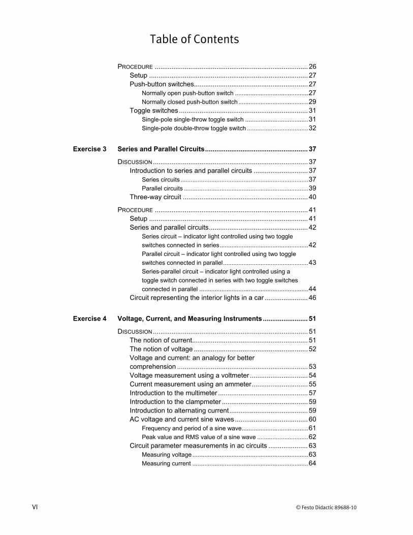
Table of Contents
VI © Festo Didactic 89688-10
PROCEDURE .................................................................................. 26 Setup ..................................................................................... 27 Push-button switches............................................................. 27
Normally open push-button switch ........................................... 27 Normally closed push-button switch ......................................... 29
Toggle switches ..................................................................... 31 Single-pole single-throw toggle switch ..................................... 31 Single-pole double-throw toggle switch .................................... 32
Exercise 3 Series and Parallel Circuits ....................................................... 37
DISCUSSION ................................................................................... 37 Introduction to series and parallel circuits ............................. 37
Series circuits ........................................................................... 37 Parallel circuits ......................................................................... 39
Three-way circuit ................................................................... 40
PROCEDURE .................................................................................. 41 Setup ..................................................................................... 41 Series and parallel circuits ..................................................... 42
Series circuit – indicator light controlled using two toggle
switches connected in series .................................................... 42 Parallel circuit – indicator light controlled using two toggle
switches connected in parallel .................................................. 43 Series-parallel circuit – indicator light controlled using a
toggle switch connected in series with two toggle switches
connected in parallel ................................................................ 44 Circuit representing the interior lights in a car ....................... 46
Exercise 4 Voltage, Current, and Measuring Instruments ........................ 51
DISCUSSION ................................................................................... 51 The notion of current.............................................................. 51 The notion of voltage ............................................................. 52 Voltage and current: an analogy for better comprehension ...................................................................... 53 Voltage measurement using a voltmeter ............................... 54 Current measurement using an ammeter .............................. 55 Introduction to the multimeter ................................................ 57 Introduction to the clampmeter .............................................. 59 Introduction to alternating current .......................................... 59 AC voltage and current sine waves ....................................... 60
Frequency and period of a sine wave ....................................... 61 Peak value and RMS value of a sine wave .............................. 62
Circuit parameter measurements in ac circuits ..................... 63 Measuring voltage .................................................................... 63 Measuring current .................................................................... 64

Table of Contents
© Festo Didactic 89688-10 VII
PROCEDURE .................................................................................. 65 Setup ..................................................................................... 65 Voltage measurements .......................................................... 66 Current measurements .......................................................... 68 Voltage and current measurements in a parallel circuit ........ 70
Exercise 5 Resistance and Ohm’s Law....................................................... 75
DISCUSSION ................................................................................... 75 The notion of resistance ........................................................ 75 Conductors and insulators ..................................................... 77 Resistance measurement using an ohmmeter ...................... 77 Ohm’s law .............................................................................. 78 Short circuits, open circuits, and continuity ........................... 79
Short circuits ............................................................................ 80 Open circuits ............................................................................ 81 Continuity ................................................................................. 81
The notion of electrical power ................................................ 82 The resistor ............................................................................ 84
Resistor color code .................................................................. 86 How to test a resistor ............................................................... 86
The variable resistor .............................................................. 87 Training system module ........................................................ 90
Resistors module ..................................................................... 90
PROCEDURE .................................................................................. 91 Setup ..................................................................................... 91 Resistance measurements using an ohmmeter .................... 91 Troubleshooting switches using an ohmmeter ...................... 94 Ohm’s law and power calculations ........................................ 96
Circuit containing a 50 Ω resistor ............................................. 96 Circuit containing a 250 Ω resistor ........................................... 99
Testing continuity of a circuit using a test light .................... 101
Exercise 6 Solving Series Circuits and Kirchhoff’s Voltage Law .......... 105
DISCUSSION ................................................................................. 105 Calculating the equivalent resistance in series circuits ....... 105 Kirchhoff’s voltage law ......................................................... 106 Voltage dividers ................................................................... 108
Voltage divider consisting of two resistors ............................. 108 Voltage divider consisting of a rheostat and a resistor ........... 109 Voltage divider consisting of a potentiometer ......................... 110

Table of Contents
VIII © Festo Didactic 89688-10
PROCEDURE ................................................................................ 111 Setup ................................................................................... 111 Equivalent resistance and Kirchhoff’s voltage law – circuit with two resistors ................................................................. 111
Solving the circuit through mathematical calculations ............ 112 Solving the circuit through circuit measurements ................... 113
Equivalent resistance and Kirchhoff’s voltage law – circuit with three resistors ............................................................... 117
Solving the circuit through mathematical calculations ............ 118 Solving the circuit through circuit measurements ................... 119
Voltage divider consisting of two resistors .......................... 122 Solving the voltage divider through mathematical
calculations............................................................................. 122 Solving the voltage divider through circuit measurements ..... 123
Light intensity control circuit implemented using a resistor and a selector switch ........................................................... 126
Exercise 7 Solving Parallel and Mixed Circuits, and Kirchhoff’s Current Law .............................................................................. 133
DISCUSSION ................................................................................. 133 Calculating the equivalent resistance in parallel circuits ..... 133 Kirchhoff’s current law ......................................................... 134 Solving mixed circuits .......................................................... 136
Example 1 .............................................................................. 136 Example 2 .............................................................................. 139
Printed circuit boards ........................................................... 142 Training system module ...................................................... 143
Printed Circuit Board module.................................................. 143
PROCEDURE ................................................................................ 144 Setup ................................................................................... 144 Calculating and measuring the voltages and currents in a parallel circuit ....................................................................... 145
Solving the circuit through mathematical calculations ............ 145 Solving the circuit through circuit measurements ................... 147
Calculating and measuring the voltages and currents in a mixed circuit ......................................................................... 150
Solving the circuit through mathematical calculations ............ 151 Solving the circuit through circuit measurements ................... 152
Light intensity control circuit connected in parallel with a resistor ................................................................................. 155
Kirchhoff’s voltage law ............................................................ 155 Kirchhoff’s current law ............................................................ 157
Resistance measurements on a printed circuit board ......... 159 Voltage measurements on a printed circuit board ............... 161
Circuit A .................................................................................. 161 Circuit B .................................................................................. 164

Table of Contents
© Festo Didactic 89688-10 IX
Exercise 8 Capacitors ................................................................................. 171
DISCUSSION ................................................................................. 171 Introduction to capacitors .................................................... 171 Operation of polarized capacitors ........................................ 172 Capacitance and voltage rating of polarized capacitors ...... 174 Capacitance measurement using a capacitance meter ...... 174 Calculating the capacitance of series and parallel capacitors ............................................................................ 176 Resistor-capacitor (RC) circuits ........................................... 178
Charging the RC circuit .......................................................... 179 Discharging the RC circuit ...................................................... 181
Applications of polarized capacitors .................................... 183 Operation of non-polarized capacitors ................................ 183 Capacitive reactance ........................................................... 187
Equivalent capacitance and capacitive reactance of series
and parallel ac capacitors ...................................................... 188 Capacitor types .................................................................... 190 How to test a capacitor ........................................................ 191 Training system module ...................................................... 191
Capacitors / Inductor module ................................................. 191
PROCEDURE ................................................................................ 193 Setup ................................................................................... 193 Safety discharge before using the capacitors ..................... 193 Measuring the capacitance of a capacitor ........................... 194 Determining the capacitance and capacitive reactance of an ac capacitor .................................................................... 195 Connecting a circuit containing a capacitor ......................... 196 Calculating the capacitance of series capacitors ................ 199 Calculating the capacitance of parallel capacitors .............. 201
Exercise 9 Electromagnetism and Inductors ........................................... 207
DISCUSSION ................................................................................. 207 Magnetism, magnets, and magnetic field ............................ 207 Electromagnetism and electromagnets ............................... 210 The solenoid ........................................................................ 211 Inductors .............................................................................. 213
Operation of inductors in dc circuits ....................................... 213 Operation of inductors in ac circuits ....................................... 215
Inductance ........................................................................... 215 Inductive reactance ............................................................. 216
Equivalent inductance and inductive reactance of series
and parallel inductors ............................................................. 217 Applications of inductors ...................................................... 218

Table of Contents
X © Festo Didactic 89688-10
PROCEDURE ................................................................................ 219 Setup ................................................................................... 219 Troubleshooting an inductor using an ohmmeter ................ 219 Calculating the inductive reactance of an inductor .............. 220 Connecting a circuit containing an inductor ......................... 221 Calculating the reactance of inductors connected in series ................................................................................... 222 Calculating the reactance of inductors connected in parallel ................................................................................. 224
Exercise 10 Transformers ............................................................................ 229
DISCUSSION ................................................................................. 229 Introduction to transformers ................................................. 229 Transformer operation ......................................................... 230 Transformer turns, voltage, and current ratios .................... 231 Step-up and step-down transformers .................................. 233
Step-up transformers .............................................................. 233 Step-down transformers ......................................................... 234
Transformer voltage regulation ............................................ 235 Magnetizing current ............................................................. 236 Types of transformers .......................................................... 237
Control transformers ............................................................... 237 Power transformers ................................................................ 237 Isolation transformers ............................................................. 238
Training system module ...................................................... 238 Control Transformer module ................................................... 238
PROCEDURE ................................................................................ 240 Setup ................................................................................... 240 Calculating the ratios and ratings of a transformer .............. 240 Troubleshooting a transformer ............................................ 243 Measuring the ratios and ratings of a transformer ............... 246 Transformer voltage regulation ............................................ 250
Exercise 11 Relays and Contactors ............................................................ 255
DISCUSSION ................................................................................. 255 Introduction to relays ........................................................... 255 Operation of dc relays ......................................................... 256 Operation of ac relays ......................................................... 258 Relay applications ................................................................ 259 Contactors ........................................................................... 259 Two-wire and three-wire control circuits .............................. 260
Two-wire control circuit ........................................................... 260 Three-wire control circuit ........................................................ 261

Table of Contents
© Festo Didactic 89688-10 XI
Training system modules ..................................................... 262 Relays module ....................................................................... 262 Contactors module ................................................................. 263 Residential Bimetallic Thermostat module ............................. 264
PROCEDURE ................................................................................ 265 Setup ................................................................................... 265 Troubleshooting a relay ....................................................... 266 Controlling two indicator lights using a relay ....................... 268 Two-wire control circuit ........................................................ 269
Thermostat operation ............................................................. 269 Heating element controlled using a thermostat and a
contactor ................................................................................ 270 Thermostat heat anticipator setting ........................................ 271 Contactor push-to-test button ................................................. 272
Three-wire control circuit ..................................................... 272 Circuit representing a blower motor controlled using
start/stop push buttons and a contactor ................................. 272
Exercise 12 Semiconductors ....................................................................... 277
DISCUSSION ................................................................................. 277 Introduction to semiconductors ............................................ 277 The diode ............................................................................. 277
Operating principles of a diode .............................................. 278 Characteristic voltage-current curve of a diode ...................... 280 Diode types ............................................................................ 281 Procedure to test a diode using a multimeter ......................... 281
Single-phase half-wave rectifier .......................................... 282 The light-emitting diode (LED) ............................................. 284
PROCEDURE ................................................................................ 286 Setup ................................................................................... 286 Testing a diode using a multimeter ...................................... 286 Single-phase half-wave rectifier .......................................... 288
Operation without rectification ................................................ 288 Operation with rectification ..................................................... 289 Operation with rectification and filtering ................................. 291
Light-emitting diode ............................................................. 293

Table of Contents
XII © Festo Didactic 89688-10
Exercise 13 Electrical Distribution .............................................................. 297
DISCUSSION ................................................................................. 297 Introduction to the power network and distribution network ................................................................................ 297 Three-phase circuits ............................................................ 299
Phase sequence ..................................................................... 299 Wye and delta configurations ................................................. 301 Distinction between line and phase voltages, and line and
phase currents ........................................................................ 301 Circuit protection .................................................................. 303
Fuses ..................................................................................... 303 Circuit breakers ...................................................................... 304 Magnetic circuit breakers ....................................................... 305 Thermal circuit breakers ......................................................... 306 Ground fault circuit interrupter GFCI breaker ......................... 307 Circuit breaker symbols .......................................................... 307
Electrical panels ................................................................... 307 Disconnect switch ................................................................ 308 Power circuit versus control circuit ...................................... 309
Power circuit ........................................................................... 310 Control circuit ......................................................................... 310
Training system modules ..................................................... 310 Circuit Breaker module ........................................................... 310 Disconnect Switch module ..................................................... 311
PROCEDURE ................................................................................ 312 Setup ................................................................................... 312 Operation of a fuse .............................................................. 312 Operation of a circuit breaker .............................................. 314
Circuit with an excessive load ................................................ 314 Short-circuited circuit breaker ................................................. 316
Resistance, current, and voltage measurements in a disconnect switch ................................................................. 317
Current measurement ............................................................ 321 Voltage measurement ............................................................ 322
Exercise 14 Troubleshooting Methods ....................................................... 325
DISCUSSION ................................................................................. 325 Introduction to troubleshooting ............................................ 325 The voltmeter method .......................................................... 326 The ohmmeter method ........................................................ 327
PROCEDURE ................................................................................ 328 Setup ................................................................................... 329 Guided troubleshooting of a heating circuit ......................... 329
Voltmeter method ................................................................... 331 Ohmmeter method ................................................................. 332
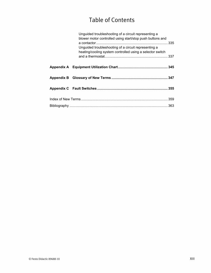
Table of Contents
© Festo Didactic 89688-10 XIII
Unguided troubleshooting of a circuit representing a blower motor controlled using start/stop push buttons and a contactor ........................................................................... 335 Unguided troubleshooting of a circuit representing a heating/cooling system controlled using a selector switch and a thermostat .................................................................. 337
Appendix A Equipment Utilization Chart .................................................... 345
Appendix B Glossary of New Terms ........................................................... 347
Appendix C Fault Switches .......................................................................... 355
Index of New Terms ........................................................................................... 359
Bibliography ....................................................................................................... 363


© Festo Didactic 89688-10 XV
Preface
Electricity is used in all aspects of modern society, be it in residential, commercial, or industrial applications. It is used for lighting, heating, refrigerating, ventilating, transport, communications, computations, and a host of other functions. While most power networks in the world operate in alternating current, direct current is also commonly used in applications that require low voltage or that use batteries as a power source.
The Electricity Fundamentals Training System, Model 3460, is a complete introduction to electricity and to the electrical components used in HVAC systems. Through this program, you will learn how to connect, perform measurements, calculate, and troubleshoot circuits.
Although electricity has been known to Man since ancient times, it is only in modern times that it began to be commonly used as a power source (photo courtesy of Postdlf).
We invite readers of this manual to send us their tips, feedback, and suggestions for improving the book.
Please send these to [email protected].
The authors and Festo Didactic look forward to your comments.


© Festo Didactic 89688-10 XVII
About This Manual
Manual objectives
When you have completed this manual, you will be familiar with the basic concepts of electricity. You will be able to define voltage, current, resistance, power, and capacitance, and know how to measure these parameters using their respective measuring instruments. You will know the difference between dc and ac circuits. You will be introduced to the most common components used: power sources, switches, resistors, capacitors, inductors, solenoids, and relays. You will know what series and parallel circuits are, and be able to calculate the equivalent resistance and capacitance of series and parallel components. You will be familiar with Ohm’s law, as well as Kirchhoff’s voltage and current laws, and be able to apply these laws to electrical circuits. You will be introduced to the notions of magnetism and electromagnetism.
Safety considerations
Safety symbols that may be used in this manual and on the equipment are listed in the Safety Symbols table at the beginning of the manual.
Safety procedures related to the tasks that you will be asked to perform are indicated in each exercise.
Make sure that you are wearing appropriate protective equipment when performing the tasks. You should never perform a task if you have any reason to think that a manipulation could be dangerous for you or your teammates.
Systems of units
Units are expressed using the International System of Units (SI) followed by the units expressed in the U.S. customary system of units (between parentheses).


© Festo Didactic 89688-10 XIX
To the Instructor
You will find in this Instructor Guide all the elements included in the Student Manual together with the answers to all questions, results of measurements, graphs, explanations, suggestions, and, in some cases, instructions to help you guide the students through their learning process. All the information that applies to you is placed between markers and appears in red.
Accuracy of measurements
The numerical results of the hands-on exercises may differ from one student to another. For this reason, the results and answers given in this manual should be considered as a guide. Students who correctly performed the exercises should expect to demonstrate the principles involved and make observations and measurements similar to those given as answers.

Sample Exercise
Extracted from
the Student Manual
and the Instructor Guide


© Festo Didactic 89688-10 75
When you have completed this exercise, you will be familiar with the notion of resistance, and know how to measure this parameter using an ohmmeter. You will be introduced to Ohm’s law, and be able to calculate voltage, current, and resistance in electrical circuits. You will also know the concepts of conductors, insulators, short circuits, open circuits, and continuity in electrical circuits. You will also be familiar with the concept of power. Finally, you will be introduced to the Resistors module.
The Discussion of this exercise covers the following points:
The notion of resistance Conductors and insulators Resistance measurement using an ohmmeter Ohm’s law Short circuits, open circuits, and continuity
Short circuits. Open circuits. Continuity. The notion of electrical power The resistor
Resistor color code. How to test a resistor. The variable resistor Training system module
Resistors module.
The notion of resistance
Together with voltage and current, another notion is necessary to understand electricity: resistance. The resistance of a material represents the opposition of the material to current flow. The higher the resistance of the material, the more it prevents the flow of charge carriers. Resistance is measured in ohms (Ω) after German physicist and mathematician Georg Ohm who discovered the relationship between voltage, current, and resistance. In this manual, resistance is denoted using the letter .
It is also possible to use the analogy of the water circuit to better understand the notion of resistance. In this analogy, resistance represents the size of the water pipe, as shown in Figure 62.
Resistance and Ohm’s Law
Exercise 5
EXERCISE OBJECTIVE
DISCUSSION OUTLINE
DISCUSSION
Exercise 5 – Resistance and Ohm’s Law Discussion
76 © Festo Didactic 89688-10
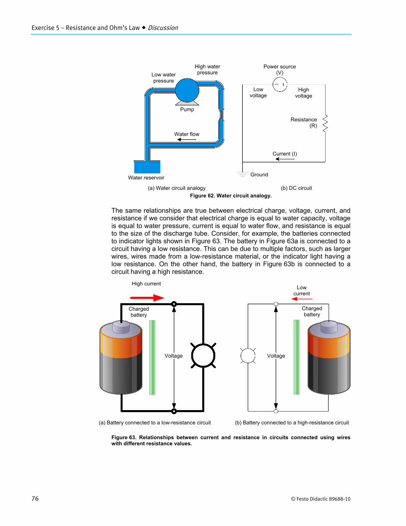
Figure 62. Water circuit analogy.
The same relationships are true between electrical charge, voltage, current, and resistance if we consider that electrical charge is equal to water capacity, voltage is equal to water pressure, current is equal to water flow, and resistance is equal to the size of the discharge tube. Consider, for example, the batteries connected to indicator lights shown in Figure 63. The battery in Figure 63a is connected to a circuit having a low resistance. This can be due to multiple factors, such as larger wires, wires made from a low-resistance material, or the indicator light having a low resistance. On the other hand, the battery in Figure 63b is connected to a circuit having a high resistance.
Figure 63. Relationships between current and resistance in circuits connected using wires with different resistance values.
Voltage Voltage
Charged battery
Charged battery
High current Low
current
(a) Battery connected to a low-resistance circuit (b) Battery connected to a high-resistance circuit
Pump
Low water pressure
Water flow
(a) Water circuit analogy (b) DC circuit
High waterpressure
Water reservoir
Power source (V)
Resistance(R)
Ground
Current (I)
Low voltage
High voltage

Exercise 5 – Resistance and Ohm’s Law Discussion
© Festo Didactic 89688-10 77
Conductors and insulators
Depending on their resistance, materials can be classified in two categories: conductors and insulators.
Conductors have a low resistance value, which means that they easily allow the flow of current. Examples of good conductors include most metals, with copper being by far the most commonly used. Atoms in a conductive material have their outer electron(s) loosely bonded. Some of those electrons would gladly propagate through the conductor lattice in the presence of an external force such as the one created by a electric field.
Insulators, on the other hand, have a high resistance value, which means that they impede or prevent the flow of charge carriers. The outer electrons of the atoms in an insulator are tightly bound, which prevents them to move freely and thus prevents current flow. Examples of good insulators include glass, paper, Teflon, most plastics, and ceramic. Insulators are used in applications where preventing the flow of electrical current is required, such as in circuit boards, in electrical wire sleeves and coating, and to insulate transmission lines.
Resistance measurement using an ohmmeter
Resistance is measured using an ohmmeter. Just like a voltmeter, an ohmmeter measures the resistance between two points in a circuit. Because of this, it is necessary to connect the ohmmeter across (i.e., in parallel with) the two points where resistance is to be measured, such as across the terminals of a load. This is shown in Figure 64. In the figure, the indicator light has a resistance of 25 Ω. Therefore, when an ohmmeter is connected in parallel with the indicator light, it indicates a resistance of 25 Ω.
Figure 64. Using an ohmmeter to measure the resistance of an indicator light.
An ohmmeter operates by applying a small voltage across the terminals to which it is connected, then measuring the current flowing through it. Using Ohm’s law (covered in the next section of this exercise), the ohmmeter then calculates the resistance across its terminals. Due to its mode of operation, it is very important to use an ohmmeter only in circuits whose power source is removed. Doing otherwise could seriously damage the ohmmeter, as well as providing inaccurate measurements.
Ohmmeter
Indicator light25 Ω
+ COM
25 Ω

Exercise 5 – Resistance and Ohm’s Law Discussion
78 © Festo Didactic 89688-10
Just like all other components in an electrical circuit, ohmmeters have a circuit diagram symbol. The symbol shown in Table 11 is used in this manual to represent an ohmmeter.
Table 11. Ohmmeter symbol.
Component Symbol
Ohmmeter
Representing the ohmmeter in Figure 64 using its circuit diagram symbol results in the following circuit.
Figure 65. Using an ohmmeter to measure the resistance of an indicator light.
Ohm’s law
The mathematical relationship between voltage, current, and resistance is credited to Georg Ohm and therefore is called Ohm’s law. This law is expressed below:
(5)
where is the current flowing in a conductor, expressed in amperes (A) is the voltage applied across the conductor, expressed in volts (V) is the resistance of the conductor, expressed in ohms (Ω)
Ohm’s law can be reformulated in the following two equations:
(6)
(7)
As these equations show, whenever two of the three parameters (voltage, current, and resistance) of a conductor or circuit are known, the other parameter
Indicator light

Exercise 5 – Resistance and Ohm’s Law Discussion
© Festo Didactic 89688-10 79
can be calculated. These equations also show that, for a given resistance, the current flowing in a conductor or circuit is directly proportional to the voltage applied to it. For example, if the voltage doubles, the current also doubles.
Consider, for example, the circuit shown in Figure 66 of a power source connected to an indicator light. Suppose that we know two of the three parameters of the circuit and that we want to calculate the third using Ohm’s law. The following three cases show an example for each possible missing parameter (current, voltage, and resistance, respectively).
If the power source voltage is equal to 24 V and the resistance of the indicator light is equal to 50 Ω, it is possible to calculate the source current flowing in the circuit using the following equation:
24
50Ω0.48
Alternatively, if the source current flowing in the circuit is equal to 0.8 A and the resistance of the indicator light is equal to 62.5 Ω, it is possible to calculate the power source voltage using the following equation:
0.8 62.5Ω 50
Finally, if the power source voltage is equal to 100 V and the source current flowing in the circuit is equal to 0.25 A, it is possible to calculate the indicator light resistance using the following equation:
100
0.25400Ω
Figure 66. Power source connected to an indicator light.
Short circuits, open circuits, and continuity
Now that we are able to calculate the current using Ohm’s law, we can look at three important notions related to the resistance of a circuit: short circuits, open circuits, and continuity.
Power source
Indicator light

Exercise 5 – Resistance and Ohm’s Law Discussion
80 © Festo Didactic 89688-10
Short circuits
A short circuit occurs when electrical current is allowed to flow in a circuit along a path that was not at first intended, most often along a path whose resistance is much lower than that of the normal path. A typical short circuit involves bypassing the load altogether, thus making the circuit resistance tend toward 0 Ω. Using Ohm’s law for calculating current ( / ), it is easy to calculate that, for a given voltage, a resistance that tends toward 0 Ω causes the current to increase to a very high value. Consider, for example, the circuit in Figure 67 showing a power network (represented by the transmission lines and power equipment) supplying electrical current to a domestic house.
Figure 67. Circuits illustrating the effects of a short circuit.
In Figure 67a, current passes through the house and is therefore limited by the house resistance (i.e., by the combined resistance of all electrical equipment in the house). In Figure 67b, however, a short circuit is added that enables current to flow without passing through the house. This could represent, for example, a tree that fell on the transmission lines, causing the two lines to connect. When following the short circuit, current is limited only by the wire resistance, which is very low (wires are designed to prevent the flow of current as little as possible). Because of this, while current will continue to flow normally in the house, an extremely high current will flow in the short circuit. Such a current causes the wires to overheat and could potentially damage the power equipment. Short circuits are thus highly undesirable.
It is possible to identify a short circuit between two points in a circuit by measuring the resistance across these two points using an ohmmeter. If the ohmmeter indicates that the resistance across the two points is equal to 0 Ω, or very close to it, a short circuit is present between the points. In that case, verify the circuit connections to locate and remove the short circuit.
(a) Circuit without short circuit (a) Circuit with short circuit
House rated current
Very high current
Short circuit
Power equipment
Power equipment House rated
current
To power source
To power source
To power source
To power source

Exercise 5 – Resistance and Ohm’s Law Discussion
© Festo Didactic 89688-10 81
Open circuits
An open circuit occurs when there is no longer any path for current to flow in a circuit. In other words, the circuit resistance is infinite. Using Ohm’s law for calculating current ( / ) confiRMS that, when the circuit resistance is infinite, no current flows through it.
Open circuits can happen voluntarily, such as when a switch is set to its open state. Open circuits can also happen by accident, either due to faulty connections or to malfunctioning equipment. A common example of malfunctioning equipment causing an open circuit is a burned out light bulb. This happens because the tungsten wire breaks, thereby removing any contact between the conducting wires and causing the light bulb to be in open circuit condition.
It is possible to identify an open circuit between two points in a circuit by measuring the resistance across those two points using an ohmmeter. If the ohmmeter indicates that the resistance across the two points is infinite (or overload), an open circuit is present between the points.
Continuity
Continuity between two points in a circuit simply indicates that electrical current can flow between the two points and therefore that the circuit is not open.
It is possible to determine whether there is continuity between two points in a circuit by measuring the resistance across these two points using an ohmmeter. If the ohmmeter indicates that the resistance across the two points is anything but infinite, there is continuity between the points. Testing for continuity is an important tool when troubleshooting (i.e., when searching for faults in) faulty circuits. It enables the location of wrongly connected wires and malfunctioning equipment.
When no ohmmeter is available for continuity testing, it is also possible to setup a small continuity testing circuit such as the one in Figure 68. Terminals A and B of this test light circuit are connected to each of the two points between which continuity is to be measured. When the power source is turned on, the indicator light turns on if there is continuity between the two points and remains turned off if not. The measuring instrument called a continuity tester basically consists of standard batteries, and a buzzer or a small light.
Figure 68. Indicator light circuit used for testing continuity.
Indicator light
Powersource
A
B

Exercise 5 – Resistance and Ohm’s Law Discussion
82 © Festo Didactic 89688-10
Figure 69 shows a circuit where continuity can be measured at different points in the circuit using an ohmmeter. Note that the switches are considered to be in the state in which they are shown in the circuit and the power source is turned off.
Figure 69. Circuit for measuring continuity between different points.
Continuity is examined in the following points:
B-C: There is no continuity between these points because the toggle switch is in its open state, thereby preventing current flow.
D-E: There is no continuity between these points because the NO push-button switch is in its open state, thereby preventing current flow.
F-G: There is continuity between these points because the NO push-button switch is in its closed state, thereby allowing current flow.
A-H: There is continuity between these points because, even though two of the three switches are in their open state, one is in its closed state, thereby allowing current flow.
H-I: Normally, there is continuity between the terminals of the indicator light because this device allows current flow (it has a definite current value). However, the device can possibly malfunction (such as if it is burned out) and prevent current flow. In this case, there would be no continuity.
The notion of electrical power
Power is defined as the rate at which work is produced. Power thus depends on time. Electrical power is measured in watts (W) after Scottish inventor and mechanical engineer James Watt, who developed the concept of horsepower. Power is usually denoted using the letter , and can be measured using a wattmeter. Wattmeters, however, are less common than voltmeters, ammeters, and ohmmeters and are not covered in this manual. You will see later that power can be calculated using the other circuit parameters.
A B C
D E
F G
H
I
Powersource
Indicator light

Exercise 5 – Resistance and Ohm’s Law Discussion
© Festo Didactic 89688-10 83
The electrical power supplied by a power source depends on the power source voltage and current. Similarly, the electrical power dissipated by a load depends on the voltage that is applied to it and on the current that flows through it. Both can be calculated using the following equation.
(8)
where is the electrical power, expressed in watts (W) is the voltage of the power source or applied to the load, expressed
in volts (V) is the current of the power source or flowing through the load,
expressed in amperes (A)
When used in conjunction with Ohm’s law, it is possible to calculate any parameter between voltage, current, resistance, and power, as long as at least two of these parameters are known. All possible variants of the equation are summarized in the following chart. Each parameter in the center is equal to each expression located in its quarter of the circle.
Figure 70. Chart for calculating voltage, current, resistance, and power from any two other parameters.
√

Exercise 5 – Resistance and Ohm’s Law Discussion
84 © Festo Didactic 89688-10
Consider, for example, the circuit shown in Figure 71 of a power source connected to an indicator light.
Figure 71. Circuit for power calculations.
If the voltage applied to the indicator light is equal to 40 V and the resistance of the indicator light is equal to 50 Ω, it is possible to calculate the power supplied to the indicator light using the following equation:
40
50Ω32W
Alternatively, if the indicator light has a resistance of 25 Ω and it consumes a power of 40 W, it is possible to calculate the current flowing in the circuit using the following equation:
40W
25Ω1.265
It is also possible to calculate the power rating of the power source from its voltage and current ratings. For example, if its voltage rating . is equal to 24 V and its current rating . is equal to 4 A, the power source rating . can be calculated using the following equation:
. . . 24 4A 96W
This value indicates the maximal power that the power source can supply to a load. Using a power source to supply more power than its ratings can cause overheating and seriously damage the power source.
The resistor
Resistors are common electrical components that are designed to have a specific resistance value. Resistors are very common elements of electronic circuits, being found in almost all electronic devices. Figure 72 shows a selection of resistors of various sizes and resistance values.
Power source
Indicator light

Exercise 5 – Resistance and Ohm’s Law Discussion
© Festo Didactic 89688-10 85
Figure 72. Selection of resistors of various sizes and resistance values (photo courtesy of Riedon, all rights reserved).
An important property of resistors is that they limit the flow of current in a circuit. By connecting a resistor in series in a circuit, it is thus possible to decrease and control the amount of current in the circuit.
Another important property of resistors is that they convert electrical energy into heat. The higher the current flowing in the resistor, the more heat it produces. This property can be detrimental in certain circuits, as the heat generated may be undesirable and thus requires to be evacuated from the device using a fan, such as in a computer. However, the heat generated by a resistor can also be the purpose of its use. For example, most of the heating elements used for cooking are resistors. Other examples include electric baseboards, water heaters, and fan heaters. The filament in an incandescent light bulb is also essentially a resistor. Usually the size of a resistor is an indication of its ability to dissipate heat. The bigger the resistor is, the more heat it can dissipate.
Like most electrical components, resistors have a certain tolerance, which indicates by how much their resistance can vary from the nominal rating. The tolerance of a resistor is generally expressed as a percentage of its nominal resistance, and can be as low as 1% for high-precision resistors to about 20%.
The circuit diagram symbol for a resistor is shown in Table 12.
Table 12. Resistor symbol.
Component Symbol
Resistor or

Exercise 5 – Resistance and Ohm’s Law Discussion
86 © Festo Didactic 89688-10
Resistor color code
The resistance value of axial resistors, such as the one shown below, is often marked on the resistor body using a color code. Most resistors have four bands (sometimes five bands when more precision is desired). The color of the first and second bands indicates the first and second digits of the resistance value. The third band indicates the multiplier value, and the fourth band indicates the tolerance value.
Table 13. Resistor color code.
Color FirstBand
SecondBand
Multiplier Tolerance
Black 0 0 1
Brown 1 1 10 ±1%
Red 2 2 100 ±2%
Orange 3 3 1000
Yellow 4 4 10 000
Green 5 5 100 000
Blue 6 6 1 000 000
Violet 7 7 10 000 000
Gray 8 8 100 000 000
White 9 9 1 000 000 000
Gold ±5%
Silver ±10%
For instance, the resistance of the resistor shown in Table 13 is 100 Ω ±5%. The first band is brown (this corresponds to digit 1), the second band is black (this corresponds to digit 0), the third band is brown (this corresponds to a multiplier of 10), and the fourth band is gold (this corresponds to a tolerance of ±5%).
The resistance value of high-power resistors is usually printed on the resistor body. When the resistance of a resistor equals or exceeds 1000 Ω it is usually expressed in kilohms (kΩ). For instance, a 4700 Ω resistor is expressed as a 4.7 kΩ resistor.
The characteristics to consider when selecting or replacing a resistor are the size, nominal resistance, operating temperature range, rated power, tolerance, resistance range, rated voltage, and maximum operating voltage.
How to test a resistor
A resistor is tested by measuring its resistance using an ohmmeter. The measured resistance should be within the range of the nominal value indicated on the resistor. If the measured resistance is null or infinite, the resistance needs to be replaced. Make sure that the resistor is isolated from the circuit during the measurement.
Exercise 5 – Resistance and Ohm’s Law Discussion
© Festo Didactic 89688-10 87
The resistance can also be determined by applying a voltage across the resistor, and measuring the voltage and the current flowing through it. The measured voltage and current are then used to calculate the resistance.
The variable resistor
A variable resistor is a resistor whose resistance can be adjusted in a predetermined range. This enables the resistor to be used for accurate current control, as the resistance of the variable resistor can be adjusted between different values as required to control the amount of current flowing in the circuit. Variable resistors also allow connection of a voltage divider, a device that allows the output voltage of the resistor to be adjusted to a variable fraction of the input voltage. Voltage dividers are covered in the next exercise.
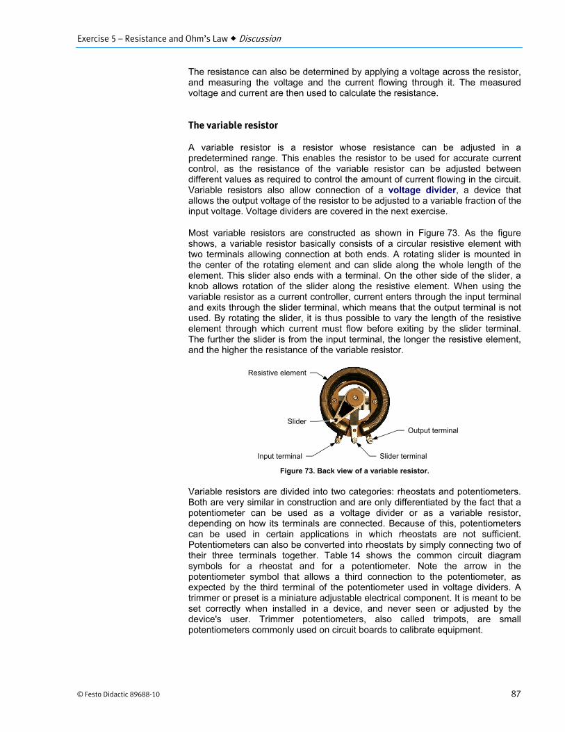
Most variable resistors are constructed as shown in Figure 73. As the figure shows, a variable resistor basically consists of a circular resistive element with two terminals allowing connection at both ends. A rotating slider is mounted in the center of the rotating element and can slide along the whole length of the element. This slider also ends with a terminal. On the other side of the slider, a knob allows rotation of the slider along the resistive element. When using the variable resistor as a current controller, current enters through the input terminal and exits through the slider terminal, which means that the output terminal is not used. By rotating the slider, it is thus possible to vary the length of the resistive element through which current must flow before exiting by the slider terminal. The further the slider is from the input terminal, the longer the resistive element, and the higher the resistance of the variable resistor.
Figure 73. Back view of a variable resistor.
Variable resistors are divided into two categories: rheostats and potentiometers. Both are very similar in construction and are only differentiated by the fact that a potentiometer can be used as a voltage divider or as a variable resistor, depending on how its terminals are connected. Because of this, potentiometers can be used in certain applications in which rheostats are not sufficient. Potentiometers can also be converted into rheostats by simply connecting two of their three terminals together. Table 14 shows the common circuit diagram symbols for a rheostat and for a potentiometer. Note the arrow in the potentiometer symbol that allows a third connection to the potentiometer, as expected by the third terminal of the potentiometer used in voltage dividers. A trimmer or preset is a miniature adjustable electrical component. It is meant to be set correctly when installed in a device, and never seen or adjusted by the device's user. Trimmer potentiometers, also called trimpots, are small potentiometers commonly used on circuit boards to calibrate equipment.
Input terminal
Output terminal
Slider terminal
Slider
Resistive element

Exercise 5 – Resistance and Ohm’s Law Discussion
88 © Festo Didactic 89688-10
Table 14. Rheostat and potentiometer symbols.
Component Symbol
Rheostat
or
Potentiometer
or
Figure 74 shows an example of a circuit containing a rheostat. In this circuit, the rheostat is used to make a dimmer, which is a light switch allowing the intensity of the light to be varied. This is achieved by increasing or decreasing the resistance of the rheostat. The higher its resistance, the lower the current flowing in the light and the less intensity it produces.
Figure 74. Circuit of a power source supplying power to a dimmer.
Suppose the light bulb has a resistance of 144 Ω and the rotating knob of the dimmer is set so that the dimmer resistance . is maximal (1000 Ω). Since the power source voltage is equal to 120 V (RMS)3, the current flowing in the circuit is equal to:
.
120
1144Ω0.10
The power . dissipated in the dimmer is thus equal to:
. . 1000Ω 0.10 10W
The power dissipated in the light is:
144Ω 0.10 1.4W
3 Unless specified, line current and voltage are always RMS values.
120 V
Dimmer .
0 Ω to 1000 Ω
Light
144 Ω

Exercise 5 – Resistance and Ohm’s Law Discussion
© Festo Didactic 89688-10 89
Since the power dissipated in the light is very low, the resultant lighting is weak. On the other hand, if the rotating knob of the dimmer is set so that the dimmer resistance . is small (100 Ω), the current flowing in the circuit is equal to:
.
120
244Ω≅ 0.49
The power . dissipated in the dimmer is thus equal to:
. . 100Ω 0.49 24W
The power dissipated in the light is:
144Ω 0.49 35W
Finally, if the dimmer is set to 0 Ω, we have:
120
144Ω≅ 0.833
The power dissipated in the light is:
144Ω 0.833 100W

Exercise 5 – Resistance and Ohm’s Law Discussion
90 © Festo Didactic 89688-10
Training system module
Resistors module
Figure 75. Resistors module.
The Resistors module consists of resistors having various ratings. All resistors have a tolerance of 5%. The module is provided with some openings to dissipate heat. The Resistors module is also equipped with four fault switches and two ground terminals.
Resistor
Ground terminal Fault switches
IEC symbol for a resistor

Exercise 5 – Resistance and Ohm’s Law Procedure Outline
© Festo Didactic 89688-10 91
The Procedure is divided into the following sections:
Setup Resistance measurements using an ohmmeter Troubleshooting switches using an ohmmeter Ohm’s law and power calculations
Circuit containing a 50 Ω resistor. Circuit containing a 250 Ω resistor. Testing continuity of a circuit using a test light
High voltages are present in this laboratory exercise. Do not make or modify anybanana jack connections with the power on unless otherwise specified.
Setup
In this section, you will install the training system modules in the workstation.
1. Refer to the Equipment Utilization Chart in Appendix A to obtain the list of equipment required to perform this exercise.
Install the equipment required in the workstation.
Make sure that all fault switches are set to the O (off) position.
Resistance measurements using an ohmmeter
In this section, you will use an ohmmeter to measure the resistance across the resistors of the Resistors module, and verify if the measured values are within the tolerance indicated on the front panel of the module. You will also measure the resistance of an indicator light. Then, you will determine whether these components allow continuity or not.
2. Select the ohmmeter (Ω) function of the multimeter.
Touch the probe tips together and read the resistance on the display.
Resistance on the display when the probe tips are touching Ω
Resistance on the display when the probe tips are touching = 0 Ω
3. Isolate the probe tips and read the resistance on the display.
Resistance on the display when the probe tips are isolated Ω
Resistance on the display when the probe tips are isolated = infinite resistance value. Depending on the ohmmeter used, an infinite resistance value may be indicated by a 1, OL, or Overflow on the display.
PROCEDURE OUTLINE
PROCEDURE
Exercise 5 – Resistance and Ohm’s Law Procedure
92 © Festo Didactic 89688-10
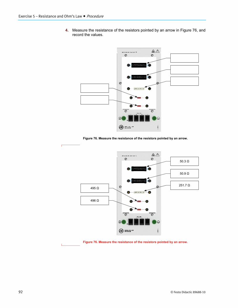
4. Measure the resistance of the resistors pointed by an arrow in Figure 76, and record the values.
Figure 76. Measure the resistance of the resistors pointed by an arrow.
Figure 76. Measure the resistance of the resistors pointed by an arrow.
50.3 Ω
50.9 Ω
251.7 Ω 495 Ω
496 Ω

Exercise 5 – Resistance and Ohm’s Law Procedure
© Festo Didactic 89688-10 93
5. Are the measured resistances within the tolerance of the resistors indicated on the front panel of the Resistors module?
Yes No
Yes
6. Compare the size of the resistors (50 Ω, 250 Ω, and 500 Ω) of the Resistors module. What can you conclude about the size of these resistors versus the power they can dissipate?
The resistors having a higher power rating are bigger.
7. On the Printed Circuit Board module, locate and observe the size of resistors , , . What can you deduce about the power these resistors can
dissipate?
a Resistors , , are specially designed to be mounted on printed circuit boards. This type of resistor is called surface-mount resistor.
The Printed Circuit Board module will be explained in Exercise 7.
The power that these resistors can dissipate is very low.
8. On the Indicator Lights module, measure the resistance across a 24 V indicator light. Record the value below.
Indicator light resistance Ω
Indicator light resistance 33 Ω (approximately)
9. Do your measurements in this section confirm that the indicator light operates properly?
Yes No
Yes
Exercise 5 – Resistance and Ohm’s Law Procedure
94 © Festo Didactic 89688-10
10. What can you conclude from the resistance values you measured in steps 4 and 6 about the continuity between the terminals of the different components? Briefly explain.
The resistance values measured in steps 4 and 6 are different from infinity, which means that current can flow reasonably freely in the components. This confirms that there is continuity between the terminals of the different components.
Troubleshooting switches using an ohmmeter
In this section, you will use an ohmmeter to measure the resistance across the switches of the Switches module and of the Push Buttons module in different states. Then, you will use the measured resistance values to determine whether the switches operate properly or not.
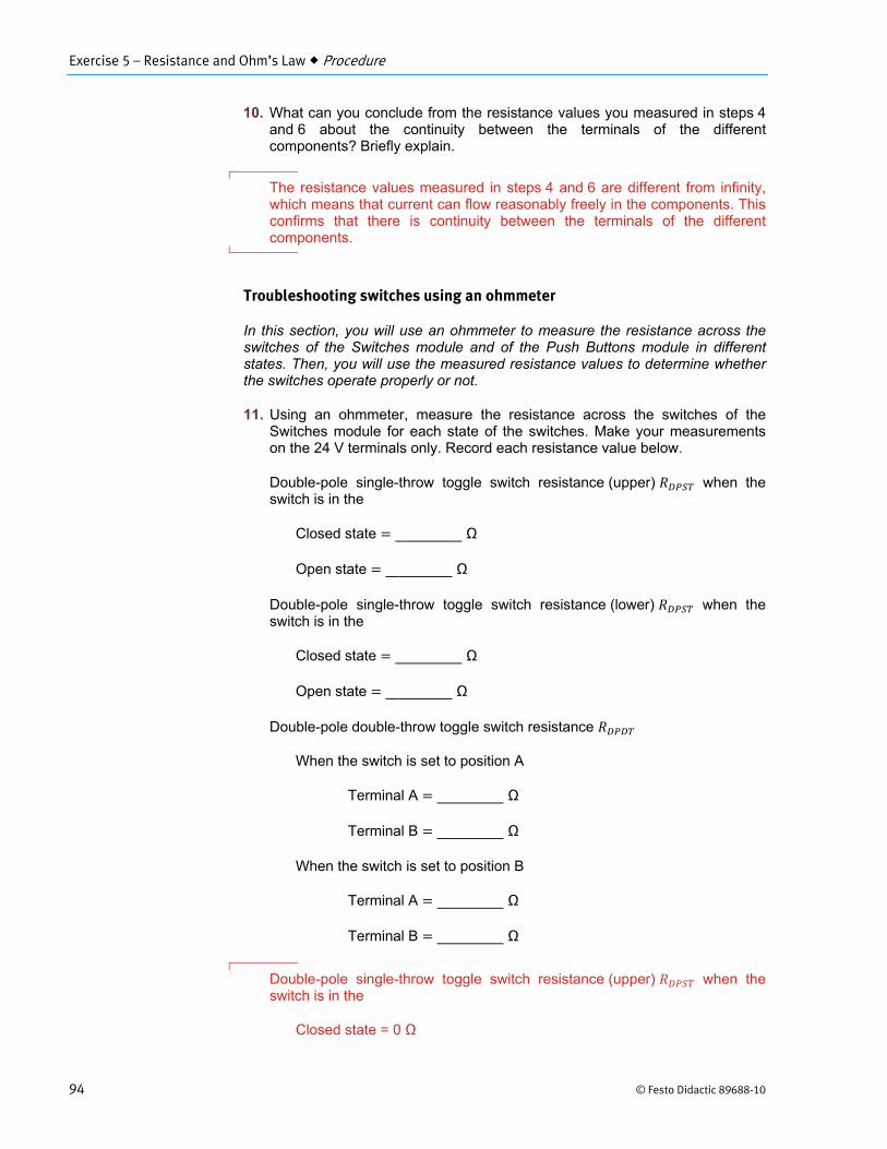
11. Using an ohmmeter, measure the resistance across the switches of the Switches module for each state of the switches. Make your measurements on the 24 V terminals only. Record each resistance value below.
Double-pole single-throw toggle switch resistance (upper) when the switch is in the
Closed state Ω
Open state Ω
Double-pole single-throw toggle switch resistance (lower) when the switch is in the
Closed state Ω
Open state Ω
Double-pole double-throw toggle switch resistance
When the switch is set to position A
Terminal A Ω
Terminal B Ω
When the switch is set to position B
Terminal A Ω
Terminal B Ω
Double-pole single-throw toggle switch resistance (upper) when the switch is in the
Closed state = 0 Ω

Exercise 5 – Resistance and Ohm’s Law Procedure
© Festo Didactic 89688-10 95
Open state = infinite resistance value
Double-pole single-throw toggle switch resistance (lower) when the switch is in the
Closed state = 0 Ω
Open state = infinite resistance value
Double-pole double-throw toggle switch resistance
When the switch is set to position A
Terminal A = 0 Ω
Terminal B = infinite resistance value
When the switch is set to position B
Terminal A = infinite resistance value
Terminal B = 0 Ω
12. Measure the resistance across the push buttons of the Push Buttons module for each state of the push buttons. Make your measurements on the 24 V terminals only. Record each resistance value below.
NO push button resistance when the push button is in the
Pressed state Ω
Released state Ω
NC push button resistance when the push button is in the
Pressed state Ω
Released state Ω
NO push button resistance when the push button is in the
Pressed state 0Ω
Released state = infinite resistance value
NC push button resistance when the push button is in the
Pressed state = infinite resistance value
Released state 0Ω
Exercise 5 – Resistance and Ohm’s Law Procedure
96 © Festo Didactic 89688-10
13. Do the measurements you made in steps 11 and 12 confirm that all switches operate properly? Briefly explain.
Yes. The ohmmeter indicated almost no resistance whenever measuring the resistance across a closed switch, or across closed terminals of the DPDT switch. Conversely, the ohmmeter indicated an infinite resistance whenever measuring the resistance across an open switch, or across open terminals of the DPDT switch. Therefore, all switches allow current to flow when closed and prevent current to flow when open, as expected in theory.
Ohm’s law and power calculations
In this section, you will connect two circuits: one containing a 50 Ω resistor, and the other containing a 250 Ω resistor. For each circuit, you will calculate different parameters of the circuit using Ohm’s law. You will then validate the calculated values by making voltage and current measurements in the circuit. You will also calculate the amount of power consumed by the resistor in each circuit.
Circuit containing a 50 Ω resistor
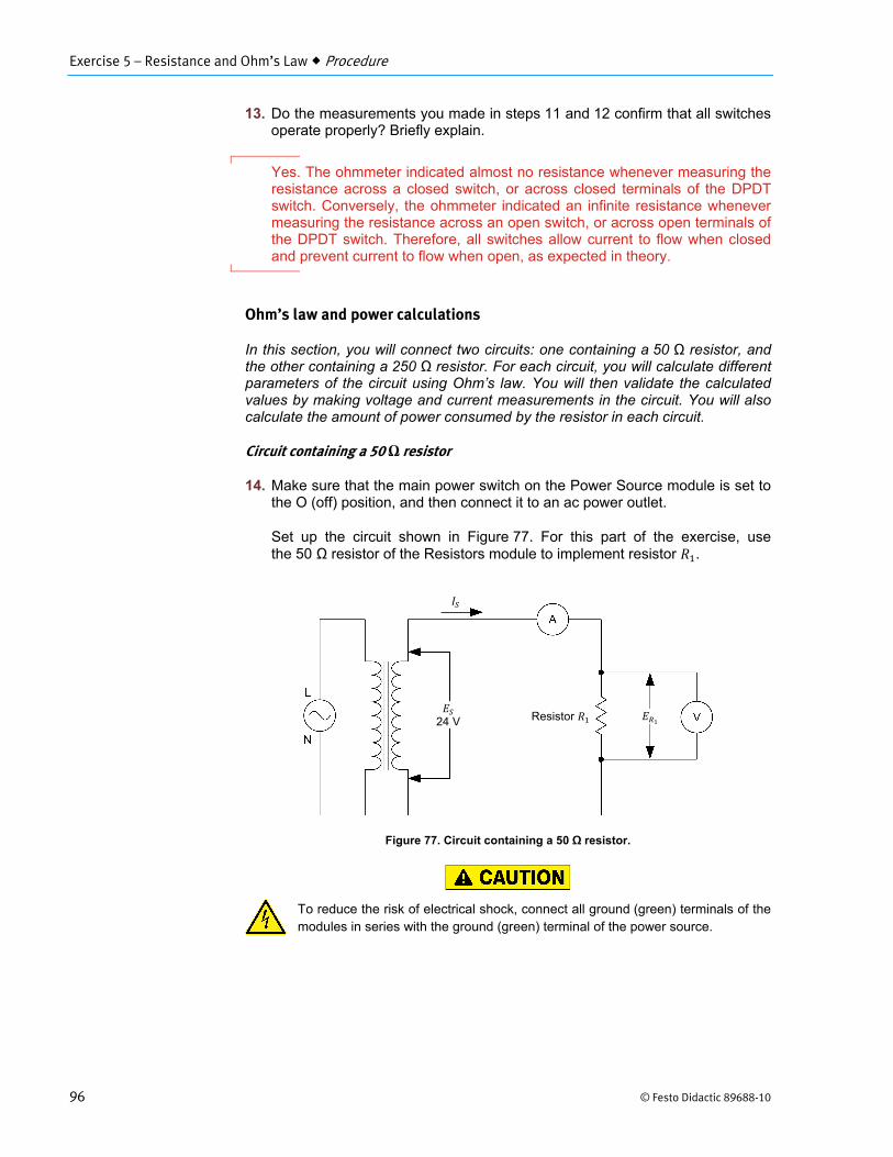
14. Make sure that the main power switch on the Power Source module is set to the O (off) position, and then connect it to an ac power outlet.
Set up the circuit shown in Figure 77. For this part of the exercise, use the 50 Ω resistor of the Resistors module to implement resistor .
Figure 77. Circuit containing a 50 Ω resistor.
To reduce the risk of electrical shock, connect all ground (green) terminals of the modules in series with the ground (green) terminal of the power source.
24 V
Resistor

Exercise 5 – Resistance and Ohm’s Law Procedure
© Festo Didactic 89688-10 97
15. Knowing that the value of the source voltage is equal to 24 V and that the resistance of the resistor is equal to 50 Ω, calculate the intensity of the current that should flow in the circuit.
a Ohm’s law states that:
Calculated current A
24V
50Ω0.48A
16. Turn the power source on.
Select the ammeter function of the multimeter, and then measure the intensity of the current flowing in the circuit. Record the value below.
Measured current A
Measured current 0.51 A
17. Is the current you measured in the previous step virtually equal to the current you calculated in step 15?
Yes No
Yes
18. Select the voltmeter function of the clampmeter, and then measure the voltage across the resistor. Record the value below.
Measured voltage V
Measured voltage 25.01

Exercise 5 – Resistance and Ohm’s Law Procedure
98 © Festo Didactic 89688-10
19. Using the voltage you measured across the resistor and the current flowing in the circuit, calculate the resistance of the resistor.
a Ohm’s law states that:
Calculated resistance Ω
25.01V
0.51A49.0Ω
20. Is the resistance you calculated in the previous step virtually equal to the value you measured in step 4?
Yes No
Yes
21. Using the circuit parameters you calculated in this subsection, find the power dissipated by the 50 Ω resistor. Record the value below.
a Power can be calculated using the following equation:
Calculated power W
Calculated power 11.3W
22. Is the power dissipated by the 50 Ω resistor lower than the power rating of the resistor indicated on the front panel of the Resistors module, thus confirming that the resistor rating is not exceeded?
Yes No
Yes
23. Turn the power source off.

Exercise 5 – Resistance and Ohm’s Law Procedure
© Festo Didactic 89688-10 99
Circuit containing a 250 Ω resistor
24. In the circuit of Figure 77, replace the 50 Ω resistor with the 250 Ω resistor.
25. Knowing the ac power source voltage (24 V) and the resistance (250 Ω) of the resistor, calculate the current flowing in the circuit.
Calculated current A
Current is calculated as follows:
24V
250Ω0.096A
26. Turn the power source on.
Using the ammeter, measure the intensity of the current flowing in the circuit. Record the value below.
Measured current A
Measured current 0.101
27. Is the current you measured in the previous step virtually equal to the current you calculated in step 25?
Yes No
Yes
28. Using the current you measured in step 26 and the resistance of the resistor (250 Ω), calculate the voltage across the resistor.
a Ohm’s law states that:
Calculated voltage V
0.101A 250Ω 25.3V

Exercise 5 – Resistance and Ohm’s Law Procedure
100 © Festo Didactic 89688-10
29. Using a voltmeter, measure the voltage across the resistor. Record the value below.
Measured voltage V
Measured voltage = 25.8 V
30. Is the voltage across the resistor you measured in the previous step virtually equal to the voltage you calculated in step 28?
Yes No
Yes
31. Using the circuit parameters you calculated in this subsection, find the power dissipated by the 250 Ω resistor. Record the value below.
a Power can be calculated using the following equation:
Calculated power W
2.4 W
32. Is the amount of power dissipated by the 250 Ω resistor lower than the power rating of the resistor indicated on the front panel of the Resistors module, thus confirming that the resistor rating is not exceeded?
Yes No
Yes
33. Turn the power source off.
34. Do the measurements and calculations you made in this section confirm Ohm’s law? Briefly explain.
Yes, all values calculated using Ohm’s law were validated by circuit measurements. This confirms the relationships between voltage, current, and resistance expressed in Ohm’s law.
Exercise 5 – Resistance and Ohm’s Law Procedure
© Festo Didactic 89688-10 101
Testing continuity of a circuit using a test light
In this section, you will connect a circuit containing two indicator lights controlled using a toggle switch and a push-button switch. You will state the conditions for continuity to be present between the different pairs of terminals indicated on the circuit. You will then connect a test light circuit and use it to confirm the validity of your statements on the continuity between the different terminals.
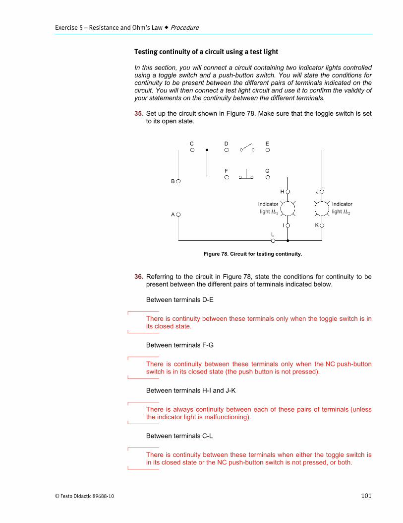
35. Set up the circuit shown in Figure 78. Make sure that the toggle switch is set to its open state.
Figure 78. Circuit for testing continuity.
36. Referring to the circuit in Figure 78, state the conditions for continuity to be present between the different pairs of terminals indicated below.
Between terminals D-E
There is continuity between these terminals only when the toggle switch is in its closed state.
Between terminals F-G
There is continuity between these terminals only when the NC push-button switch is in its closed state (the push button is not pressed).
Between terminals H-I and J-K
There is always continuity between each of these pairs of terminals (unless the indicator light is malfunctioning).
Between terminals C-L
There is continuity between these terminals when either the toggle switch is in its closed state or the NC push-button switch is not pressed, or both.
A
B
C D E
F G
H
I
J
K
Indicator
light 2
Indicator
light 1
L

Exercise 5 – Resistance and Ohm’s Law Procedure
102 © Festo Didactic 89688-10
37. Connect the test light circuit shown in Figure 79. Use the remaining indicator light to implement the test light.
Figure 79. Test light circuit for measuring continuity.
38. Turn the power source on.
Connect the test light circuit shown in Figure 79 to each pair of terminals indicated in step 36. For each pair of terminals, validate the conditions you stated for continuity to be present between each pair of terminals.
39. Were you able to validate all the conditions stated in step 36 for continuity to be present between the different pairs of terminals in Figure 78?
Yes No
Yes
40. Do your observations indicate that the test light circuit in Figure 79 can be used to replace an ohmmeter for continuity testing?
Yes No
41. Turn off the power source and the measuring instruments.
Disconnect your circuit.
Return the leads to their storage location.
Test light
24 V
1
2
0 V

Exercise 5 – Resistance and Ohm’s Law Conclusion
© Festo Didactic 89688-10 103
In this exercise, you became familiar with the notion of resistance, and learned how to measure this parameter using an ohmmeter. You were introduced to Ohm’s law, and learned to calculate voltage, current, and resistance in electrical circuits. You also learned the concepts of conductors, insulators, short circuits, open circuits, and continuity in electrical circuits. You also became familiar with the concept of power. Finally, you were introduced to the Resistors module.
1. Define what resistance is.
The resistance of a material represents the opposition of the material to current flow.
2. You need to measure the resistance of a circuit. Briefly explain which instrument is required, and how to connect it.
To measure the resistance of a circuit, it is necessary to use an ohmmeter. The ohmmeter is connected across the circuit. It is important to make sure that the power source is removed from the circuit before connecting the ohmmeter.
3. What is continuity? How is it possible to test the continuity between two points in an electrical circuit?
Continuity between two points in a circuit simply indicates that electrical current can flow between the two points and therefore that the circuit is not open. It is possible to test the continuity between two points by measuring the resistance between these two points using an ohmmeter. If the measured resistance is anything but infinite, there is continuity.
4. Define what power is.
Power is defined as the rate at which work is produced.
CONCLUSION
REVIEW QUESTIONS

Exercise 5 – Resistance and Ohm’s Law Review Questions
104 © Festo Didactic 89688-10
5. Consider the circuit shown in Figure 80. Knowing that the power source voltage is equal to 100 V and that the resistance of the indicator light is equal to 80 Ω, calculate the current flowing in the circuit as well as the power supplied by the power source.
Figure 80. Circuit for review question 5.
100V
80Ω1.25A
100V 1.25A 125W
100 V
Power source
Indicator light 80 Ω


© Festo Didactic 89688-10 363
Bibliography
Boylestad, Robert L., Introductory Circuit Analysis, 11th ed., Upper Saddle River: Prentice Hall, 2006, ISBN 978-0131730441.
Herman, Stephen L. and Sparkman, Bennie L., Electricity & Controls for HVAC/R, 6th ed., Clifton Park: Delmar Cengage Learning, 2010, ISBN 978-1-4354-8427-6.
Miller, Rex and Miller, Mark, Electricity and Electronics for HVAC, 1st ed., New York: McGraw-Hill Companies, 2007, ISBN 0-07-154270-1.
Wildi, Theodore, Electrical Machines, Drives, and Power Systems, 6th ed., Upper Saddle River: Prentice Hall, 2005, IS 978-0131776913.