Embed Size (px)
Citation preview
1SYSTEMS PROTECTORS ed. 001-DP-ENG
REFRIGERATING SYSTEMS PROTECTORSHANDBOOK

3SYSTEMS PROTECTORS ed. 001-DP-ENG
FROM QUALITY OUR NATURAL DEVELOPMENTAchieved the goal of fifty years working in the industry of Refrigeration and Air Conditioning, Castel Quality Range of Products is well known and highly appreciated all over the world. Quality is the main issue of our Company and it has a special priority, in every step, all along the production cycle. UNI EN ISO 9001:2008, issued by ICIM, certifies the Quality System of the Factory. Moreover Castel Products count a number of certifications in conformity with EEC Directives and with European and American Quality Approval.We produce on high tech machinery and updated automatic production lines, operating in conformity with the safety and environment standards currently enforced.Castel offers to the Refrigeration and Air Conditioning Market and to the Manufacturers fully tested products suitable with HCFC and HFC Refrigerants currently used in the Refrigeration & Air Conditioning Industry.
INDICE
Liquid & moisture/liquid indicatorsHermetic solid core filter driersHermetic solid core filter driers with sight glass Hermetic solid core bi-flow filter driersReplaceable solid core filter driersReplaceable mechanical block filtersStrainers
09142732354146

4SYSTEMS PROTECTORSed. 001-DP-ENG
5SYSTEMS PROTECTORS ed. 001-DP-ENG
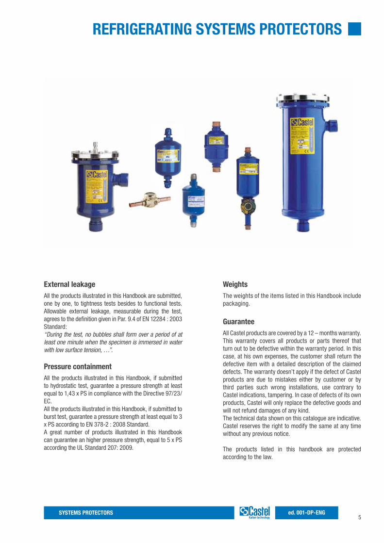
REFRIGERATING SYSTEMS PROTECTORS
External leakageAll the products illustrated in this Handbook are submitted, one by one, to tightness tests besides to functional tests. Allowable external leakage, measurable during the test, agrees to the definition given in Par. 9.4 of EN 12284 : 2003 Standard:“During the test, no bubbles shall form over a period of at least one minute when the specimen is immersed in water with low surface tension, …”.
Pressure containmentAll the products illustrated in this Handbook, if submitted to hydrostatic test, guarantee a pressure strength at least equal to 1,43 x PS in compliance with the Directive 97/23/EC.All the products illustrated in this Handbook, if submitted to burst test, guarantee a pressure strength at least equal to 3 x PS according to EN 378-2 : 2008 Standard.A great number of products illustrated in this Handbook can guarantee an higher pressure strength, equal to 5 x PS according the UL Standard 207: 2009.
WeightsThe weights of the items listed in this Handbook include packaging.
GuaranteeAll Castel products are covered by a 12 – months warranty. This warranty covers all products or parts thereof that turn out to be defective within the warranty period. In this case, at his own expenses, the customer shall return the defective item with a detailed description of the claimed defects. The warranty doesn’t apply if the defect of Castel products are due to mistakes either by customer or by third parties such wrong installations, use contrary to Castel indications, tampering. In case of defects of its own products, Castel will only replace the defective goods and will not refund damages of any kind.The technical data shown on this catalogue are indicative. Castel reserves the right to modify the same at any time without any previous notice.
The products listed in this handbook are protected according to the law.

6SYSTEMS PROTECTORSed. 001-DP-ENG
7SYSTEMS PROTECTORS ed. 001-DP-ENG
Among contaminating agents causing serious damages to refrigerating systems, moisture plays a major role. Its presence, even possible in the refrigerating system, is due to many factors: • inadequate or insufficiently prolonged vacuum before refrigerant charging• oil used for topping up remained exposed to air humidity• refrigerant used for subsequent additions contained in non dried vessels• sealing defects especially in systems not designed for operation at low temperaturesHigh temperatures combined with humidity give rise to complex phenomena enhancing acid formation both in lubricating oil and refrigerant.Oil organic acids react with metal and favor the formation of sludge, which are viscous clots consisting of insoluble metal salts and large molecules of polymerized oil.Sludge affects the lubrication of the moving elements of the compressor, can clog valves and filters and cause serious damages.Acids, especially hydrofluoric acid, produced by the hydrolysis of the fluorinated refrigerant (in compressors iron and aluminum act as catalysts) are particularly corrosive.Acids etch metal surfaces with the consequent formation of crystal salts, which stick to surfaces and affect the total heat exchange coefficient in the condenser and in the evaporator.In the sealed and semi-sealed groups, these salts damage the windings of electric motors as in these groups cold gas cools windings through direct contact.On the other hand, water solubility in refrigerants in a liquid phase, is quite reduced, especially at low temperatures. As a consequence, when in the system water exceeds the very low limits of solubility admitted at low temperature,
excess water turns into ice, and blocks expansion valves and capillaries either partially or totally.Consequently, refrigerating plants must be equipped with a filter drier on the liquid line and types available on the market are essentially two: molecular sieve driers and solid core driers.In molecular sieve driers, with a charge constituted by non-agglomerated products, the dehydrating mass is pressed in between two fine steel mesh disks, or two filtering disks of various materials, kept in place by a spring.In solid core driers, dehydrating and deacidifying products with binders constitute the block. Water adsorption combines with the neutralization of acids that may be present in the refrigerant, and with a strong filtering action.Castel have planned either its production lines of hermetic driers on this second solution that avoid any risk of abrasion of the charge and consequently the making of powder and permit to put the filter in any position inside the refrigerating system.It is always advisable to install a moisture indicator downstream the filter, which will show the refrigerant moisture and, consequently, the degree of efficiency of the filter.The dehydrating capacity of Castel drier is relative to the charge of refrigerant and not to the refrigeration potential of the plant. As a matter of fact, for the same refrigerant potential and for the same type of refrigerant fluid, there can be different refrigerant charges according to the type, design and working conditions of the plant as well as to the shutter degree.The data shown in the following tables are deduced from the test results of the present Castel production.It is important to note in the case of a high oil level in the circuit (> 5%) the data shown in the tables will be reduced considerably.
DEHYDRATION OF REFRIGERANTS

8SYSTEMS PROTECTORSed. 001-DP-ENG
9SYSTEMS PROTECTORS ed. 001-DP-ENG
LIQUID INDICATORS & MOISTURE-LIQUID INDICATORS
Approved by Underwriters Laboratories Inc.
by Underwriters Laboratories Inc. of the United States according to UL 207 Standard.
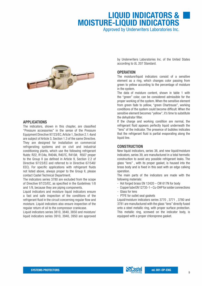
OPERATIONThe moisture/liquid indicators consist of a sensitive element as a ring, which changes color passing from green to yellow according to the percentage of moisture in the system.The data of moisture content, shown in table 1 with the “green” color, can be considered admissible for the proper working of the system. When the sensitive element from green fade to yellow, “green Chartreuse”, working conditions of the system could become difficult. When the sensitive element becomes “yellow”, it’s time to substitute the dehydrator filter.If the charge and working condition are normal, the refrigerant fluid appears perfectly liquid underneath the “lens” of the indicator. The presence of bubbles indicates that the refrigerant fluid is partial evaporating along the liquid line.
CONSTRUCTIONNew liquid indicators, series 38, and new liquid/moisture indicators, series 39, are manufactured in a total hermetic construction to avoid any possible refrigerant leaks. The glass “lens” , with its proper gasket, is housed into the brass body and is fixed in this seat with an edge calking operation.The main parts of the indicators are made with the following materials:- Hot forged brass EN 12420 – CW 617N for body- Copper tube EN 12735-1 – Cu-DHP for solder connections- Glass for lens- PTFE for outlet seal gasketsLiquid/moisture indicators series 3770 , 3771 , 3780 and 3781 are manufactured with the glass “lens” directly fused onto a steel metallic ring, with proper surface protection. This metallic ring, screwed on the indicator body, is equipped with a proper chloroprene gasket.
APPLICATIONSThe indicators, shown in this chapter, are classified “Pressure accessories” in the sense of the Pressure Equipment Directive 97/23/EC, Article 1, Section 2.1.4and are subject of Article 3, Section 1.3 of the same Directive. They are designed for installation on commercial refrigerating systems and on civil and industrial conditioning plants, which use the following refrigerant fluids: R22, R134a, R404A, R407C, R410A; R507 proper to the Group II (as defined in Article 9, Section 2.2 of Directive 97/23/EC and referred to in Directive 67/548/EEC). For specific applications with refrigerant fluids not listed above, always proper to the Group II, please contact Castel Technical Department.The indicators series 3780 are excluded from the scope of Directive 97/23/EC, as specified in the Guidelines 1/8 and 1/9, because they are piping components.Liquid indicators and moisture liquid indicators ensure a fast and safe inspection of the conditions of the refrigerant fluid in the circuit concerning regular flow and moisture. Liquid indicators also ensure inspection of the regular return of oil to the compressor crankcase.Liquid indicators series 3810, 3840, 3850 and moisture/liquid indicators series 3910, 3940, 3950 are approved
10SYSTEMS PROTECTORSed. 001-DP-ENG
INSTALLATIONAt the start-up the color of the sensitive element may be yellow, due to exposure to air humidity and to moisture in the circuit. When the moisture of the refrigerant is brought back to acceptable levels with the dehydrator, the indicator color is once again green. This is evidence that equilibrium has been re-established. In case of persisting yellow, me-asures have to be taken to eliminate moisture. Only when the sensitive element comes back to green, there is eviden-ce that adopted measures were effective. About 12 hours of system operation are required to achieve equilibrium. However, the moisture indication is given normally when the plant is in function and the fluid is flowing.The brazing of indicators with solder connections should be carried out with care, using a low melting point filler
material. In any case, avoid direct contact between the torch flame and the indicator body or glass, which could be damaged and compromise the proper functioning of the indicator.With indicators series 3780 and 3781 it’s necessary to disassemble the ring before starting to braze. NB: the PS declared on table 3 , for saddle type series 3780, is solely referred to the body plus the glass ring (with its O-Ring), assembled by the customer at the correct torque indicated on the product instruction leaflet. The aforesaid declaration doesn’t cover any possible leakage or break-down due to braze the body on the copper tube. The custo-mer is totally responsible for the success of this operation.
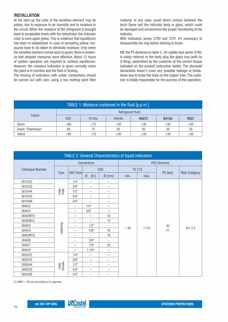
TABLE 2: General Characteristics of liquid indicators
Catalogue Number
Connections PED Directive
Type SAE FlareODS TS [°C]
PS [bar] Risk CategoryØ [in.] Ø [mm] min. max.
3810/22 1/4” – –
– 30 +11045(1)
Art. 3.3
3810/33 3/8” – –3810/44 1/2” – –3810/55 5/8” – –3810/66 3/4” – –3840/2 – 1/4” –3840/3 – 3/8” –3840/M10 – – 103840/M12 – – 123840/4 – 1/2” –3840/5 – 5/8” 163840/M18 – – 183840/6 – 3/4” –3840/7 – 7/8” 223840/9 – 1.1/8” –3850/22 1/4” – –3850/33 3/8” – –3850/44 1/2” – –3850/55 5/8” – –3850/66 3/4” – –
mal
em
ale
sold
erin
gm
ale
fem
ale
TABLE 1: Moisture contained in the fluid [p.p.m.]
ColourRefrigerant fluid
R22 R134a R404A R407C R410A R507
Green <60 <75 <30 <30 <30 <30Green "Chartreuse" 60 75 30 30 30 30Yellow >60 >75 >30 >30 >30 >30
(1): MWP = 435 psi according to UL approval
11SYSTEMS PROTECTORS ed. 001-DP-ENG
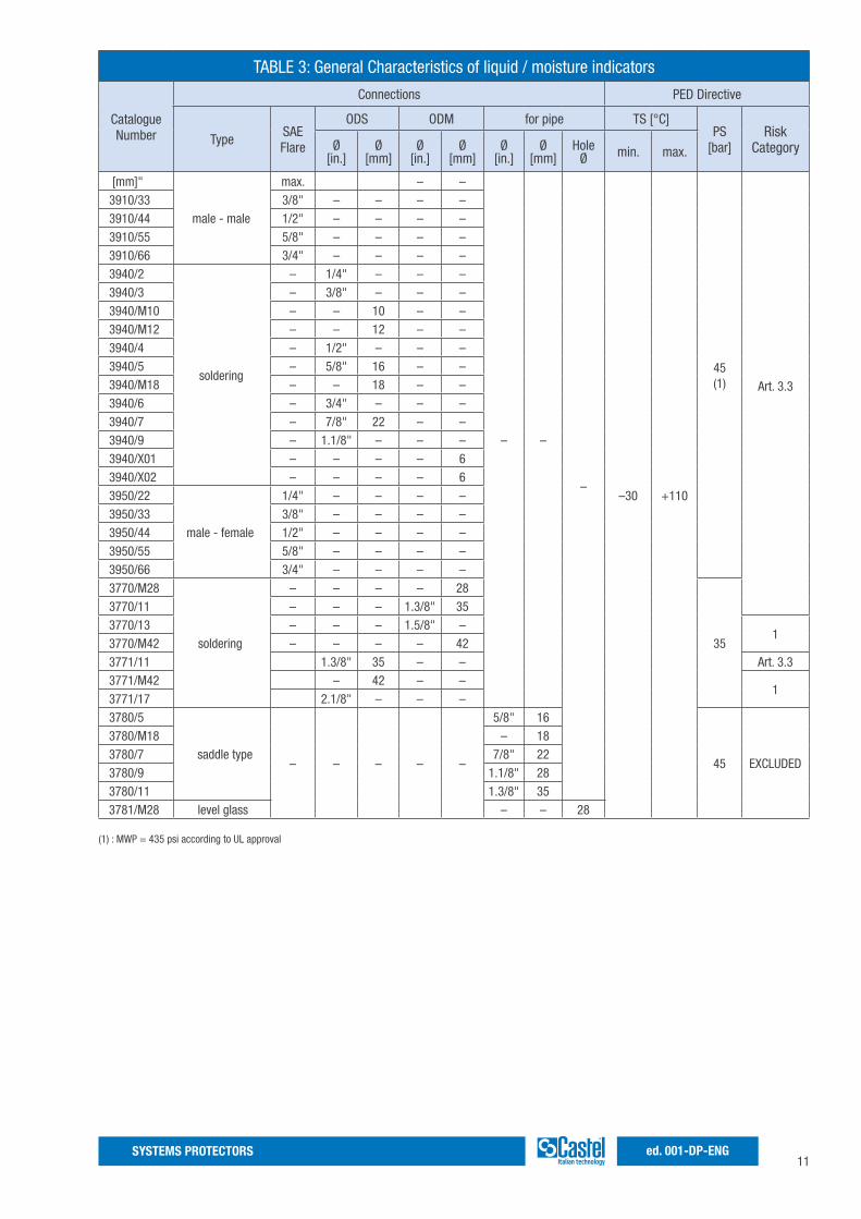
TABLE 3: General Characteristics of liquid / moisture indicators
Catalogue Number
Connections PED Directive
TypeSAE Flare
ODS ODM for pipe TS [°C]PS
[bar]Risk
CategoryØ [in.]
Ø [mm]
Ø [in.]
Ø[mm]
Ø [in.]
Ø [mm]
Hole Ø min. max.
[mm]"
male - male
max. – –
– –
––30 +110
45(1) Art. 3.3
3910/33 3/8" – – – –3910/44 1/2" – – – –3910/55 5/8" – – – –3910/66 3/4" – – – –3940/2
soldering
– 1/4" – – –3940/3 – 3/8" – – –3940/M10 – – 10 – –3940/M12 – – 12 – –3940/4 – 1/2" – – –3940/5 – 5/8" 16 – –3940/M18 – – 18 – –3940/6 – 3/4" – – –3940/7 – 7/8" 22 – –3940/9 – 1.1/8" – – –3940/X01 – – – – 63940/X02 – – – – 63950/22
male - female
1/4" – – – –3950/33 3/8" – – – –3950/44 1/2" – – – –3950/55 5/8" – – – –3950/66 3/4" – – – –3770/M28
soldering
– – – – 28
35
3770/11 – – – 1.3/8" 353770/13 – – – 1.5/8" –
13770/M42 – – – – 423771/11 1.3/8" 35 – – Art. 3.33771/M42 – 42 – –
13771/17 2.1/8" – – –3780/5
saddle type– – – – –
5/8" 16
45 EXCLUDED
3780/M18 – 183780/7 7/8" 223780/9 1.1/8" 283780/11 1.3/8" 353781/M28 level glass – – 28
(1) : MWP = 435 psi according to UL approval
12SYSTEMS PROTECTORSed. 001-DP-ENG
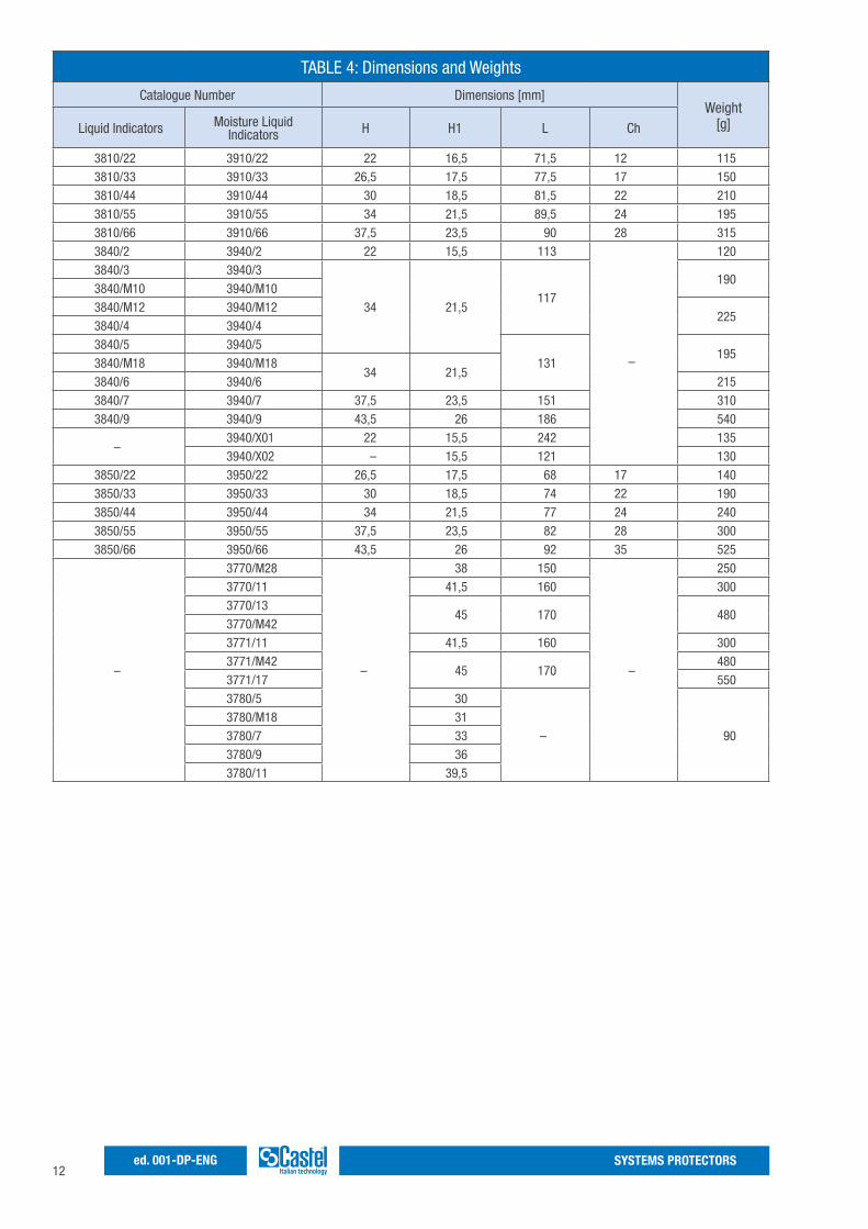
TABLE 4: Dimensions and Weights
Catalogue Number Dimensions [mm]Weight
[g] Liquid Indicators Moisture Liquid Indicators H H1 L Ch
3810/22 3910/22 22 16,5 71,5 12 1153810/33 3910/33 26,5 17,5 77,5 17 1503810/44 3910/44 30 18,5 81,5 22 2103810/55 3910/55 34 21,5 89,5 24 1953810/66 3910/66 37,5 23,5 90 28 3153840/2 3940/2 22 15,5 113
–
1203840/3 3940/3
34 21,5117
1903840/M10 3940/M103840/M12 3940/M12
2253840/4 3940/43840/5 3940/5
131195
3840/M18 3940/M1834 21,5
3840/6 3940/6 2153840/7 3940/7 37,5 23,5 151 3103840/9 3940/9 43,5 26 186 540
–3940/X01 22 15,5 242 1353940/X02 – 15,5 121 130
3850/22 3950/22 26,5 17,5 68 17 1403850/33 3950/33 30 18,5 74 22 1903850/44 3950/44 34 21,5 77 24 2403850/55 3950/55 37,5 23,5 82 28 3003850/66 3950/66 43,5 26 92 35 525
–
3770/M28
–
38 150
–
2503770/11 41,5 160 3003770/13
45 170 4803770/M423771/11 41,5 160 3003771/M42
45 170480
3771/17 5503780/5 30
– 903780/M18 313780/7 333780/9 363780/11 39,5
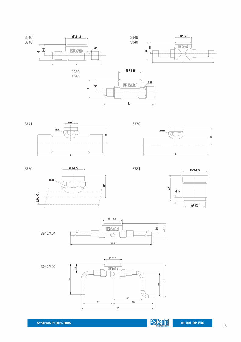
13SYSTEMS PROTECTORS ed. 001-DP-ENG
38103910
3840 3940
3850 3950
3771 3770
3780 3781
3940/X01
3940/X02
14SYSTEMS PROTECTORSed. 001-DP-ENG
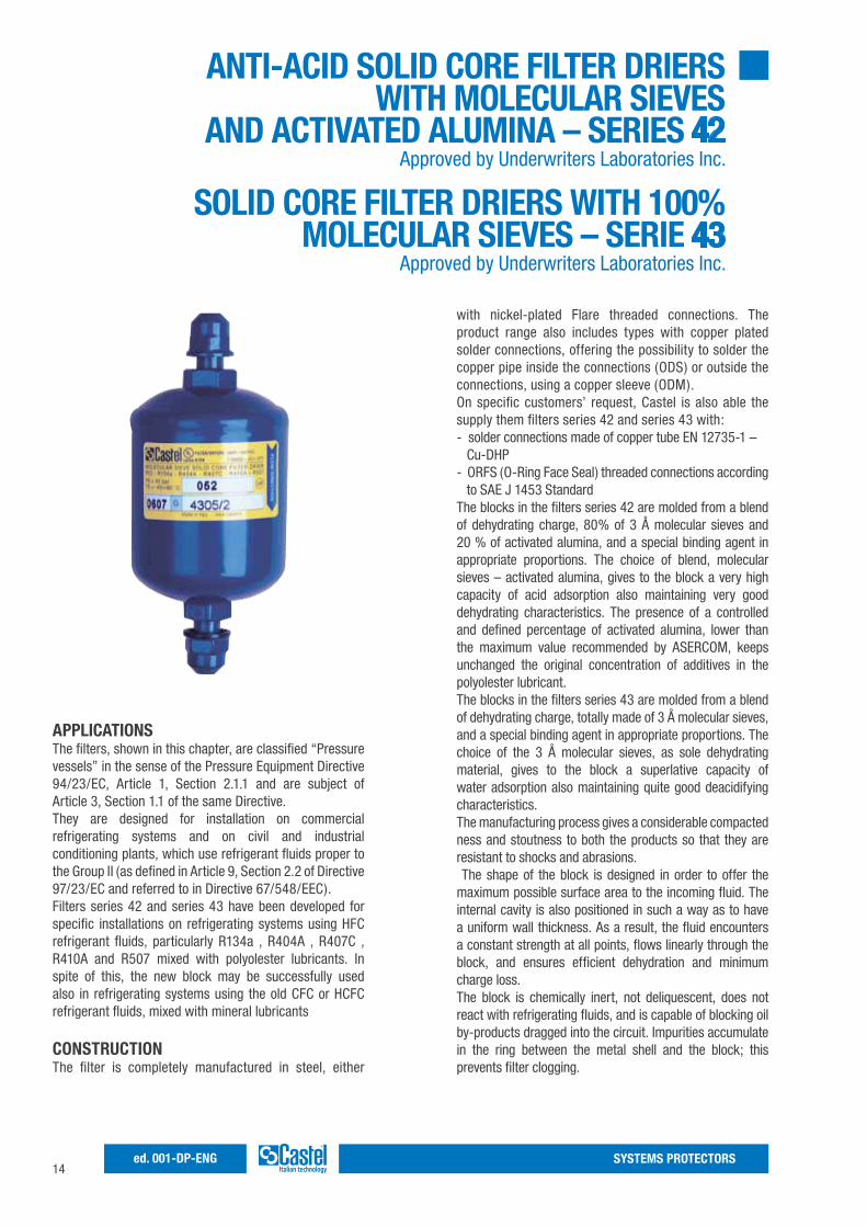
with nickel-plated Flare threaded connections. The product range also includes types with copper plated solder connections, offering the possibility to solder the copper pipe inside the connections (ODS) or outside the connections, using a copper sleeve (ODM).On specific customers’ request, Castel is also able the supply them filters series 42 and series 43 with:- solder connections made of copper tube EN 12735-1 – Cu-DHP- ORFS (O-Ring Face Seal) threaded connections according to SAE J 1453 StandardThe blocks in the filters series 42 are molded from a blend of dehydrating charge, 80% of 3 Å molecular sieves and 20 % of activated alumina, and a special binding agent in appropriate proportions. The choice of blend, molecular sieves – activated alumina, gives to the block a very high capacity of acid adsorption also maintaining very good dehydrating characteristics. The presence of a controlled and defined percentage of activated alumina, lower than the maximum value recommended by ASERCOM, keeps unchanged the original concentration of additives in the polyolester lubricant.The blocks in the filters series 43 are molded from a blend of dehydrating charge, totally made of 3 Å molecular sieves, and a special binding agent in appropriate proportions. The choice of the 3 Å molecular sieves, as sole dehydrating material, gives to the block a superlative capacity of water adsorption also maintaining quite good deacidifying characteristics.The manufacturing process gives a considerable compacted ness and stoutness to both the products so that they are resistant to shocks and abrasions. The shape of the block is designed in order to offer the maximum possible surface area to the incoming fluid. The internal cavity is also positioned in such a way as to have a uniform wall thickness. As a result, the fluid encounters a constant strength at all points, flows linearly through the block, and ensures efficient dehydration and minimum charge loss.The block is chemically inert, not deliquescent, does not react with refrigerating fluids, and is capable of blocking oil by-products dragged into the circuit. Impurities accumulate in the ring between the metal shell and the block; this prevents filter clogging.
APPLICATIONSThe filters, shown in this chapter, are classified “Pressure vessels” in the sense of the Pressure Equipment Directive 94/23/EC, Article 1, Section 2.1.1 and are subject of Article 3, Section 1.1 of the same Directive.They are designed for installation on commercial refrigerating systems and on civil and industrial conditioning plants, which use refrigerant fluids proper to the Group II (as defined in Article 9, Section 2.2 of Directive 97/23/EC and referred to in Directive 67/548/EEC).Filters series 42 and series 43 have been developed for specific installations on refrigerating systems using HFC refrigerant fluids, particularly R134a , R404A , R407C , R410A and R507 mixed with polyolester lubricants. In spite of this, the new block may be successfully used also in refrigerating systems using the old CFC or HCFC refrigerant fluids, mixed with mineral lubricants
CONSTRUCTIONThe filter is completely manufactured in steel, either
ANTI-ACID SOLID CORE FILTER DRIERS WITH MOLECULAR SIEVES
AND ACTIVATED ALUMINA – SERIES 42Approved by Underwriters Laboratories Inc.
SOLID CORE FILTER DRIERS WITH 100% MOLECULAR SIEVES – SERIE 43
Approved by Underwriters Laboratories Inc.
15SYSTEMS PROTECTORS ed. 001-DP-ENG
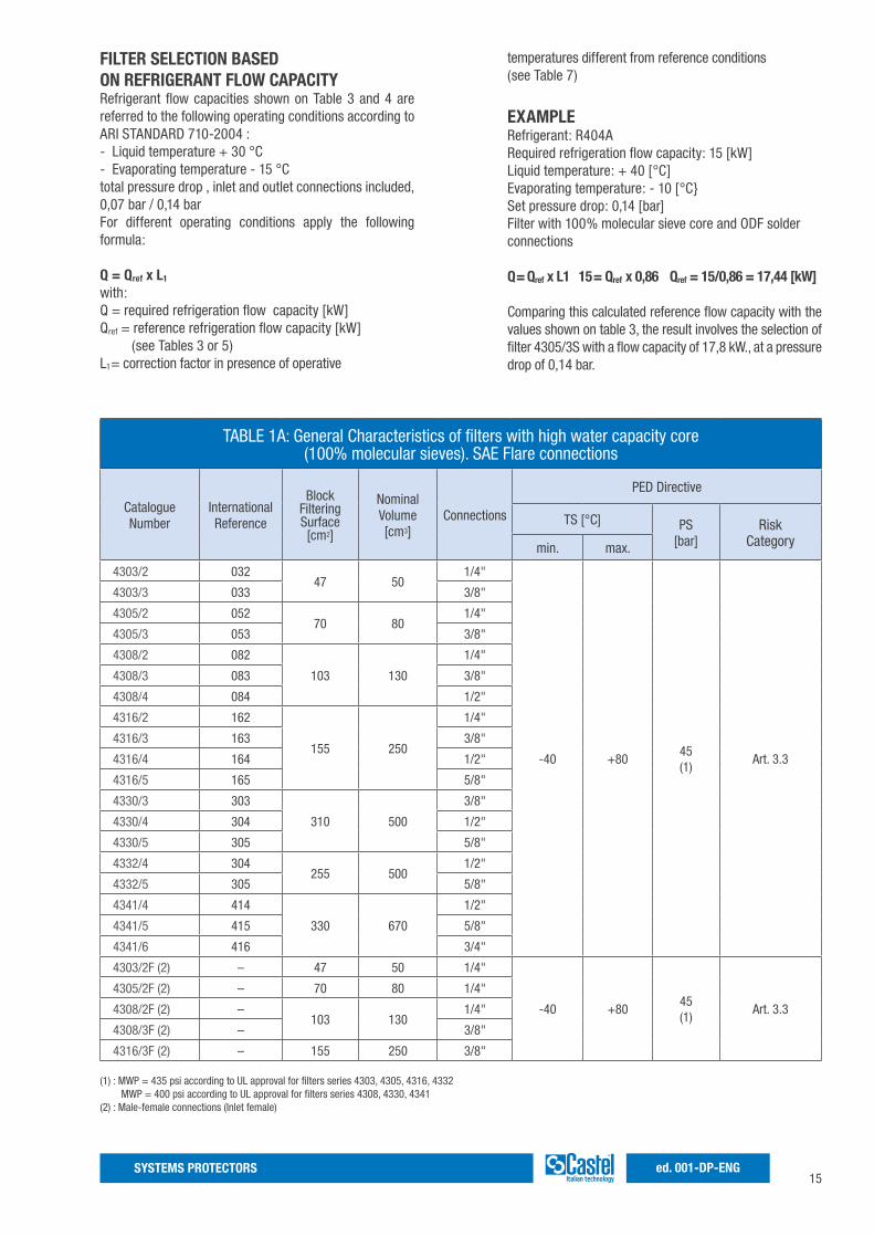
TABLE 1A: General Characteristics of filters with high water capacity core(100% molecular sieves). SAE Flare connections
CatalogueNumber
InternationalReference
Block FilteringSurface[cm2]
NominalVolume[cm3]
Connections
PED Directive
TS [°C] PS [bar]
RiskCategorymin. max.
4303/2 03247 50
1/4"
-40 +8045(1)
Art. 3.3
4303/3 033 3/8"
4305/2 05270 80
1/4"
4305/3 053 3/8"
4308/2 082
103 130
1/4"
4308/3 083 3/8"
4308/4 084 1/2"
4316/2 162
155 250
1/4"
4316/3 163 3/8"
4316/4 164 1/2"
4316/5 165 5/8"
4330/3 303
310 500
3/8"
4330/4 304 1/2"
4330/5 305 5/8"
4332/4 304255 500
1/2"
4332/5 305 5/8"
4341/4 414
330 670
1/2"
4341/5 415 5/8"
4341/6 416 3/4"
4303/2F (2) – 47 50 1/4"
-40 +8045(1)
Art. 3.3
4305/2F (2) – 70 80 1/4"
4308/2F (2) –103 130
1/4"
4308/3F (2) – 3/8"
4316/3F (2) – 155 250 3/8"
temperatures different from reference conditions (see Table 7)
EXAMPLERefrigerant: R404ARequired refrigeration flow capacity: 15 [kW]Liquid temperature: + 40 [°C]Evaporating temperature: - 10 [°C}Set pressure drop: 0,14 [bar]Filter with 100% molecular sieve core and ODF solder connections
Q = Qref x L1 15 = Qref x 0,86 Qref = 15/0,86 = 17,44 [kW]
Comparing this calculated reference flow capacity with the values shown on table 3, the result involves the selection of filter 4305/3S with a flow capacity of 17,8 kW., at a pressure drop of 0,14 bar.
FILTER SELECTION BASED ON REFRIGERANT FLOW CAPACITYRefrigerant flow capacities shown on Table 3 and 4 are referred to the following operating conditions according to ARI STANDARD 710-2004 :- Liquid temperature + 30 °C- Evaporating temperature - 15 °Ctotal pressure drop , inlet and outlet connections included, 0,07 bar / 0,14 barFor different operating conditions apply the following formula:
Q = Qref x L1
with:Q = required refrigeration flow capacity [kW]Qref = reference refrigeration flow capacity [kW] (see Tables 3 or 5)L1= correction factor in presence of operative
(1) : MWP = 435 psi according to UL approval for filters series 4303, 4305, 4316, 4332 MWP = 400 psi according to UL approval for filters series 4308, 4330, 4341 (2) : Male-female connections (Inlet female)
16SYSTEMS PROTECTORSed. 001-DP-ENG
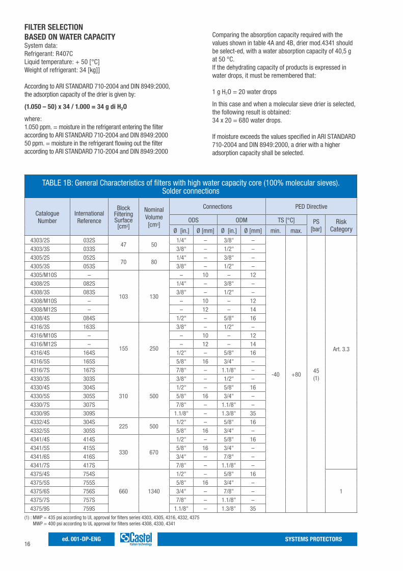
Comparing the absorption capacity required with the values shown in table 4A and 4B, drier mod.4341 should be select-ed, with a water absorption capacity of 40,5 g at 50 °C.If the dehydrating capacity of products is expressed in water drops, it must be remembered that:
1 g H2O = 20 water drops
In this case and when a molecular sieve drier is selected, the following result is obtained:34 x 20 = 680 water drops.
If moisture exceeds the values specified in ARI STANDARD 710-2004 and DIN 8949:2000, a drier with a higher adsorption capacity shall be selected.
FILTER SELECTION BASED ON WATER CAPACITYSystem data:Refrigerant: R407CLiquid temperature: + 50 [°C]Weight of refrigerant: 34 [kg]]
According to ARI STANDARD 710-2004 and DIN 8949:2000, the adsorption capacity of the drier is given by:
(1.050 – 50) x 34 / 1.000 = 34 g di H2O
where:1.050 ppm. = moisture in the refrigerant entering the filteraccording to ARI STANDARD 710-2004 and DIN 8949:200050 ppm. = moisture in the refrigerant flowing out the filteraccording to ARI STANDARD 710-2004 and DIN 8949:2000
TABLE 1B: General Characteristics of filters with high water capacity core (100% molecular sieves).Solder connections
Catalogue Number
InternationalReference
Block FilteringSurface[cm2]
NominalVolume[cm3]
Connections PED Directive
ODS ODM TS [°C] PS [bar]
RiskCategoryØ [in.] Ø [mm] Ø [in.] Ø [mm] min. max.
4303/2S 032S47 50
1/4" – 3/8" –
-40 +8045(1)
Art. 3.3
4303/3S 033S 3/8" – 1/2" –4305/2S 052S
70 801/4" – 3/8" –
4305/3S 053S 3/8" – 1/2" –4305/M10S –
103 130
– 10 – 124308/2S 082S 1/4" – 3/8" –4308/3S 083S 3/8" – 1/2" –4308/M10S – – 10 – 124308/M12S – – 12 – 144308/4S 084S 1/2" – 5/8" 164316/3S 163S
155 250
3/8" – 1/2" –4316/M10S – – 10 – 124316/M12S – – 12 – 144316/4S 164S 1/2" – 5/8" 164316/5S 165S 5/8" 16 3/4" –4316/7S 167S 7/8" – 1.1/8" –4330/3S 303S
310 500
3/8" – 1/2" –4330/4S 304S 1/2" – 5/8" 164330/5S 305S 5/8" 16 3/4" –4330/7S 307S 7/8" – 1.1/8" –4330/9S 309S 1.1/8" – 1.3/8" 354332/4S 304S
225 5001/2" – 5/8" 16
4332/5S 305S 5/8" 16 3/4" –4341/4S 414S
330 670
1/2" – 5/8" 164341/5S 415S 5/8" 16 3/4" –4341/6S 416S 3/4" – 7/8" –4341/7S 417S 7/8" – 1.1/8" –4375/4S 754S
660 1340
1/2" – 5/8" 16
14375/5S 755S 5/8" 16 3/4" –4375/6S 756S 3/4" – 7/8" –4375/7S 757S 7/8" – 1.1/8" –4375/9S 759S 1.1/8" – 1.3/8" 35
(1) : MWP = 435 psi according to UL approval for filters series 4303, 4305, 4316, 4332, 4375 MWP = 400 psi according to UL approval for filters series 4308, 4330, 4341
17SYSTEMS PROTECTORS ed. 001-DP-ENG
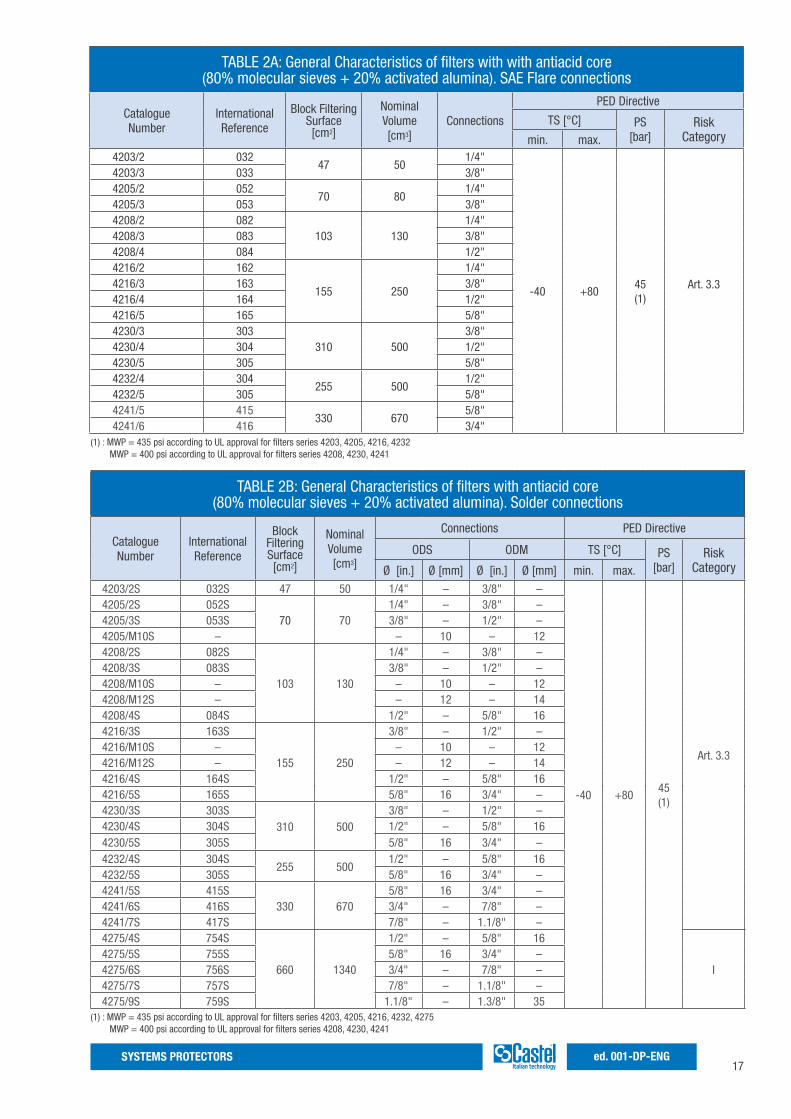
TABLE 2A: General Characteristics of filters with with antiacid core(80% molecular sieves + 20% activated alumina). SAE Flare connections
Catalogue Number
InternationalReference
Block FilteringSurface[cm2]
NominalVolume[cm3]
Connections
PED Directive
TS [°C] PS [bar]
RiskCategorymin. max.
4203/2 03247 50
1/4"
-40 +8045(1)
Art. 3.3
4203/3 033 3/8"4205/2 052
70 801/4"
4205/3 053 3/8"4208/2 082
103 1301/4"
4208/3 083 3/8"4208/4 084 1/2"4216/2 162
155 250
1/4"4216/3 163 3/8"4216/4 164 1/2"4216/5 165 5/8"4230/3 303
310 5003/8"
4230/4 304 1/2"4230/5 305 5/8"4232/4 304
255 5001/2"
4232/5 305 5/8"4241/5 415
330 6705/8"
4241/6 416 3/4"(1) : MWP = 435 psi according to UL approval for filters series 4203, 4205, 4216, 4232 MWP = 400 psi according to UL approval for filters series 4208, 4230, 4241
TABLE 2B: General Characteristics of filters with antiacid core(80% molecular sieves + 20% activated alumina). Solder connections
Catalogue Number
InternationalReference
Block FilteringSurface[cm2]
NominalVolume[cm3]
Connections PED Directive
ODS ODM TS [°C] PS [bar]
RiskCategoryØ [in.] Ø [mm] Ø [in.] Ø [mm] min. max.
4203/2S 032S 47 50 1/4" – 3/8" –
-40 +8045(1)
Art. 3.3
4205/2S 052S70 70
1/4" – 3/8" –4205/3S 053S 3/8" – 1/2" –4205/M10S – – 10 – 124208/2S 082S
103 130
1/4" – 3/8" –4208/3S 083S 3/8" – 1/2" –4208/M10S – – 10 – 124208/M12S – – 12 – 144208/4S 084S 1/2" – 5/8" 164216/3S 163S
155 250
3/8" – 1/2" –4216/M10S – – 10 – 124216/M12S – – 12 – 144216/4S 164S 1/2" – 5/8" 164216/5S 165S 5/8" 16 3/4" –4230/3S 303S
310 5003/8" – 1/2" –
4230/4S 304S 1/2" – 5/8" 164230/5S 305S 5/8" 16 3/4" –4232/4S 304S
255 5001/2" – 5/8" 16
4232/5S 305S 5/8" 16 3/4" –4241/5S 415S
330 6705/8" 16 3/4" –
4241/6S 416S 3/4" – 7/8" –4241/7S 417S 7/8" – 1.1/8" –4275/4S 754S
660 1340
1/2" – 5/8" 16
I4275/5S 755S 5/8" 16 3/4" –4275/6S 756S 3/4" – 7/8" –4275/7S 757S 7/8" – 1.1/8" –4275/9S 759S 1.1/8" – 1.3/8" 35
(1) : MWP = 435 psi according to UL approval for filters series 4203, 4205, 4216, 4232, 4275 MWP = 400 psi according to UL approval for filters series 4208, 4230, 4241

18SYSTEMS PROTECTORSed. 001-DP-ENG
TABLE 3: Refrigerant Flow Capacity of filters with high water capacity core
CatalogueNumber
Refrigerant Flow Capacity,pressure drop 0,07 bar (1)
[kW]
Refrigerant Flow Capacity,pressure drop 0,14 bar (1)
[kW]
4303/26,4 7,0 4,6 7,0 6,8 4,4 7,7 8,4 5,5 8,4 8,1 5,3
4303/2F4303/2S 7,9 8,6 5,7 8,6 8,3 5,5 9,4 10,3 6,8 10,4 10,0 6,54303/3 14,7 16,1 10,6 16,2 15,6 10,2 17,7 19,3 12,7 19,4 18,7 12,24303/3S 18,6 20,3 13,4 20,4 19,7 12,9 22,3 24,4 16,1 24,5 23,6 15,44305/2
6,6 7,2 4,7 7,2 7,0 4,6 8,6 9,4 6,2 9,4 9,1 5,94305/2F4305/2S 8,1 8,9 5,9 8,9 8,6 5,6 10,6 11,6 7,6 11,6 11,2 7,34305/3 15,2 16,6 10,9 16,7 16,1 10,5 19,7 21,6 14,2 21,7 20,9 13,74305/3S
19,2 21,0 13,8 21,1 20,3 13,3 25,0 27,3 18,0 27,4 26,5 17,34305/M10S4308/2
6,9 7,5 4,9 7,5 7,3 4,8 8,9 9,8 6,4 9,8 9,4 6,24308/2F4308/2S 8,4 9,2 6,1 9,2 8,9 5,8 10,9 12,0 7,9 12,0 11,6 7,64308/3
17,8 19,5 12,9 19,6 18,9 12,4 23,2 25,4 16,7 25,5 24,6 16,14308/3F4308/3S
22,6 24,7 16,3 24,8 23,9 15,7 29,4 32,1 21,2 32,2 31,1 20,44308/M10S4308/M12S 28,6 31,3 20,6 31,4 30,3 19,8 37,2 40,7 26,8 40,9 39,4 25,84308/4 23,7 25,9 17,1 26,0 25,1 16,4 30,8 33,7 22,2 33,8 32,6 21,34308/4S 28,6 31,3 20,6 31,4 30,3 19,8 37,2 40,7 26,8 40,9 39,4 25,84316/2 6,9 7,5 4,9 7,5 7,3 4,8 9,3 10,1 6,7 10,2 9,8 6,44316/3
19,5 21,3 14,0 21,4 20,6 13,5 26,3 28,8 18,9 28,9 27,9 18,24316/3F4316/3S
24,3 26,6 17,5 26,7 25,8 16,9 32,9 35,9 23,7 36,1 34,8 22,84316/M10S4316/M12S 33,8 36,9 24,3 37,0 35,8 23,4 45,6 49,8 32,8 50,0 48,3 31,64316/4 27,9 30,5 20,1 30,6 29,6 19,3 37,7 41,2 27,1 41,3 39,9 26,14316/4S 33,8 36,9 24,3 37,0 35,8 23,4 45,6 49,8 32,8 50,0 48,3 31,64316/5 37,1 40,6 26,8 40,8 39,3 25,7 50,2 54,8 36,1 55,0 53,1 34,74316/5S 44,6 48,7 32,1 48,9 47,2 30,9 60,2 65,7 43,3 66,0 63,7 41,74316/7S 47,2 51,6 34,0 51,8 50,0 32,7 63,7 69,7 45,9 69,9 67,5 44,24330/3 21,4 23,4 15,4 23,5 22,7 14,8 28,9 31,6 20,8 31,7 30,6 20,04330/3S 26,8 29,3 19,3 29,4 28,4 18,6 36,2 39,6 26,1 39,7 38,3 25,14330/4 30,6 33,4 22,0 33,5 32,4 21,2 41,3 45,1 29,7 45,3 43,7 28,64330/4S 37,0 40,4 26,6 40,6 39,1 25,6 49,9 54,5 35,9 54,8 52,8 34,64330/5 38,3 41,9 27,6 42,1 40,6 26,6 51,8 56,6 37,3 56,8 54,8 35,94330/5S 46,1 50,4 33,2 50,6 48,8 32,0 62,3 68,0 44,8 68,3 65,9 43,14330/7S
48,7 53,2 35,1 53,4 51,6 33,7 65,7 71,8 47,3 72,1 69,6 45,54330/9S4332/4 33,2 36,3 23,9 36,4 35,2 23,0 46,5 50,8 33,5 51,0 49,2 32,24332/4S 40,1 43,8 28,9 44,0 42,4 27,8 56,1 61,3 40,4 61,6 59,4 38,94332/5 39,4 43,1 28,4 43,3 41,8 27,3 55,2 60,3 39,8 60,6 58,5 38,34332/5S 47,7 52,1 34,3 52,3 50,5 33,0 66,7 72,9 48,1 73,2 70,7 46,24341/4 34,2 37,4 24,6 37,5 36,2 23,7 51,3 56,1 37,0 56,3 54,4 35,64341/4S 40,8 44,6 29,4 44,8 43,2 28,3 61,2 66,9 44,1 67,2 64,8 42,44341/5 40,4 44,2 29,1 44,4 42,8 28,0 60,7 66,3 43,7 66,6 64,2 42,04341/5S 49,0 53,5 35,3 53,7 51,8 33,9 73,4 80,3 52,9 80,6 77,8 50,94341/6
66,4 72,6 47,8 72,9 70,3 46,0 99,6 108,9 71,8 109,3 105,5 69,04341/6S4341/7S 73,4 80,2 52,9 80,5 77,7 50,8 110,1 120,3 79,3 120,8 116,6 76,34375/4S 52,8 57,7 38,0 57,9 55,9 36,6 79,2 86,6 57,0 86,9 83,9 54,94375/5S 53,9 58,9 38,8 59,1 57,1 37,3 80,8 88,4 58,2 88,7 85,6 56,04375/6S 79,7 87,1 57,4 87,4 84,4 55,2 119,5 130,7 86,1 131,2 126,6 82,84375/7S 91,8 100,3 66,1 100,7 97,2 63,6 137,7 150,5 99,1 151,1 145,8 95,44375/9S 95,4 104,3 68,7 104,7 101,1 66,1 143,2 156,5 103,1 157,1 151,6 99,2
R134
a
R22
R404
AR5
07
R407
C
R410
A
R507
(1) : Maximum values of the refrigerant flow capacity at which the drier can be used when fluid dehydration is not the a major problem, provided that the original moisture is limited before the installation of the drier. The maximum refrigerant flow capacities are referred to a total pressure drop of 0,07 bar / 0,14 bar , inlet and outlet connections included, (according to ARI STANDARD 710-2004 - with liquid temperature at + 30 °C and evaporating temperature at - 15 °C )
R134
a
R22
R404
AR5
07
R407
C
R410
A
R507
19SYSTEMS PROTECTORS ed. 001-DP-ENG
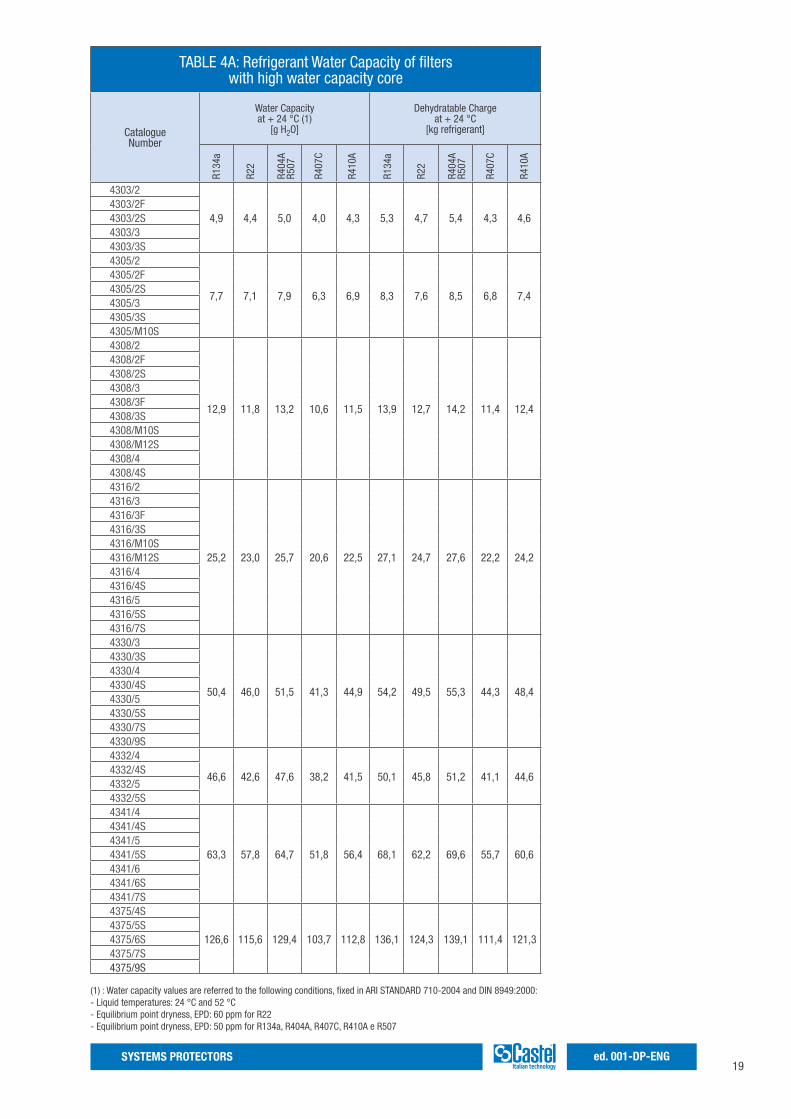
TABLE 4A: Refrigerant Water Capacity of filters with high water capacity core
CatalogueNumber
Water Capacityat + 24 °C (1)
[g H2O]
Dehydratable Chargeat + 24 °C
[kg refrigerant]
4303/2
4,9 4,4 5,0 4,0 4,3 5,3 4,7 5,4 4,3 4,64303/2F4303/2S4303/34303/3S4305/2
7,7 7,1 7,9 6,3 6,9 8,3 7,6 8,5 6,8 7,4
4305/2F4305/2S4305/34305/3S4305/M10S4308/2
12,9 11,8 13,2 10,6 11,5 13,9 12,7 14,2 11,4 12,4
4308/2F4308/2S4308/34308/3F4308/3S4308/M10S4308/M12S4308/44308/4S4316/2
25,2 23,0 25,7 20,6 22,5 27,1 24,7 27,6 22,2 24,2
4316/34316/3F4316/3S4316/M10S4316/M12S4316/44316/4S4316/54316/5S4316/7S4330/3
50,4 46,0 51,5 41,3 44,9 54,2 49,5 55,3 44,3 48,4
4330/3S4330/44330/4S4330/54330/5S4330/7S4330/9S4332/4
46,6 42,6 47,6 38,2 41,5 50,1 45,8 51,2 41,1 44,64332/4S4332/54332/5S4341/4
63,3 57,8 64,7 51,8 56,4 68,1 62,2 69,6 55,7 60,6
4341/4S4341/54341/5S4341/64341/6S4341/7S4375/4S
126,6 115,6 129,4 103,7 112,8 136,1 124,3 139,1 111,4 121,34375/5S4375/6S4375/7S4375/9S
(1) : Water capacity values are referred to the following conditions, fixed in ARI STANDARD 710-2004 and DIN 8949:2000:- Liquid temperatures: 24 °C and 52 °C- Equilibrium point dryness, EPD: 60 ppm for R22- Equilibrium point dryness, EPD: 50 ppm for R134a, R404A, R407C, R410A e R507
R134
a
R22
R404
AR5
07
R407
C
R410
A
R134
a
R22
R404
AR5
07
R407
C
R410
A
20SYSTEMS PROTECTORSed. 001-DP-ENG
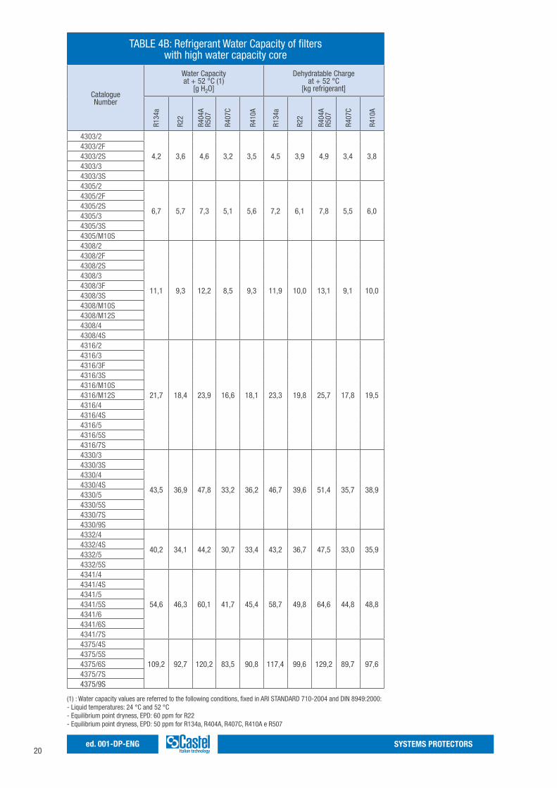
TABLE 4B: Refrigerant Water Capacity of filters with high water capacity core
CatalogueNumber
Water Capacityat + 52 °C (1)
[g H2O]
Dehydratable Chargeat + 52 °C
[kg refrigerant]
4303/2
4,2 3,6 4,6 3,2 3,5 4,5 3,9 4,9 3,4 3,84303/2F4303/2S4303/34303/3S4305/2
6,7 5,7 7,3 5,1 5,6 7,2 6,1 7,8 5,5 6,0
4305/2F4305/2S4305/34305/3S4305/M10S4308/2
11,1 9,3 12,2 8,5 9,3 11,9 10,0 13,1 9,1 10,0
4308/2F4308/2S4308/34308/3F4308/3S4308/M10S4308/M12S4308/44308/4S4316/2
21,7 18,4 23,9 16,6 18,1 23,3 19,8 25,7 17,8 19,5
4316/34316/3F4316/3S4316/M10S4316/M12S4316/44316/4S4316/54316/5S4316/7S4330/3
43,5 36,9 47,8 33,2 36,2 46,7 39,6 51,4 35,7 38,9
4330/3S4330/44330/4S4330/54330/5S4330/7S4330/9S4332/4
40,2 34,1 44,2 30,7 33,4 43,2 36,7 47,5 33,0 35,94332/4S4332/54332/5S4341/4
54,6 46,3 60,1 41,7 45,4 58,7 49,8 64,6 44,8 48,8
4341/4S4341/54341/5S4341/64341/6S4341/7S4375/4S
109,2 92,7 120,2 83,5 90,8 117,4 99,6 129,2 89,7 97,64375/5S4375/6S4375/7S4375/9S
(1) : Water capacity values are referred to the following conditions, fixed in ARI STANDARD 710-2004 and DIN 8949:2000:- Liquid temperatures: 24 °C and 52 °C- Equilibrium point dryness, EPD: 60 ppm for R22- Equilibrium point dryness, EPD: 50 ppm for R134a, R404A, R407C, R410A e R507
R134
a
R22
R404
AR5
07
R407
C
R410
A
R134
a
R22
R404
AR5
07
R407
C
R410
A
21SYSTEMS PROTECTORS ed. 001-DP-ENG
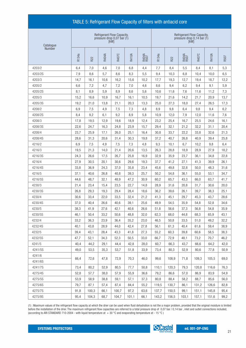
(1) : Maximum values of the refrigerant flow capacity at which the drier can be used when fluid dehydration is not the a major problem, provided that the original moisture is limited before the installation of the drier. The maximum refrigerant flow capacities are referred to a total pressure drop of 0,07 bar / 0,14 bar , inlet and outlet connections included,(according to ARI STANDARD 710-2004 - with liquid temperature at + 30 °C and evaporating temperature at - 15 °C )
TABLE 5: Refrigerant Flow Capacity of filters with antiacid core
CatalogueNumber
Refrigerant Flow Capacity,pressure drop 0,07 bar (1)
[kW]
Refrigerant Flow Capacity,pressure drop 0,14 bar (1)
[kW]
4203/2 6,4 7,0 4,6 7,0 6,8 4,4 7,7 8,4 5,5 8,4 8,1 5,3
4203/2S 7,9 8,6 5,7 8,6 8,3 5,5 9,4 10,3 6,8 10,4 10,0 6,5
4203/3 14,7 16,1 10,6 16,2 15,6 10,2 17,7 19,3 12,7 19,4 18,7 12,2
4205/2 6,6 7,2 4,7 7,2 7,0 4,6 8,6 9,4 6,2 9,4 9,1 5,9
4205/2S 8,1 8,9 5,9 8,9 8,6 5,6 10,6 11,6 7,6 11,6 11,2 7,3
4205/3 15,2 16,6 10,9 16,7 16,1 10,5 19,7 21,6 14,2 21,7 20,9 13,7
4205/3S 19,2 21,0 13,8 21,1 20,3 13,3 25,0 27,3 18,0 27,4 26,5 17,3
4208/2 6,9 7,5 4,9 7,5 7,3 4,8 8,9 9,8 6,4 9,8 9,4 6,2
4208/2S 8,4 9,2 6,1 9,2 8,9 5,8 10,9 12,0 7,9 12,0 11,6 7,6
4208/3 17,8 19,5 12,9 19,6 18,9 12,4 23,2 25,4 16,7 25,5 24,6 16,1
4208/3S 22,6 24,7 16,3 24,8 23,9 15,7 29,4 32,1 21,2 32,2 31,1 20,4
4208/4 23,7 25,9 17,1 26,0 25,1 16,4 30,8 33,7 22,2 33,8 32,6 21,3
4208/4S 28,6 31,3 20,6 31,4 30,3 19,8 37,2 40,7 26,8 40,9 39,4 25,8
4216/2 6,9 7,5 4,9 7,5 7,3 4,8 9,3 10,1 6,7 10,2 9,8 6,4
4216/3 19,5 21,3 14,0 21,4 20,6 13,5 26,3 28,8 18,9 28,9 27,9 18,2
4216/3S 24,3 26,6 17,5 26,7 25,8 16,9 32,9 35,9 23,7 36,1 34,8 22,8
4216/4 27,9 30,5 20,1 30,6 29,6 19,3 37,7 41,2 27,1 41,3 39,9 26,1
4216/4S 33,8 36,9 24,3 37,0 35,8 23,4 45,6 49,8 32,8 50,0 48,3 31,6
4216/5 37,1 40,6 26,8 40,8 39,3 25,7 50,2 54,8 36,1 55,0 53,1 34,7
4216/5S 44,6 48,7 32,1 48,9 47,2 30,9 60,2 65,7 43,3 66,0 63,7 41,7
4230/3 21,4 23,4 15,4 23,5 22,7 14,8 28,9 31,6 20,8 31,7 30,6 20,0
4230/3S 26,8 29,3 19,3 29,4 28,4 18,6 36,2 39,6 26,1 39,7 38,3 25,1
4230/4 30,6 33,4 22,0 33,5 32,4 21,2 41,3 45,1 29,7 45,3 43,7 28,6
4230/4S 37,0 40,4 26,6 40,6 39,1 25,6 49,9 54,5 35,9 54,8 52,8 34,6
4230/5 38,3 41,9 27,6 42,1 40,6 26,6 51,8 56,6 37,3 56,8 54,8 35,9
4230/5S 46,1 50,4 33,2 50,6 48,8 32,0 62,3 68,0 44,8 68,3 65,9 43,1
4232/4 33,2 36,3 23,9 36,4 35,2 23,0 46,5 50,8 33,5 51,0 49,2 32,2
4232/4S 40,1 43,8 28,9 44,0 42,4 27,8 56,1 61,3 40,4 61,6 59,4 38,9
4232/5 39,4 43,1 28,4 43,3 41,8 27,3 55,2 60,3 39,8 60,6 58,5 38,3
4232/5S 47,7 52,1 34,3 52,3 50,5 33,0 66,7 72,9 48,1 73,2 70,7 46,2
4241/5 40,4 44,2 29,1 44,4 42,8 28,0 60,7 66,3 43,7 66,6 64,2 42,0
4241/5S 49,0 53,5 35,3 53,7 51,8 33,9 73,4 80,3 52,9 80,6 77,8 50,9
4241/666,4 72,6 47,8 72,9 70,3 46,0 99,6 108,9 71,8 109,3 105,5 69,0
4241/6S
4241/7S 73,4 80,2 52,9 80,5 77,7 50,8 110,1 120,3 79,3 120,8 116,6 76,3
4275/4S 52,8 57,7 38,0 57,9 55,9 36,6 79,2 86,6 57,0 86,9 83,9 54,9
4275/5S 53,9 58,9 38,8 59,1 57,1 37,3 80,8 88,4 58,2 88,7 85,6 56,0
4275/6S 79,7 87,1 57,4 87,4 84,4 55,2 119,5 130,7 86,1 131,2 126,6 82,8
4275/7S 91,8 100,3 66,1 100,7 97,2 63,6 137,7 150,5 99,1 151,1 145,8 95,4
4275/9S 95,4 104,3 68,7 104,7 101,1 66,1 143,2 156,5 103,1 157,1 151,6 99,2
R134
a
R22
R404
A
R407
C
R410
A
R134
a
R22
R404
AR5
07
R407
C
R410
A
R507
R404
AR5
07
22SYSTEMS PROTECTORSed. 001-DP-ENG
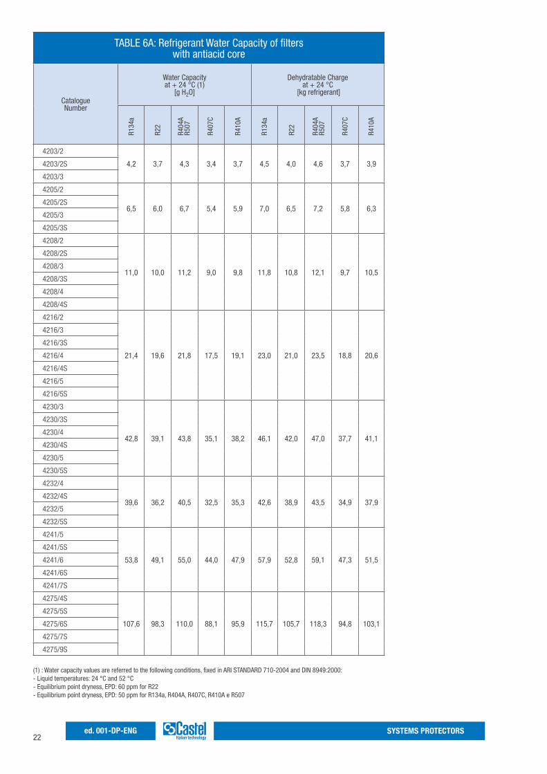
(1) : Water capacity values are referred to the following conditions, fixed in ARI STANDARD 710-2004 and DIN 8949:2000:- Liquid temperatures: 24 °C and 52 °C- Equilibrium point dryness, EPD: 60 ppm for R22- Equilibrium point dryness, EPD: 50 ppm for R134a, R404A, R407C, R410A e R507
TABLE 6A: Refrigerant Water Capacity of filters with antiacid core
CatalogueNumber
Water Capacityat + 24 °C (1)
[g H2O]
Dehydratable Chargeat + 24 °C
[kg refrigerant]
4203/2
4,2 3,7 4,3 3,4 3,7 4,5 4,0 4,6 3,7 3,94203/2S
4203/3
4205/2
6,5 6,0 6,7 5,4 5,9 7,0 6,5 7,2 5,8 6,34205/2S
4205/3
4205/3S
4208/2
11,0 10,0 11,2 9,0 9,8 11,8 10,8 12,1 9,7 10,5
4208/2S
4208/3
4208/3S
4208/4
4208/4S
4216/2
21,4 19,6 21,8 17,5 19,1 23,0 21,0 23,5 18,8 20,6
4216/3
4216/3S
4216/4
4216/4S
4216/5
4216/5S
4230/3
42,8 39,1 43,8 35,1 38,2 46,1 42,0 47,0 37,7 41,1
4230/3S
4230/4
4230/4S
4230/5
4230/5S
4232/4
39,6 36,2 40,5 32,5 35,3 42,6 38,9 43,5 34,9 37,94232/4S
4232/5
4232/5S
4241/5
53,8 49,1 55,0 44,0 47,9 57,9 52,8 59,1 47,3 51,5
4241/5S
4241/6
4241/6S
4241/7S
4275/4S
107,6 98,3 110,0 88,1 95,9 115,7 105,7 118,3 94,8 103,1
4275/5S
4275/6S
4275/7S
4275/9S
R407
C
R410
A
R134
a
R22
R404
AR5
07
R407
C
R410
A
R134
a
R22
R404
AR5
07
23SYSTEMS PROTECTORS ed. 001-DP-ENG
(1) : Water capacity values are referred to the following conditions, fixed in ARI STANDARD 710-2004 and DIN 8949:2000:- Liquid temperatures: 24 °C and 52 °C- Equilibrium point dryness, EPD: 60 ppm for R22- Equilibrium point dryness, EPD: 50 ppm for R134a, R404A, R407C, R410A e R507
R410
A
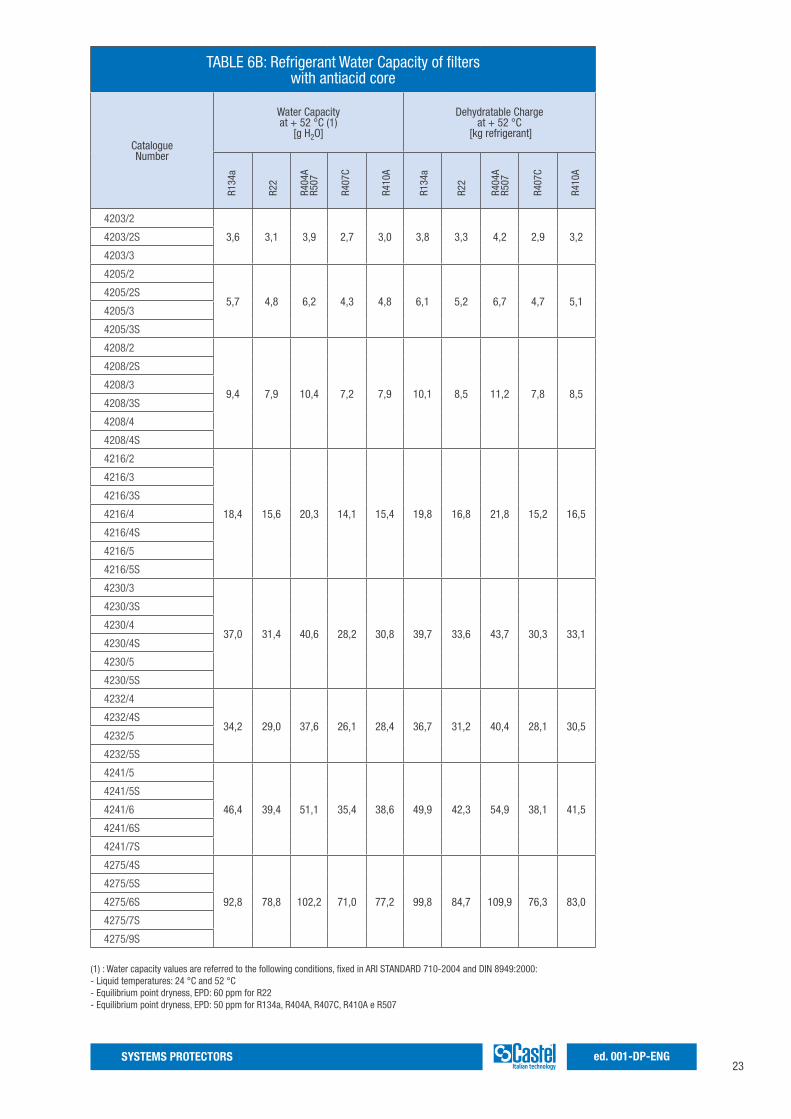
TABLE 6B: Refrigerant Water Capacity of filters with antiacid core
CatalogueNumber
Water Capacityat + 52 °C (1)
[g H2O]
Dehydratable Chargeat + 52 °C
[kg refrigerant]
4203/2
3,6 3,1 3,9 2,7 3,0 3,8 3,3 4,2 2,9 3,24203/2S
4203/3
4205/2
5,7 4,8 6,2 4,3 4,8 6,1 5,2 6,7 4,7 5,14205/2S
4205/3
4205/3S
4208/2
9,4 7,9 10,4 7,2 7,9 10,1 8,5 11,2 7,8 8,5
4208/2S
4208/3
4208/3S
4208/4
4208/4S
4216/2
18,4 15,6 20,3 14,1 15,4 19,8 16,8 21,8 15,2 16,5
4216/3
4216/3S
4216/4
4216/4S
4216/5
4216/5S
4230/3
37,0 31,4 40,6 28,2 30,8 39,7 33,6 43,7 30,3 33,1
4230/3S
4230/4
4230/4S
4230/5
4230/5S
4232/4
34,2 29,0 37,6 26,1 28,4 36,7 31,2 40,4 28,1 30,54232/4S
4232/5
4232/5S
4241/5
46,4 39,4 51,1 35,4 38,6 49,9 42,3 54,9 38,1 41,5
4241/5S
4241/6
4241/6S
4241/7S
4275/4S
92,8 78,8 102,2 71,0 77,2 99,8 84,7 109,9 76,3 83,0
4275/5S
4275/6S
4275/7S
4275/9S
R407
C
R410
A
R134
a
R22
R404
AR5
07
R410
A
R134
a
R22
R404
AR5
07
R407
C
24SYSTEMS PROTECTORSed. 001-DP-ENG
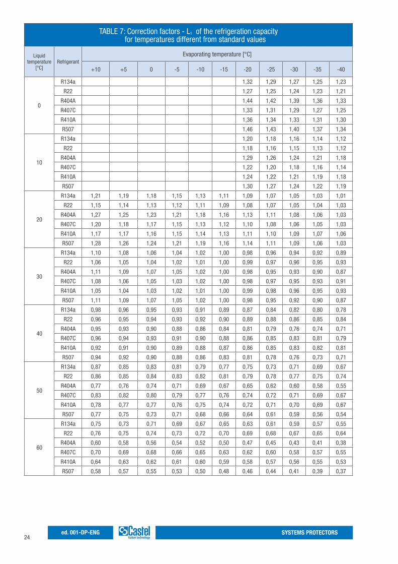
TABLE 7: Correction factors - L1 of the refrigeration capacity for temperatures different from standard values
Liquidtemperature
[°C]Refrigerant
Evaporating temperature [°C]
+10 +5 0 -5 -10 -15 -20 -25 -30 -35 -40
0
R134a 1,32 1,29 1,27 1,25 1,23
R22 1,27 1,25 1,24 1,23 1,21
R404A 1,44 1,42 1,39 1,36 1,33
R407C 1,33 1,31 1,29 1,27 1,25
R410A 1,36 1,34 1,33 1,31 1,30
R507 1,46 1,43 1,40 1,37 1,34
10
R134a 1,20 1,18 1,16 1,14 1,12
R22 1,18 1,16 1,15 1,13 1,12
R404A 1,29 1,26 1,24 1,21 1,18
R407C 1,22 1,20 1,18 1,16 1,14
R410A 1,24 1,22 1,21 1,19 1,18
R507 1,30 1,27 1,24 1,22 1,19
20
R134a 1,21 1,19 1,18 1,15 1,13 1,11 1,09 1,07 1,05 1,03 1,01
R22 1,15 1,14 1,13 1,12 1,11 1,09 1,08 1,07 1,05 1,04 1,03
R404A 1,27 1,25 1,23 1,21 1,18 1,16 1,13 1,11 1,08 1,06 1,03
R407C 1,20 1,18 1,17 1,15 1,13 1,12 1,10 1,08 1,06 1,05 1,03
R410A 1,17 1,17 1,16 1,15 1,14 1,13 1,11 1,10 1,09 1,07 1,06
R507 1,28 1,26 1,24 1,21 1,19 1,16 1,14 1,11 1,09 1,06 1,03
30
R134a 1,10 1,08 1,06 1,04 1,02 1,00 0,98 0,96 0,94 0,92 0,89
R22 1,06 1,05 1,04 1,02 1,01 1,00 0,99 0,97 0,96 0,95 0,93
R404A 1,11 1,09 1,07 1,05 1,02 1,00 0,98 0,95 0,93 0,90 0,87
R407C 1,08 1,06 1,05 1,03 1,02 1,00 0,98 0,97 0,95 0,93 0,91
R410A 1,05 1,04 1,03 1,02 1,01 1,00 0,99 0,98 0,96 0,95 0,93
R507 1,11 1,09 1,07 1,05 1,02 1,00 0,98 0,95 0,92 0,90 0,87
40
R134a 0,98 0,96 0,95 0,93 0,91 0,89 0,87 0,84 0,82 0,80 0,78
R22 0,96 0,95 0,94 0,93 0,92 0,90 0,89 0,88 0,86 0,85 0,84
R404A 0,95 0,93 0,90 0,88 0,86 0,84 0,81 0,79 0,76 0,74 0,71
R407C 0,96 0,94 0,93 0,91 0,90 0,88 0,86 0,85 0,83 0,81 0,79
R410A 0,92 0,91 0,90 0,89 0,88 0,87 0,86 0,85 0,83 0,82 0,81
R507 0,94 0,92 0,90 0,88 0,86 0,83 0,81 0,78 0,76 0,73 0,71
50
R134a 0,87 0,85 0,83 0,81 0,79 0,77 0,75 0,73 0,71 0,69 0,67
R22 0,86 0,85 0,84 0,83 0,82 0,81 0,79 0,78 0,77 0,75 0,74
R404A 0,77 0,76 0,74 0,71 0,69 0,67 0,65 0,62 0,60 0,58 0,55
R407C 0,83 0,82 0,80 0,79 0,77 0,76 0,74 0,72 0,71 0,69 0,67
R410A 0,78 0,77 0,77 0,76 0,75 0,74 0,72 0,71 0,70 0,69 0,67
R507 0,77 0,75 0,73 0,71 0,68 0,66 0,64 0,61 0,59 0,56 0,54
60
R134a 0,75 0,73 0,71 0,69 0,67 0,65 0,63 0,61 0,59 0,57 0,55
R22 0,76 0,75 0,74 0,73 0,72 0,70 0,69 0,68 0,67 0,65 0,64
R404A 0,60 0,58 0,56 0,54 0,52 0,50 0,47 0,45 0,43 0,41 0,38
R407C 0,70 0,69 0,68 0,66 0,65 0,63 0,62 0,60 0,58 0,57 0,55
R410A 0,64 0,63 0,62 0,61 0,60 0,59 0,58 0,57 0,56 0,55 0,53
R507 0,58 0,57 0,55 0,53 0,50 0,48 0,46 0,44 0,41 0,39 0,37
1
25SYSTEMS PROTECTORS ed. 001-DP-ENG
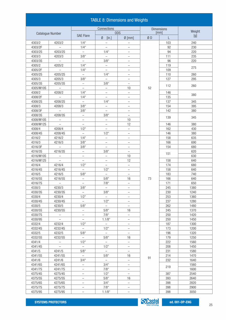
TABLE 8: Dimensions and Weights
Catalogue NumberConnections Dimensions
[mm] Weight [g]SAE Flare
ODSØ [in.] Ø [mm] Ø D L
4303/2 4203/2 1/4" – –
52
103 2404303/2F – 1/4" – – 92 2304303/2S 4203/2S – 1/4" – 94 2204303/3 4203/3 3/8" – – 111 2354303/3S – – 3/8" – 96 2204305/2 4205/2 1/4" – – 119
2754305/2F – 1/4" – – 1094305/2S 4205/2S – 1/4" – 110 2604305/3 4205/3 3/8" – – 127 2954305/3S 4205/3S – 3/8" –
112 2604305/M10S – – – 104308/2 4208/2 1/4" – – 146
3804308/2F – 1/4" – – 1354308/2S 4208/2S – 1/4" – 137 3454308/3 4208/3 3/8" – – 154 3954308/3F – 3/8" – – 142 3804308/3S 4208/3S – 3/8" –
139 3454308/M10S – – – 104308/M12S – – – 12 146 3804308/4 4208/4 1/2" – – 162 4304308/4S 4208/4S – 1/2" – 146 3804316/2 4216/2 1/4" – –
73
158 6354316/3 4216/3 3/8" – – 166 6904316/3F – 3/8" – – 154 6804316/3S 4216/3S – 3/8" –
151620
4316/M10S – – – 10 6304316/M12S – – – 12 158 6404316/4 4216/4 1/2" – – 174 6804316/4S 4216/4S – 1/2" – 158 6404316/5 4216/5 5/8" – – 183 7404316/5S 4216/5S – 5/8" 16 166 6404316/7S – – 7/8" – 171 6504330/3 4230/3 3/8" – – 245 13804330/3S 4230/3S – 3/8" – 230 12404330/4 4230/4 1/2" – – 253 13604330/4S 4230/4S – 1/2" – 237 12804330/5 4230/5 5/8" – – 262 14804330/5S 4230/5S – 5/8" 16 245 13704330/7S – – 7/8" – 250 14204330/9S – – 1.1/8" – 250 14504332/4 4232/4 1/2" – –
91
187 13004332/4S 4232/4S – 1/2" – 173 12004332/5 4232/5 5/8" – – 196 13204332/5S 4232/5S – 5/8" 16 179 12504341/4 – 1/2" – – 222 15604341/4S – – 1/2" – 208 14504341/5 4241/5 5/8" – – 231 15804341/5S 4241/5S – 5/8" 16 214 14704341/6 4241/6 3/4" – – 232 16404341/6S 4241/6S – 3/4" –
2191560
4341/7S 4241/7S – 7/8" – 16004375/4S 4275/4S – 1/2" – 387 25404375/5S 4275/5S – 5/8" 16 393 26404375/6S 4275/6S – 3/4" – 398 28204375/7S 4275/7S – 7/8" – 398 29004375/9S 4275/9S – 1.1/8" – 398 3050
26SYSTEMS PROTECTORSed. 001-DP-ENG
27SYSTEMS PROTECTORS ed. 001-DP-ENG
SOLID CORE FILTER DRIERS WITH SIGHT GLASS SERIES 41
Approved by Underwriters Laboratories Inc.
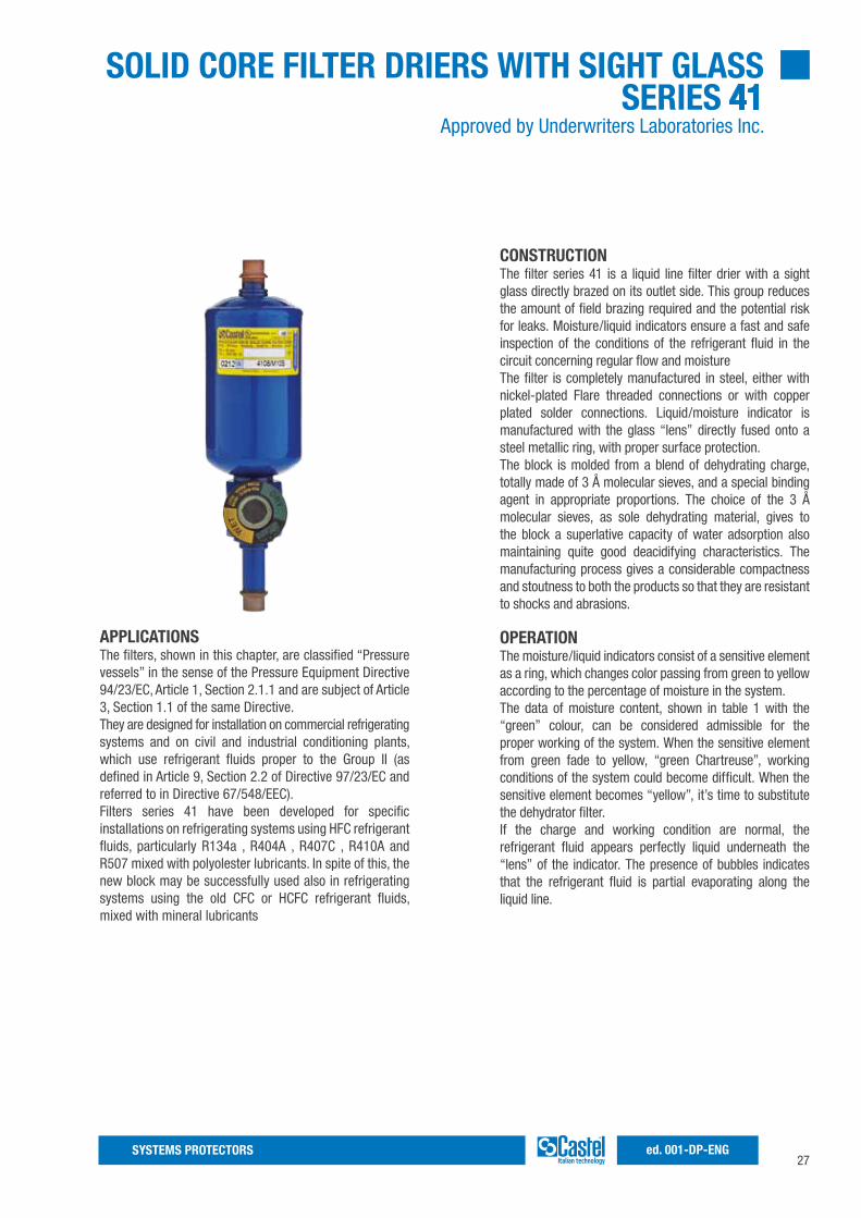
CONSTRUCTIONThe filter series 41 is a liquid line filter drier with a sight glass directly brazed on its outlet side. This group reduces the amount of field brazing required and the potential risk for leaks. Moisture/liquid indicators ensure a fast and safe inspection of the conditions of the refrigerant fluid in the circuit concerning regular flow and moistureThe filter is completely manufactured in steel, either with nickel-plated Flare threaded connections or with copper plated solder connections. Liquid/moisture indicator is manufactured with the glass “lens” directly fused onto a steel metallic ring, with proper surface protection.The block is molded from a blend of dehydrating charge, totally made of 3 Å molecular sieves, and a special binding agent in appropriate proportions. The choice of the 3 Å molecular sieves, as sole dehydrating material, gives to the block a superlative capacity of water adsorption also maintaining quite good deacidifying characteristics. The manufacturing process gives a considerable compactness and stoutness to both the products so that they are resistant to shocks and abrasions.
OPERATIONThe moisture/liquid indicators consist of a sensitive element as a ring, which changes color passing from green to yellow according to the percentage of moisture in the system.The data of moisture content, shown in table 1 with the “green” colour, can be considered admissible for the proper working of the system. When the sensitive element from green fade to yellow, “green Chartreuse”, working conditions of the system could become difficult. When the sensitive element becomes “yellow”, it’s time to substitute the dehydrator filter.If the charge and working condition are normal, the refrigerant fluid appears perfectly liquid underneath the “lens” of the indicator. The presence of bubbles indicates that the refrigerant fluid is partial evaporating along the liquid line.
APPLICATIONSThe filters, shown in this chapter, are classified “Pressure vessels” in the sense of the Pressure Equipment Directive 94/23/EC, Article 1, Section 2.1.1 and are subject of Article 3, Section 1.1 of the same Directive.They are designed for installation on commercial refrigerating systems and on civil and industrial conditioning plants, which use refrigerant fluids proper to the Group II (as defined in Article 9, Section 2.2 of Directive 97/23/EC and referred to in Directive 67/548/EEC).Filters series 41 have been developed for specific installations on refrigerating systems using HFC refrigerant fluids, particularly R134a , R404A , R407C , R410A and R507 mixed with polyolester lubricants. In spite of this, the new block may be successfully used also in refrigerating systems using the old CFC or HCFC refrigerant fluids, mixed with mineral lubricants
28SYSTEMS PROTECTORSed. 001-DP-ENG
equilibrium. However, the moisture indication is given normally when the plant is in function and the fluid is flowingThe brazing of filter/indicator with solder connections should be carried out with care, using a low melting point filler material. In any case, avoid direct contact between the torch flame and the indicator body or glass, which could be damaged and compromise the proper functioning of the indicator
INSTALLATIONAt the start-up the color of the sensitive element may be yellow, due to exposure to air humidity and to moisture in the circuit. When the moisture of the refrigerant is brought back to acceptable levels with the dehydrator, the indicator color is once again green. This is evidence that equilibrium has been re-established. In case of persisting yellow, measures have to be taken to eliminate moisture. Only when the sensitive element comes back to green, there is evidence that adopted measures were effective. About 12 hours of system operation are required to achieve
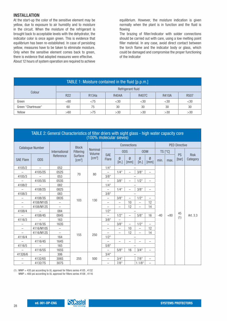
TABLE 1: Moisture contained in the fluid [p.p.m.]
ColourRefrigerant fluid
R22 R134a R404A R407C R410A R507
Green <60 <75 <30 <30 <30 <30
Green "Chartreuse" 60 75 30 30 30 30
Yellow >60 >75 >30 >30 >30 >30
TABLE 2: General Characteristics of filter driers with sight glass - high water capacity core (100% molecular sieves)
Catalogue NumberInternationalReference
Block FilteringSurface[cm2]
NominalVolume[cm3]
Connections PED Directive
SAE Flare
ODS ODM TS [°C]PS
[bar]Risk
CategorySAE Flare ODS Ø [in.]
Ø [mm]
Ø [in.]
Ø [mm] min. max.
4105/2 – 052
70 80
1/4" –
-40 +8045(1)
Art. 3.3
– 4105/2S 052S – 1/4" – 3/8" –4105/3 – 053 3/8" –
– 4105/3S 053S – 3/8" – 1/2" –4108/2 – 082
103 130
1/4" –– 4108/2S 082S – 1/4" – 3/8" –
4108/3 – 083 3/8" –– 4108/3S 083S – 3/8" – 1/2" –– 4108/M10S – – – 10 – 12– 4108/M12S – – – 12 – 14
4108/4 – 084 1/2" –– 4108/4S 084S – 1/2" – 5/8" 16
4116/3 – 163
155 250
3/8" –– 4116/3S 163S – 3/8" – 1/2" –– 4116/M10S – – – 10 – 12– 4116/M12S – – – 12 – 14
4116/4 – 164 1/2" –– 4116/4S 164S – – – – –
4116/5 – 165 5/8" –– 4116/5S 165S – 5/8" 16 3/4" –
41326/6 – 306255 500
3/4" –– 4132/6S 306S – 3/4" 7/8" –– 4132/7S 307S – 7/8" 1.1/8" –
(1) : MWP = 435 psi according to UL approval for filters series 4105 , 4132 MWP = 400 psi according to UL approval for filters series 4108 , 4116
29SYSTEMS PROTECTORS ed. 001-DP-ENG
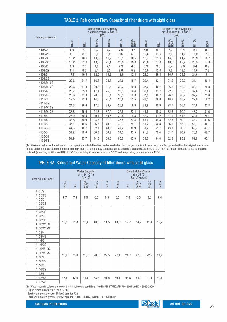
TABLE 3: Refrigerant Flow Capacity of filter driers with sight glass
Catalogue Number
Refrigerant Flow Capacity,pressure drop 0,07 bar (1)
[kW]
Refrigerant Flow Capacity,pressure drop 0,14 bar (1)
[kW]
4105/2 6,6 7,2 4,7 7,2 7,0 4,6 8,6 9,4 6,2 9,4 9,1 5,94105/2S 8,1 8,9 5,9 8,9 8,6 5,6 10,6 11,6 7,6 11,6 11,2 7,34105/3 15,2 16,6 10,9 16,7 16,1 10,5 19,7 21,6 14,2 21,7 20,9 13,74105/3S 19,2 21,0 13,8 21,1 20,3 13,3 25,0 27,3 18,0 27,4 26,5 17,34108/2 6,9 7,5 4,9 7,5 7,3 4,8 8,9 9,8 6,4 9,8 9,4 6,24108/2S 8,4 9,2 6,1 9,2 8,9 5,8 10,9 12,0 7,9 12,0 11,6 7,64108/3 17,8 19,5 12,9 19,6 18,9 12,4 23,2 25,4 16,7 25,5 24,6 16,14108/3S
22,6 24,7 16,3 24,8 23,9 15,7 29,4 32,1 21,2 32,2 31,1 20,44108/M10S4108/M12S 28,6 31,3 20,6 31,4 30,3 19,8 37,2 40,7 26,8 40,9 39,4 25,84108/4 23,7 25,9 17,1 26,0 25,1 16,4 30,8 33,7 22,2 33,8 32,6 21,34108/4S 28,6 31,3 20,6 31,4 30,3 19,8 37,2 40,7 26,8 40,9 39,4 25,84116/3 19,5 21,3 14,0 21,4 20,6 13,5 26,3 28,8 18,9 28,9 27,9 18,24116/3S
24,3 26,6 17,5 26,7 25,8 16,9 32,9 35,9 23,7 36,1 34,8 22,84116/M10S4116/M12S 33,8 36,9 24,3 37,0 35,8 23,4 45,6 49,8 32,8 50,0 48,3 31,64116/4 27,9 30,5 20,1 30,6 29,6 19,3 37,7 41,2 27,1 41,3 39,9 26,14116/4S 33,8 36,9 24,3 37,0 35,8 23,4 45,6 49,8 32,8 50,0 48,3 31,64116/5 37,1 40,6 26,8 40,8 39,3 25,7 50,2 54,8 36,1 55,0 53,1 34,74116/5S 44,6 48,7 32,1 48,9 47,2 30,9 60,2 65,7 43,3 66,0 63,7 41,74132/6 51,2 56,0 36,9 56,2 54,3 35,5 71,7 78,4 51,7 78,7 76,0 49,74132/6S
61,9 67,7 44,6 68,0 65,6 42,9 86,7 94,8 62,5 95,2 91,8 60,14132/7S
R134
a
R22
R404
A
R407
C
R410
A
R134
a
R22
R404
AR5
07
R407
C
R410
A
R507
R404
AR5
07
(1) : Maximum values of the refrigerant flow capacity at which the drier can be used when fluid dehydration is not the a major problem, provided that the original moisture is limited before the installation of the drier. The maximum refrigerant flow capacities are referred to a total pressure drop of 0,07 bar / 0,14 bar , inlet and outlet connections included, (according to ARI STANDARD 710-2004 - with liquid temperature at + 30 °C and evaporating temperature at - 15 °C )
TABLE 4A: Refrigerant Water Capacity of filter driers with sight glass
Catalogue Number
Water Capacityat + 24 °C (1)
[g H2O]
Dehydratable Chargeat + 24 °C
[kg refrigerant]
4105/2
7,7 7,1 7,9 6,3 6,9 8,3 7,6 8,5 6,8 7,44105/2S4105/34105/3S4108/2
12,9 11,8 13,2 10,6 11,5 13,9 12,7 14,2 11,4 12,4
4108/2S4108/34108/3S4108/M10S4108/M12S4108/44108/4S4116/3
25,2 23,0 25,7 20,6 22,5 27,1 24,7 27,6 22,2 24,2
4116/3S4116/M10S4116/M12S4116/44116/4S4116/54116/5S4132/6
46,6 42,6 47,6 38,2 41,5 50,1 45,8 51,2 41,1 44,64132/6S4132/7S
R134
a
R22
R407
C
R410
A
R134
a
R22
R404
AR5
07
R407
C
R410
A
R404
AR5
07
(1) : Water capacity values are referred to the following conditions, fixed in ARI STANDARD 710-2004 and DIN 8949:2000:- Liquid temperatures: 24 °C and 52 °C- Equilibrium point dryness, EPD: 60 ppm for R22- Equilibrium point dryness, EPD: 50 ppm for R134a , R404A , R407C , R410A e R507
30SYSTEMS PROTECTORSed. 001-DP-ENG
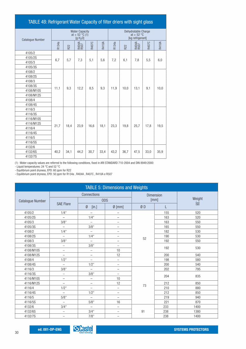
TABLE 5: Dimensions and Weights
Catalogue Number
Connections Dimension[mm] Weight
[g]SAE FlareODS
Ø [in.] Ø [mm] Ø D L
4105/2 1/4" – –
52
155 5204105/2S – 1/4" – 163 5204105/3 3/8" – – 163 5504105/3S – 3/8" – 165 5504108/2 1/4" – – 182 5304108/2S – 1/4" – 190 5304108/3 3/8" – – 192 5504108/3S – 3/8" –
192 5304108/M10S – – 104108/M12S – – 12 200 5404108/4 1/2" – – 198 5804108/4S – 1/2" – 200 5404116/3 3/8" – –
73
202 7954116/3S – 3/8" –
204 8354116/M10S – – 104116/M12S – – 12 212 8504116/4 1/2" – – 210 8804116/4S – 1/2" – 212 8504116/5 5/8" – – 219 9404116/5S – 5/8" 16 221 8704132/6 3/4" – –
91233 1400
4132/6S – 3/4" – 238 13804132/7S – 7/8" – 238 1400
(1) : Water capacity values are referred to the following conditions, fixed in ARI STANDARD 710-2004 and DIN 8949:2000:- Liquid temperatures: 24 °C and 52 °C- Equilibrium point dryness, EPD: 60 ppm for R22- Equilibrium point dryness, EPD: 50 ppm for R134a , R404A , R407C , R410A e R507
TABLE 4B: Refrigerant Water Capacity of filter driers with sight glass
Catalogue Number
Water Capacityat + 52 °C (1)
[g H2O]
Dehydratable Chargeat + 52 °C
[kg refrigerant]
4105/2
6,7 5,7 7,3 5,1 5,6 7,2 6,1 7,8 5,5 6,04105/2S4105/34105/3S4108/2
11,1 9,3 12,2 8,5 9,3 11,9 10,0 13,1 9,1 10,0
4108/2S4108/34108/3S4108/M10S4108/M12S4108/44108/4S4116/3
21,7 18,4 23,9 16,6 18,1 23,3 19,8 25,7 17,8 19,5
4116/3S4116/M10S4116/M12S4116/44116/4S4116/54116/5S4132/6
40,2 34,1 44,2 30,7 33,4 43,2 36,7 47,5 33,0 35,94132/6S4132/7S
R134
a
R22
R407
C
R410
A
R134
a
R22
R404
AR5
07
R407
C
R410
A
R404
AR5
07
31SYSTEMS PROTECTORS ed. 001-DP-ENG
32SYSTEMS PROTECTORSed. 001-DP-ENG
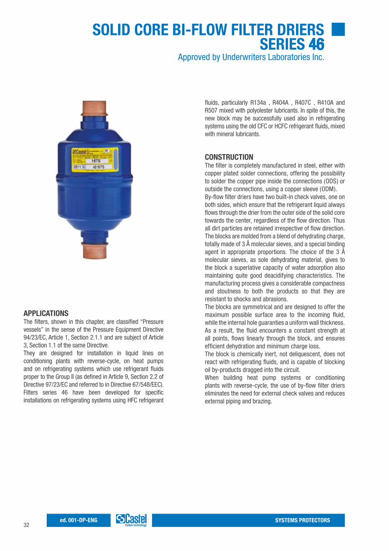
SOLID CORE BI-FLOW FILTER DRIERS SERIES 46
Approved by Underwriters Laboratories Inc.
APPLICATIONSThe filters, shown in this chapter, are classified “Pressure vessels” in the sense of the Pressure Equipment Directive 94/23/EC, Article 1, Section 2.1.1 and are subject of Article 3, Section 1.1 of the same Directive.They are designed for installation in liquid lines on conditioning plants with reverse-cycle, on heat pumps and on refrigerating systems which use refrigerant fluids proper to the Group II (as defined in Article 9, Section 2.2 of Directive 97/23/EC and referred to in Directive 67/548/EEC).Filters series 46 have been developed for specific installations on refrigerating systems using HFC refrigerant
fluids, particularly R134a , R404A , R407C , R410A and R507 mixed with polyolester lubricants. In spite of this, the new block may be successfully used also in refrigerating systems using the old CFC or HCFC refrigerant fluids, mixed with mineral lubricants.
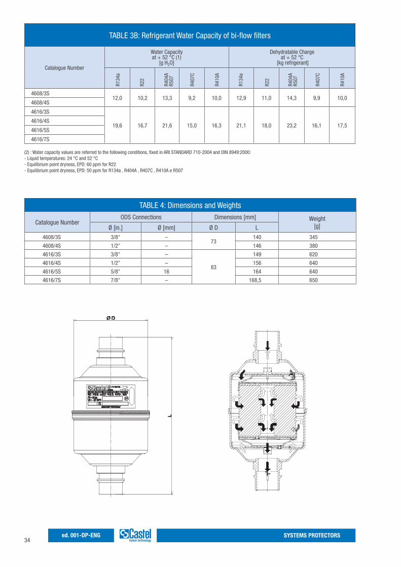
CONSTRUCTIONThe filter is completely manufactured in steel, either with copper plated solder connections, offering the possibility to solder the copper pipe inside the connections (ODS) or outside the connections, using a copper sleeve (ODM).By-flow filter driers have two built-in check valves, one on both sides, which ensure that the refrigerant liquid always flows through the drier from the outer side of the solid core towards the center, regardless of the flow direction. Thus all dirt particles are retained irrespective of flow direction.The blocks are molded from a blend of dehydrating charge, totally made of 3 Å molecular sieves, and a special binding agent in appropriate proportions. The choice of the 3 Å molecular sieves, as sole dehydrating material, gives to the block a superlative capacity of water adsorption also maintaining quite good deacidifying characteristics. The manufacturing process gives a considerable compactness and stoutness to both the products so that they are resistant to shocks and abrasions.The blocks are symmetrical and are designed to offer the maximum possible surface area to the incoming fluid, while the internal hole guaranties a uniform wall thickness. As a result, the fluid encounters a constant strength at all points, flows linearly through the block, and ensures efficient dehydration and minimum charge loss.The block is chemically inert, not deliquescent, does not react with refrigerating fluids, and is capable of blocking oil by-products dragged into the circuit.When building heat pump systems or conditioning plants with reverse-cycle, the use of by-flow filter driers eliminates the need for external check valves and reduces external piping and brazing.
33SYSTEMS PROTECTORS ed. 001-DP-ENG
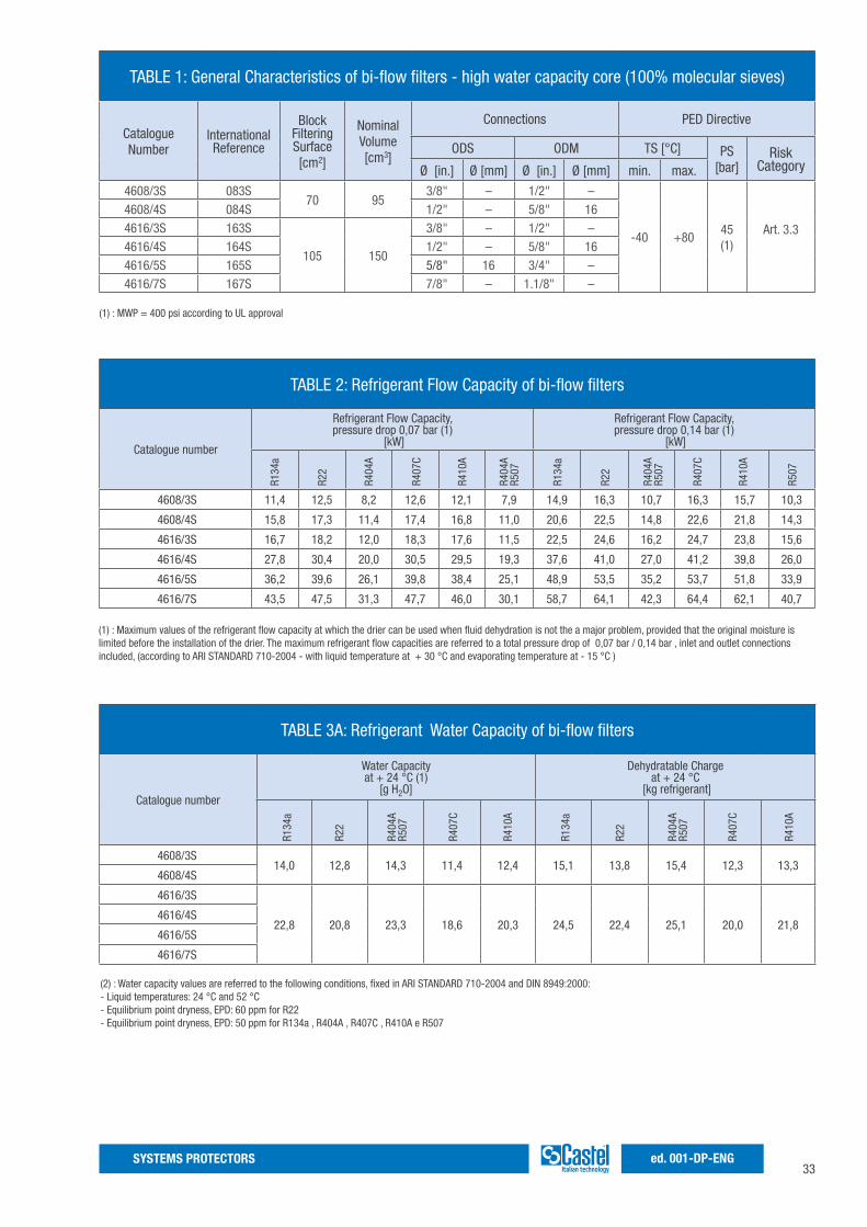
TABLE 1: General Characteristics of bi-flow filters - high water capacity core (100% molecular sieves)
Catalogue Number
InternationalReference
Block FilteringSurface[cm2]
NominalVolume[cm3]
Connections PED Directive
ODS ODM TS [°C] PS [bar]
RiskCategoryØ [in.] Ø [mm] Ø [in.] Ø [mm] min. max.
4608/3S 083S70 95
3/8" – 1/2" –
-40 +8045(1)
Art. 3.3
4608/4S 084S 1/2" – 5/8" 164616/3S 163S
105 150
3/8" – 1/2" –4616/4S 164S 1/2" – 5/8" 164616/5S 165S 5/8" 16 3/4" –4616/7S 167S 7/8" – 1.1/8" –
(1) : MWP = 400 psi according to UL approval
(1) : Maximum values of the refrigerant flow capacity at which the drier can be used when fluid dehydration is not the a major problem, provided that the original moisture is limited before the installation of the drier. The maximum refrigerant flow capacities are referred to a total pressure drop of 0,07 bar / 0,14 bar , inlet and outlet connections included, (according to ARI STANDARD 710-2004 - with liquid temperature at + 30 °C and evaporating temperature at - 15 °C )
TABLE 3A: Refrigerant Water Capacity of bi-flow filters
Catalogue number
Water Capacityat + 24 °C (1)
[g H2O]
Dehydratable Chargeat + 24 °C
[kg refrigerant]
4608/3S14,0 12,8 14,3 11,4 12,4 15,1 13,8 15,4 12,3 13,3
4608/4S
4616/3S
22,8 20,8 23,3 18,6 20,3 24,5 22,4 25,1 20,0 21,84616/4S
4616/5S
4616/7S
R134
a
R22
R407
C
R410
A
R134
a
R22
R404
AR5
07
R407
C
R410
A
R404
AR5
07
(2) : Water capacity values are referred to the following conditions, fixed in ARI STANDARD 710-2004 and DIN 8949:2000:- Liquid temperatures: 24 °C and 52 °C- Equilibrium point dryness, EPD: 60 ppm for R22- Equilibrium point dryness, EPD: 50 ppm for R134a , R404A , R407C , R410A e R507
TABLE 2: Refrigerant Flow Capacity of bi-flow filters
Catalogue number
Refrigerant Flow Capacity,pressure drop 0,07 bar (1)
[kW]
Refrigerant Flow Capacity,pressure drop 0,14 bar (1)
[kW]
4608/3S 11,4 12,5 8,2 12,6 12,1 7,9 14,9 16,3 10,7 16,3 15,7 10,3
4608/4S 15,8 17,3 11,4 17,4 16,8 11,0 20,6 22,5 14,8 22,6 21,8 14,3
4616/3S 16,7 18,2 12,0 18,3 17,6 11,5 22,5 24,6 16,2 24,7 23,8 15,6
4616/4S 27,8 30,4 20,0 30,5 29,5 19,3 37,6 41,0 27,0 41,2 39,8 26,0
4616/5S 36,2 39,6 26,1 39,8 38,4 25,1 48,9 53,5 35,2 53,7 51,8 33,9
4616/7S 43,5 47,5 31,3 47,7 46,0 30,1 58,7 64,1 42,3 64,4 62,1 40,7
R134
a
R22
R404
A
R407
C
R410
A
R134
a
R22
R404
AR5
07
R407
C
R410
A
R507
R404
AR5
07
34SYSTEMS PROTECTORSed. 001-DP-ENG
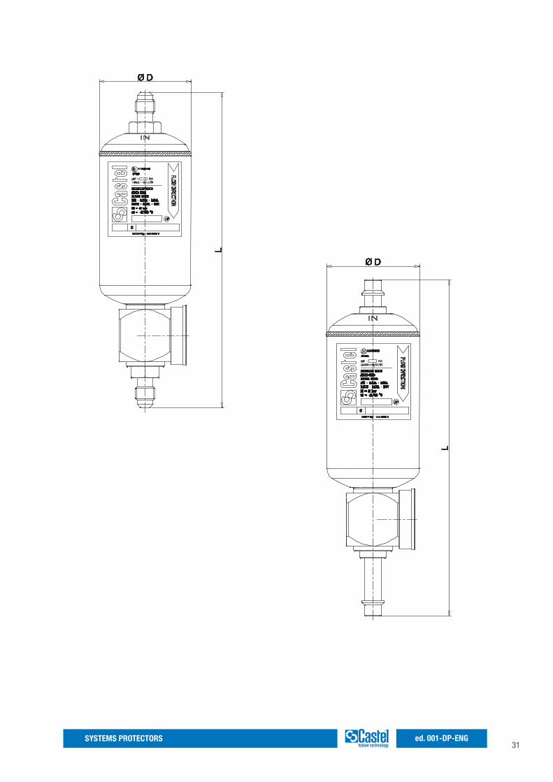
TABLE 4: Dimensions and Weights
Catalogue NumberODS Connections Dimensions [mm] Weight
[g]Ø [in.] Ø [mm] Ø D L
4608/3S 3/8" –73
140 345
4608/4S 1/2" – 146 380
4616/3S 3/8" –
83
149 620
4616/4S 1/2" – 156 640
4616/5S 5/8" 16 164 640
4616/7S 7/8" – 168,5 650
TABLE 3B: Refrigerant Water Capacity of bi-flow filters
Catalogue Number
Water Capacityat + 52 °C (1)
[g H2O]
Dehydratable Chargeat + 52 °C
[kg refrigerant]
4608/3S12,0 10,2 13,3 9,2 10,0 12,9 11,0 14,3 9,9 10,0
4608/4S
4616/3S
19,6 16,7 21,6 15,0 16,3 21,1 18,0 23,2 16,1 17,54616/4S
4616/5S
4616/7S
R134
a
R22
R407
C
R410
A
R134
a
R22
R404
AR5
07
R407
C
R410
A
R404
AR5
07
(2) : Water capacity values are referred to the following conditions, fixed in ARI STANDARD 710-2004 and DIN 8949:2000:- Liquid temperatures: 24 °C and 52 °C- Equilibrium point dryness, EPD: 60 ppm for R22- Equilibrium point dryness, EPD: 50 ppm for R134a , R404A , R407C , R410A e R507
35SYSTEMS PROTECTORS ed. 001-DP-ENG
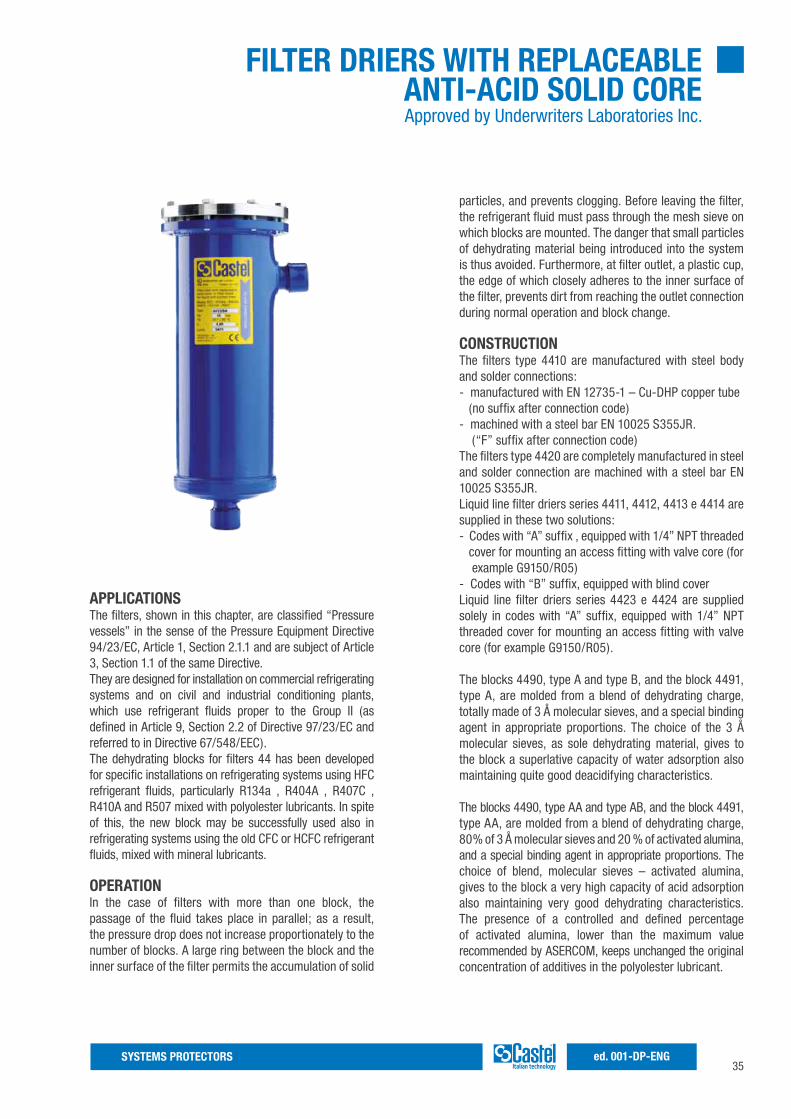
FILTER DRIERS WITH REPLACEABLE ANTI-ACID SOLID COREApproved by Underwriters Laboratories Inc.
APPLICATIONSThe filters, shown in this chapter, are classified “Pressure vessels” in the sense of the Pressure Equipment Directive 94/23/EC, Article 1, Section 2.1.1 and are subject of Article 3, Section 1.1 of the same Directive.They are designed for installation on commercial refrigerating systems and on civil and industrial conditioning plants, which use refrigerant fluids proper to the Group II (as defined in Article 9, Section 2.2 of Directive 97/23/EC and referred to in Directive 67/548/EEC).The dehydrating blocks for filters 44 has been developed for specific installations on refrigerating systems using HFC refrigerant fluids, particularly R134a , R404A , R407C , R410A and R507 mixed with polyolester lubricants. In spite of this, the new block may be successfully used also in refrigerating systems using the old CFC or HCFC refrigerant fluids, mixed with mineral lubricants.
OPERATIONIn the case of filters with more than one block, the passage of the fluid takes place in parallel; as a result, the pressure drop does not increase proportionately to the number of blocks. A large ring between the block and the inner surface of the filter permits the accumulation of solid
particles, and prevents clogging. Before leaving the filter, the refrigerant fluid must pass through the mesh sieve on which blocks are mounted. The danger that small particles of dehydrating material being introduced into the system is thus avoided. Furthermore, at filter outlet, a plastic cup, the edge of which closely adheres to the inner surface of the filter, prevents dirt from reaching the outlet connection during normal operation and block change.
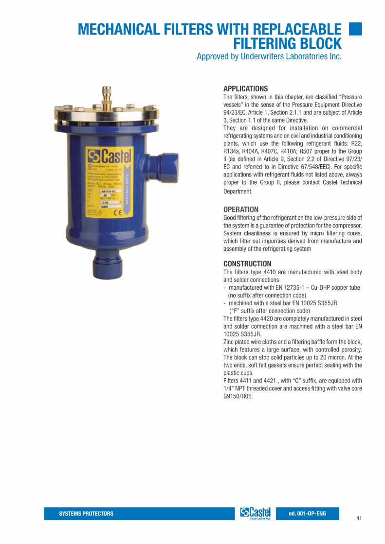
CONSTRUCTIONThe filters type 4410 are manufactured with steel body and solder connections:- manufactured with EN 12735-1 – Cu-DHP copper tube (no suffix after connection code)- machined with a steel bar EN 10025 S355JR. (“F” suffix after connection code)The filters type 4420 are completely manufactured in steel and solder connection are machined with a steel bar EN 10025 S355JR.Liquid line filter driers series 4411, 4412, 4413 e 4414 are supplied in these two solutions:- Codes with “A” suffix , equipped with 1/4” NPT threaded cover for mounting an access fitting with valve core (for example G9150/R05)- Codes with “B” suffix, equipped with blind coverLiquid line filter driers series 4423 e 4424 are supplied solely in codes with “A” suffix, equipped with 1/4” NPT threaded cover for mounting an access fitting with valve core (for example G9150/R05).
The blocks 4490, type A and type B, and the block 4491, type A, are molded from a blend of dehydrating charge, totally made of 3 Å molecular sieves, and a special binding agent in appropriate proportions. The choice of the 3 Å molecular sieves, as sole dehydrating material, gives to the block a superlative capacity of water adsorption also maintaining quite good deacidifying characteristics.
The blocks 4490, type AA and type AB, and the block 4491, type AA, are molded from a blend of dehydrating charge, 80% of 3 Å molecular sieves and 20 % of activated alumina, and a special binding agent in appropriate proportions. The choice of blend, molecular sieves – activated alumina, gives to the block a very high capacity of acid adsorption also maintaining very good dehydrating characteristics. The presence of a controlled and defined percentage of activated alumina, lower than the maximum value recommended by ASERCOM, keeps unchanged the original concentration of additives in the polyolester lubricant.
36SYSTEMS PROTECTORSed. 001-DP-ENG
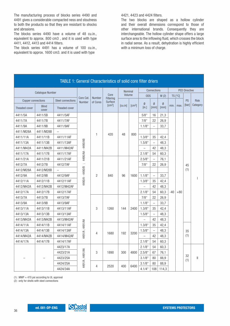
The manufacturing process of blocks series 4490 and 4491 gives a considerable compacted ness and stoutness to both the products so that they are resistant to shocks and abrasions.The blocks series 4490 have a volume of 48 cu.in., equivalent to approx. 800 cm3 , and it is used with type 4411, 4412, 4413 and 4414 filters.The block series 4491 has a volume of 100 cu.in., equivalent to approx. 1600 cm3. and it is used with type
4421, 4423 and 4424 filters.The two blocks are shaped as a hollow cylinder and their overall dimensions correspond to those of other international brands. Consequently they are interchangeable. The hollow cylinder shape offers a large surface area to the inflowing fluid, which crosses the block in radial sense. As a result, dehydration is highly efficient with a minimum loss of charge.
TABLE 1: General Characteristics of solid core filter driers
Catalogue Number
Core Cat. Number
Number of Cores
Core Filtering Surface[cm2]
Nominal Volume
Connections PED Directive
ODS W (2) TS [°C]
PS [bar]
Risk Category
Copper connections Steel connections
[cu.in] [cm3] Ø [in.]
Ø [mm]
Ø [mm] min. max.
Theaded cover Blindcover Theaded cover
4411/5A 4411/5B 4411/5AF
1 420 48 800
5/8" 16 21,3
-40 +80
45(1)
I
4411/7A 4411/7B 4411/7AF 7/8" 22 26,9
4411/9A 4411/9B 4411/9AF 1.1/8" – 33,7
4411/M28A 4411/M28B –
4411/11A 4411/11B 4411/11AF 1.3/8" 35 42,4
4411/13A 4411/13B 4411/13AF 1.5/8" – 48,3
4411/M42A 4411/M42B 4411/M42AF – 42 48,3
4411/17A 4411/17B 4411/17AF 2.1/8" 54 60,3
4411/21A 4411/21B 4411/21AF
2 840 96 1600
2.5/8" – 76,1
4412/7A 4412/7B 4412/7AF 7/8" 22 26,9
4412/M28A 4412/M28B –
4412/9A 4412/9B 4412/9AF 1.1/8" – 33,7
4412/11A 4412/11B 4412/11AF 1.3/8" 35 42,4
4412/M42A 4412/M42B 4412/M42AF – 42 48,3
4412/17A 4412/17B 4412/17AF 2.1/8" 54 60,3
4413/7A 4413/7B 4413/7AF
3 1260 144 2400
7/8" 22 26,9
4413/9A 4413/9B 4413/9AF 1.1/8" – 33,7
4413/11A 4413/11B 4413/11AF 1.3/8" 35 42,4
4413/13A 4413/13B 4413/13AF 1.5/8" – 48,3
4413/M42A 4413/M42B 4413/M42AF – 42 48,3
4414/11A 4414/11B 4414/11AF
4 1680 192 3200
1.3/8" 35 42,4
35(1)
4414/13A 4414/13B 4414/13AF 1.5/8" – 48,3
4414/M42A 4414/M42B 4414/M42AF – 42 48,3
4414/17A 4414/17B 4414/17AF 2.1/8" 54 60,3
– –
4423/17A
3 1890 300 4800
2.1/8" 54 60,3
32(1)
II
4423/21A 2.5/8" 67 76,1
4423/25A 3.1/8" 80 88,9
4424/25A4 2520 400 6400
3.1/8" 80 88,9
4424/34A 4.1/4" 108 114,3
(1) : MWP = 470 psi according to UL approval (2) : only for shells with steel connections
4490
/A -
449
0/B
;
4490
/AA
- 44
90/A
B44
91/A
; 44
91/A
A44
91/A
; 44
91/A
A
37SYSTEMS PROTECTORS ed. 001-DP-ENG
BLOCKS REPLACEMENTBlocks must be ordered separately from the filter. They are supplied in individual packages, which are hermetically sealed in suitable wrappings (type 4490), and in special bags (type 4491) for safe storage over long periods of time.Every cartridge is equipped of two seals in synthetic material to use like seal between the two cartridges and between the cartridge and its covers.If the filter is installed in a system without any by-pass, the block replacement has to be done following these instructions:1. Close the valve on the departing line2. Start the compressor and its auxiliaries in order to transfer the refrigerant charge into the high pressure side of the plant (liquid receiver);3. Stop the compressor at a suction pressure sufficiently higher than the atmospheric pressure;4. Shut off the service valve at the suction side of the compressor.NOTE: if during the transfer of the refrigerant to the high-
pressure side of the plant, the discharge pressures reach too high values (the condenser is flooded due to insufficient capacity of the liquid receiver), shut off the valve on the compressor suction side and stop immediately the compressor.5. Replace quickly the filter block. During the preparation of the new block, close the filter with a clean cloth. The slight over-pressure inside the filter and the ability of the technician will prevent air from getting into the plant.6. The internal cleanliness of the body is guaranteed by the cleaning effect of the cup, which is characteristic of Castel filters.If air is supposed to have entered the plant during filter block replacement, produce a vacuum in the low-pressure side of the plant, and always in the sector of the circuit involved.7. Open the valve on the departure of liquid line8. Slowly open the suction valve of the compressor and start the compressor and its auxiliaries.9. Top the charge up, if necessary.
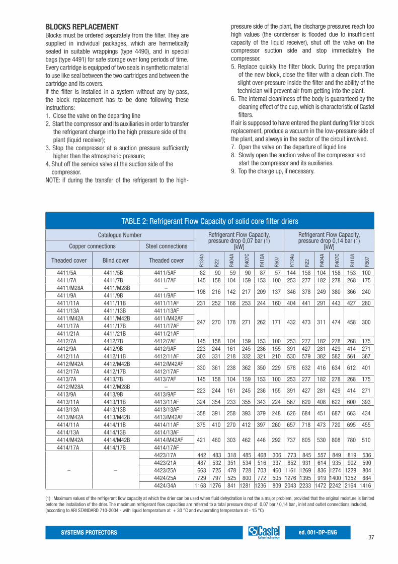
TABLE 2: Refrigerant Flow Capacity of solid core filter driers
Catalogue Number Refrigerant Flow Capacity,pressure drop 0,07 bar (1)
[kW]
Refrigerant Flow Capacity,pressure drop 0,14 bar (1)
[kW]Copper connections Steel connections
Theaded cover Blind cover Theaded cover
4411/5A 4411/5B 4411/5AF 82 90 59 90 87 57 144 158 104 158 153 1004411/7A 4411/7B 4411/7AF 145 158 104 159 153 100 253 277 182 278 268 1754411/M28A 4411/M28B –
198 216 142 217 209 137 346 378 249 380 366 2404411/9A 4411/9B 4411/9AF4411/11A 4411/11B 4411/11AF 231 252 166 253 244 160 404 441 291 443 427 2804411/13A 4411/13B 4411/13AF
247 270 178 271 262 171 432 473 311 474 458 3004411/M42A 4411/M42B 4411/M42AF4411/17A 4411/17B 4411/17AF4411/21A 4411/21B 4411/21AF4412/7A 4412/7B 4412/7AF 145 158 104 159 153 100 253 277 182 278 268 1754412/9A 4412/9B 4412/9AF 223 244 161 245 236 155 391 427 281 429 414 2714412/11A 4412/11B 4412/11AF 303 331 218 332 321 210 530 579 382 582 561 3674412/M42A 4412/M42B 4412/M42AF
330 361 238 362 350 229 578 632 416 634 612 4014412/17A 4412/17B 4412/17AF4413/7A 4413/7B 4413/7AF 145 158 104 159 153 100 253 277 182 278 268 1754412/M28A 4412/M28B –
223 244 161 245 236 155 391 427 281 429 414 2714413/9A 4413/9B 4413/9AF4413/11A 4413/11B 4413/11AF 324 354 233 355 343 224 567 620 408 622 600 3934413/13A 4413/13B 4413/13AF
358 391 258 393 379 248 626 684 451 687 663 4344413/M42A 4413/M42B 4413/M42AF4414/11A 4414/11B 4414/11AF 375 410 270 412 397 260 657 718 473 720 695 4554414/13A 4414/13B 4414/13AF
421 460 303 462 446 292 737 805 530 808 780 5104414/M42A 4414/M42B 4414/M42AF4414/17A 4414/17B 4414/17AF
– –
4423/17A 442 483 318 485 468 306 773 845 557 849 819 5364423/21A 487 532 351 534 516 337 852 931 614 935 902 5904423/25A 663 725 478 728 703 460 1161 1269 836 1274 1229 8044424/25A 729 797 525 800 772 505 1276 1395 919 1400 1352 8844424/34A 1168 1276 841 1281 1236 809 2043 2233 1472 2242 2164 1416
(1) : Maximum values of the refrigerant flow capacity at which the drier can be used when fluid dehydration is not the a major problem, provided that the original moisture is limited before the installation of the drier. The maximum refrigerant flow capacities are referred to a total pressure drop of 0,07 bar / 0,14 bar , inlet and outlet connections included, (according to ARI STANDARD 710-2004 - with liquid temperature at + 30 °C and evaporating temperature at - 15 °C)
R134
a
R22
R404
A
R407
C
R410
A
R507
R134
a
R22
R404
A
R407
C
R410
A
R507
38SYSTEMS PROTECTORSed. 001-DP-ENG
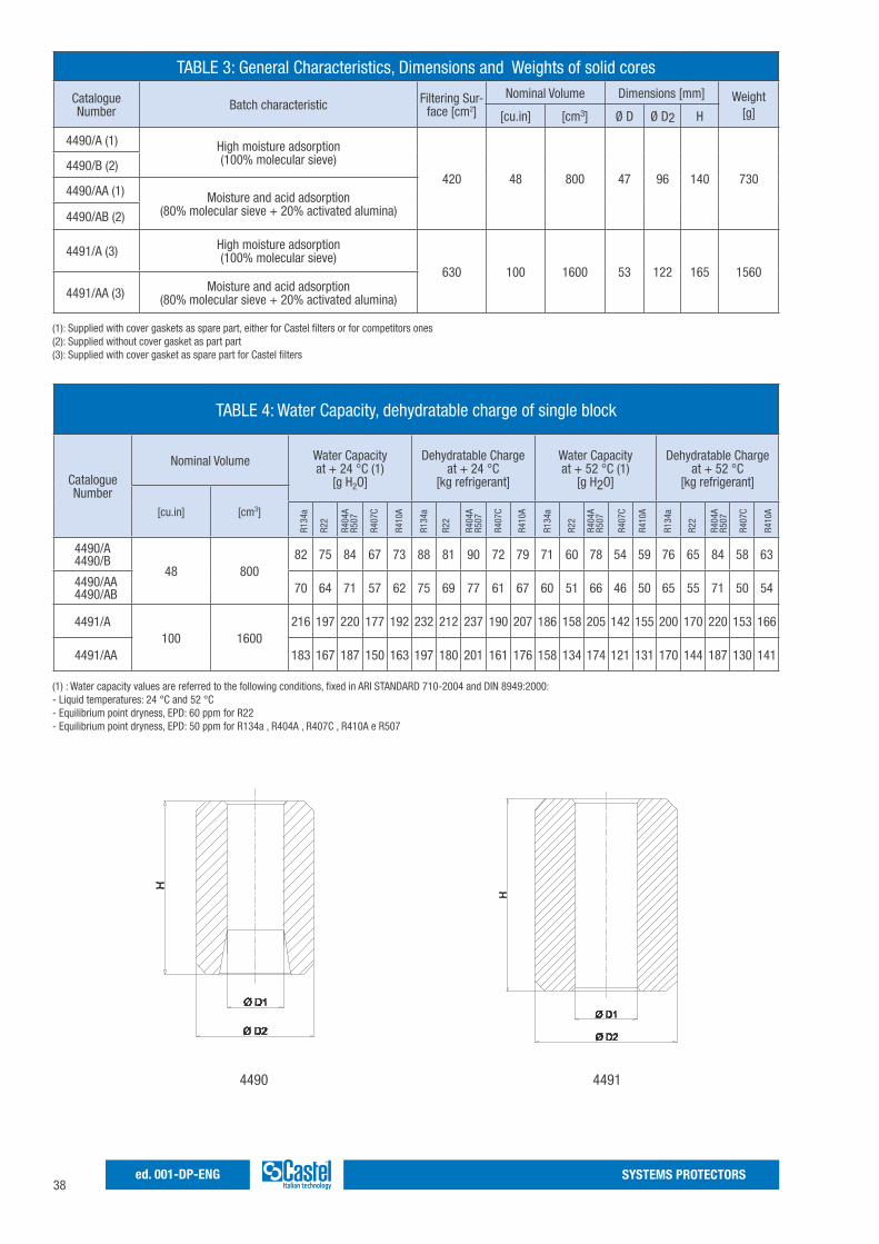
TABLE 4: Water Capacity, dehydratable charge of single block
Catalogue Number
Nominal Volume Water Capacityat + 24 °C (1)
[g H2O]
Dehydratable Chargeat + 24 °C
[kg refrigerant]
Water Capacityat + 52 °C (1)
[g H2O]
Dehydratable Chargeat + 52 °C
[kg refrigerant]
[cu.in] [cm3]
4490/A4490/B
48 80082 75 84 67 73 88 81 90 72 79 71 60 78 54 59 76 65 84 58 63
4490/AA4490/AB 70 64 71 57 62 75 69 77 61 67 60 51 66 46 50 65 55 71 50 54
4491/A100 1600
216 197 220 177 192 232 212 237 190 207 186 158 205 142 155 200 170 220 153 166
4491/AA 183 167 187 150 163 197 180 201 161 176 158 134 174 121 131 170 144 187 130 141
R134
a
R22
R407
C
R410
A
R134
a
R22
R404
AR5
07
R407
C
R410
A
R134
a
R22
R404
AR5
07
R407
C
R410
A
R134
a
R22
R404
AR5
07
R407
C
R410
A
R404
AR5
07
TABLE 3: General Characteristics, Dimensions and Weights of solid cores
Catalogue Number Batch characteristic Filtering Sur-
face [cm2]Nominal Volume Dimensions [mm] Weight
[g][cu.in] [cm3] Ø D Ø D2 H
4490/A (1) High moisture adsorption(100% molecular sieve)
420 48 800 47 96 140 7304490/B (2)
4490/AA (1) Moisture and acid adsorption(80% molecular sieve + 20% activated alumina)4490/AB (2)
4491/A (3) High moisture adsorption(100% molecular sieve)
630 100 1600 53 122 165 1560
4491/AA (3) Moisture and acid adsorption(80% molecular sieve + 20% activated alumina)
(1): Supplied with cover gaskets as spare part, either for Castel filters or for competitors ones (2): Supplied without cover gasket as part part (3): Supplied with cover gasket as spare part for Castel filters
(1) : Water capacity values are referred to the following conditions, fixed in ARI STANDARD 710-2004 and DIN 8949:2000:- Liquid temperatures: 24 °C and 52 °C- Equilibrium point dryness, EPD: 60 ppm for R22- Equilibrium point dryness, EPD: 50 ppm for R134a , R404A , R407C , R410A e R507
4490 4491
39SYSTEMS PROTECTORS ed. 001-DP-ENG
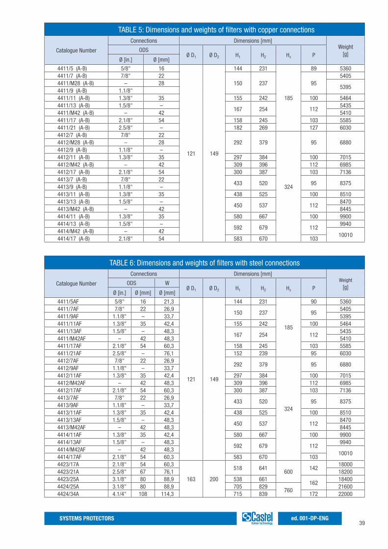
TABLE 5: Dimensions and weights of filters with copper connections
Catalogue Number
Connections Dimensions [mm]Weight
[g]ODS
Ø D1 Ø D2 H1 H2 H3 PØ [in.] Ø [mm]
4411/5 (A-B) 5/8" 16
121 149
144 231
185
89 53604411/7 (A-B) 7/8" 22
150 237 955405
4411/M28 (A-B) – 285395
4411/9 (A-B) 1.1/8"4411/11 (A-B) 1.3/8" 35 155 242 100 54644411/13 (A-B) 1.5/8" –
167 254 1125435
4411/M42 (A-B) – 42 54104411/17 (A-B) 2.1/8" 54 158 245 103 55854411/21 (A-B) 2.5/8" – 182 269 127 60304412/7 (A-B) 7/8" 22
292 379
324
95 68804412/M28 (A-B) – 284412/9 (A-B) 1.1/8" –4412/11 (A-B) 1.3/8" 35 297 384 100 70154412/M42 (A-B) – 42 309 396 112 69854412/17 (A-B) 2.1/8" 54 300 387 103 71364413/7 (A-B) 7/8" 22
433 520 95 83754413/9 (A-B) 1.1/8" –4413/11 (A-B) 1.3/8" 35 438 525 100 85104413/13 (A-B) 1.5/8" –
450 537 1128470
4413/M42 (A-B) – 42 84454414/11 (A-B) 1.3/8" 35 580 667 100 99004414/13 (A-B) 1.5/8" –
592 679 1129940
4414/M42 (A-B) – 4210010
4414/17 (A-B) 2.1/8" 54 583 670 103
TABLE 6: Dimensions and weights of filters with steel connections
Catalogue Number
Connections Dimensions [mm]Weight
[g]ODS W
Ø D1 Ø D2 H1 H2 H3 PØ [in.] Ø [mm] Ø [mm]
4411/5AF 5/8" 16 21,3
121 149
144 231
185
90 53604411/7AF 7/8" 22 26,9
150 237 955405
4411/9AF 1.1/8" – 33,7 53954411/11AF 1.3/8" 35 42,4 155 242 100 54644411/13AF 1.5/8" – 48,3
167 254 1125435
4411/M42AF – 42 48,3 54104411/17AF 2.1/8" 54 60,3 158 245 103 55854411/21AF 2.5/8" – 76,1 152 239 95 60304412/7AF 7/8" 22 26,9
292 379
324
95 68804412/9AF 1.1/8" – 33,74412/11AF 1.3/8" 35 42,4 297 384 100 70154412/M42AF – 42 48,3 309 396 112 69854412/17AF 2.1/8" 54 60,3 300 387 103 71364413/7AF 7/8" 22 26,9
433 520 95 83754413/9AF 1.1/8" – 33,74413/11AF 1.3/8" 35 42,4 438 525 100 85104413/13AF 1.5/8" – 48,3
450 537 1128470
4413/M42AF – 42 48,3 84454414/11AF 1.3/8" 35 42,4 580 667 100 99004414/13AF 1.5/8" – 48,3
592 679 1129940
4414/M42AF – 42 48,310010
4414/17AF 2.1/8" 54 60,3 583 670 1034423/17A 2.1/8" 54 60,3
163 200
518 641600
14218000
4423/21A 2.5/8" 67 76,1 182004423/25A 3.1/8" 80 88,9 538 661
16218400
4424/25A 3.1/8" 80 88,9 705 829760
216004424/34A 4.1/4" 108 114,3 715 839 172 22000

40SYSTEMS PROTECTORSed. 001-DP-ENG
41SYSTEMS PROTECTORS ed. 001-DP-ENG
MECHANICAL FILTERS WITH REPLACEABLE FILTERING BLOCK
Approved by Underwriters Laboratories Inc.
APPLICATIONSThe filters, shown in this chapter, are classified “Pressure vessels” in the sense of the Pressure Equipment Directive 94/23/EC, Article 1, Section 2.1.1 and are subject of Article 3, Section 1.1 of the same Directive.They are designed for installation on commercial refrigerating systems and on civil and industrial conditioning plants, which use the following refrigerant fluids: R22, R134a, R404A, R407C, R410A; R507 proper to the Group II (as defined in Article 9, Section 2.2 of Directive 97/23/EC and referred to in Directive 67/548/EEC). For specific applications with refrigerant fluids not listed above, always proper to the Group II, please contact Castel Technical Department.
OPERATIONGood filtering of the refrigerant on the low-pressure side of the system is a guarantee of protection for the compressor. System cleanliness is ensured by micro filtering cores, which filter out impurities derived from manufacture and assembly of the refrigerating system
CONSTRUCTIONThe filters type 4410 are manufactured with steel body and solder connections:- manufactured with EN 12735-1 – Cu-DHP copper tube (no suffix after connection code)- machined with a steel bar EN 10025 S355JR. (“F” suffix after connection code)The filters type 4420 are completely manufactured in steel and solder connection are machined with a steel bar EN 10025 S355JR.Zinc plated wire cloths and a filtering baffle form the block, which features a large surface, with controlled porosity. The block can stop solid particles up to 20 micron. At the two ends, soft felt gaskets ensure perfect sealing with the plastic cups.Filters 4411 and 4421 , with “C” suffix, are equipped with 1/4” NPT threaded cover and access fitting with valve core G9150/R05.
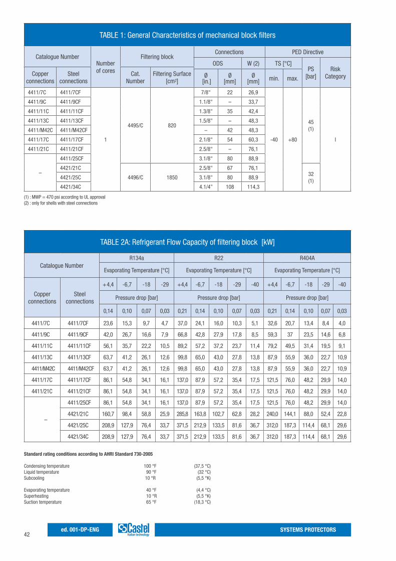
42SYSTEMS PROTECTORSed. 001-DP-ENG
TABLE 1: General Characteristics of mechanical block filters
Catalogue NumberNumber of cores
Filtering blockConnections PED Directive
ODS W (2) TS [°C]PS
[bar]Risk
CategoryCopper connections
Steel connections
Cat. Number
Filtering Surface [cm2]
Ø [in.]
Ø [mm]
Ø [mm] min. max.
4411/7C 4411/7CF
1
4495/C 820
7/8" 22 26,9
-40 +80
45(1)
I
4411/9C 4411/9CF 1.1/8" – 33,7
4411/11C 4411/11CF 1.3/8" 35 42,4
4411/13C 4411/13CF 1.5/8" – 48,3
4411/M42C 4411/M42CF – 42 48,3
4411/17C 4411/17CF 2.1/8" 54 60,3
4411/21C 4411/21CF 2.5/8" – 76,1
–
4411/25CF 3.1/8" 80 88,9
4421/21C
4496/C 1850
2.5/8" 67 76,132(1)
4421/25C 3.1/8" 80 88,9
4421/34C 4.1/4” 108 114,3
(1) : MWP = 470 psi according to UL approval (2) : only for shells with steel connections
TABLE 2A: Refrigerant Flow Capacity of filtering block [kW]
Catalogue NumberR134a R22 R404A
Evaporating Temperature [°C] Evaporating Temperature [°C] Evaporating Temperature [°C]
Copper connections
Steel connections
+ 4,4 -6,7 -18 -29 + 4,4 -6,7 -18 -29 -40 + 4,4 -6,7 -18 -29 -40
Pressure drop [bar] Pressure drop [bar] Pressure drop [bar]
0,14 0,10 0,07 0,03 0,21 0,14 0,10 0,07 0,03 0,21 0,14 0,10 0,07 0,03
4411/7C 4411/7CF 23,6 15,3 9,7 4,7 37,0 24,1 16,0 10,3 5,1 32,6 20,7 13,4 8,4 4,0
4411/9C 4411/9CF 42,0 26,7 16,6 7,9 66,8 42,8 27,9 17,8 8,5 59,3 37 23,5 14,6 6,8
4411/11C 4411/11CF 56,1 35,7 22,2 10,5 89,2 57,2 37,2 23,7 11,4 79,2 49,5 31,4 19,5 9,1
4411/13C 4411/13CF 63,7 41,2 26,1 12,6 99,8 65,0 43,0 27,8 13,8 87,9 55,9 36,0 22,7 10,9
4411/M42C 4411/M42CF 63,7 41,2 26,1 12,6 99,8 65,0 43,0 27,8 13,8 87,9 55,9 36,0 22,7 10,9
4411/17C 4411/17CF 86,1 54,8 34,1 16,1 137,0 87,9 57,2 35,4 17,5 121,5 76,0 48,2 29,9 14,0
4411/21C 4411/21CF 86,1 54,8 34,1 16,1 137,0 87,9 57,2 35,4 17,5 121,5 76,0 48,2 29,9 14,0
–
4411/25CF 86,1 54,8 34,1 16,1 137,0 87,9 57,2 35,4 17,5 121,5 76,0 48,2 29,9 14,0
4421/21C 160,7 98,4 58,8 25,9 285,8 163,8 102,7 62,8 28,2 240,0 144,1 88,0 52,4 22,8
4421/25C 208,9 127,9 76,4 33,7 371,5 212,9 133,5 81,6 36,7 312,0 187,3 114,4 68,1 29,6
4421/34C 208,9 127,9 76,4 33,7 371,5 212,9 133,5 81,6 36,7 312,0 187,3 114,4 68,1 29,6
Standard rating conditions according to AHRI Standard 730-2005 Condensing temperature 100 °F (37,5 °C) Liquid temperature 90 °F (32 °C) Subcooling 10 °R (5,5 °K) Evaporating temperature 40 °F (4,4 °C) Superheating 10 °R (5,5 °K) Suction temperature 65 °F (18,3 °C)
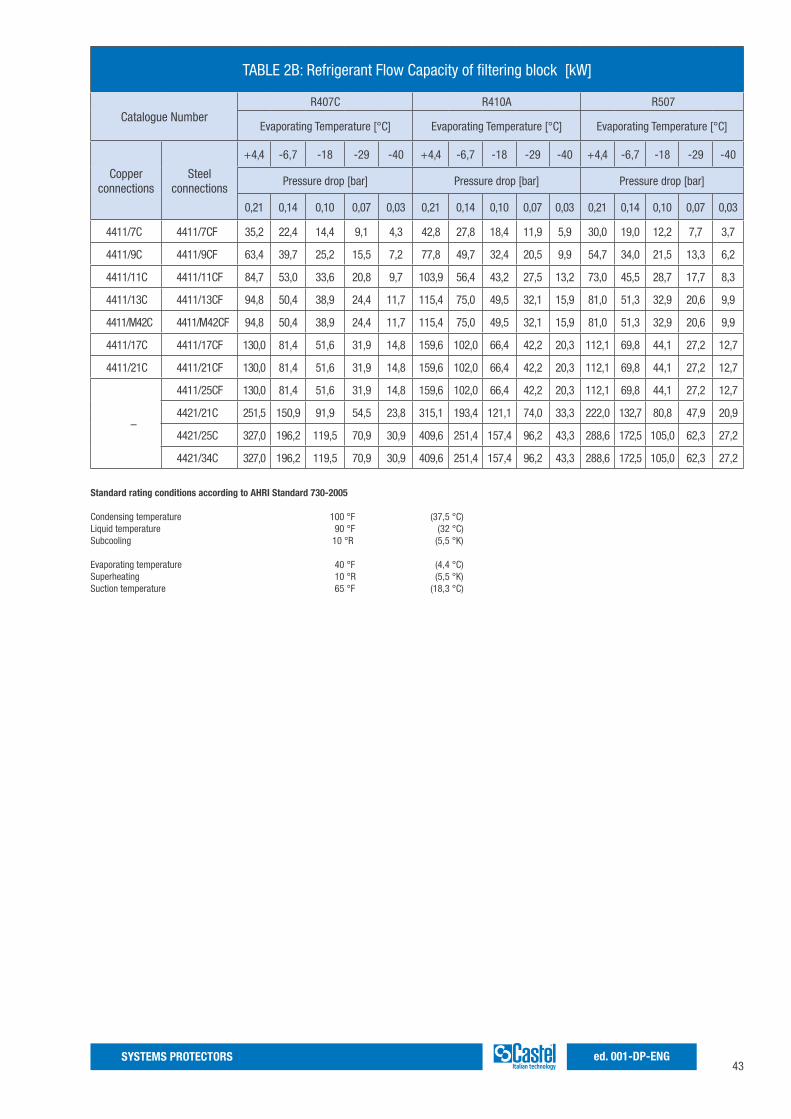
43SYSTEMS PROTECTORS ed. 001-DP-ENG
TABLE 2B: Refrigerant Flow Capacity of filtering block [kW]
Catalogue NumberR407C R410A R507
Evaporating Temperature [°C] Evaporating Temperature [°C] Evaporating Temperature [°C]
Copper connections
Steel connections
+ 4,4 -6,7 -18 -29 -40 + 4,4 -6,7 -18 -29 -40 + 4,4 -6,7 -18 -29 -40
Pressure drop [bar] Pressure drop [bar] Pressure drop [bar]
0,21 0,14 0,10 0,07 0,03 0,21 0,14 0,10 0,07 0,03 0,21 0,14 0,10 0,07 0,03
4411/7C 4411/7CF 35,2 22,4 14,4 9,1 4,3 42,8 27,8 18,4 11,9 5,9 30,0 19,0 12,2 7,7 3,7
4411/9C 4411/9CF 63,4 39,7 25,2 15,5 7,2 77,8 49,7 32,4 20,5 9,9 54,7 34,0 21,5 13,3 6,2
4411/11C 4411/11CF 84,7 53,0 33,6 20,8 9,7 103,9 56,4 43,2 27,5 13,2 73,0 45,5 28,7 17,7 8,3
4411/13C 4411/13CF 94,8 50,4 38,9 24,4 11,7 115,4 75,0 49,5 32,1 15,9 81,0 51,3 32,9 20,6 9,9
4411/M42C 4411/M42CF 94,8 50,4 38,9 24,4 11,7 115,4 75,0 49,5 32,1 15,9 81,0 51,3 32,9 20,6 9,9
4411/17C 4411/17CF 130,0 81,4 51,6 31,9 14,8 159,6 102,0 66,4 42,2 20,3 112,1 69,8 44,1 27,2 12,7
4411/21C 4411/21CF 130,0 81,4 51,6 31,9 14,8 159,6 102,0 66,4 42,2 20,3 112,1 69,8 44,1 27,2 12,7
–
4411/25CF 130,0 81,4 51,6 31,9 14,8 159,6 102,0 66,4 42,2 20,3 112,1 69,8 44,1 27,2 12,7
4421/21C 251,5 150,9 91,9 54,5 23,8 315,1 193,4 121,1 74,0 33,3 222,0 132,7 80,8 47,9 20,9
4421/25C 327,0 196,2 119,5 70,9 30,9 409,6 251,4 157,4 96,2 43,3 288,6 172,5 105,0 62,3 27,2
4421/34C 327,0 196,2 119,5 70,9 30,9 409,6 251,4 157,4 96,2 43,3 288,6 172,5 105,0 62,3 27,2
Standard rating conditions according to AHRI Standard 730-2005 Condensing temperature 100 °F (37,5 °C) Liquid temperature 90 °F (32 °C) Subcooling 10 °R (5,5 °K) Evaporating temperature 40 °F (4,4 °C) Superheating 10 °R (5,5 °K) Suction temperature 65 °F (18,3 °C)

44SYSTEMS PROTECTORSed. 001-DP-ENG
TABLE 3: Dimensions and weights of filters with copper connections
Catalogue Number
Connections Dimensions [mm]Weight
[g]ODS
Ø D1 Ø D2 H1 H2 H3 PØ [in.] Ø [mm]
4411/7C 7/8" 22
121 149
150 237
185
955450
4411/9C 1.1/8" – 5375
4411/11C 1.3/8" 35 155 242 100 5435
4411/13C 1.5/8" –167 254 112 5410
4411/M42C – 42
4411/17C 2.1/8" 54 158 245 103 5585
4411/21C 2.5/8" – 182 269 127 6030
TABLE 4: Dimensions and weights of filters with steel connections
Catalogue Number
Connections Dimensions [mm]Weight
[g]ODS W
Ø D1 Ø D2 H1 H2 H3 PØ [in.] Ø [mm] Ø [mm]
4411/7CF 7/8" 22 26,9
121 149
150 237
185
955450
4411/9CF 1.1/8" – 33,7 5375
4411/11CF 1.3/8" 35 42,4 155 242 100 5435
4411/13CF 1.5/8" – 48,3167 254 112 5410
4411/M42CF – 42 48,3
4411/17CF 2.1/8" 54 60,3 158 245 103 5585
4411/21CF 2.5/8" – 76,1 152 239 95 6030
4411/25CF 3.1/8" 80 88,9 172 259 103 6100
4421/21C 2.5/8" 67 76,1
163 200
187 308
200
142 12000
4421/25C 3.1/8" 80 88,9 205 328 162 12200
4421/34C 4.1/4" 108 114,3 215 338 172 12500
TABLE 5: General Characteristic, Dimensions and Weights of mechanical block
Catalogue NumberFiltering Surface Dimensioni [mm] Weight
[g]Ø [in.] Ø [mm] Ø D1 Ø D2 H1
4495/C 127 820 60 87 138 480
4496/C 287 1850 80 113 168 750
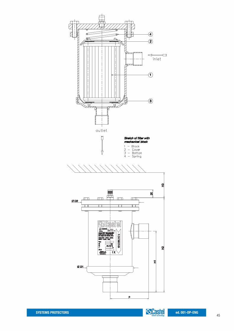
45SYSTEMS PROTECTORS ed. 001-DP-ENG
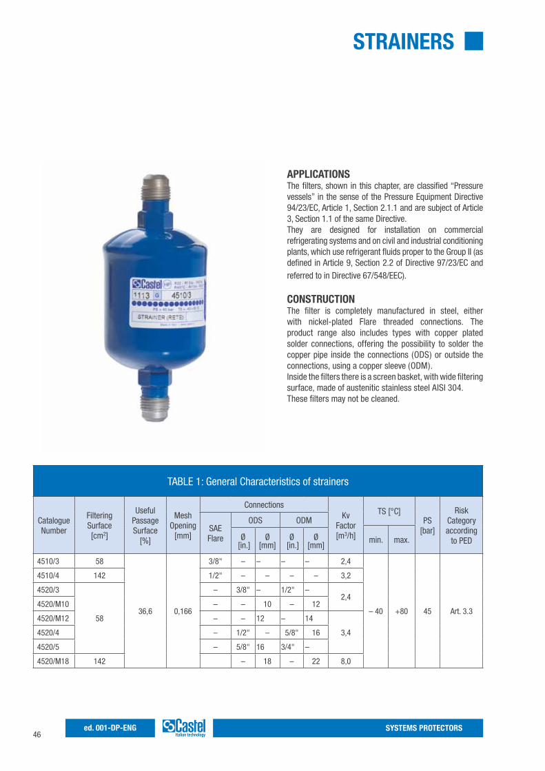
46SYSTEMS PROTECTORSed. 001-DP-ENG
STRAINERS
APPLICATIONSThe filters, shown in this chapter, are classified “Pressure vessels” in the sense of the Pressure Equipment Directive 94/23/EC, Article 1, Section 2.1.1 and are subject of Article 3, Section 1.1 of the same Directive.They are designed for installation on commercial refrigerating systems and on civil and industrial conditioning plants, which use refrigerant fluids proper to the Group II (as defined in Article 9, Section 2.2 of Directive 97/23/EC and referred to in Directive 67/548/EEC).
CONSTRUCTIONThe filter is completely manufactured in steel, either with nickel-plated Flare threaded connections. The product range also includes types with copper plated solder connections, offering the possibility to solder the copper pipe inside the connections (ODS) or outside the connections, using a copper sleeve (ODM).Inside the filters there is a screen basket, with wide filtering surface, made of austenitic stainless steel AISI 304.These filters may not be cleaned.
TABLE 1: General Characteristics of strainers
CatalogueNumber
Filtering Surface[cm2]
Useful Passage Surface
[%]
Mesh Opening
[mm]
ConnectionsKv
Factor[m3/h]
TS [°C]PS
[bar]
Risk Category according
to PEDSAE Flare
ODS ODM
min. max.Ø [in.]
Ø [mm]
Ø [in.]
Ø [mm]
4510/3 58
36,6 0,166
3/8" – – – – 2,4
– 40 +80 45 Art. 3.3
4510/4 142 1/2" – – – – 3,2
4520/3
58
– 3/8" – 1/2" –2,4
4520/M10 – – 10 – 12
4520/M12 – – 12 – 14
3,44520/4 – 1/2" – 5/8" 16
4520/5 – 5/8" 16 3/4" –
4520/M18 142 – 18 – 22 8,0
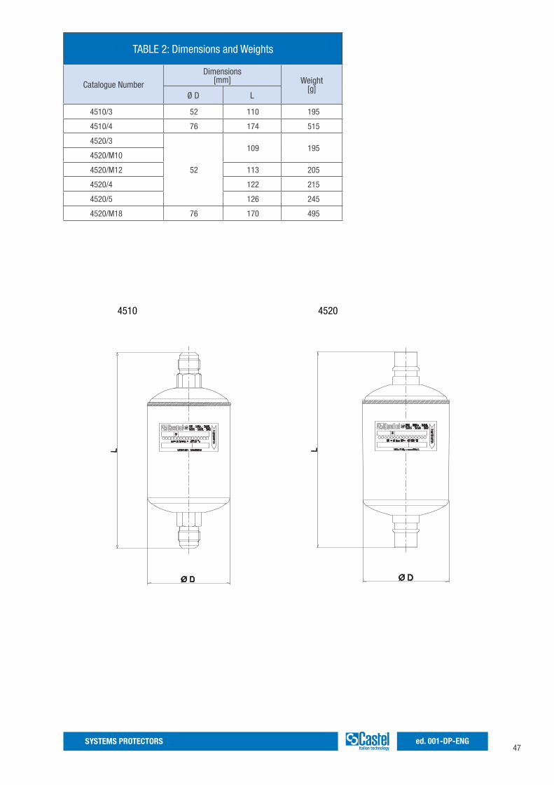
47SYSTEMS PROTECTORS ed. 001-DP-ENG
TABLE 2: Dimensions and Weights
Catalogue Number
Dimensions[mm] Weight
[g]Ø D L
4510/3 52 110 195
4510/4 76 174 515
4520/3
52
109 1954520/M10
4520/M12 113 205
4520/4 122 215
4520/5 126 245
4520/M18 76 170 495
4510 4520

SYSTEMS PROTECTORSed. 001-DP-ENG
www.castel.it
ed. 001-DP-ENG Castel Srl - Via Provinciale 2-4 - 20060 Pessano con Bornago - MI
Castel can accept no responsibility for any errors or changes in the catalogues, handbooks, brochures and other printed material. Castel reserves the right to make changes and improvements to its products without notice. All trademarks mentioned are the property of their respective owners. The name and Castel logotype are registered trademarks of Castel Srl. All rights reserved.