Embed Size (px)
Citation preview

REFERENCES, GRIDS, & GEOMETRY

REFERENCE:
1. the use of a source of information in order to ascertain something.
2. a relation between objects in which one object designates, or acts as a means by which to connect to or link to, another object.
REMEMBER: Always try to start big with the largest overall reference points and work your way down in scale to the smaller details
POINT LINE PLANE
3 SAMPLE LOTS
Assume that we have had these lots surveyed by a professional surveyor, so we know the overall dimensions and orientation of each lot

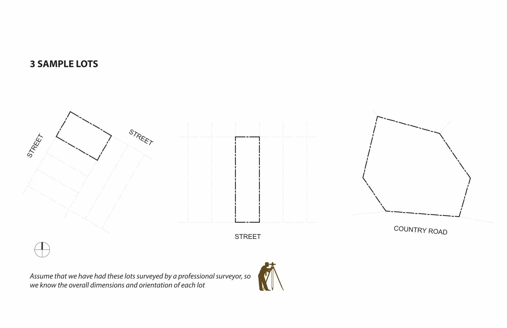
SURVEY EXAMPLES
SURVEY EXAMPLES

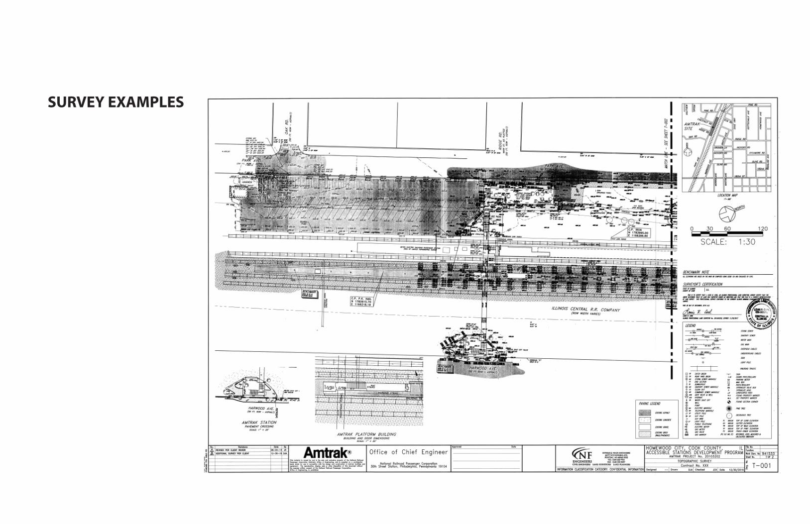
LOT 1
Site Restrictions:
• There are
no setback
requirements
• Building may
occupy entire lot
LOT 1 BUILDING
Building Size:
30’ wide x 50’ long

LOT 2
Site Restrictions:
• 10’ minimum
required setback
at the front
(street side) lot
line
• 30’ minimum
required setback
at the rear lot
line
• No setbacks
required at side
lot lines

LOT 2 BUILDING
Building Size:
25’ wide x 50’ long

LOT 3
Site Restrictions:
• No restrictions,
building can be
placed anywhere
on the site

NEW BUILDING GRID
& ENVELOPE
Designed by you
- the architect - to
meet the client’s
needs

LOT 3 BUILDING
Site Design:
• Building must
be oriented this
way in order to
maximize views
on the site
• How do you
convey this
information
accurately to the
contractor so
that he can lay
the building out
properly on site?

REFERENCE POINTS
(CONTROL POINTS)
What do we know?
• The lot has been
surveyed, so we
know where all of
the lot lines are
• We also know
where north,
south, east, and
west are
• Using our
drafting
software, we can
locate the corner
of our building
in relation to a
given point

BUILDING LOCATION
Convey
Information:
• Using our
survey points
and cardinal
directions, we
can identify
precisely the
location and
orientation of
our building
on the site, and
present that
information
clearly to the
contractor
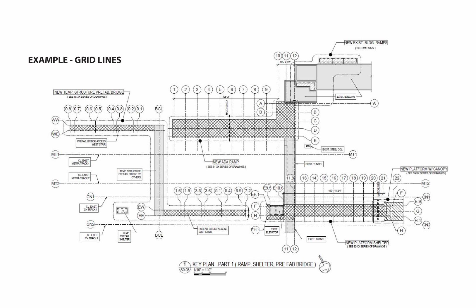
EXAMPLE - GRID LINES

GRID LINES

GRID LINES

EXAMPLE - GRID LINES, LEVELS, & SCALE

BUILDING GEOMETRY
Marina City:
• Using the Marina City
towers in Chicago as
an example, we will
look at how a building’s
structural grid and plan
geometry can be used
to organize program
(and vice versa)

BUILDING GEOMETRY - PLAN
Structure vs Space:
• Structural elements do not
fi t in a simple orthogonal
grid, but there is a clear
organizational geometry
here that we can identify...

BUILDING GEOMETRY - PLAN
Grid Lines:
• By studying the plan, we
can identify the grids which
organize the structural
elements
• This design uses radial
geometries (rather than
orthogonal) to lay out the
building elements in plan

BUILDING GEOMETRY - PLAN
Program Zones:
• The architect for this building
used the structural grid and
plan geometries to organize
the building’s program into
zones
Core / Utilities:
Circulation:
Residential:

BUILDING GEOMETRY - PLAN
Unit Layouts:
• The architect also used the
structural grid and plan
geometries to organize the
individual residential units
• All units terminate at a
structural grid line, or the
halfway point between 2
structural grid lines

LET’S TRY ONE TOGETHER...
Recognize this building?
• Let’s start by trying to fi gure
out the structural grid

LET’S TRY ONE TOGETHER...
Structural Grid
• Pay attention to structural
elements for clues
• Notice any irregularities?
Make sure to account for
them
• Overall this grid is pretty
simple
• Now let’s look for program
zones...

LET’S TRY ONE TOGETHER...
Program Zones
• Do the structural grid and
plan geometries correspond
in any way to the program
zones?
• Are there irregularities?
Core / Utilities:
Circulation:
Class / Offi ce:

LET’S TRY ONE TOGETHER...
Geometry Diagram
• Use what we’ve learned
analyzing the plan to create a
plan geometry diagram

APPLICATION TO FEDERAL HALL PLANS...

START BIG, LOCATE REFERENCES

ESTABLISH GRID BASED ON REFERENCE DIMENSIONS

IDENTIFY ANOMALIES / CREATE REFERENCE (CENTER) LINES
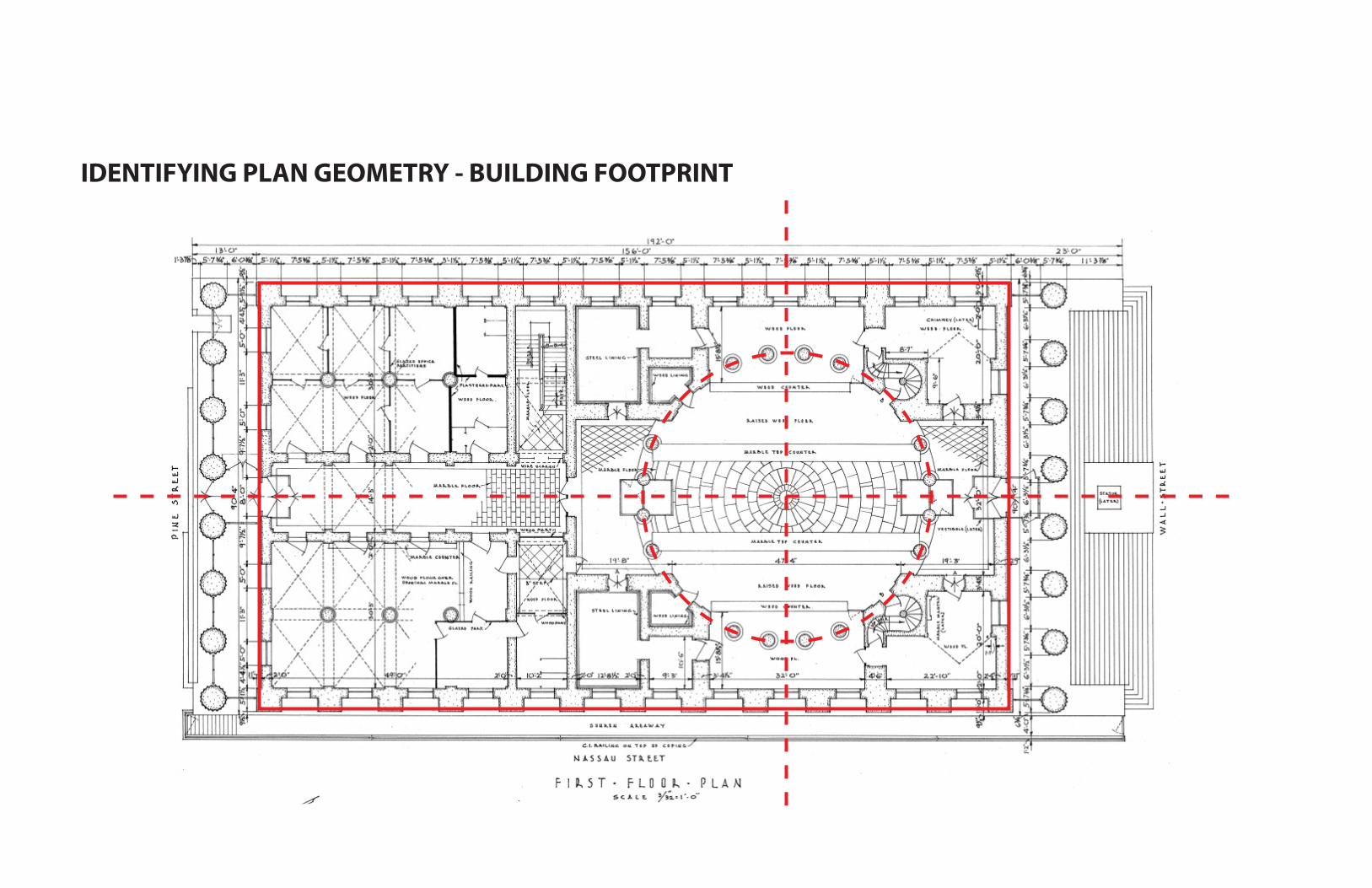
IDENTIFYING PLAN GEOMETRY - BUILDING FOOTPRINT

IDENTIFYING PLAN GEOMETRY - KEY OFFSETS / PROGRAM ZONES

IDENTIFYING PLAN GEOMETRY - BLOCKING / GEOMETRY

GEOMETRY DIAGRAM

APPLICATION TO FEDERAL HALL...

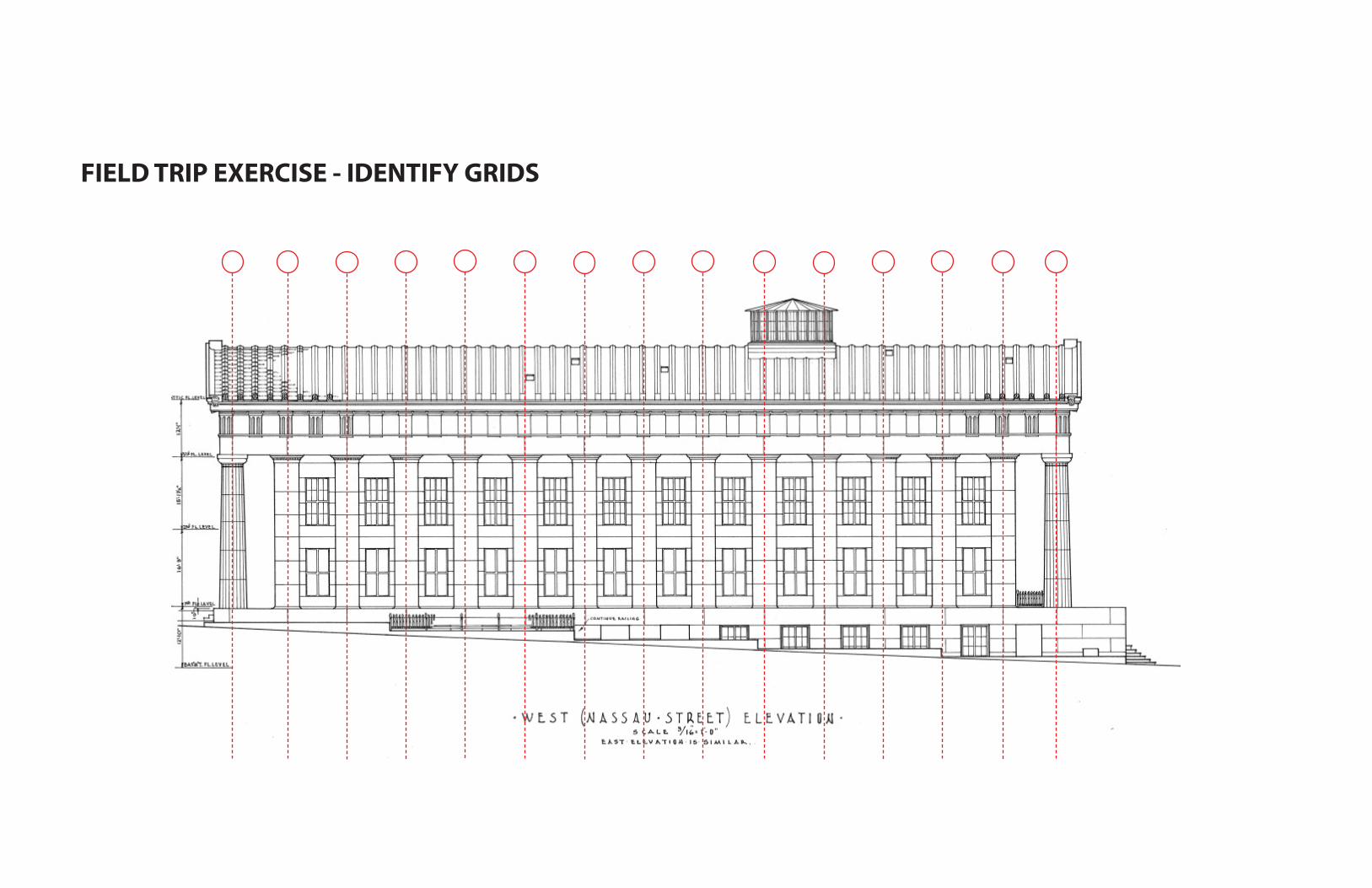
FIELD TRIP EXERCISE - IDENTIFY GRIDS

FIELD TRIP EXERCISE - IDENTIFY LEVELS / ZONES

FIELD TRIP EXERCISE - IDENTIFY KEY GEOMETRIES

GEOMETRY DIAGRAM
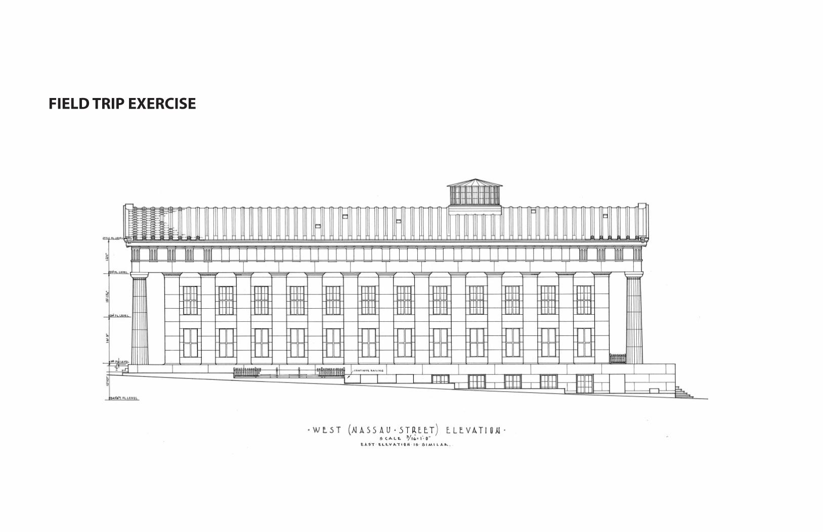
FIELD TRIP EXERCISE
FIELD TRIP EXERCISE - IDENTIFY GRIDS

FIELD TRIP EXERCISE - IDENTIFY LEVELS / ZONES

FIELD TRIP EXERCISE - IDENTIFY LEVELS / ZONES


![Big line bundles over arithmetic varietiesyxy/preprints/big.pdf · 606 X. Yuan Arakelov geometry. The basic references for Arakelov geometry are [Ar], [Fa], [GS1] and [Zh1]. Let K](https://img.pdfslide.us/doc/110x75/5ed836800fa3e705ec0e0ba8/big-line-bundles-over-arithmetic-varieties-yxypreprintsbigpdf-606-x-yuan-arakelov.jpg)