Embed Size (px)
Citation preview
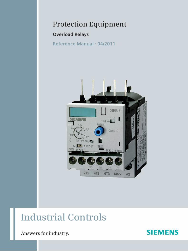
Protection EquipmentOverload Relays
Reference Manual • 04/2011
Industrial Controls
Answers for industry.

Siemens · 2011
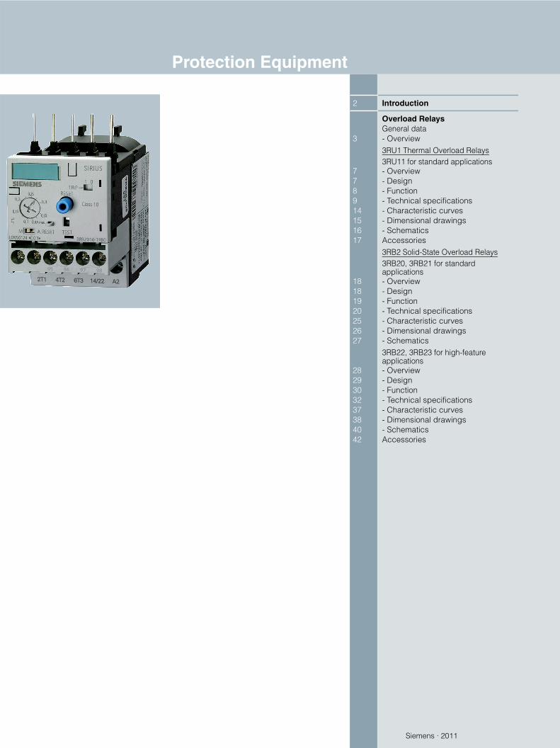
2 Introduction
Overload RelaysGeneral data
3 - Overview3RU1 Thermal Overload Relays3RU11 for standard applications
7 - Overview7 - Design8 - Function9 - Technical specifications14 - Characteristic curves15 - Dimensional drawings16 - Schematics17 Accessories
3RB2 Solid-State Overload Relays3RB20, 3RB21 for standard applications
18 - Overview18 - Design19 - Function20 - Technical specifications25 - Characteristic curves26 - Dimensional drawings27 - Schematics
3RB22, 3RB23 for high-feature applications
28 - Overview29 - Design30 - Function32 - Technical specifications37 - Characteristic curves38 - Dimensional drawings40 - Schematics42 Accessories
Protection Equipment
Protection Equipment
Introduction
2 Siemens · 2011
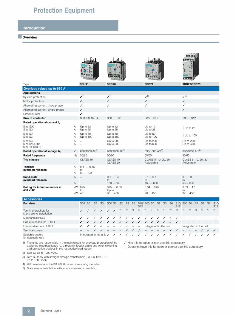
■ Overview
1) The units are responsible in the main circuit for overload protection of the assigned electrical loads (e. g.motors), feeder cable and other switching and protection devices in the respective load feeder.
2) Size S3 up to 1000 V AC.
3) Size S2 (only with straight-through transformer), S3, S6, S10, S12up to 1000 V AC.
4) With reference to the 3RB29 .6 current measuring modules.
5) Stand-alone installation without accessories is possible.
✓ Has this function or can use this accessory-- Does not have this function or cannot use this accessory
Type 3RU11 3RB20 3RB21 3RB22/3RB23
Overload relays up to 630 A Applications
System protection ✓1) ✓1) ✓1) ✓1)
Motor protection ✓ ✓ ✓ ✓
Alternating current, three-phase ✓ ✓ ✓ ✓
Alternating current, single-phase ✓ -- -- ✓
Direct current ✓ -- -- --
Size of contactor S00, S0, S2, S3 S00 ... S12 S00 ... S12 S00 ... S12
Rated operational current Ie
Size S00Size S0
AA
Up to 12Up to 25
Up to 12Up to 25
Up to 12Up to 25 } Up to 25
Size S2Size S3
AA
Up to 50Up to 100
Up to 50Up to 100
Up to 50Up to 100 } Up to 100
Size S6Size S10/S12, Size 14 (3TF6)
AA
----
Up to 200Up to 630
Up to 200Up to 630
Up to 200Up to 630
Rated operational voltage Ue V 690/1000 AC2) 690/1000 AC3) 690/1000 AC3) 690/1000 AC4)
Rated frequency Hz 50/60 50/60 50/60 50/60
Trip classes CLASS 10 CLASS 10, CLASS 20
CLASS 5, 10, 20, 30 Adjustable
CLASS 5, 10, 20, 30 Adjustable
Thermal overload releases
A
A
0.11 ... 0.16 to80 ... 100
-- -- --
Solid-state overload releases
A
A
-- 0.1 ... 0.4 to160 ... 630
0.1 ... 0.4 to160 ... 630
0.3 ... 3 to63 ... 630
Rating for induction motor at 400 V AC
kW
kW
0.04 to 45
0.04 ... 0.09 Up to90 ... 450
0.04 ... 0.09 to90 ... 450
0.09 ... 1.1 to37 ... 450
AccessoriesFor sizes S00 S0 S2 S3 S00 S0 S2 S3 S6 S10/
S12S00 S0 S2 S3 S6 S10/
S12S00 S0 S2 S3 S6 S10/
S12
Terminal brackets for stand-alone installation
✓ ✓ ✓ ✓ ✓ ✓ 5) 5) 5) 5) ✓ ✓ 5) 5) 5) 5) 5) 5) 5) 5) 5) 5)
Mechanical RESET ✓ ✓ ✓ ✓ ✓ ✓ ✓ ✓ ✓ ✓ ✓ ✓ ✓ ✓ ✓ ✓ -- -- -- -- -- --
Cable releases for RESET ✓ ✓ ✓ ✓ ✓ ✓ ✓ ✓ ✓ ✓ ✓ ✓ ✓ ✓ ✓ ✓ -- -- -- -- -- --
Electrical remote RESET ✓ ✓ ✓ ✓ -- -- -- -- -- -- Integrated in the unit Integrated in the unit
Terminal covers -- -- ✓ ✓ -- -- -- ✓ ✓ ✓ -- -- -- ✓ ✓ ✓ -- -- -- ✓ ✓ ✓
Sealable coversfor setting knobs
Integrated in the unit ✓ ✓ ✓ ✓ ✓ ✓ ✓ ✓ ✓ ✓ ✓ ✓ ✓ ✓ ✓ ✓ ✓ ✓
Overload Relays
3Siemens · 2011
General data
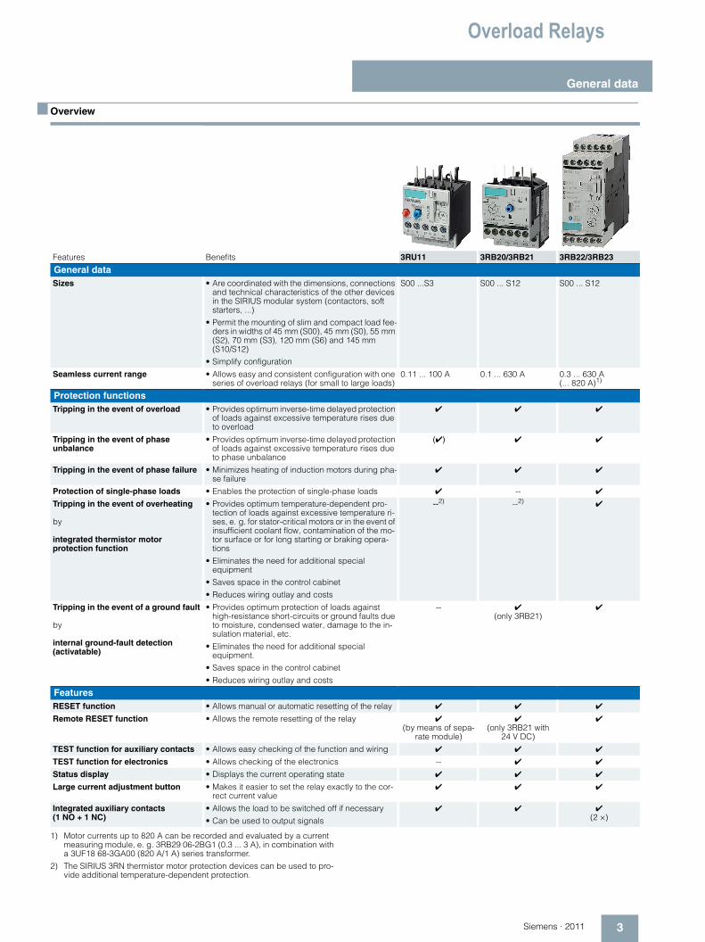
■ Overview
1) Motor currents up to 820 A can be recorded and evaluated by a current measuring module, e. g. 3RB29 06-2BG1 (0.3 ... 3 A), in combination with a 3UF18 68-3GA00 (820 A/1 A) series transformer.
2) The SIRIUS 3RN thermistor motor protection devices can be used to pro-vide additional temperature-dependent protection.
Features Benefits 3RU11 3RB20/3RB21 3RB22/3RB23
General dataSizes • Are coordinated with the dimensions, connections
and technical characteristics of the other devices in the SIRIUS modular system (contactors, soft starters, ...)
• Permit the mounting of slim and compact load fee-ders in widths of 45 mm (S00), 45 mm (S0), 55 mm (S2), 70 mm (S3), 120 mm (S6) and 145 mm (S10/S12)
• Simplify configuration
S00 ...S3 S00 ... S12 S00 ... S12
Seamless current range • Allows easy and consistent configuration with one series of overload relays (for small to large loads)
0.11 ... 100 A 0.1 ... 630 A 0.3 ... 630 A (... 820 A)1)
Protection functionsTripping in the event of overload • Provides optimum inverse-time delayed protection
of loads against excessive temperature rises due to overload
✔ ✔ ✔
Tripping in the event of phase unbalance
• Provides optimum inverse-time delayed protection of loads against excessive temperature rises due to phase unbalance
(✔) ✔ ✔
Tripping in the event of phase failure • Minimizes heating of induction motors during pha-se failure
✔ ✔ ✔
Protection of single-phase loads • Enables the protection of single-phase loads ✔ -- ✔
Tripping in the event of overheating
by
integrated thermistor motor protection function
• Provides optimum temperature-dependent pro-tection of loads against excessive temperature ri-ses, e. g. for stator-critical motors or in the event of insufficient coolant flow, contamination of the mo-tor surface or for long starting or braking opera-tions
• Eliminates the need for additional special equipment
• Saves space in the control cabinet
• Reduces wiring outlay and costs
--2) --2) ✔
Tripping in the event of a ground fault
by
internal ground-fault detection (activatable)
• Provides optimum protection of loads against high-resistance short-circuits or ground faults due to moisture, condensed water, damage to the in-sulation material, etc.
• Eliminates the need for additional special equipment.
• Saves space in the control cabinet
• Reduces wiring outlay and costs
-- ✔(only 3RB21)
✔
FeaturesRESET function • Allows manual or automatic resetting of the relay ✔ ✔ ✔
Remote RESET function • Allows the remote resetting of the relay ✔ (by means of sepa-
rate module)
✔ (only 3RB21 with
24 V DC)
✔
TEST function for auxiliary contacts • Allows easy checking of the function and wiring ✔ ✔ ✔
TEST function for electronics • Allows checking of the electronics -- ✔ ✔
Status display • Displays the current operating state ✔ ✔ ✔
Large current adjustment button • Makes it easier to set the relay exactly to the cor-rect current value
✔ ✔ ✔
Integrated auxiliary contacts (1 NO + 1 NC)
• Allows the load to be switched off if necessary
• Can be used to output signals
✔ ✔ ✔(2 ×)
Overload Relays
General data
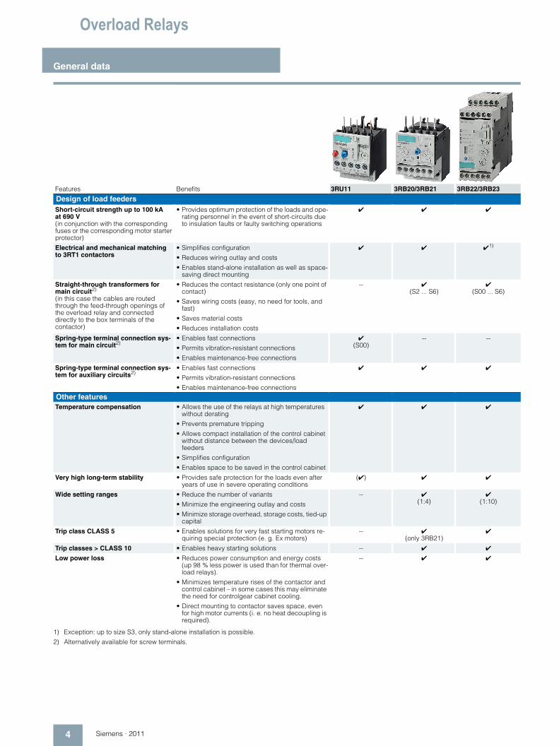
4 Siemens · 2011
1) Exception: up to size S3, only stand-alone installation is possible.
2) Alternatively available for screw terminals.
Features Benefits 3RU11 3RB20/3RB21 3RB22/3RB23
Design of load feedersShort-circuit strength up to 100 kA at 690 V(in conjunction with the corresponding fuses or the corresponding motor starter protector)
• Provides optimum protection of the loads and ope-rating personnel in the event of short-circuits due to insulation faults or faulty switching operations
✔ ✔ ✔
Electrical and mechanical matching to 3RT1 contactors
• Simplifies configuration
• Reduces wiring outlay and costs
• Enables stand-alone installation as well as space-saving direct mounting
✔ ✔ ✔1)
Straight-through transformers for main circuit2)
(in this case the cables are routed through the feed-through openings of the overload relay and connected directly to the box terminals of the contactor)
• Reduces the contact resistance (only one point of contact)
• Saves wiring costs (easy, no need for tools, and fast)
• Saves material costs
• Reduces installation costs
-- ✔(S2 ... S6)
✔(S00 ... S6)
Spring-type terminal connection sys-tem for main circuit2)
• Enables fast connections
• Permits vibration-resistant connections
• Enables maintenance-free connections
✔(S00)
-- --
Spring-type terminal connection sys-tem for auxiliary circuits2)
• Enables fast connections
• Permits vibration-resistant connections
• Enables maintenance-free connections
✔ ✔ ✔
Other featuresTemperature compensation • Allows the use of the relays at high temperatures
without derating
• Prevents premature tripping
• Allows compact installation of the control cabinet without distance between the devices/load feeders
• Simplifies configuration
• Enables space to be saved in the control cabinet
✔ ✔ ✔
Very high long-term stability • Provides safe protection for the loads even after years of use in severe operating conditions
(✔) ✔ ✔
Wide setting ranges • Reduce the number of variants
• Minimize the engineering outlay and costs
• Minimize storage overhead, storage costs, tied-up capital
-- ✔(1:4)
✔(1:10)
Trip class CLASS 5 • Enables solutions for very fast starting motors re-quiring special protection (e. g. Ex motors)
-- ✔(only 3RB21)
✔
Trip classes > CLASS 10 • Enables heavy starting solutions -- ✔ ✔
Low power loss • Reduces power consumption and energy costs (up 98 % less power is used than for thermal over-load relays).
• Minimizes temperature rises of the contactor and control cabinet – in some cases this may eliminate the need for controlgear cabinet cooling.
• Direct mounting to contactor saves space, even for high motor currents (i. e. no heat decoupling is required).
-- ✔ ✔
Overload Relays
5Siemens · 2011
General data
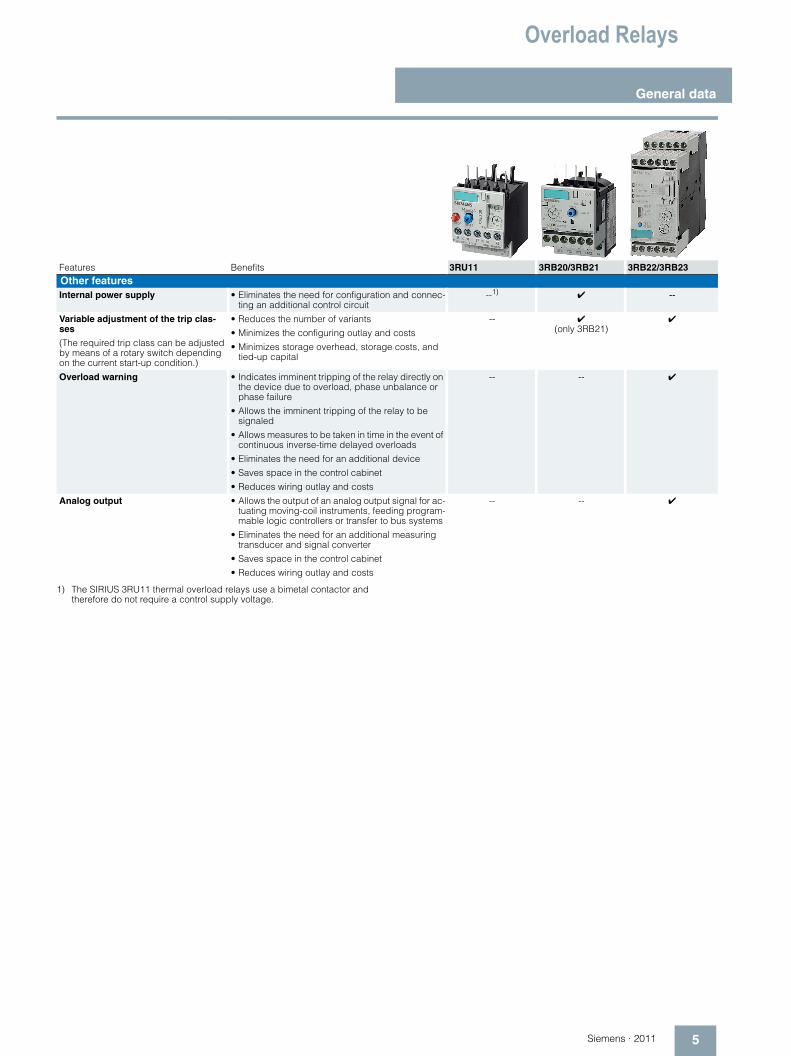
1) The SIRIUS 3RU11 thermal overload relays use a bimetal contactor and therefore do not require a control supply voltage.
Features Benefits 3RU11 3RB20/3RB21 3RB22/3RB23Other featuresInternal power supply • Eliminates the need for configuration and connec-
ting an additional control circuit--1) ✔ --
Variable adjustment of the trip clas-ses
(The required trip class can be adjusted by means of a rotary switch depending on the current start-up condition.)
• Reduces the number of variants
• Minimizes the configuring outlay and costs
• Minimizes storage overhead, storage costs, and tied-up capital
-- ✔(only 3RB21)
✔
Overload warning • Indicates imminent tripping of the relay directly on the device due to overload, phase unbalance or phase failure
• Allows the imminent tripping of the relay to be signaled
• Allows measures to be taken in time in the event of continuous inverse-time delayed overloads
• Eliminates the need for an additional device
• Saves space in the control cabinet
• Reduces wiring outlay and costs
-- -- ✔
Analog output • Allows the output of an analog output signal for ac-tuating moving-coil instruments, feeding program-mable logic controllers or transfer to bus systems
• Eliminates the need for an additional measuring transducer and signal converter
• Saves space in the control cabinet
• Reduces wiring outlay and costs
-- -- ✔
Overload Relays
General data
6 Siemens · 2011
1) When using the overload relays with trip class ≥ CLASS 20, see "Technical specifications", "Short-Circuit Protection with Fuses for Motor Feeders", and the Configuration Manual „SIRIUS Configuration - Selection data for Fuseless Load Feeders“, Order No. 3ZX1012-0RA21-0AC0"or as a PDF file on the Internet athttp://support.automation.siemens.com/WW/view/en/40625241
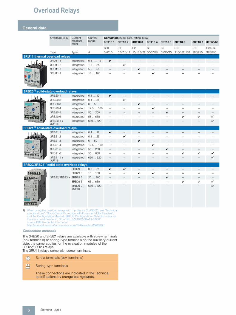
Connection methods
The 3RB20 and 3RB21 relays are available with screw terminals (box terminals) or spring-type terminals on the auxiliary current side; the same applies for the evaluation modules of the 3RB22/3RB23 relays. The 3RU11 relays come with screw terminals.
Overload relay Current measure-ment
Current range
Contactors (type, size, rating in kW)
3RT10 1 3RT10 2 3RT10 3 3RT10 4 3RT10 5 3RT10 6 3RT10 7 3TF68/69
S00 S0 S2 S3 S6 S10 S12 Size 14
Type Type A 3/4/5.5 5.5/7.5/11 15/18.5/22 30/37/45 55/75/90 110/132/160 200/250 375/450
3RU11 thermal overload relays3RU11 1 Integrated 0.11 … 12 ✔ -- -- -- -- -- -- --
3RU11 2 Integrated 1.8 … 25 -- ✔ -- -- -- -- -- --
3RU11 3 Integrated 5.5 … 50 -- -- ✔ -- -- -- -- --
3RU11 4 Integrated 18 … 100 -- -- -- ✔ -- -- -- --
3RB201) solid-state overload relays3RB20 1 Integrated 0.1 … 12 ✔ -- -- -- -- -- -- --
3RB20 2 Integrated 0.1 … 25 -- ✔ -- -- -- -- -- --
3RB20 3 Integrated 6 … 50 -- -- ✔ -- -- -- -- --
3RB20 4 Integrated 12.5 … 100 -- -- -- ✔ -- -- -- --
3RB20 5 Integrated 50 ... 200 -- -- -- -- ✔ -- -- --
3RB20 6 Integrated 55 ... 630 -- -- -- -- -- ✔ ✔ ✔
3RB20 1 + 3UF18
Integrated 630 ... 820 -- -- -- -- -- -- -- ✔
3RB211) solid-state overload relays3RB21 1 Integrated 0.1 … 12 ✔ -- -- -- -- -- -- --
3RB21 2 Integrated 0.1 … 25 -- ✔ -- -- -- -- -- --
3RB21 3 Integrated 6 … 50 -- -- ✔ -- -- -- -- --
3RB21 4 Integrated 12.5 … 100 -- -- -- ✔ -- -- -- --
3RB21 5 Integrated 50 ... 200 -- -- -- -- ✔ -- -- --
3RB21 6 Integrated 55 ... 630 -- -- -- -- -- ✔ ✔ ✔
3RB21 1 + 3UF18
Integrated 630 ... 820 -- -- -- -- -- -- -- ✔
3RB22/3RB231) solid-state overload relays3RB29 0 0.3 … 25 ✔ ✔ -- -- -- -- -- --
3RB29 0 10 ... 100 -- -- ✔ ✔ -- -- -- --
3RB22/3RB23 + 3RB29 5 20 … 200 -- -- -- -- ✔ -- -- --
3RB29 6 63 ... 630 -- -- -- -- -- ✔ ✔ ✔
3RB29 0 + 3UF18
630 ... 820 -- -- -- -- -- -- -- ✔
Screw terminals (box terminals)
Spring-type terminals
These connections are indicated in the Technical specifications by orange backgrounds.
Overload Relays
7Siemens · 2011
3RU1 Thermal Overload Relays
3RU11 for standard applications
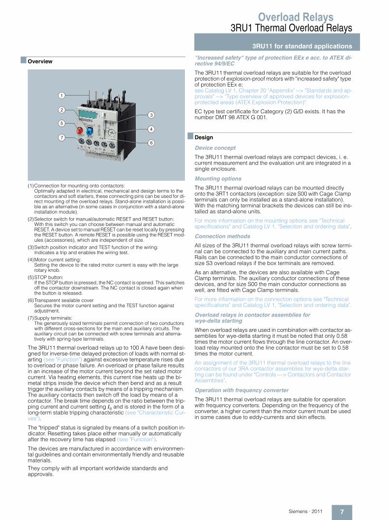
■ Overview
(1)Connection for mounting onto contactors: Optimally adapted in electrical, mechanical and design terms to the contactors and soft starters, these connecting pins can be used for di-rect mounting of the overload relays. Stand-alone installation is possi-ble as an alternative (in some cases in conjunction with a stand-alone installation module).
(2)Selector switch for manual/automatic RESET and RESET button: With this switch you can choose between manual and automatic RESET. A device set to manual RESET can be reset locally by pressing the RESET button. A remote RESET is possible using the RESET mod-ules (accessories), which are independent of size.
(3)Switch position indicator and TEST function of the wiring: Indicates a trip and enables the wiring test.
(4)Motor current setting: Setting the device to the rated motor current is easy with the large rotary knob.
(5)STOP button: If the STOP button is pressed, the NC contact is opened. This switches off the contactor downstream. The NC contact is closed again when the button is released.
(6)Transparent sealable coverSecures the motor current setting and the TEST function against adjustment.
(7)Supply terminals: The generously sized terminals permit connection of two conductors with different cross-sections for the main and auxiliary circuits. The auxiliary circuit can be connected with screw terminals and alterna-tively with spring-type terminals.
The 3RU11 thermal overload relays up to 100 A have been desi-gned for inverse-time delayed protection of loads with normal st-arting (see "Function") against excessive temperature rises due to overload or phase failure. An overload or phase failure results in an increase of the motor current beyond the set rated motor current. Via heating elements, this current rise heats up the bi-metal strips inside the device which then bend and as a result trigger the auxiliary contacts by means of a tripping mechanism. The auxiliary contacts then switch off the load by means of a contactor. The break time depends on the ratio between the trip-ping current and current setting Ie and is stored in the form of a long-term stable tripping characteristic (see "Characteristic Cur-ves").
The "tripped" status is signaled by means of a switch position in-dicator. Resetting takes place either manually or automatically after the recovery time has elapsed (see "Function").
The devices are manufactured in accordance with environmen-tal guidelines and contain environmentally friendly and reusable materials.They comply with all important worldwide standards and approvals.
"Increased safety" type of protection EEx e acc. to ATEX di-rective 94/9/EC
The 3RU11 thermal overload relays are suitable for the overload protection of explosion-proof motors with "increased safety" type of protection EEx e; see Catalog LV 1, Chapter 20 "Appendix" --> "Standards and ap-provals" --> "Type overview of approved devices for explosion-protected areas (ATEX Explosion Protection)".
EC type test certificate for Category (2) G/D exists. It has the number DMT 98 ATEX G 001.
■ Design
Device concept
The 3RU11 thermal overload relays are compact devices, i. e. current measurement and the evaluation unit are integrated in a single enclosure.
Mounting options
The 3RU11 thermal overload relays can be mounted directly onto the 3RT1 contactors (exception: size S00 with Cage Clamp terminals can only be installed as a stand-alone installation). With the matching terminal brackets the devices can still be ins-talled as stand-alone units.
For more information on the mounting options see "Technical specifications" and Catalog LV 1, "Selection and ordering data".
Connection methods
All sizes of the 3RU11 thermal overload relays with screw termi-nal can be connected to the auxiliary and main current paths. Rails can be connected to the main conductor connections of size S3 overload relays if the box terminals are removed.
As an alternative, the devices are also available with Cage Clamp terminals. The auxiliary conductor connections of these devices, and for size S00 the main conductor connections as well, are fitted with Cage Clamp terminals.
For more information on the connection options see "Technical specifications" and Catalog LV 1, "Selection and ordering data".
Overload relays in contactor assemblies for wye-delta starting
When overload relays are used in combination with contactor as-semblies for wye-delta starting it must be noted that only 0.58 times the motor current flows through the line contactor. An over-load relay mounted onto the line contactor must be set to 0.58 times the motor current.
An assignment of the 3RU11 thermal overload relays to the line contactors of our 3RA contactor assemblies for wye-delta star-ting can be found under "Controls ---> Contactors and Contactor Assemblies".
Operation with frequency converter
The 3RU11 thermal overload relays are suitable for operation with frequency converters. Depending on the frequency of the converter, a higher current than the motor current must be used in some cases due to eddy-currents and skin effects.
1
2
5
7
3
4
6
Overload Relays3RU1 Thermal Overload Relays3RU11 for standard applications
8 Siemens · 2011
■ Function
Basic functions
The 3RU11 thermal overload relays are designed for:• Inverse-time delayed protection of loads from overloading• Inverse-time delayed protection of loads from phase failure
Control circuit
The 3RU11 thermal overload relays do not require an additional supply voltage for operation.
Short-circuit protection
Fuses or motor starter protectors must be used for short-circuit protection.
For assignments of the corresponding short-circuit protection de-vices to the 3RU11 thermal overload relays with/without contactor see "Technical specifications" and Catalog LV 1, "Selection and or-dering data".
Trip classes
The 3RU11 thermal overload relays are available for normal star-ting conditions with trip class CLASS 10. For heavy starting con-ditions see 3RB2 solid-state overload relays.
For details of the trip classes see "Characteristic Curves".
Phase failure protection
The 3RU11 thermal overload relays are fitted with phase failure sensitivity (see "Characteristic Curves") in order to minimize tem-perature rises of the load in the case of a phase failure during sin-gle-phase operation.
Setting
The 3RU11 thermal overload relays are set to the rated motor cur-rent by means of a rotary knob. The scale of the rotary knob is shown in ampere.
Manual and automatic reset
Automatic and manual reset is selected by pressing and turning the blue button (RESET button). If the button is set to manual reset, the overload relay can be reset directly by pressing the RESET button. Resetting is possible in combination with mechani-cal and electrical reset options from the range of accessories (see Catalog LV 1, "Accessories"). If the blue button is set to automatic RESET, the relay is reset automatically.
The time between tripping and resetting is determined by the re-covery time.
Recovery time
After tripping due to overload, the 3RU11 thermal overload relays require some time until the bimetal strips have cooled down. The device can only be reset after the bimetal strips have cooled down. This time (recovery time) depends on the tripping charac-teristics and strength of the tripping current.
The recovery time allows the load to cool down after tripping due to overload.
TEST function
The TEST slide can be used to check whether the operational 3RU11 thermal overload relay is working properly. Actuating the slide simulates tripping of the relay. During this simulation the NC contact (95-96) is opened and the NO contact (97-98) is closed. This tests whether the auxiliary circuit has been correctly connec-ted to the overload relay. If the 3RU11 thermal overload relay has been set to automatic RESET, the overload relay is automatically reset when the TEST slide is released. The relay must be reset with the RESET button if it has been set to manual RESET.
STOP function
If the STOP button is pressed, the NC contact is opened. This swit-ches off the contactor downstream and thus the load. The load is switched on again when the STOP button is released.
Display of the operating state
The respective operating state of the 3RU11 thermal overload re-lay is displayed by means of the position of the marking on the TEST function/switch position indicator slide. After tripping due to overload or phase failure, the marking on the slide is to left on the "O" mark, otherwise it is on the "I" mark.
Auxiliary contacts
The 3RU11 thermal overload relays are fitted with an NO contact for the tripped signal, and an NC contact for disconnecting the contactor.
Overload Relays
9Siemens · 2011
3RU1 Thermal Overload Relays
3RU11 for standard applications
■ Technical specifications
Footnotes see page 10.
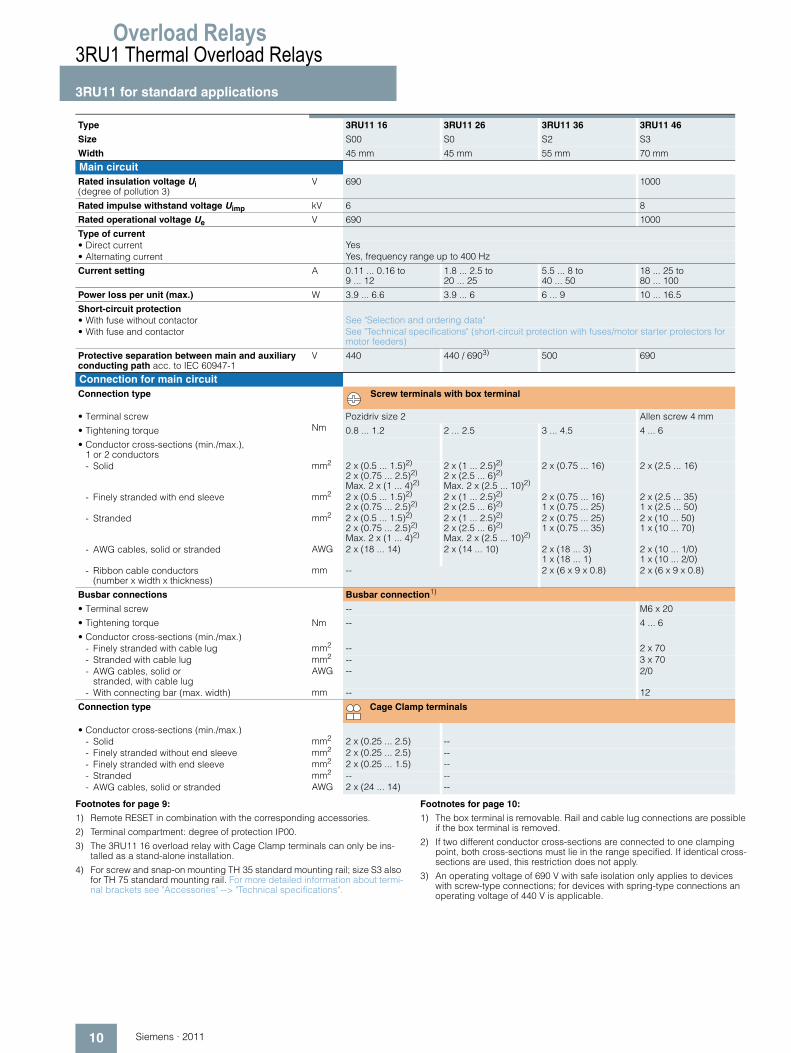
Type 3RU11 16 3RU11 26 3RU11 36 3RU11 46
Size S00 S0 S2 S3
Width 45 mm 45 mm 55 mm 70 mm
General dataTrips in the event of Overload and phase failure
Trip class acc. to IEC 60947-4-1 CLASS 10
Phase failure sensitivity Yes
Overload warning No
Reset and recovery• Reset options after tripping Manual, automatic and remote RESET1)
• Recovery time- For automatic RESET min Depends on the strength of the tripping current and characteristic- For manual RESET min Depends on the strength of the tripping current and characteristic- For remote RESET min Depends on the strength of the tripping current and characteristic
Features• Display of operating state on device Yes, by means of TEST function/switch position indicator slide• TEST function Yes• RESET button Yes• STOP button Yes
Safe operation of motors with "increased safety" type of protectionEC type test certificate number acc. to directive 94/9/EC
DMT 98 ATEX G 001 II (2) GD, DMT 98 ATEX G 001 N1
Ambient temperature• Storage/transport °C -55 ... +80• Operation °C -20 ... +70• Temperature compensation °C Up to 60• Permissible rated current at
- Temperature inside control cabinet 60 °C % 100 (over +60 °C current reduction is not required)- Temperature inside control cabinet 70 °C % 87
Repeat terminals• Coil repeat terminal Yes Not required• Auxiliary contact repeat terminal Yes Not required
Degree of protection acc. to IEC 60529 IP20 IP202)
Touch protection acc. to IEC 61140 Finger-safe
Shock resistance with sine acc. to IEC 60068-2-27 g/ms 8/10
Electromagnetic compatibility (EMC) – Interference immunity• Conductor-related interference
- Burst acc. to IEC 61000-4-4 (corresponds to degree of severity 3)
kV EMC interference immunity is not relevant for thermal overload relays
- Surge acc. to IEC 61000-4-5 (corresponds to degree of severity 3)
kV EMC interference immunity is not relevant for thermal overload relays
• Electrostatic discharge acc. to IEC 61000-4-2 (corresponds to degree of severity 3)
kV EMC interference immunity is not relevant for thermal overload relays
• Field-related interference acc. to IEC 61000-4-3 (corresponds to degree of severity 3)
V/m EMC interference immunity is not relevant for thermal overload relays
Electromagnetic compatibility (EMC) – Emitted interference EMC interference immunity is not relevant for thermal overload relays
Resistance to extreme climates – Air humidity % 100
Dimensions See dimensional drawings
Installation altitude above sea level m Up to 2000; above this, please enquire
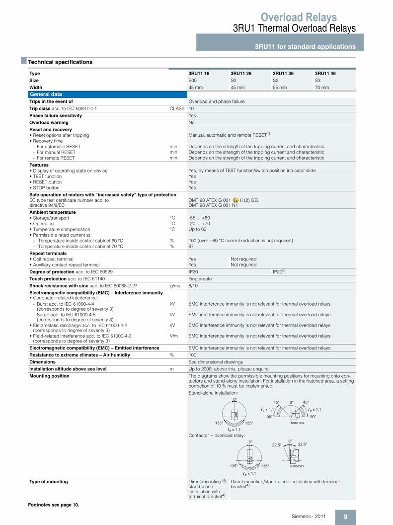
Mounting position The diagrams show the permissible mounting positions for mounting onto con-tactors and stand-alone installation. For installation in the hatched area, a setting correction of 10 % must be implemented.
Stand-alone installation:
Contactor + overload relay:
Type of mounting Direct mounting3)/ stand-alone installation withterminal bracket4)
Direct mounting/stand-alone installation with terminal bracket4)
� � � � � � � � � �
� � �
� � �
�
� � � � � �
� � � � � �
� �
� � � � � � � � � � � �
� � � � � � � �� � �
� �� � � � � � � �
� � �
� �
� �
� � � �
Overload Relays3RU1 Thermal Overload Relays3RU11 for standard applications
10 Siemens · 2011
Footnotes for page 9:
1) Remote RESET in combination with the corresponding accessories.
2) Terminal compartment: degree of protection IP00.
3) The 3RU11 16 overload relay with Cage Clamp terminals can only be ins-talled as a stand-alone installation.
4) For screw and snap-on mounting TH 35 standard mounting rail; size S3 also for TH 75 standard mounting rail. For more detailed information about termi-nal brackets see "Accessories" --> "Technical specifications".
Footnotes for page 10:
1) The box terminal is removable. Rail and cable lug connections are possible if the box terminal is removed.
2) If two different conductor cross-sections are connected to one clamping point, both cross-sections must lie in the range specified. If identical cross-sections are used, this restriction does not apply.
3) An operating voltage of 690 V with safe isolation only applies to devices with screw-type connections; for devices with spring-type connections an operating voltage of 440 V is applicable.
Type 3RU11 16 3RU11 26 3RU11 36 3RU11 46
Size S00 S0 S2 S3
Width 45 mm 45 mm 55 mm 70 mm
Main circuitRated insulation voltage Ui (degree of pollution 3)
V 690 1000
Rated impulse withstand voltage Uimp kV 6 8
Rated operational voltage Ue V 690 1000
Type of current• Direct current Yes• Alternating current Yes, frequency range up to 400 Hz
Current setting A 0.11 ... 0.16 to 9 ... 12
1.8 ... 2.5 to 20 ... 25
5.5 ... 8 to 40 ... 50
18 ... 25 to 80 ... 100
Power loss per unit (max.) W 3.9 ... 6.6 3.9 ... 6 6 ... 9 10 ... 16.5
Short-circuit protection• With fuse without contactor See "Selection and ordering data"• With fuse and contactor See "Technical specifications" (short-circuit protection with fuses/motor starter protectors for
motor feeders)
Protective separation between main and auxiliary conducting path acc. to IEC 60947-1
V 440 440 / 6903) 500 690
Connection for main circuitConnection type Screw terminals with box terminal
• Terminal screw Pozidriv size 2 Allen screw 4 mm
• Tightening torque Nm 0.8 ... 1.2 2 ... 2.5 3 ... 4.5 4 ... 6
• Conductor cross-sections (min./max.), 1 or 2 conductors- Solid mm2 2 x (0.5 ... 1.5)2)
2 x (0.75 ... 2.5)2) Max. 2 x (1 ... 4)2)
2 x (1 ... 2.5)2) 2 x (2.5 ... 6)2) Max. 2 x (2.5 ... 10)2)
2 x (0.75 ... 16) 2 x (2.5 ... 16)
- Finely stranded with end sleeve mm2 2 x (0.5 ... 1.5)2) 2 x (0.75 ... 2.5)2)
2 x (1 ... 2.5)2) 2 x (2.5 ... 6)2)
2 x (0.75 ... 16) 1 x (0.75 ... 25)
2 x (2.5 ... 35) 1 x (2.5 ... 50)
- Stranded mm2 2 x (0.5 ... 1.5)2) 2 x (0.75 ... 2.5)2) Max. 2 x (1 ... 4)2)
2 x (1 ... 2.5)2) 2 x (2.5 ... 6)2) Max. 2 x (2.5 ... 10)2)
2 x (0.75 ... 25) 1 x (0.75 ... 35)
2 x (10 ... 50) 1 x (10 ... 70)
- AWG cables, solid or stranded AWG 2 x (18 ... 14) 2 x (14 ... 10) 2 x (18 ... 3) 1 x (18 ... 1)
2 x (10 ... 1/0) 1 x (10 ... 2/0)
- Ribbon cable conductors (number x width x thickness)
mm -- 2 x (6 x 9 x 0.8) 2 x (6 x 9 x 0.8)
Busbar connections Busbar connection1)
• Terminal screw -- M6 x 20
• Tightening torque Nm -- 4 ... 6
• Conductor cross-sections (min./max.)- Finely stranded with cable lug mm2 -- 2 x 70- Stranded with cable lug mm2 -- 3 x 70- AWG cables, solid or
stranded, with cable lugAWG -- 2/0
- With connecting bar (max. width) mm -- 12
Connection type Cage Clamp terminals
• Conductor cross-sections (min./max.)- Solid mm2 2 x (0.25 ... 2.5) --- Finely stranded without end sleeve mm2 2 x (0.25 ... 2.5) --- Finely stranded with end sleeve mm2 2 x (0.25 ... 1.5) --- Stranded mm2 -- --- AWG cables, solid or stranded AWG 2 x (24 ... 14) --
Overload Relays
11Siemens · 2011
3RU1 Thermal Overload Relays
3RU11 for standard applications
1) On request.
2) Up to Ik ≤ 0.5 kA; ≤ 260 V.
3) If two different conductor cross-sections are connected to one clamping point, both cross-sections must lie in the range specified. If identical cross-sections are used, this restriction does not apply.
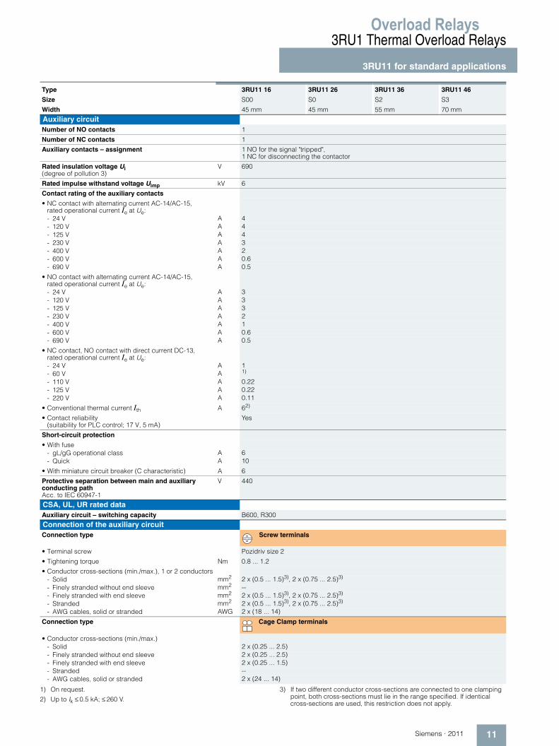
Type 3RU11 16 3RU11 26 3RU11 36 3RU11 46
Size S00 S0 S2 S3
Width 45 mm 45 mm 55 mm 70 mm
Auxiliary circuitNumber of NO contacts 1
Number of NC contacts 1
Auxiliary contacts – assignment 1 NO for the signal "tripped", 1 NC for disconnecting the contactor
Rated insulation voltage Ui (degree of pollution 3)
V 690
Rated impulse withstand voltage Uimp kV 6
Contact rating of the auxiliary contacts
• NC contact with alternating current AC-14/AC-15, rated operational current Ie at Ue:- 24 V A 4- 120 V A 4- 125 V A 4- 230 V A 3- 400 V A 2- 600 V A 0.6- 690 V A 0.5
• NO contact with alternating current AC-14/AC-15, rated operational current Ie at Ue:- 24 V A 3- 120 V A 3- 125 V A 3- 230 V A 2- 400 V A 1- 600 V A 0.6- 690 V A 0.5
• NC contact, NO contact with direct current DC-13, rated operational current Ie at Ue:- 24 V A 1- 60 V A 1)
- 110 V A 0.22- 125 V A 0.22- 220 V A 0.11
• Conventional thermal current Ith A 62)
• Contact reliability (suitability for PLC control; 17 V, 5 mA)
Yes
Short-circuit protection
• With fuse- gL/gG operational class A 6- Quick A 10
• With miniature circuit breaker (C characteristic) A 6
Protective separation between main and auxiliary conducting path Acc. to IEC 60947-1
V 440
CSA, UL, UR rated dataAuxiliary circuit – switching capacity B600, R300
Connection of the auxiliary circuitConnection type Screw terminals
• Terminal screw Pozidriv size 2
• Tightening torque Nm 0.8 ... 1.2
• Conductor cross-sections (min./max.), 1 or 2 conductors- Solid mm2 2 x (0.5 ... 1.5)3), 2 x (0.75 ... 2.5)3)
- Finely stranded without end sleeve mm2 --- Finely stranded with end sleeve mm2 2 x (0.5 ... 1.5)3), 2 x (0.75 ... 2.5)3)
- Stranded mm2 2 x (0.5 ... 1.5)3), 2 x (0.75 ... 2.5)3)
- AWG cables, solid or stranded AWG 2 x (18 ... 14)
Connection type Cage Clamp terminals
• Conductor cross-sections (min./max.)- Solid 2 x (0.25 ... 2.5)- Finely stranded without end sleeve 2 x (0.25 ... 2.5)- Finely stranded with end sleeve 2 x (0.25 ... 1.5)- Stranded --- AWG cables, solid or stranded 2 x (24 ... 14)
Overload Relays3RU1 Thermal Overload Relays3RU11 for standard applications
12 Siemens · 2011
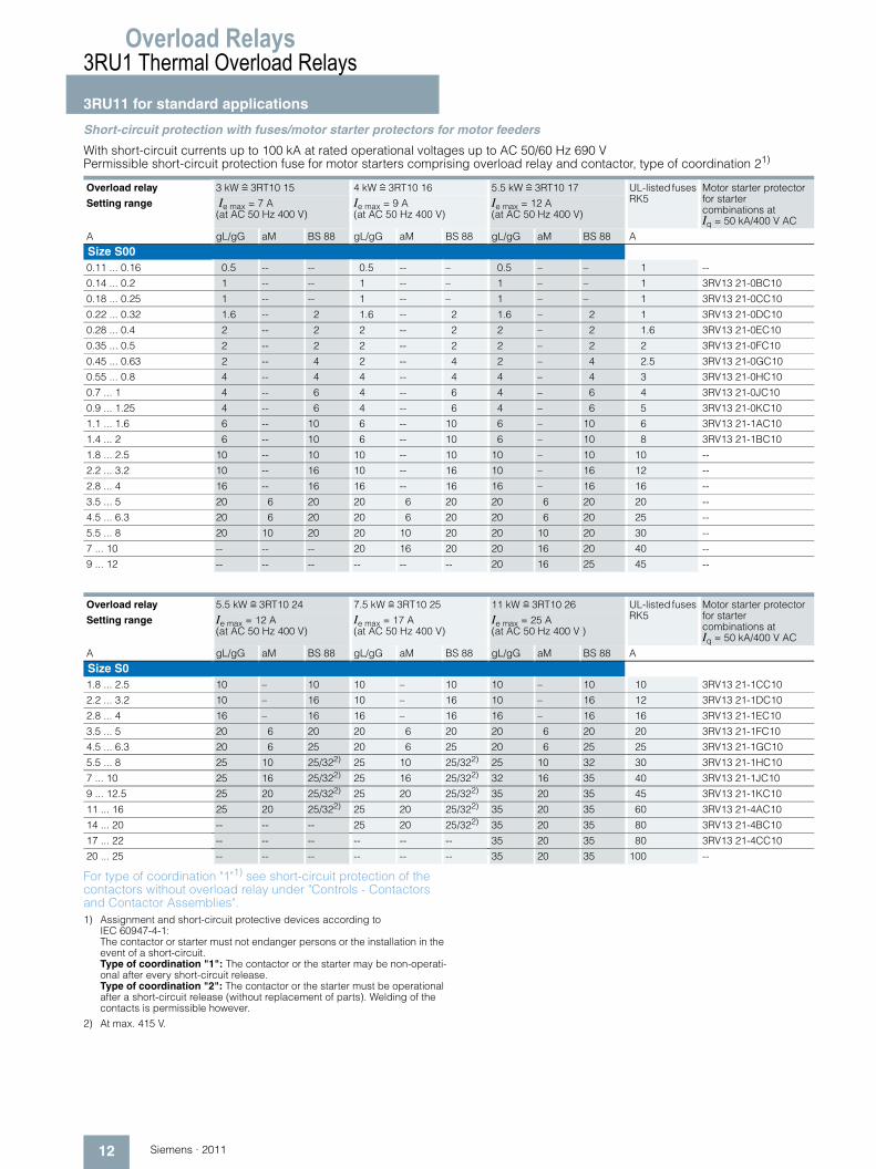
Short-circuit protection with fuses/motor starter protectors for motor feeders
With short-circuit currents up to 100 kA at rated operational voltages up to AC 50/60 Hz 690 V Permissible short-circuit protection fuse for motor starters comprising overload relay and contactor, type of coordination 21)
For type of coordination "1"1) see short-circuit protection of the contactors without overload relay under "Controls - Contactors and Contactor Assemblies".1) Assignment and short-circuit protective devices according to
IEC 60947-4-1: The contactor or starter must not endanger persons or the installation in the event of a short-circuit. Type of coordination "1": The contactor or the starter may be non-operati-onal after every short-circuit release. Type of coordination "2": The contactor or the starter must be operational after a short-circuit release (without replacement of parts). Welding of the contacts is permissible however.
2) At max. 415 V.
Overload relay 3 kW r 3RT10 15 4 kW r 3RT10 16 5.5 kW r 3RT10 17 UL-listed fuses RK5
Motor starter protector for starter combinations at Iq = 50 kA/400 V AC
Setting range Ie max = 7 A (at AC 50 Hz 400 V)
Ie max = 9 A (at AC 50 Hz 400 V)
Ie max = 12 A (at AC 50 Hz 400 V)
A gL/gG aM BS 88 gL/gG aM BS 88 gL/gG aM BS 88 A
Size S00 0.11 ... 0.16 0.5 -- -- 0.5 -- – 0.5 – – 1 --
0.14 ... 0.2 1 -- -- 1 -- – 1 – – 1 3RV13 21-0BC10
0.18 ... 0.25 1 -- -- 1 -- – 1 – – 1 3RV13 21-0CC10
0.22 ... 0.32 1.6 -- 2 1.6 -- 2 1.6 – 2 1 3RV13 21-0DC10
0.28 ... 0.4 2 -- 2 2 -- 2 2 – 2 1.6 3RV13 21-0EC10
0.35 ... 0.5 2 -- 2 2 -- 2 2 – 2 2 3RV13 21-0FC10
0.45 ... 0.63 2 -- 4 2 -- 4 2 – 4 2.5 3RV13 21-0GC10
0.55 ... 0.8 4 -- 4 4 -- 4 4 – 4 3 3RV13 21-0HC10
0.7 ... 1 4 -- 6 4 -- 6 4 – 6 4 3RV13 21-0JC10
0.9 ... 1.25 4 -- 6 4 -- 6 4 – 6 5 3RV13 21-0KC10
1.1 ... 1.6 6 -- 10 6 -- 10 6 – 10 6 3RV13 21-1AC10
1.4 ... 2 6 -- 10 6 -- 10 6 – 10 8 3RV13 21-1BC10
1.8 ... 2.5 10 -- 10 10 -- 10 10 – 10 10 --
2.2 ... 3.2 10 -- 16 10 -- 16 10 – 16 12 --
2.8 ... 4 16 -- 16 16 -- 16 16 – 16 16 --
3.5 ... 5 20 6 20 20 6 20 20 6 20 20 --
4.5 ... 6.3 20 6 20 20 6 20 20 6 20 25 --
5.5 ... 8 20 10 20 20 10 20 20 10 20 30 --
7 ... 10 -- -- -- 20 16 20 20 16 20 40 --
9 ... 12 -- -- -- -- -- -- 20 16 25 45 --
Overload relay 5.5 kW r 3RT10 24 7.5 kW r 3RT10 25 11 kW r 3RT10 26 UL-listed fuses RK5
Motor starter protector for starter combinations at Iq = 50 kA/400 V AC
Setting range Ie max = 12 A (at AC 50 Hz 400 V)
Ie max = 17 A (at AC 50 Hz 400 V)
Ie max = 25 A (at AC 50 Hz 400 V )
A gL/gG aM BS 88 gL/gG aM BS 88 gL/gG aM BS 88 A
Size S01.8 ... 2.5 10 – 10 10 – 10 10 – 10 10 3RV13 21-1CC10
2.2 ... 3.2 10 – 16 10 – 16 10 – 16 12 3RV13 21-1DC10
2.8 ... 4 16 – 16 16 – 16 16 – 16 16 3RV13 21-1EC10
3.5 ... 5 20 6 20 20 6 20 20 6 20 20 3RV13 21-1FC10
4.5 ... 6.3 20 6 25 20 6 25 20 6 25 25 3RV13 21-1GC10
5.5 ... 8 25 10 25/322) 25 10 25/322) 25 10 32 30 3RV13 21-1HC10
7 ... 10 25 16 25/322) 25 16 25/322) 32 16 35 40 3RV13 21-1JC10
9 ... 12.5 25 20 25/322) 25 20 25/322) 35 20 35 45 3RV13 21-1KC10
11 ... 16 25 20 25/322) 25 20 25/322) 35 20 35 60 3RV13 21-4AC10
14 ... 20 -- -- -- 25 20 25/322) 35 20 35 80 3RV13 21-4BC10
17 ... 22 -- -- -- -- -- -- 35 20 35 80 3RV13 21-4CC10
20 ... 25 -- -- -- -- -- -- 35 20 35 100 --
Overload Relays
13Siemens · 2011
3RU1 Thermal Overload Relays
3RU11 for standard applications
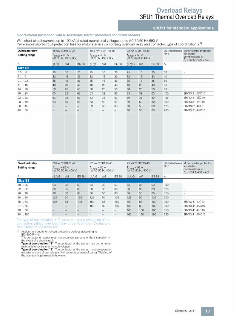
Short-circuit protection with fuses/motor starter protectors for motor feeders
With short-circuit currents up to 100 kA at rated operational voltages up to AC 50/60 Hz 690 V Permissible short-circuit protection fuse for motor starters comprising overload relay and contactor, type of coordination 21)
For type of coordination "1"1) see short-circuit protection of the contactors without overload relay under "Controls - Contactors and Contactor Assemblies".1) Assignment and short-circuit protective devices according to
IEC 60947-4-1: The contactor or starter must not endanger persons or the installation in the event of a short-circuit. Type of coordination "1": The contactor or the starter may be non-ope-rational after every short-circuit release. Type of coordination "2": The contactor or the starter must be operatio-nal after a short-circuit release (without replacement of parts). Welding of the contacts is permissible however.
Overload relay 15 kW r 3RT10 34 18.5 kW r 3RT10 35 22 kW r 3RT10 36 UL-listed fuses RK5
Motor starter protector for starter combinations at Iq = 50 kA/400 V AC
Setting range Ie max = 32 A (at AC 50 Hz 400 V)
Ie max = 40 A (at AC 50 Hz 400 V)
Ie max = 50 A (at AC 50 Hz 400 V)
A gL/gG aM BS 88 gL/gG aM BS 88 gL/gG aM BS 88 A
Size S25.5 ... 8 25 10 25 25 10 25 25 10 25 30 --
7 ... 10 32 16 32 32 16 32 32 16 32 40 --
9 ... 12.5 35 16 35 35 16 35 35 16 35 50 --
11 ... 16 40 20 40 40 20 40 40 20 40 60 --
14 ... 20 50 25 50 50 25 50 50 25 50 80 --
18 ... 25 63 32 63 63 32 63 63 32 63 100 3RV13 31-4DC10
22 ... 32 63 35 63 63 35 63 80 35 80 125 3RV13 31-4EC10
28 ... 40 63 50 63 63 50 63 80 50 80 150 3RV13 31-4FC10
36 ... 45 -- -- -- 63 50 80 80 50 80 175 3RV13 31-4GC10
40 ... 50 -- -- -- -- -- -- 80 50 80 200 3RV13 31-4HC10
Overload relay 30 kW r 3RT10 44 37 kW r 3RT10 45 45 kW r 3RT10 46 UL-listed fuses RK5
Motor starter protector for starter combinations at Iq = 50 kA/400 V AC
Setting range Ie max = 65 A (at AC 50 Hz 400 V)
Ie max = 80 A (at AC 50 Hz 400 V)
Ie max = 95 A (at AC 50 Hz 400 V)
A gL/gG aM BS 88 gL/gG aM BS 88 gL/gG aM BS 88 A
Size S318 ... 25 63 32 63 63 32 63 63 32 63 100 --
22 ... 32 80 35 80 80 35 80 80 35 80 125 --
28 ... 40 80 50 80 80 50 80 80 50 80 150 --
36 ... 50 125 50 125 125 50 125 125 50 125 200 --
45 ... 63 125 63 125 160 63 160 160 63 160 250 3RV13 41-4JC10
57 ... 75 -- -- -- 160 80 160 160 80 160 300 3RV13 41-4KC10
70 ... 90 -- -- -- -- -- -- 160 100 160 350 3RV13 41-4LC10
80 ... 100 -- -- -- -- -- -- 160 100 160 350 3RV13 41-4MC10
Overload Relays3RU1 Thermal Overload Relays3RU11 for standard applications
14 Siemens · 2011
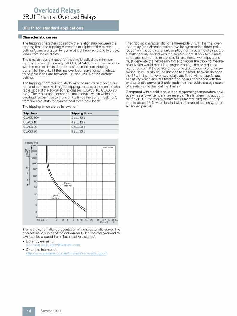
■ Characteristic curves
The tripping characteristics show the relationship between the tripping time and tripping current as multiples of the current setting Ie and are given for symmetrical three-pole and two-pole loads from the cold state.
The smallest current used for tripping is called the minimum tripping current. According to IEC 60947-4-1, this current must be within specified limits. The limits of the minimum tripping current for the 3RU11 thermal overload relays for symmetrical three-pole loads are between 105 and 120 % of the current setting.
The tripping characteristic starts with the minimum tripping cur-rent and continues with higher tripping currents based on the cha-racteristics of the so-called trip classes (CLASS 10, CLASS 20 etc.). The trip classes describe time intervals within which the overload relays have to trip with 7.2 times the current setting Ie from the cold state for symmetrical three-pole loads.
The tripping times are as follows for:
This is the schematic representation of a characteristic curve. The characteristic curves of the individual 3RU11 thermal overload re-lays can be ordered from "Technical Assistance":• Either by e-mail to:
[email protected]• Or on the Internet at:
http://www.siemens.com/automation/service&support
The tripping characteristic for a three-pole 3RU11 thermal over-load relay (see characteristic curve for symmetrical three-pole loads from the cold state) only applies if all three bimetal strips are simultaneously loaded with the same current. If only two bimetal strips are heated due to a phase failure, these two strips alone must generate the necessary force to trigger the tripping mecha-nism which would result in a longer tripping time or require a higher current. If these higher currents are applied over a longer period, they usually cause damage to the load. To avoid damage, the 3RU11 thermal overload relays are fitted with phase failure sensitivity which ensures faster tripping in accordance with the characteristic curve for 2-pole loads from the cold state by means of a suitable mechanical mechanism.
Compared with a cold load, a load at operating temperature obvi-ously has a lower temperature reserve. This is taken into account by the 3RU11 thermal overload relays by reducing the tripping time to about 25 % when loaded with the current setting Ie for an extended period.
Trip class Tripping times
CLASS 10A 2 s ... 10 s
CLASS 10 4 s ... 10 s
CLASS 20 6 s ... 20 s
CLASS 30 9 s ... 30 s
10
100
1000
10 000
5000
2000
500
200
50
20
5
2
1
1
2
5
10
4060
100
0,6 0,8 1 2 3 4 6 8 10 20 30 40 60 80 x � nA
s
15
NSB0_00288
Tripping time
3-poleloading
2-poleloading
Current
min
Overload Relays
15Siemens · 2011
3RU1 Thermal Overload Relays
3RU11 for standard applications
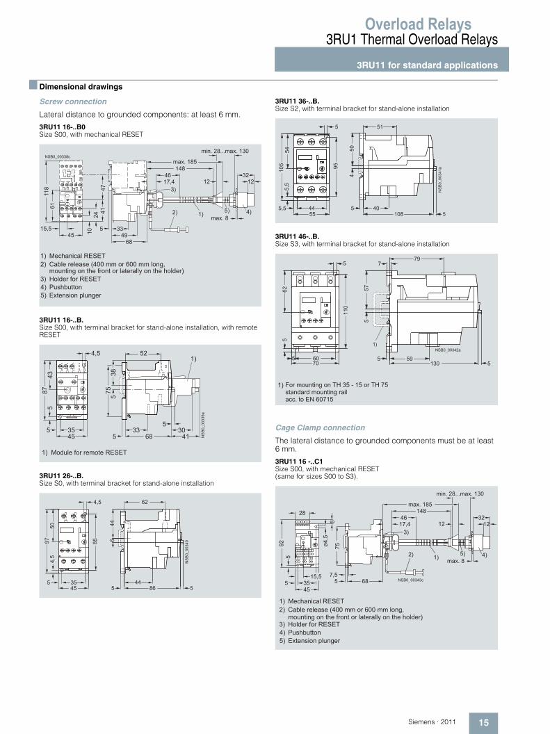
■ Dimensional drawings
Screw connection
Lateral distance to grounded components: at least 6 mm.
3RU11 16-..B0 Size S00, with mechanical RESET
3RU11 16-..B. Size S00, with terminal bracket for stand-alone installation, with remote RESET
3RU11 26-..B. Size S0, with terminal bracket for stand-alone installation
3RU11 36-..B. Size S2, with terminal bracket for stand-alone installation
3RU11 46-..B. Size S3, with terminal bracket for stand-alone installation
Cage Clamp connection
The lateral distance to grounded components must be at least 6 mm.
3RU11 16 -..C1 Size S00, with mechanical RESET(same for sizes S00 to S3).
15,5
6111
8
1024
4147
455 33
4968
max. 185148
17,446
min. 28...max. 130
1232
12
max. 82) 1)
3)
NSB0_00338c
4)5)
Cable release (400 mm or 600 mm long, mounting on the front or laterally on the holder)
2)Mechanical RESET1)
Holder for RESET3)Pushbutton4)Extension plunger5)
4,5 52
333545
55
538
758743
5
5
68 NS
B0_
0033
9a
41
1)
30
1) Module for remote RESET
��
���������
�
�
�
�
�
� �
� �
�
����������
�
�
��
�
�
�
� � �
�
� � � � � � � � � �
� �
� ��
� ��
� ��
�
� � � �
�
� �
�
� �
� � � � � � � � � � � � � � � � � � � � � � � � � � � � � � � � � �� � � � � � � � � � � � � � � � � � � � �� � � � � � � � � � � � � � �
45355
15,5
925
8Ø
4,5
75
57,5
68
28
2) 1)
3)
max. 8
min. 28...max. 130
12 123246
17,4
max. 185148
NSB0_00343c
4)5)
Cable release (400 mm or 600 mm long, mounting on the front or laterally on the holder)
2)Mechanical RESET1)
Holder for RESET3)Pushbutton4)Extension plunger5)
Overload Relays3RU1 Thermal Overload Relays3RU11 for standard applications
16 Siemens · 2011
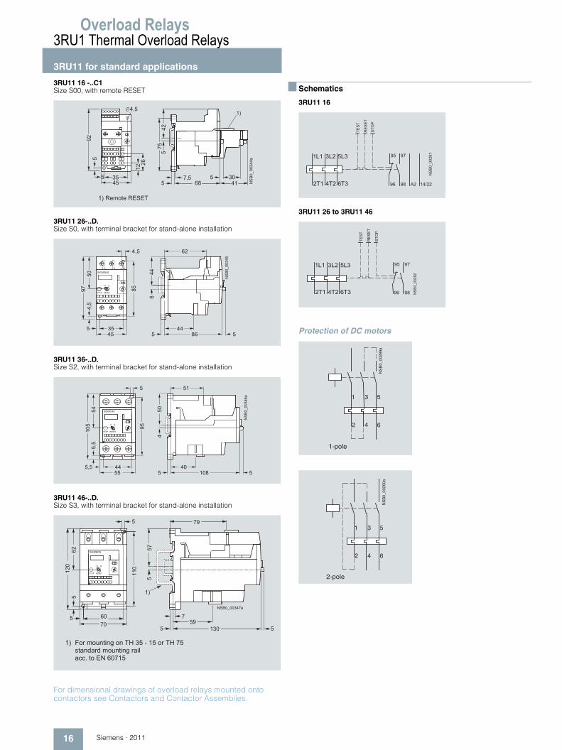
3RU11 16 -..C1 Size S00, with remote RESET
3RU11 26-..D. Size S0, with terminal bracket for stand-alone installation
3RU11 36-..D. Size S2, with terminal bracket for stand-alone installation
3RU11 46-..D. Size S3, with terminal bracket for stand-alone installation
For dimensional drawings of overload relays mounted onto contactors see Contactors and Contactor Assemblies.
■ Schematics
3RU11 16
3RU11 26 to 3RU11 46
Protection of DC motors
� �
� �
���
�
! �
� " ! �
� � ��
��
�
����
�#$�%
��
�
� � & ' � � � ' � & � # � �
� �
� � � � �� � � �
� � � �� �
�
��
�
�
�
�
� �
� � �
��������
� � � � � � �
�
��
�
�
�
� � � �
�
� �
� � � � �� � � �
� � � �� �
� � � � � � �
����������
���
���
� � � �
���
�
�
��
� �� �
�
�
� (
& � # � �# � ) *
� � # �� �
� � � � � � �
� � � � � � � � � �
� �
� � � � � � � � � � � � � � � � � � � � � � � � � � � � � � � � � �� � � � � � � � � � � � � � � � � � � � �� � � � � � � � � � � � � � �
�
� �
� �
� � � � � � � �
����������
� � � � �� � �
� � � � �
����
�����
����
�
� �
� �
� � ����������
� � � � �� � �
� � � � �
����
�����
����
NS
B0_
0028
9a
4 62
1 3 5
1-pole
NS
B0_
0029
0a
4 62
1 3 5
2-pole
Overload Relays
17Siemens · 2011
3RU1 Thermal Overload Relays
Accessories
■ Overview
The following accessories are available for the 3RU11 thermal overload relays:• For the four overload relay sizes S00 to S3 one terminal bra-
cket each for stand-alone installation• One electrical remote RESET module in three voltage variants
for all sizes
• One mechanical RESET module for all sizes• One cable release for resetting devices which are difficult to
access (for all sizes)• Terminal covers
■ Technical specifications
Terminal brackets for stand-alone installation
Type 3RU19 16-3AA01 3RU19 26-3AA01 3RU1 936-3AA01 3RU19 46-3AA01
For overload relays 3RU11 16 3RU11 26 3RU11 36 3RU11 46
Mounting type For screw and snap-on mounting onto TH 35 standard mounting rails, size S3 also for TH 75 standard mounting rails.
Connection for main circuitConnection type Screw terminals Screw terminals with
box terminal
• Terminal screw Pozidriv size 2 Allen screw 4 mm
• Conductor cross-section (min./max.), 1 or 2 conductors
- Solid mm2 1 x (0.5 ... 2.5), max. 1 x (... 4)
1 x (1 ... 6), max. 1 x (... 10)
2 x (0.75 ... 16) 2 x (2.5 ... 16)
- Finely stranded without end sleeve mm2 --
- Finely stranded with end sleeve mm2 1 x (0.5 ... 2.5) 1 x (1 ... 6) 2 x (0.75 ... 16), 1 x (0.75 ... 25)
2 x (2.5 ... 35), 1 x (2.5 ... 50)
- Stranded mm2 1 x (0.5 ... 2.5), max. 1 x (... 4)
1 x (1 ... 6), max. 1 x (... 10)
2 x (0.75 ... 25), 1 x (0.75 ... 35)
2 x (10 ... 50), 1 x (10 ... 70)
- AWG cables, solid or stranded AWG 1 x (18 ... 14) 1 x (14 ... 10) 2 x (18 ... 3), 1 x (18 ... 1)
2 x (10 ... 1/0), 1 x (10 ... 2/0)
- Ribbon cable conductors (number x width x thickness) mm -- -- 2 x (6 x 9 x 0.8) 2 x (6 x 9 x 0.8)
Overload Relays3RB2 Solid-State Overload Relays3RB20, 3RB21 for standard applications
18 Siemens · 2011
■ Overview
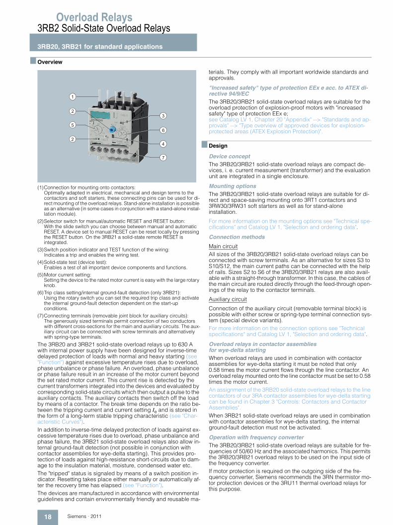
(1)Connection for mounting onto contactors: Optimally adapted in electrical, mechanical and design terms to the contactors and soft starters, these connecting pins can be used for di-rect mounting of the overload relays. Stand-alone installation is possible as an alternative (in some cases in conjunction with a stand-alone instal-lation module).
(2)Selector switch for manual/automatic RESET and RESET button: With the slide switch you can choose between manual and automatic RESET. A device set to manual RESET can be reset locally by pressing the RESET button. On the 3RB21 a solid-state remote RESET isintegrated.
(3)Switch position indicator and TEST function of the wiring: Indicates a trip and enables the wiring test.
(4)Solid-state test (device test): Enables a test of all important device components and functions.
(5)Motor current setting: Setting the device to the rated motor current is easy with the large rotary knob.
(6)Trip class setting/internal ground-fault detection (only 3RB21): Using the rotary switch you can set the required trip class and activate the internal ground-fault detection dependent on the start-upconditions.
(7)Connecting terminals (removable joint block for auxiliary circuits): The generously sized terminals permit connection of two conductors with different cross-sections for the main and auxiliary circuits. The aux-iliary circuit can be connected with screw terminals and alternatively with spring-type terminals.
The 3RB20 and 3RB21 solid-state overload relays up to 630 A with internal power supply have been designed for inverse-time delayed protection of loads with normal and heavy starting (see "Function") against excessive temperature rises due to overload, phase unbalance or phase failure. An overload, phase unbalance or phase failure result in an increase of the motor current beyond the set rated motor current. This current rise is detected by the current transformers integrated into the devices and evaluated by corresponding solid-state circuits which then output a pulse to the auxiliary contacts. The auxiliary contacts then switch off the load by means of a contactor. The break time depends on the ratio be-tween the tripping current and current setting Ie and is stored in the form of a long-term stable tripping characteristic (see "Char-acteristic Curves").In addition to inverse-time delayed protection of loads against ex-cessive temperature rises due to overload, phase unbalance and phase failure, the 3RB21 solid-state overload relays also allow in-ternal ground-fault detection (not possible in conjunction with contactor assemblies for wye-delta starting). This provides pro-tection of loads against high-resistance short-circuits due to dam-age to the insulation material, moisture, condensed water etc.The "tripped" status is signaled by means of a switch position in-dicator. Resetting takes place either manually or automatically af-ter the recovery time has elapsed (see "Function").The devices are manufactured in accordance with environmental guidelines and contain environmentally friendly and reusable ma-
terials. They comply with all important worldwide standards and approvals.
"Increased safety" type of protection EEx e acc. to ATEX di-rective 94/9/ECThe 3RB20/3RB21 solid-state overload relays are suitable for the overload protection of explosion-proof motors with "increased safety" type of protection EEx e; see Catalog LV 1, Chapter 20 "Appendix" --> "Standards and ap-provals" --> "Type overview of approved devices for explosion-protected areas (ATEX Explosion Protection)".
■ Design
Device conceptThe 3RB20/3RB21 solid-state overload relays are compact de-vices, i. e. current measurement (transformer) and the evaluation unit are integrated in a single enclosure.
Mounting optionsThe 3RB20/3RB21 solid-state overload relays are suitable for di-rect and space-saving mounting onto 3RT1 contactors and 3RW30/3RW31 soft starters as well as for stand-aloneinstallation.
For more information on the mounting options see "Technical spe-cifications" and Catalog LV 1, "Selection and ordering data".
Connection methods
Main circuitAll sizes of the 3RB20/3RB21 solid-state overload relays can be connected with screw terminals. As an alternative for sizes S3 to S10/S12, the main current paths can be connected with the help of rails. Sizes S2 to S6 of the 3RB20/3RB21 relays are also avail-able with a straight-through transformer. In this case, the cables of the main circuit are routed directly through the feed-through open-ings of the relay to the contactor terminals.
Auxiliary circuit
Connection of the auxiliary circuit (removable terminal block) is possible with either screw or spring-type terminal connection sys-tem (special device variants).For more information on the connection options see "Technical specifications" and Catalog LV 1, "Selection and ordering data".
Overload relays in contactor assemblies for wye-delta startingWhen overload relays are used in combination with contactor assemblies for wye-delta starting it must be noted that only 0.58 times the motor current flows through the line contactor. An overload relay mounted onto the line contactor must be set to 0.58 times the motor current.An assignment of the 3RB20 solid-state overload relays to the line contactors of our 3RA contactor assemblies for wye-delta starting can be found in Chapter 3 "Controls: Contactors and Contactor Assemblies".When 3RB21 solid-state overload relays are used in combination with contactor assemblies for wye-delta starting, the internal ground-fault detection must not be activated.
Operation with frequency converterThe 3RB20/3RB21 solid-state overload relays are suitable for fre-quencies of 50/60 Hz and the associated harmonics. This permits the 3RB20/3RB21 overload relays to be used on the input side of the frequency converter.If motor protection is required on the outgoing side of the fre-quency converter, Siemens recommends the 3RN thermistor mo-tor protection devices or the 3RU11 thermal overload relays for this purpose.
1
2
5
2
3
6
4
7
Overload Relays
19Siemens · 2011
3RB2 Solid-State Overload Relays
3RB20, 3RB21 for standard applications
■ Function
Basic functions
The 3RB20/3RB21 solid-state overload relays are designed for:• Inverse-time delayed protection of loads from overloading• Inverse-time delayed protection of loads from phase
unbalance• Inverse-time delayed protection of loads from phase failure• Protection of loads from high-resistance short-circuits (internal
ground-fault detection only with 3RB21).
Control circuit
The 3RB20/3RB21 solid-state overload relays have an internal power supply, i. e. no additional supply voltage is required.
Short-circuit protection
Fuses or motor starter protectors must be used for short-circuit protection.
For assignments of the corresponding short-circuit protection devices to the 3RB20/3RB21 solid-state overload relays with/wi-thout contactor see "Technical specifications" and Catalog LV 1, "Selection and ordering data".
Trip classes
The 3RB20 solid-state overload relays are available for normal starting conditions with trip CLASS 10 or for heavy starting con-ditions with trip CLASS 20 (fixed setting in each case).The 3RB21 solid-state overload relays are suitable for normal and heavy starting conditions. The required trip class (CLASS 5, 10, 20 or 30) can be adjusted by means of a rotary switch de-pending on the current start-up condition.For details of the trip classes see "Characteristic Curves".
Phase failure protection
The 3RB20/3RB21 solid-state overload relays are fitted with phase failure protection (see "Characteristic Curves") in order to minimize temperature rises of the load during single-phase ope-ration.Phase failure protection is not effective for loads with star-con-nection and a grounded neutral point or a neutral point which is connected to a neutral conductor.
Setting
The 3RB20/3RB21 solid-state overload relays are set to the rated motor current by means of a rotary knob. The scale of the rotary knob is shown in ampere.With the 3RB21 solid-state overload relay it is also possible to se-lect the trip class (CLASS 5, 10, 20 or 30) using a second rotary knob and to switch the internal ground-fault detection on and off.
Manual and automatic reset
In the case of the 3RB20/3RB21 solid-state overload relays, a slide switch can be used to choose between automatic and ma-nual resetting.If manual reset is set, a reset can be carried out directly on the device after a trip by pressing the blue RESET button. Resetting is possible in combination with mechanical and mechanical re-set options from the range of accessories (see Catalog LV 1, "Accessories"). As an alternative to the mechanical RESET op-tions, the 3RB21 solid-state overload relays can be equipped with electrical remote RESET by applying a voltage of 24 V DC to the terminals A3 and A4.
If the slide switch is set to automatic RESET, the relay is reset automatically.
The time between tripping and resetting is determined by the recovery time.
Recovery time
With the 3RB20/3RB21 solid-state overload relays the recovery time after inverse-time delayed tripping is 3 minutes when auto-matic RESET is set. This recovery time allows the load to cool down.
If the button is set to manual RESET and automatic RESET, the 3RB20/3RB21 devices can be reset immediately after tripping.
TEST function
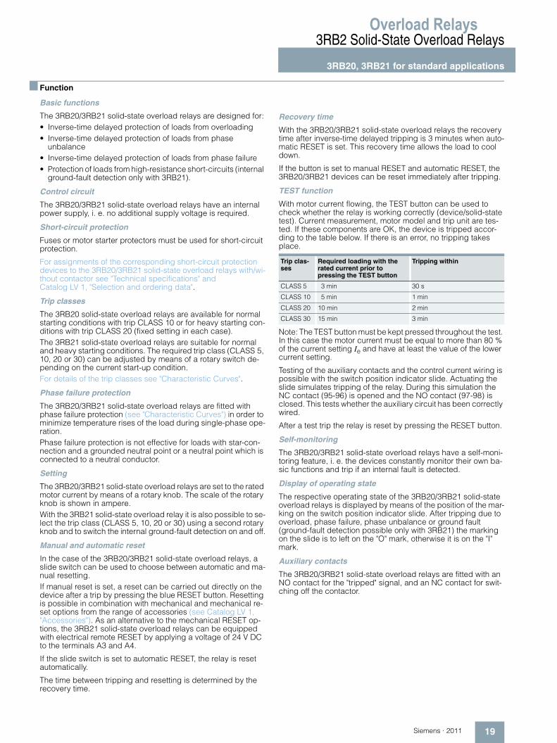
With motor current flowing, the TEST button can be used to check whether the relay is working correctly (device/solid-state test). Current measurement, motor model and trip unit are tes-ted. If these components are OK, the device is tripped accor-ding to the table below. If there is an error, no tripping takes place.
Note: The TEST button must be kept pressed throughout the test. In this case the motor current must be equal to more than 80 % of the current setting Ie and have at least the value of the lower current setting.
Testing of the auxiliary contacts and the control current wiring is possible with the switch position indicator slide. Actuating the slide simulates tripping of the relay. During this simulation the NC contact (95-96) is opened and the NO contact (97-98) is closed. This tests whether the auxiliary circuit has been correctly wired.
After a test trip the relay is reset by pressing the RESET button.
Self-monitoring
The 3RB20/3RB21 solid-state overload relays have a self-moni-toring feature, i. e. the devices constantly monitor their own ba-sic functions and trip if an internal fault is detected.
Display of operating state
The respective operating state of the 3RB20/3RB21 solid-state overload relays is displayed by means of the position of the mar-king on the switch position indicator slide. After tripping due to overload, phase failure, phase unbalance or ground fault (ground-fault detection possible only with 3RB21) the marking on the slide is to left on the "O" mark, otherwise it is on the "I" mark.
Auxiliary contacts
The 3RB20/3RB21 solid-state overload relays are fitted with an NO contact for the "tripped" signal, and an NC contact for swit-ching off the contactor.
Trip clas-ses
Required loading with the rated current prior to pressing the TEST button
Tripping within
CLASS 5 3 min 30 s
CLASS 10 5 min 1 min
CLASS 20 10 min 2 min
CLASS 30 15 min 3 min
Overload Relays3RB2 Solid-State Overload Relays3RB20, 3RB21 for standard applications
20 Siemens · 2011
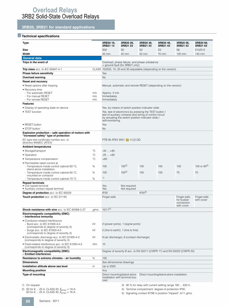
■ Technical specifications
1) On request.
2) S0 for 6 ... 25 A, CLASS 20, Iemax = 19 A; S0 for 6 ... 25 A, CLASS 30, Iemax = 16 A.
3) 90 % for relay with current setting range 160 ... 630 A.
4) Terminal compartment: degree of protection IP00.
5) Signaling contact 97/98 in position "tripped": 4/11 g/ms.
Type 3RB20 16, 3RB21 13
3RB20 26, 3RB21 23
3RB20 36, 3RB21 33
3RB20 46, 3RB21 43
3RB20 56, 3RB21 53
3RB20 66, 3RB21 63
Size S00 S0 S2 S3 S6 S10/S12
Width 45 mm 45 mm 55 mm 70 mm 120 mm 145 mm
General dataTrips in the event of Overload, phase failure, and phase unbalance
+ ground fault (for 3RB21 only)
Trip class acc. to IEC 60947-4-1 CLASS 10/20/5, 10, 20 and 30 adjustable (depending on the version)
Phase failure sensitivity Yes
Overload warning No
Reset and recovery
• Reset options after tripping Manual, automatic and remote RESET (depending on the version)
• Recovery time- For automatic RESET min. Approx. 3 min- For manual RESET min. Immediately- For remote RESET min. Immediately
Features
• Display of operating state on device Yes, by means of switch position indicator slide
• TEST function Yes, test of electronics by pressing the TEST button / test of auxiliary contacts and wiring of control circuit by actuating the switch position indicator slide / self-monitoring
• RESET button Yes
• STOP button No
Explosion protection – safe operation of motors with "increased safety" type of protection
EC type test certificate number acc. to directive 94/9/EC (ATEX)
PTB 06 ATEX 3001 II (2) GD
Ambient temperatures
• Storage/transport °C -40 ... +80
• Operation °C -25 ... +60
• Temperature compensation °C +60
• Permissible rated current at- Temperature inside control cabinet 60 °C,
stand-alone installation% 100 1002) 100 100 100 100 or 903)
- Temperature inside control cabinet 60 °C, mounted on contactor
% 100 1002) 100 100 70 70
- Temperature inside control cabinet 70 °C % 1)
Repeat terminals • Coil repeat terminal Yes Not required• Auxiliary contact repeat terminal Yes Not required
Degree of protection acc. to IEC 60529 IP20 IP204)
Touch protection acc. to IEC 61140 Finger-safe Finger-safe, for busbar connection with cover
Finger-safe with cover
Shock resistance with sine acc. to IEC 60068-2-27 g/ms 15/115)
Electromagnetic compatibility (EMC) – Interference immunity
• Conductor-related interference- Burst acc. to IEC 61000-4-4
(corresponds to degree of severity 3)kV 2 (power ports), 1 (signal ports)
- Surge acc. to IEC 61000-4-5 (corresponds to degree of severity 3)
kV 2 (line to earth), 1 (line to line)
• Electrostatic discharge acc. to IEC 61000-4-2 (corresponds to degree of severity 3)
kV 8 (air discharge), 6 (contact discharge)
• Field-related interference acc. to IEC 61000-4-3 (corresponds to degree of severity 3)
V/m 10
Electromagnetic compatibility (EMC) – Emitted interference
Degree of severity B acc. to EN 55011 (CISPR 11) and EN 55022 (CISPR 22)
Resistance to extreme climates – air humidity % 100
Dimensions See dimensional drawings
Installation altitude above sea level m Up to 2000
Mounting position Any
Type of mounting Direct mounting/stand-alone installation with terminal bra-cket
Direct mounting/stand-alone installation
Overload Relays
21Siemens · 2011
3RB2 Solid-State Overload Relays
3RB20, 3RB21 for standard applications
1) For version with straight-through transformer up to 1000 V AC.
2) For version with straight-through transformer up to 8 kV.
3) For grounded networks, otherwise 600 V.
4) If two different conductor cross-sections are connected to one clamping point, both cross-sections must lie in the range specified. If identical cross-sections are used, this restriction does not apply.
Type 3RB20 16, 3RB21 13
3RB20 26, 3RB21 23
3RB20 36, 3RB21 33
3RB20 46, 3RB21 43
Size S00 S0 S2 S3Width 45 mm 45 mm 55 mm 70 mm
Main circuitRated insulation voltage Ui (degree of pollution 3)
V 690 690/10001) 1000
Rated impulse withstand voltage Uimp kV 6 6/82) 8
Rated operational voltage Ue V 690 690/10001) 1000
Type of current• Direct current No• Alternating current Yes, 50/60 Hz ±5 %
Current setting A 0.1 ... 0.4 to 3 ... 12
0.1 ... 0.4 to 6 ... 25
6 ... 25 and 12.5 ... 50
12.5 ... 50 and 25 ... 100
Power loss per unit (max.) W 0.05
Short-circuit protection• With fuse without contactor See Catalog LV 1, "Selection and ordering data"• With fuse and contactor See "Technical specifications" (short-circuit protection with fuses for motor feeders)
Protective separation between main and auxiliary con-ducting path acc. to IEC 60947-1 (degree of pollution 2)
V 6903)
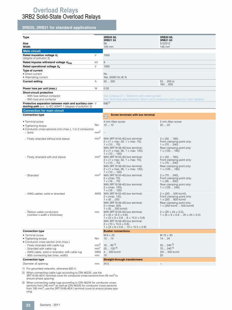
Connection for main circuitConnection type Screw terminals with box terminal
• Terminal screw Pozidriv size 2 Allen screw 4 mm• Tightening torque Nm 0.8 ... 1.2 2 ... 2.5 3 ... 4.5 4 ... 6• Conductor cross-sections (min./max.), 1 or 2 conductors
- Solid mm2 2 × (0.5 ... 1.5)4), 2 × (0.75 ... 2.5)4)
2 × (1 ... 2.5)4), 2 × (2.5 ... 6)4)
2 × (1 ... 16) 2 × (2.5 ... 16)
- Finely stranded without end sleeve mm2 --
- Finely stranded with end sleeve mm2 2 × (0.5 ... 1.5)4), 2 × (0.75 ... 2.5)4)
2 × (1 ... 2.5)4), 2 × (2.5 ... 6)4)
2 × (1 ... 16)4), 1 × ( 1 ... 25)4)
2 × (2.5 ... 35), 1 × (2.5 ... 50)
- Stranded mm2 -- 2 × (max. 25), 1 × (1 ... 35)
2 × (10 ... 50),1 × (10 ... 70)
- AWG cables, solid or stranded AWG 2 × (18 ... 14) 2 × (14 ... 10) 2 × (max. 4), 1 × (18 ... 2)
2 × (10 ... 1/0), 1 × (10 ... 2/0)
- Ribbon cable conductors (number x width x thickness)
mm -- 2 × (6 × 9 × 0.8) 2 × (6 × 9 × 0.8)
Connection type Busbar connections
• Terminal screw -- M 6 × 20• Tightening torque Nm -- 4 ... 6• Conductor cross-section (min./max.)
- Finely stranded with cable lug mm2 -- 2 × 70- Stranded with cable lug mm2 -- 3 × 70- AWG cable, solid or stranded, with cable lug AWG -- 2/0- With connecting bar (max. width) mm -- 12
Connection type Straight-through transformers
Diameter of opening mm -- 15 18
Overload Relays3RB2 Solid-State Overload Relays3RB20, 3RB21 for standard applications
22 Siemens · 2011
1) For grounded networks, otherwise 600 V.
2) When connecting cable lugs according to DIN 46235, use the 3RT19 56-4EA1 terminal cover for conductor cross-sections from 95 mm2 to ensure phase spacing.
3) When connecting cable lugs according to DIN 46234 for conductor cross-sections from 240 mm2 as well as DIN 46235 for conductor cross-sections from 185 mm2, use the 3RT19 66-4EA1 terminal cover to ensure phase spa-cing.
Type 3RB20 56, 3RB21 53
3RB20 66, 3RB21 63
Size S6 S10/S12Width 120 mm 145 mm
Main circuitRated insulation voltage Ui (degree of pollution 3)
V 1000
Rated impulse withstand voltage Uimp kV 8
Rated operational voltage Ue V 1000
Type of current• Direct current No• Alternating current Yes, 50/60 Hz ±5 %
Current setting A 50 ... 200 55 ... 250 to 160 ... 630
Power loss per unit (max.) W 0.05
Short-circuit protection- With fuse without contactor See Catalog LV 1, "Selection and ordering data"- With fuse and contactor See "Technical specifications" (short-circuit protection with fuses for motor feeders)
Protective separation between main and auxiliary con-ducting path acc. to IEC 60947-1 (degree of pollution 2)
V 6901)
Connection for main circuitConnection type Screw terminals with box terminal
• Terminal screw 4 mm Allen screw 5 mm Allen screw
• Tightening torque Nm 10 ... 12 20 ... 22
• Conductor cross-sections (min./max.), 1 or 2 conductors- Solid mm2 --
- Finely stranded without end sleeve mm2 With 3RT19 55-4G box terminal: 2 × (1 × max. 50, 1 × max. 70), 1 × (10 ... 70)With 3RT19 56-4G box terminal: 2 × (1 × max. 95, 1 × max. 120), 1 × (10 ... 120)
2 × (50 ... 185), Front clamping point only: 1 × (70 ... 240)Rear clamping point only: 1 × (120 ... 185)
- Finely stranded with end sleeve mm2 With 3RT19 55-4G box terminal: 2 × (1 × max. 50, 1 × max. 70), 1 × (10 ... 70)With 3RT19 56-4G box terminal: 2 × (1 × max. 95, 1 × max. 120), 1 × (10 ... 120)
2 × (50 ... 185), Front clamping point only: 1 × (70 ... 240)Rear clamping point only: 1 × (120 ... 185)
- Stranded mm2 With 3RT19 55-4G box terminal: 2 × (max. 70), 1 × (16 ... 70)With 3RT19 56-4G box terminal: 2 × (max. 120), 1 × (16 ... 120)
2 × (70 ... 240), Front clamping point only: 1 × (95 ... 300)Rear clamping point only: 1 × (120 ... 240)
- AWG cables, solid or stranded AWG With 3RT19 55-4G box terminal: 2 × (max. 1/0), 1 × (6 ... 2/0)With 3RT19 56-4G box terminal: 2 × (max. 3/0), 1 × (6 ... 250 kcmil)
2 × (2/0 ... 500 kcmil), Front clamping point only: 1 × (3/0 ... 600 kcmil)Rear clamping point only: 1 × (250 kcmil ... 500 kcmil)
- Ribbon cable conductors (number x width x thickness)
mm With 3RT19 55-4G box terminal: 2 × (6 × 15.5 × 0.8), 1 × (3 × 9 × 0.8 ... 6 × 15.5 × 0.8)With 3RT19 56-4G box terminal: 2 × (10 × 15.5 × 0.8), 1 × (3 × 9 × 0.8 ... 10 × 15.5 × 0.8)
2 × (20 × 24 × 0.5), 1 × (6 × 9 × 0.8 ... 20 × 24 × 0.5)
Connection type Busbar connections
• Terminal screw M 8 × 25 M 10 × 30• Tightening torque Nm 10 ... 14 14 ... 24• Conductor cross-section (min./max.)
- Finely stranded with cable lug mm2 16 ... 95 2) 50 ... 240 3)
- Stranded with cable lug mm2 25 ... 120 2) 70 ... 240 3)
- AWG cable, solid or stranded, with cable lug AWG 4 ... 250 kcmil 2/0 ... 500 kcmil- With connecting bar (max. width) mm 15 25
Connection type Straight-through transformers
Diameter of opening mm 24.5 --
Overload Relays
23Siemens · 2011
3RB2 Solid-State Overload Relays
3RB20, 3RB21 for standard applications
Footnotes for page 24:
1) Please observe operational voltage.
2) Type of coordination and short-circuit protective devices acc. to IEC 60947-4-1: Type of coordination "1": The contactor or the starter may be non-opera-tional after every short-circuit release. Type of coordination "2": The contactor or the starter must be operatio-nal after a release (without replacement of parts). There is a risk of contact welding.
3) Ue = 500 V.
4) Contactor cannot be mounted.
5) Please ensure that the maximum AC-3 operational current has sufficient safety clearance from the rated current of the fuses.
6) With 3UF18 68-3GA00 current transformer.
Type 3RB20 16, 3RB21 13
3RB20 26, 3RB21 23
3RB20 36, 3RB21 33
3RB20 46, 3RB21 43
3RB20 56, 3RB21 53
3RB20 66, 3RB21 63
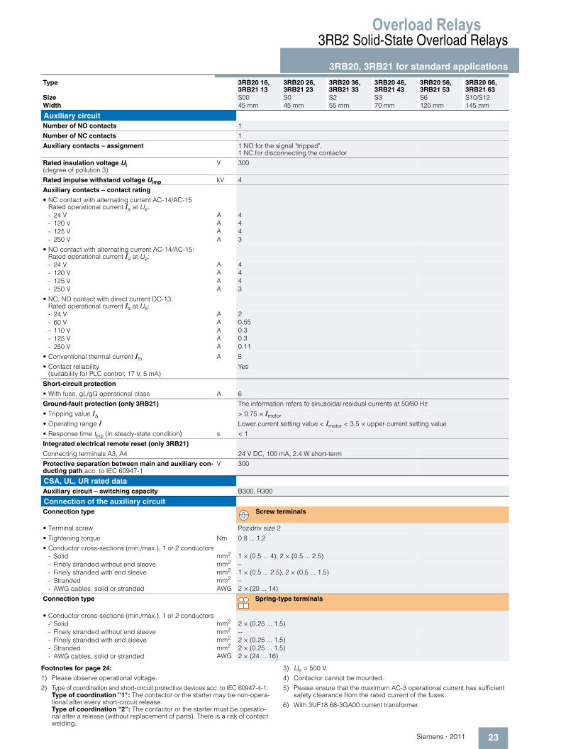
Size S00 S0 S2 S3 S6 S10/S12Width 45 mm 45 mm 55 mm 70 mm 120 mm 145 mm
Auxiliary circuitNumber of NO contacts 1
Number of NC contacts 1
Auxiliary contacts – assignment 1 NO for the signal "tripped", 1 NC for disconnecting the contactor
Rated insulation voltage Ui (degree of pollution 3)
V 300
Rated impulse withstand voltage Uimp kV 4
Auxiliary contacts – contact rating
• NC contact with alternating current AC-14/AC-15 Rated operational current Ie at Ue:- 24 V A 4- 120 V A 4- 125 V A 4- 250 V A 3
• NO contact with alternating current AC-14/AC-15: Rated operational current Ie at Ue:- 24 V A 4- 120 V A 4- 125 V A 4- 250 V A 3
• NC, NO contact with direct current DC-13: Rated operational current Ie at Ue:- 24 V A 2- 60 V A 0.55- 110 V A 0.3- 125 V A 0.3- 250 V A 0.11
• Conventional thermal current Ith A 5
• Contact reliability (suitability for PLC control; 17 V, 5 mA)
Yes
Short-circuit protection
• With fuse, gL/gG operational class A 6
Ground-fault protection (only 3RB21) The information refers to sinusoidal residual currents at 50/60 Hz
• Tripping value IΔ > 0.75 × Imotor
• Operating range I Lower current setting value < Imotor < 3.5 × upper current setting value
• Response time ttrip (in steady-state condition) s < 1
Integrated electrical remote reset (only 3RB21)
Connecting terminals A3, A4 24 V DC, 100 mA, 2.4 W short-term
Protective separation between main and auxiliary con-ducting path acc. to IEC 60947-1
V 300
CSA, UL, UR rated dataAuxiliary circuit – switching capacity B300, R300
Connection of the auxiliary circuitConnection type Screw terminals
• Terminal screw Pozidriv size 2
• Tightening torque Nm 0.8 ... 1.2
• Conductor cross-sections (min./max.), 1 or 2 conductors- Solid mm2 1 × (0.5 ... 4), 2 × (0.5 ... 2.5)- Finely stranded without end sleeve mm2 –- Finely stranded with end sleeve mm2 1 × (0.5 ... 2.5), 2 × (0.5 ... 1.5)- Stranded mm2 –- AWG cables, solid or stranded AWG 2 × (20 ... 14)
Connection type Spring-type terminals
• Conductor cross-sections (min./max.), 1 or 2 conductors- Solid mm2 2 × (0.25 ... 1.5)- Finely stranded without end sleeve mm2 --- Finely stranded with end sleeve mm2 2 × (0.25 ... 1.5)- Stranded mm2 2 × (0.25 ... 1.5)- AWG cables, solid or stranded AWG 2 × (24 ... 16)
Overload Relays3RB2 Solid-State Overload Relays3RB20, 3RB21 for standard applications
24 Siemens · 2011
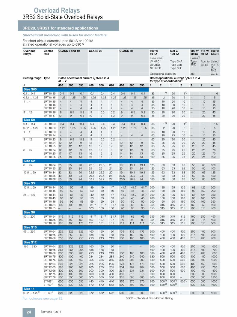
Short-circuit protection with fuses for motor feeders
For short-circuit currents up to 50 kA or 100 kA at rated operational voltages up to 690 V
For footnotes see page 23. SSCR = Standard Short-Circuit Rating
Overload relays
Contac-tors
CLASS 5 and 10 CLASS 20 CLASS 30 690 V/ 50 kA
690 V/ 100 kA
690 V/ 50 kA
415 V/ 50 kA
600 V/ SSCR
Fuse links1) Fuses1)
LV HRC Type 3NA Type 3ND
Acc. toBS 88
Listed acc. to UL, RK5
DIAZED Type 3SBNEOZED Type 3SE
Operational class gG aM CL. L
Setting range Type Rated operational current Ie /AC-3 in A at ... V
Rated operational current Ie/AC-3 in A for type of coordination2)
A 400 500 690 400 500 690 400 500 690 1 2 1 2 2 2 --
Size S000.1 ... 0.4 3RT10 15 0.4 0.4 0.4 0.4 0.4 0.4 0.4 0.4 0.4 35 13) 20 13) -- -- 1.60.32 ... 1.25 3RT10 15 1.25 1.25 1.25 1.25 1.25 1.25 1.25 1.25 1.25 35 2 20 2 -- 2 51 ... 4 3RT10 15 4 4 4 4 4 4 4 4 4 35 10 20 10 -- 10 15
3RT10 16 4 4 4 4 4 4 4 4 4 35 10 20 10 -- 10 153RT10 17 4 4 4 4 4 4 4 4 4 35 10 20 10 -- 10 15
3 ... 12 3RT10 16 9 6.5 5.2 9 6.5 5.2 9 6.5 5.2 35 20 20 20 -- 20 453RT10 17 12 9 6.3 10 9 6.3 9 9 6.3 35 20 20 20 -- 20 45
Size S00.1 ... 0.4 3RT10 23 0.4 0.4 0.4 0.4 0.4 0.4 0.4 0.4 0.4 35 13) 20 13) -- -- 1.60.32 ... 1.25 3RT10 23 1.25 1.25 1.25 1.25 1.25 1.25 1.25 1.25 1.25 35 2 20 2 -- 2 51 ... 4 3RT10 23 4 4 4 4 4 4 -- -- -- 63 10 20 10 -- 10 15
3RT10 24 4 4 4 4 4 4 4 4 4 63 10 25 10 -- 10 153 ... 12 3RT10 23 9 6.5 5.2 9 6.5 5.2 -- -- -- 63 25 20 20 -- 20 45
3RT10 24 12 12 9 12 12 9 12 12 9 63 25 25 20 20 20 453RT10 25 12 12 12 12 12 12 12 12 12 63 25 25 20 20 20 45
6 ... 25 3RT10 24 12 12 9 12 12 9 12 12 9 63 25 25 25 20 25 703RT10 25 17 17 13 16 16 13 14 14 13 63 25 25 25 20 25 703RT10 26 25 18 13 16 16 13 14 14 13 100 35 35 35 20 25 100
Size S26 ... 25 3RT10 34 25 25 20 22.3 22.3 20 19.1 19.1 19.1 125 63 63 63 50 63 100
3RT10 35 25 25 24 25 25 24 25 25 24 125 63 63 63 50 80 10012.5 ... 50 3RT10 34 32 32 20 22.3 22.3 20 19.1 19.1 19.1 125 63 63 63 50 63 125
3RT10 35 40 40 24 29.4 29.4 24 26.5 26.5 24 125 63 63 63 50 80 1503RT10 36 50 50 24 32.7 32.7 24 26.5 26.5 24 160 80 80 80 50 80 200
Size S312.5 ... 50 3RT10 44 50 50 47 49 49 47 41.7 41.7 41.7 200 125 125 125 63 125 200
3RT10 45 50 50 50 50 50 50 45 45 45 200 160 160 160 80 160 20025 ... 100 3RT10 44 65 65 47 49 49 47 41.7 41.7 41.7 200 125 125 125 63 125 250
3RT10 45 80 80 58 53 53 53 45 45 45 200 160 160 160 80 160 3003RT10 46 95 95 58 59 59 58 50 50 50 200 160 160 160 100 160 3503RT10 54 100 100 100 81.7 81.7 81.7 69 69 69 355 315 315 315 160 250 4003RT10 55 -- -- -- 100 100 100 90 90 90 355 315 315 315 200 315 400
Size S650 ... 200 3RT10 54 115 115 115 81.7 81.7 81.7 69 69 69 355 315 315 315 160 250 450
3RT10 55 150 150 150 107 107 107 90 90 90 355 315 315 315 200 315 5003RT10 56 185 185 170 131 131 131 111 111 111 355 315 315 315 200 315 500
Size S1055 ... 250 3RT10 64 225 225 225 160 160 160 135 135 135 500 400 400 400 250 400 600
3RT10 65 250 250 250 188 188 188 159 159 159 500 400 400 400 315 400 7003RT10 66 250 250 250 213 213 213 180 180 180 500 400 400 400 315 400 700
Size S12160 ... 630 3RT10 64 225 225 225 160 160 160 -- -- -- 500 400 400 400 250 400 600
3RT10 65 265 265 265 188 188 188 -- -- -- 500 400 400 400 315 400 7003RT10 66 300 300 280 213 213 213 180 180 180 500 400 400 400 315 400 8003RT10 75 400 400 400 284 284 284 240 240 240 630 500 500 500 400 450 10003RT10 76 500 500 450 355 355 355 300 300 300 630 500 500 500 500 500 12003RT12 64 225 225 225 225 225 225 173 173 173 500 500 500 500 400 450 6003RT12 65 265 265 265 265 265 265 204 204 204 500 500 500 500 400 450 7003RT12 66 300 300 300 300 300 300 231 231 231 500 500 500 500 400 450 8003RT12 75 400 400 400 400 400 400 316 316 316 800 800 800 -- 630 800 10003RT12 76 500 500 500 500 500 500 385 385 385 800 800 800 -- 630 800 12003TF684) 630 630 630 440 440 440 376 376 376 800 5005) 5005) 5005) 630 500 16003TF694) 630 630 630 572 572 572 500 500 500 800 6305) 6305) -- 630 630 1600
Size 140.32 ... 1.256) 3TF694) 820 820 820 572 572 572 500 500 500 800 6305) 6305) -- 630 630 1600
Overload Relays
25Siemens · 2011
3RB2 Solid-State Overload Relays
3RB20, 3RB21 for standard applications
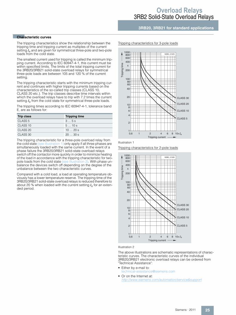
■Characteristic curves
The tripping characteristics show the relationship between the tripping time and tripping current as multiples of the current setting Ie and are given for symmetrical three-pole and two-pole loads from the cold state.
The smallest current used for tripping is called the minimum trip-ping current. According to IEC 60947-4-1, this current must be within specified limits. The limits of the total tripping current for the 3RB20/3RB21 solid-state overload relays for symmetrical three-pole loads are between 105 and 120 % of the current setting.
The tripping characteristic starts with the minimum tripping cur-rent and continues with higher tripping currents based on the characteristics of the so-called trip classes (CLASS 10, CLASS 20 etc.). The trip classes describe time intervals within which the overload relays have to trip with 7.2 times the current setting Ie from the cold state for symmetrical three-pole loads.
The tripping times according to IEC 60947-4-1, tolerance band E, are as follows for:
The tripping characteristic for a three-pole overload relay from the cold state (see illustration 1) only apply if all three phases are simultaneously loaded with the same current. In the event of a phase failure the 3RB20/3RB21 solid-state overload relays switch off the contactor more quickly in order to minimize heating of the load in accordance with the tripping characteristic for two-pole loads from the cold state (see illustration 2). With phase un-balance the devices switch off depending on the degree of the unbalance between the two characteristic curves.
Compared with a cold load, a load at operating temperature ob-viously has a lower temperature reserve. The tripping time of the 3RB20/3RB21 solid-state overload relays is reduced therefore to about 20 % when loaded with the current setting Ie for an exten-ded period.
Tripping characteristics for 3-pole loads
Illustration 1
Tripping characteristics for 2-pole loads
Illustration 2
The above illustrations are schematic representations of charac-teristic curves. The characteristic curves of the individual 3RB20/3RB21 electronic overload relays can be ordered from "Technical Assistance":• Either by e-mail to:
[email protected]• Or on the Internet at:
http://www.siemens.com/automation/service&support
Trip class Tripping time
CLASS 5 3 … 5 s
CLASS 10 5 … 10 s
CLASS 20 10 … 20 s
CLASS 30 20 … 30 s
NSB0_01525
1
2
4
68
10
20
40
6080
100
200
400
600800
1000
0,6 1 2 4 6 8 10× e
s
CLASS 30
CLASS 20
CLASS 10
CLASS 5
Tripping current
Trip
ping
tim
e
NSB0_01526
1
2
4
68
10
20
40
6080
100
200
400
600800
1000
0,6 1 2 4 6 8 10× e
s
CLASS 30
CLASS 20
CLASS 10
CLASS 5
Tripping current
Trip
ping
tim
e
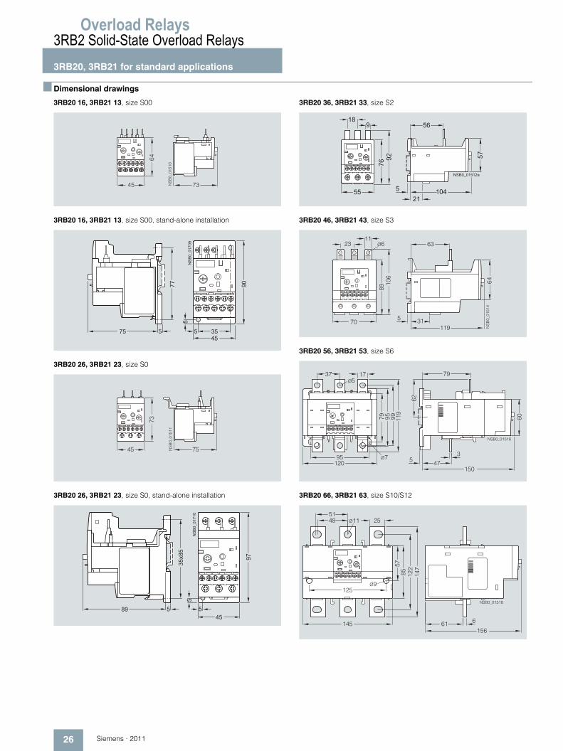
Overload Relays3RB2 Solid-State Overload Relays3RB20, 3RB21 for standard applications
26 Siemens · 2011
■ Dimensional drawings
3RB20 16, 3RB21 13, size S00
3RB20 16, 3RB21 13, size S00, stand-alone installation
3RB20 26, 3RB21 23, size S0
3RB20 26, 3RB21 23, size S0, stand-alone installation
3RB20 36, 3RB21 33, size S2
3RB20 46, 3RB21 43, size S3
3RB20 56, 3RB21 53, size S6
3RB20 66, 3RB21 63, size S10/S12
45 73NS
B0_
0151
0
64
NS
B0_
0170
9
45
77 90
3575 55
5
45 75NS
B0_
0151
1
73
NS
B0_
0171
0
45
35x8
5
97
89 55
5
76
55
9 5618
521
104
92 57
NSB0_01512a
2311
70
8910
6
5 31119
64
63
NS
B0_
0151
4
Ø6
37 1779 95 99 11
9
95 Ø7
60
5 47
79
62
3
120150
Ø5
NSB0_01516
48 Ø1151
25
125
5785 12
214
7
145 61 6
156
Ø9
NSB0_01518
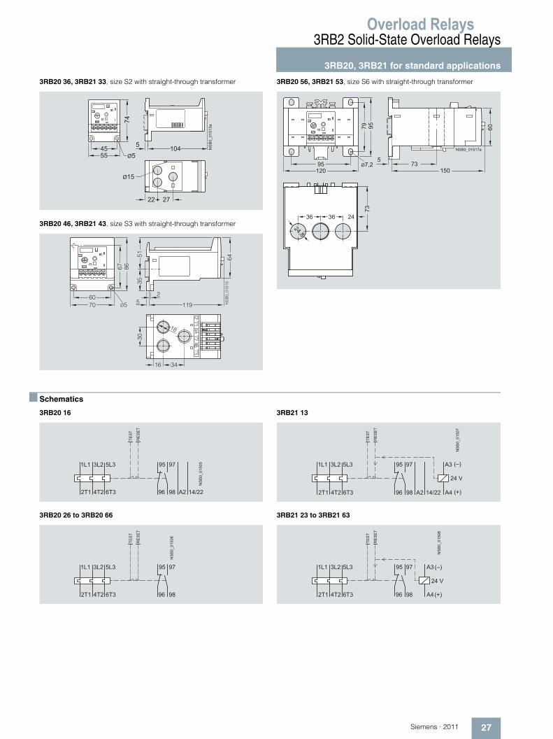
Overload Relays
27Siemens · 2011
3RB2 Solid-State Overload Relays
3RB20, 3RB21 for standard applications
3RB20 36, 3RB21 33, size S2 with straight-through transformer
3RB20 46, 3RB21 43, size S3 with straight-through transformer
3RB20 56, 3RB21 53, size S6 with straight-through transformer
■ Schematics
3RB20 16
3RB20 26 to 3RB20 66
3RB21 13
3RB21 23 to 3RB21 63
NS
B0_
0151
3a
55
74
45 1045
27
Ø15
Ø5
22
18
7060
67 86
5 119
3530
16 34
51
2
64
Ø5 NS
B0_
0151
5
12095
36
15073
5Ø7,2
73
36
24,8
24
79 95 60
NSB0_01517a
�
� �
� �
� � � � � � � �
��������
� � � � �� � �
� � � � �
����
�����
�
� �
� �
� �
���������
� � � � �� � �
� � � � �
����
�����
�
� �
� �
� � � � � � � �
���������
� � � � �� � �
� � � � �
����
�����
� �
�
! " #
� � $
! % #
�
� �
� �
� �
���������
� � � � �� � �
� � � � �
����
�����
� �
�
! " #
� � $
! % #
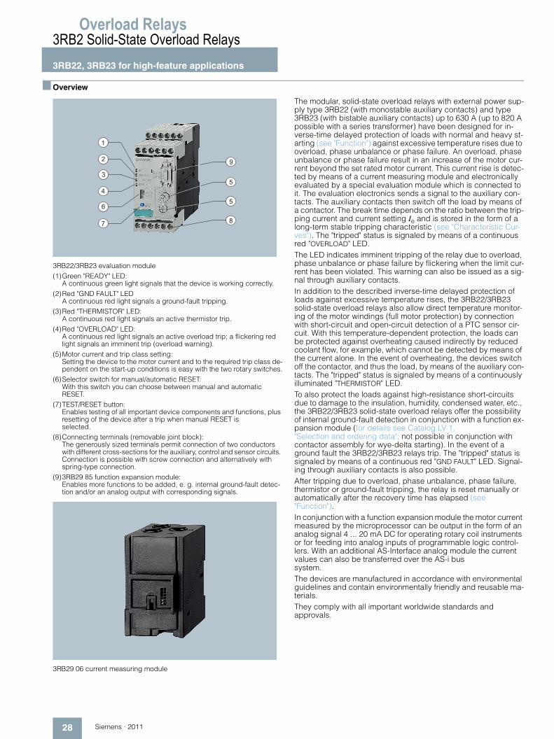
Overload Relays3RB2 Solid-State Overload Relays3RB22, 3RB23 for high-feature applications
28 Siemens · 2011
■ Overview
3RB22/3RB23 evaluation module(1)Green "READY" LED:
A continuous green light signals that the device is working correctly.(2)Red "GND FAULT" LED
A continuous red light signals a ground-fault tripping.(3)Red "THERMISTOR" LED:
A continuous red light signals an active thermistor trip.(4)Red "OVERLOAD" LED:
A continuous red light signals an active overload trip; a flickering red light signals an imminent trip (overload warning).
(5)Motor current and trip class setting: Setting the device to the motor current and to the required trip class de-pendent on the start-up conditions is easy with the two rotary switches.
(6)Selector switch for manual/automatic RESET: With this switch you can choose between manual and automatic RESET.
(7)TEST/RESET button: Enables testing of all important device components and functions, plus resetting of the device after a trip when manual RESET isselected.
(8)Connecting terminals (removable joint block): The generously sized terminals permit connection of two conductors with different cross-sections for the auxiliary, control and sensor circuits. Connection is possible with screw connection and alternatively with spring-type connection.
(9)3RB29 85 function expansion module: Enables more functions to be added, e. g. internal ground-fault detec-tion and/or an analog output with corresponding signals.
3RB29 06 current measuring module
The modular, solid-state overload relays with external power sup-ply type 3RB22 (with monostable auxiliary contacts) and type 3RB23 (with bistable auxiliary contacts) up to 630 A (up to 820 A possible with a series transformer) have been designed for in-verse-time delayed protection of loads with normal and heavy st-arting (see "Function") against excessive temperature rises due to overload, phase unbalance or phase failure. An overload, phase unbalance or phase failure result in an increase of the motor cur-rent beyond the set rated motor current. This current rise is detec-ted by means of a current measuring module and electronically evaluated by a special evaluation module which is connected to it. The evaluation electronics sends a signal to the auxiliary con-tacts. The auxiliary contacts then switch off the load by means of a contactor. The break time depends on the ratio between the trip-ping current and current setting Ie and is stored in the form of a long-term stable tripping characteristic (see "Characteristic Cur-ves"). The "tripped" status is signaled by means of a continuous red "OVERLOAD" LED.The LED indicates imminent tripping of the relay due to overload, phase unbalance or phase failure by flickering when the limit cur-rent has been violated. This warning can also be issued as a sig-nal through auxiliary contacts.In addition to the described inverse-time delayed protection of loads against excessive temperature rises, the 3RB22/3RB23 solid-state overload relays also allow direct temperature monitor-ing of the motor windings (full motor protection) by connection with short-circuit and open-circuit detection of a PTC sensor cir-cuit. With this temperature-dependent protection, the loads can be protected against overheating caused indirectly by reduced coolant flow, for example, which cannot be detected by means of the current alone. In the event of overheating, the devices switch off the contactor, and thus the load, by means of the auxiliary con-tacts. The "tripped" status is signaled by means of a continuously illuminated "THERMISTOR" LED.To also protect the loads against high-resistance short-circuits due to damage to the insulation, humidity, condensed water, etc., the 3RB22/3RB23 solid-state overload relays offer the possibility of internal ground-fault detection in conjunction with a function ex-pansion module (for details see Catalog LV 1, "Selection and ordering data"; not possible in conjunction with contactor assembly for wye-delta starting). In the event of a ground fault the 3RB22/3RB23 relays trip. The "tripped" status is signaled by means of a continuous red "GND FAULT" LED. Signal-ing through auxiliary contacts is also possible.After tripping due to overload, phase unbalance, phase failure, thermistor or ground-fault tripping, the relay is reset manually or automatically after the recovery time has elapsed (see "Function").In conjunction with a function expansion module the motor current measured by the microprocessor can be output in the form of an analog signal 4 ... 20 mA DC for operating rotary coil instruments or for feeding into analog inputs of programmable logic control-lers. With an additional AS-Interface analog module the current values can also be transferred over the AS-i bus system.The devices are manufactured in accordance with environmental guidelines and contain environmentally friendly and reusable ma-terials.They comply with all important worldwide standards and approvals.
1
2
3
4
9
5
5
8
6
7
Overload Relays
29Siemens · 2011
3RB2 Solid-State Overload Relays
3RB22, 3RB23 for high-feature applications
"Increased safety" type of protection EEx e acc. to ATEX di-rective 94/9/EC
The 3RB22 (monostable) solid-state overload relays are suitable for the overload protection of explosion-proof motors with "incre-ased safety" type of protection EEx e; see Catalog LV 1, Chapter 20 "Appendix" --> "Standards and Ap-provals" --> "Type Overview of Approved Devices for Explosion-Protected Areas (ATEX Explosion Protection)".
■ Design
Device concept
The 3RB22/3RB23 solid-state overload relays are based on a modular device concept. Each device always comprises an eva-luation module, which is independent of the motor current, and a current measuring module, which is dependent on the motor current. The two modules are electrically interconnected by a connection cable through the system interface.
The basic functionality of the evaluation module can be optio-nally expanded with corresponding function expansion modu-les. The function expansion modules are integrated in the evalu-ation module for this purpose through a simple plug-in connection.
Mounting options
Current measuring modules
The current measuring modules size S00/S0 and S2/S3 are de-signed for stand-alone installation. By contrast, the current measuring modules size S6 and S10/S12 are suitable for stand-alone installation and mounting onto contactors.
Evaluation modules
The evaluation modules can be mounted either on the current measuring module (only sizes S00/S0 and S2/S3) or separately.
For more information on the mounting options see "Technical specifications" and Catalog LV 1, "Selection and ordering data".
Connection methods
Main circuit (current measuring module)
For sizes S00/S0, S2/S3 and S6, the main circuit can also be connected by the straight-through transformer method. In this case, the cables of the main circuit are routed directly through the feed-through openings of the relay to the contactorterminals.
For sizes S6 and S10/S12, the main circuit can be connected with the help of rails. In conjunction with the corresponding box terminals, screw connection is also possible.
Auxiliary circuit (evaluation module)
Connection of the auxiliary circuit (removable joint block) is pos-sible with either screw or spring-type terminal connection sys-tem (special versions).
For more information on the connection options see "Technical specifications" and Catalog LV 1, "Selection and ordering data".
Overload relays in contactor assemblies for wye-delta starting
When overload relays are used in combination with contactor assemblies for wye-delta starting it must be noted that only 0.58 times the motor current flows through the line contactor. An overload relay mounted onto the line contactor must be set to 0.58 times the motor current.
When 3RB22/3RB23 solid-state overload relays are used in combination with contactor assemblies for wye-delta starting, the function expansion modules for internal ground-fault detec-tion must not be used.
Operation with frequency converter
The 3RB22/3RB23 solid-state overload relays are suitable for fre-quencies of 50/60 Hz and the associated harmonics. This per-mits the 3RB22/3RB23 overload relays to be used on the input side of the frequency converter.
If motor protection is required on the outgoing side of the fre-quency converter, Siemens recommends the 3RN thermistor motor protection devices or the 3RU11 thermal overload relays for this purpose.
Overload Relays3RB2 Solid-State Overload Relays3RB22, 3RB23 for high-feature applications
30 Siemens · 2011
■ Function
Basic functions
The 3RB22/3RB23 solid-state overload relays are designed for:• Inverse-time delayed protection of loads from overloading• Inverse-time delayed protection of loads from phase
unbalance• Inverse-time delayed protection of loads from phase failure• Temperature-dependent protection of loads by connecting a
PTC sensor circuit• Protection of loads from high-resistance short-circuits (internal
ground-fault detection; detection of fault currents > 30 % of the current setting Ie)
• Output of an overload warning• Output of an analog signal 4 to 20 mA DC as image of the flow-
ing motor current
The basic functions of the evaluation modules in conjunction with function expansion modules are listed in the following table:
Control circuit
The 3RB22/3RB23 solid-state overload relays require an external power supply, i. e. an additional supply voltage is necessary. Po-wer is supplied through a wide-range power supply unit for 24 to 240 V AC/DC.
Short-circuit protection
Fuses or motor starter protectors must be used for short-circuit protection.
For assignments of the corresponding short-circuit protection de-vices to the 3RB22/3RB23 solid-state overload relays with/without contactor see "Technical specifications" and Catalog LV 1, "Selection and ordering data".
Trip classes
The 3RB22/3RB23 solid-state overload relays are suitable for nor-mal and heavy starting conditions. The required trip class (CLASS 5, 10, 20 or 30) can be adjusted by means of a rotary switch depending on the current start-up condition.
For details of the trip classes see "Characteristic Curves".
Phase failure protection
The 3RB22/3RB23 solid-state overload relays are fitted with phase failure protection (see "Characteristic Curves") in order to mini-mize temperature rises of the load during single-phase operation.
Setting
The 3RB22/3RB23 solid-state overload relays are set to the rated motor current by means of two rotary knobs.• The upper rotary knob (CLASS/Iemax) is divided into 4 ranges:
1 A, 10 A, 100 A and 1000 A. The zone must be selected which corresponds to the rated motor current and the current measu-ring module to be used with it. With the range selected the re-quired trip class (CLASS 5, 10, 20 or 30) can be determined.
• The lower rotary knob with percent scale (10 ... 100 %) is then used to set the rated motor current in percent of the range se-lected with the upper rotary knob.
Example• Rating of induction motor = 45 kW (AC 50 Hz, 400 V)• Rated motor current = 80 A• Required trip class = CLASS 20• Selected transformer: 10 ... 100 A
Solution• Step 1: Use the upper rotary knob (CLASS) to select the 100 A
range• Step 2: Within the 100 A range set the trip class CLASS 20• Step 3: Set the lower rotary knob to 80 % (= 0.8) corresponding
to 100 A × 0.8 = 80 A.
If the current which is set on the evaluation module does not cor-respond to the current range of the connected current transfor-mer, an error will result.
Manual and automatic reset
In the case of the 3RB22/3RB23 solid-state overload relays, a slide switch can be used to choose between automatic and ma-nual resetting.
If manual reset is set, a reset can be carried out directly on the de-vice after a trip by pressing the blue TEST/RESET button. A remote RESET can be carried out electrically by jumpering the terminals Y1 and Y2.
If the slide switch is set to automatic RESET, the relay is reset au-tomatically.
The time between tripping and resetting is determined by the re-covery time.
Evaluation modules
Function expan-sion modules
Basic functions
3RB22 83-4AA1
3RB22 83-4AC1
3RB23 83-4AA1
3RB23 83-4AC1
None Inverse-time delayed protection, temperature-dependent protection, electrical remote RESET, overload warning
3RB29 85-2CA1 Inverse-time delayed protection, temperature-dependent protection, internal ground-fault detection, electrical remote RESET, overload warning
3RB29 85-2CB1 Inverse-time delayed protection, temperature-dependent protection, internal ground-fault detection, electrical remote RESET, ground-fault signal
3RB29 85-2AA0 Inverse-time delayed protection, temperature-dependent protection, electrical remote RESET, overload warning, analog output
3RB29 85-2AA1 Inverse-time delayed protection, temperature-dependent protection, internal ground-fault detection, electrical remote RESET, overload warning, analog output
3RB29 85-2AB1 Inverse-time delayed protection, temperature-dependent protection, internal ground-fault detection, electrical remote RESET, ground-fault signal, analog output
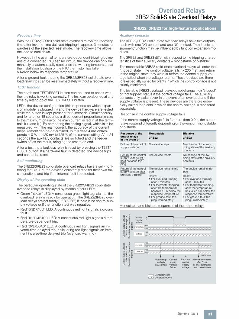
Overload Relays
31Siemens · 2011
3RB2 Solid-State Overload Relays
3RB22, 3RB23 for high-feature applications
Recovery time
With the 3RB22/3RB23 solid-state overload relays the recovery time after inverse-time delayed tripping is approx. 3 minutes re-gardless of the selected reset mode. The recovery time allows the load to cool down.
However, in the event of temperature-dependent tripping by me-ans of a connected PTC sensor circuit, the device can only be manually or automatically reset once the winding temperature at the installation location of the PTC thermistor has fallen 5 Kelvin below its response temperature.
After a ground-fault tripping the 3RB22/3RB23 solid-state over-load relay trips can be reset immediately without a recovery time.
TEST function
The combined TEST/RESET button can be used to check whe-ther the relay is working correctly. The test can be aborted at any time by letting go of the TEST/RESET button.
LEDs, the device configuration (this depends on which expan-sion module is plugged in) and the device hardware are tested while the button is kept pressed for 6 seconds. Simultaneously and for another 18 seconds a direct current proportional in size to the maximum phase of the main current is fed in at the termi-nals I(+) and I(-). By comparing the analog signal, which is to be measured, with the main current, the accuracy of the current measurement can be determined. In this case 4 mA corres-ponds to 0 % and 20 mA to 125 % of the current setting. After 24 seconds the auxiliary contacts are switched and the feeder switch off as the result, bringing the test to an end.
After a test trip a faultless relay is reset by pressing the TEST/RESET button. If a hardware fault is detected, the device trips and cannot be reset.
Self-monitoring
The 3RB22/3RB23 solid-state overload relays have a self-moni-toring feature, i. e. the devices constantly monitor their own ba-sic functions and trip if an internal fault is detected.
Display of the operating state
The particular operating state of the 3RB22/3RB23 solid-state overload relays is displayed by means of four LEDs:• Green "READY" LED: A continuous green light signals that the
overload relay is ready for operation. The 3RB22/3RB23 over-load relays are not ready (LED "OFF") if there is no control sup-ply voltage or if the function test was negative.
• Red "GND FAULT" LED: A continuous red light signals a ground fault.
• Red "THERMISTOR" LED: A continuous red light signals a tem-perature-dependent trip.
• Red "OVERLOAD" LED: A continuous red light signals an in-verse-time delayed trip; a flickering red light signals an immi-nent inverse-time delayed trip (overload warning).
Auxiliary contacts
The 3RB22/3RB23 solid-state overload relays have two outputs, each with one NO contact and one NC contact. Their basic as-signment/function may be influenced by function expansion mo-dules.
The 3RB22 and 3RB23 differ with respect to the tripping charac-teristics of their auxiliary contacts – monostable or bistable:
The monostable 3RB22 solid-state overload relays will enter the "tripped" state if the control voltage fails (> 200 ms), and return to the original state they were in before the control supply vol-tage failed when the voltage returns. These devices are there-fore especially suited for plants in which the control voltage is not strictly monitored.
The bistable 3RB23 overload relays do not change their "tripped" or "not tripped" status if the control voltage fails. The auxiliary contacts only switch over in the event of an overload and if the supply voltage is present. These devices are therefore espe-cially suited for plants in which the control voltage is monitored separately.
Response if the control supply voltage fails
If the control supply voltage fails for more than 0.2 s, the output relays respond differently depending on the version: monostable or bistable.
Monostable and bistable responses of the output relays
Response of the output relays in the event of
Monostable
3RB22
Bistable
3RB23
Failure of the control supply voltage
The device trips No change of the swit-ching state of the auxiliary contacts
Return of the control supply voltage wit-hout previous trip-ping
The device resets No change of the swit-ching state of the auxiliary contacts
Return of the control supply voltage after previous tripping
The device remains trip-ped
Reset:• For overload tripping,
after 3 minutes• For thermistor tripping,
after the temperature has fallen 5 K below the response temperature
• For ground-fault trip-ping, immediately
The device remains trip-ped
Reset:• For overload tripping,
after 3 minutes• For thermistor tripping,
after the temperature has fallen 5 K below the response temperature
• For ground-fault trip-ping, immediately
NSB0_01628
t
&'()*'+�,-..+/�0'+)�1��
2�3+-
*���
����.*3'*�
)4�*5
3,)'*�'*�'0�*6-**�()�
)*3..3(1�
&'()*'+�,-..+/�0'+)�1�
2�3+-
*���
�������.*3'*�
)4�*5
3,)'*�'*�'0�*6-**�()�
)*3..3(1
Control supplyvoltage
monostable
monostable
bistable
bistable
� ' ) ' * � ) � 5 . 7) ' ' � 4 3 1 4 8
9 � 0 3 6 � � ) * 3 . ,
& ' ( ) * ' +, - . . + / �0 ' + ) � 1 �2 � 3 + - * �
� � ) - * ( � ' 2 �6 ' ( ) * ' +, - . . + /0 ' + ) � 1 �
� � ( - � + � � - ) ' � * � , � ) �� 2 ) � * � � � 5 3 ( �
' * � � 2 ) � * � ) 4 � * 5 3 , ) ' * �4 � , � 6 ' ' + � 9 � 9 ' : (
& ' ( ) � 6 ) ' * � ' . � (
& ' ( ) � 6 ) ' * � 6 + ' , � 9
NC
NO
NC
NO
NC
NO
NCNO
01
Overload Relays3RB2 Solid-State Overload Relays3RB22, 3RB23 for high-feature applications
32 Siemens · 2011
■ Technical specifications
1) On request.
2) Current measuring modules size S6 and S10/S12 with busbar connection in conjunction with cover.
Type – Overload relay of complete system 3RB22, 3RB23
Size S00 ... S10/S12
General dataTrips in the event of Overload, phase failure and phase unbalance (> 40 % acc. to NEMA),
+ ground fault (with corresponding function expansion module) and activation of the thermistor motor protection (with closed PTC sensor circuit)
Trip class acc. to IEC 60947-4-1 CLASS 5, 10, 20 and 30 adjustable
Phase failure sensitivity Yes
Overload warning Yes, from 1.125 x Ie for symmetrical loads and from 0.85 x Ie for unsymmetrical loads
Reset and recovery• Reset options after tripping Manual, automatic and remote RESET• Recovery time
- For automatic RESET min - For tripping due to overcurrent: 3 (stored permanently) - For tripping by thermistor: time until the motor temperature has fallen 5 K below the response temperature
- For tripping due to a ground fault: no automatic RESET- For manual RESET min - For tripping due to overcurrent: 3 (stored permanently)
- For tripping by thermistor: time until the motor temperature has fallen 5 K below the response temperature
- For tripping due to a ground fault: immediately- For remote RESET min - For tripping due to overcurrent: 3 (stored permanently)
- For tripping by thermistor: time until the motor temperature has fallen 5 K below the response temperature
- For tripping due to a ground fault: immediately
Features• Display of operating state on device Yes, with 4 LEDs: Green "Ready" LED, red "Ground Fault" LED,
red "Thermistor" LED and red "Overload" LED• TEST function Yes, test of LEDs, electronics, auxiliary contacts and wiring of control circuit by press-
ing the button TEST/RESET / self-monitoring• RESET button Yes, with the TEST/RESET button• STOP button No
Explosion protection – safe operation of motors with "increased safety" type of protection
EC type test certificate number acc. to directive 94/9/EC (ATEX)
PTB 05 ATEX 3022 II (2) GD
Ambient temperatures
• Storage/transport °C -40 ... +80
• Operation °C -25 ... +60
• Temperature compensation °C +60
• Permissible rated current- Temperature inside control cabinet 60 °C % 100- Temperature inside control cabinet 70 °C % 1)
Repeat terminals• Coil repeat terminal Not required• Auxiliary contact repeat terminal Not required
Degree of protection acc. to IEC 60529 IP202)
Touch protection acc. to IEC 61140 Finger-safe2)
Shock resistance with sine acc. to IEC 60068-2-27 g/ms 15/11
Electromagnetic compatibility (EMC) – Interference immunity• Conductor-related interference
- Burst acc. to IEC 61000-4-4 (corresponds to degree of severity 3)
kV 2 (power ports), 1 (signal ports)
- Surge acc. to IEC 61000-4-5 (corresponds to degree of severity 3)
kV 2 (line to earth), 1 (line to line)
• Electrostatic discharge acc. to IEC 61000-4-2 (corresponds to degree of severity 3)
kV 8 (air discharge), 6 (contact discharge)
• Field-related interference acc. to IEC 61000-4-3 (corresponds to degree of severity 3)
V/m 10
Electromagnetic compatiblity (EMC) – emitted interference
Degree of severity A acc. to EN 55011 (CISPR 11) and EN 55022 (CISPR 22)
Resistance to extreme climates – air humidity % 100
Dimensions See dimensional drawings
Installation altitude above sea level m Up to 2000
Mounting position Any
Type of mounting Evaluation module: stand-alone installation, current measuring module size S00 to S3: stand-alone installation, current measuring module size S6 and S10/S12: stand-alone installation and moun-ting onto contactors
Overload Relays
33Siemens · 2011
3RB2 Solid-State Overload Relays
3RB22, 3RB23 for high-feature applications
1) For grounded networks, otherwise 600 V.
2) When connecting cable lugs according to DIN 46235, use the 3RT19 56-4EA1 terminal cover for conductor cross-sections from 95 mm2 to ensure phase spacing.
3) When connecting cable lugs according to DIN 46234 for conductor cross-sections from 240 mm2 as well as DIN 46235 for conductor cross-sections from 185 mm2, use the 3RT19 56-4EA1 terminal cover to ensure phase spacing.
Type – Overload relay of current measuring module 3RB29 06 3RB29 06 3RB29 56 3RB29 66
Size S00/S0 S2/S3 S6 S10/S12
Width 45 mm 55 mm 120 mm 145 mm
Main circuitRated insulation voltage Ui (degree of pollution 3)
V 1000
Rated impulse withstand voltage Uimp kV 6 8
Rated operational voltage Ue V 1000
Type of current• Direct current No• Alternating current Yes, 50/60 Hz ±5 %
Current setting A 0.3 ... 3; 2.4 ... 25
10 ... 100 20 ... 200 63 ... 630
Power loss per unit (max.) W 0.5
Short-circuit protection• With fuse without contactor See Catalog LV 1, "Selection and ordering data".• With fuse and contactor See "Technical specifications" (short-circuit protection with fuses for motor feeders)
Protective separation between main and auxiliary conducting path acc. to IEC 60947-1 (degree of pollution 2)
V 6901)
Connection for main circuitConnection type Screw terminals with box terminal
• Terminal screw -- 4 mm Allen screw 5 mm Allen screw
• Tightening torque Nm -- 10 ... 12 20 ... 22
• Conductor cross-sections (min./max.), 1 or 2 conductors- Solid mm2 -- -- --- Finely stranded without end sleeve mm2 -- With 3RT19 55-4G box terminal:
2 × (1 × max. 50, 1 × max. 70), 1 × (10 ... 70)With 3RT19 56-4G box terminal: 2 × (1 × max. 95, 1 × max. 120), 1 × (10 ... 120)
2 × (50 ... 185), Front clamping point only: 1 × (70 ... 240)Rear clamping point only: 1 × (120 ... 185)
- Finely stranded with end sleeve mm2 -- With 3RT19 55-4G box terminal: 2 × (1 × max. 50, 1 × max. 70), 1 × (10 ... 70)With 3RT19 56-4G box terminal: 2 × (1 × max. 95, 1 × max. 120), 1 × (10 ... 120)
2 × (50 ... 185), Front clamping point only: 1 × (70 ... 240)Rear clamping point only: 1 × (120 ... 185)
- Stranded mm2 -- With 3RT19 55-4G box terminal: 2 × (max. 70), 1 × (16 ... 70)With 3RT19 56-4G box terminal: 2 × (max. 120), 1 × (16 ... 120)
2 × (70 ... 240), Front clamping point only: 1 × (95 ... 300)Rear clamping point only: 1 × (120 ... 240)
- AWG cables, solid or stranded AWG -- With 3RT19 55-4G box terminal: 2 × (max. 1/0), 1 × (6 ... 2/0)With 3RT19 56-4G box terminal: 2 × (max. 3/0), 1 × (6 ... 250 kcmil)
2 × (2/0 ... 500 kcmil), Front clamping point only: 1 × (3/0 ... 600 kcmil)Rear clamping point only: 1 × (250 kcmil ... 500 kcmil)
- Ribbon cable conductors (number x width x thickness)
mm -- With 3RT19 55-4G box terminal: 2 × (6 × 15.5 × 0.8), 1 × (3 × 9 × 0.8 ... 6 × 15.5 × 0.8)With 3RT19 56-4G box terminal: 2 × (10 × 15.5 × 0.8), 1 × (3 × 9 × 0.8 ... 10 × 15.5 × 0.8)
2 × (20 × 24 × 0.5), 1 × (6 × 9 × 0.8 ... 20 × 24 × 0.5)
Connection type Busbar connections
• Terminal screw -- M8 × 25 M10 × 30
• Tightening torque Nm -- 10 ... 14 14 ... 24
• Conductor cross-section (min./max.)- Solid with cable lug mm2 -- 16 ... 95 2) 50 ... 240 3)
- Stranded with cable lug mm2 -- 25 ... 120 2) 70 ... 240 3)
- AWG cables, solid or stranded, with cable lug
AWG -- 4 ... 250 kcmil 2/0 ... 500 kcmil
- With connecting bar (max. width) mm -- 15 25
Connection type Straight-through transformers
Diameter of opening mm 7.5 14 25 --
Overload Relays3RB2 Solid-State Overload Relays3RB22, 3RB23 for high-feature applications
34 Siemens · 2011
1) The assignment of auxiliary contacts may be influenced by function expan-sion modules.
Type – Overload relay of evaluation module 3RB22 83, 3RB23 83
Size S00 ... S10/S12
Width 45 mm
Auxiliary circuitNumber of NO contacts 2
Number of NC contacts 2
Auxiliary contacts – assignment 1 NO for the signal "tripped due to overload and/or thermistor",1 NC for switching off the contactor1 NO for the signal "tripped due to ground fault",1 NC for switching off the contactor
or1)
1 NO for the signal "tripped due to overload and/or thermistor and/or ground fault",1 NC for switching off the contactor1 NO for overload warning,1 NC for switching off the contactor
Rated insulation voltage Ui (degree of pollution 3)
V 300
Rated impulse withstand voltage Uimp kV 4
Auxiliary contacts – contact rating
• NC contact with alternating current AC-14/AC-15 Rated operational current Ie at Ue:- 24 V A 6- 120 V A 6- 125 V A 6- 250 V A 3
• NO contact with alternating current AC-14/AC-15: Rated operational current Ie at Ue:- 24 V A 6- 120 V A 6- 125 V A 6- 250 V A 3
• NC, NO contact with direct current DC-13: Rated operational current Ie at Ue:- 24 V A 2- 60 V A 0.55- 110 V A 0.3- 125 V A 0.3- 250 V A 0.2
• Conventional thermal current Ith A 5
• Contact reliability (suitability for PLC control; 17 V, 5 mA)
Yes
Short-circuit protection
• With fuse, gL/gG operational class A 6
• With miniature circuit breaker (C characteristic) A 1.6
Protective separation between main and auxiliary conducting path Acc. to IEC 60947-1
V 300
CSA, UL, UR rated dataAuxiliary circuit – switching capacity B300, R300
Connection of the auxiliary circuitConnection type Screw terminals
• Terminal screw Pozidriv size 2
• Tightening torque Nm 0.8 ... 1.2
• Conductor cross-section (min./max.), 1 or 2 conductors- Solid mm2 1 × (0.5 ... 4), 2 × (0.5 ... 2.5)- Finely stranded without end sleeve mm2 --- Finely stranded with end sleeve mm2 1 × (0.5 ... 2.5), 2 × (0.5 ... 1.5)- Stranded mm2 --- AWG cables, solid or stranded AWG 2 × (20 ... 14)
Connection type Spring-type terminals
• Conductor cross-section (min./max.), 1 or 2 conductors- Solid mm2 2 × (0.25 ... 1.5)- Finely stranded without end sleeve mm2 –- Finely stranded with end sleeve mm2 2 × (0.25 ... 1.5)- Stranded mm2 2 × (0.25 ... 1.5)- AWG cables, solid or stranded AWG 2 × (24 ... 16)
Overload Relays
35Siemens · 2011
3RB2 Solid-State Overload Relays
3RB22, 3RB23 for high-feature applications
1) Control circuit.
2) Sensor circuit.
3) In conjunction with corresponding function expansion module.
4) Analog input modules, e. g. SM 331, must be configured for 4-wire measuring transducers. In this case the analog input module must not supply current to the analog output of the 3RB22/3RB23 relay.
Type – Overload relay of evaluation module 3RB22 83, 3RB23 83
Size S00 ... S10/S12
Width 45 mm
Control and sensor circuit as well as the analog outputRated insulation voltage Ui (degree of pollution 3)1)
V 300
Rated impulse withstand voltage Uimp1) kV 4
Rated control supply voltage Us1)
• AC 50/60 Hz V 24 ... 240
• DC V 24 ... 240
Operating range1)
• AC 50/60 Hz 0.85 × Us min ≤ Us ≤ 1.1 × Us max
• DC 0.85 × Us min ≤ Us ≤ 1.1 × Us max
Rated power1)
• AC 50/60 Hz W 0.5
• DC W 0.5
Mains buffering time1) ms 200
Thermistor motor protection (PTC thermistor detector)2)
• Summation cold resistance kΩ ≤ 1.5
• Response value kΩ 3.4 ... 3.8
• Return value kΩ 1.5 ... 1.65
Ground-fault detection The information refers to sinusoidal residual currents at 50/60 Hz
• Tripping value IΔ3)
- For 0.3 × Ie < Imotor < 2.0 × Ie > 0.3 × Ie- For 2.0 × Ie < Imotor < 8.0 × Ie > 0.15 × Imotor
• Response time ttrip ms 500 ... 1000
Analog output3)4)
• Output signal mA 4 ... 20
• Measuring range 0 to 1.25 × Ie 4 mA corresponds to 0 × Ie 16.8 mA corresponds to 1.0 × Ie 20 mA corresponds to 1.25 × Ie
• Load, max. Ω 100
Connection for the control and sensor circuit as well as the analog outputConnection type Screw terminals
• Terminal screw Pozidriv size 2
• Tightening torque Nm 0.8 ... 1.2
• Conductor cross-section (min./max.), 1 or 2 conductors- Solid mm2 1 × (0.5 ... 4), 2 × (0.5 ... 2.5)- Finely stranded without end sleeve mm2 --- Finely stranded with end sleeve mm2 1 × (0.5 ... 2.5), 2 × (0.5 ... 1.5)- Stranded mm2 --- AWG cables, solid or stranded AWG 2 × (20 ... 14)
Connection type Spring-type terminals
• Conductor cross-section (min./max.), 1 or 2 conductors- Solid mm2 2 × (0.25 ... 1.5)- Finely stranded without end sleeve mm2 --- Finely stranded with end sleeve mm2 2 × (0.25 ... 1.5)- Stranded mm2 2 × (0.25 ... 1.5)- AWG cables, solid or stranded AWG 2 × (24 ... 16)
Overload Relays3RB2 Solid-State Overload Relays3RB22, 3RB23 for high-feature applications
36 Siemens · 2011
Short-circuit protection with fuses for motor feeders
For short-circuit currents up to 50 kA or 100 kA at rated operational voltages up to 690 V
1) Please observe operational voltage.
2) Assignment and short-circuit protective devices according to IEC 60947-4-1: The contactor or starter must not endanger persons or the installation in the event of a short-circuit. Type of coordination "1": The contactor or the starter may be non-operati-onal after every short-circuit release. Type of coordination "2": The contactor or the starter must be operational after a short-circuit release (without replacement of parts). There is a risk of contact welding.
3) Contactors not mountable.
4) Please ensure that the maximum AC-3 operational current has sufficient safety clearance from the rated current of the fuses.
5) With 3UF18 68-3GA00 current transformer.
SSCR = Standard Short-Circuit Rating
Overload relays
Contac-tors
CLASS 5 and 10 CLASS 20 CLASS 30 690 V/ 50 kA
690 V/ 100 kA
690 V/50 kA
415 V/50 kA
600 V/ SSCR
Fuse links1) Fuses1)
LV HRC Type 3NA Type 3ND
Acc. to BS 88
Listed acc. to UL, RK 5
DIAZED Type 5SBNEOZED Type 5SE
Operational class gG aM CL. L
Setting range Type Rated operational current Ie AC-3 in A at ... V
Rated operational current Ie AC-3 in A for type of coordination2)
A 400 500 690 400 500 690 400 500 690 1 2 1 2 2 2 --
Size S00/S03)
0.3 ... 3 3RT10 15 3 3 3 3 3 3 3 3 3 35 20 20 20 -- 20 103RT10 16 3 3 3 3 3 3 3 3 3 35 20 20 20 -- 20 10
2.4 ... 25 3RT10 15 7 5 4 7 5 4 7 5 4 35 20 20 20 -- 20 603RT10 16 9 6.5 5.2 9 6.5 5.2 9 6.5 5.2 35 20 20 20 -- 20 603RT10 17 12 9 6.3 10 9 6.3 9 9 6.3 35 20 20 20 -- 20 60
3RT10 23 9 6.5 5.2 9 6.5 5.2 -- -- -- 63 25 25 25 -- 25 703RT10 24 12 12 9 12 12 9 12 12 9 63 25 25 25 20 25 703RT10 25 17 17 13 16 16 13 14 14 13 63 25 25 25 20 25 703RT10 26 25 18 13 16 16 13 14 14 13 100 35 35 35 20 25 100
3RT10 34 25 25 20 22.3 22.3 20 19.1 19.1 19.1 125 63 63 63 50 63 1003RT10 35 25 25 24 25 25 24 25 25 24 125 63 63 63 50 63 100
Size S2/S33)
10 ... 100 3RT10 34 32 32 20 22.3 22.3 20 19.1 19.1 19.1 125 63 63 63 50 63 1253RT10 35 40 40 24 29.4 29.4 24 26.5 26.5 24 125 63 63 63 50 80 1503RT10 36 50 50 24 32.7 32.7 24 26.5 26.5 24 160 80 80 80 50 80 200
3RT10 44 65 65 47 49 49 47 41.7 41.7 41.7 200 125 125 125 63 125 2503RT10 45 80 80 58 53 53 53 45 45 45 200 160 160 160 80 160 3003RT10 46 95 95 58 59 59 58 50 50 50 200 160 160 160 100 160 350
3RT10 54 100 100 100 81.7 81.7 81.7 69 69 69 355 315 315 315 160 250 4003RT10 55 -- -- -- 100 100 100 90 90 90 355 315 315 315 200 315 400
Size S620 ... 200 3RT10 54 115 115 115 81.7 81.7 81.7 69 69 69 355 315 315 315 160 250 450
3RT10 55 150 150 150 107 107 107 90 90 90 355 315 315 315 200 315 5003RT10 56 185 185 170 131 131 131 111 111 111 355 315 315 315 200 315 500
Size S10/S1263 ... 630 3RT10 64 225 225 225 160 160 160 135 135 135 500 400 400 400 250 400 600
3RT10 65 265 265 265 188 188 188 159 159 159 500 400 400 400 315 400 7003RT10 66 300 300 280 213 213 213 180 180 180 500 400 400 400 315 400 800
3RT10 75 400 400 400 284 284 284 240 240 240 630 500 500 500 400 450 10003RT10 76 500 500 450 355 355 355 300 300 300 630 500 500 500 500 500 1200
3RT12 64 225 225 225 225 225 225 173 173 173 500 500 500 500 400 450 6003RT12 65 265 265 265 265 265 265 204 204 204 500 500 500 500 400 450 7003RT12 66 300 300 300 300 300 300 231 231 231 500 500 500 500 400 450 800
3RT12 75 400 400 400 400 400 400 316 316 316 800 800 800 -- 630 800 10003RT12 76 500 500 500 500 500 500 385 385 385 800 800 800 -- 630 800 1200
3TF683) 630 630 630 440 440 440 376 376 376 800 5004) 5004) 5004) 630 500 16003TF693) 630 630 630 572 572 572 500 500 500 800 6304) 6304) -- 630 630 1600
Size 140.3 ... 35) 3TF693) 820 820 820 572 572 572 500 500 500 800 6304) 6304) -- 630 630 1600
Overload Relays
37Siemens · 2011
3RB2 Solid-State Overload Relays
3RB22, 3RB23 for high-feature applications
■ Characteristic curves
The tripping characteristics show the relationship between the tripping time and tripping current as multiples of the current setting Ie and are given for symmetrical three-pole and two-pole loads from the cold state.
The smallest current used for tripping is called the minimum trip-ping current. According to IEC 60947-4-1, this current must be within specified limits. The limits of the minimum tripping current for the 3RB22/3RB23 solid-state overload relays for symmetrical three-pole loads lie between 105 and 120 % of the current setting.
The tripping characteristic starts with the minimum tripping cur-rent and continues with higher tripping currents based on the characteristics of the so-called trip classes (CLASS 10, CLASS 20 etc.). The trip classes describe time intervals within which the overload relays have to trip with 7.2 times the current setting Ie from the cold state for symmetrical three-pole loads.
The tripping times according to IEC 60947-4-1, tolerance band E, are as follows for:
The tripping characteristic for a three-pole overload relay from the cold state (see illustration 1) only apply if all three phases are simultaneously loaded with the same current. In the event of a phase failure or a current unbalance of more than 40 %, the 3RB22/3RB23 solid-state overload relays switch off the contac-tor more quickly in order to minimize heating of the load in ac-cordance with the tripping characteristic for two-pole loads from the cold state (see illustration 2).
Compared with a cold load, a load at operating temperature ob-viously has a lower temperature reserve. The tripping time of the 3RB22/3RB23 solid-state overload relays is reduced therefore to about 20 % when loaded with the current setting Ie for an exten-ded period.
Tripping characteristics for 3-pole loads
Illustration 1
Tripping characteristics for 2-pole loads
Illustration 2
The above illustrations are schematic representations of charac-teristic curves. The characteristic curves of the individual 3RB22/3RB23 electronic overload relays can be ordered from "Technical Assistance":• Either by e-mail to:
[email protected]• Or on the Internet at:
http://www.siemens.com/automation/service&support
Trip class Tripping time
CLASS 5 3 … 5 s
CLASS 10 5 … 10 s
CLASS 20 10 … 20 s
CLASS 30 20 … 30 s
NSB0_01525
1
2
4
68
10
20
40
6080
100
200
400
600800
1000
0,6 1 2 4 6 8 10× e
s
CLASS 30
CLASS 20
CLASS 10
CLASS 5
Tripping current
Trip
ping
tim
e
NSB0_01526
1
2
4
68
10
20
40
6080
100
200
400
600800
1000
0,6 1 2 4 6 8 10× e
s
CLASS 30
CLASS 20
CLASS 10
CLASS 5
Tripping current
Trip
ping
tim
e
Overload Relays3RB2 Solid-State Overload Relays3RB22, 3RB23 for high-feature applications
38 Siemens · 2011
■ Dimensional drawings
3RB22 83-4, 3RB23 83-4 evaluation module
3RB29 06-2BG1, 3RB29 06-2DG1 current measuring module 3RB29 06-2JG1 current measuring module
3RB29 56-2TG2 current measuring module
45
580
1210
65
NS
B0_
0151
9
3059
86 4
36
NS
B0_
0152
0a
45 405
8438
� �
7,5
� �
55 67
9465
14
5
NS
B0_
0152
1a
�
� �
�
120
95
79 95
5 140
78
25
7
NS
B0_
0152
2a
Overload Relays
39Siemens · 2011
3RB2 Solid-State Overload Relays
3RB22, 3RB23 for high-feature applications
3RB29 56-2TH2 current measuring module
3RB29 66-2WH2 current measuring module
� � �
�
� � � ��
�� �
���
� �
� �
�
���������
�
�
� �� �
�
�
���
��
� �
�
� �
� � �
���
���������
Overload Relays3RB2 Solid-State Overload Relays3RB22, 3RB23 for high-feature applications
40 Siemens · 2011
■ Schematics
Protection of single-phase motors
(not in conjunction with internal ground-fault detection)
3RB29 06-2.G1, 3RB29 56-2TG2 3RB29 56-2TH2, 3RB29 66-2WH2
Schematic representation of a possible application (3-phase)
M1~
NS
B0_
0030
2c
L1 L2 L3
T1 T2 T3
LN
3RB
NS
B0_
0030
3c
L1 L2 L3
T1 T2 T3
LN
3RB
M1~
H1
H2
H3
H4
L1L2L3N
3~M
F3 F4 F5
T1 T2 T3
L1 L2 L3F1
531
642
-K1E ONS1 K1E
PE
U V W
A1
A2
96/05
95
K2
F2
T1 T2
A2 A1
READY
GNDFAULTTHER-MISTOR
OVER-LOAD
RESETAUTOMAN Ground
Fault
CLASS5, 10, 20, 30
K1
6AgL/gG
OFFS2
Y1 Y2
REMOTE-RESET
I(-) I(+)
4-20 mAK1E
98/07
06 97 08
NSB0_01527a
3RB29 85-...
3RB29 .6-...
3RB29 87-2.
3RB22 83-..., 3RB23 83-...
F6
Overload Relays
41Siemens · 2011
3RB2 Solid-State Overload Relays
3RB22, 3RB23 for high-feature applications
Connections
Evaluation modules With function expansion module
Basic functions Inputs
A1/A2 T1/T2 Y1/Y2
3RB22 83-4AA1
3RB22 83-4AC1
3RB23 83-4AA1
3RB23 83-4AC1
-- Inverse-time delayed protection, temperature-dependent protection, electrical remote RESET, overload warning
Power supply 24 ... 240 V AC/DC
Connection for PTC sensor
Electrical remote RESET
3RB29 85-2CA1 Inverse-time delayed protection, temperature-dependent protection, internal ground-fault detection, electrical remote RESET, overload warning
Power supply 24 ... 240 V AC/DC
Connection for PTC sensor
Electrical remote RESET
3RB29 85-2CB1 Inverse-time delayed protection, temperature-dependent protection, internal ground-fault detection, electrical remote RESET, ground-fault signal
Power supply 24 ... 240 V AC/DC
Connection for PTC sensor
Electrical remote RESET
3RB29 85-2AA0 Inverse-time delayed protection, temperature-dependent protection, electrical remote RESET, overload warning, analog output
Power supply 24 ... 240 V AC/DC
Connection for PTC sensor
Electrical remote RESET
3RB29 85-2AA1 Inverse-time delayed protection, temperature-dependent protection, internal ground-fault detection, electrical remote RESET, overload warning, analog output
Power supply 24 ... 240 V AC/DC
Connection for PTC sensor
Electrical remote RESET
3RB29 85-2AB1 Inverse-time delayed protection, temperature-dependent protection, internal ground-fault detection, electrical remote RESET, ground-fault signal, analog output
Power supply 24 ... 240 V AC/DC
Connection for PTC sensor
Electrical remote RESET
Evaluation modules With function expansion module
Outputs
I (–) / I (+) 95/96 NC 97/98 NO 05/06 NC 07/08 NO
3RB22 83-4AA1
3RB22 83-4AC1
3RB23 83-4AA1
3RB23 83-4AC1
-- No Disconnection of the contactor (inverse-time delayed/tempe-rature-dependent protection)
Signal "tripped"
Overload warning Overload warning
3RB29 85-2CA1 No Disconnection of the contactor (inverse-time delayed/tempe-rature-dependent protection + ground fault)
Signal "tripped"
Overload warning Overload warning
3RB29 85-2CB1 No Disconnection of the contactor (inverse-time delayed/tempe-rature-dependent protection)
Signal "tripped"
Switching off the contactor (ground fault)
Signal "ground-fault tripping"
3RB29 85-2AA0 Analog signal Disconnection of the contactor (inverse-time delayed/tempe-rature-dependent protection)
Signal "tripped"
Overload warning Overload warning
3RB29 85-2AA1 Analog signal Disconnection of the contactor (inverse-time delayed/tempe-rature-dependent protection + ground fault)
Signal "tripped"
Overload warning Overload warning
3RB29 85-2AB1 Analog signal Disconnection of the contactor (inverse-time delayed/tempe-rature-dependent protection)
Signal "tripped"
Switching off the contactor (ground fault)
Signal "ground-fault tripping"
Overload Relays3RB2 Solid-State Overload RelaysAccessories
42 Siemens · 2011
■ Overview
Overload relays for standard applications
The following accessories are available for the 3RB20/3RB21 so-lid-state overload relays:• One terminal bracket each for the overload relays size S00 and
S0 (sizes S2 to S12 can be installed as stand-alone installation without a terminal bracket)
• One mechanical remote RESET module for all sizes• One cable release for resetting devices which are difficult to ac-
cess (for all sizes)• One sealable cover for all sizes• Box terminal blocks for sizes S6 and S10/S12• Terminal covers for sizes S2 to S10/S12
Overload relays for high-feature applications
The following accessories are available for the 3RB22/3RB23 so-lid-state overload relays:• A sealable cover for the evaluation module• Box terminal blocks for the current measuring modules size S6
and S10/S12• Terminal covers for the current measuring modules size S6 and
S10/S12
■ Technical specifications
Terminal brackets for stand-alone installation
Type 3RB29 13-0AA1 3RB29 23-0AA1
For overload relays 3RB20 16, 3RB21 13 3RB20 26, 3RB21 23
Size S00 S0
General dataType of mounting For screw and snap-on mounting onto TH 35 standard mounting rail
Connection for main circuitConnection type Screw terminals
• Terminal screw Pozidriv size 2
• Tightening torque Nm 0.8 ... 1.2 2 ... 2.5
• Conductor cross-section (min./max.), 1 or 2 conductors
- Solid mm2 1 × (0.5 ... 2.5), max. 1 × (... 4)
1 × (1 ... 6), max. 1 × (... 10)
- Finely stranded without end sleeve mm2 -- --
- Finely stranded with end sleeve mm2 1 × (0.5 ... 2.5) 1 × (1 ... 6)
- Stranded mm2 1 × (0.5 ... 2.5), max. 1 × (... 4)
1 × (1 ... 6), max. 1 × (... 10)
- AWG cables, solid or stranded AWG 1 × (18 ... 14) 1 × (14 ... 10)

www.siemens.com/automation
Subject to change without prior notice
© Siemens AG 2009
Siemens AGIndustry SectorPostfach 23 5590713 FÜRTHGERMANY
Service & Support
Download catalogs and information material:www.siemens.com/industrial-controls/catalogs
Newsletter - always up to date:www.siemens.com/industrial-controls/newsletter
E-Business in the Industry Mall:www.siemens.com/industrial-controls/mall
Online-Support: www.siemens.com/industrial-controls/support
Contact for all technical information: Technical Assistance Tel.: +49 (911) 895-5900E-Mail: [email protected]/industrial-controls/technical-assistance