Embed Size (px)
Citation preview
L
Ä.V2Kä
1353
1742
Technology module
FAST Application Software
Register Control_ _ _ _ _ _ _ _ _ _ _ _ _ _ _ _ _ _ _ _ _ _ _ _ _ _ _ _ Reference Manual EN
2 Lenze · Technology module | Register Control · Reference Manual · DMS 3.3 EN · 05/2017 · TD17
_ _ _ _ _ _ _ _ _ _ _ _ _ _ _ _ _ _ _ _ _ _ _ _ _ _ _ _ _ _ _ _ _ _ _ _ _ _ _ _ _ _ _ _ _ _ _ _ _ _ _ _ _ _ _ _ _ _ _ _ _ _ _ _
1 About this documentation _ _ _ _ _ _ _ _ _ _ _ _ _ _ _ _ _ _ _ _ _ _ _ _ _ _ _ _ _ _ _ _ _ _ _ _ _ _ _ 31.1 Document history _ _ _ _ _ _ _ _ _ _ _ _ _ _ _ _ _ _ _ _ _ _ _ _ _ _ _ _ _ _ _ _ _ _ _ _ _ _ _ _ _ _ _ _ 51.2 Conventions used _ _ _ _ _ _ _ _ _ _ _ _ _ _ _ _ _ _ _ _ _ _ _ _ _ _ _ _ _ _ _ _ _ _ _ _ _ _ _ _ _ _ _ _ 61.3 Definition of the notes used _ _ _ _ _ _ _ _ _ _ _ _ _ _ _ _ _ _ _ _ _ _ _ _ _ _ _ _ _ _ _ _ _ _ _ _ _ _ 7
2 Safety instructions _ _ _ _ _ _ _ _ _ _ _ _ _ _ _ _ _ _ _ _ _ _ _ _ _ _ _ _ _ _ _ _ _ _ _ _ _ _ _ _ _ _ _ _ 8
3 Functional description of "Register Control" _ _ _ _ _ _ _ _ _ _ _ _ _ _ _ _ _ _ _ _ _ _ _ _ _ _ _ _ _ _ 103.1 Overview of the functions _ _ _ _ _ _ _ _ _ _ _ _ _ _ _ _ _ _ _ _ _ _ _ _ _ _ _ _ _ _ _ _ _ _ _ _ _ _ _ _ 113.2 Important notes on how to operate the technology module _ _ _ _ _ _ _ _ _ _ _ _ _ _ _ _ _ _ _ _ _ 123.3 Function block L_TT1P_RegisterControl[Base/State] _ _ _ _ _ _ _ _ _ _ _ _ _ _ _ _ _ _ _ _ _ _ _ _ _ 14
3.3.1 Inputs and outputs _ _ _ _ _ _ _ _ _ _ _ _ _ _ _ _ _ _ _ _ _ _ _ _ _ _ _ _ _ _ _ _ _ _ _ _ _ _ _ 153.3.2 Inputs _ _ _ _ _ _ _ _ _ _ _ _ _ _ _ _ _ _ _ _ _ _ _ _ _ _ _ _ _ _ _ _ _ _ _ _ _ _ _ _ _ _ _ _ _ _ 153.3.3 Outputs _ _ _ _ _ _ _ _ _ _ _ _ _ _ _ _ _ _ _ _ _ _ _ _ _ _ _ _ _ _ _ _ _ _ _ _ _ _ _ _ _ _ _ _ _ 183.3.4 Parameters _ _ _ _ _ _ _ _ _ _ _ _ _ _ _ _ _ _ _ _ _ _ _ _ _ _ _ _ _ _ _ _ _ _ _ _ _ _ _ _ _ _ _ 20
3.4 State machine _ _ _ _ _ _ _ _ _ _ _ _ _ _ _ _ _ _ _ _ _ _ _ _ _ _ _ _ _ _ _ _ _ _ _ _ _ _ _ _ _ _ _ _ _ _ 253.5 Signal flow diagrams _ _ _ _ _ _ _ _ _ _ _ _ _ _ _ _ _ _ _ _ _ _ _ _ _ _ _ _ _ _ _ _ _ _ _ _ _ _ _ _ _ _ 26
3.5.1 Register Control Base version _ _ _ _ _ _ _ _ _ _ _ _ _ _ _ _ _ _ _ _ _ _ _ _ _ _ _ _ _ _ _ _ _ 263.5.2 Register Control State version _ _ _ _ _ _ _ _ _ _ _ _ _ _ _ _ _ _ _ _ _ _ _ _ _ _ _ _ _ _ _ _ _ 283.5.3 Structure of the signal flow _ _ _ _ _ _ _ _ _ _ _ _ _ _ _ _ _ _ _ _ _ _ _ _ _ _ _ _ _ _ _ _ _ _ 303.5.4 Structure of the access points _ _ _ _ _ _ _ _ _ _ _ _ _ _ _ _ _ _ _ _ _ _ _ _ _ _ _ _ _ _ _ _ _ 33
3.6 Manual jog (jogging) _ _ _ _ _ _ _ _ _ _ _ _ _ _ _ _ _ _ _ _ _ _ _ _ _ _ _ _ _ _ _ _ _ _ _ _ _ _ _ _ _ _ 343.7 Homing _ _ _ _ _ _ _ _ _ _ _ _ _ _ _ _ _ _ _ _ _ _ _ _ _ _ _ _ _ _ _ _ _ _ _ _ _ _ _ _ _ _ _ _ _ _ _ _ _ _ 353.8 Synchronism (SyncPos) with clutch-in/declutch mechanism _ _ _ _ _ _ _ _ _ _ _ _ _ _ _ _ _ _ _ _ _ 36
3.8.1 Direct clutching-in/declutching _ _ _ _ _ _ _ _ _ _ _ _ _ _ _ _ _ _ _ _ _ _ _ _ _ _ _ _ _ _ _ _ 373.8.2 Relative clutching-in/declutching _ _ _ _ _ _ _ _ _ _ _ _ _ _ _ _ _ _ _ _ _ _ _ _ _ _ _ _ _ _ _ 38
3.9 Gearbox factor for different clock cycles _ _ _ _ _ _ _ _ _ _ _ _ _ _ _ _ _ _ _ _ _ _ _ _ _ _ _ _ _ _ _ _ 393.10 Position offset during synchronism _ _ _ _ _ _ _ _ _ _ _ _ _ _ _ _ _ _ _ _ _ _ _ _ _ _ _ _ _ _ _ _ _ _ 413.11 Trimming _ _ _ _ _ _ _ _ _ _ _ _ _ _ _ _ _ _ _ _ _ _ _ _ _ _ _ _ _ _ _ _ _ _ _ _ _ _ _ _ _ _ _ _ _ _ _ _ _ 423.12 Register control _ _ _ _ _ _ _ _ _ _ _ _ _ _ _ _ _ _ _ _ _ _ _ _ _ _ _ _ _ _ _ _ _ _ _ _ _ _ _ _ _ _ _ _ _ 433.13 Teaching function _ _ _ _ _ _ _ _ _ _ _ _ _ _ _ _ _ _ _ _ _ _ _ _ _ _ _ _ _ _ _ _ _ _ _ _ _ _ _ _ _ _ _ _ 483.14 Touch probe failure detection _ _ _ _ _ _ _ _ _ _ _ _ _ _ _ _ _ _ _ _ _ _ _ _ _ _ _ _ _ _ _ _ _ _ _ _ _ 503.15 Mark register _ _ _ _ _ _ _ _ _ _ _ _ _ _ _ _ _ _ _ _ _ _ _ _ _ _ _ _ _ _ _ _ _ _ _ _ _ _ _ _ _ _ _ _ _ _ _ 513.16 Hiding marks _ _ _ _ _ _ _ _ _ _ _ _ _ _ _ _ _ _ _ _ _ _ _ _ _ _ _ _ _ _ _ _ _ _ _ _ _ _ _ _ _ _ _ _ _ _ _ 533.17 Gearbox factor correction _ _ _ _ _ _ _ _ _ _ _ _ _ _ _ _ _ _ _ _ _ _ _ _ _ _ _ _ _ _ _ _ _ _ _ _ _ _ _ _ 553.18 Setting up register control (Base version) _ _ _ _ _ _ _ _ _ _ _ _ _ _ _ _ _ _ _ _ _ _ _ _ _ _ _ _ _ _ _ 583.19 Setting up register control (State version) _ _ _ _ _ _ _ _ _ _ _ _ _ _ _ _ _ _ _ _ _ _ _ _ _ _ _ _ _ _ _ 603.20 CPU utilisation (example Controller 3231 C) _ _ _ _ _ _ _ _ _ _ _ _ _ _ _ _ _ _ _ _ _ _ _ _ _ _ _ _ _ _ 62
Index _ _ _ _ _ _ _ _ _ _ _ _ _ _ _ _ _ _ _ _ _ _ _ _ _ _ _ _ _ _ _ _ _ _ _ _ _ _ _ _ _ _ _ _ _ _ _ _ _ _ _ 63
Your opinion is important to us _ _ _ _ _ _ _ _ _ _ _ _ _ _ _ _ _ _ _ _ _ _ _ _ _ _ _ _ _ _ _ _ _ _ _ _ _ 64
Contents
Lenze · Technology module | Register Control · Reference Manual · DMS 3.3 EN · 05/2017 · TD17 3
1 About this documentation
_ _ _ _ _ _ _ _ _ _ _ _ _ _ _ _ _ _ _ _ _ _ _ _ _ _ _ _ _ _ _ _ _ _ _ _ _ _ _ _ _ _ _ _ _ _ _ _ _ _ _ _ _ _ _ _ _ _ _ _ _ _ _ _
1 About this documentation
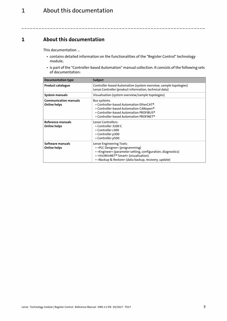
This documentation ...
• contains detailed information on the functionalities of the "Register Control" technology module;
• is part of the "Controller-based Automation" manual collection. It consists of the following sets of documentation:
Documentation type Subject
Product catalogue Controller-based Automation (system overview, sample topologies)Lenze Controller (product information, technical data)
System manuals Visualisation (system overview/sample topologies)
Communication manualsOnline helps
Bus systems• Controller-based Automation EtherCAT®• Controller-based Automation CANopen®• Controller-based Automation PROFIBUS®• Controller-based Automation PROFINET®
Reference manualsOnline helps
Lenze Controllers:• Controller 3200 C• Controller c300• Controller p300• Controller p500
Software manualsOnline helps
Lenze Engineering Tools:• »PLC Designer« (programming)• »Engineer« (parameter setting, configuration, diagnostics)• »VisiWinNET® Smart« (visualisation)• »Backup & Restore« (data backup, recovery, update)
1 About this documentation
4 Lenze · Technology module | Register Control · Reference Manual · DMS 3.3 EN · 05/2017 · TD17
_ _ _ _ _ _ _ _ _ _ _ _ _ _ _ _ _ _ _ _ _ _ _ _ _ _ _ _ _ _ _ _ _ _ _ _ _ _ _ _ _ _ _ _ _ _ _ _ _ _ _ _ _ _ _ _ _ _ _ _ _ _ _ _
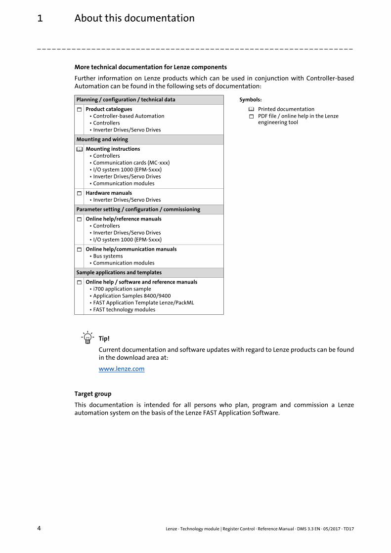
More technical documentation for Lenze components
Further information on Lenze products which can be used in conjunction with Controller-basedAutomation can be found in the following sets of documentation:
Tip!
Current documentation and software updates with regard to Lenze products can be foundin the download area at:
www.lenze.com
Target group
This documentation is intended for all persons who plan, program and commission a Lenzeautomation system on the basis of the Lenze FAST Application Software.
Planning / configuration / technical data Symbols:
Product catalogues• Controller-based Automation• Controllers• Inverter Drives/Servo Drives
Printed documentationPDF file / online help in the Lenze engineering tool
Mounting and wiring
Mounting instructions• Controllers• Communication cards (MC-xxx)• I/O system 1000 (EPM-Sxxx)• Inverter Drives/Servo Drives• Communication modules
Hardware manuals• Inverter Drives/Servo Drives
Parameter setting / configuration / commissioning
Online help/reference manuals• Controllers• Inverter Drives/Servo Drives• I/O system 1000 (EPM-Sxxx)
Online help/communication manuals• Bus systems• Communication modules
Sample applications and templates
Online help / software and reference manuals• i700 application sample• Application Samples 8400/9400• FAST Application Template Lenze/PackML• FAST technology modules
Lenze · Technology module | Register Control · Reference Manual · DMS 3.3 EN · 05/2017 · TD17 5
1 About this documentation1.1 Document history
_ _ _ _ _ _ _ _ _ _ _ _ _ _ _ _ _ _ _ _ _ _ _ _ _ _ _ _ _ _ _ _ _ _ _ _ _ _ _ _ _ _ _ _ _ _ _ _ _ _ _ _ _ _ _ _ _ _ _ _ _ _ _ _
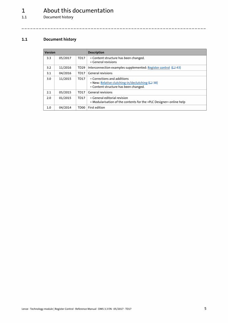
1.1 Document history
Version Description
3.3 05/2017 TD17 • Content structure has been changed.• General revisions
3.2 11/2016 TD29 Interconnection examples supplemented: Register control ( 43)
3.1 04/2016 TD17 General revisions
3.0 11/2015 TD17 • Corrections and additions• New: Relative clutching-in/declutching ( 38)• Content structure has been changed.
2.1 05/2015 TD17 General revisions
2.0 01/2015 TD17 • General editorial revision• Modularisation of the contents for the »PLC Designer« online help
1.0 04/2014 TD00 First edition
1 About this documentation1.2 Conventions used
6 Lenze · Technology module | Register Control · Reference Manual · DMS 3.3 EN · 05/2017 · TD17
_ _ _ _ _ _ _ _ _ _ _ _ _ _ _ _ _ _ _ _ _ _ _ _ _ _ _ _ _ _ _ _ _ _ _ _ _ _ _ _ _ _ _ _ _ _ _ _ _ _ _ _ _ _ _ _ _ _ _ _ _ _ _ _
1.2 Conventions used
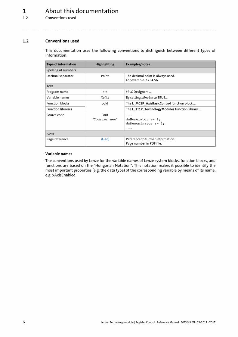
This documentation uses the following conventions to distinguish between different types ofinformation:
Variable names
The conventions used by Lenze for the variable names of Lenze system blocks, function blocks, andfunctions are based on the "Hungarian Notation". This notation makes it possible to identify themost important properties (e.g. the data type) of the corresponding variable by means of its name,e.g. xAxisEnabled.
Type of information Highlighting Examples/notes
Spelling of numbers
Decimal separator Point The decimal point is always used.For example: 1234.56
Text
Program name » « »PLC Designer« ...
Variable names italics By setting bEnable to TRUE...
Function blocks bold The L_MC1P_AxisBasicControl function block ...
Function libraries The L_TT1P_TechnologyModules function library ...
Source code Font"Courier new"
...dwNumerator := 1;dwDenominator := 1;...
Icons
Page reference ( 6) Reference to further information: Page number in PDF file.
Lenze · Technology module | Register Control · Reference Manual · DMS 3.3 EN · 05/2017 · TD17 7
1 About this documentation1.3 Definition of the notes used
_ _ _ _ _ _ _ _ _ _ _ _ _ _ _ _ _ _ _ _ _ _ _ _ _ _ _ _ _ _ _ _ _ _ _ _ _ _ _ _ _ _ _ _ _ _ _ _ _ _ _ _ _ _ _ _ _ _ _ _ _ _ _ _
1.3 Definition of the notes used
The following signal words and symbols are used in this documentation to indicate dangers andimportant information:
Safety instructions
Layout of the safety instructions:
Application notes
Pictograph and signal word!
(characterise the type and severity of danger)
Note
(describes the danger and gives information about how to prevent dangerous situations)
Pictograph Signal word Meaning
Danger! Danger of personal injury through dangerous electrical voltageReference to an imminent danger that may result in death or serious personal injury if the corresponding measures are not taken.
Danger! Danger of personal injury through a general source of dangerReference to an imminent danger that may result in death or serious personal injury if the corresponding measures are not taken.
Stop! Danger of property damageReference to a possible danger that may result in property damage if the corresponding measures are not taken.
Pictograph Signal word Meaning
Note! Important note to ensure trouble-free operation
Tip! Useful tip for easy handling
Reference to another document
2 Safety instructions
8 Lenze · Technology module | Register Control · Reference Manual · DMS 3.3 EN · 05/2017 · TD17
_ _ _ _ _ _ _ _ _ _ _ _ _ _ _ _ _ _ _ _ _ _ _ _ _ _ _ _ _ _ _ _ _ _ _ _ _ _ _ _ _ _ _ _ _ _ _ _ _ _ _ _ _ _ _ _ _ _ _ _ _ _ _ _
2 Safety instructions
Please observe the safety instructions in this documentation when you want to commission anautomation system or a plant with a Lenze Controller.
The device documentation contains safety instructions which must be observed!
Read the documentation supplied with the components of the automation system carefully before you start commissioning the Controller and the connected devices.
Danger!
High electrical voltage
Injury to persons caused by dangerous electrical voltage
Possible consequences
Death or severe injuries
Protective measures
Switch off the voltage supply before working on the components of the automation system.
After switching off the voltage supply, do not touch live device parts and power terminals immediately because capacitors may be charged.
Observe the corresponding information plates on the device.
Danger!
Injury to persons
Risk of injury is caused by ...• unpredictable motor movements (e.g. unintended direction of rotation, too high
velocities or jerky movement);• impermissible operating states during the parameterisation while there is an active
online connection to the device.
Possible consequences
Death or severe injuries
Protective measures• If required, provide systems with installed inverters with additional monitoring and
protective devices according to the safety regulations valid in each case (e.g. law on technical equipment, regulations for the prevention of accidents).
• During commissioning, maintain an adequate safety distance to the motor or the machine parts driven by the motor.
Lenze · Technology module | Register Control · Reference Manual · DMS 3.3 EN · 05/2017 · TD17 9
2 Safety instructions
_ _ _ _ _ _ _ _ _ _ _ _ _ _ _ _ _ _ _ _ _ _ _ _ _ _ _ _ _ _ _ _ _ _ _ _ _ _ _ _ _ _ _ _ _ _ _ _ _ _ _ _ _ _ _ _ _ _ _ _ _ _ _ _
Stop!
Damage or destruction of machine parts
Damage or destruction of machine parts can be caused by ...• Short circuit or static discharges (ESD);• unpredictable motor movements (e.g. unintended direction of rotation, too high
velocities or jerky movement);• impermissible operating states during the parameterisation while there is an active
online connection to the device.
Protective measures• Always switch off the voltage supply before working on the components of the
automation system.• Do not touch electronic components and contacts unless ESD measures were taken
beforehand.• If required, provide systems with installed inverters with additional monitoring and
protective devices according to the safety regulations valid in each case (e.g. law on technical equipment, regulations for the prevention of accidents).
3 Functional description of "Register Control"
10 Lenze · Technology module | Register Control · Reference Manual · DMS 3.3 EN · 05/2017 · TD17
_ _ _ _ _ _ _ _ _ _ _ _ _ _ _ _ _ _ _ _ _ _ _ _ _ _ _ _ _ _ _ _ _ _ _ _ _ _ _ _ _ _ _ _ _ _ _ _ _ _ _ _ _ _ _ _ _ _ _ _ _ _ _ _
3 Functional description of "Register Control"
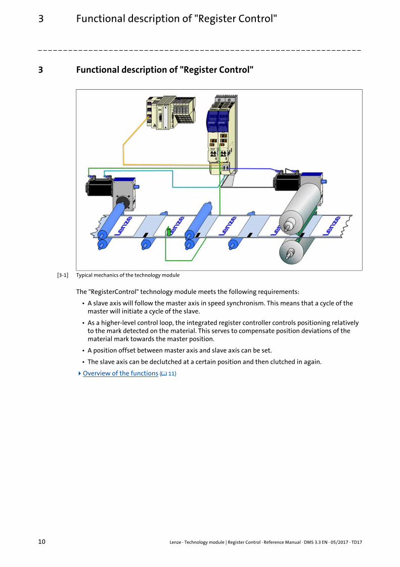
[3-1] Typical mechanics of the technology module
The "RegisterControl" technology module meets the following requirements:
• A slave axis will follow the master axis in speed synchronism. This means that a cycle of the master will initiate a cycle of the slave.
• As a higher-level control loop, the integrated register controller controls positioning relatively to the mark detected on the material. This serves to compensate position deviations of the material mark towards the master position.
• A position offset between master axis and slave axis can be set.
• The slave axis can be declutched at a certain position and then clutched in again.
Overview of the functions ( 11)
Lenze · Technology module | Register Control · Reference Manual · DMS 3.3 EN · 05/2017 · TD17 11
3 Functional description of "Register Control"3.1 Overview of the functions
_ _ _ _ _ _ _ _ _ _ _ _ _ _ _ _ _ _ _ _ _ _ _ _ _ _ _ _ _ _ _ _ _ _ _ _ _ _ _ _ _ _ _ _ _ _ _ _ _ _ _ _ _ _ _ _ _ _ _ _ _ _ _ _
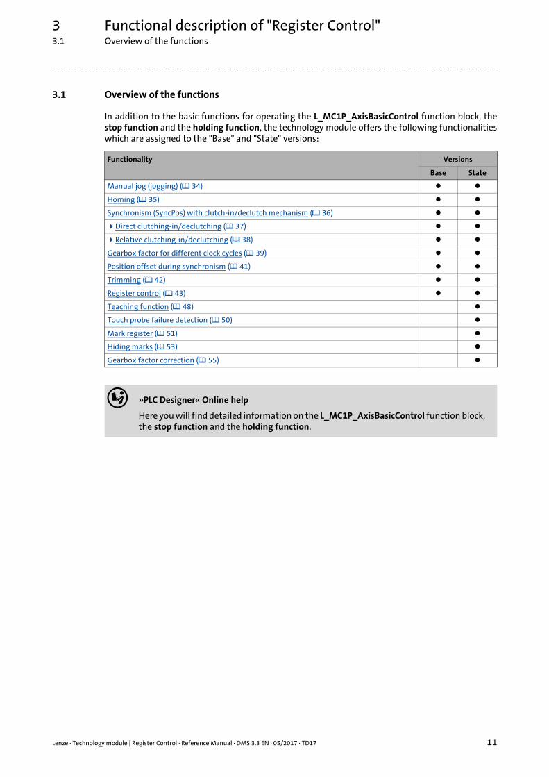
3.1 Overview of the functions
In addition to the basic functions for operating the L_MC1P_AxisBasicControl function block, thestop function and the holding function, the technology module offers the following functionalitieswhich are assigned to the "Base" and "State" versions:
Functionality Versions
Base State
Manual jog (jogging) ( 34)
Homing ( 35)
Synchronism (SyncPos) with clutch-in/declutch mechanism ( 36)
Direct clutching-in/declutching ( 37)
Relative clutching-in/declutching ( 38)
Gearbox factor for different clock cycles ( 39)
Position offset during synchronism ( 41)
Trimming ( 42)
Register control ( 43)
Teaching function ( 48)
Touch probe failure detection ( 50)
Mark register ( 51)
Hiding marks ( 53)
Gearbox factor correction ( 55)
»PLC Designer« Online help
Here you will find detailed information on the L_MC1P_AxisBasicControl function block, the stop function and the holding function.
3 Functional description of "Register Control"3.2 Important notes on how to operate the technology module
12 Lenze · Technology module | Register Control · Reference Manual · DMS 3.3 EN · 05/2017 · TD17
_ _ _ _ _ _ _ _ _ _ _ _ _ _ _ _ _ _ _ _ _ _ _ _ _ _ _ _ _ _ _ _ _ _ _ _ _ _ _ _ _ _ _ _ _ _ _ _ _ _ _ _ _ _ _ _ _ _ _ _ _ _ _ _
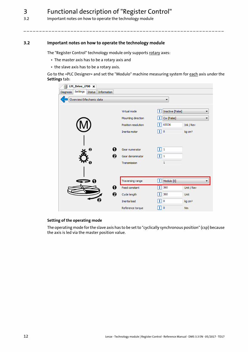
3.2 Important notes on how to operate the technology module
The "Register Control" technology module only supports rotary axes:
• The master axis has to be a rotary axis and
• the slave axis has to be a rotary axis.
Go to the »PLC Designer« and set the "Modulo" machine measuring system for each axis under theSettings tab:
Setting of the operating mode
The operating mode for the slave axis has to be set to "cyclically synchronous position" (csp) becausethe axis is led via the master position value.
Lenze · Technology module | Register Control · Reference Manual · DMS 3.3 EN · 05/2017 · TD17 13
3 Functional description of "Register Control"3.2 Important notes on how to operate the technology module
_ _ _ _ _ _ _ _ _ _ _ _ _ _ _ _ _ _ _ _ _ _ _ _ _ _ _ _ _ _ _ _ _ _ _ _ _ _ _ _ _ _ _ _ _ _ _ _ _ _ _ _ _ _ _ _ _ _ _ _ _ _ _ _
Controlled start of the axes
Motion commands that are set in the inhibited axis state (xAxisEnabled = FALSE) after enable(xRegulatorOn = TRUE) must be activated again by a FALSETRUE edge.
In this way it is prevented that the drive starts in an uncontrolled manner after controller enable.
Example Manual jog (jogging) ( 34):
1. In the inhibited axis state (xAxisEnabled = FALSE), xJogPos is set to TRUE.• xRegulatorOn = FALSE (axis is inhibited.)
==> "READY" state (xAxisEnabled = FALSE)• xJogPos = TRUE (manual jog is to be executed.)
2. Enable axis.• xRegulatorOn = TRUE
==> "READY" state (xAxisEnabled = TRUE)
3. Execute manual jog.• xJogPos = FALSETRUE
==> "JOGPOS" state
3 Functional description of "Register Control"3.3 Function block L_TT1P_RegisterControl[Base/State]
14 Lenze · Technology module | Register Control · Reference Manual · DMS 3.3 EN · 05/2017 · TD17
_ _ _ _ _ _ _ _ _ _ _ _ _ _ _ _ _ _ _ _ _ _ _ _ _ _ _ _ _ _ _ _ _ _ _ _ _ _ _ _ _ _ _ _ _ _ _ _ _ _ _ _ _ _ _ _ _ _ _ _ _ _ _ _
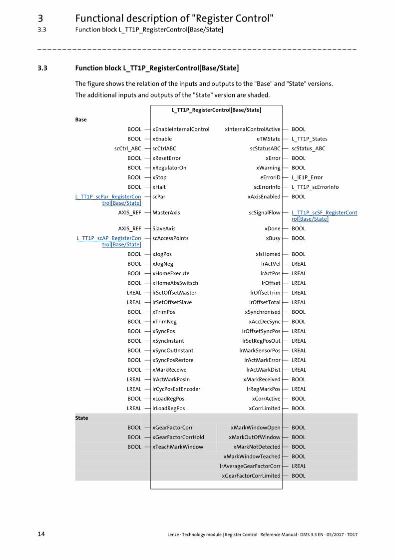
3.3 Function block L_TT1P_RegisterControl[Base/State]
The figure shows the relation of the inputs and outputs to the "Base" and "State" versions.
The additional inputs and outputs of the "State" version are shaded.
L_TT1P_RegisterControl[Base/State]
Base
BOOL xEnableInternalControl xInternalControlActive BOOL
BOOL xEnable eTMState L_TT1P_States
scCtrl_ABC scCtrlABC scStatusABC scStatus_ABC
BOOL xResetError xError BOOL
BOOL xRegulatorOn xWarning BOOL
BOOL xStop eErrorID L_IE1P_Error
BOOL xHalt scErrorInfo L_TT1P_scErrorInfo
L_TT1P_scPar_RegisterControl[Base/State]
scPar xAxisEnabled BOOL
AXIS_REF MasterAxis scSignalFlow L_TT1P_scSF_RegisterControl[Base/State]
AXIS_REF SlaveAxis xDone BOOL
L_TT1P_scAP_RegisterControl[Base/State]
scAccessPoints xBusy BOOL
BOOL xJogPos xIsHomed BOOL
BOOL xJogNeg lrActVel LREAL
BOOL xHomeExecute lrActPos LREAL
BOOL xHomeAbsSwitsch lrOffset LREAL
LREAL lrSetOffsetMaster lrOffsetTrim LREAL
LREAL lrSetOffsetSlave lrOffsetTotal LREAL
BOOL xTrimPos xSynchronised BOOL
BOOL xTrimNeg xAccDecSync BOOL
BOOL xSyncPos lrOffsetSyncPos LREAL
BOOL xSyncInstant lrSetRegPosOut LREAL
BOOL xSyncOutInstant lrMarkSensorPos LREAL
BOOL xSyncPosRestore lrActMarkError LREAL
BOOL xMarkReceive lrActMarkDist LREAL
LREAL lrActMarkPosIn xMarkReceived BOOL
LREAL lrCycPosExtEncoder lrRegMarkPos LREAL
BOOL xLoadRegPos xCorrActive BOOL
LREAL lrLoadRegPos xCorrLimited BOOL
State
BOOL xGearFactorCorr xMarkWindowOpen BOOL
BOOL xGearFactorCorrHold xMarkOutOfWindow BOOL
BOOL xTeachMarkWindow xMarkNotDetected BOOL
xMarkWindowTeached BOOL
lrAverageGearFactorCorr LREAL
xGearFactorCorrLimited BOOL
Lenze · Technology module | Register Control · Reference Manual · DMS 3.3 EN · 05/2017 · TD17 15
3 Functional description of "Register Control"3.3 Function block L_TT1P_RegisterControl[Base/State]
_ _ _ _ _ _ _ _ _ _ _ _ _ _ _ _ _ _ _ _ _ _ _ _ _ _ _ _ _ _ _ _ _ _ _ _ _ _ _ _ _ _ _ _ _ _ _ _ _ _ _ _ _ _ _ _ _ _ _ _ _ _ _ _
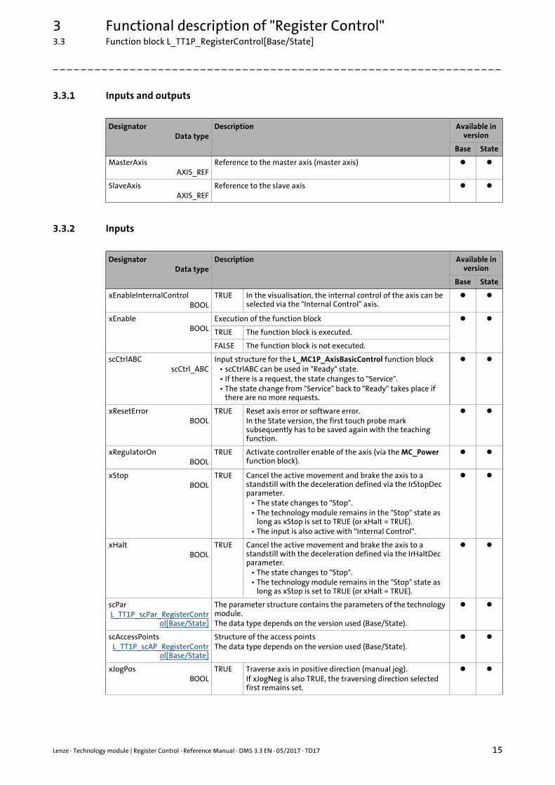
3.3.1 Inputs and outputs
3.3.2 Inputs
DesignatorData type
Description Available in version
Base State
MasterAxisAXIS_REF
Reference to the master axis (master axis)
SlaveAxisAXIS_REF
Reference to the slave axis
DesignatorData type
Description Available in version
Base State
xEnableInternalControlBOOL
TRUE In the visualisation, the internal control of the axis can be selected via the "Internal Control" axis.
xEnableBOOL
Execution of the function block
TRUE The function block is executed.
FALSE The function block is not executed.
scCtrlABCscCtrl_ABC
Input structure for the L_MC1P_AxisBasicControl function block• scCtrlABC can be used in "Ready" state.• If there is a request, the state changes to "Service".• The state change from "Service" back to "Ready" takes place if
there are no more requests.
xResetErrorBOOL
TRUE Reset axis error or software error.In the State version, the first touch probe mark subsequently has to be saved again with the teaching function.
xRegulatorOnBOOL
TRUE Activate controller enable of the axis (via the MC_Power function block).
xStopBOOL
TRUE Cancel the active movement and brake the axis to a standstill with the deceleration defined via the IrStopDec parameter.
• The state changes to "Stop".• The technology module remains in the "Stop" state as
long as xStop is set to TRUE (or xHalt = TRUE).• The input is also active with "Internal Control".
xHaltBOOL
TRUE Cancel the active movement and brake the axis to a standstill with the deceleration defined via the IrHaltDec parameter.
• The state changes to "Stop".• The technology module remains in the "Stop" state as
long as xStop is set to TRUE (or xHalt = TRUE).
scParL_TT1P_scPar_RegisterContr
ol[Base/State]
The parameter structure contains the parameters of the technology module.The data type depends on the version used (Base/State).
scAccessPointsL_TT1P_scAP_RegisterContr
ol[Base/State]
Structure of the access pointsThe data type depends on the version used (Base/State).
xJogPosBOOL
TRUE Traverse axis in positive direction (manual jog).If xJogNeg is also TRUE, the traversing direction selected first remains set.
3 Functional description of "Register Control"3.3 Function block L_TT1P_RegisterControl[Base/State]
16 Lenze · Technology module | Register Control · Reference Manual · DMS 3.3 EN · 05/2017 · TD17
_ _ _ _ _ _ _ _ _ _ _ _ _ _ _ _ _ _ _ _ _ _ _ _ _ _ _ _ _ _ _ _ _ _ _ _ _ _ _ _ _ _ _ _ _ _ _ _ _ _ _ _ _ _ _ _ _ _ _ _ _ _ _ _
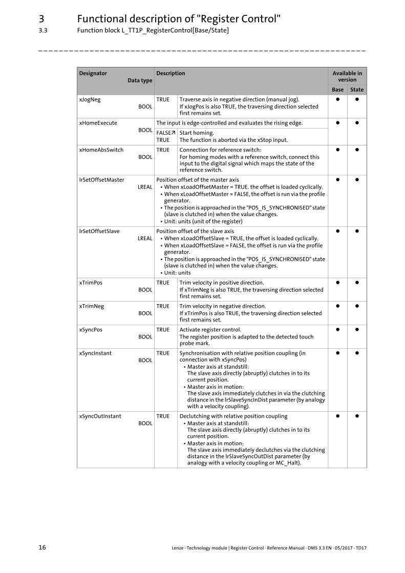
xJogNegBOOL
TRUE Traverse axis in negative direction (manual jog).If xJogPos is also TRUE, the traversing direction selected first remains set.
xHomeExecuteBOOL
The input is edge-controlled and evaluates the rising edge.
FALSETRUE
Start homing.The function is aborted via the xStop input.
xHomeAbsSwitchBOOL
TRUE Connection for reference switch:For homing modes with a reference switch, connect this input to the digital signal which maps the state of the reference switch.
lrSetOffsetMasterLREAL
Position offset of the master axis• When xLoadOffsetMaster = TRUE. the offset is loaded cyclically.• When xLoadOffsetMaster = FALSE, the offset is run via the profile
generator.• The position is approached in the "POS_IS_SYNCHRONISED" state
(slave is clutched in) when the value changes.• Unit: units (unit of the register)
lrSetOffsetSlaveLREAL
Position offset of the slave axis• When xLoadOffsetSlave = TRUE, the offset is loaded cyclically.• When xLoadOffsetSlave = FALSE, the offset is run via the profile
generator.• The position is approached in the "POS_IS_SYNCHRONISED" state
(slave is clutched in) when the value changes.• Unit: units
xTrimPosBOOL
TRUE Trim velocity in positive direction.If xTrimNeg is also TRUE, the traversing direction selected first remains set.
xTrimNegBOOL
TRUE Trim velocity in negative direction.If xTrimPos is also TRUE, the traversing direction selected first remains set.
xSyncPosBOOL
TRUE Activate register control.The register position is adapted to the detected touch probe mark.
xSyncInstantBOOL
TRUE Synchronisation with relative position coupling (in connection with xSyncPos)
• Master axis at standstill:The slave axis directly (abruptly) clutches in to its current position.
• Master axis in motion:The slave axis immediately clutches in via the clutching distance in the lrSlaveSyncInDist parameter (by analogy with a velocity coupling).
xSyncOutInstantBOOL
TRUE Declutching with relative position coupling• Master axis at standstill:
The slave axis directly (abruptly) clutches in to its current position.
• Master axis in motion:The slave axis immediately declutches via the clutching distance in the lrSlaveSyncOutDist parameter (by analogy with a velocity coupling or MC_Halt).
DesignatorData type
Description Available in version
Base State
Lenze · Technology module | Register Control · Reference Manual · DMS 3.3 EN · 05/2017 · TD17 17
3 Functional description of "Register Control"3.3 Function block L_TT1P_RegisterControl[Base/State]
_ _ _ _ _ _ _ _ _ _ _ _ _ _ _ _ _ _ _ _ _ _ _ _ _ _ _ _ _ _ _ _ _ _ _ _ _ _ _ _ _ _ _ _ _ _ _ _ _ _ _ _ _ _ _ _ _ _ _ _ _ _ _ _
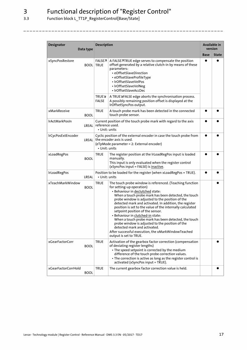
xSyncPosRestoreBOOL
FALSETRUE
A FALSETRUE edge serves to compensate the position offset generated by a relative clutch-in by means of these parameters:
• eOffsetSlaveDirection• eOffsetSlaveProfileType• lrOffsetSlaveVelPos• lrOffsetSlaveVelNeg• lrOffsetSlaveAccDec
TRUEFALSE
A TRUEFALSE edge aborts the synchronisation process.A possibly remaining position offset is displayed at the lrOffsetSyncPos output.
xMarkReceiveBOOL
TRUE A touch probe mark has been detected in the connected touch probe sensor.
lrActMarkPosInLREAL
Current position of the touch probe mark with regard to the axis reference used.
• Unit: units
lrCycPosExtEncoderLREAL
Cyclic position of the external encoder in case the touch probe from the encoder axis is used.(eTpMode parameter = 2: External encoder)
• Unit: units
xLoadRegPosBOOL
TRUE The register position at the lrLoadRegPos input is loaded manually.This input is only evaluated when the register control (xSyncPos input = FALSE) is inactive.
lrLoadRegPosLREAL
Position to be loaded for the register (when xLoadRegPos = TRUE).• Unit: units
xTeachMarkWindowBOOL
TRUE The touch probe window is referenced. (Teaching function for setting-up operation)
• Behaviour in declutched state:When a touch probe mark has been detected, the touch probe window is adjusted to the position of the detected mark and activated. In addition, the register position is set to the value of the internally calculated setpoint position of the sensor.
• Behaviour in clutched-in state:When a touch probe mark has been detected, the touch probe window is adjusted to the position of the detected mark and activated.
After successful execution, the xMarkWindowTeached output is set to TRUE.
xGearFactorCorrBOOL
TRUE Activation of the gearbox factor correction (compensation of deviating register lengths)
• The speed setpoint is corrected by the medium difference of the touch probe correction values.
• The correction is active as long as the register control is activated (xSyncPos input = TRUE).
xGearFactorCorrHoldBOOL
TRUE The current gearbox factor correction value is held.
DesignatorData type
Description Available in version
Base State
3 Functional description of "Register Control"3.3 Function block L_TT1P_RegisterControl[Base/State]
18 Lenze · Technology module | Register Control · Reference Manual · DMS 3.3 EN · 05/2017 · TD17
_ _ _ _ _ _ _ _ _ _ _ _ _ _ _ _ _ _ _ _ _ _ _ _ _ _ _ _ _ _ _ _ _ _ _ _ _ _ _ _ _ _ _ _ _ _ _ _ _ _ _ _ _ _ _ _ _ _ _ _ _ _ _ _
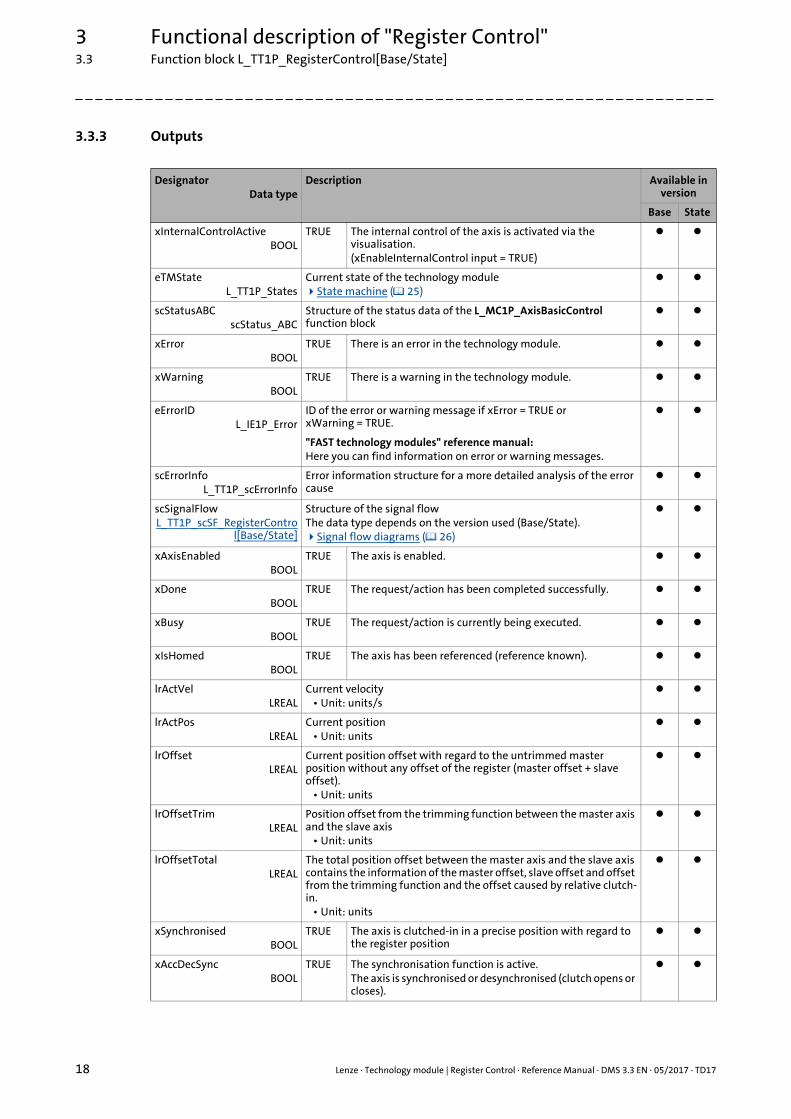
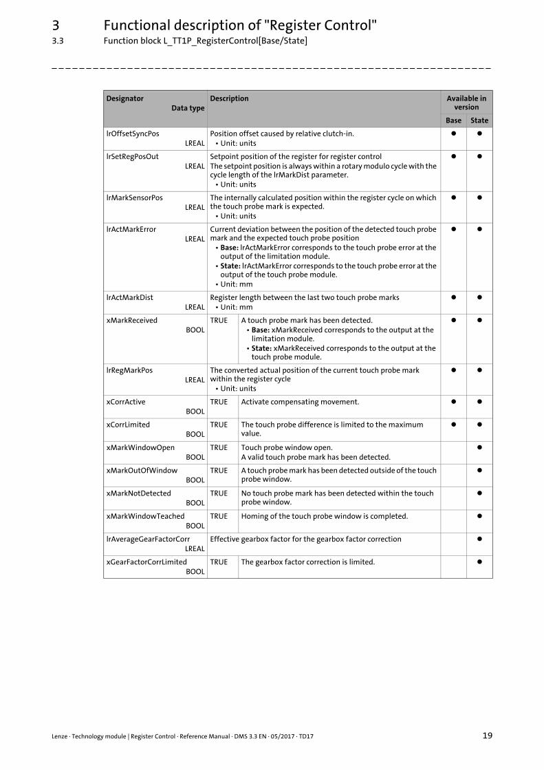
3.3.3 Outputs
DesignatorData type
Description Available in version
Base State
xInternalControlActiveBOOL
TRUE The internal control of the axis is activated via the visualisation.(xEnableInternalControl input = TRUE)
eTMStateL_TT1P_States
Current state of the technology moduleState machine ( 25)
scStatusABCscStatus_ABC
Structure of the status data of the L_MC1P_AxisBasicControl function block
xErrorBOOL
TRUE There is an error in the technology module.
xWarningBOOL
TRUE There is a warning in the technology module.
eErrorIDL_IE1P_Error
ID of the error or warning message if xError = TRUE or xWarning = TRUE.
"FAST technology modules" reference manual:Here you can find information on error or warning messages.
scErrorInfoL_TT1P_scErrorInfo
Error information structure for a more detailed analysis of the error cause
scSignalFlowL_TT1P_scSF_RegisterContro
l[Base/State]
Structure of the signal flowThe data type depends on the version used (Base/State).Signal flow diagrams ( 26)
xAxisEnabledBOOL
TRUE The axis is enabled.
xDoneBOOL
TRUE The request/action has been completed successfully.
xBusyBOOL
TRUE The request/action is currently being executed.
xIsHomedBOOL
TRUE The axis has been referenced (reference known).
lrActVelLREAL
Current velocity• Unit: units/s
lrActPosLREAL
Current position• Unit: units
lrOffsetLREAL
Current position offset with regard to the untrimmed master position without any offset of the register (master offset + slave offset).
• Unit: units
lrOffsetTrimLREAL
Position offset from the trimming function between the master axis and the slave axis
• Unit: units
lrOffsetTotalLREAL
The total position offset between the master axis and the slave axis contains the information of the master offset, slave offset and offset from the trimming function and the offset caused by relative clutch-in.
• Unit: units
xSynchronisedBOOL
TRUE The axis is clutched-in in a precise position with regard to the register position
xAccDecSyncBOOL
TRUE The synchronisation function is active.The axis is synchronised or desynchronised (clutch opens or closes).
Lenze · Technology module | Register Control · Reference Manual · DMS 3.3 EN · 05/2017 · TD17 19
3 Functional description of "Register Control"3.3 Function block L_TT1P_RegisterControl[Base/State]
_ _ _ _ _ _ _ _ _ _ _ _ _ _ _ _ _ _ _ _ _ _ _ _ _ _ _ _ _ _ _ _ _ _ _ _ _ _ _ _ _ _ _ _ _ _ _ _ _ _ _ _ _ _ _ _ _ _ _ _ _ _ _ _
lrOffsetSyncPosLREAL
Position offset caused by relative clutch-in.• Unit: units
lrSetRegPosOutLREAL
Setpoint position of the register for register controlThe setpoint position is always within a rotary modulo cycle with the cycle length of the lrMarkDist parameter.
• Unit: units
lrMarkSensorPosLREAL
The internally calculated position within the register cycle on which the touch probe mark is expected.
• Unit: units
lrActMarkErrorLREAL
Current deviation between the position of the detected touch probe mark and the expected touch probe position
• Base: lrActMarkError corresponds to the touch probe error at the output of the limitation module.
• State: lrActMarkError corresponds to the touch probe error at the output of the touch probe module.
• Unit: mm
lrActMarkDistLREAL
Register length between the last two touch probe marks• Unit: mm
xMarkReceivedBOOL
TRUE A touch probe mark has been detected.• Base: xMarkReceived corresponds to the output at the
limitation module.• State: xMarkReceived corresponds to the output at the
touch probe module.
lrRegMarkPosLREAL
The converted actual position of the current touch probe mark within the register cycle
• Unit: units
xCorrActiveBOOL
TRUE Activate compensating movement.
xCorrLimitedBOOL
TRUE The touch probe difference is limited to the maximum value.
xMarkWindowOpenBOOL
TRUE Touch probe window open.A valid touch probe mark has been detected.
xMarkOutOfWindowBOOL
TRUE A touch probe mark has been detected outside of the touch probe window.
xMarkNotDetectedBOOL
TRUE No touch probe mark has been detected within the touch probe window.
xMarkWindowTeachedBOOL
TRUE Homing of the touch probe window is completed.
lrAverageGearFactorCorrLREAL
Effective gearbox factor for the gearbox factor correction
xGearFactorCorrLimitedBOOL
TRUE The gearbox factor correction is limited.
DesignatorData type
Description Available in version
Base State
3 Functional description of "Register Control"3.3 Function block L_TT1P_RegisterControl[Base/State]
20 Lenze · Technology module | Register Control · Reference Manual · DMS 3.3 EN · 05/2017 · TD17
_ _ _ _ _ _ _ _ _ _ _ _ _ _ _ _ _ _ _ _ _ _ _ _ _ _ _ _ _ _ _ _ _ _ _ _ _ _ _ _ _ _ _ _ _ _ _ _ _ _ _ _ _ _ _ _ _ _ _ _ _ _ _ _
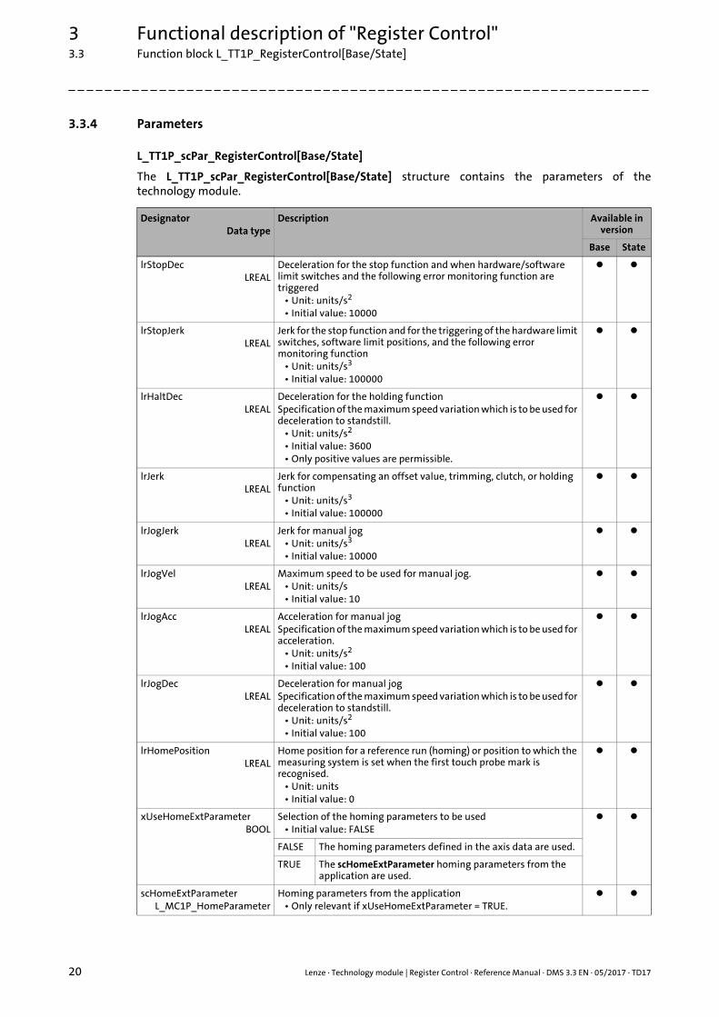
3.3.4 Parameters
L_TT1P_scPar_RegisterControl[Base/State]
The L_TT1P_scPar_RegisterControl[Base/State] structure contains the parameters of thetechnology module.
DesignatorData type
Description Available in version
Base State
lrStopDecLREAL
Deceleration for the stop function and when hardware/software limit switches and the following error monitoring function are triggered
• Unit: units/s2
• Initial value: 10000
lrStopJerkLREAL
Jerk for the stop function and for the triggering of the hardware limit switches, software limit positions, and the following error monitoring function
• Unit: units/s3
• Initial value: 100000
lrHaltDecLREAL
Deceleration for the holding functionSpecification of the maximum speed variation which is to be used for deceleration to standstill.
• Unit: units/s2
• Initial value: 3600• Only positive values are permissible.
lrJerkLREAL
Jerk for compensating an offset value, trimming, clutch, or holding function
• Unit: units/s3
• Initial value: 100000
lrJogJerkLREAL
Jerk for manual jog• Unit: units/s3
• Initial value: 10000
lrJogVelLREAL
Maximum speed to be used for manual jog.• Unit: units/s• Initial value: 10
lrJogAccLREAL
Acceleration for manual jogSpecification of the maximum speed variation which is to be used for acceleration.
• Unit: units/s2
• Initial value: 100
lrJogDecLREAL
Deceleration for manual jogSpecification of the maximum speed variation which is to be used for deceleration to standstill.
• Unit: units/s2
• Initial value: 100
lrHomePositionLREAL
Home position for a reference run (homing) or position to which the measuring system is set when the first touch probe mark is recognised.
• Unit: units• Initial value: 0
xUseHomeExtParameterBOOL
Selection of the homing parameters to be used• Initial value: FALSE
FALSE The homing parameters defined in the axis data are used.
TRUE The scHomeExtParameter homing parameters from the application are used.
scHomeExtParameterL_MC1P_HomeParameter
Homing parameters from the application• Only relevant if xUseHomeExtParameter = TRUE.
Lenze · Technology module | Register Control · Reference Manual · DMS 3.3 EN · 05/2017 · TD17 21
3 Functional description of "Register Control"3.3 Function block L_TT1P_RegisterControl[Base/State]
_ _ _ _ _ _ _ _ _ _ _ _ _ _ _ _ _ _ _ _ _ _ _ _ _ _ _ _ _ _ _ _ _ _ _ _ _ _ _ _ _ _ _ _ _ _ _ _ _ _ _ _ _ _ _ _ _ _ _ _ _ _ _ _
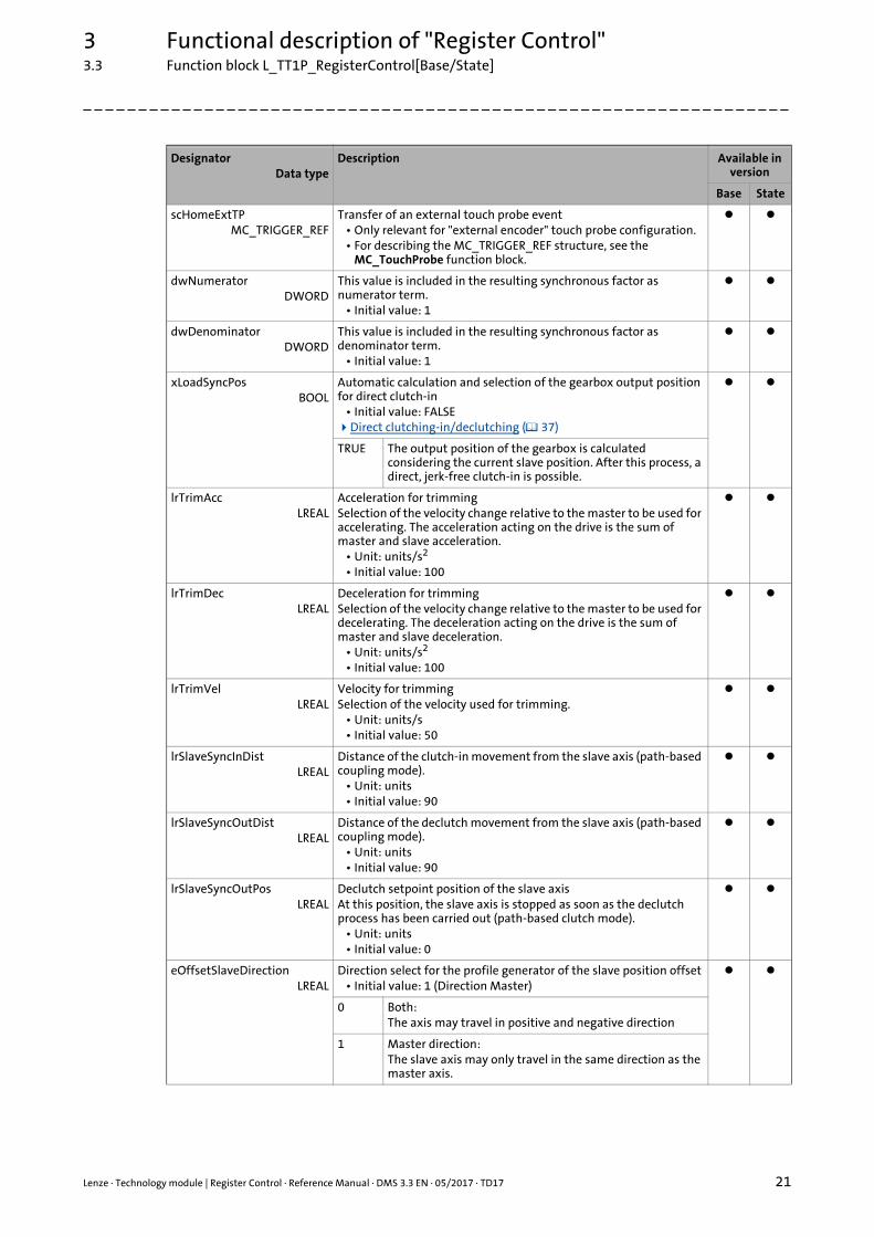
scHomeExtTPMC_TRIGGER_REF
Transfer of an external touch probe event• Only relevant for "external encoder" touch probe configuration.• For describing the MC_TRIGGER_REF structure, see the
MC_TouchProbe function block.
dwNumerator DWORD
This value is included in the resulting synchronous factor as numerator term.
• Initial value: 1
dwDenominatorDWORD
This value is included in the resulting synchronous factor as denominator term.
• Initial value: 1
xLoadSyncPosBOOL
Automatic calculation and selection of the gearbox output position for direct clutch-in
• Initial value: FALSEDirect clutching-in/declutching ( 37)
TRUE The output position of the gearbox is calculated considering the current slave position. After this process, a direct, jerk-free clutch-in is possible.
lrTrimAccLREAL
Acceleration for trimmingSelection of the velocity change relative to the master to be used for accelerating. The acceleration acting on the drive is the sum of master and slave acceleration.
• Unit: units/s2
• Initial value: 100
lrTrimDecLREAL
Deceleration for trimmingSelection of the velocity change relative to the master to be used for decelerating. The deceleration acting on the drive is the sum of master and slave deceleration.
• Unit: units/s2
• Initial value: 100
lrTrimVelLREAL
Velocity for trimmingSelection of the velocity used for trimming.
• Unit: units/s• Initial value: 50
lrSlaveSyncInDistLREAL
Distance of the clutch-in movement from the slave axis (path-based coupling mode).
• Unit: units• Initial value: 90
lrSlaveSyncOutDistLREAL
Distance of the declutch movement from the slave axis (path-based coupling mode).
• Unit: units• Initial value: 90
lrSlaveSyncOutPosLREAL
Declutch setpoint position of the slave axisAt this position, the slave axis is stopped as soon as the declutch process has been carried out (path-based clutch mode).
• Unit: units• Initial value: 0
eOffsetSlaveDirectionLREAL
Direction select for the profile generator of the slave position offset• Initial value: 1 (Direction Master)
0 Both:The axis may travel in positive and negative direction
1 Master direction:The slave axis may only travel in the same direction as the master axis.
DesignatorData type
Description Available in version
Base State
3 Functional description of "Register Control"3.3 Function block L_TT1P_RegisterControl[Base/State]
22 Lenze · Technology module | Register Control · Reference Manual · DMS 3.3 EN · 05/2017 · TD17
_ _ _ _ _ _ _ _ _ _ _ _ _ _ _ _ _ _ _ _ _ _ _ _ _ _ _ _ _ _ _ _ _ _ _ _ _ _ _ _ _ _ _ _ _ _ _ _ _ _ _ _ _ _ _ _ _ _ _ _ _ _ _ _
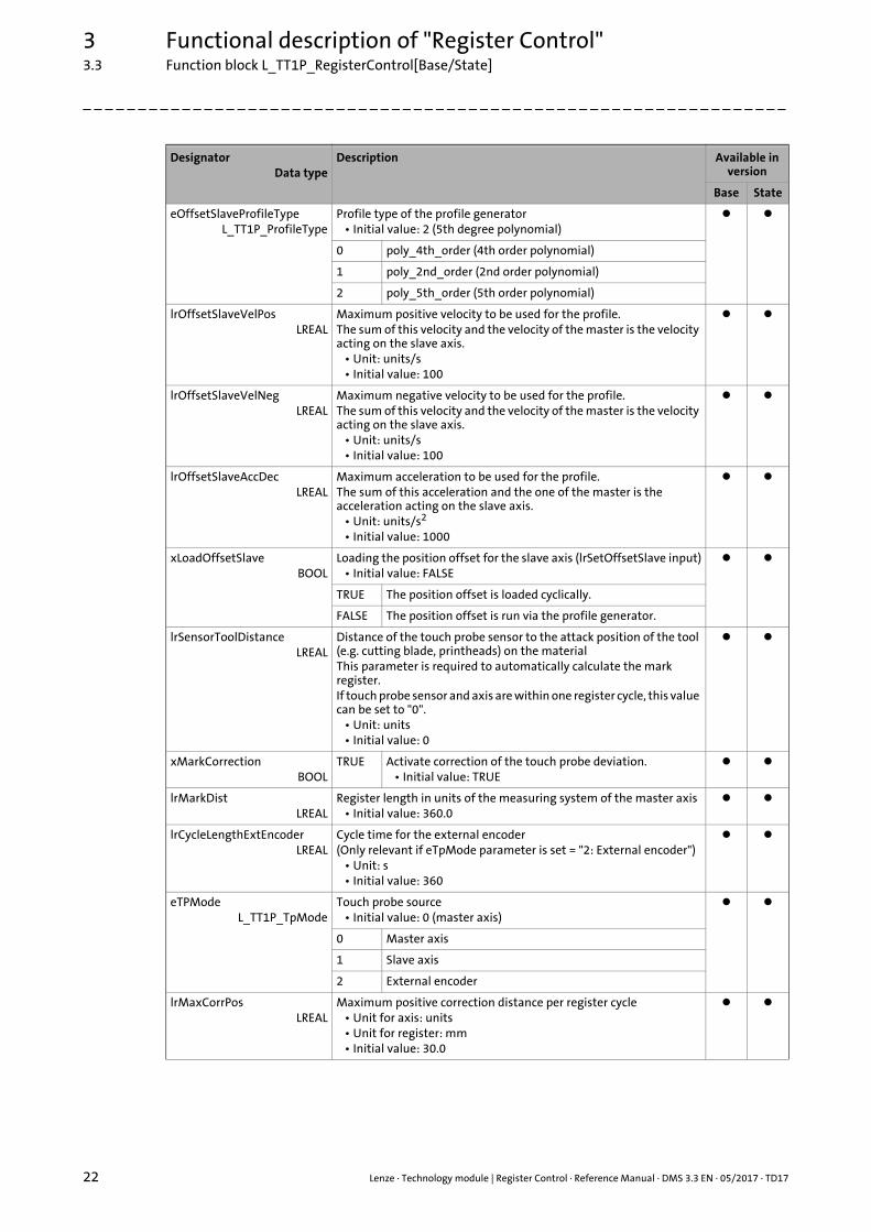
eOffsetSlaveProfileTypeL_TT1P_ProfileType
Profile type of the profile generator• Initial value: 2 (5th degree polynomial)
0 poly_4th_order (4th order polynomial)
1 poly_2nd_order (2nd order polynomial)
2 poly_5th_order (5th order polynomial)
lrOffsetSlaveVelPosLREAL
Maximum positive velocity to be used for the profile.The sum of this velocity and the velocity of the master is the velocity acting on the slave axis.
• Unit: units/s• Initial value: 100
lrOffsetSlaveVelNegLREAL
Maximum negative velocity to be used for the profile.The sum of this velocity and the velocity of the master is the velocity acting on the slave axis.
• Unit: units/s• Initial value: 100
lrOffsetSlaveAccDecLREAL
Maximum acceleration to be used for the profile.The sum of this acceleration and the one of the master is the acceleration acting on the slave axis.
• Unit: units/s2
• Initial value: 1000
xLoadOffsetSlaveBOOL
Loading the position offset for the slave axis (lrSetOffsetSlave input)• Initial value: FALSE
TRUE The position offset is loaded cyclically.
FALSE The position offset is run via the profile generator.
lrSensorToolDistanceLREAL
Distance of the touch probe sensor to the attack position of the tool (e.g. cutting blade, printheads) on the materialThis parameter is required to automatically calculate the mark register.If touch probe sensor and axis are within one register cycle, this value can be set to "0".
• Unit: units• Initial value: 0
xMarkCorrection BOOL
TRUE Activate correction of the touch probe deviation.• Initial value: TRUE
lrMarkDistLREAL
Register length in units of the measuring system of the master axis• Initial value: 360.0
lrCycleLengthExtEncoderLREAL
Cycle time for the external encoder(Only relevant if eTpMode parameter is set = "2: External encoder")
• Unit: s• Initial value: 360
eTPModeL_TT1P_TpMode
Touch probe source• Initial value: 0 (master axis)
0 Master axis
1 Slave axis
2 External encoder
lrMaxCorrPosLREAL
Maximum positive correction distance per register cycle• Unit for axis: units• Unit for register: mm• Initial value: 30.0
DesignatorData type
Description Available in version
Base State
Lenze · Technology module | Register Control · Reference Manual · DMS 3.3 EN · 05/2017 · TD17 23
3 Functional description of "Register Control"3.3 Function block L_TT1P_RegisterControl[Base/State]
_ _ _ _ _ _ _ _ _ _ _ _ _ _ _ _ _ _ _ _ _ _ _ _ _ _ _ _ _ _ _ _ _ _ _ _ _ _ _ _ _ _ _ _ _ _ _ _ _ _ _ _ _ _ _ _ _ _ _ _ _ _ _ _
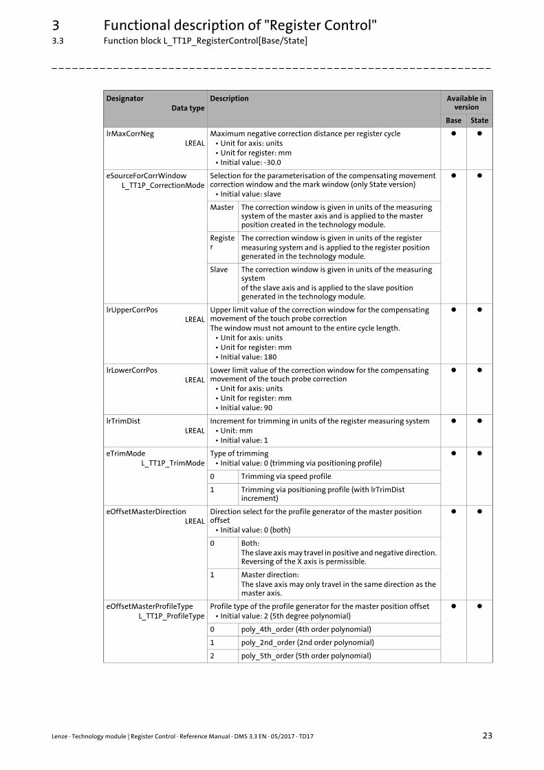
lrMaxCorrNegLREAL
Maximum negative correction distance per register cycle• Unit for axis: units• Unit for register: mm• Initial value: -30.0
eSourceForCorrWindowL_TT1P_CorrectionMode
Selection for the parameterisation of the compensating movement correction window and the mark window (only State version)
• Initial value: slave
Master The correction window is given in units of the measuring system of the master axis and is applied to the master position created in the technology module.
Register
The correction window is given in units of the registermeasuring system and is applied to the register position generated in the technology module.
Slave The correction window is given in units of the measuring systemof the slave axis and is applied to the slave position generated in the technology module.
lrUpperCorrPosLREAL
Upper limit value of the correction window for the compensating movement of the touch probe correctionThe window must not amount to the entire cycle length.
• Unit for axis: units• Unit for register: mm• Initial value: 180
lrLowerCorrPosLREAL
Lower limit value of the correction window for the compensating movement of the touch probe correction
• Unit for axis: units• Unit for register: mm• Initial value: 90
lrTrimDistLREAL
Increment for trimming in units of the register measuring system• Unit: mm• Initial value: 1
eTrimModeL_TT1P_TrimMode
Type of trimming• Initial value: 0 (trimming via positioning profile)
0 Trimming via speed profile
1 Trimming via positioning profile (with lrTrimDist increment)
eOffsetMasterDirectionLREAL
Direction select for the profile generator of the master position offset
• Initial value: 0 (both)
0 Both:The slave axis may travel in positive and negative direction. Reversing of the X axis is permissible.
1 Master direction:The slave axis may only travel in the same direction as the master axis.
eOffsetMasterProfileTypeL_TT1P_ProfileType
Profile type of the profile generator for the master position offset• Initial value: 2 (5th degree polynomial)
0 poly_4th_order (4th order polynomial)
1 poly_2nd_order (2nd order polynomial)
2 poly_5th_order (5th order polynomial)
DesignatorData type
Description Available in version
Base State
3 Functional description of "Register Control"3.3 Function block L_TT1P_RegisterControl[Base/State]
24 Lenze · Technology module | Register Control · Reference Manual · DMS 3.3 EN · 05/2017 · TD17
_ _ _ _ _ _ _ _ _ _ _ _ _ _ _ _ _ _ _ _ _ _ _ _ _ _ _ _ _ _ _ _ _ _ _ _ _ _ _ _ _ _ _ _ _ _ _ _ _ _ _ _ _ _ _ _ _ _ _ _ _ _ _ _
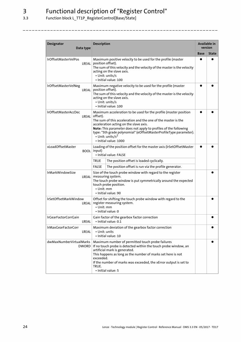
lrOffsetMasterVelPosLREAL
Maximum positive velocity to be used for the profile (master position offset).The sum of this velocity and the velocity of the master is the velocity acting on the slave axis.
• Unit: units/s• Initial value: 100
lrOffsetMasterVelNegLREAL
Maximum negative velocity to be used for the profile (master position offset).The sum of this velocity and the velocity of the master is the velocity acting on the slave axis.
• Unit: units/s• Initial value: 100
lrOffsetMasterAccDecLREAL
Maximum acceleration to be used for the profile (master position offset).The sum of this acceleration and the one of the master is the acceleration acting on the slave axis.Note: This parameter does not apply to profiles of the following type: "5th grade polynomial" (eOffsetMasterProfileType parameter).
• Unit: units/s2
• Initial value: 1000
xLoadOffsetMasterBOOL
Loading of the position offset for the master axis (lrSetOffsetMaster input)
• Initial value: FALSE
TRUE The position offset is loaded cyclically.
FALSE The position offset is run via the profile generator.
lrMarkWindowSizeLREAL
Size of the touch probe window with regard to the register measuring system.The touch probe window is put symmetrically around the expected touch probe position.
• Unit: mm• Initial value: 90
lrSetOffsetMarkWindowLREAL
Offset for shifting the touch probe window with regard to the register measuring system.
• Unit: mm• Initial value: 0
lrGearFactorCorrGainLREAL
Gain factor of the gearbox factor correction• Initial value: 0.1
lrMaxGearFactorCorrLREAL
Maximum deviation of the gearbox factor correction• Unit: units• Initial value: 10
dwMaxNumberVirtualMarksDWORD
Maximum number of permitted touch probe failuresIf no touch probe is detected within the touch probe window, an artificial mark is generated.This happens as long as the number of marks set here is not exceeded.If the number of marks was exceeded, the xError output is set to TRUE.
• Initial value: 5
DesignatorData type
Description Available in version
Base State
Lenze · Technology module | Register Control · Reference Manual · DMS 3.3 EN · 05/2017 · TD17 25
3 Functional description of "Register Control"3.4 State machine
_ _ _ _ _ _ _ _ _ _ _ _ _ _ _ _ _ _ _ _ _ _ _ _ _ _ _ _ _ _ _ _ _ _ _ _ _ _ _ _ _ _ _ _ _ _ _ _ _ _ _ _ _ _ _ _ _ _ _ _ _ _ _ _
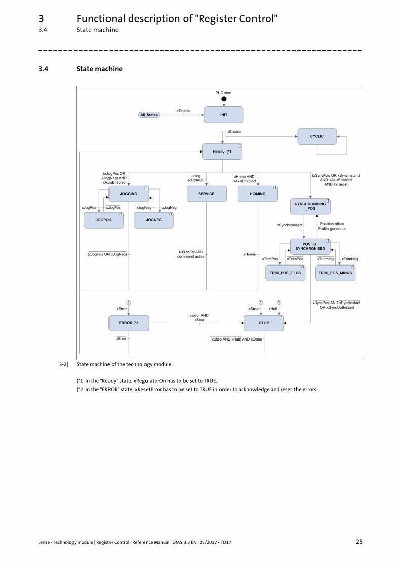
3.4 State machine
[3-2] State machine of the technology module
(*1 In the "Ready" state, xRegulatorOn has to be set to TRUE.
(*2 In the "ERROR" state, xResetError has to be set to TRUE in order to acknowledge and reset the errors.
3 Functional description of "Register Control"3.5 Signal flow diagrams
26 Lenze · Technology module | Register Control · Reference Manual · DMS 3.3 EN · 05/2017 · TD17
_ _ _ _ _ _ _ _ _ _ _ _ _ _ _ _ _ _ _ _ _ _ _ _ _ _ _ _ _ _ _ _ _ _ _ _ _ _ _ _ _ _ _ _ _ _ _ _ _ _ _ _ _ _ _ _ _ _ _ _ _ _ _ _
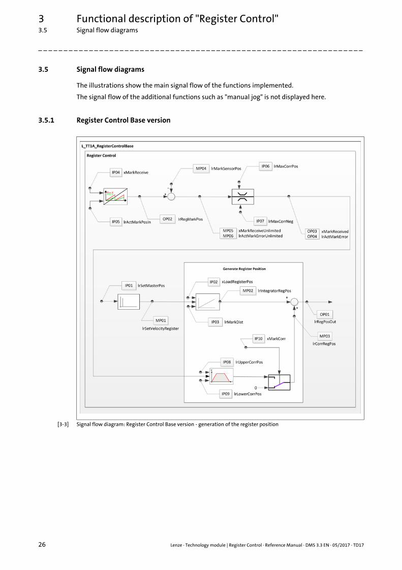
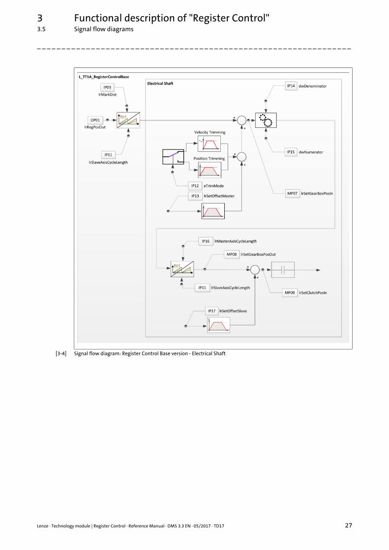
3.5 Signal flow diagrams
The illustrations show the main signal flow of the functions implemented.
The signal flow of the additional functions such as "manual jog" is not displayed here.
3.5.1 Register Control Base version
[3-3] Signal flow diagram: Register Control Base version - generation of the register position
Lenze · Technology module | Register Control · Reference Manual · DMS 3.3 EN · 05/2017 · TD17 27
3 Functional description of "Register Control"3.5 Signal flow diagrams
_ _ _ _ _ _ _ _ _ _ _ _ _ _ _ _ _ _ _ _ _ _ _ _ _ _ _ _ _ _ _ _ _ _ _ _ _ _ _ _ _ _ _ _ _ _ _ _ _ _ _ _ _ _ _ _ _ _ _ _ _ _ _ _
[3-4] Signal flow diagram: Register Control Base version - Electrical Shaft
3 Functional description of "Register Control"3.5 Signal flow diagrams
28 Lenze · Technology module | Register Control · Reference Manual · DMS 3.3 EN · 05/2017 · TD17
_ _ _ _ _ _ _ _ _ _ _ _ _ _ _ _ _ _ _ _ _ _ _ _ _ _ _ _ _ _ _ _ _ _ _ _ _ _ _ _ _ _ _ _ _ _ _ _ _ _ _ _ _ _ _ _ _ _ _ _ _ _ _ _
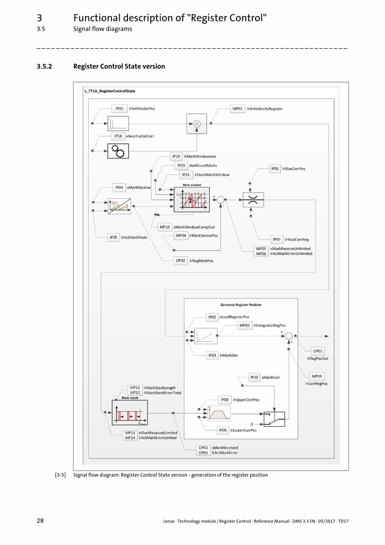
3.5.2 Register Control State version
[3-5] Signal flow diagram: Register Control State version - generation of the register position
Lenze · Technology module | Register Control · Reference Manual · DMS 3.3 EN · 05/2017 · TD17 29
3 Functional description of "Register Control"3.5 Signal flow diagrams
_ _ _ _ _ _ _ _ _ _ _ _ _ _ _ _ _ _ _ _ _ _ _ _ _ _ _ _ _ _ _ _ _ _ _ _ _ _ _ _ _ _ _ _ _ _ _ _ _ _ _ _ _ _ _ _ _ _ _ _ _ _ _ _
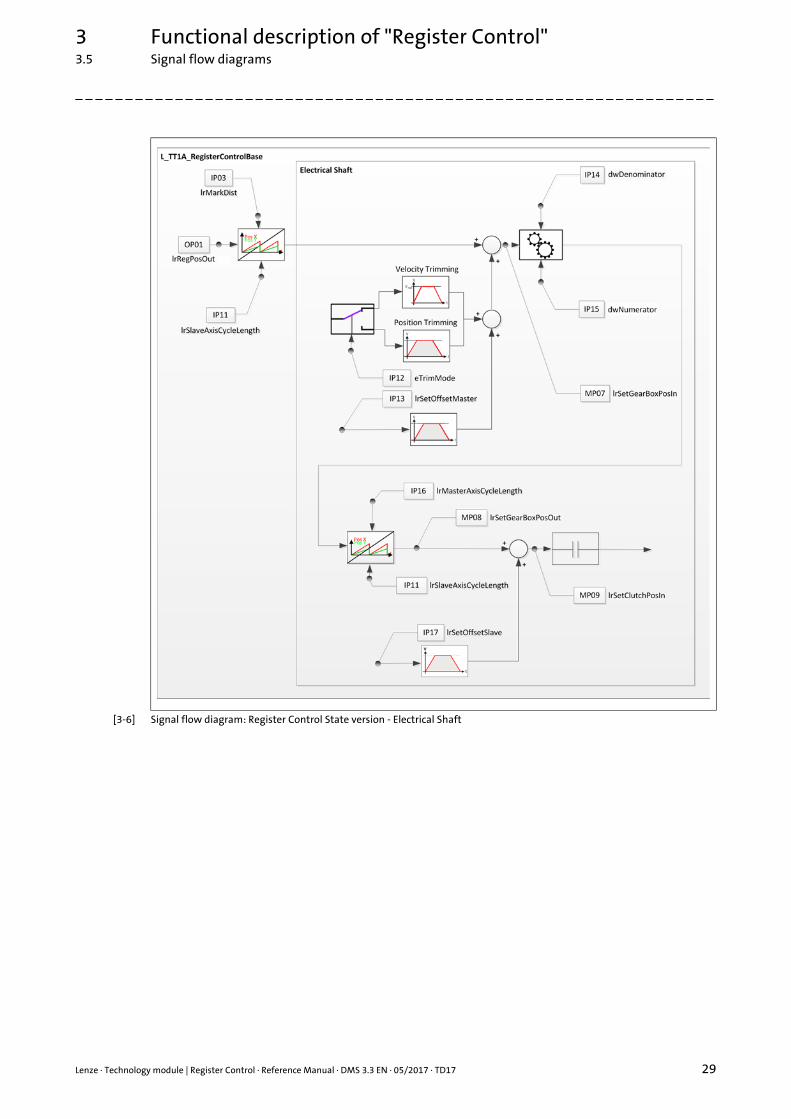
[3-6] Signal flow diagram: Register Control State version - Electrical Shaft
3 Functional description of "Register Control"3.5 Signal flow diagrams
30 Lenze · Technology module | Register Control · Reference Manual · DMS 3.3 EN · 05/2017 · TD17
_ _ _ _ _ _ _ _ _ _ _ _ _ _ _ _ _ _ _ _ _ _ _ _ _ _ _ _ _ _ _ _ _ _ _ _ _ _ _ _ _ _ _ _ _ _ _ _ _ _ _ _ _ _ _ _ _ _ _ _ _ _ _ _
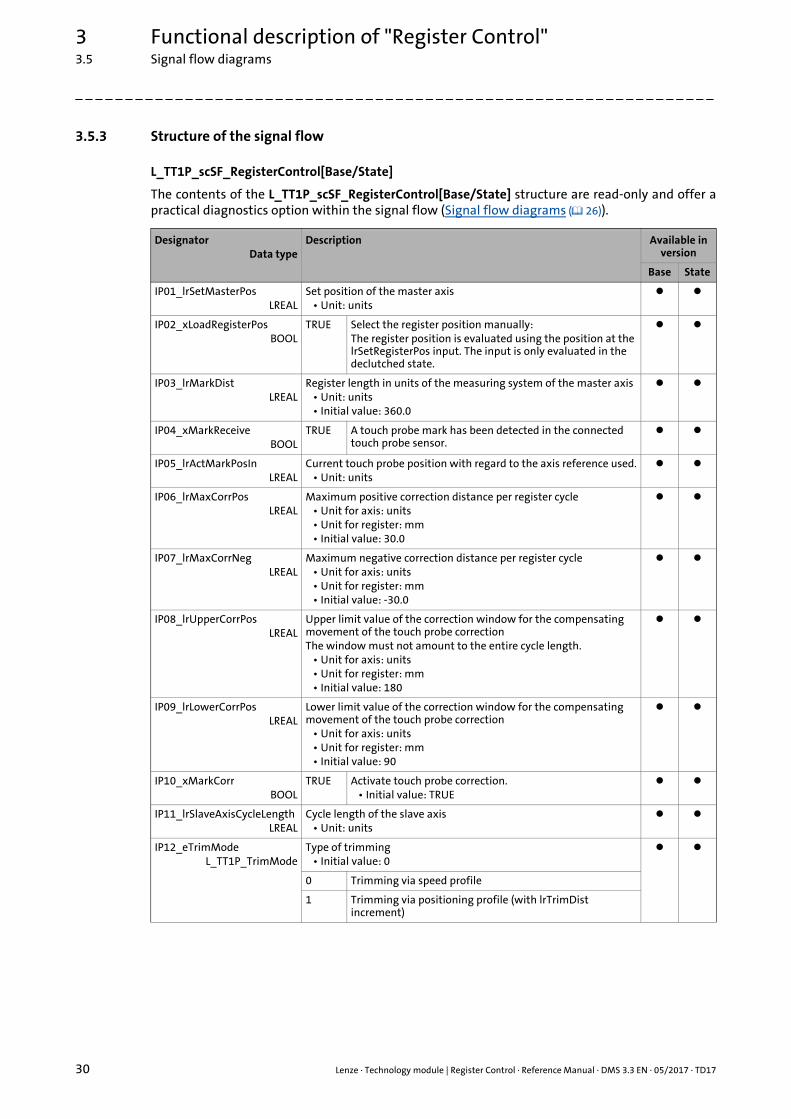
3.5.3 Structure of the signal flow
L_TT1P_scSF_RegisterControl[Base/State]
The contents of the L_TT1P_scSF_RegisterControl[Base/State] structure are read-only and offer apractical diagnostics option within the signal flow (Signal flow diagrams ( 26)).
DesignatorData type
Description Available in version
Base State
IP01_lrSetMasterPosLREAL
Set position of the master axis• Unit: units
IP02_xLoadRegisterPosBOOL
TRUE Select the register position manually:The register position is evaluated using the position at the lrSetRegisterPos input. The input is only evaluated in the declutched state.
IP03_lrMarkDistLREAL
Register length in units of the measuring system of the master axis• Unit: units• Initial value: 360.0
IP04_xMarkReceiveBOOL
TRUE A touch probe mark has been detected in the connected touch probe sensor.
IP05_lrActMarkPosInLREAL
Current touch probe position with regard to the axis reference used.• Unit: units
IP06_lrMaxCorrPosLREAL
Maximum positive correction distance per register cycle• Unit for axis: units• Unit for register: mm• Initial value: 30.0
IP07_lrMaxCorrNegLREAL
Maximum negative correction distance per register cycle• Unit for axis: units• Unit for register: mm• Initial value: -30.0
IP08_lrUpperCorrPosLREAL
Upper limit value of the correction window for the compensating movement of the touch probe correctionThe window must not amount to the entire cycle length.
• Unit for axis: units• Unit for register: mm• Initial value: 180
IP09_lrLowerCorrPosLREAL
Lower limit value of the correction window for the compensating movement of the touch probe correction
• Unit for axis: units• Unit for register: mm• Initial value: 90
IP10_xMarkCorrBOOL
TRUE Activate touch probe correction.• Initial value: TRUE
IP11_lrSlaveAxisCycleLengthLREAL
Cycle length of the slave axis• Unit: units
IP12_eTrimModeL_TT1P_TrimMode
Type of trimming• Initial value: 0
0 Trimming via speed profile
1 Trimming via positioning profile (with lrTrimDist increment)
Lenze · Technology module | Register Control · Reference Manual · DMS 3.3 EN · 05/2017 · TD17 31
3 Functional description of "Register Control"3.5 Signal flow diagrams
_ _ _ _ _ _ _ _ _ _ _ _ _ _ _ _ _ _ _ _ _ _ _ _ _ _ _ _ _ _ _ _ _ _ _ _ _ _ _ _ _ _ _ _ _ _ _ _ _ _ _ _ _ _ _ _ _ _ _ _ _ _ _ _
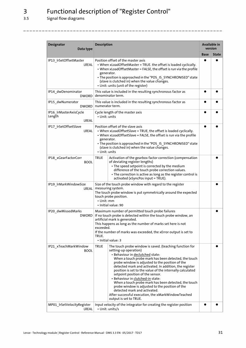
IP13_lrSetOffsetMasterLREAL
Position offset of the master axis• When xLoadOffsetMaster = TRUE. the offset is loaded cyclically.• When xLoadOffsetMaster = FALSE, the offset is run via the profile
generator.• The position is approached in the "POS_IS_SYNCHRONISED" state
(slave is clutched in) when the value changes.• Unit: units (unit of the register)
IP14_dwDenominatorDWORD
This value is included in the resulting synchronous factor as denominator term.
IP15_dwNumeratorDWORD
This value is included in the resulting synchronous factor as numerator term.
IP16_lrMasterAxisCycleLength
LREAL
Cycle length of the master axis• Unit: units
IP17_lrSetOffsetSlaveLREAL
Position offset of the slave axis• When xLoadOffsetSlave = TRUE, the offset is loaded cyclically.• When xLoadOffsetSlave = FALSE, the offset is run via the profile
generator.• The position is approached in the "POS_IS_SYNCHRONISED" state
(slave is clutched in) when the value changes.• Unit: units
IP18_xGearFactorCorrBOOL
TRUE Activation of the gearbox factor correction (compensation of deviating register lengths)
• The speed setpoint is corrected by the medium difference of the touch probe correction values.
• The correction is active as long as the register control is activated (xSyncPos input = TRUE).
IP19_lrMarkWindowSizeLREAL
Size of the touch probe window with regard to the register measuring system.The touch probe window is put symmetrically around the expected touch probe position.
• Unit: mm• Initial value: 90
IP20_dwMissedMarksDWORD
Maximum number of permitted touch probe failuresIf no touch probe is detected within the touch probe window, an artificial mark is generated.This happens as long as the number of marks set here is not exceeded.If the number of marks was exceeded, the xError output is set to TRUE.
• Initial value: 3
IP21_xTeachMarkWindowBOOL
TRUE The touch probe window is saved. (teaching function for setting-up operation)
• Behaviour in declutched state:When a touch probe mark has been detected, the touch probe window is adjusted to the position of the detected mark and activated. In addition, the register position is set to the value of the internally calculated setpoint position of the sensor.
• Behaviour in clutched-in state:When a touch probe mark has been detected, the touch probe window is adjusted to the position of the detected mark and activated.
After successful execution, the xMarkWindowTeached output is set to TRUE.
MP01_lrSetVelocityRegisterLREAL
Input velocity of the integrator for creating the register position• Unit: units/s
DesignatorData type
Description Available in version
Base State
3 Functional description of "Register Control"3.5 Signal flow diagrams
32 Lenze · Technology module | Register Control · Reference Manual · DMS 3.3 EN · 05/2017 · TD17
_ _ _ _ _ _ _ _ _ _ _ _ _ _ _ _ _ _ _ _ _ _ _ _ _ _ _ _ _ _ _ _ _ _ _ _ _ _ _ _ _ _ _ _ _ _ _ _ _ _ _ _ _ _ _ _ _ _ _ _ _ _ _ _
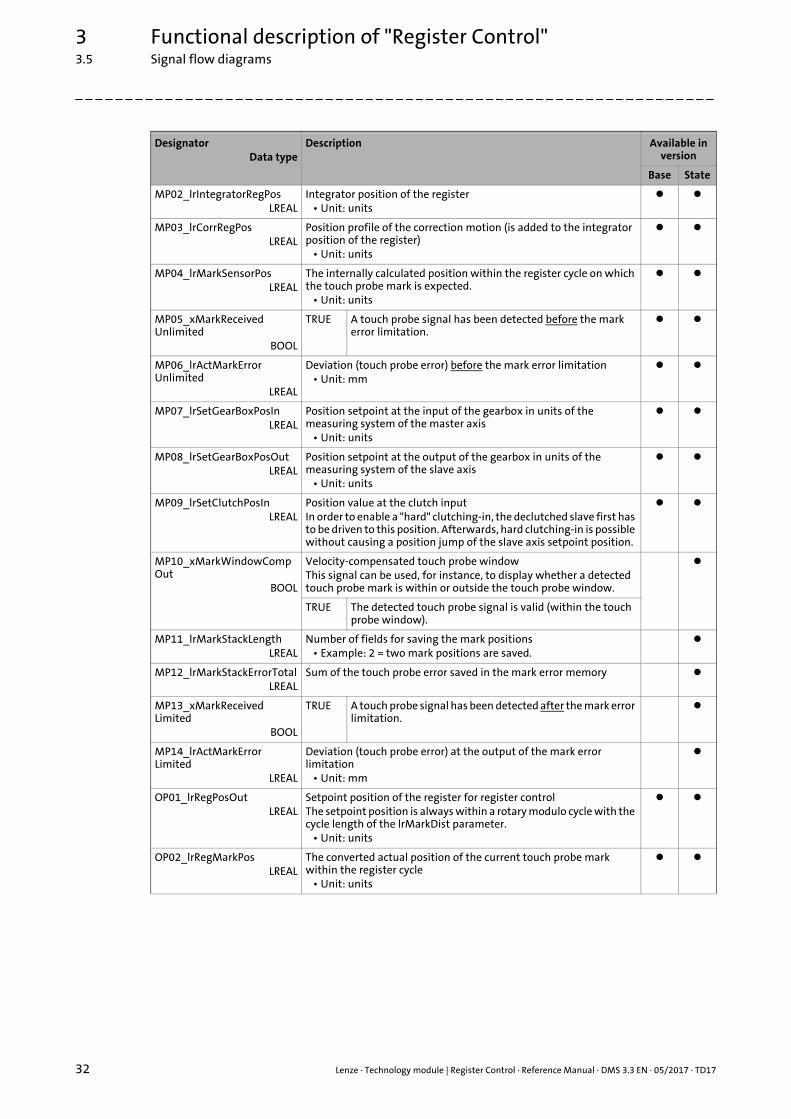
MP02_lrIntegratorRegPosLREAL
Integrator position of the register• Unit: units
MP03_lrCorrRegPosLREAL
Position profile of the correction motion (is added to the integrator position of the register)
• Unit: units
MP04_lrMarkSensorPosLREAL
The internally calculated position within the register cycle on which the touch probe mark is expected.
• Unit: units
MP05_xMarkReceivedUnlimited
BOOL
TRUE A touch probe signal has been detected before the mark error limitation.
MP06_lrActMarkErrorUnlimited
LREAL
Deviation (touch probe error) before the mark error limitation• Unit: mm
MP07_lrSetGearBoxPosInLREAL
Position setpoint at the input of the gearbox in units of the measuring system of the master axis
• Unit: units
MP08_lrSetGearBoxPosOutLREAL
Position setpoint at the output of the gearbox in units of the measuring system of the slave axis
• Unit: units
MP09_lrSetClutchPosInLREAL
Position value at the clutch inputIn order to enable a "hard" clutching-in, the declutched slave first has to be driven to this position. Afterwards, hard clutching-in is possible without causing a position jump of the slave axis setpoint position.
MP10_xMarkWindowCompOut
BOOL
Velocity-compensated touch probe windowThis signal can be used, for instance, to display whether a detected touch probe mark is within or outside the touch probe window.
TRUE The detected touch probe signal is valid (within the touch probe window).
MP11_lrMarkStackLengthLREAL
Number of fields for saving the mark positions• Example: 2 = two mark positions are saved.
MP12_lrMarkStackErrorTotalLREAL
Sum of the touch probe error saved in the mark error memory
MP13_xMarkReceivedLimited
BOOL
TRUE A touch probe signal has been detected after the mark error limitation.
MP14_lrActMarkErrorLimited
LREAL
Deviation (touch probe error) at the output of the mark error limitation
• Unit: mm
OP01_lrRegPosOutLREAL
Setpoint position of the register for register controlThe setpoint position is always within a rotary modulo cycle with the cycle length of the lrMarkDist parameter.
• Unit: units
OP02_lrRegMarkPosLREAL
The converted actual position of the current touch probe mark within the register cycle
• Unit: units
DesignatorData type
Description Available in version
Base State
Lenze · Technology module | Register Control · Reference Manual · DMS 3.3 EN · 05/2017 · TD17 33
3 Functional description of "Register Control"3.5 Signal flow diagrams
_ _ _ _ _ _ _ _ _ _ _ _ _ _ _ _ _ _ _ _ _ _ _ _ _ _ _ _ _ _ _ _ _ _ _ _ _ _ _ _ _ _ _ _ _ _ _ _ _ _ _ _ _ _ _ _ _ _ _ _ _ _ _ _
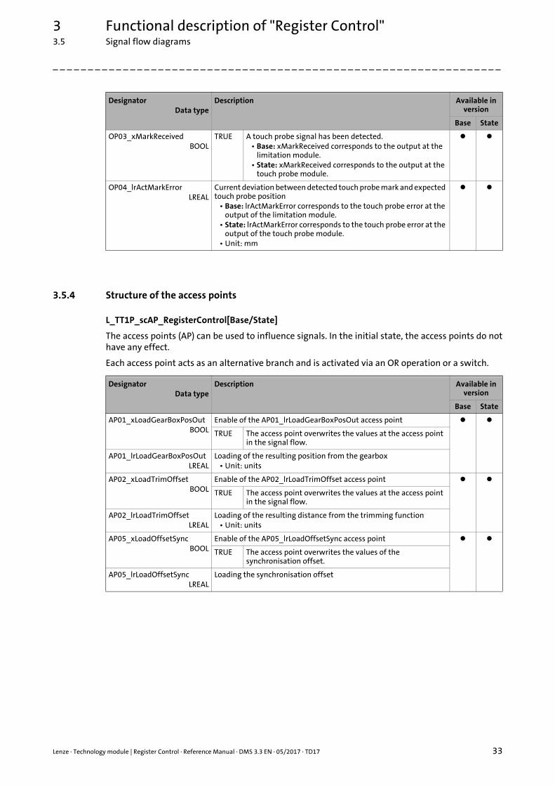
3.5.4 Structure of the access points
L_TT1P_scAP_RegisterControl[Base/State]
The access points (AP) can be used to influence signals. In the initial state, the access points do nothave any effect.
Each access point acts as an alternative branch and is activated via an OR operation or a switch.
OP03_xMarkReceivedBOOL
TRUE A touch probe signal has been detected.• Base: xMarkReceived corresponds to the output at the
limitation module.• State: xMarkReceived corresponds to the output at the
touch probe module.
OP04_lrActMarkErrorLREAL
Current deviation between detected touch probe mark and expected touch probe position
• Base: lrActMarkError corresponds to the touch probe error at the output of the limitation module.
• State: lrActMarkError corresponds to the touch probe error at the output of the touch probe module.
• Unit: mm
DesignatorData type
Description Available in version
Base State
DesignatorData type
Description Available in version
Base State
AP01_xLoadGearBoxPosOutBOOL
Enable of the AP01_lrLoadGearBoxPosOut access point
TRUE The access point overwrites the values at the access point in the signal flow.
AP01_lrLoadGearBoxPosOutLREAL
Loading of the resulting position from the gearbox• Unit: units
AP02_xLoadTrimOffsetBOOL
Enable of the AP02_lrLoadTrimOffset access point
TRUE The access point overwrites the values at the access point in the signal flow.
AP02_lrLoadTrimOffsetLREAL
Loading of the resulting distance from the trimming function• Unit: units
AP05_xLoadOffsetSyncBOOL
Enable of the AP05_lrLoadOffsetSync access point
TRUE The access point overwrites the values of the synchronisation offset.
AP05_lrLoadOffsetSyncLREAL
Loading the synchronisation offset
3 Functional description of "Register Control"3.6 Manual jog (jogging)
34 Lenze · Technology module | Register Control · Reference Manual · DMS 3.3 EN · 05/2017 · TD17
_ _ _ _ _ _ _ _ _ _ _ _ _ _ _ _ _ _ _ _ _ _ _ _ _ _ _ _ _ _ _ _ _ _ _ _ _ _ _ _ _ _ _ _ _ _ _ _ _ _ _ _ _ _ _ _ _ _ _ _ _ _ _ _
3.6 Manual jog (jogging)
Precondition
• The technology module is in the "Ready" state.
• The slave axis is enabled (xRegulatorOn = TRUE).
Execution
For manual jog of the axis, the manual jog speed lrJogVel is used.
If the xJogPos input is TRUE, the axis is traversed in positive direction and if the xJogNeg inputis TRUE, the axis is traversed in negative direction. The axis is executed for as long as the inputremains set to TRUE.
The current travel command cannot be replaced by another jog command. Only if both inputs havebeen reset, the State machine ( 25) changes to the "Ready" state again.
Parameters to be set
The parameters for the manual jog are located in the L_TT1P_scPar_RegisterControl[Base/State]( 20) parameter structure.
The parameter values can be changed during operation. They are accepted when the xJogPos orxJogNeg input is set to TRUE again.
lrJogVel : LREAL := 10; // Velocity [units/s]lrJogAcc : LREAL := 100; // Acceleration [units/s^2]lrJogDec : LREAL := 100; // Deceleration [units/s^2]lrJogJerk : LREAL := 10000; // Jerk [units/s^3]
Lenze · Technology module | Register Control · Reference Manual · DMS 3.3 EN · 05/2017 · TD17 35
3 Functional description of "Register Control"3.7 Homing
_ _ _ _ _ _ _ _ _ _ _ _ _ _ _ _ _ _ _ _ _ _ _ _ _ _ _ _ _ _ _ _ _ _ _ _ _ _ _ _ _ _ _ _ _ _ _ _ _ _ _ _ _ _ _ _ _ _ _ _ _ _ _ _
3.7 Homing
Precondition
• The technology module is in the "Ready" state.
• The slave axis is enabled (xRegulatorOn = TRUE).
Execution
Homing is started with a rising edge (FALSETRUE) at the xHomeExecute input. The axis will betravelling until the home position is reached. After successful homing, the State machine ( 25)changes back again to the "Ready" state.
The homing process is not interrupted if the xHomeExecute input is set to FALSE too early. Thefunction is aborted via the xStop input.
Parameters to be set
The parameters for homing are located in the L_TT1P_scPar_RegisterControl[Base/State] ( 20)parameter structure.
xUseHomeExtParameter : BOOL := FALSE;lrHomePosition : LREAL := 0.0;scHomeExtParameter : L_MC1P_HomeParameter;scHomeExtTP : MC_TRIGGER_REF;
3 Functional description of "Register Control"3.8 Synchronism (SyncPos) with clutch-in/declutch mechanism
36 Lenze · Technology module | Register Control · Reference Manual · DMS 3.3 EN · 05/2017 · TD17
_ _ _ _ _ _ _ _ _ _ _ _ _ _ _ _ _ _ _ _ _ _ _ _ _ _ _ _ _ _ _ _ _ _ _ _ _ _ _ _ _ _ _ _ _ _ _ _ _ _ _ _ _ _ _ _ _ _ _ _ _ _ _ _
3.8 Synchronism (SyncPos) with clutch-in/declutch mechanism
Execution
In order to obtain synchronism of the register and the slave axis, a register position is created withinthe technology module which serves as master position for the slave axis. The register position(lrSetRegPosOut output) is created by integrating the setpoint speed of the master axis within theregister cycle (lrMarkDist parameter).
The clutch function synchronises the register position (master position) to the slave axis. Here, thepositioning takes place without any position jump. Clutching-in starts at any position by setting thexSyncPos input = TRUE.
When declutching with xSyncPos = FALSE, the drive is braked to a standstill at the lrSlaveSyncOutPosposition and changed to the "Ready" state.
The lrSlaveSyncInDist parameters (for clutch-in) and lrSlaveSyncOutDist (for declutch) describe thepath of the slave axis via which the clutch process shall take place. For the initial values of theparameters, the clutch process has to be completed after 90 units.
Parameters to be set
The parameters for the clutch function are located in the L_TT1P_scPar_RegisterControl[Base/State] ( 20) parameter structure.
Example
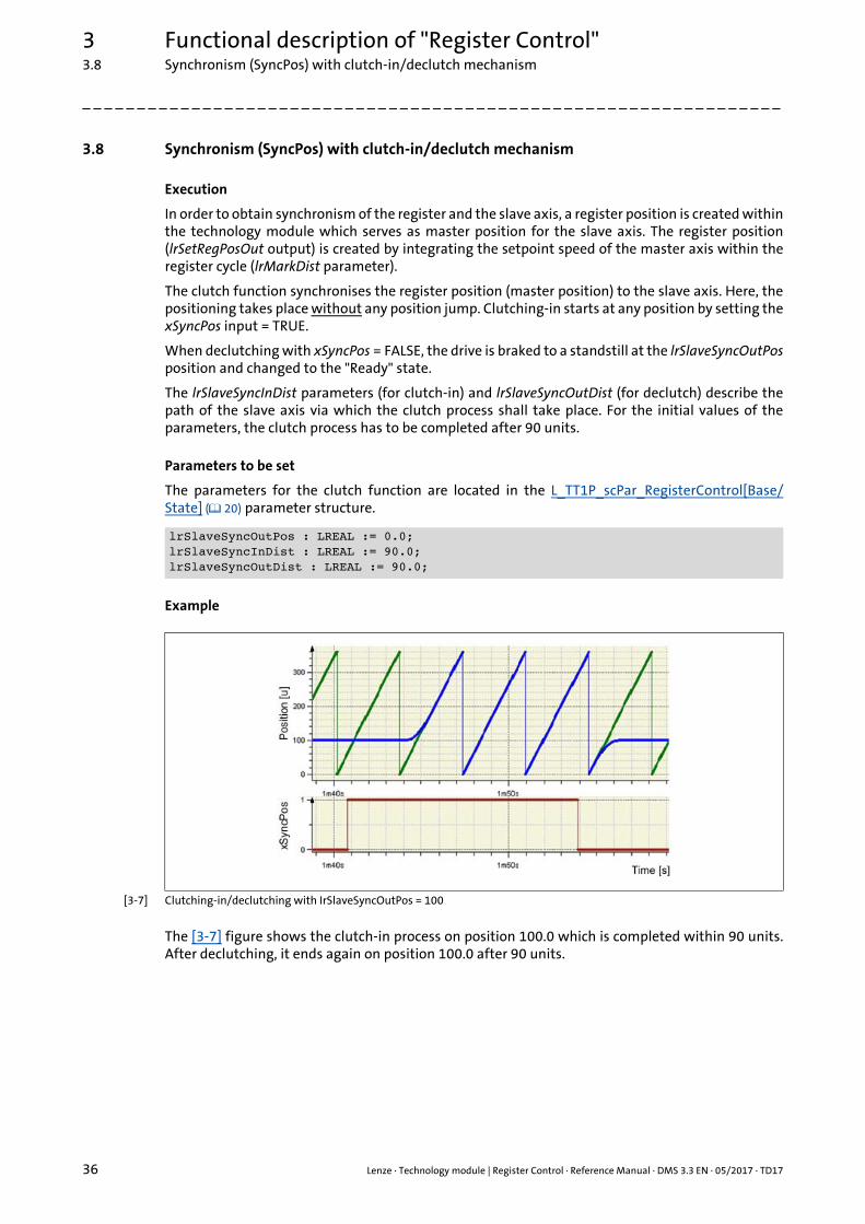
[3-7] Clutching-in/declutching with IrSlaveSyncOutPos = 100
The [3-7] figure shows the clutch-in process on position 100.0 which is completed within 90 units.After declutching, it ends again on position 100.0 after 90 units.
lrSlaveSyncOutPos : LREAL := 0.0;lrSlaveSyncInDist : LREAL := 90.0;lrSlaveSyncOutDist : LREAL := 90.0;
Lenze · Technology module | Register Control · Reference Manual · DMS 3.3 EN · 05/2017 · TD17 37
3 Functional description of "Register Control"3.8 Synchronism (SyncPos) with clutch-in/declutch mechanism
_ _ _ _ _ _ _ _ _ _ _ _ _ _ _ _ _ _ _ _ _ _ _ _ _ _ _ _ _ _ _ _ _ _ _ _ _ _ _ _ _ _ _ _ _ _ _ _ _ _ _ _ _ _ _ _ _ _ _ _ _ _ _ _
3.8.1 Direct clutching-in/declutching
The clutch function also provides for a direct clutching-in/declutching. For this purpose, set theparameters lrSlaveSyncInDist and lrSlaveSyncOutDist to the value 0.0. Clutching-in is then executeddirectly and abruptly.
In order to prevent a jump of the position at the clutch output and thus at the slave axis, thefollowing options are available:
• Positioning of the slave axis to the input position of the clutch (MP09:lrSetClutchPosIn) before clutching-in hard.This version offers a position synchronism without position offset between register and slave axis.More information on MP09:lrSetClutchPos can be found here: L_TT1P_scSF_RegisterControl[Base/State] ( 30).
• Automatic calculation and definition of the gearbox position for direct clutch-in with xLoadSyncPos parameter = TRUE.This version offers a position synchronism with position offset between the register and slave axis. The resulting position offset can be eliminated afterwards by applying an offset.
3 Functional description of "Register Control"3.8 Synchronism (SyncPos) with clutch-in/declutch mechanism
38 Lenze · Technology module | Register Control · Reference Manual · DMS 3.3 EN · 05/2017 · TD17
_ _ _ _ _ _ _ _ _ _ _ _ _ _ _ _ _ _ _ _ _ _ _ _ _ _ _ _ _ _ _ _ _ _ _ _ _ _ _ _ _ _ _ _ _ _ _ _ _ _ _ _ _ _ _ _ _ _ _ _ _ _ _ _
3.8.2 Relative clutching-in/declutching
These functions are selected via inputs and not via selecting a coupling mode. The selection of thegeneral coupling mode is not affected by this function.
When the xSyncInstant input = TRUE, the synchronisation is carried out with relative positioncoupling.
• If the master axis is at standstill, the slave axis directly (abruptly) clutches in to its current position.
• When the master axis is in motion, the slave axis immediately clutches in via the clutching distance in the lrSlaveSyncInDist parameter (by analogy with a velocity coupling).
• For declutching, the xSyncInstant input has no function.
When the xSyncOutInstant input = TRUE, it is declutched with relative position coupling.
• If the master axis is at standstill, the slave axis directly (abruptly) declutches from its current position.
• When the master axis is in motion, the slave axis immediately declutches via the clutching distance in the lrSlaveSyncOutDist parameter (by analogy with a velocity coupling or MC_Halt).
• For declutching, the xSyncOutInstant input has no function.
A position offset caused by relative clutching-in is displayed at the lrOffsetSyncPos output (in units).
Coupling behaviour if the inputs are stimulated at different times
Clutching-in via the xSyncInstant input:
Declutching via the xSyncOutInstant input:
Parameters to be set
The parameters for the clutch function are located in the L_TT1P_scPar_RegisterControl[Base/State] ( 20) parameter structure.
Combinations of the inputs Coupling behaviour
xSyncPos xSyncInstant
FALSETRUE FALSE Coupling behaviour as before
FALSE FALSETRUE No response
TRUE FALSETRUE No response
FALSETRUE FALSETRUE Relative clutching-in
FALSETRUE TRUE Relative clutching-in
Combinations of the inputs Coupling behaviour
xSyncPos xSyncOutInstant
TRUEFALSE FALSE Coupling behaviour as before
TRUEFALSE FALSETRUE Relative declutching
TRUE FALSETRUE Relative declutching
lrSlaveSyncInDist : LREAL := 90.0;lrSlaveSyncOutDist : LREAL := 90.0;eOffsetSlaveDirection : L_TT1P_Direction := 1;eOffsetSlaveProfileType : L_TT1P_ProfileType := 2;lrOffsetSlaveVelPos : LREAL := 100;lrOffsetSlaveVelNeg : LREAL := 100;lrOffsetSlaveAccDec : LREAL := 1000;
Lenze · Technology module | Register Control · Reference Manual · DMS 3.3 EN · 05/2017 · TD17 39
3 Functional description of "Register Control"3.9 Gearbox factor for different clock cycles
_ _ _ _ _ _ _ _ _ _ _ _ _ _ _ _ _ _ _ _ _ _ _ _ _ _ _ _ _ _ _ _ _ _ _ _ _ _ _ _ _ _ _ _ _ _ _ _ _ _ _ _ _ _ _ _ _ _ _ _ _ _ _ _
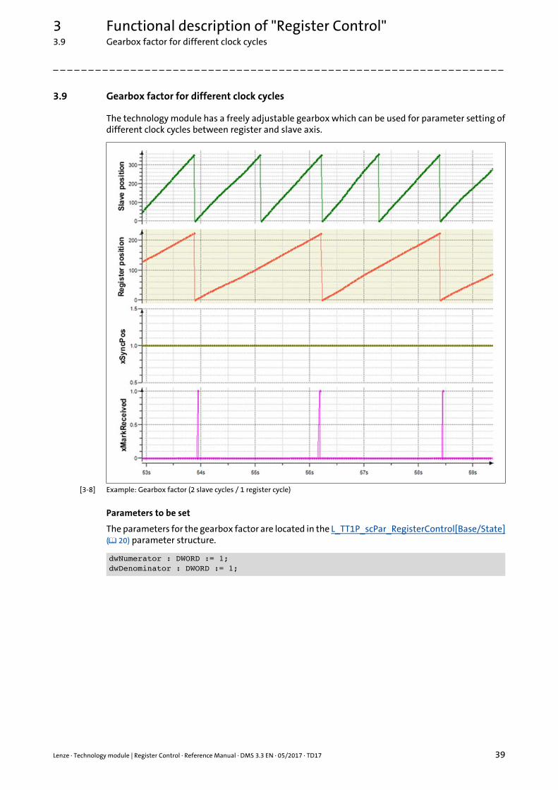
3.9 Gearbox factor for different clock cycles
The technology module has a freely adjustable gearbox which can be used for parameter setting ofdifferent clock cycles between register and slave axis.
[3-8] Example: Gearbox factor (2 slave cycles / 1 register cycle)
Parameters to be set
The parameters for the gearbox factor are located in the L_TT1P_scPar_RegisterControl[Base/State]( 20) parameter structure.
dwNumerator : DWORD := 1;dwDenominator : DWORD := 1;
3 Functional description of "Register Control"3.9 Gearbox factor for different clock cycles
40 Lenze · Technology module | Register Control · Reference Manual · DMS 3.3 EN · 05/2017 · TD17
_ _ _ _ _ _ _ _ _ _ _ _ _ _ _ _ _ _ _ _ _ _ _ _ _ _ _ _ _ _ _ _ _ _ _ _ _ _ _ _ _ _ _ _ _ _ _ _ _ _ _ _ _ _ _ _ _ _ _ _ _ _ _ _
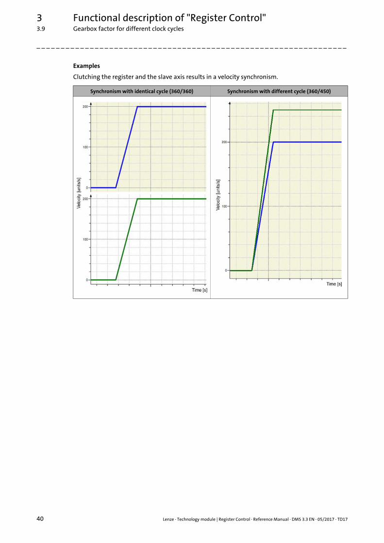
Examples
Clutching the register and the slave axis results in a velocity synchronism.
Synchronism with identical cycle (360/360) Synchronism with different cycle (360/450)
Lenze · Technology module | Register Control · Reference Manual · DMS 3.3 EN · 05/2017 · TD17 41
3 Functional description of "Register Control"3.10 Position offset during synchronism
_ _ _ _ _ _ _ _ _ _ _ _ _ _ _ _ _ _ _ _ _ _ _ _ _ _ _ _ _ _ _ _ _ _ _ _ _ _ _ _ _ _ _ _ _ _ _ _ _ _ _ _ _ _ _ _ _ _ _ _ _ _ _ _
3.10 Position offset during synchronism
Precondition
Setting a position offset is only possible in the "POS_IS_SYCHRONISED" state.
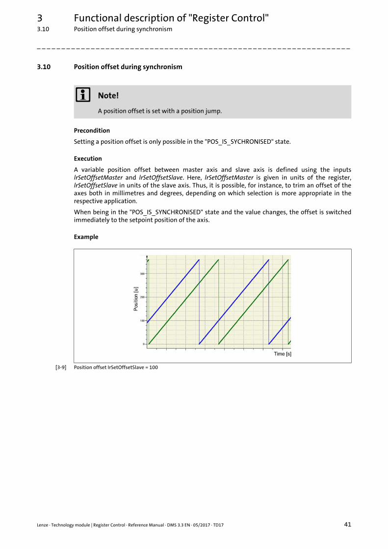
Execution
A variable position offset between master axis and slave axis is defined using the inputslrSetOffsetMaster and lrSetOffsetSlave. Here, lrSetOffsetMaster is given in units of the register,lrSetOffsetSlave in units of the slave axis. Thus, it is possible, for instance, to trim an offset of theaxes both in millimetres and degrees, depending on which selection is more appropriate in therespective application.
When being in the "POS_IS_SYNCHRONISED" state and the value changes, the offset is switchedimmediately to the setpoint position of the axis.
Example
[3-9] Position offset IrSetOffsetSlave = 100
Note!
A position offset is set with a position jump.
3 Functional description of "Register Control"3.11 Trimming
42 Lenze · Technology module | Register Control · Reference Manual · DMS 3.3 EN · 05/2017 · TD17
_ _ _ _ _ _ _ _ _ _ _ _ _ _ _ _ _ _ _ _ _ _ _ _ _ _ _ _ _ _ _ _ _ _ _ _ _ _ _ _ _ _ _ _ _ _ _ _ _ _ _ _ _ _ _ _ _ _ _ _ _ _ _ _
3.11 Trimming
Precondition
Trimming is only possible in the "POS_IS_SYCHRONISED" state.
Execution
Trimming enables the position of the slave axis to be adjusted towards the master axis by"tipping" – as in case of Manual jog (jogging) ( 34).
The eTrimMode parameter serves to change over between an "increment trimming" and a "speedtrimming":
• For "increment trimming", the lrTrimDist parameter is used to define the increment to be trimmed.
• Velocity trimming is started by setting the input xTrimPos or xTrimNeg to TRUE. The "POS_IS_SYCHRONISED" state then changes to "TRIM_POS_PLUS" or "TRIM_POS_MINUS", depending on the direction, and only leaves it when the respective input xTrimPos or xTrimNeg is reset to FALSE.
Offsets adjusted by trimming can be detected via the lrOffsetTrim output. The value of lrOffsetTrimcan be reset to zero by switching of the technology module.
Parameters to be set
The parameters for position trimming are located in the L_TT1P_scPar_RegisterControl[Base/State]( 20) parameter structure.
The acceleration and velocity of the trimming superimpose the ones of the master axis. Hence, theresults for the axis to be trimmed are as follows:
• Resulting velocity of: vAxisRes = vMasterAxis + lrTrimVel
• Resulting acceleration of: aAxisRes = aMasterAxis + lrTrimAcc
eTrimMode : L_TT1P_TrimMode := 0;lrTrimDist : LREAL := 1.0;lrJerk : LREAL := 10000;lrTrimAcc : LREAL := 100;lrTrimDec : LREAL := 100;lrTrimVel : LREAL := 50;
Lenze · Technology module | Register Control · Reference Manual · DMS 3.3 EN · 05/2017 · TD17 43
3 Functional description of "Register Control"3.12 Register control
_ _ _ _ _ _ _ _ _ _ _ _ _ _ _ _ _ _ _ _ _ _ _ _ _ _ _ _ _ _ _ _ _ _ _ _ _ _ _ _ _ _ _ _ _ _ _ _ _ _ _ _ _ _ _ _ _ _ _ _ _ _ _ _
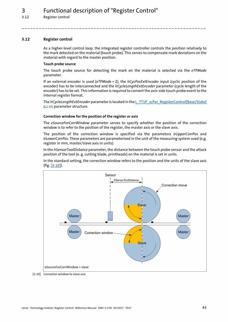
3.12 Register control
As a higher-level control loop, the integrated register controller controls the position relatively tothe mark detected on the material (touch probe). This serves to compensate mark deviations on thematerial with regard to the master position.
Touch probe source
The touch probe source for detecting the mark on the material is selected via the eTPModeparameter.
If an external encoder is used (eTPMode = 2), the lrCycPosExtEncoder input (cyclic position of theencoder) has to be interconnected and the lrCycleLengthExtEncoder parameter (cycle length of theencoder) has to be set. This information is required to convert the axis-side touch probe event to theinternal register format.
The lrCycleLengthExtEncoder parameter is located in the L_TT1P_scPar_RegisterControl[Base/State]( 20) parameter structure.
Correction window for the position of the register or axis
The eSourceForCorrWindow parameter serves to specify whether the position of the correctionwindow is to refer to the position of the register, the master axis or the slave axis.
The position of the correction window is specified via the parameters lrUpperCorrPos andlrLowerCorrPos. These parameters are parameterised in the unit of the measuring system used (e.g.register in mm, master/slave axis in units).
In the lrSensorToolDistance parameter, the distance between the touch probe sensor and the attackposition of the tool (e. g. cutting blade, printheads) on the material is set in units.
In the standard setting, the correction window refers to the position and the units of the slave axis(fig. [3-10]).
[3-10] Correction window to slave axis
eSourceForCorrWindow = slave
3 Functional description of "Register Control"3.12 Register control
44 Lenze · Technology module | Register Control · Reference Manual · DMS 3.3 EN · 05/2017 · TD17
_ _ _ _ _ _ _ _ _ _ _ _ _ _ _ _ _ _ _ _ _ _ _ _ _ _ _ _ _ _ _ _ _ _ _ _ _ _ _ _ _ _ _ _ _ _ _ _ _ _ _ _ _ _ _ _ _ _ _ _ _ _ _ _
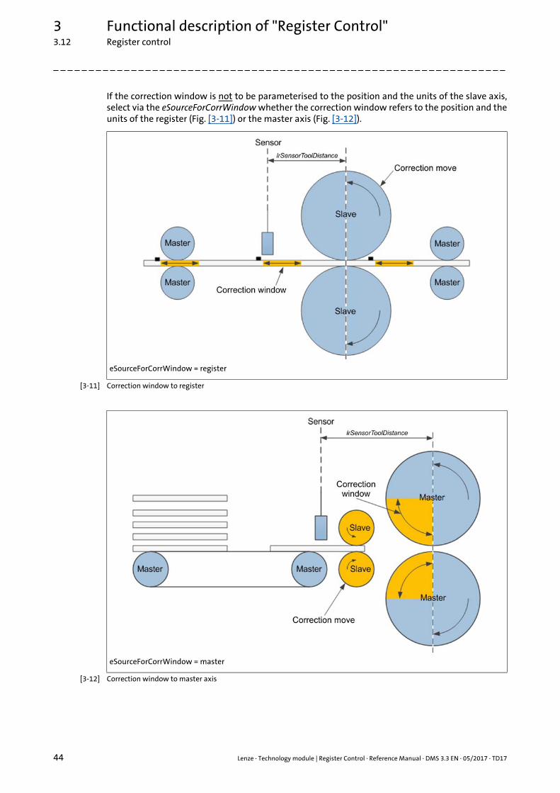
If the correction window is not to be parameterised to the position and the units of the slave axis,select via the eSourceForCorrWindow whether the correction window refers to the position and theunits of the register (Fig. [3-11]) or the master axis (Fig. [3-12]).
[3-11] Correction window to register
[3-12] Correction window to master axis
eSourceForCorrWindow = register
eSourceForCorrWindow = master
Lenze · Technology module | Register Control · Reference Manual · DMS 3.3 EN · 05/2017 · TD17 45
3 Functional description of "Register Control"3.12 Register control
_ _ _ _ _ _ _ _ _ _ _ _ _ _ _ _ _ _ _ _ _ _ _ _ _ _ _ _ _ _ _ _ _ _ _ _ _ _ _ _ _ _ _ _ _ _ _ _ _ _ _ _ _ _ _ _ _ _ _ _ _ _ _ _
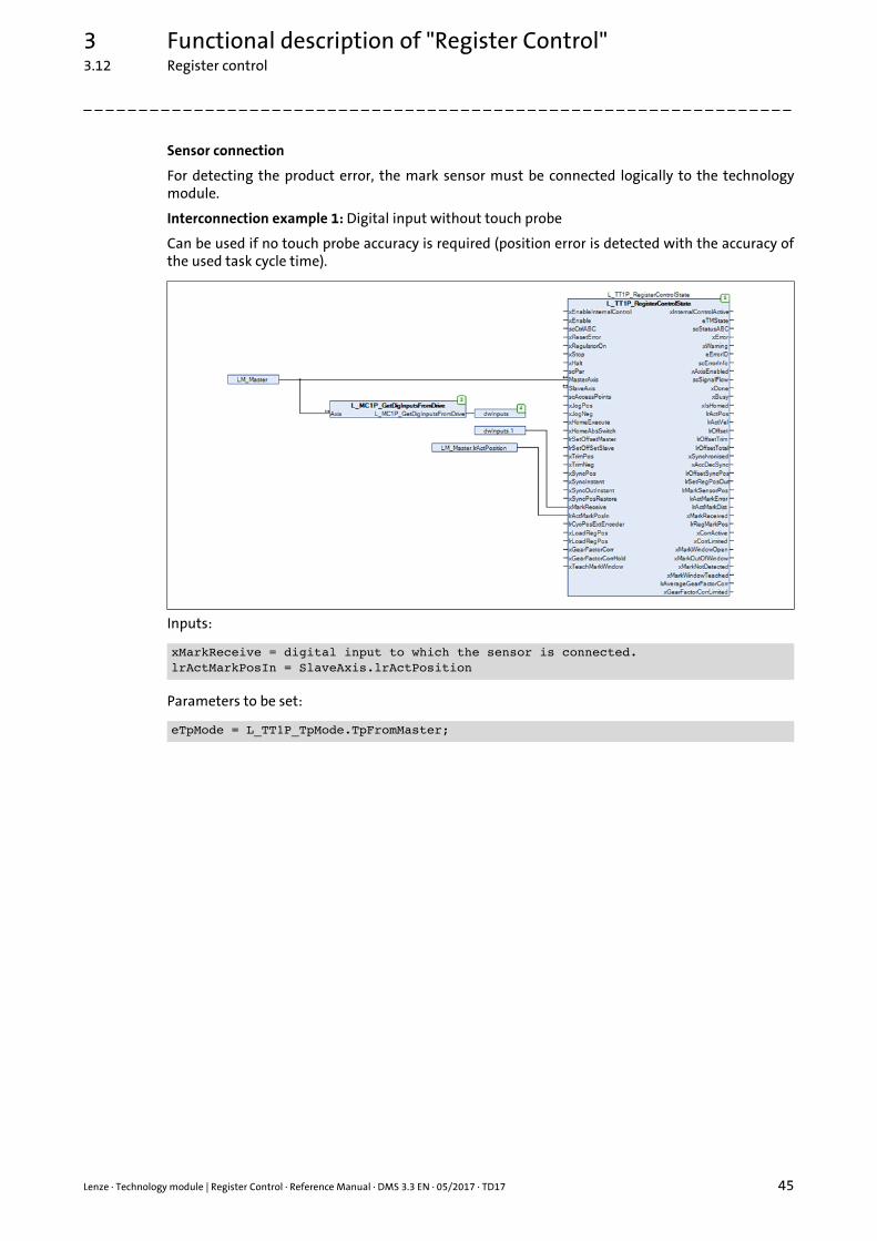
Sensor connection
For detecting the product error, the mark sensor must be connected logically to the technologymodule.
Interconnection example 1: Digital input without touch probe
Can be used if no touch probe accuracy is required (position error is detected with the accuracy ofthe used task cycle time).
Inputs:
Parameters to be set:
xMarkReceive = digital input to which the sensor is connected.lrActMarkPosIn = SlaveAxis.lrActPosition
eTpMode = L_TT1P_TpMode.TpFromMaster;
3 Functional description of "Register Control"3.12 Register control
46 Lenze · Technology module | Register Control · Reference Manual · DMS 3.3 EN · 05/2017 · TD17
_ _ _ _ _ _ _ _ _ _ _ _ _ _ _ _ _ _ _ _ _ _ _ _ _ _ _ _ _ _ _ _ _ _ _ _ _ _ _ _ _ _ _ _ _ _ _ _ _ _ _ _ _ _ _ _ _ _ _ _ _ _ _ _
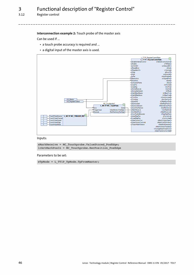
Interconnection example 2: Touch probe of the master axis
Can be used if ...
• a touch probe accuracy is required and ...
• a digital input of the master axis is used.
Inputs:
Parameters to be set:
xMarkReceive = MC_Touchprobe.ValueStored_PosEdge;lrActMarkPosIn = MC_Touchprobe.RecPosition_PosEdge
eTpMode = L_TT1P_TpMode.TpFromMaster;
Lenze · Technology module | Register Control · Reference Manual · DMS 3.3 EN · 05/2017 · TD17 47
3 Functional description of "Register Control"3.12 Register control
_ _ _ _ _ _ _ _ _ _ _ _ _ _ _ _ _ _ _ _ _ _ _ _ _ _ _ _ _ _ _ _ _ _ _ _ _ _ _ _ _ _ _ _ _ _ _ _ _ _ _ _ _ _ _ _ _ _ _ _ _ _ _ _
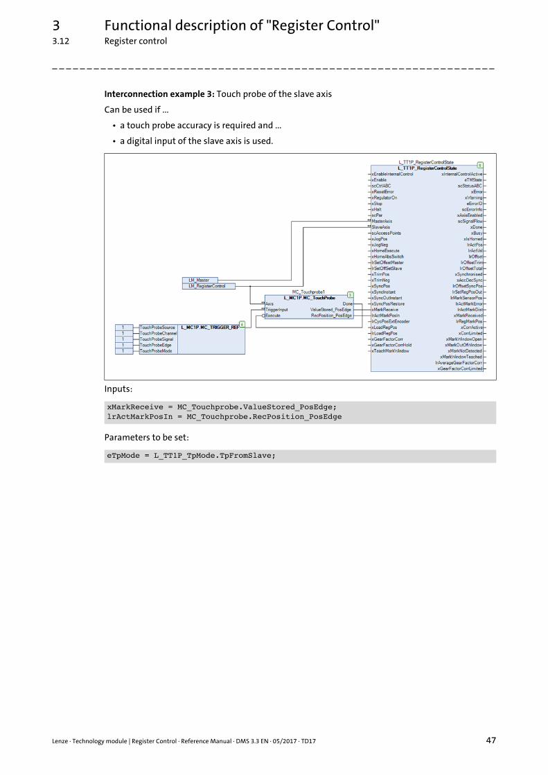
Interconnection example 3: Touch probe of the slave axis
Can be used if ...
• a touch probe accuracy is required and ...
• a digital input of the slave axis is used.
Inputs:
Parameters to be set:
xMarkReceive = MC_Touchprobe.ValueStored_PosEdge;lrActMarkPosIn = MC_Touchprobe.RecPosition_PosEdge
eTpMode = L_TT1P_TpMode.TpFromSlave;
3 Functional description of "Register Control"3.13 Teaching function
48 Lenze · Technology module | Register Control · Reference Manual · DMS 3.3 EN · 05/2017 · TD17
_ _ _ _ _ _ _ _ _ _ _ _ _ _ _ _ _ _ _ _ _ _ _ _ _ _ _ _ _ _ _ _ _ _ _ _ _ _ _ _ _ _ _ _ _ _ _ _ _ _ _ _ _ _ _ _ _ _ _ _ _ _ _ _
3.13 Teaching function
The teaching function is executed by setting the xTeachMarkWindow input = TRUE.
Here, the touch probe window is put with the width in lrMarkWindowSize parameter symmetrically(+/- lrMarkWindowSize / 2) around the current touch probe mark.
The current register position is set to the internally calculated value of the sensor position.
The lrActMarkDist output contains the register length between the last two touch probe marks inunits (units of the master axis).
The lrMarkDist parameter corresponds to the register length in units.
Alternatively to teaching, you can also enter the width of the touch probe window manually into thelrMarkWindowSize parameter.
Parameters to be set
The parameters for the teaching function are located in the L_TT1P_scPar_RegisterControl[Base/State] ( 20) parameter structure.
lrMarkWindowSize : LREAL := 90; // [mm]lrMarkDist : LREAL := 360.0; // [units]
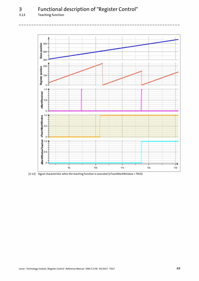
Lenze · Technology module | Register Control · Reference Manual · DMS 3.3 EN · 05/2017 · TD17 49
3 Functional description of "Register Control"3.13 Teaching function
_ _ _ _ _ _ _ _ _ _ _ _ _ _ _ _ _ _ _ _ _ _ _ _ _ _ _ _ _ _ _ _ _ _ _ _ _ _ _ _ _ _ _ _ _ _ _ _ _ _ _ _ _ _ _ _ _ _ _ _ _ _ _ _
[3-13] Signal characteristic when the teaching function is executed (xTeachMarkWindow = TRUE)
3 Functional description of "Register Control"3.14 Touch probe failure detection
50 Lenze · Technology module | Register Control · Reference Manual · DMS 3.3 EN · 05/2017 · TD17
_ _ _ _ _ _ _ _ _ _ _ _ _ _ _ _ _ _ _ _ _ _ _ _ _ _ _ _ _ _ _ _ _ _ _ _ _ _ _ _ _ _ _ _ _ _ _ _ _ _ _ _ _ _ _ _ _ _ _ _ _ _ _ _
3.14 Touch probe failure detection
When the xMarkNotDetected output is set to TRUE, no touch probe is detected within theparameterised touch probe window. In this case, an ideal virtual mark is created for the system inorder that downstream functions can continued to be executed.
The dwMaxMissedMarks parameter serves to define the maximum number of virtual marks thatmay occur successively. The current actual position of the touch probe is assumed on the exactposition of the touch probe sensor. Thus, there is no compensating movement for the register cyclesin which virtual marks occur.
If the number of successively occurring virtual marks is exceeded, the technology module is set tothe "ERROR" state and an error message is output.
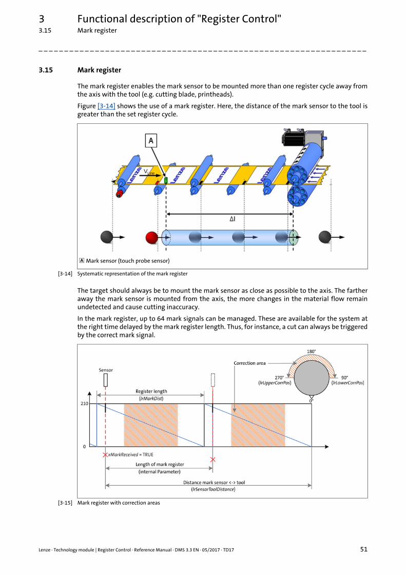
Lenze · Technology module | Register Control · Reference Manual · DMS 3.3 EN · 05/2017 · TD17 51
3 Functional description of "Register Control"3.15 Mark register
_ _ _ _ _ _ _ _ _ _ _ _ _ _ _ _ _ _ _ _ _ _ _ _ _ _ _ _ _ _ _ _ _ _ _ _ _ _ _ _ _ _ _ _ _ _ _ _ _ _ _ _ _ _ _ _ _ _ _ _ _ _ _ _
3.15 Mark register
The mark register enables the mark sensor to be mounted more than one register cycle away fromthe axis with the tool (e.g. cutting blade, printheads).
Figure [3-14] shows the use of a mark register. Here, the distance of the mark sensor to the tool isgreater than the set register cycle.
[3-14] Systematic representation of the mark register
The target should always be to mount the mark sensor as close as possible to the axis. The fartheraway the mark sensor is mounted from the axis, the more changes in the material flow remainundetected and cause cutting inaccuracy.
In the mark register, up to 64 mark signals can be managed. These are available for the system atthe right time delayed by the mark register length. Thus, for instance, a cut can always be triggeredby the correct mark signal.
[3-15] Mark register with correction areas
Mark sensor (touch probe sensor)
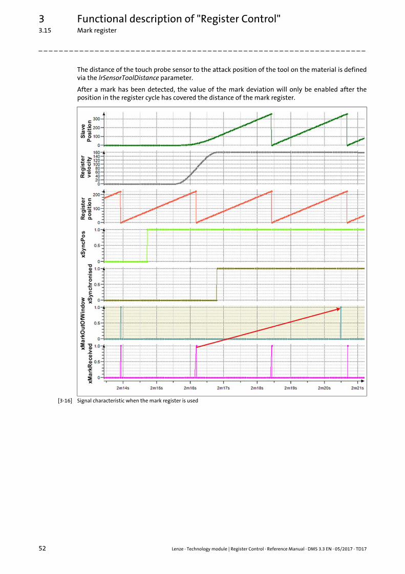
3 Functional description of "Register Control"3.15 Mark register
52 Lenze · Technology module | Register Control · Reference Manual · DMS 3.3 EN · 05/2017 · TD17
_ _ _ _ _ _ _ _ _ _ _ _ _ _ _ _ _ _ _ _ _ _ _ _ _ _ _ _ _ _ _ _ _ _ _ _ _ _ _ _ _ _ _ _ _ _ _ _ _ _ _ _ _ _ _ _ _ _ _ _ _ _ _ _
The distance of the touch probe sensor to the attack position of the tool on the material is definedvia the lrSensorToolDistance parameter.
After a mark has been detected, the value of the mark deviation will only be enabled after theposition in the register cycle has covered the distance of the mark register.
[3-16] Signal characteristic when the mark register is used
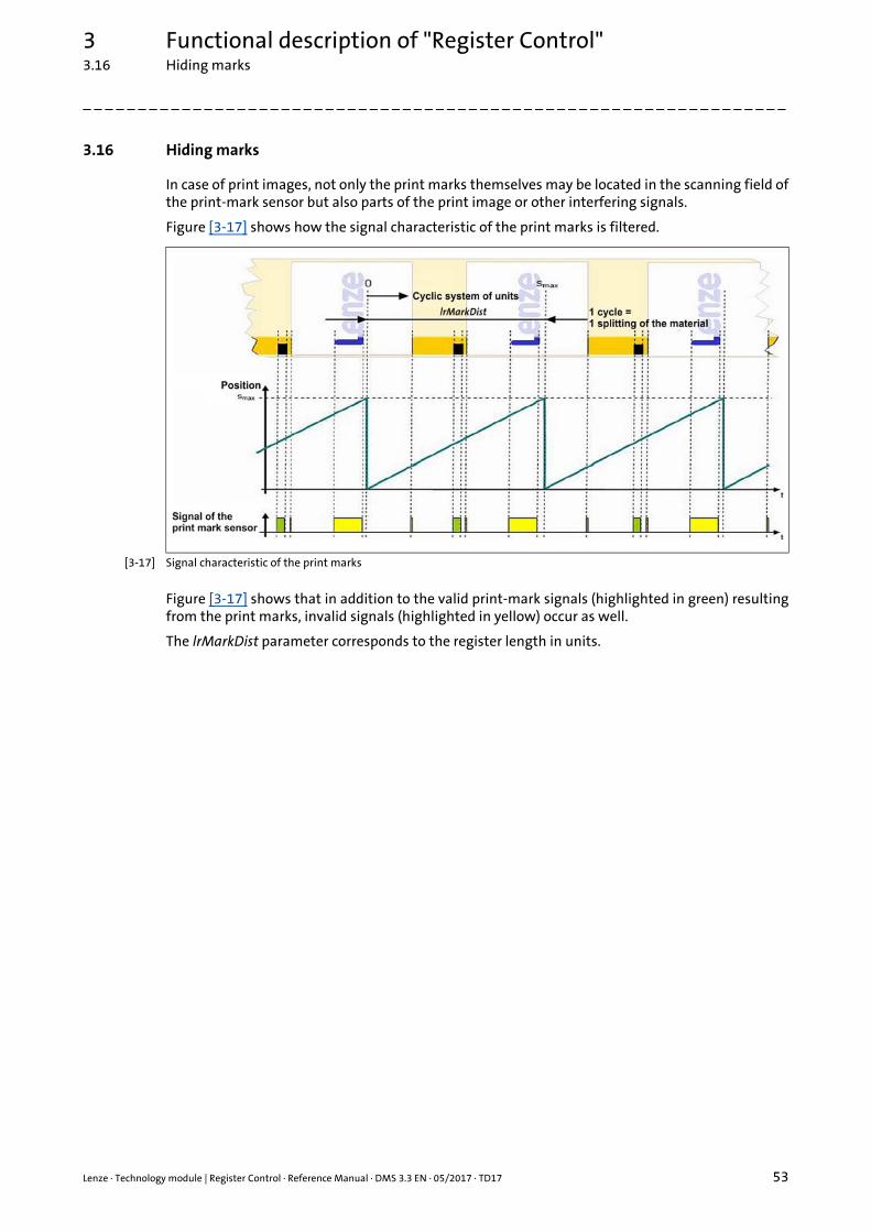
Lenze · Technology module | Register Control · Reference Manual · DMS 3.3 EN · 05/2017 · TD17 53
3 Functional description of "Register Control"3.16 Hiding marks
_ _ _ _ _ _ _ _ _ _ _ _ _ _ _ _ _ _ _ _ _ _ _ _ _ _ _ _ _ _ _ _ _ _ _ _ _ _ _ _ _ _ _ _ _ _ _ _ _ _ _ _ _ _ _ _ _ _ _ _ _ _ _ _
3.16 Hiding marks
In case of print images, not only the print marks themselves may be located in the scanning field ofthe print-mark sensor but also parts of the print image or other interfering signals.
Figure [3-17] shows how the signal characteristic of the print marks is filtered.
[3-17] Signal characteristic of the print marks
Figure [3-17] shows that in addition to the valid print-mark signals (highlighted in green) resultingfrom the print marks, invalid signals (highlighted in yellow) occur as well.
The lrMarkDist parameter corresponds to the register length in units.
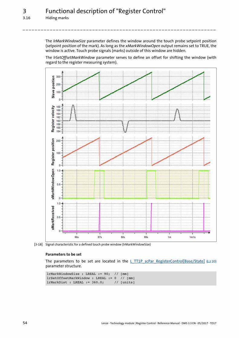
3 Functional description of "Register Control"3.16 Hiding marks
54 Lenze · Technology module | Register Control · Reference Manual · DMS 3.3 EN · 05/2017 · TD17
_ _ _ _ _ _ _ _ _ _ _ _ _ _ _ _ _ _ _ _ _ _ _ _ _ _ _ _ _ _ _ _ _ _ _ _ _ _ _ _ _ _ _ _ _ _ _ _ _ _ _ _ _ _ _ _ _ _ _ _ _ _ _ _
The lrMarkWindowSize parameter defines the window around the touch probe setpoint position(setpoint position of the mark). As long as the xMarkWindowOpen output remains set to TRUE, thewindow is active. Touch probe signals (marks) outside of this window are hidden.
The lrSetOffsetMarkWindow parameter serves to define an offset for shifting the window (withregard to the register measuring system).
[3-18] Signal characteristic for a defined touch probe window (lrMarkWindowSize)
Parameters to be set
The parameters to be set are located in the L_TT1P_scPar_RegisterControl[Base/State] ( 20)parameter structure.
lrMarkWindowSize : LREAL := 90; // [mm]lrSetOffsetMarkWindow : LREAL := 0 // [mm]lrMarkDist : LREAL := 360.0; // [units]
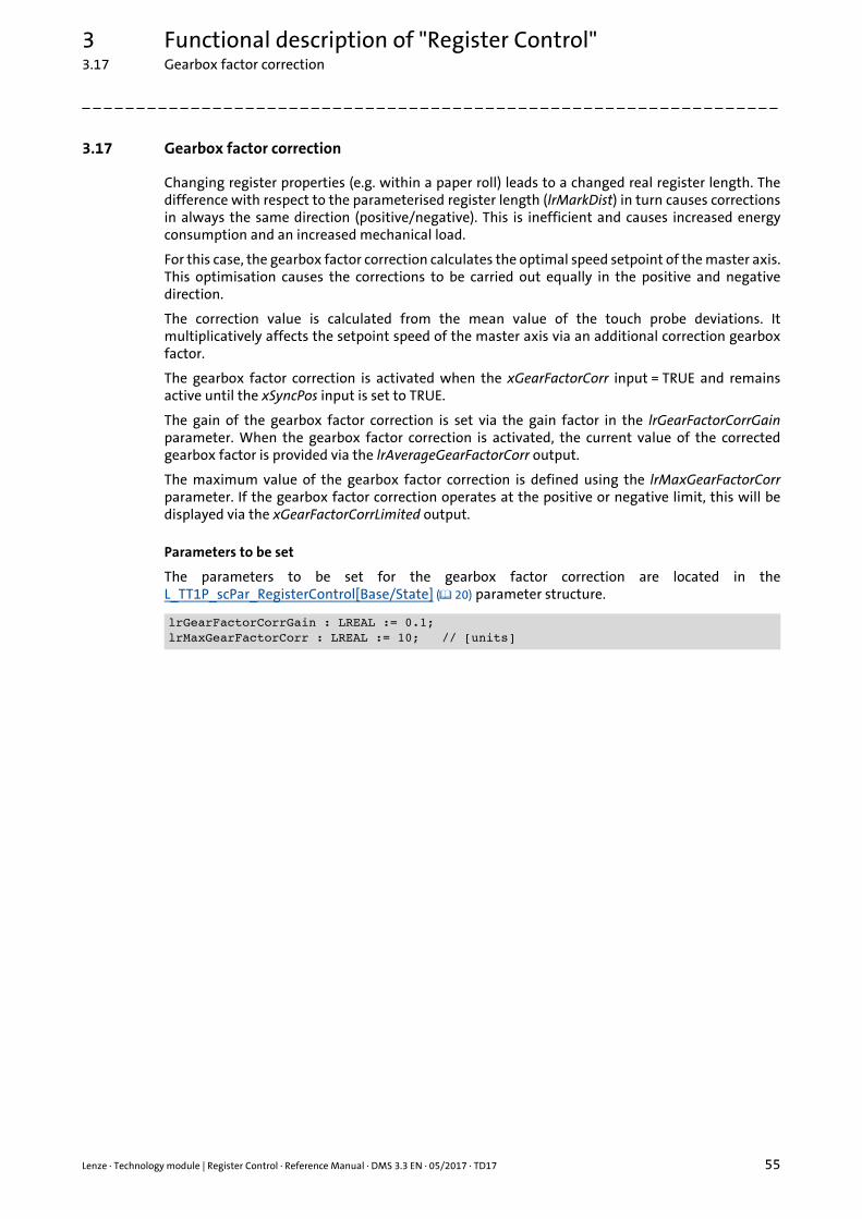
Lenze · Technology module | Register Control · Reference Manual · DMS 3.3 EN · 05/2017 · TD17 55
3 Functional description of "Register Control"3.17 Gearbox factor correction
_ _ _ _ _ _ _ _ _ _ _ _ _ _ _ _ _ _ _ _ _ _ _ _ _ _ _ _ _ _ _ _ _ _ _ _ _ _ _ _ _ _ _ _ _ _ _ _ _ _ _ _ _ _ _ _ _ _ _ _ _ _ _ _
3.17 Gearbox factor correction
Changing register properties (e.g. within a paper roll) leads to a changed real register length. Thedifference with respect to the parameterised register length (lrMarkDist) in turn causes correctionsin always the same direction (positive/negative). This is inefficient and causes increased energyconsumption and an increased mechanical load.
For this case, the gearbox factor correction calculates the optimal speed setpoint of the master axis.This optimisation causes the corrections to be carried out equally in the positive and negativedirection.
The correction value is calculated from the mean value of the touch probe deviations. Itmultiplicatively affects the setpoint speed of the master axis via an additional correction gearboxfactor.
The gearbox factor correction is activated when the xGearFactorCorr input = TRUE and remainsactive until the xSyncPos input is set to TRUE.
The gain of the gearbox factor correction is set via the gain factor in the lrGearFactorCorrGainparameter. When the gearbox factor correction is activated, the current value of the correctedgearbox factor is provided via the lrAverageGearFactorCorr output.
The maximum value of the gearbox factor correction is defined using the lrMaxGearFactorCorrparameter. If the gearbox factor correction operates at the positive or negative limit, this will bedisplayed via the xGearFactorCorrLimited output.
Parameters to be set
The parameters to be set for the gearbox factor correction are located in theL_TT1P_scPar_RegisterControl[Base/State] ( 20) parameter structure.
lrGearFactorCorrGain : LREAL := 0.1;lrMaxGearFactorCorr : LREAL := 10; // [units]
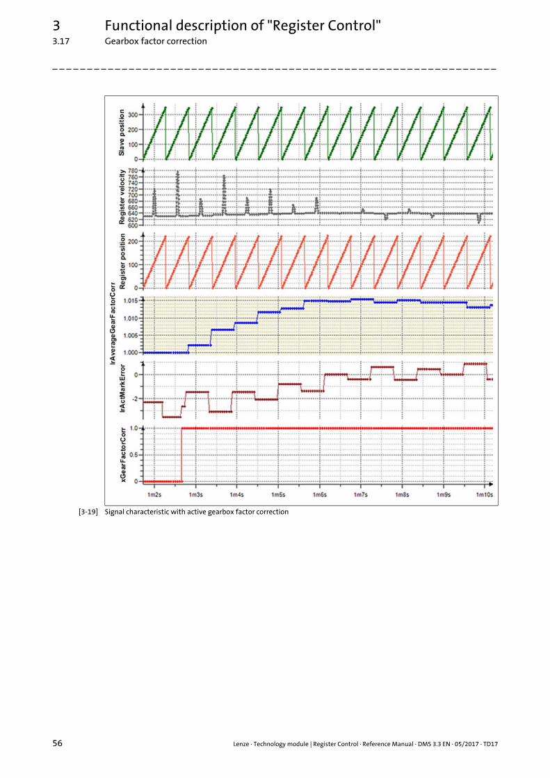
3 Functional description of "Register Control"3.17 Gearbox factor correction
56 Lenze · Technology module | Register Control · Reference Manual · DMS 3.3 EN · 05/2017 · TD17
_ _ _ _ _ _ _ _ _ _ _ _ _ _ _ _ _ _ _ _ _ _ _ _ _ _ _ _ _ _ _ _ _ _ _ _ _ _ _ _ _ _ _ _ _ _ _ _ _ _ _ _ _ _ _ _ _ _ _ _ _ _ _ _
[3-19] Signal characteristic with active gearbox factor correction
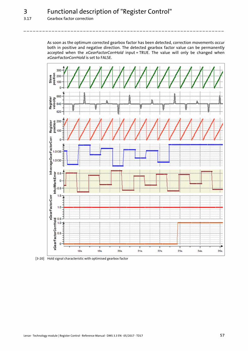
Lenze · Technology module | Register Control · Reference Manual · DMS 3.3 EN · 05/2017 · TD17 57
3 Functional description of "Register Control"3.17 Gearbox factor correction
_ _ _ _ _ _ _ _ _ _ _ _ _ _ _ _ _ _ _ _ _ _ _ _ _ _ _ _ _ _ _ _ _ _ _ _ _ _ _ _ _ _ _ _ _ _ _ _ _ _ _ _ _ _ _ _ _ _ _ _ _ _ _ _
As soon as the optimum corrected gearbox factor has been detected, correction movements occurboth in positive and negative direction. The detected gearbox factor value can be permanentlyaccepted when the xGearFactorCorrHold input = TRUE. The value will only be changed whenxGearFactorCorrHold is set to FALSE.
[3-20] Hold signal characteristic with optimised gearbox factor
3 Functional description of "Register Control"3.18 Setting up register control (Base version)
58 Lenze · Technology module | Register Control · Reference Manual · DMS 3.3 EN · 05/2017 · TD17
_ _ _ _ _ _ _ _ _ _ _ _ _ _ _ _ _ _ _ _ _ _ _ _ _ _ _ _ _ _ _ _ _ _ _ _ _ _ _ _ _ _ _ _ _ _ _ _ _ _ _ _ _ _ _ _ _ _ _ _ _ _ _ _
3.18 Setting up register control (Base version)
When the register control is activated, it is expected that the first touch probe mark is detectedwhen the register has reached the position of the touch probe sensor.
If the detected touch probe mark is located at a different position within the register cycle, thedetected deviation (touch probe error) is compensated in the correction window of the currentregister cycle.
Example: Setting up register control (Base version)
1. Detect the distance between the touch probe sensor and the attack position of the tool (e.g. cutting blade, printheads) on the material and set it in the lrSensorToolDistance parameter.
2. Reference the slave axis.
At the position where the material meets the first touch probe mark, the position of the slave axis is set as zero position in the lrHomePosition parameter.
Homing ( 35)
3. Move the slave axis for the machine start to a position outside the material access. This means that a tool attached to the axis does not touch the material.
4. Move the material until the second touch probe mark is below the sensor.
Manual jog (jogging) ( 34)
5. Load the register position:• Set the lrLoadRegPos input = lrMarkSensorPos output.• Set the xLoadRegpos input = TRUE.• Set the xLoadRegpos input = FALSE.
6. Clutch in the slave axis to the register axis and activate the register control.
Set the xSyncPos input = TRUE.
Synchronism (SyncPos) with clutch-in/declutch mechanism ( 36)
7. When the next touch probe mark is reached (FALSE/TRUE edge at the xMarkReceived output), the calculation of the touch probe deviation starts.
At the lrActMarkError output, the current deviation between the position of the detected touch probe mark and the expected touch probe position is displayed.
8. Set the xMarkCorrection parameter = TRUE to correct the detected deviation (touch probe correction).
9. Specify position offset.
Possibly, the positioning of the touch probe sensor cannot be executed exactly in the run-up (errors of measurement). In this case, a static deviation for the tool attached to the axis can be compensated via the specification of an offset.
Position offset during synchronism ( 41)
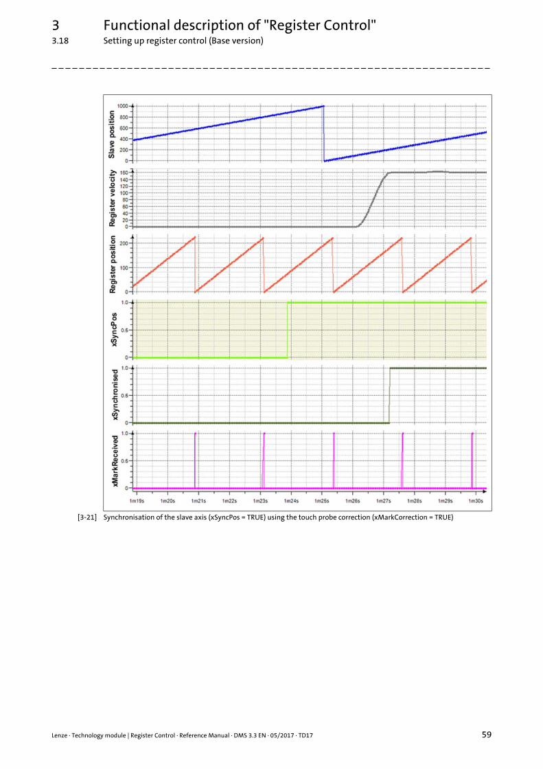
Lenze · Technology module | Register Control · Reference Manual · DMS 3.3 EN · 05/2017 · TD17 59
3 Functional description of "Register Control"3.18 Setting up register control (Base version)
_ _ _ _ _ _ _ _ _ _ _ _ _ _ _ _ _ _ _ _ _ _ _ _ _ _ _ _ _ _ _ _ _ _ _ _ _ _ _ _ _ _ _ _ _ _ _ _ _ _ _ _ _ _ _ _ _ _ _ _ _ _ _ _
[3-21] Synchronisation of the slave axis (xSyncPos = TRUE) using the touch probe correction (xMarkCorrection = TRUE)
3 Functional description of "Register Control"3.19 Setting up register control (State version)
60 Lenze · Technology module | Register Control · Reference Manual · DMS 3.3 EN · 05/2017 · TD17
_ _ _ _ _ _ _ _ _ _ _ _ _ _ _ _ _ _ _ _ _ _ _ _ _ _ _ _ _ _ _ _ _ _ _ _ _ _ _ _ _ _ _ _ _ _ _ _ _ _ _ _ _ _ _ _ _ _ _ _ _ _ _ _
3.19 Setting up register control (State version)
When the register control is activated, it is expected that the first touch probe mark is detectedwhen the register has reached the position of the touch probe sensor.
If the detected touch probe mark is located at a different position within the register cycle, thedetected position difference (touch probe error) is compensated in the correction window of thecurrent register cycle.
Example: Setting up register control (Base version)
1. Detect the distance between the touch probe sensor and the attack position of the tool (e.g. cutting blade, printheads) on the material and set it in the lrSensorToolDistance parameter.
2. Reference the slave axis.
At the position where the material meets the first touch probe mark, the position of the slave axis is set as zero position in the lrHomePosition parameter.
Homing ( 35)
3. Move the slave axis for the machine start to a position outside the material access. This means that a tool attached to the axis does not touch the material.
4. Move the material until the second touch probe mark is located approximately 10 mm in front of the detection position of the touch probe sensor.
Manual jog (jogging) ( 34)
5. Execute the teaching function.
Set the xTeachMarkWindow input = TRUE.
Teaching function ( 48)
6. Clutch in the slave axis to the register axis and activate the register control.
Set xSyncPos parameter = TRUE.Synchronism (SyncPos) with clutch-in/declutch mechanism ( 36)
7. When the next touch probe mark is reached (FALSE/TRUE edge at the xMarkReceived output), the calculation of the touch probe deviation starts.
At the lrActMarkError output, the current deviation between the position of the detected touch probe mark and the expected touch probe position is displayed.
8. Set the xMarkCorrection parameter = TRUE to correct the detected deviation (touch probe correction).
9. Specify position offset.
Possibly, the positioning of the touch probe sensor cannot be executed exactly in the run-up (errors of measurement). In this case, a static deviation for the tool attached to the axis can be compensated via the specification of an offset.
Position offset during synchronism ( 41)

Lenze · Technology module | Register Control · Reference Manual · DMS 3.3 EN · 05/2017 · TD17 61
3 Functional description of "Register Control"3.19 Setting up register control (State version)
_ _ _ _ _ _ _ _ _ _ _ _ _ _ _ _ _ _ _ _ _ _ _ _ _ _ _ _ _ _ _ _ _ _ _ _ _ _ _ _ _ _ _ _ _ _ _ _ _ _ _ _ _ _ _ _ _ _ _ _ _ _ _ _
[3-22] Synchronisation of the slave axis (xSyncPos = TRUE) using the touch probe correction (xMarkCorrection = TRUE)
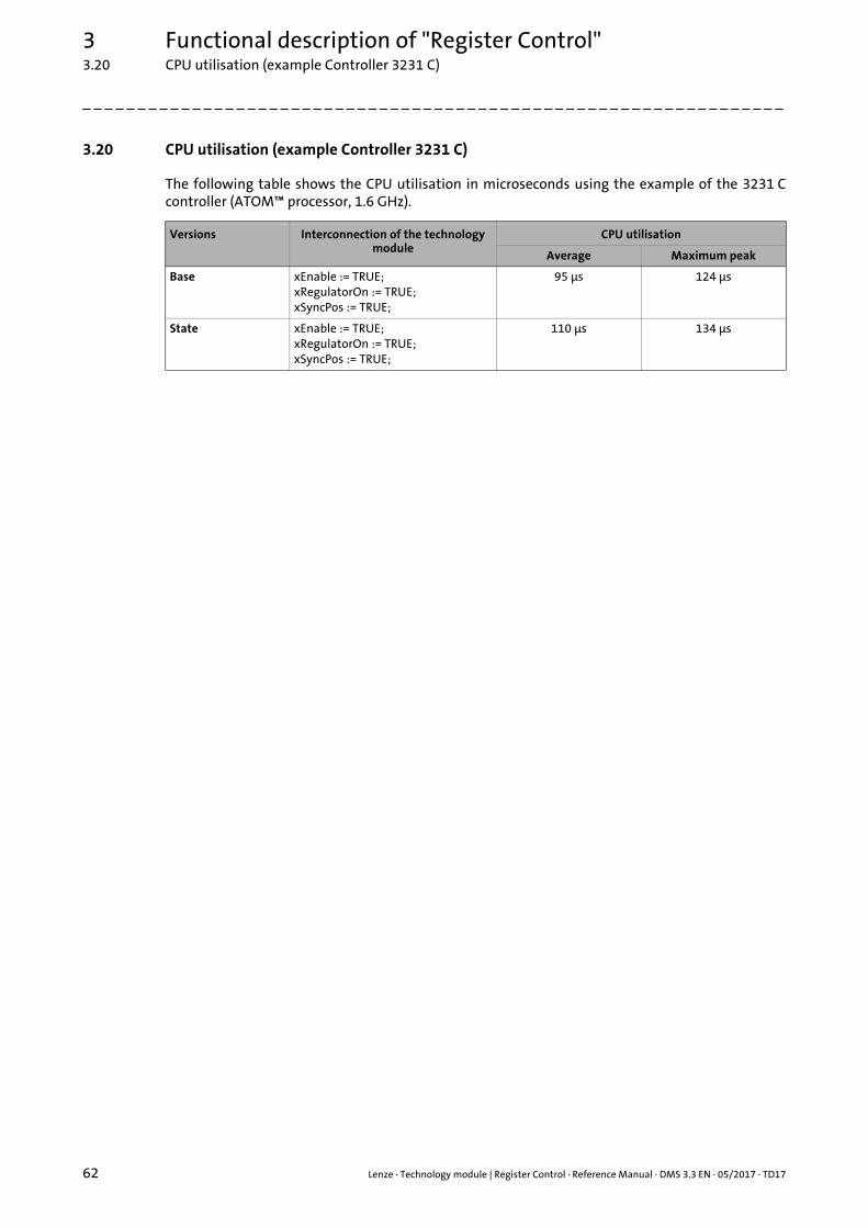
3 Functional description of "Register Control"3.20 CPU utilisation (example Controller 3231 C)
62 Lenze · Technology module | Register Control · Reference Manual · DMS 3.3 EN · 05/2017 · TD17
_ _ _ _ _ _ _ _ _ _ _ _ _ _ _ _ _ _ _ _ _ _ _ _ _ _ _ _ _ _ _ _ _ _ _ _ _ _ _ _ _ _ _ _ _ _ _ _ _ _ _ _ _ _ _ _ _ _ _ _ _ _ _ _
3.20 CPU utilisation (example Controller 3231 C)
The following table shows the CPU utilisation in microseconds using the example of the 3231 Ccontroller (ATOM™ processor, 1.6 GHz).
Versions Interconnection of the technology module
CPU utilisation
Average Maximum peak
Base xEnable := TRUE;xRegulatorOn := TRUE;xSyncPos := TRUE;
95 μs 124 μs
State xEnable := TRUE;xRegulatorOn := TRUE;xSyncPos := TRUE;
110 μs 134 μs
Lenze · Technology module | Register Control · Reference Manual · DMS 3.3 EN · 05/2017 · TD17 63
Index
_ _ _ _ _ _ _ _ _ _ _ _ _ _ _ _ _ _ _ _ _ _ _ _ _ _ _ _ _ _ _ _ _ _ _ _ _ _ _ _ _ _ _ _ _ _ _ _ _ _ _ _ _ _ _ _ _ _ _ _ _ _ _ _
AAccess points 33
Application notes 7
CControlled start of the axes 13
Conventions used 6
Correction window for the position of the register or axis 43
CPU utilisation (example Controller 3231 C) 62
DDirect clutching-in/declutching 37
Document history 5
EE-mail to Lenze 64
FFeedback to Lenze 64
Function block L_TT1P_RegisterControlBase/State 14
Functional description of "Register Control" 10
GGearbox factor correction 55
Gearbox factor for different clock cycles 39
HHiding marks 53
Homing 35
IInputs 15
Inputs and outputs 15
LL_TT1P_RegisterControlBase 14
L_TT1P_RegisterControlState 14
L_TT1P_scAP_RegisterControlBase 33
L_TT1P_scAP_RegisterControlState 33
L_TT1P_scPar_RegisterControlBase 20
L_TT1P_scPar_RegisterControlState 20
L_TT1P_scSF_RegisterControlBase 30
L_TT1P_scSF_RegisterControlState 30
Layout of the safety instructions 7
MManual jog (jogging) 34
Mark register 51
NNotes on how to operate the technology module 12
OOperating mode 12
Outputs 18
PParameter structure L_TT1P_scPar_RegisterControlBase/State 20
Position offset during synchronism 41
RRegister control 43
Register Control (functional description) 10
Relative clutching-in/declutching 38
SSafety instructions 7, 8
Sensor connection 45
Setting up register control (Base version) 58, 60
Signal flow diagrams 26Register Control Base version 26Register Control State version 28
Start of the axes 13
State machine 25
States 25
Structure of the access points L_TT1P_scAP_RegisterControlBase/State 33
Structure of the signal flow L_TT1P_scSF_RegisterControlBase/State 30
Synchronism (SyncPos) 36
SyncPos (synchronism) 36
TTarget group 4
Teaching function 48
Technology module functions (overview) 11
Touch probe failure detection 50
Touch probe source 43
Trimming 42
VVariable names 6
Index

64
Your opinion is important to usThese instructions were created to the best of our knowledge andbelief to give you the best possible support for handling our product.
Perhaps we have not succeeded in achieving this objective in everyrespect. If you have suggestions for improvement, please e-mail usto:
Thank you very much for your support.
Your Lenze documentation team

L
Technology module | Register Control · Reference Manual · SHGTMRegControl · 13531742 · DMS 3.3 EN · 05/2017 · TD17
Lenze Automation GmbHPostfach 10 13 52, 31763 HamelnHans-Lenze-Straße 1, 31855 AerzenGERMANYHR Hannover B 205381
+49 5154 82-0 +49 5154 82-2800 [email protected] www.lenze.com
ServiceLenze Service GmbHBreslauer Straße 3, 32699 ExtertalGERMANY
008000 24 46877 (24 h helpline) +49 5154 82-1112 [email protected]