Embed Size (px)
Citation preview
Dell Global Solutions Engineering
Revision: A00
July 2013
Reference Architecture for Active System
1000 with Microsoft Hyper-V
Release 1.1 for Dell PowerEdge Blade Servers, Dell Networking Switches, Dell Compellent Storage Center, and Dell Active System Manager
Reference Architecture for Active System 1000 with Microsoft Hyper-V
Dell Inc. ii
This document is for informational purposes only and may contain typographical errors and
technical inaccuracies. The content is provided as is, without express or implied warranties of any
kind.
© 2013 Dell Inc. All rights reserved. Dell and its affiliates cannot be responsible for errors or omissions
in typography or photography. Dell, the Dell logo, Compellent, OpenManage, KACE, EqualLogic,
PowerVault, and PowerEdge are trademarks of Dell Inc. Intel and Xeon are registered trademarks of
Intel Corporation in the U.S. and other countries. Microsoft, Windows, Hyper-V, Active Directory, and
Windows Server are either trademarks or registered trademarks of Microsoft Corporation in the United
States and/or other countries. VMware and vSphere are registered trademarks or trademarks of
VMware, Inc. in the United States and/or other jurisdictions. Linux is the registered trademark of Linus
Torvalds in the U. S. and other countries. Other trademarks and trade names may be used in this
document to refer to either the entities claiming the marks and names or their products. Dell disclaims
proprietary interest in the marks and names of others.
July 2013| Rev A00
Reference Architecture for Active System 1000 with Microsoft Hyper-V
Dell Inc. iii
Revision History
Revision Description Date
A00 Initial Version July 2013
Reference Architecture for Active System 1000 with Microsoft Hyper-V
Dell Inc. iv
Table of contents 1 Introduction ........................................................................................................... 1
2 Audience............................................................................................................... 1
3 Solution Overview ................................................................................................... 2
3.1 Microsoft Windows Server 2012 ............................................................................. 4
3.2 Microsoft System Center 2012 SP1 ......................................................................... 4
3.3 Dell Active System Manager ................................................................................. 5
3.4 OpenManage Essentials ....................................................................................... 5
3.5 Dell PowerEdge Blade Servers .............................................................................. 5
3.6 Dell Networking S4810 Switches ............................................................................ 6
3.7 Dell PowerEdge M I/O Aggregator .......................................................................... 7
3.8 Dell Networking MXL 10/40GbE Switch .................................................................... 7
3.9 Dell Networking S55 Switch ................................................................................. 8
3.10 Brocade 6510 ................................................................................................... 8
3.11 Dell 8/4 Gbps FC SAN Module ............................................................................... 8
3.12 Dell Compellent SC8000 Storage Center .................................................................. 8
3.13 Dell PowerEdge R620 Management Server ................................................................ 9
4 Design Principles ..................................................................................................... 9
5 Prerequisites and Datacenter Planning ........................................................................ 10
6 Architecture ........................................................................................................ 11
6.1 Dell Blade Network Architecture ......................................................................... 12
6.2 Server / Blade Network Connectivity .................................................................... 12
6.3 Server / Blade Storage Connectivity ..................................................................... 16
6.4 Server /Blade HA and Redundancy ....................................................................... 16
6.5 Storage Architecture ....................................................................................... 16
7 Management Infrastructure ...................................................................................... 23
8 Connecting Active System 1000 to Datacenter Network .................................................... 25
8.1 Connecting the S55 OOB switch to Datacenter Network ............................................. 25
8.2 Connecting to a Dell Networking Datacenter Network ............................................... 26
8.3 Connecting to a Cisco Nexus Datacenter Network .................................................... 27
9 Scalability ........................................................................................................... 28
10 Delivery Model .................................................................................................. 28
11 Additional Supported Configurations ....................................................................... 32
11.1 Dell Networking S5000 as LAN Top of Rack Switch .................................................... 32
11.2 Cisco Nexus 5548 as LAN Top of Rack Switch .......................................................... 34
Reference Architecture for Active System 1000 with Microsoft Hyper-V
Dell Inc. v
12 Reference ........................................................................................................ 35
12.1 Dell Active System Manager ............................................................................... 35
12.2 Dell Active Infrastructure Wiki ........................................................................... 35
12.3 Dell PowerEdge Server Documentation and Hardware/Software Updates ........................ 35
12.4 Dell Virtualization Documentation ....................................................................... 35
12.5 Microsoft® Hyper-V Documentation ..................................................................... 35
12.6 Microsoft® Management Software ....................................................................... 35
12.7 Microsoft® Roles and Features ........................................................................... 36
Reference Architecture for Active System 1000 with Microsoft Hyper-V
Dell Inc. vi
Figures Figure 1: Overview of Dell Blade Servers, Dell Networking Switches, Brocade Fibre Channel Switches,
Dell Compellent Storage, and Microsoft Hyper-V .............................................................. 2
Figure 2: Dell Blade Servers, Dell Networking Switches, Brocade Fibre Channel Switches, Dell
Compellent Storage ................................................................................................. 3
Figure 3: Network Topology (Logical View) with optional 2nd Chassis ........................................ 11
Figure 4: Dell Active System Blade LAN Connectivity Overview ................................................ 13
Figure 5: NPAR and VLAN Configuration on a PowerEdge M620 Blade Server ................................ 14
Figure 6: NPAR and VLAN Configuration on a PowerEdge R620 Management Server ........................ 14
Figure 7: Active System SAN Connectivity Overview .............................................................. 17
Figure 8: SAN's FC Network and Zoning .............................................................................. 21
Figure 9: Compellent Snapshot Consistency ........................................................................ 22
Figure 10: Management Architecture ................................................................................ 24
Figure 11: Connectivity of management components. ........................................................... 25
Figure 12: S55 Connectivity to Datacenter OOB Network (Default Option) ................................... 26
Figure 13: Alternative OOB Connectivity - S55 Switch to S4810 Switches ..................................... 26
Figure 14: Active System 1000m connectivity to Dell Networking Z9000 Switch ............................ 27
Figure 15: Active System 1000m connectivity to Cisco Nexus 5548 ............................................ 27
Figure 16: Active System 1000m Rack and Component Overview .............................................. 29
Figure 17: Active System 1000m Maximum 2 Rack Component Overview ..................................... 30
Figure 18: Active System 1000m Configuration for additional storage requirements: Rack Overview ... 31
Figure 19: Active System 1000m using S5000 as ToR Switch ..................................................... 33
Figure 20: Active System 1000m using Cisco Nexus 5548 as ToR Switch ...................................... 34
Tables
Table 1: Component Logical Groups ................................................................................... 4
Table 2: Traffic Description ........................................................................................... 15
Table 3: Sample VLAN and subnet configuration .................................................................. 15
Table 4: CSV Limits ..................................................................................................... 19
Reference Architecture for Active System 1000 with Microsoft Hyper-V
Dell Inc. 1
1 Introduction Dell™ Active Infrastructure is a family of converged infrastructure solutions that combine servers,
storage, networking, and infrastructure management into an integrated and optimized system that
provides general purpose virtualized resource pools. Active Infrastructure leverages Dell innovations
including unified management (Active System Manager), LAN & SAN fabrics, and modular server
architecture for the ultimate infrastructure solution. Active Infrastructure helps IT rapidly respond to
dynamic business demands, maximize data center efficiency, and strengthen IT service quality.
The Active System 1000 solution, a member of Dell Active Infrastructure family, is an enterprise
infrastructure solution that has been designed and validated by Dell™ Engineering. It is available
racked, cabled, and delivered to your site, to speed deployment. Dell Services will deploy and
configure the solution tailored for business needs and ready to be integrated into your datacenter.
Active System 1000 is offered in configurations with either VMware® vSphere™ or Microsoft® Windows
Server® 2012 with Hyper-V® role enabled Hypervisors. The VMware vSphere solution is the Active
System 1000v and the Microsoft Hyper-V solution is the Active System 1000m. This document will
define the Reference Architecture for Active System 1000m.
The architecture defined in this document includes DellTM PowerEdgeTM M620 blade servers, Dell
Compellent™ Storage, Dell Networking switches & Cisco™ network switches, Brocade Fibre Channel
switches, Microsoft Windows Server 2012 Datacenter Edition with Hyper-V Role enabled and two Dell
PowerEdge R620 servers that manage the solution by hosting Dell management tools, Microsoft System
Center 2012 SP1 System Center Virtual Machine Manager and optionally other System Center 2012 SP1
components. Dell management tools include Dell Active System Manager, Compellent Enterprise
Manager, and Dell OpenManage™ Essentials.
2 Audience This document provides an overview of the Active System solution. Readers, including CTOs and IT
managers, can use this document to understand the overview and scope of the solution. IT
administrators and managers can use this document to understand the solution architecture.
Reference Architecture for Active System 1000 with Microsoft Hyper-V
Dell Inc. 2
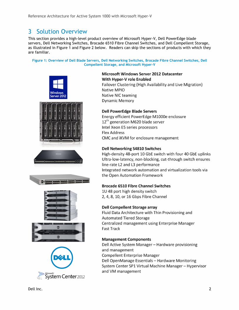
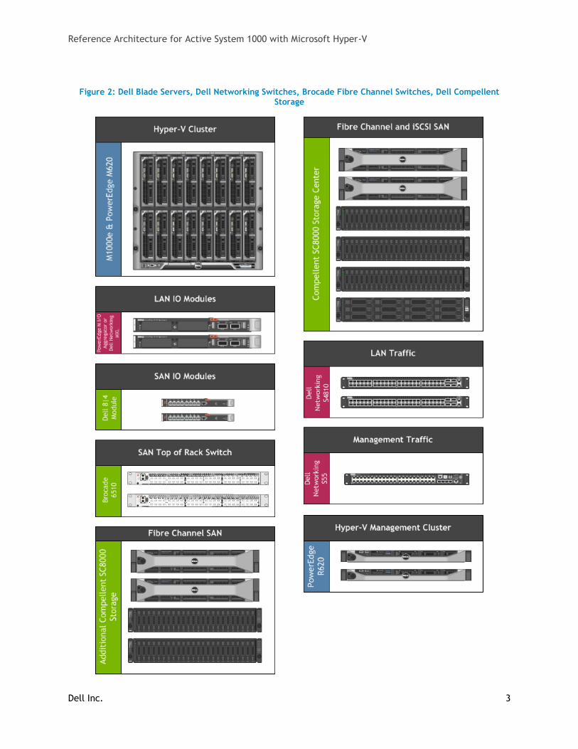
3 Solution Overview This section provides a high-level product overview of Microsoft Hyper-V, Dell PowerEdge blade servers, Dell Networking Switches, Brocade 6510 Fibre Channel Switches, and Dell Compellent Storage, as illustrated in Figure 1 and Figure 2 below. Readers can skip the sections of products with which they are familiar.
Figure 1: Overview of Dell Blade Servers, Dell Networking Switches, Brocade Fibre Channel Switches, Dell Compellent Storage, and Microsoft Hyper-V
Reference Architecture for Active System 1000 with Microsoft Hyper-V
Dell Inc. 3
Figure 2: Dell Blade Servers, Dell Networking Switches, Brocade Fibre Channel Switches, Dell Compellent Storage
Reference Architecture for Active System 1000 with Microsoft Hyper-V
Dell Inc. 4
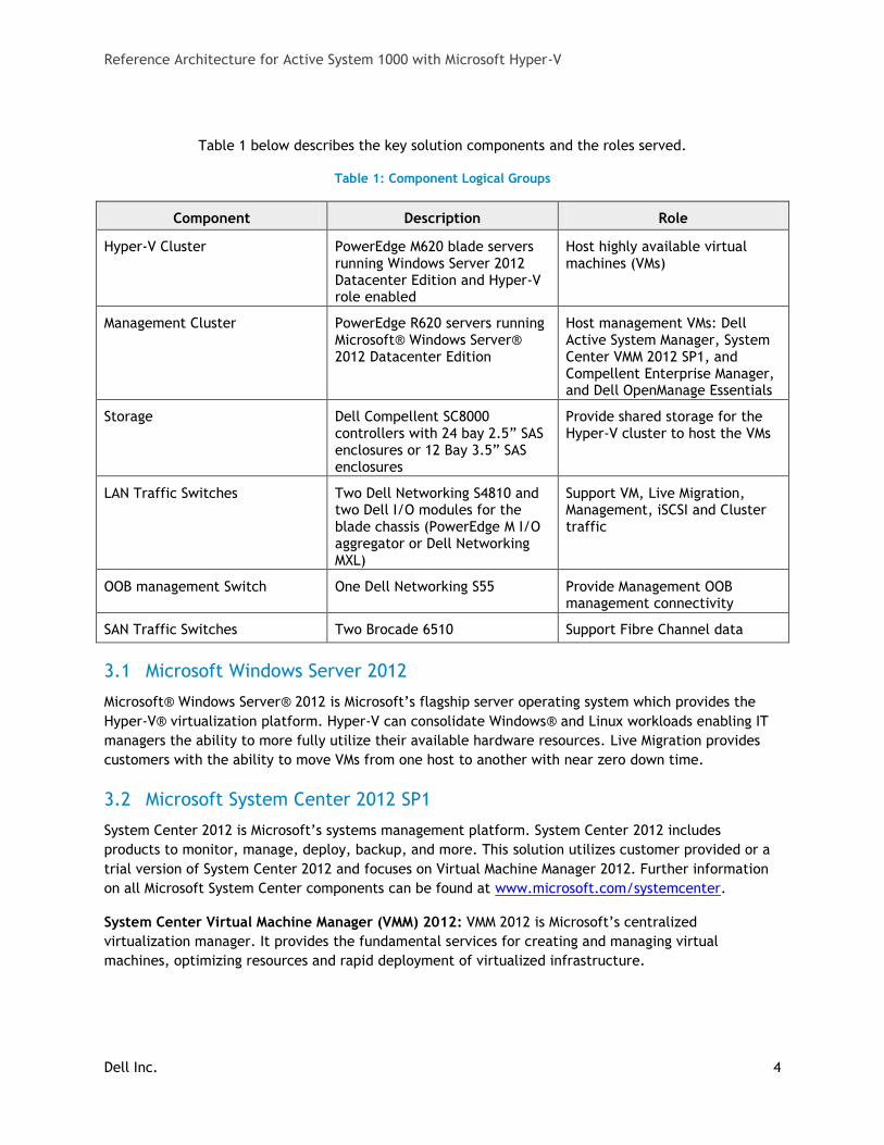
Table 1 below describes the key solution components and the roles served.
Table 1: Component Logical Groups
Component Description Role
Hyper-V Cluster PowerEdge M620 blade servers running Windows Server 2012 Datacenter Edition and Hyper-V role enabled
Host highly available virtual machines (VMs)
Management Cluster PowerEdge R620 servers running Microsoft® Windows Server® 2012 Datacenter Edition
Host management VMs: Dell Active System Manager, System Center VMM 2012 SP1, and Compellent Enterprise Manager, and Dell OpenManage Essentials
Storage Dell Compellent SC8000 controllers with 24 bay 2.5” SAS enclosures or 12 Bay 3.5” SAS enclosures
Provide shared storage for the Hyper-V cluster to host the VMs
LAN Traffic Switches Two Dell Networking S4810 and two Dell I/O modules for the blade chassis (PowerEdge M I/O aggregator or Dell Networking MXL)
Support VM, Live Migration, Management, iSCSI and Cluster traffic
OOB management Switch One Dell Networking S55 Provide Management OOB management connectivity
SAN Traffic Switches Two Brocade 6510 Support Fibre Channel data
3.1 Microsoft Windows Server 2012
Microsoft® Windows Server® 2012 is Microsoft’s flagship server operating system which provides the
Hyper-V® virtualization platform. Hyper-V can consolidate Windows® and Linux workloads enabling IT
managers the ability to more fully utilize their available hardware resources. Live Migration provides
customers with the ability to move VMs from one host to another with near zero down time.
3.2 Microsoft System Center 2012 SP1
System Center 2012 is Microsoft’s systems management platform. System Center 2012 includes
products to monitor, manage, deploy, backup, and more. This solution utilizes customer provided or a
trial version of System Center 2012 and focuses on Virtual Machine Manager 2012. Further information
on all Microsoft System Center components can be found at www.microsoft.com/systemcenter.
System Center Virtual Machine Manager (VMM) 2012: VMM 2012 is Microsoft’s centralized
virtualization manager. It provides the fundamental services for creating and managing virtual
machines, optimizing resources and rapid deployment of virtualized infrastructure.
Reference Architecture for Active System 1000 with Microsoft Hyper-V
Dell Inc. 5
3.3 Dell Active System Manager
Active System Manager sits at the center of Active System, and simplifies infrastructure configuration,
collapses management tools, and drives automation and consistency. Through capabilities such as
template-based provisioning, automated configuration, and infrastructure lifecycle management,
Active System Manager enables IT to respond rapidly to business needs, maximize data center
efficiency, and strengthen quality of IT service delivery.
The software enables a cloud like environment, and supports pre-built provisioning templates and
custom orchestrated workflows for a wide range of physical or virtual environments. Use and features
of the Dell Active System Manager will be described in more detail in subsequent sections of this
document. Additional detail can also be found on the Dell website at: Dell Active System Manager.
3.4 OpenManage Essentials
The Dell OpenManage™ Essentials Console provides a single, easy-to-use, one-to-many interface
through which to manage resources in multivendor operating system and hypervisor environments. It
automates basic repetitive hardware management tasks — like discovery, monitoring, and updates —
for Dell servers, storage, and network systems. OME employs the embedded management of
PowerEdge™ servers — Integrated Dell Remote Access Controller 7 (iDRAC7) with Lifecycle Controller —
to enable agent-free remote management and monitoring of server hardware components like storage,
networking, processors, and memory.
OpenManage Essentials helps you maximize IT performance and uptime with capabilities like:
Automated discovery, inventory, and monitoring of Dell PowerEdge™ servers, EqualLogic™
and PowerVault™ storage, and PowerConnect™ switches
Agent-free server monitoring as well as BIOS, firmware and driver updates for Dell PowerEdge
servers, blade systems, and internal storage
Control of PowerEdge servers within Windows®, Linux®, VMware®, and Hyper-V®
environments
Interface with additional optional Dell systems management solutions including:
o Repository Manager to facilitate and secure precise control of system updates
o KACE® K1000 Appliance service desk to provide actionable email alerts describing the
status of Dell servers, storage, and switches
o Dell ProSupport™ phone home services for your data center resources
For more information on OpenManage Essentials, see Dell.com/openmanageessentials.
3.5 Dell PowerEdge Blade Servers
Blade Modular Enclosure: The Dell PowerEdge M1000e is a high-density, energy-efficient blade chassis
that supports up to sixteen half-height blade servers, or eight full-height blade servers, and six I/O
modules. A high-speed passive mid-plane connects the server modules to the I/O modules,
management, and power in the rear of the chassis. The enclosure includes a flip-out LCD screen (for
local configuration), six hot-pluggable/redundant power supplies, and nine hot-pluggable N+1
redundant fan modules.
Reference Architecture for Active System 1000 with Microsoft Hyper-V
Dell Inc. 6
Blade Servers: The Dell PowerEdge M1000e Blade Server Chassis supports the Dell PowerEdge M620
blade servers based on Intel® Xeon® E5 series processors. Dell’s embedded management houses the
tools and enablement pieces for management directly on the server, allowing administrators to
perform a complete set of provisioning functions from a single, intuitive interface. Zero-media low-
touch deployment capabilities enable IT administrators to provision workloads in an efficient, secure,
and user-friendly manner. The enclosure supports all Dell PowerEdge 12th generation blade servers, but
the PowerEdge M620 was selected as the optimum blade server for this solution.
I/O Modules: The enclosure provides three redundant fabrics using six I/O modules. The modules can
be populated with Ethernet switches, Fibre Channel (FC), and IO Aggregator modules.
Chassis Management: The Dell PowerEdge M1000e has integrated management through a redundant
Chassis Management Controller (CMC) module for enclosure management and integrated keyboard,
video, and mouse (iKVM) modules. Through the CMC, the enclosure supports FlexAddress Plus
technology which enables the blade enclosure to lock the World Wide Names (WWN) of the FC
controllers and Media Access Control (MAC) addresses of the Ethernet controllers to specific blade
slots. This enables seamless swapping or upgrading of blade servers with Ethernet and FC controllers
without affecting the LAN or SAN configuration.
Embedded Management with Dell’s Lifecycle Controller: The Lifecycle Controller is the engine for
advanced embedded management and is delivered as part of iDRAC7 Enterprise in Dell PowerEdge 12th
generation blade servers. Embedded management includes:
Unified Server Configurator (USC) aims at local 1-to-1 deployment via a graphical user interface
(GUI) for operating system install, updates, configuration, and for performing diagnostics on
single, local servers. This eliminates the need for multiple option ROMs for hardware
configuration.
Remote Services are standards-based interfaces that enable consoles to integrate, for example,
bare-metal provisioning and one-to-many OS deployments, for servers located remotely. Dell’s
Lifecycle Controller takes advantage of the capabilities of both USC and Remote Services to
deliver significant advancement and simplification of server deployment.
Lifecycle Controller Serviceability aims at simplifying server re-provisioning and/or replacing
failed parts and thus reduces maintenance downtime.
For more information on Dell Lifecycle Controllers and blade servers, see
http://content.dell.com/us/en/enterprise/dcsm-embedded-management and Dell.com/blades.
3.6 Dell Networking S4810 Switches
The Dell Networking S-Series S4810 is an ultra-low-latency 10/40 GbE Top-of-Rack (ToR) switch
purpose-built for applications in high-performance data center and computing environments.
Leveraging a non-blocking, cut-through switching architecture, the S4810 switch delivers line-rate L2
and L3 forwarding capacity with ultra-low latency to maximize network performance. The compact
S4810 switch design provides industry leading density of 48 dual-speed 1/10 GbE (SFP+) ports as well as
four 40 GbE QSFP+ uplinks to conserve valuable rack space and simplify the migration to 40 Gbps in the
data center core. Each 40 GbE QSFP+ uplink can support four 10 GbE ports with a breakout cable.
Powerful Quality of Service (QoS) features are coupled with Data Center Bridging (DCB) support,
making the S4810 switch ideally suited for converged storage environments. In addition, the S4810
switch incorporates multiple architectural features that optimize data center network flexibility,
Reference Architecture for Active System 1000 with Microsoft Hyper-V
Dell Inc. 7
efficiency, and availability, including Dell Networking’s Virtual Line Trunking, reversible front-to-back
or back-to-front airflow for hot/cold aisle environments, and redundant, hot-swappable power supplies
and fans. For more information on Dell Networking switches, see http://www.dell.com/networking.
3.7 Dell PowerEdge M I/O Aggregator
The Dell PowerEdge M I/O Aggregator (IOA) is a flexible 1/10GbE aggregation device that is automated
and pre-configured for easy deployment into converged iSCSI and FCoE networks. The key feature of
the PowerEdge M I/O Aggregator is that all VLANs are allowed as a default setting. This allows the top-
of-rack (ToR) managed switch to perform all VLAN management related tasks. The external ports of the
PowerEdge M I/O Aggregator are automatically all part of a single link aggregation group (LAG), and
thus there is no need for Spanning-tree. The PowerEdge M I/O Aggregator can use Data Center Bridging
(DCB) and Data Center Bridging Exchange (DCBX) to support converged network architecture.
The PowerEdge M I/O Aggregator provides connectivity to the Converged Network Adapters (CNA)
internally and externally to upstream network devices. Internally the PowerEdge M I/O Aggregator
provides thirty-two (32) connections. The connections are 10 Gigabit Ethernet connections for basic
Ethernet traffic, iSCSI storage traffic, or FCoE storage traffic. In a typical PowerEdge M1000e
configuration with 16 half-height blade server ports, 1-16 are used and 17-32 are disabled. If quad port
CNA/Network adapters or quarter-height blade servers are used, then ports 17-32 will be enabled.
The PowerEdge M I/O Aggregator includes two integrated 40Gb Ethernet ports on the base module.
These ports can be used in a default configuration with a 4 X 10Gb breakout cable to provide four 10Gb
links for network traffic. Alternatively these ports can be used as 40Gb links for stacking. The Dell
PowerEdge M I/O Aggregator also supports three different types of add-in expansion modules, which
are called FlexIO Expansion modules. The modules available are: 4-port 10Gbase-T FlexIO module, 4-
port 10G SFP+ FlexIO module, and the 2-port 40G QSFP+ FlexIO module.
The PowerEdge M I/O Aggregator modules can be managed through the PowerEdge M1000e Chassis
Management Controller (CMC) GUI. Also, the out-of-band management port on the PowerEdge M I/O
Aggregator is reached by connection through the CMC’s management port. This one management port
on the CMC allows for management connections to all I/O modules within the PowerEdge M1000e
chassis.
For more information on Dell PowerEdge M I/O Aggregator, see
http://www.dell.com/us/business/p/poweredge-m-io-aggregator/pd.
3.8 Dell Networking MXL 10/40GbE Switch
The MXL switch provides 1/10/40GbE. The switch supports 32 internal 1/10GbE ports, as well as two
fixed 40GbE QSFP+ ports and offers two bays for optional FlexIO modules. To ensure room to grow,
uplinks via the FlexIO modules can be added or swapped as needed in the future. Choose from 2-port
QSFP+, 4-port SFP+ or 4-port 10GBASE-T FlexIO modules to expand and aggregate (bi-directional)
bandwidth up to 160 Gigabit per second. The MXL switch provides the flexibility to mix and match the
FlexIO module types.
Like the M I/OA above, the MXL switch includes two integrated 40Gb Ethernet ports on the base
module. These ports are used in a default configuration with a 4 X 10Gb breakout cable to provide four
10Gb links for network traffic. Alternatively these ports can be used as 40Gb links for stacking. The
MXL Switch provides stacking capability for up to 6 interconnected blade switches allowing both
Reference Architecture for Active System 1000 with Microsoft Hyper-V
Dell Inc. 8
stacking across chassis and local switching of traffic within the chassis. For more information, see
http://www.dell.com/us/business/p/force10-mxl-blade/pd.
3.9 Dell Networking S55 Switch
The Dell Networking S-Series S55 1/10 GbE ToR switch is designed for high-performance data center
applications. The S55 switch leverages a non-blocking architecture that delivers line-rate, low-latency
L2 and L3 switching to eliminate network bottlenecks. The high-density S55 switch design provides 48
GbE access ports with up to four modular 10GbE uplinks in 1-RU to conserve valuable rack space. The
S55 switch incorporates multiple architectural features that optimize data center network efficiency
and reliability, including reversible front-to-back or back-to-front airflow for hot/cold aisle
environments and redundant, hot-swappable power supplies and fans. For more information on Dell
Networking switches, see http://www.dell.com/networking.
3.10 Brocade 6510
The Brocade 6510 switch is a high density FC switch providing 48 ports in a 1U form factor. The 6510
switch includes redundant power supplies and fans making it well suited to the high availability needs
of virtualization infrastructures.
For more information on Brocade 6510 Fibre Channel Switches, see Dell.com/brocade.
3.11 Dell 8/4 Gbps FC SAN Module
The Dell 8/4 Gbps FC SAN Module is a 24-port FC module with eight external ports and 16 internal ports
that installs in a Dell PowerEdge M1000e Blade Enclosure. Built on industry-standard N_Port ID
Virtualization (NPIV) technology, the module eliminates the traditional challenges of heterogeneous
switch-to-switch interoperability and can non-disruptively connect Dell blades to NPIV-enabled
FC SANs, including Brocade, Cisco, McData, and others. The Dell 8/4 Gbps FC SAN Module eliminates
incremental switch management and configuration by presenting FC connections as a logical device
(rather than switch domains) to the SAN fabric. The module enables the benefits of port aggregation,
failover, and redundancy without the complexities of additional SAN switches or additional switch
domains.
For more information on Dell 8/4 Gbps FC SAN Module, see http://www.dell.com/us/enterprise/p/fc-
san/pd.
3.12 Dell Compellent SC8000 Storage Center
The SC8000 is a 2U Storage Center controller built on the Dell 12th generation PowerEdge™ server
platform with a custom configuration to support the needs of the enterprise storage controller. The
SC8000 offers increased density, exceptional processing power, greater memory, faster PCIe Gen3 IO
bus, improved diagnostics capability with the Integrated Dell Remote Access Controller (iDRAC), and
exceptional power efficiency with Energy Star Platinum rated dual hot-swappable power supplies using
Fresh Air™ technology. The SC8000 IO expansion consists of 7 PCIe Gen 3 (double the bandwidth of Gen
2) capable slots: four full-height and three low-profile slots. One full-height slot contains the controller
cache card. The remaining three full-height and three low-profile slots are reserved for back-end and
front-end IO expansion. The SC8000 controllers are connected to SC200/220 SAS enclosures in daisy
chain loop. The SC200/220 are 2U 6Gb SAS enclosures. The SC200 supports up to twelve (12) 3.5” disk
Reference Architecture for Active System 1000 with Microsoft Hyper-V
Dell Inc. 9
drives and SC220 supports up to twenty four (24) 2.5” disk drives. Supported drives can include a mix
of drive speed and capacity in any slot within the enclosure.
For more information on Dell Compellent, see Dell.com/Compellent.
Features of the Dell Compellent SC8000 Storage Array include:
Fluid Data Architecture – Storage is managed at the most granular level with built-in system
intelligence to enable the dynamic flow of enterprise data.
Storage Virtualization – Storage is virtualized at the disk level to create a flexible pool of
storage resources shared by all servers all the time.
Thin Provisioning – Allocation is completely separated from utilization so any size volume can
be created at any time, yet capacity is only consumed when data is written.
Automated Tiered Storage – Data dynamically cascades from tier to tier according to actual
usage, freeing up high-performance drives for mission-critical applications.
Space-efficient Replays – Continuous snapshots only capture changes in data for real-time
protection with instant recovery to any point in time.
Thin Replication – Data is replicated between local and remote sites using space-efficient
snapshots and native IP or FC connectivity, eliminating the need for high-speed data links or
identical system configurations.
Unified Storage Resource Management – All storage resources are managed through a single
point-and-click interface, providing a complete view of the entire storage environment.
Open, Agile Hardware Platform – Storage is designed for persistence, not obsolescence,
leveraging a single modular hardware platform coupled with technology independence.
For more information on Dell Compellent see, Dell.com/Compellent. Contact your Dell sales
representative for more information on Compellent storage configurations and sizing guidelines.
3.13 Dell PowerEdge R620 Management Server
The Dell PowerEdge R620 management server uses Intel® Xeon® E5-2600 series processors in a 1U rack
mount form factor. These servers support up to ten 2.5” drives and provide the option for an LCD
located in the front of the server for system health monitoring, alerting, and basic management
configuration. An AC power meter and ambient temperature thermometer are built into the server,
which can be monitored on this display without any software tools. The server features two CPU
sockets and 24 memory DIMM slots supporting 2, 4, 8, 16 or 32GB DIMMs.
Energy-efficient design features include power-supply units sized appropriately for system
requirements, innovative system-level design efficiency, policy-driven power and thermal
management, and highly efficient standards-based Energy Smart components. For more information,
see the PowerEdge R620 guides at Dell.com/PowerEdge.
4 Design Principles This section covers the design principles, requirements, and solution capabilities incorporated in the
Active System solution architecture.
Optimal Hardware Configuration for Virtualization - The solution is designed with an optimal
hardware configuration to support virtualization. Each blade server is configured with sufficient
memory and network adapters required for virtualization.
Reference Architecture for Active System 1000 with Microsoft Hyper-V
Dell Inc. 10
Redundancy with No Single Point of Failure - The system is designed to mitigate failure
points. Network redundancy for the mission critical components is achieved with redundant
network interface controllers (NICs) and redundant switches. NIC teaming for LAN and MPIO for
SAN are used to provide failover across the redundant network interfaces. For FC storage,
redundancy is achieved with multiple HBA ports, FC switches, and storage controllers. For
network traffic, NIC ports are teamed in such a way that they avoid any single point of failure.
Hyper-V High Availability (HA) is provided by Windows Server 2012 Failover Clustering. The
solution also includes redundant power supplies connected to separate PDUs. Out-of-Band
(OOB) Management is not architected with this level of redundancy since mission critical
workloads will continue to operate in the event of an OOB management failure.
Flexible Configurations - Active System 1000m is pre-configured to suit most customer needs
for a virtualized infrastructure. The solution also supports additional options, such as
configuring racks, server processors, server memory, and storage, based on customer needs.
Racked, Cabled and Ready to be Deployed - Active System is available racked, cabled, and
delivered to the customer site ready for deployment. Where components are unable to ship in
the rack, they will be shipped separately and racked on site. Components are configured and
racked to optimize airflow and thermals. Based on customer needs, different rack sizes and
configurations are available to support various datacenter requirements.
5 Prerequisites and Datacenter Planning To support the architecture, the following components are required to be present in the customer
environment:
An existing 10 Gb Ethernet infrastructure with which to integrate is required.
Additional components, such as Dell Networking cables and transceivers, are needed to uplink
the solution to the customer network. The components to be added will depend on customer
networking and uplink requirements.
Active Directory® (AD) Domain Services (AD DS) – An AD DS domain must be available on the
network. The Hyper-V hosts will be joined to an existing or new domain. Cluster Services also
require AD DS. Consult with your Dell Sales and Services representatives for more details.
Domain Name Server (DNS) – DNS must be available on the management network.
Database to support SC 2012 VMM - For a list of supported databases refer to: Requirements
for System Center 2012 - Virtual Machine Manager.
o If IT Administrators wish to install VMM on the Dell PowerEdge R620 Management Server or as a VM, then a route must exist between the management server (physical or as a VM) and the database used.
o The database is assumed to have maintenance and backup configured as per the business needs of the customer.
Sufficient power and cooling to support the solution must be present. Detailed power, weight,
and cooling requirements for the datacenter are defined in the Solution Specification Guide for
Active System 1000 with Microsoft Hyper-V.
Reference Architecture for Active System 1000 with Microsoft Hyper-V
Dell Inc. 11
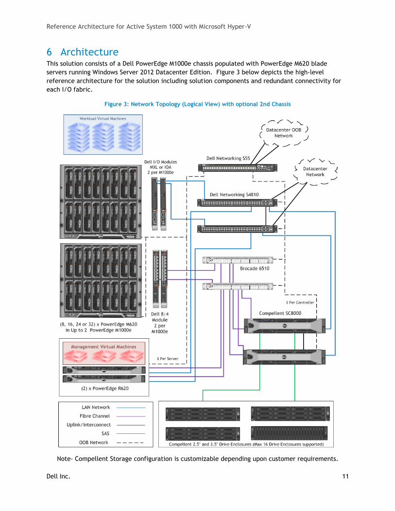
6 Architecture This solution consists of a Dell PowerEdge M1000e chassis populated with PowerEdge M620 blade
servers running Windows Server 2012 Datacenter Edition. Figure 3 below depicts the high-level
reference architecture for the solution including solution components and redundant connectivity for
each I/O fabric.
Figure 3: Network Topology (Logical View) with optional 2nd Chassis
Note- Compellent Storage configuration is customizable depending upon customer requirements.
Reference Architecture for Active System 1000 with Microsoft Hyper-V
Dell Inc. 12
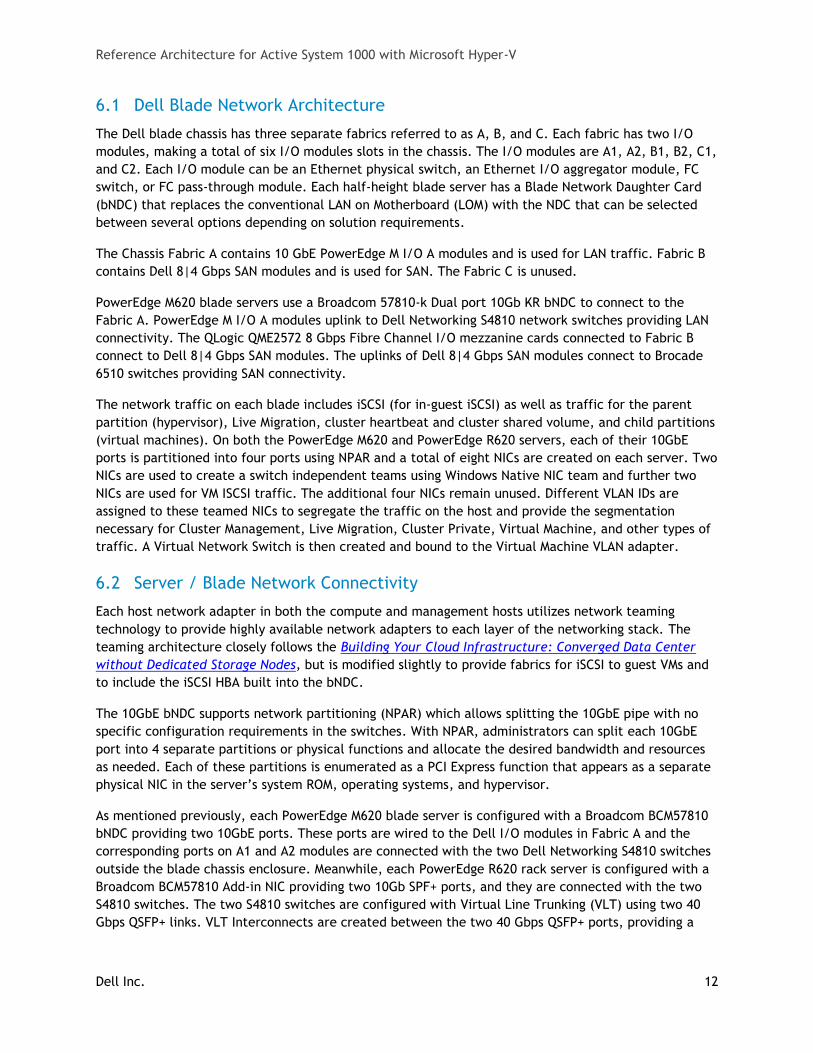
6.1 Dell Blade Network Architecture
The Dell blade chassis has three separate fabrics referred to as A, B, and C. Each fabric has two I/O
modules, making a total of six I/O modules slots in the chassis. The I/O modules are A1, A2, B1, B2, C1,
and C2. Each I/O module can be an Ethernet physical switch, an Ethernet I/O aggregator module, FC
switch, or FC pass-through module. Each half-height blade server has a Blade Network Daughter Card
(bNDC) that replaces the conventional LAN on Motherboard (LOM) with the NDC that can be selected
between several options depending on solution requirements.
The Chassis Fabric A contains 10 GbE PowerEdge M I/O A modules and is used for LAN traffic. Fabric B
contains Dell 8|4 Gbps SAN modules and is used for SAN. The Fabric C is unused.
PowerEdge M620 blade servers use a Broadcom 57810-k Dual port 10Gb KR bNDC to connect to the
Fabric A. PowerEdge M I/O A modules uplink to Dell Networking S4810 network switches providing LAN
connectivity. The QLogic QME2572 8 Gbps Fibre Channel I/O mezzanine cards connected to Fabric B
connect to Dell 8|4 Gbps SAN modules. The uplinks of Dell 8|4 Gbps SAN modules connect to Brocade
6510 switches providing SAN connectivity.
The network traffic on each blade includes iSCSI (for in-guest iSCSI) as well as traffic for the parent
partition (hypervisor), Live Migration, cluster heartbeat and cluster shared volume, and child partitions
(virtual machines). On both the PowerEdge M620 and PowerEdge R620 servers, each of their 10GbE
ports is partitioned into four ports using NPAR and a total of eight NICs are created on each server. Two
NICs are used to create a switch independent teams using Windows Native NIC team and further two
NICs are used for VM ISCSI traffic. The additional four NICs remain unused. Different VLAN IDs are
assigned to these teamed NICs to segregate the traffic on the host and provide the segmentation
necessary for Cluster Management, Live Migration, Cluster Private, Virtual Machine, and other types of
traffic. A Virtual Network Switch is then created and bound to the Virtual Machine VLAN adapter.
6.2 Server / Blade Network Connectivity
Each host network adapter in both the compute and management hosts utilizes network teaming
technology to provide highly available network adapters to each layer of the networking stack. The
teaming architecture closely follows the Building Your Cloud Infrastructure: Converged Data Center
without Dedicated Storage Nodes, but is modified slightly to provide fabrics for iSCSI to guest VMs and
to include the iSCSI HBA built into the bNDC.
The 10GbE bNDC supports network partitioning (NPAR) which allows splitting the 10GbE pipe with no
specific configuration requirements in the switches. With NPAR, administrators can split each 10GbE
port into 4 separate partitions or physical functions and allocate the desired bandwidth and resources
as needed. Each of these partitions is enumerated as a PCI Express function that appears as a separate
physical NIC in the server’s system ROM, operating systems, and hypervisor.
As mentioned previously, each PowerEdge M620 blade server is configured with a Broadcom BCM57810
bNDC providing two 10GbE ports. These ports are wired to the Dell I/O modules in Fabric A and the
corresponding ports on A1 and A2 modules are connected with the two Dell Networking S4810 switches
outside the blade chassis enclosure. Meanwhile, each PowerEdge R620 rack server is configured with a
Broadcom BCM57810 Add-in NIC providing two 10Gb SPF+ ports, and they are connected with the two
S4810 switches. The two S4810 switches are configured with Virtual Line Trunking (VLT) using two 40
Gbps QSFP+ links. VLT Interconnects are created between the two 40 Gbps QSFP+ ports, providing a
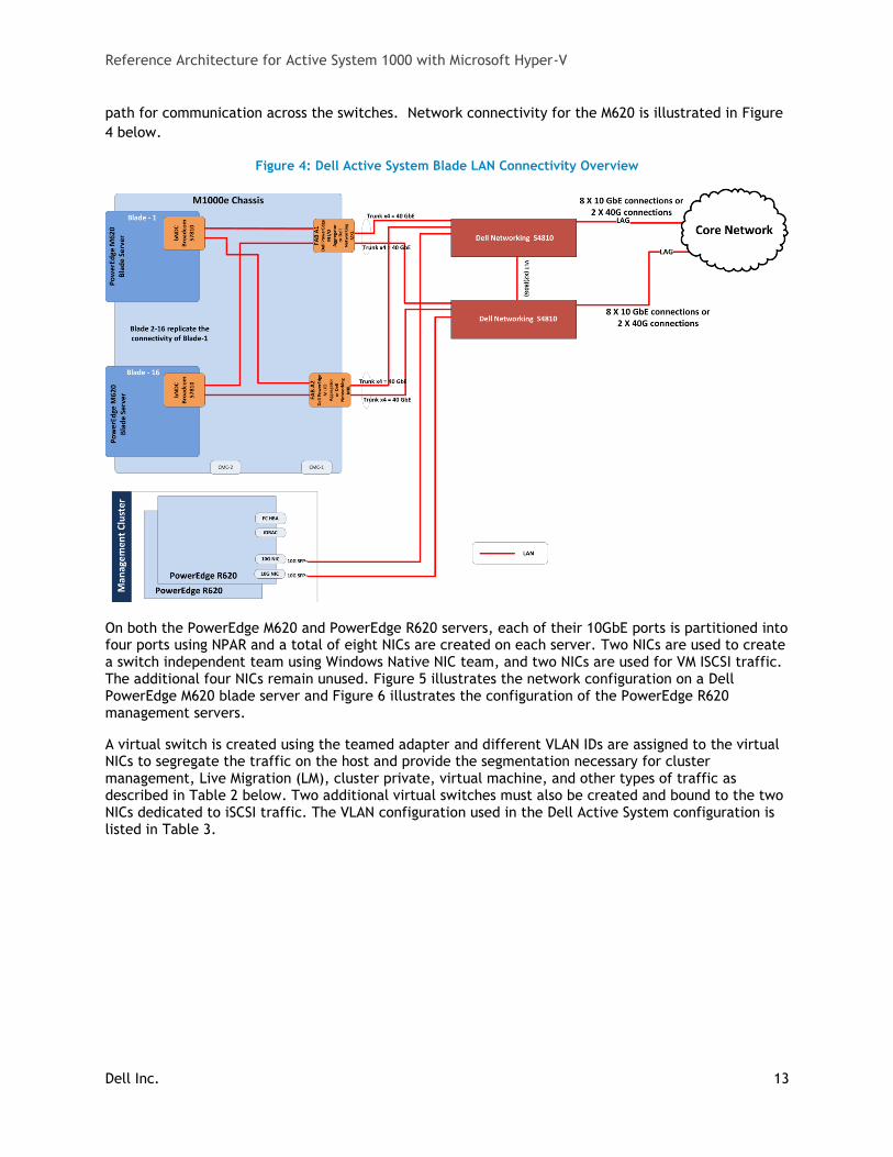
Reference Architecture for Active System 1000 with Microsoft Hyper-V
Dell Inc. 13
path for communication across the switches. Network connectivity for the M620 is illustrated in Figure
4 below.
Figure 4: Dell Active System Blade LAN Connectivity Overview
On both the PowerEdge M620 and PowerEdge R620 servers, each of their 10GbE ports is partitioned into four ports using NPAR and a total of eight NICs are created on each server. Two NICs are used to create a switch independent team using Windows Native NIC team, and two NICs are used for VM ISCSI traffic. The additional four NICs remain unused. Figure 5 illustrates the network configuration on a Dell PowerEdge M620 blade server and Figure 6 illustrates the configuration of the PowerEdge R620 management servers.
A virtual switch is created using the teamed adapter and different VLAN IDs are assigned to the virtual NICs to segregate the traffic on the host and provide the segmentation necessary for cluster management, Live Migration (LM), cluster private, virtual machine, and other types of traffic as described in Table 2 below. Two additional virtual switches must also be created and bound to the two NICs dedicated to iSCSI traffic. The VLAN configuration used in the Dell Active System configuration is listed in Table 3.
Reference Architecture for Active System 1000 with Microsoft Hyper-V
Dell Inc. 14
Figure 5: NPAR and VLAN Configuration on a PowerEdge M620 Blade Server
Figure 6: NPAR and VLAN Configuration on a PowerEdge R620 Management Server
Reference Architecture for Active System 1000 with Microsoft Hyper-V
Dell Inc. 15
Table 2: Traffic Description
Traffic Type Use
Compute Node Hypervisor (Mgmt)
Supports virtualization management traffic and communication between the host servers in the cluster.
Compute Live Migration
Supports migration of VMs between the host servers in the cluster.
Tenant VM Supports communication between the VMs hosted on the cluster and external systems.
Compute Cluster Private
Supports internal cluster network communication between the servers in the cluster.
Out-of-Band Management
Supports configuration and monitoring of the servers through the iDRAC management interface, storage arrays, and network switches.
iSCSI Data Supports iSCSI traffic between the servers and storage array(s). In addition, traffic between the arrays is supported.
Management Node Hypervisor
Supports virtualization management traffic and communication between the management servers in the cluster.
Management Cluster Private
Supports private cluster traffic for the management clusters.
Management Live Migration
Supports migration of VMs between the management servers in the cluster.
Management VM Supports the virtual machine traffic for the management virtual machines.
Table 3: Sample VLAN and subnet configuration
Traffic Type Sample VLAN
Out-of-Band Management 24
Compute Node Management 20
Compute Live Migration 21
Compute Cluster Private 22
Compute VM Network 23
Management Hypervisor 26
Management Cluster LM 27
Management Cluster Private 28
SQL Clustering 30
Management VM Network 32
iSCSI-1 25
iSCSI-2 33
Reference Architecture for Active System 1000 with Microsoft Hyper-V
Dell Inc. 16
6.3 Server / Blade Storage Connectivity
In the Active System configuration, each PowerEdge M620 and PowerEdge R620 server uses an internal
RAID controller PERC H710 and is connected to two SAS HDDs configured in a RAID-1. This RAID volume
hosts Windows Server 2012 for the hypervisor OS.
Each server also includes a dual port 8 Gbps Fibre Channel adapter for attaching to SAN volumes and
dual port 10 GbE network adapters for passing iSCSI traffic through to the guest VMs.
6.4 Server /Blade HA and Redundancy
The PowerEdge M620 blade chassis enclosure PowerEdge M1000e is designed with redundant power
supplies and redundant fans. Each PowerEdge M620 uses a PERC H710 RAID controller and two hard
drives configured in a RAID-1 which hosts the parent operating system.
The design of PowerEdge R620 servers includes high availability and redundant features such as
redundant fans and power supplies that are distributed to independent power sources. The servers also
use PERC H710 controllers with two hard disks configured with RAID-1 to prevent server crashes in the
event of single disk failures.
6.5 Storage Architecture
This section describes the storage architecture of Active System 1000m.
6.5.1 Storage Options
The Dell Active System for Enterprise Virtualization uses the Dell Compellent SC8000 for shared SAN
storage. The SC8000 provides the solution with both Fibre Channel and iSCSI front end storage
connectivity options. The Fibre Channel is used for hypervisor connectivity and provides a dedicated
SAN fabric for the storage traffic. This gives the hypervisors dedicated bandwidth to provide the VMs a
very low latency and high bandwidth option for storage connectivity. The iSCSI interfaces are added to
the Compellent SC8000 to provide an interface for the VMs to have direct access to enable in-guest
clustering.
This solution also gives an option of adding Dell Compellent storage controllers for specific
configurations which require high IOPS. These optional configurations are different from default
configurations in terms of storage only. The remaining components are unchanged in optional
configurations.
6.5.2 SAN Storage Protocols
This Dell Active System solution utilizes both Fibre Channel and iSCSI protocols. The Fibre Channel
storage, being a low-latency and ultra-high performance infrastructure, is used for the parent to
storage connectivity. The host-to-array Fibre Channel is in the 8Gbps form. For Hyper-V, iSCSI-capable
storage provides an advantage in that it is the protocol that can also be utilized by Hyper-V guest
virtual machines for guest clustering. This requires that VM storage traffic and other network traffic
flow over the same interface; however this contention is mitigated through the use of VLANs and NPAR
on the network adapter.
Reference Architecture for Active System 1000 with Microsoft Hyper-V
Dell Inc. 17
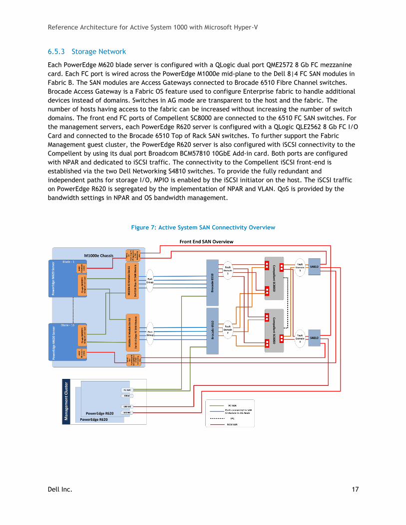
6.5.3 Storage Network
Each PowerEdge M620 blade server is configured with a QLogic dual port QME2572 8 Gb FC mezzanine
card. Each FC port is wired across the PowerEdge M1000e mid-plane to the Dell 8|4 FC SAN modules in
Fabric B. The SAN modules are Access Gateways connected to Brocade 6510 Fibre Channel switches.
Brocade Access Gateway is a Fabric OS feature used to configure Enterprise fabric to handle additional
devices instead of domains. Switches in AG mode are transparent to the host and the fabric. The
number of hosts having access to the fabric can be increased without increasing the number of switch
domains. The front end FC ports of Compellent SC8000 are connected to the 6510 FC SAN switches. For
the management servers, each PowerEdge R620 server is configured with a QLogic QLE2562 8 Gb FC I/O
Card and connected to the Brocade 6510 Top of Rack SAN switches. To further support the Fabric
Management guest cluster, the PowerEdge R620 server is also configured with iSCSI connectivity to the
Compellent by using its dual port Broadcom BCM57810 10GbE Add-in card. Both ports are configured
with NPAR and dedicated to iSCSI traffic. The connectivity to the Compellent iSCSI front-end is
established via the two Dell Networking S4810 switches. To provide the fully redundant and
independent paths for storage I/O, MPIO is enabled by the iSCSI initiator on the host. The iSCSI traffic
on PowerEdge R620 is segregated by the implementation of NPAR and VLAN. QoS is provided by the
bandwidth settings in NPAR and OS bandwidth management.
Figure 7: Active System SAN Connectivity Overview
Reference Architecture for Active System 1000 with Microsoft Hyper-V
Dell Inc. 18
6.5.4 Performance
Dell Compellent SC8000, with the dual-controller configuration, 8 Gb Fibre Channel interconnects
provides high bandwidth for data flows. This bandwidth is complemented with a large variety of drives
in multiple speeds and sizes. The Compellent SC8000 also uses virtual port IQNs and WWNs, thereby
enabling higher throughput and fault tolerance.
6.5.5 Drive Types
Dell Compellent storage enclosures feature 6Gb SAS interconnects, so organizations can scale up and
out with ease. Administrators can mix SSD and SAS drives in the same system, as well as SAS drives with
the same form factor (but different speeds and capacities) in the same storage enclosure.
The Dell Active System for Enterprise Virtualization base solutions are based upon the number of
compute nodes. As an example, the 16 blade configuration utilizes three 24 bay 2.5” SAS drive
enclosures and the fourth enclosure uses the one bay 3.5” SAS drives. The 2.5” drives selected are
300GB 15K RPM SAS and the 3.5” drives are 2TB 7K RPM SAS. This provides a balance of space and IOPS.
Compellent Fluid Data storage dynamically moves data to the optimal tier based on actual usage. The
most active blocks reside on high-performance SSD, FC, or SAS drives, while infrequently accessed data
migrates to lower-cost, high-capacity SAS or SATA drives.
In the 16 blade configuration example, three enclosures are configured with 15K 300GB 2.5” SAS drives
and are designated as Tier-1. One enclosure is configured with 7K 1TB 2.5” SAS drives and is designated
as Tier-3. Compellent Storage Center automatically configures RAID levels for these tiers and
automatically moves the data between the tiers based on access patterns. For more details refer to the
Automated Tiered Storage web page.
6.5.6 RAID Array Design
Dell Compellent SC8000 supports RAID 5, 6 and 10. The Compellent Storage Center will dynamically set
up RAID based upon the demand of the storage.
6.5.7 Cluster Shared Volumes
Cluster Shared Volumes (CSV) are the storage volumes of choice for Hyper-V clusters. Developed by
Microsoft exclusively for Hyper-V, they enable multiple Hyper-V cluster nodes to simultaneously access
VMs. The CSVs are used throughout the Active System for an Enterprise Cloud solution for both the
fabric and fabric management servers.
Reference Architecture for Active System 1000 with Microsoft Hyper-V
Dell Inc. 19
6.5.7.1 CSV Limits
The below limitations are actually imposed by the NTFS file system and are inherited by CSV.
Table 4: CSV Limits
CSV parameter Limitation
Maximum Volume Size No Restriction
Maximum # Partitions 128
Directory Structure Unrestricted
Maximum Files per CSV 4+ Billion
Maximum VMs per CSV Unrestricted
6.5.7.2 CSV Requirements
All cluster nodes must use Windows Server 2012.
All cluster nodes must use the same drive letter for the system disk.
All cluster nodes must be on the same logical network subnet. Virtual LANs (VLANs) are
required for multi-site clusters running CSV.
NT LAN Manager (NTLM) authentication in the local security policy must be enabled on cluster
nodes.
Server Message Block (SMB) must be enabled for each network on each node that will carry CSV
cluster communications.
“Client for Microsoft Networks” and “File and Printer Sharing for Microsoft Networks” must be
enabled in the network adapter’s properties to enable all nodes in the cluster to communicate
with the CSV.
The Hyper-V role must be installed on any cluster node that may host a VM.
6.5.7.3 CSV Volume Sizing
Because all cluster nodes can access all CSV volumes simultaneously, standard LUN allocation
methodologies are used and are based on performance and capacity requirements of the workloads
running within the VMs themselves. Generally speaking, isolating the VM Operating System I/O from the
application data I/O is a good start, in addition to application-specific I/O considerations such as
segregating databases and transaction logs and creating SAN volumes and/or Storage Pools that factor
in the I/O profile itself (i.e., random read and write operations vs. sequential write operations).
CSV’s architecture differs from other traditional clustered file systems, which frees it from common
scalability limitations. As a result, there is no special guidance for scaling the number of Hyper-V Nodes
or VMs on a CSV volume other than ensuring that the overall I/O requirements of the expected VMs
running on the CSV are met by the underlying storage system and storage network.
Each enterprise application that is planned to run within a VM may have unique storage
recommendations and even perhaps virtualization-specific storage guidance. That guidance applies to
use with CSV volumes as well. It is important to keep in mind that all VM’s virtual disks running on a
particular CSV will contend for storage I/O.
Reference Architecture for Active System 1000 with Microsoft Hyper-V
Dell Inc. 20
Also worth noting is that individual SAN LUNs do not necessarily equate to dedicated disk spindles. A
SAN Storage Pool or RAID Array may contain many LUNs. A LUN is simply a logical representation of a
disk provisioned from a pool of disks. Therefore, if an enterprise application requires specific storage
IOPS or disk response times, all the LUNs in use on that Storage Pool must be considered. An
application which would require dedicated physical disks, were it not virtualized, may require
dedicated Storage Pools and CSV volumes running within a VM.
6.5.8 High Availability
In order to maintain continuous connectivity to stored data from the server, the controller level fault
domains are established to create redundant I/O paths. These fault domains provide for continuous
connectivity with no single point of failure. Domain 1 includes connections through the top 6510, then
to each of the two Compellent controllers. Domain 2 includes connections through the bottom 6510,
then to each of the two Compellent controllers. In this implementation, if one physical port fails, the
virtual port will move to another physical port within the same fault domain and on the same
controller.
6.5.9 Multi-pathing
For Windows Server 2012, the built-in generic Microsoft Device Specific Module (MSDSM) provides
functionality for Dell Compellent. The multi-pathing solution uses the Round Robin load balancing
algorithm to utilize all available paths.
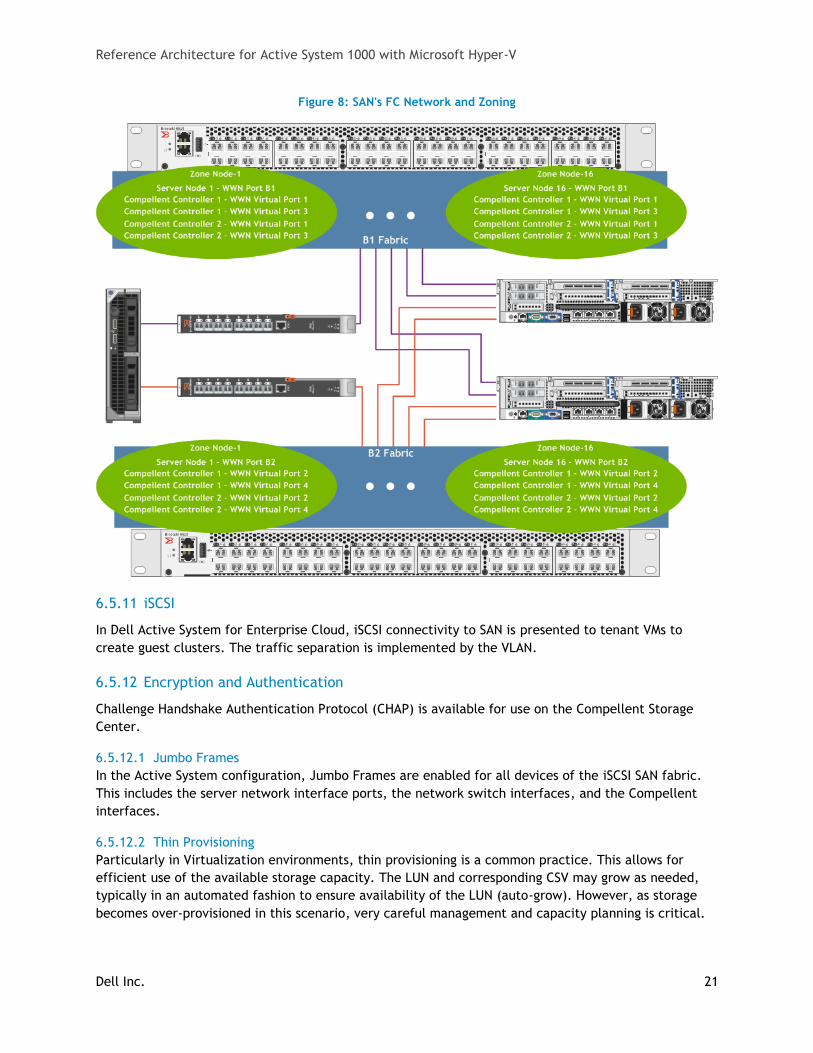
6.5.10 Fibre Channel Zoning
In the Dell Active System for Enterprise Cloud, FC zones are created on the Brocade 6510 FC SAN
switches, such that each zone consists of one initiator (one HBA port per server) and the Compellent FC
ports.
Reference Architecture for Active System 1000 with Microsoft Hyper-V
Dell Inc. 21
Figure 8: SAN's FC Network and Zoning
6.5.11 iSCSI
In Dell Active System for Enterprise Cloud, iSCSI connectivity to SAN is presented to tenant VMs to
create guest clusters. The traffic separation is implemented by the VLAN.
6.5.12 Encryption and Authentication
Challenge Handshake Authentication Protocol (CHAP) is available for use on the Compellent Storage
Center.
6.5.12.1 Jumbo Frames
In the Active System configuration, Jumbo Frames are enabled for all devices of the iSCSI SAN fabric.
This includes the server network interface ports, the network switch interfaces, and the Compellent
interfaces.
6.5.12.2 Thin Provisioning
Particularly in Virtualization environments, thin provisioning is a common practice. This allows for
efficient use of the available storage capacity. The LUN and corresponding CSV may grow as needed,
typically in an automated fashion to ensure availability of the LUN (auto-grow). However, as storage
becomes over-provisioned in this scenario, very careful management and capacity planning is critical.
Reference Architecture for Active System 1000 with Microsoft Hyper-V
Dell Inc. 22
Dell Compellent Thin Provisioning delivers the highest enterprise storage utilization possible by
eliminating pre-allocated but unused capacity. The software, Dynamic Capacity, completely separates
allocation from utilization, enabling users to provision any size volume upfront yet only consume disk
space when data is written. Thin Write technology assesses the incoming payload and designates
capacity for each write on demand, leaving unused disk space in the storage pool for other servers and
applications.
6.5.12.3 Volume Cloning
Compellent offers the Remote Instant ReplayTM feature to support volume cloning. Remote Instant
Replay leverages space-efficient snapshots between local and remote sites for cost-effective disaster
recovery and business continuity. Following initial site synchronization, only incremental changes in
enterprise data need to be replicated, minimizing capacity requirements and speeding recovery.
Known as Thin Replication, this unique approach enables network storage administrators to choose
between Fibre Channel and native IP connectivity for data transfer.
Volume Cloning is another common practice in Virtualization environments. This can be used for both
Host and VM volumes, dramatically increasing Host installation times and VM provisioning times.
6.5.12.4 Volume Snapshots
SAN Volume snapshots are a common method of providing a point-in-time, instantaneous backup of a
SAN Volume or LUN. These snapshots are typically block-level and only utilize storage capacity as
blocks change on the originating volume. Some SANs provide tight integration with Hyper-V, integrating
both the Hyper-V Microsoft Volume Shadow Copy Service (VSS) Writer on Hosts and Volume Snapshots
on the SAN. This integration provides a comprehensive and high-performing backup and recovery
solution.
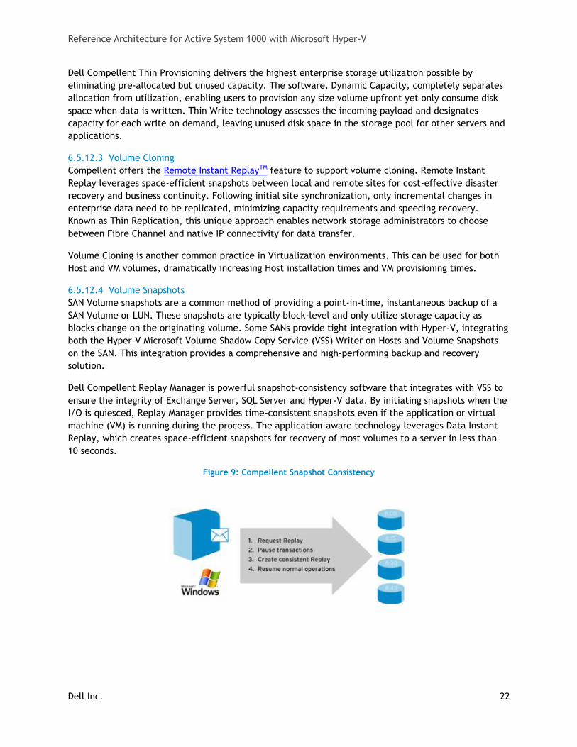
Dell Compellent Replay Manager is powerful snapshot-consistency software that integrates with VSS to
ensure the integrity of Exchange Server, SQL Server and Hyper-V data. By initiating snapshots when the
I/O is quiesced, Replay Manager provides time-consistent snapshots even if the application or virtual
machine (VM) is running during the process. The application-aware technology leverages Data Instant
Replay, which creates space-efficient snapshots for recovery of most volumes to a server in less than
10 seconds.
Figure 9: Compellent Snapshot Consistency
Reference Architecture for Active System 1000 with Microsoft Hyper-V
Dell Inc. 23
6.5.12.5 Storage Tiering
Tiering storage is the practice of physically partitioning data into multiple distinct classes based on
price, performance or other attributes. Data may be dynamically moved among classes in a tiered
storage implementation based on access activity or other considerations.
This is normally achieved through a combination of varying types of disks which are used for different
data types. (i.e. Production, non-production, backups, etc.) Dell Compellent Fluid Data storage
dynamically moves enterprise data to the optimal storage tier based on actual use. The most active
blocks reside on high-performance SSD and SAS drives, while infrequently accessed data migrates to
lower-cost, high-capacity SAS drives. The result is network storage that remains in tune with
application needs, with overall storage costs cut by up to 80%.
7 Management Infrastructure This section discusses the components and connectivity of the management infrastructure.
7.1.1 Management Components
The various management components that were introduced in the Overview section are described here
in more detail.
System Center 2012 SP1 Virtual Machine Manager Component (VMM 2012): VMM 2012 is Microsoft’s
Virtualization management platform. VMM 2012 provides in-depth management of both hypervisor and
VMs. It provides a system administrator the capability to create and deploy VM templates, manage
library stores of VMs, hardware profiles, and image files, and even manage VMware environments.
VMM 2012 also provides P2V (physical to virtual) functionality, thereby allowing a system administrator
to convert physical servers to virtual machines. VMM 2012 integrates with the hypervisor, VMs, and
System Center Operations Manager to provide a deep view of the system utilization.
Compellent Enterprise Manager: Compellent Enterprise Manager simplifies storage management by
providing a single, centralized console for the administration of multiple local and remote Compellent
systems. Users can configure and verify remote replication processes, monitor storage capacity and
disk utilization in real time, and generate comprehensive enterprise storage usage and performance
reports.
Dell Lifecycle Controller: This helps reduce operating costs by simplifying deployment and
management. Key features include diagnostics, self-update (UEFI, Driver Pack update), firmware
updates (BIOS, NIC FW, RAID Controllers), and hardware configuration.
Out-of-band CMC and iDRAC: The CMC provides a single, secure interface to manage the inventory,
configuration, monitoring, and alerting for chassis components (iKVM, CMC), I/O modules, servers, and
iDRAC. It also provides excellent real-time power management, monitoring, and alerting capabilities.
The Dell chassis provides users with system-level power limiting, slot-based prioritization, and dynamic
power engagement functionalities. The iDRAC on each server provides the flexibility to remotely
manage the server through Console redirection and Virtual CD-ROM/DVD/Floppy/Flash capabilities.
Dell | System Center 2012 SP1 Integration: Dell provides management packs for the optional System
Center components to monitor servers, storage, and networking components. These packs allow System
Center 2012 Operations Manager (SCOM) to monitor, report on, and take actions based upon alerts
generated by the individual components. Dell also provides integration tools for System Center
Configuration Manager for the Lifecycle Controller, providing a framework for bare-metal deployment
Reference Architecture for Active System 1000 with Microsoft Hyper-V
Dell Inc. 24
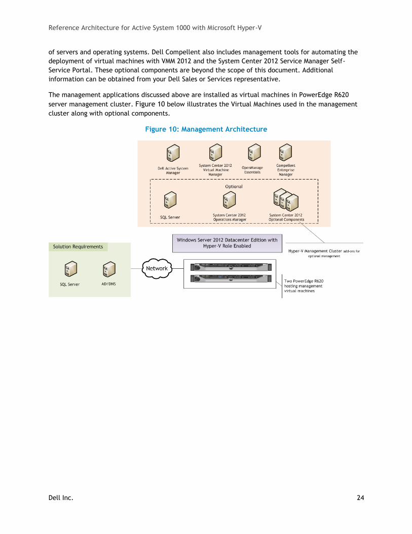
of servers and operating systems. Dell Compellent also includes management tools for automating the
deployment of virtual machines with VMM 2012 and the System Center 2012 Service Manager Self-
Service Portal. These optional components are beyond the scope of this document. Additional
information can be obtained from your Dell Sales or Services representative.
The management applications discussed above are installed as virtual machines in PowerEdge R620
server management cluster. Figure 10 below illustrates the Virtual Machines used in the management
cluster along with optional components.
Figure 10: Management Architecture
Reference Architecture for Active System 1000 with Microsoft Hyper-V
Dell Inc. 25
7.1.2 Management Connectivity
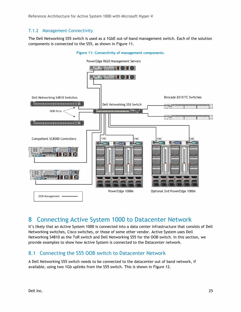
The Dell Networking S55 switch is used as a 1GbE out-of-band management switch. Each of the solution
components is connected to the S55, as shown in Figure 11.
Figure 11: Connectivity of management components.
8 Connecting Active System 1000 to Datacenter Network It’s likely that an Active System 1000 is connected into a data center infrastructure that consists of Dell
Networking switches, Cisco switches, or those of some other vendor. Active System uses Dell
Networking S4810 as the ToR switch and Dell Networking S55 for the OOB switch. In this section, we
provide examples to show how Active System is connected to the Datacenter network.
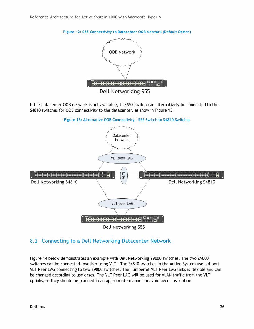
8.1 Connecting the S55 OOB switch to Datacenter Network
A Dell Networking S55 switch needs to be connected to the datacenter out of band network, if
available, using two 1Gb uplinks from the S55 switch. This is shown in Figure 12.
Reference Architecture for Active System 1000 with Microsoft Hyper-V
Dell Inc. 26
Figure 12: S55 Connectivity to Datacenter OOB Network (Default Option)
If the datacenter OOB network is not available, the S55 switch can alternatively be connected to the
S4810 switches for OOB connectivity to the datacenter, as show in Figure 13.
Figure 13: Alternative OOB Connectivity - S55 Switch to S4810 Switches
8.2 Connecting to a Dell Networking Datacenter Network
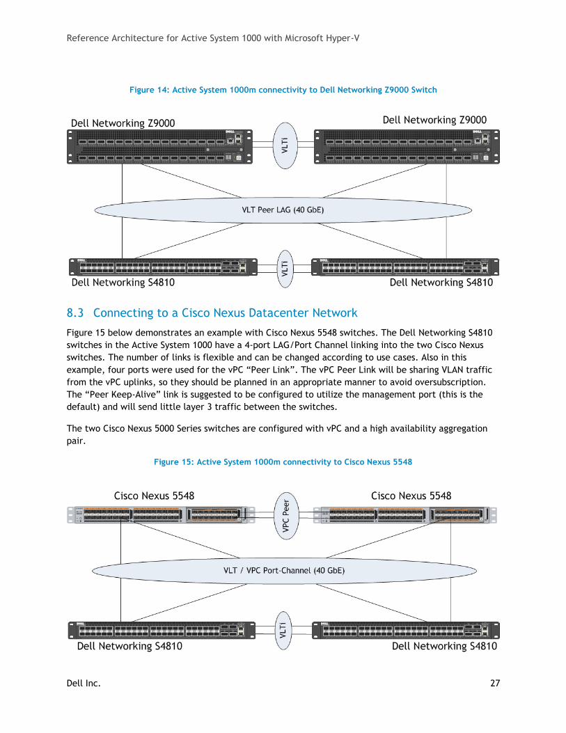
Figure 14 below demonstrates an example with Dell Networking Z9000 switches. The two Z9000
switches can be connected together using VLTi. The S4810 switches in the Active System use a 4-port
VLT Peer LAG connecting to two Z9000 switches. The number of VLT Peer LAG links is flexible and can
be changed according to use cases. The VLT Peer LAG will be used for VLAN traffic from the VLT
uplinks, so they should be planned in an appropriate manner to avoid oversubscription.
Reference Architecture for Active System 1000 with Microsoft Hyper-V
Dell Inc. 27
Figure 14: Active System 1000m connectivity to Dell Networking Z9000 Switch
8.3 Connecting to a Cisco Nexus Datacenter Network
Figure 15 below demonstrates an example with Cisco Nexus 5548 switches. The Dell Networking S4810
switches in the Active System 1000 have a 4-port LAG/Port Channel linking into the two Cisco Nexus
switches. The number of links is flexible and can be changed according to use cases. Also in this
example, four ports were used for the vPC “Peer Link”. The vPC Peer Link will be sharing VLAN traffic
from the vPC uplinks, so they should be planned in an appropriate manner to avoid oversubscription.
The “Peer Keep-Alive” link is suggested to be configured to utilize the management port (this is the
default) and will send little layer 3 traffic between the switches.
The two Cisco Nexus 5000 Series switches are configured with vPC and a high availability aggregation
pair.
Figure 15: Active System 1000m connectivity to Cisco Nexus 5548

Reference Architecture for Active System 1000 with Microsoft Hyper-V
Dell Inc. 28
9 Scalability As workloads increase, the solution can be scaled to provide additional compute and storage resources
independently.
Scaling Compute and Network Resources: This solution is configured with two S4810 network
switches. Up to two PowerEdge M1000e chassis can be added to the two Dell Networking switches. In
order to scale the compute nodes beyond two chassis, new S4810 switches need to be added.
Scaling Storage Resources: Compellent storage can be scaled seamlessly and independent of the
compute and network architectures. Additional drives and enclosures can be added to the existing
controllers. New volumes can be created or existing volumes can be expanded to utilize the capacity in
the added enclosures. This design is currently limited to four additional enclosures in the single rack
configuration and eight additional enclosures in the two rack configurations. The Compellent SC8000
controllers can scale up to a maximum of 960 drives. To scale beyond these limits, additional racks and
controllers can be added to the solution and connected to the Brocade 6510 switches.
10 Delivery Model This Reference architecture can be purchased as a complete solution, the Active System 1000m. This
solution is available to be racked, cabled, and delivered to the customer site, to speed deployment.
Dell Services will deploy and configure the solution tailored to the business needs of the customer and
based on the architecture developed and validated by Dell Engineering. For more details or questions
about the delivery model, please consult with your Dell Sales representative.
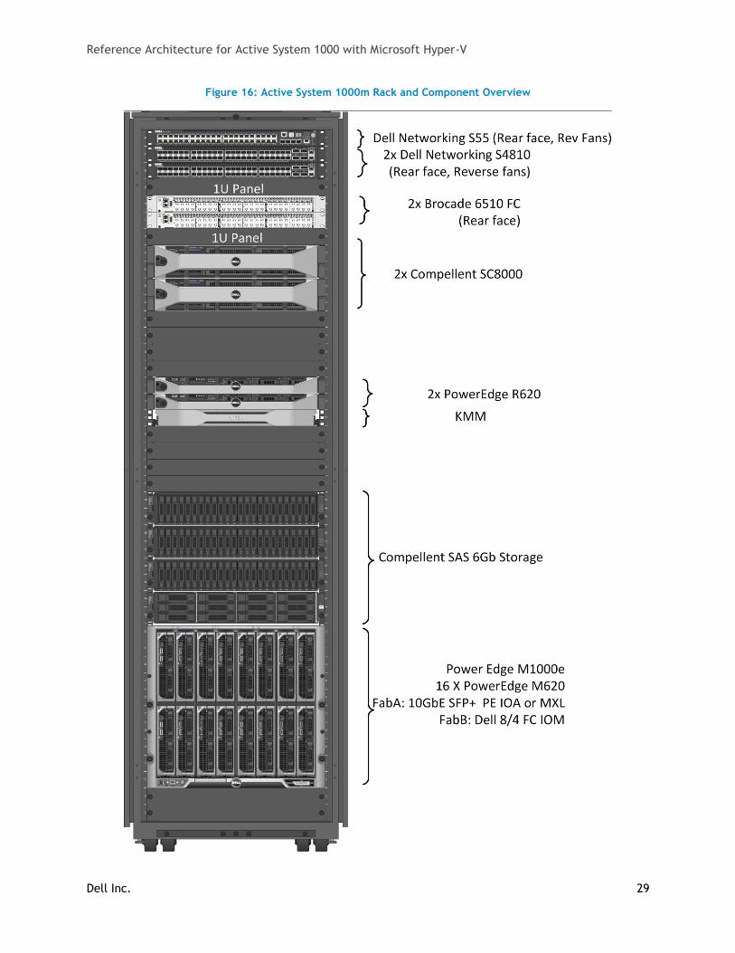
Figure 16 below shows the Active System 1000m solution with a single chassis and up to 16 compute
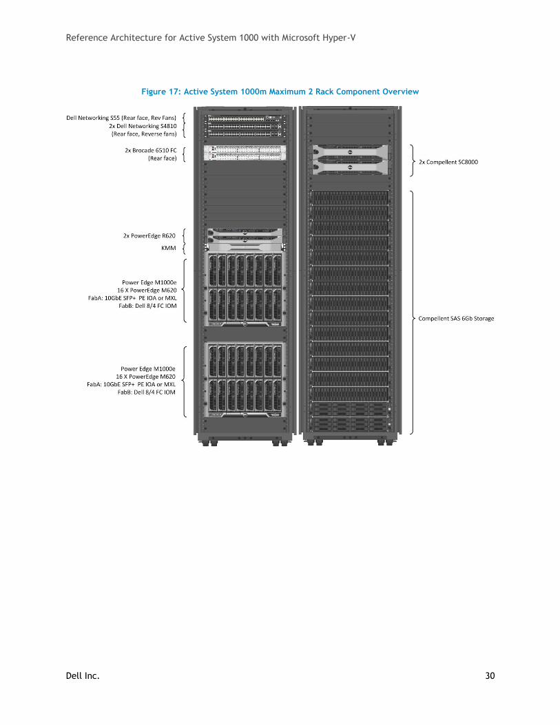
hosts in a one rack configuration that also contains supporting Compellent storage. Figure 17 shows
Active System 1000m with two chassis with up to 32 compute hosts and maximum of 16 storage
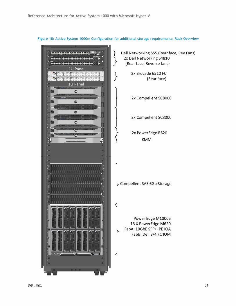
enclosures in a two rack configuration. Figure 18 shows the configuration with one chassis and 16
compute hosts and four storage controllers available with the Active System 1000m solution. Note that
switches shown in figures are shown mounted forward for representation. In actual use, ports face the
back of the rack. PDUs shown are for illustration and will vary by region or customer power
requirements. Additional PDUs are utilized within the rack.
Reference Architecture for Active System 1000 with Microsoft Hyper-V
Dell Inc. 29
Figure 16: Active System 1000m Rack and Component Overview
Reference Architecture for Active System 1000 with Microsoft Hyper-V
Dell Inc. 30
Figure 17: Active System 1000m Maximum 2 Rack Component Overview
Reference Architecture for Active System 1000 with Microsoft Hyper-V
Dell Inc. 31
Figure 18: Active System 1000m Configuration for additional storage requirements: Rack Overview
Reference Architecture for Active System 1000 with Microsoft Hyper-V
Dell Inc. 32
11 Additional Supported Configurations Dell Active System 1000 supports two additional network configurations. Dell Active System 1000
supports two additional network configurations. The customer can choose to have a Dell Networking
S5000 (1U 10/40GbE LAN/SAN switch equipped with native FC and FCoE capabilities) switch as a LAN
Top of Rack switch or a Cisco Nexus 5548 (1RU 10 Gigabit Ethernet, Fibre Channel, and FCoE) switch as
LAN Top of Rack switch. These switches are not pre-racked with Active System 1000 solution.
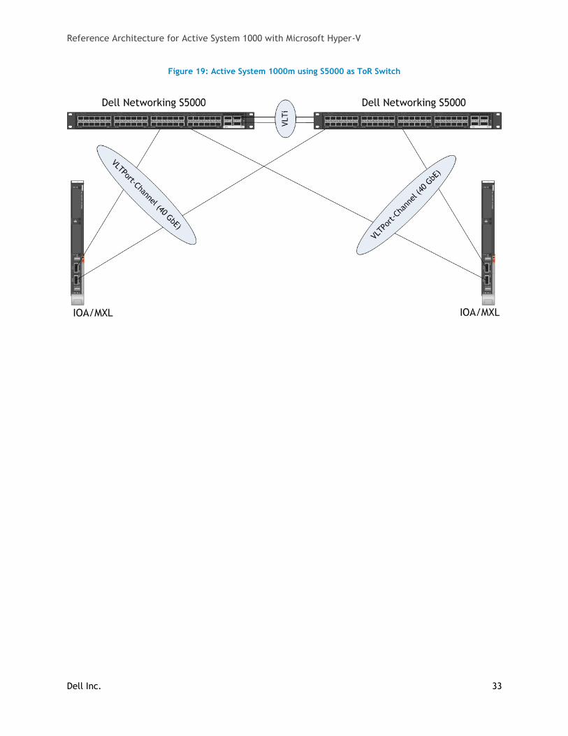
11.1 Dell Networking S5000 as LAN Top of Rack Switch
The Dell Networking S5000 is a first-of-its-kind modular, 1 rack unit (RU) 10/40GbE top-of-rack (ToR)
LAN/SAN switch equipped with native FC and Fiber Channel over Ethernet (FCoE) capabilities. The
S5000 switch’s innovative system design is powered by an industry-hardened and feature-rich operating
system for maximum dependability and uptime. Dell Open Automation framework provides integrated
automation, scripting, and programmable management for enhanced network flexibility in virtualized
environments.
Key features include:
Pay-as-you grow modularity, designed to scale – provides for greater deployment flexibility
and IT budget allocation compared to fixed-port switches. The S5000 switch accommodates
four modules allowing customers to populate a single module and add modules as necessary
instead of buying all four modules at once.
High-density LAN/SAN convergence – saves on the number of switches and rack space
required, the S5000 switch has up to 1.3 to 2.6 times the port density per rack unit compared
to industry alternatives. The S5000 switch has a maximum of 64 x 10GbE ports, or 48 x
Ethernet/FC ports with 16 x 10GbE ports.
Feature-rich storage networking – complete support for iSCSI, RDMA over Converged Ethernet
(RoCE), Network Attached Storage (NAS), FCoE, and FC fabric services, all on the same
platform.
Future-proof design for maximum investment protection – with the modularity and system
design, the S5000 switch hardware is future-proofed to support newer features and options
when released without needing to sacrifice existing infrastructure investment.
Easy integration and proven interoperability with leading adapter, switch, and storage vendors
including Broadcom, Brocade, Emulex, Intel, and Qlogic.
The connectivity between the Dell Networking S5000 switch and the blade I/O modules is similar to the
connectivity between the S4810 switch and the blade I/O modules. The blade I/O modules connect to
the S5000 ToR switch through the 40Gb ports on the I/O modules to 40Gb ports on the S5000 switch.
The two Dell Networking S5000 switches are configured with Virtual Line Trunking (VLT) using two 40
Gbps QSFP+ links. VLT Interconnects are created between the two 40 Gbps QSFP+ ports, providing a
path for communication across the switches. Figure 19 below shows the connectivity between S5000
switches and blade I/O modules.
Reference Architecture for Active System 1000 with Microsoft Hyper-V
Dell Inc. 33
Figure 19: Active System 1000m using S5000 as ToR Switch
Reference Architecture for Active System 1000 with Microsoft Hyper-V
Dell Inc. 34
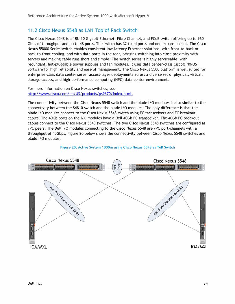
11.2 Cisco Nexus 5548 as LAN Top of Rack Switch
The Cisco Nexus 5548 is a 1RU 10 Gigabit Ethernet, Fibre Channel, and FCoE switch offering up to 960
Gbps of throughput and up to 48 ports. The switch has 32 fixed ports and one expansion slot. The Cisco
Nexus 55000 Series switch enables consistent low-latency Ethernet solutions, with front-to-back or
back-to-front cooling, and with data ports in the rear, bringing switching into close proximity with
servers and making cable runs short and simple. The switch series is highly serviceable, with
redundant, hot-pluggable power supplies and fan modules. It uses data center-class Cisco® NX-OS
Software for high reliability and ease of management. The Cisco Nexus 5500 platform is well suited for
enterprise-class data center server access-layer deployments across a diverse set of physical, virtual,
storage-access, and high-performance computing (HPC) data center environments.
For more information on Cisco Nexus switches, see
http://www.cisco.com/en/US/products/ps9670/index.html.
The connectivity between the Cisco Nexus 5548 switch and the blade I/O modules is also similar to the
connectivity between the S4810 switch and the blade I/O modules. The only difference is that the
blade I/O modules connect to the Cisco Nexus 5548 switch using FC transceivers and FC breakout
cables. The 40Gb ports on the I/O modules have a Dell 40Gb FC transceiver. The 40Gb FC breakout
cables connect to the Cisco Nexus 5548 switches. The two Cisco Nexus 5548 switches are configured as
vPC peers. The Dell I/O modules connecting to the Cisco Nexus 5548 are vPC port-channels with a
throughput of 40Gbps. Figure 20 below shows the connectivity between Cisco Nexus 5548 switches and
blade I/O modules.
Figure 20: Active System 1000m using Cisco Nexus 5548 as ToR Switch
Reference Architecture for Active System 1000 with Microsoft Hyper-V
Dell Inc. 35
12 Reference
12.1 Dell Active System Manager
Specification for the Dell Active System Manager can be found here.
http://content.dell.com/us/en/enterprise/d/shared-content~solutions~en/Documents~active-system-
manager-spec-sheet.pdf.aspx
12.2 Dell Active Infrastructure Wiki
Wiki articles on Dell Active Infrastructure can be found here.
http://en.community.dell.com/techcenter/converged-infrastructure/w/wiki/default.aspx
12.3 Dell PowerEdge Server Documentation and Hardware/Software Updates
For Drivers and other downloads: Visit
http://www.dell.com/support/home/us/en/04?c=us&l=en&s=bsd, enter a server service tag or select
“Servers, Storage & Networking” product category, then select the server model and operating system
version.
12.4 Dell Virtualization Documentation
Dell TechCenter Microsoft Windows Server 2012 Blogs/Wiki Site:
http://en.community.dell.com/techcenter/os-applications/w/wiki/3458.microsoft-windows-server-
2012.aspx
Microsoft® Windows Server® 2012 With Hyper-V™ for Dell™ PowerEdge™ Systems Important
Information Guide:
http://support.dell.com/support/edocs/SOFTWARE/WS2012/
12.5 Microsoft® Hyper-V Documentation
Hyper-V Getting Started Guide:
http://technet.microsoft.com/library/hh846766.aspx
Hyper-V: Using Hyper-V and Failover Clustering:
http://technet.microsoft.com/library/hh831531
Building Your Cloud Infrastructure: Converged Data Center without Dedicated Storage Nodes
http://technet.microsoft.com/en-us/library/hh831829.aspx
12.6 Microsoft® Management Software
Microsoft System Center 2012:
http://www.microsoft.com/en-us/server-cloud/system-center/datacenter-management.aspx
Reference Architecture for Active System 1000 with Microsoft Hyper-V
Dell Inc. 36
System Center 2012 Virtual Machine Manager Deployment:
http://technet.microsoft.com/en-us/library/gg610669
12.7 Microsoft® Roles and Features
Failover Clustering in Windows Server 2012:
http://technet.microsoft.com/library/hh831579