Embed Size (px)
DESCRIPTION
f
Citation preview

Cisco ConfidentialCopyright © 1998 Cisco Systems, Inc. All Rights Reserved.
Page 1 of 80
DESIGN IMPLEMENTATION GUIDE
Voice over IPby Jon Davidson ([email protected])
Network to User Business Unit—PME
Abstract
Telephony is the most pervasive of all technologies. There is no other technology that people are more comfortable and familiar
with than a standard telephone handset. Many corporations are seeking nontraditional methods to reduce their voice costs while
giving the user the same comfort level and familiarity. Cost reduction has fueled the convergence of data and voice networks. As
more data and voice networks converge, careful design and planning must occur to assure that the quality and reliability of the
voice network are not affected.
This guide describes several technologies that have enabled packet telephony and specifically, voice over IP. Design issues
are covered, as well as brief tutorials on voice, fax, H.323, and voice over IP. This guide is not meant as an in depth tutorial in voice
technology; it gives you a basic understanding of voice technology as it applies in a packet environment.
Commonly Used Terms in this Guide
A-Law—ITU-T logarithmic pulse code modulation (PCM) standard (G.711) used in the conversion between analog and
digital signals; used mainly in Europe
Busy hour—Time period that has the greatest call volume; assists telephone companies with designing their network to a certain
capacity
Class of service (CoS)—Method of classifying different traffic flows into a category and applying a particular quality of service
(QoS) for that flow
Coder-decoder (CODEC)—Transforms analog voice into a digital bit stream and vice versa; also used to indicate the compression
type (for example, G.729 CODEC)
Compressed Real-Time Transfer Protocol (CRTP)—Specification for compressing Real-Time Transport Protocol (RTP) headers
Delay—Time necessary to get from point A to point B
Dual tone multifrequency (DTMF) tone detection—A method for touch-tone phones developed to make dialing an easier process;
each digit corresponds to one of 16 combinations of pairs of sine waves chosen from eight different frequencies (example: the 7
digit is defined as the combination of 852 Hz and 1209 Hz)

Cisco ConfidentialCopyright © 1998 Cisco Systems, Inc. All Rights Reserved.
Page 2 of 80
Ear and Mouth or REceive and TransMit (E&M)—Signaling technique used normally on trunk lines between private branch
exchange (PBX) equipment
Echo cancellation—Process in which the echo is removed from the line; echoes are usually caused by a mismatch in impedance in
the wiring of a telephone network; an echo canceller keeps a sample of the speech just sent and if it hears the inverse of that speech
coming back in the opposite direction, it subtracts the original speech from the inversed signal
Foreign exchange office (FXO)—Interface that mimics a standard telephone handset (that is, requires another device to provide
it dial tone)
Foreign exchange station (FXS)—Interface that mimics the Public Switched Telephone Network (PSTN); provides dial tone to
a standard telephone handset
Gatekeeper—Optional in an H.323 system, provides call control services to the H.323 endpoints; more than one gatekeeper may
be present, and they communicate with each other in an unspecified fashion; the gatekeeper is logically separate from the endpoints,
but its physical implementation may coexist with a terminal, multipoint conference unit (MCU), gateway, multipoint controller
(MP), or other non-H.323 LAN device
Gateway—An optional element in an H.323 conference; an H.323 gateway is an endpoint on the LAN that provides for real-time,
two-way communications between H.323 terminals on the LAN and other ITU terminals on a WAN, or to another H.323 gateway
H.323—ITU-T specification for real-time multimedia applications
Jitter—Variation of a interpacket arrival time
Latency—The time between when a device requests access to a network and when it is granted permission to transmit; one
component of latency; end-to-end latency is often used to describe the delay associated in a network
Maximum transmission unit (MTU)—Maximum packet size, in bytes, that a particular interface transmits
MU-Law—Northern American logarithmic PCM standard (also specified in ITU-T G,711) used in the conversion between analog
and digital signals
Multipoint control unit (MCU)—An endpoint on the LAN that provides the capability for three or more terminals and gateways
to = participate in a multipoint conference; may also connect two terminals in a point-to-point conference that may later develop
into a multipoint conference; the MCU generally operates in the fashion of an H.231 MCU, but an audio processor is not
mandatory; the MCU consists of two parts: a mandatory multipoint controller and optional multipoint processors (MPs). In the
simplest case, an MCU may consist of only an MC, with no MPs.
Multipoint controller—An H.323 entity on the LAN that provides for the control of three or more terminals participating in a
multipoint conference; may also connect two terminals in a point-to-point conference that may later develop into a multipoint
conference; provides for capability negotiation with all terminals to achieve common levels of communications; it also may control
conference resources such as who is multicasting video; does not perform mixing or switching of audio, video, and data
Multipoint processor—An H.323 entity on the LAN that provides for the centralized processing of audio, video, or data streams
in a multipoint conference; provides for the mixing, switching, or other processing of media streams under the control of the
MC; may process a single media stream or multiple media streams, depending on the type of conference supported
Quality of Service (QoS)—General term that describes a level of service necessary for a specific application
RAS (Registration/Admission/Status)—H.323 protocol that allows communication between a H.323 gatekeeper and a gateway
Real-Time Transport Protocol (RTP)—RFC 1889—Part of the ITU-T H.323 specification for streaming real-time applications
Resource Reservation Protocol (RSVP)—Protocol that defines the ability to dynamically reserve or allocate bandwidth and latency
to a particular traffic flow

Cisco ConfidentialCopyright © 1998 Cisco Systems, Inc. All Rights Reserved.
Page 3 of 80
T.4—ITU-T protocol that describes the formatting of page image data in fax transmission
T.30—ITU-T Fax Session Control Protocol that describes the formatting of nonpage data such as capabilities negotiation messages
in fax transmission
T.120—Portion of the ITU-T H.323 specification that relates to data-sharing applications (whiteboarding, and so on)
Type of Service (ToS)—Portion of the IP header that relates to the service level of the packet
Voice Activity Detection (VAD)—Allows for differentiation between speech and silence; packet-based networks take advantage
of VAD by not transmitting silence
Voice Primer
Voice technology has been with us for over one hundred years. The voice network has been evolving ever since the first phone call
was made. Many of the current acronyms and architectures of voice are decisions that were made several decades ago. The standard
PSTN is basically a large circuit-switched network. The telephony network is truly a ubiquitous one; it is simple to use, dependable,
and pervasive in our lives.
As with any large network, the numbering scheme is one of the most important issues. In North America, the North American
Numbering Plan (NANP) is used. This plan consists of an area code, office code, and station code. Area codes are assigned
geographically, office codes are assigned to specific switches, and station codes identify a specific port on that switch. The format
used is 1Nxx-NXX-XXXX, with N = 2 - 9 and X = 0 - 9. These numbering plans normally conform to the ITU-T E.164
recommendations, which cover the international dialing plan as well as many other recommendations.
For an international calling plan, each country is assigned a one- to three-digit country code; the country’s dialing plan follows
the country code.
To fully understand voice technology, both analog and digital transmission and signaling must be understood. Human
speech and everything we hear is in analog form. Up until several decades ago, the telephony network was based upon an analog
infrastructure as well.
The components of an early-generation analog phone call were a carbon microphone, a battery, an electromagnet, and an iron
diaphragm. Connecting these components produced a method of transporting voice.
While analog communication is ideal for human communication, analog transmission is neither robust nor efficient
at recovering from line noise. In the early telephony network, when analog transmission was passed through amplifiers to boost
the signal, not only did the voice get boosted, but the line noise was also amplified. This line noise resulted in an often-unusable
connection.
Digital samples are comprised of one and zero bits. It is much easier for digital samples to be separated from line noise.
Therefore, when signals are regenerated, a clean sound can be maintained. When the benefits of this digital representation
became evident, the telephony network migrated to pulse code modulation (PCM).
PCM converts analog sound into digital form by sampling the analog sound 8000 times per second and converting each sample
into a numeric code. The Nyquist theorem states that if you sample an analog signal at twice the rate of the highest frequency of
interest, you can accurately reconstruct that signal back into its analog form. Since most speech content is below 4000 Hz (4 kHz),
the sampling rate needed is 8000 times per second (125 microseconds between samples).
After the waveform is sampled, it is converted into a discrete digital form. This sample is represented by a code that indicates
the amplitude of the waveform at the instant the sample was taken. The telephony form of PCM uses 8 bits for the code and a
logarithm compression method that assigns more bits to lower-amplitude signals. The transmission rate is obtained by multiplying
8000 samples per second times 8 bits per sample, giving 64,000 bits per second, the standard transmission rate for one channel of
telephone digital communications.

Cisco ConfidentialCopyright © 1998 Cisco Systems, Inc. All Rights Reserved.
Page 4 of 80
Two basic variations of 64-kbps PCM are commonly used: MU-law and A-law. The methods are similar in that they both use
logarithmic compression to achieve 12 to 13 bits of linear PCM quality in 8 bits, but are different in relatively minor compression
details (MU-law has a slight advantage in low-level signal-to-noise ratio performance). Usage has historically been along country
and regional boundaries, with North America using MU-law and Europe using A-law modulation. It is important to note that when
making a long-distance call, any required MU-law to A-law conversion is the responsibility of the MU-law country.
Another compression method often used is adaptive differential pulse code modulation (ADPCM). A commonly used instance
of ADPCM, ITU-T G.726 encodes using 4-bit samples, giving a transmission rate of 32 kbps. Unlike PCM, the 4 bits do not directly
encode the amplitude of speech, but the differences in amplitude as well as the rate of change of that amplitude, employing some
very rudimentary linear prediction.
PCM and ADPCM are examples of “waveform” CODECS—compression techniques that exploit redundant characteristics of
the waveform itself. New compression techniques have been developed over the past 10 to 15 years that further exploit knowledge
of the source characteristics of speech generation. These techniques employ signal processing techniques that compress speech by
sending only simplified parametric information about the original speech excitation and vocal tract shaping, requiring less
bandwidth to transmit that information. These techniques can be grouped together generally as “source” CODECS, and include
variations such as linear predictive coding (LPC), Code Excited Linear Prediction (CELP), and multipulse, multilevel quantization
(MP-MLQ).
CELP, MP-MLQPCM, and ADPCM coding schemes are standardized by the ITU-T in its G-series recommendations. The most
popular voice coding standards for telephony and packet voice include:
• G.711, which describes the 64-kbps PCM voice coding technique outlined earlier; G.711 encoded voice is already in the correct
format for digital voice delivery in the public phone network or through PBXs
• G.726, which describes ADPCM coding at 40, 32, 24, and 16 kbps; ADPCM voice may also be interchanged between packet
voice and public phone or PBX networks, provided that the latter has ADPCM capability
• G.728, which describes a 16-kbps low-delay variation of CELP voice compression; CELP voice coding must be transcoded to a
public telephony format for delivery to or through telephone networks
• G.729, which describes CELP compression that enables voice to be coded into 8-kbps streams; two variations of this standard
(G.729 and G.729 Annex A) differ largely in computational complexity, and both generally provide speech quality as good as that
of 32-kbps ADPCM
• G.723.1, which describes a compression technique that can be used for compressing speech or other audio signal components of
multimedia service at a very low bit rate, as part of the overall H.324 family of standards; this coder has two bit rates associated
with it—5.3 and 6.3 kbps; the higher bit rate is based on MP-MLQ technology and has greater quality; the lower bit rate is based
on CELP, gives good quality, and provides system designers with additional flexibility
As CODECS rely more and more on subjectively tuned compression techniques, standard objective quality measures such as total
harmonic distortion and signal-to-noise ratios have less correlation with perceived CODEC quality. A common benchmark for
quantifying the performance of the speech CODEC is the mean opinion score (MOS). Since voice quality and sound in general is
subjective to the listener, it is important to get a wide range of listeners and sample material. MOS tests are given to a group of
listeners who give each sample of speech material a rating of 1 (bad) to 5 (excellent). The scores are then averaged to get the mean
opinion score. MOS testing is also used to compare how well a particular CODEC works under varying circumstances, including
differing background noise levels, multiple encodes and decodes, and so on. This data can then be used to compare against other
CODECS.
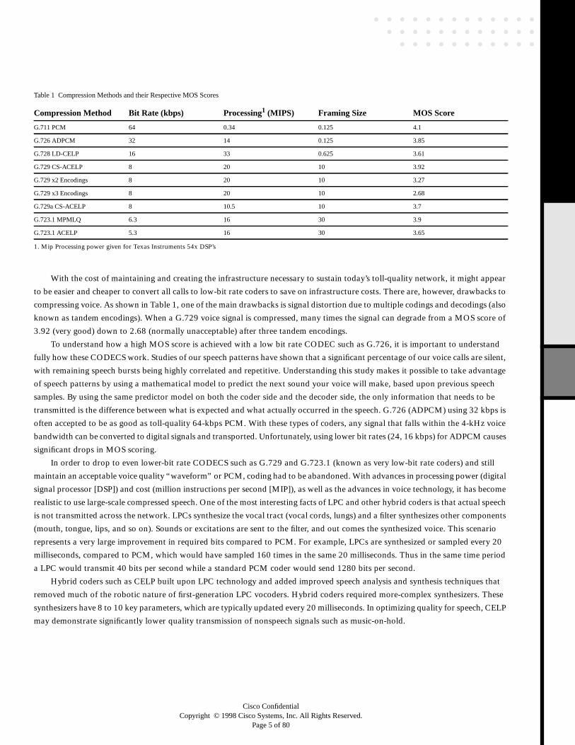
MOS scoring for several ITU-T CODECS is illustrated in (Table 1). This table shows the relationship between several low-bit
rate coders and standard PCM.
Cisco ConfidentialCopyright © 1998 Cisco Systems, Inc. All Rights Reserved.
Page 5 of 80
With the cost of maintaining and creating the infrastructure necessary to sustain today’s toll-quality network, it might appear
to be easier and cheaper to convert all calls to low-bit rate coders to save on infrastructure costs. There are, however, drawbacks to
compressing voice. As shown in Table 1, one of the main drawbacks is signal distortion due to multiple codings and decodings (also
known as tandem encodings). When a G.729 voice signal is compressed, many times the signal can degrade from a MOS score of
3.92 (very good) down to 2.68 (normally unacceptable) after three tandem encodings.
To understand how a high MOS score is achieved with a low bit rate CODEC such as G.726, it is important to understand
fully how these CODECS work. Studies of our speech patterns have shown that a significant percentage of our voice calls are silent,
with remaining speech bursts being highly correlated and repetitive. Understanding this study makes it possible to take advantage
of speech patterns by using a mathematical model to predict the next sound your voice will make, based upon previous speech
samples. By using the same predictor model on both the coder side and the decoder side, the only information that needs to be
transmitted is the difference between what is expected and what actually occurred in the speech. G.726 (ADPCM) using 32 kbps is
often accepted to be as good as toll-quality 64-kbps PCM. With these types of coders, any signal that falls within the 4-kHz voice
bandwidth can be converted to digital signals and transported. Unfortunately, using lower bit rates (24, 16 kbps) for ADPCM causes
significant drops in MOS scoring.
In order to drop to even lower-bit rate CODECS such as G.729 and G.723.1 (known as very low-bit rate coders) and still
maintain an acceptable voice quality “waveform” or PCM, coding had to be abandoned. With advances in processing power (digital
signal processor [DSP]) and cost (million instructions per second [MIP]), as well as the advances in voice technology, it has become
realistic to use large-scale compressed speech. One of the most interesting facts of LPC and other hybrid coders is that actual speech
is not transmitted across the network. LPCs synthesize the vocal tract (vocal cords, lungs) and a filter synthesizes other components
(mouth, tongue, lips, and so on). Sounds or excitations are sent to the filter, and out comes the synthesized voice. This scenario
represents a very large improvement in required bits compared to PCM. For example, LPCs are synthesized or sampled every 20
milliseconds, compared to PCM, which would have sampled 160 times in the same 20 milliseconds. Thus in the same time period
a LPC would transmit 40 bits per second while a standard PCM coder would send 1280 bits per second.
Hybrid coders such as CELP built upon LPC technology and added improved speech analysis and synthesis techniques that
removed much of the robotic nature of first-generation LPC vocoders. Hybrid coders required more-complex synthesizers. These
synthesizers have 8 to 10 key parameters, which are typically updated every 20 milliseconds. In optimizing quality for speech, CELP
may demonstrate significantly lower quality transmission of nonspeech signals such as music-on-hold.
1. Mip Processing power given for Texas Instruments 54x DSP’s
Table 1 Compression Methods and their Respective MOS Scores
Compression Method Bit Rate (kbps) Processing1 (MIPS) Framing Size MOS Score
G.711 PCM 64 0.34 0.125 4.1
G.726 ADPCM 32 14 0.125 3.85
G.728 LD-CELP 16 33 0.625 3.61
G.729 CS-ACELP 8 20 10 3.92
G.729 x2 Encodings 8 20 10 3.27
G.729 x3 Encodings 8 20 10 2.68
G.729a CS-ACELP 8 10.5 10 3.7
G.723.1 MPMLQ 6.3 16 30 3.9
G.723.1 ACELP 5.3 16 30 3.65
Cisco ConfidentialCopyright © 1998 Cisco Systems, Inc. All Rights Reserved.
Page 6 of 80
With these new coders comes a few trade-offs in design. Tandem encodings have already been discussed, but it is also important
to discuss other issues that revolve around very low-bit rate coders such as coder delay, bandwidth/quality trade-offs, echo, and
total end-to-end delay.
While compressing voice packets down to 8 kbps seems ideal, with that gained bandwidth come quality trade-offs. Customers
should exercise some additional care in designing voice networks with low-bit rate compression. One of the most important of the
design criteria is minimizing total one-way end-to-end delay. This total delay has been found to be acceptable as long as it remains
within 150 to 200 milliseconds. This total delay includes CODEC-introduced delay as well as network, speed of light, and other
factors. While your specific customer may require less or more delay, it is important to understand what network delay is (somewhat
manageable) and what CODEC-introduced delay is (relatively constant).
Delay
Two types of delay are inherent in today’s telephony networks: propagation delay and handling delay. Propagation delay is caused
by the speed of light in fiber- or copper-based networks. Handling delay, also known as serialization delay, is caused by devices that
handle the voice information by devices along the voice path.
The speed of light in a vacuum is 186,000 miles per second, and electrons travel 100,000 miles per second in copper. A fiber
network halfway around the world (13,000 miles) would induce a one-way delay of about 70 milliseconds. Although this delay
is almost imperceptible to the human ear, propagation delays in conjunction with handling delays can cause noticeable
speech degradation.
Handling delays can impact traditional phone networks, but they are a larger issue in packetized environments. The following
paragraphs discuss the different handling delays and how they affect voice quality.
G.729 has an algorithmic delay of about 20 milliseconds. In the Cisco IOS™ voice over IP product, the DSP generates a frame
every 10 milliseconds. Two of these speech frames are then placed within one packet; the packet delay is, therefore, 20 milliseconds.
Vendors can decide how many frames they want to send in one packet. Cisco has given the DSP as much of the responsibility for
packetization as possible to keep the router overhead low. For example, the RTP header is put on the frame in the DSP instead of
giving the router that task.
There are other causes of delay in a packet-based network: the time necessary to move the actual packet to the output queue,
and queue delay. Cisco IOS software is quite good at moving and determining the destination of a packet. (This fact is mentioned
because other packet-based solutions [PC based, and others] are not as good at determining packet destination and moving the
actual packet to the output queue.) The actual queue delay of the output queue is another cause of delay. This factor should be kept
to under 10 milliseconds whenever possible by using whatever queuing methods are optimal for that network. This subject is
covered in greater detail in the “Quality of Service” section.
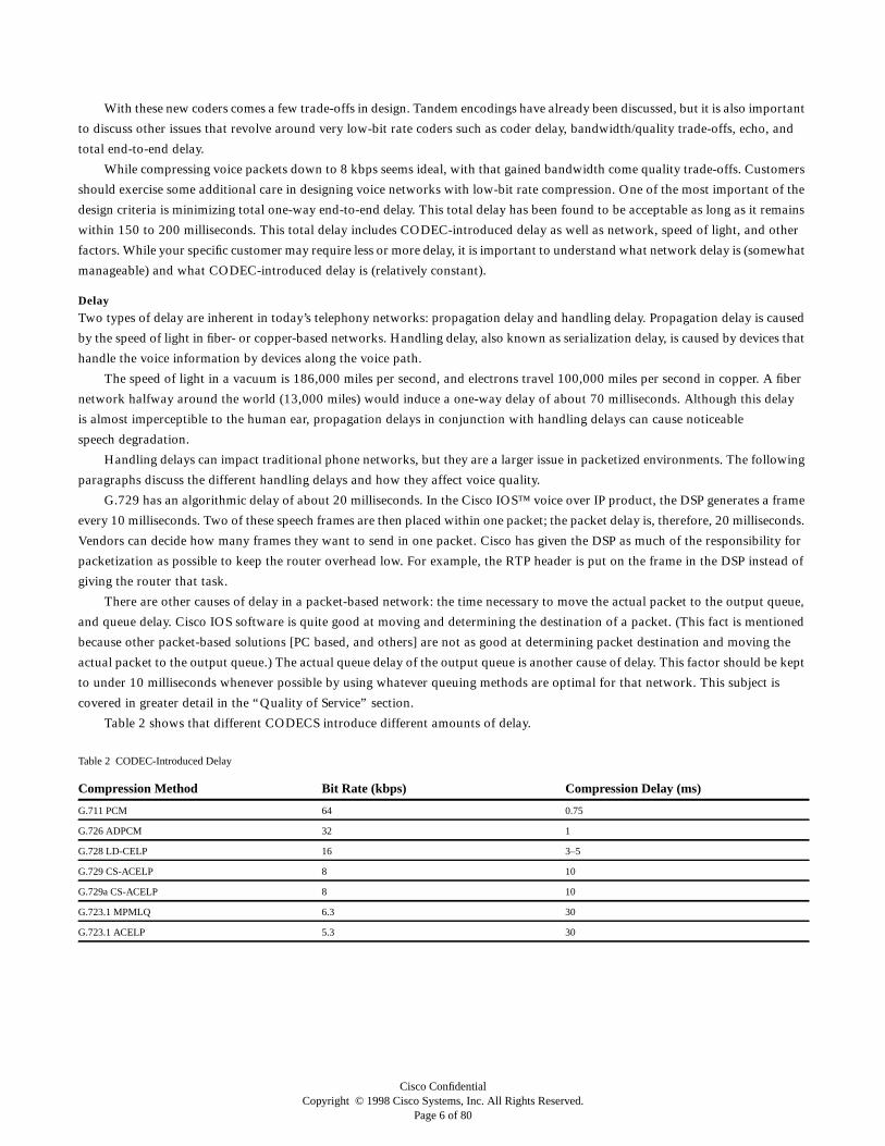
Table 2 shows that different CODECS introduce different amounts of delay.
Table 2 CODEC-Introduced Delay
Compression Method Bit Rate (kbps) Compression Delay (ms)
G.711 PCM 64 0.75
G.726 ADPCM 32 1
G.728 LD-CELP 16 3–5
G.729 CS-ACELP 8 10
G.729a CS-ACELP 8 10
G.723.1 MPMLQ 6.3 30
G.723.1 ACELP 5.3 30
Cisco ConfidentialCopyright © 1998 Cisco Systems, Inc. All Rights Reserved.
Page 7 of 80
Two additional issues affect delay. The absolute delay can interfere with the standard rhythm of a phone call, and delay
variation or jitter can also impact speech quality. Absolute delay can cause breaks in the rhythm or cadence of a phone call and
if the delay is great enough, can make the call CB-like, with talkers having to take turns talking and ending with a keyword instead
of silence to denote the end of a talker’s turn.
Jitter is the variation from when a packet was expected to be received and when it actually is received. Voice devices have
to compensate for jitter by setting up a playout buffer to play back voice in a smooth fashion and avoid discontinuity in the
voice stream.
From the user’s perspective, the configuration of the playout control is quite simple. With RTP encapsulation, an adaptive
(default) or a nonadaptive playout-delay mode can be selected. In either mode, an initial value called nominal delay needs to be
specified (with a default value of 60 msec). For nonadaptive mode, this is the fixed value for jitter (variable component of the
network delay) compensation that is used for the duration of the call. For adaptive mode, the maximum delay also needs to be
specified (with a default of 200 msec, this scenario ensures that for terrestrial connections, the end-to-end delay for G.729 will
be less than 300 msec, an important mark). Thus the adaptive playout delay will be capped by this value. There are two reasons
for this. First, the maximum delay is limited by DSP memory resources allocated for the jitter buffer. In the current firmware release,
this memory resource is 200 msec for 64K CODECS and 1360 msec for 8K CODECS. Second, it allows for setting an upper limit
on this component, in many cases the major contributor to the end-to-end delay. In many applications it may be preferable to have
the system or the user terminate the call rather than to allow an arbitrarily large delay. The data received with jitter outside this
limit will show up in the playout statistics as buffer overflows. There is no need to configure minimum delay. The ideal value is 0;
it is a design parameter, which is currently set to 2 msec.
The receive delay consists of the playout delay for jitter compensation plus the average expected delay after the frame is
available for playout to the decoder, set to 5 msec for PCM and ADPCM CODECS and 10 msec for the G.729 CODEC. Adding
the delays from the end points to the CODECS at both ends, the encoder delay, the packetization delay, and the fixed portion of the
network delay gives the end-to-end delay for the connection. The encoder delay includes 5 msec of voice activity detection (VAD)
delay and processing time for echo cancellation. It should be noted that a good estimate of these other components of the end-to-end
delay is not difficult to make if the end-to-end signal/data paths, the CODEC, and the payload size are known. For example, for a
campus network, where the fixed component of the network delay and the endpoint connection delays are almost zero, a voice over
IP call using the G.729 CODEC and payload size of 20 bytes (two frames of 10 msec each) will result in 20 msec of encoder delay
plus 20 msec of packetization (waiting for the second frame) delay. Thus adding 40 msec to the receive delay should give a fairly
good estimate of the end-to-end delay. In this example, if there is no contending data traffic, then the end-to-end delay should
average to approximately 50 msec, with a range of 45 to 55 msec. For the receive delay, the current, the low-water mark, and the
high-water mark statistics are available.
When data is not received within the time window of the current playout delay, or is lost, this scenario contributes to playout
errors. The missing data contributes to two types of errors—missing frames in the middle of a talkspurt and miscues about the end
of the talkspurt. Depending upon the contiguous duration of the missing data, the missing frames are replaced by prediction from
the past frames (usually the last frame only), followed by silence if the condition persists (for example, more than 30 to 50 msec).
This scenario is referred to as concealment. Buffer overflow and concealment statistics are available, and they give a good indication
of the effect of the network on the quality of the audio.

Cisco ConfidentialCopyright © 1998 Cisco Systems, Inc. All Rights Reserved.
Page 8 of 80
Playout Adaptation
The details of playout-delay adaptation and various statistics can be found in the source code and the following references. A brief
description of the playout-delay adaptation follows.
The delay of an incoming packet is measured relative to a reference delay, which equals the minimum delay packet within
the time window of the recent past with exponentially decreasing weight farther in the past when such a packet was received.
The purpose is to avoid being locked to an absolute minimum that occurred a long time ago, for example, 500 to 1000 packets ago.
In practice, multiple packets arrive within a narrow band of the minimum delay within an interval of 1000 packets. If the incoming
packet has delay lower than the current reference and if the packet arrives in sequence, the reference delay is reset.
At any given instance a variable, delay_Now, which is the actual depth of the jitter buffer, exists, as well as another variable,
delay_update, which is updated on arrival of a new packet. This scenario causes the depth of jitter buffer to adapt over time in a
desired manner. Most of the time the variable (delay_Now) is set to delay_update at the beginning of a talkspurt. This adjustment
also occurs when delay_update is off by more than 25% of delay_Now. The latter accounts for times when VAD is inoperative as
well as times when rapid changes in the jitter characteristics occur. It would be undesirable for delay_Now to diverge too much from
delay_update.
If the delay of an incoming packet is 50 to 75 percent of the delay_update, no update is necessary. If this situation continues
for a long enough time, the reference delay would adjust such that the delay would fall outside this range, and delay_update would
adapt until it settled at a new value, except in the case where the delay_update is the same as the minimum playout delay. Therefore,
the only condition in which no adaptation is assured is if the jitter is less than the minimum playout delay.
The delay_update is incremented upward at the rate of 1/64 of delay_update for the delay range of 75 to 100 percent and at
a very rapid rate of 25 percent for delay exceeding 100 percent. It is clear that the adaptation upward is very aggressive as very
few packets are desired (less than 1 percent for most network variations) to fall outside the current jitter buffer depth. The upward
adjustment to delay_update is capped by the maximum playout delay.
The adaptation of delay_update downward is done for delays below 50 percent of delay_update and it is much slower than
the upward adaptation, with a time constant of 200 to 300 packets. This time constant translates to 4 to 6 seconds for a 20-msec
packet duration, and approximately 750 packets, or 15 seconds for 20-msec packets, to fully converge from maximum delay to the
minimum delay if the network jitter falls to less than a packet duration. For example, it takes approximately six ring cycles
(approximately 15 seconds of active audio) to converge to a minimum delay of 2 msec from the initial delay (nominal_delay) of
100 msec when there is no network traffic. Because of the exponential nature of the convergence, it would not take too much longer
to converge from a much higher value.
Echo
In a traditional toll network, echo is normally caused by a mismatch in impedance from the four-wire network switch conversion
to the two-wire local loop. Hearing your own voice in the receiver while you are talking is common and reassuring to the speaker.
Hearing your own voice in the receiver longer than ~25 milliseconds, however, can cause interruptions and breaks in the
conversation. Echo in the standard PSTN network is controlled with echo cancellers and a tight control on impedance mismatches
at the common reflection points. In today’s packet-based networks, echo cancellers are built into the low-bit rate CODECS and
are operated on each DSP. To understand how echo cancellers work, where the echo comes from must first be understood.
For example, user A is talking to user B. The speech of user A to user B is called G. When G hits an impedance mismatch
or other echo-causing environments, it is bounced back to user A. User A can then hear the delay several milliseconds after user A
has actually spoken.
To remove the echo from the line, the device user A is talking through (router A) keeps an inverse image of user A’s speech for
a certain amount of time. This is called inverse speech, –G. This echo canceller listens for the sound coming from user B and
subtracts the speech –G to remove any echo.
Echo cancellers are limited by design by the total amount of time they will wait for the reflected speech to be received,
a phenomenon known as an echo trail. The echo trail is normally 32 milliseconds. Cisco has configurable echo tails of 16, 24,
and 32 milliseconds.

Cisco ConfidentialCopyright © 1998 Cisco Systems, Inc. All Rights Reserved.
Page 9 of 80
Signaling
There are various types of in-band and out-of-band signaling methods used in today’s telecommunication networks. A common
method of in-band signaling is using single or multifrequency tones. A common method for out-of-band signaling is Integrated
Services Digital Network (ISDN), which uses the D channel for call setup. Out-of-band signaling is exactly that; it uses a separate
channel for signaling outside of the voice band.
Another form of signaling is to determine when a line has gone off hook or on hook; it requires some level of service (that is,
dial tone). There are two common methods of providing this basic signal on a user or residential basis. The two most common
techniques are loop start and ground start.
Loop start is by far the most common technique for access signaling in a standard PSTN end-loop network. When a handset
is picked up or goes off hook, this action closes the circuit that draws current from the telephone company’s central office (CO) to
indicate a change in status. This change in status usually signals the CO to provide dial tone. An incoming call is signaled from the
CO to the handset by sending a 20- or 25-Hz at 90 VAC (20 Hz in North America and 25 Hz or 50 Hz in Europe) signal in a
standard on/off pattern, which causes the phone to ring.
Ground start is another signal method to indicate on-hook and off-hook indications to the CO or other connected telephony
device (that is, PBX, key system). Ground start is typically used on trunks or tie-lines between PBXs. Ground start signaling works
by using ground and current detectors. This arrangement allows for the network to indicate off hook (seizure) of an incoming call,
independent of the ringing signal.
In order to determine which signal method is best in your environment, the caveats inherent with each signaling method must
be explored. The problem that these signaling methods are attempting to address is known as glare. Glare is when both ends attempt
to seize the line at the same time. Older loop-start interfaces on CO equipment are used to share a common ringing generator, with
a common cadence across all ports. If a port was selected during the off portion of the cadence, the line would be idle, with a call
pending for up to 2 seconds. During that 2-second period, the other end could have attempted to place a call because it didn’t know
that an inbound call was there!
Ground start is intended to provide a positive indication of far-end disconnect from the CO (FXS) side to the customer premises
equipment (CPE) (FXO: PBX, KEY, pay phone, and so on) and to minimize glare.
Modern loop-start lines provide far-end disconnect in the form of calling party control (CPC). CPC allows the CO side of the
line momentarily powers down the interface to indicate that the far end terminated the call. Glare on loop start is also minimized
by providing “ringing on seize.”
Cisco’s voice implementation offers CPC and ringing on seize on its FXS interface when in loop-start mode. If the end-user
(FXO) equipment supports CPC when in loop-start mode, Cisco recommends use of that mode, as the interface is easier (and usually
cheaper) to provision. Also, while loop start is not sensitive to line polarity, ground start is. It is much easier to misprovision and
harder to debug a ground start line during installation.
Another signaling technique used mainly between PBXs or other network-to-network telephony switches (5 Electronic
Switching system [5ESS], DMS-100, and so on.) is known as E&M. E&M is commonly referred to as ear and mouth or receive and
Transmit. There are five types of E&M signaling, as well as two different wiring methods (two wire and four wire). Table 3 shows
that several of the E&M signaling types are similar.
Table 3 E&M Signaling
E&M Lead Signaling
Type M Lead E Lead
Off hook On hook Off hook On hook
I Battery Ground Ground Open
II Battery Open Ground Open
III Loop current Ground Ground Open
IV Ground Open Ground Open
V Ground Open Ground Open
SSDC5 Earth on Earth off Earth on Earth off

Cisco ConfidentialCopyright © 1998 Cisco Systems, Inc. All Rights Reserved.
Page 10 of 80
Types I and II are the most popular E&M signaling in the Americas. Type V is used in the United States, but is very popular in
Europe. Similar to type V, SSDC5A differs in that on and off hook states are backward to allow for fail-safe operation: if the line
breaks, the interface defaults to off hook (busy). Of all the types, only II and V are symmetrical (can be back to back using a
crossover cable). SSDC5 is most often found in England. The Cisco 3600 currently supports types I, II, III, V utilizing both two and
four-wire implementations.
For E&M wiring diagrams, see Appendix A.
Other signaling techniques often used are delay, immediate, and wink start. Wink start is an in-band technique where the
originating device waits for an indication from the called switch before sending the dialed digits. Wink start normally is not used
on trunks that are controlled with message-oriented signaling schemes such as ISDN or Signaling System 7 (SS7).
Fax Primer
Before fax over a packet-based network is explored, how fax works across today’s PSTN must be explained. Fax machines in
common use today implement the ITU recommendations T.30 and T.4 protocols. The T.30 protocol describes the formatting of
nonpage data, such as messages that are used for capabilities negotiation. The T.4 protocol describes formatting of page image data.
A white paper that discusses how fax transmission is currently handled through today’s PSTN can be found in Appendix B.
Fax over IP
Fax over IP or any other packetized means is simply a way to utilize available bandwidth in a more flexible manner. This can be
accomplished through using real-time fax or through store-and-forward fax.
In today’s PSTN, the fax machines synchronize their transmissions (T.30 engines) end to end and negotiate page by page. Using
real-time fax in a packet-based network, the T.30 engines are decoupled and demodulated by the Cisco router. The Cisco router can
“spoof” the fax machine and allow for delays inherent in a packet-based network.
For more information on fax over packet-based networks, see Appendix B.
The other fax alternative is known as store-and-forward fax. This technology works around most of the problems inherent
in a packet-based network. To implement this solution, the customer must be willing to accept fax delays that range from seconds
to hours, depending upon the particular method of deployment.
Users of fax transmissions normally do not notice a delay of several minutes when receiving their transmission. Store-and-
forward fax allows for fax transmissions to be stored and transmitted across a packet-based network in a bulk fashion. This setup
allows for PSTN charges to be avoided and fax transmissions to use a least-cost routing path for faxes. Also, faxes can be stored
and transmitted when toll charges are more favorable in a particular country or province. Fax machines are less of a problem in
this configuration as they no longer need to be spooled by the Cisco router.
Figure 1 shows a fax transmission from the Austin, Texas, site to a location near London. The PBX routes the fax transmission
through the packet-based gateway to the fax gateway located in Austin. The fax gateway answers the fax transmission and stores
the fax. The Least-Cost Routing algorithm in the fax gateway tells it to send the Simple Mail Transfer Protocol (SMTP) transmission
to the London fax gateway in two hours, when general network traffic is usually lower. When the fax gateway in London receives
the SMTP transmission, it looks at its Least-Cost Routing algorithm to determine the best time to transmit the fax. To transmit
the fax, the fax gateway uses the Cisco packet gateway to place a local PSTN call. When the fax gateway in London receives
confirmation that the fax transmission was successful, it forwards the confirmation to the fax gateway in Austin.

Cisco ConfidentialCopyright © 1998 Cisco Systems, Inc. All Rights Reserved.
Page 11 of 80
Figure 1 Store-and-Forward Fax
H.323 Primer
H.323 is an ITU-T specification for transmitting multimedia (voice, video, and data) across a local-area network that does not
guarantee a quality of service. This packet-based network can be IP, IPX, or almost any other protocol. H.323 allows for
standards-based interoperability with other vendors’ H.323-compatible equipment.
Under the umbrella of H.323 is H.323 terminals, H.323 MCUs, H.323 gateways, and H.323 gatekeepers. It is not in the scope
of H.323 to specify any type of QoS. H.323 describes terminals, equipment, and services for multimedia communication over LANs.
Any H.323-compliant terminal is required to carry voice, while video, and data are optional.
The Cisco 3600 acts as an H.323 gateway as well as assumes some of the functionality of a gatekeeper. An H.323 gatekeeper
is required to perform address translation, admission control, bandwidth management, and zone management. An H.323 gateway
can provide a gate between the IP world and the PSTN, H.320 terminals, V.70 terminals, H.324 terminals, and other speech
terminals.
The H.323 protocol is composed of audio, video, data applications, and system control. Recommended audio CODECS
include G.711, G.722, G.723, G.723.1, G.728, and G.729. As better CODECS are developed, the marketplace will determine which
CODECS are specified. Currently the voice over IP forum has recommended G.723.1 for its applications. Recommended video
CODECS include H.261 and H.263. Data conferencing utilizes the T.120 specification for applications such as workgroup
collaboration.
Other components required for H.323 terminals are H.245, H225.0, Registration/Admission/Status (RAS), and RTP/RTP
Control Protocol (RTCP). H.245, H.225.0, and RAS are known as the system control.
S&F FAXTokyo
London
Atlanta
Raleigh
San Diego
S&F FAX
S&F FAX
S&F FAX
PSTN
PBX/PABX
.4
.5EO
5300
Austin/4700
S&F FAX
192.
168.
121.
0/29
S&F FAX
T1 PPP
T1 PPP
V
V
V
V
V
V

Cisco ConfidentialCopyright © 1998 Cisco Systems, Inc. All Rights Reserved.
Page 12 of 80
The H.245 control channel provides in-band reliable transport for capabilities exchange, mode preference from the receiving
end, logical channel signaling, and control and indication. TCP is used for voice over IP to provide the reliable transport. H.245
allows H.323 devices to deliver its capabilities to the other H.323 devices. Part of these capabilities are CODECS available. It should
be remembered that this scenario is not a negotiation, and the particular CODEC that they list in their capabilities does not have
to be used.
H.225.0 utilizes a scaled-down version of q.931 to set up the connection between two H.323 endpoints.
RAS is used to communicate with the H.323 gatekeeper by the H.323 gateway. A gatekeeper is not required in an H.323
network, but must be used if it is present. The H.323 recommendation does not specify where the gatekeeper is to reside. Each
vendor must decide where to put the gatekeeper functionality.
The RTP and RTCP are specified in the H.323 specification. After the H.323 call setup and control process is completed, audio
and video packets are sent via User Datagram Protocol (UDP) (see Table 4). To assist with streaming audio and video, the
specification calls for a RTP header. A RTP header contains a time stamp and sequence number, allowing the receiving device to
buffer as much as necessary to remove jitter and latency by synchronizing the packets to play back a continuous stream of sound.
The RTP specification states that RTP traffic is to use an even port number, while RTCP is to use the next available odd number.
RTCP, used to control RTP, gathers reliability information and periodically passes this information onto session participants.
RTCP cannot use more than five percent of the session bandwidth used by RTP.
Packet Voice
Having introduced voice, fax, and H.323, the guide now discusses different packet voice applications, legalities, and how to design
these next-generation telephony networks for optimal voice quality. To fully understand how to set up these networks, the
applications must be understood, as well as caveats or legalities to be aware of when designing a specific network.
Many countries have been quite interested in voice over IP because it represents a fundamental change in the approach to
offering telephony services. Some countries have banned IP telephony completely for fear of competition to the local exchange
carriers. In the United States, there is currently no decree from the Federal Communications Commission, although there are certain
configurations that should be avoided to keep from bypassing local access and transport area (LATA) boundaries and breaking the
“spirit” of the law. Asked if the FCC should regulate Internet telephony in August 1996, Chairman Reed Hundt of the FCC
responded, “We need to write rules that open up the local telephone market to competition, and I hope the FCC will do so in August
of this year.
But there are other rules I am not convinced we should write.
“The FCC has received a petition from the America’s Carriers’ Telecommunications Association asking that we restrict the sale
of Internet phone software, because the providers of that software do not comply with the rules that apply to telecommunications.
“I am strongly inclined to believe that the right answer at this time is not to place restrictions on software providers, or to
subject Internet telephony to the same rules that apply to conventional circuit-switched voice carriers. On the Internet, voice traffic
is just a particular kind of data, and imposing traditional regulatory divisions on that data is both counterproductive and futile.
“More importantly, we shouldn’t be looking for ways to subject new technologies to old rules. Instead, we should be trying
to fix the old rules so that if those new technologies really are better, they will flourish in the marketplace.
Table 4 UDP Port Numbers
From To Application Priority
0 16383 Not specified Lowest
16384 32767 Audio Highest
32768 49151 Whiteboard Medium
49152 65535 Video Low

Cisco ConfidentialCopyright © 1998 Cisco Systems, Inc. All Rights Reserved.
Page 13 of 80
“Internet telephony may well become, in time, a competitive alternative to traditional circuit-switched voice telephony. After
all, as the growth of the cellular industry demonstrates, people are willing to give up a significant level of quality in exchange for
other benefits. In the cellular case, the benefit is the ability to make a call from virtually anywhere; in the case of Internet telephony,
the benefit is a vastly lower price. This is especially true, for example, for international telephone calls.”
While Chairman Hundt and the FCC have currently made no specific regulations regarding packet telephony, certain
restrictions still need to be followed within the U.S. In most countries, telecommunications is regulated by an arm of the
government, or “telephony jurisdiction.” Before deploying a packet telephony network, it is always a good idea to check with each
country to determine which telephony network the packet will traverse. The following is a list of rules of thumb for designing a
packet-based network. These rules are subject to change at any time, and specific regulation should be researched before deploying
a packet telephony network.
• Within a telephony jurisdiction, it is almost always proper for a business to employ packet telephony to support its own voice
calling within its own sites. This rule of thumb is contingent upon the calls staying within the “user group,” which consists of
employees of the company, contractors for that company, or employees of a secondary business with which the original company
has close ties.
• Business-to-business calling over IP telephony is usually tolerated, as long as the companies have a close business relationship and
the calls remain within the user group.
• In certain applications, calls originating from the PSTN and then traversing the packet voice network to a member of the user
group or business into which the call was placed is normally accepted, as long as “telephony jurisdictional” bounds are not crossed
(that is, the call does not traverse into another country).
• When a packet telephony network is used to connect the public network phone to another public network phone, the packet voice
provider is generally seen as a telephony carrier, subject to restrictions and regulation of that telephony jurisdiction.
• If the originating leg of the call was from a PC-based application (netmeeting), some telephony jurisdictions see this scenario as
nontelephony and not subject to regulation, even if the call somehow crosses over to the public network through a gateway of
some sort. This scenario is likely to change, and it should be researched before deploying a network of this type.
Given the previous rules and recommendations, companies can employ a packet voice network anywhere a traditional leased-line,
PBX-to-PBX tie-line can legally be deployed. It is, therefore, a good idea to design and deploy a packet telephony network using
a tie-line network as a model.
Applications
One of the top issues that drive packet telephony is cost savings. Currently, most companies’ IS budgets remain constant while their
communications/infrastructure costs are rapidly growing. Corporations need to find ways to save money wherever possible. One
of the ways that corporations are fighting this budgetary battle is to merge their voice and data networks. It no longer makes fiscal
or technological sense to maintain two separate networks. Companies that are truly considering data/voice integration have done
the research to show the possible cost savings achieved by integrating their two networks. Many alternatives are available
to corporations that want to accomplish data/voice integration. Companies have a choice between voice over Frame Relay, voice
over Asynchronous Transfer Mode (ATM), and voice over IP. All these offer a specific solution for specific issues that surround
voice/data integration.
Toll Bypass
Toll bypass will be the most common application that corporations will look for to deploy voice over IP networks. Toll bypass
allows corporations to replace their tie-lines that currently hook up their PBX-to-PBX networks and route voice calls across their
existing data infrastructure (see Figure 2). Corporations will also use voice over IP to replace smaller key systems at remote offices
while maintaining larger-density voice over IP equipment at the sites with larger voice needs. Another benefit to using voice over IP
is that real-time fax relay can be used on an interoffice basis. Studies have shown that a large portion of long-distance minutes is
fax traffic. In fact, up to 60 percent of long-distance minutes to Japan are faxes.

Cisco ConfidentialCopyright © 1998 Cisco Systems, Inc. All Rights Reserved.
Page 14 of 80
Figure 2 Toll Bypass in a Large Corporation
Next-Generation Telephony Carriers
Currently, most Internet service providers (ISPs) are having a difficult time making a profit when they charge only $20 a month to
each residential subscriber. Also, only a limited number of business clients allow for higher margins. ISPs need to find a method to
attract new subscribers as well as offer additional pay services. Many service providers are planning to offer telephony services based
upon voice over IP to leverage their existing infrastructure. (Many already do.) There is a good reason for this interest, as the voice
market is a trillion-dollar industry and the domestic long-distance market is 700 billion minutes. If an ISP had only 0.1 percent of
the market at 7.25 cents a minute, it would gain a significant amount of revenue.
Most ISPs have spent a great deal of capital to build a high-speed IP infrastructure. If QoS features are deployed and different
levels of service can be achieved, new applications based upon these levels of service can be sold. By far, the most interesting of these
new services is voice.
For example, assume that you are sitting at home in California and would like to call your grandmother in Boston. If your
grandmother is a technology junkie, you can have her use Microsoft Netmeeting and try to do an Internet chat, but because this is
grandma, you have to use the existing telephony network. Or do you? If an ISP provided packetized telephony services, you could
access its network in one of two ways.
First, you can use your existing dialup connection and begin an H.323-compatible application (Microsoft Netmeeting, see
Figure 3) and tell your application that you want to use the gateway at your ISP. When the ISP verifies who you are, it permits access
to its packet voice gateway and allows you to place a telephony call to grandma. Grandma doesn’t know that you are placing a
packetized voice call, since she receives the call on her telephone.
The second method for ISPs to allow for packetized voice is to offer an 800-number service similar to 1 800 COLLECT, in
which a user has an account for billing or a card available for x number of minutes. You dial an 800 number, enter an access code,
and then you have access to the packetized voice network.
It is important to note that in both of these scenarios, the ISP has become a next-generation telephony company that is subject
to all the laws and tariffs of standard telephony carriers.
PSTN
WAN
V V
KeyTelephone
System
36205300
Remote Site
Headquarters

Cisco ConfidentialCopyright © 1998 Cisco Systems, Inc. All Rights Reserved.
Page 15 of 80
Call Centers of the Future and other Beneficial Applications
Assume that you are browsing the Web from Oregon. You see something that you are interested in from a company in Florida. You
would like to buy the product, but you have one more question before you are willing to purchase, and that question is not answered
on the Web page. This small company has no 800 number, and you don’t want to close your dialup connection anyway. What if
you could click on a button on the company’s Web page to launch your Netmeeting application and connect immediately to a
customer service representative? This representative answers your question and takes your order. No hassle, no fuss, and both the
consumer and the company are happy. The corporation saves on 800-number calls, and you save time and money by not having to
call from Oregon to Florida.
Of course, for all these applications to become useful, there needs to be a level of service and a set expectation of quality. With
Packet Voice, consumers will learn that great cost savings can be achieved while maintaining an acceptable level of voice quality.
For example, consumers are willing to pay more in spite of reduced quality when using a cell phone, as long as they have the ability
to call from anywhere. A problem facing the packet telephony industry is the perception of poor-quality with IP based telephony.
The true culprit of this perception is the lack of QoS on today’s Internet and the PC based I-phone applications. Customers must
be shown that a QoS network in conjunction with a well designed voice router can provide a high level of voice quality.
Nuts and Bolts
Next the paper examines Cisco’s voice over IP implementation. It describes the path of processing a voice packet from the two-wire
loop to the analog phone out to a fully packetized sample of speech. In addition, it explains Cisco’s approach to voice activity
detection (VAD), H.323 negotiation, and call setup.
The general steps to connect a packet voice telephone call through a Cisco IOS voice over IP router follow. This example is not
a specific call flow, but it gives a high-level view of what happens when you make a phone call work over a packet voice network.
The general flow of a two-party voice call is the same in all cases, and generally follows these steps:
1. The user picks up the handset, signaling an off-hook condition to whatever the local loop is connected to (for example, PBX,
PSTN central office switch, signaling application in Cisco router).
2. The session application issues a dial tone and waits for the user to dial a phone number.
3. The user dials the number, which is accumulated by the session application.
4. The number is mapped via the dial plan mapper to an IP host, which talks either to the destination phone directly or to a PBX,
which finishes completing the call.
5. The session applications run a session protocol (H.323—See Figure 3) to establish a transmission and a reception channel for
each direction over the IP network. Meanwhile, if there is a PBX involved at the called end, it finishes completing the call to the
destination phone.
6. If using RSVP, the RSVP reservations are put in place to achieve the desired QoS over the IP network.
7. The voice CODECs/compressors/decompressors are turned on for both ends, and the conversation proceeds using RTP/UDP/IP
as the protocol stack.
8. Any call-progress indications and other signals that can be carried in-band (for example, remote phone ringing, line busy, and
so on) are cut through the voice path as soon as an end-to-end audio channel is up. Signaling that can be detected by the voice
interfaces (for example, in-band dial tone multifrequency [DTMF] digits after the call is complete) is also trapped by the session
application at either end and is carried over the IP network encapsulated in RTCP using the RTCP APP extension mechanism.
9. When either end hangs up, the RSVP reservations are torn down (if RSVP is used), and the session ends, with each end going
idle waiting for another off-hook.
When the dial plan mapper determines the necessary IP address to reach the destination telephone number, a session is invoked.
This session can utilize any protocol, but for Cisco IOS software, H.323 is the current session application. Figure 3 shows a
breakdown of the steps taken to form the H.323 session.

Cisco ConfidentialCopyright © 1998 Cisco Systems, Inc. All Rights Reserved.
Page 16 of 80
Figure 3 H.323 Session
The initial TCP connection is usually made on port 1720 to negotiate the H.225 portion of the H.323 session. During the
H.225 portion of the H.323 session, the TCP port number for the H.245 portion of the H.323 session is passed back to the calling
unit.
During the H.245 portion of the H.323 session, the RTP and RTCP addresses are passed between the calling unit and the called
unit. The RTP address used is in the range of 16384 plus four times the amount of channels available on the calling device. After
all portions of the H.225 and H.245 session are complete, the audio is then streamed over RTP/UDP/IP.
Studies have shown that over 50 percent of a phone call can be made up of wasted bandwidth because no one is talking. While
traditional PSTN networks must dedicate a full 64-kbps channel per phone call, packetized voice can take advantage of these
periods of silence by detecting when there is no speech and stopping transmission of packets.
As shown in Figure 4, the VAD works by detecting the magnitude of speech (in dB) and deciding when to cut off the voice
packetization. VAD has certain inherent problems with determining when speech has ended and when it has begun, and
distinguishing speech from background noise.
TCP connection (H.225)
TCP connection
(RTCP and RTP addresses)
RTP stream
RTP stream
RTCP stream
H.245 Messages
Open Logical Channels(RTCP address)
(RTCP and RTP addresses)
(RTCP address)
SETUP
CONNECT(H245 Address) Q.931H.323
H.245
Media

Cisco ConfidentialCopyright © 1998 Cisco Systems, Inc. All Rights Reserved.
Page 17 of 80
Figure 4 Voice Activity Detection
Typically, when the VAD detects a drop off of speech amplitude, it waits a fixed amount of time until packetization of speech
stops. This fixed amount of time is known as hangover, and is typically 200 ms. Another inherent problem with VAD is detecting
when speech has begun. Typically the beginning of a sentence is cut off or clipped. This phenomenon is known as front-end speech
clipping.
Voice Tuning
The ITU-T has recommendations set to allow you to plan your voice network with certain impairments. ITU-T recommendation
G.113 covers several factors to let you know what quality of speech can be expected in various scenarios, ITU-T puts these factors
into a numerical value known as the total impairment value, which can be shown as follows.
The total impairment value Itot is the sum of individual impairment factors.
Itot = Io + Iq + Idte + Idd + Ie
Where
Io Represents impairments caused by nonoptimum overall loudness rating or high circuit noise1
Iq Represents impairment caused by PCM-type quantizing distortion1
Idte Represents impairments caused by talker echo2
Idd Represents speech communication difficulties caused by long one-way transmission times2
Ie Represents transmission impairments caused by special equipment in the connection, in particular, nonwaveform low-bit
rate CODECS
A major point in voice tuning is first to design your network to account for latency, jitter, and total delay. Also, when planning
a voice network, loss should be accounted for.
Another factor to design into your voice network is loss. In a telephony environment, certain levels of loss should be
implemented to maintain voice quality.
EIA/TIA-464 specifies that there must be loss configured from port to port. Loss requirements differ by interface, and some
interfaces are configured with a predetermined loss to satisfy FCC requirements.
The telephone industry accounts for adjusting levels at an analog interface in two ways:
• Transmission-level point (TLP)—A term used mostly by trunking equipment such as channel banks; what it means:
– 0 dB TLP The line is nominally at 0 dBm
– –3 dB TLP The line is nominally at –3 dBm
1. Io and Iq are caused by impairments that occur simultaneously with speech.2. Idte and Idd are caused by impairments that appear delayed with regard to the voice signal.
Speech Magnitude (dB)
Front-endSpeech Clipping
Front-endSpeech Clipping
Sentence 1
Noise Floor
time
Speech Detected Hang-Over
Signal-to-NoiseThreshold
Typically fixedat 200 ms
Sentence 2
Speech Detected Hang-Over

Cisco ConfidentialCopyright © 1998 Cisco Systems, Inc. All Rights Reserved.
Page 18 of 80
– +3 dB TLP The line is nominally at +3 dBm
• Gain/pad—Refers to how much gain or attenuation is added to the line to get the signal back to 0 dBm (nominal); that is,
– 0 dB gain No attenuation; line is at 0 dBm
– –3 dB pad or –3 dB gain 3 dB of attenuation; line is +3 dBm hot
– –3 dB gain or –3 dB pad 3 dB of amplification; line is –3 dBm weak
The Cisco 3600 voice over IP analog interfaces utilize the gain method. Different interfaces (FXO, FXS, E&M) have different
default levels, which are “built in” to the Cisco IOS code; they can be adjusted with the Cisco IOS command-line interface (CLI).
Although these values are there, the show commands do not currently show the true output of the interface (for example, the FXS
TLP output gain is set to –3 dB for that interface, but the show command shows 0 dB as a reference point).
Built-in values for various interfaces:
FXS_TLP_INGAIN 0
FXS_TLP_OUTGAIN (–3)
FXO_TLP_INGAIN 0
FXO_TLP_OUTGAIN (–3)
E&M_TLP_INGAIN 0
E&M_TLP_OUTGAIN 0
Depending upon your application, the values should be adjusted to achieve maximum voice quality. Normally, this means that
if you are connecting to a PBX, you should allow the PBX to modify the gain or attenuation as necessary, but if the Cisco 3600 is
acting like the PBX, then you should configure the Cisco IOS router to modify the gain or attenuation, as necessary.
If the Cisco 3600 acts like a CO device, then the gain/attenuation should be adjusted to get as close as possible to the following
levels:
FXS_TLP_INGAIN 0
FXS_TLP_OUTGAIN (–6)
FXO_TLP_INGAIN (–2)
FXO_TLP_OUTGAIN (–3)
E&M_TLP_INGAIN 0
E&M_TLP_OUTGAIN 0
In an analog network, the switch that originates the call should insert 2 dB of loss into the transmit and receive sides of the
trunk connection. The switch that terminates the call should insert 2 dB of loss on both the transmit and receive trunks. This
scenario gives the connection a total of 4 dB of end-to-end loss.
There are formulas for calculating typical end-to-end loss in most telephony networks; they are widely available in various
telephony guides.
The Cisco 3600 allows for adjusting the input/output gain and attenuation on a specific voice part so that the received gain
can be adjusted to the proper levels. When a call passes through the PSTN, the voice level can be attenuated by several dB. The
Cisco 3600 allows you to adjust the gains to the proper levels through the Cisco IOS software CLI.
Output attenuation needs to be set only when an FXS port is not connected to a PBX. For that case, the output attenuation
should be set to 6 dB.
The best way to properly adjust the gain is to have a tone generator that can generate a reference –dB value. One of the more
popular units for generating this reference tone is a Metro Tel MT-139. In the absence of a tone generator, a standard handset can
be used. Most standard handsets generate a –6 dB tone when one DTMF digit is used, and a –3 dB tone when two digits are used.
Remember when setting the gain on the router that this is a best-effort approach. The Cisco 3600 can introduce only –6 to 14
dB loss onto a specific port. If more than 14 dB of loss is needed, then 14 dB will have to be entered. Also keep in mind that this
loss is on a per-port basis, so each interface (E&M, FXO, FXS) can be configured independently of the others.

Cisco ConfidentialCopyright © 1998 Cisco Systems, Inc. All Rights Reserved.
Page 19 of 80
One example (Scenario 1) is a scenario where an FXO is connected across an IP network to another FXO interface. These FXO
interfaces can be connected directly to the PSTN or to a PBX. As shown in Figure 5, the input gain for the FXO port on router A
needs to be adjusted so that the attenuation from phone A is reduced to only 2 dB. The gain on the FXO port on router B should
not be adjusted; that adjustment should be made by the PBX. If the PBX is unable to adjust the gain, then the gain should be adjusted
on the Cisco router.
Figure 5 FXO to FXO through a PBX and PSTN
Tip: Before beginning, verify that input/output (I/O) gain and attenuation are set to 0 dB on the Cisco 3600.
Step 1. Attach test unit (Metro Tel MT-139) so that a call can be placed to router A (calling device) through the PSTN. From there
the call will proceed over IP to router B.
Step 2. Attach test unit to analog interface on PBX attached to router B (called device).
Step 3. Set test unit A to send a 1004 Hz-at-0 dB tone so that it is received by test unit B. If test unit is unavailable, see tip.
Step 4. On router A, type “show call active voice.” Hang up phone call. Note the “InSignalLevel” value. This value should be –2
dB. If the value is not –2 dbm, the input gain should be adjusted on that port.
For example, the value displayed by InSignalLevel is –1. Change the gain input on that port to –1, which will result in a
net loss of –2 dB. If the value displayed by InSignalLevel is less than –16 dBm, change the gain input on that port to 14
dB, which is the maximum configurable gain.
Step 5. Repeat steps until gain is as close to –2 dB as possible. Save the configuration.
Step 6. Since router B is attached to a PBX, the PBX is allowed to adjust the gain/attenuation as necessary. (Note: Certain PBXs
require provision of a certain signal level; in that case, adjust the levels according to the PBX recommendations.)
Scenario 2 involves a router connected with an FXS interface directly to a handset. The second router is then connected from an
FXO port directly to the PSTN. As shown in Figure 6, the FXO port should be configured the same as in Scenario 1 (that is, adjust
the digital input gain at the router so that the transmission loss from phone A to the FXO port of router A is 2 dB). The digital
output attenuation at FXO should be set to 0. If the FXO interface is connected directly to a PBX instead of the PSTN, the same
procedures would be used as in Scenario 1.
Phone A
Phone BPBX/PABXRouter B
Router A
IPCloud
PSTNFXO
FXO

Cisco ConfidentialCopyright © 1998 Cisco Systems, Inc. All Rights Reserved.
Page 20 of 80
Figure 6 FXO to FXS through the PSTN
Step 1. Verify that router B is configured to provide 6 dB of output attenuation on the FXS interfaces. (The FXS interface is
hard-coded with 3 dB of attenuation, so only 3 dB of attenuation needs to be configured through the Cisco IOS CLI.)
Step 2. Connect your test units so that a connection can be made through router A to router B.
Step 3. Place a test call from router A to router B. Configure the test unit attached to router A to send a 1004-Hz tone at 0 dB.
Step 4. Type “show call active voice” at router A. Hang up phone call. Note the InSignalLevel value. This value should be-2 dB.
If the value is not-2 dBm, the input gain should be adjusted on that port.
For example, the value displayed by InSignalLevel is-1. Change the gain input on that port to-1, which will result in a net
loss of-2 dB. If the value displayed by InSignalLevel is less than-16 dBm, change the gain input on that port to 14 dB, which
is the maximum configurable gain.
Step 5. Verify that the input gain is as close to-2 dB as possible, adjusting the gain when necessary by repeating Steps 3 and 4.
Step 6. Save the configuration.
Note: When configuring E&M interfaces, follow the same procedures noted in Scenarios 1 and 2.
The following output is the “show running” and show call active voice from Scenario 1. Note the change in InSignalLevel after
the input gains are modified.
Router A Running Configuration (before gain change)
hostname Router A!!dial-peer voice 9 voip
destination-pattern +9session target ipv4:10.1.1.1!dial-peer voice 8 pots
destination-pattern +8port 1/0/0
!!voice-port 1/0/0!voice-port 1/0/1!end
Router A portion of show call active voice (before gain change)
OutSignalLevel=-18InSignalLevel=-22
Phone A
Phone BRouter B
Router A
IPCloud
PSTNFXO
FXS

Cisco ConfidentialCopyright © 1998 Cisco Systems, Inc. All Rights Reserved.
Page 21 of 80
Router A Running Configuration (after gain change)
hostname Router A!dial-peer voice 9 voip
destination-pattern +9session target ipv4:10.1.1.1
!dial-peer voice 8 pots
destination-pattern +8port 1/0/0
!!voice-port 1/0/0
input gain 14!voice-port 1/0/1!end
Router A show call active voice (after gain change)
OutSignalLevel=-18InSignalLevel=-8
Router B Running Configuration (before gain change)
hostname Router B!dial-peer voice 9 pots
destination-pattern +9port 1/1/0
!dial-peer voice 8 voip
destination-pattern +8session target ipv4:11.1.1.1
!!voice-port 1/1/0!voice-port 1/1/1!end
Router B—portion of show call active voice (before gain change)
OutSignalLevel=-27InSignalLevel=-14

Cisco ConfidentialCopyright © 1998 Cisco Systems, Inc. All Rights Reserved.
Page 22 of 80
Router B Running Configuration (after gain change)
hostname Router B!dial-peer voice 9 pots
destination-pattern +9port 1/1/0
!dial-peer voice 8 voip
destination-pattern +8session target ipv4:163.179.16.94
!voice-port 1/1/0
input gain 12!voice-port 1/1/1!end
Router B show call active voice (after gain change)
OutSignalLevel=-27InSignalLevel=-2
Quality Issues
As noted previously, the ideal end-to-end delay in a packet voice network is between 150 and 200 ms. This guide has shown that
the delay introduced by CODECS and packetization between two routers is between 50 and 60 milliseconds. Now the guide shows
how to set up a network to provide the necessary delay and jitter while using only 100 to 140 ms to transmit a packet from point
A to point B.
Quality of service, class of service (CoS), and type of service (ToS) are broad terms that have been both incorrectly and overly
used. The basic idea is to achieve the necessary bandwidth and latency necessary for any particular application. The tools for
implementing these services are not as important as the end result achieved. In other words, do not focus on one QoS tool to solve
all your QoS problems, but look at the network as a whole to determine which tools, if any, go in what portions of your network.
It is important to remember that the more granular the approach to queuing and control, the slower the forwarding packet rate
will be.
A well-engineered network separates edge functions and backbone functions. It is important to separate these functions to
achieve the best QoS available. Cisco offers many tools for implementing QoS. In some scenarios, not using any of the QoS tools
may achieve the QoS for your network. Each network has individual problems which may be solved with one or more of the
following Cisco tools.
Edge Functions
Compressed Real-Time Transport Protocol
RTP is the Internet-standard protocol for the transport of real-time data, including audio and video. The compression algorithm
defined in this document draws heavily upon the design of TCP/IP header compression as described in RFC 1144. It can be used
for media on demand as well as interactive services such as Internet telephony. RTP consists of a data part and a control part,
called RTCP.
The data part of RTP is a thin protocol that provides support for applications with real-time properties such as continuous
media (for example, audio and video), including timing reconstruction, loss detection, and content identification.
RTCP provides support for real-time conferencing of groups of any size within an internet. This support includes source
identification and support for gateways such as audio and video bridges as well as multicast-to-unicast translators. It offers QoS
feedback from receivers to the multicast group, as well as support for the synchronization of different media streams.

Cisco ConfidentialCopyright © 1998 Cisco Systems, Inc. All Rights Reserved.
Page 23 of 80
Compressed Real-Time Transport Protocol, or CRTP, is used on a link-by-link basis to compress the IP/UDP/RTP from 40 bytes
to 2–4 bytes most of the time. In a packet voice environment when framing speech samples every 20 milliseconds, this scenario
generates a payload of 20 bytes. The total packet size comprises an IP header (20 bytes), a UDP header (8 bytes), and an RTP header
(12 bytes) combined with a payload of 20 bytes. It is evident that the size of the header is twice the size of the payload. When
generating packets every 20 milliseconds on a slow link, the header consumes a large portion of the bandwidth.
To avoid the unnecessary consumption of available bandwidth, CRTP is used on a link-by-link basis. This compression scheme
reduces the IP/UDP/RTP header to 2 bytes most of the time when no UDP checksums are being sent, or 4 bytes when UDP
checksums are used.
In TCP header compression, the first factor-of-two reduction in data rate comes from the fact that half of the bytes in the IP
and TCP headers remain constant over the life of the connection.
For RTP header compression, some of the same techniques may be applied. However, the big gain comes from the fact that
although several fields change in every packet, the difference from packet to packet is often constant and, therefore, the second-order
difference is zero. By maintaining both the uncompressed header and the first-order differences in the session state shared between
the compressor and the decompressor, all that must be communicated is an indication that the second-order difference was zero. In
that case, the decompressor can reconstruct the original header without any loss of information, simply by adding the first-order
differences to the saved, uncompressed header as each compressed packet is received.
Just as TCP/IP header compression maintains shared state for multiple, simultaneous TCP connections, this IP/UDP/RTP
compression must maintain state for multiple session contexts. A session context is defined by the combination of the IP source
and destination addresses, the UDP source and destination ports, and the RTP synchronization source (SSRC) field. A compressor
implementation might use a hash function on these fields to index a table of stored session contexts. The compressed packet carries
a small integer, called the session context identifier, or CID, to indicate which session context that packet should be interpreted in.
The decompressor can use the CID to index its table of stored session contexts.
CRTP can compress the 40 bytes of header down to 2–4 bytes most of the time. At times, the IP/UDP/RTP header cannot be
compressed, because of a change in a field that is normally constant. For example, if a particular field (such as the payload type
field) changes, then an uncompressed header must be sent.
CRTP should be used on any WAN interface where bandwidth is a concern and there is a high portion of RTP traffic.
The range of port numbers used in Cisco’s implementation is 16384 plus four times the number of available channels on
the device. (For example, a Cisco 3600 populated with 12 voice channels uses the port range of 16384 to 16432).
CRTP CaveatsCRTP should not be used on any high-speed interfaces; the tradeoffs are unnecessary. While high-speed is a relative term, normally
anything over T1 speed does not need CRTP while in some networks 512 kbps may qualify as high-speed.

Cisco ConfidentialCopyright © 1998 Cisco Systems, Inc. All Rights Reserved.
Page 24 of 80
CRTP Syntax
Leased line!interface serial 0
ip address 192.168.121.18 255.255.255.248no ip mroute-cacheip rtp header-compressionencapsulation ppp
!Frame Relay!interface Serial0/0
ip 192.168.120.10 255.255.255.0encapsulation frame-relayno ip route-cacheno ip mroute-cacheframe-relay ip rtp header-compression
!
RSVPRSVP is the first significant industry-standard protocol for dynamically setting up end-to-end QoS across a heterogeneous network.
RSVP runs over IP, both Versions 4 and 6. RSVP provides transparent operation through nodes (routers) that do not support RSVP.
Explained simply, RSVP is the ability for an end station or host to request a certain level or QoS across a network. RSVP carries
the request through the network, visiting each node that the network uses to carry the stream. At each node, RSVP attempts to make
a resource reservation for the data stream.
RSVP is designed to utilize the robustness of current IP routing algorithms. This protocol does not perform its own routing;
instead, it uses underlying routing protocols to determine where it should carry reservation requests. As routing changes paths to
adapt to topology changes, RSVP adapts its reservation to the new paths wherever reservations are in place. This modularity does
not rule out RSVP from using other routing services. Current research within the RSVP project is focusing on designing RSVP to
use routing services that provide both alternate and fixed paths.
RSVP works in conjunction with, not in place of, current queuing mechanisms. RSVP requests the particular QoS, but it is up
to the interface queuing mechanism (Weighted Fair Queuing [WFQ], Weighted Random Early Detection [WRED]) to implement
the reservation.
To make a resource reservation at a node (router), the RSVP daemon communicates with two local decision modules, admission
control and policy control. Admission control determines whether the node has sufficient available resources to supply the requested
QoS; policy control determines whether the user has administrative permission to make the reservation. If either check fails, the
RSVP program returns an error notification to the application process that originated the request. If both checks succeed, the RSVP
daemon sets parameters in a packet classifier and packet scheduler to obtain the desired QoS. The packet classifier determines the
QoS class for each packet, and the scheduler orders packet transmission to achieve the promised QoS for each stream.
Two types of dynamic reservations can be made with RSVP: controlled load and guaranteed services. According to the RSVP
RFC, controlled load is defined as follows:
The end-to-end behavior provided to an application by a series of network elements that provide controlled-load service tightly
approximates the behavior visible to applications that receive best-effort service under unloaded conditions, or conditions not
heavily loaded or congested. It does not mean the absence of all other traffic from the same series of network elements. If the
network functions correctly, these applications may assume that:
• A very high percentage of transmitted packets will be successfully delivered by the network to the receiving end nodes (the
percentage of packets not successfully delivered must closely approximate the basic packet error rate of the transmission medium)
• The transit delay experienced by a very high percentage of the delivered packets will not greatly exceed the minimum transmit
delay experienced by any successfully delivered packet (this minimum transit delay includes speed-of-light delay plus the fixed
processing time in routers and other communications devices along the path)

Cisco ConfidentialCopyright © 1998 Cisco Systems, Inc. All Rights Reserved.
Page 25 of 80
To ensure that these conditions are met, clients who request controlled-load service provide the intermediate network elements with
an estimation of the data traffic they will generate, the TSpec. In return, the service ensures that network element resources adequate
to process traffic falling within this descriptive envelope will be available to the client. If the client’s traffic generation properties fall
outside of the region described by the TSpec parameters, the QoS provided to the client may exhibit characteristics indicative
of overload, including large numbers of delayed or dropped packets. The service definition does not require that the precise
characteristics of this overload behavior match those that would be received by a best-effort data flow traversing the same path
under overloaded conditions.
Guaranteed service is defined as follows:
The end-to-end behavior provided by a series of network elements that conform to this document is an assured level of
bandwidth that, when used by a policed flow, produces a delay-bounded service with no queueing loss for all conforming datagrams
(assuming no failure of network components or changes in routing during the life of the flow).
The end-to-end behavior conforms to the fluid model (described later) in that the delivered queuing delays do not exceed the
fluid delays by more than the specified error limits.
Note: While the per-hop error terms needed to compute the end-to-end delays are exported by the service module (see Exported
Information), the mechanisms needed to collect per-hop bounds and make the end-to-end quantities Ctot and Dtot known to the
applications are not described in this specification. These functions are provided by reservation setup protocols, routing protocols,
or other network management functions, and they are outside the scope of this document.
The maximum end-to-end queueing delay (as characterized by Ctot and Dtot) and bandwidth (characterized by R) provided
along a path are stable; that is, they do not change as long as the end-to-end path does not change.
Guaranteed service does not control the minimal or average delay of datagrams, merely the maximum queueing delay.
Furthermore, to compute the maximum delay that a datagram will experience, the latency of the path must be determined and
added to the guaranteed queueing delay. (However, a conservative bound of the latency can be computed by observing the delay
experienced by any one packet.)
This service is subject to admission control.
In other words, you may in either service request a certain bit rate to be allocated to you. WFQ or WRED, with preferential
weights, will be used to assure you bounded latency. The latency bound is not specified, however; the controlled-load service merely
promises “good service,” and the guaranteed service gives you information from which you may calculate the actual delay bounds.
The reason for this scenario is obvious. The delay bound is not as simple as “19 kbps with 500-ms delay.” If it is 19 kbps out
of an E1, 500 ms is a ridiculously long time—your delay bound will be more on the order of 20 ms or less. If it is out of a 64-kbps
link, you are probably working with a transmission queue of two buffers and given preferential queuing after that, to achieve
a typical delay bound of about 400 ms. Similarly, 19 kbps out of a 19.2-kbps link, would achieve a delay bound on the order of
a second.
RSVP Caveats
While RSVP is an important tool in the arsenal of QoS, this protocol does not solve all the necessary problems related to QoS. RSVP
has several drawbacks: scalability, admission control, and the time it takes to set up end-to-end reservation.
RSVP has yet to be deployed in a large-scale environment. A worst-case scenario for RSVP would be for a backbone router
to have to manage several thousand RSVP reservations and queue each flow according to that reservation.
The unknown scalability issues that surround RSVP will relegate RSVP toward the edges of the network and will force use
of other QoS tools for the backbone network.
Another issue with RSVP is the ability to verify that a user has the proper authorization to request a specific reservation. There
is currently no ability to authorize or authenticate a particular user.

Cisco ConfidentialCopyright © 1998 Cisco Systems, Inc. All Rights Reserved.
Page 26 of 80
RSVP works on the total size of the IP packet and does not account for any compression schemes, cyclic redundancy checks
(CRCs), or line encapsulation (Frame Relay, Point-to Point Protocol [PPP], High-Level Data Link Control [HDLC]). For example,
when using RSVP and G.729 for voice over IP, the reservation Cisco IOS software request is 24 kbps, compared to the actual value
of ~11 kbps when using RTP header compression. In other words, on a 56K link, only two 24-kbps reservations will be permitted,
even though there is enough bandwidth for three 11-kbps voice over IP flows.
A workaround can be used as long as the network is properly engineered and there is control over network flows. You
can oversubscribe the available bandwidth of the link to allow RSVP to reserve more bandwidth than is actually available. The
bandwidth statement can be used on a particular interface to allow the reservation to be made. For example, on a 56-kbps link,
the bandwidth statement is used to tell the interface that there is actually 100 kbps of bandwidth. You can then use RSVP to allow
for 75 percent of the available bandwidth to be used for RSVP traffic. This scenario allows RSVP to reserve the necessary bandwidth
for three voice over IP G.729 calls. The inherent danger is evident, because if CRTP is not used, the link is oversubscribed.
The Syntax of RSVP Follows:
ip rsvp bandwidth
To enable RSVP for IP on an interface, use the ip rsvp bandwidth interface configuration command. To disable
RSVP, use the no form of the command.
ip rsvp bandwidth [interface-kbps] [single-flow-kbps]
no ip rsvp bandwidth [interface-kbps] [single-flow-kbps]
interface-kbps—(optional) Amount of bandwidth (in kbps) on interface to be reserved; the range is 1 to 10,000,000
single-flow-kbps—(optional) Amount of bandwidth (in kbps) allocated to a single flow; the range is 1 to 10,000,000
Default—75 percent of bandwidth available on interface if no bandwidth (in kbps) is specified
To display RSVP reservations currently in place, use the SHOW IP RSVP RESERVATION command
show ip rsvp reservation [type number]
type number—(optional) Interface type and number
Traffic ShapingA token bucket is a formal definition of a rate of transfer. It has three components: a burst size, a mean rate, and a time interval.
Although the mean bit rate is generally represented as bits per second, any two may be derived from the third, by the relation:
Mean Bit Rate = Burst Size / Interval
By definition, over any integral multiple of the interval, the bit rate of the interface will not exceed the mean bit rate. The bit rate
may, however, be arbitrarily fast within the interval.
Traffic frequently needs to be modified, not only to meet local interface congestion, but also to meet policy needs and the needs
of remote interfaces. This modification usually comes in the form of meeting a token bucket filter (mean rate, plus an acceptable
traffic burst without rate control, over a period of time). The token bucket may be configured by the user or derived from the
interface.
The simplest case is when policy dictates that the rate of a given interface should not, on the average, exceed some rate, even
though the access rate exceeds the speed. The reason for this policy is almost certainly that a service is being offered at that particular
rate.
A more complicated issue is a link-layer network that gives indications of congestion, has differing access rates on differing
attached data terminal equipment (DTE), and may be able to deliver more transit speed to a given DTE at one time than another.
In this case, it is desired to drive the token bucket, and then maintain its rate.
In either case, it is of critical importance to real-time traffic (voice) that latency is limited, and therefore the amount of traffic
and traffic loss in the data-link network at any given time is sharply limited, keeping the data in the router that is making the
guarantees. The router can now prioritize traffic according to the guarantees that it makes. (See Figure 7.)

Cisco ConfidentialCopyright © 1998 Cisco Systems, Inc. All Rights Reserved.
Page 27 of 80
Traffic Shaping Caveats
Because of the method in which Frame Relay traffic shaping is implemented, it is strongly recommended that you do not use it for
real-time traffic. If Frame Relay traffic shaping is used and the traffic bursts to the excess burst rate, the router must wait for a period
of time before transmitting again. Under certain conditions, this time can be up to 900 ms, an unacceptable amount of time for
real-time traffic.
Figure 7 Traffic Shaping Traffic Flow
Design Considerations
Per-Interface Traffic ShapingPer-Interface traffic shaping is a service that uses a token bucket and a fair queue in the software Interface Description Block (IDB)
(which may relate to either an interface or a subinterface; for an interface that has configured subinterfaces, it is the subinterface
that is in view). The command sets a mean rate for traffic to conform to, which is placed into a token bucket filter in the software
IDB and starts a process. The parameters of this command are as follows:
Check TokenBucket
HardwareTransmission Queue
(FIFO)
Upon TimerExpiration
Upon TransmitCompletion
up to tx-queue-limit messages
Not Full
NotExhausted
Exhausted
Full
Received Messages
Incoming HoldQueue if Configured
Fast or ProcessSwitching Code
Traffic ShapingQueue (Fair)
Sorting Queue(WFQ, CQ, PQ, RED,
or FIFO)
Check HardwareQueue

Cisco ConfidentialCopyright © 1998 Cisco Systems, Inc. All Rights Reserved.
Page 28 of 80
• Mean rate (committed information rate [CIR]), bits per second to sustain
• Sustained burst size (Committed Burst [Bc]), bits per burst
• Excess burst (Be) size, bits of queuing maintained in the pipeline
From these parameters, the measurement interval is calculated, along with a “per-measurement interval increment” and a
“maximum amount in the pipeline” value. Derived from Bc and the CIR, the measurement interval increment represents the amount
of data to be sent in an arbitrary interval. The maximum amount, however, is derived from the CIR, Bc, and Be; it seeks to avoid
scheduling traffic for momentary bursts and to maintain a buffer in the pipeline in order to ensure continuous use.
When traffic is presented to an interface by a driver, the following algorithm is executed:
• If a time-slice boundary has been crossed since the last inspection of the token bucket filter, then we handle traffic already in queue.
– Reduce the filter by the quantum of traffic expected in a time unit. If this reduction would leave the filter negative, set the filter
to zero.
– While there is traffic in the software IDB’s shaping queue and the token bucket filter is smaller than its pipeline maximum, take
traffic out of the traffic shaping queue and pass it to datagram_out(), incrementing the filter by the length of the message.
– If the filter is exhausted and the queue is not empty, then advance the shaping timer by the time interval.
• Compare the filter to the pipeline maximum. If it falls below the upper bound, forward the message in the usual way, increment
the filter by the length of the message, and exit.
• If the filter exceeds the upper bound, queue the data in the software IDB’s fair queue. If the interface’s shaping timer is STOPPED,
then START it with a time period designed to expire at the end of the current interval.
• When the shaping timer expires, this indicates that some traffic was queued and its time has now come. Perform the same function
as done when inquiring data and discover that the time slice has expired:
• Reduce the filter by the quantum of traffic expected in a time unit. If this would leave the filter negative, set the filter to zero.
• While there is traffic in the software IDB’s shaping queue and the token bucket filter is smaller than its upper bound, take traffic
out of the traffic shaping queue and pass it to datagram_out(), incrementing the filter by the length of the message.
If any data is dequeued and forwarded, update the timer by the duration of the measurement interval. This update ensures that
the filter is maintained until fully restored. If no data is forwarded at this time, the timer can be stopped, as this update will have
no effect until more data is in service.
To enable traffic shaping on an interface, use the following syntax:
traffic-shape rate
To enable traffic shaping for outbound traffic on an interface, use the traffic-shape rate interface configuration
command. Use the no form of this command to disable traffic shaping on the interface.
traffic-shape rate bit-rate [burst-size [excess-burst-size]]no traffic-shape rate
Syntax Descriptionbit rate—Bit rate that traffic is shaped to, in bits per second; this is the access bit rate that you contract with your service provider,
or the service level you intend to maintain
burst size—(optional) Sustained number of bits that can be transmitted per interval; on Frame Relay interfaces, this is the committed
burst size contracted with your service provider; the default is the bit rate divided by 8.
excess burst size—(optional) Maximum number of bits that can exceed the burst size in the first interval in a congestion event;
on Frame Relay interfaces, this is the excess burst size contracted with your service provider; the default is equal to the burst size
traffic shape group

Cisco ConfidentialCopyright © 1998 Cisco Systems, Inc. All Rights Reserved.
Page 29 of 80
To enable traffic shaping based on a specific access list for outbound traffic on an interface, use the traffic shape group
interface configuration command. Use the no form of this command to disable traffic shaping on the interface for the
access list.
traffic-shape group access-list bit-rate [burst-size [excess-burst-size]]no traffic-shape group access-list
Example 1
Corporation A wishes to limit the output of its Frame Relay circuit to the CIR of the link in order to prevent any packets from being
flagged discard eligible (DE). The Frame Relay circuit is 56 kbps.
interface serial 0/0encapsulation frame-relaytraffic-shape rate 56000 7000 0
Example 2
Corporation B wishes to shape its outbound traffic into its WAN network so that File Transfer Protocol (FTP) traffic uses only
64000 bps of its 256-kbps circuit.
interface serial 0/0traffic-shape group 101 64000 8000 0!access-list 101 permit tcp any eq ftp any
Custom Queuing
Custom queuing allows the user to specify a percentage of available bandwidth to a particular protocol. Up to 10 output queues
can be defined, as well as one additional queue for system messages (keepalives, and so on). Each queue is served sequentially in a
round-robin fashion, transmitting a percentage of traffic on each queue before moving on to the next queue.
The router determines how many bytes from each queue should be transmitted, based upon the speed of the interface as well
as the configured traffic percentage. Unused bandwidth from queue A can be used by another traffic type until queue A requires its
full percentage.
Custom Queuing Syntax
Interface serial 0ip address 20.0.0.1 255.0.0.0custom-queue-list 1!queue-list 1 protocol ip 1 list 101queue-list 1 default 2queue-list 1 queue 1 byte-count 4000queue-list 1 queue 2 byte-count 2000!access-list 101 permit udp any any range 16380 16480 precedence 5access-list 101 permit tcp any any eq 1720
Priority Queuing
Priority queuing allows the network administrator to configure four traffic priorities (high, normal, medium, and low). Inbound
traffic is assigned to one of the four output queues. Traffic in the high-priority queue is serviced until the queue is empty; then
packets in the next priority queue are transmitted.
This queuing arrangement allows for mission-critical traffic to always be given as much bandwidth as needed, and it starves
other applications to do so.
It is important to understand traffic flows when using this queuing mechanism so that applications are not starved of needed
bandwidth. Priority queuing is best used when the highest-priority traffic consumes the least amount of line bandwidth.

Cisco ConfidentialCopyright © 1998 Cisco Systems, Inc. All Rights Reserved.
Page 30 of 80
Priority Queuing Syntax
!interface Serial1/1
ip address 192.168.121.17 255.255.255.248encapsulation pppno ip mroute-cachepriority-group 1clockrate 125000
!access-list 101 permit udp any any range 16384 16484access-list 101 permit tcp any any eq 1720priority-list 1 protocol ip high list 101!end
Weighted Fair Queuing
WFQ ensures that queues do not starve for bandwidth and that traffic gets predictable service. Low-volume traffic streams receive
preferential service, transmitting their entire offered loads in a timely fashion. High-volume traffic streams share the remaining
capacity, obtaining equal or proportional bandwidth.
Fair queuing dynamically identifies data streams and dynamically prioritizes those data streams based upon the amount of
bandwidth that the flow consumes. This setup allows for bandwidth to be shared fairly, without the use of access lists or other
time-consuming administrative tasks. Fair queuing determines a flow by using the source and destination address, protocol type,
socket or port number, and QoS/ToS values.
Fair queuing allows low-bandwidth applications, which make up most of the traffic, to have as much bandwidth as needed,
relegating higher-bandwidth traffic to fairly share the remaining traffic. Fair queuing offers reduced jitter and sharing of the
available bandwidth between all applications.
The weight in Weighted Fair Queuing comes from many sources. IP precedence affects the weight of a particular conversation
as well as the amount of throughput that a particular conversation or flow uses. The weight of a flow is inversely proportional to
the amount of bandwidth it consumes. The higher the precedence bit is set, the smaller the value (weight).
WFQ uses the fast-switching path. It is enabled with the fair-queue command, and is enabled by default on most serial
interfaces configured at E1 speed (2.048 MBps) or less with Cisco IOS Release 11.0 software.
The weighting in WFQ is currently affected by two mechanisms: IP precedence and Frame Relay DE forward explicit
congestion notification (FECN) and backward explicit congestion notification (BECN).
The IP precedence field has values between 0 (the default) and 7. As the precedence value increases, the algorithm allocates
more bandwidth to that conversation, allowing it to transmit more frequently. (See the “IP Precedence” section for more details.)
In a Frame Relay network, the presence of congestion is flagged by the FECN and BECN bits. When congestion is flagged,
the weights used by the algorithm are altered such that the conversation encountering the congestion transmits less frequently.
Multilink Fragmentation and Interleaving (Internet draft)
The theory behind multilink fragmentation and interleaving or Multiclass Multilink PPP (MCML PPP) is that on slow bandwidth
links, there needs to be a method for fragmenting larger packets and then queuing the smaller packets between the fragments of the
large packet. This scenario is accomplished using some of the features of Multilink PPP (MP) and tweaking them slightly to allow
for interleaving to occur.
The basic problem to solve is that a large MTU packet (1500 bytes) takes 215 ms to traverse a 56-kbps line. With real-time
packets, especially voice, the complete end-to-end delay target of 150 to 200 ms has already been surpassed.
MCML PPP builds upon the ability of Multilink PPP (MP) to fragment packets. MCML offers 4 or 16 levels of suspension
(“queuing”), while MP offers only one level. MCML does not require both ends of a link to support MCML PPP.
MCML Caveats
MCML can be used only on interfaces that can run PPP, immediately ruling out a large portion of WAN networks (Frame Relay,
and so on).

Cisco ConfidentialCopyright © 1998 Cisco Systems, Inc. All Rights Reserved.
Page 31 of 80
MCML specifies only the fragmentation method and suspension levels; it does not specify the queuing technique needed to
prioritize the fragments.
MCML PPP Syntax
MP and interleaving can be used only on a dialer interface. Therefore, on a leased-line interface, a virtual template must be used.
!multilink virtual-template 1!interface Serial0/0
no ip addressencapsulation pppno ip mroute-cacheno fair-queueppp multilink
!interface Ethernet0/1
ip address 10.1.1.1 255.255.255.0!interface Virtual-Template1
ip address 192.168.121.18 255.255.255.248no ip mroute-cacheppp multilinkppp multilink fragment-delay 20ppp multilink interleave
!!

Cisco ConfidentialCopyright © 1998 Cisco Systems, Inc. All Rights Reserved.
Page 32 of 80
RTP Header Compression with MCML PPP and IP RTP Reserve
interface Loopback0ip address 192.168.121.74 255.255.255.248
!interface Ethernet0/0
no ip addressshutdown
!interface Serial0/0
no ip addressencapsulation pppbandwidth 56no fair-queueclockrate 56000ppp multilink
!interface Virtual-Template 1
ip unnumbered Loopback0ip rtp header-compressionip rtp reserve 16384 20 64no ip mroute-cachebandwidth 56fair-queue 64 256 10ppp multilinkppp multilink fragment-delay 50ppp multilink interleave
Policy-Based Routing
Policy-based routing allows the administrator to configure a defined policy for traffic flows and not rely completely on routing
protocols to determine traffic forwarding and routing. Policy routing also allows the IP precedence field to be set, giving the network
the ability to enable different classes of service.
Policies can be based upon IP address, port numbers, protocols, or size of packets. One of these descriptors can be used to make
a policy, or all of them can be used to create a complicated policy.
All packets received on an interface with policy-based routing enabled are passed through enhanced packet filters known as
route maps. The route maps dictate the policy as to where the packets are forwarded.
The route map statements can also be marked as permit or deny. If the statement is marked as a deny, the packets meeting the
match criteria are sent back through the normal forwarding channels (in other words, destination-based routing is performed). Only
if the statement is marked as permit and the packets meet the match criteria are all the set clauses applied. If the statement is marked
as permit and the packets do not meet the match criteria, then those packets are also forwarded through the normal routing channel.
Note: Policy routing is specified on the interface that receives the packets, not on the interface from which the packets are sent.
Cisco ConfidentialCopyright © 1998 Cisco Systems, Inc. All Rights Reserved.
Page 33 of 80
The IP standard or extended access control lists (ACLs) can be used to establish the match criteria. The standard IP access lists
can be used to specify the match criteria for source address; extended access lists can be used to specify the match criteria based on
application, protocol type, ToS, and precedence.
The match clause feature has been extended to include matching packet length between specified minimum and maximum
values. The network administrator can then use the match length as the criterion that distinguishes between interactive and bulk
traffic (bulk traffic usually has larger packet sizes).
The policy routing process proceeds through the route map until a match is found. If no match is found in the route map, or
the route map entry is made a deny instead of a permit, then normal destination-based routing of the traffic ensues.
Note: As always, there is an implicit deny statement at the end of the list of match statements.
High-Speed ConnectionsLow utilization links may be better off not using a queuing technique. With high-speed or highly utilized links, it is best to test both
and determine which allows for the most consistent amount of QoS.
IP Precedence—Class of ServiceIP precedence is an edge function that allows backbone QoS tools (Random Early Detection [RED], WRED) to forward traffic based
upon classes of service. The network operator may define up to six classes of service and then utilize policy maps and extended
ACLs to define network policies in terms of congestion handling and bandwidth allocation for each class. The IP precedence feature
utilizes the three precedence bits in the ToS field in the IP header to specify CoS assignment for each packet. The IP precedence
feature provides considerable flexibility for precedence assignment, including customer assignment (for example, by application or
access router) and network assignment based on IP or Media Access Control (MAC) address, physical port, or application.
The available IP precedence settings in the ToS field include:
routine Set routine precedence (0)priority Set priority precedence (1)immediate Set immediate precedence (2)flash Set Flash precedence (3)flash-override Set Flash override precedence (4)critical Set critical precedence (5)internet Set internetwork control precedence (6)network Set network control precedence (7)
IP precedence bits settings 6 and 7 are reserved for network control information (routing updates, and so on). All packets are
normally classified as 0.
The IP precedence feature enables the network to act either in passive mode (accepting precedence assigned by the customer)
or in active mode (utilizing defined policies to either set or override the precedence assignment). IP precedence can be mapped into
adjacent technologies (for example, Tag Switching, Frame Relay, or ATM) to deliver end-to-end QoS policies in a heterogeneous
network environment. Thus, IP precedence enables service classes to be established, with no changes to existing applications and
no complicated network signaling requirements.
IP precedence is not a queuing method, but it allows other queuing methods (WFQ, WRED) the ability to prioritize, based
upon the IP precedence of the packet.
IP Precedence CaveatsCisco IOS software acts in passive mode by default. In this mode, there is no admission control, and any application that has IP
precedence available as an option can get a higher CoS. The IP precedence bit can be overwritten by the router through route maps
and access lists.

Cisco ConfidentialCopyright © 1998 Cisco Systems, Inc. All Rights Reserved.
Page 34 of 80
IP Precedence SyntaxWhen using voice over IP the router can set the IP precedence bit based upon the setting for the voice over IP dial peer.
dial-peer voice 8 voipdestination-pattern +8ip precedence 5session target ipv4:192.168.121.9
To configure the router to reset the IP precedence (which is a good idea on the edge of the network) bit, several steps need to be
taken. In this configuration, the IP precedence for the voice over IP call was set to four. Access list 105 was created to not reset any
voice over IP packets that had the following UDP and TCP port numbers, but to change precedence of all other packets’ precedence.
dial-peer voice 5000 voipdestination-pattern +14085265…ip precedence 4session target ipv4:192.168.121.21
!interface Serial0/0
ip address 192.168.121.18 255.255.255.248encapsulation pppno ip mroute-cacheip policy route-map reset-precedencepriority-group 1
!!access-list 105 deny udp any any range 16384 16484access-list 105 deny tcp any any eq 1720access-list 105 permit ip any anyroute-map reset-precedence permit 10
match ip address 105set ip precedence routine
Backbone:
RED—Congestion Avoidance—
Random Early Detection (RED) is a congestion avoidance algorithm that works on the principle that some types of traffic are
sensitive to packet loss and will throttle back traffic when a packet loss is detected. RED uses packet loss as a method for notifying
transmitting hosts to slow down. RED was developed in the early 1980s.
RED works well in environments that have a high percentage of traffic that is robust to packet loss (TCP). If a significant
percentage of traffic is not robust in the face of loss (for example, Novell Netware or AppleTalk), then an algorithm that attempts
to manage congestion by dropping traffic is likely to have serious side effects. Also, traffic that is meant to be sent only once
(real-time traffic) such as voice reacts poorly to packet loss. The administrative overhead of RED is quite low, so it works well
on high-speed interfaces up to OC-3.
To fully understand how RED works, performance of the most common robust protocol (TCP) under packet loss conditions
must be understood.
When TCP receivers receive a data segment, it is either the next one they expect to receive (its octet sequence number is the one
they are interested in) or it is not. If it is the next one, they deliver all the data to the application that they can, update the next
expected sequence number, and either immediately send an acknowledgment (ACK) (saying that they have received everything up
to but not including that sequence number) or they schedule one to be sent after a small delay. Typically, they try to send an ACK
for every other segment sent. The reason for this is simple: in many applications, there is some response that goes back that the ACK
can be piggybacked on, and this delay lets them catch the piggyback. But when they get something out of order, they generally
immediately ACK everything that they can. The idea is to make sure that, if something got lost, the first retransmission fills the hole.
When TCP senders receive the ACK, they first check to see if there is any data outstanding. If not, it’s a keepalive. If there is
data, it either acknowledges some or none of that data. If it acknowledges some, the sender now checks to see if new credit has been
granted, allowing the sender to send more. If it acknowledges none, however, and there is data outstanding, then there is only one

Cisco ConfidentialCopyright © 1998 Cisco Systems, Inc. All Rights Reserved.
Page 35 of 80
possible explanation—it is a repeated acknowledgment. Now, why would a sender repeat an acknowledgment? Most likely because
it has received some data out of order (forcing the first ACK) and then received a second segment out of order (forcing the second
ACK). Now, why would it get two segments out of order? Probably because one got dropped.
When a TCP sender detects a dropped segment, either because of the heuristic just described or because of a transmission
timeout, it (a) sends the first segment on its awaiting-acknowledge list (to restart the flow of data), and (b) enters a slow-start phase.
It tests the network to find a rate that it can send at without dropping data.
In a network that does not utilize RED, the buffers fill up and packets are tail-dropped, causing multiple TCP sessions to all
restart their slow-start mechanism. This scenario eventually causes the network traffic to come in surges as TCP window sizes are
increased.
The router can use RED to manage the TCP slow-start mechanism to throttle back an individual TCP flow, measure the effect,
and then drop packets from more TCP flows, if necessary.
RED divides the queue into two parts, the part considered “normal operation,” from which no data is ever intentionally
dropped, and the part that is there to handle overflows when TCP sessions that ramp up add their amplitudes. These overflows are
correlated directly with the depths of the transmit and hold queues. RED also measures the average queue depth—when the average
queue depth is in the low range, the upper range is used as a temporary buffer, but when the average queue depth is in the upper
range, data drops should begin. Not everything is dropped, but dropping begins at some rate.
The drop rate should be a stochastic function of the time since the last drop (the longer it has been, the higher the probability
that this message is discarded) and of the mean queue depth. If traffic levels surge, one packet is dropped and an amount of time is
allowed to pass in case the surge was temporary. If traffic levels increase further packets are dropped relative to the increasing traffic
load.
Further, the interdrop interval should be long enough that a frame isn’t dropped until the TCP sender has had a chance to detect
the loss and go into slow start; after that, dropping can continue. Of course, if traffic is randomly selected and the first TCP sender
has a relatively low traffic density, some other session would be selectively hit most of the time.
RED maintains an exponentially weighted moving average of the queue depth. It also has a table of thresholds for this moving
average, distributed at points between half the depth of the combined hold queue and tx-queue-limit and the full depth. When
a packet is presented for queuing to the hold queue, RED determines the precedence of the packet (IP precedence is 0.7, and
RSVP-interest is signaled as precedence level 8). If the mean queue depth exceeds the indicated threshold, a probability function
is called to get a random number. With that probability, the packet is discarded; failing that, it is queued. There is a single first-in,
first-out (FIFO) queue—this is not a priority queuing system—but under normal circumstances, lower-precedence traffic is dropped
in preference to higher-precedence traffic.
A packet is intentionally dropped when:
• The mean queue depth exceeds the trigger
The mean queue depth exceeds the trigger average when:
• A message has not been dropped for some amount of time
• The mean queue depth is in the process of increasing
• The newly calculated value of the mean queue depth exceeds the old trigger average

Cisco ConfidentialCopyright © 1998 Cisco Systems, Inc. All Rights Reserved.
Page 36 of 80
This scenario takes a long time to occur if the queue is shallow, and not very long at all if the queue is deep. The amount of time
(actually, packet count) is dependent on the difference between the mean queue depth and the maximum queue depth. Thus, the
mean queue depth and the number of packets since the last drop both play into the system.
To enable RED, use the following command:
random-detect [weighting]no random-detect
weighting—(optional) Exponential weighting constant in the range 1 to 16 used to determine the rate that packets are dropped
when congestion occurs; the default is 10 (that is, drop 1 packet every 210).
RED is useful in high-speed TCP/IP networks to avoid congestion by dropping packets at a controlled rate.
Cisco recommends using the default value for the exponential weighting constant; however, you may need to change this
value, depending on your operational environment. For example, a value of 10 (the default), which might achieve a loss rate of
10-4, is recommended for high-speed links such as DS3 and OC-3, whereas a value of 7, which might achieve a loss rate of 10-3,
is recommended for T1 links.
RED is a type of FIFO queuing, and it cannot be configured on an interface already configured with custom, priority, or fair
queuing.
WRED—Allows RED to be used based upon weights set in the ToS field in the IP header, using IP precedence before entering
backbone. WRED is used on the backbone to more aggressively throttle back traffic that is not time or delay sensitive (lower
priority).
Note: 11.1CC QoS features (committed access rate [CAR], Distributed WRED [DWRED], Distributed WFQ [DWFQ] are
scheduled to be merged with 11.2/3 QoS features in 12.0.
Frame Relay QoS
There are a few basic methods of prioritizing and ensuring that voice traffic receives the necessary quality on a Frame Relay circuit.
This section discusses those methods and the caveats of using each solution. The solutions range from MTU sizing, RTP header
compression, separate data-link connection identifiers (DLCIs) for voice and data, setting available bandwidth to the CIR, and using
generic traffic shaping. To find out which tools will be most successful in your Frame Relay network, you must test to determine
the characteristics of your Frame Relay network.
On low-bandwidth Frame Relay links, it is necessary to fragment larger packets to avoid the delay inherent with large-byte
packets. Without a tool to fragment on a link-by-link basis similar to MCML PPP, it is necessary to set the MTU size on the interface
to match the available bandwidth and the total delay budget. This setup solves the large packet issue by fragmenting every packet
above the configured MTU size to the “new” MTU size for the interface.

Cisco ConfidentialCopyright © 1998 Cisco Systems, Inc. All Rights Reserved.
Page 37 of 80
Using MTU sizing causes several problems. Fragmenting a packet to 300 bytes causes the packet to be process switched.
Fragmented packets are now at the “new” MTU size for their entire journey. Of course, smaller packet sizes will also affect
performance throughout the entire network. Also, if any packets have the do-not-fragment bit set, then those packets will be
dropped.
Until FRF.12 is supported in Cisco IOS software (VoFR Frame Relay fragmentation), MTU sizing should be used on any
low-bandwidth Frame Relay link.
A general rule of thumb for setting the MTU size is to start with 100-byte MTUs for 64-kbps interfaces and move to 200-byte
MTUs for 128 kbps, 400-byte MTUs for 256 kbps, and 800 for 512. When the bandwidth exceeds 1 Mbps, there is no need to
change the MTU size. As a general rule, whenever possible the entire delay budget should be accounted for to determine how much
time can be spent at each interface.
As with a leased line running PPP, Compressed Real-Time Transfer Protocol should be used on any low-bandwidth link.
Testing has shown that the best method for ensuring voice quality over Frame Relay is to utilize two DLCIs. For this example,
one DLCI is the data DLCI and the second DLCI is the voice DLCI and all voice traffic is forced to use one DLCI while all other
traffic is allowed to use the data DLCI (see Figure 8).
Figure 8 Frame Relay Voice/Data Using Two DLCIs with Generic Traffic Shaping
In this example, two subinterfaces are utilized and all data traffic is sent down interface serial 0.1 (data DLCI). The data DLCI
is not limited to the CIR, and it can use the “burst” rate of Frame Relay whenever needed. MTU sizing should be used on the data
DLCI because there is only one physical connection to the Frame Relay circuit. With only one physical interface, a large packet
would create unwanted delay in the transmission of voice traffic through the voice DLCI.
Subinterface serial 0.2 is configured to limit the bandwidth to the available CIR. Since there will be no large packets routed
to the voice DLCI, MTU sizing is not necessary.
Generic traffic shaping is used on both the voice DLCI and the data DLCI, allowing the router to throttle back traffic when it
is notified of congestion in the Frame Relay network (BECN). This setup also allows the network administrator to set the amount
of traffic to be forwarded, and in what time period.
Note: Frame Relay traffic shaping and RSVP are currently not compatible.
So. 1
V VFrameCloud
So. 1
So. 1So. 1VO.p7 VO.p8

Cisco ConfidentialCopyright © 1998 Cisco Systems, Inc. All Rights Reserved.
Page 38 of 80
Dual DLCI Caveats
As with any network topology, there are certain drawbacks. Most involve the administrative overhead necessary to implement the
doubling of DLCIs necessary in the Frame Relay network. Additional administrative overhead is also associated with doubling the
amount of IP routes, as well as using a more complex configuration. Not to be overlooked is the additional cost involved with using
four DLCIs for each remote site.

Cisco ConfidentialCopyright © 1998 Cisco Systems, Inc. All Rights Reserved.
Page 39 of 80
Frame Relay Voice/Data Using Two DLCIs with Generic Traffic Shaping CLI
voip 7interface Serial0/0
mtu 300no ip addressip rsvp bandwidth 1158 1158encapsulation frame-relayno ip route-cacheno ip mroute-cacheload-interval 30fair-queue 64 256 1000frame-relay traffic-shapingframe-relay lmi-type ansiframe-relay ip rtp header-compression
!interface Serial0/0.1 point-to-point
mtu 300ip address 40.0.0.7 255.0.0.0ip rsvp bandwidth 48 48no ip route-cacheno ip mroute-cachebandwidth 64traffic-shape rate 32000 4000 4000traffic-shape adaptive 16000traffic-shape fecn-adaptframe-relay interface-dlci 200frame-relay ip rtp header-compression
!interface Serial0/0.2 point-to-point
mtu 300ip address 50.0.0.7 255.0.0.0no ip route-cacheno ip mroute-cachebandwidth 64traffic-shape rate 32000 4000 4000traffic-shape adaptive 16000traffic-shape fecn-adaptframe-relay interface-dlci 201
!voip 8interface Serial1/0
mtu 300no ip addressip rsvp bandwidth 1158 1158encapsulation frame-relayno ip route-cacheno ip mroute-cacheload-interval 30fair-queue 64 256 1000frame-relay lmi-type ansiframe-relay ip tcp header-compressionframe-relay ip rtp header-compression
!interface Serial1/0.1 point-to-point
mtu 300

Cisco ConfidentialCopyright © 1998 Cisco Systems, Inc. All Rights Reserved.
Page 40 of 80
ip address 40.0.0.8 255.0.0.0ip rsvp bandwidth 48 48no ip route-cacheno ip mroute-cachebandwidth 64traffic-shape rate 32000 4000 4000traffic-shape adaptive 16000traffic-shape fecn-adaptframe-relay interface-dlci 200frame-relay ip rtp header-compression
!interface Serial1/0.1 point-to-point
mtu 300ip address 50.0.0.8 255.0.0.0no ip route-cacheno ip mroute-cachebandwidth 64traffic-shape rate 32000 4000 4000traffic-shape adaptive 16000traffic-shape fecn-adaptframe-relay interface-dlci 201
!
Note: Users need to add policy based routing or static routes to forward x traffic over x interface.
Now that most of the Cisco IOS QoS tools that are available have been explained, it is time to understand where these tools
can be used and in what type of network. Generally speaking, tools under the edge section should be used on lower-bandwidth links
where queuing and compression can make the greatest difference. Tools under the backbone section should be used as you approach
the center of the network. The main goal in a backbone network should not be to classify, or impose security lists, but to switch
or route packets as fast as possible to the end destination. However, in some backbone networks it is necessary to use congestion
management tools such as WRED to control traffic flows and spikes.
Voice over IP—Design
When designing a voice over IP network, the latency and delay must be tightly controlled. To achieve an acceptable voice quality,
it is end-to-end delay that must stay under 200 milliseconds. This delay is based upon packet-by-packet delay and not an average
delay.
If voice over IP is run between two Cisco 3600s on an uncongested link, the delay would be in the 50- to 60-millisecond range.
Using the goal of an end-to end delay of 150 to 200 ms and the delay inherent with two voice over IP routers (60 ms), it would then
take 90 to 150ms to transmit the packet from the beginning to the end destination. See the chart at the end of this design guide for
a specific breakdown in the delay budget.
When deciding upon a design, one of the first elements that is crucial to the design is what CODEC you want to use. Those
who choose to deploy a voice over IP network will most likely do so to take advantage of the silence suppression (VAD) as well
as the compression (G.729). However, some corporations want to offer premium service, and G.711 (64 kbps) is more attractive.
Some of the variables of choosing a CODEC can include MOS scores, tandem encodings, available bandwidth, cost savings,
and users of voice over IP. These variables need to be considered before choosing a specific CODEC.
It is very important to understand where the customer’s network stands today and where the customer wants to be when the
data/voice networks have converged. The following questions need to be answered before a proposed solution can be discussed and
proposed.
1. What is the total expenditure on voice networks and capital equipment?
2. What is the primary application for voice over IP (toll bypass, Greenfield Carrier)?
3. How many remote sites does your company have?

Cisco ConfidentialCopyright © 1998 Cisco Systems, Inc. All Rights Reserved.
Page 41 of 80
4. How many people are at each remote site?
5. What is the average phone usage in minutes per user per site?
6. What percentage of calls are to interoffice locations?
7. What is the average cost per minute per location?
8. What is the customer’s expectation of quality (cellular, toll)?
9. What is the total number of long-distance minutes between sites?
10. What is the percentage of traffic expected to be voice/fax?
11. Can the existing IP infrastructure support the necessary QoS for voice?
Case Study
Acme Corporation has been discussing the cost benefits of integrating its data and voice networks. Acme has completed the cost
analysis and determined that voice over IP offers the flexibility and cost savings that the company needs. This case study discusses
Acme’s current status of its separate voice and data networks, the decision process for choosing voice over IP, and the planned
implementation phases.
Acme Corporation’s headquarters is located in Austin, Texas. Acme has several remote sales and development offices across
the United States, as well as in Tokyo and London. Acme’s two largest offices are located in London and Tokyo. The remaining
offices in the U.S. concentrate mainly on sales. Two of Acme’s main goals were to cut costs while preparing to deploy a more
cost-effective voice network and increase bandwidth between sites.
Acme has two intercontinental T1 circuits connected to both London and Tokyo. Multiplexers are used on these circuits to
separate 12 channels of each T1 to voice and 12 channels of each T1 to data. The U.S. sites are running across a Frame Relay
network (see Figure 9). In Atlanta is a small sales office with two to five people using the office at any given time. Raleigh and
San Diego have slightly larger regional offices with both sales people and development. Atlanta has a CIR of 0 and can burst up
to 56K. Raleigh and San Diego both have 64K CIR and are able to burst up to 128K.
Figure 9 Acme Voice and Data Network
London
Atlanta
Austin
T1-A
T1-B
Raleigh
San Diego
Tokyo
128
12ch
12ch
12ch
12ch
12ch
12ch
128
56k
FrameRelay
PBX/PABX
Multiplexer Multiplexer
Multiplexer Multiplexer
PBX-PABX
PBX/PABX

Cisco ConfidentialCopyright © 1998 Cisco Systems, Inc. All Rights Reserved.
Page 42 of 80
The IS department conducted a study and determined that both data and voice bandwidth needs were growing. The IS
department decided to research methods for compressing voice and taking advantage of unused time-division multiplexing (TDM)
bandwidth currently utilized by the multiplexing configuration.
The IS department also conducted a study to determine calling patterns. They found that most long-distance calls from all sites
are clustered around the various regions in which the corporation has branches.
After conducting tests of various solutions available and testing solutions on their own network, Acme decided to use Cisco’s
voice over IP solution. This decision was based upon the following criteria:
• Simplify installation and setup (familiarity with Cisco IOS CLI, multiplexer configuration, multiple points of failure)
• Hardware needs (no need for multiplexers)
• No need to raise bandwidth between main office and intercontinental links (voice is compressed, and data may use channels
formerly allocated only to voice; voice calls on intercontinental link can scale to more than 12 channels without the need for
additional T1 circuits)
• Voice activity detection (silence suppression) allows voice to be transmitted only when speech is present
• Acme decided to implement ISDN backup to all branches within the United States
• The central branch can scale up to 60 channels on one device (AS5300)
• Take advantage of remote branches and calling patterns to allow toll bypass to central site and all remote sites
Acme has determined, based upon call analysis, that the return on investment from this project will come mainly from savings based
upon better bandwidth utilization from the intercontinental links and toll bypass to the remote branches.
The new network design, which integrates the voice and data networks, will be much easier to maintain and scale to new
branch offices when the need occurs. ACME will replace all the remote branch routers with Cisco 3640 branch office routers. In
Austin, the WAN aggregation router will remain (Cisco 4700) and an AS5300 will be placed on the Ethernet backbone to connect
to the PBX.
One of the main draws of this network design is to offer all the remote branches the ability to make a local call at each of the
other remote sites.
The first phase entails setting up an AS5300 at the central site (Austin) and setting up Atlanta with four phones (FXS) and four
PSTN lines (FXO) to allow for off-premise dialing. At this time, all the Frame Relay circuits will have a second DLCI added to
prioritize voice traffic.
London will receive a Cisco 3640 that will allow for 12 analog E&M channels to connect for branch-to-branch communication
as well as toll bypass. Multiplexers used in London and Austin for the T1-B circuit will be removed.
In the second phase, the remaining branch offices (Tokyo, Raleigh, and San Diego) will have their respective routers replaced
with Cisco 3640s. Tokyo receives the same equipment as London.
Raleigh and Atlanta have been using Centrex systems. These systems are disconnected and a small PBX (capacity 60 users)
is installed. Eight E&M analog trunk lines are installed between the Cisco 3640 and the new PBX in both Raleigh and San Diego.
• Austin—60 voice channels (AS5300)
• Tokyo—12 voice channels E&M (C3640)
• London—12 voice channels E&M (C3640)
• Atlanta— 8 voice channels E&M (C3640)
• Raleigh—8 voice channels E&M (C3640)
• San Diego—8 voice channels—4 FXS, 4 FXO (C3640)
In the third phase of this data/voice integration, Acme will begin to look at other ways to utilize the H.323 functionality of this
product. It is going to look into next-generation call centers, as well as the use of applications such as Netmeeting at the home office
to act as a PBX extension.

Cisco ConfidentialCopyright © 1998 Cisco Systems, Inc. All Rights Reserved.
Page 43 of 80
Note: Acme is also looking into expanding the channel capacity between Austin and Tokyo/London. When the need for more
capacity is apparent, the Cisco 3640s currently in use in Tokyo/London will be transferred to other remote offices (New York,
Seattle).
Figure 10 Acme Voice/Data Network Integrated
Figure 10 shows that the Acme voice/data integration has reduced the complexity of the voice and data networks and increased
the efficiency of those networks. Acme has had to increase the bandwidth on its data links to several of its remote offices, however,
to compensate for the increased voice bandwidth.
Acme realized that it was trading cost savings for voice quality. Acme realized that they could get near toll quality for a large
cost savings. This trade-off was something the company was willing to do. Acme also realized that it needed to re-examine its
network as a whole and verify that it had the infrastructure to support real-time applications on its IP backbone. Acme determined
that since the upgrade had occurred recently, additional bandwidth was designed into its backbone.
Since Acme had tested the solution and was upgrading the network where necessary, it was confident that the network would
work as necessary.
At the central site, the connection between the WAN aggregation router (Cisco 4700) and the Cisco 5300 will be across a
Fast Ethernet switch (Catalyst® 5000).
If Acme had less than a direct connection between the Cisco 4700 and Cisco 5300, it would be advisable to use a congestion
management tool such as RED or WRED as soon as that becomes widely available.
For the WAN portion of its network Acme plans to utilize several different QoS tools. For all its WAN links, Acme plans to
use Compressed Real-Time Transfer Protocol (CRTP) to keep the RTP header from using unnecessary bandwidth. IP precedence
will also be set by the router on all voice packets to precedence level 5 (critical).
Remote branches using Frame Relay will utilize two DLCIs to prioritize voice and data. The MTU size will be adjusted to reflect
the available delay budget and speed of the circuit (that is setting the MTU to 300 kb on a 56K link would cause the maximum
latency between packet transmission to be about 36 ms). The voice DLCI will be provisioned to allow the CIR to cover all needed
bandwidth, while the data DLCI will be provisioned to allow bursts (Be) when necessary. Static routes will be utilized to send all
traffic destined to a router through the voice DLCI and all traffic destined to a network to the data DLCI. While this scenario does
not allow for the granular approach that policy-based routing allows, it is an effective way to segment traffic.
London
Tokyo
Atlanta
Raleigh
San Diego
256k
256k
128k
FrameRelay
PBX/PABX
PBX/PABX
PBX/PABXEt
hern
et
Austin
PRI
T1-B
T1-A
V
V
V
V
V
V

Cisco ConfidentialCopyright © 1998 Cisco Systems, Inc. All Rights Reserved.
Page 44 of 80
Note: Until Cisco IOS software allows for a configurable source IP address for null traffic, policy-based routing will run into
problems when used with subinterfaces.
On the links running PPP (Tokyo and London), RTP header compression will be used to compress the voice packet headers.
WFQ will be used in conjunction with RSVP to prioritize voice flows across these higher-speed links. More bandwidth will be
allocated for RSVP than will be necessary for voice to allow for other applications to use RSVP when needed (that is, video streams,
application sharing, and so on).

Cisco ConfidentialCopyright © 1998 Cisco Systems, Inc. All Rights Reserved.
Page 45 of 80
Configuration Information for Acme Corporation
Austin C5300 Voice over IP Gateway Configuration
Current configuration:
!version 11.3no service password-encryption!hostname 5300_Gateway!enable secret cisco!ip subnet-zeroisdn switch-type primary-5ess!!controller T1 0
framing esfclock source internallinecode b8zspri-group timeslots 1-24
!controller T1 1
framing esfclock source internallinecode b8zspri-group timeslots 1-24
!controller T1 2
framing esfclock source line primarylinecode b8zspri-group timeslots 1-24
!controller T1 3
framing esfclock source internallinecode b8zs
!dial-peer voice 2 voip
destination-pattern +2.......req-qos controlled-loadfax-rate 9600ip precedence 5session target ipv4:192.168.121.74
!dial-peer voice 3 voip
destination-pattern +3.......req-qos controlled-loadfax-rate 9600ip precedence 5session target ipv4:192.168.121.66
!dial-peer voice 4 voip
destination-pattern +4.......fax-rate 9600ip precedence 5session target ipv4:192.168.121.19
!
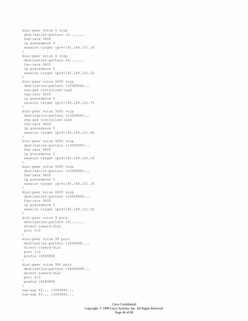
Cisco ConfidentialCopyright © 1998 Cisco Systems, Inc. All Rights Reserved.
Page 46 of 80
dial-peer voice 5 voipdestination-pattern +5.......fax-rate 9600ip precedence 5session target ipv4:192.168.121.18
!dial-peer voice 6 voip
destination-pattern +6.......fax-rate 9600ip precedence 5session target ipv4:192.168.121.20
!dial-peer voice 2000 voip
destination-pattern +12089882...req-qos controlled-loadfax-rate 9600ip precedence 5session target ipv4:192.168.121.74
!dial-peer voice 3000 voip
destination-pattern +13089883...req-qos controlled-loadfax-rate 9600ip precedence 5session target ipv4:192.168.121.66
!dial-peer voice 4000 voip
destination-pattern +14089884...fax-rate 9600ip precedence 5session target ipv4:192.168.121.19
!dial-peer voice 5000 voip
destination-pattern +15089885...fax-rate 9600ip precedence 5session target ipv4:192.168.121.18
!dial-peer voice 6000 voip
destination-pattern +16089886...fax-rate 9600ip precedence 5session target ipv4:192.168.121.20
!dial-peer voice 9 pots
destination-pattern +9.......direct-inward-dialport 0:D
!dial-peer voice 99 pots
destination-pattern +1808988....direct-inward-dialport 1:Dprefix 18089888
!dial-peer voice 999 pots
destination-pattern +18089888...direct-inward-dialport 2:Dprefix 18089888
!num-exp 82... 12089882...num-exp 83... 13089883...

Cisco ConfidentialCopyright © 1998 Cisco Systems, Inc. All Rights Reserved.
Page 47 of 80
num-exp 84... 14089884...num-exp 85... 15089885...num-exp 86... 16089886...num-exp 88... 18089888...!voice-port 0:D!voice-port 1:D!voice-port 2:D!interface Ethernet0
ip address 192.168.121.4 255.255.255.248!interface Serial0:23
no ip addressno ip mroute-cacheisdn incoming-voice modemno cdp enable
!interface Serial1:23
no ip addressno ip mroute-cacheisdn incoming-voice modemno cdp enable
!interface Serial2:23
no ip addressno ip mroute-cacheisdn incoming-voice modemno cdp enable
!interface FastEthernet0
no ip addressshutdownduplex full
!router eigrp 1
network 192.168.121.0redistribute connected
!no ip classlesssnmp-server community public RO!line con 0line aux 0line vty 0 4
password ciscologin
!scheduler interval 1000end

Cisco ConfidentialCopyright © 1998 Cisco Systems, Inc. All Rights Reserved.
Page 48 of 80
Austin 4700 WAN Aggregation Router
Current configuration:
!version 11.3no service password-encryption!hostname Austin_4700_WAN!enable secret ciscoenable password test!ip subnet-zero!!interface Ethernet0
ip address 192.168.121.5 255.255.255.248no mop enabled
!interface Ethernet1
no ip addressshutdown
!interface Ethernet2
no ip addressshutdown
!interface Ethernet3
no ip addressshutdown
!interface Ethernet4
no ip addressshutdown
!interface Ethernet5
no ip addressshutdown
!interface Serial0
ip address 192.168.121.73 255.255.255.248ip rtp header-compressionip rsvp bandwidth 1158 1158encapsulation pppno ip mroute-cachefair-queue 64 256 1000
!interface Serial1
ip address 192.168.121.65 255.255.255.248ip rtp header-compression
ip rsvp bandwidth 1158 1158encapsulation pppno ip mroute-cachefair-queue 64 256 1000

Cisco ConfidentialCopyright © 1998 Cisco Systems, Inc. All Rights Reserved.
Page 49 of 80
!interface Serial2
no ip addressshutdown
!interface Serial3
mtu 300no ip addressencapsulation frame-relay
!interface Serial3.100 multipoint
mtu 300ip address 192.168.121.17 255.255.255.240frame-relay map ip 192.168.121.18 20 broadcast CISCO rtp header-compression activeframe-relay map ip 192.168.121.19 30 broadcast CISCO rtp header-compression activeframe-relay map ip 192.168.121.20 40 broadcast CISCO rtp header-compression active
!interface Serial3.101 multipoint
mtu 300ip address 192.168.121.40 255.255.255.240frame-relay map ip 192.168.121.33 25 broadcast CISCO rtp header-compression activeframe-relay map ip 192.168.121.34 35 broadcast CISCO rtp header-compression activeframe-relay map ip 192.168.121.35 45 broadcast CISCO rtp header-compression active
!router eigrp 1
network 192.168.121.0!no ip classlessip route 192.168.121.18 255.255.255.255 Serial3.100ip route 192.168.121.19 255.255.255.255 Serial3.100ip route 192.168.121.20 255.255.255.255 Serial3.100ip route 192.168.121.80 255.255.255.248 192.168.121.35ip route 192.168.121.88 255.255.255.248 192.168.121.33ip route 192.168.121.96 255.255.255.248 192.168.121.34!!line con 0line aux 0line vty 0 4
password ciscologin
!end

Cisco ConfidentialCopyright © 1998 Cisco Systems, Inc. All Rights Reserved.
Page 50 of 80
San Diego Router (Frame Relay, 2 DLCIs)
Current configuration:
version 11.3no service password-encryption!hostname SanDiego_Router!enable secret cisco!ip subnet-zeroip domain-name Acme.comip name-server 192.168.6.1ip name-server 192.168.6.2!dial-peer voice 6000 pots
destination-pattern +16089886000port 1/0/0
!dial-peer voice 6001 pots
destination-pattern +16089886001port 1/0/1
!dial-peer voice 6002 pots
destination-pattern +16089886002port 1/1/0
!dial-peer voice 6003 pots
destination-pattern +16089886003port 1/1/1
!dial-peer voice 6 pots
destination-pattern +6port 2/0/0
!dial-peer voice 66 pots
destination-pattern +6port 2/0/1
!dial-peer voice 666 pots
destination-pattern +6port 2/1/0
!dial-peer voice 6666 pots
destination-pattern +6port 2/1/1
!dial-peer voice 2 voip
destination-pattern +2fax-rate 9600ip precedence 5session target ipv4:192.168.121.74
!dial-peer voice 3 voip
destination-pattern +3fax-rate 9600ip precedence 5session target ipv4:192.168.121.66
!

Cisco ConfidentialCopyright © 1998 Cisco Systems, Inc. All Rights Reserved.
Page 51 of 80
dial-peer voice 4 voipdestination-pattern +4fax-rate 9600ip precedence 5session target ipv4:192.168.121.19
!dial-peer voice 5 voip
destination-pattern +5fax-rate 9600ip precedence 5session target ipv4:192.168.121.18
!dial-peer voice 9 voip
destination-pattern +9fax-rate 9600ip precedence 5session target ipv4:192.168.121.4
!dial-peer voice 2000 voip
destination-pattern +12089882...fax-rate 9600ip precedence 5session target ipv4:192.168.121.74
!dial-peer voice 3000 voip
destination-pattern +13089883...fax-rate 9600ip precedence 5session target ipv4:192.168.121.66
!dial-peer voice 4000 voip
destination-pattern +14089884...fax-rate 9600ip precedence 5session target ipv4:192.168.121.19
!dial-peer voice 5000 voip
destination-pattern +15089885...fax-rate 9600ip precedence 5session target ipv4:192.168.121.18
!dial-peer voice 9000 voip
destination-pattern +18089888...fax-rate 9600ip precedence 5session target ipv4:192.168.121.4
!num-exp 82... 12089882...num-exp 83... 13089883...num-exp 84... 14089884...num-exp 85... 15089885...num-exp 86... 16089886...num-exp 88... 18089888...!voice-port 1/0/0
output attenuation 3!voice-port 1/0/1
output attenuation 3!voice-port 1/1/0

Cisco ConfidentialCopyright © 1998 Cisco Systems, Inc. All Rights Reserved.
Page 52 of 80
output attenuation 3!voice-port 1/1/1
output attenuation 3!voice-port 2/0/0
input gain 14!voice-port 2/0/1
input gain 13!voice-port 2/1/0
input gain 8!voice-port 2/1/1
input gain 11!interface Ethernet0/0
ip address 192.168.121.81 255.255.255.248no keepalive
!interface Serial0/0
mtu 300no ip addressencapsulation frame-relayno ip route-cacheno ip mroute-cachefair-queue 64 256 1000
!interface Serial0/0.1 point-to-point
mtu 300ip address 192.168.121.20 255.255.255.248no ip route-cacheno ip mroute-cacheframe-relay interface-dlci 140frame-relay ip rtp header-compression
!interface Serial0/0.2 point-to-point
mtu 300ip address 192.168.121.35 255.255.255.240no ip route-cacheno ip mroute-cacheframe-relay interface-dlci 145frame-relay ip rtp header-compression
!interface BRI0/0
no ip addressno ip mroute-cacheshutdown
!interface Ethernet0/1
no ip address!ip classlessip route 0.0.0.0 0.0.0.0 192.168.121.40ip route 192.168.121.4 255.255.255.255 192.168.121.17ip route 192.168.121.19 255.255.255.255 192.168.121.17ip route 192.168.121.18 255.255.255.255 192.168.121.17ip route 192.168.121.66 255.255.255.255 192.168.121.17ip route 192.168.121.74 255.255.255.255 192.168.121.17

Cisco ConfidentialCopyright © 1998 Cisco Systems, Inc. All Rights Reserved.
Page 53 of 80
!!snmp-server community public RO!line con 0line aux 0line vty 0 4 password cisco login!end

Cisco ConfidentialCopyright © 1998 Cisco Systems, Inc. All Rights Reserved.
Page 54 of 80
London Router (PPP, RTP, RSVP)
version 11.3no service password-encryption!hostname London!enable secret cisco!ip subnet-zeroip domain-name Acme.comip name-server 192.168.6.1ip name-server 192.168.6.2!dial-peer voice 3000 pots
destination-pattern +13089883…port 1/0/0prefix 83
!dial-peer voice 3001 pots
destination-pattern +13089883…port 1/0/1prefix 83
!dial-peer voice 3002 pots
destination-pattern +13089883…port 1/1/0prefix 83
!dial-peer voice 3003 pots
destination-pattern +13089883…port 1/1/1prefix 83
!dial-peer voice 3004 pots
destination-pattern +13089883…port 2/0/0prefix 83
!dial-peer voice 3005 pots
destination-pattern +13089883…port 2/0/1prefix 83
!dial-peer voice 3006 pots
destination-pattern +13089883…port 2/1/0prefix 83
!dial-peer voice 3007 pots
destination-pattern +13089883…port 2/1/1prefix 83
!dial-peer voice 3008 pots
destination-pattern +13089883…port 3/0/0prefix 83
!dial-peer voice 3009 pots

Cisco ConfidentialCopyright © 1998 Cisco Systems, Inc. All Rights Reserved.
Page 55 of 80
destination-pattern +13089883…port 3/0/1prefix 83
!dial-peer voice 3010 pots
destination-pattern +13089883…port 3/1/0prefix 83
!dial-peer voice 3011 pots
destination-pattern +13089883…port 3/1/1prefix 83
!dial-peer voice 3 pots
destination-pattern +3port 1/0/0
!dial-peer voice 31 pots
destination-pattern +3port 1/0/1
!dial-peer voice 32 pots
destination-pattern +3port 1/1/0
!dial-peer voice 33 pots
destination-pattern +3port 1/1/1
!dial-peer voice 34 pots
destination-pattern +3port 2/0/0
!dial-peer voice 35 pots
destination-pattern +3port 2/0/1
!dial-peer voice 36 pots
destination-pattern +3port 2/1/0
!dial-peer voice 37 pots
destination-pattern +3port 2/1/1
!dial-peer voice 38 pots

Cisco ConfidentialCopyright © 1998 Cisco Systems, Inc. All Rights Reserved.
Page 56 of 80
destination-pattern +3port 3/0/0
!dial-peer voice 39 pots
destination-pattern +3port 3/0/1
!dial-peer voice 310 pots
destination-pattern +3port 3/1/0
!dial-peer voice 311 pots
destination-pattern +3port 3/1/1
!dial-peer voice 2 voip
destination-pattern +2fax-rate 9600req-qos controlled-loadip precedence 5session target ipv4:192.168.121.74
!dial-peer voice 4 voip
destination-pattern +4fax-rate 9600ip precedence 5session target ipv4:192.168.121.19
!dial-peer voice 5 voip
destination-pattern +5fax-rate 9600ip precedence 5session target ipv4:192.168.121.18
!dial-peer voice 6 voip
destination-pattern +6fax-rate 9600ip precedence 5session target ipv4:192.168.121.20
!dial-peer voice 9 voip
destination-pattern +9fax-rate 9600req-qos controlled-loadip precedence 5session target ipv4:192.168.121.4
!dial-peer voice 2000 voip
destination-pattern +12089882...fax-rate 9600req-qos controlled-loadip precedence 5session target ipv4:192.168.121.74
!dial-peer voice 4000 voip
destination-pattern +14089884...fax-rate 9600ip precedence 5session target ipv4:192.168.121.19
!dial-peer voice 5000 voip
destination-pattern +15089885...fax-rate 9600ip precedence 5

Cisco ConfidentialCopyright © 1998 Cisco Systems, Inc. All Rights Reserved.
Page 57 of 80
session target ipv4:192.168.121.18!dial-peer voice 6000 voip
destination-pattern +16089886...fax-rate 9600ip precedence 5session target ipv4:192.168.121.20
!dial-peer voice 9000 voip
destination-pattern +18089888...fax-rate 9600req-qos controlled-loadip precedence 5session target ipv4:192.168.121.4
!num-exp 82... 12089882...num-exp 83... 13089883...num-exp 84... 14089884...num-exp 85... 15089885...num-exp 86... 16089886...num-exp 88... 18089888...!voice-port 1/0/0
operation 4-wiretype 5signal immediate
!voice-port 1/0/1
operation 4-wiretype 5signal immediate
!voice-port 1/1/0
operation 4-wiretype 5signal immediate
!voice-port 1/1/1
operation 4-wiretype 5signal immediate
!voice-port 2/0/0
operation 4-wiretype 5signal immediate
!voice-port 2/0/1
operation 4-wiretype 5signal immediate
!voice-port 2/1/0
operation 4-wiretype 5signal immediate
!voice-port 2/1/1
operation 4-wire

Cisco ConfidentialCopyright © 1998 Cisco Systems, Inc. All Rights Reserved.
Page 58 of 80
type 5signal immediate
!voice-port 3/0/0
operation 4-wiretype 5signal immediate
!voice-port 3/0/1
operation 4-wiretype 5signal immediate
!voice-port 3/1/0
operation 4-wiretype 5signal immediate
!voice-port 3/1/1
operation 4-wiretype 5signal immediate
!!interface Ethernet0/0
ip address 192.168.121.81 255.255.255.248!interface Serial0/0
ip address 192.168.121.66 255.255.255.248ip rtp header-compressionip rsvp bandwidth 1158 1158encapsulation pppno ip mroute-cachefair-queue 64 256 1000
!interface BRI0/0
no ip addressshutdown
!interface Ethernet0/1
no ip address

Cisco ConfidentialCopyright © 1998 Cisco Systems, Inc. All Rights Reserved.
Page 59 of 80
shutdown!router eigrp 1
network 192.168.121.0!no ip classless!snmp-server community public RO!line con 0line aux 0line vty 0 4
password ciscologin
!end
Configurations Explained:
This section will explain the portions of CLI having to do with Voice over IP.
Configuration Information for ACME Corporation
Austin 5300 Voice over IP Gateway Configuration
Current configuration:
!isdn switch-type primary-5ess!!controller T1 0
framing esfclock source internallinecode b8zspri-group timeslots 1-24
!dial-peer voice 3 voip
The dial-peer statement is used to map a particular telephony number or E.164 address to an IP address or physical port. The
number 3 is simply a placeholder and has only local significance. The Voice Over IP keyword is used to denote that this is a dial
peer that points to an IP address with which to establish an H.323 session.
destination-pattern +3.......
The destination pattern is simply the phone number for this particular dial peer. As shown, wild cards can be used.
req-qos controlled-load
This activates RSVP to request a controlled-load service when this dial peer is used.
fax-rate 9600
If a fax machine is used on for this particular dial peer it will be hard-coded to 9600 baud. This band can be set to 1200, 2400,
9600, and 14,400 baud. It is recommended to set the maximum allowable speed your fax machines can handle.
ip precedence 5
This sets the IP precedence of every voice packet using this dial peer to IP precedence 5 (critical)
session target ipv4:192.168.121.66

Cisco ConfidentialCopyright © 1998 Cisco Systems, Inc. All Rights Reserved.
Page 60 of 80
This is the IP address with which an H.323 session is made for this dial peer.
!dial-peer voice 6 voip
destination-pattern +6.......fax-rate 9600ip precedence 5session target ipv4:192.168.121.20
!dial-peer voice 3000 voip
destination-pattern +13089883...req-qos controlled-loadfax-rate 9600ip precedence 5session target ipv4:192.168.121.66
!dial-peer voice 6000 voip
destination-pattern +16089886...fax-rate 9600ip precedence 5session target ipv4:192.168.121.20
!dial-peer voice 9 potsThe keyword basic telephone service in the dial-peer statement signifies a local physical port.
destination-pattern +9.......direct-inward-dial
Direct-inward-dial tells the Cisco IOS software to use the incoming called number as the end destination number. (In other words,
If the called number is noted as 13089883000 in the Q.931 setup message, then that will be the final destination number and no
secondary dial tone will be given).
port 0:D
Since this configuration uses ISDN Primary Rate Interface (PRI), all call information will be received from the D channel.
!dial-peer voice 99 pots
destination-pattern +1808988....direct-inward-dialport 1:Dprefix 18089888
The prefix command is used to add a string of digits on any outgoing call placed through this dial-peer.
!num-exp 86... 16089886...
Number expansion is used to assist in shortening the numbering plan. Wild cards can also be used with number expansion.
!voice-port 0:D!voice-port 1:D!voice-port 2:D!interface Serial0:23
no ip addressno ip mroute-cacheisdn incoming-voice modem

Cisco ConfidentialCopyright © 1998 Cisco Systems, Inc. All Rights Reserved.
Page 61 of 80
In order for incoming voice calls to be answered by the voice over IP module in the Cisco 5300, this command must be used to send
the calls to the voice over IP carrier card.
no cdp enable!end
Austin Cisco 4700 WAN Aggregation Router
Current configuration:
!hostname Austin_4700_WAN!interface Serial1
ip address 192.168.121.65 255.255.255.248ip rtp header-compression
IP RTP enables RTP header compression.ip rsvp bandwidth 1158 1158
The IP RSVP bandwidth statement allocates the amount of bandwidth you want available for RSVP applications.
encapsulation pppno ip mroute-cachefair-queue 64 256 1000
This scenario enables WFQ on the interface.
!interface Serial2
no ip addressshutdown
!interface Serial3
mtu 300
The MTU must be set on the main interface; it is then carried down to the subinterface.
no ip addressencapsulation frame-relay
!interface Serial3.100 multipoint
mtu 300ip address 192.168.121.17 255.255.255.240frame-relay map ip 192.168.121.18 20 broadcast CISCO rtp header-compression activeframe-relay map ip 192.168.121.19 30 broadcast CISCO rtp header-compression activeframe-relay map ip 192.168.121.20 40 broadcast CISCO rtp header-compression active
This is a standard Frame Relay map statement, but it forces RTP header compression for these DLCIs.
!!no ip classlessip route 192.168.121.18 255.255.255.255 Serial3.100ip route 192.168.121.19 255.255.255.255 Serial3.100ip route 192.168.121.20 255.255.255.255 Serial3.100These static routes send any packet destined for a router to the voice DLCI’s.ip route 192.168.121.80 255.255.255.248 192.168.121.35ip route 192.168.121.88 255.255.255.248 192.168.121.33ip route 192.168.121.96 255.255.255.248 192.168.121.34
These static routes send any traffic destined for these networks to the data DLCIs.
!
end

Cisco ConfidentialCopyright © 1998 Cisco Systems, Inc. All Rights Reserved.
Page 62 of 80
San Diego Router (Frame Relay, 2 DLCIs)
version 11.3no service password-encryption!hostname SanDiegoRouter!dial-peer voice 9000 voip
destination-pattern +18089888...fax-rate 9600ip precedence 5session target ipv4:192.168.121.4
!voice-port 1/0/0
output attenuation 3Output attenuation on an FXS interface connecting to a handset shouldnormally be set to 3 dB.!voice-port 2/0/0
input gain 14
The input gain on a particular interface should be adjusted according to the “Voice Tuning” section explained earlier in this design
guide.
!interface Serial0/0
mtu 300no ip addressencapsulation frame-relayno ip route-cacheno ip mroute-cachefair-queue 64 256 1000
!interface Serial0/0.1 point-to-point
mtu 300ip address 192.168.121.20 255.255.255.248no ip route-cacheno ip mroute-cacheframe-relay interface-dlci 140frame-relay ip rtp header-compression
!ip classlessip route 0.0.0.0 0.0.0.0 192.168.121.40
There is no dynamic routing protocol on this network because bandwidth is preserved for actual voice and data. A static default
route is configured to send all traffic to the data DLCI.
ip route 192.168.121.4 255.255.255.255 192.168.121.17ip route 192.168.121.19 255.255.255.255 192.168.121.17ip route 192.168.121.18 255.255.255.255 192.168.121.17ip route 192.168.121.66 255.255.255.255 192.168.121.17ip route 192.168.121.74 255.255.255.255 192.168.121.17
Any traffic destined to a specific host router will be sent through the voice DLCI.
!end

Cisco ConfidentialCopyright © 1998 Cisco Systems, Inc. All Rights Reserved.
Page 63 of 80
London Router (PPP, RTP, RSVP)
version 11.3no service password-encryption!hostname London!!dial-peer voice 3000 pots
destination-pattern +13089883…port 1/0/0prefix 83
The prefix command allows a numerical string to be added to any outgoing called numbers on this interface.
!dial-peer voice 3001 pots
destination-pattern +13089883…port 1/0/1prefix 83
!dial-peer voice 3 pots
destination-pattern +3port 1/0/0

Cisco ConfidentialCopyright © 1998 Cisco Systems, Inc. All Rights Reserved.
Page 64 of 80
It is possible to use multiple dial peers to configure one interface. So in effect, one interface can have multiple dial peers attached
and give that interface multiple personalities.
!dial-peer voice 31 pots
destination-pattern +3port 1/0/1
!dial-peer voice 6 voip
destination-pattern +6fax-rate 9600ip precedence 5session target ipv4:192.168.121.20
!dial-peer voice 9 voip
destination-pattern +9fax-rate 9600req-qos controlled-load
Calls placed to the Cisco 5300 will request specific QoS using RSVP controlled-load service.
ip precedence 5session target ipv4:192.168.121.4
!voice-port 1/0/0operation 4-wire
This scenario configures this E&M interface to four- wire operation.
type 5
This command configures this E&M interface to use signal type V.
signal immediate
This command configures this E&M interface to use immediate signaling.
!end

Cisco ConfidentialCopyright © 1998 Cisco Systems, Inc. All Rights Reserved.
Page 65 of 80
Voice over IP miscellaneous Information and Specifications for Cisco 3600 Module
To determine the amount of bandwidth used across various topologies using various compression methods, see Table 5.
Note: Fax rates given were tested at 2400, 4800, and 9600 baud.
To determine the actual amount of bandwidth consumed by each encapsulation type matched with each codec type, use the
following formula:
Multiply byte count by 8 to obtain the bit count. Then multiply the result by 50 to obtain the bits per second.
Example:
G.729 with RTP Header Compression over Frame Relay
The chart gives a 28-byte frame. There are 8 bits in a byte.
28 x 8 = 224
The voice over IP implementation sends out a frame every 20 milliseconds; this is equivalent to 50 packets per second.
224 x 50 = 11,200 bps
or 11.2 kbps
This packet rate is for the voice traffic itself it does not count the H.323 setup, RSVP traffic, RTCP, or other protocol-related
information (Local Management Interface [LMI], PPP hello, and so on). This is the amount of bandwidth consumed if only one
speaker is talking and VAD is enabled. If speakers are talking at the same time or VAD is not utilized, then this 11.2-kbps stream
needs to be doubled. If background noise is significant enough, VAD is not able to distinguish the background noise from the speech,
and packets are transmitted, consuming backwidth, even though there is no speech.
Memory Information:
Cisco 3600 Voice over IP
• Static image size:
1 MB larger that non-voice over IP image of same name; most of the size increase is due to static tables in the Abstract Syntax
Notation One (ASN.1) code.
Processor Memory:
With voice and a small IP network, 18 MB of processor memory and 6 MB of I/O memory are sufficient; 32 MB is the recommended
amount for voice over IP and all plus images.
Allocated Memory:
• 20 KB per system + 3 KB per voice port
• 10 KB per active call
• 1.5 KB per call history record (includes both call legs)
• 2.5 KB per dial peer
Table 5 Packet Sizes with Various Compression Schemes and Topologies
— G.729 G.711 G.729 w/CRTP G.711 w/CRTP
Frame Relay 66-byte frame 206-byte frame 28-byte frame 168-byte frame
with fax 66-byte frame 66-byte frame 28-byte frame 28-byte frame
PPP 66-byte frame 206-byte frame 28-byte frame 168-byte frame
with fax 66-byte frame 66-byte frame 28-byte frame 28-byte frame
HDLC 66-byte frame 206-byte frame 28-byte frame 168-byte frame
with fax 66-byte frame 66-byte frame 28-byte frame 28-byte frame

Cisco ConfidentialCopyright © 1998 Cisco Systems, Inc. All Rights Reserved.
Page 66 of 80
Delay Information:
Table 6 is given to allow you to plan your voice network properly. If you know a specific link is going to add more delay than
suggested, you need to find another place in the network to make up for the lost time or adjust the quality expectation of the
customer.
Maximum configurable jitter buffer (playout buffer)
• G.711 voice—200 ms
• G.711 fax—300 ms
• G.729 voice—1360 ms
• G.729 fax—300 ms
Table 6 Delay Points in a Voice OVer IP Network
Delay Cause Description
~20 ms Coder delay Algorithmic delay plus processing delay with G.729
~20 ms Packetization/framing 2 x 10 ms frames
1–2 ms Move to I/O queue —
<10 ms Queue delay Varies, based upon congestion and priority scheme
~10 ms Access (up) link transmission Slow links cause greatest problems
<70 ms Backbone network transmission Physical limits, distance, speed of light
<10 ms Access (down) link transmission If end destination is slow bandwidth link
~1-2 ms Input queue to application —
~20-40 ms Jitter buffer This can be very large, depending upon network jitter
0 ms Coder processing delay Minimal with G.729
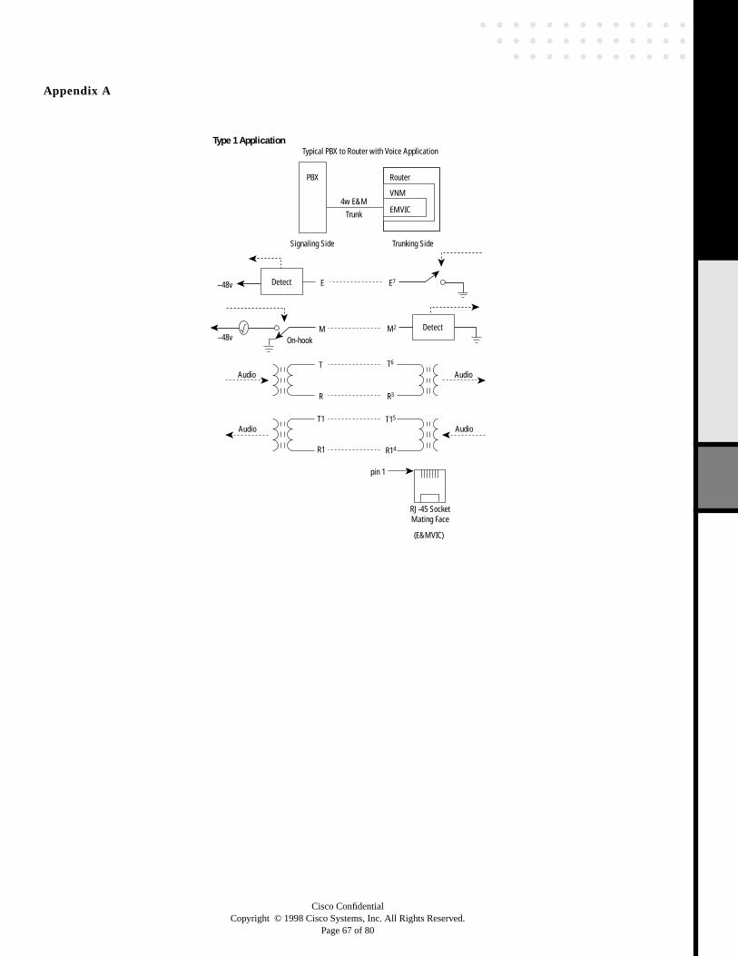
Cisco ConfidentialCopyright © 1998 Cisco Systems, Inc. All Rights Reserved.
Page 67 of 80
Appendix A
Router
VNM
EMVICTrunk
4w E&M
PBX
Signaling Side
Typical PBX to Router with Voice ApplicationType 1 Application
Trunking Side
–48v
–48v On-hook
E
pin 1
RJ-45 SocketMating Face
(E&MVIC)
E7
M2
R14
T15
R3
T6
Detect
Detect
Audio
Audio
M
T
R
T1
R1
Audio
Audio

Cisco ConfidentialCopyright © 1998 Cisco Systems, Inc. All Rights Reserved.
Page 68 of 80
Router
VNM
EMVICTrunk
4w E&M
PBX
Signaling Side
Typical PBX to Router with Voice ApplicationType 2 Application
Trunking Side
–48v
–48v
E
SG
pin 1
RJ-45 SocketMating Face(E&MVIC)
E7
M2
SB1
SG8
R14
T15
R3
T6
Detect
Audio
Audio
M
ptc
SB
T
R
T1
R1
Audio
Audio
Detect
Router
VNM
EMVICTrunk
E&M
C‘bank
Trunking Side
Back-to-Back Channel Bank to Router with Voice Application
Trunking Side
–48v –48v
E
SG
E7
M2
SB1
SG8
R14
T15
R3
T6
detect
Audio
Audio
M
ptcptc
SB
T
R
T1
R1
Audio
Audio
Detect Detect

Cisco ConfidentialCopyright © 1998 Cisco Systems, Inc. All Rights Reserved.
Page 69 of 80
Router
VNM
EMVICTrunk
E&M
PBX
Signaling Side
Typical PBX to Router with Voice ApplicationType 3 Application
Trunking Side
–48v
On-hook
–48vptc
E
pin 1
RJ-45 SocketMating Face
(E&MVIC)
E7
SG SG8
M2
R14
T15
R3
T6
Detect
Detect
Audio
Audio
M
SB1SB
T
R
T1
R1
Audio
Audio

Cisco ConfidentialCopyright © 1998 Cisco Systems, Inc. All Rights Reserved.
Page 70 of 80
Router
VNM
EMVICTrunk
E&M
PBX
Signaling Side
Typical PBX to Router with Voice ApplicationType 4 Application
Trunking Side
–48v
–48v
E
SG
pin 1
RJ-45 SocketMating Face(E&MVIC)
E7
M2
SB1
SG8
R14
T15
R3
T6
Detect
Audio
Audio
M
SB
T
R
T1
R1
–48v
Audio
Audio
Detect
Router
VNM
EMVICTrunk
E&M
C‘bank
Trunking Side
Back-to-Back Channel Bank to Router with Voice Application
Trunking Side
–48v
E
SG
E7
M2
SB1
SG8
R14
T15
R3
T6
detect
Audio
Audio
M
SB
T
R
T1
R1
Audio
Audio
Detect Detect

Cisco ConfidentialCopyright © 1998 Cisco Systems, Inc. All Rights Reserved.
Page 71 of 80
Router
VNM
EMVICTrunk
E&M
PBX
Signaling Side
Typical PBX to Router with Voice ApplicationType 5 Application
Trunking Side
–48v
–48v
–48v
E
pin 1
RJ-45 SocketMating Face
(E&MVIC)
E7
M2
R14
T15
R3
T6
Detect
Detect
Audio
Audio
M
T
R
T1
R1
Audio
Audio
Router
VNM
EMVICTrunk
E&M
C’bank
Back-to-Back Channel Bank to Router with Voice Application
Trunking SideTrunking Side
–48v
E E7
M2
R14
T15
R3
T6
Detect
Audio
Audio
M
T
R
T1
R1
Audio
Audio
Detect

Cisco ConfidentialCopyright © 1998 Cisco Systems, Inc. All Rights Reserved.
Page 72 of 80
Router
VNM
EMVICTrunk
E&M
PBX
Note that this typeshows that contactsare closed for on-hook,so the channel is busywhen the line breaks
Signaling Side
Typical PBX to Router with Voice Application
Type SSDC5A Application
Trunking Side
–48v
–48v
Eptc
pin 1
RJ-45 SocketMating Face
(E&MVIC)
E7
M2
R14
T15
R3
T6
Detect
Detect
Audio
Audio
M
T
R
T1
R1
Audio
Audio
Router
VNM
EMVICTrunk
E&M
C’bank
Back-to-Back Channel Bank to Router with Voice Application
Trunking SideTrunking Side
–48v–48v
E E7
M2
R14
T15
R3
T6
Detect Detect
Audio
Audio
M
T
R
T1
R1
Audio
Audio
On-hook
On-hook
On-hook
On-hook
ptcptc

Cisco ConfidentialCopyright © 1998 Cisco Systems, Inc. All Rights Reserved.
Page 73 of 80
Appendix B
Introduction
A fax over packet application enables the interworking of standard fax machines with packet networks. It accomplishes this by
extracting the fax image from an analog signal and carrying it as digital data over the packet network. This paper references a
general class of packet networks, since the modular software objects allow networks such as ATM, Frame Relay, and Internet (IP),
to be used to transport the fax. Currently, the Frame Relay Forum is the only packet network standards body that has defined a
protocol for transmission of fax over a packet network. However, the principles described are equally applicable to ATM and IP
networks.
An overview of a software architecture utilizing Embedded Communication Objects (ECOs) that supports fax over packet
applications is presented, and a system is described for sending fax image data and signaling information over the packet network.
ECOs are real-time software and hardware modules that can be dynamically configured to provide flexibility and scalability in
communication systems. Customers can gain a considerable advantage in time to market by using ECOs in building their
communication systems.
Applications
There are tremendous opportunities for cost savings by transmitting fax calls over packet networks. Fax data in its original form is
digital. However, it is modulated and converted to analog for transmission over the Public Swithced Telephone Network (PSTN).
This analog form uses 64 kbps of bandwidth in both directions.
The fax over packet interworking function (IWF) reverses this analog conversion, instead transmitting digital data over the
packet network, and then reconverting the digital data to analog for the receiving fax machine. This conversion process reduces the
overall bandwidth required to send the fax because the digital form is much more efficient and the fax transmission is half duplex
(that is, only one direction is used at any time). The peak rate for a fax transmission is 14.4 kbps in one direction. A representation
of this process is shown in Figure A-1.
This White Paper and the facsimile software described therein are provided by Telogy Networks to Cisco under license agreements from Telogy Networks. The White Paper and related software are Telogy Networks’ copyrighted materials, and are subject to restrictions in their respective license agreements and related non-disclosureobligations. This White Paper may not be modified without prior written permission from Telogy Networks, is for Cisco internal use only and may not be transferred to any third party.

Cisco ConfidentialCopyright © 1998 Cisco Systems, Inc. All Rights Reserved.
Page 74 of 80
Figure A-1 Fax Over Packet Conversion Process
An application for fax over packet, shown in Figure 2, is a network configuration of a company with numerous branch
offices that wants to use the packet network, instead of the long distance network, to provide fax access to the main office. The
Interworking Function (IWF) is the physical implementation of the hardware and software that enables the transmission of fax
over the packet network. It must support analog interfaces that directly interface to fax machines at the branches and to a PBX
at the central site. The Interworking Function must emulate the functions of a private branch exchange (PBX) for the fax machines.
Figure A-2 Fax Over Packet Application
PSTN Fax Call Procedure
This section describes the stages of a standard fax call over the PSTN so that the processing required for a reliable fax transmission
over a packet network can be explored. Fax machines in common use today implement the ITU T.30 and T.4 protocols. The T.30
protocol describes the formatting of nonpage data, such as messages that are used for capabilities negotiation. The T.4 protocol
describes formatting of page image data.
T.30 and T.4 have evolved substantially over time and are now quite complex because they attempt to describe the behavior of
an evolving set of fax machines. The timing related to the message interaction and phases of the call is critical and is one of the
major causes of problems in the transmission of fax over packet networks.
The PSTN fax call is divided into five phases, as shown in Figure A-3. This example assumes that the call is accomplished
without errors. The procedure becomes somewhat more complicated if errors occur or if there is a need for modem retraining.
The five phases include:
• Call establishment
• Control and capabilities exchange
Fax OverPacket
IWF
Fax OverPacket
IWF
Fax Fax
Fax in Analog Form Fax in Digital Form
Fax Over Packet Conversion Process
Fax in Analog Form
64 KbpsFull Duplex
14.4 KbpsHalf Duplex
64 KbpsFull Duplex
ATMFrame Relay
Internet
Home Offices
PBX
IWF
IWF
IWF
Fax
Fax Fax
Fax
PacketNetwork

Cisco ConfidentialCopyright © 1998 Cisco Systems, Inc. All Rights Reserved.
Page 75 of 80
• Page transfer
• End-of-page and multipage signaling
• Call release
Figure A-3 PSTN Fax Call Flow
Call Establishment
The fax call is established either through a manual process, where someone dials a call and puts the machine into fax mode, or by
automatic procedures, where no human interaction is required. In both cases, the answering fax machine returns an answer tone,
called a CED, which is the high-pitched tone that you hear when you call a fax machine. If the call is automatically dialed, the calling
station also indicates the fax call with a calling tone (CNG), which is a short, periodic tone that begins immediately after the number
is dialed. These tones are generated to allow a human participant to realize that a machine is present on the other end call. These
tones are sometimes used to recognize the presence of a fax call, although they are not a very reliable indication.
Control and Capabilities Exchange
The control and capabilities exchange phase of the fax call is used to identify the capabilities of the fax machine at the other end of
the call. It also negotiates the acceptable conditions for the call. The exchange of control messages throughout the fax call are sent
using the low-speed (300 bps) modulation mode.
PSTN Fax Call Flow
Offhook Dial
Answer
Legend
Low Speed Data
High Speed Data
Calling FaxMachine
Calling FaxMachine
Send Calling Tone (CNB) if automatic dialing
Send Called Station ID Tone (CED)
Send DCS (Optional NSF & CST)Preamble
Send DCS (Optional TSP)Preamble
High Speed Modem TrainingTCP
PreambleSend Confirmation to Recieve (CFR)
High Speed Modem Training
PreambleSend End of Page (EDP)
PreambleSend Message Confirmation (MCF)
PreambleSend Disconnect (DCN) Call Release
End of Pageand Multi-PageSignaling
Page Transfer
Control andCapabilitiesExchange
CallEstablishment
Fax Fax
Fax Page One

Cisco ConfidentialCopyright © 1998 Cisco Systems, Inc. All Rights Reserved.
Page 76 of 80
Every control message is preceded by a one-second preamble, which allows the communication channel to be conditioned for
reliable transmission.
The called fax machine begins the procedure by sending a Digital Identification Signal (DIS) message, which contains the
capabilities of the fax machine. An example of a capability that could be identified in this message is that the V.17 (14000-bps) data
signaling rate is supported. At the same time, the Called Subscriber Information (CSI) and Non-Standard Facilities (NSF) messages
are optionally sent. nonstandard facilities are capabilities that a particular fax manufacturer has built into a fax machine to
distinguish their product from others. They are not required to be supported for interoperability.
After the calling fax machine receives the DIS message, it determines the conditions for the call by examining its own
capabilities table. The calling machine responds with the digital command signal (DCS), which defines the conditions of the call.
At this stage, high-speed modem training begins. The high-speed modem is used in the next phase of the fax call to transfer
page data. The calling fax machine sends a training check field (TCF) through the modulation system to verify the training and
ensure that the channel is suitable for transmission at the accepted data rate. The called fax machine responds with a confirmation
to receive (CFR), which indicates that all capabilities and the modulation speed are confirmed and the fax page may be sent.
Page Transfer
The high-speed modem is used to transmit the page data that has been scanned in and compressed. It uses the ITU T.4 protocol
standard to format the page data for transmission over the channel.
End-of-Page and Multipage Signaling
After the page has been successfully transmitted, the calling fax machine sends an end-of-procedures (EOP) message if the fax call
is complete and all the pages have been transmitted. If only one page has been sent and there are additional ones to follow, it sends
a multipage signal (MPS). The called machine would responds with message confirmation (MCF) to indicate that the message has
been successfully received and it is ready to receive more pages.
Call Release
The release phase is the final phase of the call, where the calling machine sends a disconnect message (DCN). While the DCN
message is a positive indication that the fax call is over, it is not a reliable indication since the fax machine can disconnect
prematurely without ever sending the DCN message.
Quality of Service
The advantages of reduced cost and bandwidth savings of carrying fax over packet networks are associated with some quality of
service that which are unique to packet networks and can affect the reliability of the fax transmission. These issues are explored
next.
Timing
A major issue in the implementation of fax over packet networks is the problem of inaccurate timing of messages caused by delay
through the network. The delay of fax packets through a packet network causes the precise timing that is required for many portions
of the fax protocol to be skewed; this delay can result in the loss of the call. The fax over packet protocol in the interworking
function must compensate for the loss of a fixed timing of messages over the packet network so that the T.30 protocol operates
without error.
There are two sources of delay in an end-to-end fax over packet call: network delay and processing delay.
Network delay is caused by the physical medium and protocols that are used to transmit the fax data and by buffers used to
remove packet jitter on the receiving end. This delay is a function of the capacity of the links in the network and the processing that
occurs as the packets transit the network. The jitter buffers add delay when they remove the packet delay variation of each packet
as it transits the packet network. This delay can be a significant part of the overall delay since packet delay variations can be as high
as 70 to 100 msec in some Frame Relay networks, and even higher in IP networks.

Cisco ConfidentialCopyright © 1998 Cisco Systems, Inc. All Rights Reserved.
Page 77 of 80
Processing delay is caused by the process of demodulating and collecting the digital fax information into a packet for
transmission over the packet network. The encoding delay is a function of both the processor execution time and the amount of
data collected before sending a packet to the network. Low-speed data, for instance, is usually sent out with a single byte per packet
since the time to collect a byte of information at 300 bps is 30 milliseconds.
Jitter
Delay issues are compounded by the need to remove jitter, a variable interpacket timing caused by the network that a packet
traverses. An approach to removing the jitter is to collect packets and hold them long enough so that the slowest packets to arrive
are still in time to be played in the correct sequence. This approach, however, causes additional delay. In most fax over packet
protocols, a time stamp is incorporated in the packet to ensure that the information is played out at the proper instant.
Lost Packet Compensation
Lost packets can be an even more severe problem, depending on the type of packet network that is being used. In a voice over packet
application, the loss of packets can be addressed by replaying last packets and other methods of interpolation. A fax over packet
application, however, has more severe constraints on the loss of data since the fax protocol can fail if information is lost. This
problem varies depending on the type of fax machine used and whether the error correction mode is enabled.
Two schemes that are used by fax over packet software to address the problems of lost frames follow:
• Repeating information in subsequent frames so that the error can be corrected by the receiver’s playout mechanism
• Using an error-correcting protocol such as TCP to transport the fax data at the expense of added delay
Fax over Packet Software Architecture
The facsimile interface unit (FIU) is the software ECO that resides within a fax over packet interworking function. It demodulates
voice-band signals from an analog interface and converts them to a digital format that is suitable for transport over a packet
network. It also remodulates data received from the packet network and transmits it to the analog interface. In doing so, the FIU
performs protocol conversion between group 3 facsimile protocols and the digital facsimile protocol employed over the packet
network.
The fax interface unit, shown in Figure A-4, consists of the following three units:
Fax modem unit frequency modulation [FM]: processes pulse code modulation (PCM) samples based on the current
modulation mode and supports the following functions:
• V.21 channel 2 (300-bps) binary signaling modulation and demodulation
• High-Level Data Link Control (HDLC) framing (0-bit insertion/removal, cyclic redundancy check (CRC) generation/checking)
• V.27 ter (2400/4800-bps) high-speed data modulation and demodulation
• V.29 (7200/9600-bps) high-speed data modulation and demodulation
• V.17 (14,390-bps) high-speed data modulation
• CED detection and generation
• CNG detection and generation
• V.21 channel 2 detection

Cisco ConfidentialCopyright © 1998 Cisco Systems, Inc. All Rights Reserved.
Page 78 of 80
Figure A-4 Fax Over Packet Module
The fax protocol unit (FP) compensates for the effects of timing and lost packets caused by the packet network. The FP prevents
the local fax machine from timing out while waiting for a response from the other end by generating HDLC flags. If, after a timeout,
the response from the remote fax machine is not received, it also sends a CRP frame (command repeat) to resend the frame. This
unit monitors the facsimile transaction timing, the direction of current transmission, and the proper modem configuration. It
performs:
• Protocol processing (group 3 facsimile)
• Examination/alteration of binary signaling messages to ensure compatibility of the facsimile transfer with the constraints of the
transmission channel
• Network channel interface data formatting
• Line state transitions
The fax network driver unit (FND) assembles and disassembles fax packets to be transmitted over the network and is the interface
unit between the FP and the network modules. The fax packets are formatted to be carried as a voice payload to the network
modules. The control information packets consist of header and time stamp information. In the direction of the pulse code
modulation (PCM) to the packet network, the FND collects the specified number of bytes and transmits the packet to the network.
In the receive direction, the FND provides data with the proper timing (as generated on the transmit side and reproduced through
the received time-stamp information) to the rest of the FIU. The FND delays the data in order to remove timing jitter from the packet
arrival times and performs:
• Formatting of control information
• Formatting of fax data
• Properly timed playout of data
• Elastic (slip) buffering
Fax Summary
A fax over packet software architecture using Embedded Communication Objects (ECOs) has been described for the interworking
of fax machines and packet networks. Some of the key features enabling this application to function successfully follow:
• An approach that addresses the effect of delay through the network
• A process that minimizes the effect of jitter
• Features that address lost packet compensation
Though the quality of service issues associated with carrying fax over packet networks are significant, the future of this approach
will be driven by the substantial cost savings and exciting applications made possible with fax over packet software technology.
PCMInterface
Real TimeOperating
Environment
ControlUnit
FaxModem
Unit
FaxProtocol
Unit
Fax Interface Unit (FIU)
Fax Over Packet Module
FaxNetwork
DriverUnit
PacketVoice
ProtocolFaxTo PacketNetwork
SerialPort

Cisco ConfidentialCopyright © 1998 Cisco Systems, Inc. All Rights Reserved.
Page 79 of 80
End of Appendix B and the Telogy Fax over Packet white paper.
Summary
This design implementation guide has covered a very broad and far-reaching topic known as packet voice. This guide has covered
the basics in H.323, voice, fax, packet voice, and fax as well as the necessary quality-of-service information to design the next level
in voice networks. This however, is just the beginning of what you will need to learn to design, implement, and deploy these
next-generation voice networks. For more information, see the suggested reading list.
Suggested Reading
Pecar, Telecommunications Factbook.
McGraw-Hill; (sbn: 0-07-049183-6).
Good detail on PBX networks, PSTN, and analog and digital technology
Bezar, LAN Times Guide to Telephony.
McGraw-Hill; (isbn: 0-07-882126-6).
A mixture of CTI, telephony, and data communications
Telephony Reference Books:
Newton, Newton’s Telecom Dictionary; 12th ed.
Flatiron Publishing isbn; (isbn: 1-57820-008-3).
Minoli, Telecommunications Technology Handbook
Artech House; (isbn: 0-89006-425-3).
Freeman, Telecommunication System Engineering; third ed.
Wiley; (isbn: 0-471-13302-7.)
Freeman, Reference Manual for Telecommunications Engineering, second ed.
Wiley; (isbn: 0-471-57960-2.)
Cover almost everything in the telco world; the next level up/down is then the ITU specifications.
Books by detailed topic:
Schaphorst, Videoconferencing & Videotelephony: Technology & Standards.
Artech House (isbn: 0-89006-844-5)
Details of H.320, H.323, H.324
Trulove, A guide to fractional T1.
Artech House; (isbn: 0-89006-524-1).
Black, The V Series Recommendations.
McGraw-Hill; (isbn: 0-07-005592-0).
Everything you need to know about V.x modem, ISDN standards
Kessler, ISDN; Concepts, Facilities and Services; 3rd ed.
McGraw-Hill; (isbn: 0-07-034249-0)
ISDN in detail, including relationship to ATM, Frame Relay, SMDS,...
Russell, Signaling System #7.
McGraw-Hill; (isbn: 0-07-054991-5).
Ginsburg, ATM; Solutions for enterprise interworking.
Addison-Wesley; (isbn: 0-201-87701-5)
Excellent ATM 101 to detailed, with good historical overview

Copyright © 1998 Cisco Systems, Inc. All rights reserved. Printed in USA. Cisco IOS is a trademark, and Catalyst, Cisco, Cisco Systems, and the Cisco Systems logo are registered trademarks of Cisco Systems, Inc.in the U.S. and certain other countries. All other trademarks mentioned in this document are the property of their respective owners. 9802R 3/98LW
Cisco Systems has more than 200 offices in the following countries. Addresses, phone numbers, and fax numbers are listed on the
C i s c o C o n n e c t i o n O n l i n e We b s i t e a t h t t p : / / w w w. c i s c o . c o m .
Argentina • Australia • Austria • Belgium • Brazil • Canada • Chile • China (PRC) • Colombia • Costa Rica • Czech Republic • DenmarkEngland • France • Germany • Greece • Hungary • India • Indonesia • Ireland • Israel • Italy • Japan • Korea • Luxembourg • MalaysiaMexico • The Netherlands • New Zealand • Norway • Peru • Philippines • Poland • Portugal • Russia • Saudi Arabia • Scotland •
Singapore
Corporate HeadquartersCisco Systems, Inc.170 West Tasman DriveSan Jose, CA 95134-1706USAhttp://www.cisco.comTel: 408 526-4000
800 553-NETS (6387)Fax: 408 526-4100
European HeadquartersCisco Systems Europe s.a.r.l.Parc Evolic, Batiment L1/L216 Avenue du QuebecVillebon, BP 70691961 Courtaboeuf CedexFrancehttp://www-europe.cisco.comTel: 33 1 6918 61 00Fax: 33 1 6928 83 26
AmericasHeadquartersCisco Systems, Inc.170 West Tasman DriveSan Jose, CA 95134-1706USAhttp://www.cisco.comTel: 408 526-7660Fax: 408 527-0883
Asia HeadquartersNihon Cisco Systems K.K.Fuji Building, 9th Floor3-2-3 MarunouchiChiyoda-ku, Tokyo 100Japanhttp://www.cisco.comTel: 81 3 5219 6250Fax: 81 3 5219 6001
Recognition
There were many people responsible for contributing to this guide. I would like to thank James Murphy, Mike Knappe, Cary
Fitzgerald, Tony Gallagher, David Oran, Fred Baker, Gavin Jin, Herb Wildfeur, Mark Rumer, Jas Jain, and Mark Monday for their
contributions to this design guide. I would also like to thank Telogy Networks for allowing use of their Fax over Packet White paper
in this guide.


![[VoIP] Cisco CallManager Basics (VoIP)](https://img.pdfslide.us/doc/110x75/55cf99c3550346d0339f0d92/voip-cisco-callmanager-basics-voip.jpg)