Embed Size (px)
Citation preview
Ref: NR/L3/SIG/10179 Issue: 3 Date: 03/12/2011 Compliance date: 03/12/2011
Page 2 of 79
Issue record
Issue Date Comments 2 April 2006 2nd Issue
Supersedes RT/E/C/10179 ‘Set Up and Maintenance of Adjustable Stretcher Bars – A Good Practice Guide
3 December 2011 Renumbered to NR/L3/SIG/10179. 3rd issue Updates for:- Set up calculation of adjustable stretcher bars Torque setting Minimum actions Use of Ellipse asset condition module
Compliance
This Network Rail standard is mandatory and shall be complied with by Network Rail and its contractors if applicable from 03 December 2011.
When this standard is implemented, it is permissible for all projects that have formally completed GRIP Stage 3 (Option Selection) to continue to comply with the issue of any relevant Network Rail standards current when GRIP Stage 3 was completed and not to comply with requirements contained herein, unless stipulated otherwise in the scope of this standard.
Ref: NR/L3/SIG/10179 Issue: 3 Date: 03/12/2011 Compliance date: 03/12/2011
Page 3 of 79
Reference documentation
NR/L3/SIG/11303 Signalling Installation Handbook
NR/L2/SIG/10663
NR/SMS/PF01
Signalling Maintenance Specifications
Point Fittings
NR/L2/SIG/30014 Signal Works Testing
NR/L3/SIG/11231 Signalling Maintenance Testing
NR/WI/SIG/00111 Points General – Supplementary Drives – Mechanical
NR/GN/SIG/11772 Supplementary Point Drives & Detection
RE/PW/586 35mm Adjustable Stretcher Bar (Full-depth Switches Plain Lead) General Arrangement Type 1 Brackets
RE/PW/587 35mm Adjustable Stretcher Bar (Full-depth Switches Plain Lead) General Arrangement Type 2 Brackets
RE/PW/588 35mm Adjustable Stretcher Bar (Full-depth Switches Plain Lead) General Arrangement Type 3 Brackets
RE/PW/586 35mm Adjustable Stretcher Bar (Full-depth Switches Plain Lead) General Arrangement Type 4 Brackets
RE/PW/586 35mm Adjustable stretcher Bar (Full-depth Switches Plain Lead) General Arrangement Type 5 Brackets
RE/PW/814 General Arrangement of Adjustable 35mm square Stretcher Bars for shallow depth switches
RE/PW/823 General Arrangement of Adjustable 35mm square Stretcher Bars for shallow depth switch diamonds
RE/PW/824 Brackets and fixings for Adjustable 35mm square Stretcher Bars for shallow depth switches and switch diamonds
RE/PW/92/113A Stretcher Bars and Soleplates for BS113A/CEN56E1 (inclined) Switch Diamonds
Disclaimer
In issuing this document for its stated purpose, Network Rail makes no warranties, express or implied, that compliance with all or any documents it issues is sufficient on its own to ensure safe systems of work or operation. Users are reminded of their own duties under health and safety legislation.
Supply
Copies of documents are available electronically, within Network Rail’s organisation. Hard copies of this document may be available to Network Rail people on request to the relevant controlled publication distributor. Other organisations may obtain copies of this document from IHS. Tel: 01344 328039.
Ref: NR/L3/SIG/10179 Issue: 3 Date: 03/12/2011 Compliance date: 03/12/2011
Page 4 of 79
Contents
1 Purpose 5 2 Scope 5 3 Definitions 6 4 Responsibilities 11 5 Introduction to Adjustable Stretcher Bars 16 6 Adjustable Stretcher Bar Tooling 26 7 Installation and Set Up 30 8 Maintenance 44 9 Problem Solving 48
Appendix A Adjustable Stretcher Bar Defect Form 49 Appendix B SM(T) Points gauge, FWC and RSO Measurement form TEF 3074 50 Appendix C - Adjustable Stretcher Bar brackets for Turnouts 51 Appendix D - Lock Stretcher Bars 53 Appendix E - Hardlock nut & Type 2 Bracket fastener ordering details 55 Appendix F - MGL Pin Tooling 56 Appendix G - Extracts from RE/PW Drawings 57 Appendix H - Switch Rail Openings 60 Appendix I - Minimum Actions for Adjustable Stretcher Bar Assembly Defects 64
Ref: NR/L3/SIG/10179 Issue: 3 Date: 03/12/2011 Compliance date: 03/12/2011
Page 5 of 79
1 Purpose
This standard specifies the, technical instructions, maintenance specifications, and responsibilities for the installation, inspection and response to defects associated with adjustable stretcher bar assemblies.
2 Scope
This Network Rail standard applies to the installation and management of adjustable stretcher bar assemblies, the management of lock stretcher bar assemblies, their associated fastenings and defects on all S&C point switches fitted with 35mm square section Adjustable Stretcher Bars on the following rail sections CEN56 (BS113A) full depth switches, RT60 shallow depth switches and CEN54 (UIC54B) shallow depth switches including plain leads and switch diamonds in running lines.
Other S&C components not covered by this standard are managed in accordance with existing standards.

Ref: NR/L3/SIG/10179 Issue: 3 Date: 03/12/2011 Compliance date: 03/12/2011
Page 6 of 79
3 Definitions
Toe
5
Planing
HeelMoveable Length
1 2 3
4
6
7
8 109
1. Sole Plate (Stock Rail Gauge Tie)
3. 2nd & Subsequent stretcher bars
5. Optimum Toe Opening 108mm (See NR/SMS/Part Z /02)
7. Right hand Stock RailRight hand Switch Rail
9. Heel
2. 1st Stretcher bar
4. Minimum Free Wheel Clearance of 50mm - CEN54, 60mm - CEN60
6. Left hand Stock RailLeft hand Switch Rail
8. Slide base plates
10. Stress Transfer Blocks
Figure 1 – Terminology
Adjustable Stretcher Bar Assembly A 35mm square sectioned bar, threaded at each end fitted with rubber bushes and secured to fixing brackets with M30 lock-nuts. The function of a Stretcher Bar is to couple together the switch rails, transmit the drive forces and enable adjustment of the switch opening;
Bracket Fasteners The fasteners used to secure the Adjustable Stretcher Bar brackets to the rail, e.g. torque prevailing nut fastener or multi-groove locking pin (Huck pin) or Kep nut
Broken The adjustable stretcher bar bracket has broken if the bracket is in two separate pieces.
CEN54E1A1 The current designation of the shallow depth switch rails used in Shallow Depth Vertical S&C, formerly know as UIC54B.
CEN 56 rail Full depth flat bottom rail section
NOTE an imperial equivalent of this section is BS113A. These can be identified by "56E1" and "113A" relief branding marks on the rail webs respectively.
Ref: NR/L3/SIG/10179 Issue: 3 Date: 03/12/2011 Compliance date: 03/12/2011
Page 7 of 79
CEN60 RT60 & NR60
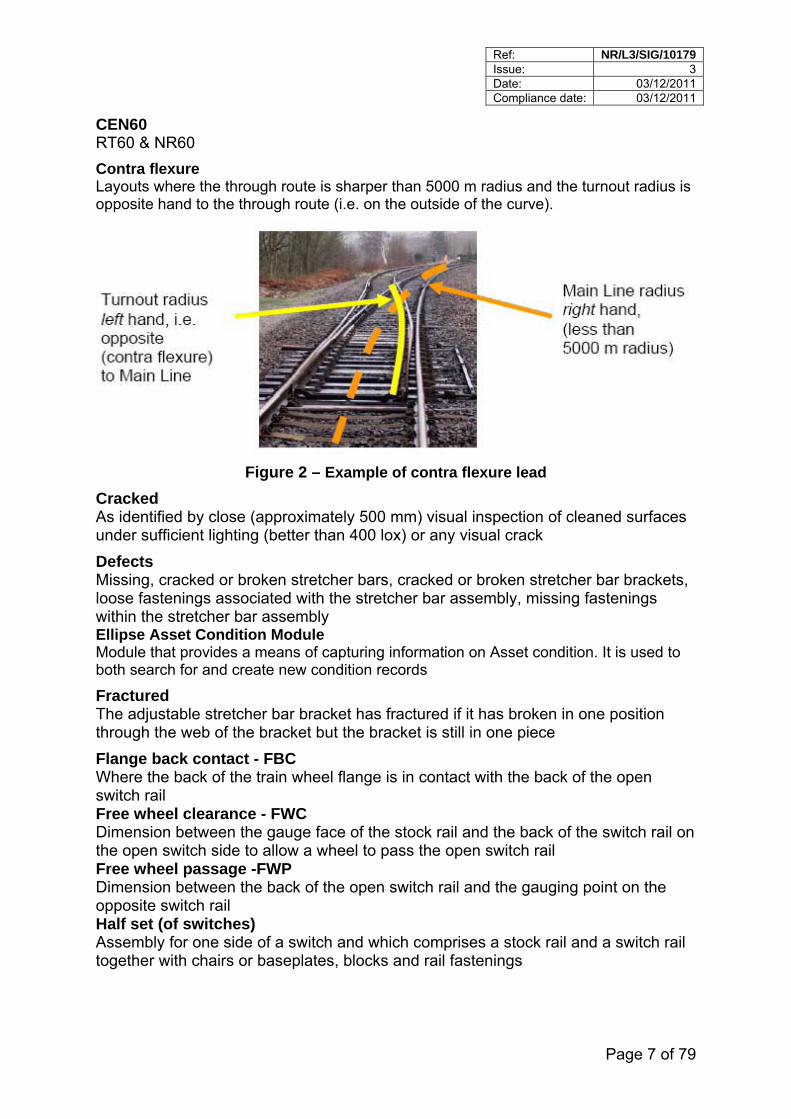
Contra flexure Layouts where the through route is sharper than 5000 m radius and the turnout radius is opposite hand to the through route (i.e. on the outside of the curve).
Figure 2 – Example of contra flexure lead
Cracked As identified by close (approximately 500 mm) visual inspection of cleaned surfaces under sufficient lighting (better than 400 lox) or any visual crack
Defects Missing, cracked or broken stretcher bars, cracked or broken stretcher bar brackets, loose fastenings associated with the stretcher bar assembly, missing fastenings within the stretcher bar assembly Ellipse Asset Condition Module Module that provides a means of capturing information on Asset condition. It is used to both search for and create new condition records
Fractured The adjustable stretcher bar bracket has fractured if it has broken in one position through the web of the bracket but the bracket is still in one piece
Flange back contact - FBC Where the back of the train wheel flange is in contact with the back of the open switch rail Free wheel clearance - FWC Dimension between the gauge face of the stock rail and the back of the switch rail on the open switch side to allow a wheel to pass the open switch rail Free wheel passage -FWP Dimension between the back of the open switch rail and the gauging point on the opposite switch rail Half set (of switches) Assembly for one side of a switch and which comprises a stock rail and a switch rail together with chairs or baseplates, blocks and rail fastenings
Ref: NR/L3/SIG/10179 Issue: 3 Date: 03/12/2011 Compliance date: 03/12/2011
Page 8 of 79
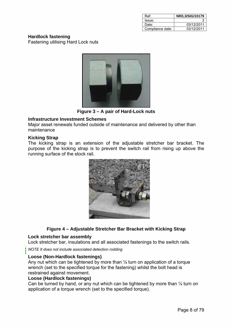
Hardlock fastening Fastening utilising Hard Lock nuts
Figure 3 – A pair of Hard-Lock nuts
Infrastructure Investment Schemes Major asset renewals funded outside of maintenance and delivered by other than maintenance
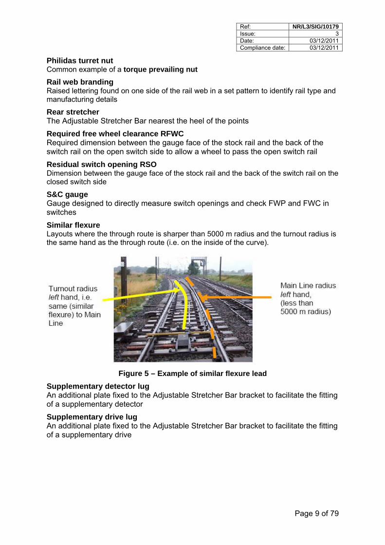
Kicking Strap The kicking strap is an extension of the adjustable stretcher bar bracket. The purpose of the kicking strap is to prevent the switch rail from rising up above the running surface of the stock rail.
Figure 4 – Adjustable Stretcher Bar Bracket with Kicking Strap
Lock stretcher bar assembly Lock stretcher bar, insulations and all associated fastenings to the switch rails.
NOTE It does not include associated detection rodding
Loose (Non-Hardlock fastenings) Any nut which can be tightened by more than ¼ turn on application of a torque wrench (set to the specified torque for the fastening) whilst the bolt head is restrained against movement. Loose (Hardlock fastenings) Can be turned by hand, or any nut which can be tightened by more than ¼ turn on application of a torque wrench (set to the specified torque).
Ref: NR/L3/SIG/10179 Issue: 3 Date: 03/12/2011 Compliance date: 03/12/2011
Page 9 of 79
Philidas turret nut Common example of a torque prevailing nut
Rail web branding Raised lettering found on one side of the rail web in a set pattern to identify rail type and manufacturing details
Rear stretcher The Adjustable Stretcher Bar nearest the heel of the points
Required free wheel clearance RFWC Required dimension between the gauge face of the stock rail and the back of the switch rail on the open switch side to allow a wheel to pass the open switch rail
Residual switch opening RSO Dimension between the gauge face of the stock rail and the back of the switch rail on the closed switch side
S&C gauge Gauge designed to directly measure switch openings and check FWP and FWC in switches
Similar flexure Layouts where the through route is sharper than 5000 m radius and the turnout radius is the same hand as the through route (i.e. on the inside of the curve).
Figure 5 – Example of similar flexure lead
Supplementary detector lug An additional plate fixed to the Adjustable Stretcher Bar bracket to facilitate the fitting of a supplementary detector
Supplementary drive lug An additional plate fixed to the Adjustable Stretcher Bar bracket to facilitate the fitting of a supplementary drive
Ref: NR/L3/SIG/10179 Issue: 3 Date: 03/12/2011 Compliance date: 03/12/2011
Page 10 of 79
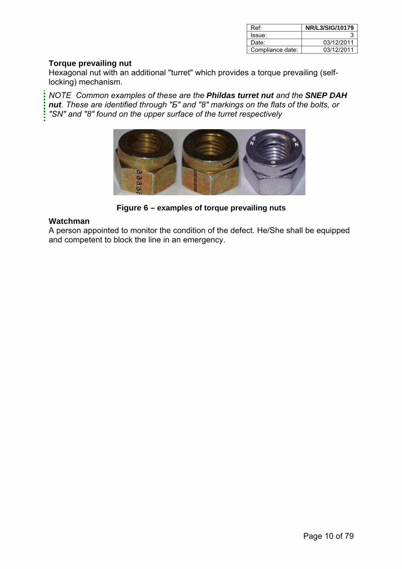
Torque prevailing nut Hexagonal nut with an additional "turret" which provides a torque prevailing (self-locking) mechanism.
NOTE Common examples of these are the Phildas turret nut and the SNEP DAH nut. These are identified through "Б" and "8" markings on the flats of the bolts, or "SN" and "8" found on the upper surface of the turret respectively
Figure 6 – examples of torque prevailing nuts
Watchman A person appointed to monitor the condition of the defect. He/She shall be equipped and competent to block the line in an emergency.
Ref: NR/L3/SIG/10179 Issue: 3 Date: 03/12/2011 Compliance date: 03/12/2011
Page 11 of 79
4 Responsibilities
4.1 Track patrollers
Track patrollers shall be responsible for the visual inspection of the adjustable stretcher bar assembly, lock stretcher bar assembly and all associated fastenings. They shall record and report any defects using form TEF 3015 as specified in NR/L2/TRK/001/A01. This inspection shall be undertaken as part of the basic visual inspection of S&C.
Loose fastenings shall be established by visual inspection.
NOTE Typical indications of looseness are rust marks, witness marks in deposits (grease or grime) or shiny surfaces caused by rubbing or visual evidence that the nut or bolt has moved.
The looseness of the fastening shall be verified by touch.
Loose fastenings shall be reported using the standard location convention, as specified in the NR/L2/TRK/001/D.
Track patrollers shall take the appropriate action to protect traffic if necessary, as specified in NR/L2/TRK/001/A01
4.2 Section Manager (Track) – SM(T)
SM(T) shall be responsible for the visual inspection of the adjustable stretcher bar assembly, lock stretcher bar assembly and all associated fastenings during the supervisors visual track inspection. They shall measure gauge, free wheel clearance, residual switch opening, Flange Back Contact (FBC) (where required) and take any necessary action as specified in NR/L2/TRK/001/D. This inspection and associated measurements shall be undertaken as part of the supervisor's visual inspection of S&C. Alternative inspection arrangements may be made in complex layouts.
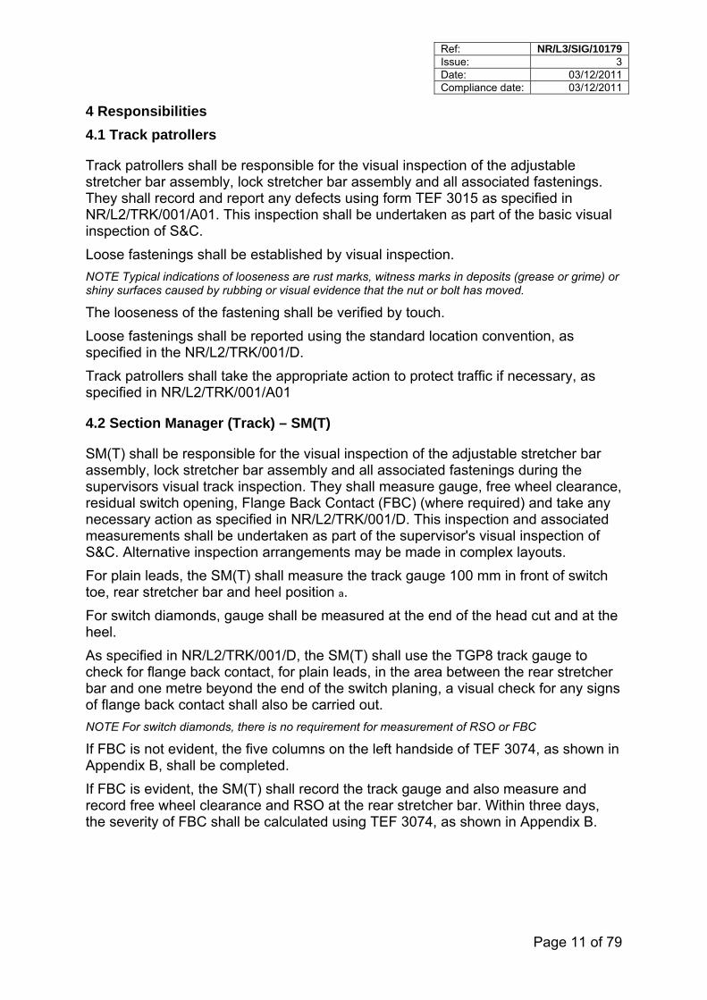
For plain leads, the SM(T) shall measure the track gauge 100 mm in front of switch toe, rear stretcher bar and heel position a.
For switch diamonds, gauge shall be measured at the end of the head cut and at the heel.
As specified in NR/L2/TRK/001/D, the SM(T) shall use the TGP8 track gauge to check for flange back contact, for plain leads, in the area between the rear stretcher bar and one metre beyond the end of the switch planing, a visual check for any signs of flange back contact shall also be carried out.
NOTE For switch diamonds, there is no requirement for measurement of RSO or FBC
If FBC is not evident, the five columns on the left handside of TEF 3074, as shown in Appendix B, shall be completed.
If FBC is evident, the SM(T) shall record the track gauge and also measure and record free wheel clearance and RSO at the rear stretcher bar. Within three days, the severity of FBC shall be calculated using TEF 3074, as shown in Appendix B.
Ref: NR/L3/SIG/10179 Issue: 3 Date: 03/12/2011 Compliance date: 03/12/2011
Page 12 of 79
If theoretical FBC is established, the SM(T) shall agree with the SM(S) the actions necessary to validate the condition and take actions in accordance with NR/L2/TRK/001/D01 Inspection and maintenance of permanent way – Specific requirements for switches and crossings.
The SM(T) shall record any defects using TEF 3022 , Supervisor Track Inspection Record.
Loose fastenings shall be reported using the standard location convention specified in NR/L2/TRK/001/D and TEF 3099, adjustable stretcher bar assembly defect form, as shown in Appendix A. This form shall be forwarded to the System Support Manager (SSM), who shall arrange for the data to be recorded into the Ellipse Asset Condition Module.
The SM(T) is responsible for compliance to the timescales mandated on Track Staff in NR/L2/TRK/001/D, or apply the mandated mitigation measures.
The SM(T) shall support the SM(S) in the investigation into the cause of defective components.
The SM(T) shall order replacement switches to the required dimensions and radii and install them to the gauge tolerances laid down in this standard.
To enable the installation of new adjustable stretcher bars in accordance with Section 7, the SM(T) shall be responsible for track gauge being measured by competent personnel and dimensions provided to the Signalling technicians installing the adjustable stretcher bars.
Following the installation of new stretcher bars, the SM(T) shall record the installed dimensions, after a period of traffic using TEF 3074, as shown in Appendix B, during the next scheduled SM(T) inspection.
a These checks and measurements are required on the higher speed route through the S&C, reducing the need for the switches to be operated during the SM(T) inspection. Measurements for the lower speed route through the S&C are only required if the sidewear to the switch rail beyond the end of the head planing on the lower speed route is more severe than the sidewear to the switch rail beyond the end of the head planing on the higher speed route. NOTE The SM(T) is informed of the fitting of new stretcher bars by the SM(S), as specified in 4.5.
SM(T) duties for the purpose of this standard may also be carried out by an Assistant SM(T) or technical staff with adequate competencies as assessed by the Track Maintenance Engineer.
The SM(T) shall be responsible for actioning any track work arising items generated by Ellipse.
Ref: NR/L3/SIG/10179 Issue: 3 Date: 03/12/2011 Compliance date: 03/12/2011
Page 13 of 79
4.3 Track Maintenance Engineer (TME)
The TME shall review the findings and approve the actions following investigations into defective components.
This will include assisting the S&TME with completing the relevant SINCS processes for multiple or repeat failures.
Where further investigation into the cause of defects is undertaken and additional track actions are implemented, the TME shall monitor and review the effectiveness of the actions.
The TME shall assess the competencies of any Assistant SM(T) or Technical staff if they are delegated to undertake any of the SM(T) duties.
The TME shall routinely review the Ellipse asset condition module (ACM) reports for their S&C assets to confirm the required remedial work has been undertaken and that the ACM is updated accordingly.
4.4 Signalling Technician
The Signalling Technician shall be responsible for the detailed inspection (as laid down in NR/SMS/PF01) of the adjustable stretcher bar assembly, lock stretcher bar assembly and associated fastenings.
Any loose fastenings shall be actioned in accordance with Appendix I Minimum Actions for Adjustable Stretcher Bar Defects and recorded on TEF 3099, Adjustable Stretcher bar assembly defect form, as shown in Appendix A. This form shall be forwarded to the SM(S) and the data shall be recorded in the Ellipse Asset Condition Module.
The Signalling Technician shall check FWC and FWP using the S&C Gauge at the rear stretcher bar and at any supplementary drive positions. FWP shall also be checked at the point of minimum FWC, this is normally found beyond the rear stretcher bar position.
The Signalling Technician shall measure RSO at the same locations. All measurements shall be recorded on the PF01 record card in accordance with NR/SMS/PF01. The Signalling Technician shall check visually for flange back contact. The Signalling Technician is responsible for replacing loose, cracked, broken, fractured or missing stretcher bar assemblies and lock stretcher bar assembly fastenings.
Once rectification work has been undertaken e.g. to tighten loose fastenings or replace a cracked stretcher bar bracket TEF 3099 shall be completed to indicate that the work has been carried out.
Signalling Technicians are responsible for fitting and adjusting stretcher bars and lock stretcher bars. Any track gauge variance to the nominal value (1432 mm for vertical S&C, 1435 mm for inclined S&C) shall be taken into account when fitting the replacement adjustable stretcher bar assembly in accordance with Section 7 Installation and Set up.
After fitting new stretcher bars, the Signalling Technician shall advise the SM(S).
Ref: NR/L3/SIG/10179 Issue: 3 Date: 03/12/2011 Compliance date: 03/12/2011
Page 14 of 79
NOTE The SM(S) can be informed the new stretchers bars have been fitted via Ellipse The Signalling Technician shall be responsible for measuring and recording the switch toe opening. This is recorded on the NR/SMS/FPL record card.
The Signalling Technician shall undertake any follow up actions as required by Appendix I Minimum Actions for Adjustable Stretcher Bar Defects.
4.5 Section Manger (Signals) - SM(S)
SM(S) is responsible for the visual inspection of the adjustable stretcher bar assembly, lock stretcher bars and associated fastenings during Level 2 inspections, in accordance with NR/L2/SIG/10028. They shall visually check for flange back contact during these inspections.
It is the responsibility of the SM(S) to periodically check FWC, FWP and RSO measurements during supervisory inspections. The S&C Gauge may be used to take these measurements. This information shall be recorded as specified in NR/SMS/PF01 on the PF01 Record Card. Any sub-standard conditions identified shall be investigated.
The SM(S) shall action, record and report any defects as specified in Appendix I Minimum Actions for Adjustable Stretcher Bar Defects. Loose fastenings shall be reported using the standard location convention as indicated on TEF 3099, Adjustable Stretcher bar assembly defect form, as shown in Appendix A.
The SM(S) shall be responsible for compliance to the timescales mandated on Signalling Staff in the Appendix I Minimum Actions for Adjustable Stretcher Bar Defects, or applying the mandated mitigation measures. The SM(S) shall arrange for competent personnel to measure track gauge prior to the replacement of the stretcher bar assembly.
Any track gauge variance shall be taken into account by signal technicians fitting replacement stretcher bars in accordance with Section 7 Installation and Set up.
After new stretcher bars have been fitted, the SM(S) shall advise the SM(T).
The SM(S) shall lead in the investigation into the cause of defective components as set out in Appendix I, supported by the SM(T) as appropriate.
SM(S) duties for the purpose of this standard may also be delegated to Signalling Technical Support Staff with adequate competencies, as agreed with the S&TME.
The SM(S) shall be responsible for actioning any signalling work arising items generated by Ellipse, and for the completion of TEF 3099 once work has been completed. This shall indicate the current condition of the asset and detail the work that has been completed. This information shall be entered into the Ellipse Asset Condition Module within seven days.
4.6 Signal and Telecoms Maintenance Engineer (S&TME)
The S&TME, supported by the TME, shall review the findings and approve the actions following investigations into defective components, including the review and closure of SINCS files in accordance with NR/L2/SIG/10047, and repeat right-side failures in accordance with NR/L3/SIG/SG0139.

Ref: NR/L3/SIG/10179 Issue: 3 Date: 03/12/2011 Compliance date: 03/12/2011
Page 15 of 79
Where further investigation into the cause of defects is undertaken and additional signalling actions are implemented, the S&TME shall monitor and review the effectiveness of the actions.
The S&TME shall agree any delegation of the SM(S) activities to Signalling Technical Support Staff.
When complete renewal of switches is undertaken, the layout shall conform to this specification before acceptance back into maintenance by the S&TME.
The S&TME shall routinely review the Ellipse asset condition module (ACM) reports for their S&C assets to confirm the required remedial work has been undertaken and that the ACM is updated accordingly.
4.7 Fault Controller
Fault Controllers shall be responsible for logging any faults reported in FMS and notifying the Signal Faulting Technician, the SM(S) and SM(T) of the existence of the fault and requirement for action.
As required by NR/L2/SIG/10047, Fault Controllers shall be responsible for opening a SINCS file after an incident, including the allocation of an appropriate hazard rating.
4.8 Infrastructure Investment Schemes
Where Infrastructure Investment schemes install S&C with adjustable stretcher bars, as part of a Project or Track Renewal the manufacture, installation and commissioning of the works shall comply with the requirements of this standard.
Network Rail's routine maintenance inspections of the installed S&C and any arising actions shall be managed in accordance with the Asset Management Plan (AMP) applicable to the works.
All S&C which falls within the scope of this standard shall conform to these requirements, regardless of the GRIP stage of the scheme.
NOTE “Manufacture” means the initial assembly of bearers, switches, stretcher bars, point operating equipment and associated hardware into the designed configuration.
4.9 Section Planners and Section Administrators
Section Planners and Section Administrators shall be responsible for entering the information from forms TEF 3015, TEF 3022, TEF 3074, TEF 3099 and appropriate WAIFs into the Ellipse Asset Condition Module within seven days of recording.
Ref: NR/L3/SIG/10179 Issue: 3 Date: 03/12/2011 Compliance date: 03/12/2011
Page 16 of 79
5 Introduction to Adjustable Stretcher Bars
This section explains the various parts that are used to make up the Adjustable Stretcher Bar assembly, their function and how some parts differ to cater for rail profile, point drive and other issues.
5.1 Adjustable Stretcher Bars
The primary function of an Adjustable Stretcher Bar is to couple together the switch rails, transmit the drive forces, and enable adjustment of the switch opening (free wheel clearance) throughout the planed length of the switch.
The fundamental safety feature of hardlock nuts is that they lock against each other not the bushes.
Rubber bushes provide some flexibility for the switch rail/Adjustable Stretcher Bar assembly to aid movement. They also provide electrical insulation.
When correctly installed and adjusted the closed switch rail shall fit up to the stock rail such that Facing Point Lock and Detection Tests can be achieved.
5.1.1 Lubrication of Threads
IMPORTANT: The security of the Adjustable Stretcher Bar depends on lock-nuts running freely on the Adjustable Stretcher Bar threads prior to tightening.
If for any reason the lock-nuts don’t run freely a new or refurbished Adjustable Stretcher Bar shall be used.
Lubricating the exposed threads on Adjustable Stretcher Bars is prudent since it protects the threads against corrosion
Care shall be taken when applying the lubricant to the exposed threads that no lubricant is applied to the faces of Hard-Lock nuts or the rubber bushes
Any lubrication applied on the Hardlock nuts could reduce effectiveness of their locking action and grease applied to the rubber bushes could cause the rubber to de-grade and potentially cause the bushes to fail. The correct type of lubricant to use on Adjustable Stretcher Bar threads is Rocol Clamp Lock Lubricant (027/025095)
5.1.2 Refurbishment of Adjustable Stretcher Bars
New Adjustable Stretcher Bars are available pre-fitted with bushes, brackets and Hardlock nuts.
Adjustable stretcher bars may be recovered and refurbished locally.
Refurbishment is:
complete dismantlement of the bar,
disposal of nuts, bolts, bushes and Hard Lock nuts
retention of the bar and brackets,
Ref: NR/L3/SIG/10179 Issue: 3 Date: 03/12/2011 Compliance date: 03/12/2011
Page 17 of 79
wire brushing of the threaded portion of the bar (the threaded portion may be lightly lubricated using Rocol Clamp Lock Lubricant (027/025095) if necessary),
supply of new bolts, bushes and Hard-Lock nuts,
visual inspection of the threaded portion for damaged or worn threads prior to re-use,
visual inspection of the brackets for cracks and distortion prior to re-use (brackets that are cracked or distorted shall be scrapped),
reassembly.
Where a stretcher bar has been removed from track as a result of a fracture or break in one of the brackets, the other bracket on the adjustable stretcher bar assembly shall not be re-used.
Where necessary use a wire brush and a detergent based cleaner to remove dirt and grease.
Refurbishment shall only be carried out in workshop conditions. Refurbished stretcher bars shall be re-assembled in accordance with this standard and the relevant RE/PW drawing.
5.2 M30 Lock Nuts
Adjustable Stretcher Bar lock-nuts secure the Adjustable Stretcher Bar to the fixing brackets. There are two types of lock nuts used to secure Adjustable Stretcher Bars and the following describes the two different types used.
5.2.1 Full-nut/half-nut lock nuts
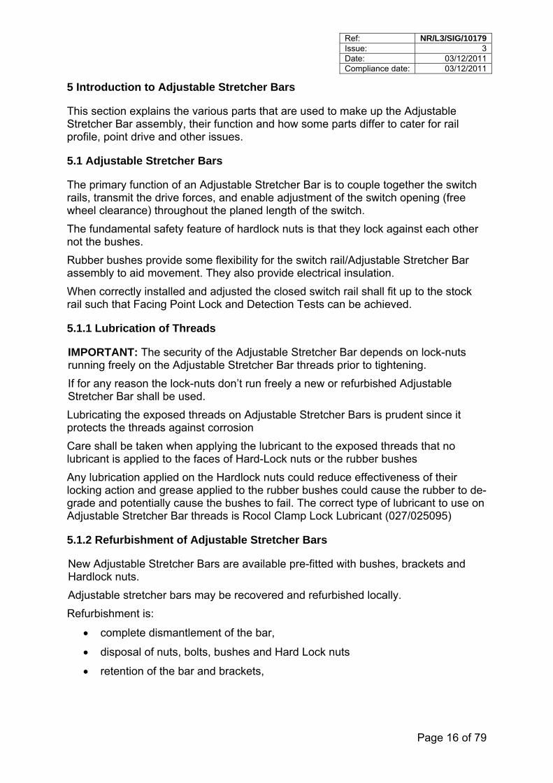
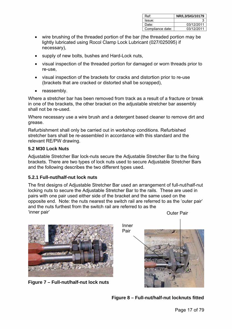
The first designs of Adjustable Stretcher Bar used an arrangement of full-nut/half-nut locking nuts to secure the Adjustable Stretcher Bar to the rails. These are used in pairs with one pair used either side of the bracket and the same used on the opposite end. Note: the nuts nearest the switch rail are referred to as the ‘outer pair’ and the nuts furthest from the switch rail are referred to as the ‘inner pair’ Outer Pair
Figure 7 – Full-nut/half-nut lock nuts
Inner Pair
Figure 8 – Full-nut/half-nut locknuts fitted
Ref: NR/L3/SIG/10179 Issue: 3 Date: 03/12/2011 Compliance date: 03/12/2011
Page 18 of 79
The full-nut is fitted nearest to the bush which is tightened a third-of-a-turn, sufficient to compress the bush. The half-nut is then fitted against the full-nut which together performs the lock-nut function (see 6.1 for torque settings).
This design is now non-preferred and any new installations shall use Hard Lock nuts
5.2.2 Hard Lock Nuts
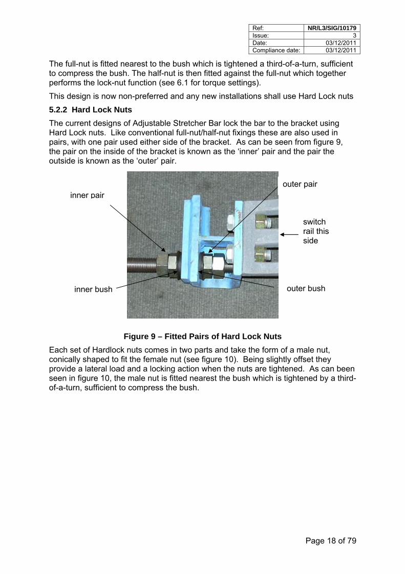
The current designs of Adjustable Stretcher Bar lock the bar to the bracket using Hard Lock nuts. Like conventional full-nut/half-nut fixings these are also used in pairs, with one pair used either side of the bracket. As can be seen from figure 9, the pair on the inside of the bracket is known as the ‘inner’ pair and the pair the outside is known as the ‘outer’ pair.
switch rail this side
inner bush outer bush
inner pair outer pair
Figure 9 – Fitted Pairs of Hard Lock Nuts
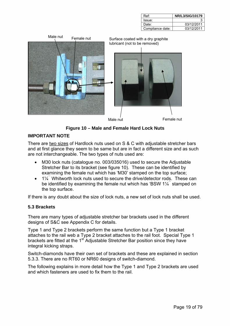
Each set of Hardlock nuts comes in two parts and take the form of a male nut, conically shaped to fit the female nut (see figure 10). Being slightly offset they provide a lateral load and a locking action when the nuts are tightened. As can been seen in figure 10, the male nut is fitted nearest the bush which is tightened by a third-of-a-turn, sufficient to compress the bush.
Ref: NR/L3/SIG/10179 Issue: 3 Date: 03/12/2011 Compliance date: 03/12/2011
Page 19 of 79
Male nut Female nut
Male nut
Surface coated with a dry graphite lubricant (not to be removed)
Female nut
Figure 10 – Male and Female Hard Lock Nuts
IMPORTANT NOTE
There are two sizes of Hardlock nuts used on S & C with adjustable stretcher bars and at first glance they seem to be same but are in fact a different size and as such are not interchangeable. The two types of nuts used are:
M30 lock nuts (catalogue no. 003/035016) used to secure the Adjustable Stretcher Bar to its bracket (see figure 10). These can be identified by examining the female nut which has ‘M30’ stamped on the top surface;
1¼´´ Whitworth lock nuts used to secure the drive/detector rods. These can be identified by examining the female nut which has ‘BSW 1¼´´ stamped on the top surface.
If there is any doubt about the size of lock nuts, a new set of lock nuts shall be used.
5.3 Brackets
There are many types of adjustable stretcher bar brackets used in the different designs of S&C see Appendix C for details.
Type 1 and Type 2 brackets perform the same function but a Type 1 bracket attaches to the rail web a Type 2 bracket attaches to the rail foot. Special Type 1 brackets are fitted at the 1st Adjustable Stretcher Bar position since they have integral kicking straps.
Switch-diamonds have their own set of brackets and these are explained in section 5.3.3. There are no RT60 or NR60 designs of switch-diamond.
The following explains in more detail how the Type 1 and Type 2 brackets are used and which fasteners are used to fix them to the rail.
Ref: NR/L3/SIG/10179 Issue: 3 Date: 03/12/2011 Compliance date: 03/12/2011
Page 20 of 79
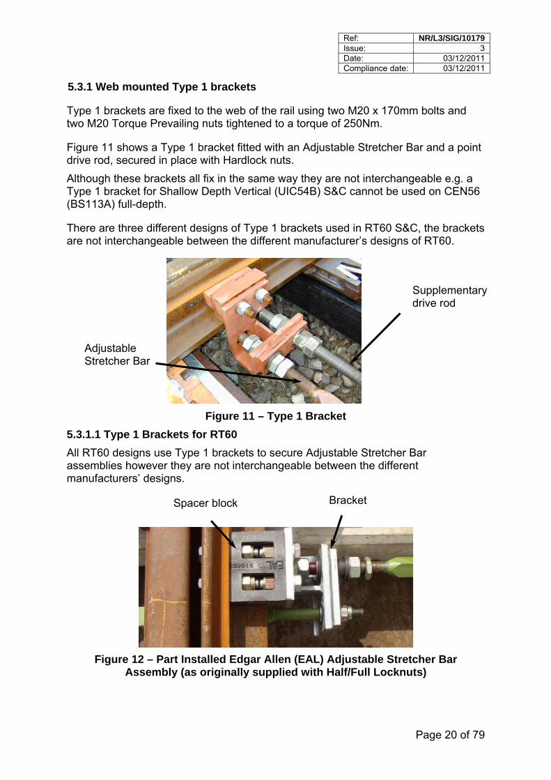
5.3.1 Web mounted Type 1 brackets
Type 1 brackets are fixed to the web of the rail using two M20 x 170mm bolts and two M20 Torque Prevailing nuts tightened to a torque of 250Nm.
Figure 11 shows a Type 1 bracket fitted with an Adjustable Stretcher Bar and a point drive rod, secured in place with Hardlock nuts.
Although these brackets all fix in the same way they are not interchangeable e.g. a Type 1 bracket for Shallow Depth Vertical (UIC54B) S&C cannot be used on CEN56 (BS113A) full-depth.
There are three different designs of Type 1 brackets used in RT60 S&C, the brackets are not interchangeable between the different manufacturer’s designs of RT60.
Supplementary drive rod
Adjustable Stretcher Bar
Figure 11 – Type 1 Bracket
5.3.1.1 Type 1 Brackets for RT60
All RT60 designs use Type 1 brackets to secure Adjustable Stretcher Bar assemblies however they are not interchangeable between the different manufacturers’ designs.
Spacer block Bracket
Figure 12 – Part Installed Edgar Allen (EAL) Adjustable Stretcher Bar Assembly (as originally supplied with Half/Full Locknuts)
Ref: NR/L3/SIG/10179 Issue: 3 Date: 03/12/2011 Compliance date: 03/12/2011
Page 21 of 79
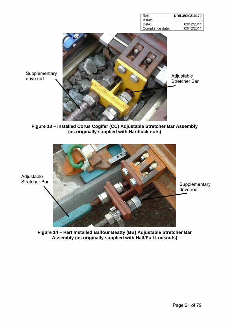
Figure 13 – Installed Corus Cogifer (CC) Adjustable Stretcher Bar Assembly (as originally supplied with Hardlock nuts)
Figure 14 – Part Installed Balfour Beatty (BB) Adjustable Stretcher Bar Assembly (as originally supplied with Half/Full Locknuts)
Supplementary drive rod
Adjustable Stretcher Bar
Adjustable Stretcher Bar Supplementary
drive rod
Ref: NR/L3/SIG/10179 Issue: 3 Date: 03/12/2011 Compliance date: 03/12/2011
Page 22 of 79
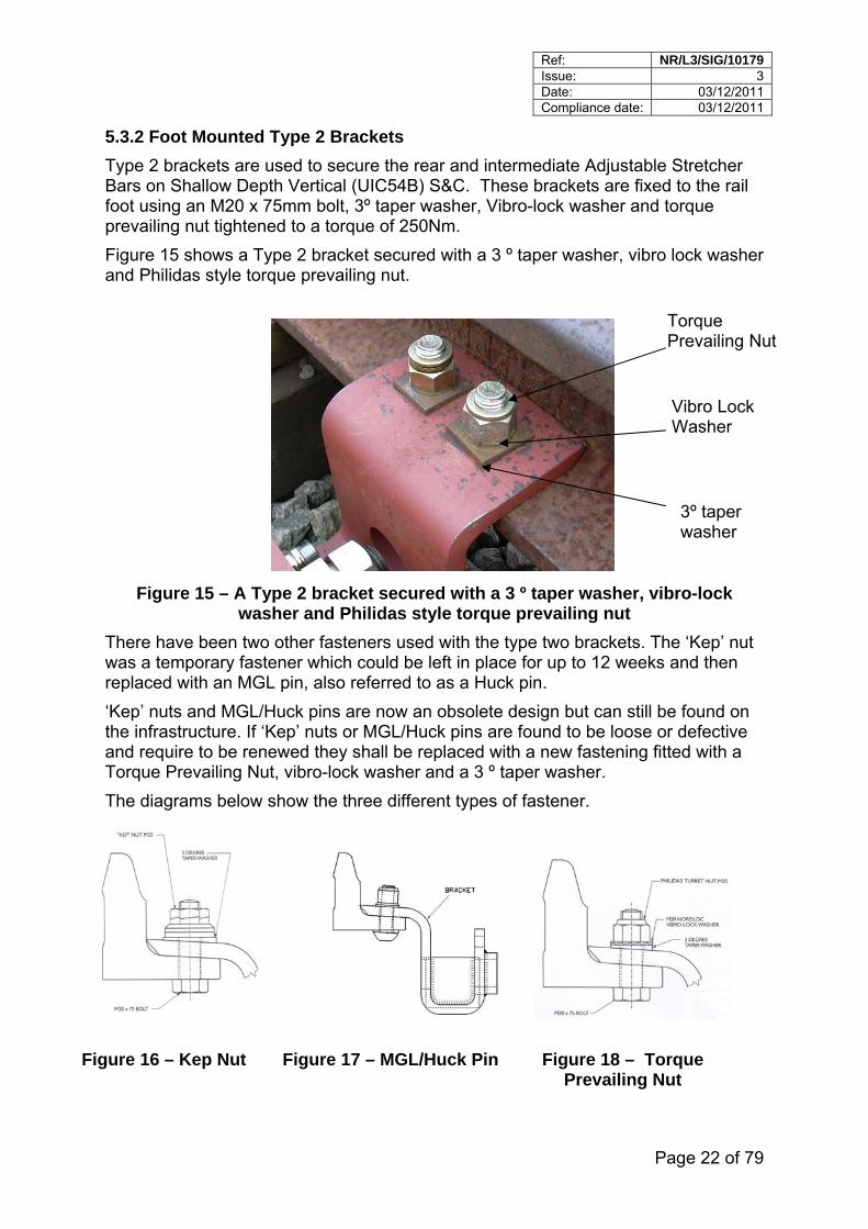
5.3.2 Foot Mounted Type 2 Brackets
Type 2 brackets are used to secure the rear and intermediate Adjustable Stretcher Bars on Shallow Depth Vertical (UIC54B) S&C. These brackets are fixed to the rail foot using an M20 x 75mm bolt, 3º taper washer, Vibro-lock washer and torque prevailing nut tightened to a torque of 250Nm.
Figure 15 shows a Type 2 bracket secured with a 3 º taper washer, vibro lock washer and Philidas style torque prevailing nut.
Torque Prevailing Nut
Vibro Lock Washer
3º taper washer
Figure 15 – A Type 2 bracket secured with a 3 º taper washer, vibro-lock washer and Philidas style torque prevailing nut
There have been two other fasteners used with the type two brackets. The ‘Kep’ nut was a temporary fastener which could be left in place for up to 12 weeks and then replaced with an MGL pin, also referred to as a Huck pin.
‘Kep’ nuts and MGL/Huck pins are now an obsolete design but can still be found on the infrastructure. If ‘Kep’ nuts or MGL/Huck pins are found to be loose or defective and require to be renewed they shall be replaced with a new fastening fitted with a Torque Prevailing Nut, vibro-lock washer and a 3 º taper washer.
The diagrams below show the three different types of fastener.
Figure 16 – Kep Nut Figure 17 – MGL/Huck Pin Figure 18 – Torque Prevailing Nut
Ref: NR/L3/SIG/10179 Issue: 3 Date: 03/12/2011 Compliance date: 03/12/2011
Page 23 of 79
Note: Type 2 brackets can also be found on RT60 manufactured by S&C VAE. It is also possible to use Type 2 brackets on CEN56 (BS113A) full depth switches but the application is limited.
5.3.3 Brackets for Switch Diamonds
Switch diamond designs exist for CEN56 (BS113A) and CEN54E1A1 (UIC54B) rail profiles. There are currently no designs for RT60 or NR60.
CEN56 (BS113A) full depth switch-diamonds use a fixed Stretcher Bar design and are not covered in this Standard (see Track Engineering Drawing RE/PW/92/113A ‘Stretcher Bars and Soleplates for Switch-diamonds’).
Shallow Depth Vertical (UIC54B) switch-diamonds have in total four Adjustable stretchers bars. The type of brackets used and the position of the stretcher bar in the switch depends on whether the switch-diamonds are point machine driven or Clamp-lock driven.
The following is an overview of switch-diamonds for shallow depth CEN54E1A1 (UIC54B) rail, for full details see Track Engineering Drawings: RE/PW/823, ‘General Arrangement for Switch-diamonds’ and RE/PW/824, ‘Brackets and Fixings for Adjustable 35mm square Adjustable Stretcher Bars for Shallow-depth switches’.
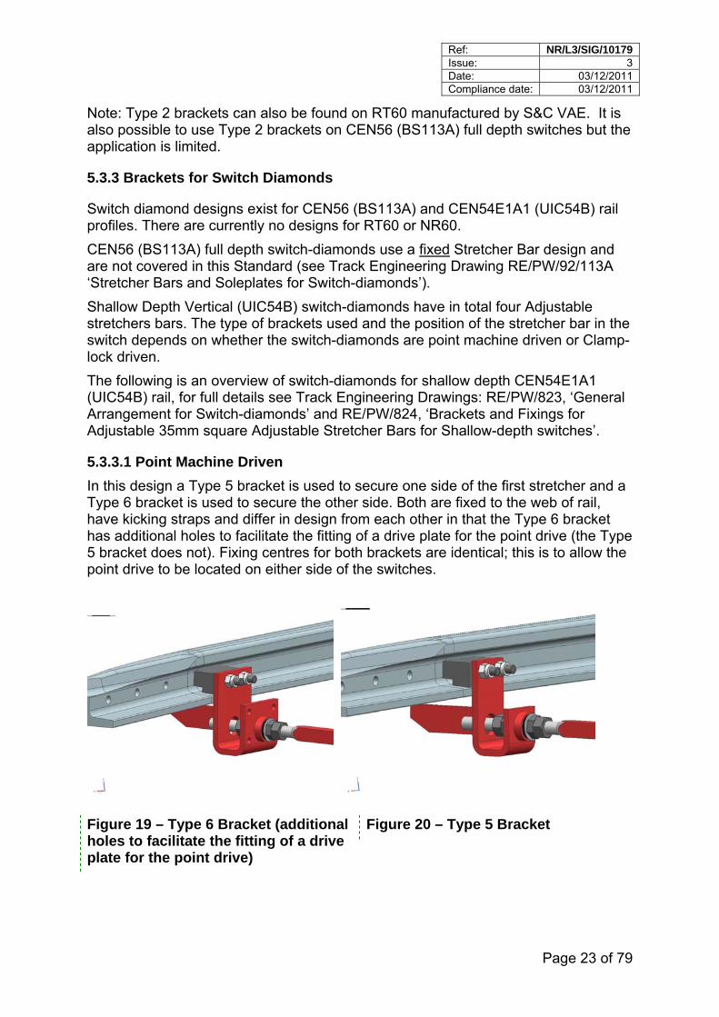
5.3.3.1 Point Machine Driven
In this design a Type 5 bracket is used to secure one side of the first stretcher and a Type 6 bracket is used to secure the other side. Both are fixed to the web of rail, have kicking straps and differ in design from each other in that the Type 6 bracket has additional holes to facilitate the fitting of a drive plate for the point drive (the Type 5 bracket does not). Fixing centres for both brackets are identical; this is to allow the point drive to be located on either side of the switches.
Figure 19 – Type 6 Bracket (additional holes to facilitate the fitting of a drive plate for the point drive)
Figure 20 – Type 5 Bracket
Ref: NR/L3/SIG/10179 Issue: 3 Date: 03/12/2011 Compliance date: 03/12/2011
Page 24 of 79
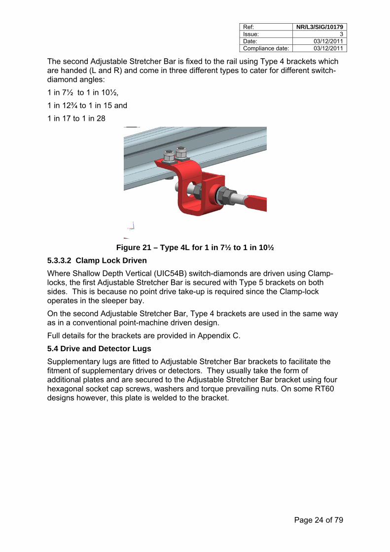
The second Adjustable Stretcher Bar is fixed to the rail using Type 4 brackets which are handed (L and R) and come in three different types to cater for different switch-diamond angles:
1 in 7½ to 1 in 10½,
1 in 12¾ to 1 in 15 and
1 in 17 to 1 in 28
Figure 21 – Type 4L for 1 in 7½ to 1 in 10½
5.3.3.2 Clamp Lock Driven
Where Shallow Depth Vertical (UIC54B) switch-diamonds are driven using Clamp-locks, the first Adjustable Stretcher Bar is secured with Type 5 brackets on both sides. This is because no point drive take-up is required since the Clamp-lock operates in the sleeper bay.
On the second Adjustable Stretcher Bar, Type 4 brackets are used in the same way as in a conventional point-machine driven design.
Full details for the brackets are provided in Appendix C.
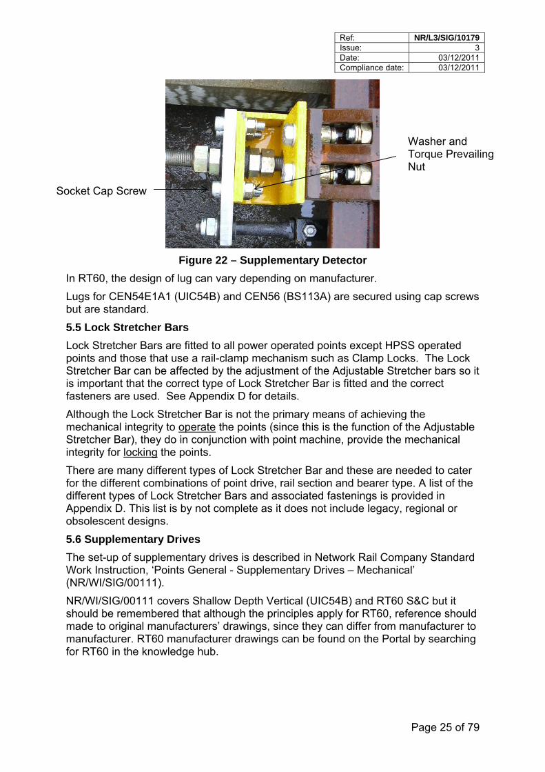
5.4 Drive and Detector Lugs
Supplementary lugs are fitted to Adjustable Stretcher Bar brackets to facilitate the fitment of supplementary drives or detectors. They usually take the form of additional plates and are secured to the Adjustable Stretcher Bar bracket using four hexagonal socket cap screws, washers and torque prevailing nuts. On some RT60 designs however, this plate is welded to the bracket.
Ref: NR/L3/SIG/10179 Issue: 3 Date: 03/12/2011 Compliance date: 03/12/2011
Page 25 of 79
Washer and Torque Prevailing Nut
Socket Cap Screw
Figure 22 – Supplementary Detector
In RT60, the design of lug can vary depending on manufacturer.
Lugs for CEN54E1A1 (UIC54B) and CEN56 (BS113A) are secured using cap screws but are standard.
5.5 Lock Stretcher Bars
Lock Stretcher Bars are fitted to all power operated points except HPSS operated points and those that use a rail-clamp mechanism such as Clamp Locks. The Lock Stretcher Bar can be affected by the adjustment of the Adjustable Stretcher bars so it is important that the correct type of Lock Stretcher Bar is fitted and the correct fasteners are used. See Appendix D for details.
Although the Lock Stretcher Bar is not the primary means of achieving the mechanical integrity to operate the points (since this is the function of the Adjustable Stretcher Bar), they do in conjunction with point machine, provide the mechanical integrity for locking the points.
There are many different types of Lock Stretcher Bar and these are needed to cater for the different combinations of point drive, rail section and bearer type. A list of the different types of Lock Stretcher Bars and associated fastenings is provided in Appendix D. This list is by not complete as it does not include legacy, regional or obsolescent designs.
5.6 Supplementary Drives
The set-up of supplementary drives is described in Network Rail Company Standard Work Instruction, ‘Points General - Supplementary Drives – Mechanical’ (NR/WI/SIG/00111).
NR/WI/SIG/00111 covers Shallow Depth Vertical (UIC54B) and RT60 S&C but it should be remembered that although the principles apply for RT60, reference should made to original manufacturers’ drawings, since they can differ from manufacturer to manufacturer. RT60 manufacturer drawings can be found on the Portal by searching for RT60 in the knowledge hub.
Ref: NR/L3/SIG/10179 Issue: 3 Date: 03/12/2011 Compliance date: 03/12/2011
Page 26 of 79
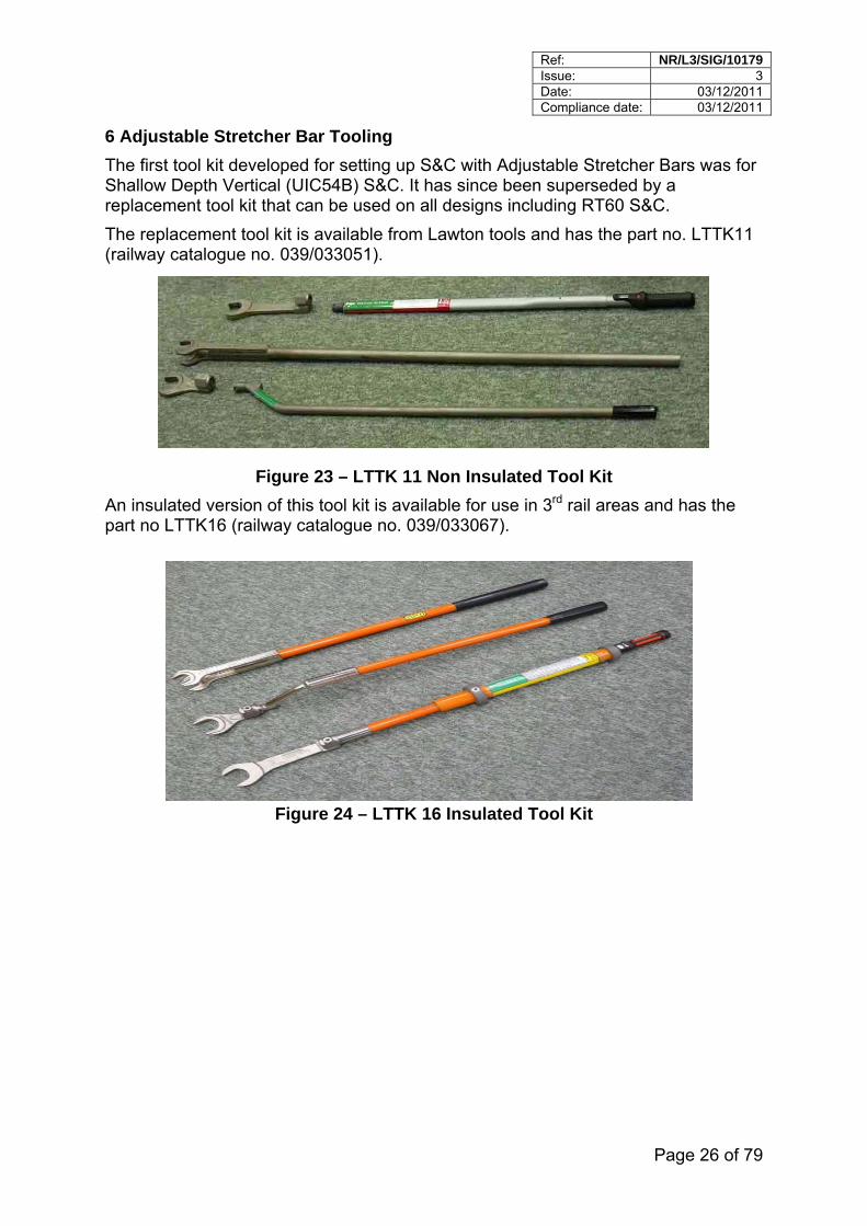
6 Adjustable Stretcher Bar Tooling
The first tool kit developed for setting up S&C with Adjustable Stretcher Bars was for Shallow Depth Vertical (UIC54B) S&C. It has since been superseded by a replacement tool kit that can be used on all designs including RT60 S&C.
The replacement tool kit is available from Lawton tools and has the part no. LTTK11 (railway catalogue no. 039/033051).
Figure 23 – LTTK 11 Non Insulated Tool Kit
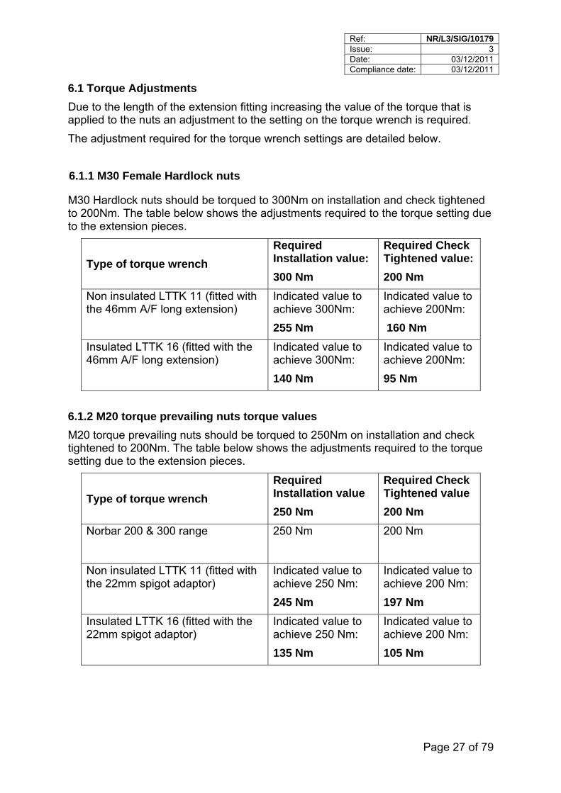
An insulated version of this tool kit is available for use in 3rd rail areas and has the part no LTTK16 (railway catalogue no. 039/033067).
Figure 24 – LTTK 16 Insulated Tool Kit
Ref: NR/L3/SIG/10179 Issue: 3 Date: 03/12/2011 Compliance date: 03/12/2011
Page 27 of 79
6.1 Torque Adjustments
Due to the length of the extension fitting increasing the value of the torque that is applied to the nuts an adjustment to the setting on the torque wrench is required.
The adjustment required for the torque wrench settings are detailed below.
6.1.1 M30 Female Hardlock nuts
M30 Hardlock nuts should be torqued to 300Nm on installation and check tightened to 200Nm. The table below shows the adjustments required to the torque setting due to the extension pieces.
Type of torque wrench
Required Installation value:
300 Nm
Required Check Tightened value:
200 Nm
Non insulated LTTK 11 (fitted with the 46mm A/F long extension)
Indicated value to achieve 300Nm:
255 Nm
Indicated value to achieve 200Nm:
160 Nm
Insulated LTTK 16 (fitted with the 46mm A/F long extension)
Indicated value to achieve 300Nm:
140 Nm
Indicated value to achieve 200Nm:
95 Nm
6.1.2 M20 torque prevailing nuts torque values
M20 torque prevailing nuts should be torqued to 250Nm on installation and check tightened to 200Nm. The table below shows the adjustments required to the torque setting due to the extension pieces.
Type of torque wrench
Required Installation value
250 Nm
Required Check Tightened value
200 Nm
Norbar 200 & 300 range 250 Nm 200 Nm
Non insulated LTTK 11 (fitted with the 22mm spigot adaptor)
Indicated value to achieve 250 Nm:
245 Nm
Indicated value to achieve 200 Nm:
197 Nm
Insulated LTTK 16 (fitted with the 22mm spigot adaptor)
Indicated value to achieve 250 Nm:
135 Nm
Indicated value to achieve 200 Nm:
105 Nm
Ref: NR/L3/SIG/10179 Issue: 3 Date: 03/12/2011 Compliance date: 03/12/2011
Page 28 of 79
6.1.3 M30 Full / half nut assembly values (half nut)
M30 full/half nuts should be torqued to 300Nm on installation and check tightened to 200Nm. The table below shows the adjustments required to the torque setting due to the extension pieces.
Type of torque wrench
Required Installation value
300 Nm
Required Check Tightened value
200 Nm
Non insulated LTTK 11 (fitted with the 46mm A/F long extension)
Indicated value to achieve 300 Nm:
255 Nm
Indicated value to achieve 200 Nm:
160 Nm
Insulated LTTK 16 (fitted with the 46mm A/F long extension)
Indicated value to achieve 300 Nm:
140 Nm
Indicated value to achieve 200 Nm:
95 Nm
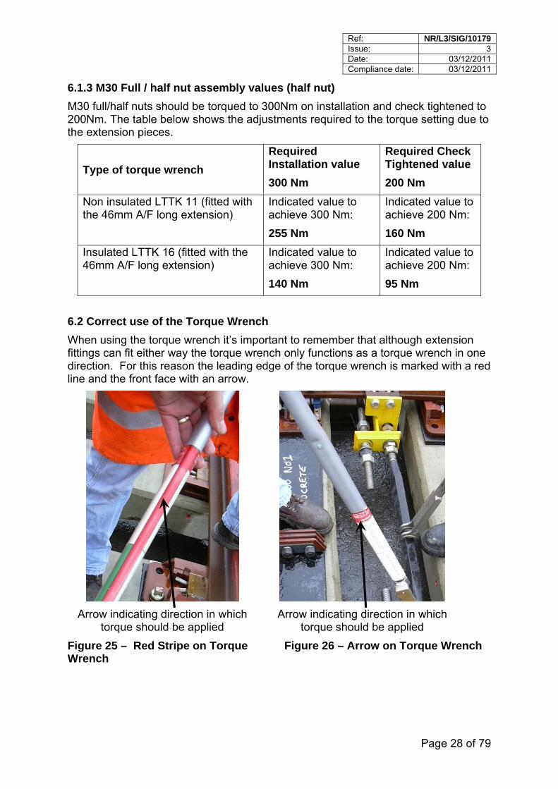
6.2 Correct use of the Torque Wrench
When using the torque wrench it’s important to remember that although extension fittings can fit either way the torque wrench only functions as a torque wrench in one direction. For this reason the leading edge of the torque wrench is marked with a red line and the front face with an arrow.
Arrow indicating direction in which torque should be applied
Arrow indicating direction in which torque should be applied
Figure 25 – Red Stripe on Torque Wrench
Figure 26 – Arrow on Torque Wrench
Ref: NR/L3/SIG/10179 Issue: 3 Date: 03/12/2011 Compliance date: 03/12/2011
Page 29 of 79
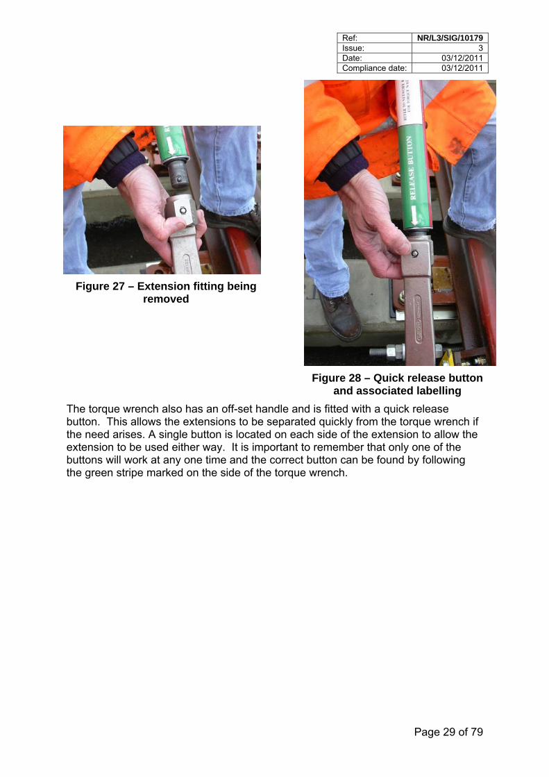
Figure 27 – Extension fitting being removed
Figure 28 – Quick release button and associated labelling
The torque wrench also has an off-set handle and is fitted with a quick release button. This allows the extensions to be separated quickly from the torque wrench if the need arises. A single button is located on each side of the extension to allow the extension to be used either way. It is important to remember that only one of the buttons will work at any one time and the correct button can be found by following the green stripe marked on the side of the torque wrench.
Ref: NR/L3/SIG/10179 Issue: 3 Date: 03/12/2011 Compliance date: 03/12/2011
Page 30 of 79
7 Installation and Set Up
There are many different scenarios that can give rise to the installation or part installation of Adjustable Stretcher Bar assemblies. For simplicity the method described in this standard assumes that the layout being fitted does not have a point-drive and therefore the points have to be barred-over to alter the position of the switches, e.g. being assembled in a yard.
The procedure for changing individual sub-components such as brackets and bushes is not specifically described but the same principles should be applied.
7.1 Assembly Sequence
The assembly sequence for S&C using Adjustable Stretcher Bars is summarised below along with the section numbers that contains the detail, shown in brackets.
Pre-Check (See 7.2)
Pre-Building Adjustable Stretcher Bar Assemblies (See 7.3)
Prepare the layout for fitting (See 7.4)
Calculation of Free Wheel Clearance (See 7.5)
Switch Openings – Nominal Free Wheel Clearance (See 7.6)
Fit the Rear Adjustable Stretcher Bar (See 7.7)
Type 1 Brackets (See 7.7.1)
Securing Hard Lock Nuts (see 7.7.2)
Type 2 Brackets (See 7.7.3)
Fit the Lock Stretcher Bar (See 7.8)
Fit the 1st Adjustable Stretcher Bar (See 7.9)
Fit the Intermediate Stretcher Bars (See 7.10)
Set up and check (See 7.11)
Fit and set up Supplementary Drive (See 7.12)
Post installation Gauge Checks (See 7.13)
Ref: NR/L3/SIG/10179 Issue: 3 Date: 03/12/2011 Compliance date: 03/12/2011
Page 31 of 79
7.2 Pre-Check
Carry out the following pre-checks on each of the components listed below.
Adjustable Stretcher Bars Check the threads are in good condition.
Hardlock nuts Check that the M30 Hardlock nuts run freely on the threads of the Adjustable Stretcher Bars (this is particularly important if refurbished Adjustable Stretcher Bars are used since damage can occur to the threads).
Brackets Check the brackets are good condition and the correct number and type have been supplied.
Bracket fasteners Check the correct type have been supplied.
Bushes Check they are in good condition and fit easily into the brackets.
7.3 Pre-Building Adjustable Stretcher Bar Assemblies
The following describes how to build-up Adjustable Stretcher Bar assemblies. This procedure can be followed for all assemblies except the 1st Adjustable Stretcher Bar (which has an integral kicking strap) for which section 7.9 should be followed.
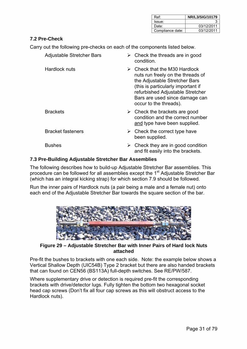
Run the inner pairs of Hardlock nuts (a pair being a male and a female nut) onto each end of the Adjustable Stretcher Bar towards the square section of the bar.
Figure 29 – Adjustable Stretcher Bar with Inner Pairs of Hard lock Nuts attached
Pre-fit the bushes to brackets with one each side. Note: the example below shows a Vertical Shallow Depth (UIC54B) Type 2 bracket but there are also handed brackets that can found on CEN56 (BS113A) full-depth switches. See RE/PW/587.
Where supplementary drive or detection is required pre-fit the corresponding brackets with drive/detector lugs. Fully tighten the bottom two hexagonal socket head cap screws (Don’t fix all four cap screws as this will obstruct access to the Hardlock nuts).
Ref: NR/L3/SIG/10179 Issue: 3 Date: 03/12/2011 Compliance date: 03/12/2011
Page 32 of 79
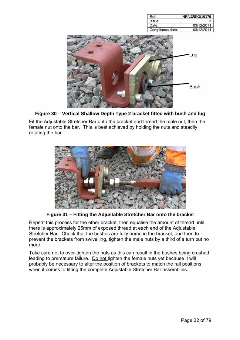
Bush
Lug
Figure 30 – Vertical Shallow Depth Type 2 bracket fitted with bush and lug
Fit the Adjustable Stretcher Bar onto the bracket and thread the male nut, then the female nut onto the bar. This is best achieved by holding the nuts and steadily rotating the bar
Figure 31 – Fitting the Adjustable Stretcher Bar onto the bracket
Repeat this process for the other bracket, then equalise the amount of thread until there is approximately 25mm of exposed thread at each end of the Adjustable Stretcher Bar. Check that the bushes are fully home in the bracket, and then to prevent the brackets from swivelling, tighten the male nuts by a third of a turn but no more.
Take care not to over-tighten the nuts as this can result in the bushes being crushed leading to premature failure. Do not tighten the female nuts yet because it will probably be necessary to alter the position of brackets to match the rail positions when it comes to fitting the complete Adjustable Stretcher Bar assemblies.
Ref: NR/L3/SIG/10179 Issue: 3 Date: 03/12/2011 Compliance date: 03/12/2011
Page 33 of 79
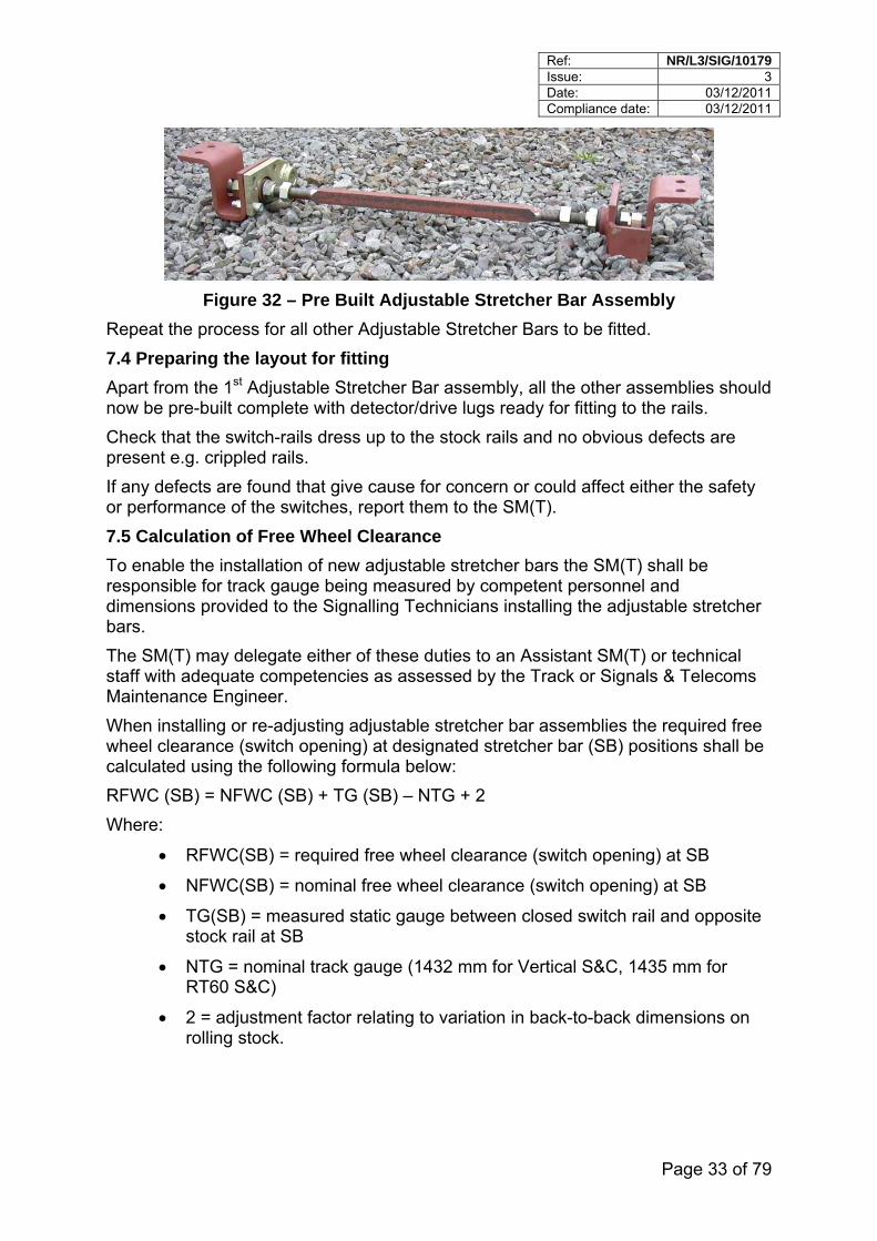
Figure 32 – Pre Built Adjustable Stretcher Bar Assembly
Repeat the process for all other Adjustable Stretcher Bars to be fitted.
7.4 Preparing the layout for fitting
Apart from the 1st Adjustable Stretcher Bar assembly, all the other assemblies should now be pre-built complete with detector/drive lugs ready for fitting to the rails.
Check that the switch-rails dress up to the stock rails and no obvious defects are present e.g. crippled rails.
If any defects are found that give cause for concern or could affect either the safety or performance of the switches, report them to the SM(T).
7.5 Calculation of Free Wheel Clearance
To enable the installation of new adjustable stretcher bars the SM(T) shall be responsible for track gauge being measured by competent personnel and dimensions provided to the Signalling Technicians installing the adjustable stretcher bars.
The SM(T) may delegate either of these duties to an Assistant SM(T) or technical staff with adequate competencies as assessed by the Track or Signals & Telecoms Maintenance Engineer.
When installing or re-adjusting adjustable stretcher bar assemblies the required free wheel clearance (switch opening) at designated stretcher bar (SB) positions shall be calculated using the following formula below:
RFWC (SB) = NFWC (SB) + TG (SB) – NTG + 2
Where:
RFWC(SB) = required free wheel clearance (switch opening) at SB
NFWC(SB) = nominal free wheel clearance (switch opening) at SB
TG(SB) = measured static gauge between closed switch rail and opposite stock rail at SB
NTG = nominal track gauge (1432 mm for Vertical S&C, 1435 mm for RT60 S&C)
2 = adjustment factor relating to variation in back-to-back dimensions on rolling stock.

Ref: NR/L3/SIG/10179 Issue: 3 Date: 03/12/2011 Compliance date: 03/12/2011
Page 34 of 79
Fin n of stretcher bar length once open switch rail has been set to
rear stretcher bar (or rear es and longer).
actions or mitigations and escalate to the S&TME/TME and IME as
are for a track gauge of 1432 mm for Vertical S&C, or 1435
ine operation unless otherwise shown.
the
ils of which
d be used are provided in Appendix C of this standard.
Note:
IC54B) S&C switches all rear stretchers are
Notes:
1. Closed switch rail to be in the same position for:
Measurement of track gauge for use in this formula; and
al determinatioRFWC (SB).
2. The 2 mm adjustment factor shall only be applied to thetwo stretcher bars on E switch
3. All dimensions in millimetres
Note this formula is reproduced on TEF3074.
Where track gauge is found to be out of tolerance, the SM(T) and SM(S) shall plan the necessaryappropriate.
7.6 Switch Openings – Nominal Free Wheel Clearance
The tables in Appendix H shall be used when setting up adjustable stretcher bar assemblies. The valuesmm for inclined S&C.
The values in Appendix H are for point mach
7.7 Fit the Rear Adjustable Stretcher Bar
Bar the points over one way and on the closed side set the switch openings toRequired Free Wheel Clearance (RFWC) calculated using the formula in 7.5.
Fit the rear Stretcher Bar assembly to the rails using the appropriate bracket on oneside then bar the points over to the opposite position and repeat. Detabrackets shoul
On Shallow Depth Vertical (Ufixed with Type 2 brackets.
On CEN56 (BS113A) full-depth S&C brackets are fixed to the rail but are
he
brackets from different manufacturers may not be interchangeable.
unique to CEN56 (BS113A) full depth;
On RT60 designs all Adjustable Stretcher Bar assemblies, including trear Adjustable Stretcher Bars are secured to the rail with Type 1 brackets however
Ref: NR/L3/SIG/10179 Issue: 3 Date: 03/12/2011 Compliance date: 03/12/2011
Page 35 of 79
7.7.1 Type 1 brackets
Before attempting assembly, check that any rail branding has been removed from the web where the spacer blocks are to be fitted. If not, arrange with the SM(T) to have the branding ground off.
With the switches fully closed on one side, fit the Adjustable Stretcher Bar assembly by carrying out the following procedure:
Fit and secure the spacer blocks to the rail;
Fit the Adjustable Stretcher Bar assembly to the spacer blocks. If it is not a good fit, alter the position of the Adjustable Stretcher Bar by winding in or out the male Hardlock nuts to suit.
Insert the M20 bolts from the back of the switch, attach the spacer blocks and bracket, secure with an M20 Torque Prevailing nut, and then tighten to a torque of 250Nm.
Note: previously it was permissible to fit any type of self-locking nut, this is now restricted to approved types of torque prevailing nuts.
Operate the switches to opposite position and repeat the above process.
Because the male nuts were tightened to enable the Adjustable Stretcher Bar assemblies to be lifted in place without the brackets swivelling, undo each of the male nuts sufficiently to release the compression on the bushes. Then, re-tighten each of the male Hardlock nuts by a third of a turn to re-compress the bushes.
7.7.2 Securing Hard Lock Nuts
With the Adjustable Stretcher Bar assembly attached to the rails, follow this method to secure the Hard Lock nuts.
To prevent the Adjustable Stretcher Bar rotating while tightening the Hardlock nuts, hold the Adjustable Stretcher Bar at the square section of the Adjustable Stretcher Bar using the twin-head open-ended spanner. Hold the male nut using the off-set handle fitted with the 46mm A/F short extension. With male nut held securely, fit the torque wrench with the long extension to the female nut and tighten to 300Nm.
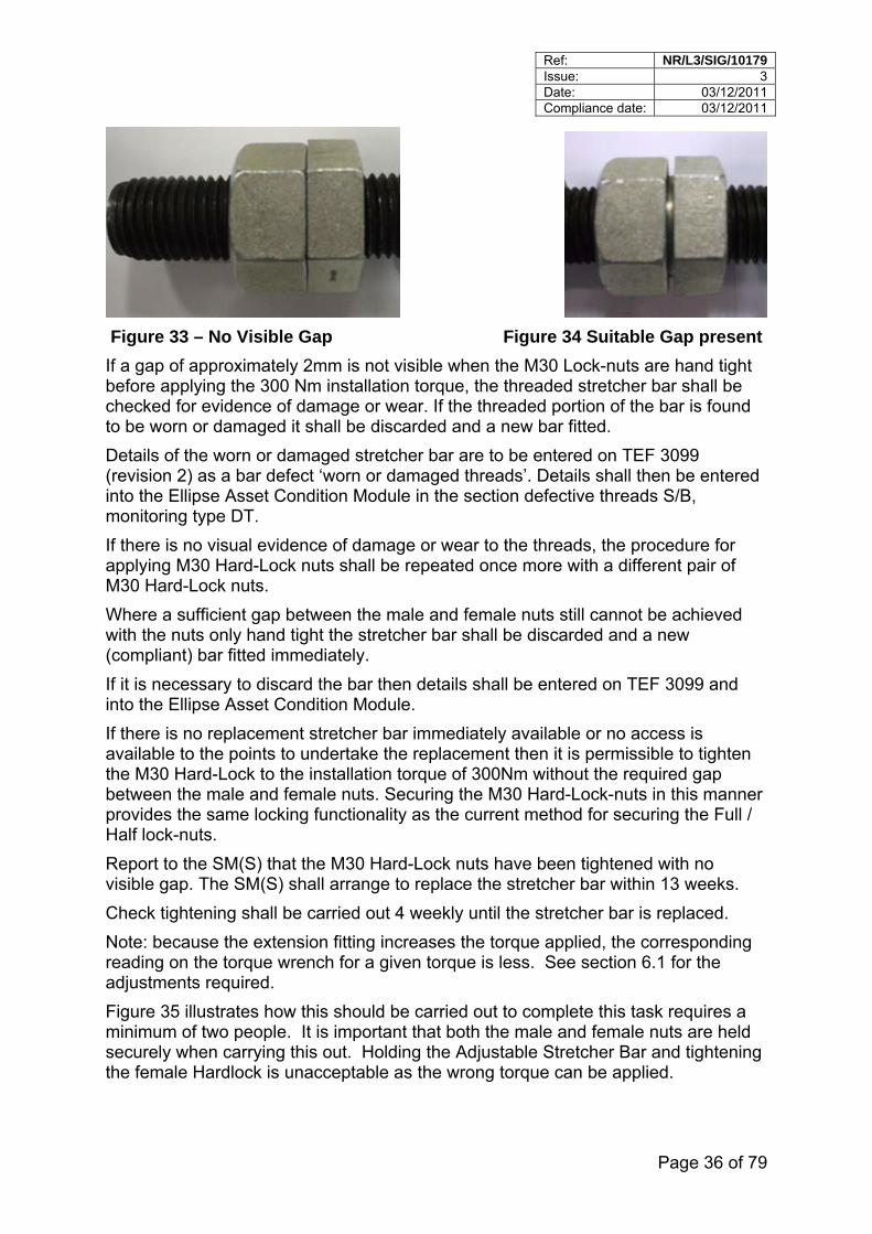
Before tightening to the installation torque of 300 Nm, the interlocking cones of the male and female nuts are to be initially engaged to hand tightness -there shall be a visible gap (approximately 2mm) between the nuts. A 1.5mm gauge can be used to check the size of the gap.
It is important that there is a gap of approximately 2mm present between the male and female nuts after they have been tightened by hand, before the installation torque value is applied. If the gap is not present, the lock nut may not provide its full intended locking effect.
Ref: NR/L3/SIG/10179 Issue: 3 Date: 03/12/2011 Compliance date: 03/12/2011
Page 36 of 79
Figure 33 – No Visible Gap Figure 34 Suitable Gap present
If a gap of approximately 2mm is not visible when the M30 Lock-nuts are hand tight before applying the 300 Nm installation torque, the threaded stretcher bar shall be checked for evidence of damage or wear. If the threaded portion of the bar is found to be worn or damaged it shall be discarded and a new bar fitted.
Details of the worn or damaged stretcher bar are to be entered on TEF 3099 (revision 2) as a bar defect ‘worn or damaged threads’. Details shall then be entered into the Ellipse Asset Condition Module in the section defective threads S/B, monitoring type DT.
If there is no visual evidence of damage or wear to the threads, the procedure for applying M30 Hard-Lock nuts shall be repeated once more with a different pair of M30 Hard-Lock nuts.
Where a sufficient gap between the male and female nuts still cannot be achieved with the nuts only hand tight the stretcher bar shall be discarded and a new (compliant) bar fitted immediately.
If it is necessary to discard the bar then details shall be entered on TEF 3099 and into the Ellipse Asset Condition Module.
If there is no replacement stretcher bar immediately available or no access is available to the points to undertake the replacement then it is permissible to tighten the M30 Hard-Lock to the installation torque of 300Nm without the required gap between the male and female nuts. Securing the M30 Hard-Lock-nuts in this manner provides the same locking functionality as the current method for securing the Full / Half lock-nuts.
Report to the SM(S) that the M30 Hard-Lock nuts have been tightened with no visible gap. The SM(S) shall arrange to replace the stretcher bar within 13 weeks.
Check tightening shall be carried out 4 weekly until the stretcher bar is replaced.
Note: because the extension fitting increases the torque applied, the corresponding reading on the torque wrench for a given torque is less. See section 6.1 for the adjustments required.
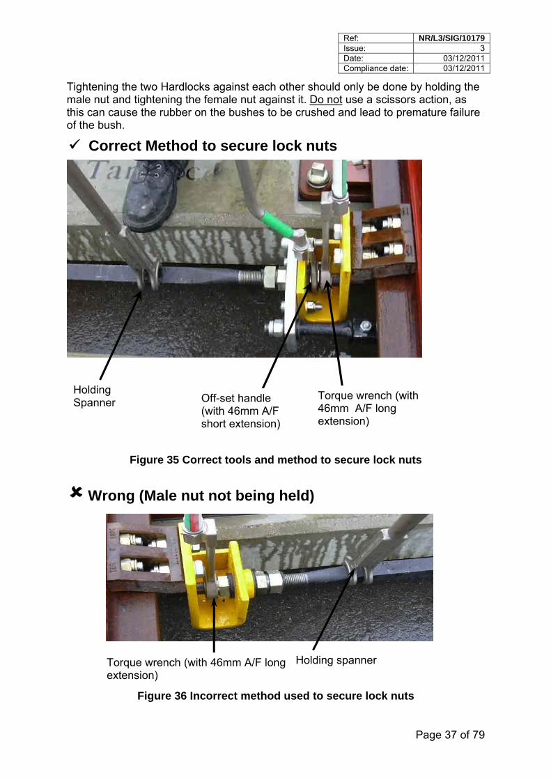
Figure 35 illustrates how this should be carried out to complete this task requires a minimum of two people. It is important that both the male and female nuts are held securely when carrying this out. Holding the Adjustable Stretcher Bar and tightening the female Hardlock is unacceptable as the wrong torque can be applied.
Ref: NR/L3/SIG/10179 Issue: 3 Date: 03/12/2011 Compliance date: 03/12/2011
Page 37 of 79
Tightening the two Hardlocks against each other should only be done by holding the male nut and tightening the female nut against it. Do not use a scissors action, as this can cause the rubber on the bushes to be crushed and lead to premature failure of the bush.
Correct Method to secure lock nuts
Torque wrench (with 46mm A/F long extension)
Off-set handle (with 46mm A/F short extension)
Holding Spanner
Figure 35 Correct tools and method to secure lock nuts
Wrong (Male nut not being held)
Torque wrench (with 46mm A/F long extension)
Holding spanner
Figure 36 Incorrect method used to secure lock nuts
Ref: NR/L3/SIG/10179 Issue: 3 Date: 03/12/2011 Compliance date: 03/12/2011
Page 38 of 79
Once fitted, check that the Adjustable Stretcher Bar is reasonably symmetrical and has a minimum of two threads exposed at each end.
If a supplementary drive/detector lug has been fitted, fit the remaining top two cap screws.
7.7.3 Type 2 brackets
Fit the Adjustable Stretcher Bar assembly to the rails. If the bracket fixing holes on Adjustable Stretcher Bar brackets are not in line with the fixing holes in the rail, alter the position of the brackets by winding the male Hardlocks in or out to suit.
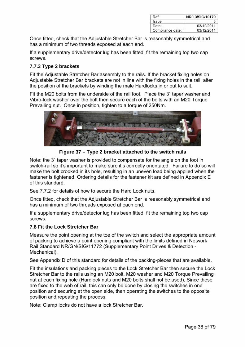
Fit the M20 bolts from the underside of the rail foot. Place the 3˚ taper washer and Vibro-lock washer over the bolt then secure each of the bolts with an M20 Torque Prevailing nut. Once in position, tighten to a torque of 250Nm.
Figure 37 – Type 2 bracket attached to the switch rails
Note: the 3˚ taper washer is provided to compensate for the angle on the foot in switch-rail so it’s important to make sure it’s correctly orientated. Failure to do so will make the bolt crooked in its hole, resulting in an uneven load being applied when the fastener is tightened. Ordering details for the fastener kit are defined in Appendix E of this standard.
See 7.7.2 for details of how to secure the Hard Lock nuts.
Once fitted, check that the Adjustable Stretcher Bar is reasonably symmetrical and has a minimum of two threads exposed at each end.
If a supplementary drive/detector lug has been fitted, fit the remaining top two cap screws.
7.8 Fit the Lock Stretcher Bar
Measure the point opening at the toe of the switch and select the appropriate amount of packing to achieve a point opening compliant with the limits defined in Network Rail Standard NR/GN/SIG/11772 (Supplementary Point Drives & Detection - Mechanical).
See Appendix D of this standard for details of the packing-pieces that are available.
Fit the insulations and packing pieces to the Lock Stretcher Bar then secure the Lock Stretcher Bar to the rails using an M20 bolt, M20 washer and M20 Torque Prevailing nut at each fixing hole (Hardlock nuts and M20 bolts shall not be used). Since these are fixed to the web of rail, this can only be done by closing the switches in one position and securing at the open side, then operating the switches to the opposite position and repeating the process.
Note: Clamp locks do not have a lock Stretcher Bar.
Ref: NR/L3/SIG/10179 Issue: 3 Date: 03/12/2011 Compliance date: 03/12/2011
Page 39 of 79
7.9 Fit the 1st Adjustable Stretcher Bar Assembly
The method used to fix the 1st Adjustable Stretcher Bar assembly will depend on the degree of accessibility that exists in the sleeper bay. Where the sleeper bay is well clear of ballast it should be possible to pre-build the Adjustable Stretcher Bar Assembly complete with its brackets, and fix it to the rails. Where this is not possible, e.g. replacement under maintenance, ballast will need to be cleared at one end of the sleeper bay (to enable the kicking strap to pass under the rail) also in the sleeper bay itself, sufficient to be able to manoeuvre the assembly into position and fix it to the rails. The following describes the fitting method where the sleeper bay is only partially clear.
Bar the points over midway so that access can be gained to the outside of each switch-rail and place blocks in the openings.
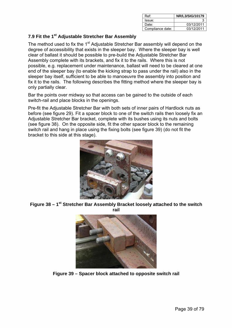
Pre-fit the Adjustable Stretcher Bar with both sets of inner pairs of Hardlock nuts as before (see figure 29). Fit a spacer block to one of the switch rails then loosely fix an Adjustable Stretcher Bar bracket, complete with its bushes using its nuts and bolts (see figure 38). On the opposite side, fit the other spacer block to the remaining switch rail and hang in place using the fixing bolts (see figure 39) (do not fit the bracket to this side at this stage).
Figure 38 – 1st Stretcher Bar Assembly Bracket loosely attached to the switch rail
Figure 39 – Spacer block attached to opposite switch rail
Ref: NR/L3/SIG/10179 Issue: 3 Date: 03/12/2011 Compliance date: 03/12/2011
Page 40 of 79
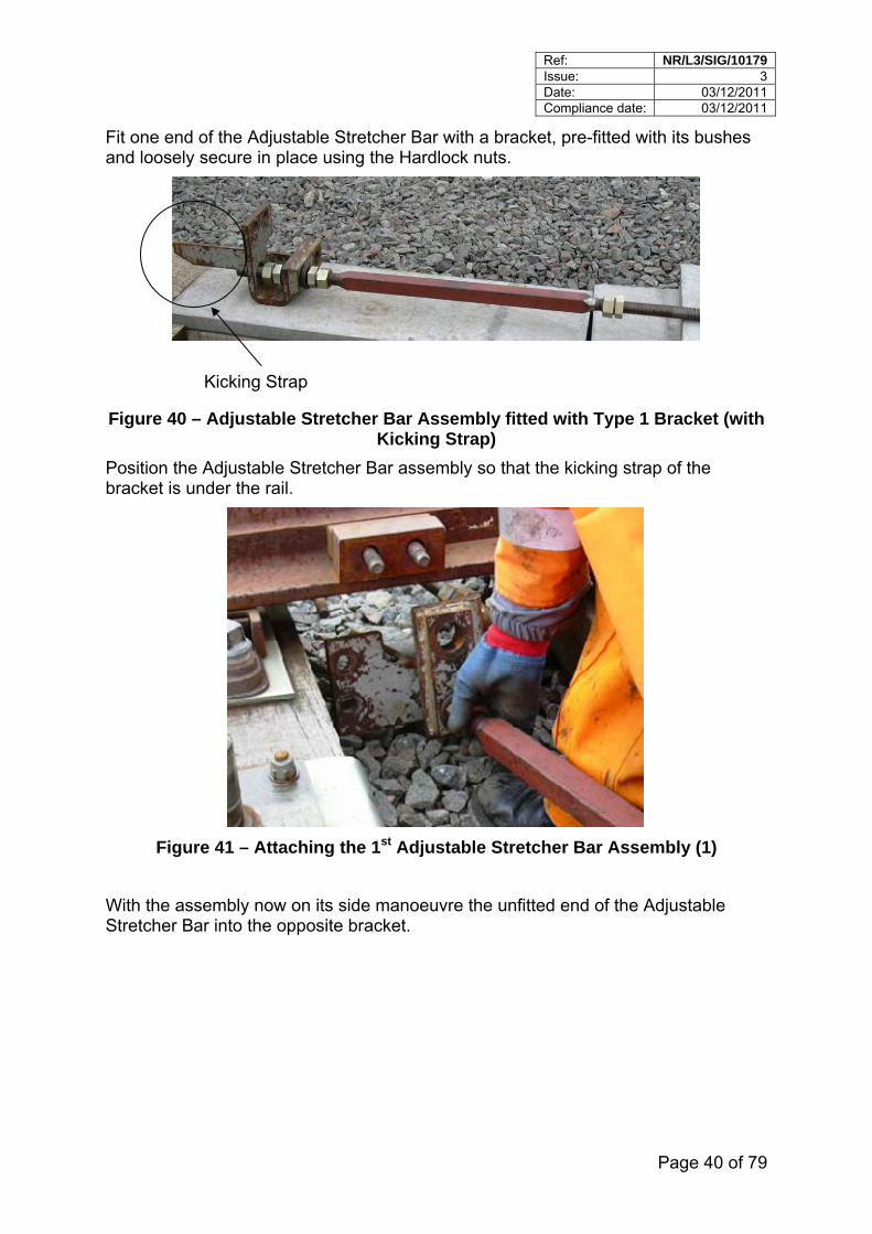
Fit one end of the Adjustable Stretcher Bar with a bracket, pre-fitted with its bushes and loosely secure in place using the Hardlock nuts.
Kicking Strap
Figure 40 – Adjustable Stretcher Bar Assembly fitted with Type 1 Bracket (with Kicking Strap)
Position the Adjustable Stretcher Bar assembly so that the kicking strap of the bracket is under the rail.
Figure 41 – Attaching the 1st Adjustable Stretcher Bar Assembly (1)
With the assembly now on its side manoeuvre the unfitted end of the Adjustable Stretcher Bar into the opposite bracket.
Ref: NR/L3/SIG/10179 Issue: 3 Date: 03/12/2011 Compliance date: 03/12/2011
Page 41 of 79
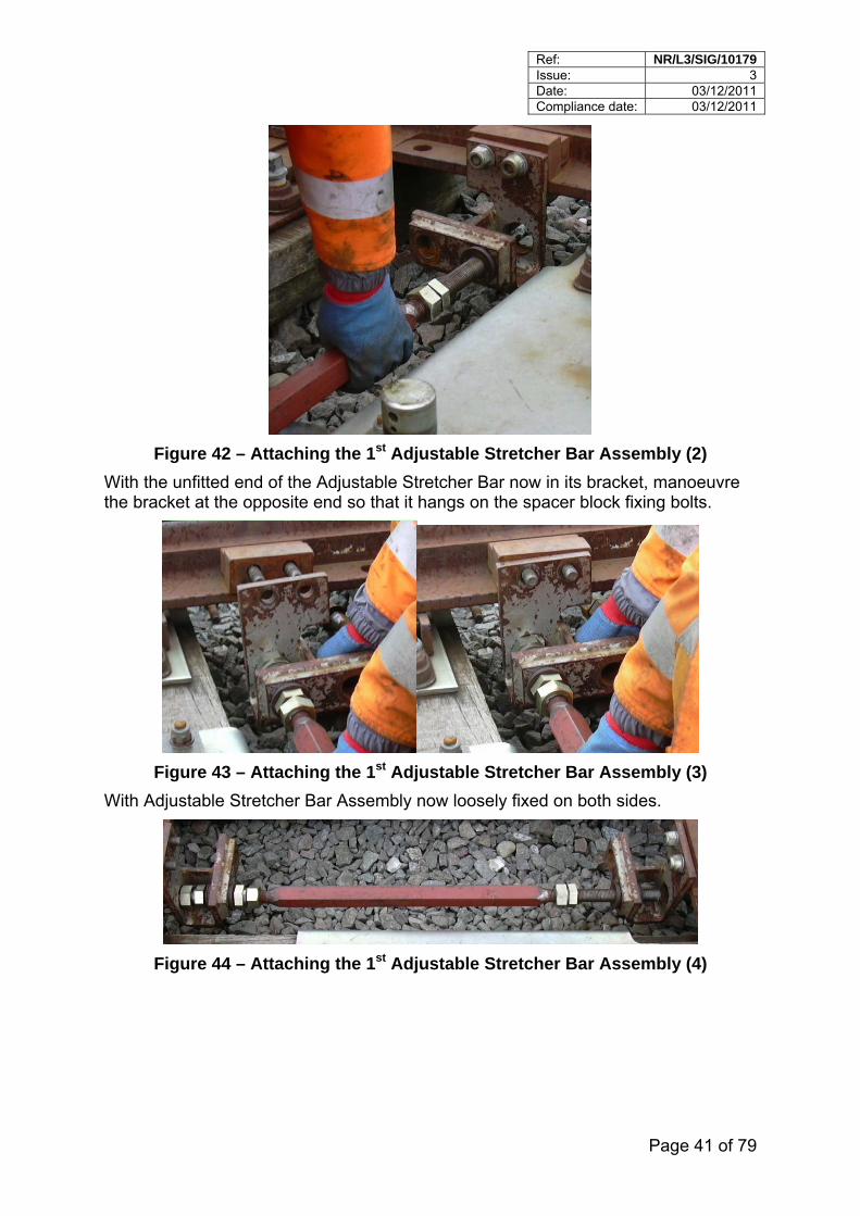
Figure 42 – Attaching the 1st Adjustable Stretcher Bar Assembly (2)
With the unfitted end of the Adjustable Stretcher Bar now in its bracket, manoeuvre the bracket at the opposite end so that it hangs on the spacer block fixing bolts.
Figure 43 – Attaching the 1st Adjustable Stretcher Bar Assembly (3)
With Adjustable Stretcher Bar Assembly now loosely fixed on both sides.
Figure 44 – Attaching the 1st Adjustable Stretcher Bar Assembly (4)
Ref: NR/L3/SIG/10179 Issue: 3 Date: 03/12/2011 Compliance date: 03/12/2011
Page 42 of 79
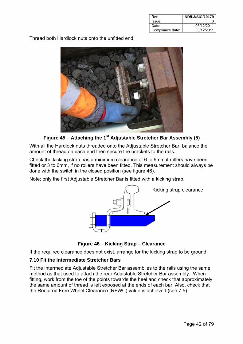
Thread both Hardlock nuts onto the unfitted end.
Figure 45 – Attaching the 1st Adjustable Stretcher Bar Assembly (5)
With all the Hardlock nuts threaded onto the Adjustable Stretcher Bar, balance the amount of thread on each end then secure the brackets to the rails.
Check the kicking strap has a minimum clearance of 6 to 9mm if rollers have been fitted or 3 to 6mm, if no rollers have been fitted. This measurement should always be done with the switch in the closed position (see figure 46).
Note: only the first Adjustable Stretcher Bar is fitted with a kicking strap.
Kicking strap clearance
Figure 46 – Kicking Strap – Clearance
If the required clearance does not exist, arrange for the kicking strap to be ground.
7.10 Fit the Intermediate Stretcher Bars
Fit the intermediate Adjustable Stretcher Bar assemblies to the rails using the same method as that used to attach the rear Adjustable Stretcher Bar assembly. When fitting, work from the toe of the points towards the heel and check that approximately the same amount of thread is left exposed at the ends of each bar. Also, check that the Required Free Wheel Clearance (RFWC) value is achieved (see 7.5).
Ref: NR/L3/SIG/10179 Issue: 3 Date: 03/12/2011 Compliance date: 03/12/2011
Page 43 of 79
7.11 Set up check
Where a Lock Stretcher Bar is fitted, move the switches from side-to-side and check that the switch-rail dresses up to the stock rail between the Lock Stretcher Bar and the 1st Adjustable Stretcher Bar. Repeat for the other side.
(Not applicable on Clamp-locks).
Observe for flexing of the Adjustable Stretcher Bar brackets and the Lock Stretcher Bar. Where a degree of excessive flexing is observed, remove by adjusting the Adjustable Stretcher Bar.
Using the S&C maintenance gauge, check that the Required Free Wheel Clearance (RFWC) has been achieved, if not, adjust the stretcher bars as necessary.
Re-check that the Adjustable Stretcher Bars are reasonably symmetrical and a minimum 4 threads (2 threads if Hardlock nuts are used) are exposed beyond the end of each locking nut.
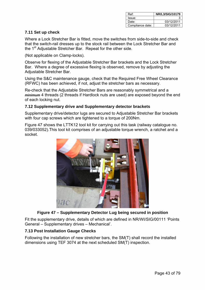
7.12 Supplementary drive and Supplementary detector brackets
Supplementary drive/detector lugs are secured to Adjustable Stretcher Bar brackets with four cap screws which are tightened to a torque of 200Nm.
Figure 47 shows the LTTK12 tool kit for carrying out this task (railway catalogue no. 039/033052).This tool kit comprises of an adjustable torque wrench, a ratchet and a socket.
Figure 47 – Supplementary Detector Lug being secured in position
Fit the supplementary drive, details of which are defined in NR/WI/SIG/00111 ‘Points General – Supplementary drives – Mechanical’.
7.13 Post Installation Gauge Checks
Following the installation of new stretcher bars, the SM(T) shall record the installed dimensions using TEF 3074 at the next scheduled SM(T) inspection.
Ref: NR/L3/SIG/10179 Issue: 3 Date: 03/12/2011 Compliance date: 03/12/2011
Page 44 of 79
8 Maintenance
8.1 General
The adjustable stretcher bar assembly (including the stretcher bar complete with bushes, lock nuts and brackets) shall be regarded as a single unit, if any defects are found with the bar, bushes or brackets the whole assembly shall be replaced. Where individual nuts and bolts require replacement, the nut and bolt may be replaced alone.
Any damaged or poorly maintained components e.g. supplementary drive can result in undesirable stresses in the Adjustable Stretcher Bar Assemblies and Lock Stretcher Bars. These stresses can apply when the points are locked and during movement of the switch blades and can lead to premature failure of Stretcher Bar components, e.g. bushes. Do not rely on Adjustable Stretcher Bars rattling or vibrating to test the tightness of components. Loose nuts can be established by visual inspection, there maybe witness marks present in the grease / deposits around the area where stretcher bar bracket is connected to the switch rail.
See Appendix I for the minimum actions for adjustable stretcher bar defects.
8.2 Examination of Components
The examination of adjustable stretcher bar assembly components is carried out in accordance with NR/SMS/PF01.
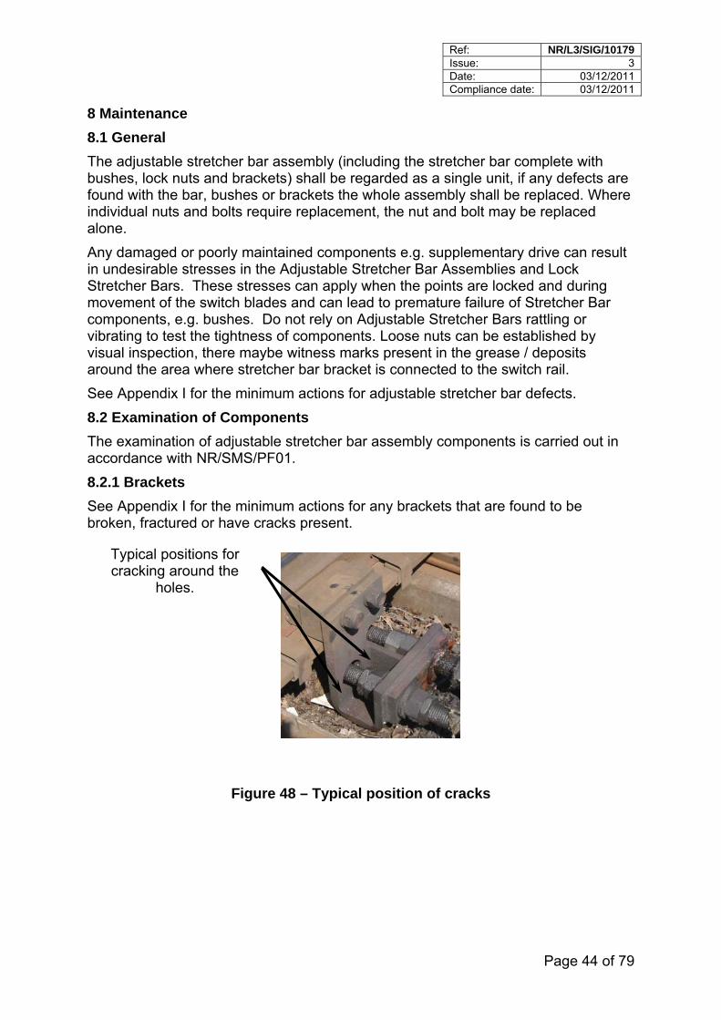
8.2.1 Brackets
See Appendix I for the minimum actions for any brackets that are found to be broken, fractured or have cracks present.
Typical positions for cracking around the
holes.
Figure 48 – Typical position of cracks
Ref: NR/L3/SIG/10179 Issue: 3 Date: 03/12/2011 Compliance date: 03/12/2011
Page 45 of 79
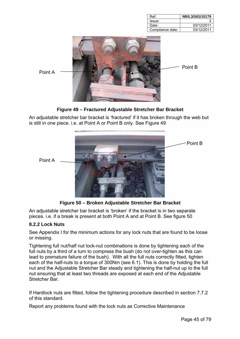
Point B Point A
Figure 49 – Fractured Adjustable Stretcher Bar Bracket
An adjustable stretcher bar bracket is ‘fractured’ if it has broken through the web but is still in one piece. i.e. at Point A or Point B only. See Figure 49
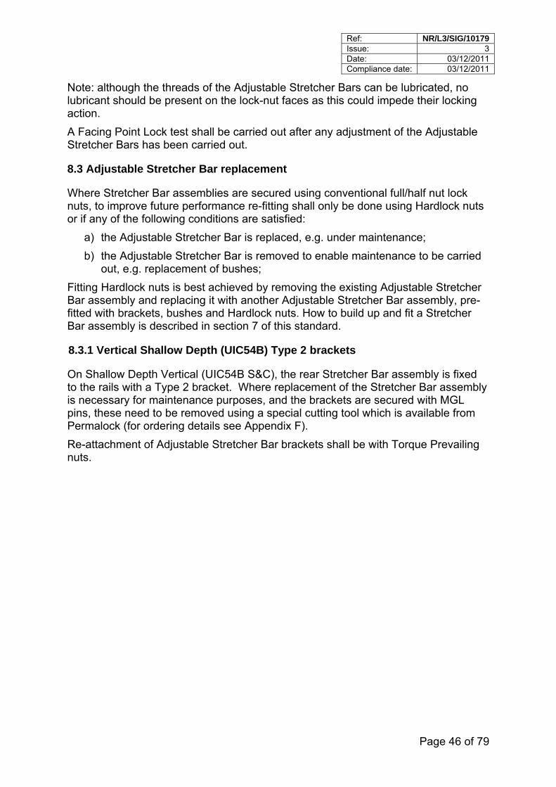
Point B
Point A
Figure 50 – Broken Adjustable Stretcher Bar Bracket
An adjustable stretcher bar bracket is ‘broken’ if the bracket is in two separate pieces. i.e. if a break is present at both Point A and at Point B. See figure 50
8.2.2 Lock Nuts
See Appendix I for the minimum actions for any lock nuts that are found to be loose or missing.
Tightening full nut/half nut lock-nut combinations is done by tightening each of the full nuts by a third of a turn to compress the bush (do not over-tighten as this can lead to premature failure of the bush). With all the full nuts correctly fitted, tighten each of the half-nuts to a torque of 300Nm (see 6.1). This is done by holding the full nut and the Adjustable Stretcher Bar steady and tightening the half-nut up to the full nut ensuring that at least two threads are exposed at each end of the Adjustable Stretcher Bar.
If Hardlock nuts are fitted, follow the tightening procedure described in section 7.7.2 of this standard.
Report any problems found with the lock nuts as Corrective Maintenance
Ref: NR/L3/SIG/10179 Issue: 3 Date: 03/12/2011 Compliance date: 03/12/2011
Page 46 of 79
Note: although the threads of the Adjustable Stretcher Bars can be lubricated, no lubricant should be present on the lock-nut faces as this could impede their locking action.
A Facing Point Lock test shall be carried out after any adjustment of the Adjustable Stretcher Bars has been carried out.
8.3 Adjustable Stretcher Bar replacement
Where Stretcher Bar assemblies are secured using conventional full/half nut lock nuts, to improve future performance re-fitting shall only be done using Hardlock nuts or if any of the following conditions are satisfied:
a) the Adjustable Stretcher Bar is replaced, e.g. under maintenance;
b) the Adjustable Stretcher Bar is removed to enable maintenance to be carried out, e.g. replacement of bushes;
Fitting Hardlock nuts is best achieved by removing the existing Adjustable Stretcher Bar assembly and replacing it with another Adjustable Stretcher Bar assembly, pre-fitted with brackets, bushes and Hardlock nuts. How to build up and fit a Stretcher Bar assembly is described in section 7 of this standard.
8.3.1 Vertical Shallow Depth (UIC54B) Type 2 brackets
On Shallow Depth Vertical (UIC54B S&C), the rear Stretcher Bar assembly is fixed to the rails with a Type 2 bracket. Where replacement of the Stretcher Bar assembly is necessary for maintenance purposes, and the brackets are secured with MGL pins, these need to be removed using a special cutting tool which is available from Permalock (for ordering details see Appendix F).
Re-attachment of Adjustable Stretcher Bar brackets shall be with Torque Prevailing nuts.

Ref: NR/L3/SIG/10179 Issue: 3 Date: 03/12/2011 Compliance date: 03/12/2011
Page 47 of 79
8.4 Supplementary Drive/Detector lugs
Where Supplementary Drive/Detector Lugs are fitted this can restrict access to lock-nuts making tightness checking difficult. To overcome this, it is permissible to temporarily remove the top two set screws and have the points used by traffic providing both bottom cap screws are in-place, secure and tight.
Accessibility to the bottom cap screw nearest the strengthening web can only be done by first of all removing the cap screw above it. Once this is done it is possible to check the tightness of both bottom cap screws.
With both top screws removed check the tightness of the Hardlock nuts.
Bracket
top two set screws
strengthening web
Bottom two set screws
Figure 51 – Supplementary Drive Lug
8.5 Recording of stretcher bar defects
All corrective actions or defects found on adjustable stretcher bars shall be recorded on TEF3099 and input into the ELLIPSE Asset Condition Module for adjustable stretcher bars.
8.6 Minimum Actions for Adjustable Stretcher Bar Assembly Defects
See Appendix I for minimum actions for Adjustable Stretcher Bar assembly defects

Ref: NR/L3/SIG/10179 Issue: 3 Date: 03/12/2011 Compliance date: 03/12/2011
Page 48 of 79
9 Problem Solving
9.1 Track Condition
Where the condition of the track is poor giving rise to high levels of vibration this can lead to vertical stresses being introduced. Voiding at switch toes should be no greater than 7mm when within 3 m of the toes of the switch. Where voids exceed this value it shall be reported to the SM(T).
9.2 Squareness of the switch toes
If the switch toes are not square with each other this can lead to horizontal flexure of the Lock Stretcher Bar. Switch toe stagger should be no greater than 12mm. Excessive stagger shall be reported to the SM(S) who will agree remedial action with the SM(T).
9.3 Investigations for defects with Adjustable Stretcher Bar Assemblies
If any component is found to be loose, broken or requires adjustment; the cause for it shall be investigated.
Investigations into causes of defects shall initially be led by the SM(S) with support from the SM(T). Investigations shall be escalated to the S&TME and TME should no defect be able to be identified or additional technical support is required. Action plans shall be endorsed by the IME where cross discipline agreement is required.
The investigation may need to consider, for example,
The calculated FBC;
On site observations for FBC;
RSO;
Track gauge;
Voiding to bearers;
Track geometry;
Repeat defects;
RCM current traces;
Tools used to fit/maintain the assemblies;
Investigation of possible defects in the assemblies;
Correct components for the type of S&C are correct as per appropriate RE/PW and BRS-M drawings;
Storage and use of assemblies;
Staff competence
Ref: NR/L3/SIG/10179 Issue: 3 Date: 03/12/2011 Compliance date: 03/12/2011
Page 49 of 79
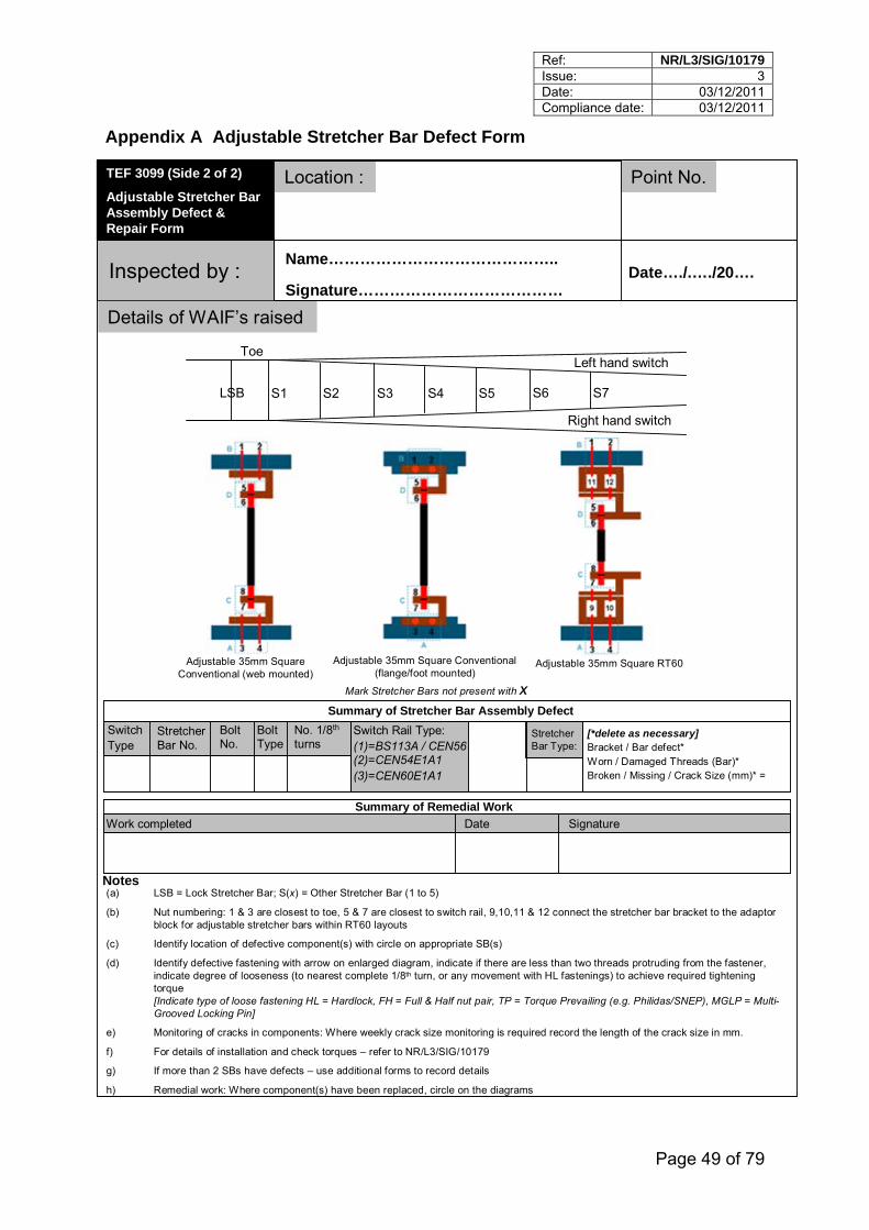
Appendix A Adjustable Stretcher Bar Defect Form
TEF 3099 (Side 2 of 2)
Adjustable Stretcher Bar Assembly Defect & Repair Form
Location : Point No.
Inspected by :Name……………………………………..
Date…./.…./20….Signature…………………………………
Details of WAIF’s raised
S1 S2 S3 S4 S5LSB
Left hand switch
Right hand switch
Toe
Adjustable 35mm Square Conventional (web mounted)
Adjustable 35mm Square Conventional (flange/foot mounted)
Adjustable 35mm Square RT60
Mark Stretcher Bars not present with X
Summary of Stretcher Bar Assembly Defect
Summary of Remedial Work
Switch Type
Stretcher Bar No.
Bolt No.
Bolt Type
No. 1/8th
turns Switch Rail Type:(1)=BS113A / CEN56 (2)=CEN54E1A1(3)=CEN60E1A1
[*delete as necessary]Bracket / Bar defect*Worn / Damaged Threads (Bar)*Broken / Missing / Crack Size (mm)* =
Work completed Date Signature
Notes(a) LSB = Lock Stretcher Bar; S(x) = Other Stretcher Bar (1 to 5)
(b) Nut numbering: 1 & 3 are closest to toe, 5 & 7 are closest to switch rail, 9,10,11 & 12 connect the stretcher bar bracket to the adaptor block for adjustable stretcher bars within RT60 layouts
(c) Identify location of defective component(s) with circle on appropriate SB(s)
(d) Identify defective fastening with arrow on enlarged diagram, indicate if there are less than two threads protruding from the fastener, indicate degree of looseness (to nearest complete 1/8th turn, or any movement with HL fastenings) to achieve required tightening torque[Indicate type of loose fastening HL = Hardlock, FH = Full & Half nut pair, TP = Torque Prevailing (e.g. Philidas/SNEP), MGLP = Multi-Grooved Locking Pin]
e) Monitoring of cracks in components: Where weekly crack size monitoring is required record the length of the crack size in mm.
f) For details of installation and check torques – refer to NR/L3/SIG/10179
g) If more than 2 SBs have defects – use additional forms to record details
h) Remedial work: Where component(s) have been replaced, circle on the diagrams
S6 S7
Stretcher Bar Type:
Ref: NR/L3/SIG/10179 Issue: 3 Date: 03/12/2011 Compliance date: 03/12/2011
Page 50 of 79
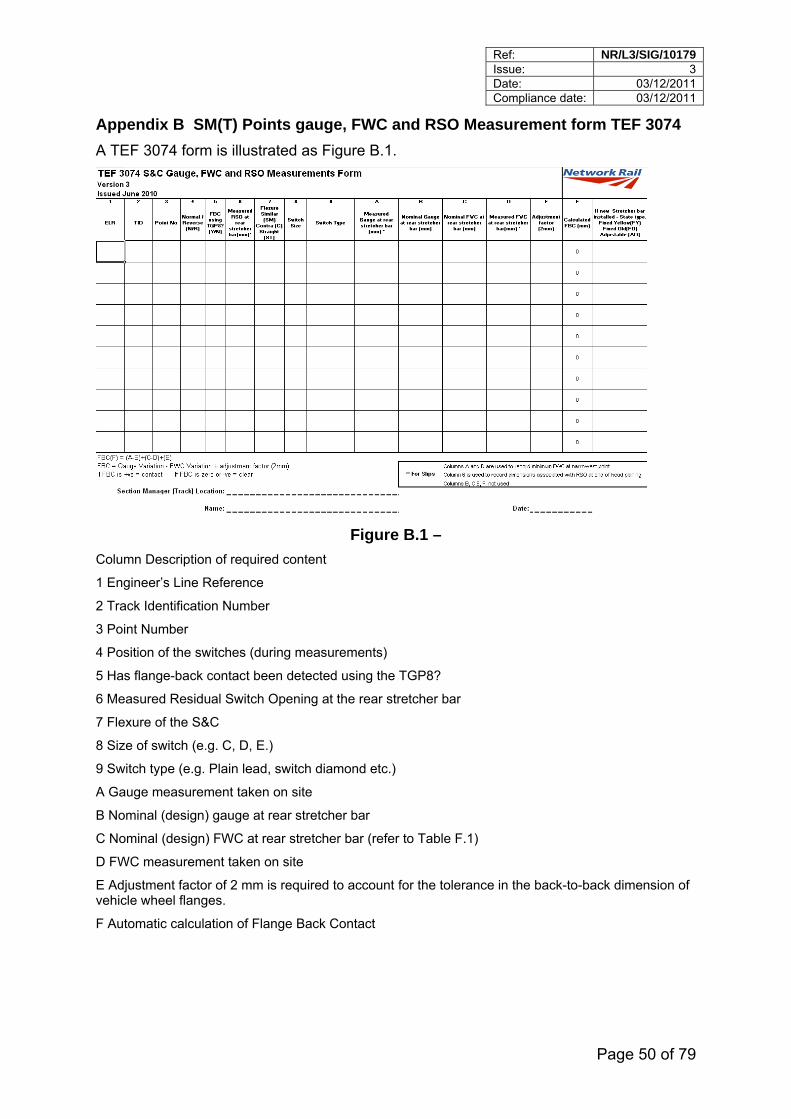
Appendix B SM(T) Points gauge, FWC and RSO Measurement form TEF 3074
A TEF 3074 form is illustrated as Figure B.1.
Figure B.1 –
Column Description of required content
1 Engineer’s Line Reference
2 Track Identification Number
3 Point Number
4 Position of the switches (during measurements)
5 Has flange-back contact been detected using the TGP8?
6 Measured Residual Switch Opening at the rear stretcher bar
7 Flexure of the S&C
8 Size of switch (e.g. C, D, E.)
9 Switch type (e.g. Plain lead, switch diamond etc.)
A Gauge measurement taken on site
B Nominal (design) gauge at rear stretcher bar
C Nominal (design) FWC at rear stretcher bar (refer to Table F.1)
D FWC measurement taken on site
E Adjustment factor of 2 mm is required to account for the tolerance in the back-to-back dimension of vehicle wheel flanges.
F Automatic calculation of Flange Back Contact
Ref: NR/L3/SIG/10179 Issue: 3 Date: 03/12/2011 Compliance date: 03/12/2011
Page 51 of 79
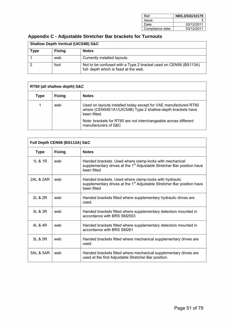
Appendix C - Adjustable Stretcher Bar brackets for Turnouts
Shallow Depth Vertical (UIC54B) S&C
Type Fixing Notes
1 web Currently installed layouts.
2 foot Not to be confused with a Type 2 bracket used on CEN56 (BS113A) full- depth which is fixed at the web.
RT60 (all shallow depth) S&C
Type Fixing Notes
1 web Used on layouts installed today except for VAE manufactured RT60 where (CEN54E1A1/UIC54B) Type 2 shallow-depth brackets have been fitted.
Note: brackets for RT60 are not interchangeable across different manufacturers of S&C
Full Depth CEN56 (BS113A) S&C
Type Fixing Notes
1L & 1R web Handed brackets. Used where clamp-locks with mechanical supplementary drives at the 1st Adjustable Stretcher Bar position have been fitted
2AL & 2AR web Handed brackets. Used where clamp-locks with hydraulic supplementary drives at the 1st Adjustable Stretcher Bar position have been fitted
2L & 2R web Handed brackets fitted where supplementary hydraulic drives are used.
3L & 3R web Handed brackets fitted where supplementary detectors mounted in accordance with BRS SM2503
4L & 4R web Handed brackets fitted where supplementary detectors mounted in accordance with BRS SM261
5L & 5R web Handed brackets fitted where mechanical supplementary drives are used.
5AL & 5AR web Handed brackets fitted where mechanical supplementary drives are used at the first Adjustable Stretcher Bar position.
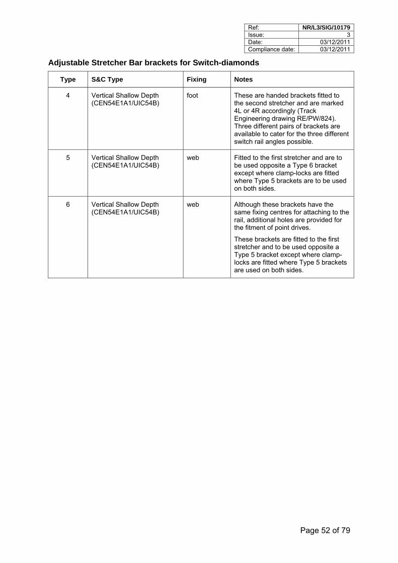
Ref: NR/L3/SIG/10179 Issue: 3 Date: 03/12/2011 Compliance date: 03/12/2011
Page 52 of 79
Adjustable Stretcher Bar brackets for Switch-diamonds
Type S&C Type Fixing Notes
4 Vertical Shallow Depth (CEN54E1A1/UIC54B)
foot These are handed brackets fitted to the second stretcher and are marked 4L or 4R accordingly (Track Engineering drawing RE/PW/824). Three different pairs of brackets are available to cater for the three different switch rail angles possible.
5 Vertical Shallow Depth (CEN54E1A1/UIC54B)
web Fitted to the first stretcher and are to be used opposite a Type 6 bracket except where clamp-locks are fitted where Type 5 brackets are to be used on both sides.
6 Vertical Shallow Depth (CEN54E1A1/UIC54B)
web Although these brackets have the same fixing centres for attaching to the rail, additional holes are provided for the fitment of point drives.
These brackets are fitted to the first stretcher and to be used opposite a Type 5 bracket except where clamp-locks are fitted where Type 5 brackets are used on both sides.
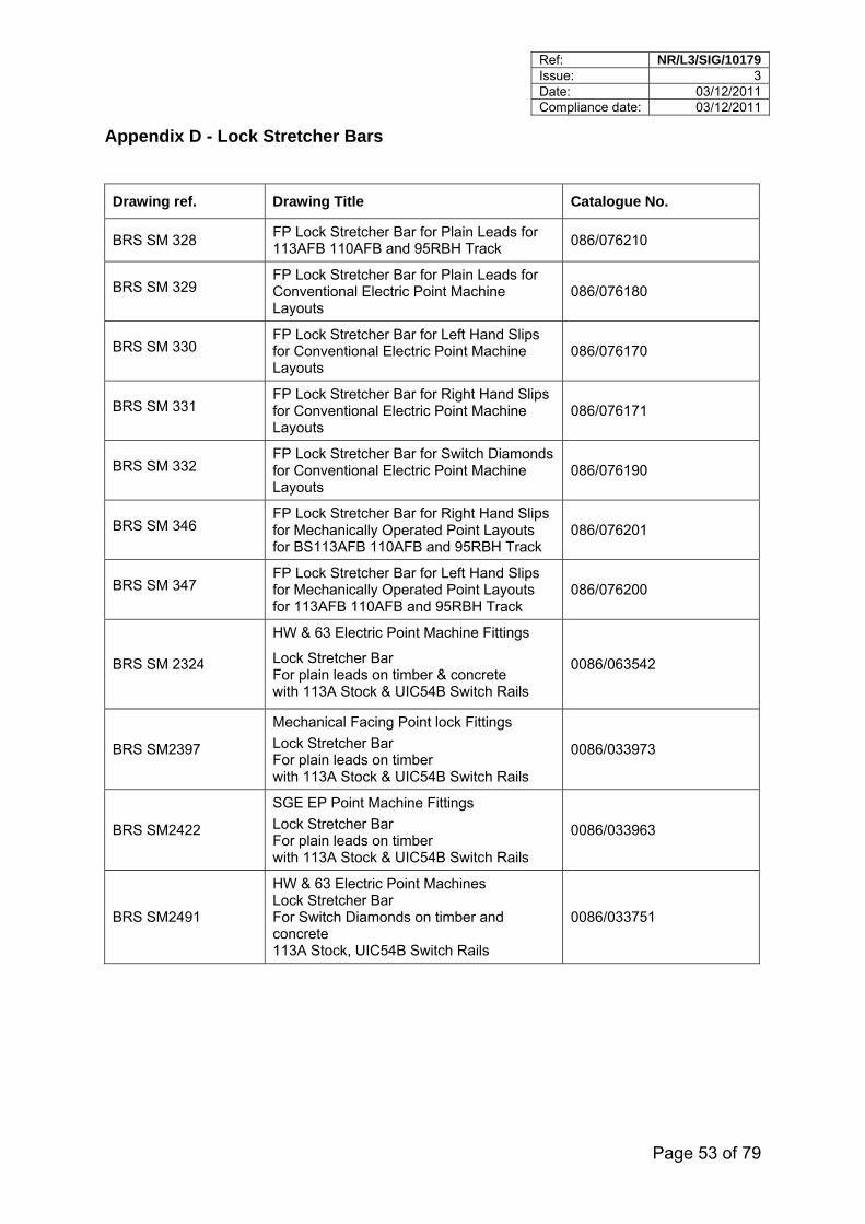
Ref: NR/L3/SIG/10179 Issue: 3 Date: 03/12/2011 Compliance date: 03/12/2011
Page 53 of 79
Appendix D - Lock Stretcher Bars
Drawing ref. Drawing Title Catalogue No.
BRS SM 328 FP Lock Stretcher Bar for Plain Leads for 113AFB 110AFB and 95RBH Track
086/076210
BRS SM 329 FP Lock Stretcher Bar for Plain Leads for Conventional Electric Point Machine Layouts
086/076180
BRS SM 330 FP Lock Stretcher Bar for Left Hand Slips for Conventional Electric Point Machine Layouts
086/076170
BRS SM 331 FP Lock Stretcher Bar for Right Hand Slips for Conventional Electric Point Machine Layouts
086/076171
BRS SM 332 FP Lock Stretcher Bar for Switch Diamonds for Conventional Electric Point Machine Layouts
086/076190
BRS SM 346 FP Lock Stretcher Bar for Right Hand Slips for Mechanically Operated Point Layouts for BS113AFB 110AFB and 95RBH Track
086/076201
BRS SM 347 FP Lock Stretcher Bar for Left Hand Slips for Mechanically Operated Point Layouts for 113AFB 110AFB and 95RBH Track
086/076200
BRS SM 2324
HW & 63 Electric Point Machine Fittings
Lock Stretcher Bar For plain leads on timber & concrete with 113A Stock & UIC54B Switch Rails
0086/063542
BRS SM2397
Mechanical Facing Point lock Fittings
Lock Stretcher Bar For plain leads on timber with 113A Stock & UIC54B Switch Rails
0086/033973
BRS SM2422
SGE EP Point Machine Fittings
Lock Stretcher Bar For plain leads on timber with 113A Stock & UIC54B Switch Rails
0086/033963
BRS SM2491
HW & 63 Electric Point Machines Lock Stretcher Bar For Switch Diamonds on timber and concrete 113A Stock, UIC54B Switch Rails
0086/033751
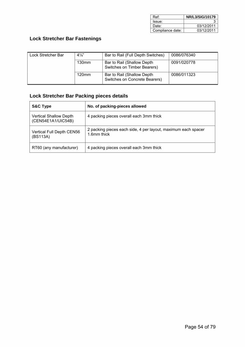
Ref: NR/L3/SIG/10179 Issue: 3 Date: 03/12/2011 Compliance date: 03/12/2011
Page 54 of 79
Lock Stretcher Bar Fastenings
4¼” Bar to Rail (Full Depth Switches) 0086/076340
130mm Bar to Rail (Shallow Depth Switches on Timber Bearers)
0091/020778
Lock Stretcher Bar
120mm Bar to Rail (Shallow Depth Switches on Concrete Bearers)
0086/011323
Lock Stretcher Bar Packing pieces details
S&C Type No. of packing-pieces allowed
Vertical Shallow Depth (CEN54E1A1/UIC54B)
4 packing pieces overall each 3mm thick
Vertical Full Depth CEN56 (BS113A)
2 packing pieces each side, 4 per layout, maximum each spacer 1.6mm thick
RT60 (any manufacturer) 4 packing pieces overall each 3mm thick
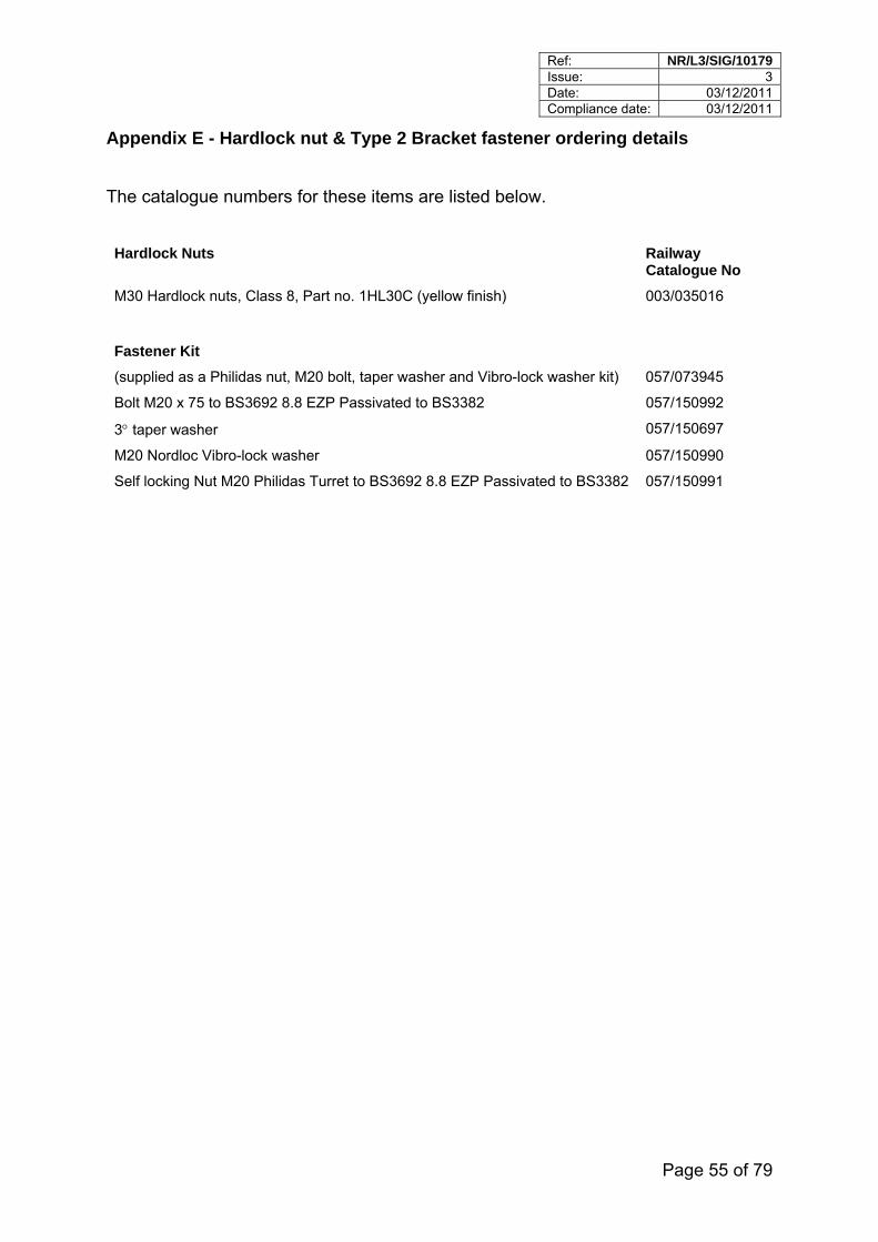
Ref: NR/L3/SIG/10179 Issue: 3 Date: 03/12/2011 Compliance date: 03/12/2011
Page 55 of 79
Appendix E - Hardlock nut & Type 2 Bracket fastener ordering details
The catalogue numbers for these items are listed below.
Hardlock Nuts Railway Catalogue No
M30 Hardlock nuts, Class 8, Part no. 1HL30C (yellow finish) 003/035016
Fastener Kit
(supplied as a Philidas nut, M20 bolt, taper washer and Vibro-lock washer kit) 057/073945
Bolt M20 x 75 to BS3692 8.8 EZP Passivated to BS3382 057/150992
3 taper washer 057/150697
M20 Nordloc Vibro-lock washer 057/150990
Self locking Nut M20 Philidas Turret to BS3692 8.8 EZP Passivated to BS3382 057/150991
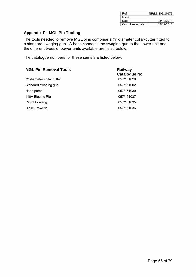
Ref: NR/L3/SIG/10179 Issue: 3 Date: 03/12/2011 Compliance date: 03/12/2011
Page 56 of 79
Appendix F - MGL Pin Tooling
The tools needed to remove MGL pins comprise a ¾” diameter collar-cutter fitted to a standard swaging-gun. A hose connects the swaging gun to the power unit and the different types of power units available are listed below. The catalogue numbers for these items are listed below.
MGL Pin Removal Tools Railway Catalogue No
¾” diameter collar cutter 057/151020
Standard swaging gun 057/151002
Hand pump 057/151030
110V Electric Rig 057/151037
Petrol Powerig 057/151035
Diesel Powerig 057/151036
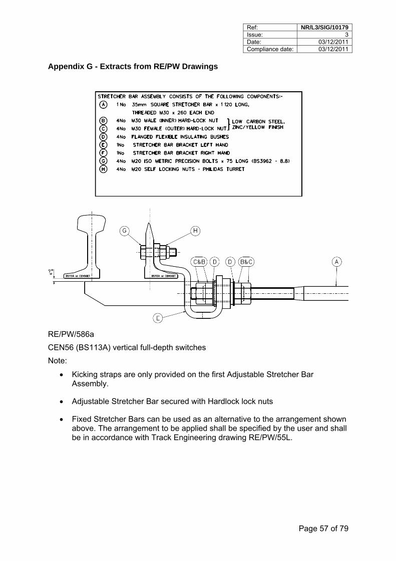
Ref: NR/L3/SIG/10179 Issue: 3 Date: 03/12/2011 Compliance date: 03/12/2011
Page 57 of 79
Appendix G - Extracts from RE/PW Drawings
RE/PW/586a
CEN56 (BS113A) vertical full-depth switches
Note:
Kicking straps are only provided on the first Adjustable Stretcher Bar Assembly.
Adjustable Stretcher Bar secured with Hardlock lock nuts
Fixed Stretcher Bars can be used as an alternative to the arrangement shown above. The arrangement to be applied shall be specified by the user and shall be in accordance with Track Engineering drawing RE/PW/55L.
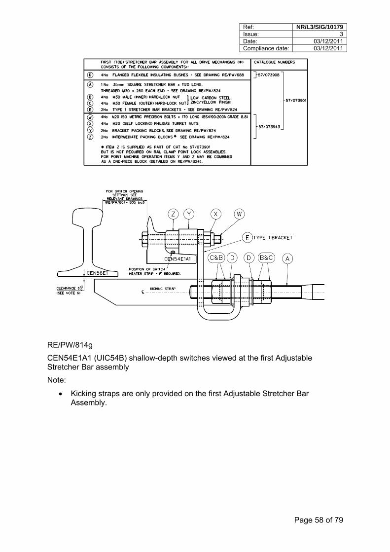
Ref: NR/L3/SIG/10179 Issue: 3 Date: 03/12/2011 Compliance date: 03/12/2011
Page 58 of 79
RE/PW/814g
CEN54E1A1 (UIC54B) shallow-depth switches viewed at the first Adjustable Stretcher Bar assembly
Note:
Kicking straps are only provided on the first Adjustable Stretcher Bar Assembly.
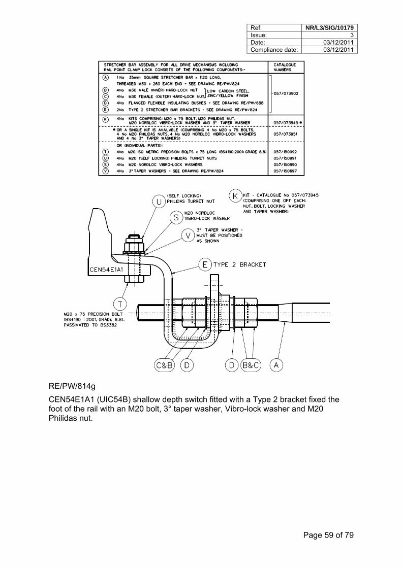
Ref: NR/L3/SIG/10179 Issue: 3 Date: 03/12/2011 Compliance date: 03/12/2011
Page 59 of 79
RE/PW/814g
CEN54E1A1 (UIC54B) shallow depth switch fitted with a Type 2 bracket fixed the foot of the rail with an M20 bolt, 3° taper washer, Vibro-lock washer and M20 Philidas nut.
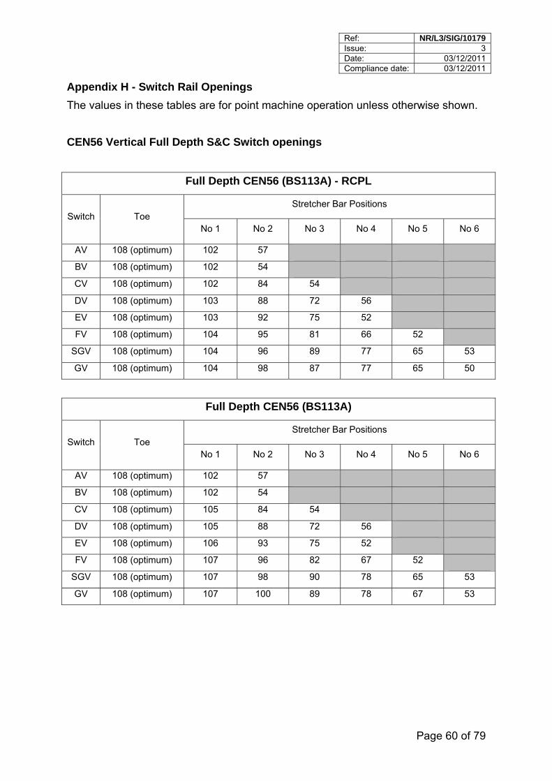
Ref: NR/L3/SIG/10179 Issue: 3 Date: 03/12/2011 Compliance date: 03/12/2011
Page 60 of 79
Appendix H - Switch Rail Openings
The values in these tables are for point machine operation unless otherwise shown.
CEN56 Vertical Full Depth S&C Switch openings
Full Depth CEN56 (BS113A) - RCPL
Stretcher Bar Positions Switch Toe
No 1 No 2 No 3 No 4 No 5 No 6
AV 108 (optimum) 102 57
BV 108 (optimum) 102 54
CV 108 (optimum) 102 84 54
DV 108 (optimum) 103 88 72 56
EV 108 (optimum) 103 92 75 52
FV 108 (optimum) 104 95 81 66 52
SGV 108 (optimum) 104 96 89 77 65 53
GV 108 (optimum) 104 98 87 77 65 50
Full Depth CEN56 (BS113A)
Stretcher Bar Positions Switch Toe
No 1 No 2 No 3 No 4 No 5 No 6
AV 108 (optimum) 102 57
BV 108 (optimum) 102 54
CV 108 (optimum) 105 84 54
DV 108 (optimum) 105 88 72 56
EV 108 (optimum) 106 93 75 52
FV 108 (optimum) 107 96 82 67 52
SGV 108 (optimum) 107 98 90 78 65 53
GV 108 (optimum) 107 100 89 78 67 53
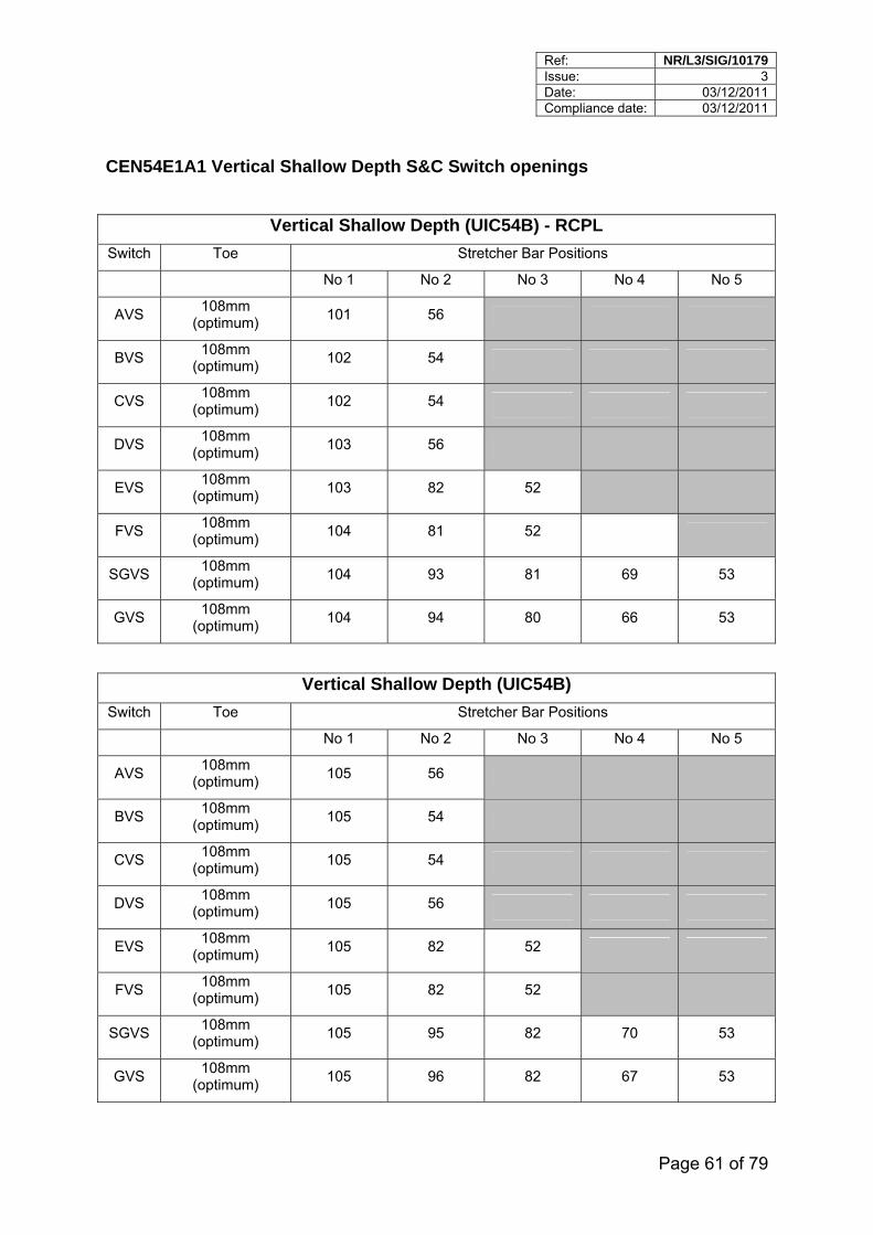
Ref: NR/L3/SIG/10179 Issue: 3 Date: 03/12/2011 Compliance date: 03/12/2011
Page 61 of 79
CEN54E1A1 Vertical Shallow Depth S&C Switch openings
Vertical Shallow Depth (UIC54B) - RCPL
Switch Toe Stretcher Bar Positions
No 1 No 2 No 3 No 4 No 5
AVS 108mm
(optimum) 101 56
BVS 108mm
(optimum) 102 54
CVS 108mm
(optimum) 102 54
DVS 108mm
(optimum) 103 56
EVS 108mm
(optimum) 103 82 52
FVS 108mm
(optimum) 104 81 52
SGVS 108mm
(optimum) 104 93 81 69 53
GVS 108mm
(optimum) 104 94 80 66 53
Vertical Shallow Depth (UIC54B)
Switch Toe Stretcher Bar Positions
No 1 No 2 No 3 No 4 No 5
AVS 108mm
(optimum) 105 56
BVS 108mm
(optimum) 105 54
CVS 108mm
(optimum) 105 54
DVS 108mm
(optimum) 105 56
EVS 108mm
(optimum) 105 82 52
FVS 108mm
(optimum) 105 82 52
SGVS 108mm
(optimum) 105 95 82 70 53
GVS 108mm
(optimum) 105 96 82 67 53
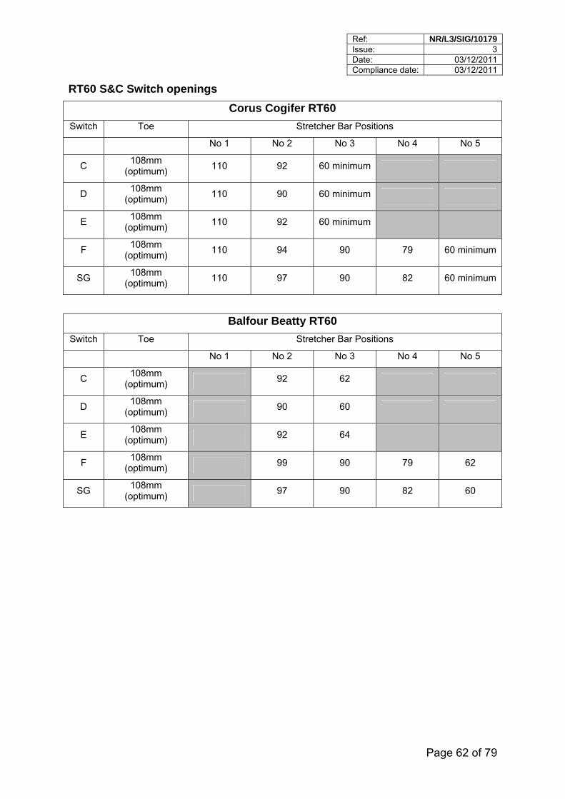
Ref: NR/L3/SIG/10179 Issue: 3 Date: 03/12/2011 Compliance date: 03/12/2011
Page 62 of 79
RT60 S&C Switch openings
Corus Cogifer RT60
Switch Toe Stretcher Bar Positions
No 1 No 2 No 3 No 4 No 5
C 108mm
(optimum) 110 92 60 minimum
D 108mm
(optimum) 110 90 60 minimum
E 108mm
(optimum) 110 92 60 minimum
F 108mm
(optimum) 110 94 90 79 60 minimum
SG 108mm
(optimum) 110 97 90 82 60 minimum
Balfour Beatty RT60
Switch Toe Stretcher Bar Positions
No 1 No 2 No 3 No 4 No 5
C 108mm
(optimum) 92 62
D 108mm
(optimum) 90 60
E 108mm
(optimum) 92 64
F 108mm
(optimum) 99 90 79 62
SG 108mm
(optimum) 97 90 82 60
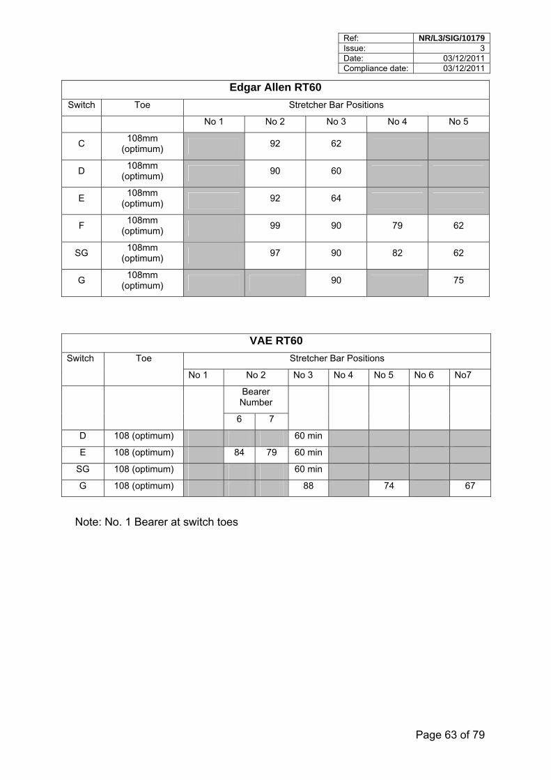
Ref: NR/L3/SIG/10179 Issue: 3 Date: 03/12/2011 Compliance date: 03/12/2011
Page 63 of 79
Edgar Allen RT60
Switch Toe Stretcher Bar Positions
No 1 No 2 No 3 No 4 No 5
C 108mm
(optimum) 92 62
D 108mm
(optimum) 90 60
E 108mm
(optimum) 92 64
F 108mm
(optimum) 99 90 79 62
SG 108mm
(optimum) 97 90 82 62
G 108mm
(optimum) 90 75
VAE RT60
Stretcher Bar Positions Switch Toe
No 1 No 2 No 3 No 4 No 5 No 6 No7
Bearer Number
6 7
D 108 (optimum) 60 min
E 108 (optimum) 84 79 60 min
SG 108 (optimum) 60 min
G 108 (optimum) 88 74 67
Note: No. 1 Bearer at switch toes
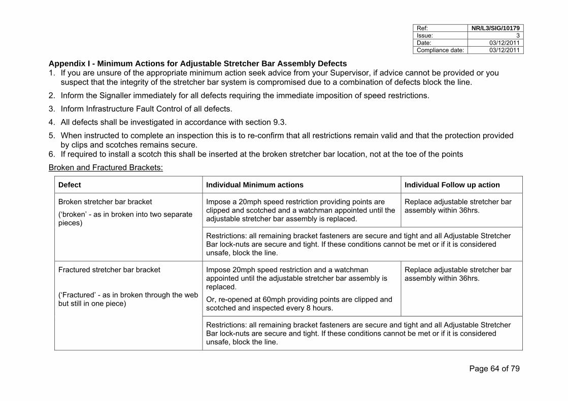
Ref: NR/L3/SIG/10179 Issue: 3 Date: 03/12/2011 Compliance date: 03/12/2011
Page 64 of 79
Appendix I - Minimum Actions for Adjustable Stretcher Bar Assembly Defects 1. If you are unsure of the appropriate minimum action seek advice from your Supervisor, if advice cannot be provided or you
suspect that the integrity of the stretcher bar system is compromised due to a combination of defects block the line.
2. Inform the Signaller immediately for all defects requiring the immediate imposition of speed restrictions.
3. Inform Infrastructure Fault Control of all defects.
4. All defects shall be investigated in accordance with section 9.3.
5. When instructed to complete an inspection this is to re-confirm that all restrictions remain valid and that the protection provided by clips and scotches remains secure.
6. If required to install a scotch this shall be inserted at the broken stretcher bar location, not at the toe of the points
Broken and Fractured Brackets:
Defect Individual Minimum actions Individual Follow up action
Impose a 20mph speed restriction providing points are clipped and scotched and a watchman appointed until the adjustable stretcher bar assembly is replaced.
Replace adjustable stretcher bar assembly within 36hrs.
Broken stretcher bar bracket
(‘broken’ - as in broken into two separate pieces)
Restrictions: all remaining bracket fasteners are secure and tight and all Adjustable Stretcher Bar lock-nuts are secure and tight. If these conditions cannot be met or if it is considered unsafe, block the line.
Impose 20mph speed restriction and a watchman appointed until the adjustable stretcher bar assembly is replaced.
Or, re-opened at 60mph providing points are clipped and scotched and inspected every 8 hours.
Replace adjustable stretcher bar assembly within 36hrs.
Fractured stretcher bar bracket
(‘Fractured’ - as in broken through the web but still in one piece)
Restrictions: all remaining bracket fasteners are secure and tight and all Adjustable Stretcher Bar lock-nuts are secure and tight. If these conditions cannot be met or if it is considered unsafe, block the line.
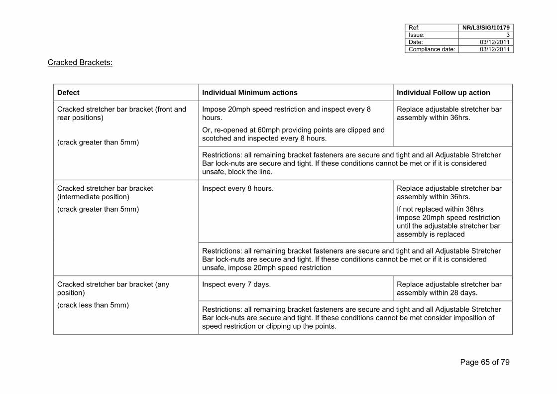
Ref: NR/L3/SIG/10179 Issue: 3 Date: 03/12/2011 Compliance date: 03/12/2011
Page 65 of 79
Cracked Brackets:
Defect Individual Minimum actions Individual Follow up action
Impose 20mph speed restriction and inspect every 8 hours.
Or, re-opened at 60mph providing points are clipped and scotched and inspected every 8 hours.
Replace adjustable stretcher bar assembly within 36hrs.
Cracked stretcher bar bracket (front and rear positions)
(crack greater than 5mm)
Restrictions: all remaining bracket fasteners are secure and tight and all Adjustable Stretcher Bar lock-nuts are secure and tight. If these conditions cannot be met or if it is considered unsafe, block the line.
Inspect every 8 hours.
Replace adjustable stretcher bar assembly within 36hrs.
If not replaced within 36hrs impose 20mph speed restriction until the adjustable stretcher bar assembly is replaced
Cracked stretcher bar bracket (intermediate position)
(crack greater than 5mm)
Restrictions: all remaining bracket fasteners are secure and tight and all Adjustable Stretcher Bar lock-nuts are secure and tight. If these conditions cannot be met or if it is considered unsafe, impose 20mph speed restriction
Inspect every 7 days. Replace adjustable stretcher bar assembly within 28 days.
Cracked stretcher bar bracket (any position)
(crack less than 5mm) Restrictions: all remaining bracket fasteners are secure and tight and all Adjustable Stretcher Bar lock-nuts are secure and tight. If these conditions cannot be met consider imposition of speed restriction or clipping up the points.
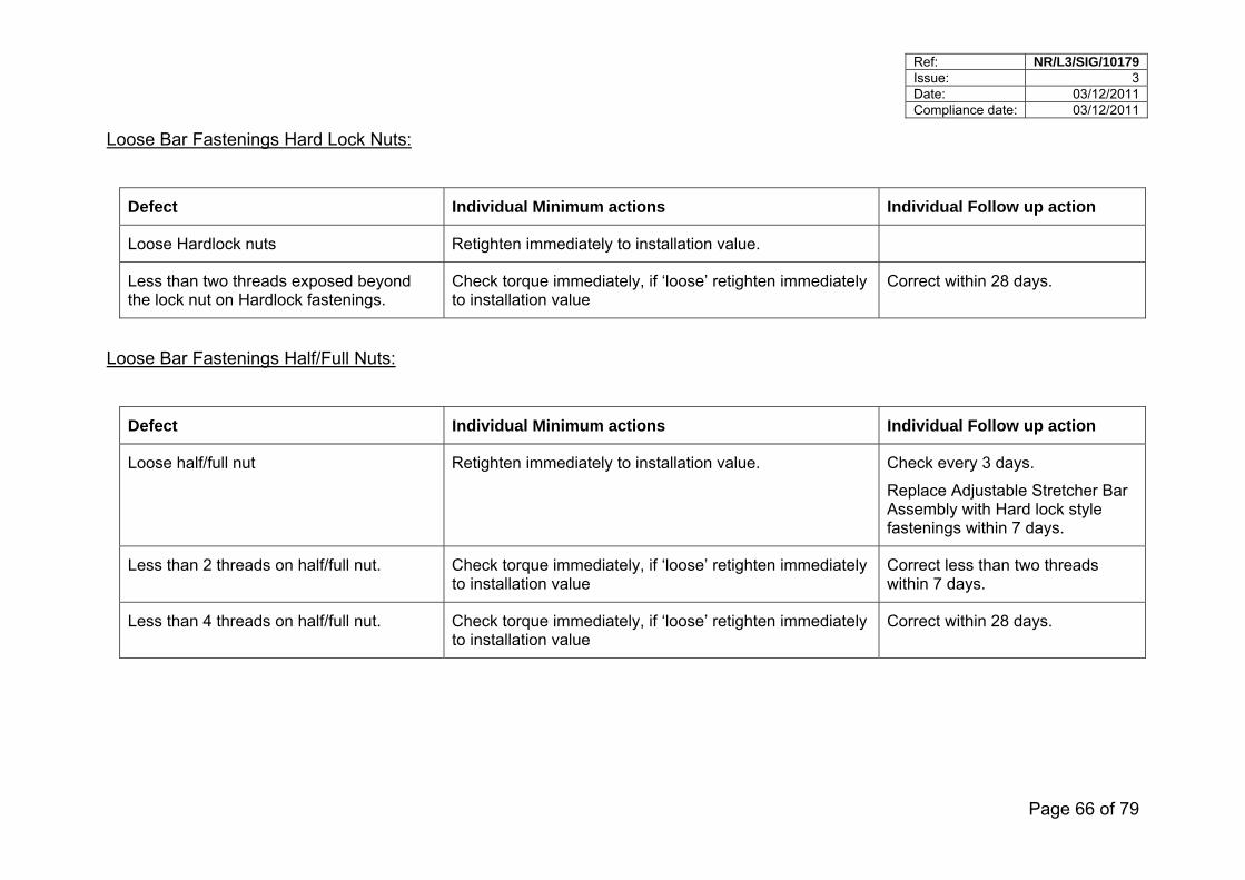
Ref: NR/L3/SIG/10179 Issue: 3 Date: 03/12/2011 Compliance date: 03/12/2011
Page 66 of 79
Loose Bar Fastenings Hard Lock Nuts:
Defect Individual Minimum actions Individual Follow up action
Loose Hardlock nuts Retighten immediately to installation value.
Less than two threads exposed beyond the lock nut on Hardlock fastenings.
Check torque immediately, if ‘loose’ retighten immediately to installation value
Correct within 28 days.
Loose Bar Fastenings Half/Full Nuts:
Defect Individual Minimum actions Individual Follow up action
Loose half/full nut Retighten immediately to installation value.
Check every 3 days.
Replace Adjustable Stretcher Bar Assembly with Hard lock style fastenings within 7 days.
Less than 2 threads on half/full nut. Check torque immediately, if ‘loose’ retighten immediately to installation value
Correct less than two threads within 7 days.
Less than 4 threads on half/full nut. Check torque immediately, if ‘loose’ retighten immediately to installation value
Correct within 28 days.
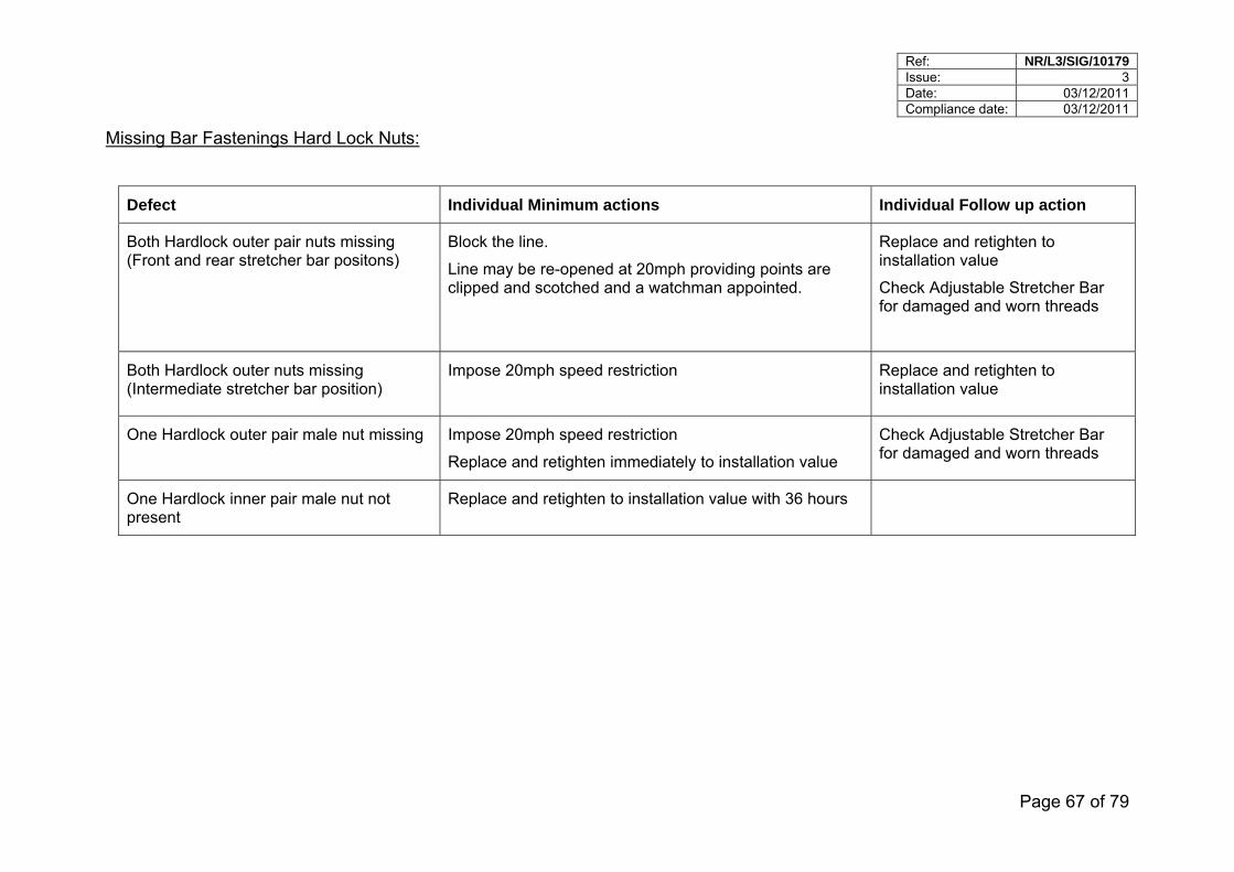
Ref: NR/L3/SIG/10179 Issue: 3 Date: 03/12/2011 Compliance date: 03/12/2011
Page 67 of 79
Missing Bar Fastenings Hard Lock Nuts:
Defect Individual Minimum actions Individual Follow up action
Both Hardlock outer pair nuts missing (Front and rear stretcher bar positons)
Block the line.
Line may be re-opened at 20mph providing points are clipped and scotched and a watchman appointed.
Replace and retighten to installation value
Check Adjustable Stretcher Bar for damaged and worn threads
Both Hardlock outer nuts missing (Intermediate stretcher bar position)
Impose 20mph speed restriction
Replace and retighten to installation value
One Hardlock outer pair male nut missing Impose 20mph speed restriction
Replace and retighten immediately to installation value
Check Adjustable Stretcher Bar for damaged and worn threads
One Hardlock inner pair male nut not present
Replace and retighten to installation value with 36 hours
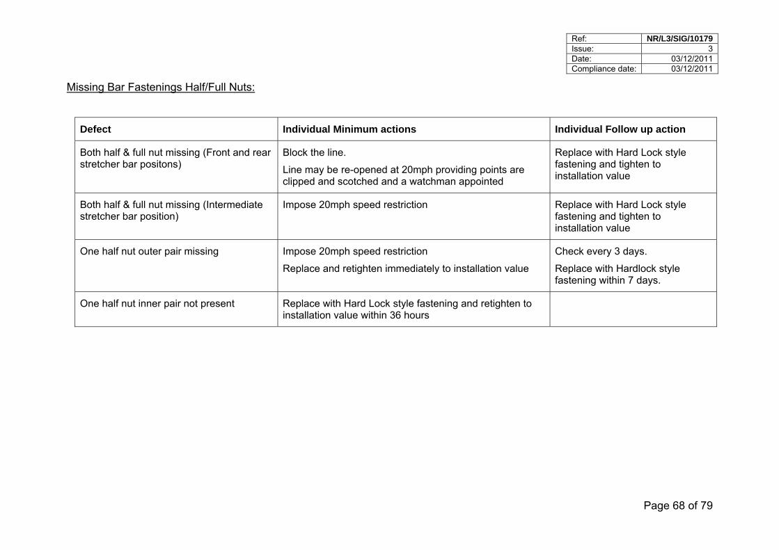
Ref: NR/L3/SIG/10179 Issue: 3 Date: 03/12/2011 Compliance date: 03/12/2011
Page 68 of 79
Missing Bar Fastenings Half/Full Nuts:
Defect Individual Minimum actions Individual Follow up action
Both half & full nut missing (Front and rear stretcher bar positons)
Block the line.
Line may be re-opened at 20mph providing points are clipped and scotched and a watchman appointed
Replace with Hard Lock style fastening and tighten to installation value
Both half & full nut missing (Intermediate stretcher bar position)
Impose 20mph speed restriction
Replace with Hard Lock style fastening and tighten to installation value
One half nut outer pair missing Impose 20mph speed restriction
Replace and retighten immediately to installation value
Check every 3 days.
Replace with Hardlock style fastening within 7 days.
One half nut inner pair not present Replace with Hard Lock style fastening and retighten to installation value within 36 hours
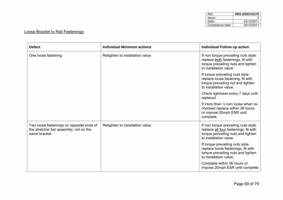
Ref: NR/L3/SIG/10179 Issue: 3 Date: 03/12/2011 Compliance date: 03/12/2011
Page 69 of 79
Loose Bracket to Rail Fastenings:
Defect Individual Minimum actions Individual Follow up action
One loose fastening Retighten to installation value If non torque prevailing nuts style: replace both fastenings, fit with torque prevailing nuts and tighten to installation value
If torque prevailing nuts style replace loose fastening, fit with torque prevailing nut and tighten to installation value.
Check tightness every 7 days until replaced.
If more than ¼ turn loose when re-checked replace within 36 hours or impose 20mph ESR until complete
Two loose fastenings on opposite ends of the stretcher bar assembly, not on the same bracket
Retighten to installation value If non torque prevailing nuts style: replace all four fastenings, fit with torque prevailing nuts and tighten to installation value
If torque prevailing nuts style replace loose fastenings, fit with torque prevailing nuts and tighten to installation value.
Complete within 36 hours or impose 20mph ESR until complete
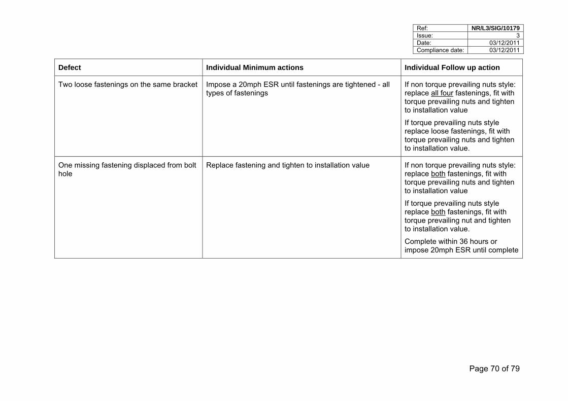
Ref: NR/L3/SIG/10179 Issue: 3 Date: 03/12/2011 Compliance date: 03/12/2011
Page 70 of 79
Defect Individual Minimum actions Individual Follow up action
Two loose fastenings on the same bracket Impose a 20mph ESR until fastenings are tightened - all types of fastenings
If non torque prevailing nuts style: replace all four fastenings, fit with torque prevailing nuts and tighten to installation value
If torque prevailing nuts style replace loose fastenings, fit with torque prevailing nuts and tighten to installation value.
One missing fastening displaced from bolt hole
Replace fastening and tighten to installation value If non torque prevailing nuts style: replace both fastenings, fit with torque prevailing nuts and tighten to installation value
If torque prevailing nuts style replace both fastenings, fit with torque prevailing nut and tighten to installation value.
Complete within 36 hours or impose 20mph ESR until complete
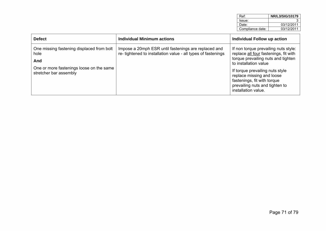
Ref: NR/L3/SIG/10179 Issue: 3 Date: 03/12/2011 Compliance date: 03/12/2011
Page 71 of 79
Defect Individual Minimum actions Individual Follow up action
One missing fastening displaced from bolt hole
And
One or more fastenings loose on the same stretcher bar assembly
Impose a 20mph ESR until fastenings are replaced and re- tightened to installation value - all types of fastenings
If non torque prevailing nuts style: replace all four fastenings, fit with torque prevailing nuts and tighten to installation value
If torque prevailing nuts style replace missing and loose fastenings, fit with torque prevailing nuts and tighten to installation value.
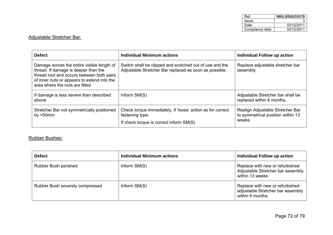
Ref: NR/L3/SIG/10179 Issue: 3 Date: 03/12/2011 Compliance date: 03/12/2011
Page 72 of 79
Adjustable Stretcher Bar:
Defect Individual Minimum actions Individual Follow up action
Damage across the entire visible length of thread. If damage is deeper than the thread root and occurs between both pairs of inner nuts or appears to extend into the area where the nuts are fitted
Switch shall be clipped and scotched out of use and the Adjustable Stretcher Bar replaced as soon as possible.
Replace adjustable stretcher bar assembly
If damage is less severe than described above
Inform SM(S) Adjustable Stretcher bar shall be replaced within 6 months.
Stretcher Bar not symmetrically positioned by >50mm
Check torque immediately, if ‘loose’ action as for correct fastening type.
If check torque is correct inform SM(S)
Realign Adjustable Stretcher Bar to symmetrical position within 13 weeks.
Rubber Bushes:
Defect Individual Minimum actions Individual Follow up action
Rubber Bush perished Inform SM(S) Replace with new or refurbished Adjustable Stretcher bar assembly within 13 weeks
Rubber Bush severely compressed Inform SM(S) Replace with new or refurbished adjustable Stretcher bar assembly within 6 months.
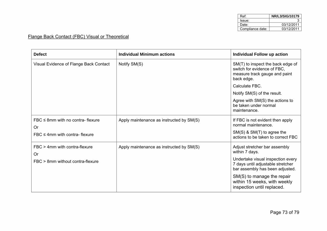
Ref: NR/L3/SIG/10179 Issue: 3 Date: 03/12/2011 Compliance date: 03/12/2011
Page 73 of 79
Flange Back Contact (FBC) Visual or Theoretical
Defect Individual Minimum actions Individual Follow up action
Visual Evidence of Flange Back Contact Notify SM(S) SM(T) to inspect the back edge of switch for evidence of FBC, measure track gauge and paint back edge.
Calculate FBC.
Notify SM(S) of the result.
Agree with SM(S) the actions to be taken under normal maintenance.
FBC ≤ 8mm with no contra- flexure
Or
FBC ≤ 4mm with contra- flexure
Apply maintenance as instructed by SM(S) If FBC is not evident then apply normal maintenance.
SM(S) & SM(T) to agree the actions to be taken to correct FBC
FBC > 4mm with contra-flexure
Or
FBC > 8mm without contra-flexure
Apply maintenance as instructed by SM(S) Adjust stretcher bar assembly within 7 days.
Undertake visual inspection every 7 days until adjustable stretcher bar assembly has been adjusted.
SM(S) to manage the repair within 15 weeks, with weekly inspection until replaced.
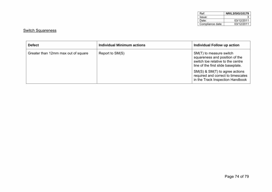
Ref: NR/L3/SIG/10179 Issue: 3 Date: 03/12/2011 Compliance date: 03/12/2011
Page 74 of 79
Switch Squareness
Defect Individual Minimum actions Individual Follow up action
Greater than 12mm max out of square Report to SM(S) SM(T) to measure switch squareness and position of the switch toe relative to the centre line of the first slide baseplate.
SM(S) & SM(T) to agree actions required and correct to timescales in the Track Inspection Handbook
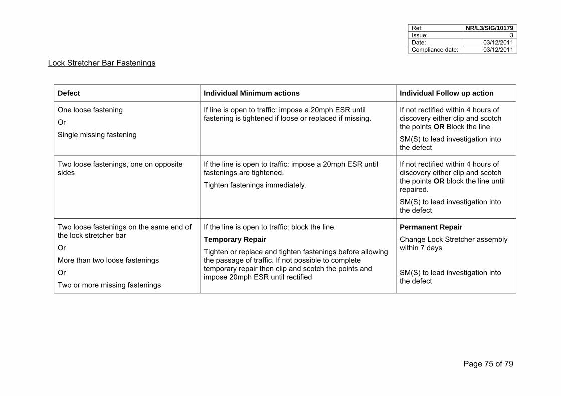
Ref: NR/L3/SIG/10179 Issue: 3 Date: 03/12/2011 Compliance date: 03/12/2011
Page 75 of 79
Lock Stretcher Bar Fastenings
Defect Individual Minimum actions Individual Follow up action
One loose fastening
Or
Single missing fastening
If line is open to traffic: impose a 20mph ESR until fastening is tightened if loose or replaced if missing.
If not rectified within 4 hours of discovery either clip and scotch the points OR Block the line
SM(S) to lead investigation into the defect
Two loose fastenings, one on opposite sides
If the line is open to traffic: impose a 20mph ESR until fastenings are tightened.
Tighten fastenings immediately.
If not rectified within 4 hours of discovery either clip and scotch the points OR block the line until repaired.
SM(S) to lead investigation into the defect
Two loose fastenings on the same end of the lock stretcher bar
Or
More than two loose fastenings
Or
Two or more missing fastenings
If the line is open to traffic: block the line.
Temporary Repair
Tighten or replace and tighten fastenings before allowing the passage of traffic. If not possible to complete temporary repair then clip and scotch the points and impose 20mph ESR until rectified
Permanent Repair
Change Lock Stretcher assembly within 7 days
SM(S) to lead investigation into the defect
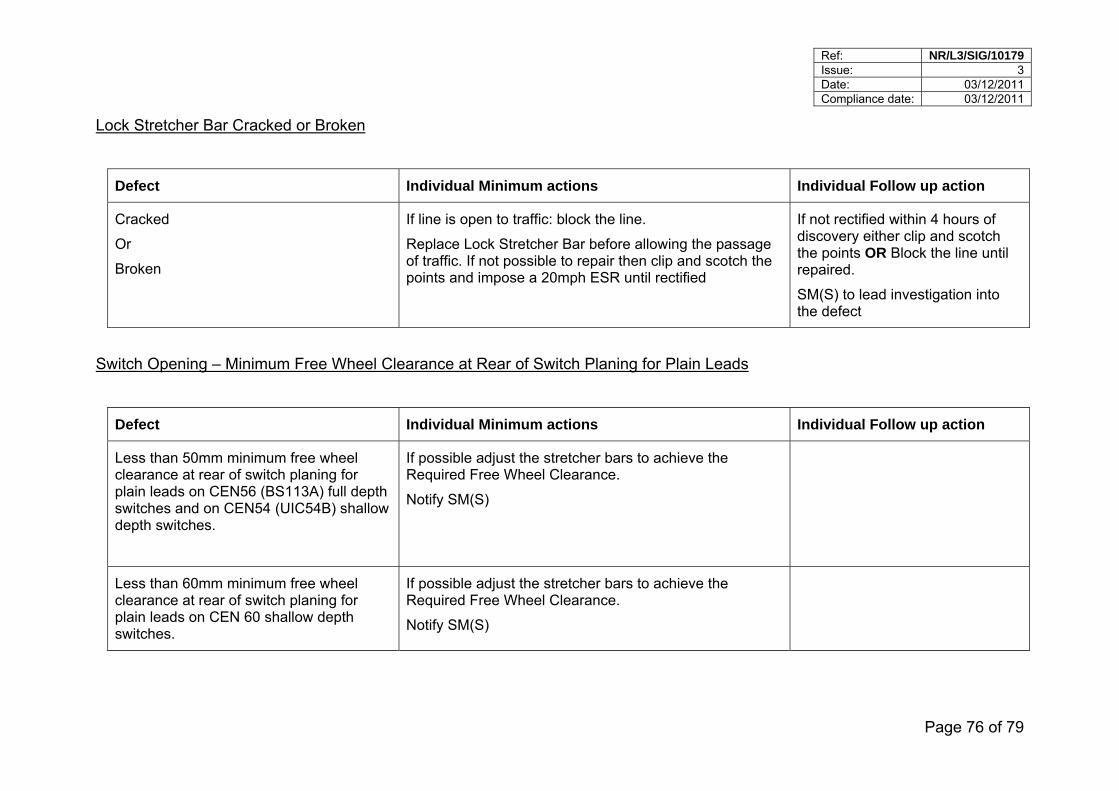
Ref: NR/L3/SIG/10179 Issue: 3 Date: 03/12/2011 Compliance date: 03/12/2011
Page 76 of 79
Lock Stretcher Bar Cracked or Broken
Defect Individual Minimum actions Individual Follow up action
Cracked
Or
Broken
If line is open to traffic: block the line.
Replace Lock Stretcher Bar before allowing the passage of traffic. If not possible to repair then clip and scotch the points and impose a 20mph ESR until rectified
If not rectified within 4 hours of discovery either clip and scotch the points OR Block the line until repaired.
SM(S) to lead investigation into the defect
Switch Opening – Minimum Free Wheel Clearance at Rear of Switch Planing for Plain Leads
Defect Individual Minimum actions Individual Follow up action
Less than 50mm minimum free wheel clearance at rear of switch planing for plain leads on CEN56 (BS113A) full depth switches and on CEN54 (UIC54B) shallow depth switches.
If possible adjust the stretcher bars to achieve the Required Free Wheel Clearance.
Notify SM(S)
Less than 60mm minimum free wheel clearance at rear of switch planing for plain leads on CEN 60 shallow depth switches.
If possible adjust the stretcher bars to achieve the Required Free Wheel Clearance.
Notify SM(S)
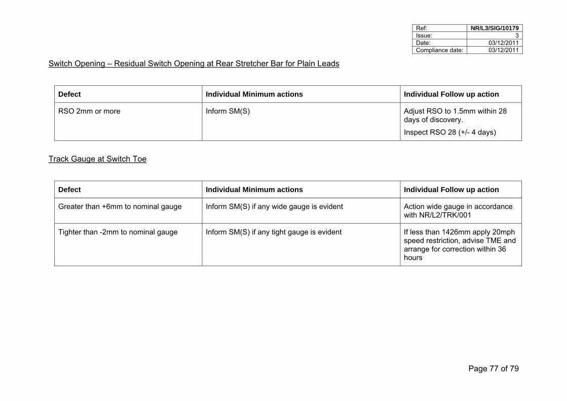
Ref: NR/L3/SIG/10179 Issue: 3 Date: 03/12/2011 Compliance date: 03/12/2011
Page 77 of 79
Switch Opening – Residual Switch Opening at Rear Stretcher Bar for Plain Leads
Defect Individual Minimum actions Individual Follow up action
RSO 2mm or more
Inform SM(S) Adjust RSO to 1.5mm within 28 days of discovery.
Inspect RSO 28 (+/- 4 days)
Track Gauge at Switch Toe
Defect Individual Minimum actions Individual Follow up action
Greater than +6mm to nominal gauge Inform SM(S) if any wide gauge is evident Action wide gauge in accordance with NR/L2/TRK/001
Tighter than -2mm to nominal gauge Inform SM(S) if any tight gauge is evident If less than 1426mm apply 20mph speed restriction, advise TME and arrange for correction within 36 hours
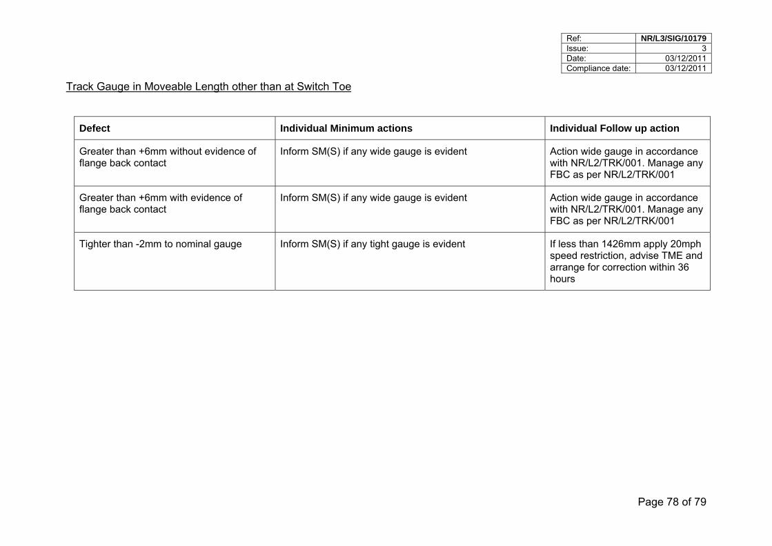
Ref: NR/L3/SIG/10179 Issue: 3 Date: 03/12/2011 Compliance date: 03/12/2011
Page 78 of 79
Track Gauge in Moveable Length other than at Switch Toe
Defect Individual Minimum actions Individual Follow up action
Greater than +6mm without evidence of flange back contact
Inform SM(S) if any wide gauge is evident Action wide gauge in accordance with NR/L2/TRK/001. Manage any FBC as per NR/L2/TRK/001
Greater than +6mm with evidence of flange back contact
Inform SM(S) if any wide gauge is evident Action wide gauge in accordance with NR/L2/TRK/001. Manage any FBC as per NR/L2/TRK/001
Tighter than -2mm to nominal gauge Inform SM(S) if any tight gauge is evident If less than 1426mm apply 20mph speed restriction, advise TME and arrange for correction within 36 hours
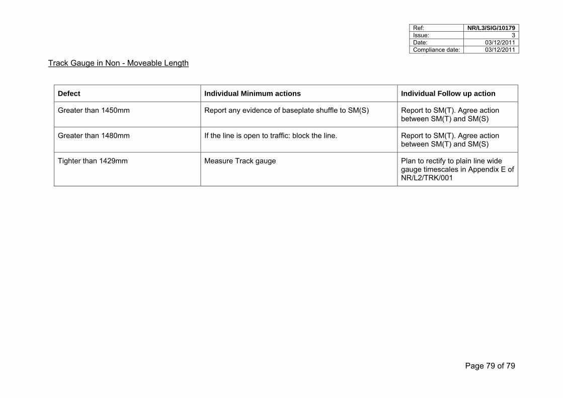
Ref: NR/L3/SIG/10179 Issue: 3 Date: 03/12/2011 Compliance date: 03/12/2011
Page 79 of 79
Track Gauge in Non - Moveable Length
Defect Individual Minimum actions Individual Follow up action
Greater than 1450mm Report any evidence of baseplate shuffle to SM(S) Report to SM(T). Agree action between SM(T) and SM(S)
Greater than 1480mm If the line is open to traffic: block the line. Report to SM(T). Agree action between SM(T) and SM(S)
Tighter than 1429mm Measure Track gauge Plan to rectify to plain line wide gauge timescales in Appendix E of NR/L2/TRK/001
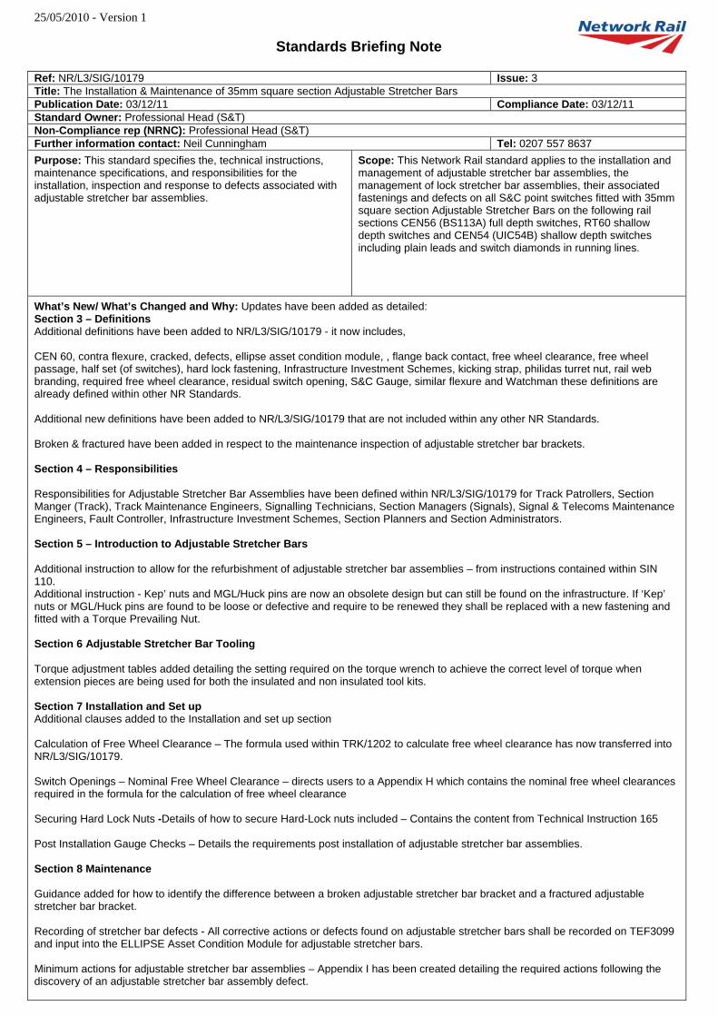
25/05/2010 - Version 1
Standards Briefing Note
Ref: NR/L3/SIG/10179 Issue: 3 Title: The Installation & Maintenance of 35mm square section Adjustable Stretcher Bars Publication Date: 03/12/11 Compliance Date: 03/12/11 Standard Owner: Professional Head (S&T) Non-Compliance rep (NRNC): Professional Head (S&T) Further information contact: Neil Cunningham Tel: 0207 557 8637 Purpose: This standard specifies the, technical instructions, maintenance specifications, and responsibilities for the installation, inspection and response to defects associated with adjustable stretcher bar assemblies.
Scope: This Network Rail standard applies to the installation and management of adjustable stretcher bar assemblies, the management of lock stretcher bar assemblies, their associated fastenings and defects on all S&C point switches fitted with 35mm square section Adjustable Stretcher Bars on the following rail sections CEN56 (BS113A) full depth switches, RT60 shallow depth switches and CEN54 (UIC54B) shallow depth switches including plain leads and switch diamonds in running lines.
What’s New/ What’s Changed and Why: Updates have been added as detailed: Section 3 – Definitions Additional definitions have been added to NR/L3/SIG/10179 - it now includes, CEN 60, contra flexure, cracked, defects, ellipse asset condition module, , flange back contact, free wheel clearance, free wheel passage, half set (of switches), hard lock fastening, Infrastructure Investment Schemes, kicking strap, philidas turret nut, rail web branding, required free wheel clearance, residual switch opening, S&C Gauge, similar flexure and Watchman these definitions are already defined within other NR Standards. Additional new definitions have been added to NR/L3/SIG/10179 that are not included within any other NR Standards. Broken & fractured have been added in respect to the maintenance inspection of adjustable stretcher bar brackets. Section 4 – Responsibilities Responsibilities for Adjustable Stretcher Bar Assemblies have been defined within NR/L3/SIG/10179 for Track Patrollers, Section Manger (Track), Track Maintenance Engineers, Signalling Technicians, Section Managers (Signals), Signal & Telecoms Maintenance Engineers, Fault Controller, Infrastructure Investment Schemes, Section Planners and Section Administrators. Section 5 – Introduction to Adjustable Stretcher Bars Additional instruction to allow for the refurbishment of adjustable stretcher bar assemblies – from instructions contained within SIN 110. Additional instruction - Kep’ nuts and MGL/Huck pins are now an obsolete design but can still be found on the infrastructure. If ‘Kep’ nuts or MGL/Huck pins are found to be loose or defective and require to be renewed they shall be replaced with a new fastening and fitted with a Torque Prevailing Nut. Section 6 Adjustable Stretcher Bar Tooling Torque adjustment tables added detailing the setting required on the torque wrench to achieve the correct level of torque when extension pieces are being used for both the insulated and non insulated tool kits. Section 7 Installation and Set up Additional clauses added to the Installation and set up section Calculation of Free Wheel Clearance – The formula used within TRK/1202 to calculate free wheel clearance has now transferred into NR/L3/SIG/10179. Switch Openings – Nominal Free Wheel Clearance – directs users to a Appendix H which contains the nominal free wheel clearances required in the formula for the calculation of free wheel clearance Securing Hard Lock Nuts -Details of how to secure Hard-Lock nuts included – Contains the content from Technical Instruction 165 Post Installation Gauge Checks – Details the requirements post installation of adjustable stretcher bar assemblies. Section 8 Maintenance Guidance added for how to identify the difference between a broken adjustable stretcher bar bracket and a fractured adjustable stretcher bar bracket. Recording of stretcher bar defects - All corrective actions or defects found on adjustable stretcher bars shall be recorded on TEF3099 and input into the ELLIPSE Asset Condition Module for adjustable stretcher bars. Minimum actions for adjustable stretcher bar assemblies – Appendix I has been created detailing the required actions following the discovery of an adjustable stretcher bar assembly defect.

25/05/2010 - Version 1 Section 9 Problem Solving New clause added requiring an investigation to be carried out if any component is found to be loose, broken or requires adjustment; to attempt to identify the cause of the defect. New Appendices Appendix A – TEF 3099 the scope of this form has been extended to now include adjustable stretcher bar assemblies Appendix B – Example of TEF 3074 Points gauge, FWC and RSO Measurement form now included Appendix H – Details of Switch Openings – Nominal Free Wheel clearance included for the following switch types - Full Depth CEN56 (BS113A) - RCPL, Full Depth CEN56 (BS113A), Vertical Shallow Depth (UIC54B) – RCPL, Vertical Shallow Depth (UIC54B), Corus Cogifer RT60, Balfour Beatty RT60, Edgar Allen RT60 and VAE RT60 Appendix I – Minimum Actions for Adjustable Stretcher Bar Assembly Defects. New appendix added detailing the required actions in the event of a defect on an adjustable stretcher bar assembly being discovered. This covers the following defects:
Broken and Fractured Brackets, Cracked Brackets, Loose Bar Fastenings Hard Lock Nuts, Loose Bar Fastenings Half/Full Nuts, Missing Bar Fastenings Hard Lock Nuts, Missing Bar Fastenings Half/Full Nuts, Loose Bracket to Rail Fastenings, Adjustable Stretcher Bar, Rubber Bushes, Flange Back Contact (FBC) Visual or Theoretical, Switch Squareness, Lock Stretcher Bar Fastenings, Lock Stretcher Bar Cracked or Broken, Switch Opening – Minimum Free Wheel Clearance at Rear of Switch Planing for Plain Leads, Switch Opening – Residual Switch Opening at Rear Stretcher Bar for Plain Leads, Track Gauge at Switch Toe, Track Gauge in Moveable Length other than at Switch Toe Track Gauge in Non - Moveable Length
Affected documents:
Reference
NR/WI/SIG/10179 ISSUE 2
Impact
Superseded
Briefing requirements: Where Technical briefing (T) is required, the specific Post title is indicated. These posts have specific responsibilities within this standard and receive briefing as part of the Implementation Programme. For Awareness briefing (A) the Post title is not mandatory.
Please see http://ccms2.hiav.networkrail.co.uk/webtop/drl/objectId/09013b5b804504da for guidance.
Briefing (A-Awareness/
T-Technical)
Post Team
Function
T Track Patroller Delivery Unit Infrastructure Maintenance
T Signal Technician Delivery Unit Infrastructure Maintenance
A Section Planner Delivery Unit Infrastructure Maintenance
A Section Administrator Delivery Unit Infrastructure Maintenance
T Section Manager [Track] Delivery Unit Infrastructure Maintenance
T Section Manager [Signals] Delivery Unit Infrastructure Maintenance
T Track Maintenance Engineer Delivery Unit Infrastructure Maintenance
T Signal and Telecoms Maintenance Engineer Delivery Unit Infrastructure Maintenance
A Fault Controller Network Operations
A Infrastructure Maintenance Infrastructure Maintenance
A Route Asset Manager [Track] Asset Management Asset Management
A Route Asset Manager [Signalling] Asset Management Asset Management
T S&T Trainers (Workforce Development Specialists) National Training Human Resources
T Senior Programme Engineering Manager II
*NOTE: Contractors are responsible for arranging and undertaking their own Technical and Awareness Briefings in accordance with their own processes and procedure