Embed Size (px)
Citation preview
Ref: NR/L2/INI/EDT/CP0091 Issue: 1 Date: 5 March 2011 Compliance date: 3 September 2011
Page 2 of 32
Issue record Issue Date Comments 1 March
2011 New standard which describes the requirements for the production of CAD models and drawings.
Compliance This Network Rail standard is mandatory and shall be complied with by Network Rail and its contractors if applicable from 3 September 2011. When this standard is implemented, it is permissible for all projects that have formally completed GRIP Stage 3 (Option Selection) to continue to comply with the issue of any relevant Network Rail standards current when GRIP Stage 3 was completed and not to comply with requirements contained herein, unless stipulated otherwise in the scope of this standard.
Reference documentation NR/L1/INI/EDT/CP0090 NR/L2/TRK/2049
Policy for Engineering Design Technology Track Design Handbook
NR/L2/TRK/2500 Technical Approval in the Design of Track InfrastructureNR/L2/TRK/7004 Permanent Way Standard Drawings (RE/PW Series) NR/SP/CIV/003 Technical Approval of Design, Construction and
Maintenance of Civil Engineering Infrastructure NR/L3/CIV/151 Technical Approval of Standard Designs and Details for
Civil Engineering Works NR/GN/SIG/11701 Signalling Design: Production Guidance NR/GN/SIG/11201 Signalling Design: Production NR/GN/SIG/11004 Symbols for use on Signalling Plans and Sketches
Used in Signalling Applications NR/GN/SIG/11205 Symbols for Signalling Circuit Diagrams NR/L3/SIG/30018 Signalling Design: Technical Details – Level Crossings NR/L2/SIG/30004 CAD Cell Library NR/EE/SPE/0065 Generic Programme Specification, 3.3.1 Survey and
Mapping NR/ED/AR/SPEC/DOC001 Building Design Specification Number A305/GSM-R/P/154 GSM-R Base Station Site Elements A305/GSM-R/IMP/P-042 GSM-R Asset Data Management Procedure SP/FTN(D&D)/017 FTN Specification for Asbuilt Records for Cables and
Cable Routes
Ref: NR/L2/INI/EDT/CP0091 Issue: 1 Date: 5 March 2011 Compliance date: 3 September 2011
Page 3 of 32
SP/FTN/(D&D)/016 FTN Specification for Identification and Labelling of Network Elements
RT/CES/3/01315 Chief Engineer’s Specification: Format and Standards of Network Rail Rail Vehicle Engineering Drawings
NR/GN/ELP/27309 DC Electric Track Equipment Drawing Index NR/SP/ELP/27221 Overhead Line Equipment Master Index NR/GN/ELP/27246 Data Held in the Overhead Line Master Index NR/L2/ELP/27311 Technical Approval of Electrification and Plant Asset
Design NR/SP/ELP/27300 Specification for Computer Aided Design Formats for
Electrification and Plant Documentation NR/L2/ELP/21120 E & P Records Management Process NR/L2/INF/02018 Specification for the Management of Safety Related
Infrastructure Records BS 1192:2007 Construction Drawing Practice BS 8888 Engineering Drawing Practice BS EN ISO 128-21 Technical Drawings – General Principles of
Presentation ISO 13567-2-2002 Technical Product Documentation. Organisation and
Naming of Layers for CAD UNICLASS Unified Classification for the Construction Industry –
RIBA Publications
Disclaimer In issuing this document for its stated purpose, Network Rail makes no warranties, express or implied, that compliance with all or any documents it issues is sufficient on its own to ensure safe systems of work or operation. Users are reminded of their own duties under health and safety legislation. Supply Copies of documents are available electronically, within Network Rail’s organisation. Hard copies of this document may be available to Network Rail people on request to the relevant controlled publication distributor. Other organisations may obtain copies of this document from IHS (Technical Indexes Ltd) tel: 01344 328039.
Ref: NR/L2/INI/EDT/CP0091 Issue: 1 Date: 5 March 2011 Compliance date: 3 September 2011
Page 4 of 32
Contents 1 Purpose 6
2 Scope 6
3 Roles and responsibilities 6
4 Definitions 7
5 Abbreviations 9
6 General information 9
6.1 CAD software 9
6.2 Supporting files 10
7 File structure and content 10
7.1 Seed files 10
7.2 Design compilation 11
7.3 3D files 12
7.4 Geospatial location 12
7.5 Reference files 12
7.6 Plans and Sections 13
8 Style and presentation 13
8.1 Title blocks 13
8.2 Scales 13
8.3 Sheet size 14
8.4 Text 14
8.5 Cells 15
8.6 Colour 15
8.7 Line styles 16
8.8 Dimensions 16
8.9 Construction lines 17
9 Levels classification 17
9.1 Mandatory scheme 17
9.2 Optional extended scheme 19
10 File names and numbering 20
10.1 Drawing numbers 20
10.2 File names 21
10.3 Revision numbers and issue status 21
10.4 Drawing deliverables 21
Ref: NR/L2/INI/EDT/CP0091 Issue: 1 Date: 5 March 2011 Compliance date: 3 September 2011
Page 5 of 32
11 Intellectual property 23
12 Ordnance Survey data 23
12.1 Service agreement 23 Appendix A – Discipline Specific Drawings – Guidance regarding Exceptions 25
Appendix B – Supporting Files 32
Figure 1 – Typical Model and Drawing Compilation 11
Figure 2 – Typical Project Compilation 12
Table 1 – Scales to be Used 14
Table 2 – Colour Convention 15
Table 3 – Mandatory Level Naming Scheme 17
Table 4 – Discipline Codes 18
Table 5 – Optional Extended Level Naming Scheme 19
Table 6 – Drawing Number Scheme 20
Table 7 – Revision Numbers & Issue Status 21
Table A.1 – Mandatory Level Naming Scheme for Architecture Drawings 25
Table B.1 – Supporting Files 32
Ref: NR/L2/INI/EDT/CP0091 Issue: 1 Date: 5 March 2011 Compliance date: 3 September 2011
Page 6 of 32
1 Purpose The purpose of this standard is to specify requirements relating to the production of all Computer Aided Design files for models and drawings representing railway infrastructure and property. The standard details structure, style and methods of presentation.
2 Scope The standard provides a flexible framework for the production of CAD files and accommodates current practices employed within Network Rail at both Discipline and Programme level. Use of the standard is mandatory for all Network Rail staff, contractors and consultants involved in the production of CAD files which represent railway infrastructure and property. Discipline specific information, which is either additional to, or diverges from this standard, is included within Appendix A.
3 Roles and responsibilities Engineering Design Technology (EDT) Steering Group Network Rail Steering Group which identifies the EDT Strategy and defines the processes and systems used to support the engineering design process. CAD Working Group Network Rail technical committee which defines the CAD specification, reviews feedback and makes recommendation for revision to the EDT Steering Group. CAD Managers (within Network Rail) Note: CAD Manager is a collective term which includes Engineering Data Managers, Project Managers and Design Team Managers.
Provide verification that the production of all design files (both in-house and externally by the supply chain) conform to the requirements contained within this standard. CAD Representatives (within Network Rail) Provide point of contact for CAD liaison, usually on smaller projects without a defined CAD Manager position. Specific job titles may vary by project. CAD Managers (Contractor/Consultant based) Possess an understanding of the requirements contained within this standard regarding the supply of design files to Network Rail. Make sure that regular liaison with Network Rail CAD Managers or CAD Representatives takes place. CAD Users (various roles may sit within this classification) Required to comply with this standard and incorporate the technical files in normal work practice.
Ref: NR/L2/INI/EDT/CP0091 Issue: 1 Date: 5 March 2011 Compliance date: 3 September 2011
Page 7 of 32
4 Definitions Note: This standard uses terminology and concepts from Bentley MicroStation CAD software, which apply, in principle, to other CAD software used in the production of models and drawings.
Autocad Proprietary 2D/3D CAD software from Autodesk Inc.
Computer Aided Design (CAD) A generic term for 2D/3D design production using specialist computer graphics software.
Computer Aided Engineering (CAE) The design, analysis, communication, manufacture, testing, validation and management of engineering design using a range of computer systems (this includes intelligent model production based on actual engineering design standards). Note: CAD is a subset of CAE.
CAD data A generic term to describe all CAD model files and drawing files.
Design Management System (DMS) The generic term for the system(s) which store Engineering Design Information throughout a project lifecycle (for example, CCMS, MOSS and ProjectWise).
Engineering Design Information Includes, but is not limited to, drawings and design content, surveys, data models, component lists, specifications and datasheets, operations and maintenance manuals and testing records.
Engineering Design Technology (EDT) A broader definition of the systems, processes and standards which are used throughout a project lifecycle to create, develop and manage Engineering Design Information. Cell Named graphic element representing complex shapes or symbols, that are stored within a cell library for repeated replacement into a design file.
Cell library A unique CAD file containing a collection of cells, which can be attached to a design file.
Colour table File that maps colours to graphic element colour codes.
Design file Data file containing constituent CAD elements of models or drawings.
Ref: NR/L2/INI/EDT/CP0091 Issue: 1 Date: 5 March 2011 Compliance date: 3 September 2011
Page 8 of 32
Design view The area of the drawing file where all design data is collated and models are attached as reference files.
DGN format MicroStation software file format, commonly termed ‘design file’.
Drawing Graphical depiction of a design enclosed in an approved drawing border.
Drawing file CAD file which contains the design view and sheet view from which a drawing is plotted.
Form A A certificate for Approval In Principle; used as part of assurance for outline design.
Form B A certificate of Design and Design Checking; used as part of assurance for detailed. Design.
Level Virtual plane or layer in the design file, which can be viewed individually or in any combination, and where the structure of graphical elements can be defined by colour, line weight and line style.
Master plan (or Engineering Integration Model) Model file in a complex project comprising a number of discipline specific referenced design files. MicroStation Proprietary 2D/3D CAD application software supplied by Bentley Systems Inc.
Model file CAD file containing the model view and title box view, which may be referenced into the drawing file to form the basis for designs and drawing production.
Model view The area of the model file where 2D or 3D graphical elements, depicting an asset, scheme or layout are compiled, usually at 1:1 scale.
Packager Bentley product within MicroStation that will produce a zipped folder of all source data and files in order to recreate models and drawings on another computer system.
Plot file File containing plotter commands, which allows the selected design file data to be sent to an output device as a hard copy or an alternative image.
Ref: NR/L2/INI/EDT/CP0091 Issue: 1 Date: 5 March 2011 Compliance date: 3 September 2011
Page 9 of 32
ProjectWise Software from Bentley Systems Inc. to enable engineering project team collaboration for design and data management.
Raster File An electronic image made up of a pattern of dots (pixels).
Reference file Design file that is displayed in read only mode for attaching to other design files.
Schematic Drawing or model that does not contain geo-referenced spatial data or true dimensions.
Seed file File used as a template with appropriate settings and attributes to create new design files to a required standard.
Sheet view The area in a drawing file which acts as an electronic drawing sheet. Typically, design models are attached as reference files, then scaled or positioned into standard drawing borders in preparation for plotting; also known as Layout or Print View. T&RS Consortium Any design organisation, either in house or employed externally via the supply chain process, involved in the production of traction and rolling stock designs.
5 Abbreviations GIS Geographical (or Geospatial) Information System
GRIP Guide to Railway Investment Projects
ISO International Standards Organisation
Pdf Adobe Acrobat portable document format
PW Permanent Way
RE Railway Executive
SRE Standard Railway Equipment
6 General information
6.1 CAD software 6.1.1 MicroStation is the preferred CAD software for Network Rail. Projects/disciplines may agree use of AutoCAD or other approved CAD software depending on specific
Ref: NR/L2/INI/EDT/CP0091 Issue: 1 Date: 5 March 2011 Compliance date: 3 September 2011
Page 10 of 32
requirements. In such cases the electronic files supporting this standard shall be transformed accordingly to the approved software file format. If other approved software is used, files supplied to the project shall be in native format compliant to this standard or, if agreed, an accurate conversion to MicroStation. 6.1.2 The versions of CAD software to be used for the production of models and drawings shall be as approved by Network Rail’s Engineering Design Technology Steering Group, as specified in NR/L1/INI/EDT/CP0090.
6.2 Supporting files 6.2.1 Standard items for supporting files 6.2.1.1 Network Rail shall supply a set of supporting electronic files to be used for the production of CAD models and drawings. These include seed files, border files, cell libraries and level naming. The available files are listed in Appendix B. 6.2.2 Additional items for supporting files 6.2.2.1 Projects may adopt new level names or cells within the framework defined in this standard. Such additions/new items shall be limited to a particular project and shall be agreed with the CAD Representative. 6.2.2.2 They shall not become part of the standard until they are approved by the Network Rail CAD Working Group and included in the supporting files. 6.2.2.3 Network Rail shall issue any updates to the supporting files in accordance with the requirements contained in NR/L2/EBM/STP001.
7 File structure and content Note: This Clause particularly refers to the use of model files for geospatial design integration, which is critical to the management of the project. Schematic diagrams, however, may use similar principles within drawing files.
7.1 Seed files All new design drawings shall be created using the relevant seed files supplied in the supporting files. 7.1.1 Models The seed files, NRmodelseed3d.dgn and NRmodelseed2d.dgn shall be used for all design models.
Ref: NR/L2/INI/EDT/CP0091 Issue: 1 Date: 5 March 2011 Compliance date: 3 September 2011
Page 11 of 32
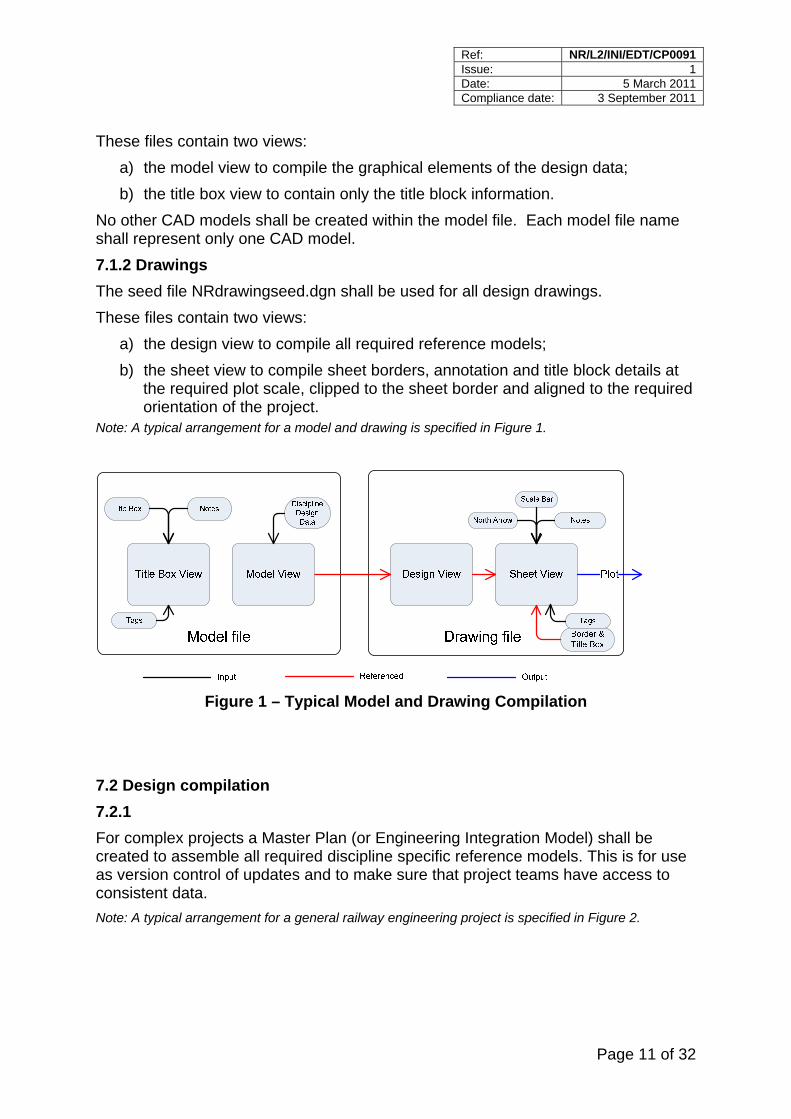
These files contain two views: a) the model view to compile the graphical elements of the design data; b) the title box view to contain only the title block information.
No other CAD models shall be created within the model file. Each model file name shall represent only one CAD model. 7.1.2 Drawings The seed file NRdrawingseed.dgn shall be used for all design drawings. These files contain two views:
a) the design view to compile all required reference models; b) the sheet view to compile sheet borders, annotation and title block details at
the required plot scale, clipped to the sheet border and aligned to the required orientation of the project.
Note: A typical arrangement for a model and drawing is specified in Figure 1.
Figure 1 – Typical Model and Drawing Compilation
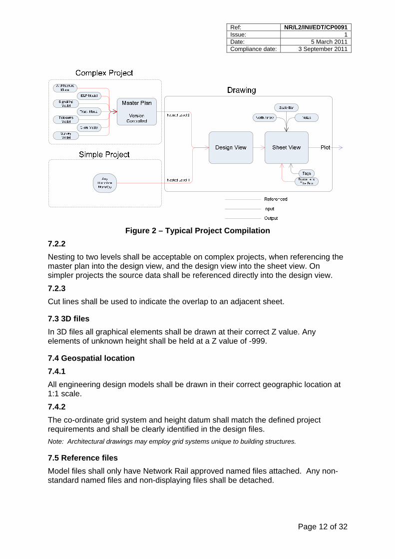
7.2 Design compilation 7.2.1 For complex projects a Master Plan (or Engineering Integration Model) shall be created to assemble all required discipline specific reference models. This is for use as version control of updates and to make sure that project teams have access to consistent data. Note: A typical arrangement for a general railway engineering project is specified in Figure 2.
Ref: NR/L2/INI/EDT/CP0091 Issue: 1 Date: 5 March 2011 Compliance date: 3 September 2011
Page 12 of 32
Figure 2 – Typical Project Compilation
7.2.2 Nesting to two levels shall be acceptable on complex projects, when referencing the master plan into the design view, and the design view into the sheet view. On simpler projects the source data shall be referenced directly into the design view. 7.2.3 Cut lines shall be used to indicate the overlap to an adjacent sheet.
7.3 3D files In 3D files all graphical elements shall be drawn at their correct Z value. Any elements of unknown height shall be held at a Z value of -999.
7.4 Geospatial location 7.4.1 All engineering design models shall be drawn in their correct geographic location at 1:1 scale. 7.4.2 The co-ordinate grid system and height datum shall match the defined project requirements and shall be clearly identified in the design files. Note: Architectural drawings may employ grid systems unique to building structures.
7.5 Reference files Model files shall only have Network Rail approved named files attached. Any non-standard named files and non-displaying files shall be detached.
Ref: NR/L2/INI/EDT/CP0091 Issue: 1 Date: 5 March 2011 Compliance date: 3 September 2011
Page 13 of 32
7.6 Plans and Sections Separate 3D model files shall be used for plans and sections, and shall be geospatially correct in the xyz plane.
8 Style and presentation
8.1 Title blocks The title box view in model files and the title block in the border files shall be populated using the supplied tag cells. 8.1.1 All drawings shall use the standard Network Rail title block and borders supplied in the supporting files. 8.1.2 The content and arrangement of the chosen title block shall remain unchanged, although it may be extended, by approval of the CAD Representative, with additional fields if required. All required information for the tags in the title block cells shall be completed in full. 8.1.3 Subsequent revisions of a drawing shall be itemised in the revision history box with a brief description of the update and initials only in the drawn, checked and approved area. The full revision history shall be kept at each drawing revision unless space restrictions require it to be reduced.
8.2 Scales 8.2.1 Drawings other than schematic diagrams shall be compiled in the model view at full size i.e. 1:1 scale. 8.2.2 The sheet view at A1, A2 etc shall be used for plotting the final drawing at the required scale within the referenced border file. 8.2.3 Scale bars shall be displayed on all plans and map based drawings with the appropriate written scale displayed in the title block. 8.2.4 Where more than one scale is used on a drawing, the scale for each view shall be shown.
Ref: NR/L2/INI/EDT/CP0091 Issue: 1 Date: 5 March 2011 Compliance date: 3 September 2011
Page 14 of 32
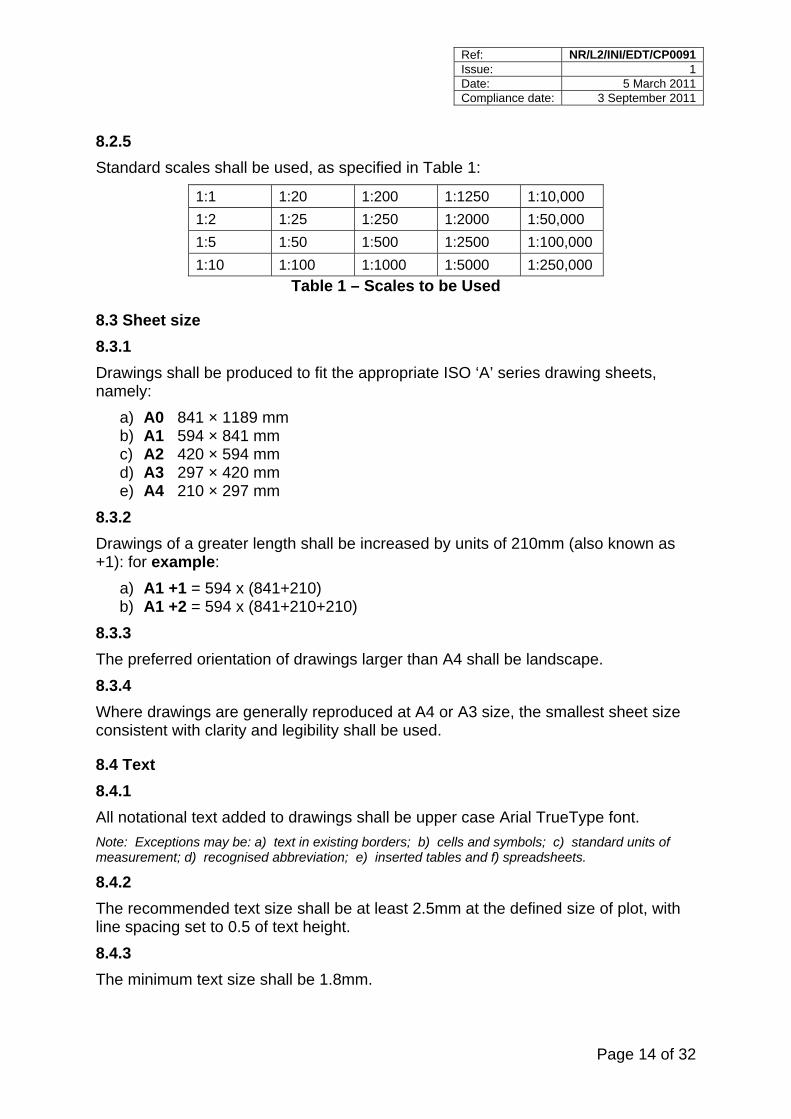
8.2.5 Standard scales shall be used, as specified in Table 1:
1:1 1:20 1:200 1:1250 1:10,000 1:2 1:25 1:250 1:2000 1:50,000 1:5 1:50 1:500 1:2500 1:100,000 1:10 1:100 1:1000 1:5000 1:250,000
Table 1 – Scales to be Used
8.3 Sheet size 8.3.1 Drawings shall be produced to fit the appropriate ISO ‘A’ series drawing sheets, namely:
a) A0 841 × 1189 mm b) A1 594 × 841 mm c) A2 420 × 594 mm d) A3 297 × 420 mm e) A4 210 × 297 mm
8.3.2 Drawings of a greater length shall be increased by units of 210mm (also known as +1): for example:
a) A1 +1 = 594 x (841+210) b) A1 +2 = 594 x (841+210+210)
8.3.3 The preferred orientation of drawings larger than A4 shall be landscape. 8.3.4 Where drawings are generally reproduced at A4 or A3 size, the smallest sheet size consistent with clarity and legibility shall be used.
8.4 Text 8.4.1 All notational text added to drawings shall be upper case Arial TrueType font. Note: Exceptions may be: a) text in existing borders; b) cells and symbols; c) standard units of measurement; d) recognised abbreviation; e) inserted tables and f) spreadsheets.
8.4.2 The recommended text size shall be at least 2.5mm at the defined size of plot, with line spacing set to 0.5 of text height. 8.4.3 The minimum text size shall be 1.8mm.
Ref: NR/L2/INI/EDT/CP0091 Issue: 1 Date: 5 March 2011 Compliance date: 3 September 2011
Page 15 of 32
8.4.4 Text shall be legible when reducing from A1 to A3. 8.4.5 Text sizes used for tags in the title block shall be set by the tags themselves. 8.4.6 Arial is a filled font; line weight shall be set to 0. 8.4.7 Text on drawings shall be clear, consistent and unambiguous and checked for spelling correctness. Note: Abbreviations should be kept to a minimum and clearly explained in a legend.
8.5 Cells 8.5.1 All drawings shall use the cell libraries supplied in the supporting files. Shared cells shall not be used. 8.5.2 New cells shall be created using a scale appropriate to the drawing content, using the ‘default’ level. Note: Additional cells should be created using the process specified in 6.2.2.
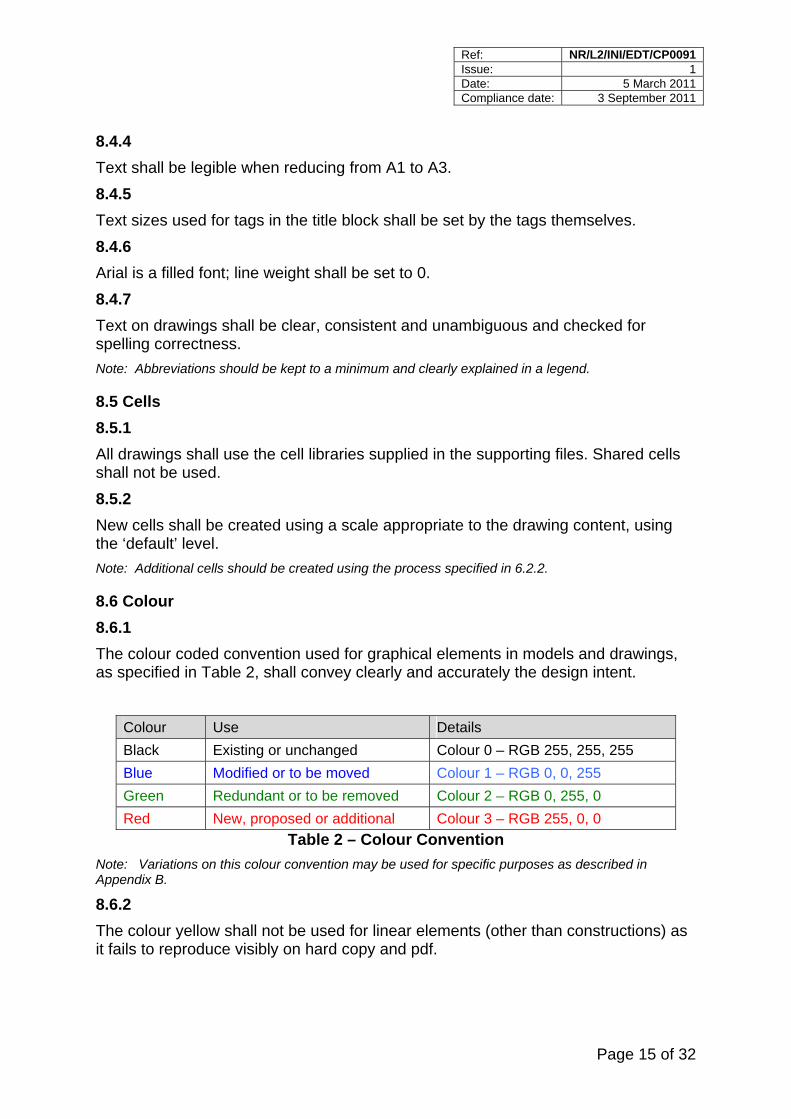
8.6 Colour 8.6.1 The colour coded convention used for graphical elements in models and drawings, as specified in Table 2, shall convey clearly and accurately the design intent.
Colour Use Details Black Existing or unchanged Colour 0 – RGB 255, 255, 255 Blue Modified or to be moved Colour 1 – RGB 0, 0, 255 Green Redundant or to be removed Colour 2 – RGB 0, 255, 0 Red New, proposed or additional Colour 3 – RGB 255, 0, 0
Table 2 – Colour Convention Note: Variations on this colour convention may be used for specific purposes as described in Appendix B.
8.6.2 The colour yellow shall not be used for linear elements (other than constructions) as it fails to reproduce visibly on hard copy and pdf.
Ref: NR/L2/INI/EDT/CP0091 Issue: 1 Date: 5 March 2011 Compliance date: 3 September 2011
Page 16 of 32
8.6.3 The supporting files contain colour tables for printing in colour. The standard MicroStation colour table, with the addition of the official RGB colours, shall be used for the Network Rail logo. These are:
Blue: R0, G81, B114 Red: R206, G38, B46
8.6.4 The Network Rail logo is a unique piece of artwork, a distinctive brand which shall be reproduced precisely on all CAD drawings. Note 1: Further details can be found at http://brand.networkrail.co.uk
Note 2: Two versions are supplied for CAD drawings, two colour and black only.
8.7 Line styles 8.7.1 All drawings shall use standard MicroStation line styles; custom line styles may be created as required, but the line style resources file shall be submitted as a deliverable. 8.7.2 To maintain clarity, an explanation of line styles shall be added to the drawing legend where necessary.
8.8 Dimensions 8.8.1 All dimensions shall be in accordance with the levels structure, as specified in Clause 9 and shall be consistent in style, colour and size. 8.8.2 All dimensions shall be in metric units using 3 decimal places for metres and whole numbers for millimetres. 8.8.3 Dimension lines shall not cross other dimension lines. Wherever possible, dimension lines shall not be broken. 8.8.4 Dimension witness lines shall begin slightly offset from the point to which they refer. 8.8.5 Dimension lines shall be terminated with filled arrowheads. 8.8.6 All drawings shall use the standard Microstation dimension styles.
Ref: NR/L2/INI/EDT/CP0091 Issue: 1 Date: 5 March 2011 Compliance date: 3 September 2011
Page 17 of 32
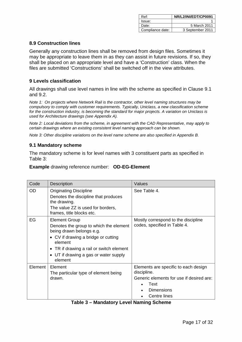
8.9 Construction lines Generally any construction lines shall be removed from design files. Sometimes it may be appropriate to leave them in as they can assist in future revisions. If so, they shall be placed on an appropriate level and have a ‘Construction’ class. When the files are submitted ‘Constructions’ shall be switched off in the view attributes.
9 Levels classification All drawings shall use level names in line with the scheme as specified in Clause 9.1 and 9.2. Note 1: On projects where Network Rail is the contractor, other level naming structures may be compulsory to comply with customer requirements. Typically, Uniclass, a new classification scheme for the construction industry, is becoming the standard for major projects. A variation on Uniclass is used for Architecture drawings (see Appendix A).
Note 2: Local deviations from the scheme, in agreement with the CAD Representative, may apply to certain drawings where an existing consistent level naming approach can be shown.
Note 3: Other discipline variations on the level name scheme are also specified in Appendix B.
9.1 Mandatory scheme The mandatory scheme is for level names with 3 constituent parts as specified in Table 3: Example drawing reference number: OD-EG-Element
Code Description Values OD Originating Discipline
Denotes the discipline that produces the drawing. The value ZZ is used for borders, frames, title blocks etc.
See Table 4.
EG Element Group Denotes the group to which the element being drawn belongs e.g. • CV if drawing a bridge or cutting
element • TR if drawing a rail or switch element • UT if drawing a gas or water supply
element
Mostly correspond to the discipline codes, specified in Table 4.
Element Element The particular type of element being drawn.
Elements are specific to each design discipline. Generic elements for use if desired are:
• Text • Dimensions • Centre lines
Table 3 – Mandatory Level Naming Scheme
Ref: NR/L2/INI/EDT/CP0091 Issue: 1 Date: 5 March 2011 Compliance date: 3 September 2011
Page 18 of 32
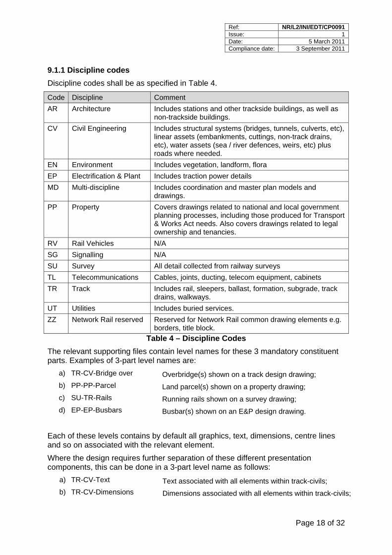
9.1.1 Discipline codes Discipline codes shall be as specified in Table 4.
Code Discipline Comment AR Architecture Includes stations and other trackside buildings, as well as
non-trackside buildings. CV Civil Engineering Includes structural systems (bridges, tunnels, culverts, etc),
linear assets (embankments, cuttings, non-track drains, etc), water assets (sea / river defences, weirs, etc) plus roads where needed.
EN Environment Includes vegetation, landform, flora EP Electrification & Plant Includes traction power details MD Multi-discipline Includes coordination and master plan models and
drawings. PP Property Covers drawings related to national and local government
planning processes, including those produced for Transport & Works Act needs. Also covers drawings related to legal ownership and tenancies.
RV Rail Vehicles N/A SG Signalling N/A SU Survey All detail collected from railway surveys TL Telecommunications Cables, joints, ducting, telecom equipment, cabinets TR Track Includes rail, sleepers, ballast, formation, subgrade, track
drains, walkways. UT Utilities Includes buried services. ZZ Network Rail reserved Reserved for Network Rail common drawing elements e.g.
borders, title block. Table 4 – Discipline Codes
The relevant supporting files contain level names for these 3 mandatory constituent parts. Examples of 3-part level names are:
a) TR-CV-Bridge over Overbridge(s) shown on a track design drawing; b) PP-PP-Parcel Land parcel(s) shown on a property drawing; c) SU-TR-Rails Running rails shown on a survey drawing; d) EP-EP-Busbars Busbar(s) shown on an E&P design drawing.
Each of these levels contains by default all graphics, text, dimensions, centre lines and so on associated with the relevant element. Where the design requires further separation of these different presentation components, this can be done in a 3-part level name as follows:
a) TR-CV-Text Text associated with all elements within track-civils; b) TR-CV-Dimensions Dimensions associated with all elements within track-civils;
Ref: NR/L2/INI/EDT/CP0091 Issue: 1 Date: 5 March 2011 Compliance date: 3 September 2011
Page 19 of 32
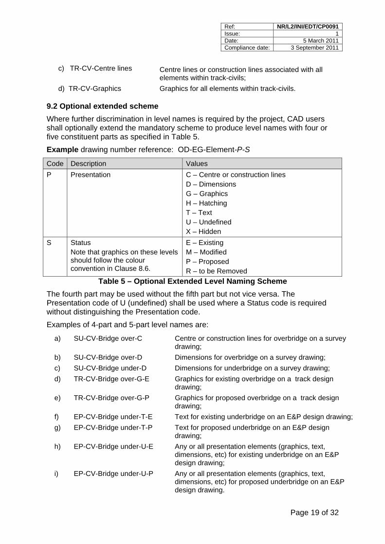
c) TR-CV-Centre lines Centre lines or construction lines associated with all elements within track-civils;
d) TR-CV-Graphics Graphics for all elements within track-civils.
9.2 Optional extended scheme Where further discrimination in level names is required by the project, CAD users shall optionally extend the mandatory scheme to produce level names with four or five constituent parts as specified in Table 5. Example drawing number reference: OD-EG-Element-P-S
Code Description Values P Presentation C – Centre or construction lines
D – Dimensions G – Graphics H – Hatching T – Text U – Undefined X – Hidden
S Status Note that graphics on these levels should follow the colour convention in Clause 8.6.
E – Existing M – Modified P – Proposed R – to be Removed
Table 5 – Optional Extended Level Naming Scheme The fourth part may be used without the fifth part but not vice versa. The Presentation code of U (undefined) shall be used where a Status code is required without distinguishing the Presentation code. Examples of 4-part and 5-part level names are:
a) SU-CV-Bridge over-C Centre or construction lines for overbridge on a survey drawing;
b) SU-CV-Bridge over-D Dimensions for overbridge on a survey drawing; c) SU-CV-Bridge under-D Dimensions for underbridge on a survey drawing; d) TR-CV-Bridge over-G-E Graphics for existing overbridge on a track design
drawing; e) TR-CV-Bridge over-G-P Graphics for proposed overbridge on a track design
drawing; f) EP-CV-Bridge under-T-E Text for existing underbridge on an E&P design drawing; g) EP-CV-Bridge under-T-P Text for proposed underbridge on an E&P design
drawing; h) EP-CV-Bridge under-U-E Any or all presentation elements (graphics, text,
dimensions, etc) for existing underbridge on an E&P design drawing;
i) EP-CV-Bridge under-U-P Any or all presentation elements (graphics, text, dimensions, etc) for proposed underbridge on an E&P design drawing.
Ref: NR/L2/INI/EDT/CP0091 Issue: 1 Date: 5 March 2011 Compliance date: 3 September 2011
Page 20 of 32
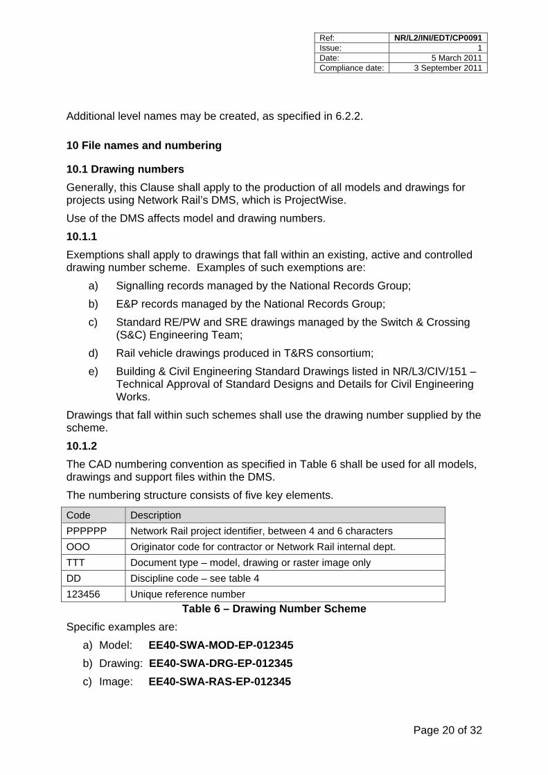
Additional level names may be created, as specified in 6.2.2.
10 File names and numbering
10.1 Drawing numbers Generally, this Clause shall apply to the production of all models and drawings for projects using Network Rail’s DMS, which is ProjectWise. Use of the DMS affects model and drawing numbers. 10.1.1 Exemptions shall apply to drawings that fall within an existing, active and controlled drawing number scheme. Examples of such exemptions are:
a) Signalling records managed by the National Records Group; b) E&P records managed by the National Records Group; c) Standard RE/PW and SRE drawings managed by the Switch & Crossing
(S&C) Engineering Team; d) Rail vehicle drawings produced in T&RS consortium; e) Building & Civil Engineering Standard Drawings listed in NR/L3/CIV/151 –
Technical Approval of Standard Designs and Details for Civil Engineering Works.
Drawings that fall within such schemes shall use the drawing number supplied by the scheme. 10.1.2 The CAD numbering convention as specified in Table 6 shall be used for all models, drawings and support files within the DMS. The numbering structure consists of five key elements.
Code Description PPPPPP Network Rail project identifier, between 4 and 6 characters OOO Originator code for contractor or Network Rail internal dept. TTT Document type – model, drawing or raster image only DD Discipline code – see table 4 123456 Unique reference number
Table 6 – Drawing Number Scheme Specific examples are:
a) Model: EE40-SWA-MOD-EP-012345 b) Drawing: EE40-SWA-DRG-EP-012345 c) Image: EE40-SWA-RAS-EP-012345
Ref: NR/L2/INI/EDT/CP0091 Issue: 1 Date: 5 March 2011 Compliance date: 3 September 2011
Page 21 of 32
In cases where a project decides it can benefit from discriminating different sites or locations within the project, a 3 letter location code field may be added to reflect project specific locations. This may be shown for example as: EE40-SWA-DRG-EP-MDN-012345
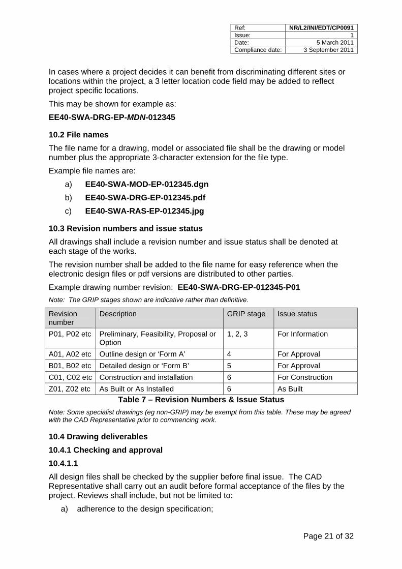
10.2 File names The file name for a drawing, model or associated file shall be the drawing or model number plus the appropriate 3-character extension for the file type. Example file names are:
a) EE40-SWA-MOD-EP-012345.dgn b) EE40-SWA-DRG-EP-012345.pdf c) EE40-SWA-RAS-EP-012345.jpg
10.3 Revision numbers and issue status All drawings shall include a revision number and issue status shall be denoted at each stage of the works. The revision number shall be added to the file name for easy reference when the electronic design files or pdf versions are distributed to other parties. Example drawing number revision: EE40-SWA-DRG-EP-012345-P01 Note: The GRIP stages shown are indicative rather than definitive.
Revision number
Description GRIP stage Issue status
P01, P02 etc Preliminary, Feasibility, Proposal or Option
1, 2, 3 For Information
A01, A02 etc Outline design or ‘Form A’ 4 For Approval B01, B02 etc Detailed design or ‘Form B’ 5 For Approval C01, C02 etc Construction and installation 6 For Construction Z01, Z02 etc As Built or As Installed 6 As Built
Table 7 – Revision Numbers & Issue Status Note: Some specialist drawings (eg non-GRIP) may be exempt from this table. These may be agreed with the CAD Representative prior to commencing work.
10.4 Drawing deliverables 10.4.1 Checking and approval 10.4.1.1 All design files shall be checked by the supplier before final issue. The CAD Representative shall carry out an audit before formal acceptance of the files by the project. Reviews shall include, but not be limited to:
a) adherence to the design specification;
Ref: NR/L2/INI/EDT/CP0091 Issue: 1 Date: 5 March 2011 Compliance date: 3 September 2011
Page 22 of 32
b) compliance with specified standards; c) neatness and clarity of text and graphics; d) consistency of style; e) dimensional accuracy; f) correct references to other drawings or documents; g) information missing from the check print due to plotter malfunction.
10.4.1.2 Files shall be purged so that graphics on non-plotting levels, unused levels and non-displaying reference files are removed. No graphics shall appear outside of the drawing border. 10.4.1.3 Standard practice is for approved hard copy drawings to be signed with ‘wet ink’ signatures. Where applicable projects shall make specific arrangements with Network Rail to accept electronic signatures in place of wet ink signatures. 10.4.2 Projects using Network Rail’s DMS For projects using Network Rail’s DMS, submissions shall be made in line with the defined procedures for ProjectWise. 10.4.3 Projects not using Network Rail’s DMS 10.4.3.1 For projects NOT using Network Rail’s DMS, CAD data submitted to Network Rail at agreed milestones shall be:
a) hard copy printed from each original drawing file, signed and approved (number of copies to be specified by the project);
b) PDF file for each drawing. This may or may not be a scanned copy of the signed hard copy as determined by the project;
c) EITHER of the following as determined by the project: 1. each CAD drawing file compressed as a bound file with all reference
files merged; 2. all source model files, drawing files and component reference files.
The use of MicroStation’s Packager utility is recommended to allow a complete project to be more easily re-assembled on another CAD workstation. 10.4.3.2 CAD data shall be submitted under cover of a transmittal. Transmittals shall include:
a) the medium for delivery as determined by the project;
Ref: NR/L2/INI/EDT/CP0091 Issue: 1 Date: 5 March 2011 Compliance date: 3 September 2011
Page 23 of 32
b) each transmittal accompanied by a transmittal form containing, as a minimum, the following information:
1. Transmittal header details - unique transmittal number, project name, contract number, issue date, supplier name and address, supplier contact name, intended recipient name and address, receipt acknowledgement section.
2. Details for each CAD drawing or model - drawing number, drawing title, revision number, issue status, delivery medium or media, number of copies.
c) Where necessary, a ‘Readme’ file explaining the CAD file project structure.
11 Intellectual property Ownership and usage of CAD data and drawings produced by a project shall be governed by the project contract.
12 Ordnance Survey data
12.1 Service agreement Network Rail operates a service level agreement with Ordnance Survey for a range of digital products, which shall be supplied under licence to contractors working on any of its projects. Requests for data shall be made in the first instance to the CAD Representative. Note 1: Products include:
a) MasterMap GIS data containing topography, address, transport and aerial imagery layers;
b) Landform Profile 1:10,000 digital height data for terrain modelling;
c) 1:50,000 colour raster small scale mapping.
Note 2: A number of other products are freely available under the Opendata initiative, for further information refer to: http://www.ordnancesurvey.co.uk
12.1.1 All products are referenced to OSGB36 National Grid. Where projects are set up using recognised railway co-ordinate systems e.g. London Survey Grid, or where survey data has been collected using a local grid, then transformation parameters shall be supplied by the originator to translate the OS data to and from the correct geographical reference. 12.1.2 All drawings that incorporate OS map data shall display the following copyright note:
OS map data reproduced by permission of Ordnance Survey on behalf of HMSO. © Crown copyright [year]. All rights reserved. Ordnance Survey licence number 0100040692.
Ref: NR/L2/INI/EDT/CP0091 Issue: 1 Date: 5 March 2011 Compliance date: 3 September 2011
Page 24 of 32
12.1.3 Where there is insufficient space to allow the full acknowledgement, an abbreviated version shall be used:
© Crown copyright [year]. All rights reserved. Ordnance Survey licence number 0100040692.
Ref: NR/L2/INI/EDT/CP0091 Issue: 1 Date: 5 March 2011 Compliance date: 3 September 2011
Page 25 of 32
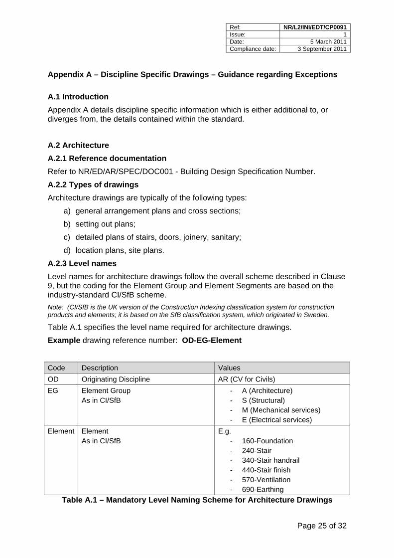
Appendix A – Discipline Specific Drawings – Guidance regarding Exceptions A.1 Introduction Appendix A details discipline specific information which is either additional to, or diverges from, the details contained within the standard. A.2 Architecture A.2.1 Reference documentation Refer to NR/ED/AR/SPEC/DOC001 - Building Design Specification Number. A.2.2 Types of drawings Architecture drawings are typically of the following types:
a) general arrangement plans and cross sections; b) setting out plans; c) detailed plans of stairs, doors, joinery, sanitary; d) location plans, site plans.
A.2.3 Level names Level names for architecture drawings follow the overall scheme described in Clause 9, but the coding for the Element Group and Element Segments are based on the industry-standard CI/SfB scheme. Note: (CI/SfB is the UK version of the Construction Indexing classification system for construction products and elements; it is based on the SfB classification system, which originated in Sweden.
Table A.1 specifies the level name required for architecture drawings. Example drawing reference number: OD-EG-Element
Code Description Values OD Originating Discipline AR (CV for Civils) EG Element Group
As in CI/SfB - A (Architecture) - S (Structural) - M (Mechanical services) - E (Electrical services)
Element Element As in CI/SfB
E.g. - 160-Foundation - 240-Stair - 340-Stair handrail - 440-Stair finish - 570-Ventilation - 690-Earthing
Table A.1 – Mandatory Level Naming Scheme for Architecture Drawings
Ref: NR/L2/INI/EDT/CP0091 Issue: 1 Date: 5 March 2011 Compliance date: 3 September 2011
Page 26 of 32
Example level names are: a) AR-S-160-Foundation; b) AR-A-240-Stair; c) AR-E-690-Earthing.
In cases where the optional extended four-part or five-part level naming scheme is used, information regarding the requirements for the fourth and fifth parts (Presentation and Status) are specified in Clause 9. A.3 Civil Engineering A.3.1 Reference documentation Refer to:
a) NR/SP/CIV/003 – Technical Approval of Design, Construction and Maintenance of Civil Engineering Infrastructure;
b) NR/L3/CIV/151 – Technical Approval of Standard Designs and Details for Civil Engineering Works.
A.3.2 Types of drawings Civil Engineering drawings are typically of the following types:
a) Survey data models and associated drawings; b) Permanent works drawings – outline design and detailed design; c) Temporary works design drawings; d) As built record drawings; e) Network Rail Civil Engineering Standard Design and Details drawings (e.g.
NR/CIV/SD/series). A.3.3 Level Names Level naming is based on a similar structure to Architecture as at A.2.3, but using CV as the originating discipline. A.4 Electrification and Plant (E&P) Note: Examples of “special cases” are Overhead Line and Conductor Rail. In such cases compliance is required with NRG standards.
A.4.1 Reference documentation Refer to:
a) NR/L2/ELP/21120 – E&P Records Management Process; b) NR/GN/ELP/27309 – DC Electric Track Equipment Drawing Index; c) NR/SP/ELP/27221 – Overhead Line Equipment Master Index; d) NR/GN/27246 – Data Held in the Overhead Line Master Index;
Ref: NR/L2/INI/EDT/CP0091 Issue: 1 Date: 5 March 2011 Compliance date: 3 September 2011
Page 27 of 32
e) NR/L2/ELP/27311 – Technical Approval of Electrification and Plant Asset Design;
f) NR/SP/ELP/21104 – Design & Installation of Electric Track Equipment for DC Electrified Lines (formerly RT/E/S/21104);
g) NR/SP/ELP/27300 – Specification for Computer Aided Design Formats for Electrification and Plant Documentation
A.4.2 Types of drawings E&P drawings are typically of the following types:
a) comprehensive track diagrams, major feeding diagrams, single line diagrams, isolation diagrams and operational diagrams;
b) electrical schematics, wiring diagrams, circuit diagrams and HV cable route diagrams;
c) conductor rail drawings, negative bonding drawings and points heating layouts;
d) substation diagrams, site location, access plans and layout drawings; e) hydraulic and alarm system diagrams and pilot boxes; f) arrangement of track circuits, negative bonding drawings and troughing
layouts; g) outstation installation diagrams and trackside location diagrams; h) SCADA drawings; i) OLE basic design drawings, including standard arrangements, technical
sheets, assemblies, sub assemblies and components and materials allocation drawings;
j) ETE drawings for third rail electrification standard arrangements, assemblies and components;
k) equipment layout drawings. A.5 Rail vehicles A.5.1 Reference documentation Refer to RT/CES/3/01315 – Chief Engineer’s Specification: Format and Standards of Network Rail Rail Vehicle Engineering Drawings. A.5.2 Drawing numbers Rail vehicle drawing numbers are assigned using a scheme administered by the T&RS Consortium.
Ref: NR/L2/INI/EDT/CP0091 Issue: 1 Date: 5 March 2011 Compliance date: 3 September 2011
Page 28 of 32
A.5.3 Software Rail vehicle design involving Network Rail is often performed using the Solid Edge CAD system. The use of Solid Edge CAD system is practically applied throughout this standard, although no supporting files are provided for this system. A.6 Signalling A.6.1 Reference documentation Note: Existing signalling procedures specify a range of CAD related practices, which take precedence over the requirements of this specification. Significant differences are detailed in this section.
Refer to: a) NR/GN/SIG/11701 - Signalling Design: Production Guidance; b) NR/SP/SIG/11201 - Signalling Design: Production; c) RT/E/C/11004 - Symbols for use on Signalling Plans and Sketches; d) NR/GN/SIG/11205 - Symbols for Signalling Circuit Diagrams; e) NR/L3/SIG/30018 - Signalling Design: Technical Details – Level Crossings f) NR/L2/SIG/30004 - CAD Cell Library; g) NR/L2/INF/02018 – Specification for the Management of Safety Related
Infrastructure Records.
A.6.2 Types of drawings Signalling drawings are typically of the following types:
a) signalling layout plans, route list and aspect sequence charts; b) signal sighting forms; c) location area plans, cable route plans and air main details; d) track circuit bonding plans*; e) level crossing ground plans; f) control tables; g) power and lineside cable plans and detailed core plans; h) mechanical locking charts and lever frame details; i) signal box and interlocking circuit diagrams, schematics and equipment
details; j) lineside location circuit diagrams, schematics and equipment details; k) electronic systems details; l) signalling control and display system details, isolation overlays and signallers
route cards.
Ref: NR/L2/INI/EDT/CP0091 Issue: 1 Date: 5 March 2011 Compliance date: 3 September 2011
Page 29 of 32
* Track circuit bonding plans applicable to areas containing OLE are to include OLE bonding arrangements. These plans are owned by the signalling engineer and approved by both the signalling engineer and the Electrification & Plant Design Group.
A.6.3 Level names Generally the display levels used on signalling drawings are set by the customised software used. A.6.4 Fonts A modified version of Font 50 is used as standard for circuit drawings and related schematics. Font 1 is used for signalling layout and location area plans. A.6.5 Drawing numbers With the exception of signalling scheme plans all signalling source records are controlled by the National Records Group. The drawing numbering is dependent upon the geographical area of work; there is a mandatory requirement that the numbering structure is maintained when new drawings are produced or existing drawings amended. Details are available from the appropriate records custodian. Signalling scheme plan numbers are issued on a project by project basis by the appropriate Signal Engineering Design Manager. Signalling records require an alpha numeric system for version control. The National Records Group manage the issue of versions in accordance with Signalling Design: Production (NR/SP/SIG/11201). A.7 Survey A.7.1 Reference documentation Refer to NR/EE/SPE/0065 – Generic Programme Specification (Clause 3.3.1 Survey and Mapping). A.7.2 Types of drawings Survey drawings are typically of the following types:
a) survey data models; b) survey control network plans; c) control station witness diagrams; d) ground marker location plans; e) aerial photography index plans; f) photomosaic layout plans; g) Ordnance Survey plans.
Ref: NR/L2/INI/EDT/CP0091 Issue: 1 Date: 5 March 2011 Compliance date: 3 September 2011
Page 30 of 32
A.8 Telecommunications A.8.1 Reference documentation Refer to:
a) A305\GSM-R\P\154 - GSM-R Base Station Site Elements; b) A305\GSM-R\IMP\P-042 - GSM-R Asset Data Management Procedure; c) SP/FTN(D&D)/017 - FTN Specification for Asbuilt Records for Cables and
Cable Routes; d) SP/FTN/(D&D)/016 - FTN Specification for Identification and Labelling of
Network Elements A.8.2 Types of drawings Telecoms drawings are typically of the following types:
a) SLD (Straight line diagrams); b) FSD (Fibre splice diagrams); c) site general arrangement drawings; d) site special condition drawings; e) site electrical & earth layout drawings; f) transmission design drawings; g) floor plan layout drawings; h) tower and fixing detailed drawings; i) tower base detail drawings; j) equipment housing layout drawings; k) electrical schematic drawings; l) joint enclosure drawings; m) standard detail drawings; n) building drawings; o) cab layout drawings; p) mapping drawings; q) detail drawings.
A.9 Track A.9.1 Reference documentation Refer to:
a) NR/L2/TRK/2049 - Track Design Handbook;
Ref: NR/L2/INI/EDT/CP0091 Issue: 1 Date: 5 March 2011 Compliance date: 3 September 2011
Page 31 of 32
b) NR/L2/TRK/2500 - Technical Approval in the Design of Track Infrastructure; c) NR/L2/TRK/7004 - Permanent Way Standard Drawings (RE/PW Series).
A.9.2 Types of drawings Track engineering drawings are typically of the following types:
a) Network Rail Track Engineering Standard Drawings (RE/PW and SRE series) including: general arrangement drawings of switches, crossings, turnouts, crossovers, double junctions. Plus component, assembly and manufacturing drawings;
b) through alignment design; c) drainage drawings;
d) longitudinal sections; e) site specific switch and crossing layouts
A.9.3 Colour For designs involving multiple tracks, the standard colour convention may not adequately distinguish between the tracks. In such cases an appropriate alternative colour convention, agreed in advance with the Network Rail project manager, may be used. A.9.4 Drawing numbers RE/PW and SRE standard drawings are controlled by the Principal Engineer (S&C). The drawing numbering system is dependent upon the nature of the S&C or component portrayed; there is a mandatory requirement that the numbering structure is maintained when new drawings are produced or existing drawings amended by projects. Details are available from the Track Drawings Engineer.
Ref: NR/L2/INI/EDT/CP0091 Issue: 1 Date: 5 March 2011 Compliance date: 3 September 2011
Page 32 of 32
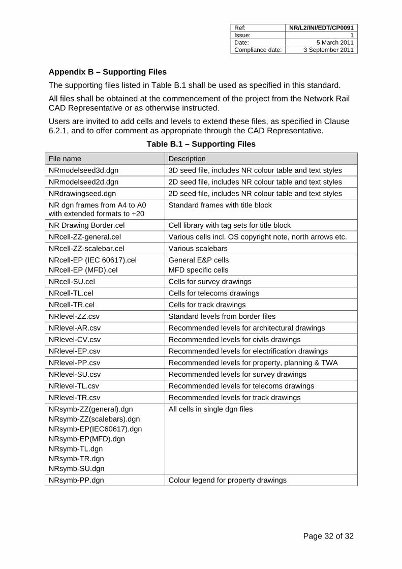
Appendix B – Supporting Files The supporting files listed in Table B.1 shall be used as specified in this standard. All files shall be obtained at the commencement of the project from the Network Rail CAD Representative or as otherwise instructed. Users are invited to add cells and levels to extend these files, as specified in Clause 6.2.1, and to offer comment as appropriate through the CAD Representative.
Table B.1 – Supporting Files
File name Description NRmodelseed3d.dgn 3D seed file, includes NR colour table and text styles NRmodelseed2d.dgn 2D seed file, includes NR colour table and text styles NRdrawingseed.dgn 2D seed file, includes NR colour table and text styles NR dgn frames from A4 to A0 with extended formats to +20
Standard frames with title block
NR Drawing Border.cel Cell library with tag sets for title block NRcell-ZZ-general.cel Various cells incl. OS copyright note, north arrows etc. NRcell-ZZ-scalebar.cel Various scalebars NRcell-EP (IEC 60617).cel NRcell-EP (MFD).cel
General E&P cells MFD specific cells
NRcell-SU.cel Cells for survey drawings NRcell-TL.cel Cells for telecoms drawings NRcell-TR.cel Cells for track drawings NRlevel-ZZ.csv Standard levels from border files NRlevel-AR.csv Recommended levels for architectural drawings NRlevel-CV.csv Recommended levels for civils drawings NRlevel-EP.csv Recommended levels for electrification drawings NRlevel-PP.csv Recommended levels for property, planning & TWA NRlevel-SU.csv Recommended levels for survey drawings NRlevel-TL.csv Recommended levels for telecoms drawings NRlevel-TR.csv Recommended levels for track drawings NRsymb-ZZ(general).dgn NRsymb-ZZ(scalebars).dgn NRsymb-EP(IEC60617).dgn NRsymb-EP(MFD).dgn NRsymb-TL.dgn NRsymb-TR.dgn NRsymb-SU.dgn
All cells in single dgn files
NRsymb-PP.dgn Colour legend for property drawings
Version 1
Page 1 of 5
Standards Briefing Note
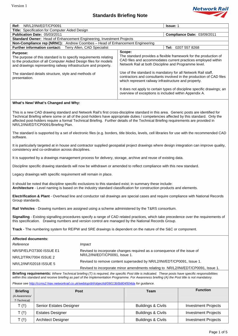
Ref: NR/L2/INI/EDT/CP0091 Issue: 1 Title: Specification for Computer Aided Design Publication Date: 05/03/2011 Compliance Date: 03/09/2011 Standard Owner: Head of Enhancement Engineering, Investment Projects Non-Compliance rep (NRNC): Andrew Coombes – Head of Enhancement Engineering Further information contact: Terry Allen, CAD Specialist Tel: 0207 557 8268 Purpose: The purpose of this standard is to specify requirements relating to the production of all Computer Aided Design files for models and drawings representing railway infrastructure and property. The standard details structure, style and methods of presentation.
Scope: The standard provides a flexible framework for the production of CAD files and accommodates current practices employed within Network Rail at both Discipline and Programme level. Use of the standard is mandatory for all Network Rail staff, contractors and consultants involved in the production of CAD files which represent railway infrastructure and property. It does not apply to certain types of discipline specific drawings; an overview of exceptions is included within Appendix A.
What’s New/ What’s Changed and Why: This is a new CAD drawing standard and Network Rail’s first cross-discipline standard in this area. Generic posts are identified for Technical Briefing where some or all of the post-holders have appropriate duties / competencies affected by this standard. Only the affected post-holders require a formal Technical Briefing. Further details of the Technical Briefing requirements are provided in NR/L2/INI/EDT/CP0091/Briefing Plan. The standard is supported by a set of electronic files (e.g. borders, title blocks, levels, cell libraries for use with the recommended CAD software. It is particularly targeted at in house and contractor supplied geospatial project drawings where design integration can improve quality, consistency and co-ordination across disciplines. It is supported by a drawings management process for delivery, storage, archive and reuse of existing data. Discipline specific drawing standards will now be withdrawn or amended to reflect compliance with this new standard. Legacy drawings with specific requirement will remain in place. It should be noted that discipline specific exclusions to this standard exist; in summary these include: Architecture - Level naming is based on the industry standard classification for construction products and elements. Electrification & Plant - Overhead line and conductor rail drawings are special cases and require compliance with National Records Group standards. Rail Vehicles - Drawing numbers are assigned using a scheme administered by the T&RS consortium. Signalling - Existing signalling procedures specify a range of CAD related practices, which take precedence over the requirements of this specification. Drawing numbers and version control are managed by the National Records Group. Track - The numbering system for RE/PW and SRE drawings is dependent on the nature of the S&C or component. Affected documents: Reference
NR/SP/ELP/27300 ISSUE E1
NR/L2/TRK/7004 ISSUE 2
NR/L2/INF/02018 ISSUE 5
Impact
Revised to incorporate changes required as a consequence of the issue of NR/L2/INI/EDT/CP0091, Issue 1.
Revised to remove content superseded by NR/L2/INI/EDT/CP0091, Issue 1.
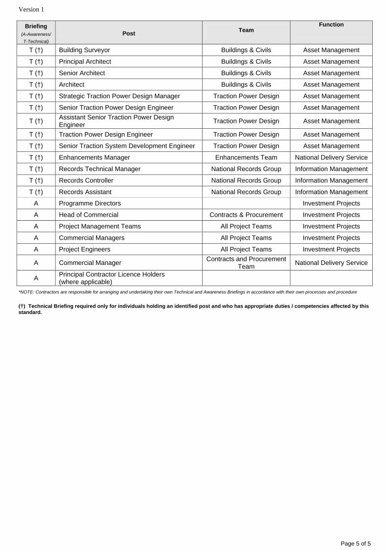
Revised to incorporate minor amendments relating to NR/L2/INI/EDT/CP0091, Issue 1. Briefing requirements: Where Technical briefing (T) is required, the specific Post title is indicated. These posts have specific responsibilities within this standard and receive briefing as part of the Implementation Programme. For Awareness briefing (A) the Post title is not mandatory.
Please see http://ccms2.hiav.networkrail.co.uk/webtop/drl/objectId/09013b5b804504da for guidance.
Briefing (A-Awareness/ T-Technical)
Post Team
Function
T (†) Senior Estates Designer Buildings & Civils Investment Projects
T (†) Estates Designer Buildings & Civils Investment Projects
T (†) Architect Designer Buildings & Civils Investment Projects
Version 1
Page 2 of 5
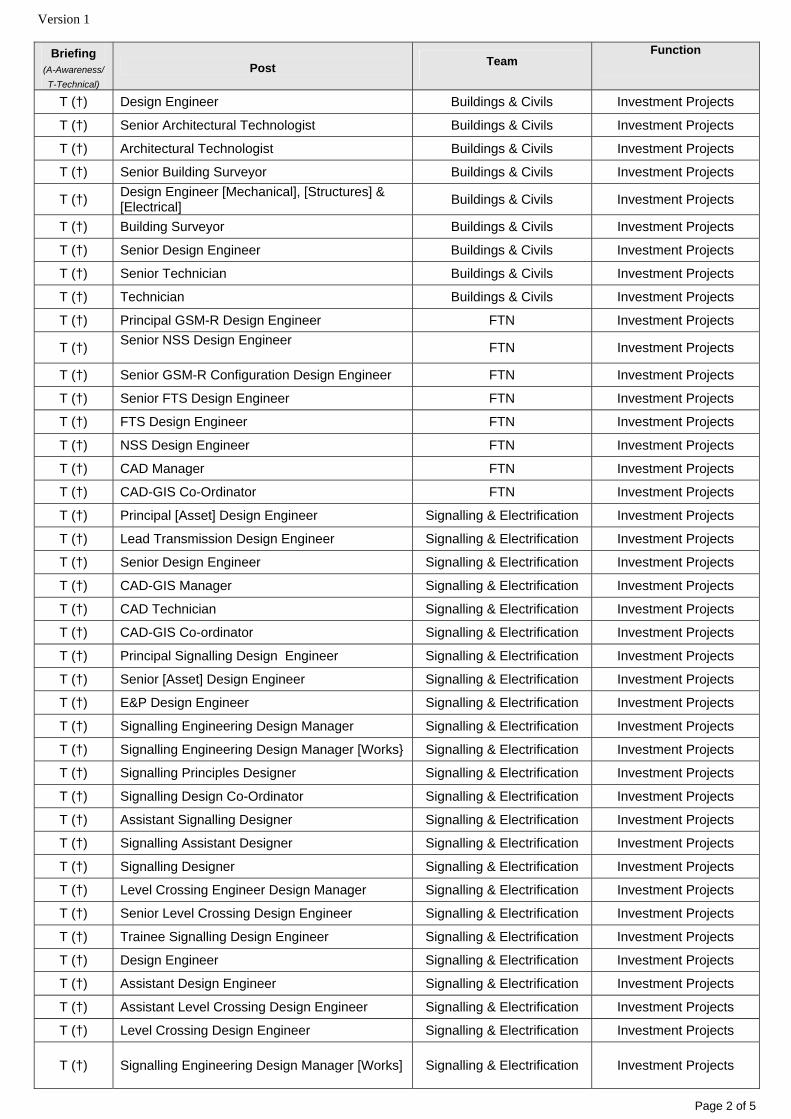
Briefing (A-Awareness/ T-Technical)
Post Team
Function
T (†) Design Engineer Buildings & Civils Investment Projects
T (†) Senior Architectural Technologist Buildings & Civils Investment Projects
T (†) Architectural Technologist Buildings & Civils Investment Projects
T (†) Senior Building Surveyor Buildings & Civils Investment Projects
T (†) Design Engineer [Mechanical], [Structures] & [Electrical] Buildings & Civils Investment Projects
T (†) Building Surveyor Buildings & Civils Investment Projects
T (†) Senior Design Engineer Buildings & Civils Investment Projects
T (†) Senior Technician Buildings & Civils Investment Projects
T (†) Technician Buildings & Civils Investment Projects
T (†) Principal GSM-R Design Engineer FTN Investment Projects
T (†) Senior NSS Design Engineer FTN Investment Projects
T (†) Senior GSM-R Configuration Design Engineer FTN Investment Projects
T (†) Senior FTS Design Engineer FTN Investment Projects
T (†) FTS Design Engineer FTN Investment Projects
T (†) NSS Design Engineer FTN Investment Projects
T (†) CAD Manager FTN Investment Projects
T (†) CAD-GIS Co-Ordinator FTN Investment Projects
T (†) Principal [Asset] Design Engineer Signalling & Electrification Investment Projects
T (†) Lead Transmission Design Engineer Signalling & Electrification Investment Projects
T (†) Senior Design Engineer Signalling & Electrification Investment Projects
T (†) CAD-GIS Manager Signalling & Electrification Investment Projects
T (†) CAD Technician Signalling & Electrification Investment Projects
T (†) CAD-GIS Co-ordinator Signalling & Electrification Investment Projects
T (†) Principal Signalling Design Engineer Signalling & Electrification Investment Projects
T (†) Senior [Asset] Design Engineer Signalling & Electrification Investment Projects
T (†) E&P Design Engineer Signalling & Electrification Investment Projects
T (†) Signalling Engineering Design Manager Signalling & Electrification Investment Projects
T (†) Signalling Engineering Design Manager [Works} Signalling & Electrification Investment Projects
T (†) Signalling Principles Designer Signalling & Electrification Investment Projects
T (†) Signalling Design Co-Ordinator Signalling & Electrification Investment Projects
T (†) Assistant Signalling Designer Signalling & Electrification Investment Projects
T (†) Signalling Assistant Designer Signalling & Electrification Investment Projects
T (†) Signalling Designer Signalling & Electrification Investment Projects
T (†) Level Crossing Engineer Design Manager Signalling & Electrification Investment Projects
T (†) Senior Level Crossing Design Engineer Signalling & Electrification Investment Projects
T (†) Trainee Signalling Design Engineer Signalling & Electrification Investment Projects
T (†) Design Engineer Signalling & Electrification Investment Projects
T (†) Assistant Design Engineer Signalling & Electrification Investment Projects
T (†) Assistant Level Crossing Design Engineer Signalling & Electrification Investment Projects
T (†) Level Crossing Design Engineer Signalling & Electrification Investment Projects
T (†) Signalling Engineering Design Manager [Works]
Signalling & Electrification Investment Projects
Version 1
Page 3 of 5
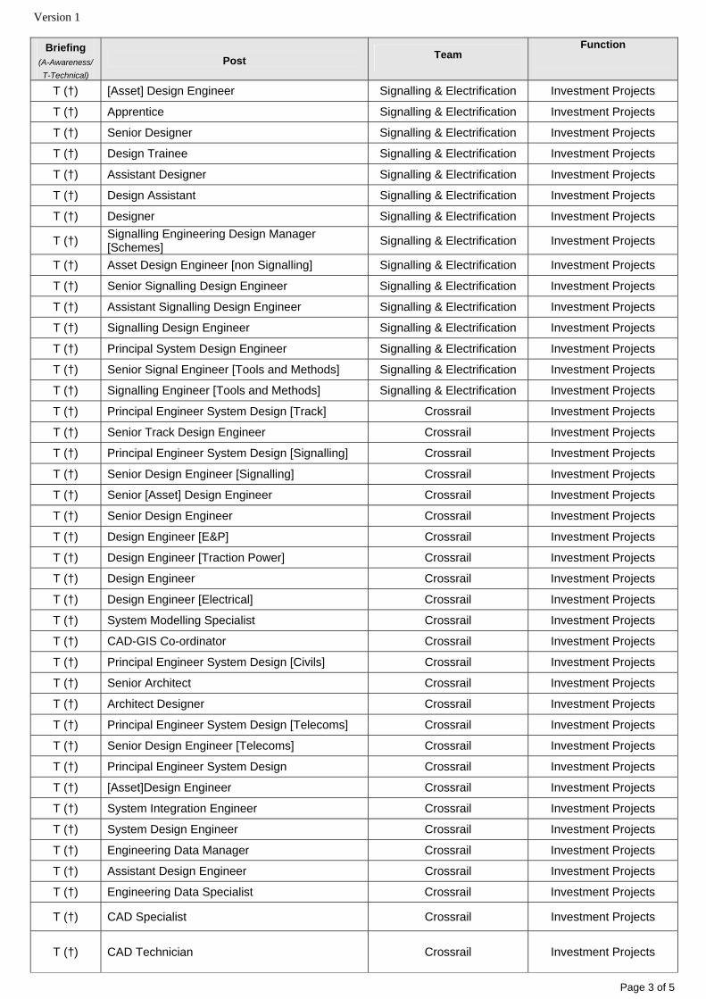
Briefing (A-Awareness/ T-Technical)
Post Team
Function
T (†) [Asset] Design Engineer Signalling & Electrification Investment Projects
T (†) Apprentice Signalling & Electrification Investment Projects
T (†) Senior Designer Signalling & Electrification Investment Projects
T (†) Design Trainee Signalling & Electrification Investment Projects
T (†) Assistant Designer Signalling & Electrification Investment Projects
T (†) Design Assistant Signalling & Electrification Investment Projects
T (†) Designer Signalling & Electrification Investment Projects
T (†) Signalling Engineering Design Manager [Schemes] Signalling & Electrification Investment Projects
T (†) Asset Design Engineer [non Signalling] Signalling & Electrification Investment Projects
T (†) Senior Signalling Design Engineer Signalling & Electrification Investment Projects
T (†) Assistant Signalling Design Engineer Signalling & Electrification Investment Projects
T (†) Signalling Design Engineer Signalling & Electrification Investment Projects
T (†) Principal System Design Engineer Signalling & Electrification Investment Projects
T (†) Senior Signal Engineer [Tools and Methods] Signalling & Electrification Investment Projects
T (†) Signalling Engineer [Tools and Methods] Signalling & Electrification Investment Projects
T (†) Principal Engineer System Design [Track] Crossrail Investment Projects
T (†) Senior Track Design Engineer Crossrail Investment Projects
T (†) Principal Engineer System Design [Signalling] Crossrail Investment Projects
T (†) Senior Design Engineer [Signalling] Crossrail Investment Projects
T (†) Senior [Asset] Design Engineer Crossrail Investment Projects
T (†) Senior Design Engineer Crossrail Investment Projects
T (†) Design Engineer [E&P] Crossrail Investment Projects
T (†) Design Engineer [Traction Power] Crossrail Investment Projects
T (†) Design Engineer Crossrail Investment Projects
T (†) Design Engineer [Electrical] Crossrail Investment Projects
T (†) System Modelling Specialist Crossrail Investment Projects
T (†) CAD-GIS Co-ordinator Crossrail Investment Projects
T (†) Principal Engineer System Design [Civils] Crossrail Investment Projects
T (†) Senior Architect Crossrail Investment Projects
T (†) Architect Designer Crossrail Investment Projects
T (†) Principal Engineer System Design [Telecoms] Crossrail Investment Projects
T (†) Senior Design Engineer [Telecoms] Crossrail Investment Projects
T (†) Principal Engineer System Design Crossrail Investment Projects
T (†) [Asset]Design Engineer Crossrail Investment Projects
T (†) System Integration Engineer Crossrail Investment Projects
T (†) System Design Engineer Crossrail Investment Projects
T (†) Engineering Data Manager Crossrail Investment Projects
T (†) Assistant Design Engineer Crossrail Investment Projects
T (†) Engineering Data Specialist Crossrail Investment Projects
T (†) CAD Specialist Crossrail Investment Projects
T (†) CAD Technician
Crossrail Investment Projects
Version 1
Page 4 of 5
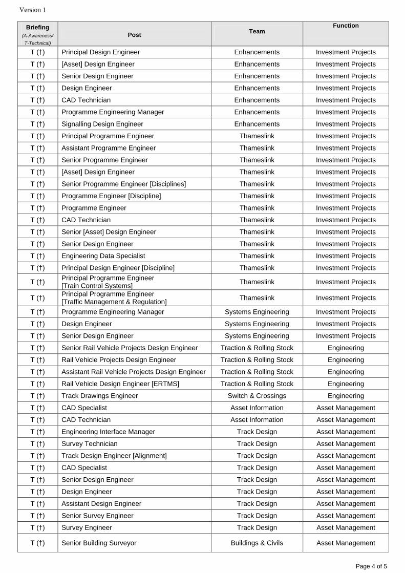
Briefing (A-Awareness/ T-Technical)
Post Team
Function
T (†) Principal Design Engineer Enhancements Investment Projects
T (†) [Asset] Design Engineer Enhancements Investment Projects
T (†) Senior Design Engineer Enhancements Investment Projects
T (†) Design Engineer Enhancements Investment Projects
T (†) CAD Technician Enhancements Investment Projects
T (†) Programme Engineering Manager Enhancements Investment Projects
T (†) Signalling Design Engineer Enhancements Investment Projects
T (†) Principal Programme Engineer Thameslink Investment Projects
T (†) Assistant Programme Engineer Thameslink Investment Projects
T (†) Senior Programme Engineer Thameslink Investment Projects
T (†) [Asset] Design Engineer Thameslink Investment Projects
T (†) Senior Programme Engineer [Disciplines] Thameslink Investment Projects
T (†) Programme Engineer [Discipline] Thameslink Investment Projects
T (†) Programme Engineer Thameslink Investment Projects
T (†) CAD Technician Thameslink Investment Projects
T (†) Senior [Asset] Design Engineer Thameslink Investment Projects
T (†) Senior Design Engineer Thameslink Investment Projects
T (†) Engineering Data Specialist Thameslink Investment Projects
T (†) Principal Design Engineer [Discipline] Thameslink Investment Projects
T (†) Principal Programme Engineer [Train Control Systems] Thameslink Investment Projects
T (†) Principal Programme Engineer [Traffic Management & Regulation] Thameslink Investment Projects
T (†) Programme Engineering Manager Systems Engineering Investment Projects
T (†) Design Engineer Systems Engineering Investment Projects
T (†) Senior Design Engineer Systems Engineering Investment Projects
T (†) Senior Rail Vehicle Projects Design Engineer Traction & Rolling Stock Engineering
T (†) Rail Vehicle Projects Design Engineer Traction & Rolling Stock Engineering
T (†) Assistant Rail Vehicle Projects Design Engineer Traction & Rolling Stock Engineering
T (†) Rail Vehicle Design Engineer [ERTMS] Traction & Rolling Stock Engineering
T (†) Track Drawings Engineer Switch & Crossings Engineering
T (†) CAD Specialist Asset Information Asset Management
T (†) CAD Technician Asset Information Asset Management
T (†) Engineering Interface Manager Track Design Asset Management
T (†) Survey Technician Track Design Asset Management
T (†) Track Design Engineer [Alignment] Track Design Asset Management
T (†) CAD Specialist Track Design Asset Management
T (†) Senior Design Engineer Track Design Asset Management
T (†) Design Engineer Track Design Asset Management
T (†) Assistant Design Engineer Track Design Asset Management
T (†) Senior Survey Engineer Track Design Asset Management
T (†) Survey Engineer Track Design Asset Management
T (†) Senior Building Surveyor Buildings & Civils Asset Management
Version 1
Page 5 of 5
Briefing (A-Awareness/ T-Technical)
Post Team
Function
T (†) Building Surveyor Buildings & Civils Asset Management
T (†) Principal Architect Buildings & Civils Asset Management
T (†) Senior Architect Buildings & Civils Asset Management
T (†) Architect Buildings & Civils Asset Management
T (†) Strategic Traction Power Design Manager Traction Power Design Asset Management
T (†) Senior Traction Power Design Engineer Traction Power Design Asset Management
T (†) Assistant Senior Traction Power Design Engineer Traction Power Design Asset Management
T (†) Traction Power Design Engineer Traction Power Design Asset Management
T (†) Senior Traction System Development Engineer Traction Power Design Asset Management
T (†) Enhancements Manager Enhancements Team National Delivery Service
T (†) Records Technical Manager National Records Group Information Management
T (†) Records Controller National Records Group Information Management
T (†) Records Assistant National Records Group Information Management
A Programme Directors Investment Projects
A Head of Commercial Contracts & Procurement Investment Projects
A Project Management Teams All Project Teams Investment Projects
A Commercial Managers All Project Teams Investment Projects
A Project Engineers All Project Teams Investment Projects
A Commercial Manager Contracts and Procurement Team National Delivery Service
A Principal Contractor Licence Holders (where applicable)
*NOTE: Contractors are responsible for arranging and undertaking their own Technical and Awareness Briefings in accordance with their own processes and procedure (†) Technical Briefing required only for individuals holding an identified post and who has appropriate duties / competencies affected by this standard.