Embed Size (px)
Citation preview

User guide Please read the Important notice and the Safety precautions and the Warnings V1.0
www.infineon.com page 1 of 31 2020-10-16
UG-2020-19
REF_Fridge_D111T_MOS user guide
Refrigerator compressor driver reference design kit
About this document
Scope and purpose
This user guide provides an overview of the reference design board REF_Fridge_D111T_MOS including its main features, key data, pin assignments and mechanical dimensions, and the guidance on how to run and design the motor with board.
The REF_Fridge_D111T_MOS board is a complete reference design board designed for refrigerator
compressors. It demonstrates the whole Infineon solution including digital motor control IC iMOTIONTM Smart Driver IMD111T-6F040 and the 600 V CoolMOSTM PFD7 super junction MOSFET.
The REF_Fridge_D111T_MOS board is developed to support customers in designing their refrigerator compressor drivers with Infineon products.
Intended audience
This user guide is intended for technical specialists working with the REF_Fridge_D111T_MOS board and
refrigerator compressor driver design.
Reference Board/Kit
Product(s) embedded on a PCB, with focus on specific applications and defined use cases that can include Software. PCB and auxiliary circuits are optimized for the requirements of the target application.
Note: Boards do not necessarily meet safety, EMI, quality standards (for example UL, CE) requirements.

User guide 2 of 31 V1.0
2020-10-16
REF_Fridge_D111T_MOS user guide Refrigerator compressor driver reference design kit
Important notice
Important notice
“Evaluation Boards and Reference Boards” shall mean products embedded on a printed circuit board
(PCB) for demonstration and/or evaluation purposes, which include, without limitation, demonstration, reference and evaluation boards, kits and design (collectively referred to as “Reference Board”).
Environmental conditions have been considered in the design of the Evaluation Boards and Reference Boards provided by Infineon Technologies. The design of the Evaluation Boards and Reference Boards has been tested by Infineon Technologies only as described in this document. The design is not qualified
in terms of safety requirements, manufacturing and operation over the entire operating temperature
range or lifetime. The Evaluation Boards and Reference Boards provided by Infineon Technologies are subject to functional
testing only under typical load conditions. Evaluation Boards and Reference Boards are not subject to the
same procedures as regular products regarding returned material analysis (RMA), process change notification (PCN) and product discontinuation (PD).
Evaluation Boards and Reference Boards are not commercialized products, and are solely intended for
evaluation and testing purposes. In particular, they shall not be used for reliability testing or production. The Evaluation Boards and Reference Boards may therefore not comply with CE or similar standards
(including but not limited to the EMC Directive 2004/EC/108 and the EMC Act) and may not fulfill other requirements of the country in which they are operated by the customer. The customer shall ensure that
all Evaluation Boards and Reference Boards will be handled in a way which is compliant with the relevant
requirements and standards of the country in which they are operated.
The Evaluation Boards and Reference Boards as well as the information provided in this document are
addressed only to qualified and skilled technical staff, for laboratory usage, and shall be used and
managed according to the terms and conditions set forth in this document and in other related
documentation supplied with the respective Evaluation Board or Reference Board. It is the responsibility of the customer’s technical departments to evaluate the suitability of the Evaluation Boards and Reference Boards for the intended application, and to evaluate the completeness
and correctness of the information provided in this document with respect to such application. The customer is obliged to ensure that the use of the Evaluation Boards and Reference Boards does not
cause any harm to persons or third party property.
The Evaluation Boards and Reference Boards and any information in this document is provided "as is"
and Infineon Technologies disclaims any warranties, express or implied, including but not limited to
warranties of non-infringement of third party rights and implied warranties of fitness for any purpose, or
for merchantability.
Infineon Technologies shall not be responsible for any damages resulting from the use of the Evaluation Boards and Reference Boards and/or from any information provided in this document. The customer is obliged to defend, indemnify and hold Infineon Technologies harmless from and against any claims or
damages arising out of or resulting from any use thereof.
Infineon Technologies reserves the right to modify this document and/or any information provided herein at any time without further notice.

User guide 3 of 31 V1.0
2020-10-16
REF_Fridge_D111T_MOS user guide Refrigerator compressor driver reference design kit
Safety precautions
Safety precautions
Note: Please note the following warnings regarding the hazards associated with development systems.
Table 1 Safety precautions
Warning: The DC link potential of this board is up to 400 VDC. When measuring voltage waveforms by oscilloscope, high voltage differential probes must be used. Failure to do
so may result in personal injury or death.
Warning: The evaluation or reference board contains DC bus capacitors which take time to discharge after removal of the main supply. Before working on the drive system, wait five minutes for capacitors to discharge to safe voltage levels. Failure to
do so may result in personal injury or death. Darkened display LEDs are not an
indication that capacitors have discharged to safe voltage levels.
Warning: The evaluation or reference board is connected to the grid input during testing. Hence, high-voltage differential probes must be used when measuring voltage
waveforms by oscilloscope. Failure to do so may result in personal injury or death.
Darkened display LEDs are not an indication that capacitors have discharged to safe
voltage levels.
Warning: Remove or disconnect power from the drive before you disconnect or reconnect wires, or perform maintenance work. Wait five minutes after removing
power to discharge the bus capacitors. Do not attempt to service the drive until the bus capacitors have discharged to zero. Failure to do so may result in personal injury or
death.
Caution: The heat sink and device surfaces of the evaluation or reference board may
become hot during testing. Hence, necessary precautions are required while handling
the board. Failure to comply may cause injury.
Caution: Only personnel familiar with the drive, power electronics and associated
machinery should plan, install, commission and subsequently service the system.
Failure to comply may result in personal injury and/or equipment damage.
Caution: The evaluation or reference board contains parts and assemblies sensitive to electrostatic discharge (ESD). Electrostatic control precautions are required when
installing, testing, servicing or repairing the assembly. Component damage may result if ESD control procedures are not followed. If you are not familiar with electrostatic
control procedures, refer to the applicable ESD protection handbooks and guidelines.
Caution: A drive that is incorrectly applied or installed can lead to component damage or reduction in product lifetime. Wiring or application errors such as undersizing the
motor, supplying an incorrect or inadequate AC supply, or excessive ambient
temperatures may result in system malfunction.
Caution: The evaluation or reference board is shipped with packing materials that need to be removed prior to installation. Failure to remove all packing materials that are unnecessary for system installation may result in overheating or abnormal
operating conditions.

User guide 4 of 31 V1.0
2020-10-16
REF_Fridge_D111T_MOS user guide Refrigerator compressor driver reference design kit
Table of contents
Table of contents
About this document ....................................................................................................................... 1
Important notice ............................................................................................................................ 2
Safety precautions .......................................................................................................................... 3
Table of contents ............................................................................................................................ 4
1 The reference board at a glance ............................................................................................... 5 1.1 Delivery content ...................................................................................................................................... 5
1.2 Block diagram .......................................................................................................................................... 5
1.3 Main features ........................................................................................................................................... 6 1.4 Board parameters and technical data .................................................................................................... 7
2 System and functional description ........................................................................................... 8
2.1 Commissioning ........................................................................................................................................ 8
2.1.1 Hardware connection ........................................................................................................................ 9 2.1.2 Software/firmware preparation ........................................................................................................ 9
2.1.3 Program firmware/parameters/script............................................................................................. 10 2.1.4 Open-loop diagnostic ...................................................................................................................... 12 2.1.5 Closed-loop run ................................................................................................................................ 13
2.2 Description of the functional blocks ..................................................................................................... 14 2.2.1 Inverter stage ................................................................................................................................... 14 2.2.2 DC bus sensing and MCEWizard configuration ............................................................................... 15
2.2.3 Current sensing and over-current protection ................................................................................. 16
2.2.3.1 Current sensing ........................................................................................................................... 16
2.2.3.2 Over-current protection.............................................................................................................. 18 2.2.4 NTC sensing and thermal protection .............................................................................................. 18
2.3 Frequency-signal interface ................................................................................................................... 20
3 System design ...................................................................................................................... 22
3.1 Schematics ............................................................................................................................................ 22 3.2 Layout .................................................................................................................................................... 22
3.3 Bill of material ....................................................................................................................................... 23 3.4 Connector details .................................................................................................................................. 24
4 System performance ............................................................................................................. 26 4.1 Thermal characterization test .............................................................................................................. 26 4.2 MOSFET dV/dt test................................................................................................................................. 27
5 Reference and appendices ..................................................................................................... 29 5.1 Abbreviations and definitions ............................................................................................................... 29
5.2 References ............................................................................................................................................. 29
5.3 Additional information .......................................................................................................................... 29
Revision history............................................................................................................................. 30

User guide 5 of 31 V1.0
2020-10-16
REF_Fridge_D111T_MOS user guide Refrigerator compressor driver reference design kit
The reference board at a glance
1 The reference board at a glance
The REF_Fridge_D111T_MOS reference design kit is a part of the iMOTION™ reference design kit for motor
drives, which is aimed at refrigerator-compressor driver applications. The kit is a ready-to-use solution in combination with full Infineon products such as 600 V CoolMOSTM PFD7 super-junction MOSFET in a small SOT223 package, and motor-control smart driver iMOTIONTM IMD111T-F040. It can easily be switched to a final mass production application board, and has a fast time to market.
The REF_Fridge_D111T_MOS reference board is available from Infineon. The features of this board are described in Chapter 1.3 of this document (UG-2020-19). The remaining sections provide information to enable
customers to copy, modify and qualify the design for production according to their own specific requirements.
Environmental conditions have been considered in the design of the REF_Fridge_D111T_MOS. The design was
tested as described in this document, but not qualified in terms of safety requirements or manufacturing and operation over the whole operating temperature range or lifetime. The boards provided by Infineon are subject to functional testing only.
The boards are not subject to the same procedures as regular products in terms of returned material analysis (RMA), process change notification (PCN) and product discontinuation (PD). Evaluation boards are intended to be used under laboratory conditions by specialists only.
1.1 Delivery content
The delivery content only contains the board as Figure 2 shown, the detail ordering information is indicated in the Table 2.
The iMOTIONTM Link cable shown in the Figure 4 is mandatory for the tuning, and it is not included in the
delivery content, please order it if you do not have, ordering information can be found in the Section 5.3.
Table 2 Delivery content
1.2 Block diagram
Figure 1 Block diagram of the REF_Fridge_D111T_MOS reference board
Base part number Package Standard pack Orderable part number
Form Quantity
REF_Fridge_D111T_MOS
Boxed 1 REFFRIDGED111TMOSTOBO1

User guide 6 of 31 V1.0
2020-10-16
REF_Fridge_D111T_MOS user guide Refrigerator compressor driver reference design kit
The reference board at a glance
Figure 1 shows the block diagram of reference design kit REF_Fridge_D111T_MOS, and this document explains the features and details.
Figure 2 depicts the functional groups of the board. Connecter definition details are described in section 3.4. Please see this section if you need more information.
Figure 2 Functional groups on top side of board
1.3 Main features
REF_Fridge_D111T_MOS is a complete reference design board for refrigerator-compressor applications. Main features of the board include:
iMOTION™ Smart Driver IMD111T-6F040
Ready-to-use motion controller with scripting engine and 6-channel silicon on insulator (SOI) driver
600 V CoolMOS™ PFD7 – optimized technology with lowest Qrr, ESD protection and compact SOT223 surface mounted device (SMD) package
System solution enables best light-load efficiency and compact design
Key features of iMOTION™ Smart Driver IMD111T-6F040 include:
Motor controller with integrated high-voltage gate driver and voltage regulator
Integrated 5 V low dropout regulator (LDO) allows single 15 V supply voltage
Robust 600 V gate driver in thin-film SOI technology
Gate driver integrated with ultra-fast bootstrap diodes
Space saving LQFP 40-pin package with high-voltage creepage
Motion control engine (MCE) as ready-to-use solution for variable speed drives
1. EMI filter and rectifier group
2. DC bus capacitors
3. Motor phase connector
(J3)
4. CoolMOSTM MOSFET
5. Auxiliary power supply
6. IMD111T-6F040
7. AC line input connector
(J1)
8. iMOTIONTM Link connector
(J6)
9. Frequency input signal
connector (J2)
3
2
7
1
4
5
8
6
9

User guide 7 of 31 V1.0
2020-10-16
REF_Fridge_D111T_MOS user guide Refrigerator compressor driver reference design kit
The reference board at a glance
Sensorless field-oriented control (FOC) for permanent magnet synchronous motor (PMSM)
Flexible space vector PWM (3-phase PWM or 2-phase PWM)
Motor-current sensing via single or leg shunt
Optional analog or digital hall sensor interface
Flexible host interface options for motor control commands: universal asynchronous receiver/transmitter
(UART), frequency/duty cycle or analog VSP
IEC60335-1/UL60730 Class B Safety Software certificate
For more information about the above-mentioned products, refer to the corresponding reference materials.
1.4 Board parameters and technical data
Table 3 depicts the important specifications of the reference design REF_Fridge_D111T_MOS.
Table 3 REF_Fridge_D111T_MOS board specifications
Parameter Symbol Conditions / comments Value Unit
Operation input voltage Vac Lower AC input, less motor power output 165 ~ 265 Vrms
Maximum input current Iac(max) Input 220 VAC, Ta=25C 1.7 Arms
Maximum input power Pin(max) Input 220 VAC, fPWM=5 kHz, Ta=25°C, Tcase= 100°C
without heat sink
250 W
Maximum motor current Imtr(max) Input 220 VAC, fPWM=5 kHz, Ta=25°C, Tcase= 100°C
without heat sink
0.69 Arms
Maximum DC bus voltage Vdc(max) 400 V
Shunt Resistance Rsh 250 mΩ
Protection
Current protection
trigger level
Itrip Set in the MCEWizard - Apeak
Thermal protection level Tprotection Temperature gap between MOSFET’s case and NTC (negative temperature coefficient) sensor needs to
be considered; recommended is a setting of
maximum 105°C for the case temperature,
considering the gap, set 75°C in the MCEWizard.
75 °C
Auxiliary power supply 1 - 15V
Output voltage Vout1 Used for IMD111T-6F040,integrate 5 V LDO in the
IMD111T-6F040
15 ± 5% V
Maximum output current Iout1 100 mA
PCB characteristics
Dimension Length × width × height 78×78×46 mm
Material 1.6 mm thickness, 1 oz. copper FR4
System environment
Ambient temperature Ta Non-condensing, maximum RH of 95% 0 ~ 50 °C

User guide 8 of 31 V1.0
2020-10-16
REF_Fridge_D111T_MOS user guide Refrigerator compressor driver reference design kit
System and functional description
2 System and functional description
2.1 Commissioning
Hardware connection
Programm firmware/parameters/script
Software/firmware preparation
Open-loop diagnostic
Closed-loop run
1- iMOTIONTM Link to bridge the MCE and PC2- Connect AC source (J1) and motor (J3)
1- Program the firmware/parameters through the iMOITIONTM Link by MCEDesigner, IMD111T can be powered up by iMOTIONTM Link, or be powered by auxiliary power supply on the board after the AC source is powered2- Program script file if available
1 - Install MCEDesigner/MCEWizard 2 - Download the firmware of MCE3 - Generate parameters file (.txt) by MCEWizard, Which is used to transfer the hardware/motor parameters to register s values4 - Generate script file if available
1- Power up AC power supply2- Run build-in function VF diagnostic to verify current/DC bus sensing, hardware connection and parameters
1- Run motor in closed-loop mode by start motor function, tune the parameters
Figure 3 Basic process for running the motor the first time
This section describes how to get the system working when user first installs the board (refer to Figure 3 for general steps). The following items detail these steps. For those who are already familiar with the system, or have already run the board, unnecessary steps can be skipped depending on user’s actual situation. For more
in-depth commissioning process requirements, please refer to the MCE reference manual or the corresponding
reference material [4][5][6].

User guide 9 of 31 V1.0
2020-10-16
REF_Fridge_D111T_MOS user guide Refrigerator compressor driver reference design kit
System and functional description
2.1.1 Hardware connection
Figure 4 shows the hardware connection details for the reference design board.
iMOTIONTM Link cable is needed to bridge the PC/debugger side and motor drive system (the target iMOTION™ device, hot side) with 1 kV DC galvanic isolation. Users can go to Section 5.3 for more information about iMOTIONTM
Link.
1. Connect iMOTIONTM Link’s 8-pin cable to J6 with default pin order, and connect PC and iMOTIONTM Link with
the USB wire.
2. Then connect AC power supply (J1) and the motor (J3).
Figure 4 Hardware connection details
2.1.2 Software/firmware preparation
1. The iMOTION™ software tools MCEDesigner and MCEWizard are required to set up the system, as well as to
control and fine-tune the system performance to match users' exact needs. These tools are available for download via the Infineon website (http://www.infineon.com/imotion-software). Please check this page periodically for tool/software updates.
2. The MCE firmware then has to be downloaded on our website; select the proper version of the firmware
based on your requirements. Included in the package are the firmware (‘.ldf’), default parameters (‘.txt’), default map file (‘.map’), the file for the MCEDesigner (‘.irc’) and other documents.
3. Generate your parameters’ file.
Use MCEWizard to enter the target motor’s system and operating parameters, as well as reference board’s hardware parameters, which will then be used to calculate the controller’s digital parameter set
representing the complete motor drive system.

User guide 10 of 31 V1.0
2020-10-16
REF_Fridge_D111T_MOS user guide Refrigerator compressor driver reference design kit
System and functional description
After system and operating parameters are set, go to the “Verify & Save Page” and click on “Calculate” button. If no errors are reported, then save the drive parameter set in your project directory by clicking
“Export to Designer file (.txt)” (Figure 7); if some errors are detected, double-click on the error message (highlighted in RED) and adjust the related parameters. Saved Drive System Parameter File will be later used
for programmers.
Note: After you log-in on myInfineon, you could download the default MCEwizard file (.mc2) for this
board, you only need to modify the parameters related to your motor to make things easier and save time
4. Generate the script if available. For users who are running the board for the first time, it is recommended not to use this function first, but to add the script function after the motor performance commissioning is
completed.
2.1.3 Program firmware/parameters/script
The REF_Fridge_D111T_MOS reference design kit is shipped with pre-programmed firmware and default parameters, since the functional tests were done before the shipment. Users need to program their
parameters, as the motor is different from the one under test.
The following steps have to be performed in order to make a blank IMD111T working:
Program the firmware of the MCE
Program parameter sets for system and motor
Program customer script file (optional)
Or
Program the combined file, which is combined by MCEWizard containing all three items above. Customer script file is optional depending on whether it is available. The combined file is usually used for production, since it only needs to be programmed once.
The programming process is as follows:
1. Start the MCEDesigner tool and open MCEDesigner default configuration file (‘.irc’) for IMD111T device (IMD111T_Vxxx.irc) by clicking “File” > “Open.”
Note: The IMD111T_Vxxx.irc file is included in the downloaded firmware package “IMD111T MCE
Software Package.”
2. Power the iMOTIONTM control IC with 3.3 V. It is recommended to program the IC with the 3.3 V isolated
power supply that comes from the iMOTIONTM Link; there is a switch on the iMOTIONTM Link to enable the 3.3 V output. The iMOTIONTM control IC will also be powered by the on-board auxiliary power supply after the AC source is powered, but caution due to high voltage.
Note: The output voltage of LDO combined in the IMD111T-6F040 is 5 V, i.e. the controller of IMD111T-6F040 is powered by 5 V. However, it is also possible to use the 3.3 V power supply in the iMOTIONTM
Link to power the IMD111T-6F040 (for programmers).
3. MCEDesigner should automatically connect to the board using default COM port (Indicated by green circle
next to “COMx Up” status in the bottom frame of the MCEDesigner GUI) when iMOTIONTM control IC is
powered. If it cannot establish the connection due to an incorrect COM port, change COM port by doing the

User guide 11 of 31 V1.0
2020-10-16
REF_Fridge_D111T_MOS user guide Refrigerator compressor driver reference design kit
System and functional description
following: click on the “System Page” window and then click on “Preferences > Connection > Connect using,” and choose one of the other available COM ports from the drop-down list.
4. (In case blank IC) If the firmware has been erased from the IMD111T, the following warning message will pop up “Target device firmware and parameters file are not programmed! Please program firmware and parameters file” as Figure 5. Then you can program the firmware and parameters as described in the Step 5.
If it is not the blank IC, no such message will be indicated.
Figure 5 MCEDesigner warning message
5. Use the following steps to program the firmware and the parameters’ file into the internal Flash memory of
iMOTION™ Control IC: click on system page, click “Tools” > “Programmer” and select “Program Firmware and Parameters.” Shown as Figure 6 below. The encrypted firmware is available at “IMD111T MCE Software
Package;” regarding the parameters file, browse and select the’.txt’ file in the section 2.1.2.
Figure 6 Program the parameters and firmware

User guide 12 of 31 V1.0
2020-10-16
REF_Fridge_D111T_MOS user guide Refrigerator compressor driver reference design kit
System and functional description
Figure 7 MCEWizard verify and save page
2.1.4 Open-loop diagnostic
Double-click the “VF Diagnostic” function in the window of motor1, and monitor motor current with
oscilloscope. If motor current is not sinusoidal, change register TargetSpeed and Vd_Ext in VF Diagnostic sub-function, then double-click “VF Diagnostic” until the oscilloscope shows a steady sinusoidal current with an amplitude of 30~50% motor rate current.
Double-click “Iu & Iv_Slow” in System page > Monitor Definitions, the motor current feedback should be very clean and sinusoidal, as shown in Figure 8; otherwise please tune “Gating Propagation Delay & Phase Shift
Window Size” in MCEWizard.
“VF Diagnostic” sub-function can verify:
If motor is connected correctly
If IGBT(or MOSFET ) and gate driver work as expected
If current-sensing related parameters are correctly configured
If PCB layout and DC bus decoupling have been done correctly
After “VF Diagnostic” is done, click STOP button (the red traffic light button) or run “stop motor” function to stop the motor.

User guide 13 of 31 V1.0
2020-10-16
REF_Fridge_D111T_MOS user guide Refrigerator compressor driver reference design kit
System and functional description
Figure 8 Trace waveform for Iu & Iv open loop diagnostic
2.1.5 Closed-loop run
If the VF Diagnostic works correctly, the hardware circuit and signal sampling will work normally, at which point we can try to run the motor in a closed-loop mode. The steps are listed below.
1. Start the motor by clicking the green traffic light button in the control bar (or double click Start Motor sub-
function in the window of motor1 , which is in the group of User Application Function Definitions), the motor
will run if above step works well.
2. Check the motor spin direction, adjust the connection order of the motor’s winding, or set negative TargetSpeed in MCEDesigner if the direction is wrong.
3. Set TargetSpeed to about 50% of maximum speed, start “Iu & Flx_M” trace with “Auto Repeat On Level,” see
Figure 9. Flx_M is good within the range of 2000~2500 (rated value is 2048), and must be steady and DC-like.
Here are some key tips for better motor performance tuning:
If Flx_M is not steady (swing or oscillation), motor parameters, speed loop PI gain, flux estimator time constant and PLL PI bandwidth (parameters PLLKp and PLLKi) and releated setup need to be checked.
If Flx_M is very noisy, current feedback and Vdc-related hardware and parameters need to be checked.
If Flx_M does not come close to 2048, “Motor Back EMF Constant (Ke)” needs to be adjusted in MCEWizard.

User guide 14 of 31 V1.0
2020-10-16
REF_Fridge_D111T_MOS user guide Refrigerator compressor driver reference design kit
System and functional description
Figure 9 Trace waveform for Iu & Flx-M at 50% speed
4. Once the firmware has been programmed, and a new parameters’ file has to be programmed, follow the
same instructions given in Section 2.1.3. In this case, the firmware programming is no longer needed, and you can select the first option “Program Parameters.”
Note: For detailed information on controller programming, refer to AN2018-33 iMOTION™ 2.0 Device
Programming, MCEDesigner documentation and MCEWizard documentation.
2.2 Description of the functional blocks
2.2.1 Inverter stage
The inverter section is implemented with the 600 V CoolMOSTM PFD7 super-junction MOSFET in a small SOT223 package. The PFD7 high-voltage, n-channel MOSFET series combines best-in-class performance with state-of-
the-art ease of use, shaped by Infineon’s experience of more than 20 years as a pioneer in super-junction
technology innovation. The products come with an integrated fast body diode ensuring a robust device, and in turn, a reduced BOM for the customer. Figure 10 shows the diagram of the inverter and peripheral circuit.

User guide 15 of 31 V1.0
2020-10-16
REF_Fridge_D111T_MOS user guide Refrigerator compressor driver reference design kit
System and functional description
Figure 10 Inverter and peripheral circuit
2.2.2 DC bus sensing and MCEWizard configuration
Figure 11 provides the DC bus sensing resistor details on the reference design.
The high-side resistors are 2 MΩ and the low-side resistor is 20 kΩ, the default DC bus sensing voltage results in
a range of 0 to 5 V on the ADC input, reflecting a range of 0 to 505 V.
Figure 11 DC bus sensing

User guide 16 of 31 V1.0
2020-10-16
REF_Fridge_D111T_MOS user guide Refrigerator compressor driver reference design kit
System and functional description
The hardware parameters need to be configured in MCEWizard as shown in Figure 12.
Figure 12 DC bus sensing configuration in MCEWizard
The Vdc-sensing, low-pass-filter time constant is ((R10 + R13) // R15) * C4= (2 MΩ // 20 kΩ) * 4.7 nF = 93.1 µs, C17
can be adjusted to higher capacitance for clean Vdc sensing.
2.2.3 Current sensing and over-current protection
2.2.3.1 Current sensing
The current sensing on this board uses only the RC network for operational bias and low-pass filter to minimize the cost. No additional operational amplifier is needed.
Based on the principle of Kirchhoff's voltage law, and assuming the AD port input impedance is infinite, you
obtain the equation below.
𝑉𝐴𝐷𝐶 =(𝑉𝑐𝑐 − 𝑉𝑠ℎ𝑢𝑛𝑡)
𝑅1 + 𝑅2∗ 𝑅1 + 𝑉𝑠ℎ𝑢𝑛𝑡
The equation can be transformed to two parts as shown here:
𝑉𝐴𝐷𝐶 =𝑅2 ∗ 𝑉𝑠ℎ𝑢𝑛𝑡
𝑅1 + 𝑅2+
𝑅1 ∗ 𝑉𝑐𝑐
𝑅1 + 𝑅2
The impedance of the RC network is much larger than the 𝑅𝑠ℎ𝑢𝑛𝑡, so it can be assumed that:
𝑉𝑠ℎ𝑢𝑛𝑡 = 𝐼𝑠ℎ𝑢𝑛𝑡 ∗ 𝑅𝑠ℎ𝑢𝑛𝑡

User guide 17 of 31 V1.0
2020-10-16
REF_Fridge_D111T_MOS user guide Refrigerator compressor driver reference design kit
System and functional description
VADC can then be written as:
𝑉𝐴𝐷𝐶 =𝑅2
𝑅1 + 𝑅2∗ 𝑅𝑠ℎ𝑢𝑛𝑡 ∗ 𝐼𝑠ℎ𝑢𝑛𝑡 +
𝑅1 ∗ 𝑉𝑐𝑐
𝑅1 + 𝑅2
Where 𝑅1∗𝑉𝑐𝑐
𝑅1+𝑅2 is the offset, and
𝑅2
𝑅1+𝑅2∗ 𝑅𝑠ℎ𝑢𝑛𝑡 is the gain of the shunt current.
Figure 13 Current-sensing topology
Use this board with, for example, R1 = R20 = 2 k, R2 = R8 = 22.1 k, Vcc = 5 V, offset = 0.415V, gain = 𝑅2
𝑅1+𝑅2∗ 𝑅𝑠ℎ𝑢𝑛𝑡 = 229.3 mV/A.
Note the following points concerning current sampling:
R8 & R20 also determine ADC operational bias for current sensing, which corresponds to the motor regeneration operation range. For those applications that do not work at regenerative brake mode, the bias can be as low as possible to reserve enough ADC range for the drive mode, since negative current to DC bus
does not occur.
Since the gain of the external RC circuit is less than 1, internal signal amplification is required to increase the
ADC input voltage range with lower shunt value. If a larger shunt is chosen, the power loss and size are both larger. MCE provides an inner current sampling amplifier with *1, *3, *6 and *12 gain selections, which can
be configured in the MCEWizard.
There is no common mode noise-rejection ability without an outer operational amplifier, so the GND network of the PCB needs to be dealt with very carefully, since any voltage difference between IMD111T’s ADC ground and shunt resistor ground will be considered as an “input signal,” and will deteriorate control performance or increase audible noise.

User guide 18 of 31 V1.0
2020-10-16
REF_Fridge_D111T_MOS user guide Refrigerator compressor driver reference design kit
System and functional description
Figure 14 Current-sensing circuit on the board
2.2.3.2 Over-current protection
The over-current condition can be detected by IMD111T-6F040 by the input sources as shown in Figure 15.
Internal comparator in the IMD111T-6F040
Figure 15 Over-current protection on the board
For more details about the over-current protection (OCP) in the IMD111T, refer to chapter on motor over-
current protection in the reference material [6].
The internal comparator’s reference level is set by the internal DAC, the level can be set in the MCEWizard by “Device over-current trigger level setting for comparator” and “Motor1 current input to ADC offset voltage.” The DAC output pin REFU needs to be connected to a capacitor; 10 nF/16 V is used on the board.
2.2.4 NTC sensing and thermal protection
Pin 35 of IMD111T-6F040 is the ADC port dedicated to NTC temperature sampling. On the board, an NTC is connected to the ADC channel by the circuit shown in Figure 16. The position of the NTC on the board is shown
in the Figure 17

User guide 19 of 31 V1.0
2020-10-16
REF_Fridge_D111T_MOS user guide Refrigerator compressor driver reference design kit
System and functional description
Figure 16 NTC sensing circuit
NTC
Figure 17 NTC position on the board
The parameters of the NTC are: B-constant = 4050 K 1%, R25 = 47 k 1%. Based on the typical value of the thermistor resistance, voltage of the Vth can be obtained in Table 4.
The firmware inside the IMD111T integrates the over-temperature protection device, which will be triggered by
the voltage Vth. Simply set the proper trigger level in the MCEWizard. More information can be found in the over-
temperature protection section of the reference material [6].

User guide 20 of 31 V1.0
2020-10-16
REF_Fridge_D111T_MOS user guide Refrigerator compressor driver reference design kit
System and functional description
Table 4 Thermistor characteristics with V = 5 V,R5=4.87 k
Temperature (C) Resistance typ. (k) Vth (V) Vth register value
15.00 75.31 4.70 3846
20.00 59.25 4.62 3784
25.00 47.00 4.53 3711
30.00 37.57 4.43 3625
35.00 30.25 4.31 3527
40.00 24.52 4.17 3416
45.00 20.01 4.02 3293
50.00 16.43 3.86 3159
55.00 13.58 3.68 3014
60.00 11.28 3.49 2860
65.00 9.42 3.30 2700
70.00 7.92 3.10 2535
75.00 6.68 2.89 2369
80.00 5.67 2.69 2202
85.00 4.83 2.49 2039
90.00 4.13 2.30 1880
95.00 3.55 2.11 1727
100.00 3.06 1.93 1582
105.00 2.65 1.76 1445
110.00 2.31 1.61 1317
115.00 2.01 1.46 1198
2.3 Frequency-signal interface
Since current refrigerator applications mainly use frequency signals to control the compressor speed, the board is designed with a frequency-signal interface. Figure 18 shows the interface circuit. The input signal is isolated from the control and power parts on the board.
The board has two types of input interface:
1. Square-wave interface (default, remove the D3, R15 )
2. AC 220 V as the control input (you need to remove R18, and install D3, R15)
Type 1 is a more common signal type, while type two is used less, leaving only the interface for customers who
need it.
Figure 18 Frequency-interface circuit

User guide 21 of 31 V1.0
2020-10-16
REF_Fridge_D111T_MOS user guide Refrigerator compressor driver reference design kit
System and functional description
A typical square wave input signal for refrigerator applications is shown in Table 5 for reference.
Table 5 Typical frequency/speed characteristic
Signal frequency fn (Hz) Motor speed n (RPM)
fn < 30 Stop
30 ≤ fn < 40 Minimum speed
40 ≤ fn < 150 30 * fn
150 ≤ fn < 200 Maximum speed
fn ≥ 200 Stop

User guide 22 of 31 V1.0
2020-10-16
REF_Fridge_D111T_MOS user guide Refrigerator compressor driver reference design kit
System design
3 System design
This section provides the complete details of the schematics, layout and connectors. Please note that the schematics, routing and Gerber generation are done in Altium Designer. Customers who are interested in the original Altium format files or pdf files for better clarity can visit www.Infineon.com.
3.1 Schematics
The major function blocks are introduced in Section 2.2. Customers who are interested in further details can download the design files after logging in your account on infineon webpage.
3.2 Layout
The board is designed in two layers, and its dimensions are 78 mm × 78 mm, manufactured with 1 oz. (35 µm) copper thickness. The project is designed with Altium Designer, and all design files can be downloaded after logging in your account on Infineon webpage.
Figure 19 Top view of the board

User guide 23 of 31 V1.0
2020-10-16
REF_Fridge_D111T_MOS user guide Refrigerator compressor driver reference design kit
System design
Figure 20 Bottom view of the board
Here are a few design tips to note for your reference:
Thermal performance
Maximizing the copper area of the collector could effectively reduce the IGBT junction temperature, so the
board can deliver more power.
Ground layout
Since current sampling is non-differential and without op-amp, the ground area should be carefully laid out;
the digital ground should refer to the shunt ground to ensure the sampling noise is correct.
3.3 Bill of material
The complete bill of material is available on the download section of the Infineon homepage. A log-in is required to download this material.

User guide 24 of 31 V1.0
2020-10-16
REF_Fridge_D111T_MOS user guide Refrigerator compressor driver reference design kit
System design
Table 6 BOM of the most important/critical parts of the reference board
S. No. Ref Designator Description Manufacturer Manufacturer P/N
1 U1 IC iMOTION SMART DRIVER
Infineon
Technologies IMD111T-6F040
2 Q2, Q3, Q4, Q5, Q6,
Q7
600 V CoolMOS PFD7 SJ Power
Device
Infineon
Technologies IPN60R1K0PFD7S
3 Q1 MOSFET N-CH 30 V 2.7 A SOT-23-3
Infineon
Technologies IRLML2030TRPBF
4 C19, C24 WCAP-CSGP General Purpose
Ceramic Capacitors, size 1206, 10
uF, +/-10%, 25 VDC
Wurth Elektronik 885012208069
5 C21 WCAP-ATG8 Aluminum Electrolytic Capacitors, 6.3x11
mm, 25 Vdc, 220 uF
Wurth Elektronik 860010473011
6 C27, C28 WCAP-AT1H THT Aluminum Electrolytic Capacitors, D16mm x L35.5 mm, 100 uF, +/-20%, 450
VDC
Wurth Elektronik 860241480001
7 C29, C30 WCAP-CSST Soft Termination Ceramic Capacitors, size 1206, 22
nF, +/-10%, 500 VDC
Wurth Elektronik 885382208010
8 J2 WR-WTB 2.54 mm Male Locking
Header, 2p
Wurth Elektronik 61900211121
9 J6 CONN HEADER VERT 8POS 2.54
mm
Wurth Elektronik 61300821121
10 L1 WE-CMB Common Mode Power
Line Choke, Type XS, 4 mH, 1.5 A,
250 V
Wurth Elektronik 744821240
11 RV1 WE-VD Disk Varistor, size 10 mm,
300 Vrms, 385 Vdc
Wurth Elektronik 820513011
12 RS1 RES 0.25 OHM 1% 3/4 W 2010
3.4 Connector details
Table 7 J1- AC line connector
PIN Label Function
1 L AC line input
2 N AC neutral input
3 N AC neutral input
Table 8 J2- Frequency input signal connector
PIN Label Function
1 Frequency input Frequency input signal, isolated by optocoupler
2 Frequency ground Frequency input signal ground, isolated by optocoupler

User guide 25 of 31 V1.0
2020-10-16
REF_Fridge_D111T_MOS user guide Refrigerator compressor driver reference design kit
System design
Table 9 J3- Motor side connector
PIN Label Function
1 W Connected to motor phase W
2 V Connected to motor phase V
3 U Connected to motor phase U
Table 10 J4- Earth connector
PIN Label Function
1 Earth
Table 11 J6- iMOTIONTM link connector
PIN Label Function
1 TXD1 User UART for script communication
2 RXD1 User UART for script communication
3 & 6 +3.3V On board 3.3 V supply
4 & 5 GND Ground
7 RXD0 MCEDesigner & firmware download
8 TXD0 MCEDesigner & firmware download

User guide 26 of 31 V1.0
2020-10-16
REF_Fridge_D111T_MOS user guide Refrigerator compressor driver reference design kit
System performance
4 System performance
4.1 Thermal characterization test
Figure 21 and Figure 22 show the thermal characterizations of REF_Fridge_D111T_MOS, based on 2 layers FR4 PCB with 1 oz. copper.
The tests reported on were performed under the following conditions: tamb=25°C, Vac = 220 V with different input
power until the MOSFET case reaches 100°C. There are two PWM frequencies (5 kHz and 16 kHz), and 3-phase
modulation mode only.
Figure 21 REF_Fridge_D111T_MOS thermal characterization case temperature – input power, ta =
25°C
Table 12 Input power and current characterization
Input power (W) 30 60 100 140 180 220 260
Input current (A) 0.24 0.45 0.72 1.03 1.32 1.6 1.81
30
40
50
60
70
80
90
100
110
0 50 100 150 200 250 300
Cas
e Te
mp
erat
ure
(
)
Input Power(W)
REF_Fridge_D111T_MOS Thermal characterization, Ta = 25
5kHz 16kHz

User guide 27 of 31 V1.0
2020-10-16
REF_Fridge_D111T_MOS user guide Refrigerator compressor driver reference design kit
System performance
Figure 22 REF_Fridge_D111T_MOS thermal characterization, case temperature - motor phase
current, ta = 25°C
4.2 MOSFET dV/dt test
This section indicates the MOSFET turn-on and turn-off waveform, the oscilloscope probe is connected as
shown in Figure 23. On the board, Rg (on) = 1 k, and Rg (off) = 47 . The dV/dt is calculated by the voltage varying
from 10% to 90%.
Figure 23 Drain-to-source voltage test - dV/dt control
As shown in Figure 24 and Figure 25, when the low-side MOSFET turns on, the Vds dV/dt = 245 V/28.1 ns = 8.7
V/ns. When the low-side MOSFET turns off, the dV/dt = 247.9 V/ 29.8 ns = 8.3 V/ns. Users may further adapt the Rg value to control MOSFET dv/dt if needed.
30
40
50
60
70
80
90
100
110
0.2 0.4 0.6 0.8
Cas
e Te
mp
erat
ure
(
)
Phase current (A)
REF_Fridge_D111T_MOS Thermal characterization, Ta = 25
5kHz 16kHz

User guide 28 of 31 V1.0
2020-10-16
REF_Fridge_D111T_MOS user guide Refrigerator compressor driver reference design kit
System performance
Figure 24 MOSFET turn-on waveform
Figure 25 MOSFET turn-off waveform
User guide 29 of 31 V1.0
2020-10-16
REF_Fridge_D111T_MOS user guide Refrigerator compressor driver reference design kit
Reference and appendices
5 Reference and appendices
5.1 Abbreviations and definitions
Table 13 Abbreviations
Abbreviation Meaning
CE Conformité Européenne
EMI Electromagnetic interference
UL Underwriters Laboratories
5.2 References
[1] Infineon Technologies AG. Datasheet of IPN60R1K0PFD7S (2019) V2.0 www.infineon.com
[2] Infineon Technologies AG. Datasheet of IMD111T-6F040 (2020) V1.0 www.infineon.com
[3] Infineon Technologies AG. Datasheet of IRLM2030TRPbF (2009) www.infineon.com
[4] Infineon Technologies AG. MCEWizard_V2.3.0.0 User Guide (2019) www.infineon.com
[5] Infineon Technologies AG. MCEDesigner_V2.3.0.0 Application Guide (2019) www.infineon.com
[6] Infineon Technologies AG. iMOTION™ Motion Control Engine Software Reference Manual (2020) V1.3 www.infineon.com
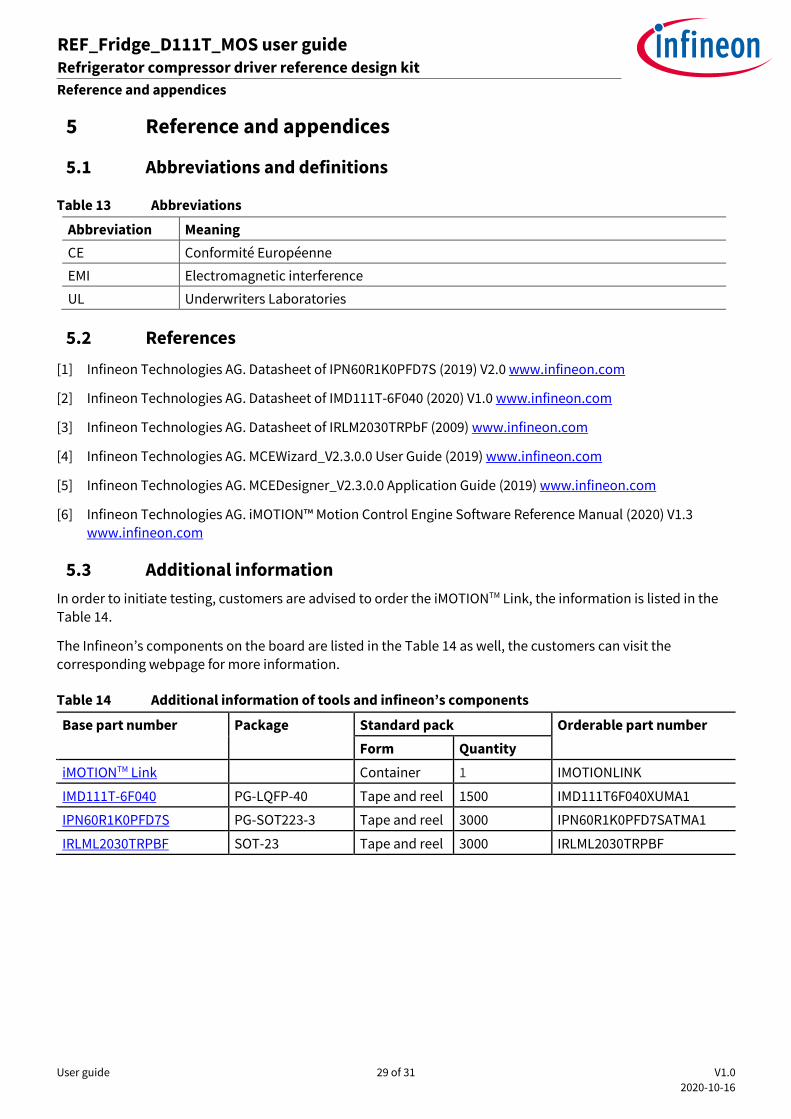
5.3 Additional information
In order to initiate testing, customers are advised to order the iMOTIONTM Link, the information is listed in the Table 14.
The Infineon’s components on the board are listed in the Table 14 as well, the customers can visit the
corresponding webpage for more information.
Table 14 Additional information of tools and infineon’s components
Base part number Package Standard pack Orderable part number
Form Quantity
iMOTIONTM Link Container 1 IMOTIONLINK
IMD111T-6F040 PG-LQFP-40 Tape and reel 1500 IMD111T6F040XUMA1
IPN60R1K0PFD7S PG-SOT223-3 Tape and reel 3000 IPN60R1K0PFD7SATMA1
IRLML2030TRPBF SOT-23 Tape and reel 3000 IRLML2030TRPBF

User guide 30 of 31 V1.0
2020-10-16
REF_Fridge_D111T_MOS user guide Refrigerator compressor driver reference design kit
Revision history
Revision history
Document
version Date of release Description of changes
1.0 2020/10/16 Initial version

Trademarks All referenced product or service names and trademarks are the property of their respective owners.
Edition 2020-10-16
UG-2020-19
Published by
Infineon Technologies AG
81726 Munich, Germany
© 2021 Infineon Technologies AG.
All Rights Reserved.
Do you have a question about this
document?
Email: [email protected]
Document reference
For further information on the product, technology, delivery terms and conditions and prices please contact your nearest Infineon Technologies office (www.infineon.com). WARNINGS Due to technical requirements products may contain dangerous substances. For information on the types in question please contact your nearest Infineon Technologies office. Except as otherwise explicitly approved by Infineon Technologies in a written document signed by authorized representatives of Infineon Technologies, Infineon Technologies’ products may not be used in any applications where a failure of the product or any consequences of the use thereof can reasonably be expected to result in personal injury.