Embed Size (px)
Citation preview
U.S. DEPARTMENT OF COMMERCENational Technical Information Service
AD-A036 497
REEFING OF PARACHUTESDRAG AREA RATIOS VS REEFING RATIOS
AERONAUTICAL SYSTEMS DIVISION
WRIGHT-PATTERSON AIR FORCE BASE, OHIO
JULY 1976
o REEFING OF rARACHUTES-DRAG AREA RATIOS VSREEFING RATIOS
DLRECThlATkX OF EQUIPMENT ENGINEERING
JULY 1978 ANA %sa
TECHNICAL REP•OUT ASD-TR-76-2-•(;fFINAL REPORT FOR PERIOD 1975/1976
Apod forpublt releaft; distribution unllmito
REPRODUCED PyNATIONAL TF,•HNI(,^
INFORMATION SERVICEU. S. DEPARTMFNT OF COMMERCE
SPIINGFIELD, VA. 2n61
DEPUTY FOR EN'GINEERINGAERONAUTICAL SYSTEMS DIVISIONAIR FORCE SYSTEMS COMMANDWRIGHT-PATTERSON AIR FORCE BASE, OHIO 45433
UNCLASSIFIEDS.CURITY CLASSIFICATION OF THIS PAGE ("nio Dame Entered_
REPORT DOCUMENTATION PAGE BEFORE MSTC FO.I, REPORT NUMBER .. . GOVT ACCESSION NO 3. RECIPIENT'S CATALOG NUMBER
ASD-TR-76-2
4. TITLF. (and Subtitle) S. TVPE OF REPORT 6 PERIOD COVEREDReefing of Parachutes - Drag Area Ratios vs Final In-house ReportReefing Ratios 1975/1976
S. PefIl'ORMIG ONG. REPORT NUMBER
•. AUTHOR:() S. CONT ACT OR GRANT HUMMERF()
'Theodote W. Knacke
S. PERFORMINO ORGANIZATION NAME AND ADDRESS 10. PROGRAWl' ELEMENT. PROJECT, TASK
AREA & WORK UNIT NUMBERS
Aeronautical Systems DivisionWright-Patterson AnB, Ohio
1I. CONTROLLING OFFICE NAME AND ADDRESS 1". REPORT DATEDirectorate of Equipment Engineering July 1976Aerial Delivery and Parachute Branch 1S. NUMBER OF PAGESAeronautical Systems Divisionwriaht-Patterson An-. Ohin 45431
14. MONITORING AGENCY NAME & ADDRESS(it dilferent from Controlling Ofice) 15. SECURITY CLASki. (of thli report)
Unclassified
'S.. DECLASSIFICAT.N/DOWN GRAVINGSCHEDULE
iS. DISTRIBUTION STATEMENT (of this Report)
Approved for public release; distribution unlimited.
17. DISTRIBUTION STATEMENT (o' Ihe abstract entered in Block 20, Ii different from Report)
1. SUPPLEMENTARY NOTES
19. KEY WORDS (Continue on reverse olde it necee•sary nd identify by block number)
ParachutesReefing MethodsDrag Area Ratio vs Re.efing Ratio
2C. ABSTRACT ('Continue an reverse ol*d |4' n©eessry and identify by block number)
Reefing data were collected and evaluated for the following parachute types:solid circular parachutes of flat, conical, and triconical design; extendWdskirt parachutes of 10 percent flat extended, 10 percent straight extended,and fully extended (14.3 percent) design; and slotted parachutes of ringslot,Ringsail, and flat and conical ribbon design. Various reefing terminologiesare discussed that have been used in the past and a recommendation is madefor a common terminclnst. Background data are provided for all parachutes
analyzed. (cont)
DD O 1473 EDITION OF 1 NoV 65 IS OBSOLETEDJAN 7 UNCLASSIFIEDSE$CURITY CLASSIFICATION OF THIS PAGE (When Date Entered)
wn Gov~rnent drawvngs, specliFicatIos, or other data a•re Lued for -kng purposeother than In conecfl on with a definitely telated Government procurement operation,Vo.. United States Government thereW incurs no rewponsi•ility nor any obligationahatsoeveri Ai the fact that the government my have formulated, furnished, or inany mly supplieJ the said drawings, specifications, or other data, is not to beregarded by spmlitoation or otherwise as .In any manner licensing the holder or ,nyother person or caruoration, or conveying any rights or permI&SIon to wmufacti.re,us&, or sell any patented Invention that may in any way be related thereto..
Thin report has beeu reviewed by the rnformation Office (10) and is releseableto the National Techcncal Information Service (N•T). At NTIS, it will beovailable to the general public, IncludTAS foreign nLtions.
This technicl- report han )'een reviewed and is approved for publication.
THBODOU W. KNACKEEngineering Consultant
FOR TUEE CONhW4IMK 'Al
.. ..... ........... .
~~ ~ ~ ~k .......... ..........................Chief, Crew I uipment and
Humen Factors DivisionDirectorate of Equipment L j...r... in...
Copies oi! this report should not be returned unles ret,'n Is required by recurity
considerations, contract4Ul obligations, or notice cn a specific docum•nt.
AIR FORE - 2• JAWIARY 77 - 50
2 1(0.!
UNCLASSIFIEDSECURITY CLASSIFICATION OF THIS PAC(E(Whan D4aW Xnfure&)
20. Cont
Drag area ratios vs reefing ratios are listed in tables and shown inindividual graphs ard in a summary chart for all parachutes investigated.
.ii
ii,
UNCLASSIFIEDSECURITY CLASSIFICATION OF THIS PAGE(W ne Date Entrero)
FOREWORD
This Technical Report was prepared by Mr. T. W. Knacke as aconsultant to the Division Adviscry Group (DAG), of the USAFAeronautical Systems Division (ASD), Wright-Patteisor. AFB, Ohio.Management supervision was provided by the Chief of the ASDParachute Branch, Mr. Herman Engel. Mr. Solomon Metres andMr. James DeWeese of the Flight Dynamics Laboratory, Recoveryand Crew Station Branch, together with Mr. H. Engel formed ateam directing the technical efforts.
The author wishes to acknowledge and express his appreciation,or the cooperation of Mr. James Reuther of the Pioneer ParachuteCompany, Mr. William Lewis of the US Army Natick Laboratories, theNorthrop Corporation - Ventura Division, Mr. William Pepper of theSandia Corporation, and Mr. Oscar Sepp of the ASD P-1 SystemProject Office. These people either provided data used in this.eport or helped to confirm existing data.
7'
.I
Si i I
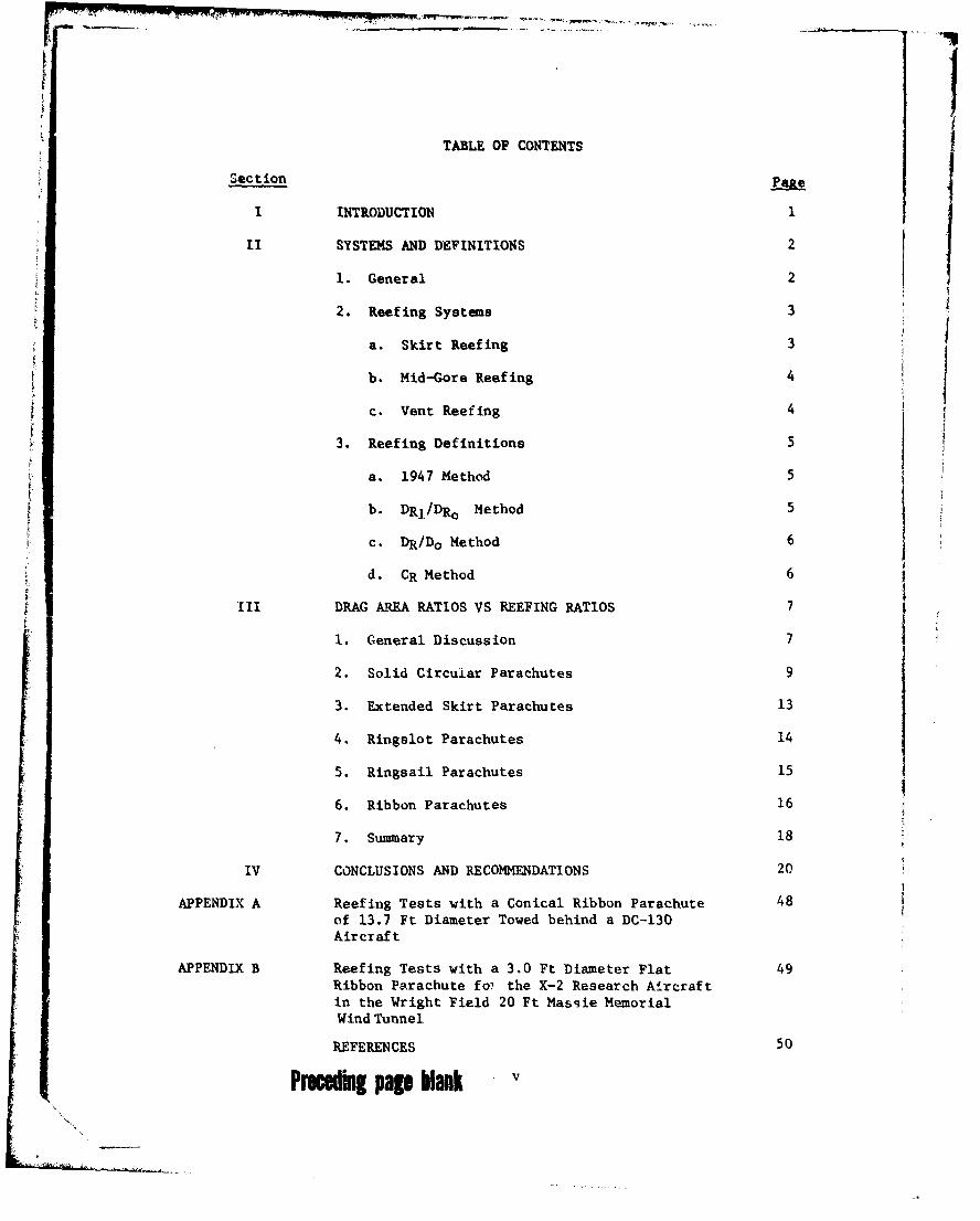
TABLE OF CONTENTS
Section
I INTRODUCTION 1
II SYSTEMS AND DEFINITIONS 2
1. General 2
2. Reefing Systems 3
a. Skirt Reefing 3
b. Mid-Gore Reefing 4
c. Vent Reefing 4
3. Reefing Definitions 5
a. 1947 Method 5
b. DR1 /DRo Method 5
c. DR/Do Method 6
d. CR Method 6
III DRAG AREA RATIOS VS REEFING RATIOS 7
1. General Discussion 7
2. Solid Circuiar Parachutes 9
3. Extended Skirt Parachutes 13
4. Ringslot Parachutes 14
5. Ringsail Parachutes 15
6. Ribbon Parachutes 16
7. Summary 18
IV CONCLUSIONS AND RECOMMENDATIONS 20
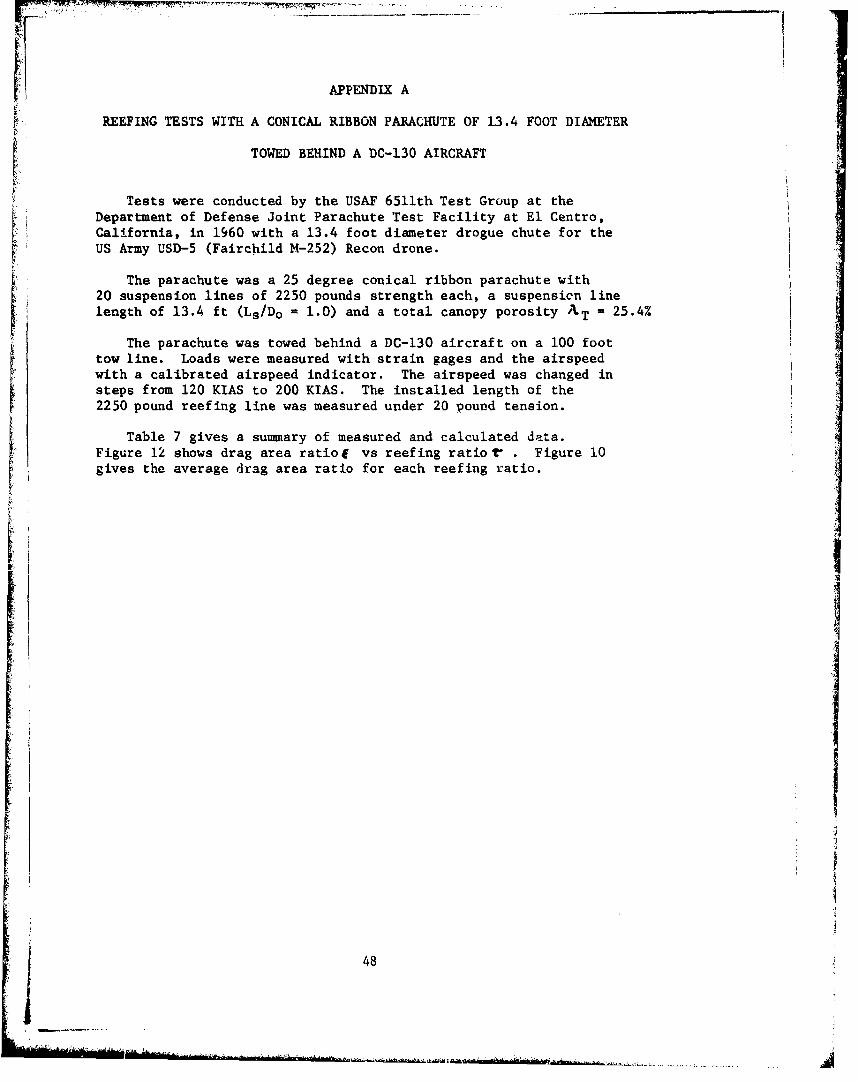
APPENDIX A Reefing Tests with a Conical Ribbon Parachute 48of 13.7 Ft Diameter Towed behind a DC-130Aircraft
APPENDIX B Reefing Tests with a 3.0 Ft Diameter Flat 49Ribbon Parachute foi the X-2 Research Aircraftin the Wright Field 20 Ft Massie MemorialWind Tunnel
REFERENCES 50
Precuding page blank
LIST OF ILLUSTRATIONS
Figure lave
1 Comparison of Skirt Reefing and Mid-Gore Reefing 21
2 Drag Area Ratio j vs Reefing Ratio r for Solid 22Circular Flat, Solid Conical, and TriconicalParachutes Larger than 15 Feet in Diameter
3 Drag Area Ratiol vs Reefing Ratio r for All Solid 23Circular Flit, Conical, and Triconical Parachutes
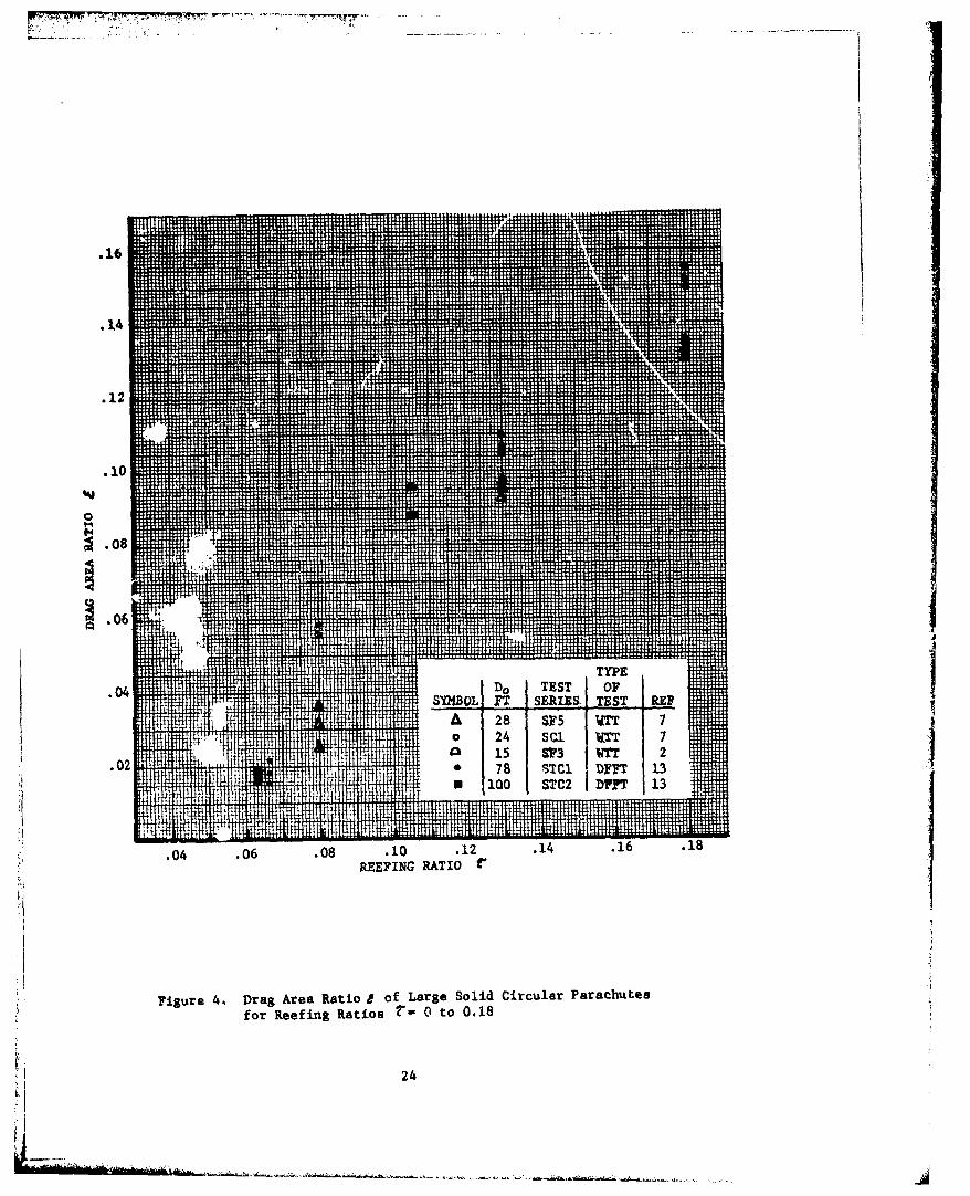
4 Drag Area Ratio& of Large Solid Circular 24Parachutes for Reefing Ratios r - 0 to 0.18
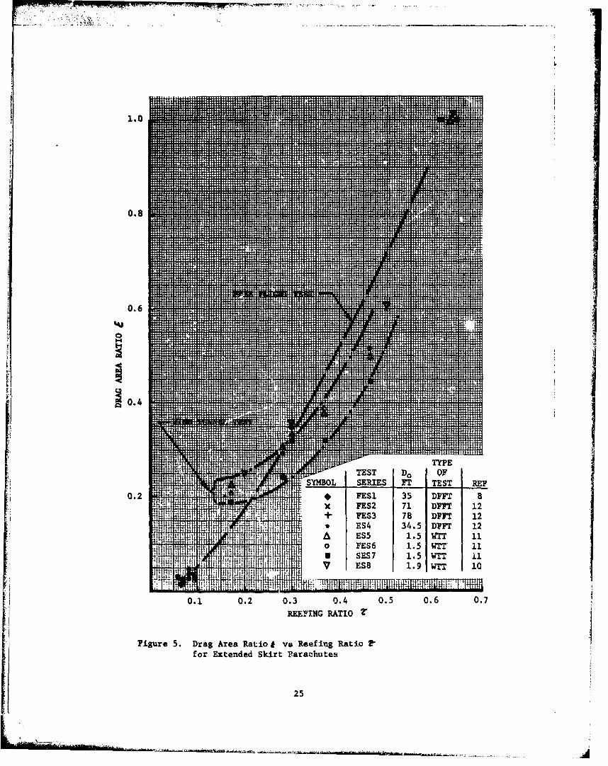
5 Drag Area Ratio 1 vs Reefing Ratio r for 25Extended Skirt Parachutes
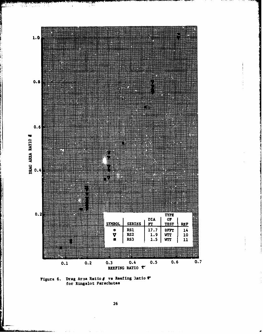
6 Drag Area Ratio I vs Reefing Ratio T for 26Ringslot Parachutes
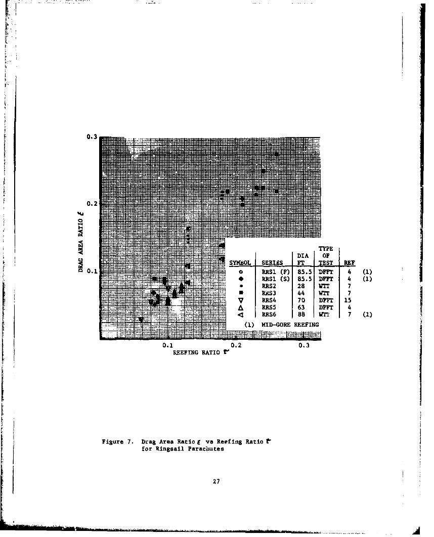
Drag Area Ratio I vs Reefing Ratio f for 27 IRingsail Parachutes
8 Comparison of Skirt Reefing and Mid-Gore 28Reefing for Ringsail Parachutes
9 Drag Area Ratio t vs Reefing Ratio r for 29Ribbon Parachutes
10 Drag Area Ratio f vs Reefing Ratio V for 304
12 Foot to 40 Foot Diameter RibbonParachute Series Tested at El Centro CA
11 Drag Area Ratio I vs Recf-ng Ratio t for Solid 31Circular, Extended Skirt. Ringslot, Ringsail,and Ribbon Parachutes (Summary Chart)
12 Drag Area Ratio E vs Reefing Ratio r for 3213.4 Foot Diameter Conical Ribbon
vi
"N. .... OF". ..... ,-- ,......
LIST OF TABLF-S
Table Pg
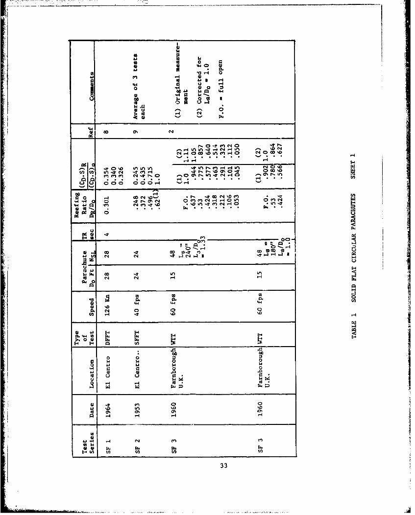
1 Solid Flat Circular Parachutes 33
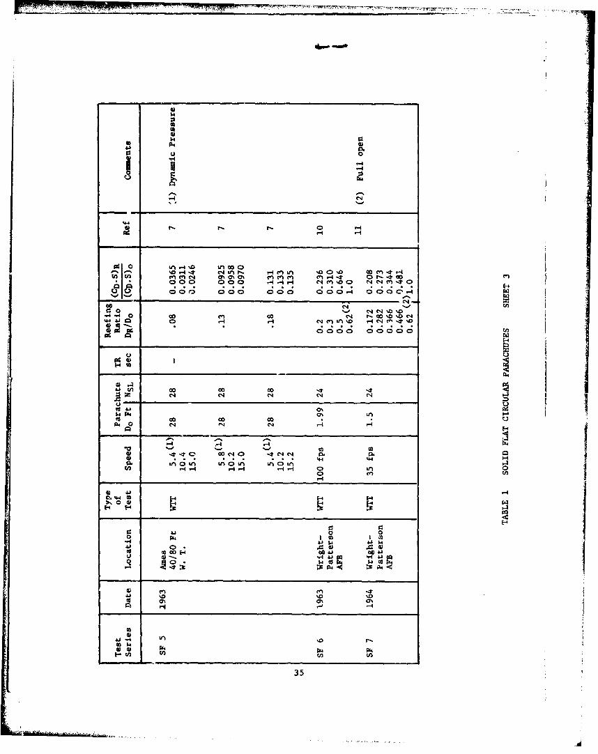
2 Solid Circular Conical Parachutes 36
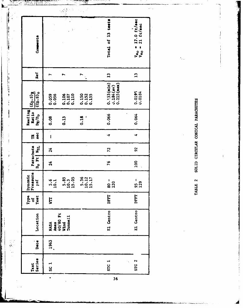
3 Extended Skirt Parachutes 37
4 Ringslot Parachutes 39
5 Ringsaii Parachutes 40
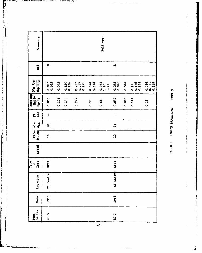
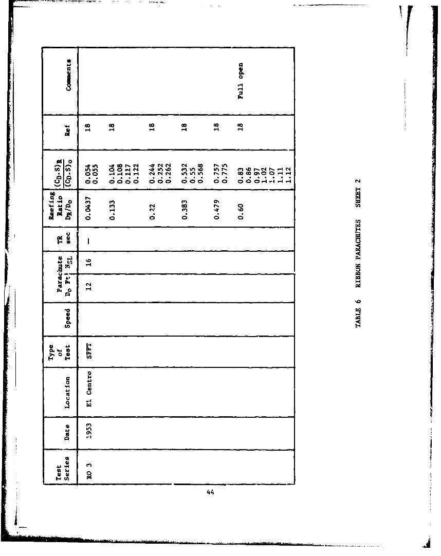
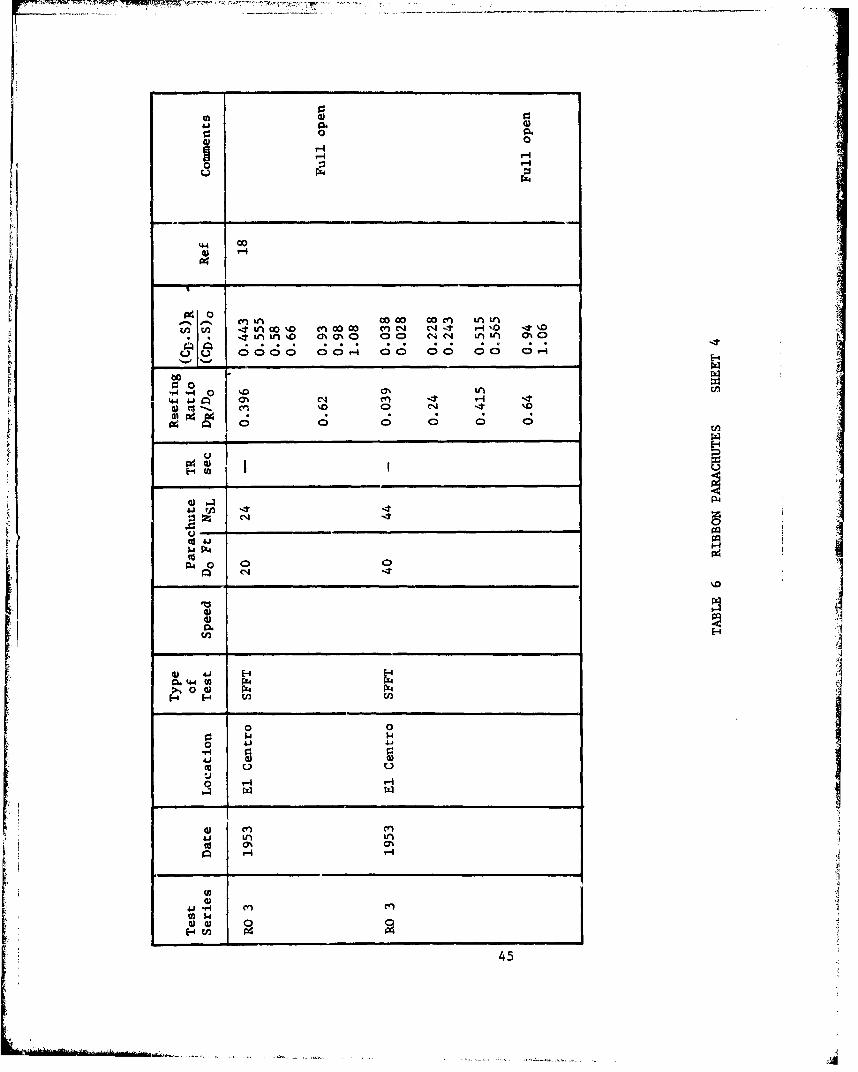
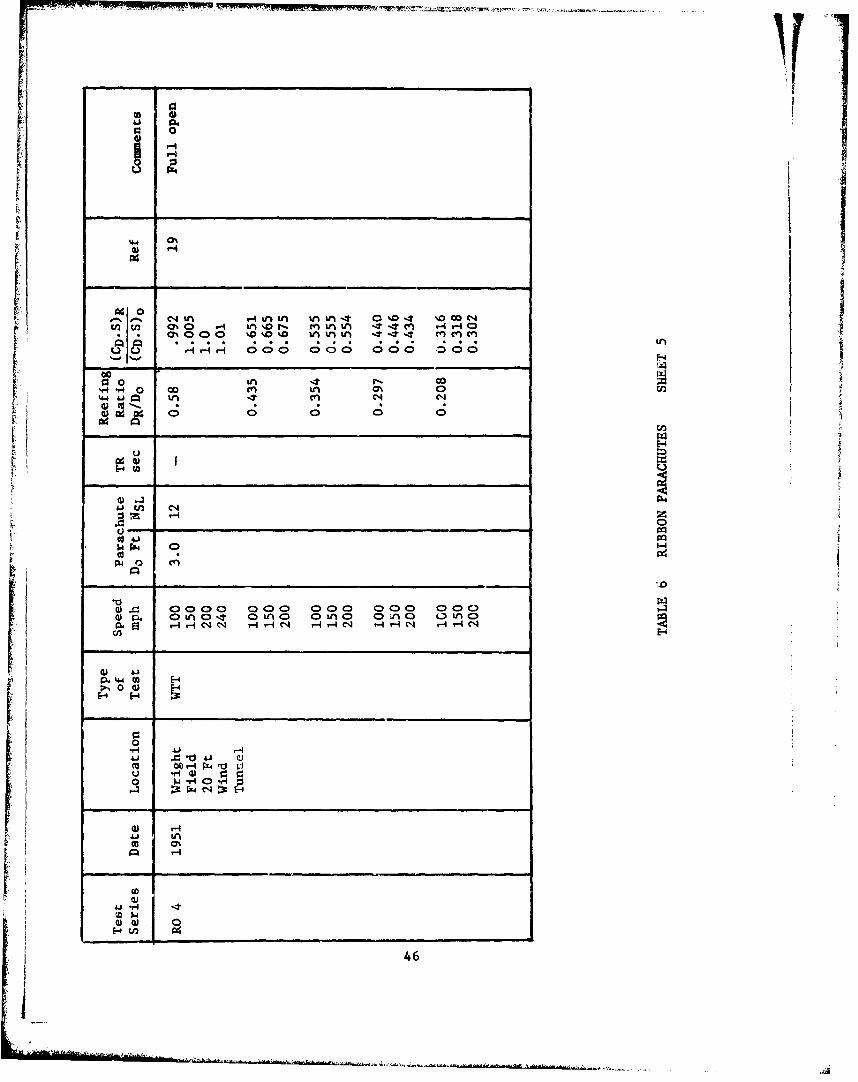
6 Ribbon Parachutes 42
vI
!I
vii
I+LIS: OF SYlMOLS
__bol Con.- apt Dimensions
CDo drag eoefficient of a parachute canopy based on nonesurface area So
CDR drag coefficient of a reefed parachute based on nore
surface area So
Do nominal diameter of parachute canopy, Do feet
DR diameter of a circle forsed by the reefing line feetin a reefed parachute canopy
DRo diameter of a circle formed by the reefing line feetof a full open parachute canopy (referencelength only)
LR installed length of a reefing line feet
LRo installed length of a reefing line of a full open teetparachute canopy (referenc length only)
NG number of gores in a parachute canopy none
NSL number of suspension lines of a parachute none
q dynamic pressure psf
So total one-sided surface area of a parachute ttýcanopy including vent and npenings of slottedcanopies
(CDS)o drag area of a full inflated parachute ft 2
(CDS)R drag area of a reefed parachute ft 2
C ratio between suspension liie circle of a full noneinflated parachute canopy (DK,) and nominal
parochute diameter Do
V velocity ft/sec
Veo sea level rate of descent ft/sec
angle of attack degrees
(CS)R - drag area ratio: ratio of reefed to none(-CS)o unreefed parachute drag area
density of air slugs/ft 3
S~DRDro° reefing ratio: ratio of reefing line circle none
diameter DR to nominal parachute diameter Do
viii
VA
SECOION I
INTRODUCTION
The purpose of this report is to summarize data on the reefingof parachutes, especially the :elationship of degree of reefing tothe resultant reduction in parachute drag area. Data have beencollected and analyzed for solid material parachutes of flatcircular and conical design, for various types of extended skirtparachutes, and for slotted parachutes of ribbon, ringslot andringsail design. Special emphasis was placed or obtaining reefingdata that have not been published previously or are not availablethrough the Defense Documentation Center (DDC).
Reefing methods investigated and reefing terminology used atvarious times in the past are discussed and evaluated.
Figures 2 to 10 give drag area ratios I versus reefing ratios rfor all previously mentioned parachutes. Figure 11 gives a summaryof all reefing data. All plotted data are listed individually intables 1 to 6 in a form that allows inclusion in the data bank ofthe USAF Flight Dynamics Laboratory.
Analysis and discussion of all data shows generally good agreementamong results obtained under related, controlled conditions. Thereare limitations on the size of model parachutes that provide reefingtest data applicable to full scale design. With few exceptions,out-of-line data can be traced to unusual test conditions, non-traceable designs, or to definition problems.
Recommendacions are made for a common reefing terminology.
S.. . . I
SECTION II
SYSTEMS AND DEFINITIONS
1. General
Reefing of parachites, to the beat knowledge of the author, wasapplied for the first time on ribbon parachutes in the summer of 1941.These parachutes were used for the approach and landing decelerationof German Ju 52 aircraft deployed in airborne landing operations (seeReference 1). The parachutes were reefed on landing approach and dis-reefed by pilot command at aircraft touchdown. The reefing systemused restricted the canopy skirt inlet area with short lines attachedon one side to each suspension line attachment point at the canopyskirt with the other end of the lines held in a disconnect di'Lmce inthe center of the canopy skirt. All lines were disconnected simul-taneously by pilot command through firing of a charge in the dis-connect device. This approach was soon replaced by the ".0irt Reefingwith Control Line Method"( 1 ) It was recojnized er-ly that reefingcould be used advantageously for limiting the opening shock load ofparachutes and for the stabilization of cargo containers dropped fromhigh altitude with the parachutes reefed during high speed descentand disreefed prior to landing. That reefing is necessary foruniform inflation of large parachutes dropped in clusters was notestablished until 1948, when the USAF started to develop clusterparachute descent systems for heavy military equipment.
In 1943, the author of this report conducted an extensive investi-gation of more than a dozen different reefing concepts. This includedseveral vent reefing methods, reefing concepts with lines placedaround the canopy, the canopy skirt, and around the suspension linesat various distances from the skirt, and reefing methcvds with partsof the canopy held iii a special bag. The most practical systemevolved was the "Skirt Reefing Method," very much in the form as itis used today.
ii IAnother investigation of various reefi:•g methods was conducted
in 1960 in Great Britain by Walters, Cobb and rjonnett.(2) Again,the skirt reefing method, called "Rigging Point Reefing" in Great Britain,emerged as the most practical system.
Some unpublished investigations of reefing methods were conductedby the NASA Langley Research Center and by the USAF at Wright-Patterson AFB,The "Mid-Gore Reefing" method, a modification of the skirt reefingsystem, evolved from one of these USAF investigations. Most likely,other methods have been tested of which the author has no knowledge.
Reefing of a parachute for application in a recovery system
generally starts with an analytical determination of the amount ofreefing required. Today this is accomplished in computer runs wherethe number of reefing stages, drag area reductions, and staging times
2
rr • •i .... -- - --.. . •r .. :
are determined dependent on such requireawnts as maximum ullovablesystem deceleration, load balance in reefing stages, and availablealtitude-time sequence. TL. second stop than involves the dimensioningof the reefing system. If skirt rofting is used it means the deter-mination of the installed length and strength of the reef ing line(s)and of such system components as reofing rings, reefing cutters, etc.As already stated, the primary purpose of this report is the presenta-tion of data for calculating the required length of the reefing line.Length of reefing line, as used in this report, means installedlength. One frequently hears the comments, "We do not have sufficientdata for determination of tas required reofing line length!" Thisis an incorrect statement, as the great amount of data oresented inthis report will show. Unfortunately, many data that are availablein company reports are not available to the technical comunity ingeneral. The two uot typical examples are the large amount ofreef ing data collected on the parachute systems for the Mercury,Gemini, and Apollo spacecrafts a&d on the parachute system for theB-1 aircraft crew module rQccvery system. The author has obtainedthese and other anpublishad reofing data '•t makes no claim of havingobtained all the data available in compan) or government agency files.Many data remain also incomplete or le.,cking in some vital details.
2. Reef ing Systems
This paragraph describes and analyz-s the most commonly usedreefing systems.
a. Skirt Reefing
Skirt reefing, by far the most commonly used form of reefins,is sufficiently known to make a detailed description unnecessary.'Figure L.a shows a view into the parachute caropy. Each confluencepoint of suspension line and canopy skirt has a reefing ring attached,with two or more reefing cutters located at several equally spacedpoints around the canopy. The diameter of the circle formed by theinstalled reefing line is defined as reeflng disaster,.DR. For
reliability reasons, tw. or more reeft-4g cut'ers are i~sed. This assuesthat the reefing line is cut even if one of the cutters fails to function.It may be of interest to mention that the Apollo main parachute systemused two reefin• lines and two reefing cutters per line in the firstreefing stage.(3) This assured proper functioning of the systemwithin prescribed reliability limits, in case one reefing cutter didnot fire, but also f.' the case that one reefing line was cut pre-maturely. The extr le high reliatility requirement of the Apolloparachute system, which was the primary means of earth landing forthe astronauts, made this complex appr-ach mandatory.
3
b. Mid-Gore Reefing
Mid-Gore reefing is a modification of skizt reefing developed
by the Parachute Branch of the USAF Aeronautical Systems Division atWright-Patterson AFB, Ohio. Figure l.b shows the arrangement lookiaginto the skirt of the parachute. The reefing rings are attached to theskirt of the parachute in the center of each gore instead of thesuspension line-canopy attachment points. This provides for doublethe restraining points, as can be seen from Figure i.b, and thus forless flutter of the uninflated parts of the reefed parachute canopy.The result is a more uniform inflation process and a more uniformreefed drag area of individual cluster parachutes. The unusualinflation characteristics of reefed Ringsail parachutes caused non-uniform inflation of the three Apollo main parachutes; mid-gorereefing was one of the means that improved uniform cluster inflation.To the best of the author's knowledge, the Apollo parachute systemso far is the only operational application of rid-gore reefing.
It was found that for the same length of installed reefing line -
that is, for the same reefing ratio - a slightly larger drag areawas obtained with mid-gore reefing than with skirt reefing. The onlydata available on mid-gore reefing were obtained on Ringsail para-chutes in the Apollo program, see Figure 8 and References 4 and 5.
c. Vent Reefing
Another reefing method that has found some application is
co"muonly called vent reefing. This concept attaches a centerline tothe inside of the canopy vent('); pulling this line in the directionof flight toward the confluence -'at of the suspension lines firstforms a half toroid and then turns the canopy inside out. Adjustingthe centerline at the level of the skirt results in an increase ininflated canopy d ameter and a concomitant increase in drag of approxi-mately 30 percent/I ) This phenomenon is used in the design ofthe Airfoil and Annular parachutes for obtaining high drag. Testswith parachutes, vent-reefed to a low drag area, which means withthe vent pulled way down, showed a high rate of undesirable flutter.It also was impossible to obtain drag area ratios of less thanapproximately 0.1 prior to a position where individual suspensionlines would flap over and entangle the parachute canopy.
Comment: The author is aware of numerous attempts to develop"Continuous Disreefing" systems and is cognizant of the "Schade"reefing system used for Hi-Glide steerable sport parachutes; however,he considers these systems beyond the scope of this report.
4
S j
Reefing Definitions
Several methods have been used in the pas'- for defining therelationship of reefing line length to drag area decrease. The firstmethod, described In Reference 1, is called the "1947 Method" forpurposes of definition.
An improved method was published in the second edition of the USAFParachute Handbook.( 6 ) In this report it is called the "DRl/DRo Method."The third method, called the "DR/Do Method," used most frequently inrecent years, is considered the simplest and most accurate method,and is, therefore, recommended for future use.
a. The 1947 Method
The 1947 Method used by the author in the first siunmary reporton reefing(l) was based on aerodynamic considerations due to thelimited number of reefing tests conducted prior to that time. Therequired known reefed drag area of a large parachute is used tocalculate the diameter of an unreefece small parachute having thesame drag area. The diameter of the suspension line circle (reefingline circle) of the full open small parachute can be calculatedusing a factor c which had been determined in wind tunnel tests.A small adjustment is then made for the difference of the reefingline diameter circle of the full open small parachute and thereefing line diameter circle of the large reefed parachute. Thisreasonably accurate but complex method was replaced in the secondedition of the USAF Parachute Handbook( 6 ) by the DRl/DRo method.
b. The DRl/DRo Method
The DRl/DRo method evolved from a series of reefing tests onribbon and solid flat parachutes conducted in the early 1950's at theDepartment of Defense El Centro Parachute Test Facility. The reefingline circle diameter of the full open parachute DRo was used asreference diameter for calculating the reefing line length. DRo mustbe calculated and varies with the type of parachute and the numberof suspension lines NSL of the individual parachute.
This method, simpler than the 1947 method, has the advantagethat it results in a reefing ratio of 1.0 for the full open para-chute, but it requires the knowledge of the ratio 4 of reefing linediameter DRo of the full inflated parachute to the nominal diameter Do.This introduces some inaccuracies.
It was only a question of time before the idea of using thenominal parachute diameter as reference diameter would be suggested.This approach is called the "DR/Do Method."
5
" The DR/Do Method
Using the nominal diameter Do as reference for the reefing line
length has several advantages. The length of the reefing line is dnter-mined by defining the ratio of the reefing line diameter circle to thenominal diameter of the parachute called the reefing ratio t . This
ratio can easily be obtained in wind tunnel or free-flight tests from
the known length of the installed reefing line, and thereby its reefing
line circle diameter, and from the known nominal diameter of the para-
chute. It has one disadvantage which is of a more theoretical nature:
the reefing ratio i for the full open parachute is less than 1.0 and
varies between 0.58 and 0.65, depending on the type of parachute andthe number of suspension lines used.
The DR/Do Method was recommended by DUD organizations,
companies, and individuals contacted in the preparation o:- this report.The following terms are used in the analysis part of this report:
Drag Area Ratio f - (CD • S)R - Reefed parachute drag area(CD • So) Full open parachute drag area
Reef ing Ratio • = DR = Diameter of reefing line circle
dee RMthod o Nominal parachute diameter
d. The CR Method
Some investigators have defined a reefed drag coefficient CR
and have used the parachute surface area So as reference area. (11, 17)
This definition agrees with the terminology used in testing drag and
lift bodies in wind tunnel tests; however, it is less convenient for
calculating reefing line dimensions. The reefing coefficient CR depends
on the indiviuual parachute tested and varies among parachutes of the
same type based on diameter, number of suspension lines, and porosity.
It varies even more between parachutes of different types; for example,
Ringsail and ribbon design; therefore, data cannot be used as ratios
which is the preferred and simplest approach for predetermination of
required reefed drag area. Plotting the data in the form of CDR/CDo,
as some authors have done, is equivalent to the dr,.g area ratio f
It produces the saMS results since both use the same reflyrence area So.
SECTION III
DRAG AREA RATIOS VS REEFING RATIOS
1. General Discussion
Reefing data have been collected and evaluated for the followingparachute types: solid circular parachutes of flat, conical, andtriconical design; extended skirt prrachute of 10 percent flat extended,14.3 percent full extended, and 10 percent straight extended designs;and slotted par.,chutes of flat and conical ribbon, ringslot, andRingsall designs. Data are shown as drag area ratio g vs reefing ratio rin Figures 2 to 11.
Some of these figures indicate a considerable spread Jn reefingdata. A closer examination shows, however, that the data spread isgenerally caused by parachutes too small in diameter to obtain validreefing data, design characteristics such as low or high canopyporosity, and other unusual design and testing approaches.
Analysis of parachute reefing used in var-ious recovery systemapplications shows a distinct difference between low rate of descentfinal recovery parachutes and first stage drogue and weapons retarda-tion and aircraft deceleration parachutes. The first group of parachutes.frequently referred to as low canopy loading W/CDS parachutes, is mostlyreefed to 5 to 10 percent or in the terminology of this report, toreefing ratios of 0.05 to 0.1; this includes solid flat, solid conical,and extended skirt parachutes; Ringsail parachutes with two-stagereefing frequently are reefed at ratios up to 0.25.
The second group of parachutes, with high canopy loading W/CDS,uses reefing ratios in the range of 0.2 to 0.5; these are normally
ribbon or ringslot parachutes.
Parachute reefing tests for a specific parachute, therefore, shouldinclude tests of the particular reefing ratio range used in full scalesystems applica 'in. Wind tunnel reefing tests with models of 1.5to 3.0 feet in d-m.veter will give acceptable results in the 0.2 to 0.5reefing ratio range. These small diameter parachutes, however, willcollapse or have poor inflation characteristics at reefing ratios ofless than 0.2. This means that reefing data can be obtained in windtunnel tests on small model parachutes used in full scale applicationas first stage drogue or weapons and aircraft deceleration parachutes,but not on low speed final descent type parachutes. The relativestiffness of the parachute material and seams prevents small modelparachutes from proper inflation at low reefing ratios.
7
• / • ,• . •_ _ _ _ _ _• : -.. .... .•• . . . . . ..... . .. . .... . ... ... . .. ... ... . . ... .
Some of the examined test reports do not clearly define if therea-fing line lev ;th is the installed length or the measured total length;often the tension (preload) is not stated umder which the line lengthwas measured. Small parachutes frequently suffer considerable shrinkagein the manufacturing process which can amount to 10 percent of thedesign surface area. It was not always clear if tbA quoted diameter wasthe drawing diameter or the manufactured (finished) iameter. Lack ofthis information can result in inaccurate data.
a. Test Methods
Data evaluated in this repurt were obtained: (a) in dynamic freeflight tests (parachute drop tests) where parachute forces andvelocities were recorded vs time by nreans of telemetry and phototheodolite, (b) in free flight tests with permanently reefed parachutesconducted for the purpose of obtaining reefed drag area data, and (c)in wind tunnel tests.
Dynamic free flight tests, (DFFT) in the tables and figures of thisreport, have the advantage that full scale parachutes are dropped reefed,then disreefed to descend fully open. This gives good reefed dragarea values if reefing times of four or more seconds are used. Shorterreefing times frequently do not allow the parachute to obtain goodstabilized reefed inflation. The result may be a lower drag area thanthat obtained in longer reefing times where the parachute had time todevelop its full inflated reefed diameter. Dynamic free flight testsfor full scale application generally cover reefing ratios of 0.05 to 0.1for final descent parachutes and reefing ratios of 0.2 to 0.5 for drogueand deceleration type parachutes.
Freefall tests (SFFT) of parachutes with long reefing times orfixed reefing are the ideal approach for this purpose. Unfortunately,they are, also the most expensive means of obtaining these data.
Wind tunnel tests (WTT) are most economical, are best cnntrolledand give results that are easily transferrable to full scale reefing ifa few ground rules are observed. Test results evaluated in this reportshow that final descent parachutes such as solid material and Ringsailparachutes should be at least 10 to 15 feet in diameter in order togive useful reefing data. Drogue chutes, expecially ribbon and ringslotparachutes, already obtain good reefing data with parachutes of 3 to 5feet in diameter because of the previously mentioned fact that lowreefing ratios are used for final descent parachutes and large reefingratios for drogue parachutes.
8
--- - -- -_ .
Wind tunnel tests also easily provide data over the total reefingrange. This is never done in dynamic free flight tests of parachutestested for systems application and seldom done in free fall tests ofreefed parachutes due to effort and funding lititations.
b. Presentation of Test Results
All individual data points are tabulated and plotted in order toallow the reader to make his own analysis of test results. If thedata point has been averaged from several tests, it is mentioned and
the source of the original data is given. Tables 1 to 6 give parachutedetails, test information, and test results. For data that are notavailable in reports the source of the data is given and actual testvalues are tabulated.
c. Abbreviations Used
Following abbreviations are used in the tables and figures forparachute types and test methods used:
SF - Solid _lat parachuteSC - Solid conical parachuteSTC - Solid triconical parachuteES - 10 percent flat extended skirt parachuteFES - Full (14.3%) extended skirt parachute
SES - 10 percent straight extended skirt parachuteRO - Flat ribbon parachuteRC - Conical ribbon parachuteRS - Ringslot parachuteRRS - Ringsail parachuteWTT - Wind tunnel testsSFFT - Free flight test with permanently reefed parachutesDFFT - Free flight test with tempo_'arily reefed parachutes
conducted for the purpose of obtaining load andsystems data
2. Solid Circular Parachutes
Figures 2, 3, and 4 give drag area ratios vs -eefing ratios foiflat, conical, and triconical solid circular parachutes. Figure 2 showsgood agreement of data obtained on large diameter parachutes in freeflight drop test (DFFT), in free fall reefing tests (SFFT), and in windtunnel tests (WTT). Figure 3, similar to Figure 2, also includes dataon small parachute models. Several changes are obvious: drag arearatios vs rcefing ratios obtained on small wind tunnel models varywidely from those obtained on large diameter parachutes. Large
9
parachutes can be reefed down to a ratio of 0.06 with a resultant dragarea ratio of 0.016 to 0.025 and still show a tube type inflation andno flutter (see parachute. SF5, STC1, and STC2 in Figures 2 and 3).Small parachutes of 1.5 to 2 feet diameter cannot be reefed to ratiosless than 0.15 to 0.2 with a resultant minimum drag area ratio ofapproximately 0.2 (see SF6 and SF7). The 15 foot and 8.? foot diameterparachutes (sr3, SF4) tested in British wind tunnel tests could bereefed to approximately a 0.1 ratio.
Data- on DFFT tests with large diameter parachutes were availablefor evaluation in the reef ing range from 0.06 to 0.1 and up to 0.25for Ringsail parachutes. Limited tests have been conducted with largeparachutes and higher reef ing ratios; however, these data were notavailable for inclusion in this report. To conduct free flight highreef ing ratio tests on large parachutes for the purpose of completingcurves is too expensive. The author recommends that each new para-chute type that may find systems application be tested through itsreef ing range in a large wind tunnel. These tests provide a goodunderstanding of reef ing and good data for the required reef ing ratiurange.
The following comments are in order for the analysis of dataobtained in free flight tests. With a short (2 seconds) reef ing time,parachutes seldom obtain a steady drag area. There generally is a dragarea overshoot at the beginning of the reef ed stage, then a decreasefollowed by a gradual increase. This is less uniform on solid materialthan on slotted canopies. Data obtained in wind tunnel tests are bynature more uniform. Free flight tests require a number of drops inorder to obtain a good average value. Errors or inaccuracies inmeasured values of speed and altitude obtained by photoilieodolite, inloads obtained by strain gages and telemetry, and in atmospheric con-ditions can result in notable variations.
Figure 4 shows that few good data are available in the reef ingratio range below 8 percent. Attempts by the author to obtain ucefulreef ing data on the C-11A and G-12 cargo parachutes were ansuccessful.Both parachutes are reef ed to ratios below 0.06; however., data werenever recorded in sufficient detail to permit the analyri~s requiredfor this report.
a. Discussion of Individual Parachute Tests
Table 1 lists data on solid flat parachutes tested, on testconditions, on drag area ratios vs reef ing ratios', and the source ofthese data.
Parachute Series SFI; Reference 8:
The Recovery and Crew Station Branch of the USAF Flight DynamicsLaboratory in 1964 conducted a series of tests with reef ed solid flatcircular and extended 3kirt parachutes at the DOD El Centro ParachuteTest Facility.
10
The solid flat parachute tested was a standard 28 footdiameter man-carrying type, reefed for 4 seconds, using a 550 poundreef ing line. The parachutes were dropped at speeds of 130 knotsfrom a C-130 aircraft flying at 6,000 feet a"titude. Velocity, loads,
r: altitude, trajectory angle, atmospheric densiLy, temperature, andhumidity were carefully measured; the author was furnished the testrecords. The quick opening 28 foot diameter solid flat parachuteproduced a (CdS) overshoot in the beginning of the reefed phase andincreased the (CdS) sooner than would be expected from the 4 secondsreefing time. This may be caused by the smoothing technique usedin the determination of phototheodolite velocity data. A carefulanalysis conducted during the Apollo parachute test program determinedthr.t this smoothing technique could result in recorded dynamic pressureerrors of as much as 10 percent at the start and the end of thereefing period; this had a definite effect on the calculated CdS values.A 2-second track in the middle of the 4-second reefing time, thereforewas selected for analysis of these tests with readouts available forevery one-hundreth of a second. Despite considerable fluctuation ofthe measured CdS vs time, the average values for the 2-second periodwere relatively uniform as shown in Table I and Figures 2 and 3.
Parachute Series SF2; Reference 9:
The author had access to the results to unpublished reefing testsconducted in 1953 at the El Centro Parachute Test Facility withpermanently reefed 24 foot diameter T-10 reserve parachutes, seeSF2 in Table 1. The rate of descent in these tests was obtained withthe drop line metbod and the drag area calculated from the known rateof descent, parachute dimensions, drop weight, and atmospheric data.
Tests were Derfo-ed with: (a) the parachute tied togetner at theskirt: (b) the shortest possible reefing line; and (c) with reefingratios DR1/1Ro of 0.4, 0.6, 0.8; and full open. The parachute tiedclosed at the skirt would not inflate but descended stable with theI' canopy waving in a snake-like fashion; this canopy had a drag arearatio of approximately 0.015.
Tying the shortest possible line through the reefing ringsproduced a tube-like inflation with no flutter and a drag area ratioof approximately 0.025. These results agree well with data obtainedon a 28 foot diameter parachute(SF5) tested reefed in the Ames 40/80foot wind tunnel which had a minimum drag area ratio of 0.025.(7)
Parachute Series SF3 and SF4; Reference 2:
In 1960, in Fainborough, England, M.H.L. Waters ant Associatesconducted wind tunnel tests on parachute reefing. The parachutestested included numerous British designs and solid flat and solidconical models of 8.7 feet and 15 feet diameter. These tests are ofparticular interest because they include tests with parachutes ofthree different suspension line lengths, LSiDo = 1.33, 1.0, and 0.67,
11
variation in material porosity, anu in number of suspension lines fortht same parachute diameter. Suspsnsion lines longer than LS/Do 1.0are used frequently for drogue chutes and cluster main parachutessubstituting required riser length with longer parachute suspensionlines which result in an up to 10 percent increase in drag withoutan increase in parachute weight.
The British authors use as reference tor the calculation of reefingand drag area ratios the values obtained for the full open parachutewith the line ratio Ls/Do - 1.33. This report uees the data obtainedwith the full open parachute with a mine ratio Ls/Do of 1.0 asreference. For most applications, parachutes with this line ratiowill be the starting point for systems design. The difference indrag area ratio for the same reefing ratio due to line length isneglectable at small reefing ratios, see Figure 3. For large reefingratios, an Increase in drag area occurs for the parachutes with longsuspension lines and a decrease for the parachute& with short sus-pension lines.
Testq included a 15 foot solid flat canopy with 1/3 of the standardporosity. This parachute had a higher drag area ratio at low reefingratios than other solid flat parachutes, most likely due to a largerinflated reefed diameter at low reefing ratios.
Paracaute Series SF5; Reference 7:
Tests were conducted in 1963 with Apollo parachutes in the NASAAmes Research Center 40 by 80 foct wind tunnel. The prime purpose wasto investigate inflation characteristics of various Ringsail para-chute designs. Included in these tests were a 28 foot diameter solidflat circular, a 24 foot diameter solid circular conical, and a32 foot diameter solid hemispherical parachute.( 5 , 7) Tests wereconducted at reefing tatios of 0.08, 0.13, 0.13 at dynamic pressuresof 5, 10, and 15 psf. Results obtained with the 28 foot 4li&etersolid circular flat narachute are I'sted under SF5 in Table 1 andFigures 2, 3, and 4. The -ults of these wind tunnel testb agreevery well with reefing data obtained in free flight tests.
Parachute Series SF6 an SF7; References 10 and 11:
In 1963 and 1964, the USAF, at Wright-Patterson AFB, conducted twoparachute wind tunnel progiama of (a) pavr'.bute clusters, and (b) theinvestigation of drag and st&ab1lty of v&rlouE. parachute types(10, 11)Both programs included tests with refed parachutes covering thereefing range from minimum possible to full open. These tests withparachutes of 1.5 and 2 0 feet in dianeter gave good results in theprime areas of investig,.Aon, namely, parachute clustering, staticstability, and full open performarce. The data on parachute reefingwere, however, subject to the previously mentioned limitations, thatof size. The relatively high stiffnes- of the small parachutes makebit impossible to reef to low ratios and changes reefing data in themedium reefing range.
12
Parac}iute Serits SCl; Reference 7:
Today solid conical parachute types are used in preference tosolid flat parachutes as final demcent parachutes. Only one testseries could be found, however, that provided reliable reefinginformation on ...ra1<. "lid conical parachutes. Tests with A
24 foot diameter conical parachute wiere part of the Apollo parachutewind tunnel test program in the NASA Ames AO by 80 foot wind tunnel.The drag area ratios, listed in Table 2 and shown in Figures 2 and 4,appear to be slightly higher than those obtained on solid flatparachutes. Several agencies and individuals contacted expressed theopinion that little difference seems to exist between the reefing ofsolid circular ilat and solid circular conical parachutes.
Parachute Series STC1 and STC2; Reference 13:
The Pioneer Parachute Company has developed a series of "Tri-conical" solid circular parachutes. Data were provided by J. Reutherfrom Pioneer on free flight drop tests of reefed 76 foot diameter andreefed 100 foot diameter parachutes. Numerous tevts were conductedwith both parachutes, but with one reefing ratio only. The 100 footdiameter parachute was dropped with test weights of 2200 pounds and3600 pounds, resulting in canopy loadings W/S of 0.255 and 0.458 psf,and rates of descent of 17 and 21 ft/sec. Drag areas of 150 ft 2 and130 ft 2 , respectively, were obtained for the same reefirg ratio withthe two canopy loadings, see Table 2 and Figures 2, 3, and 4. Itappears that the higher canopy loading produced a slightly smallerinflated reefed diameter.
:f 3. Extended Skirt Parachutes:
Reefing data have been obtained on three types of extended skirtparachutes: on a 10 percent flat extended skirt design (ES), on a10 percent straight extended skirt design (SES), and on a 14.3 percentfull extended skirt design (FES). Eight different groups of reefingtests were evaluated. Four of these test series are free flighttests (DFFT) on parachutes from 28 feet to 78 feet in diameter; theremaining four are wind tunnel tests using 1.5 foot diameter and1.9 foot diameter parachutes. The results are similar to thoseobtained with solid circular parachutes. All ftee fliglt tests usereefing ratios of 0.05 to 0.10 with corresponding drag area ratiosof 0.02 to 0.05.
Test series ESI was conducted as a research project using a reefingratio of 0.3 similar to the solid circular SFI test series.
The small diameter wind tunnel models behaved 31milar .o the smallsolid Zlat circular models. Reefing ratios below 0.17 could not beobtained due to collapre of the relatively stiff parachute canopy.
13
There is no ý,",%ervable difference in the drPg area ratio vsreefing ratio amo- the three types of extended skirt parachutes. Adetaile examination of Reference 12 shows that the 34.5 ft diameter10 perceut extended skirt parachute developed as descent parachutefor the B-70 encapsulated seat, had a slightly higher drag area forthe same reefing ratio. As the report points out, however, this para-chute was designed for fast inflation, a characteristic that generallyresults in high drag area ratios.
A direct comparison of solid flt and extended skirt parachutes(See Figure 11) shows that for the same reefing ratios both havepractically identical drag area ratios.
Details of all tested parachutes including referetices are listedIn Table 3. Resultant reefing and drag area ratios are shown inFigure 5.
4. Ringslot Parachutes
Few 4ata are available on reefed ringslot parachutes. A 17.7 ftdiameter reefed ringslot parachute was developed by Northrop in 1964as final descent parachute for a reentry body with a water entryvelocity of 50 ft/sec. This parachute, reefed in one step, was testedat speeds up to 360 knots. (14) The data are recorded in Table 4 asRSI. The two USAF wind tunnel test programs for the investigation cfcluster parachutes and the static stability characteristics of para-chutes include reefed ringslot parachutes. (10, 11)
The results of the free flight parachute tests and tests with tsmall wind tunnel models are listed in Table 4 and it. Figure 6. Thewind tunnel test data on the small parachutes RS2 and RS3 are stillsomewhat higher than the results of the freeflight tests with thelarger parachutes. The difference is not nearly as pronounced however,as on solid circular and extended skirt parachutes.
An interesting reefing program was conducted in 1954 by the USAF6511th Test Group in El Centro, California with a 34 ft diameterringslot parachute developed for a 500 lb. U.S. Marine aerial resupply,:ontainer. It was obv.rved that the parachute, at test speeds 1'r to500 knots, wold open into the reefed position by stepwise inflation ofthe concentric rings forming the canopy; the opening process alsoappeared to be velocity sensitive. The reefing line was then eliminatedand a large circumferential slot introduced into the canopy located atthe leading edge of the inflated reefed canopy area. As result of thischange, the parachute would open but stop inflating as soon as itreached the large slot. The canopy inflated fully, independent of dropspeed, as soon as the velocity decreased to approximately 100 knots.
14
j1

All tests were conductea with parachutes made by the same manufacturerfrom the same lot of canopy material with the test results reasonablyuniform. Whether this phenomenon can be utilized in operationalarplication is uncertain if one considers the allowable material poros-ity variation and tolerances in the manfacture of parachutes. Asimilar behavior, the step by step opening of individual rings, waslater experienced on the large RingsaIl parachutes used for spacevehicle recovery.
5. Ringsail Parachutes
The determination of the reefed drag area of Ringsail parachutcsis more complex than for other parachutes because Ringsail parechutesopen in steps and grow during reefed op iing. The reefed 88 footdiameter main parachutes for the Apollo I command module would openquickly to the fourth ring, thereafter a slow stepwise inflation wouldoccur until the growth stopped with the seventh ring semi-inflated.This process took several seconds. Growth in the reefed drag area isa distinct advantage for single main parachutes as used for the Mercuryand Gemini space capsules. It creited a major problem on the clusterof three Apollo main parachutes. One or two of the parachunes would bein a "lead" position at reefed inflation, grow faster, and obtain anearlier full inflation after disreef. This led to overload and damagein the lead parachute(s). An extensive wind tunnel test program wasconducted ~in the NASA Ames 40 by 80 foot wind tunnel using full scale,one-half scale, and one-third scale parachutes. The primary purposeof these tests was to investigate the Riagsail parachute inflationprocess aimed at obtaining a more uniform cluster opening. A secondaryobjective was to obtain data on the reefing of Ringsail parachutes.( 5 v 7)The full scale 88 foot diameter Apollo I parachute and the one-halfscale version were only tested in the reefed configuration. The smallscale, 28 foot diameter Ringsail parachute was tested reefed and fullopen.
Modifying the 88 foot diameter Apollo I parachute with a circum-ferential slot equal in width to 75 percent of the fifth ring greatlyimproved uniform inflation of the three parachutes. The slot stoppedthe reefed inflation at the fifth ring and allowed the lag parachute(s)to catch up before disreefing occurred.
All reefed Ringsail parachute data are listed in Table 3 and shownin Figures 7 and 8.
Configuration RRSI shows the drag area vs reefing ratio for thetwo reefing stages of the final 85 foot diameter Apollo main parachutes.Even the parachute modified with the slot at the fifth ring had amodest amount of growth; this can be seen from the difference betweenthe initial reefed drag area and the drag area at disreef in both thefirst and second reefing stages, see columns (F) and (D) in Table 5.
15
Wind tunnel tests with reefed Ringsail parachutes will give highdrag area values because the parachutes have obtained their reefedfull inflated position. This occurs seldom in free flight tests dueto limited reefing times.
Daca were provided by the USAF/ASD B-1 SPO on reefing the clusterof three each 70 foot diameter Ringsail main parachutes for the B-1crew module.(15) These testo, shown as RRS4, confirm that dataobtained in free flight tests are somewhat lower than data obtainedin wind tunnel tests for the aforementioned growth reasons.
The data in Figure 7 show the high values for the wind tunneltest models, RRS2, RRS3, and RRS6, and the somewhat lower values forthe free flight tests RRSl, RRS4, and RRS5.
Figure 8 compares data on Apollo parachutes with skirt reefingand mid-gore reefing. The only direct comoarisons were obtained inthe Ames wind tunnel tests with a single ,•pollo I parachute of88 feet diameter tested with both types of reefing. Comparing the85 foot diameter final Apollo II parachutes with mid-gore reefing withthe 70 foot diameter B-i parachutes with skirt reefing confirms thehigher drag area ratios for the Apollo parachutes with mid-gorereefing. Additional Rin sail reefing data can be found in the RingsailParachute Design report.14)
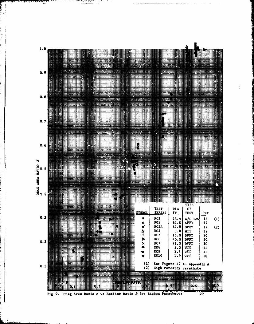
6. Ribbon Parachutes
More reefing data are available on ribbon parachutes than on anyother parachute type. Ribbon parachutes are used primarily for thrieapplications: first stage drogue parachutes for missile and dronerecovery, weapons retardation parachutes, and aircraft decelerationparachutes. All three applications require a rather precise knowledgeof the aerodynamic characteristics of the decelerator. Drogue chutesare relatively small and can easily be tested in the wind tunnel. Theinitial application to weapons made the acquisition of good reefingdata mandatory. In addition, most of these projects were handled bygovernment agencies, which made it easier to plan and execute aeriala, -ell as wind tunnel tests. Data covering the total reefing ratiorange were obtained with large and small ribbon parachutes in windtunnel, free flight, and aircraft tow tests.
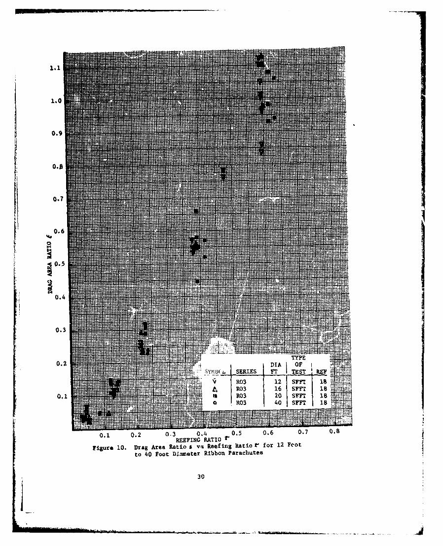
The investigated parachutes are listed in Table 6. Drag arearatios vs reefing ratios are shown in Figures 9 and 10. Appendices Aand B provide unpublished data on two test programs on reefing ofribbon parachutes.
A large series of reefing tests were conducted at El Centro from
1952 tc 1954. The results of these special tests are plottedseparately in Pgure 10 so as not to make summary Figure 9 illegible.All data show reletively good agreement.
16
Individual Test Results
Parachute Series RC1; Appenrdx A:
The US Army USD-5 re.connaissance drone used a 13.4 foot diameter25-degree conical ribbon parachute as first stage drogue chute duringthe R&D phase. The USAF 6511th Test Group at El Centro conducted aseries of reefing tests towing this parachute behind a C-130 aircraft.Since the parachute was rested in six reeftug steps from 0.075 reefingrarto to full open with the airspeed varying from 120 knots to 200knots, the aircraft tow speed had to he reduced with increasingparachute drag area in order to maintain good C--130 flying conditions.Most reefing ratios were tested over the increasing and the decreasingspeed range. The absolute values were approximately 5 percent lowdue to the wake effect behind the aircraft; however, reefing and diagarea ratios related to the full open towed parachute are consideredreliable. Details of the parachuti, the test procedure, and testresults are contained in Appendix A of this report.( 1 6 )
Parachute Series R02 and RO2A; Reference 17:
A heavy-duty, 64 foot dJameter ribbon parachute with 1000 poundhorizontal ribbons, 84 gores, and 6000 pound ouspension lines wastested at El Centro in 1953 in reefed free-fall tests. The rate ofdescent and the resultant drag area were determined by the drop iU,emethod measuring the rate of descent for the last 300 feet. Thisseemingly crude method, however, yielded good results. The parachutewas tested in two versions. The original porosity of close to20 percent (R02 A) resulted in a sloppy, slow tube type inflation withlow drag areas. A 28 foot standard man-carrying canopy then was
inserted in the vent area which reduced the porosity to 14.5 percent.The resultant bulb-like inflation caused high drag area ratios ascan be seen in Figure 9. Data for this parachute were taken fromReference 17 and original test data in the possession of the author.
Parachute Series R03; Reference 18:
A large test program with reefed ribbon parachutes was conduct2din 1952 at the El Centro Parachute Test Facility. These tests cove-a complete series of reefing tests using 12, 16, 20, and 40 footdiameter flat ribbon parachutes of heavy construction (500 and 1000pound horizontal ribbons and b000 pound suspension lines). Reference 18summarizes these tests; additional data were obtaine-d from the filesof the author. Each individual test is tabulated in Table 6 andplotted in Figure 10.
Parachute Ser4Žs R04; Reference 19:
In 1950, a heavy design 3.0 fiot diameter flat ribbon parachutewas tested in the Wright Field Vlassie Memorial 20 foot wind tunnel.These tests were part of a program tG develop a stabilization anddeceleration parachute for the pilot escape nose section of the X-2
17
'IA
I:
research aircraft. The parachute was tested with and without forebodyat reefing ratios from 0.208 to full open and speeds from 100 mph to250 mph. The data of these, tests, plotted in Figure 9, agree well withother test results. Appendix B of this reporr gives details of thisprogram.
Parachute Series RC5, RC6, and RC7; Reference 20-21:
The Sandia Laboratories in Albuquerque have tested reefed ribbonparachutes over a wide range of diameters, test vehicles, and speeds.Included in this report are reefing tests with 16, 40, and 76 footdiameter heavy-duty ribbon parachutes. The data were obtained infree-flight tests with velocities and position measured by Contravesphototheodolite cameras. The referenced data are not tabulated butplotted directly in Figure 9 under RC5, RC6, and RC7. The data forthe 16 and 40 foot diameter parachutes agree well with other testresults. The reefed drag area of the 76 foot diameter parachute islow over the total tested range. No explanation could be found forthis anomaly, except that the porosity of this parachute was relativelyhigh. All parachutes were of 20 degree conical design. It should alsobe noted that Sandia Labs does not use the nominal diameter Do, butthe diameter of the base of the canopy cone as reference diameter;this establishes the relationship DSandia - Do/i-033.
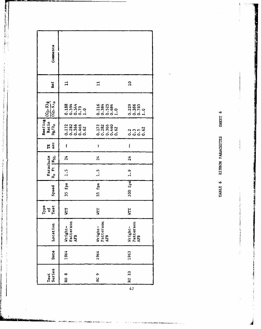
Parachute Series ROB and RC9M; Reference 11:
A 1.5 foot diameter flat and a 1.5 foot diameter 20 degree conicalribbon parachute were included in the test series in the Wright Field1 meter wind tunnel.( 1 1 ) The test range covered reefing ratios from0.2 to full open. Table 6, sheet 6, and Figure 9 show that the reefeddrag areas obtained in this reefing ratio range agree well with dataobtained on large parachutes in free-flight tests.
Parachute Series R010; Reference 10:
A single 1.9 foot diameter flat ribbon parachute was included inthe investigati.n of clustered parachutes conducted in the Wright Fieldwind tunnel. The results are shown in Table 6, sheet 6, and inFigure 9. Again, as it, the previous test series, there is good agree-ment with test data QThtained on large parachutes.
Evaluation of the reLIed 16.5 foot diameter conical ribbon drogueparachute for the Apollo II Command Mcdule shows good agreement withdata listed so far; no detailed data presentation was therefore made. (22)
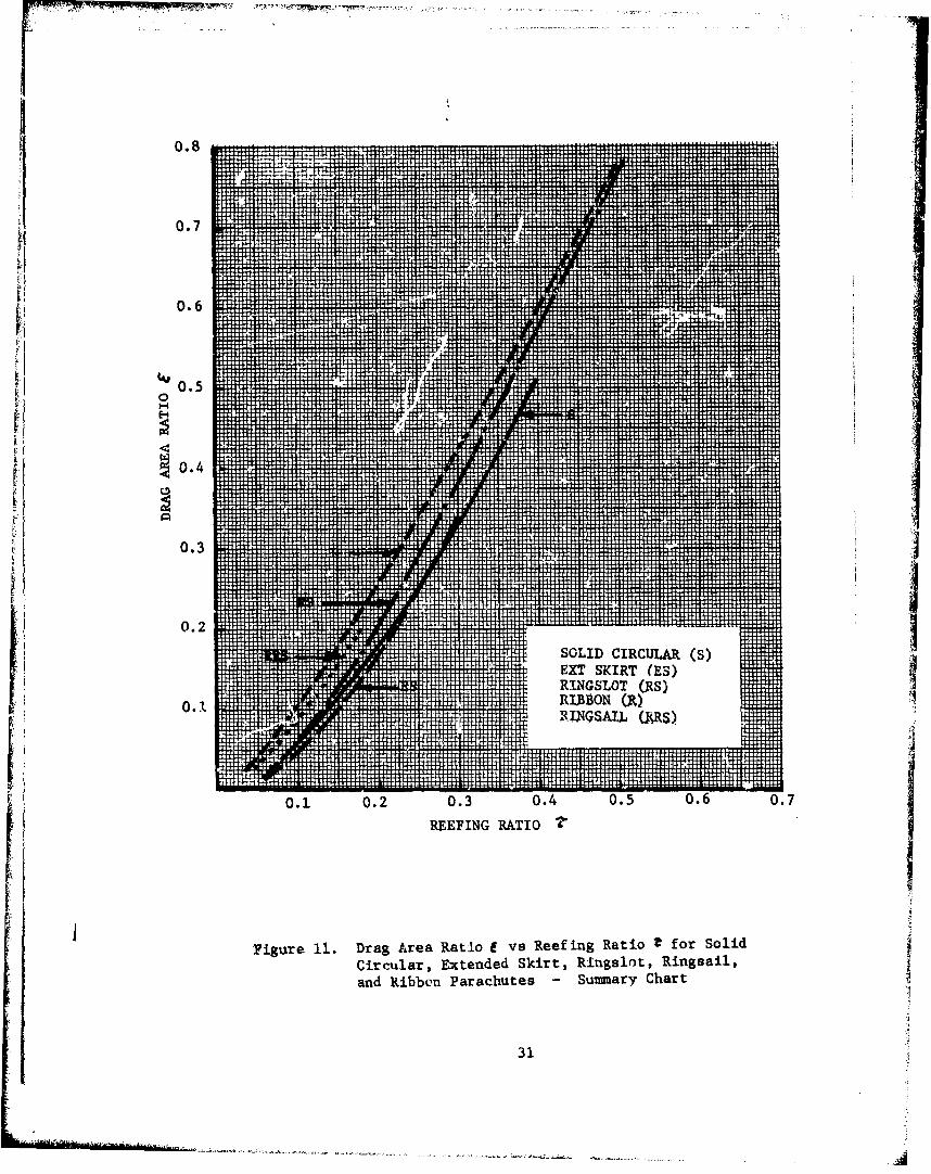
7. Summary
Average drag area ratio vs reefing ratio data for 'olid circular,extended skirt, ringslot, Ringsail, and ribbon parachutes have beencalculated and plotted in Figure 11. The average data for the solid
18
circular and extended skirt parachutes are almost identical consider-ing the normal variations in test results. One should also rememberthat reefing ratiou above 0.1 are seldom used on final recoveryparachutes that descend with velocities in the 15 to 35 ft/sec range.
The reefed drag area values for slotted parachutes are notablyhigher than for solid material parachutes. This can not be relatedto inflated diameter. In fact, Reference 11 shows that ribbon,ringslot, and Ringsail parachutes have smaller inflated diameters forthe same reefing ratio than solid material and extended skirt para-chutes. A possible explanation appeared in tests with reefed para-chutes In the Apollo NASA Ames wind tunnel. These tests showed astrong outward directed turbulent air flow through the slots of Ring-sail parachutes. This factor could cause the turbulent area aroundý-lotted canopies to be relatively larger than the turbulent area ofsolid material parachutes.
The data on ringslot parachutes at low reefing ratios are basedon only one series of free-flight tests. Wind tunnel tests on smallparachutes indicate the average values to be similar to those ofribbon parachutes.
The average drag area values for Ringsail parachutes have onlycomparison value due to the variation of reefed drag a,.aa with time.It can be stated however, that the drag area ratio values for thesame reefing ratio are close to those shown for rib',on parachuteswhich means the Ringsail parachute beheves similarly to the otherslotted parachute types.
Iif
19
AZ!
SECTION IV
CONCLUSIONS AND RECOMMENDiiiIONS
1. A wealth of reefing data is available on solid flat, solidconical, extended skirt, and ribbon parachutes. Any additional generalreefing tests on parachutes of this type are considered of little valueby the author.
2. Few data are available on ringslot parachutes in the low reefingratio range and on Ringsail parachutes in the higher reefing ratio range.
3. Final descent parachutes of solid flat, solid conical and extendedskirt designs are normally reefed to ratios of .05 to .10 and in specialcases up to .25. Tests with small diameter parachutes of these typesdo not provide useful data at these low reefing ratios due to poorreefed inflation. Reefing tests with final descent parachutes should beconducted with parachutes with a minimum size of 10 to 15 feet indiameter.
4. High canopy loading drogue or deceleration parachutes, such as ribbonand ringslot parachutes, use reefing ratios of 0.2 to 0.5. This is areefing range where parachutes with only 2 to 3 feet in diameter already !provide useful data,
5. Differences in suspension line length, number of gores, and canopyporosity cause variations in the drag area ratio for the same reefingratio. These variations are generally small for low reefing ratios butincrease with larger reefing ratios.
from the average value. If reefing data with a higher accuracy are
required, reefing tests must be conducted with that particular parachutefor fine-tunning of the reefing system.
7. It is advisable to conduct reefing tests in a large wind tunnel withany new parachute design that may find wide application. Parachutesize and wind tunnel required depend on the utilization of this newdesign as final descent parachute or drogue parachute.
8. Besides drag area vs reefing ratio data, loads in the reefing lineare required for proper selection of the reefing system. It isrecommended that this investigation be extended to an analysis of alldata obtained on reefing line forces.
20

~A
RE•EFING LINE B_
(a) SKIRT REEFING (b) MID-GORE REEFING
A - REEFING RING
B - SUSPENSION LINE ATTACHMENT POINT
Figure 1. Comparison of Skirt Reefing and Mid-Gore Reefing
21
0.11
CaI1iCIT 8
22T15~2 Feet iuVjWeTtD
1.0
.7
~ ,4
.3 __
HIJFIN RATOL CT SRE TS E+ 28 SF1 FFTIx 24 SV2 FFT
.2ur 3. Dra Area Rati 2 sRe u aioC o l oiCircular~ ~ Flat Concal and Tr2nclPrcue
. . . .. .. .2235 T
.16
.14
.12
.06 L.0 06 08 .1 .1 .1 .16. .18.
Figur 4. Drag AraRto*oOLreSldCrclrPrcue
for~2 Reeis Ratio 70to01
244i T
'IT15 S3 T78 SC IVT 1
01.8
0.6
~0.24E1 35 DF
SYBL SRES 34. TEST 12F
I tt v S -9WT 1
0.1 0.2 0.3 0.4 0.5 0.6 0.7
REEFING RATIO 2
Figure 5. Drag Area Ratio * vs Reefinug Ratio 2'f or Extended Skirt Parachutes
25
1.0
'0i8
0.44
0.1 0.T030.P.5 06E.
D I A O F
0.2
-SflWSOL SERILS FT TEST REF0. RRS1 (F) 85.5 DFPI 4 (1
V RRS4 70 DIP? 15
- 4 RRS6 88 irn 7 (1
0.1 0.2 0.3REEPING RATIO V'
Figure 7. Drag Area Ratiol vs Reefinig RatiotV for Ringsail Parachutes
27

0.2
o RRS1 85 DFFT 7 (1)
* RRSI 85 DFFT 4 (1)
V RRS4 70 DFFT! 15
(1)IN MAI D-OR REFN(2VKR EFN
Figure 8. Comparison of Skirt Reef ing and Mid-GoreReef ing of Ringsail Parachutes
28
1.01
0.9 
0.81
0.7 '
.... .... ... .... ...
0.6
~0.4 ...
0.3
0.234A/ o% 1
R006. 1.T 1E l 02 64.0 iF 1 2Fig9.Dra Aea ato vaRef Rtiot or Ribbo Paaht.0 T 29
+zt~ -C 1-0DT 2
0.6
0.1
0.4
0.30
................................................
0 .8.. .... ......
0.7
0.6
0.5
0O.4
F0.3 .. .
0.2 IBO
IT T0.1 0.2 0.3 0.4 0.5 0.60.
REEFING RATIO
Figure 11. Drag Area Ratio e vs Reef ing Ratio t for SolidCircular, Extended Skirt, Ringalot, Ringsail,and Ribbon Parachutes -Sunmnary Chart
31
1.0
0 .9-------- ------ -
0.8
0.7
'40.
00..3.304 05 . .
0.32
Iw
*0 a
*u *04 4'0 "4 4)0
0 -H 93 w --
60 04 I0a -
40 '.4 O
od E-
M en m ' (1 4N %r n 4Ný %f.
21 OD 4 %00 ' -400C14v-0 NOCOW
44 4J 4 n -Tf0 ,-n CA 4 ,4 0 - ~'Tfs
a M . - * .D
AU W 000 C4 .- -.1 4 14 a .4 -'
04 0 4-ON0 '.4-Of
.440 __ _ _ __ _ _ _ __ _ _ _ o->1 0 -
Lw 14 0 4
44 0. 0.
M '0 UC
0 o40 04 0d::04 P0
41 Un Co 0
(d ON. a% a%.
W'.W
33

) 10 091 0 540
* 4 4 ~ 4C4s
H C14
Hn C*4 00 4C
C41 C4-4 n-41 a000 c % 4 n 4
%0 sd n N '~ -I(4 r44
(D co00' c 0C- 0 0a0 0 0 0 -4
C:' 0'44 j 0 3C'J"%Oen I co -OC14 %0 cn
1-1 (44 .t-0 U 0C (J ou m (' 1 n C4 (l -t '
0 0
41 0s..0H Woo LO0 HN
w 44.
0. 0. W..000.40
di 4'44 4-4 44 -44 44 44 44 444"t~ 0 0 00000000 C5H C -
0 0)
"A 0 0L .0m 00 04 0
0 04w 1.4
W 10
41.(Z4 0 (4.44
W 4. 4
34
M-
c'- 0
Ga4
Id a n ý4%D LnGo..
c4
-A 0Goe 04 -a 0%
'E-4
to4j
to 00 IA.4' Go
AAo 000* 0 00 0044 0 0 -
44~~~4 044 c -'O 0~
0- H - (~~ (.~
000 00 0
14WD
m ON
04.)fa k N
0 0 P4
1 W W
Ga -ito OclO -. el 35
0a 0
E-4%P-
oi 00F -.1
U %0Goo %0a-
U r-.
%0.J Lr -.
14"4 %n in %0 c4 r44 %0T0 e oA 0
>V 0 01
0 005U -t4 w.
0 IL q4Aj 0)
r-4-
10)N
on W
0 l~4 36
"",TM_________
14 to
to I
U 44@ P.
r-4
0 o-4r4 Z - 0% .n-4 LM T -4 M ;n0
r-4 %0 C0r4 O'0t.4,C1 C4 Ln 0 0 IT " %0%D 0 C~.4~ rý
LW ;U00 no 0 00
4) U to '0 r0 0. 0 CA
C))
- - -___
04 0- $
Ia. ti.
a 0 000$: 4 $4 $4$4$
0 . 4.1 4.441 4
4.
04 -4 N4-fa,
-46 % U)4 -
04) Mi
-4
0 0I
04~.
00 0 0.0 a%0- N (
0 1 -40%co.4004 1.4 -T1n .4w w N cn %nen Ln0 4.' -* Ga
a* -.4 v-I 0 8 4 8C
N~ Nf NO %~f0 NNE4 U . N0-~ %ON-,0000v.%DD-4 0-0M 0 4 %D1-000- No0.%D
E-4 FA I .i
.4 4 N in Nn LM0' NN' 0' ~
-D w
-~ to Im
-H-4-H 41
0 %0.
n 00U3 En0 IS G IS38
I - -
44000
0 .1. 4.14D
* a 0 C4atE-- 0 0o 04C4r D 0%
CA C14
0004 44
a 4 .' ~ 'A-O ~ 4 r-O o .4)O~~
00 0 0 0 000.-
1-4'
.q4 0 0r.C4~o'
'44&J~ 0.-7.4 U
00 0 0 00000

4 4 444]
4a4 0 0 -I4 W UAjA4' U 0 0 44 so044 to14... 60-14 1-I0 ,- 0041
41 -A 0 00 Q. 0) o 0
644 04 v-'' -.-
60 W 0 vco
1-4 td 44 V-1
Il .0 44 I c'a 0n W
ithCn 0rCi Cq ncoa 00000400 000 00
04 00000 C
a 0
I-. -4 0 I4GO0U - e 1% MG De CO %D 0 %
0.0 C.' 0 A" Q0-a0 0 ý0 >
E.4 IAi
41 0n Go4 14J 04. En
to 41
V. 04 0
0) 41 H0 r p0 r I
M 0'
u co .0
40
614J 1
NOI
ad 0 'tn ~ ~ ~ ~ ~ ~ . OD% N0% Mo HN
00 00 00 0
0 0 -u-w-
44 ~ -, 0 c NO no nc
ODU C4
z) 1%0 Co
0 pa
'.4
4) 00Q. Ln cW
'-4 44rzý 0 4)
*40 -pah Uc0
ON en 0
wn*d U,7'
-)z__%4j~ 1-
wo 0.
.4 .
.Ol 4 C4 0 CC P C'4~ en ~ 00~ CD&n0in ku - u L
CA %0 %D% at- 4 (7 n0% C4e
W! Un %O 0 -0 40 0 0 00 co 0 00 0 0
a.aHo
mo t4 Ncnc ht
0*. 0-c -4 A e
(n -T n ID 0
00;0. .40
o Go
0 R.
CL U4 0U3 14
0 a -
0 0
0.
A.
S r IinCC 0 0% 0%
W .4
42
'-4
0- C4 C4 cn 0 %D C*'4 r. -4 a0 aOo LiG 0 00 NO V4 cL! W .C4 - 4~ el 40 'n*a ' r, 0uL mN ;8 1 In 11 a OO,4--4
r4 V4 00 0r4 C4 C4 ILU%&M 'ý '.w4r4 000 1- r4 .- P4 4CNe c'
"8o C; 00000C C C- 6004000000 c
k 4 41J An IA C.4 C3% .4 mA a0 .I en C
,-4 -4 (4 cn -.00 0 -0
- CH
oo
%0 10
r34
1-4- Hf
0 140
144 4)
443
041 o
00 V4r- V r -4 '-4 C4'-4 ma 0 3 0 14
-Eo60 *' f N .*44 ea ~ rU
200
'4~4 " cn 0n enO
44Aj: cC% ( %
400
"U 0
0.4 04'-
>1 0 a-
0'
0-r4
UUu
0 r4~
'-4
E-4C 0
44
U71
44 00
H-4H
H
-% c Ln00 c 00cn L L 0
.44HP 0 ON O
"'o ""J
44 " 0%
04
~~P4
rnz0L
4) 4J -
U 0
0
4 V) HMLe) 4J
___________ _______________________________________________________45__
"41
0% 4z0 %000 0 000 000 ztI n nH TI _ _ _ _ _ _ _ _ _ _ _ _
93 0 nO
4 0000 000 000 000 00)
444 410' 0Lfn NLO 0 C.)4 A
CU
F1 1-4J~-
04W 0
416
P. _4__
4.44
1 4V-
U 4- u ,-g0V4 00 )ý 0
r? 0
C.) 10 tOO4 0000 00%D N 0HV)%
,- ~ ~ ~ ~ ~ ~ ~ C .- _ _ _ __ _ _ _ __ _ _
(n
-6.,- 0 c-~a~o 'JcL04JJ~ ~ c'.a -E-4O
cc&p0 0
h 4-4 4.4 .
0 0 0
0U 004. to.)0.
cc boJ) 0
@1 -41 9Q.q4jp H0 0 k0 (dF'0[ w
0) c0to 0% H%
0
47 4
APPENDIX A
REEFING TESTS WITH A CONICAL RIBBON PARACHUTE OF 13.4 FOOT DIAMETER
TOWED BEHIND A DC-130 AIRCRAFT
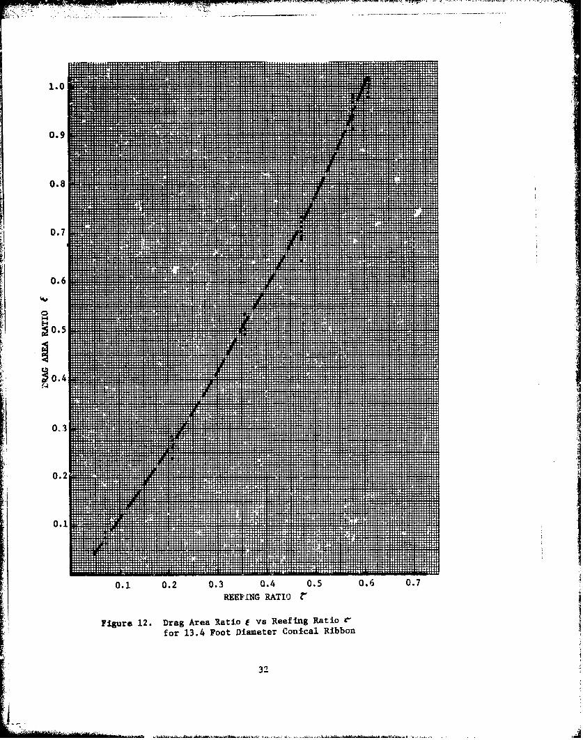
Tests were conducted by the USAF 6511th Test Group at theDepartment of Defense Joint Parachute Test Facility at El Centro,California, in 1960 with a 13.4 foot diameter drogue chute for theUS Army USD-5 (Fairchild M-252) Recon drone.
The parachute was a 25 degree conical ribbon parachute with20 suspension lines of 2250 pounds strength each, a suspensicn linelength of 13.4 ft (Ls/Do - 1.0) and a total canopy porosity AT = 25.4%
The parachute was towed behind a DC-130 aircraft on a 100 foottow line. Loads were measured with strain gages and the airspeedwith a calibrated airspeed indicator. The airspeed was changed insteps from 120 KIAS to 200 KIAS. The installed length of the2250 pound reefing line was measured under 20 pound tension.
Table 7 gives a summary of measured and calculated data.Figure 12 shows drag area ratioS vs reefing ratio% . Figure 10gives the average drag area ratio for each reefing ratio.
4
I
S~48
APPENDIX B
REEFING TESTS WITH A 3.0 FOOT DIAMETER FLAT
RIBBON PARACZnTTE FOR THE X-2 RESEARCH
AIRCRAFT IN THE WRIGHT FIELD 20 FOOT WIND TUNNEL
The USAF X-2 research aircraft was equipped with an ejectablenose section. In an emergency the pilot would eject the nose sectionand an automatically deployed drogue chute would stabilize anddecelerace the nose section. After descending to 5001 feet aboveground, the pilot would manually leave the nose section and descendwith a standard 28 foot man-carrying parachute.
Tests were conducted in 1950 in the Massie Memorial 20 footdiameter wind tunnel at Wright-Patterson AFB to determine the para-chute size required to stabilize the nose section and the reefingcharacteristics of this parachute. A 3/8 scale, dynamically similar,X-2 nose section was installed in the tunnel test section, free tooscillate around its pitch axis. In tests, the nose section wouldstabilize in the airstream at an angle of attack of approximately70 degreeo. A three foot diameter flat ribbon parachute reefed tovarious drag areas was then deployed and the minimum drag areadetermined necessaiy to stabilize the nose section close to zeroangle of attack. It became clear in these tests that the desirablepitch angle for parachute descent was not the zero angle of attack,
but the zero lift angle with the parachute force line passingthrough the C.G. of the nose section.
Prior to the nose section stabilization tests, the parachute wastested at various reefing stages at speeds varying from 100 mph to250 mph. The results of these reefing tests are tabulated in
Table 6, sheet 5. It will be of interest that in subsequent free-fall tests, the 3/8 scale nose section spur, at an angle of attackof approximately 70 degrees. Deploying the drogue chute, selectedin the wind tunnel tests, stabilized the nose section.
In actual flight tests, the X-2 research aircraft had an emergencyand the pilot ejected in the nose section. The subsequent investigationshowcd that the drogue chute opened at high supersonic speed, stabilized,and decelerated the nose section as designed.
Data on this system were never published due to the specializednature of the project.
49
Lim
REFERENCES
1. T. W. Knacke; "Reefing Methods, Parachutes," USAF Report TSEPE-627-25D, October 1947, ATI 26690.
2. M. H. L. Waters, D. B. Cobb, V. J. Bonnett, "Some Wind TunnelExperiments on the Reefing of Parachutes." Royal Aircraft EstablishmentTechnical Note No. Mech. Eng. 329, November 1960, AD 253328.
3. T. W. Knacke, "The Apollo Parachute Landing System," Proceedingsof the Thirl vunamic Deceleration System Conference, USAF FlightTest Center v ,Jrt FTC-TR-69-11, Vol. II, April 1969, AD 854169.
4. Ncwerop Corporation - Ventura Division (E. G. Ewing), "RingsailParachutc Design," USAF Report AFFDL-TR-72-3, January 1973, AD 745335.
5. S. S. Nash-Boulden, D. C. Coe, "Analysis of the Full-Scale andClustered One-Third Scale Apollo 88 Foot Ringsail Parachute Tests in theAmes 40 x 80 Foot Winc Tunnel - Second Series, "Northrop Corporation -
Ventura Division, Report NVR-3518, April 1964.
6. Anonymous, "United States Air Force Parachute Handbook," WADCTechnical Report 55-265, December 1956, AD 118036.
7. S. F. Groat, S. S. Nash-Boulden; "Analysis of Apollo Main ParachutesWind Tunnel Test Using Full, Half, and Third Scale Models, "NorthropCorporation-Ventura Division. Report NVD-2928, January 1964.
8. Anonym, Test Data provided by the AFFDL Recovery and Crew StationBranch.
9. T. W. Knacke, Unpublished Test Data, USAF 6511th Test Group, NAS ElCentro, CAlifornia.
10. J. F. Braun, W. B. Walcott, "Wind Tunnel Study of Parachute Clustering,"Technology Incorporated, April 1963, Report ASD-TDR-63-159, AD 402777.
11. Arnold B. Riffle, "Determination of the Aercdynamic Drag and StaticStability of Reefed Parachutes," Air Force Flight Dynamics Laboratory,AFFDL-TR-64-166, AD 459358.
12. T. W. Knacke, L. I. Dimmick; "Design Analysis of Final RecoveryParachutes, B-70 Encapsulated Seat and USD-5 Drone," Space RecoverySystems Irc., Report ASD-TDR-62-75, February 1962, AD 277424.
13. J. Reuther; Data provided by Pioneer Parachute Company on TriconicalParachutes, August 1975.
50
14. R. E. Linhart, "Final Report, AVCO MOD IR-A Recovery System,"Northrop Corporation-Ventura Division, Report NV-3618, February 1965.
15. 0. Sepp, Information Provided by the USAF/ASD B-1 System ProjectOffice, August 1975.
16. T. W. Knacke, Unpublished Data on Tests with a 13.4 Ft. Dia.Conical Ribbon Drogue Parachute for the USD-5 Recon. Drone, See AppendixA.
17. William Moore III, "64 Ft. FIST Ribbon Parachute (MX-1850)" USAF6511th Parachute Development Test Group, El Centro, Technical Note FTL-54-11, June 1954 and unpublished test data of the author.
18. K. D. Rosenlof, "Drag Coefficient of FIST Ribbon Paracl'xtes, Reefedand Fully Inflated," USAF 6511th Test Group, El Centro, Report •FTCTR-58-5, May 1958 and Notes of the Author, AD 131459.
19. T. W. Knacke, Unpublished Data on Wind Tunnel Tests with a 3.0 Ft.Dia. Ribbon Drogue Chute for the X-2 Aircraft Crew Module, USAF Wright-Patterson AFB, 1951, see Appendix B.
20. W. P. Peppj, "Full Scale Drop Tests and Scaled Model Wind TunnelTests of Ribbon Parachutes," Sandia Laboratories, Albuquerque, New Mexico.Report No. SC-DC-2360, University of Minnesota Lecture, July 1961.
21. W. P. Pepper, R. C. Maydew, "Aerodynamic Decelerators - An EngineeringReview," Sandia Laboratories, Albuquerque, New Mexico, Report SC-R-71-3156,January 1971.
22. F. E. Mickey, A. J. McEwan, E. G. Ewing, W. C. Huyle, Jr., B. Khajeh-Nouri, "Investigation of Prediction Methods for the Loads and Stressesof Apollo Type Spacecraft Parachutes," Northrop Corporation-VenturaDivision, Reports NVR-6431 (N74-19673) and NVR-6432 (N74-196 7 &), June 1970.
51" U. S GOVERM.ENT PRINTING OFFICEz 1976 -- 757-DOM/73


![[Book] Coldplay - Parachutes](https://img.pdfslide.us/doc/110x75/55cf925e550346f57b95ea12/book-coldplay-parachutes.jpg)